guide to life cycles and life cycle models - apm.org.uk · system-of-interest life cycle vs a...
TRANSCRIPT

The following document represents the thoughts and conclusions of the Systems Thinking SIG and not necessarily the views of the APM or INCOSE UK. It is intended to assist Project, Programme and Portfolio Management and Systems Engineering practitioners
wishing to explore concepts and ideas around Systems Thinking in P3M and to stimulate discussion on the subject. Feedback on the contents of this paper should be sent to the Systems Thinking SIG ([email protected]). It therefore does not
constitute any formal position (or liability arising) on the part of the International Council for Systems Engineering (INCOSE), INCOSE UK Ltd. or the Association for Project Management (APM), nor should any formal endorsement by these bodies be inferred.
Systems Engineering and Project Management (SEPM)
Joint Working Group
Guide to Life Cycles and Life Cycle Models
Issue 1.1
Mar 2017
Summary
The Joint Working Group (JWG) on Systems Engineering / Project Management Integration was formed by INCOSE UK and APM in 2013 as a result of a recognition by both organisations that closer integration of the two disciplines should increase the probability of project success. The aim of the JWG is to develop and promote good practice and guidance dovetailing SE and PM, and promote systems thinking across the wider decision making community in the UK.
As part of the work towards this aim, the JWG has been exploring aspects of SE and PM life cycles and processes. This document reviews various life cycle representations within the PM and SE disciplines, identifies where these representations overlap and are complementary, and explores area for potential confusion or mis-understanding between the disciplines.
The information within this document does not represent an exhaustive list, but provides a gateway to different life cycle representations and how they support decision making. This document is intended to be read in conjunction with its accompanying JWG documents, Guide to SE/PM Processes and Integration of Life Cycle Representations.
In order to aid comprehension, a categorisation of the range of life cycles is proposed, grouping them into Scenarios (strategic life cycles), Approaches (flows and interactions) and Models (methodology frameworks). These are not exhaustive or exclusive categories, but they help to describe the different nature of life cycle representations, particularly across the PM and SE disciplines and communities.
The role of the life cycle is explored, particularly as a governance and decision framework, and how this aligns the PM and SE disciplines and the management and development life cycles. Guidance is provided on life cycle selection, explaining the factors to be taken into account when considering which life cycle model to use.
Authors
Andrew Gray, Ken Richardson, Kate Rooke, Tony Thornburn
© 2016 A. Gray, K. Richardson, K. Rooke & T. Thornburn. Published and used by INCOSE UK Ltd., INCOSE and the Association for Project Management with permission.
Guide to Lifecycle Models: Issue 1.1 Page 2
Contents
1. Introduction 4 Purpose and Scope 4 Document Structure 5 Terminology 6 Key references 6 Acknowledgements 6
2. APM and INCOSE life cycle definitions 7 Definition of a life cycle 7 System engineering life cycles 8 Project, programme and portfolio life cycles 9 Other generic life cycle depictions 10
3. Categorising life cycle scenarios, approaches and models 11 Addressing a multitude of representations 11
4. Life cycle scenario category 13 Scenario types 13 Examples of new product/facility design development and introduction 13 Examples of transformational change 14 Examples of capability or service acquisition 16
5. Life cycle approach category 18 Life cycle Approaches 18 Using linear representations to illustrate the differences 18 Base approach 18 Experimental approach 19 Incremental approach 19 Evolutionary approach 19
6. Life cycle model category 21 Management models and development models 21 Examples of P3M life cycle models 21 Examples of sequential system development life cycle models 24 Examples of iterative and dynamic system development life cycle models 26
7. Category relationships and product life spans 29 Project life cycles and product life spans 29
8. Governance and feedback mechanisms 31 The life cycle as a governance and decision framework 31 Programme tranches and project stages 32 Use of stage gates 33
9. Comparisons of SE and P3M definitions 34 SE and P3M perspectives 34 System-of-interest life cycle vs a project/programme life cycle 34 Commonality of descriptions 35 Use of Vee Model to depict programme management strategy 35
10. Life cycle selection and tailoring 37 Align scenarios with strategic direction 37 Selecting the life cycle approach 37 The influence of risk 39 Follow, but monitor 40 Combine, but do not confuse 41
Guide to Lifecycle Models: Issue 1.1 Page 3
Figures Figure 1: Generic Life Cycle Representation (Adcock & Farncombe) 9 Figure 2: Linear Project Lifecycle (from APMBOK) 9 Figure 3: Linear programme lifecycle (from APMBOK) 10 Figure 4: Rational unified process life cycle 10 Figure 5: There are many different life cycle representations 11 Figure 6: A New Product Design Development and Introduction framework (©Cummins Turbo Technologies) 14 Figure 7: Panoptic Software Development Process (©Panoptic Development Inc) 14 Figure 8: RIBA Plan of Work 2013 (©Royal Institute of British Architects) 14 Figure 9: Transition from Current to Future State 15 Figure 10: NHS Change Model (©NHS) 16 Figure 11: UK MoD CADMID & CADMIT Acquisition Life Cycles 17 Figure 12: US DoD Acquisition Life Cycle 17 Figure 13: Example linear life cycle used to illustrate Base Approach 19 Figure 14: An example of an Experimental Approach 19 Figure 15: An example of an Incremental Approach 19 Figure 16: An example of an Evolutionary Approach 20 Figure 17: Simplified representation of PRINCE2® project management life cycle process model 22 Figure 18: ISO21500:2012 model of project phases 22 Figure 19: A representation of the Managing Successful Programmes® life cycle model 23 Figure 20: Portfolio definition and delivery cycles (after Management of Portfolios®) 23 Figure 21: Portfolio life cycle definition (after APMBOK) 24 Figure 22: Example Waterfall Models 25 Figure 23: Example extended Vee Model (after US DoT Federal Highway Administration) 26 Figure 24: Boehm’s Spiral Development Model 27 Figure 25: A representation of an agile development life cycle model (after Ambler & Lines) 28 Figure 26: Comparison of corporate business, facility/product and project life spans (Wideman 1987) 29 Figure 27: Hypothetical example illustrating life cycle categories and product life-span 30 Figure 28: Example use of Stage Gates within life cycle Phases at Airbus 32 Figure 29: Example use of Stage Gates within the life cycle (©Cummins Turbo Technologies) 33 Figure 30: SE and P3M – different perspectives on change 34 Figure 31: Programme Management as a Vee Model (encompassing SE elements) 35 Figure 32: Obeng’s descriptions of project types 38
Tables Table 1: Workstreams within the APM/INCOSE Joint Working Group 4 Table 2: Generic Systems Engineering Life Cycle Stages (from SEHBK) 8 Table 3: Life cycle approach selection table (adapted from Adcock & Farncombe 2009) 39 Table 4: An example of development model selection based on consideration of risk 40

Guide to Lifecycle Models: Issue 1.1 Page 4
1. Introduction
Purpose and Scope
In 2013 the UK chapter of the international council on systems engineering (INCOSE UK) and the association of project management (APM) founded a joint working group to realise this potential of collaborative working between project management (PM)1 and systems engineering (SE)2. This Joint Working Group was arranged into several Workstreams as shown in Table 1, of which Workstream 8 was set up to look at the processes and life cycles involved across the two disciplines.
Table 1: Workstreams within the APM/INCOSE Joint Working Group3
What are the benefits?
WS 1 Compelling value proposition
How to deliver the benefits?
WS 8 Processes and lifecycles
WS 4 Roles and responsibilities
WS 6 Competency framework
WS 7 Education and training
How to promote the benefits?
WS 2 Communication
WS 3 Guidance material
WS 5 Case studies
There are 3 main Objectives of Workstream 8 “Processes and Life Cycles”:4
1. To identify where SE and PM models, approaches and ways of working overlap and are
complementary, and identify the nature of the relationships between the two disciplines.
2. To develop (where appropriate) a set of unified processes and lifecycle models (or look to utilise
existing unified models and processes) .
1 The term ‘project management’ in this context encompasses all aspects of project, programme and portfolio management (P3M)
2 SE is an interdisciplinary approach and means to enable the realization of successful systems. Successful systems must satisfy the needs of its customers, users and other stakeholders (SEBoK v 1.7 BKCASE October 28,2016)
3 For further details on the APM/INCOSE JWG on SE/PM Integration, see JWG document “Aims and Objectives”, Version 1
4 See APM/INCOSE JWG on SE/PM Integration, “Workstream 8 Project Brief”, Version 1, September 2013

Guide to Lifecycle Models: Issue 1.1 Page 5
3. To communicate, review and exploit these processes and lifecycle models amongst the PM and SE
communities.
This document addresses Objectives 1 and 3 from a life cycle perspective. When looking at life cycles it is worth noting that we are considering any change situation, including the introduction or modification of products or capabilities. The purpose of this document is to form a framework around which key messages and information can be captured related to the subject of life cycles within the PM and SE environments. This therefore also means that information can be provided in support of the other Workstreams.
It is not intended as an exhaustive guide to the range of life cycle representations that are used.
A life cycle should be chosen based on what works for the undertaking in question, and therefore selecting and tailoring a life cycle is a key function. This guide aims to equip the reader with a better understanding of the options available in order to support this decision and address the complexity often associated with projects that require both a strong SE and PM function.
This guide is not intended to compare and review individual processes within the life cycles. This will be undertaken in an accompanying publication “Guide to SE and P3M Processes”. Developments in integrating life cycle representations identified in this document can be found in the third document in this series - “Integrated Life Cycle Representations” (and which therefore specifically addresses Workstream Objective 2).
Document Structure
This document explores the relationships between lifecycle representations in P3M and Systems Engineering through 10 chapters. In addition to this introduction, these chapters cover:
What is a life cycle? APM and INCOSE life cycle definitions. A comparison of various definitions of a life cycle and whether any conflicts arise from differences in definitions.
What sort of life cycles are there?
Categorising life cycle scenarios, approaches and models. Describes a means of categorisation of the wide range of different life cycle representations, and introduces the Scenario, Approach and Model categories.
What is a life cycle scenario?
Life cycle scenario category. A review of certain P3M process frameworks, covering those within the APM Body of Knowledge, the PMI Body of Knowledge, ISO standards and the Global Best Practice Suite from Axelos.
What is a life cycle approach?
Life cycle approach category. Identification of the overlap of processes included within SE and P3M frameworks, using the ISO standards for a back-to-back comparison.
What is a life cycle model?
Life cycle model category. Identification of key areas where SE and P3M processes can combine or interact to provide an enhanced performance or output.
How do scenarios, approaches and models interact?
Category relationships and product life spans. A review of how the scenarios, approaches and models combine, and how where overlaps and frictions can arise between SE and P3M processes, including the relationship between the product life span and the project life cycle.
How do life cycles help provide control?
Governance and feedback mechanisms. Explores how PM and SE life cycle representations underpin aspects of governance and provide a decision framework, particularly through the use of stage gates.
What differences are there between SE and PM perspectives?
Comparisons of SE and P3M definitions. The consideration of the different perspectives between the SE and PM disciplines, and how a system representation of the programme life cycle could be used.
How do we select the most appropriate life cycle representation?
Life cycle selection and tailoring. Considerations to be taken into account when selecting life cycle representations to be used as a foundation for defining and communicating the work to be undertaken.

Guide to Lifecycle Models: Issue 1.1 Page 6
Terminology
The term “life cycle” can also be denoted by “lifecycle” or “life-cycle”. In this document the term “life cycle” is used throughout except where providing a direct reference to a source that uses a different form.
The term P3 is used to denote Project, Programmes and Portfolios (as defined within the APM Body of Knowledge), and P3M denotes Project, Programme and Portfolio Management. Where the discussion only refers specifically to Projects and Programmes, the term PPM will be used. SE is used to denote Systems Engineering approaches, models, processes and ways of thinking.
The term ‘stage’ is used in the INCOSE SE Handbook to denote an element of a life cycle. The term ‘phase’ is typically used in P3M literature, for example the APM Body of Knowledge. Whilst these are generally interchangeable, the term ‘stage’ has specific connotations (for example in PRINCE2®) and so in this document the term ‘phase’ will be used to denote an element of a life cycle (except where a specific reference uses an alternative term).
Key references
Unless otherwise referenced, information is taken from the INCOSE System Engineering Handbook (SEHBK) v3.2.2 (2011) or the APM Body of Knowledge (APMBOK) 6th Edition (2012). Key references will also include information from the ISO Standard on Systems and Software Engineering – System life cycle processes (ISO15288:2015) and the ISO Standard on Project Management (ISO21500:2012)5. Use has also been made of the information contained within the Guide to the System Engineering Body of Knowledge6.
Acknowledgements
The authors would like to acknowledge in particular the contribution of Dr. James Goodwin to the sections on life cycle categorisation, as well as the inputs, advice and support of the other members of the Joint Working Group.
5 Note that ISO21502 (Project and Programme Portfolio Management) and ISO21504 (Programme Management) are currently in draft form.
6 Guide to the System Engineering Body of Knowledge, Fourth Edition INCOSE-TP-2003-002-04 2015 , available at http://www.sebokwiki.org/
Guide to Lifecycle Models: Issue 1.1 Page 7
2. APM and INCOSE life cycle definitions
In this chapter we review the various definitions of a life cycle and whether these definitions give rise to tensions between the Systems Engineering and P3M disciplines.
Definition of a life cycle
Within various key reference sources, there are a number of definitions of a life cycle.
Collins Dictionary7 defines a life cycle as
The life cycle of something such as an idea, product, or organization is the series of developments that take place in it from its beginning until the end of its usefulness.
ISO15288:2015 defines a life cycle as
evolution of a system, product, service, project or other human-made entity from conception through retirement.
ISO 21500:2012 defines a project life cycle as
A collection of project phases spanning the period from project start to project end, during which activities are performed using resources to provide deliverables. Phases are divided by decision points which vary according to the organisational environment.
The APMBOK8 defines a life cycle as
A life cycle defines the inter-related phases of a project, programme or portfolio and provides a structure for governing the progression of the work.
The SEHBK9 does not define what a life cycle is per se (as it draws upon ISO15288), but does state that its purpose is
To establish a framework for meeting the stakeholder’s needs in an orderly and efficient manner for the whole life cycle.
From these different definitions it can already be seen where confusion between SE and P3M might lie in discussing appropriate life cycles. The key difference is that a project life cycle ends at a defined point when
7 Collins Learner Dictionary, online version, www.collinsdictionary.com/dictionary/english-cobuild-learners/life-cycle [accessed 9th September 2014]
8 See APMBOK Section 1.1.6, “Life cycle”
9 See SEHBK Section 3.1, “Generic Life-Cycle Stages”
Guide to Lifecycle Models: Issue 1.1 Page 8
the project ends, whereas a system life cycle ends on disposal/retirement of the system itself. Although the two could correspond (for example in an evolutionary life cycle approach10), typically this is not the case.
System engineering life cycles
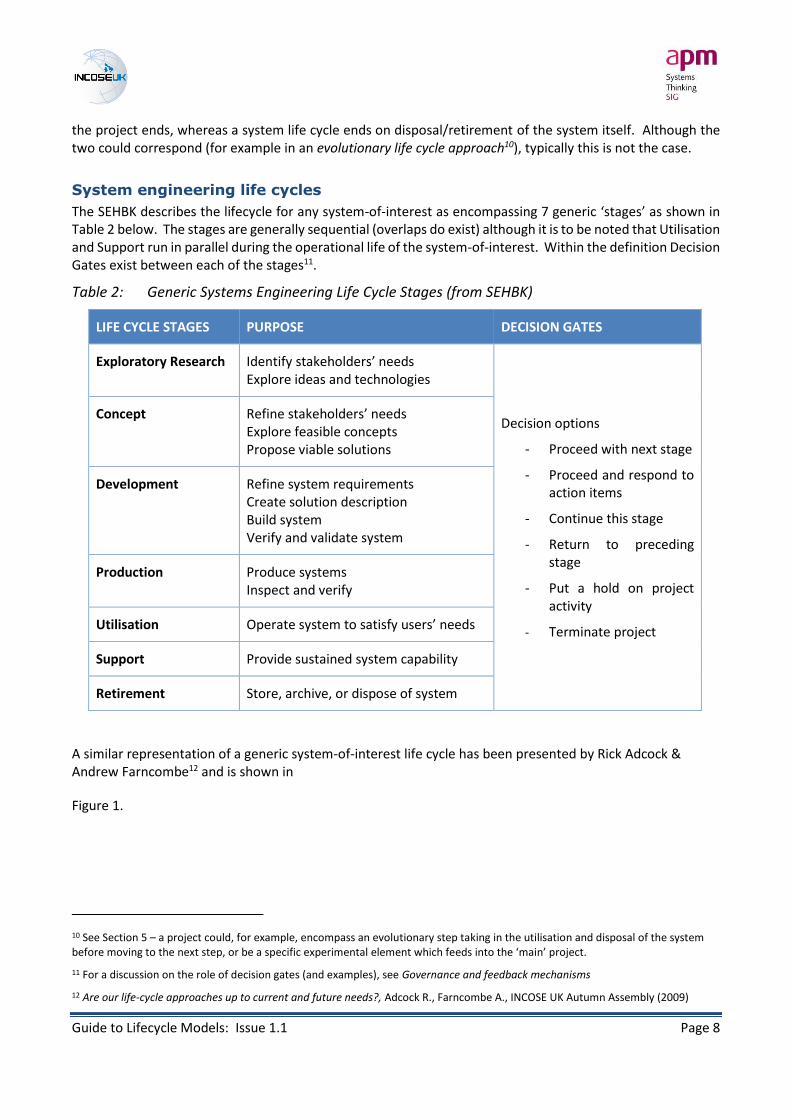
The SEHBK describes the lifecycle for any system-of-interest as encompassing 7 generic ‘stages’ as shown in Table 2 below. The stages are generally sequential (overlaps do exist) although it is to be noted that Utilisation and Support run in parallel during the operational life of the system-of-interest. Within the definition Decision Gates exist between each of the stages11.
Table 2: Generic Systems Engineering Life Cycle Stages (from SEHBK)
LIFE CYCLE STAGES PURPOSE DECISION GATES
Exploratory Research Identify stakeholders’ needs Explore ideas and technologies
Decision options
- Proceed with next stage
- Proceed and respond to action items
- Continue this stage
- Return to preceding stage
- Put a hold on project activity
- Terminate project
Concept Refine stakeholders’ needs Explore feasible concepts Propose viable solutions
Development Refine system requirements Create solution description Build system Verify and validate system
Production Produce systems Inspect and verify
Utilisation Operate system to satisfy users’ needs
Support Provide sustained system capability
Retirement Store, archive, or dispose of system
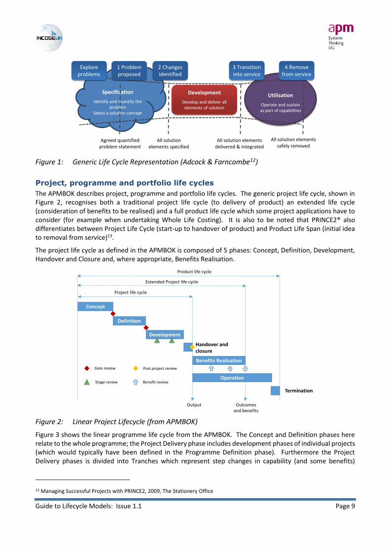
A similar representation of a generic system-of-interest life cycle has been presented by Rick Adcock & Andrew Farncombe12 and is shown in
Figure 1.
10 See Section 5 – a project could, for example, encompass an evolutionary step taking in the utilisation and disposal of the system before moving to the next step, or be a specific experimental element which feeds into the ‘main’ project.
11 For a discussion on the role of decision gates (and examples), see Governance and feedback mechanisms
12 Are our life-cycle approaches up to current and future needs?, Adcock R., Farncombe A., INCOSE UK Autumn Assembly (2009)
Guide to Lifecycle Models: Issue 1.1 Page 9
Figure 1: Generic Life Cycle Representation (Adcock & Farncombe12)
Project, programme and portfolio life cycles
The APMBOK describes project, programme and portfolio life cycles. The generic project life cycle, shown in Figure 2, recognises both a traditional project life cycle (to delivery of product) an extended life cycle (consideration of benefits to be realised) and a full product life cycle which some project applications have to consider (for example when undertaking Whole Life Costing). It is also to be noted that PRINCE2® also differentiates between Project Life Cycle (start-up to handover of product) and Product Life Span (initial idea to removal from service)13.
The project life cycle as defined in the APMBOK is composed of 5 phases: Concept, Definition, Development, Handover and Closure and, where appropriate, Benefits Realisation.
Figure 2: Linear Project Lifecycle (from APMBOK)
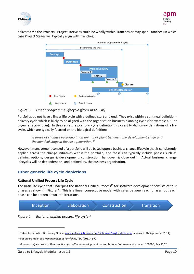
Figure 3 shows the linear programme life cycle from the APMBOK. The Concept and Definition phases here relate to the whole programme; the Project Delivery phase includes development phases of individual projects (which would typically have been defined in the Programme Definition phase). Furthermore the Project Delivery phases is divided into Tranches which represent step changes in capability (and some benefits)
13 Managing Successful Projects with PRINCE2, 2009, The Stationery Office
Specification
Identify and quantify the problem
Select a solution concept
Development
Develop and deliver all elements of solution
Utilisation
Operate and sustain as part of capabilities
3 Transition into service
Agreed quantified problem statement
All solution elements specified
All solution elements delivered & integrated
All solution elements safely removed
Explore problems
1 Problem proposed
2 Changes identified
4 Remove from service
Concept
Definition
Development
Handover andclosure
Benefits Realisation
Operation
Termination
Output Outcomesand benefits
Project life cycle
Extended Project life cycle
Product life cycle
Gate review
Stage review
Post project review
Benefit review
Guide to Lifecycle Models: Issue 1.1 Page 10
delivered via the Projects. Project lifecycles could be wholly within Tranches or may span Tranches (in which case Project Stages will typically align with Tranches).
Figure 3: Linear programme lifecycle (from APMBOK)
Portfolios do not have a linear life cycle with a defined start and end. They exist within a continual definition-delivery cycle which is likely to be aligned with the organisation business planning cycle (for example a 3- or 5-year strategic plan). In this sense the portfolio cycle definition is closest to dictionary definitions of a life cycle, which are typically focused on the biological definition:
A series of changes occurring in an animal or plant between one development stage and the identical stage in the next generation. 14
However, management control of a portfolio will be based upon a business change lifecycle that is consistently applied across the change initiatives within the portfolio, and these can typically include phases such as defining options, design & development, construction, handover & close out15. Actual business change lifecycles will be dependent on, and defined by, the business organisation.
Other generic life cycle depictions
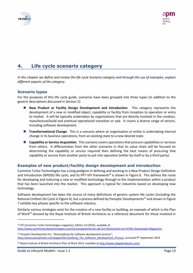
Rational Unified Process Life Cycle
The basic life cycle that underpins the Rational Unified Process16 for software development consists of four phases as shown in Figure 4. This is a linear consecutive model with gates between each phases, but each phase can be broken down into iterations.
Figure 4: Rational unified process life cycle16
14 Taken from Collins Dictionary Online, www.collinsdictionary.com/dictionary/english/life-cycle [accessed 9th September 2014]
15 For an example, see Management of Portfolios, TSO (2011), p72
16 Rational unified process: Best practices for software development teams, Rational Software white paper, TP026B, Rev 11/01
Concept
Definition
Project Delivery
Closure
Benefits Realisation
Programme life cycle
Extended programme life cycle
Gate review
Stage review
Post project review
Benefit review
Tranche 1
Tranche 2
Tranche 3
Inception Elaboration Construction Transition
Guide to Lifecycle Models: Issue 1.1 Page 11
3. Categorising life cycle scenarios, approaches and
models
In this chapter we address the wide range of different life cycle representations and why it is necessary to devise a categorisation framework to help explore the different aspects of life cycle representations.
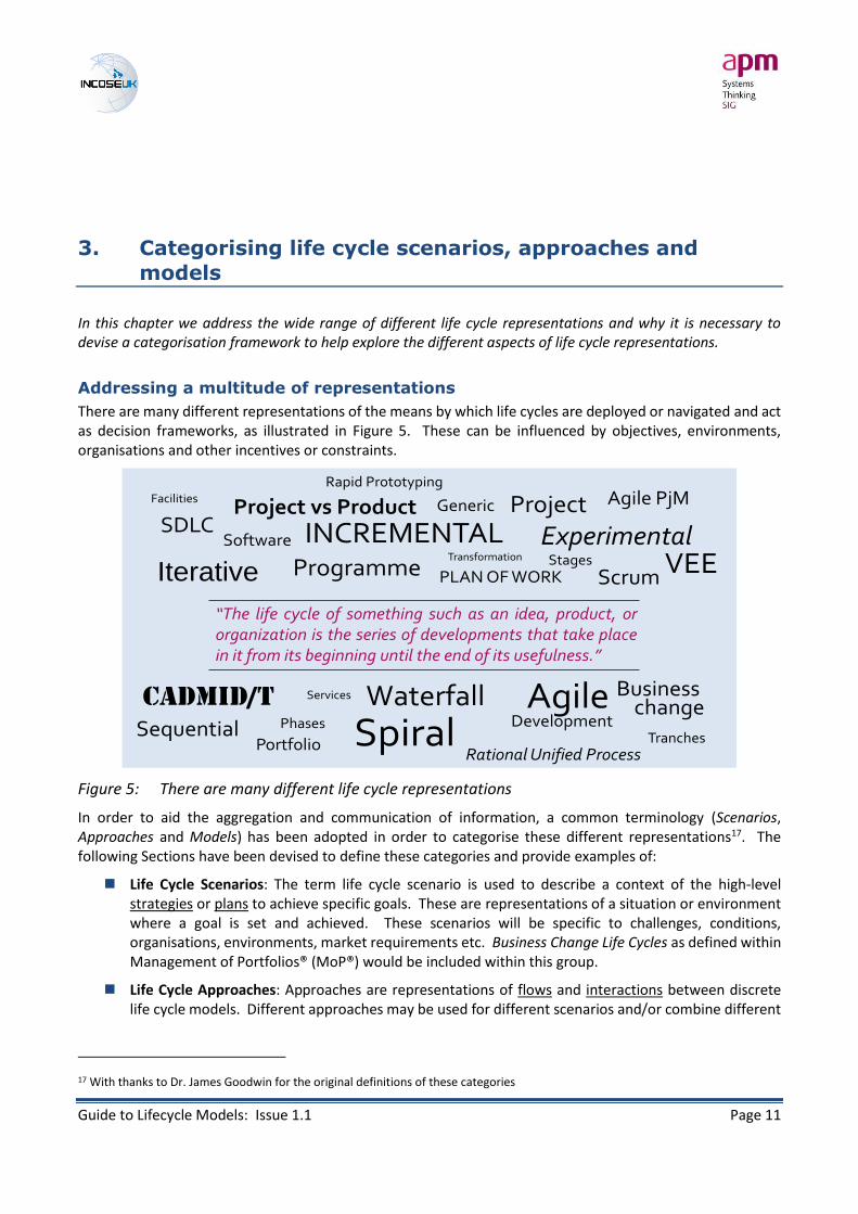
Addressing a multitude of representations
There are many different representations of the means by which life cycles are deployed or navigated and act as decision frameworks, as illustrated in Figure 5. These can be influenced by objectives, environments, organisations and other incentives or constraints.
Figure 5: There are many different life cycle representations
In order to aid the aggregation and communication of information, a common terminology (Scenarios, Approaches and Models) has been adopted in order to categorise these different representations17. The following Sections have been devised to define these categories and provide examples of:
Life Cycle Scenarios: The term life cycle scenario is used to describe a context of the high-level strategies or plans to achieve specific goals. These are representations of a situation or environment where a goal is set and achieved. These scenarios will be specific to challenges, conditions, organisations, environments, market requirements etc. Business Change Life Cycles as defined within Management of Portfolios® (MoP®) would be included within this group.
Life Cycle Approaches: Approaches are representations of flows and interactions between discrete life cycle models. Different approaches may be used for different scenarios and/or combine different
17 With thanks to Dr. James Goodwin for the original definitions of these categories
AgileDevelopment
Waterfall
Iterative
Spiral
INCREMENTAL
Rational Unified Process
CADMID/T
VEEScrum
ExperimentalProject
Programme
Business change
Sequential
GenericSDLC
Agile PjM
PLAN OF WORK
Transformation
Portfolio
Project vs ProductRapid Prototyping
TranchesPhases
Stages
Software
Facilities
Services
“The life cycle of something such as an idea, product, ororganization is the series of developments that take placein it from its beginning until the end of its usefulness.”

Guide to Lifecycle Models: Issue 1.1 Page 12
models. Approaches can be related to overall change programme strategies (when considered as part of a P3M environment).
Life Cycle Models: a depiction of a methodology or framework of processes and activities within the life cycle phases that depict the elements that are undertaken and how they relate together. This definition is in line with the life cycle model definition within ISO 15288:2015 - aframework of processes and activities concerned with the life cycle that may be organized into stages, which also acts as a common reference for communication and understanding. Models would typically be employed at the project level (but this is not a rigid principle).
It must be emphasised that these categories and their descriptions are principally an aid to understanding the purpose of any life cycle representation, and how these representations are necessary in order to determine, and support, the execution of activities. It is not an exhaustive categorisation of all representations, nor do all representations fall neatly into these categories.
Whilst examples of each representation category are described separately in the following Sections, this does not mean that each is mutually exclusive. In reality the means by which the life cycle is navigated can be a combination of different representations. The definitions above also include a rough mapping against a portfolio, programme and project framework – these should not be taken to infer a precise unique mapping, but they are included to help illustrate the relationships between the representation categories.
An example of the relationships between these categories is given in the section following those describing each of the categories – see Category relationships and product life spans (p29).
Guide to Lifecycle Models: Issue 1.1 Page 13
4. Life cycle scenario category
In this chapter we define and review the life cycle Scenario category and through the use of examples, explore different aspects of the category.
Scenario types
For the purposes of this life cycle guide, scenarios have been grouped into three types (in addition to the generic descriptions discussed in Section 2):
New Product or Facility Design Development and Introduction. This category represents the development of a new or modified object, capability or facility from inception to operation or entry to market. It will be typically undertaken by organisations that are directly involved in the creation, manufacture/build and eventual operational transition or sale. It covers a diverse range of sectors, including software development.
Transformational Change. This is a scenario where an organisation or entity is undertaking internal change in its business operations, from an existing state to a new desired state.
Capability or Service Acquisition. This scenario covers operations that procure capabilities or services from others. It differentiates from the other scenarios in that its value chain will be focused on determining the capability or service required then defining the best means of procuring that capability or service from another party to put into operation (either by itself or by a third party).
Examples of new product/facility design development and introduction
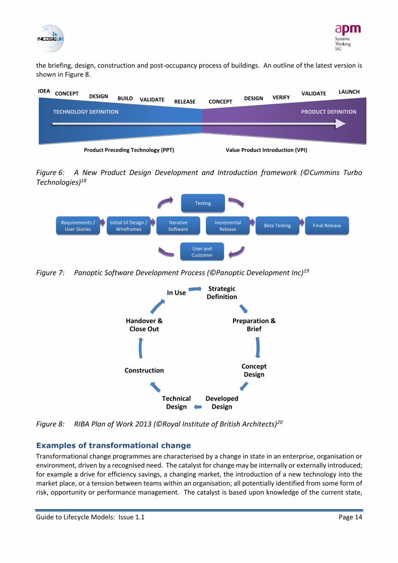
Cummins Turbo Technologies has a long pedigree in defining and working to a New Product Design Definition and Introduction (NPDDI) life cycle, and its PPT-VPI framework18 is shown in Figure 6. This defines the route for developing and maturing a new or modified technology through to the implementation within a product that has been launched into the market. This approach is typical for industries based on developing new technology.
Software development has been the source of many definitions of generic system life cycles (including the Rational Unified Life Cycle in Figure 4), but a process defined by Panoptic Developments19 and shown in Figure 7 exhibits key phases specific to the software industry.
Similarly various strategies exist for the creation of a new facility or building, an example of which is the Plan of Work20 devised by the Royal Institute of British Architects as a reference document for those involved in
18 HTi (Cummins Turbo Technologies magazine), Edition 14 (2010), available at http://www.cumminsturbotechnologies.com/ctt/navigationAction.do?url=SiteContent+en+HTML+Downloads+Magazines
19 Panoptic Development Inc, “Demystifying the software development process”, http://www.panopticdev.com/pages/Demystifying_The_Software_Development_Process, accessed 9th September 2014
20 Royal Institute of British Architects Plan of Work 2013, available at http://www.ribaplanofwork.com/
Guide to Lifecycle Models: Issue 1.1 Page 14
the briefing, design, construction and post-occupancy process of buildings. An outline of the latest version is shown in Figure 8.
Figure 6: A New Product Design Development and Introduction framework (©Cummins Turbo Technologies)18
Figure 7: Panoptic Software Development Process (©Panoptic Development Inc)19
Figure 8: RIBA Plan of Work 2013 (©Royal Institute of British Architects)20
Examples of transformational change
Transformational change programmes are characterised by a change in state in an enterprise, organisation or environment, driven by a recognised need. The catalyst for change may be internally or externally introduced; for example a drive for efficiency savings, a changing market, the introduction of a new technology into the market place, or a tension between teams within an organisation; all potentially identified from some form of risk, opportunity or performance management. The catalyst is based upon knowledge of the current state,
Strategic Definition
Preparation & Brief
Concept Design
Developed Design
Technical Design
Construction
Handover & Close Out
In Use
IDEA CONCEPT DESIGN BUILD VALIDATE RELEASE
TECHNOLOGY DEFINITION PRODUCT DEFINITION
CONCEPT DESIGN VERIFY
VALIDATE LAUNCH
Product Preceding Technology (PPT) Value Product Introduction (VPI)
Requirements / User Stories
Initial UI Design / Wireframes
Iterative Software
Development
Incremental Release
Beta Testing Final Release
Testing
User and Customer Feedback
Guide to Lifecycle Models: Issue 1.1 Page 15
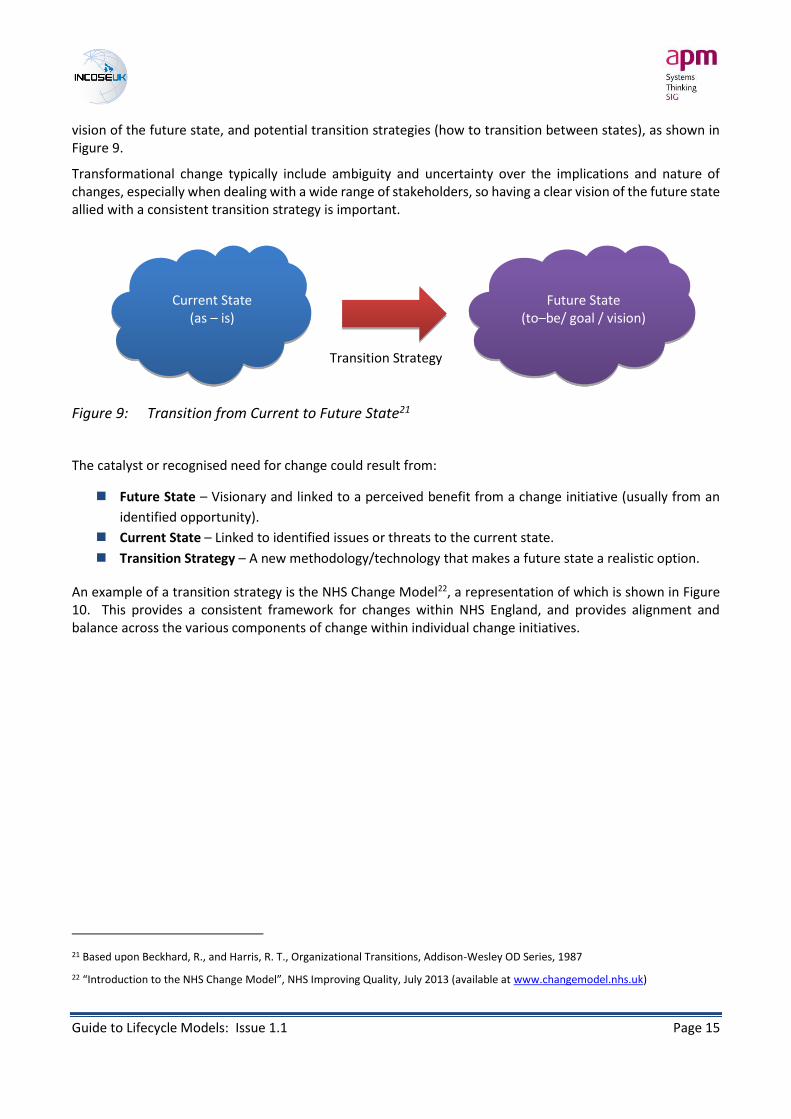
vision of the future state, and potential transition strategies (how to transition between states), as shown in Figure 9.
Transformational change typically include ambiguity and uncertainty over the implications and nature of changes, especially when dealing with a wide range of stakeholders, so having a clear vision of the future state allied with a consistent transition strategy is important.
Figure 9: Transition from Current to Future State21
The catalyst or recognised need for change could result from:
Future State – Visionary and linked to a perceived benefit from a change initiative (usually from an
identified opportunity).
Current State – Linked to identified issues or threats to the current state.
Transition Strategy – A new methodology/technology that makes a future state a realistic option.
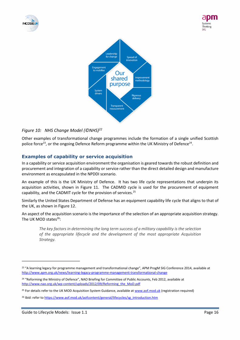
An example of a transition strategy is the NHS Change Model22, a representation of which is shown in Figure 10. This provides a consistent framework for changes within NHS England, and provides alignment and balance across the various components of change within individual change initiatives.
21 Based upon Beckhard, R., and Harris, R. T., Organizational Transitions, Addison-Wesley OD Series, 1987
22 “Introduction to the NHS Change Model”, NHS Improving Quality, July 2013 (available at www.changemodel.nhs.uk)
Transition Strategy
Current State (as – is)
Future State (to–be/ goal / vision)
Guide to Lifecycle Models: Issue 1.1 Page 16
Figure 10: NHS Change Model (©NHS)22
Other examples of transformational change programmes include the formation of a single unified Scottish police force23, or the ongoing Defence Reform programme within the UK Ministry of Defence24.
Examples of capability or service acquisition
In a capability or service acquisition environment the organisation is geared towards the robust definition and procurement and integration of a capability or service rather than the direct detailed design and manufacture environment as encapsulated in the NPDDI scenario.
An example of this is the UK Ministry of Defence. It has two life cycle representations that underpin its acquisition activities, shown in Figure 11. The CADMID cycle is used for the procurement of equipment capability, and the CADMIT cycle for the provision of services.25
Similarly the United States Department of Defense has an equipment capability life cycle that aligns to that of the UK, as shown in Figure 12.
An aspect of the acquisition scenario is the importance of the selection of an appropriate acquisition strategy. The UK MOD states26:
The key factors in determining the long term success of a military capability is the selection of the appropriate lifecycle and the development of the most appropriate Acquisition Strategy.
23 “A learning legacy for programme management and transformational change”, APM ProgM SIG Conference 2014, available at http://www.apm.org.uk/news/learning-legacy-programme-management-transformational-change
24 “Reforming the Ministry of Defence”, NAO Briefing for Committee of Public Accounts, Feb 2012, available at http://www.nao.org.uk/wp-content/uploads/2012/09/Reforming_the_MoD.pdf
25 For details refer to the UK MOD Acquisition System Guidance, available at www.aof.mod.uk (registration required)
26 Ibid: refer to https://www.aof.mod.uk/aofcontent/general/lifecycles/sg_introduction.htm

Guide to Lifecycle Models: Issue 1.1 Page 17
Acquisition strategies can be many and varied. Patterson27 describes four strategies: Commercial off the Shelf (COTS); Performance Based Contracting (PBC); Cost-Plus Contracting, and In-House Development.
Figure 11: UK MoD CADMID & CADMIT Acquisition Life Cycles25
Figure 12: US DoD Acquisition Life Cycle
27 Patterson F.G., Jr., (2004/Rev.2006), LIFE CYCLES FOR SYSTEM ACQUISITION, in Systems Engineering and Management for Sustainable Development, [Ed. Andrew P. Sage], in Encyclopedia of Life Support Systems (EOLSS), Developed under the Auspices of the UNESCO, Eolss Publishers, Oxford ,UK, [http://www.eolss.net]
Concept Assessment Demonstration Manufacture In-Service Disposal
Concept Assessment Demonstration Migrate In-Service Terminate
Mission analysis
Concept exploration
Full ScaleDevelopment
Production Use & Support Disposal

Guide to Lifecycle Models: Issue 1.1 Page 18
5. Life cycle approach category
In this chapter we define and review the life cycle Approach category and through the use of examples, explore different aspects of the category. The definitions of the Approach category have been taken (and adapted) from Adcock & Farncombe (2009)12.
Life cycle Approaches
Approaches are representations of flows and interactions between discrete life cycle models, and can typically describe the core skeleton of the overall plan for introducing a specific change (as opposed to the generic representation of a Scenario). Different approaches may be used for different scenarios and/or combine different life cycle models. Approaches can be related to individual change programme strategies (when considered as part of a P3M environment).
The definition of life cycle approaches follows the work of Adcock & Farncombe (2009), who described different approaches within 4 sub-categories:
• Base
• Experimental
• Incremental
• Evolutionary
Using linear representations to illustrate the differences
As it is noted in the SEHBK, graphical representations of life cycles tend to be of a linear form, but these may hide any recursive nature of the underlying processes. The life cycle illustrations in the following descriptions of the Approach sub-categories also follow this linear tendency. They should be used to compare differences in the underlying principles of each Approach and the advantages and disadvantages of each, not to specify or dictate the exact course of action to follow in every situation.
Base approach
A Base approach is a single pass through the life cycle phases to develop a system-of-interest. It can be tailored as required and works well for well-defined problems and stable technology, but it is difficult to deal with complex situations or problems. Figure 13 shows a set of simple life cycle phases (in a sequential model) and these will be used to only illustrate the Experimental, Incremental and Evolutionary approaches. The following approaches would be used with whatever phases/models are appropriate. For example, the SEHBK28 includes an illustration of a combined incremental and evolutionary development approach (using a Vee Model).
28 SEHBK Section 3.4.2 Figure 3-8 p34
Guide to Lifecycle Models: Issue 1.1 Page 19
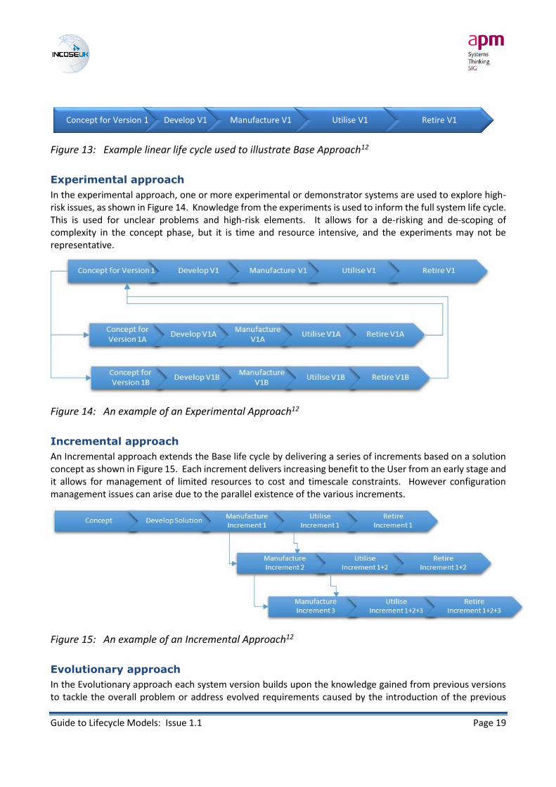
Figure 13: Example linear life cycle used to illustrate Base Approach12
Experimental approach
In the experimental approach, one or more experimental or demonstrator systems are used to explore high-risk issues, as shown in Figure 14. Knowledge from the experiments is used to inform the full system life cycle. This is used for unclear problems and high-risk elements. It allows for a de-risking and de-scoping of complexity in the concept phase, but it is time and resource intensive, and the experiments may not be representative.
Figure 14: An example of an Experimental Approach12
Incremental approach
An Incremental approach extends the Base life cycle by delivering a series of increments based on a solution concept as shown in Figure 15. Each increment delivers increasing benefit to the User from an early stage and it allows for management of limited resources to cost and timescale constraints. However configuration management issues can arise due to the parallel existence of the various increments.
Figure 15: An example of an Incremental Approach12
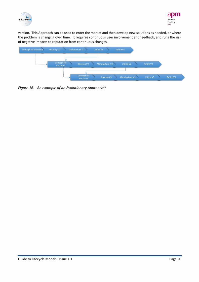
Evolutionary approach
In the Evolutionary approach each system version builds upon the knowledge gained from previous versions to tackle the overall problem or address evolved requirements caused by the introduction of the previous
Concept for Version 1 Develop V1 Manufacture V1 Utilise V1 Retire V1
Guide to Lifecycle Models: Issue 1.1 Page 20
version. This Approach can be used to enter the market and then develop new solutions as needed, or where the problem is changing over time. It requires continuous user involvement and feedback, and runs the risk of negative impacts to reputation from continuous changes.
Figure 16: An example of an Evolutionary Approach12

Guide to Lifecycle Models: Issue 1.1 Page 21
6. Life cycle model category
In this chapter we define and review the life cycle Model category and through the use of examples, explore different aspects of the category. The Model category includes many different representations, but these fall into two sub-categories – management models (which are typically the P3M models) and development models (typically the various different system development models).
Management models and development models
Both the SE and P3M disciplines have a number of life cycle models that act as frameworks for the various processes that constitute the work to be undertaken to deliver specific outputs. P3M models are focused on the governance, controls and assurance of the project, programme or portfolio life cycle (and their relationship to each other), whilst SE models typically address different solution development philosophies (whilst providing the means for management of the solution development). The basic underlying phases of initiate, define, deliver and close are common to all, and therefore both sets need to be examined to ensure that there are no key differences that would prevent appropriate management and development life cycle models working in harmony. Both management and development life cycle models act as robust decision-making frameworks.
Examples of P3M life cycle models
Project management life cycle model
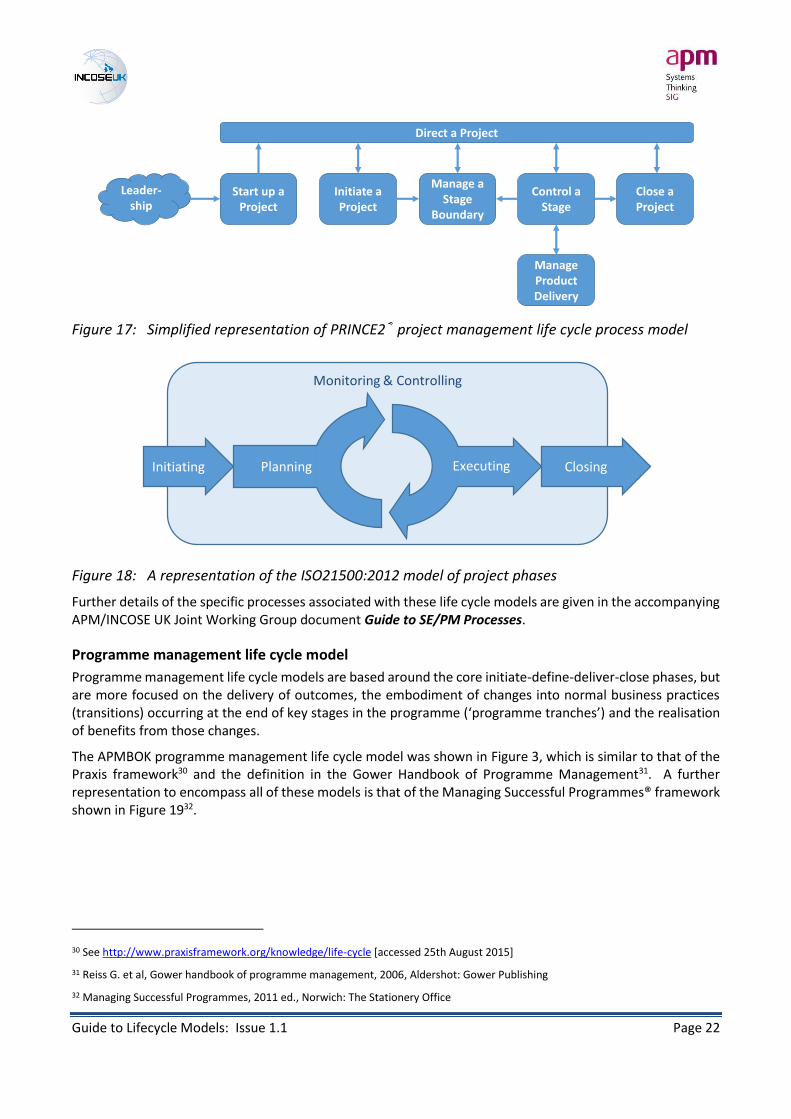
Key examples of project management life cycle models/frameworks include those of PRINCE2® shown in Figure 17, APMBOK shown previously in Figure 2, and that of the PMI Guide to the PM Body of Knowledge (PMBOK) shown in Figure 18. The life cycle definition in ISO21500:2012 is based upon that of the PMBOK.
Project management models can be shown as a linear progression, but they can typically involve iterative loops around the planning and delivery/execution phases – such as the examples in Figure 17 and Figure 18, as well as combinations following incremental or evolutionary approaches, such as the Praxis framework iterative representation29 or the combinations presented in the PMBOK.
29 See http://www.praxisframework.org/knowledge/life-cycle [accessed 25th August 2015]
Guide to Lifecycle Models: Issue 1.1 Page 22
Figure 17: Simplified representation of PRINCE2® project management life cycle process model
Figure 18: A representation of the ISO21500:2012 model of project phases
Further details of the specific processes associated with these life cycle models are given in the accompanying APM/INCOSE UK Joint Working Group document Guide to SE/PM Processes.
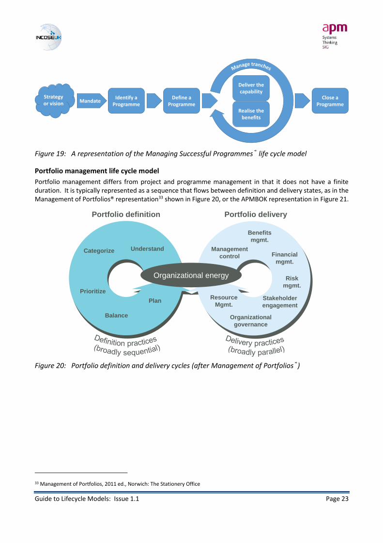
Programme management life cycle model
Programme management life cycle models are based around the core initiate-define-deliver-close phases, but are more focused on the delivery of outcomes, the embodiment of changes into normal business practices (transitions) occurring at the end of key stages in the programme (‘programme tranches’) and the realisation of benefits from those changes.
The APMBOK programme management life cycle model was shown in Figure 3, which is similar to that of the Praxis framework30 and the definition in the Gower Handbook of Programme Management31. A further representation to encompass all of these models is that of the Managing Successful Programmes® framework shown in Figure 1932.
30 See http://www.praxisframework.org/knowledge/life-cycle [accessed 25th August 2015]
31 Reiss G. et al, Gower handbook of programme management, 2006, Aldershot: Gower Publishing
32 Managing Successful Programmes, 2011 ed., Norwich: The Stationery Office
Direct a Project
Start up a Project
Initiate a Project
Manage a Stage
Boundary
Control a Stage
Manage Product Delivery
Close a Project
Leader-ship
Monitoring & Controlling
Initiating ClosingPlanning Executing
Guide to Lifecycle Models: Issue 1.1 Page 23
Figure 19: A representation of the Managing Successful Programmes® life cycle model
Portfolio management life cycle model
Portfolio management differs from project and programme management in that it does not have a finite duration. It is typically represented as a sequence that flows between definition and delivery states, as in the Management of Portfolios® representation33 shown in Figure 20, or the APMBOK representation in Figure 21.
Figure 20: Portfolio definition and delivery cycles (after Management of Portfolios®)
33 Management of Portfolios, 2011 ed., Norwich: The Stationery Office
Strategy or vision Mandate
Identify a Programme
Define a Programme
Deliver the capability
Realise the benefits
Close a Programme
Organizational energy
Portfolio definition Portfolio delivery
UnderstandCategorize
Prioritize
Balance
Plan
Management
control
Benefits
mgmt.
Financial
mgmt.
Risk
mgmt.
Stakeholder
engagement
Organizational
governance
Resource
Mgmt.

Guide to Lifecycle Models: Issue 1.1 Page 24
Figure 21: Portfolio life cycle definition (after APMBOK)
Examples of sequential system development life cycle models
Waterfall
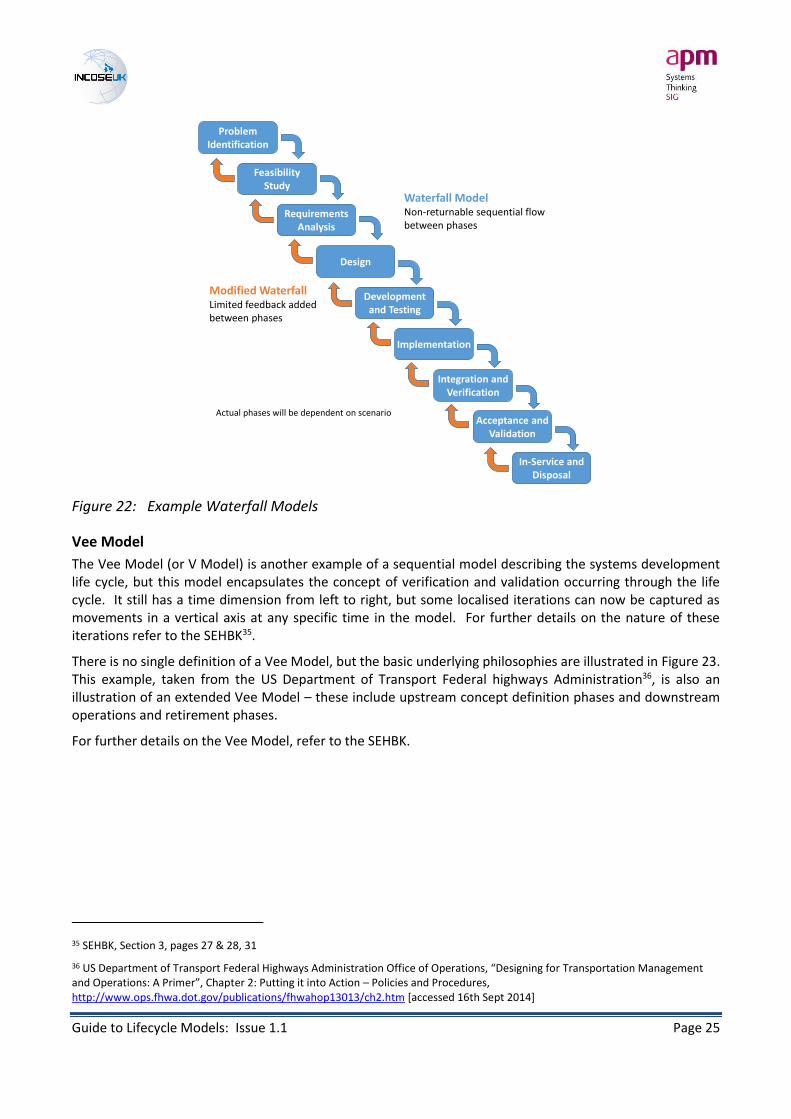
The ‘classic’ waterfall development model is defined as a linear sequential flow where activity moves from one phase to the next only when the preceding phase is complete and frozen. Different phases may be represented in the model, for example the variant shown in Figure 22, and these will be determined by the scenario in which the model is used. The term ‘waterfall’ implies a non-returnable flow from conception to completion.
A ‘modified’ variant of the waterfall model introduces feedback mechanisms between the phases, as shown in Figure 22, which then breaks the principle of frozen phases in the ‘classic’ version.
It must be noted that there is an argument that the ‘classic’ model is never used in practice nor recommended, but represents a baseline against which other models are compared and contrasted34.
34 “There’s no such thing as the Waterfall approach (and there never was)”, Weisert C., Information Disciplines Inc., Feb 2003 (available at http://www.idinews.com/waterfall.html)
Strategic planning
Strategy delivery
Programme and project delivery
Guide to Lifecycle Models: Issue 1.1 Page 25
Figure 22: Example Waterfall Models
Vee Model
The Vee Model (or V Model) is another example of a sequential model describing the systems development life cycle, but this model encapsulates the concept of verification and validation occurring through the life cycle. It still has a time dimension from left to right, but some localised iterations can now be captured as movements in a vertical axis at any specific time in the model. For further details on the nature of these iterations refer to the SEHBK35.
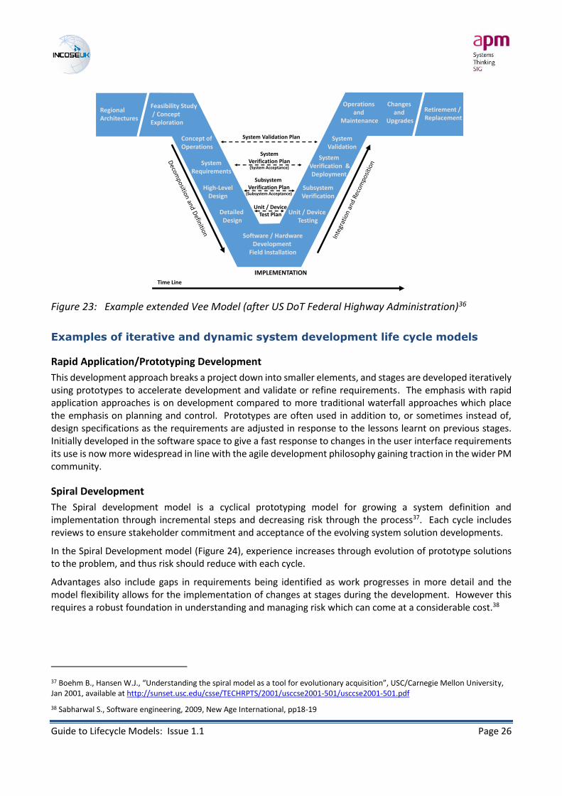
There is no single definition of a Vee Model, but the basic underlying philosophies are illustrated in Figure 23. This example, taken from the US Department of Transport Federal highways Administration36, is also an illustration of an extended Vee Model – these include upstream concept definition phases and downstream operations and retirement phases.
For further details on the Vee Model, refer to the SEHBK.
35 SEHBK, Section 3, pages 27 & 28, 31
36 US Department of Transport Federal Highways Administration Office of Operations, “Designing for Transportation Management and Operations: A Primer”, Chapter 2: Putting it into Action – Policies and Procedures, http://www.ops.fhwa.dot.gov/publications/fhwahop13013/ch2.htm [accessed 16th Sept 2014]
Requirements Analysis
Problem Identification
Feasibility Study
Design
Development and Testing
Implementation
Integration and Verification
Acceptance and Validation
Waterfall ModelNon-returnable sequential flowbetween phases
Modified WaterfallLimited feedback added between phases
Actual phases will be dependent on scenario
In-Service and Disposal
Guide to Lifecycle Models: Issue 1.1 Page 26
Figure 23: Example extended Vee Model (after US DoT Federal Highway Administration)36
Examples of iterative and dynamic system development life cycle models
Rapid Application/Prototyping Development
This development approach breaks a project down into smaller elements, and stages are developed iteratively using prototypes to accelerate development and validate or refine requirements. The emphasis with rapid application approaches is on development compared to more traditional waterfall approaches which place the emphasis on planning and control. Prototypes are often used in addition to, or sometimes instead of, design specifications as the requirements are adjusted in response to the lessons learnt on previous stages. Initially developed in the software space to give a fast response to changes in the user interface requirements its use is now more widespread in line with the agile development philosophy gaining traction in the wider PM community.
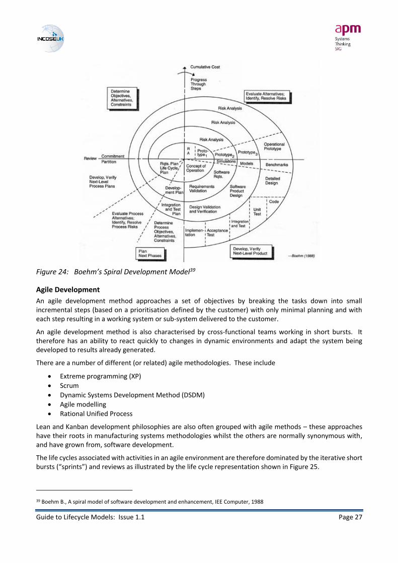
Spiral Development
The Spiral development model is a cyclical prototyping model for growing a system definition and implementation through incremental steps and decreasing risk through the process37. Each cycle includes reviews to ensure stakeholder commitment and acceptance of the evolving system solution developments.
In the Spiral Development model (Figure 24), experience increases through evolution of prototype solutions to the problem, and thus risk should reduce with each cycle.
Advantages also include gaps in requirements being identified as work progresses in more detail and the model flexibility allows for the implementation of changes at stages during the development. However this requires a robust foundation in understanding and managing risk which can come at a considerable cost.38
37 Boehm B., Hansen W.J., “Understanding the spiral model as a tool for evolutionary acquisition”, USC/Carnegie Mellon University, Jan 2001, available at http://sunset.usc.edu/csse/TECHRPTS/2001/usccse2001-501/usccse2001-501.pdf
38 Sabharwal S., Software engineering, 2009, New Age International, pp18-19
Regional Architectures
Feasibility Study/ Concept
Exploration
Concept of Operations
SystemRequirements
High-LevelDesign
Detailed Design
Software / HardwareDevelopment
Field Installation
Unit / Device Testing
SubsystemVerification
SystemVerification &Deployment
SystemValidation
Operations and
Maintenance
Changes and
Upgrades
Retirement / Replacement
IMPLEMENTATION
Unit / DeviceTest Plan
Subsystem Verification Plan
(Subsystem Acceptance)
SystemVerification Plan(System Acceptance)
System Validation Plan
Time Line
Guide to Lifecycle Models: Issue 1.1 Page 27
Figure 24: Boehm’s Spiral Development Model39
Agile Development
An agile development method approaches a set of objectives by breaking the tasks down into small incremental steps (based on a prioritisation defined by the customer) with only minimal planning and with each step resulting in a working system or sub-system delivered to the customer.
An agile development method is also characterised by cross-functional teams working in short bursts. It therefore has an ability to react quickly to changes in dynamic environments and adapt the system being developed to results already generated.
There are a number of different (or related) agile methodologies. These include
• Extreme programming (XP)
• Scrum
• Dynamic Systems Development Method (DSDM)
• Agile modelling
• Rational Unified Process
Lean and Kanban development philosophies are also often grouped with agile methods – these approaches have their roots in manufacturing systems methodologies whilst the others are normally synonymous with, and have grown from, software development.
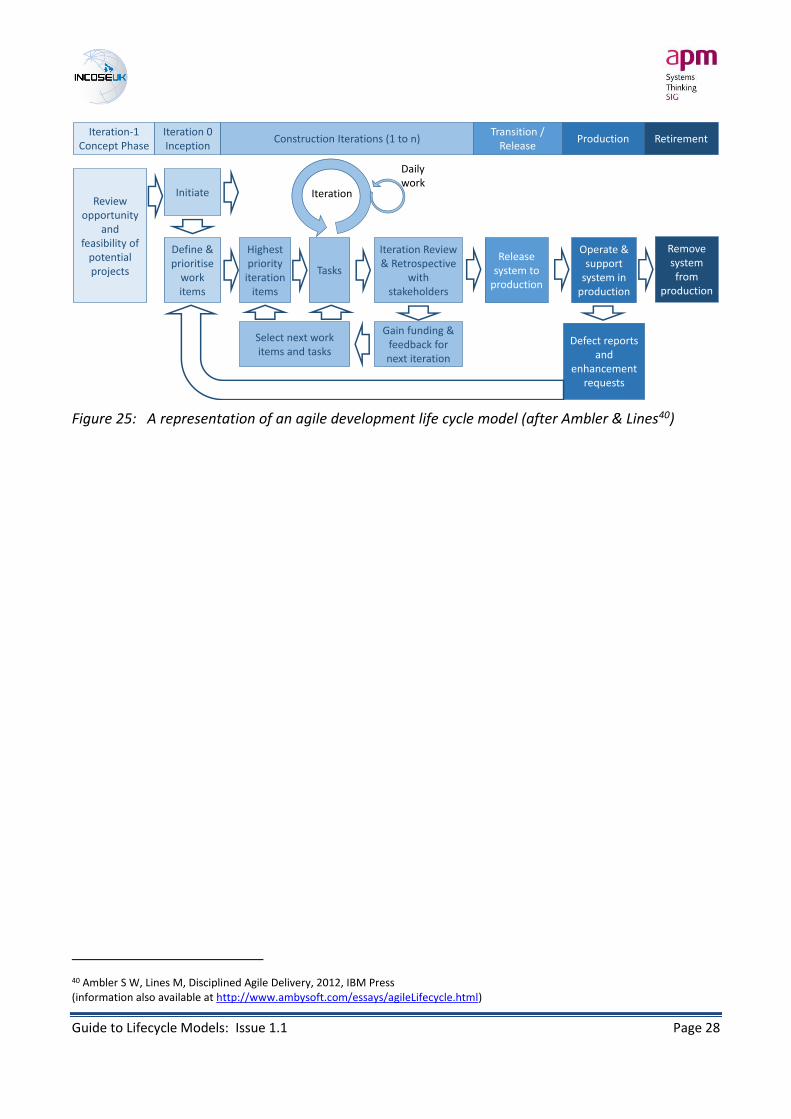
The life cycles associated with activities in an agile environment are therefore dominated by the iterative short bursts (“sprints”) and reviews as illustrated by the life cycle representation shown in Figure 25.
39 Boehm B., A spiral model of software development and enhancement, IEE Computer, 1988
Guide to Lifecycle Models: Issue 1.1 Page 28
Figure 25: A representation of an agile development life cycle model (after Ambler & Lines40)
40 Ambler S W, Lines M, Disciplined Agile Delivery, 2012, IBM Press (information also available at http://www.ambysoft.com/essays/agileLifecycle.html)
Iteration-1Concept Phase
Iteration 0Inception
Construction Iterations (1 to n)Transition /
ReleaseProduction Retirement
Review opportunity
and feasibility of
potential projects
Initiate
Define & prioritise
work items
Highest priority
iteration items
Tasks
Iteration
Daily work
Iteration Review & Retrospective
with stakeholders
Gain funding & feedback for next iteration
Select next work items and tasks
Release system to
production
Operate & support
system in production
Remove system from
production
Defect reports and
enhancement requests
Guide to Lifecycle Models: Issue 1.1 Page 29
7. Category relationships and product life spans
In this chapter we review how the scenarios, approaches and models combine, and how where overlaps and frictions can arise between SE and P3M processes, including the relationship between the product life span and the project life cycle.
Project life cycles and product life spans
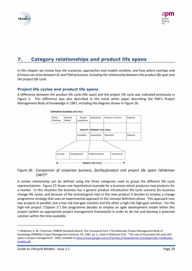
A difference between the product life cycle (life span) and the project life cycle was indicated previously in Figure 2. This difference was also described in the initial white paper describing the PMI’s Project Management Body of Knowledge in 1987, including the diagram shown in Figure 26.
Figure 26: Comparison of corporate business, facility/product and project life spans (Wideman 1987)41
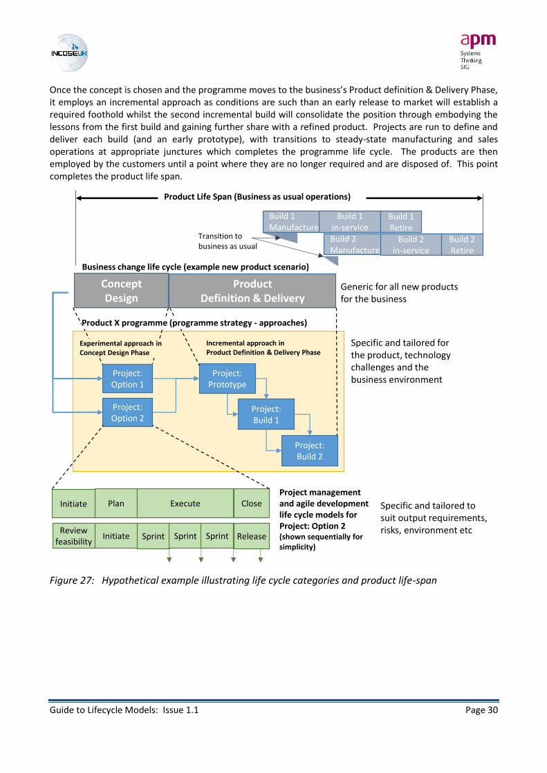
A similar relationship can be defined using the three categories used to group the different life cycle representations. Figure 27 shows one hypothetical example for a business which produces new products for a market. In this situation the business has a generic product introduction life cycle scenario (its business change life cycle), and because of the technological risks in this new product it decides to employ a change programme strategy that uses an experimental approach in the concept definition phase. This approach runs two projects in parallel, one a low-risk low-gain solution and the other a high-risk high-gain solution. For the high-risk project (“Option 2”) the programme decides to employ an agile development model within this project (within an appropriate project management framework) in order to de-risk and develop a potential solution within the time available.
41 Wideman, R. M., Chairman, PMBOK Standards Board, The Framework Part 1 The Rationale, Project Management Body of Knowledge (PMBOK), Project Management Institute, PA, 1987, p1-1., cited in Wideman R.M., “The role of the project life cycle (life span) in project management”, 2004, available at https://www.google.com/url?q=http://maxwideman.com/papers/plc-models/plc-models.pdf
CORPORATE BUSINESS LIFE CYCLE
PolicyPlanning
IdentifyNeeds
ProjectCompletion
Realization Product in service Disposal
Feasibility Acquisition Operation Disposal
FACILITY / PRODUCT LIFE CYCLE
Concept Development Implementation Termination
PROJECT LIFE CYCLE
Guide to Lifecycle Models: Issue 1.1 Page 30
Once the concept is chosen and the programme moves to the business’s Product definition & Delivery Phase, it employs an incremental approach as conditions are such than an early release to market will establish a required foothold whilst the second incremental build will consolidate the position through embodying the lessons from the first build and gaining further share with a refined product. Projects are run to define and deliver each build (and an early prototype), with transitions to steady-state manufacturing and sales operations at appropriate junctures which completes the programme life cycle. The products are then employed by the customers until a point where they are no longer required and are disposed of. This point completes the product life span.
Figure 27: Hypothetical example illustrating life cycle categories and product life-span
Business change life cycle (example new product scenario)
Project: Option 1
Project: Option 2
Experimental approach in Concept Design Phase
Project: Prototype
Project: Build 1
Project: Build 2
Incremental approach in Product Definition & Delivery Phase
Product X programme (programme strategy - approaches)
Initiate Plan Execute CloseProject management and agile development life cycle models for Project: Option 2(shown sequentially for simplicity)
Review feasibility
Initiate Sprint Sprint Sprint Release
Concept Design
Product Definition & Delivery
Build 1 Manufacture
Build 1 in-service
Build 1 Retire
Build 2 Manufacture
Build 2 in-service
Build 2 Retire
Product Life Span (Business as usual operations)
Transition to business as usual
Generic for all new products for the business
Specific and tailored for the product, technology challenges and the business environment
Specific and tailored to suit output requirements, risks, environment etc

Guide to Lifecycle Models: Issue 1.1 Page 31
8. Governance and feedback mechanisms
In this chapter we explore how PM and SE life cycle representations underpin aspects of governance and provide a decision framework, particularly through the use of stage gates.
The life cycle as a governance and decision framework
Both SE and P3M life cycles are an important aspect of the governance mechanism for undertaking any change initiative and/or developing a system-of-interest. The life cycle is recognised as one of the key areas of governance in P3M and SE as it
provides the structure that underpins delivery42
and
a framework within which organization management has high-level visibility and control of Project and Technical processes43.
A key focus in programme management is in the management of uncertainty: original assessments will become more reliable and accurate as the programme proceeds. However it is not advisable to commit large levels of resource if the outcome is uncertain. A programme life cycle provides a risk-based framework that balances the commitment of resource with the degree of certainty available44.
Portfolio definition is dependent on the existence or establishment of a business change life cycle to underpin the management control practice in the delivery of the portfolio45. A business change life cycle controls the delivery of all change initiatives or categories of initiative (projects or programmes), and this is recorded in the definition of the Portfolio Management Framework. The business change life cycle provides a basis for governance oversight and ensuring that activities in the portfolio are monitored and reviewed consistently.
Portfolio Management ensures the effective and consistent use of a business change lifecycle which provides a review of the continued viability and business value of initiatives…46
42 APMBOK+, Governance, available at http://www.knowledge.apm.org.uk/bok/governance [accessed 17th September 2014]
43 ISO15288:2008 within SEHBK, p21
44 Gower Handbook of Programme Management, 2006, Reiss G. et al, Aldershot: Gower
45 Management of Portfolios, 2011, The Stationery Office (p71-72)
46 Ibid, p16
Guide to Lifecycle Models: Issue 1.1 Page 32
Programme tranches and project stages
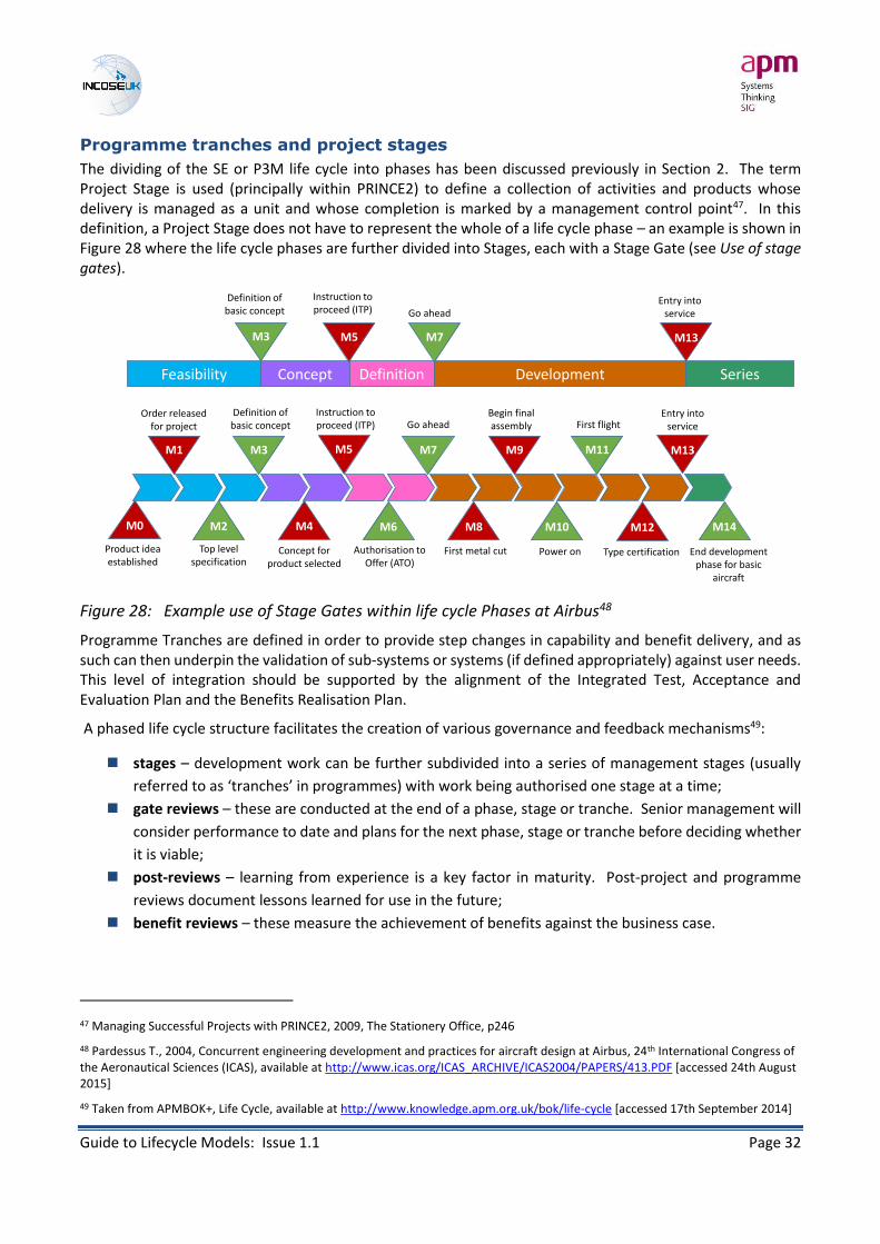
The dividing of the SE or P3M life cycle into phases has been discussed previously in Section 2. The term Project Stage is used (principally within PRINCE2) to define a collection of activities and products whose delivery is managed as a unit and whose completion is marked by a management control point47. In this definition, a Project Stage does not have to represent the whole of a life cycle phase – an example is shown in Figure 28 where the life cycle phases are further divided into Stages, each with a Stage Gate (see Use of stage gates).
Figure 28: Example use of Stage Gates within life cycle Phases at Airbus48
Programme Tranches are defined in order to provide step changes in capability and benefit delivery, and as such can then underpin the validation of sub-systems or systems (if defined appropriately) against user needs. This level of integration should be supported by the alignment of the Integrated Test, Acceptance and Evaluation Plan and the Benefits Realisation Plan.
A phased life cycle structure facilitates the creation of various governance and feedback mechanisms49:
stages – development work can be further subdivided into a series of management stages (usually
referred to as ‘tranches’ in programmes) with work being authorised one stage at a time;
gate reviews – these are conducted at the end of a phase, stage or tranche. Senior management will
consider performance to date and plans for the next phase, stage or tranche before deciding whether
it is viable;
post-reviews – learning from experience is a key factor in maturity. Post-project and programme
reviews document lessons learned for use in the future;
benefit reviews – these measure the achievement of benefits against the business case.
47 Managing Successful Projects with PRINCE2, 2009, The Stationery Office, p246
48 Pardessus T., 2004, Concurrent engineering development and practices for aircraft design at Airbus, 24th International Congress of the Aeronautical Sciences (ICAS), available at http://www.icas.org/ICAS_ARCHIVE/ICAS2004/PAPERS/413.PDF [accessed 24th August 2015]
49 Taken from APMBOK+, Life Cycle, available at http://www.knowledge.apm.org.uk/bok/life-cycle [accessed 17th September 2014]
Feasibility Concept Definition Development Series
Definition of basic concept
M0
M3 M5 M7
Instruction to proceed (ITP) Go ahead
M13
Entry into service
M1
M2
M3
M4
M5
M6
M7
M8
M9
M10 M14
M11
M12
M13
Definition of basic concept
Instruction to proceed (ITP) Go ahead
Entry into service
Order released for project
Product idea established
Top level specification
Concept for product selected
Authorisation to Offer (ATO)
First metal cut Power on Type certification End development phase for basic
aircraft
Begin final assembly First flight

Guide to Lifecycle Models: Issue 1.1 Page 33
Use of stage gates
A decision gate is an approval event and decision point in the life cycle where the project or programme has to demonstrate continuing viability and the required level of maturity. Entry and exit criteria are established for each gate50, and general objectives of each gate (whether they are for projects, programmes or system developments) include:
Are current elaborations of business and technical baselines still acceptable? Are they still consistent
with the organisation objectives?
Are all aspects of the undertaking synchronised (to the required degree) and at the necessary level of
maturity?
Is the next step achievable and defined, with acceptable levels of risk?
Stage gates can be linked to release of funding and/or approvals for expenditure for the next stage, and/or payments to suppliers.
Whatever the different phases or stages in the life cycle, each stage should conclude with a Stage Gate Review. This is a go/no go decision point that has to be passed before the project can move to the next stage. Examples of Stage Gates in the life cycle are shown in Figure 28 and Figure 29 (note that Figure 29 is the life cycle shown previously in Figure 6). Gates are important for a wide range of SE and Project processes including organisational governance, management control, stakeholder engagement, risk management, quality management, requirements management and financial management, and thus again illustrate how life cycles, with corresponding stage gates, underpin all aspects of SE and P3M.
Further information can be found on Stage Gates from SEHBK (Section 3.2.2), APMBOK (Section 1.1), PRINCE2 (Managing Stage Boundaries process)13 and the Gower Handbook on Programme Management (pp132-136)44.
Figure 29: Example use of Stage Gates within the life cycle (©Cummins Turbo Technologies)18
50 See also Table 2
IDEACONCEPT
DESIGN BUILD VALIDATE RELEASE
TECHNOLOGY DEFINITIONTECHNOLOGY DEFINITION PRODUCT DEFINITIONPRODUCT DEFINITION
CONCEPTDESIGN VERIFY
VALIDATELAUNCH
E0E0 G1G1 G1G1 G2G2 G3G3 G4G4
IdeaDefined
TargetsSet
ConceptSelected
PrototypeDesignReady
PrototypeTesting
Completed
Design ValidationCompleted
M0M0M1M1 M2M2 M3M3 M4M4 M5M5Charter
Approval ConceptDefinitionComplete
StableDesign
AlphaSystemBuild
Complete
BetaSystemBuild
Complete
LaunchApproval
Product Preceding Technology (PPT) Value Product Introduction (VPI)
Guide to Lifecycle Models: Issue 1.1 Page 34
9. Comparisons of SE and P3M definitions
In this chapter we consider the different perspectives between the SE and PM disciplines, and how combining representations could be used to provide an integrated systems view of the programme life cycle.
SE and P3M perspectives
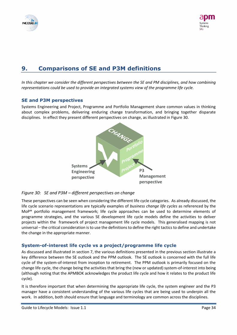
Systems Engineering and Project, Programme and Portfolio Management share common values in thinking about complex problems, delivering enduring change transformation, and bringing together disparate disciplines. In effect they present different perspectives on change, as illustrated in Figure 30.
Figure 30: SE and P3M – different perspectives on change
These perspectives can be seen when considering the different life cycle categories. As already discussed, the life cycle scenario representations are typically examples of business change life cycles as referenced by the MoP® portfolio management framework; life cycle approaches can be used to determine elements of programme strategies, and the various SE development life cycle models define the activities to deliver projects within the framework of project management life cycle models. This generalised mapping is not universal – the critical consideration is to use the definitions to define the right tactics to define and undertake the change in the appropriate manner.
System-of-interest life cycle vs a project/programme life cycle
As discussed and illustrated in section 7, the various definitions presented in the previous section illustrate a key difference between the SE outlook and the PPM outlook. The SE outlook is concerned with the full life cycle of the system-of-interest from inception to retirement. The PPM outlook is primarily focused on the change life cycle, the change being the activities that bring the (new or updated) system-of-interest into being (although noting that the APMBOK acknowledges the product life cycle and how it relates to the product life cycle).
It is therefore important that when determining the appropriate life cycle, the system engineer and the P3 manager have a consistent understanding of the various life cycles that are being used to underpin all the work. In addition, both should ensure that language and terminology are common across the disciplines.
P3 Managementperspective
SystemsEngineeringperspective

Guide to Lifecycle Models: Issue 1.1 Page 35
This is especially important when discussing Stages and Phases where the two terms may mean different things to the two communities – as discussed in Terminology and Programme tranches and project stages. A Project Manager may be co-ordinating a Stage completion (based on the project stage objectives) whilst a System Engineer considers themselves part-way through the Development Stage (of the generic SE Life Cycle shown in Table 2).
Commonality of descriptions
On close inspection there is a great deal of synergy and commonality between the two disciplines in the determination of the individual phases of the life cycles. Generic representations are consistent, translatable and transferrable. P3 and P3M life cycles typically contain less granularity as they are more focused on the need to underpin the control and governance aspects of the work, as opposed to helping to provide a detailed definition of the manner and means through which the development work will be undertaken.
It must be therefore noted that this detailed understanding of the development work to be undertaken is intrinsically important to the P3 Manager. It will underpin the means by which projects and programmes will be structured and planned (e.g. determining the Project Approach in a PRINCE2® Product Based Planning environment). This aspect of the levels of overlap and dependency of SE and P3 processes is addressed and developed further in “Guide to SE and P3M Processes”.
Use of Vee Model to depict programme management strategy
The use of SE life cycle depictions do permeate through PM literature and process guidance. For example, reference is made to waterfall. Vee and Spiral models in the Life Cycle section of the APMBOK. Another example is the depiction of the strategic context of benefits realisation within a programme depicted by MSP51.
Figure 31: Programme Management as a Vee Model (encompassing SE elements)
Reinforced by an appreciation that benefits management and realisation is allied to, and complementary with, system verification and validation (when the programme is considered as a system itself), it is possible to
51 Managing Successful Programmes, 2011, The Stationery Office, p66
Implementation
Organisational Drivers Strategic Objectives
Programme Vision
User Requirements
Programme Blueprint (Operational Architecture)
Programme Plan
System Requirements
System Architecture
Project Plans System Elements
Integrated System
Verified System
Capability Elements
Outcomes
Operational Capability (Validated System)
Benefits
Stakeholder Needs andRequirements Definition
Programme Planning
Project Planning
Programme Definition
System RequirementsDefinition
Architecture Definition
Project Delivery
Integration
Verification
Programme Delivery
ChangeManagement
Benefits Realisation
Validation
Transition
Operation, Maintenance
CapabilityDelivery
Business Analysis
Design Definition System Analysis
Project Controls

Guide to Lifecycle Models: Issue 1.1 Page 36
expand this to encompass SE elements as shown in Figure 31. The associated guide “Integration of Life Cycle Representations” develops this integrated model further.
Guide to Lifecycle Models: Issue 1.1 Page 37
10. Life cycle selection and tailoring
In this chapter we consider what has to be taken into account when selecting life cycle representations, and how these are to be used as a foundation for defining and communicating the work to be undertaken.
Align scenarios with strategic direction
Change life cycle scenarios are defined by the business according to the environment the business or organisation operates in, the nature of the market place, sources of competitive advantage, quality and safety requirements, the culture of the business itself, and the change that is required to be undertaken.
Businesses that are product based will define new-product life cycles that reflect the product life span, market conditions and key success factors52. These business will also undergo transformational change at some point, as will other organisations. For this change challenge they will need to define a transformational strategy that suits the organisational culture and principles and the nature of the change journey to be undertaken.
Above all, the selection of a business change life cycle scenario is a strategic decision to be undertaken by the senior management board. But these individuals need to be guided in the determination of this strategic direction by the needs of the P3M and SE communities who have to execute the specific changes within this structure – the business change life cycle needs to be aligned with, and enable, the approaches and models that will support the change.
Selecting the life cycle approach
The life cycle approach depends on the project complexity, the budget, the appetite for risk and the overall business model. This section is intended to briefly cover some of the main life cycle approaches which can then be tailored to fit.
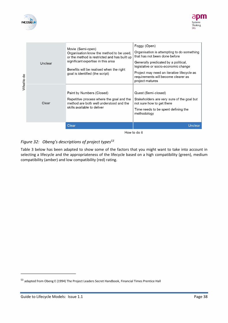
It is well recognised that there are different types of project. Obeng’s classifications of project types, shown in Figure 32, are useful to help gain an understanding of the types of project and understand how a different lifecycle approach might be taken.
The alignment between some of the project types and approaches is relatively clear, for example you might want to select a base life cycle approach for a ‘paint by numbers’ project as it is good for defined problems and stable technologies. For the other problem types the requirement to select and tailor the right lifecycle approach will involve a further assessment of the project. Experimental approaches work well when the ‘what’ is unknown but if it is a ‘movie’ project and the ‘how’ is known then there might be an imperative to get a solution to market in which case an evolutionary life cycle might be selected. In order to select the right life cycle you need to understand the type of project, the types of risk held by the project and the risk appetite of the organisation.
52 Grant R.M., Contemporary strategy analysis, 1998 3rd Ed., Oxford: Blackwell Publishers, p251-
Guide to Lifecycle Models: Issue 1.1 Page 38
Figure 32: Obeng’s descriptions of project types53
Table 3 below has been adapted to show some of the factors that you might want to take into account in selecting a lifecycle and the appropriateness of the lifecycle based on a high compatibility (green), medium compatibility (amber) and low compatibility (red) rating.
53 adapted from Obeng E (1994) The Project Leaders Secret Handbook, Financial Times Prentice Hall

Guide to Lifecycle Models: Issue 1.1 Page 39
Table 3: Life cycle approach selection table (adapted from Adcock & Farncombe 200912)
The influence of risk
Risk and its management plays a significant part in the selection of the appropriate life cycle development and management model for undertaking projects54. The life cycle stages, particularly where programme or project management is aligned with risk management, are in turn associated with sources of common risks, and it is acknowledged that it is desirable to address risk earlier rather than later, before commitments are made and later change becomes increasing expensive.
Whilst it is focused on IT environments and not a definitive guide, the comparison made by Joanna Rothman55 in Table 4 provides an illustration of risk-based selection criteria between sequential and iterative development models.
Other considerations include the stability of requirements (as also discussed in Table 4), the timescales involved, the level of integration and co-location of the project team, the scale of the project, the scope and influence of stakeholders and critical resources. However these considerations are also in essence sources of risk – hence the influence of risk on the selection and definition of the project development life cycle model.
54 Chapman C & Ward S, Project risk management: Processes, techniques and insights, John Wiley & Sons: Chichester, 1997, pp13-24
55 Rothman J., What Lifecycle? Selecting the Right Model for Your Project, Cutter IT Journal, Vol 21, #5, May 2008, available at http://www.jrothman.com/2008/01/what-lifecycle-selecting-the-right-model-for-your-project/

Guide to Lifecycle Models: Issue 1.1 Page 40
Table 4: An example of development model selection based on consideration of risk55
Life cycle type Examples Strengths and necessary conditions for success
Project drivers (in order)
Prognosis for success
Serial Waterfall, phase-gate
• Manages cost risk (if management uses the phase gates)
• Known and agreed-upon requirements
• Well-understood system architecture
• Requirements stable over project
• Project team stable over project
1. Feature set
2. Low defects
3. Time to release
Successful with feedback
Iterative Spiral, evolutionary prototyping
• Manages technical risk
• Ever-evolving requirements
1. Feature set
2. Low defects
3. Time to release
Successful assuming the finishing parts are planned and occur
Incremental Design to schedule, staged delivery
• Manages schedule risk
• Can absorb small requirements changes but not so many changes that the architecture would have to change
1. Time to release
2. Low defects
3. Feature set
Likely to be successful if you actually follow the lifecycle
Iterative / incremental
Agile (such as Scrum, XP)
• Manages both schedule and technical risk
• Difficult to do well without a collocated integrated team
1. Time to release
2. Feature set
3. Low defects
Likely to be successful if you actually follow the lifecycle
Ad hoc Code and fix 1. Time to release
2. Feature sets
3. Low defects
Unsuccessful
Follow, but monitor
Once a life cycle representation has been selected it provides a firm foundation for the manner and means by which the work is structured. However, as with the selection of any set of methodologies, that life cycle selection has to ensure that it is appropriate, and remains so. Geoff Reiss56 has described some potential dangers:
“I do believe that a methodology has as many dangers as benefits. The benefits are that a set of guidelines are established that are aimed to bring some order to the project life cycle. […] One danger is that the methodology is inappropriate. It is not uncommon for a team of enthusiastic but green graduates or a team of near-retirement project people to be given the task of designing the project life cycle. The methodology is then rigidly followed by the project teams because it is the approved way of doing things.
Another danger is that the method becomes inappropriate as time passes, new techniques are developed and the company structure changes.
Methodologies need to be followed but they need to be reviewed from time to time.”
56 Reiss G., Programme Management Demystified, 1996, London: Spon Press (p113)
Guide to Lifecycle Models: Issue 1.1 Page 41
Combine, but do not confuse
The discussions included in this guide are based on general, idealised and conceptual situations or frameworks. Practical applications will involve combined and tailored solutions to suit the situation. Life cycle representations can be successfully combined in different ways (noting that the categorisations are defined with a view to facilitate combinations and selections) but this must be done with caution – confusion over life cycles can be a source of failure.
An agile development environment can work within a project or programme management framework (an example of this are the AgilePgM® and AgilePjM® frameworks57), and can be effective when addressing key elements of uncertainty in the early phases of a programme or engaging with key stakeholders to achieve quick wins or early buy-in (for example the use of rapid prototyping. Projects based on agile and sequential development methods can also act in parallel within the same programme, but significant care must be taken in separating the two projects (and managing the relationships between them) as they require different project environments and potential cross-contamination will pose a clear danger to each project.
Don’t select evolutionary iterative approaches and models in stable conservative organisations with long-term life cycles and markets if it is not appropriate. If it is appropriate, then consider the transformational changes needed to people, culture, organisation and behaviours.
There is much more emphasis on governance in the P3M Suite, and these frameworks are initiated early in the programme or project life cycles. This can create a tension between a focus on governance at the expense of time spent creatively scoping the problem, and is a potential cause of agile vs ‘traditional’ PM conflicts.
The selection of the life cycle will be a significant factor in the success of the undertaking. It facilitates discussion and analysis that, when combined with P3M and SE techniques, can develop a deeper understanding of the problem faced and its complexities. However the level of endeavour applied must be appropriate to the nature and scale of the problem faced – not every project is complex or facing significant risks.
57 Refer to the Dynamic Systems Development Method (DSDM) frameworks at http://www.dsdm.org