guide to structural evaluation of existing timber structures
TRANSCRIPT

TFEC 3-2019
Guide to
Structural Evaluation of
Existing Timber Structures
January 2019

TFEC 3-2019 Page 2
This document is intended to be used by experienced engineers to provide guidance in evaluating existing timber structures. It should not be used to evaluate a timber structure without the services of a trained professional. This document is not intended to supplant the requirements of the building code or replace the judgement of the engineer. The Timber Frame Engineering Council and the Timber Framers Guild assume no liability for the use or misuse of this document.
TFEC-3 Committee:
Jim DeStefano, P.E., AIA, F.SEI chairman Ron Anthony Tom Nehil, P.E. Jaret Lynch, P.E.
Acknowledgements
The committee thanks Robert Falk of the Forest Products Laboratory, Richard Schmidt of Fire Tower
Engineered Timber and Derek Trelstad of Robert Silman Associates for their review and comments on
the draft document.
Copyright © 2018 Timber Frame Engineering Council
TFEC 3-2019 Page 3
Table of Contents
Introduction 4
Deterioration and Impairment 5
Fire Damage 9
Condition Assessment 10
Structural Evaluation 13
Material Strength Testing 14
Load Testing 15
Species Identification 17
Timber Grading 20
Reference Design Values and Allowable Stresses 29
Interpretation of Findings 31
Appendix A – Timber Grading Rules 33
Further Reading 37
TFEC 3-2019 Page 4
Introduction
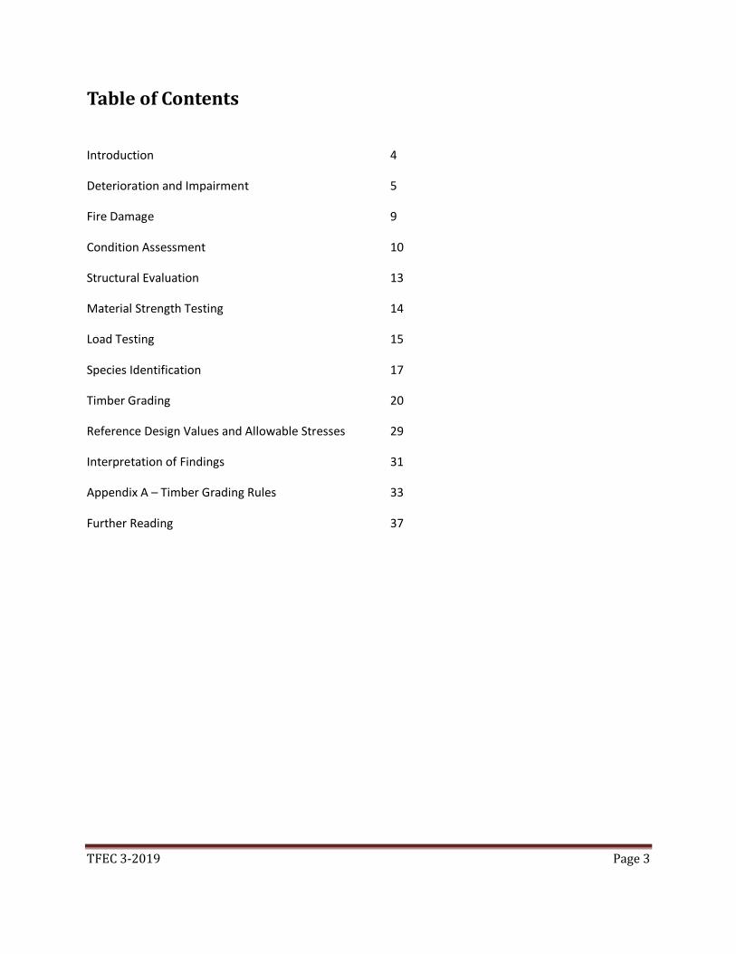
Man has been building timber structures for over 4,000 years throughout Europe and Asia. In North America, timber structures have been built since the first Europeans arrived 400 years ago. Consequently, there are thousands of older timber structures still in service. If maintained and protected from biological agents of destruction, the service life of a timber structure is unlimited. Timber construction is differentiated from its much younger cousin, light-frame wood construction (commonly referred to as stick framing), by the size of the members. While light-frame wood construction is made up of dimensional lumber or manufactured I-joists, timber structures are fashioned from sawn or hewn timbers 5”x 5” and larger. When restoring or renovating an older timber structure, or when adapting it to a new use, it is often necessary to evaluate the structural integrity and load carrying capacity of the timbers. When structural deficiencies are identified, structural remediation may be in order. If the structural evaluation is based on overly conservative or unrealistic assumptions, the resulting remediation program may be excessively costly and may result in unsightly and unnecessary alterations to the timber structure.
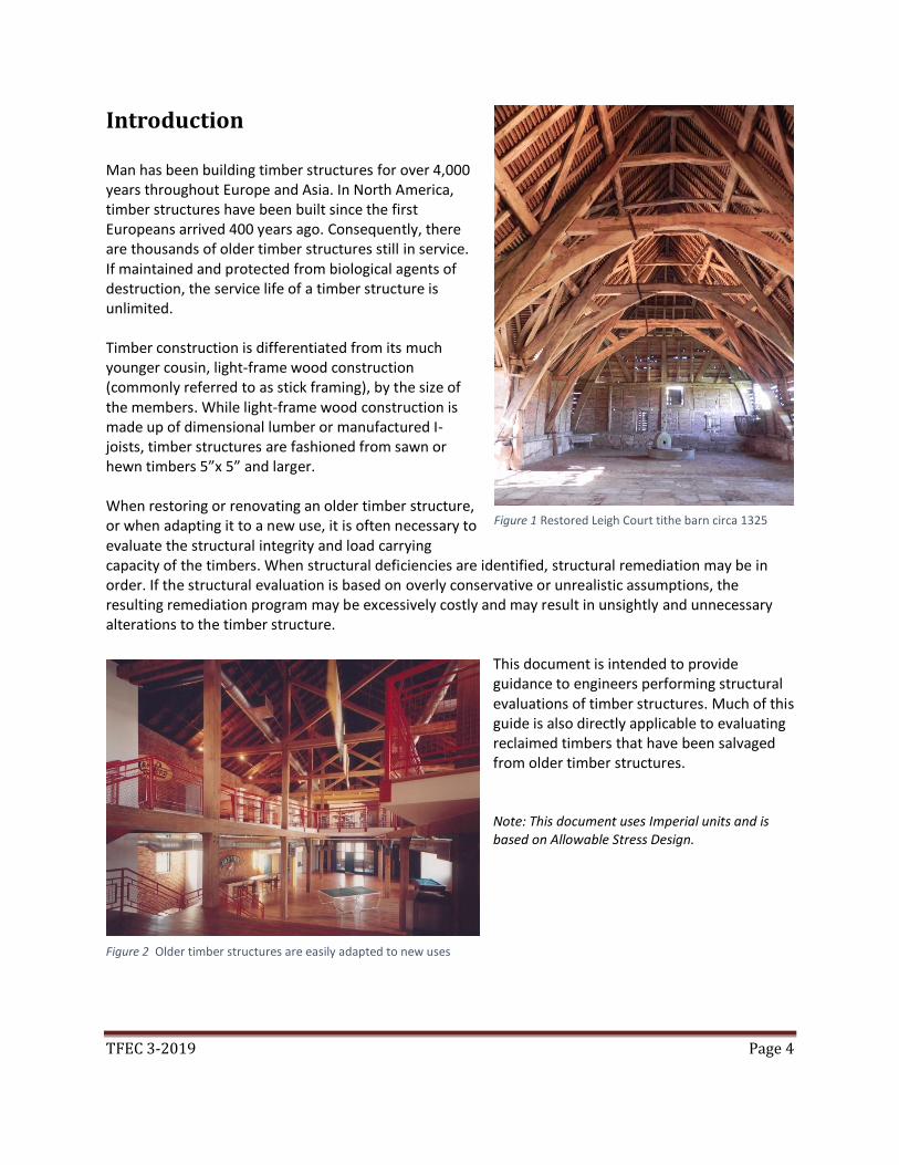
This document is intended to provide guidance to engineers performing structural evaluations of timber structures. Much of this guide is also directly applicable to evaluating reclaimed timbers that have been salvaged from older timber structures. Note: This document uses Imperial units and is based on Allowable Stress Design.
Figure 1 Restored Leigh Court tithe barn circa 1325
Figure 2 Older timber structures are easily adapted to new uses

TFEC 3-2019 Page 5
Deterioration and Impairment It is rare to find on older timber structure that does not exhibit some degree of deterioration that may affect the capacity of the structure. Timber deterioration may be caused by fungal decay, insect infestations, structural overload, or mechanical damage. Misguided repairs can result directly in mechanical damage to the timber or cause moisture related decay. The reduction in structural load resistance associated with timber deterioration, regardless of cause, is referred to as impairment. Fungal Decay: Fungal decay – often simply called decay or rot - is by far the most common type of timber deterioration. Rot is caused by a fungus that feeds on the lignin and cellulous fiber of the wood. There are a variety of rot fungi types. Brown rot, is the most common form of decay, while wet rot and white rot are not uncommon. Dry rot is a form of brown rot, but the term is frequently misused. Precise identification of fungi is difficult and not necessary for most projects. All rot fungi require water, warmth, oxygen, and a wood food source to grow and thrive. Consequently, only wet timber will rot. Timbers fully submerged in water will not rot due to the absence of oxygen, while partially submerged timbers will frequently rot just above the water line.
Decay fungi will become dormant and eventually perish if the source of moisture is cut off. Drying time can take anywhere from a few weeks to a few years depending on the drying conditions. In the absence of water some fungi will remain dormant. When water is returned to the wood, fungal growth may resume. Surface molds such as mildew do not affect the structural properties of the timber. Sap-stain fungus, referred to as blue stain, also does not affect the structural properties.
As decay progresses and the rot fungi digest the wood fiber, the infected timber will lose mass and strength. Early stages of decay characterized by discoloration and a soft spongy (punky) surface is referred to as incipient decay. A 10% mass loss associated with incipient decay can result in a significant reduction in mechanical properties of the wood. Advanced decay results in a near total loss of strength.
Figure 3 Discoloration can be a sign of rot
Figure 4 Brown rot

TFEC 3-2019 Page 6
Insect Infestation: There are several species of insects that bore into or feed on wood tissue. In North America, the most common are termites, powder-post beetles, carpenter ants, and carpenter bees. Termites are the most celebrated of the wood destroying insects. In temperate climate zones, subterranean termites are pervasive. Subterranean termites do not nest in wood. They live in colonies that are buried in the ground and have an advanced class society with royalty, worker termites, and soldier termites. They tunnel into a building below ground and climb up into the timber structure within cavities in the foundation or build mud tunnels on the outside of the foundation. They will consume and digest wood tissue as they tunnel along the grain of a timber, taking care to avoid breaking through to the surface of the timber. They leave behind a hollowed-out timber with a thin shell of wood on the outside. Consequently, a termite infested timber is likely to appear perfectly intact from the outside and must be probed to uncover the network of galleries littered with frass (insect feces). Subterranean termite damage usually progresses at a slow rate and the damage tends to be confined to the lower portions of the structure that are close to the ground. It often takes decades for an active termite infestation to do substantial damage. That is not true for termite varieties that are indigenous to tropical climate zones. Drywood termites and Formosan termites are found in the southern United States. These species of termites can do significant damage in a relatively short period of time. Powder post beetle damage is more common than termite damage. Powder post beetles will attack timber in damp spaces such as over a crawl space or basement with an earthen floor. They prefer
hardwood timber and often the damage is limited to the sapwood. Powder post beetle larvae will burrow into a timber from the surface and digest wood fiber as they tunnel through it. When the beetles reach adulthood, they emerge from the timber and lay their eggs on the surface for the cycle to begin again. In contrast to termite damaged timber, timber infected with powder post beetles will be peppered with pin size emergent holes on the surface that ooze a fine powdery frass that is the consistency of flour. The sapwood of the timber will often be soft and punky while the heartwood may be sound.
Figure 5 Termite damaged timber
Figure 6 Powder post beetle damage

TFEC 3-2019 Page 7
Carpenter ants do not eat wood but they like to build their nests in timbers. They prefer wet, partially decayed wood, so carpenter ants are commonly found in timbers that already have rot issues. They will chew through a timber following the grain and discard the wood that they excavate in neat piles of sawdust on the floor. Unlike termite galleries that are filled with frass, carpenter ant galleries are smooth and clean. Carpenter bees also build their nests inside timbers. They will bore a smooth entrance hole, approximately ½ inch dimeter, in the side of a timber that intersects a network of galleries that follow the grain. Carpenter bees are most prevalent in the southern United States. Typically, carpenter bee damage is only found in timbers that are exposed to the exterior.
When evaluating the structural impairment associated with insect damage, the damaged wood is treated as a void in the timber. Mechanical Damage: Insects are not the only species that have been known to do mechanical damage to timbers. Rodents frequently gnaw on timbers to gain access to buildings or nesting sites. In agricultural barns, confined livestock will occasionally chew on structural timbers and
sills. Sometimes the pests walk upright and carry reciprocating saws. In the course of remodeling a structure, tradesmen will sometimes cut through or bore into timbers to accommodate piping or mechanical systems without regard for the structural implications. Timber framing under or adjacent to bathrooms and mechanical rooms are prime targets for this type of mechanical damage. Overloading: Identifying the structural impairment associated with overloading can be challenging. Often the loading history of a structure is not known. Timber mill buildings that previously housed manufacturing operations or warehouse space were often overloaded with heavy equipment or high storage loads. Fractures are a rupture of the wood fibers across the grain and are distinctively different from a seasoning
Figure 7 A timber that has been compromised
Figure 8 Fractured timber due to overloading

TFEC 3-2019 Page 8
check which is parallel to the grain and not caused by structural overloading. Truss bottom chords designed according to early versions of the National Design Specification for Wood Construction (NDS) are prone to tensile failure due to unconservative published allowable stress limits contained therein. Bowstring trusses built during and after World War II are particularly vulnerable to failure. Splits along the grain caused by notching of members subjected to high shear stress can be a cause for concern. Unlike a seasoning check, a split extends through the full thickness of a timber.
Figure 9 Fractured timber
Figure 10 Split in a notched timber
Figure 9 Tension fracture in bottom chord of a bowstring truss

TFEC 3-2019 Page 9
Fire Damage Unlike light-frame wood structures, timber construction tends to perform well in a fire. A char layer forms on the outside of a timber during a fire, protecting the core of the timber. It is not uncommon to find some fire damaged timbers still in service in older structures. In evaluating the residual strength of a fire damaged timber, the char layer can be assumed to have no structural load resistance. The heated zone directly behind the char layer can be assumed to have diminished structural properties. The heated zone is typically about ¼ inch thick. The remaining timber behind the heated zone can usually be assumed to have the same structural properties as if there had been no fire. It is necessary to accurately measure the depth of the char layer and estimate the dimensions of the remaining sound timber below the char layer and heated zone to analyze the residual load carrying capacity. Particular attention needs to be paid to evaluating the fire damage to the connections. Steel bolts and connection hardware should be carefully examined. Since steel readily conducts heat, the wood in contact with steel connectors is often severely charred. Concealed steel connection hardware is typically protected from fire damage by the surrounding wood unless the wood cover is less than the depth of the char layer.
If fire damaged timbers are to remain in service, it is advisable to remove the char layer. Abrasive blasting using baking soda or dry ice is effective at removing the char. If the char layer is more than ½ inch thick, it is often more practical to replace the timber.
Figure 11 Fire damaged timber
Figure 12 Fire damaged barn

TFEC 3-2019 Page 10
Condition Assessment The condition assessment of a timber structure begins with a visual examination to evaluate the extent of deterioration and to identify signs of structural distress. Areas where persistent roof leaks are evident or where timbers are pocketed into a masonry wall are the most susceptible to rot. An awl is a simple and indispensable tool for probing the surface of a timber to identify the depth and extent of deterioration. An awl is also useful in identify the extent of insect damage. Any portion of the wood that can be penetrated with modest pressure on an awl should be assumed to have negligible strength.
There may be deterioration present within the core of a timber that cannot be seen and is too deep to probe with an awl. Sounding with a hammer can be effective at identifying areas where hidden deterioration exists. The sound that the timber makes when struck with the hammer is an indication of the soundness of the timber. A dull thud indicates that there may be internal deterioration which tends to dampen high frequency sound waves traveling through a timber. The hammer sounding technique is highly subjective but may signal to the investigator the presence of voids or hidden deterioration. Some form of nondestructive evaluation (NDE) may be warranted if hidden deterioration is suspected. There are some sophisticated NDE systems such as ultrasonic stress-wave measurement that have been used with limited success in evaluating deteriorated timbers but resistance drilling is the preferred method.
Figure 13 An awl is used to probe for rot.
Figure 14 A rock pick can be used for sounding

TFEC 3-2019 Page 11
Resistance drilling creates a small diameter hole (typically 1/8”) in the timber and the torque required to advance the drill bit is measured and plotted versus depth. Rotted or insect damaged areas clearly show up although regions of incipient decay are often difficult to detect in softwood species.
It is worthwhile to measure the moisture content of the timbers. A high moisture content (above 30%) is an indicator that conditions are conducive to rot deterioration. Note that portions of a timber embedded in or running adjacent to masonry walls are prone to moisture related decay while at the same time being difficult to access with a moisture meter. The structural properties of timber vary with moisture content. Published allowable stress values are based on green timbers in dry service conditions. Fully seasoned timbers have a higher strength and higher allowable stress values can be justified if the actual moisture content is known.
Figure 15 A resistance drill is a useful tool for identifying deterioration hidden below the surface
Figure 16 Hand held moisture meter

TFEC 3-2019 Page 12
Signs of structural distress such as fractured or deflected timbers should be identified and documented. Particular attention should be paid to connections and joinery since that is where most structural failures initiate.
Seasoning checks are often misidentified as structural defects. Checks are ordinary timber features and are not defects. No reduction in design bending strength is warranted for a checked timber beyond the reductions already incorporated into the Building Code. Checks typically do not require remediation unless the checks affect the performance of connections. Misguided remediation of seasoning checks, such as applying bolted steel straps across the check, can lead to splitting of a timber during subsequent moisture cycles. Filling checks with epoxy is also ill-advised since it can lead to moisture entrapment and subsequent decay.
Figure 17 Shear failure in the tenon (relish failure) of a rising brace
Figure 18 Seasoning checks are not material defects

TFEC 3-2019 Page 13
Structural Evaluation In the structural evaluation of an existing timber structure that has been in service for decades, the first step should always be an assessment of the structure’s performance. If the structure is reasonably free from damage or deterioration and has been safely supporting the imposed loads with no sign of structural distress, and no change of use is anticipated that would impose greater loads than have been carried in the past, there is usually no need to embark on a detailed structural analysis or to consider structural remediation. It should be noted that the majority of timber frame structures were built before the adoption of local or state building codes and there is ordinarily no requirement for them to meet the current code. The National Design Specification for Wood Construction (NDS) is a reliable standard for the structural design of new timber structures but is not a good standard for predicting the actual behavior or adequacy of existing structures. There is a wide variation in strength properties of timber classified as a particular grade. The published allowable stress values are calculated based on the weakest 5% of timbers of a given species, and reference design values are based on the worst defects permitted within a given grade. Consequently, the published reference design values are very conservative for most of the timbers that are in service. For adaptive reuse of an older timber structure where the new use has higher loading requirements than the previous use, a structural analysis is appropriate. Older timber barn frames are frequently deconstructed and relocated to a different geographic region with very different occupancy, snow, wind, or seismic load requirements. In such situations, it would be irresponsible to not perform a structural analysis. Significantly deteriorated structural timbers should be replaced or reinforced unless the remaining sound wood is found to be capable of supporting the applied loads. If partially decayed timber is left in service, it is advisable to maintain a moisture content below 20% to prevent decay from progressing. One challenge when determining load carrying capacity of an existing timber structure using analytical techniques is determining what allowable stress values are appropriate. Engineers who are not knowledgeable in evaluating timber structures will often make erroneous assumptions about the timber species and grade that can lead to flawed conclusions and misguided recommendations. For instance, if for expediency, Spruce-Pine-Fir (SPF) No. 2 grade is assumed for analysis purpose but the actual timbers are in fact Southern Pine conforming to a Select Structural grade, the analysis will be overly conservative and significantly undervalue the structure.
Figure 19 Timber barn frame slated for relocation

TFEC 3-2019 Page 14
Materials Strength Testing To make informed decisions about structural adequacy of an individual member, or a group of member types (for example, floor joists), it is important to have some understanding of the material properties. Engineers experienced in evaluation of existing concrete or steel structures for which no design documents or specifications are available are accustomed to extracting samples for materials testing. Timber structures however do not lend themselves readily to this approach. When the need to perform material testing of a timber structure arises, testing protocols developed through ASTM require loading a specimen to failure and using that information as a measure of strength or stiffness of the member(s) of interest. There are several limitations to using ASTM standards for establishing mechanical properties of in-situ timber.
• Removing material for testing is destructive and damages the historic fabric of the structure. It is typically quite expensive to remove full-size members intact without damaging them and needing to replace them.
• The standards were developed for testing new material (recently milled), not older material that has been in service.
• While there are testing protocols for lumber, none exist for timbers. This is traditionally due to the difficulties and cost of conducting numerous large-scale tests on timbers.
• Most standard testing protocols are designed for testing large sample sizes, not individual members or small groups of members.
ASTM standards provide guidance for investigators in determining the appropriate sample size for the testing program to be statistically significant. Typically for solid wood, approximately 60 samples are needed to avoid a reduction in material properties due to a small sample size. It is usually not practical or economically viable to extract that number of timber specimens from a structure. Consequently, the most efficient means of determining mechanical properties of timber in-situ is through visual grading.

TFEC 3-2019 Page 15
Load Testing Load testing is usually the realm of forensic structural engineers, academic researchers, or product manufacturers. Field testing (in-situ) is much less common than laboratory testing. Testing of structural wood components and systems is usually is not practical unless one or more of the following conditions are present:
• High dollar stakes (larger commercial projects)
• Dispute resolution (litigation, insurance claims)
• Collapse/failure (forensic investigation)
• Confirmation of innovative design methods / new materials (mass timber, building code official needs proof, academic research)
• Dynamic loading, verification of analytical models (earthquake, wind, interaction of wood diaphragms with in/out of plane walls)
• Product testing / agency certification (ICC-ES, FPL testing, in-grade testing)
• Determination of FRT or chemical attack of wood materials
Projects involving in-situ assessment of timber do not typically have these motivations. Nonetheless, load testing of in-situ timber can be a valuable tool with which the practicing timber engineer should be familiar. In-situ testing usually involves proof loading a representative portion or portions of the structure to demonstrate that the construction will support the expected load without exceeding a given deflection criteria. Loading a member to a given load provides proof that member, in its current condition, can reliably carry that load. Subsequent changes in the condition of the member, for example decay, can nullify the applicability of the load test to that decayed member. Loading a member to less than the required amount provides scant proof that the member can carry higher loads. Although this sounds like common sense, loading to less than the required load was once commonly cited as a way to prevent damage to the member. By contrast, testing specimens to failure provides direct measurement of the ultimate load carrying capacity but is not practical for most in-situ applications due to the resulting destruction of the member. A prudent engineer analyzes the members in question to know with reasonable certainty that the specimen will not fail during in-situ testing. In other words, do not proof load anything to a level that could reasonably be expected to cause failure. Wood being a natural material is more variable than most of the common construction materials, such as concrete, steel, masonry, glass. The strength and stiffness of wood is affected by species, grain density, moisture content, natural defects, sawing, loading history and decay. Visual assessment of the structure should be performed prior to any in-situ load testing so that an engineering analysis can be used to estimate the expected load capacity and deflection of the test specimen. Ironically, it is often the analysis that is unfeasible, disputed, or lacking certainty that necessitates the testing. Unlike concrete and steel, the NDS does not include a protocol for in-situ proof load testing. Instead, a written testing plan should be prepared by the engineer responsible for the testing. References for in-situ load testing of timber include ASTM E-196, ASTM STP 702, academic research, and numerous FPL publications. The plan should be reviewed and approved by the relevant parties before testing. At a minimum, possible failure modes should be discussed and considered during development of the test plan and the shoring design. Shoring is usually required for in-situ testing. Unlike lab testing, shoring

TFEC 3-2019 Page 16
may be required beyond the limits of the members in question. For example, shoring on an upper story of a building is often continued down to the foundation level and into adjacent spans. Placement of the shores should permit deflection of the structure at each load increment but prevent collapse at all times. Gauges, sensors, and shoring should be configured so that they are safely accessible for adjustment and observation during the test. The weakest point of a wood structure, like other structures, is often at a connection. Be cognizant of this fact and design instrumentation and shoring systems with this in mind. Measurement of the applied load and resulting deflection is essential. Unlike laboratory testing where test abutments and strong floors provide reaction points and reference point for measurement of deflection, in-situ testing requires the creation of these capabilities in the field. Forces applied during in-situ load testing (especially in remote areas) are often influenced by materials on-hand. Reaction frames, anchorage points, dead men, hydraulics, winches, chain hoists, water, vehicles, the self-weight of other portions of the structure, and air pressure are some of the many ways to apply force to the specimen or structure being tested. The structural behavior of wood is time dependent. Strain rate, load duration, and load history all affect the strength of structural wood elements. This time dependent behavior of wood is known as cumulative damage or creep rupture. Research has shown that failure of wood structural members is dependent on the amount of time spent at high stress levels with practically all damage occurring at times when the total load is at or above the design load. In practice, consideration of this effect on wood structural members is provided by the product of a normalized basic allowable stress and a load duration factor. The basic allowable stresses are normalized to a cumulative 10-year duration and based on the statistical concept of a 5% exclusion value of the mean breaking strength. Damage accumulation has two clear implications for in-situ testing of wood. The first is that the magnitude of the test load is tied to the duration of the test. For example, the in-grade testing of structural dimension lumber is based on destructive testing that lasts 5-10 minutes, so the results are divided by (CD=1.6) to derive a "normal" 10-year strength. The second consideration is that the load test itself becomes part of the load history of the structure. Depending on the magnitude of the load and the duration of the test, this event can contribute to the accrued damage in the wood structural members. Peak loads for in-situ proof load testing are typically maintained for a period of a few hours unless careful consideration is given by the engineer responsible for the test. Although the 2015 version of the IBC now includes a requirement to adjust the magnitude of the proof load based upon the actual duration of the load test for wood structures, the resulting test load and duration are likely over-conservative and should be avoided. Over-conservative proof loading can be damaging to wood structures that would otherwise fulfill their service life without failure. Alternative protocols are needed and are currently being developed by the Timber Frame Engineering Council for in-situ load testing of wood structures. These protocols will consider the relationship between stress ratio and damage accumulation in determining an appropriate test load and duration. In the interim, load testing standards such as ASTM E-196 and TPI 1-2014 Appendix B can provide guidance when designing an in-situ testing protocol for timber structures.

TFEC 3-2019 Page 17
Species Identification The timber species must be identified before design values can be determined. Some timber species, particularly hardwood species, have distinctive characteristics that can be visually identified by a trained eye, for example elm, sycamore and others whose anatomical features create macroscopic patterns visible at the surface of the timber or at member ends and notches where the end grain may be visible. However, since timbers in existing structures, whether softwood or hardwood, are often rough sawn or hand hewn, aged, stained, dirty or even painted, it is usually necessary to take specimens of the timbers and examine the anatomical features of the wood with a hand lens or under a microscope to determine the wood species. Suitable specimens can be cut from the edge of a timber with a sharp knife or chisel, or a specimen can be extracted from a timber using an increment borer or plug cutter. A piece of solid wood measuring approximately 3/8 to ½ inch square by 3 inches long parallel to grain is sufficient to permit examination of end grain features with a hand lens or to obtain thin sections for study under a compound microscope. Avoid areas with rot, char or physical damage as the anatomical features may be too damaged to permit species identification.
Also avoid bark or bark inclusions; bark has a different structure from wood and bark anatomy is not as well catalogued as that of wood, making it difficult to use for species identification. If gross characteristics of the bark are available, for example on pole joists that still retain their bark, then species identification by an individual knowledgeable in dendrology and bark characteristics may be possible. Macroscopic structure viewed through a hand lens and microscopic structure viewed through a microscope are a special field of study; a wood anatomist may be able to assist with species identification in cases where only the bark is available. (See IAWA List of
Figure 20 A specimen extracted from a timber with an increment borer
Figure 21 40X magnification of the end grain of American Chestnut Castanea Dentata

TFEC 3-2019 Page 18
Microscopic Bark Features by the International Association of Wood Anatomists for additional information.) Specimens can be cleanly cut from the corner of a member by making stop cuts perpendicular to grain at each end of the sample, and then freeing the sample by cutting parallel to grain along the two exposed faces. The sample must come out free of fractures and splintering to be suitable for use. Increment borers produce specimens that may also permit a count of growth rings per inch, which can in turn determine whether a timber qualifies as “dense” under the grading rules for Southern Pine and Douglas Fir – Larch. Samples should be taken from low-stress regions of the timber and preferably should not result in objectionable visual damage to exposed portions of the frame. Preferred locations are top surfaces of bending members near ends, or along their top or bottom edges adjacent notches such that sampling will not cause damage to the member. For compression members, corners near the ends of the members or adjacent notches are preferred locations for sampling. The site of sampling can be visually blended by chamfering the corner. It is not uncommon for any timber structure to contain multiple timber species. In structures predating 1900 the mix of species used may be quite broad. Structures framed with hand hewn, locally harvested timber can have a variety of species incorporated since the builder was typically working with trees available close at hand of suitable dimension. The various timbers can have widely varying mechanical properties, for example joists and beams of beech, maple and basswood that may look visually similar but differ considerably in strength. Several softwood species potentially having significantly different reference design values are often found together in historic structures, but when rough sawn and aged cannot be readily distinguished from one another visually. For example, white pine and hemlock are often difficult to distinguish. It is incumbent on the investigator to perform sufficient species identification, whether by visual examination or by sampling, to establish a sense of the variability of species used and whether they are sufficiently different in mechanical properties to have an impact on conclusions regarding safe load-carrying capacity of the structure. Additional sampling to clarify distribution of species in the structure may be warranted. Often, patterns can be discerned in the use of species in a structure, which can reduce the
Figure 22 A hand lens is used to examine the anatomical features of a wood specimen

TFEC 3-2019 Page 19
effort required to confirm the range of species used and their distribution in the structure. Species used will be associated with sets of members, for example all posts and beams might be fabricated from oak and similar hardwoods while joists and rafters consist of a few varieties of softwoods typical of the area and time of construction. Post-1900 North American construction tended towards more uniformity in species used in construction of a particular building as the lumber industry became more organized and standardized, and transportation made purchase in quantity of species not locally available a viable option. Southern yellow pine came to dominate framing of many structures in the eastern United States, from residential to industrial, for several decades. The latter half of the 20th century saw primarily western species used throughout North America. These are generalizations that can help guide investigation; they need to be confirmed in any given structure. The Forest Products Laboratory provides a wood species identification service, but this service is not intended for large quantities of samples or for ongoing extensive use by private firms. It is usually more expedient to engage the services of a wood scientist or commercial service to identify the species based on the specimens taken from the structure.
Figure 23 A microscope is used for more accurate species identification

TFEC 3-2019 Page 20
Timber Grading Once the timber species has been identified, the next step is to assign a grade to the timber. It would be unusual to find a grade stamp on timbers unless the structure is less than 50 years old. Published grading rules are intended for the grading of freshly sawn timbers at a saw mill. The grading rules have restrictions on many timber characteristics (such as stain, pitch pockets, and pin holes) that are primarily of cosmetic concern and have an insignificant bearing on structural properties. The strength defining timber characteristics are limited essentially to slope of grain and knot size. Consequently, when performing in situ grading, greater emphasis is placed on slope of grain and knot size than on features that may be more important for appearance. If a licensed grader is retained to assign grades to existing timbers, or to provide guidance as to interpretation of the grading rules, it is important that for purposes of structural assessment they be aware that not all grading rules need apply and that mortises, holes and partial width notches need not be interpreted as grade-limiting features. In situ grading does not need to take into account those features of the grading rules that relate more to appearance or that may have little effect on load-carrying capacity of the member depending on location and severity. Therefore, features such as stain, skips, limited amounts of wane, and even checks, splits and shake may not be considered relevant for evaluating the capacity of a timber.
In-situ grading generally follows the grading rules of the rules-writing agencies such as the Northeast Lumber Manufacturers Association (NeLMA), the Western Wood Producers Association (WWPA), the Southern Pine Inspection Bureau (SPIB), or others in assigning grades to timbers, with the following qualifications. Assigning grades to lumber in existing structures is not equivalent to grading green lumber at the sawmill. The grading rules and ASTM Standard D245 regarding grading require that all four sides and both ends of a piece be visible in order to grade the stick. That is seldom possible when reviewing existing construction, but as a practical
Figure 24 Evaluation and grading of timbers in a church steeple
Figure 25 Paint has been removed from timbers, making visual grading more reliable

TFEC 3-2019 Page 21
matter not having access to the ends or to all four faces does not prohibit a reasonable evaluation of the grain characteristics. Most significant features, and defects, will be evident when viewing two or three sides of a joist, beam or post. In-situ grading is actually an examination of the timbers for features that would exclude them from a higher-grade level. When examining timbers in an existing structure, the end use is readily apparent and it becomes possible to place most emphasis on grade characteristics of the material where service stresses are the highest. For example, for simple span flexural members that means grain characteristics located in the middle of the span that affect allowable flexural stresses are generally most critical, while features near the ends of such members are considered that may affect shear, and possibly flexural, capacity. One final qualification is that mechanical alterations (notches, drilled holes) are not treated as grade-limiting characteristics when assigning probable grades to timbers. Condition evaluation and identification of damage or alterations is a separate aspect of evaluating load carrying capacity of a structure and not part of the grading process. It is also helpful to consider that different portions of an individual timber may be different grades for purposes of determining a particular reference design value. For instance, if a timber is highly stressed in flexure near its midspan, only the slope of grain and knot size near the midspan are of interest. If the timber contains a large knot near the end of the timber, it is not likely to limit the flexural strength of the member. Considerations to bear in mind when assigning grades to timbers in-situ are as follows. Slope of Grain: Straightness of grain has a significant influence on the flexural or tension strength of a timber. A timber with a 1:6 slope of grain has approximately 40% of the flexural strength of a timber with straight grain. For flexural members, slope of grain is most critical in regions of high bending stress, that is in the middle of simple span members and also over supports for multi-span members. Slope of grain can safely be permitted to exceed grade limits in areas of little or no bending without requiring that the grade for the entire timber be reduced for determination of allowable bending stress. Slope of grain in a timber can result from either spiral grain or from sawing straight sticks from crooked logs or from the base of strongly flared stems. No strength ratio is given in ASTM D245 for shear parallel due to slope of grain. This might be interpreted to mean that slope of grain need not be considered when determining design values for shear and that in regions of little or no bending the slope of grain could exceed 1:6. This topic requires more study; refer to the section below on “Interpretation of Findings.” Spiral grain likely does not produce any reduction in shear parallel to grain strength since
Figure 26 Spiral grain

TFEC 3-2019 Page 22
fibers on opposite faces of a timber slope in different directions and create an interlocking pattern relative to shear parallel to grain. When the orientation of the grain slope generates tension perpendicular to grain, such as develops when the slope is angling down towards the support at the ends of simple span members, it is prudent to limit slope of grain to a maximum of 1:6 in locations of high shear stress, that is shear stress approaching the maximum allowable design stress. This value for slope is within the bounds for No. 2 grade and so is consistent with current practice and experience.
Slope of grain in compression members produces the same strength reduction (primarily as a result of shear parallel to grain) no matter where it is exhibited along the length or height of the timber (assuming a constant state of axial compression along the length being considered) and so must be considered even if near the ends of the member. While slope of grain would seem to have less impact in compression members since axial compression causes a degree of compression perpendicular to grain as slope increases, it is the unconfined edges of the member that set up opportunity for shear failure prior to full development of axial capacity. Compression or confinement perpendicular to grain likely does increase
shear parallel to grain capacity, however it is not a common design condition in timber and no interaction equations are provided in the NDS for conditions of combined shear and compression perpendicular to grain. Similarly, for tension members, the strength reduction produced by slope of grain (primarily as a result of tension perpendicular to grain) must be considered along the full length of the member. Knots: The actual strength-reducing effect of knots is due to the deviation of grain around the knot that results in tension perpendicular to grain and shear parallel in a timber under service loads. However, knots are treated as voids in the timber for purposes of assessing strength ratios and reference design values for flexure and axial compression. Per ASTM D245, and the grading rules of the WWPA, knots in simple span beams and stringers are permitted to be larger near the middle of the wide (vertical) face of a stick, that is
Figure 27 Failure due to excessive slope of grain
Figure 28 Grain deviation at knots

TFEC 3-2019 Page 23
centerline knots, but their permitted size is reduced near the edges. Edge knots cause a reduction of depth of the beam and so their size is most restricted in the middle third of the length but can increase near the ends of simple span bending members. In the grading rules of NeLMA and the SPIB, knot size restrictions are held constant along the full length of the stick. NeLMA discontinued using this differentiation as to location to simplify grading and recognize that the end use of a given timber is not known, that is whether it will be simple or continuous, or how it will be loaded in service. For purposes of grading timber in situ, these rules can be more judiciously applied since the support and load configuration is known. Length of clear span is more relevant than length of stick for bending members. Knot size restrictions for bending members should be directed towards the zones of highest flexural stresses in a timber. In zones of low flexural stress, edge knots can be permitted to be increased to twice the limiting size for a given grade as flexural stresses approach zero provided they not exceed the maximum size permitted for centerline knots. This approach does not correspond exactly with the rules of ASTM D245 for multi-span members (maximum knot size is held constant for the full length of multi-span members in the standard), but is in keeping with the rules for simple span members and is reasonable when spans and loads are known. The rules for stress grading of structural timbers contain numerous items that address appearance as well as strength, and within the rules for knot sizes, this remains true. A comparison of the strength ratio for the maximum size of edge knots with the strength ratio for maximum centerline knots permitted within a grade (see ASTM D245 Tables 3 and 4 in that standard) will show that the edge knot size always controls. Consequently, larger centerline knots can be permitted in a grade without reducing the reference design values. The restriction on centerline knot size in the grading rules is likely an appearance issue, not a strength concern. When grading in situ, should a situation be encountered where centerline knot size is controlling the grade for a timber, the investigator has the option of turning to ASTM D245 to determine what maximum centerline knot size has a strength ratio similar to that of the maximum permitted edge knot in grade. This will typically remove the centerline knot from consideration when determining the grade-controlling defect. In every case, the investigator always has the option of using ASTM D245 to calculate the reference design values for a given set of strength-reducing features in a given timber. Strength ratios associated with knots do not apply to allowable stresses for shear parallel to grain. This should not be interpreted as meaning that knot sizes can exceed those used when determining flexural design stresses. Even for knot sizes within the limits of the D245 rules for establishing strength ratios for flexure, when large knots occur adjacent to supports, it is prudent to review the effect of the knot or knot cluster on deviation of grain around the knot and consider whether potential for tension perpendicular to grain failure is created. It is important that the investigator be aware that grading of timbers with respect to knot sizes is based on the “equivalent displacement” of the knot and not the size of the knot as measured at the face of the timber. Particularly in box heart timbers, seemingly large knots as viewed from the surface of the timber may have little consequence as regards to the total cross section. Spike knots that appear large on the face of a timber or structural plank may in fact displace very little volume of wood and leave most of the cross section intact. An individual knowledgeable in the use of the grading rules should be employed in

TFEC 3-2019 Page 24
the grading process. Refer to the rules and definitions of the various rules-writing agencies for more information. Similar to the way in which slope of grain must be considered along the full length of compression and tension members, knot sizes must also be considered along the full length of axially loaded timbers. Knots in compression members cause strength reduction primarily as a result of shear parallel to grain in the cross section around the knot where deviation of grain occurs. In tension members, the strength reduction produced by knots results from tension perpendicular to grain in the cross section around the knot where grain is no longer parallel with the axis of the stick and so must be considered along the full length of the member. Reference design values for tension parallel to grain have been steadily reduced over the last 50 years in recognition of the significant effect of deviation of grain around knots, some of which may not be readily visible at the surface of the timber. Knots themselves in timber are not the cause of failure. Failure is initiated in the grain deviations around the knot where tension perpendicular to grain and shear parallel to grain stresses develop under load. However, strength ratios associated with knots are derived by comparing the assumed capacity of the member cross section reduced by the area occupied by the knot against that of a same-size member with full cross section. Further, the idealized knot used to develop the strength ratio is cylindrical and either perfectly centered in and perpendicular to the wide (or vertical) face of the member for centerline knots or exactly at the edge and uniformly through the full thickness for edge knots. Clearly these simplifying assumptions do not correspond with the mechanism of failure, and the extent of grain deviation present around a knot does not consistently follow the measured diameter of the knot. Yet knot sizes are interpreted rigidly by the grading rules, with diameter of knot permitted in a grade given to the nearest 1/8 inch. Testing of full-size lumber has shown empirically that the effect of knots on strength is reasonably accounted for using the procedures of ASTM D245, however the investigator should remember that high precision in measuring knots is not consistent with the imprecise conclusions drawn as to how they affect strength. Even though the grading rules state that slope of grain is to be measured over a significant length, 3 feet or more, and not at localized deviations around knots, the potential effect of extensive grain distortion around large knots in the lower grades should be considered. A large midspan knot located in the bottom half of the section but not treated as an edge knot, may cause grain to run out the bottom edge of the timber, resulting in weakening of a simple span bending member. The investigator has the opportunity as well as responsibility to use judgement when applying the grading rules, a freedom not given to licensed graders at sawmills. Checks, Splits and Shakes: Checks, splits and shakes can typically be ignored when grading bending members in situ for strength if reference design values from the NDS or as derived by using the method of ASTM D245 are used. The design values for shear parallel to grain have already been reduced by a strength ratio of 0.5 to account for the worst case wherein a shake or split extends
Figure 29 Fracture terminating at a check

TFEC 3-2019 Page 25
full length of the timber in service. The strength ratio is applied to all grades whether or not checks, splits or shakes are present. Note that the total shear strength at the ends of the timber is not affected by a full-length split or shake, or by checks in the critical region near the ends of the timber, so its capacity to support concentrated loads near the supports is not affected by such horizontal fractures even if near the neutral axis. Section 4.2.3 of ASTM D245 states that “Limitations in grading rules placed on the characteristics [of checks, splits and shakes] at time of manufacture are for appearance and general utility purposes, and these characteristics shall not be used as a basis for increasing lumber shear design values.” Thus, even though the grading rules differentiate between No. 2 and the higher grades as to the size and length of checks, splits and shakes that are permitted, for practical purposes this is merely a matter of esthetics and perceived quality, not a matter of allowable load-carrying capacity. And to the part of the above quoted section indicating “… these characteristics shall not be used as a basis for increasing lumber design shear values” could be added “... or for decreasing lumber shear design values”, an important point when concerns are raised as to the potential harmful effect of checks, splits and shakes. Wane: Wane is permitted in all structural grades, the amount varying with grade. No modification to reference design values as a result of wane is required by D245, suggesting that it is an appearance rather than strength concern. No requirement that section properties be modified is present in the NDS. Wane that meets the restrictions of the grading rules need not be considered further when assessing capacity or serviceability of the timber. Clearly wane reduces the cross-sectional area of a timber where it occurs and would similarly seem to affect the other section properties. Recall that knots are considered as voids in the timber and result in strength ratios being applied to reduce the allowable stresses on the gross (not net remaining after the knot is discounted) cross section, yet no strength ratio or other reduction is indicated for wane. The question arises as to why this is, and when a given amount of wane is too much. The investigator is left without a rational means of evaluating the strength of a cross section when wane exceeds limits for the grade. For flexural members, it is evident that in areas of low bending stresses, wane that exceeds grade limits can be permitted without restriction when viewed from a structural rather than appearance point of view. In regions of high shear stresses, the cross section at the neutral axis is almost certainly never affected by wane unless the wane were to extend the full height of the
Figure 30 Joist in service with wane that exceeds grading rule limits

TFEC 3-2019 Page 26
face of timber, and even then, the effect would be minimal relative to the strength ratio for shear parallel already incorporated in the design shear stresses. If the investigator encounters wane in high bending stress regions of a timber, or in heavily loaded tension or compression members, that exceeds the limits for the grade as determined by other relevant strength-reducing features, the recommendation of this guide is that the piece be evaluated at the critical sections on the basis of adjusted design values for the grade as determined without respect to wane. The cross-sectional area, section modulus and moment of inertia should be reduced at the affected sections. Slope of grain in those regions with wane must remain within limits for the grade. This approach should result in conservative estimates of capacity and serviceability. Mechanical Alterations (notches, holes, housings): In new construction, the grade of a piece of lumber does not change when a hole is drilled for a bolt, or a screw or nail is driven in. Similarly, mechanical alterations to timbers in existing construction should not be treated as grade-limiting defects since the grain characteristics that affect strength (knots, slope of grain) have not been altered. The NDS incorporates restrictions on size and location of holes and notches in new construction to prevent or reasonably limit the effect of such alterations on member capacity. These rules appear to have been written specifically with dimension lumber framing in mind and do not adequately address the types of alterations that are common in timber construction. The TFEC 1 Standard for Design of Timber Frame Structures also restricts full width notching on the compression and tension faces of bending members. TFEC 1 permits partial width notches and holes, such as at housings and mortises, and provides methods for accounting for their effect on section properties. Nevertheless, timbers in existing structures have often been mechanically altered in ways that do not comply with the NDS or TFEC 1. Full width notches on the tension face of bending members, and large holes drilled in both bending and compression members may be encountered. Holes can be accounted for by adjusting section properties rather than reference design values. Notches can be similarly accounted for, however in the case of full width notches on tension or compression faces of bending members, and in axially loaded members, stress concentrations that result at sharp reentrant corners should also be considered, especially in lower grades of timber where the permitted slope of grain is greater. Beams and joists notched on their tension face near mid span have been observed to fail as a result of longitudinal fractures that start from the reentrant corners of the notch and then follow the slope of grain in the piece.
Figure 31 Reclaimed barn timbers with open mortises. Photo credit: Carolina Timberworks

TFEC 3-2019 Page 27
Density and Rate of Growth: There is a commonly held belief that old timber is stronger than new timber because the trees grew more slowly in the dense virgin forests of the old days and “they just don’t grow them like they used to.” While there is some truth to that belief, it is not universally true. It is generally true for softwood timber species but it is definitely not true of ring porous hardwoods such as oak. Slow grown oak timber is brash (less ductile) and weaker than fast grown oak. In softwood timber, density often relates to the rate of growth which is measured as the number of growth rings per inch along the radial axis. If there are more than 6 rings per inch measured on a radial line and 1/3 or more summerwood, Douglas Fir and Southern Pine are graded as “dense.” A “dense” grade designation relates to an increased allowable bending strength value in the NDS of between 15% and 20%. Tension and compression parallel to grain values are similarly increased. Strategies for Grading Assemblies: The above discussion addresses grading of individual timbers. Assigning a grade to an assembly of timbers (or structural plank in the case of 3 and 4-inch thick joist framing) is the next step in the process. If the structure, or the portion of a structure under study, is relatively small, that is the number of timbers to be evaluated is not great, then it may be practical to grade every piece and make an assignment of grade for the various member groups (i.e. joists, beams, girders, posts) as a whole. In large structures, this approach may not be practical due to time and cost required. In such cases, selective sampling may be appropriate. Particularly for joists, which are generally the most numerous elements in a structure, it can be reasonable to select a number of limited but representative areas for detailed study of grade characteristics. If the findings are generally consistent from area to area, or a clear pattern can be discerned, the investigator can extrapolate to assign a grade to all such members in the building or area of study. If patterns emerge, such as all beams on the first two floors of a multistory structure being one grade while higher levels are of a different grade, then grade assignments can be made on a floor by floor basis. This example illustrates the type of approach that can be employed to maximize grade assignments. In new construction, the specifications will typically stipulate species combination and minimum grade requirements, or give minimum reference design values, and the engineer bases the design on these given values without further consideration of the natural variation in lumber that bears a grade stamp. Many older existing structures contain a range of grades that do not neatly and efficiently fit a single category and so some judgement is typically required when considering how the poorest quality members affect the grade assignment for the group. The goal is normally to assign the highest reasonable grade to the group for use in subsequent analysis, however it is the lowest grade members found that control that assignment. For example, if 80 percent of the beams under study appear to meet Select Structural requirements but the remainder are no better than No. 2, the appropriate assignment would be No. 2. The grading agencies stipulate in the rules regarding reinspection and acceptance that a given lot of material can contain not more than 5 percent material outside of grade and still be considered acceptable provided the outliers are not worse than the next lowest grade. This should not be interpreted as meaning that graders at the mills intentionally include in every shipment material that does not meet grade, but rather that it is acceptable and unavoidable for a limited amount of error to occur in the grading process. This points up the statistical nature of timber and the grading process as well as the fact that minor differences of opinion or interpretation of the grading rules can occur. When

TFEC 3-2019 Page 28
assigning grade to a member group in an existing structure, the grader might consider whether a small percentage of timbers that are of lower grade should affect the grade used to evaluate the group, and cautiously consider applying the standard used by the grading agencies. Particularly in the case of repetitive members, provided the pieces that are out of grade are well distributed in the structure, this approach will likely be reasonable. If the gap between the lowest grade members and 95 percent or more of the rest of the material is more than one grade level, or if more than 5 percent of the members are one grade lower than the large majority of the group, an alternative approach can be to identify and replace or strengthen the lowest grade members so that the higher grade can then be assigned to the group. This approach likely requires grading all pieces in the area of study to ensure that the weakest members have been identified and corrected. Combinations of the above two strategies can also be employed to support assigning the highest reasonable grade to a member group.

TFEC 3-2019 Page 29
Reference Design Values and Allowable Stresses Once the timber species and grade have been established, allowable stress values can be selected from the NDS. If the timber species is not one that has published design values, the design values can be calculated based on procedures described in ASTM D2555 and D245 (refer to TFEC Technical Bulletin 2018-11). Using ASTM D245 procedures permits establishing reference design values for an individual species rather than for the species combination as is typically found in the NDS. This can be useful when the species being evaluated has higher strength properties than the others in the combination and can make the difference between acceptance and rejection of the associated members. Finally, using D245 procedures provides the capability to establish allowable properties for a particular combination of natural growth characteristics (strength-reducing features) in a given timber. That is, it provides the means to establish allowable design values for timbers that may have smaller defects than those permitted in the standard grades. Thus, design values that exceed Select Structural may be possible for high quality timber. Allowable stress values should be adjusted based on the in-service moisture content of the timber. The published values in the NDS Supplement are based on timbers that are in the green condition with a moisture content above 19%. Timber gains strength and stiffness as it dries and seasons. Refer to TFEC Technical Bulletin 2018-9 for recommended adjustments to reference design values for bending in timbers with a moisture content of 19% or less. If these adjustments are taken, then it is important to base the structural analysis on actual timber dimensions rather than tabulated nominal dimensions. The timber dimensions change as the timbers season and shrink. It is the actual dimensions that should be used for structural analysis of the member. Wane exceeding the limits of the grading rules at the section under investigation should be considered when calculating section properties. Load history of timber structures may be of concern when considering adjustments to reference design values for future use, particularly in structures that have been subjected to long-term heavy loading, such as in warehouses or barns. The Madison curve showing the relation of strength to duration of load was reported by L. W. Wood of the U.S. Forest Products Laboratory in 1951. The curve is provided as Fig. X1.1 in ASTM D2555 and provides the basis for Figure B1 in Appendix B of the NDS that shows adjustments to CD to be used for design. The Madison curve is sometimes misinterpreted to mean that wood loses strength with time or that the lumber has a useful service life limited to 50 years because the curve terminates at 50 years even though the relationship is logarithmic with the line essentially flattening out. Centuries of timber construction show that this misinterpretation is false when the loads are approximately at the design load. It is helpful to consider the underlying mechanism that results in the duration of load effect. Wood under load deforms both elastically and plastically, and at a certain level of total accumulated strain, failure occurs. Plastic strain, or creep, develops over time and at a lower rate with lower stress levels (although typically above the elastic limit), hence the use of lower allowable stresses for design of members subject to long-term loading. A question often arises whether uncertainty as to past load

TFEC 3-2019 Page 30
history makes it impossible to determine allowable service stresses and to assess the remaining useful life of a structure. In fact, it does not. For other than storage facilities or timber that has been subjected to long-term loading at moisture levels above 20 percent, past load history is not likely to be an issue when determining reference design values for future use. There are several reasons for this. The flexural stresses that would be expected to cause failure in 10 years in a small clear specimen are well above the reference design values provided in the NDS or calculated using ASTM D245. Reference design values have not only been reduced from the lower 5th percentile of the strength distribution by a factor of 1.6 to adjust them for a normal design load duration of 10 years, they have been further reduced by a factor of safety, that is 1.3 and 1.44 for bending, tension and shear of softwoods and hardwoods, respectively. Also, reference design values are effectively reduced based on structural grade using the strength ratios of ASTM D245. Even for Select Structural timbers, the allowable bending stresses have been reduced to roughly 65 percent of strength values for small clear specimens, and No. 2 grade is approximately 45 percent of clear wood strength. These factors are applied to the lower 5th percentile exclusion value of strength distribution for the given property. The actual strength of any given timber is not known, but using the lower 5 th percentile strength value implies that 95 percent of a group of lumber can be expected to have greater strength than the basis for the design values. For these reasons, the allowable design load determined following the NDS will almost always produce stresses much lower than those that would cause failure in 10 years, or even 50 years, in a timber structure. Finally, as a practical matter, most structures rarely if ever see the full design load and so accumulated plastic strain (damage) develops at a slower rate than expected in the building code design assumptions. The implication of Figure B1 in the NDS is that service loads 90 percent or less than the normal duration design load can be sustained indefinitely. In existing structures, the basis for design may not be known, but the stresses induced by the code-prescribed design loads corresponding to the past use, or by the loads that the structure is believed to have been subjected to, can be calculated. If the load history is of concern, those historic stresses can be compared to current allowable design stresses to provide a basis for a decision on whether past load history needs to be further considered. In most cases, this is likely not necessary. The recommendation of this guide is that the load duration factors CD from the NDS be applied to reference design values to calculate design stresses that govern the future use of the timber in existing structures without regard to past load history. For members or portions of structures that are believed to have been heavily loaded (i.e. at or above full design loads) for extended periods of time, that is exceeding the maximum load duration anticipated for the relevant load case, the designer may consider applying a load duration factor of 0.9 to published reference design values to calculate allowable design stresses for all future design loads, including dead, live, roof live and snow loads as appropriate. This approach would avoid using higher stresses for short term loads, and based on Figure B1, would preclude the accumulation of any additional damage to the wood and so prevent creep rupture from occurring in future regardless of how much damage had already been sustained from past load history.

TFEC 3-2019 Page 31
Interpretation of Findings As one becomes familiar with the imprecision involved in the grading rules for timber and the procedures for determining reference design values in ASTM D245, it becomes clear that if a timber in an existing structure is found to have calculated stresses that exceed the design values given in the NDS Supplement, that does not necessarily mean that it is not capable of safely supporting the applied loads. It is a mistake to reject a member because calculated stresses exceed the design value associated with the given species and grade by relatively small amounts, on the order of 10 percent. For example, 50 psi calculated overstress in bending falls more or less within roundoff error for that property, and given that the design value is based on the 5th percentile exclusion limit, flexural stresses that are more than 100 psi above the design value might reasonably be considered acceptable for timbers in existing structures, particularly if the timbers are performing well. For the higher quality timbers often found in older structures, the design values given for Select Structural may be overly conservative. The investigator has the option of developing reference design values that exceed Select Structural using the procedures of ASTM D245. There is nothing preordained about the grades established by the lumber grading agencies. Select Structural, No.1 and No.2 are just arbitrary lines drawn in the continuum to facilitate “the orderly marketing of lumber” as is stated in ASTM D245. For lower quality timbers, it likely is not practical or effective to try to develop reference design values for grades intermediate to existing grade values. If the structure is reasonably free from damage or deterioration and has been safely supporting the imposed loads with no sign of structural distress, and no change of use is anticipated that would impose greater loads than have been carried in the past, service stresses exceeding design values need not be reason for strengthening or replacement of the timber structure. In effect, the structure has been load tested over time and performance indicates that it likely is constructed of materials that have strength properties better than those used for establishing reference design values, that is the 5th percentile exclusion values. However, if a change of use is proposed that would imply higher service stresses than have been imposed in the past, the engineer need not condemn the structure if calculated service stresses exceed design values by a reasonable margin provided that members in the structure do not show signs of distress or excessive deflection. The exact magnitude of what constitutes a reasonable overstress cannot be rigidly stated and depends on the quality and condition of materials in the framing. For reference, keep in mind that the 5th percentile strength in a series of bending tests is about 75 percent of the average strength and as little as half the strength of the strongest pieces, so a calculated overstress of say 10 percent represents only a small step closer to the average strength determined for the species by testing in accordance with ASTM D143. The members are not in fact overstressed as the analysis might indicate when design stresses are based on reference design values from the NDS or even when calculated using procedures of ASTM D245. The “hidden capacity” of the majority of the material accounts for the high level of performance of many timber structures. Particularly in structures or parts of a structure where deflection control is not the primary concern, some margin of overstress may be reasonable in light of the fact that code design loads are in practice rarely imposed or only for short durations. On the other hand, when a member or member group exhibits obvious excessive deflection despite indications that stresses are within or only marginally over design stresses, further consideration is

TFEC 3-2019 Page 32
required. There could be several reasons for the inelastic deflection, including extended periods of overload, possibly while the timber was still green, lengthy exposure to water while under load, excessive span-to-depth ratios, or low strength and stiffness values.
Figure 32 A timber mill building with a clean bill of health, ready for an adaptive reuse

TFEC 3-2019 Page 33
Appendix A – Timber Grading Rules The timber grading rules are similar for all timber species, except for Southern Pine which does not differentiate between “Posts & Timbers” and “Beams & Stringers.” The tables contained herein summarize the grading requirements for new timbers and have been reprinted from Wood and Timber Condition Assessment Manual published by the USDA Forest Products Laboratory. For in-situ timbers where strength governs (rather than appearance), not all of the grade-limiting factors may be necessary. For example, characteristics such as skip and stain may not be relevant to the grade of an in-situ timber if it determined that they do not reduce the strength or stiffness of the timber. The grading rules and reference design values published in the NDS differentiate between “Posts & Timbers” and “Beams & Stringers” based on the aspect ratio of the cross section of the member. In evaluating existing timber structures, it is more appropriate to use the “Posts & Timber” rules and design values for members that are loaded primarily in axial compression such as posts, and “Beams & Stringers” rules and design values for members that are loaded primarily in flexure.

TFEC 3-2019 Page 34
Beams and Stringers
Characteristics Select Structural No. 1 No. 2
Slope of grain 1 in 14 1 in 10 1 in 6
Decay None None Small spots of unsound
wood well scattered,
1/6 the face width
Knots
(nominal
width
of face)
(in.)
Edge
wide
face
(in.)
Centerline
wide face
(in.)
Unsound
knots
Edge
wide
face
(in.)
Centerline
wide face
(in.)
Unsound
knots
Edge of wide
face and
centerline
of wide face
(in.)
Unsound
knots
8 1-7/8 2 2-5/8 3 4-1/2
10 2 2-5/8 2-7/8 3-3/4 5-5/8
12 2-1/8 3-1/8 3-1/4 4-1/2 6-7/8
14 2-3/8 3-3/8 3-1/2 5 7-1/2
16 2-1/2 3-5/8 3-3/4 5-1/4 8-1/8
18 2-3/4 3-5/8 3-7/8 5-5/8 8-5/8
20 2-7/8 3-7/8 4-1/8 5-7/8 9-1/8
22 3 4 4-3/8 6-1/4 9-1/2
24 3-1/8 4-1/4 4-1/2 6-1/2 10
Sound, tight and well-spaced Sound, tight and well-spaced Sound, not firmly fixed or
holes, well-spaced
Shakes 1/6 the thickness on end 1/6 the thickness on end 1/2 length, 1/2 thickness.
If through at ends, limited
as splits.
Splits Splits equal in length to 1/2 the width of
the piece or equivalent of end checks
Splits equal in length to width of the
piece or equivalent of end checks
Medium or equivalent
end checks
Checks Seasoning checks, single or opposite
each other with a sum total equal to
1/4 the thickness of the piece
Seasoning checks, single or opposite
each other with a sum total equal to
1/2 the thickness of the piece
Seasoning checks
Skips Occasional skips 1/16 in. deep,
2 ft in length
Occasional skips 1/8 in. deep,
2 ft in length 1/8 in. deep, 2 ft in length, or
1/16 in. skip full length
Stain Stained sapwood. Firm heart stain,
10% of width or equivalent.
Stained sapwood. Firm stained
heartwood. Stained wood
Wane 1/8 of any face, or equivalent slightly
more for a short distance
1/4 of any face or equivalent slightly
more for a short distance
1/3 of any face, or equivalent
slightly more
for a short distance

TFEC 3-2019 Page 35
Posts and Timbers
Characteristics Select Structural No. 1 No. 2
Slope of grain 1 in 12 1 in 10 1 in 6
Decay None None Small spots of unsound
wood well scattered,
1/6 the face width
Knots (nominal
width of face)
(in.)
Anywhere
on
wide face
(in.)
Unsound
knots
(in.)
Anywhere
on
wide face
(in.)
Unsound
knots
(in.)
Anywhere
on
wide face
(in.)
Unsound
knots
(in.)
5 1 1-1/2 2-1/2 1-1/4
6 1-1/4 1-7/8 3 1-1/2
8 1-5/8 2-1/2 3-3/4 1-7/8
10 2 3-1/8 5 2-1/2
12 2-3/8 3-3/4 6 3
14 2-1/2 4 6-1/2 3-1/4
16 2-3/4 4-1/4 7 3-1/2
18 3 4-1/2 7-1/2 3-3/4
Sound, tight and well-spaced Sound, tight and well-spaced Sound, not firmly fixed or holes,
well-spaced
Shakes 1/3 the thickness on end 1/3 the thickness on end 1/2 length, 1/2 thickness.
If through at ends, limited as splits.
Splits Splits equal in length to 3/4
the thickness of the piece or
equivalent of end checks
Splits equal in length to width
of the piece or equivalent of
end checks
Medium or equivalent end checks
Checks Seasoning checks, single or
opposite each other with a
sum total equal to 1/2 the
thickness of the piece
Seasoning checks, single or
opposite each other with a
sum total equal to 1/2 the
thickness of the piece
Seasoning checks
Skips Occasional skips 1/16 in.
deep, 2 ft in length
Occasional skips 1/8 in. deep,
2 ft in length
1/8 in. deep, 2 ft in length,
or 1/16 in. skip full length
Stain Stained sapwood.
Firm heart stain, 10% of
width or equivalent.
Stained sapwood.
Firm stained heartwood.
Stained wood
Wane 1/8 of any face, or equivalent
slightly more for a short
distance
1/4 of any face, or equivalent
slightly more for a short
distance
1/3 of any face, or equivalent
slightly more for a short distance

TFEC 3-2019 Page 36
Grading rules for Southern Pine timbers
Characteristics Select Structural No. 1 No. 2
Compression wood Not allowed in damaging form for the grade considered
Slope of grain 1 in 14 1 in 11 1 in 6
Decay In knots only In knots only Heart-center decay or unsound
red heart and equiv. streaks
limited to 10% cross section
if wholly enclosed within four
surfaces of each piece and 5%
otherwise
Holes Medium – well scattered Medium – well scattered Limited to 1-1/2 in. in diameter
Knots
(nominal
width
of face)
(in.)
Narrow
face and
at edge of
wide face
(in.)
(2)
Centerline
wide face
(in.)
Unsound
knots
(in.)
(1)
Narrow
face and at
edge of
wide face
(in.)
(2)
Centerline
wide face
(in.)
Unsound
knots (in.)
(1)
Narrow face
and at edge
of wide face;
centerline wide
face (in.)
Unsound
knots
(in.)
(1)
5 1-3/8 1 1-3/4 1-3/8 2-1/2 2
6 1-5/8 1-5/8 1-1/4 2-1/8 2-1/8 1-5/8 3 2-1/4
8 1-7/8 2-1/4 1-1/2 2-1/2 2-3/4 2 4-1/2 2-3/4
10 2-1/8 2-3/4 2 2-3/4 3-1/2 2-1/2 5-1/2 3
12 2-3/8 3-1/4 2-1/8 3-1/8 4-1/4 2-7/8 6-1/2 3-1/2
14 2-1/2 3-5/8 2-1/4 3-3/8 4-3/4 3-1/8 7-1/2 3-3/4
16 2-3/4 3-7/8 2-1/2 3-1/2 5 3-3/8 8 4
18 2-7/8 4-1/8 2-1/2 3-1/2 5-1/4 3-1/2 8-1/2 4
20 3 4-3/8 3 3-1/2 5-1/2 3-1/2 9 4
Sound, firm, encased, and pith knots Sound, firm, encased, and pith knots Sound, firm, encased, and pith
knots
(1) In unsound knots as allowed, decay must be confined to the knot itself
and not be in surrounding wood and not penetrate deeper than 1-1/2 in.
(2) In timbers of equal face, knots are permitted throughout as specified for
narrow faces regardless of location.
(1) In unsound knots as allowed,
decay must not penetrate deeper
than 2 in.
Shakes, checks,
splits
Splits not longer than thickness of
piece; shakes and surface checks not
deeper than 1/3 thickness if not dry
and 3/8 thickness if dry
Splits not longer than thickness of
piece; shakes and surface checks not
deeper than 1/3 thickness if not dry
and 3/8 thickness if dry
Splits not longer than 1-1/4 times
thickness of piece; shakes and
surface checks not deeper than
1/2 thickness
Skips Hit and Miss in 10% of pieces Hit or Miss dressing Hit or Miss dressing except
occasional scant width and
thickness from full length skip
limited to 1/8 in., must be No. 1
otherwise throughout any
portion scant over 1/16 in.
Stain Medium if dry; not limited if
ordered green Medium if dry; not limited if ordered
green
Medium if dry; not limited if
ordered green
Wane 1/8 the width of face and 1/4 length 1/6 the width of face and 1/3 length 1/4 face on one edge and
1/3 face on both edges

TFEC 3-2019 Page 37
Further Reading A Grading Protocol for Structural Lumber and Timber in Historic Structures, Ronald W. Anthony, Association for Preservation Technology International and National Center for Preservation Technology and Training, 2009 Wood and Timber Condition Assessment Manual, Second Edition 2014, USDA Forest Products Laboratory ASCE 11-99 Guidelines for Structural Condition Assessment of Existing Buildings, American Society of Civil Engineers Practice Points 03 – Basics of Wood Inspection: Considerations for Historic Preservation, Ronald W. Anthony, Association for Preservation Technology International Practice Points 10 – Non-Destructive Evaluation: Wood, Ronald W. Anthony, Association for Preservation Technology International Technical Bulletin 2018-09 – Effect of Moisture Content on Bending Strength of Timber, Timber Frame Engineering Council Technical Bulletin 2018-10 – Seasoning Checks in Timbers, Timber Frame Engineering Council Technical Bulletin 2018-11 – Determining Allowable Design Stresses for Timber using ASTM Standards D2555 and D245, Timber Frame Engineering Council Identifying Wood, R. Bruce Hoadley, The Taunton Press ASTM STP 702 Full-Scale Load Testing of Structures, American Society for Testing and Materials