guide to the carnegie mellon university multimodal ...ftorre/cmu-mad.pdf · guide to the carnegie...
TRANSCRIPT

Guide to the Carnegie MellonUniversity Multimodal Activity
(CMU-MMAC) DatabaseFernando De la Torre Jessica Hodgins Adam Bargteil
Xavier Martin Justin Macey Alex Collado Pep Beltran
CMU-RI-TR-08-22
April 2008
Robotics InstituteCarnegie Mellon University
Pittsburgh, Pennsylvania 15213
c© Carnegie Mellon University


AbstractThis document summarizes the technology, procedures, and database organiza-
tion of the CMU Multi-Modal Activity Database (CMU-MMAC). The CMU-MMACdatabase contains multimodal measures of the human activity of subjects performingthe tasks involved in cooking and food preparation. The CMU-MMAC database wascollected in Carnegie Mellon University’s Motion Capture Lab. A kitchen was builtand to date five subjects have been recorded cooking five different recipes: brownies,pizza, sandwich, salad and scrambled eggs. The following modalities were recorded:• Video: (1) Three high spatial resolution (1024 × 768) color video cameras at
low temporal resolution (30 Hertz). (2) Two low spatial resolution (640 × 480)color video cameras at high temporal resolution (60 Hertz). (3) One wearablelow spatial resolution (640×480) camera at low temporal resolution (12 Hertz).
• Audio: (1) Five balanced microphones. (2) Wearable watch.
• Motion capture: A Vicon motion capture system with 12 infrared MX-40 cam-eras. Each camera records images of 4 megapixel resolution at 120 Hertz.
• Five 3-axis accelerometers and gyroscopes.
Several computers were used for recording the various modalities. The computerswere synchronized using the Network Time Protocol (NTP).
I


Contents1 Motivation 1
2 Modalities 12.1 Video . . . . . . . . . . . . . . . . . . . . . . . . . . . . . . . . . . 1
2.1.1 Static cameras . . . . . . . . . . . . . . . . . . . . . . . . . 12.1.2 Wearable camera . . . . . . . . . . . . . . . . . . . . . . . . 3
2.2 Multi channel audio . . . . . . . . . . . . . . . . . . . . . . . . . . . 32.3 Accelerometers and gyroscopes . . . . . . . . . . . . . . . . . . . . 52.4 Motion Capture . . . . . . . . . . . . . . . . . . . . . . . . . . . . . 6
3 Data collection procedures 73.1 Camera calibration . . . . . . . . . . . . . . . . . . . . . . . . . . . 73.2 Motion capture calibration . . . . . . . . . . . . . . . . . . . . . . . 73.3 Inter-modality synchronization . . . . . . . . . . . . . . . . . . . . . 8
4 Database organization 8
III


1 MotivationOver the past decade, researchers in computer graphics, computer vision and roboticshave begun to work with very large collections of data to model human motion (e.g. [1,2]). These databases have been used to construct models of human movement for whichresearchers have found many applications in sports science, medicine, biomechanics,animation of avatars in games or movies, surveillance, better strategies for humanoidrobots, and human activity recognition among others. These databases have facilitatedresearch and provided standardized test datasets for algorithms. However, many ofthese databases are limited by the constrained settings within which they are collected.For instance, current human motion capture databases typically capture the motionof professional actors, athletes, and artists who were brought into the studio for theirspecific talents, rather than a wide range of individuals performing everyday tasks. Asa result, the motions in current motion databases are often performances—examples offinely honed skills, or clear caricatures of ordinary events. Furthermore, most databasescapture only one or two sensing modalities (e.g. motion capture/video, audio/video).
The CMU-MMAC database aims to overcome some of the previous limitations bycollecting multimodal (audio, video, accelerations, motion capture) samples of humanbehavior. To capture human behavior in settings that are as natural as possible, we haveinstalled an almost fully operable kitchen and captured the cooking of several mealsfrom start to finish. The kitchen is a very important test bed because food preparationand eating are core elements of daily life and hence essential for a data collectionthat purports to represent the space of natural human activities. Moreover, the kitchenis key to a number of socially significant applications. For instance, an inability toreliably prepare a balanced diet is often a decisive factor in a move to assisted livingfor the elderly or cognitively impaired. Finally, the kitchen is a common location foraccidents (e.g. fires, cuts, broken dishes). Figure 1 illustrates the location of the sensorsand several views of the kitchen constructed with working appliances.
2 ModalitiesThis section explains the hardware and software components for each modality: video,audio, accelerometers/gyroscopes and optical motion capture.
2.1 VideoThe visual information is captured from static and wearable cameras. This sectiondescribes the technical details of both imaging systems.
2.1.1 Static cameras
We used five FireWire cameras manufactured by Point Grey Research Inc (see Figure4.a). Three of these cameras (FL2-08S2C) capture high resolution images (1024×768pixels) at 30 fps. The other two cameras (FL2-03S2C) have lower resolution (640×480pixels) but higher frame rate (60 fps) to capture faster motion. Both cameras were full
1

Figure 1: Sensors placement in the kitchen.
native IEEE-1394b (FireWire b) standard compatible, allowing transmission speeds of800 Mbits/s. The firewire interface enables full frame rate RGB image transmissionat the maximum camera resolution. Moreover, the IEEE-1394b protocol describes atimestamp field within the packets header. This timestamp field allows (jointly withthe hardware) a precise synchronization among the five cameras (a drift less than 125micro-seconds).
The main IEEE-1394b limitation is the cable length supported by the standard. Dueto the high transmission velocities, severe attenuations of the signal strength are createdby the system wires. These attenuations reduce the signal to noise ratio allowing max-imal cable lengths of 15 ft to 20 ft. In order to address this problem, we used FireWireb (Unibrain FireRepeater 800) repeaters to regenerate the signal strength.
Another major challenge of the imaging system is to store the uncompressed videoinformation. The space required for the five cameras is
• FL2-03S2C: 640× 480× 60× 2 = 36.84 Mbytes/sec
2

• FL2-08S2C: 1024× 768× 30× 3 = 77.78 Mbytes/sec
The bandwidth required to store the information from the five cameras is about114.62 Mbytes/sec. Currently, no consumer hard drive exists that can store this in-formation in real-time. In order to minimize the cost of the system, we recorded thecamera information with two different computers. To synchronize all the cameras it isnecessary to build a FireWire network between the two computers. This network canbe set up either following the FireWire a or b specification. The goal of this network isto propagate the timestamp field between the two computers, but not to transmit videodata. The network was set up and administrated by means of the MultiSync Point Greysoftware. Furthermore, we used hard drive configurations in RAID 0 (Redundant Ar-ray of Independent Drives mode 0). RAID technology increases bandwidth of the harddrive system using two or more independent units, which work like a single unit inparallel, but multiply the group data rate.
The first computer is a 2xDual Xeon Processor with 4GB of RAM, four 500 GByteshard drives in RAID 0 configuration and Windows XP 32bit O.S. This computer recordsthree cameras (two cameras 640 × 480 at 60 fps and one 1024 × 768 at 30 fps)with 4SIIG FireWire b PCI-Xpress cards. Each card supports one camera, and thefourth card enables synchronization with the other computer. The second computeris 1xCore2Duo Processor with 2 GB RAM, 1x150 Gbytes RAPTOR x 10000rpm +1x500 Gbytes hard drives, and Windows XP 32bits. This computer records two cam-eras (1024× 768 at 30 fps). Both computers are synchronized with a 1xSIIG FireWirecard and the Point Grey MultiSync 1.13 software using Point Grey FlyCapture v1.7Alpha 2 Drivers.
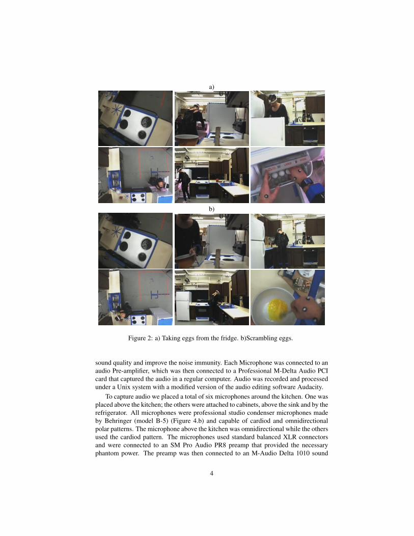
Figure 2 shows several images from the five static cameras and the wearable camera(lower right image) during the process of making scrambled eggs.
2.1.2 Wearable camera
A Firewire camera, FL2-08S2C (640 × 480 pixels), is attached to a head lamp whosebulb has been removed and that is placed around the head of the subject (see Figure1). We recorded the uncompressed video coming from the wearable camera with aDell-620 laptop using the APIs provided by the software Labview. Additionally, thetime stamp of each individual frame is recorded. This laptop also recorded the datacoming from the accelerometers/gyroscopes. Labview allows synchronization of thevideo with the accelerometers/gyroscopes and also provides libraries and support forthe accelerometers. A user Labview interface has been designed (see Figure 3) tocontrol the different configuration parameters of the sensors, including the number ofsensors, their sample rate, or the resolution of the wearable camera.
2.2 Multi channel audioThe audio modality was captured using five Behringer condenser B-5 Microphones (seeFigure 4.b). These high quality Microphones offer different pickup patterns (cardioidor omnidirectional) in order to capture a specific source of sound or a general sample ofthe room. The microphones use balanced 3-pin XLR connectors, which provide better
3
a)
b)
Figure 2: a) Taking eggs from the fridge. b)Scrambling eggs.
sound quality and improve the noise immunity. Each Microphone was connected to anaudio Pre-amplifier, which was then connected to a Professional M-Delta Audio PCIcard that captured the audio in a regular computer. Audio was recorded and processedunder a Unix system with a modified version of the audio editing software Audacity.
To capture audio we placed a total of six microphones around the kitchen. One wasplaced above the kitchen; the others were attached to cabinets, above the sink and by therefrigerator. All microphones were professional studio condenser microphones madeby Behringer (model B-5) (Figure 4.b) and capable of cardiod and omnidirectionalpolar patterns. The microphone above the kitchen was omnidirectional while the othersused the cardiod pattern. The microphones used standard balanced XLR connectorsand were connected to an SM Pro Audio PR8 preamp that provided the necessaryphantom power. The preamp was then connected to an M-Audio Delta 1010 sound
4

Figure 3: Screenshot of LabView software to gather video and accelerome-ters/gyroscopes.
card in an ancient Dell computer running Linux. The Delta 1010 has a breakout box toallow for the connections—two 1/4-inch TRS connections per channel for a balancedsignal.
Audio was recorded using a modified version of Audacity (audacity.sourceforge.net),an open-source audio editor and recorder. Our modifications enabled logging therecording start and stop events so that we could synchronize the audio with the otherrecording modalities.
2.3 Accelerometers and gyroscopesOur third modality is captured with MicroStrain’s 3DM-GX1 inertial measurementunits. These units contain an accelerometer, gyroscope, and magnetometer. They com-bine these signals to measure absolute orientation, as well as angular velocity and in-stantaneous acceleration. All signals are gyro-stabilized and recorded at a regular rate(roughly 60 Hz). The data is captured using LabView software running on the laptopcomputer carried by the subject. Five sensors are placed on the subjects back, legs, andarms. After synchronous activation of all devices, the program cycles through each ofthe five sensors to capture a portion of their data stream. Each sensor is set to transmit acontinuous data stream. The stream then is broken down into packets and immediatelyconverted to calibrated value. The calibrated values are then combined with the sensorserial and the time stamp to be recorded in a text file. Wires provide battery power tothe units and transmit the signal to a serial connector, which is subsequently connectedto a serial-to-usb converter that is connected to the usb port of the laptop.
Each sample from the accelerometer includes several data fields. The “Serial num”
5

Figure 4: a) Point Grey camera b) Microphones. c) Accelerometers/gyrocopes
field contains the serial number of the accelerometer. The “StabMagField” fields con-tain the gyro-stabilized output of the magnetometer. The “StabAccel” fields containthe gyro-stabilized output of the accelerometer. The “StabAngRate” contain the gyro-stabilized angular velocity of the unit. The “StabQ” fields contain a gyro-stabilizedestimate of absolute orientation given as a quaternion. “Ticks” contains the number ofinternal clock ticks since the unit was turned on.“TimeStamp” contains an estimatedtime of the sample from the Windows operating system. Figure 4.c shows an exampleof the accelerometers/gyroscopes used.
2.4 Motion Capture
Our subjects’ whole body and hand motions were recorded in most of the captures.Current state-of-the-art for whole body capture uses a set of 40-60 markers to approx-imate the rigid body motion of 15-22 segments. To the extent possible, the markersare placed on joint axes and bony landmarks so that they can more easily be used tofind the motion of an idealized skeleton. The hands are often modeled as a single rigidlink. We used biomechanical invariants to reduce the number of markers to less thanthe number required to fully specify the orientation of each rigid body segment. Thesystem used was a Vicon motion capture setup with twelve MX-40 cameras for thecaptures. The standard motion capture setup was refined to have additional markers asshown in Figure 5. This marker set captured the motion of the shoulders and back moreaccurately. A whole body motion capture session consists of placing the markers onthe subject in the configuration shown in Figure 5. Then, the subject is asked to brieflyhold a T-pose (arms straight out to the sides), a motorcycle pose (all joints slightly bentas if riding a motorcycle), and a range of motion where the subject moves each jointthrough its full range of motion. This information is used to automatically compute askeleton with limb lengths appropriate for the individual subject in the Vicon software,IQ. Because of the quantity of the data that we intend to capture, the vast majorityof the data clean-up will need to be performed automatically. The IQ software pro-vided by Vicon is capable of automatic clean-up of whole body motion when markersare visible in a number of cameras. For more information on the mocap system seehttp : //mocap.cs.cmu.edu/faqs.php.
6
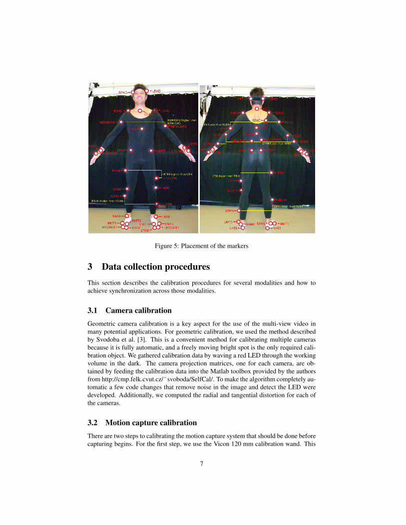
Figure 5: Placement of the markers
3 Data collection proceduresThis section describes the calibration procedures for several modalities and how toachieve synchronization across those modalities.
3.1 Camera calibrationGeometric camera calibration is a key aspect for the use of the multi-view video inmany potential applications. For geometric calibration, we used the method describedby Svodoba et al. [3]. This is a convenient method for calibrating multiple camerasbecause it is fully automatic, and a freely moving bright spot is the only required cali-bration object. We gathered calibration data by waving a red LED through the workingvolume in the dark. The camera projection matrices, one for each camera, are ob-tained by feeding the calibration data into the Matlab toolbox provided by the authorsfrom http://cmp.felk.cvut.cz/˜svoboda/SelfCal/. To make the algorithm completely au-tomatic a few code changes that remove noise in the image and detect the LED weredeveloped. Additionally, we computed the radial and tangential distortion for each ofthe cameras.
3.2 Motion capture calibrationThere are two steps to calibrating the motion capture system that should be done beforecapturing begins. For the first step, we use the Vicon 120 mm calibration wand. This
7

wand has three reflective markers on it. We wave the calibration wand around thevolume of the capture space. When this is completed, the Vicon software runs analgorithm which figures out where each camera is in relation to the other cameras fromthe calibration data. The next step is to set the origin of the capture space by placingthe Vicon L frame in the space we want to designate as the origin within the capturespace.
3.3 Inter-modality synchronizationSynchronization among all the modalities is achieved by combining two different pro-tocols, MultiSync software and Network Time Protocol (NTP). MultiSync softwareis designed to synchronize the image acquisition of multiple compatible Point Greycameras across different IEEE-1394b buses on the same computer and across separatebuses on multiple computers. Moreover, MultiSinc records the system timestamp inorder to be able to synchronize the cameras with other devices. NTP is a protocol forsynchronizing the clocks of computer systems over packet-switched, variable-latencydata networks. NTP uses UDP port 123 as its transport layer. It is designed partic-ularly to resist the effects of variable latency (jitter). NTP is used to synchronize thetime of a computer client or server to another server or reference time source. Thisprotocol is needed in order to synchronize the static cameras, audio, mocap, as well asthe wearable computer and sensors (on-board camera and accelerometers/gyroscope).This technique achieves accuracy typically within a millisecond range. NTP is a mul-tiplatform protocol that works with either Windows and Unix/Linux systems, allowingthe Audio machine (Linux) to be synchronized with the other machines (Windows).NTP fixes a common time in the system using the LAN connection to refine the driftbetween machines. After synchronizing the same time reference in all recording ma-chines, the different modalities are captured at the different sample rate typical of eachmodality. Although the sample rates differ among modalities (30 or 60 samples in thecameras, 100 hertz in the accelerometers or 44100 hertz in the audio), and the samplemoment is different in each modality, utilizing the synchronized reference time assuresa maximum synchronization drift among modalities of half of the slower sample ratemodality. In other words, the maximum drift that will occur among modalities is nomore than 1/30*2 (half 30fps frame) or 0.017 seconds.
4 Database organizationWe have collected five subjects cooking five recipes (average time 15 minutes/recipe).The file organization of the database is illustrated in Figure 6. There are two main filesin the root directory:
• SubjectXX/: Contains the data for subjectXX.
• Util/: Contains software applications to visualize the data (e.g. video codecs,Matlab files to play videos).
Each folder SubjectXX contains subdirectories with the multimodal data:
8

Figure 6: Organization of the database.
• Accelerometers/Gyroscopes:
All accelerometers/Gyroscope data is contained in the SubjectXX/ RecipeNameX/ ac-celerometers directory, in a file named SensorRate.txt . See description of section3.3.
• Audio:
There are six 44.1KHz, 32-bit float wav files for the static microphones and onemp3 for the watch microphone. We also include the original audacity projectfiles which contain the raw data captured by Audacity. Finally, the file “record-ing.log” specifies the starting and ending timestamps logged by our modifiedversion of Audacity when the user pushes “record” and “stop.” These timestampscan be used to synchronize the audio with the other modalities.
• Image data:
All image data is contained in the SubjectXX/RecipeNameX/images directory,organized into separate subdirectories for each camera. The aforementioned sub-directories are named with the word ‘out’ plus the serial number of each camera,except for the onboard camera subdirectory, which is named ‘outOnboard’.
• Motion capture
Motion Capture files are in the SubjectXX/RecipeNameX/mocap directory. Thereare three files per recipe. C3D files contain the markers position for every frame.The Vfile is a file that describes the applicable motion to a skeleton in a varietyof 3D animation software. The Trial file contains the entire capture and has to beopened with the Vicon iQ software.
• Video
Video files are in the SubjectXX/RecipeNameX/video directory. There is oneavi file for each camera named with the same title as the folder that contains the
9

images forming the frames of that video. Moreover, there is a video with the fivemain cameras playing at the same time, and a six view video playing these fivecameras plus the onboard one.
All time stamp information is contained in the SubjectXX/ RecipeNameX/ times-tamps directory. Files STime6510211.txt, STime7101021.txt, STime7150991.txt,STime7151020.txt, STime7151062.txt describe the relationship between the nameof each image and its real time stamp. Otherwise, STimeOnboard.txt only con-tains the sequence of time stamps since file name of the images contains the timestamp of each image.
• Info.xls: Contains a list of all subject files and their size.
10

AcknowledgementsThis work was partially supported by the National Science Foundation under Grant
No. EEEC-0540865. Any opinions, findings, and conclusions or recommendationsexpressed in this material are those of the author(s) and do not necessarily reflect theviews of the National Science Foundation. Thanks to Minh Hoai and Joan Perez forhelping with the camera calibration software. Thanks to Tomas Maldonado for pro-viding the LabView software to record wearable sensors and camera. Thanks to JoanPerez, Ricardo Cervera and Francisco Perez for volunteering to be captured and makingsuch good brownies!
References[1] Carnegie Mellon Motion Capture Database. http://mocap.cs.cmu.edu.[2] C. Schuldt, I. Laptev, and B. Caputo. Recognizing human actions: A local svm
approach. In International Conference on Pattern Recognition (ICPR), 2004.[3] T. Svoboda, D. Martinec, and T. Pajdla. A convenient multi-camera self-calibration
for virtual environments. PRESENCE: Teleoperators and Virtual Environments,14(4):407–422, 2005.
11