guide to welding hot dip galvanized steel v1
TRANSCRIPT

Best Practice Guide for Welding Hot Dip Galvanized SteelsEdition 1.1 | November 2019
www.gaa.com.au

Galvanizers Association of Australia | B
Edition 1.1 | November 2019Best Practice Guide for Welding Hot Dip Galvanized Steel
Introduction 1
Welding Fumes 1
Best practice welding of uncoated steel 1
Appearance of the welded area 1
Chemistry of the welding rod 1
Managing weld splatter 2
Removing welding slag 2
Welding overlapped surfaces 3
Welding to minimise distortion in the
galvanizing process 3
Appearance of the welded area after
galvanizing 4
Weeping welds 4
Rust bleeding 4
Welding galvanized steel 5
GMA welding galvanized steel 5
The GMA welding process 5
Shielding gas for GMA welding
galvanized steel 6
Welding conditions 6
Effect of welding positions in GMA
welding galvanized steel 6
Appearance of GMA welds in
galvanized steel 6
GMA braze welding 6
Manual metal arc welding galvanized
steel 7
Electrodes for manual metal arc
welding galvanized steel 7
Physical properties of arc welds in
galvanized steel 7
GTA brazing Galvanized steel 7
Oxyacetylene welding galvanized steel 8
Brazing 8
Welding galvanized steel reinforcement 8
Butt splice welds 8
Lap splice welds 8
Properties of sound welds in galvanized
steel 9
General properties 9
Fracture toughness 9
Fatigue strength 9
Properties of welds containing porosity 9
General effects 9
Effect of porosity on fatigue strength 9
Cracking 9
Welding galvanized steel to stainless
steel 10
Field repair of areas welded after
galvanizing 10
Weld area damage 10
Repair methods 10
Surface preparation for all conditions 11
Zinc rich paint repair 11
Industrial finish 11
Decorative finish – all environments 11

Galvanizers Association of Australia | 1
Edition 1.1 | November 2019Best Practice Guide for Welding Hot Dip Galvanized Steel
IntroductionNearly all hot dip galvanized steel fabrications involve welding of the steel elements. Occasionally there are defects related to the welding, either aesthetic or structural. This guide describes the best practice welding of steel that is to be hot dip galvanized, shows some common visual defects in the welded area after galvanizing, and how to successfully weld steel that is already galvanized and repair the damaged areas to restore the corrosion protection.
All structural steel welding should be carried out by qualified professionals to the relevant part of AS/NZS 1554 and be compliant with the requirements of AS/NZS 5131. By following these developed and recommended industry practices, the welded joints and fabricated article will reach the expected quality and durability requirements of the user.
Welding FumesThe carcinogenicity of welding fumes was reassessed by the International Agency for Research on Cancer in 2017 after the assessment of substantial new evidence accumulated from observational and experimental studies. Welding fumes and UV radiation from welding were reclassified as “carcinogenic to humans”. This assessment includes mild steel, stainless steel and, for the absence of doubt, galvanized steel. More information is available in the Technical Guidance Note (TGN-SW01) available from Weld Australia. All welding operations should be designed to follow the Safe Work Australia Model Code of Practice for Welding Processes (May 2018).
Best practice welding of uncoated steel
Appearance of the welded areaAll professional welders strive to avoid weld defects. Some visual defects can cause significant problems in the galvanizing process or afterwards when the article is in use. The well-known welding defects such as slag inclusion, undercut, porosity, incomplete fusion, overlap, underfill, spatter, excessive convexity, excessive weld reinforcement, incomplete penetration, and excessive penetration are all known to lead to defects in the galvanized coating varying from the coating not forming properly in the area of the weld, an unattractive appearance, or even fracturing of the fabrication in the vicinity of the weld.
Weld defects that lead to undercuts, porosity, underfill and incomplete penetration all provide areas in the final fabrication where the galvanized coating may not fully form or moisture can collect after installation of the finished article. It is these areas that can lead to earlier corrosion of the steel and a reduction in the service life.
Chemistry of the welding rodDue to the silicon content of some welding rods, welded areas may produce localised duller grey coatings or brighter shiny coatings when hot dip galvanized. The galvanized coating over the weld is normally sound and the appearance will have no detrimental effect on the corrosion protection. The development of dull or shiny coatings due to the silicon content of the weld metal cannot be controlled by the galvanizer.
In most case the configuration of the structure means the initial appearance of the weld after hot dip galvanizing is not critical to the overall appearance of the fabrication. However, on flat surfaces or when straight length tubular sections are joined by welding and the weld areas are ground flush prior to galvanizing, heavier grey coatings may still result due to the difference in the weld and base metal composition. Low silicon welding rods can be used to reduce this effect.
Figure 1 Poor welding practice can lead to areas
of uncoated steel and result in surface conditions
that collect moisture and detritus both leading to a
reduced service life
Figure 2 A porous weld has allowed pre-treatment
solutions to become trapped inside, resulting in a
bare spot near the weld
Figure 3 In this case identical lengths of RHS were joined by welding with a different parent metal to the base
steel. The coating thickness has formed differently in the welded area from the base tube

Galvanizers Association of Australia | 2
Edition 1.1 | November 2019Best Practice Guide for Welding Hot Dip Galvanized Steel
Managing weld splatterThe base steel surface cleanliness affects the quality of galvanized surface finish. Weld splatter (and flame cutting splatter) must be removed by the fabricator prior to galvanizing to ensure a quality surface finish is achieved. AS/NZS 5131 requires weld spatter to be removed for CC2, CC3 and CC4 construction categories. Removal is normally achieved by wire brushing, chipping or grinding.
Anti-spatter sprays and compounds should be avoided for steel that is to be hot dip galvanized (or painted) unless you have prior knowledge they can be removed in the normal pre-treatment process, as they can result in bare spots near to otherwise well-formed welds.
Removing welding slagArc welding slags are chemically inert in acid cleaning solutions and must be mechanically removed by the fabricator before articles are delivered to the galvanizer. Chipping, wire brushing, grinding or abrasive blast cleaning are suitable methods for cleaning in and around the welded area. Pay attention to cleaning the area around the join of the parent and weld metal.
Welding electrode manufacturers supply general purpose electrodes coated with fluxes which produce virtually self-detaching slags and their use is recommended.
Good joint design, combined with adequate access, makes it easier to produce sound continuous welds, avoid locked-in slag, and easy slag removal.
Figure 4 Weld spatter inclusions are usually
spherical due to the surface tension of the metal
while molten. They are often highly adherent
and may not affect the corrosion protection, but
are always a problem when the steel is to be
subsequently painted or powder coated
Figure 5 Small weld spatter inclusions can be seen
under the galvanized surface. In this case the end
use wasn’t affected as the weld spatter is strongly
adhered to the steel
Figure 6 In this case an oil-based anti-spatter spray
hasn’t been cleaned off by the fabricator prior
to galvanizing and has created a series of small
bare spots
Figure 7a Welding slag hasn’t been cleaned by the fabricator after welding and has created a bare spot
Figure 7b A quality weld where slag was removed before galvanizing

Galvanizers Association of Australia | 3
Edition 1.1 | November 2019Best Practice Guide for Welding Hot Dip Galvanized Steel
Welding overlapped surfacesWhen fabricating assemblies with overlapped surfaces, it is best practice to use fully sealed welds when the gap between the surfaces is below 2.5 mm. This is due to zinc’s viscosity and its inability to penetrate such gaps. If unsealed after galvanizing, this will lead to ungalvanized surfaces which will corrode and can result in rust bleeding onto the surrounding galvanized surface. A fully sealed area will also require ventilation of the overlapped areas larger than 100 mm x 100 mm to avoid explosions. More information on best practice venting is included in the GAA’s Design Guide.
Welding to minimise distortion in the galvanizing processThe hot dip galvanizing process will not generally cause distortion if design and fabrication principles are correct. When steel fabrications do distort during hot dip galvanizing, the reasons have usually been ‘built-in’ at an earlier stage. Distortion almost always arises from the relief of stresses as the steel is dipped into the molten 450 °C Zinc of the hot dip galvanizing bath. Although such stresses may be inherent in the steel and may vary from batch to batch, they are more commonly caused during fabrication. Distortion may also occur if steels of significantly different thicknesses are joined together in a fabrication. Only very rarely is it caused by handling in the hot dip galvanizing plant.
Welding two pieces of steel together can result in extreme differences in temperatures within small areas of an assembly and hence significant residual stresses.
In addition to following the requirements of AS/NZS 1554, it is recommended that:
• Components of an assembly be pre-formed accurately so that they need not be forced, sprung or restrained during welding.
• Thick sections should be continuously welded.
• Thin sections and sheet fabrications may benefit from intermittent welding, depending on whether or not heat is conducted rapidly away from the weld, although more stress may arise at the starting point of the weld.
• Welded assemblies should be aligned so that the stresses are balanced rather than all pulling in the same direction.
Fabrication stresses can sometimes be eliminated by stress relieving before galvanizing. Early consultation between galvanizer, fabricator and designer is the key to success in avoiding distortion, through the incorporation of good design features.
Appendix A of AS/NZS 2312.2 is recommended as a further reference for specific information regarding good design practice for articles to be hot dip galvanized.
It is sometimes possible to straighten fabrications after hot dip galvanizing if distortion occurs, so long as the distortion has not affected the structural integrity of the fabrication.
Figure 8 Blowout from undersized hole for venting the overlapping area of the plate fully welded to the large
hollow vessel
The hot dip galvanizing process will not generally cause distortion if design and fabrication principles are correct.

Galvanizers Association of Australia | 4
Edition 1.1 | November 2019Best Practice Guide for Welding Hot Dip Galvanized Steel
Appearance of the welded area after galvanizingThe appearance of the welded area after galvanizing reflects the appearance of the weld prior to galvanizing. The higher the quality of the weld, the higher the quality of the galvanizing in that area.
Section 7 of AS/NZS 5131 provides details of various weld quality levels required for structural steel applications. These are related to the importance level of the structure, service category and fabrication category. In general, the quality of the weld required under AS/NZS 5131 will reflect the durability of the hot dip galvanized coating.
Weeping weldsWeeping welds appear as brown or red stains on the surface of welds, which have a lack of zinc coating caused by weld porosity. Weeping welds should not be confused with rust bleeding, where staining is a result of bleeding of used chemicals from under the overlapping sections.
Weeping welds occur when pre-treatment solutions penetrate porous welds, become trapped and evaporate in the molten zinc bath. The molten zinc itself is too viscous to penetrate the small holes, resulting in small uncoated areas in the weld.
When moisture penetrates the porosity over time, the pre-treatment solutions rehydrate and attack the steel, causing corrosion in the weld. The corrosion products can reach the surface of the weld staining the surface. Corrosion occurring in the weld may pose a safety risk, with the reduction in strength over time potentially causing failure of the part.
Weeping welds can be prevented by ensuring the weld meets the requirements of the relevant Part of the AS/NZS 1554 series and is compliant to AS/NZS 5131.
Rust bleedingRust bleeding occurs when acid salts weep from tightly overlapping surfaces. It cannot be completely avoided and should not be cause for rejection, as described in Clause 7, Note 8 of AS/NZS 4680.
The appearance of the article will usually require a cosmetic solution to be applied. The most common method involves cleaning the rust staining from the surface with a commercial oxalic acid followed by thorough rinsing with water or a proprietary descaling solution followed by a thorough rinsing with water. It is important to then seal or fill as much of the weeping area as possible with silicone which seals the gap, preventing rust products from leaking onto the galvanized surface, minimises air and moisture ingress, which reduces potential for ongoing crevice corrosion and provides less space for corrosion to take place.
If these steps are followed the durability of the article is unlikely to be reduced. It is not recommended to use mechanical working methods to remove the stain caused by rust bleeding as it may alter the surface finish in the cleaned area.
Figure 9 While not a welding defect, steels of
different compositions that have been welded
together in the same plane prior to galvanizing
can result in a differing appearance after hot dip
galvanizing
Figure 12 Rust bleeding (staining) from overlapping
sections with less than a 2.5 mm gap between
stitch welds. This can be remedied after galvanizing
through cleaning of the stains and application of a
sealant such as silicone in the affected areas
Figure 10 Another example of steels of widely
different chemical composition causing an initial
appearance issue for the customer. In most cases
this affect is aesthetic and there is usually no
detrimental effect to the durability of the article
Figure 11 A weeping weld causing rust staining
around the weld surface as the corrosion products
reach the surface
Galvanizers Association of Australia | 5
Edition 1.1 | November 2019Best Practice Guide for Welding Hot Dip Galvanized Steel
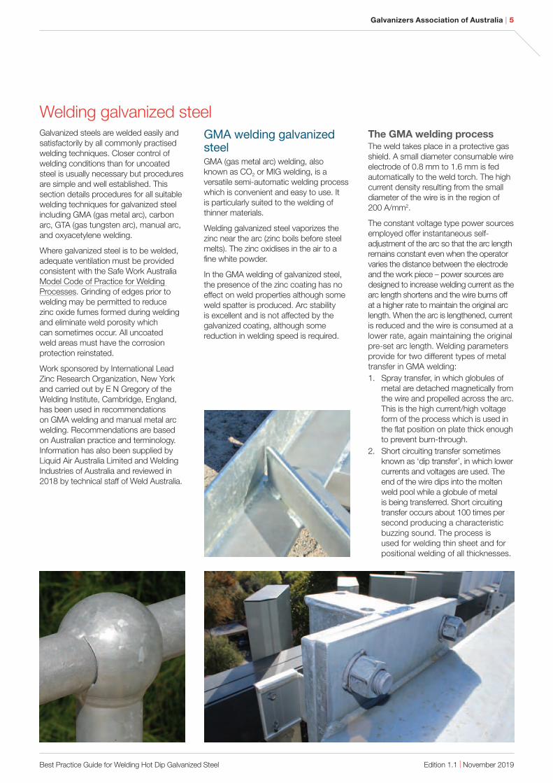
Welding galvanized steelGalvanized steels are welded easily and satisfactorily by all commonly practised welding techniques. Closer control of welding conditions than for uncoated steel is usually necessary but procedures are simple and well established. This section details procedures for all suitable welding techniques for galvanized steel including GMA (gas metal arc), carbon arc, GTA (gas tungsten arc), manual arc, and oxyacetylene welding.
Where galvanized steel is to be welded, adequate ventilation must be provided consistent with the Safe Work Australia Model Code of Practice for Welding Processes. Grinding of edges prior to welding may be permitted to reduce zinc oxide fumes formed during welding and eliminate weld porosity which can sometimes occur. All uncoated weld areas must have the corrosion protection reinstated.
Work sponsored by International Lead Zinc Research Organization, New York and carried out by E N Gregory of the Welding Institute, Cambridge, England, has been used in recommendations on GMA welding and manual metal arc welding. Recommendations are based on Australian practice and terminology. Information has also been supplied by Liquid Air Australia Limited and Welding Industries of Australia and reviewed in 2018 by technical staff of Weld Australia.
GMA welding galvanized steel GMA (gas metal arc) welding, also known as CO2 or MIG welding, is a versatile semi-automatic welding process which is convenient and easy to use. It is particularly suited to the welding of thinner materials.
Welding galvanized steel vaporizes the zinc near the arc (zinc boils before steel melts). The zinc oxidises in the air to a fine white powder.
In the GMA welding of galvanized steel, the presence of the zinc coating has no effect on weld properties although some weld spatter is produced. Arc stability is excellent and is not affected by the galvanized coating, although some reduction in welding speed is required.
The GMA welding process The weld takes place in a protective gas shield. A small diameter consumable wire electrode of 0.8 mm to 1.6 mm is fed automatically to the weld torch. The high current density resulting from the small diameter of the wire is in the region of 200 A/mm2.
The constant voltage type power sources employed offer instantaneous self-adjustment of the arc so that the arc length remains constant even when the operator varies the distance between the electrode and the work piece – power sources are designed to increase welding current as the arc length shortens and the wire burns off at a higher rate to maintain the original arc length. When the arc is lengthened, current is reduced and the wire is consumed at a lower rate, again maintaining the original pre-set arc length. Welding parameters provide for two different types of metal transfer in GMA welding:
1. Spray transfer, in which globules of metal are detached magnetically from the wire and propelled across the arc. This is the high current/high voltage form of the process which is used in the flat position on plate thick enough to prevent burn-through.
2. Short circuiting transfer sometimes known as ‘dip transfer’, in which lower currents and voltages are used. The end of the wire dips into the molten weld pool while a globule of metal is being transferred. Short circuiting transfer occurs about 100 times per second producing a characteristic buzzing sound. The process is used for welding thin sheet and for positional welding of all thicknesses.
Galvanizers Association of Australia | 6
Edition 1.1 | November 2019Best Practice Guide for Welding Hot Dip Galvanized Steel
Shielding gas for GMA
welding galvanized steel Galvanized steel is welded satisfactorily using the GMA process and pure carbon dioxide shielding gas which provides excellent weld penetration, but considerable weld spatter. The use of a spatter release compound may be worthwhile.
Alternatively, the more expensive Ar – CO2 or Ar – CO2 – O2 mixes provide adequate weld penetration, a superior weld bead, and far less spatter. A 92% Ar – 5% CO2 – 3% O2 mixture has been found to provide excellent results on galvanized sheet up to 3.0 mm thickness.
Welding conditionsGMA welding speeds should be lower than on uncoated steel as specified in the weld conditions tables, to allow the galvanized coating to burn off at the front of the weld pool. The reduction in speed is related to the thickness of the coating, the joint type and the welding position, and is generally of the order of 10% to 20%.
Fillet welds in steel with thicker galvanized coatings may be welded more readily if the current is increased by 10 A. The increased heat input helps to burn away the extra zinc at the front of the weld pool.
Penetration of the weld in galvanized steel is less than for uncoated steel so that slightly wider gaps must be provided for butt welds. A slight side to side movement of the welding torch helps to achieve consistent penetration when making butt welds in the flat position.
Effect of welding positions in
GMA welding galvanized steel To achieve complete penetration in the overhead position on sheet with heavy coatings of 85 µm, weld current should be increased by 10 A and voltage by 1V.
Welds in the vertical downwards position may require a speed reduction of 25% to 30% by comparison with uncoated steel, depending on joint type and coating thickness, to prevent rising zinc vapour from interfering with arc stability.
Butt welds in the overhead and horizontal vertical positions require little reduction in speed because the zinc vapour rises away from the weld area.
Appearance of GMA welds in
galvanized steel Surface appearance of GMA welds in galvanized steel is satisfactory although a certain amount of weld spatter is generated, regardless of whether CO2 shielding gas or an Ar – CO2 mixture is used.
Minor coating damage will occur and repairs to the weld area to restore the corrosion protection should be carried out.
Adhesion of weld spatter to the gun nozzle, and to the work piece with resulting marring can be prevented by application before welding of an aerosol spray petroleum base or silicone base spatter release compound available from welding consumables suppliers. Any adhering spatter particles can then easily be brushed off. Silicone-based compounds may interfere with paintability and preparation of the area for painting will be required.
Spatter may also build up in the nozzle of the torch interrupting the flow of shielding gas, in extreme cases causing weld porosity and erratic feeding of filler wire. The application of a spatter release compound to the welding torch nozzle reduces the adherence of spatter particles and with the help of a small wire which can be rubbed inside the nozzle.
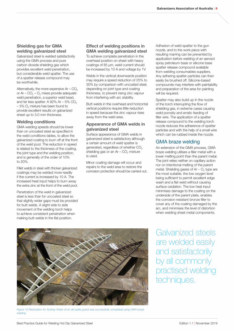
GMA braze welding An extension of the GMA process, GMA braze welding utilises a filler metal with a lower melting point than the parent metal. The joint relies neither on capillary action nor on intentional melting of the parent metal. Shielding gases of Ar – O2 type are the most suitable, the low oxygen level being sufficient to permit excellent edge wash and a flat weld without causing surface oxidation. The low heat input minimises damage to the coating on the underside of the parent plate, enables the corrosion resistant bronze filler to cover any of the coating damaged by the arc, and minimises the level of distortion when welding sheet metal components.
Figure 13 Restoration for Sydney Water of an old spike guard was successfully completed using GMA braze
welding
Galvanized steels are welded easily and satisfactorily by all commonly practised welding techniques.

Galvanizers Association of Australia | 7
Edition 1.1 | November 2019Best Practice Guide for Welding Hot Dip Galvanized Steel
Manual metal arc welding galvanized steel Manual metal arc welding is recommended only for galvanized steel of 1.6 mm thickness or thicker, as difficulty may occur with burning through on light gauges. GMA, GTA, or carbon arc welding are recommended for sheet lighter than 1.6 mm.
In general, manual metal arc welding procedure for galvanized steel sheet is the same as for uncoated steel although the following points should be noted:
1. The welding electrode should be applied a little more slowly than usual with a whipping action which moves the electrode forward along the seam in the direction of progression and then back into the molten pool. All volatilisation of the galvanized coating should be complete before bead progress, after which welding is the same as for uncoated steel.
2. A short arc length is recommended for welding in all positions to give better control of the weld pool and to prevent either intermittent excess penetration or undercutting.
3. Slightly wider gaps up to 2.5 mm are required in butt joints in order to give complete penetration.
4. Grinding of edges prior to welding will satisfactorily reduce fuming from the galvanized coating. Welding schedules will then be the same for uncoated steel.
5. To restore the corrosion protection repairs to the coating must be carried out.
Electrodes for manual metal
arc welding galvanized steelIn general, electrodes to Australian Standard AS/NZS 4855 (ISO 2560) classifications E4312 and E4313 are recommended as suitable for all positions. In butt and tee-joint welds in the flat and horizontal-vertical positions the E4918 basic coated electrode is highly suitable, giving fast, easy welding, improved bead shape, and easier slag removal.
With metal recovery rates of between 110% and 130%, both rutile and basic coated iron powder electrodes perform satisfactorily on galvanized steel, giving a good weld profile with freedom from undercutting, and easy slag removal.
In butt joints in plate with vee edge preparation, an electrode should be chosen which limits the tendency to produce a peaky or convex deposit run since this can cause slag entrapment which will not be removed by subsequent weld runs.
Undercutting in fillet welds is reduced if rutile coated electrodes with a less fluid slag are used since these produce a concave weld profile. Electrodes with very fluid slags tend to produce concave weld profiles with more prevalent undercutting, which is difficult for the welder to rectify.
Different brands of electrodes complying with the same specification may behave differently when used in welding galvanized steel and it may be advisable to carry out simple procedure tests before commencing production welding.
Physical properties of arc
welds in galvanized steelExtensive tensile, bend, radiographic and fatigue testing at the Welding Institute, Cambridge, Engalnd for International Lead Zinc Research Organisation has shown the properties of sound GMA welds and manual metal arc welds in galvanized steel to be equivalent to those of sound welds in uncoated steel. Test welds were made without removing the galvanized coating from edges to be welded.
The presence of any weld porosity due to volatilisation of the galvanized coating during welding has no effect on joint properties except in loss of fatigue strength which can be avoided.
GTA brazing Galvanized steel GTA (gas tungsten arc) process, also known as argon arc, provides an excellent heat source for braze welding.
In GTA brazing, the weld area is shielded from the atmosphere by a protective flow of inert argon gas. A non-consumable tungsten electrode is employed with a separate ‘Cusilman’ (96% Cu, 3% Si, 1% Mn) filler wire, as used for carbon arc welding. The argon barrier prevents oxidation of the electrode or the weld pool and welds of excellent appearance result. The process allows continuous welding at very high speeds, particularly with mechanised arrangements.
In the GTA brazing of galvanized steel the arc should be played on the filler wire rather than on the weld area to prevent undue coating damage.
The following variations in welding technique are also recommended to minimise contamination of the tungsten electrode by traces of zinc oxide fume:
1. Hold the weld torch at a 70° angle rather than the 80° angle normally used for uncoated steel.
2. Increase shielding gas flow from 6 to 12 l/min to flush zinc oxide fume from the electrode area.

Galvanizers Association of Australia | 8
Edition 1.1 | November 2019Best Practice Guide for Welding Hot Dip Galvanized Steel
Corrosion resistance of GTA brazed joints made in galvanized steel is excellent. During the welding operation the corrosion resistant brazed metal tends to wet and flow out over the small area from which the galvanized coating has been volatilised, so ‘healing’ the coating.
GTA welding is recommended only as a heat source for brazing galvanized steel, not as a fusion welding technique. When used for fusion welding the tungsten electrode is fouled rapidly by zinc oxide fume.
Oxyacetylene welding galvanized steel Oxyacetylene welding galvanized steel sheet either with or without a filler rod is generally carried out on the lighter gauges. Because zinc volatilises at about 900 °C while steel melts at about 1500 °C, the necessary welding temperature usually results in coating damage and the need for subsequent treatment of damage areas.
Brazing Coating damage may be overcome by adopting brazing techniques. Brazing employs much lower temperatures (900 °C), producing very little coating damage in the area adjacent to the weld. The weld metal itself is corrosion resistant and tends to wet and cover all bare steel in the weld area so that joints are normally acceptable without further treatment.
The suggested filler rod is a copper-zinc-silicon alloy, such as Austral Tobin Bronze (63% Cu, 37% Zn, 0.3% Si, 0.15% Sn). Prior to brazing, the edges of components should be painted for about 6 mm back with a flux such as Comweld Copper and Brass Flux or Liquid Air 130 Flux.
The lowest practical heat input is desirable and flame adjustment must be oxidising, as this helps to reduce local loss of zinc in the weld zone. Butt welds are preferred to lap joints and the gap in such welds should be equal to half the thickness of the sheet.
Welding galvanized steel reinforcementIn order to volatilise the zinc coating and so achieve adequate weld penetration, both tack welds and load-bearing welds in galvanized steel reinforcement require greater heat input than similar welds in uncoated steel reinforcement. Manual metal arc, GMA and torch welding processes are all suitable techniques, as detailed in AS/NZS 1554 Part 3. In the case of GMA welding, the use of pure CO2 shielding gas will help weld penetration.
Butt splice weldsIn general, welds are made without changes to standard operating parameters other than reduced welding speed to achieve greater heat input. To achieve sound welds, all cracked or damaged areas on bar ends must be removed by sawing or grinding. To provide access for welding at least one bar end must be bevelled.
Lap splice weldsWelds are made satisfactorily using the welding processes listed above. A reduction in welding speed and an increase in heat input will help to volatilise the zinc coating and achieve adequate weld penetration.
For manual metal arc welding, the use of electrodes of a size and type which facilitate volatilisation of the zinc coating will minimise the possibility of weld porosity and liquid metal embrittlement. Cellulose-coated electrodes have given good results. Procedure testing may be helpful.
Alternatively, the galvanized coating may be removed prior to welding by using an oxy-fuel gas flame, or by grit blasting or grinding.

Galvanizers Association of Australia | 9
Edition 1.1 | November 2019Best Practice Guide for Welding Hot Dip Galvanized Steel
Properties of sound welds in galvanized steel
General propertiesWhen welding conditions are chosen to give sound welds in galvanized steel, the tensile, bend and Charpy impact properties are equivalent to those of welds in uncoated steel. Tests showed that the presence of zinc at the levels occurring in the weld metal does not affect tensile, bend or impact properties.
Fracture toughness Crack opening displacement (COD) measurements and drop weight tests established that fracture toughness properties of welds are unaffected by the presence of galvanized coatings.
Fatigue strength The fatigue strength of arc welds in galvanized steel is equivalent to welds in uncoated steel (Figure 14). Fatigue tests were carried out on fillet welded cruciform joints made by CO2 GMA welding with low silicon filler metal of the AWS Classification AWS A5.18:ER70S-2.
CO2 short circuiting GMA welds on 13 mm uncoated and galvanized Lloyds Grade A steel, AWS A5.18:ER70S-2 filler metal. (ref: EN Gregory, ‘The mechanical properties of welds in zinc coated steel’.)
Properties of welds containing porosity
General effects Porosity will occur in certain joint designs in galvanized steel, depending on coating thickness, due to volatilisation of the zinc coating and entrapment of gas in the weld.
The type of joint affects pore formation since gases cannot readily escape from tee joints and lap joints or from butt joints in thick materials. In the case of butt joints, a vee edge preparation or provision of a gap between square edges facilitates the escape of gases, minimising porosity.
Pore formation is also influenced by the thickness of the galvanized coating relative to the steel base. Close attention to welding conditions will reduce the extent of porosity but complete elimination is not always possible, and it is important to consider the effect of porosity on static strength, fatigue strength and cracking of the weld joint.
Effect of porosity on fatigue strength When joints are subject to fatigue loading, welds in galvanized steel should be made oversize to reduce the influence of any porosity in the weld metal.
When a fillet weld in galvanized steel is large enough relative to plate thickness to fail by fatigue from the toe of the weld in the same manner as in uncoated steel, the presence of porosity in the weld does not reduce the fatigue strength of the joint.
Where the dimensions of a weld are just large enough to cause fatigue failure from the toe in a sound weld, a weld containing porosity at the root may fail preferentially through the throat of the weld.
Cracking Intergranular cracking of fillet welds containing porosity, sometimes referred to as zinc penetrator cracking, does not significantly affect the strength of non-critical joints. For more critical stressed applications, however, it is advisable to carry out procedural tests on material and samples.
Str
ess
, M
Pa
Endurance, cycles
61.8
77.1
92.6
108.1
123.5
139.1
154.4
2 3 4 5 2 3 4 5 2 3 4 5104 105 106
Uncoated plate
Galvanized plate
Figure 14 SN curves showing results of fatigue tests on cruciform joints
Porosity will occur in certain joint designs in galvanized steel, depending on coating thickness.

Galvanizers Association of Australia | 10
Edition 1.1 | November 2019Best Practice Guide for Welding Hot Dip Galvanized Steel
Welding galvanized steel to stainless steelWhen hot dip galvanized steel and stainless steel are welded together, the zinc becomes molten and can penetrate the grain boundaries of the stainless steel resulting in a phenomenon called liquid metal cracking (LMC). All types of zinc coatings including zinc rich paint, can cause LMC when they are heated until molten in the presence of stainless steel.
Removing the zinc from the area to be welded prior to welding will eliminate this problem. The most commonly used method is grinding the zinc away from the welded area and thoroughly cleaning the area prior to welding. However, this can still leave small zinc particles around the welded area maintaining the risk of LMC occurring. Another method used to remove the zinc is applying an acid to the surface and then thoroughly rinsing and drying the area prior to welding.
After welding has been completed the damaged areas should be repaired to restore the corrosion protection.
Field repair of areas welded after galvanizingIdeally, the design and build phase of a structure should allow for only the minimum of on-site rectification works. By minimising or eliminating field work, the risk of early corrosion of steelwork is reduced, especially in medium to high corrosivity zones. However, there are times when field welding is a necessary activity and this section provides general information on the repair of hot dip galvanized steel after on-site welding has occurred.
Weld area damageWhen severe damage to the galvanized coating has occurred during welding, protection of the steelwork must be restored. The level and extent of the restoration must be more robust and the repair work completed prior to the article being put in service if the steel will be exposed to severe corrosive conditions in service.
The width of the weld damaged zone will depend on heat input during welding, being greater with a slow process such as oxyacetylene welding than with high speed arc welding. In the manual metal arc welding and oxyacetylene welding of galvanized steel, the weld metal itself will corrode in most atmospheres and the application of a protective coating is essential. Suitable materials for coating the weld metal and adjacent damaged areas of the coating are zinc rich paints, and in some circumstances, zinc metal spraying.
Repair methodsIn the case of weld repairs, additional surface preparation of the damaged area is usually required to remove any welding slag followed by additional abrasive cleaning of the damaged area.
Appropriate coating repair methods in accordance with AS/NZS 4680 are required to achieve at least 100 µm
coating thickness in the repaired area. The Standard provides four options.
1. Organic zinc rich epoxy paint complying with AS/NZS 3750.9. This is normally applied to the repair areas in two coats.
2. Inorganic zinc silicate paint complying with AS/NZS 3750.15 and can be normally applied as a single coat.
3. Zinc metal spray to ISO 2063.
4. Zinc alloy solder stick.
The repair of field damage is often of a lower standard than shop coating due to imperfect surface preparation and difficulty accessing some damaged areas. For this reason, we recommend the coating thickness of the repair in the field to be thicker than repairs carried out in the galvanizing plant or in the fabricator’s manufacturing facility.
After welding has been completed the damaged areas should be repaired to restore the corrosion protection.

Galvanizers Association of Australia | 11
Edition 1.1 | November 2019Best Practice Guide for Welding Hot Dip Galvanized Steel
For field repair of areas damaged after hot dip galvanizing, the GAA recommend the use of organic zinc rich epoxy paint. Further information on the surface preparation and appropriate finishes for different service requirements are detailed below.
It is important to observe normal good painting practice with respect to weather and application conditions. Apply all paint strictly in accordance with paint manufacturers’ recommendations.
Repaired areas of hot dip galvanized steel are normally considered to be most ‘at risk’ of early corrosion. Repaired areas should therefore receive an earlier maintenance inspection than the remainder of the structure.
Surface preparation for all conditions1. Degrease and remove all surface
contaminants
2. Remove all welding scale, slag, rough edges and corrosion products
3. Clean to:
a. AS 1627.2 St 31 (recommended minimum for low to moderate corrosivity zones), or
b. AS 1627.4 Sa 2½ with a surface profile2 (recommended minimum for coastal, marine corrosivity zones).
Zinc rich paint repair
Industrial finishC1 – C3 (low to moderate)
atmospheric corrosivity zones
Apply 2 coats of Galvanite® epoxy zinc rich primer or equivalent to 125 µm – 150 µm DFT.
C4 – C5 (coastal, marine)
atmospheric corrosivity zones
Apply 2 coats of 2 pack epoxy zinc to AS 3750.9 to 150 µm minimum DFT followed by 2 pack epoxy enamel to 150 µm DFT.
Decorative finish – all
environments1. Apply appropriate repair from the
options above, stippling edges of the painted area to achieve optimum appearance of the repair.
2. Where the unrepaired galvanizing has a ‘shiny silver’ appearance and if a very close initial colour match is essential, apply 1 coat of a ‘silver’ paint with an aluminium pigment3 over the zinc rich primer for appearance only. Otherwise a more uniform metallic colour match will be achieved over time4.
Figure 15 Badly repaired field welds which are corroding long before the rest of the fabrication
1 Suitable power tools include power wire brush,
needle gun, disc sander, angle grinder and/or
chipping hammer.2 The Bristle Blaster can achieve a Sa 2½ level
of cleanliness along with a profile for improved
coating adhesion.
The higher the quality of the weld, the higher the appearance quality of the galvanizing in that area.
3 An aluminium (oxide) platelet or leafing aluminium
pigment, which orientate parallel to the substrate
and reflect light, giving the coating a shiny
appearance. 4 Over time, the galvanized coating weathers to
a dull grey and the zinc rich paint will weather
similarly. The ‘silver’ paint will stay shiny and the
repaired area will stand out beside the weathered
dull grey coating.
Galvanizers Association of Australia | 12
Edition 1.1 | November 2019Best Practice Guide for Welding Hot Dip Galvanized Steel
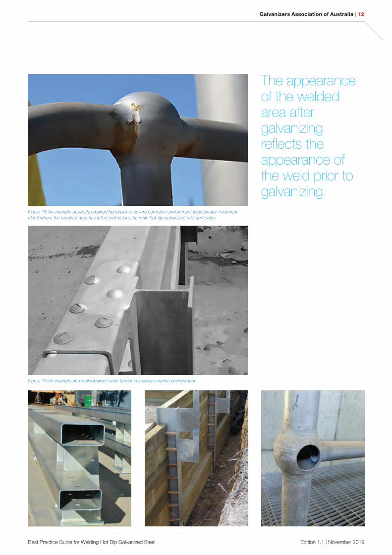
Figure 16 An example of a well repaired crash barrier in a severe marine environment
Figure 15 An example of poorly repaired handrail in a severe corrosive environment (wastewater treatment
plant) where the repaired area has failed well before the main hot dip galvanized rails and posts
The appearance of the welded area after galvanizing reflects the appearance of the weld prior to galvanizing.

We provide information, publications and assistance on all aspects of design, performance and applications of hot dip galvanizing.
Level 5 124 Exhibition Street Melbourne VIC 3000
Telephone 03 9654 1266 Email [email protected] Web gaa.com.au