guidelines and protocols for cardiovascular magnetic...
TRANSCRIPT
Fratz et al. Journal of Cardiovascular Magnetic Resonance 2013, 15:51http://jcmr-online.com/content/15/1/51
POSITION STATEMENT Open Access
Guidelines and protocols for cardiovascularmagnetic resonance in children and adults withcongenital heart disease: SCMR expert consensusgroup on congenital heart diseaseSohrab Fratz1*, Taylor Chung2, Gerald F Greil3, Margaret M Samyn4, Andrew M Taylor5,Emanuela R Valsangiacomo Buechel6, Shi-Joon Yoo7 and Andrew J Powell8*
Abstract
Cardiovascular magnetic resonance (CMR) has taken on an increasingly important role in the diagnostic evaluationand pre-procedural planning for patients with congenital heart disease. This article provides guidelines for theperformance of CMR in children and adults with congenital heart disease. The first portion addresses preparationfor the examination and safety issues, the second describes the primary techniques used in an examination, andthe third provides disease-specific protocols. Variations in practice are highlighted and expert consensusrecommendations are provided. Indications and appropriate use criteria for CMR examination are not specificallyaddressed.
Keywords: Cardiovascular magnetic resonance, Congenital heart disease, Heart defects, Imaging protocols,Magnetic resonance imaging
IntroductionOver the past two decades, there has been a marked in-crease in the use of cardiovascular magnetic resonance(CMR) for the anatomical and functional evaluation ofcongenital heart disease (CHD) [1-6]. CMR is rarelyused as the initial or sole diagnostic imaging modality.Rather it complements echocardiography, provides anon-invasive alternative to x-ray angiography, avoids theionizing radiation exposure of computed tomography,and overcomes many of the limitations of these modal-ities. Expert recommendations regarding the indicationsfor CMR in adults with CHD have recently been pub-lished [7] and are underway for children with CHD. Thisdocument focuses on the performance of CMR in chil-dren and adults with CHD. The first portion addresses
* Correspondence: [email protected]; [email protected] of Pediatric Cardiology and Congenital Heart Disease,Deutsches Herzzentrum München (German Heart Center Munich) of theTechnical University Munich, Munich, Germany8Department of Cardiology, Boston Children’s Hospital, and the Departmentof Pediatrics, Harvard Medical School, Boston, MA, USAFull list of author information is available at the end of the article
© 2013 Fratz et al.; licensee BioMed Central LtCommons Attribution License (http://creativecreproduction in any medium, provided the or
preparation for the examination and safety issues, thesecond describes the primary techniques or modules ofan examination, and the third provides disease-specificprotocols using these modules. The aim is to provide aneducational resource for those engaged in CMR in thispatient population and to help standardize the approachto such patients. As much as possible we try to supportour recommendations by published evidence. However,where data is lacking, the recommendations representan expert consensus view.
Examination preparation and safetyWhen applicable, parents should be provided with a de-tailed description of the CMR examination and asked todiscuss it with their child in an age-appropriate mannerin advance to increase the likelihood of a successfulstudy. Prior to bringing the patient into the scannerroom, the physician and technologists should review thepatient’s history and safety screening form to identifyimplanted devices which may be hazardous in the CMRenvironment or produce image artifact. For patients whomay have undergone a cardiac procedure and have an
d. This is an Open Access article distributed under the terms of the Creativeommons.org/licenses/by/2.0), which permits unrestricted use, distribution, andiginal work is properly cited.

Fratz et al. Journal of Cardiovascular Magnetic Resonance 2013, 15:51 Page 2 of 26http://jcmr-online.com/content/15/1/51
incomplete or unreliable history, a chest radiographshould be obtained to assist screening. A detailed discus-sion on CMR safety and device interactions can befound elsewhere [8-10].Following safety screening, physiological monitoring de-
vices and hearing protection (for both awake and sedatedpatients) are put in place. Young children dissipate bodyheat faster than adults; thus, patient temperature should bemonitored and blankets applied as needed to minimize heatloss. A high-quality electrocardiogram (ECG) signal is es-sential for optimum data quality in cardiac-gated se-quences. The adequacy of the signal should be checked notonly at the onset when the patient is outside the scannerbore, but also once inside it and during actual scanning. Inpatients with dextrocardia, ECG leads are best placed onthe right chest.The imaging coil should be chosen to maximize the
signal-to-noise ratio over the body region to be exam-ined. Because CHD often involves abnormalities of thethoracic vasculature, the coil will usually need to belarge enough to cover the entire thorax and upper abdo-men rather than just the heart. In smaller patients,pediatric thoracic coils or coils designed for an adult-sized head, shoulder, or knee may be suitable. Adequatecoil coverage and placement should be confirmed earlyin the examination by reviewing the localizing images.
SedationPatients undergoing CMR must remain still in the scannerfor up to 60 minutes to minimize motion artifact duringimage acquisition and allow planning of successive imagingsequences. Young children (typically less than age 6 to8 years) and cognitively impaired older patients typically re-quire some form of sedation. Multiple factors should betaken into account when deciding whether a patient shouldhave an examination with sedation including the length ofthe anticipated examination protocol, developmental ma-turity, the patient’s experience with prior procedures, theparents’ opinion of their child’s capability to cooperate withthe examination, the risks of sedation, and the benefits ofthe diagnostic information.Strategies for sedation and anesthesia during CMR
vary and often depend on institutional preference andavailability of resources such as pediatric anesthesiolo-gists with experience in CHD. Sedation in infants youn-ger than approximately six months can be achieved byallowing them to fall into a natural sleep after a feeding[11,12]. The baby is undressed, prepared with ECG-leadsand an oxygen saturation probe, and fed. As soon as theinfant starts falling asleep, it is swaddled or wrapped inan immobilizer, provided noise protection, and placedon the scanner table. With this “feed, swaddle, andsleep” technique, scanning times of 30–60 minutes canbe achieved. However, this approach does not allow
suspension of respiration to reduce motion artifact. Asthe study can be compromised by early awakening, theimaging protocol should be tailored strictly to thehighest priority clinical questions.Alternatively, deep sedation can be achieved with a
variety of medications (e.g., pentobarbital, propofol, fen-tanyl, midazolam, and inhalational agents). Meticulouscare must be taken to maintain spontaneous breathingunder the supervision of an experienced anesthesiologyteam. The principal drawbacks of this approach are anunprotected airway and reliance on spontaneous respira-tory effort with the associated risks of aspiration, airwayobstruction, and hypoventilation. A laryngeal mask airwaymay be used in conjunction with deep sedation to decreasethe risk of aspiration. From an image quality standpoint, re-spiratory motion artifact may reduce sharpness. However,images acquired from sedated, freely-breathing patients areoften still of diagnostic quality as the breathing patterntends to be particularly consistent and thus quite amenableto commonly available respiratory motion compensationtechniques.Because of these safety and image quality concerns,
some institutions prefer to perform sedation using gen-eral anesthesia with mechanical ventilation and endo-tracheal intubation. This approach consistently achievesadequate sedation, protects the airway, and offers con-trol of ventilation. Respiratory motion artifact can beeliminated by suspending ventilation for brief periods(15–60 seconds) in conjunction with neuromuscularblockade. Compared to deep sedation, general anesthesiatends to require more specialized personnel and greaterequipment resources (e.g., a magnetic resonance (MR)compatible anesthesia machine). Both the deep sedationand general anesthesia strategies for CMR have beenshown to have a good safety profile in this fragile patientpopulation [13-18]. MR compatible equipment shouldbe used to monitor the heart rate, transcutaneous oxy-gen saturation, blood pressure, expired carbon dioxide,and body temperature. An appropriately equipped resus-citation cart and emergency management plan for theMR environment should be in place. To maximize pa-tient safety and examination quality, it is recommendedthat different healthcare providers be responsible forsupervising the imaging and sedation/anesthesia aspectsof the study, and that both communicate closely witheach other.
Gadolinium-based contrast agentsGadolinium-based intravenous MR contrast agents(GBCA) are commonly administered in CHD patientsof all ages for angiography and the assessment of myo-cardial perfusion and viability. These agents are oftenused “off-label” in children as several of them are notapproved by regulatory agencies, such as the United

Figure 1 Spin echo and gradient echo cine. 63-year-old patientwho has undergone surgical repair of coarctation of the aorta. Theimages are oriented parallel to the long-axis of the aortic arch andshown in diastole. A. ECG-triggered fast spin echo sequenceacquired with a double inversion preparation pulse to suppresssignal from flowing blood. Note that the resulting signal from bloodis dark. B. ECG-gated steady-state free precession cine sequence.Note the signal from blood is bright.
Fratz et al. Journal of Cardiovascular Magnetic Resonance 2013, 15:51 Page 3 of 26http://jcmr-online.com/content/15/1/51
States Food and Drug Administration or the EuropeanMedicines Agency, for pediatric-age patients. The inci-dence of adverse events related to GBCA in both adultsand children is very low [14,19-21]. The vast majority ofthese reactions are mild and include coldness, warmth, orpain at the injection site; nausea; vomiting; headache; pares-thesias; dizziness; and itching. Severe, life-threatening ana-phylactoid or nonallergic anaphylactic reactions are quiterare (0.001% to 0.01%) [22]. There is no evidence indicatingnephrotoxicity at approved dosages.GBCA administration to patients with acute renal fail-
ure or severe chronic kidney disease is associated withthe development of nephrogenic systemic fibrosis (NSF),a rare and serious condition that involves fibrosis of pri-marily the skin and subcutaneous tissue but may also in-volve the lungs, esophagus, heart, and skeletal muscles.Patients with an estimated glomerular filtration rate <30ml/min/1.73 m2 are considered at highest risk. Thus, allpatients who are candidates for GBCA administrationshould be screened for renal dysfunction, and, if identi-fied, the most recent institutional or national guidelinesregarding GBCA use should be consulted [22,23]. Thereare only a small number of reported cases of NSF inchildren (fewer than 20 as of 2010), the youngest ofwhich was 8 years of age [24,25], and all had significantrenal dysfunction [22]. No NSF cases have been reportedin preterm or term neonates despite their immature kid-ney function and estimated glomerular filtration rateswhich may be < 30 ml/min/1.73 m2 [25]. Accordingly,caution and a careful assessment of benefits and risk butnot prohibition are advised when administering GBCAto neonates and infants [22,23].
Scanner field strengthMost CMR is performed on 1.5 T or 3 T scanners. Ingeneral, 3 T yields a higher signal-to-noise ratio, andtherefore allows for better spatial resolution, which isparticularly desirable in younger, smaller patients. Thisstronger signal and the inherently longer longitudinalrelaxation time (T1) at 3 T, typically lead to improvedclinical performance of coronary angiography, contrast-enhanced angiography, myocardial tagging, and myocar-dial perfusion imaging sequences. However, MR imagingat 3 T has inherently stronger off-resonance artifacts(B0-field inhomogeneity) and dielectric shading artifacts(B1-field inhomogeneity). These factors translate to sig-nificant dark band artifacts and loss of tissue contrast onsteady-state free precession (SSFP) pulse sequences andsignal loss on spin echo pulse sequences that are unpre-dictable [26]. Strategies to reduce some of these artifactsare currently under evaluation [27]. It is also worth not-ing that implanted metallic devices (e.g., sternal wires,stents, septal occluders, and vascular occlusion coils) arecommonly encountered in CHD patients referred for
CMR [28]. Device-related signal loss artifact from T2*effects is typically more pronounced at higher fieldstrengths. Moreover, CMR compatibility information fordevices is more commonly available at the 1.5 T thanthe 3 T field strength.
Common CMR techniques (modules) in CHDThis section focuses only on established CMR tech-niques which are in routine use throughout the CMRcommunity and are available from all scanner manufac-turers. The authors readily acknowledge that newer ap-plications such as 3D phase-contrast flow measurement,real-time and 3D cine imaging, and blood pool contrastagents can be useful when performing CMR in CHDpatients.
Spin echoSpin echo pulse sequences are typically used in CMR togenerate images in which flowing blood appears darkand more stationary tissues appear as varying shades ofgray or white (Figure 1). The most common variants ofthis technique are fast (turbo) spin echo (commercialnames: TSE, Siemens; FSE, General Electric; TSE,Philips) and single-shot fast (turbo) spin echo (commer-cial names: HASTE, Siemens; SSFSE, General Electric;SSTSE, Philips). Both versions usually employ ECG-triggering to compensate for cardiac motion and prepar-ation pulses to suppress signal from blood and improveimage contrast. Respiratory motion can be addressed bybreath-holding, acquiring multiple signal averages, trig-gering from respiratory bellows, or respiratory-navigatorgating. By utilizing half-Fourier k-space filling, thesingle-shot technique acquires all the data to make animage in one heartbeat and is thus very time efficient.The fast spin echo technique collects data for one image

Fratz et al. Journal of Cardiovascular Magnetic Resonance 2013, 15:51 Page 4 of 26http://jcmr-online.com/content/15/1/51
over multiple heartbeats and thus takes longer than thesingle-shot technique, but it produces higher resolutionimages.In contrast to cine gradient echo techniques, spin echo
images are usually acquired during only one portion ofthe cardiac cycle and do not depict motion; they are thustypically used to provide anatomic information. Theirmain advantage over cine imaging is that they are lesssusceptible to artifacts caused by turbulent flow and me-tallic implants such as sternal wires, septal occluders,stents, and vascular occlusion coils (Figure 2) [28]. Inaddition, a thinner slice thickness (≈2 mm) can beachieved which may be particularly useful in smallerpatients. Fast spin echo sequences can also be modifiedto alter image contrast (e.g., T1- and T2-weighting, andfat suppression) and thereby help characterize tissuecomposition.For smaller patients, the operator should use a smaller
voxel size (adjusting both in-plane resolution and slicethickness) to ensure adequate spatial resolution (Table 1).If needed, the reduction in signal-to-noise ratio thatresults may be offset by employing multiple signalaverages. Data acquisition should be timed to the por-tion of the cardiac cycle in which the heart has the leastmotion (i.e., the rest period) to minimize blurring. Atlower heart rates the rest period is often in mid-diastole;whereas at higher heart rates (> 90-100 bpm) it may beat end-systole. Fast spin echo sequences designed forheart rates seen in adults usually acquire data everyheartbeat or every second heartbeat and thus the repeti-tion time (TR) is equal to 1 R-R or 2 R-R intervals, re-spectively. At higher heart rates, the R-R intervalbecomes shorter and the time between data acquisitionwill decrease resulting in less time for longitudinal signalrecovery and thus lower image quality. For rates greaterthan 100 bpm, it may be helpful to compensate for this
Figure 2 Stainless steel coil artifact. 17-year-old patient with dextrocardundergone a Rastelli operation and catheter implantation of a single stainledraining to the left atrium. ECG-gated steady-state free precession sequencsignal loss in the upper left chest (arrow) resulting from the coil. The area oportion of the left pulmonary artery. (C) shows an ECG-triggered fast spin ediastole with a similar orientation as in (B) With this sequence, the extent oclearly visualized.
effect by acquiring image data every third or fourthheartbeat. Higher heart rates are also accompanied byfaster cardiac motion. With the fast spin echo sequence,the number of echoes during the readout (echo trainlength) can be decreased to reduce the image acquisition(shot) duration and better resolve rapidly moving struc-tures. With some implementations of spin echo imaging,the blood suppression preparation pulse may becomeineffective at faster heart rates and blood will appearbrighter. Finally, the default blood suppression prepar-ation pulse will not be effective following the administra-tion of GBCA; thus, in most protocols evaluatinganatomy, spin echo sequences should be performedprior to contrast agent administration.
Gradient echo cineGradient echo cine pulse sequences generate images inwhich flowing blood appears bright (Figure 1). With theuse of ECG-gating, it produces multiple images acrossthe cardiac cycle that can be displayed in cine loop for-mat to visualize motion, one of its main advantages overspin echo sequences. Respiratory motion artifact can beminimized by breath-holding (preferred when possible)or by acquiring 2–4 signal averages with the patientbreathing. In clinical practice, this imaging sequence isoften prescribed across the anatomy of interest to yield astack of contiguous cross-sectional slices that can bedisplayed in a multi-location, multi-phase format.Gradient echo cine imaging can be performed using a
standard spoiled gradient echo pulse sequence or thesubsequently developed SSFP sequence (commercialnames: TrueFISP, Siemens; FIESTA, General Electric;balanced-FFE, Philips). SSFP imaging is faster and pro-vides superior contrast between blood and myocardiumcompared to standard gradient echo imaging and isthus more commonly used. The SSFP sequence is also
ia, double-outlet right ventricle, and pulmonary stenosis who hasss steel vascular coil to occlude a small left superior vena cavae in a coronal plane (A) and axial plane (B) demonstrating a region off signal loss is several times larger than the coil and obscures acho sequence with a double inversion preparation pulse acquired inf signal loss artifact is reduced, and the left pulmonary artery is more
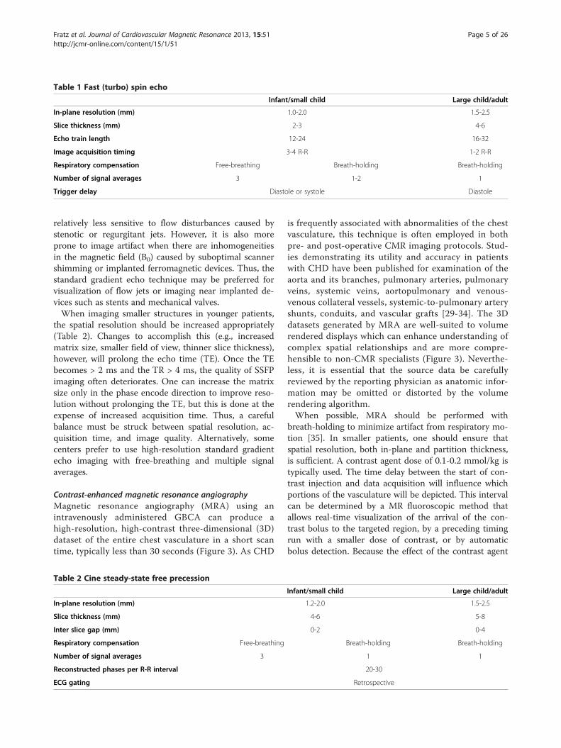
Table 1 Fast (turbo) spin echo
Infant/small child Large child/adult
In-plane resolution (mm) 1.0-2.0 1.5-2.5
Slice thickness (mm) 2-3 4-6
Echo train length 12-24 16-32
Image acquisition timing 3-4 R-R 1-2 R-R
Respiratory compensation Free-breathing Breath-holding Breath-holding
Number of signal averages 3 1-2 1
Trigger delay Diastole or systole Diastole
Fratz et al. Journal of Cardiovascular Magnetic Resonance 2013, 15:51 Page 5 of 26http://jcmr-online.com/content/15/1/51
relatively less sensitive to flow disturbances caused bystenotic or regurgitant jets. However, it is also moreprone to image artifact when there are inhomogeneitiesin the magnetic field (B0) caused by suboptimal scannershimming or implanted ferromagnetic devices. Thus, thestandard gradient echo technique may be preferred forvisualization of flow jets or imaging near implanted de-vices such as stents and mechanical valves.When imaging smaller structures in younger patients,
the spatial resolution should be increased appropriately(Table 2). Changes to accomplish this (e.g., increasedmatrix size, smaller field of view, thinner slice thickness),however, will prolong the echo time (TE). Once the TEbecomes > 2 ms and the TR > 4 ms, the quality of SSFPimaging often deteriorates. One can increase the matrixsize only in the phase encode direction to improve reso-lution without prolonging the TE, but this is done at theexpense of increased acquisition time. Thus, a carefulbalance must be struck between spatial resolution, ac-quisition time, and image quality. Alternatively, somecenters prefer to use high-resolution standard gradientecho imaging with free-breathing and multiple signalaverages.
Contrast-enhanced magnetic resonance angiographyMagnetic resonance angiography (MRA) using anintravenously administered GBCA can produce ahigh-resolution, high-contrast three-dimensional (3D)dataset of the entire chest vasculature in a short scantime, typically less than 30 seconds (Figure 3). As CHD
Table 2 Cine steady-state free precession
In-plane resolution (mm)
Slice thickness (mm)
Inter slice gap (mm)
Respiratory compensation Free-breathing
Number of signal averages 3
Reconstructed phases per R-R interval
ECG gating
is frequently associated with abnormalities of the chestvasculature, this technique is often employed in bothpre- and post-operative CMR imaging protocols. Stud-ies demonstrating its utility and accuracy in patientswith CHD have been published for examination of theaorta and its branches, pulmonary arteries, pulmonaryveins, systemic veins, aortopulmonary and venous-venous collateral vessels, systemic-to-pulmonary arteryshunts, conduits, and vascular grafts [29-34]. The 3Ddatasets generated by MRA are well-suited to volumerendered displays which can enhance understanding ofcomplex spatial relationships and are more compre-hensible to non-CMR specialists (Figure 3). Neverthe-less, it is essential that the source data be carefullyreviewed by the reporting physician as anatomic infor-mation may be omitted or distorted by the volumerendering algorithm.When possible, MRA should be performed with
breath-holding to minimize artifact from respiratory mo-tion [35]. In smaller patients, one should ensure thatspatial resolution, both in-plane and partition thickness,is sufficient. A contrast agent dose of 0.1-0.2 mmol/kg istypically used. The time delay between the start of con-trast injection and data acquisition will influence whichportions of the vasculature will be depicted. This intervalcan be determined by a MR fluoroscopic method thatallows real-time visualization of the arrival of the con-trast bolus to the targeted region, by a preceding timingrun with a smaller dose of contrast, or by automaticbolus detection. Because the effect of the contrast agent
Infant/small child Large child/adult
1.2-2.0 1.5-2.5
4-6 5-8
0-2 0-4
Breath-holding Breath-holding
1 1
20-30
Retrospective

Figure 3 Contrast-enhanced magnetic resonance angiography.9-year-old patient with partially anomalous pulmonary venous returnof the left upper pulmonary vein (arrow) to the leftward aspect ofthe left innominate vein. Contrast-enhanced magnetic resonanceangiogram shown in a coronal plane using a sub-volume maximalintensity projection (A) and volume rendering (B).
Fratz et al. Journal of Cardiovascular Magnetic Resonance 2013, 15:51 Page 6 of 26http://jcmr-online.com/content/15/1/51
persists even during recirculation, two or three sequentialMRA data acquisitions are useful to ensure visualization ofall the vasculature. More recently, imaging accelerationtechniques have been applied to shorten the acquisitiontime to 2–5 seconds thereby permitting multiple 3D vol-ume sets to be acquired as the contrast agent passesthrough the circulation producing a “time-resolved” MRA[36-39]. A smaller contrast dose (0.05-0.1 mmol/kg) is oftenused. This time-resolved approach has several potential ad-vantages: 1) observing the passage of contrast may havediagnostic benefits, 2) timing of the acquisition is less crit-ical because multiple volume sets are obtained as the con-trast passes through the circulation, and 3) it may have lesssensitivity to respiratory motion artifact. The principaldisadvantage with this technique is that the decrease inacquisition time is usually achieved in part from a reduc-tion in spatial resolution which may hinder diagnosticaccuracy, particularly in smaller patients. In addition, theundersampling of k-space used to accelerate the acquisi-tion may result in image artifact.Both the standard and time-resolved contrast MRA
techniques do not utilize ECG-gating; therefore, motionover the cardiac cycle causes blurring, particularly of theaortic root, coronary arteries, and intracardiac struc-tures. Another disadvantage is that the use of GBCA in-curs some risk of adverse reactions (see above).
Table 3 ECG and respiratory navigator-gated 3D steady-state
Inf
Isotropic resolution (mm3)
Navigator window (mm)
Image acquisition duration (ms)
Trigger delay End-sys
ECG and respiratory navigator-gated 3D SSFPIn its typical implementation, the ECG and respiratorynavigator-gated 3D SSFP technique delivers a 3D ana-tomic dataset with an isotropic voxel size of approxi-mately 1.2-2.0 mm without the use of a contrast agent(Table 3). Its utility and validation have been reported inpatients with CHD [40-42]. Using ECG triggering, thedata acquisition is confined to one or two portions ofthe cardiac cycle thereby minimizing blurring from car-diac motion. Intracardiac anatomy and coronary arteriescan thus be more clearly visualized than with contrast-enhanced MRA. The 3D SSFP sequence is performedwith free-breathing. Respiratory motion is compensatedfor by gating data acquisition to expiration with the use ofa navigator beam tracking the motion of the diaphragm.This approach allows for improvement in spatial resolutionincluding isotropic voxel size because scan time is not lim-ited to the duration of a single breath-hold. The isotropicproperty of the anatomic data permits arbitrary reformat-ting in any desired imaging plane during review withoutthe loss of resolution (Figure 4).The 3D SSFP sequence has four principal disadvan-
tages. First, its acquisition time is relatively long, usuallyapproximately 7–10 min, during which the patient mustbe absolutely still. Younger children may have difficultywith this level of cooperation. Second, the sequence isvery susceptible to artifacts caused by turbulent flow andmagnetic field inhomogeneity such as that caused by pres-ence of stents or other ferromagnetic implants. Therefore,vessels with stenosis or regurgitation, and structures aroundstents can sometimes be misinterpreted. Third, the data isconfined to one or two portions of the cardiac cycle therebyprecluding the evaluation of cardiac and vessel motion. Fi-nally, as with other ECG-gated techniques, image qualitywill suffer when the patient has an irregular heart rhythm.In such cases, generating stacks of thin SSFP localizer typeimages in the cardinal planes during a breath-hold orfree-breathing with 2–3 signal averages may be a usefulalternative.A version of 3D SSFP is generally the technique of
choice for coronary artery imaging in patients with CHD(Figure 5) [43-46]. For this purpose in particular, dataacquisition must be confined to the rest period of thecardiac cycle (i.e., that with the least motion) tominimize blurring of these small, fast moving structures.
free precession
ant/small child Large child/adult
1.2-1.5 1.3-2.0
3 5
40-60 80-150
tole or mid-diastole Mid-diastole
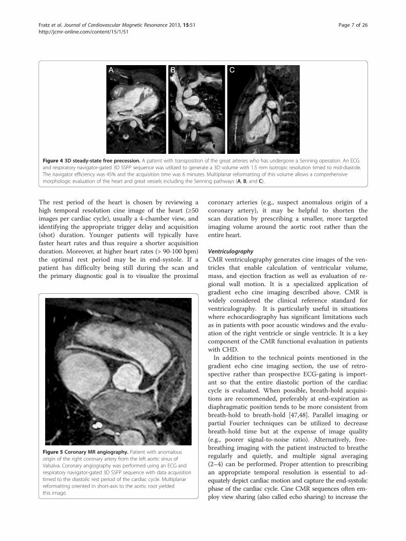
Figure 4 3D steady-state free precession. A patient with transposition of the great arteries who has undergone a Senning operation. An ECGand respiratory navigator-gated 3D SSFP sequence was utilized to generate a 3D volume with 1.5 mm isotropic resolution timed to mid-diastole.The navigator efficiency was 45% and the acquisition time was 6 minutes. Multiplanar reformatting of this volume allows a comprehensivemorphologic evaluation of the heart and great vessels including the Senning pathways (A, B, and C).
Fratz et al. Journal of Cardiovascular Magnetic Resonance 2013, 15:51 Page 7 of 26http://jcmr-online.com/content/15/1/51
The rest period of the heart is chosen by reviewing ahigh temporal resolution cine image of the heart (≥50images per cardiac cycle), usually a 4-chamber view, andidentifying the appropriate trigger delay and acquisition(shot) duration. Younger patients will typically havefaster heart rates and thus require a shorter acquisitionduration. Moreover, at higher heart rates (> 90-100 bpm)the optimal rest period may be in end-systole. If apatient has difficulty being still during the scan andthe primary diagnostic goal is to visualize the proximal
Figure 5 Coronary MR angiography. Patient with anomalousorigin of the right coronary artery from the left aortic sinus ofValsalva. Coronary angiography was performed using an ECG andrespiratory navigator-gated 3D SSFP sequence with data acquisitiontimed to the diastolic rest period of the cardiac cycle. Multiplanarreformatting oriented in short-axis to the aortic root yieldedthis image.
coronary arteries (e.g., suspect anomalous origin of acoronary artery), it may be helpful to shorten thescan duration by prescribing a smaller, more targetedimaging volume around the aortic root rather than theentire heart.
VentriculographyCMR ventriculography generates cine images of the ven-tricles that enable calculation of ventricular volume,mass, and ejection fraction as well as evaluation of re-gional wall motion. It is a specialized application ofgradient echo cine imaging described above. CMR iswidely considered the clinical reference standard forventriculography. It is particularly useful in situationswhere echocardiography has significant limitations suchas in patients with poor acoustic windows and the evalu-ation of the right ventricle or single ventricle. It is a keycomponent of the CMR functional evaluation in patientswith CHD.In addition to the technical points mentioned in the
gradient echo cine imaging section, the use of retro-spective rather than prospective ECG-gating is import-ant so that the entire diastolic portion of the cardiaccycle is evaluated. When possible, breath-hold acquisi-tions are recommended, preferably at end-expiration asdiaphragmatic position tends to be more consistent frombreath-hold to breath-hold [47,48]. Parallel imaging orpartial Fourier techniques can be utilized to decreasebreath-hold time but at the expense of image quality(e.g., poorer signal-to-noise ratio). Alternatively, free-breathing imaging with the patient instructed to breatheregularly and quietly, and multiple signal averaging(2–4) can be performed. Proper attention to prescribingan appropriate temporal resolution is essential to ad-equately depict cardiac motion and capture the end-systolicphase of the cardiac cycle. Cine CMR sequences often em-ploy view sharing (also called echo sharing) to increase the
Fratz et al. Journal of Cardiovascular Magnetic Resonance 2013, 15:51 Page 8 of 26http://jcmr-online.com/content/15/1/51
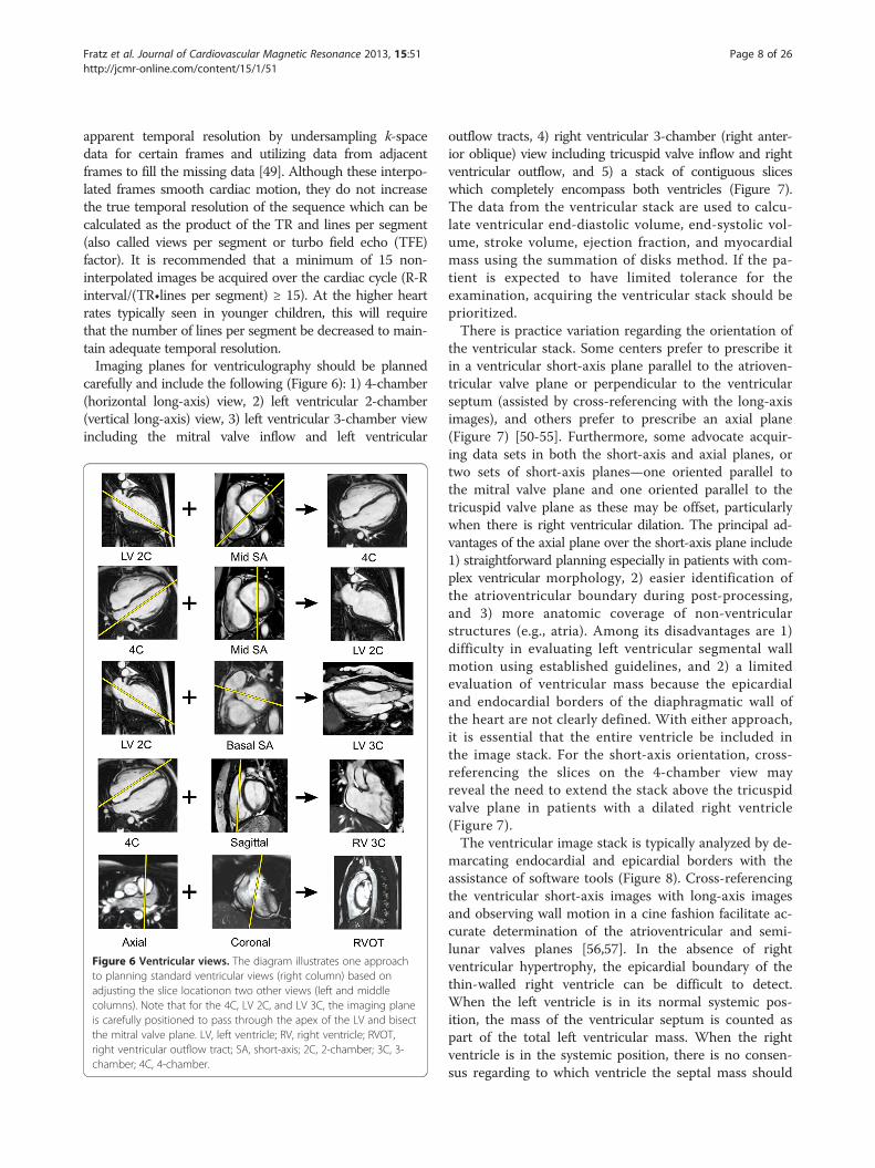
apparent temporal resolution by undersampling k-spacedata for certain frames and utilizing data from adjacentframes to fill the missing data [49]. Although these interpo-lated frames smooth cardiac motion, they do not increasethe true temporal resolution of the sequence which can becalculated as the product of the TR and lines per segment(also called views per segment or turbo field echo (TFE)factor). It is recommended that a minimum of 15 non-interpolated images be acquired over the cardiac cycle (R-Rinterval/(TR•lines per segment) ≥ 15). At the higher heartrates typically seen in younger children, this will requirethat the number of lines per segment be decreased to main-tain adequate temporal resolution.Imaging planes for ventriculography should be planned
carefully and include the following (Figure 6): 1) 4-chamber(horizontal long-axis) view, 2) left ventricular 2-chamber(vertical long-axis) view, 3) left ventricular 3-chamber viewincluding the mitral valve inflow and left ventricular
Figure 6 Ventricular views. The diagram illustrates one approachto planning standard ventricular views (right column) based onadjusting the slice locationon two other views (left and middlecolumns). Note that for the 4C, LV 2C, and LV 3C, the imaging planeis carefully positioned to pass through the apex of the LV and bisectthe mitral valve plane. LV, left ventricle; RV, right ventricle; RVOT,right ventricular outflow tract; SA, short-axis; 2C, 2-chamber; 3C, 3-chamber; 4C, 4-chamber.
outflow tracts, 4) right ventricular 3-chamber (right anter-ior oblique) view including tricuspid valve inflow and rightventricular outflow, and 5) a stack of contiguous sliceswhich completely encompass both ventricles (Figure 7).The data from the ventricular stack are used to calcu-late ventricular end-diastolic volume, end-systolic vol-ume, stroke volume, ejection fraction, and myocardialmass using the summation of disks method. If the pa-tient is expected to have limited tolerance for theexamination, acquiring the ventricular stack should beprioritized.There is practice variation regarding the orientation of
the ventricular stack. Some centers prefer to prescribe itin a ventricular short-axis plane parallel to the atrioven-tricular valve plane or perpendicular to the ventricularseptum (assisted by cross-referencing with the long-axisimages), and others prefer to prescribe an axial plane(Figure 7) [50-55]. Furthermore, some advocate acquir-ing data sets in both the short-axis and axial planes, ortwo sets of short-axis planes—one oriented parallel tothe mitral valve plane and one oriented parallel to thetricuspid valve plane as these may be offset, particularlywhen there is right ventricular dilation. The principal ad-vantages of the axial plane over the short-axis plane include1) straightforward planning especially in patients with com-plex ventricular morphology, 2) easier identification ofthe atrioventricular boundary during post-processing,and 3) more anatomic coverage of non-ventricularstructures (e.g., atria). Among its disadvantages are 1)difficulty in evaluating left ventricular segmental wallmotion using established guidelines, and 2) a limitedevaluation of ventricular mass because the epicardialand endocardial borders of the diaphragmatic wall ofthe heart are not clearly defined. With either approach,it is essential that the entire ventricle be included inthe image stack. For the short-axis orientation, cross-referencing the slices on the 4-chamber view mayreveal the need to extend the stack above the tricuspidvalve plane in patients with a dilated right ventricle(Figure 7).The ventricular image stack is typically analyzed by de-
marcating endocardial and epicardial borders with theassistance of software tools (Figure 8). Cross-referencingthe ventricular short-axis images with long-axis imagesand observing wall motion in a cine fashion facilitate ac-curate determination of the atrioventricular and semi-lunar valves planes [56,57]. In the absence of rightventricular hypertrophy, the epicardial boundary of thethin-walled right ventricle can be difficult to detect.When the left ventricle is in its normal systemic pos-ition, the mass of the ventricular septum is counted aspart of the total left ventricular mass. When the rightventricle is in the systemic position, there is no consen-sus regarding to which ventricle the septal mass should
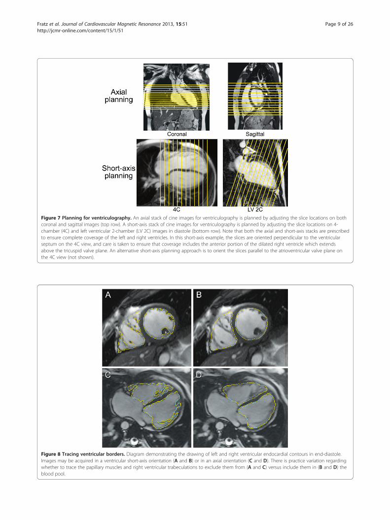
Figure 7 Planning for ventriculography. An axial stack of cine images for ventriculography is planned by adjusting the slice locations on bothcoronal and sagittal images (top row). A short-axis stack of cine images for ventriculography is planned by adjusting the slice locations on 4-chamber (4C) and left ventricular 2-chamber (LV 2C) images in diastole (bottom row). Note that both the axial and short-axis stacks are prescribedto ensure complete coverage of the left and right ventricles. In this short-axis example, the slices are oriented perpendicular to the ventricularseptum on the 4C view, and care is taken to ensure that coverage includes the anterior portion of the dilated right ventricle which extendsabove the tricuspid valve plane. An alternative short-axis planning approach is to orient the slices parallel to the atrioventricular valve plane onthe 4C view (not shown).
Figure 8 Tracing ventricular borders. Diagram demonstrating the drawing of left and right ventricular endocardial contours in end-diastole.Images may be acquired in a ventricular short-axis orientation (A and B) or in an axial orientation (C and D). There is practice variation regardingwhether to trace the papillary muscles and right ventricular trabeculations to exclude them from (A and C) versus include them in (B and D) theblood pool.
Fratz et al. Journal of Cardiovascular Magnetic Resonance 2013, 15:51 Page 9 of 26http://jcmr-online.com/content/15/1/51

Fratz et al. Journal of Cardiovascular Magnetic Resonance 2013, 15:51 Page 10 of 26http://jcmr-online.com/content/15/1/51
be allocated. In patients with ventricular conductiondelay, which is relatively common in CHD, the end-systolic and end-diastolic frames (i.e., time point in thecardiac cycle) may not be the same for the right and leftventricles and should thus be selected independently toyield the minimum and maximum volumes respectively.There is practice variation regarding whether to tracethe papillary muscles and right ventricular trabeculationsin order to exclude them from blood pool and countthem toward ventricular mass (Figure 8) [58-61]. Tra-cing these structures will yield smaller ventricular vol-umes, with little change in stroke volume but a higherejection fraction. Though theoretically more accurate,this approach is time consuming in the absence of a reli-able automated system and may reduce measurementreproducibility.Normative data on ventricular parameters by CMR are
available for both adults and older children [50,52,53,62,63];there is still a need for robust data in patients younger than8 years. Given the practice variations in the methods of ac-quiring and analyzing the ventriculography image datanoted above, it is recommended that a center’s approach tothese issues correspond to that used in the normativedataset that has been selected as the center’s referencevalues. Although indexing ventricular volumes to body sur-face area is a common practice, this does not fully accountfor changes in body size from infancy to adulthood as thevolumes do not vary linearly with body surface area[52,64,65]. Thus, a given indexed volume (e.g., end-diastolicvolume of 80 ml/m2) may be normal for an adult but abovenormal for an infant.One of the strengths of CMR ventriculography is that
studies have demonstrated very good reproducibility inchildren and adults with CHD [58,66-69]. To achievethis level of quality and reliability, centers should main-tain a rigorous and consistent approach to imaging andanalysis. Furthermore, to optimize interstudy reproduci-bility in patients followed longitudinally, the ventricularborders demarcated in the analysis software should besaved so that they can be compared side-by-side withthose from subsequent studies.
Blood velocity and flow measurementVelocity-encoded phase-contrast (PC) cine CMR is theprimary technique used to measure blood flow velocityand volume. A detailed description can be found else-where [70-73]. In brief, PC CMR is based on theprinciple that the signal from hydrogen nuclei (such asthose in blood) flowing through specially designed mag-netic field gradients accumulates a predictable andmeasurable phase shift that is proportional to its vel-ocity. A PC CMR pulse sequence produces two sets ofcine images: magnitude images that provide anatomicinformation and phase images in which the velocity
information is encoded. On the phase images, the signalamplitude (brightness) of each voxel is proportional tomean flow velocity within that voxel. Maximum velocityin one direction is displayed as the brightest white, max-imum velocity in the opposite direction as the darkestblack, and zero velocity as mid-grey. Using specializedsoftware, regions of interest around a vessel are defined,and the flow rate is automatically calculated from theproduct of the mean velocity and the cross-sectionalarea.Blood flow measurements are an important element of
the CMR examination of CHD patients and have variety ofapplications. Examples include measurement of cardiacoutput [74,75], pulmonary-to-systemic flow ratio (Qp/Qs)[76-81], differential lung perfusion [82-85], valvular regurgi-tation [55,86-94], aortopulmonary collateral flow [95-97],and pressure gradient [98-101].For PC CMR flow measurements, the use of retro-
spective rather than prospective ECG-gating is preferredso that the entire diastolic portion of the cardiac cycle isevaluated (Table 4). The quality of the ECG-gatingshould be carefully monitored, particularly during acqui-sitions lasting several minutes. If the heart rate changessignificantly or there are frequent invalid triggers, the se-quence should be stopped and repeated. Measurementscan be performed with free-breathing and multiple sig-nal averages (2–4) or by shortening the scan time so thatit can comfortably be performed within a breath-hold.The reduced scan time is usually achieved by reductionsin temporal and spatial resolution, as well as faster gra-dient switching–all of which may increase measurementerror. Moreover, physiological changes can occur withbreath-holding that alter the measurements [102-104]and may confound clinical interpretation. For these rea-sons, the authors recommend free-breathing acquisi-tions. The scan time of these measurements may bereduced with the use of parallel imaging [80,105,106].Accurate PC CMR measurements require sufficient
spatial resolution to avoid significant partial volumeeffects. Specifically, there should be more than 3 pixelsacross the diameter or more than 8 pixels in the cross-section of the vessel or cardiac valve of interest [107,108].Proper attention to prescribing an appropriate temporalresolution is also essential because under-sampling willsmooth a pulsatile flow curve and cause inaccuracies. ForPC CMR, true temporal resolution (as opposed to interpo-lated temporal resolution) equals 2•TR•lines per segment(lines per segment is also called views per segment or TFEfactor). It is recommended that a minimum of 20 non-interpolated images be acquired over the cardiac cycle (R-Rinterval/(2•TR•lines per segment) ≥ 20). At the higher heartrates typically seen in younger children, this will requirethat the number of lines per segment be decreased to main-tain adequate temporal resolution. Finally, with PC CMR

Table 4 Velocity-encoded phase-contrast cine for quantitative flow measurements
Infant/small child Large child/adult
In-plane resolution (mm) 1.0-1.3 1.3-2.0
Slice thickness (mm) 5 6-8
Number of signal averages 3
Reconstructed phases per R-R interval 25-30
Velocity encoding (cm/s) Artery 200, vein 100, atrioventricular-valve inflow 150
Cardiac/respiratory motion Retrospective ECG-gating with free-breathing
Fratz et al. Journal of Cardiovascular Magnetic Resonance 2013, 15:51 Page 11 of 26http://jcmr-online.com/content/15/1/51
measurements, the operator must set the velocity range(venc) prior to running the pulse sequence; velocities whichexceed this range will alias and be misrepresented (Figure 9).It is recommended that the venc be set to approximately25% above the expected maximum velocity so as tooptimize the dynamic range. When blood velocity is in-creased, such as in the setting of valve or vessel stenosis,the operator’s choice of venc may be guided by informationfrom recent echocardiography. If aliasing occurs, the meas-urement should be repeated using a higher venc or the datamay be rescaled with cautious use of post-processingsoftware.Careful positioning of the PC CMR imaging plane is
essential for accurate velocity and flow measurements. Itshould be aligned strictly perpendicular to the bloodvessel’s or valve’s orientation using two orthogonal plan-ning views in order to minimize partial volume effects
Figure 9 Effect of aliasing on phase-contrast cine CMR (PC CMR) flowtetralogy of Fallot and mild pulmonary valve stenosis. PC CMR was performincorrectly at 200 cm/sec (top row) and then with the venc set correctly atin systole, and the resulting flow curves (C, F) generated from analyzing thvelocity is 260 cm/sec, aliasing (B) and flow underestimation (C) are seen w
(Figure 10), and the velocity encoding direction shouldbe set to the through-plane direction. The vessel ofinterest should be as close to the scanner’s isocenter aspossible to maximize gradient fidelity (Figure 11). This isaccomplished by prescribing the plane so that the centerof the image is at the same level as the vessel in thesuperoinferior direction. The scanner will then slide thepatient table so that the center of the imaging plane andthus the vessel is close to the scanner’s isocenter. Place-ment of the imaging plane in regions of turbulent flowshould be avoided as such flow can lead to signal lossand inaccuracies. Similarly, positioning of the imagingplane away from ferromagnetic implanted devices isrecommended as these disrupt the magnetic fieldgradients.There is some uncertainty and practice variation re-
garding the optimal location for semilunar valve flow
measurements. Sixteen-year-old patient with surgically repaireded in the main pulmonary artery with the velocity range (venc) set300 cm/sec (bottom row). Magnitude (A, D) and phase images (B, E)e region of interest (yellow contour) are shown. Because the peakith a venc of 200 cm/sec but not with a venc of 300 cm/sec (E and F).

Figure 10 Planning a CMR phase-contrast acquisition to measure flow in the main pulmonary artery. The PC CMR imaging plane issimultaneously viewed and adjusted on orthogonal views of the main pulmonary artery (top row) to ensure that it is oriented perpendicular tothe blood vessel. The resulting magnitude and phase images are shown (bottom row).
Figure 11 Proper positioning of the imaging plane for main pulmonary artery blood flow measurement. PC CMR velocity and flowmeasurements are most accurate when the location of interest is at the isocenter of the scanner during the acquisition. Most MR scanners willslide the patient table so that the center of the imaging plane (yellow circle) is at the scanner’s isocenter (vertical red line). Prescribing theimaging plane so that the center of the image is at the same level in the superoinferior dimension as the location of interest istherefore recommended.
Fratz et al. Journal of Cardiovascular Magnetic Resonance 2013, 15:51 Page 12 of 26http://jcmr-online.com/content/15/1/51

Figure 12 First-pass perfusion. Patient with anomalous origin ofthe left coronary artery from the pulmonary artery who underwentleft coronary artery re-implantation and subsequently developedsevere stenosis of the re-implanted coronary artery. First-passperfusion images at a mid-ventricular level with adenosine stress (A)and at rest (B). Note the extensive sub-endocardial hypoperfusion ofthe left ventricle at stress but not at rest which indicatesinducible ischemia.
Fratz et al. Journal of Cardiovascular Magnetic Resonance 2013, 15:51 Page 13 of 26http://jcmr-online.com/content/15/1/51
measurement. A position closer to the annulus has thepotential advantages of a less complex flow pattern,reduced impact of vessel compliance, and exclusion ofcoronary flow in the case of the aortic valve [109].Through-plane motion, however, is greatest near theannulus, and this contributes to measurement error[110,111] and precludes precise placement between theannulus and coronary ostia throughout the cardiac cycleusing standard two-dimensional (2D) PC CMR. Mostoperators typically place the imaging plane at thesinotubular junction or proximal ascending aorta tomeasure aortic valve flow, and in the middle of the mainpulmonary artery to measure pulmonary valve flow[112]. Atrioventricular valve inflow or regurgitation vol-ume can be quantified indirectly through several differ-ent comparisons of ventricular stroke volume measuredby ventriculography and semilunar valve flow measure-ment by PC CMR [55,88,94,112-115]. Atrioventricularvalve inflow can also be quantified directly with PCCMR by prescribing a location perpendicular to the in-flow direction [116,117]; to ensure that this plane re-mains apical to the valve throughout the cardiac cycle, itshould be positioned at the annular level on an end-systolic image. Again, through-plane motion will com-promise the accuracy of flow measurements made withconventional 2D PC CMR [111,118,119].PC CMR has been utilized to estimate the pressure
drop across discrete stenoses in valves and vessels bymeasuring the maximum flow velocity and applying themodified Bernoulli equation. A useful way to plan this isto prescribe a PC CMR imaging plane parallel to thedirection of blood flow setting the velocity encoding dir-ection in the same in-plane direction, and then to pre-scribe a second PC CMR acquisition with through-planeencoding perpendicular to the location of the peak in-plane velocity. However, the authors recommend thatPC CMR measurements of peak velocity be applied cau-tiously as there are a number of factors that may lead toerroneous velocity measurements (typically an underesti-mate) including difficulty aligning with complex flowjets, partial volume effects, insufficient temporal reso-lution, signal loss, and misregistration artifacts.As with PC CMR acquisitions, the post-processing of
the image data requires careful attention to detail. Thetarget vessel must be accurately identified and a regionof interest should be drawn on the outer margin of thelumen. Automatic border detection tools in most soft-ware programs are fairly accurate; however, the contoursshould be reviewed on each image, as the vessel movesand changes size during the cardiac cycle. Abnormal sig-nal, such as susceptibility artifact from air in the lungs,should be carefully excluded from the region of interest.PC CMR velocity and flow measurement, like all quan-
titative techniques in clinical medicine, has sources of
error and limitations, and it is essential that reportingphysicians have a good understanding of them. Theseinclude inappropriate setting of the venc, signal losswith complex turbulent flow, partial volume averaging,signal misregistration, and phase offset errors due toeddy currents or uncorrected concomitant gradients[70-72,110,120,121]. Adherence to the guidelines abovewill minimize these concerns but phase offset errors areparticularly troublesome as they are often difficult to de-tect and may have a significant impact on accuracy. Onsome scanners it may be advisable to subtract the back-ground velocity or flow measured on a stationary phan-tom from that measured on the patient’s PC CMRimages [122-124]. Through-plane motion of the heartand blood vessels may impact the accuracy of flow mea-surements [110,111,118]. 3D PC CMR sequences alongwith specialized post-processing analysis software cancompensate for this motion though its use is not yetwidespread [119,125-129]. In all cases, PC CMR datashould be scrutinized to ensure that they are consistentwith the known information about the patient’s condi-tion and with the other CMR data from the examination.For instance, the net flow in the main pulmonary arteryand ascending aorta should be approximately equal inpatients without any evidence of a shunt, net main pul-monary artery flow should equal the sum of the netbranch pulmonary artery flow, and flow in a great vesselshould agree well with the corresponding ventricularstroke volume from ventriculography (in the absence ofatrioventricular valve regurgitation or a shunt). Whendata is incongruous, one of the known limitations de-scribed above can usually be identified.
Vasodilator myocardial perfusionVasodilator perfusion is primarily used to assess patientsfor inducible myocardial ischemia (Figure 12). It relies

Fratz et al. Journal of Cardiovascular Magnetic Resonance 2013, 15:51 Page 14 of 26http://jcmr-online.com/content/15/1/51
on the principle that administration of a coronaryartery vasodilator (e.g., adenosine, dipyridamole, andregadenoson) will cause a greater increase in the perfu-sion of myocardium supplied by normal coronary arter-ies than myocardium supplied by stenotic coronaryarteries. Perfusion is assessed by administering an intra-venous dose of a GBCA and then rapidly imaging theventricles at multiple locations to visualize the enhance-ment pattern during the first transit of the contrastbolus through the myocardium. The appearance of con-trast will be attenuated, both in amplitude and rate, inregions of compromised coronary blood flow. Typically,a perfusion scan is run both at rest and with vasodilatorinfusion in order to distinguish fixed perfusion defects(e.g., infarct) from inducible ones. As adenosine is themost commonly used vasodilator medication, the subse-quent discussion will focus on this agent.Vasodilator perfusion CMR has been shown to have
similar or superior sensitivity and specificity to nuclearcardiology techniques for detecting significant coronaryartery stenosis in adult patients [130-133]. Moreover, theresults of perfusion CMR have been shown to haveprognostic value in adults with coronary heart disease[134,135]. Reports of adenosine perfusion CMR for theassessment of coronary artery disease in children andadults with CHD have been limited to small studies[136-140]. It is increasingly being used to assess patientswith chest pain, anomalous origins of the coronary arter-ies, and after surgeries which involve coronary artery re-implantation (e.g., the arterial switch or Ross opera-tions). However, it is important to note that adenosinemainly induces myocardial blood flow inhomogeneitiesby vasodilatation and steal effects that do not necessarilyrepresent the pathophysiology of coronary artery prob-lems found in CHD patients. Furthermore, it is unclearwhether exercise induced ischemia caused, for example,by an anomalous coronary artery coursing between thearterial roots can be detected by adenosine perfusionCMR. In some settings it may, therefore, be preferableto use other “stress” agents such as dobutamine [141] oranother imaging modality in conjunction with exercisestress.Vasodilator perfusion CMR has been performed using
a variety of pulse sequences; a detailed review can befound elsewhere [142]. In brief, strong T1 contrast isprovided by a preparation pulse such as inversion
Table 5 T1-weighted saturation-recovery gradient echofor first pass myocardial perfusion
Infant/small child Large child/adult
In-plane resolution (mm) 1.5-2.0 2.0-2.5
Slice thickness (mm) 5-8 8-10
Image acquisition timing 1 R-R or 2 R-R 1 R-R
recovery or saturation recovery (Table 5). This isfollowed by fast imaging using a gradient echo, gradientecho-planar, or SSFP acquisition. Parallel imaging tech-niques are widely used as a means for accelerating imageacquisition. These sequences create images of the heartin one heartbeat rather than acquiring data from mul-tiple cardiac cycles to build an image as is the case forstandard cine CMR. A minimum 3 short-axis slicesshould be prescribed to ensure coverage of all but theapical left ventricular segment. Additional short-axis orlong-axis slices may also be useful. At the slower heartrates typically found in adult patients, the cardiac cyclelength is long enough to allow acquisition of 3–5 slicelocations during each beat (Figure 13). The slice loca-tions are timed to different phases of the cardiac cyclebut each location is acquired repeatedly at the samephase. At the higher heart rates (and shorter cardiaccycle lengths) seen in younger patients, fewer locationscan be acquired in one beat. Thus, it may be advanta-geous to spread the imaging period for the slices overtwo heartbeats so that a sufficient number of locationscan be acquired–each location every other beat. Spatialresolution should also be increased in smaller patients.Detailed instructions on how to perform an adenosine
perfusion CMR protocol have previously been published[143-145]; the basic steps follow here. Prior to undergo-ing adenosine perfusion CMR, the patient should bescreened for contraindication to adenosine administra-tion including second or third degree heart block, sinusnode dysfunction, severe asthma or obstructive pulmon-ary disease, and pregnancy. Caffeine, aminophyline,and nitrate intake should be avoided on the day of theexamination as these agents interfere with the actionof adenosine. A specific consent procedure should beundertaken to inform the patient/guardian of potentialside effects and complications such as dyspnea, flushing,headache, light-headedness, blurred vision, nausea,bronchospasm, heart block, and hypotension. It is pref-erable to have two intravenous lines in separate veins—one for adenosine and one for contrast agent admin-istration—in order to avoid a bolus dose of adenosinewith contrast administration. Monitoring equipmentshould include a continuous ECG recording and bloodpressure cuff placed on the arm not being used for theadenosine infusion. Equipment and qualified personnelfor resuscitation must be available.The consensus group authors recommend performance
of the vasodilator perfusion acquisition first followed by therest acquisition with at least 15 minutes between the two soas to minimize contamination of the rest images by residualcontrast given during the vasodilator infusion. An adeno-sine dose of 0.14 mg/kg/min is typically used though theadequacy and safety of this dose has not been thoroughlyestablished in the pediatric age group. After the adenosine

Figure 13 Schematic diagram illustrating data acquisition timing in a first-pass perfusion sequence. Each rectangle represents dataacquisition to form one complete image and the numbers inside them correspond to different slice locations. At a heart rate of 60 bpm (A), thecardiac cycle length is long enough to allow acquisition of 4 slice locations during each beat. The slice locations are timed to different phases ofthe cardiac cycle, but each location is acquired repeatedly at the same phase in subsequent cycles. At a heart rate of 120 bpm (B), the cardiaccycle length is shorter so only two slice locations can be acquired over each beat; the other 2 locations are acquired the following beat. Notethat the temporal resolution (images per unit time) is the same in A and B.
Fratz et al. Journal of Cardiovascular Magnetic Resonance 2013, 15:51 Page 15 of 26http://jcmr-online.com/content/15/1/51
has been infusing for 3 minutes, a GBCA (0.05-0.1 mmol/kg) is rapidly injected followed by a saline flush. In adult-size patients, rates of 5 ml/s with 25 ml of flush arerecommended. In children, a minimum rate of 3 ml/sthrough an appropriate size intravenous line and 10 mlflush is suggested. The perfusion imaging sequence isstarted simultaneously with the contrast agent infusion, andits scanning duration should be set to acquire approxi-mately 60 heartbeats. In order to minimize respiratory mo-tion artifact, breathing should be suspended as long aspossible during the image acquisition. If breath-holding isnot possible, the patient should be instructed to breatheshallowly. Once the imaging is completed, the adenosineinfusion is discontinued. Adenosine should be terminatedearlier if the patient develops persistent or symptomaticheart block, significant hypotension, or severe respiratorydifficulty. An intravenous dose of aminophylline can beused to rapidly counteract the effects of adenosine. Thesame contrast infusion protocol and pulse sequence param-eters as used in the adenosine perfusion segment should beused later for the rest perfusion imaging.Though quantitative analysis of perfusion imaging
[146] is possible using commercially available image ana-lysis software, this process remains time-consuming toperform and is subject to technical challenges. Visualanalysis by an experienced reader is usually sufficient forroutine clinical practice. Interpretation is also guided byreview of the cine images of ventricular function andlate gadolinium enhancement (LGE) images [147]. In theabsence of LGE, homogeneous enhancement in all loca-tions at rest and with the vasodilator indicates no indu-cible ischemia. A region with transmural LGE andperfusion defects at rest and with the vasodilator, a so-called “fixed defect”, is also interpreted as the absence ofinducible ischemia. A region that has a perfusion defectwith vasodilator but is normal at rest and has no LGE is
diagnostic of ischemia. Perfusion defects should bereported as either full thickness or partial thickness(sub-endocardial) with the affected region of the leftventricle described using the standard 17-segmentAmerican Heart Association model [148].On some perfusion scans there may be a rim of re-
duced signal intensity in the subendocardium, which canmimic a hypoperfused area [145,149]. Compared to atrue subendocardial perfusion defect, this dark rimartifact typically lasts for only a few heartbeats and thenfades away. The dark rim artifact is more commonlyseen with high heart rates, a more concentrated contrastbolus, and the use of a balanced SSFP rather than a gra-dient echo based perfusion sequences.
Late gadolinium enhancementLGE, also known as myocardial delayed enhancement, isa technique that detects focal regions of myocardial fi-brosis and infarction. It is based on the observation thatGBCA have slower washout and an increased volume ofdistribution in fibrotic and necrotic myocardium. Thus,such areas appear brighter than normal myocardium onLGE images. Validation studies have correlated the find-ing of LGE with the presence and extent of myocardialfibrosis detected by histology in animal models and inhumans [150-152]. Reports in adults have demonstratedits clinical utility in acute and chronic ischemic heartdisease, cardiomyopathies, myocarditis, and ventricularthrombus detection. In CHD, LGE has been described inpatients with repaired tetralogy of Fallot [153-155], atrialswitch operations for transposition of the great arteries[156], Fontan operations for functionally single ventricles(Figure 14) [157], congenitally corrected transposition ofthe great arteries [158], aortic valve stenosis [159,160],pulmonary atresia with intact ventricular septum [161],anomalous left coronary artery from the pulmonary artery

Figure 14 Late gadolinium enhancement following a Fontanprocedure. Patient with tricuspid atresia and normally related greatarteries who underwent a Fontan procedure. Late gadoliniumenhancement image in a ventricular short-axis view showingenhancement and wall thinning of the inferior septum consistentwith a chronic myocardial infarction.
Fratz et al. Journal of Cardiovascular Magnetic Resonance 2013, 15:51 Page 16 of 26http://jcmr-online.com/content/15/1/51
after repair [162], endocardial fibroelastosis (Figure 15)[163,164], and fibrous tissue along regions of reconstructionin patients who have had surgery for CHD [165]. In the tet-ralogy of Fallot, atrial switch, and Fontan operation cohorts,the presence of LGE has been associated with adverse ven-tricular mechanics, exercise intolerance, and ventricular ar-rhythmias [153,155-158]. Nevertheless, the pathophysiologyand prognostic impact of LGE in patients with CHD hasnot been fully established [166].LGE imaging is performed 10–20 minutes following
injection of 0.1-0.2 mmol/kg of a GBCA. In many im-aging protocols, the contrast dose is initially used to per-form a MRA. For LGE imaging, an ECG-gated 2Dsegmented inversion recovery gradient echo pulse
Figure 15 Late gadolinium enhancement in endocardialfibroelastosis. Patient with a history of severe congenital aorticvalve stenosis who underwent balloon valvuloplasty. Lategadolinium enhancement images in 4-chamber (A) and short-axisviews (B). Note the extensive subendocardial late gadoliniumenhancement consistent with endocardial fibroelastosis.
sequence is typically used with data acquisition timed tocoincide with the cardiac rest period to minimize mo-tion blurring. Three-dimensional LGE sequences areavailable but are less well validated [167,168]. Breath-hold imaging is preferred though multiple signal averageimaging, respiratory navigator gating, or single-shot im-aging can be used with free-breathing. Imaging planesand slice thickness should match those used for cineimaging of the ventricles to facilitate comparison. Acomprehensive examination would include LGE imagingin short-axis, LV 2, 3 and 4-chamber, and RV 3-chamberviews.In order to improve the image contrast between nor-
mal myocardium and regions of increased gadoliniumconcentration, an inversion pulse is incorporated intothe pulse sequence. The time between the inversionpulse and image acquisition, known as the inversiontime (TI), should be set to null normal myocardium.Selecting the appropriate inversion time may be facili-tated by imaging iteratively with different TIs, or by theuse of a TI-scout or Look-Locker sequence. Alterna-tively, a phase-sensitive sequence with a standardized TIbased on dose, timing, and heart rate may be used [169];such sequences provide consistent contrast between in-farcted/fibrotic and normal myocardium over a widerrange of TIs. Because the gadolinium concentration innormal myocardium decreases with time, the optimal TIwill become longer as time elapses. Accordingly, if thetime it takes to acquire all of the LGE images becomesprolonged, the TI value may need to be updated to alonger value. Initial reports suggested that the inversiontime to null myocardial signal is shorter for the RV (inthe usual subpulmonary position) than the LV [170,171].However, a more recent study showed that the inversiontimes to null myocardium are quite similar for both ven-tricles, and that the apparent difference was related toinsufficient spatial resolution for the thin-walled RV[172]. Thus high spatial resolution is required to prop-erly assess for LGE on thin-walled ventricles.Performing the LGE technique in children requires modi-
fications to address smaller-sized ventricles and faster heartrates (Table 6). In order to ensure adequate spatial reso-lution, voxel size should be 1.0-1.5 mm in-plane with athickness of 5 mm. The resulting decreased signal-to-noiseratio can be compensated for by performing two signal av-erages, albeit at the expense of a longer acquisition time. Athigher heart rates (>100 bpm), in order to allow time foradequate longitudinal signal recovery between successiveinversion pulses and avoid excessive signal loss, the intervalbetween data acquisition should be increased from everysecond cardiac cycle to every third or fourth cycle(Figure 16). If the scanner software does not allow easy ad-justment of the data acquisition interval, one can try manu-ally halving the entered heart rate which may extend the
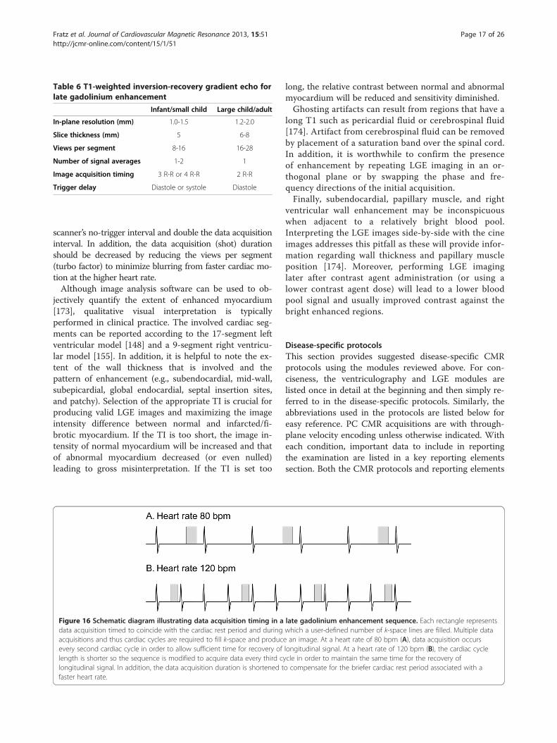
Table 6 T1-weighted inversion-recovery gradient echo forlate gadolinium enhancement
Infant/small child Large child/adult
In-plane resolution (mm) 1.0-1.5 1.2-2.0
Slice thickness (mm) 5 6-8
Views per segment 8-16 16-28
Number of signal averages 1-2 1
Image acquisition timing 3 R-R or 4 R-R 2 R-R
Trigger delay Diastole or systole Diastole
Fratz et al. Journal of Cardiovascular Magnetic Resonance 2013, 15:51 Page 17 of 26http://jcmr-online.com/content/15/1/51
scanner’s no-trigger interval and double the data acquisitioninterval. In addition, the data acquisition (shot) durationshould be decreased by reducing the views per segment(turbo factor) to minimize blurring from faster cardiac mo-tion at the higher heart rate.Although image analysis software can be used to ob-
jectively quantify the extent of enhanced myocardium[173], qualitative visual interpretation is typicallyperformed in clinical practice. The involved cardiac seg-ments can be reported according to the 17-segment leftventricular model [148] and a 9-segment right ventricu-lar model [155]. In addition, it is helpful to note the ex-tent of the wall thickness that is involved and thepattern of enhancement (e.g., subendocardial, mid-wall,subepicardial, global endocardial, septal insertion sites,and patchy). Selection of the appropriate TI is crucial forproducing valid LGE images and maximizing the imageintensity difference between normal and infarcted/fi-brotic myocardium. If the TI is too short, the image in-tensity of normal myocardium will be increased and thatof abnormal myocardium decreased (or even nulled)leading to gross misinterpretation. If the TI is set too
Figure 16 Schematic diagram illustrating data acquisition timing in adata acquisition timed to coincide with the cardiac rest period and duringacquisitions and thus cardiac cycles are required to fill k-space and producevery second cardiac cycle in order to allow sufficient time for recovery oflength is shorter so the sequence is modified to acquire data every third clongitudinal signal. In addition, the data acquisition duration is shortened tfaster heart rate.
long, the relative contrast between normal and abnormalmyocardium will be reduced and sensitivity diminished.Ghosting artifacts can result from regions that have a
long T1 such as pericardial fluid or cerebrospinal fluid[174]. Artifact from cerebrospinal fluid can be removedby placement of a saturation band over the spinal cord.In addition, it is worthwhile to confirm the presenceof enhancement by repeating LGE imaging in an or-thogonal plane or by swapping the phase and fre-quency directions of the initial acquisition.Finally, subendocardial, papillary muscle, and right
ventricular wall enhancement may be inconspicuouswhen adjacent to a relatively bright blood pool.Interpreting the LGE images side-by-side with the cineimages addresses this pitfall as these will provide infor-mation regarding wall thickness and papillary muscleposition [174]. Moreover, performing LGE imaginglater after contrast agent administration (or using alower contrast agent dose) will lead to a lower bloodpool signal and usually improved contrast against thebright enhanced regions.
Disease-specific protocolsThis section provides suggested disease-specific CMRprotocols using the modules reviewed above. For con-ciseness, the ventriculography and LGE modules arelisted once in detail at the beginning and then simply re-ferred to in the disease-specific protocols. Similarly, theabbreviations used in the protocols are listed below foreasy reference. PC CMR acquisitions are with through-plane velocity encoding unless otherwise indicated. Witheach condition, important data to include in reportingthe examination are listed in a key reporting elementssection. Both the CMR protocols and reporting elements
late gadolinium enhancement sequence. Each rectangle representswhich a user-defined number of k-space lines are filled. Multiple datae an image. At a heart rate of 80 bpm (A), data acquisition occurslongitudinal signal. At a heart rate of 120 bpm (B), the cardiac cycleycle in order to maintain the same time for the recovery ofo compensate for the briefer cardiac rest period associated with a
Fratz et al. Journal of Cardiovascular Magnetic Resonance 2013, 15:51 Page 18 of 26http://jcmr-online.com/content/15/1/51
are meant as a guide; the authors recognize that a varietyof approaches may be applied to yield a comprehensiveexamination and report.
Ventriculography module (see ventriculography sectionabove for details)
� Standard imaging
1. Cine CMR: left ventricular 2-chamber and 3-chamber views, right ventricular 3-chamber view,4-chamber view (Figure 6)
2. Cine CMR: stack of contiguous slices tocompletely encompass both ventricles planned ina ventricular short-axis and/or axial orientation(Figure 7)
� Key reporting elements: left and right ventricularend-diastolic and end-systolic volume, strokevolume, ejection fraction, and mass; regional wallmotion abnormalities
LGE module (see LGE section above for details)
� Standard imaging
1. LGE imaging in left ventricular 2-chamber and 3-chamber views, right ventricular 3-chamber view,4-chamber view
2. LGE imaging with a stack of contiguous slices tocompletely encompass both ventricles planned ina ventricular short-axis or axial orientation
3. LGE imaging in an orthogonal plane to confirmLGE if present
� Key reporting elements: location, extent andthickness of LGE
Coarctation of the aorta, before or after repair
� Standard imaging
1. Cine CMR: long-axis aortic arch plane (Figure 1)2. Ventriculography module3. CE-MRA or 3D SSFP to image the thoracicvasculature4. PC CMR: AAo, MPA, DAo at the level of the
diaphragm� Additional case-specific/comprehensive imaging
1. Spin echo: long-axis aortic arch plane (Figure 1)2. Cine CMR: short-axis aortic root plane for valve
morphology3. PC CMR: quantification of collateral aortic flow
by measuring proximal or just distal to thecoarctation, and in the descending aorta at thelevel of the diaphragm
4. LGE module� Key reporting elements: location, dimensions, and
severity of aortic obstruction; arch sidedness and
branching order; presence of aneurysm,dissection, or collateral vessels to the DAo;ventricular parameters including left ventricularmass; aortic valve morphology, stenosis,and regurgitation
D-loop transposition of the great arteries following anarterial switch operation
� Standard imaging
1. Ventriculography module2. Cine CMR: long-axis of the right ventricularoutflow tract plane3. Cine CMR: oblique axial stack to image the PAs4. CE-MRA or 3D SSFP to image the thoracic
vasculature5. PC CMR: AAo, MPA, branch PAs
� Additional case-specific/comprehensive imaging1. 3D SSFP: coronary artery origins and proximal
course2. Vasodilator perfusion module3. LGE module
� Key reporting elements: location and severity ofAAo, MPA, and branch PA obstruction; branch PAflow distribution; proximal coronary artery patencyand course; aortic root dilation; aortic andpulmonary regurgitation; ventricular parameters
D-loop transposition of the great arteries following anatrial switch operation
� Standard imaging
1. Cine CMR: axial stack from the mid-liver to thetop of the aortic arch2. Ventriculography module3. Cine CMR: oblique planes to image the SVC and
IVC pathways in long-axis4. CE-MRA or 3D SSFP to image the thoracic
vasculature, and systemic and pulmonary venousbaffles (Figure 4)
5. PC CMR: AAo, MPA, branch PAs, tricuspid andmitral valves
� Additional case-specific/comprehensive imaging1. LGE module2. PC CMR: SVC distal to the azygous vein and IVC
when systemic venous obstruction is suspected.� Key reporting elements: location and severity of
systemic and pulmonary venous pathwayobstruction, atrial baffle leak, ventricular parameters,severity and mechanism of left or right ventricularoutflow tract obstruction, tricuspid regurgitation,Qp/Qs, branch pulmonary artery flow distribution,SVC/IVC flow ratio as an indicator of systemicpathway obstruction
Fratz et al. Journal of Cardiovascular Magnetic Resonance 2013, 15:51 Page 19 of 26http://jcmr-online.com/content/15/1/51
Tetralogy of Fallot following complete repair
� Standard imaging
1. Ventriculography module2. Cine CMR: stack of images parallel to the long-axis of the right ventricular outflow tract andpulmonary valve
3. Cine CMR: oblique axial stack to image the PAs4. CE-MRA or 3D SSFP to image the thoracic
vasculature5. PC CMR: AAo, MPA, branch PAs
� Additional case-specific/comprehensive imaging1. LGE module2. PC CMR: tricuspid and mitral valves
� Key reporting elements: location and severity ofright ventricular outflow tract and pulmonary arteryobstruction, branch pulmonary artery flowdistribution, pulmonary regurgitation, atrial andventricular septal defects, Qp/Qs, ventricularparameters including RV volumes and ejectionfraction
Secundum atrial septal defect
� Standard imaging
Figulargsupto v
1. Cine CMR: stack of contiguous thin slices in a 4-chamber plane to completely encompass theatrial septum
2. Cine CMR: stack of contiguous thin slices in anoblique sagittal plane perpendicular to the atrial
re 17 Secundum atrial septal defect (ASD) imaging protocol. A. Ae secundum ASD (white arrow). B. The axial SSFP image is used to planerior and inferior defect margins. C. The axial and oblique sagittal imagisualize the ASD flow en face. This provides insight into the oval shape
septum to completely encompass the atrialseptum (Figure 17)
3. Ventriculography module4. PC CMR: AAo, MPA
� Additional case-specific/comprehensive imaging1. PC CMR: 1–3 contiguous slices positioned
parallel to the atrial septal plane to obtain anen face view of the defect (Figure 17), and withthrough-plane velocity encoding
2. PC CMR: stack of contiguous thin slices in a 4-chamber plane and/or in an oblique sagittal planeperpendicular to the atrial septum to completelyencompass the atrial septum, and with in-planevelocity encoding in the direction of atrial septaldefect flow
3. CE-MRA or 3D SSFP to image the thoracicvasculature
� Key reporting elements: number and location of thedefects, defect rim measurements, ventricularparameters, Qp/Qs
Partially anomalous pulmonary venous connection, beforeor after repair
� Standard imaging
xial sta sta
es areof the
1. Cine CMR: axial stack from the mid-abdomen tothe top of the aortic arch
2. Cine CMR: oblique plane to image the anomalousvein(s) in long-axis
3. Ventriculography module
eady-state free precession (SSFP) image in a 10-year-old with ack of oblique sagittal SSFP images to visualize the ASD and theused together to plan a stack of phase-contrast (PC) cine imagesdefect and may demonstrate additional ASDs.

Figure 18 Sinus venosus septal defect imaging protocol. A. Axial steady-state free precession (SSFP) cine image in a 22-year-old with a largesinus venosus septal defect (white arrow). B. The axial SSFP image is used to plan a stack of oblique sagittal SSFP cine images to visualize thedefect in an orthogonal view and assess its superoinferior dimension.
Fratz et al. Journal of Cardiovascular Magnetic Resonance 2013, 15:51 Page 20 of 26http://jcmr-online.com/content/15/1/51
4. CE-MRA or 3D SSFP to image the thoracicvasculature (Figure 3)
5. PC CMR: AAo, MPA, branch PAs� Additional case-specific/comprehensive imaging
1. PC CMR: anomalous vein� Key reporting elements: number, location, and drainage
of the pulmonary veins; ventricular parameters; Qp/Qs,branch pulmonary artery flow distribution
Sinus venosus septal defect
� Standard imaging
1. Cine CMR: axial stack from the mid-liver to thetop of the aortic arch2. Cine CMR: oblique sagittal plane perpendicular
to the plane of the defect (Figure 18)3. Ventriculography module4. CE-MRA or 3D SSFP to image the thoracic
vasculature5. PC CMR: AAo, MPA
� Key reporting elements: location and size of thedefect, drainage of the right pulmonary veins,
Figure 19 Ebstein anomaly imaging protocol. A. Right ventricular 3-cha-old with Ebstein anomaly. In this example, the functional tricuspid valve poutflow tract (white arrow). B. The RV 3C image is used to plan a stack of canatomic assessment or flow quantification.
ventricular parameters, Qp/Qs based on flowmeasurements
Ebstein anomaly of the tricuspid valve
� Standard imaging
mlanin
1. Cine CMR: axial stack from the diaphragm to thetop of the aortic arch
2. Ventriculography module with multiplecontiguous slices in the right ventricular3-chamber view and in the 4-chamber view
3. PC CMR: AAo, MPA, tricuspid valve,mitral valve
� Additional case-specific/comprehensive imaging1. Cine CMR: contiguous stack oriented parallel to
the functional tricuspid valve plane to visualizethe valve en face (Figure 19)
2. CE-MRA or 3D SSFP to image the thoracicvasculature
� Key reporting elements: description of tricuspidvalve morphology, tricuspid regurgitation andstenosis, pulmonary stenosis, ventricular
ber view (RV 3C) steady-state free precession cine image in a 22-yeare is displaced and inflow is directed into the right ventriculare images to visualize the displaced tricuspid valve orifice en face for
Fratz et al. Journal of Cardiovascular Magnetic Resonance 2013, 15:51 Page 21 of 26http://jcmr-online.com/content/15/1/51
parameters, presence of an atrial septal defect,Qp/Qs based on flow measurements
Functional single ventricle following a stage 1 or 2 palliation
� Standard imaging
1. Cine CMR: axial stack from the mid-liver to thetop of the aortic arch2. Ventriculography module3. CE-MRA or 3D SSFP to image the thoracic
vasculature and surgical shunts4. PC CMR: AAo, native MPA, branch PAs
� Additional case-specific/comprehensive imaging1. LGE module2. Cine CMR: long-axis aortic arch plane3. Spin echo: axial plane to image the branch PAs
and aortopulmonary shunt4. PC CMR: SVC, IVC, tricuspid and mitral valves,
DAo at the level of the diaphragm, pulmonary veins� Key reporting elements: shunt, branch PA,
pulmonary vein, and aortic arch obstruction;ventricular parameters; valve regurgitation;aortopulmonary collaterals; venous collaterals
Functional single ventricle following a Fontan operation
� Standard imaging
1. Cine CMR: axial stack from the mid-liver to thetop of the aortic arch2. Cine CMR: coronal or oblique stack to image the
Fontan baffle in long-axis3. Ventriculography module4. CE-MRA or 3D SSFP to image the thoracic
vasculature5. PC CMR: AAo, native MPA, branch PAs,
SVC, IVC� Additional case-specific/comprehensive imaging
1. Cine CMR: long-axis aortic arch plane2. LGE module3. PC CMR: tricuspid and mitral valves,
pulmonary veins� Key reporting elements: Fontan pathway, SVC,
IVC, branch PA, pulmonary vein, and aortic archobstruction; Fontan baffle defects; ventricularparameters; valve regurgitation; aortopulmonarycollaterals
Abbreviations2C: 2-chamber; 2D: 2-dimensional; 3C: 3-chamber; 4C: 4-chamber; 3D: 3-dimensional; AAo: Ascending aorta; ASD: Atrial septal defect; CE-MRA: Contrast-enhanced magnetic resonance angiography; CHD: Congenitalheart disease; CMR: Cardiovascular magnetic resonance; DAo: Descendingaorta; ECG: Electrocardiogram; GBCA: Gadolinium-based contrast agents;LGE: Late gadolinium enhancement; LV: Left ventricle; IVC: Inferior vena cava;MPA: Main pulmonary artery; MR: Magnetic resonance; MRA: Magneticresonance angiography; NSF: Nephrogenic systemic fibrosis; PAs: Pulmonary
arteries; PC CMR: Velocity-encoded phase-contrast cine CMR; Qp/Qs: Pulmonary-to-systemic flow ratio; RV: Right ventricle; RVOT: Rightventricular outflow tract; SA: Short-axis; SSFP: Steady-state free precession;SVC: Superior vena cava; TE: Echo time; TFE: Turbo field echo; TI: Inversiontime; TR: Repetition time; venc: Velocity encoding range.
Competing interestsThe authors declare that they have no competing interests.
Authors’ contributionsSF drafted and conceived of the review, designed the initial structure of themanuscript, coordinated author communication, and revised the authors’contributions to produce the draft version of the manuscript; TC drafted theventriculography section; GFG drafted the contrast-enhanced MRA and 3DSSFP sections; MMS provided extensive editorial assistance; AMT drafted ofthe vasodilator perfusion section; ERVB drafted the sedation section; SJYdrafted the blood velocity and flow measurement section; AJP drafted theLGE and patient preparation sections, and revised and synthesized all of theauthors’ contributions to produce the final version of the manuscript. Allauthors contributed substantially to the design of the review, criticallyrevised the manuscript for important intellectual content, and read andapproved the final manuscript.
AcknowledgementsThe authors thank Mark A. Fogel, MD, from The Children’s Hospital ofPhiladelphia, PA, USA, for critically reviewing the final version of themanuscript. All authors were supported by their institutions, respectively. TheSociety of Cardiovascular Magnetic Resonance funded a large portion of thetelephone communications during the drafting process. The authors thankEmily Harris for her assistance with the preparation of the figures.
Author details1Department of Pediatric Cardiology and Congenital Heart Disease,Deutsches Herzzentrum München (German Heart Center Munich) of theTechnical University Munich, Munich, Germany. 2Department of DiagnosticImaging, Children’s Hospital & Research Center Oakland, Oakland, California,USA. 3Department of Pediatric Cardiology, Evelina Children’s Hospital/Guy’sand St. Thomas’ Hospital NHS Foundation Trust; Division of Imaging Sciences& Biomedical Engineering, King’s College London, London, UK. 4The HermaHeart Center, Children’s Hospital of Wisconsin, Medical College of Wisconsin,Milwaukee, WI, USA. 5Centre for Cardiovascular Imaging, UCL Institute ofCardiovascular Science, & Great Ormond Street Hospital for Children, London,UK. 6Division of Cardiology, University Children’s Hospital Zurich, Zurich,Switzerland. 7Department of Diagnostic Imaging and Division of Cardiology,Department of Paediatrics, Hospital for Sick Children, University of Toronto,Toronto, Ontario, Canada. 8Department of Cardiology, Boston Children’sHospital, and the Department of Pediatrics, Harvard Medical School, Boston,MA, USA.
Received: 9 April 2013 Accepted: 8 May 2013Published: 13 June 2013
References1. Weber OM, Higgins CB. MR Evaluation of Cardiovascular Physiology in
Congenital Heart Disease: Flow and Function. J Cardiovasc Magn Reson.2006; 8:607–17.
2. Crean A. Cardiovascular MR and CT in congenital heart disease. Heart.2007; 93:1637–47.
3. Fratz S, Hess J, Schuhbaeck A, Buchner C, Hendrich E, Martinoff S, Stern H.Routine clinical cardiovascular magnetic resonance in paediatric andadult congenital heart disease: patients, protocols, questions asked andcontributions made. J Cardiovasc Magn Reson. 2008; 10:46.
4. Bailliard F, Hughes ML, Taylor AM. Introduction to cardiac imaging ininfants and children: techniques, potential, and role in the imagingwork-up of various cardiac malformations and other pediatric heartconditions. Eur J Radiol. 2008; 68:191–98.
5. Marcotte F, Poirier N, Pressacco J, Paquet E, Mercier LA, Dore A, Ibrahim R,Khairy P. Evaluation of adult congenital heart disease by cardiacmagnetic resonance imaging. Congenit Heart Dis. 2009; 4:216–30.

Fratz et al. Journal of Cardiovascular Magnetic Resonance 2013, 15:51 Page 22 of 26http://jcmr-online.com/content/15/1/51
6. Prakash A, Powell AJ, Geva T. Multimodality noninvasive imaging forassessment of congenital heart disease. Circ Cardiovasc Imaging. 2010;3:112–25.
7. Kilner PJ, Geva T, Kaemmerer H, Trindade PT, Schwitter J, Webb GD.Recommendations for cardiovascular magnetic resonance in adults withcongenital heart disease from the respective working groups of theEuropean Society of Cardiology. Eur Heart J. 2010; 31:794–805.
8. Zikria JF, Machnicki S, Rhim E, Bhatti T, Graham RE. MRI of patients withcardiac pacemakers: a review of the medical literature. AJR Am JRoentgenol. 2011; 196:390–401.
9. Levine GN, Gomes AS, Arai AE, Bluemke DA, Flamm SD, Kanal E, ManningWJ, Martin ET, Smith JM, Wilke N, Shellock FS. Safety of magneticresonance imaging in patients with cardiovascular devices: an AmericanHeart Association scientific statement from the Committee onDiagnostic and Interventional Cardiac Catheterization, Council onClinical Cardiology, and the Council on Cardiovascular Radiology andIntervention: endorsed by the American College of CardiologyFoundation, the North American Society for Cardiac Imaging, and theSociety for Cardiovascular Magnetic Resonance. Circulation. 2007;116:2878–91.
10. Shellock FG, Spinazzi A. MRI Safety Update 2008: Part 2, ScreeningPatients for MRI. Am J Roentgenol. 2008; 191:1140–49.
11. Fogel MA, Pawlowski TW, Harris MA, Whitehead KK, Keller MS, Wilson J,Tipton D, Harris C. Comparison and usefulness of cardiac magneticresonance versus computed tomography in infants six months of age oryounger with aortic arch anomalies without deep sedation oranesthesia. Am J Cardiol. 2011; 108:120–25.
12. Windram J, Grosse-Wortmann L, Shariat M, Greer ML, Crawford MW, Yoo SJ.Cardiovascular MRI without sedation or general anesthesia using a feed-and-sleep technique in neonates and infants. Pediatr Radiol. 2011; 42:183–87.
13. Odegard KC, DiNardo JA, Tsai-Goodman B, Powell AJ, Geva T, Laussen PC.Anaesthesia considerations for cardiac MRI in infants and small children.Paediatr Anaesth. 2004; 14:471–76.
14. Dorfman AL, Odegard KC, Powell AJ, Laussen PC, Geva T. Risk factors foradverse events during cardiovascular magnetic resonance in congenitalheart disease. J Cardiovasc Magn Reson. 2007; 9:793–98.
15. Osborn I. Magnetic resonance imaging anesthesia: new challenges andtechniques. Curr Opin Anaesthesiol. 2002; 15:443–48.
16. Fogel MA, Weinberg PM, Parave E, Harris C, Montenegro L, Harris MA,Concepcion M. Deep sedation for cardiac magnetic resonance imaging: acomparison with cardiac anesthesia. J Pediatr. 2008; 152:534–39. 539 e531.
17. Didier D, Ratib O, Beghetti M, Oberhaensli I, Friedli B. Morphologic andfunctional evaluation of congenital heart disease by magnetic resonanceimaging. J Magn Reson Imaging. 1999; 10:639–55.
18. Sarikouch S, Schaeffler R, Korperich H, Dongas A, Haas NA, Beerbaum P.Cardiovascular magnetic resonance imaging for intensive care infants:safe and effective? Pediatr Cardiol. 2009; 30:146–52.
19. Runge VM. Safety of approved MR contrast media for intravenousinjection. J Magn Reson Imaging. 2000; 12:205–13.
20. Prince MR, Zhang H, Zou Z, Staron RB, Brill PW. Incidence of immediategadolinium contrast media reactions. AJR Am J Roentgenol. 2011;196:W138–143.
21. Dillman JR, Ellis JH, Cohan RH, Strouse PJ, Jan SC. Frequency and severityof acute allergic-like reactions to gadolinium-containing i.v. contrastmedia in children and adults. AJR Am J Roentgenol. 2007; 189:1533–38.
22. ACR Manual on Contrast Media Version 9. 2013. http://www.acr.org/Quality-Safety/Resources/Contrast-Manual.
23. Leiner T, Kucharczyk W. NSF prevention in clinical practice: summary ofrecommendations and guidelines in the United States, Canada, andEurope. J Magn Reson Imaging. 2009; 30:1357–63.
24. Penfield JG. Nephrogenic systemic fibrosis and the use of gadolinium-based contrast agents. Pediatr Nephrol. 2008; 23:2121–29.
25. Zou Z, Zhang HL, Roditi GH, Leiner T, Kucharczyk W, Prince MR.Nephrogenic systemic fibrosis: review of 370 biopsy-confirmed cases.JACC Cardiovasc Imaging. 2011; 4:1206–16.
26. Bernstein MA, Huston J 3rd, Ward HA. Imaging artifacts at 3.0T. J MagnReson Imaging. 2006; 24:735–46.
27. Mueller A, Kouwenhoven M, Naehle CP, Gieseke J, Strach K, Willinek WA,Schild HH, Thomas D. Dual-source radiofrequency transmission withpatient-adaptive local radiofrequency shimming for 3.0-T cardiac MRimaging: initial experience. Radiology. 2012; 263:77–85.
28. Garg R, Powell AJ, Sena L, Marshall AC, Geva T. Effects of metallic implantson magnetic resonance imaging evaluation of Fontan palliation. Am JCardiol. 2005; 95:688–91.
29. Masui T, Katayama M, Kobayashi S, Ito T, Seguchi M, Koide M, Nozaki A,Sakahara H. Gadolinium-enhanced MR angiography in the evaluation ofcongenital cardiovascular disease pre- and postoperative states ininfants and children. J Magn Reson Imaging. 2000; 12:1034–42.
30. Prasad SK, Soukias N, Hornung T, Khan M, Pennell DJ, Gatzoulis MA,Mohiaddin RH. Role of magnetic resonance angiography in the diagnosisof major aortopulmonary collateral arteries and partial anomalouspulmonary venous drainage. Circulation. 2004; 109:207–14.
31. Ferrari VA, Scott CH, Holland GA, Axel L, Sutton MS. Ultrafast three-dimensional contrast-enhanced magnetic resonance angiography andimaging in the diagnosis of partial anomalous pulmonary venousdrainage. J Am Coll Cardiol. 2001; 37:1120–28.
32. Valsangiacomo Buchel ER, DiBernardo S, Bauersfeld U, Berger F.Contrast-enhanced magnetic resonance angiography of the great arteriesin patients with congenital heart disease: an accurate tool for planningcatheter-guided interventions. Int J Cardiovasc Imaging. 2005; 21:313–22.
33. Geva T, Greil GF, Marshall AC, Landzberg M, Powell AJ. Gadolinium-enhanced3-dimensional magnetic resonance angiography of pulmonary bloodsupply in patients with complex pulmonary stenosis or atresia: comparisonwith x-ray angiography. Circulation. 2002; 106:473–78.
34. Greil GF, Powell AJ, Gildein HP, Geva T. Gadolinium-enhanced three-dimensional magnetic resonance angiography of pulmonary andsystemic venous anomalies. J Am Coll Cardiol. 2002; 39:335–41.
35. Saleh RS, Patel S, Lee MH, Boechat MI, Ratib O, Saraiva CR, Finn JP.Contrast-enhanced MR angiography of the chest and abdomen withuse of controlled apnea in children. Radiology. 2007; 243:837–46.
36. Mohrs OK, Petersen SE, Voigtlaender T, Peters J, Nowak B, Heinemann MK,Kauczor HU. Time-resolved contrast-enhanced MR angiography of thethorax in adults with congenital heart disease. AJR Am J Roentgenol. 2006;187:1107–14.
37. Fenchel M, Saleh R, Dinh H, Lee MH, Nael K, Krishnam M, Ruehm SG, Miller S,Child J, Finn JP. Juvenile and adult congenital heart disease: time-resolved 3Dcontrast-enhanced MR angiography. Radiology. 2007; 244:399–410.
38. Goo HW, Yang DH, Park IS, Ko JK, Kim YH, Seo DM, Yun TJ, Park JJ.Time-resolved three-dimensional contrast-enhanced magneticresonance angiography in patients who have undergone a Fontanoperation or bidirectional cavopulmonary connection: initial experience.J Magn Reson Imaging. 2007; 25:727–36.
39. Muthupillai R, Vick GW 3rd, Flamm SD, Chung T. Time-resolved contrast-enhanced magnetic resonance angiography in pediatric patients usingsensitivity encoding. J Magn Reson Imaging. 2003; 17:559–64.
40. Sorensen TS, Korperich H, Greil GF, Eichhorn J, Barth P, Meyer H, PedersenEM, Beerbaum P. Operator-independent isotropic three-dimensionalmagnetic resonance imaging for morphology in congenital heartdisease: a validation study. Circulation. 2004; 110:163–69.
41. Razavi RS, Hill DL, Muthurangu V, Miquel ME, Taylor AM, Kozerke S, Baker EJ.Three-dimensional magnetic resonance imaging of congenital cardiacanomalies. Cardiol Young. 2003; 13:461–65.
42. Fenchel M, Greil GF, Martirosian P, Kramer U, Schick F, Claussen CD,Sieverding L, Miller S. Three-dimensional morphological magneticresonance imaging in infants and children with congenital heart disease.Pediatr Radiol. 2006; 36:1265–72.
43. Beerbaum P, Sarikouch S, Laser KT, Greil G, Burchert W, Korperich H.Coronary anomalies assessed by whole-heart isotropic 3D magneticresonance imaging for cardiac morphology in congenital heart disease.J Magn Reson Imaging. 2009; 29:320–27.
44. Rajiah P, Setser RM, Desai MY, Flamm SD, Arruda JL. Utility of free-breathing, whole-heart, three-dimensional magnetic resonance imagingin the assessment of coronary anatomy for congenital heart disease.Pediatr Cardiol. 2011; 32:418–25.
45. Su JT, Chung T, Muthupillai R, Pignatelli RH, Kung GC, Diaz LK, Vick GW 3rd,Kovalchin JP. Usefulness of real-time navigator magnetic resonanceimaging for evaluating coronary artery origins in pediatric patients. Am JCardiol. 2005; 95:679–82.
46. Tangcharoen T, Bell A, Hegde S, Hussain T, Beerbaum P, Schaeffter T, RazaviR, Botnar RM, Greil GF. Detection of coronary artery anomalies in infantsand young children with congenital heart disease by using MR imaging.Radiology. 2011; 259:240–47.

Fratz et al. Journal of Cardiovascular Magnetic Resonance 2013, 15:51 Page 23 of 26http://jcmr-online.com/content/15/1/51
47. Plathow C, Ley S, Zaporozhan J, Schobinger M, Gruenig E, Puderbach M,Eichinger M, Meinzer HP, Zuna I, Kauczor HU. Assessment ofreproducibility and stability of different breath-hold maneuvers bydynamic MRI: comparison between healthy adults and patients withpulmonary hypertension. Eur Radiol. 2006; 16:173–79.
48. Holland AE, Goldfarb JW, Edelman RR. Diaphragmatic and cardiac motionduring suspended breathing: preliminary experience and implicationsfor breath-hold MR imaging. Radiology. 1998; 209:483–89.
49. Foo TK, Bernstein MA, Aisen AM, Hernandez RJ, Collick BD, Bernstein T.Improved ejection fraction and flow velocity estimates with use of viewsharing and uniform repetition time excitation with fast cardiactechniques. Radiology. 1995; 195:471–78.
50. Robbers-Visser D, Boersma E, Helbing WA. Normal biventricular function,volumes, and mass in children aged 8 to 17 years. J Magn Reson Imaging.2009; 29:552–59.
51. Fratz S, Schuhbaeck A, Buchner C, Busch R, Meierhofer C, Martinoff S, Hess J,Stern H. Comparison of accuracy of axial slices versus short-axis slices formeasuring ventricular volumes by cardiac magnetic resonance inpatients with corrected tetralogy of fallot. Am J Cardiol. 2009;103:1764–69.
52. Sarikouch S, Peters B, Gutberlet M, Leismann B, Kelter-Kloepping A,Koerperich H, Kuehne T, Beerbaum P. Sex-specific pediatric percentiles forventricular size and mass as reference values for cardiac MRI:assessment by steady-state free-precession and phase-contrast MRI flow.Circ Cardiovasc Imaging. 2010; 3:65–76.
53. Buechel EV, Kaiser T, Jackson C, Schmitz A, Kellenberger CJ. Normal right-and left ventricular volumes and myocardial mass in children measuredby steady state free precession cardiovascular magnetic resonance.J Cardiovasc Magn Reson. 2009; 11:19.
54. Alfakih K, Plein S, Bloomer T, Jones T, Ridgway J, Sivananthan M.Comparison of right ventricular volume measurements between axialand short axis orientation using steady-state free precession magneticresonance imaging. J Magn Reson Imaging. 2003; 18:25–32.
55. Fratz S, Janello C, Muller D, Seligmann M, Meierhofer C, Schuster T,Schreiber C, Martinoff S, Hess J, Kuhn A, et al. The functional right ventricleand tricuspid regurgitation in Ebstein’s anomaly. Int J Cardiol. 2013;167:258–61.
56. Mooij CF, de Wit CJ, Graham DA, Powell AJ, Geva T. Reproducibility of MRImeasurements of right ventricular size and function in patients withnormal and dilated ventricles. J Magn Reson Imaging. 2008; 28:67–73.
57. Kirschbaum SW, Baks T, Gronenschild EH, Aben JP, Weustink AC, Wielopolski PA,Krestin GP, de Feyter PJ, van Geuns RJ. Addition of the long-axis information toshort-axis contours reduces interstudy variability of left-ventricular analysis incardiac magnetic resonance studies. Invest Radiol. 2008; 43:1–6.
58. Winter MM, Bernink FJ, Groenink M, Bouma BJ, van Dijk AP, Helbing WA,Tijssen JG, Mulder BJ. Evaluating the systemic right ventricle by CMR: theimportance of consistent and reproducible delineation of the cavity.J Cardiovasc Magn Reson. 2008; 10:40.
59. Sievers B, Kirchberg S, Bakan A, Franken U, Trappe HJ. Impact of papillarymuscles in ventricular volume and ejection fraction assessment bycardiovascular magnetic resonance. J Cardiovasc Magn Reson. 2004; 6:9–16.
60. Papavassiliu T, Kuhl HP, Schroder M, Suselbeck T, Bondarenko O, Bohm CK,Beek A, Hofman MM, van Rossum AC. Effect of endocardial trabeculae onleft ventricular measurements and measurement reproducibility atcardiovascular MR imaging. Radiology. 2005; 236:57–64.
61. Janik M, Cham MD, Ross MI, Wang Y, Codella N, Min JK, Prince MR,Manoushagian S, Okin PM, Devereux RB, Weinsaft JW. Effects of papillarymuscles and trabeculae on left ventricular quantification: increasedimpact of methodological variability in patients with left ventricularhypertrophy. J Hypertens. 2008; 26:1677–85.
62. Alfakih K, Plein S, Thiele H, Jones T, Ridgway JP, Sivananthan MU. Normalhuman left and right ventricular dimensions for MRI as assessed byturbo gradient echo and steady-state free precession imagingsequences. J Magn Reson Imaging. 2003; 17:323–29.
63. Hudsmith LE, Petersen SE, Francis JM, Robson MD, Neubauer S. Normalhuman left and right ventricular and left atrial dimensions using steadystate free precession magnetic resonance imaging. J Cardiovasc MagnReson. 2005; 7:775–82.
64. Sluysmans T, Colan SD. Theoretical and empirical derivation ofcardiovascular allometric relationships in children. J Appl Physiol. 2005;99:445–57.
65. Dewey FE, Rosenthal D, Murphy DJ Jr, Froelicher VF, Ashley EA. Does sizematter? Clinical applications of scaling cardiac size and function forbody size. Circulation. 2008; 117:2279–87.
66. Luijnenburg SE, Robbers-Visser D, Moelker A, Vliegen HW, Mulder BJ,Helbing WA. Intra-observer and interobserver variability of biventricularfunction, volumes and mass in patients with congenital heart diseasemeasured by CMR imaging. Int J Cardiovasc Imaging. 2010; 26:57–64.
67. Beerbaum P, Barth P, Kropf S, Sarikouch S, Kelter-Kloepping A, Franke D,Gutberlet M, Kuehne T. Cardiac function by MRI in congenital heartdisease: impact of consensus training on interinstitutional variance.J Magn Reson Imaging. 2009; 30:956–66.
68. Blalock SE, Banka P, Geva T, Powell AJ, Zhou J, Prakash A. Interstudyvariability in cardiac magnetic resonance imaging measurements ofventricular volume, mass, and ejection fraction in repaired tetralogy ofFallot: A prospective observational study. J Magn Reson Imaging. 2013.doi:10.1002/jmri.24050.
69. Buechel ER, Dave HH, Kellenberger CJ, Dodge-Khatami A, Pretre R, Berger F,Bauersfeld U. Remodelling of the right ventricle after early pulmonaryvalve replacement in children with repaired tetralogy of Fallot:assessment by cardiovascular magnetic resonance. Eur Heart J. 2005;26:2721–27.
70. Powell AJ, Geva T. Blood Flow Measurement by Magnetic ResonanceImaging in Congenital Heart Disease. Pediatr Cardiol. 2000; 21:47–58.
71. Lotz J, Meier C, Leppert A, Galanski M. Cardiovascular flow measurementwith phase-contrast MR imaging: basic facts and implementation.RadioGraphics. 2002; 22:651–71.
72. Gatehouse PD, Keegan J, Crowe LA, Masood S, Mohiaddin RH, Kreitner KF,Firmin DN. Applications of phase-contrast flow and velocity imaging incardiovascular MRI. Eur Radiol. 2005; 15:2172–84.
73. Chai P, Mohiaddin R. How we perform cardiovascular magneticresonance flow assessment using phase-contrast velocity mapping.J Cardiovasc Magn Reson. 2005; 7:705–16.
74. Hundley WG, Li HF, Hillis LD, Meshack BM, Lange RA, Willard JE, Landau C,Peshock RM. Quantitation of cardiac output with velocity-encoded, phase-difference magnetic resonance imaging. Am J Cardiol. 1995; 75:1250–55.
75. Fratz S, Hager A, Busch R, Kaemmerer H, Schwaiger M, Lange R, Hess J,Stern HC. Patients after atrial switch operation for transposition of thegreat arteries can not increase stroke volume under dobutamine stressas opposed to patients with congenitally corrected transposition. Circ J.2008; 72:1130–35.
76. Hundley WG, Li HF, Lange RA, Pfeifer DP, Meshack BM, Willard JE, Landau C,Willett D, Hillis LD, Peshock RM. Assessment of left-to-right intracardiacshunting by velocity-encoded, phase-difference magnetic resonanceimaging. A comparison with oximetric and indicator dilution techniques.Circulation. 1995; 91:2955–60.
77. Brenner LD, Caputo GR, Mostbeck G, Steiman D, Dulce M, Cheitlin MD,O’Sullivan M, Higgins CB. Quantification of left to right atrial shunts withvelocity-encoded cine nuclear magnetic resonance imaging. J Am CollCardiol. 1992; 20:1246–50.
78. Beerbaum P, Korperich H, Barth P, Esdorn H, Gieseke J, Meyer H.Noninvasive quantification of left-to-right shunt in pediatric patients:phase-contrast cine magnetic resonance imaging compared withinvasive oximetry. Circulation. 2001; 103:2476–82.
79. Powell AJ, Maier SE, Chung T, Geva T. Phase-velocity cine magnetic resonanceimaging measurement of pulsatile blood flow in children and young adults:in vitro and in vivo validation. Pediatr Cardiol. 2000; 21:104–10.
80. Beerbaum P, Korperich H, Gieseke J, Barth P, Peuster M, Meyer H. Rapidleft-to-right shunt quantification in children by phase-contrast magneticresonance imaging combined with sensitivity encoding (SENSE).Circulation. 2003; 108:1355–61.
81. Powell AJ, Tsai-Goodman B, Prakash A, Greil GF, Geva T. Comparison betweenphase-velocity cine magnetic resonance imaging and invasive oximetry forquantification of atrial shunts. Am J Cardiol. 2003; 91:1523–25.
82. Fratz S, Hess J, Schwaiger M, Martinoff S, Stern HC. More accuratequantification of pulmonary blood flow by magnetic resonance imagingthan by lung perfusion scintigraphy in patients with fontan circulation.Circulation. 2002; 106:1510–13.
83. Roman KS, Kellenberger CJ, Farooq S, MacGowan CK, Gilday DL, Yoo SJ.Comparative imaging of differential pulmonary blood flow in patientswith congenital heart disease: magnetic resonance imaging versus lungperfusion scintigraphy. Pediatr Radiol. 2005; 35:295–301.

Fratz et al. Journal of Cardiovascular Magnetic Resonance 2013, 15:51 Page 24 of 26http://jcmr-online.com/content/15/1/51
84. Caputo GR, Kondo C, Masui T, Geraci SJ, Foster E, O’Sullivan MM, Higgins CB.Right and left lung perfusion: in vitro and in vivo validation with oblique-angle, velocity-encoded cine MR imaging. Radiology. 1991; 180:693–98.
85. Sridharan S, Derrick G, Deanfield J, Taylor AM. Assessment of differentialbranch pulmonary blood flow: a comparative study of phase contrastmagnetic resonance imaging and radionuclide lung perfusion imaging.Heart. 2006; 92:963–68.
86. Holmqvist C, Oskarsson G, Stahlberg F, Thilen U, Bjorkhem G, Laurin S.Functional evaluation of extracardiac ventriculopulmonary conduits andof the right ventricle with magnetic resonance imaging and velocitymapping. Am J Cardiol. 1999; 83:926–32.
87. Rebergen SA, van der Wall EE, Doornbos J, de Roos A. Magnetic resonancemeasurement of velocity and flow: technique, validation, andcardiovascular applications. Am Heart J. 1993; 126:1439–56.
88. Kon MW, Myerson SG, Moat NE, Pennell DJ. Quantification of regurgitantfraction in mitral regurgitation by cardiovascular magnetic resonance:comparison of techniques. J Heart Valve Dis. 2004; 13:600–07.
89. Kutty S, Whitehead KK, Natarajan S, Harris MA, Wernovsky G, Fogel MA.Qualitative echocardiographic assessment of aortic valve regurgitationwith quantitative cardiac magnetic resonance: a comparative study.Pediatr Cardiol. 2009; 30:971–77.
90. Ley S, Eichhorn J, Ley-Zaporozhan J, Ulmer H, Schenk JP, Kauczor HU,Arnold R. Evaluation of aortic regurgitation in congenital heart disease:value of MR imaging in comparison to echocardiography. Pediatr Radiol.2007; 37:426–36.
91. Sondergaard L, Lindvig K, Hildebrandt P, Thomsen C, Stahlberg F, Joen T,Henriksen O. Quantification of aortic regurgitation by magneticresonance velocity mapping. Am Heart J. 1993; 125:1081–90.
92. Niezen RA, Helbing WA, van der Wall EE, van der Geest RJ, Rebergen SA,de Roos A. Biventricular systolic function and mass studied with MRimaging in children with pulmonary regurgitation after repair fortetralogy of Fallot. Radiology. 1996; 201:135–40.
93. Dulce MC, Mostbeck GH, O’Sullivan M, Cheitlin M, Caputo GR, Higgins CB.Severity of aortic regurgitation: interstudy reproducibility ofmeasurements with velocity-encoded cine MR imaging. Radiology. 1992;185:235–40.
94. Mahle WT, Parks WJ, Fyfe DA, Sallee D. Tricuspid regurgitation in patientswith repaired Tetralogy of Fallot and its relation to right ventriculardilatation. Am J Cardiol. 2003; 92:643–45.
95. Whitehead KK, Gillespie MJ, Harris MA, Fogel MA, Rome JJ. Noninvasivequantification of systemic-to-pulmonary collateral flow: a major sourceof inefficiency in patients with superior cavopulmonary connections.Circ Cardiovasc Imaging. 2009; 2:405–11.
96. Grosse-Wortmann L, Al-Otay A, Yoo SJ. Aortopulmonary collaterals afterbidirectional cavopulmonary connection or Fontan completion:quantification with MRI. Circ Cardiovasc Imaging. 2009; 2:219–25.
97. Prakash A, Rathod RH, Powell AJ, McElhinney DB, Banka P, Geva T. Relation ofsystemic-to-pulmonary artery collateral flow in single ventricle physiology topalliative stage and clinical status. Am J Cardiol. 2012; 109:1038–45.
98. Rupprecht T, Nitz W, Wagner M, Kreissler P, Rascher W, Hofbeck M.Determination of the pressure gradient in children with coarctation ofthe aorta by low-field magnetic resonance imaging. Pediatr Cardiol. 2002;23:127–31.
99. Ebbers T, Wigstrom L, Bolger AF, Engvall J, Karlsson M. Estimation ofrelative cardiovascular pressures using time-resolved three-dimensionalphase contrast MRI. Magn Reson Med. 2001; 45:872–79.
100. Oshinski JN, Parks WJ, Markou CP, Bergman HL, Larson BE, Ku DN,Mukundan S Jr, Pettigrew RI. Improved measurement of pressuregradients in aortic coarctation by magnetic resonance imaging. J Am CollCardiol. 1996; 28:1818–26.
101. Mohiaddin RH, Kilner PJ, Rees S, Longmore DB. Magnetic resonancevolume flow and jet velocity mapping in aortic coarctation. J Am CollCardiol. 1993; 22:1515–21.
102. Sakuma H, Kawada N, Kubo H, Nishide Y, Takano K, Kato N, Takeda K. Effectof breath holding on blood flow measurement using fast velocityencoded cine MRI. Magn Reson Med. 2001; 45:346–48.
103. Johansson B, Babu-Narayan SV, Kilner PJ. The effects of breath-holding onpulmonary regurgitation measured by cardiovascular magneticresonance velocity mapping. J Cardiovasc Magn Reson. 2009; 11:1.
104. Ley S, Fink C, Puderbach M, Zaporozhan J, Plathow C, Eichinger M, HoschW, Kreitner KF, Kauczor HU. MRI Measurement of the hemodynamics of
the pulmonary and systemic arterial circulation: influence of breathingmaneuvers. AJR Am J Roentgenol. 2006; 187:439–44.
105. Prakash A, Garg R, Marcus EN, Reynolds G, Geva T, Powell AJ. Faster flowquantification using sensitivity encoding for velocity-encoded cinemagnetic resonance imaging: in vitro and in vivo validation. J MagnReson Imaging. 2006; 24:676–82.
106. Thunberg P, Karlsson M, Wigstrom L. Accuracy and reproducibility inphase contrast imaging using SENSE. Magn Reson Med. 2003; 50:1061–68.
107. Tang C, Blatter DD, Parker DL. Accuracy of phase-contrast flowmeasurements in the presence of partial-volume effects. J Magn ResonImaging. 1993; 3:377–85.
108. Hofman MB, Visser FC, van Rossum AC, Vink QM, Sprenger M, Westerhof N.In vivo validation of magnetic resonance blood volume flowmeasurements with limited spatial resolution in small vessels. MagnReson Med. 1995; 33:778–84.
109. Chatzimavroudis GP, Oshinski JN, Franch RH, Pettigrew RI, Walker PG,Yoganathan AP. Quantification of the aortic regurgitant volume withmagnetic resonance phase velocity mapping: a clinical investigation ofthe importance of imaging slice location. J Heart Valve Dis. 1998; 7:94–101.
110. Kilner PJ, Gatehouse PD, Firmin DN. Flow measurement by magneticresonance: a unique asset worth optimising. J Cardiovasc Magn Reson.2007; 9:723–28.
111. Kozerke S, Schwitter J, Pedersen EM, Boesiger P. Aortic and mitralregurgitation: quantification using moving slice velocity mapping.J Magn Reson Imaging. 2001; 14:106–12.
112. Myerson SG. Heart valve disease: investigation by cardiovascularmagnetic resonance. J Cardiovasc Magn Reson. 2012; 14:7.
113. Cawley PJ, Maki JH, Otto CM. Cardiovascular magnetic resonance imagingfor valvular heart disease: technique and validation. Circulation. 2009;119:468–78.
114. Gelfand EV, Hughes S, Hauser TH, Yeon SB, Goepfert L, Kissinger KV, RofskyNM, Manning WJ. Severity of mitral and aortic regurgitation as assessedby cardiovascular magnetic resonance: optimizing correlation withDoppler echocardiography. J Cardiovasc Magn Reson. 2006; 8:503–07.
115. Hundley WG, Li HF, Willard JE, Landau C, Lange RA, Meshack BM, Hillis LD,Peshock RM. Magnetic resonance imaging assessment of the severity ofmitral regurgitation. Comparison with invasive techniques. Circulation.1995; 92:1151–58.
116. Rebergen SA, Helbing WA, van der Wall EE, Maliepaard C, Chin JG, de,Roos A. MR velocity mapping of tricuspid flow in healthy children andin patients who have undergone Mustard or Senning repair.Radiology. 1995; 194:505–12.
117. Fujita N, Chazouilleres AF, Hartiala JJ, O’Sullivan M, Heidenreich P, Kaplan JD,Sakuma H, Foster E, Caputo GR, Higgins CB. Quantification of mitralregurgitation by velocity-encoded cine nuclear magnetic resonanceimaging. J Am Coll Cardiol. 1994; 23:951–58.
118. Kayser HW, Stoel BC, van der Wall EE, van der Geest RJ, de Roos A. MRvelocity mapping of tricuspid flow: correction for through-plane motion.J Magn Reson Imaging. 1997; 7:669–73.
119. Westenberg JJ, Roes SD, Ajmone Marsan N, Binnendijk NM, Doornbos J, BaxJJ, Reiber JH, de Roos A, van der Geest RJ. Mitral valve and tricuspid valveblood flow: accurate quantification with 3D velocity-encoded MRimaging with retrospective valve tracking. Radiology. 2008; 249:792–800.
120. Gatehouse PD, Rolf MP, Graves MJ, Hofman MB, Totman J, Werner B, Quest RA,Liu Y, von Spiczak J, Dieringer M, et al. Flow measurement by cardiovascularmagnetic resonance: a multi-centre multi-vendor study of background phaseoffset errors that can compromise the accuracy of derived regurgitant orshunt flow measurements. J Cardiovasc Magn Reson. 2010; 12:5.
121. Pelc NJ. Flow quantification and analysis methods. Magn Reson ImagingClin N Am. 1995; 3:413–24.
122. Chernobelsky A, Shubayev O, Comeau CR, Wolff SD. Baseline correction ofphase contrast images improves quantification of blood flow in thegreat vessels. J Cardiovasc Magn Reson. 2007; 9:681–85.
123. Miller TA, Landes AB, Moran AM. Improved accuracy in flow mapping ofcongenital heart disease using stationary phantom technique.J Cardiovasc Magn Reson. 2009; 11:52.
124. Holland BJ, Printz BF, Lai WW. Baseline correction of phase-contrastimages in congenital cardiovascular magnetic resonance. J CardiovascMagn Reson. 2010; 12:11.
125. van der Hulst AE, Westenberg JJ, Kroft LJ, Bax JJ, Blom NA, de Roos A, RoestAA. Tetralogy of fallot: 3D velocity-encoded MR imaging for evaluation
Fratz et al. Journal of Cardiovascular Magnetic Resonance 2013, 15:51 Page 25 of 26http://jcmr-online.com/content/15/1/51
of right ventricular valve flow and diastolic function in patients aftercorrection. Radiology. 2010; 256:724–34.
126. Hsiao A, Lustig M, Alley MT, Murphy M, Chan FP, Herfkens RJ, VasanawalaSS. Rapid pediatric cardiac assessment of flow and ventricular volumewith compressed sensing parallel imaging volumetric cine phase-contrast MRI. AJR Am J Roentgenol. 2012; 198:W250–259.
127. Hsiao A, Lustig M, Alley MT, Murphy MJ, Vasanawala SS. Evaluation ofvalvular insufficiency and shunts with parallel-imaging compressed-sensing 4D phase-contrast MR imaging with stereoscopic 3D velocity-fusion volume-rendered visualization. Radiology. 2012; 265:87–95.
128. Roes SD, Hammer S, van der Geest RJ, Marsan NA, Bax JJ, Lamb HJ, ReiberJH, de Roos A, Westenberg JJ. Flow assessment through four heart valvessimultaneously using 3-dimensional 3-directional velocity-encodedmagnetic resonance imaging with retrospective valve tracking inhealthy volunteers and patients with valvular regurgitation. Invest Radiol.2009; 44:669–75.
129. Brandts A, Bertini M, van Dijk EJ, Delgado V, Marsan NA, van der Geest RJ,Siebelink HM, de Roos A, Bax JJ, Westenberg JJ. Left ventricular diastolicfunction assessment from three-dimensional three-directional velocity-encoded MRI with retrospective valve tracking. J Magn Reson Imaging.2011; 33:312–19.
130. Schwitter J, Wacker CM, van Rossum AC, Lombardi M, Al-Saadi N, AhlstromH, Dill T, Larsson HB, Flamm SD, Marquardt M, Johansson L. MR-IMPACT:comparison of perfusion-cardiac magnetic resonance with single-photonemission computed tomography for the detection of coronary arterydisease in a multicentre, multivendor, randomized trial. Eur Heart J. 2008;29:480–89.
131. Nandalur KR, Dwamena BA, Choudhri AF, Nandalur MR, Carlos RC.Diagnostic performance of stress cardiac magnetic resonance imaging inthe detection of coronary artery disease: a meta-analysis. J Am CollCardiol. 2007; 50:1343–53.
132. Paetsch I, Jahnke C, Wahl A, Gebker R, Neuss M, Fleck E, Nagel E.Comparison of dobutamine stress magnetic resonance, adenosine stressmagnetic resonance, and adenosine stress magnetic resonanceperfusion. Circulation. 2004; 110:835–42.
133. Greenwood JP, Maredia N, Younger JF, Brown JM, Nixon J, Everett CC,Bijsterveld P, Ridgway JP, Radjenovic A, Dickinson CJ, et al. Cardiovascularmagnetic resonance and single-photon emission computed tomographyfor diagnosis of coronary heart disease (CE-MARC): a prospective trial.Lancet. 2012; 379:453–60.
134. Jahnke C, Nagel E, Gebker R, Kokocinski T, Kelle S, Manka R, Fleck E, PaetschI. Prognostic value of cardiac magnetic resonance stress tests: adenosinestress perfusion and dobutamine stress wall motion imaging. Circulation.2007; 115:1769–76.
135. Ingkanisorn WP, Kwong RY, Bohme NS, Geller NL, Rhoads KL, Dyke CK, PatersonDI, Syed MA, Aletras AH, Arai AE. Prognosis of negative adenosine stressmagnetic resonance in patients presenting to an emergency departmentwith chest pain. J Am Coll Cardiol. 2006; 47:1427–32.
136. Buechel ER, Balmer C, Bauersfeld U, Kellenberger CJ, Schwitter J. Feasibilityof perfusion cardiovascular magnetic resonance in paediatric patients.J Cardiovasc Magn Reson. 2009; 11:51.
137. Taylor AM, Dymarkowski S, De Meerleer K, Hamaekers P, Gewillig M,Mertens L, Bogaert J. Validation and application of single breath-holdcine cardiac MR for ventricular function assessment in children withcongenital heart disease at rest and during adenosine stress. J CardiovascMagn Reson. 2005; 7:743–51.
138. Manso B, Castellote A, Dos L, Casaldaliga J. Myocardial perfusion magneticresonance imaging for detecting coronary function anomalies inasymptomatic paediatric patients with a previous arterial switchoperation for the transposition of great arteries. Cardiol Young. 2010;20:410–17.
139. Prakash A, Powell AJ, Krishnamurthy R, Geva T. Magnetic resonanceimaging evaluation of myocardial perfusion and viability in congenitaland acquired pediatric heart disease. Am J Cardiol. 2004; 93:657–61.
140. Cook SC, Ferketich AK, Raman SV. Myocardial ischemia in asymptomaticadults with repaired aortic coarctation. Int J Cardiol. 2009; 133:95–101.
141. Strigl S, Beroukhim R, Valente AM, Annese D, Harrington JS, Geva T, PowellAJ. Feasibility of dobutamine stress cardiovascular magnetic resonanceimaging in children. J Magn Reson Imaging. 2009; 29:313–19.
142. Kellman P, Arai AE. Imaging sequences for first pass perfusion –a review.J Cardiovasc Magn Reson. 2007; 9:525–37.
143. Kramer CM, Barkhausen J, Flamm SD, Kim RJ, Nagel E. Standardizedcardiovascular magnetic resonance imaging (CMR) protocols, society forcardiovascular magnetic resonance: board of trustees task force onstandardized protocols. J Cardiovasc Magn Reson. 2008; 10:35.
144. Gebker R, Schwitter J, Fleck E, Nagel E. How we perform myocardialperfusion with cardiovascular magnetic resonance. J Cardiovasc MagnReson. 2007; 9:539–47.
145. Gerber BL, Raman SV, Nayak K, Epstein FH, Ferreira P, Axel L, Kraitchman DL.Myocardial first-pass perfusion cardiovascular magnetic resonance: history,theory, and current state of the art. J Cardiovasc Magn Reson. 2008; 10:18.
146. Jerosch-Herold M. Quantification of myocardial perfusion bycardiovascular magnetic resonance. J Cardiovasc Magn Reson. 2010; 12:57.
147. Klem I, Heitner JF, Shah DJ, Sketch MH Jr, Behar V, Weinsaft J, Cawley P,Parker M, Elliott M, Judd RM, Kim RJ. Improved detection of coronaryartery disease by stress perfusion cardiovascular magnetic resonancewith the use of delayed enhancement infarction imaging. J Am CollCardiol. 2006; 47:1630–38.
148. Cerqueira MD. Standardized Myocardial Segmentation and Nomenclaturefor Tomographic Imaging of the Heart: A Statement for HealthcareProfessionals From the Cardiac Imaging Committee of the Council onClinical Cardiology of the American Heart Association. Circulation. 2002;105:539–42.
149. Arai AE. Magnetic resonance first-pass myocardial perfusion imaging.Top Magn Reson Imaging. 2000; 11:383–98.
150. Amado LC, Gerber BL, Gupta SN, Rettmann DW, Szarf G, Schock R, Nasir K,Kraitchman DL, Lima JA. Accurate and objective infarct sizing by contrast-enhanced magnetic resonance imaging in a canine myocardialinfarction model. J Am Coll Cardiol. 2004; 44:2383–89.
151. Kehr E, Sono M, Chugh SS, Jerosch-Herold M. Gadolinium-enhancedmagnetic resonance imaging for detection and quantification of fibrosisin human myocardium in vitro. Int J Cardiovasc Imaging. 2008; 24:61–8.
152. Wagner A, Mahrholdt H, Holly TA, Elliott MD, Regenfus M, Parker M, KlockeFJ, Bonow RO, Kim RJ, Judd RM. Contrast-enhanced MRI and routinesingle photon emission computed tomography (SPECT) perfusionimaging for detection of subendocardial myocardial infarcts: an imagingstudy. Lancet. 2003; 361:374–79.
153. Babu-Narayan SV, Kilner PJ, Li W, Moon JC, Goktekin O, Davlouros PA, KhanM, Ho SY, Pennell DJ, Gatzoulis MA. Ventricular fibrosis suggested bycardiovascular magnetic resonance in adults with repaired tetralogy offallot and its relationship to adverse markers of clinical outcome.Circulation. 2006; 113:405–13.
154. Oosterhof T, Mulder BJ, Vliegen HW, De RA. Corrected tetralogy of Fallot:delayed enhancement in right ventricular outflow tract. Radiology. 2005;237:868–71.
155. Wald RM, Haber I, Wald R, Valente AM, Powell AJ, Geva T. Effects ofregional dysfunction and late gadolinium enhancement on global rightventricular function and exercise capacity in patients with repairedtetralogy of Fallot. Circulation. 2009; 119:1370–77.
156. Babu-Narayan SV, Goktekin O, Moon JC, Broberg CS, Pantely GA, Pennell DJ,Gatzoulis MA, Kilner PJ. Late gadolinium enhancement cardiovascularmagnetic resonance of the systemic right ventricle in adults withprevious atrial redirection surgery for transposition of the great arteries.Circulation. 2005; 111:2091–98.
157. Rathod RH, Prakash A, Powell AJ, Geva T. Myocardial fibrosis identified bycardiac magnetic resonance late gadolinium enhancement is associatedwith adverse ventricular mechanics and ventricular tachycardia late afterFontan operation. J Am Coll Cardiol. 2010; 55:1721–28.
158. Giardini A, Lovato L, Donti A, Formigari R, Oppido G, Gargiulo G, Picchio FM,Fattori R. Relation between right ventricular structural alterations andmarkers of adverse clinical outcome in adults with systemic rightventricle and either congenital complete (after Senning operation) orcongenitally corrected transposition of the great arteries. Am J Cardiol.2006; 98:1277–82.
159. La Salvia EA, Gilkeson RC, Dahms BB, Siwik E. Delayed contrastenhancement magnetic resonance imaging in congenital aortic stenosis.Pediatr Cardiol. 2006; 27:388–90.
160. Robinson JD, Del Nido PJ, Geggel RL, Perez-Atayde AR, Lock JE, Powell AJ. Leftventricular diastolic heart failure in teenagers who underwent balloon aorticvalvuloplasty in early infancy. Am J Cardiol. 2010; 106:426–29.
161. Liang XC, Lam WW, Cheung EW, Wu AK, Wong SJ, Cheung YF. Restrictiveright ventricular physiology and right ventricular fibrosis as assessed by

Fratz et al. Journal of Cardiovascular Magnetic Resonance 2013, 15:51 Page 26 of 26http://jcmr-online.com/content/15/1/51
cardiac magnetic resonance and exercise capacity after biventricularrepair of pulmonary atresia and intact ventricular septum. Clin Cardiol.2010; 33:104–10.
162. Fratz S, Hager A, Schreiber C, Schwaiger M, Hess J, Stern HC. Long-termmyocardial scarring after operation for anomalous left coronary arteryfrom the pulmonary artery. Ann Thorac Surg. 2011; 92:1761–65.
163. Tworetzky W, del Nido PJ, Powell AJ, Marshall AC, Lock JE, Geva T.Usefulness of magnetic resonance imaging of left ventricularendocardial fibroelastosis in infants after fetal intervention for aorticvalve stenosis. Am J Cardiol. 2005; 96:1568–70.
164. Stranzinger E, Ensing GJ, Hernandez RJ. MR findings of endocardialfibroelastosis in children. Pediatr Radiol. 2008; 38:292–96.
165. Harris MA, Johnson TR, Weinberg PM, Fogel MA. Delayed-enhancementcardiovascular magnetic resonance identifies fibrous tissue in childrenafter surgery for congenital heart disease. J Thorac Cardiovasc Surg. 2007;133:676–81.
166. Fratz S, Hauser M, Bengel FM, Hager A, Kaemmerer H, Schwaiger M, Hess J,Stern HC. Myocardial scars determined by delayed-enhancementmagnetic resonance imaging and positron emission tomography are notcommon in right ventricles with systemic function in long-term followup. Heart. 2006; 92:1673–77.
167. Kuhl HP, Papavasiliu TS, Beek AM, Hofman MB, Heusen NS, van Rossum AC.Myocardial viability: rapid assessment with delayed contrast-enhancedMR imaging with three-dimensional inversion-recovery prepared pulsesequence. Radiology. 2004; 230:576–82.
168. Foo TK, Stanley DW, Castillo E, Rochitte CE, Wang Y, Lima JA, Bluemke DA,Wu KC. Myocardial viability: breath-hold 3D MR imaging of delayedhyperenhancement with variable sampling in time. Radiology. 2004;230:845–51.
169. Kellman P, Arai AE, McVeigh ER, Aletras AH. Phase-sensitive inversionrecovery for detecting myocardial infarction using gadolinium-delayedhyperenhancement. Magn Reson Med. 2002; 47:372–83.
170. Desai MY, Gupta S, Bomma C, Tandri H, Foo TK, Lima JA, Bluemke DA. Theapparent inversion time for optimal delayed enhancement magneticresonance imaging differs between the right and left ventricles.J Cardiovasc Magn Reson. 2005; 7:475–79.
171. Amano Y, Kumazaki T. Differences in null points between the left and rightventricles in contrast-enhanced inversion recovery MR imaging in patientswith cardiac diseases. Comput Med Imaging Graph. 2006; 30:147–51.
172. Grosse-Wortmann L, Macgowan CK, Vidarsson L, Yoo SJ. Late gadoliniumenhancement of the right ventricular myocardium: is it really differentfrom the left? J Cardiovasc Magn Reson. 2008; 10:20.
173. Hsu LY, Natanzon A, Kellman P, Hirsch GA, Aletras AH, Arai AE. Quantitativemyocardial infarction on delayed enhancement MRI. Part I: Animalvalidation of an automated feature analysis and combined thresholdinginfarct sizing algorithm. J Magn ResonImaging. 2006; 23:298–308.
174. Kim RJ, Shah DJ, Judd RM. How we perform delayed enhancementimaging. J Cardiovasc Magn Reson. 2003; 5:505–14.
doi:10.1186/1532-429X-15-51Cite this article as: Fratz et al.: Guidelines and protocols forcardiovascular magnetic resonance in children and adults withcongenital heart disease: SCMR expert consensus group on congenitalheart disease. Journal of Cardiovascular Magnetic Resonance 2013 15:51.
Submit your next manuscript to BioMed Centraland take full advantage of:
• Convenient online submission
• Thorough peer review
• No space constraints or color figure charges
• Immediate publication on acceptance
• Inclusion in PubMed, CAS, Scopus and Google Scholar
• Research which is freely available for redistribution
Submit your manuscript at www.biomedcentral.com/submit