guidelines for administering warranties - som - state of ...€¦ · guidelines for administering...
TRANSCRIPT
GUIDELINES FOR ADMINISTERING
WARRANTIES ON ROAD AND BRIDGE CONSTRUCTION CONTRACTS
FEBRUARY 2008
CONSTRUCTION AND TECHNOLOGY SUPPORT AREA
CONSTRUCTION AND TECHNOLOGY DIVISION
Engineering Manual Preamble
This manual provides guidance to administrative, engineering, and technical staff. Engineering practice requires that professionals use a combination of technical skills and judgment in decision making. Engineering judgment is necessary to allow decisions to account for unique site-specific conditions and considerations to provide high quality products, within budget, and to protect the public health, safety, and welfare. This manual provides the general operational guidelines; however, it is understood that adaptation, adjustments, and deviations are sometimes necessary. Innovation is a key foundational element to advance the state of engineering practice and develop more effective and efficient engineering solutions and materials. As such, it is essential that our engineering manuals provide a vehicle to promote, pilot, or implement technologies or practices that provide efficiencies and quality products, while maintaining the safety, health, and welfare of the public. It is expected when making significant or impactful deviations from the technical information from these guidance materials, that reasonable consultations with experts, technical committees, and/or policy setting bodies occur prior to actions within the timeframes allowed. It is also expected that these consultations will eliminate any potential conflicts of interest, perceived or otherwise. MDOT Leadership is committed to a culture of innovation to optimize engineering solutions.
The National Society of Professional Engineers Code of Ethics for Engineering is founded on six fundamental canons. Those canons are provided below.
Engineers, in the fulfillment of their professional duties, shall:
1. Hold paramount the safety, health, and welfare of the public. 2. Perform Services only in areas of their competence. 3. Issue public statement only in an objective and truthful manner. 4. Act for each employer or client as faithful agents or trustees. 5. Avoid deceptive acts. 6. Conduct themselves honorably, reasonably, ethically and lawfully so as to enhance the
honor, reputation, and usefulness of the profession.
HOW TO USE THESE GUIDELINES Each of these Warranty Inspection Guidelines, with the associated inspection forms, has been developed for use with one or more special provisions. It is important that the correct guideline and forms are used. Each warranty inspection should begin with a careful review of the project special provisions, the inspection guidelines and the inspection forms. If you do not find a guide for your specific warranty special provision, contact the Warranty Program Engineer at Construction Field Services at (517) 322-1087 to determine if a new guideline is required. SPECIAL PROVISION VERSION AND FORMAT Warranty special provisions may be frequently used special provisions or may be included in proposals as project specific special provisions. Frequently used special provisions for the current Standard Specifications for Construction are indexed with the format XXSPXXX(X). Each warranty special provision will have a Construction Field Services (CFS) approval date and a Federal Highway Administration (FHWA) approval date. The index code must be considered in establishing the correct guideline and inspection forms for use with a frequently used special provision. With project specific special provisions pay careful attention to the title and the approval dates, including any revision date. WARRANTY INSPECTION GUIDELINES Each of these warranty inspection guidelines has been written for use with one or more specific special provisions. Each guideline begins by stating the special provisions it applies to and the inspection forms to be used. The inspection frequency is stated along with a recommended approach to conducting the inspections. Most of the guidelines only summarize the warranty threshold limits and inspectors are advised to have the applicable project special provisions on hand for all warranty inspections. In case of discrepancy, the special provisions will prevail according to section 104.06 of the standard specifications. WARRANTY INSPECTION FORMS Copies of the required inspection forms are included with each guideline. Most of these forms are currently available on the MDOT forms site as fillable. Some forms perform the simpler calculations as the inspection data is entered. Inspection forms can be downloaded or printed directly from the MDOT forms site for use in the field. Be sure to check the form number and date in the upper left corner and the special provision index in the upper right corner to verify that the correct form is used. The link to the MDOT forms site is under Reports, Publications, and Specs at www.michigan.gov/mdot/
GENERAL GUIDELINES FOR
WARRANTIES IN HIGHWAY CONSTRUCTION These General Guidelines are to be followed when administering warranties for road and bridge construction contracts. The responsibility and authority for administering warranties rest with the TSC office that conducted the construction administration phase of the project. There are generally two types of warranties applied to construction and repair of pavements and bridges. For a materials and workmanship warranty the Contractor is responsible for correcting defects attributable to elements within the contractor’s control: the materials supplied and the workmanship during the warranty period. Materials and workmanship warranties each include condition or distress parameters that provide an indication of how well the warranted work is performing. Each parameter includes threshold limits that, if exceeded during the warranty period, trigger the need for corrective action. This type of warranty typically applies to reconstruction and rehabilitation type of work. Similarly, performance warranties contain specific performance parameter thresholds that cannot be exceeded during the warranty period. This type of warranty typically applies to preventive maintenance type of work. If the thresholds are exceeded during the warranty period, corrective action must be completed by the Contractor to bring the warranted work back in compliance with the requirement found in the warranty special provision. Under both materials and workmanship warranties and performance warranties, all required corrective action must be performed by the Contractor at no cost to the owner. The performance parameter or condition parameter thresholds and warranty requirements have evolved since the warranty program was initiated and vary depending on the date the specification was developed; type of warranty; and the application to the construction work. It is important, therefore, to refer to the specific warranty special provision in the contract when administering warranties. The warranty administration phase, which may be administered by MDOT’s staff or under a consultant service contract, should follow the documentation procedures outlined in this manual. These procedures contain inspection forms to organize the field evaluation of condition parameters against threshold values and to report other findings to help in establishing compliance with the warranty provisions. The use of these standardized forms are intended to help ensure uniformity and alignment in the application of the warranty program. THE WARRANTY PROCESS The process flow charts on the following pages map the steps involved in the warranty administration process. The warranty begins with the initial acceptance of the warranted work. Administration of that warranty involves scheduling inspections throughout the warranty period, conducting inspections, inspection documentation, confirmation of findings, evaluation of warranty compliance, distribution of inspection results, initiation of corrective action, acceptance of the corrective action, and a conflict resolution process. If at any time, a safety issue or significant defect is observed or reported prior to a scheduled inspection an interim inspection is to be initiated. The confirmation of findings validates the inspection findings with a field review by the TSC/Region and Construction Field Services (CFS) if necessary. The findings of the final inspection are then distributed to the contractor and the surety company by MDOT via certified
mail. The appeal process if needed involves assembling a conflict resolution team (CRT), conducting forensic investigations as needed to determine distress cause and effect, and to establish a binding recommendation between MDOT and the warranty Contractor regarding warranty compliance issues. The final step of the process, after the project or the warranty work has been deemed acceptable by the appropriate inspectors and management, is closing out the warranty project through notification of the Contractor, the Surety Company and MDOT Bureau of Finance and Administration, Contract Services Division. RIGHTS AND RESPONSIBILITIES OF THE DEPARTMENT The TSC office should inform the appropriate county/MDOT maintenance staff about sections of roadway incorporated in a warranty contract. MDOT has the right to perform, or have performed, routine and emergency reactive maintenance during the warranty period without nullifying the warranty. Major planned maintenance projects by MDOT, which are to be conducted during a warranty period need to be evaluated and documented in terms of possible impact to the ongoing warranty coverage. If corrective work is required to bring the project back in compliance with the requirements found in the warranty special provision, MDOT must approve the schedule, materials and methods of construction repair. If the Contractor is unable to comply with this provision, or fails to comply with the Department’s satisfaction, The Department reserves the right to arrange for the work to be completed at the Contractor’s expense. If this action by the Department is required, it will in no way relieve the Contractor from meeting the warranty requirements stated in the project documents. RIGHTS AND RESPONSIBILITIES OF THE CONTRACTOR The Contractor must provide a written work plan for any necessary corrective warranty work. A request for a work permit must be submitted through the MDOT Utilities/Permit process and work shall be coordinated with the appropriate Transportation Service Center (TSC) or business office. It is preferable that corrective warranty work be completed within the warranty period. However, approved scheduling conflicts, seasonal limitations, and the Conflict Resolution Process may necessitate corrective work being completed outside of the warranty period. SUPPLEMENTAL LIEN BOND AND LIABILITY INSURANCE In addition to the warranty bond that is in place, if corrective work is necessary on warrantied items, the Contractor must furnish a Supplemental Lien Bond to the Engineer covering the corrective work. The Engineer is responsible for estimating the amount of the bond required. The amount should be approximately equal to the dollar amount of the corrective work. The Contractor must also have liability insurance in place prior to performing corrective work. The Engineer should contact Contract Services Division (517-373-3382) to verify insurances are in place.
OTHER GUIDELINE CONSIDERATIONS A Statewide Warranty Administrative Database (SWAD) has been developed and shall be used to maintain the various information relative to warranties, including but not limited to information regarding inspection due dates, inspection completion dates, inspection findings, as well as information regarding corrective actions needed or corrective actions performed. The as-constructed project plans and records shall be maintained by the TSC office in ProjectWise for the duration of the warranty term. These construction documents may be referred to during a conflict resolution process. MDOT, or a consultant working on behalf of MDOT, labor and equipment charges for TSC administered warranties should be made to the current budgeted warranty job number for each region. WARRANTY INSPECTIONS There are two types of inspections conducted during the warranty period. The cursory inspection is a simplified inspection to quickly identify segments in the project that may have distresses that exceed threshold values. This cursory inspection normally does not require a lane closure and is conducted from the roadway shoulder estimating distress lengths and widths. The detailed inspection requires direct measuring and reporting of all observed distress in each segment. Traffic control may be required to complete the detailed inspection. The inspection frequency for the various warranty provisions are specified in the applicable warranty inspection guidelines. The number of inspections is dependent upon the warranty duration. The suggested time frames in the inspection guidelines allows MDOT to notify the Contractor regarding warranty compliance. Interim inspections may be delayed if weather makes it difficult to inspect the road or creates an unsafe condition. Final inspections shall be completed in a timely manner to ensure that there is enough time to document any thresholds that are exceeded and notify the contractor prior to the expiration of the warranty. The designation of lanes during the warranty inspection shall be detailed adequately so that it is clear to all involved in the warranty process which lane is being referenced. If necessary, a sketch should be included. It is important to use the same lane numbering designation for all inspections conducted throughout the warranty period. STATEWIDE WARRANTY OVERSIGHT To ensure compliance at all levels the Statewide Warranty Administration Engineer will conduct the following tasks to monitor the warranty program.
Create monthly Region Bureau Management Team (RBMT) Reports that include upcoming and past due inspections and required corrective actions.
Ensure the complete population of the Statewide Warranty Administration Database (SWAD).
Review monthly auto-generated SWAD emails. Ensure TSC follow up with contractors regarding corrective action is occurring. Monitor warranties that require corrective action and ensure the timely completion of
corrective work within the constraints of the program. Ensure timely completion of warranty inspections.
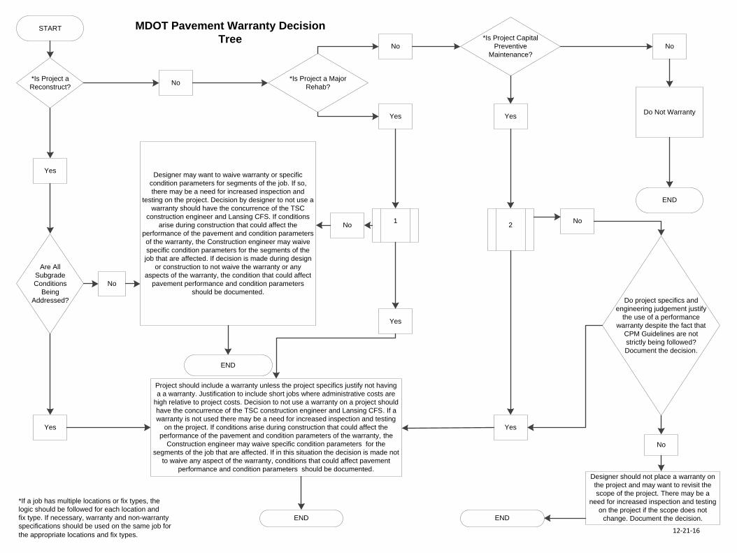
MDOT PAVEMENT WARRANTY DECISION TREE Historically, the decision on which MDOT projects included warranties was somewhat black and white. The decision was based mainly on type of fix and commercial Average Daily Traffic (ADT). As part of the warranty task force partnership between MDOT, FHWA, and industry; more detailed guidelines have been developed. The guidelines take into account scoping, design, and construction issues associated with different fix types to ensure the right warranty is placed on the right project. The following guidelines, in the form of a decision tree, were approved by the Engineering Operations Committee in December 2006.
START
Designer may want to waive warranty or specific
condition parameters for segments of the job. If so,
there may be a need for increased inspection and
testing on the project. Decision by designer to not use a
warranty should have the concurrence of the TSC
construction engineer and Lansing CFS. If conditions
arise during construction that could affect the
performance of the pavement and condition parameters
of the warranty, the Construction engineer may waive
specific condition parameters for the segments of the
job that are affected. If decision is made during design
or construction to not waive the warranty or any
aspects of the warranty, the condition that could affect
pavement performance and condition parameters
should be documented.
Project should include a warranty unless the project specifics justify not having
a a warranty. Justification to include short jobs where administrative costs are
high relative to project costs. Decision to not use a warranty on a project should
have the concurrence of the TSC construction engineer and Lansing CFS. If a
warranty is not used there may be a need for increased inspection and testing
on the project. If conditions arise during construction that could affect the
performance of the pavement and condition parameters of the warranty, the
Construction engineer may waive specific condition parameters for the
segments of the job that are affected. If in this situation the decision is made not
to waive any aspect of the warranty, conditions that could affect pavement
performance and condition parameters should be documented.
*Is Project a
Reconstruct?
Yes
Are All
Subgrade
Conditions
Being
Addressed?
No
END
Yes
END
No*Is Project a Major
Rehab?
Yes
1 No
Yes
No
Yes
*Is Project Capital
Preventive
Maintenance?
No
Do Not Warranty
END
2No
Do project specifics and
engineering judgement justify
the use of a performance
warranty despite the fact that
CPM Guidelines are not
strictly being followed?
Document the decision.
Yes
Designer should not place a warranty on
the project and may want to revisit the
scope of the project. There may be a
need for increased inspection and testing
on the project if the scope does not
change. Document the decision.
No
MDOT Pavement Warranty Decision
Tree
RETURN
END
1 2
RETURN
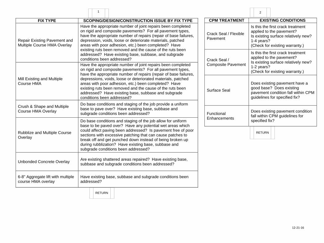
FIX TYPE SCOPING/DESIGN/CONSTRUCTION ISSUE BY FIX TYPE
Repair Existing Pavement and Multiple Course HMA Overlay
Have the appropriate number of joint repairs been completed on rigid and composite pavements? For all pavement types, have the appropriate number of repairs (repair of base failures, depression, voids, loose or deteriorate materials, patched areas with poor adhesion, etc.) been completed? Have existing ruts been removed and the cause of the ruts been addressed? Have existing base, subbase, and subgrade conditions been addressed?
Mill Existing and Multiple Course HMA
Have the appropriate number of joint repairs been completed on rigid and composite pavements? For all pavement types, have the appropriate number of repairs (repair of base failures, depressions, voids, loose or deteriorated materials, patched areas with poor adhesion, etc.) been completed? Have existing ruts been removed and the cause of the ruts been addressed? Have existing base, subbase and subgrade conditions been addressed?
Crush & Shape and Multiple Course HMA Overlay
Do base conditions and staging of the job provide a uniform base to pave over? Have existing base, subbase and subgrade conditions been addressed?
Rubblize and Multiple Course Overlay
Do base conditions and staging of the job allow for uniform base to be paved over? Have any potential wet areas which could affect paving been addressed? Is pavement free of poor sections with excessive patching that can cause patches to break off and get punched down instead of being broken up during rubblization? Have existing base, subbase and subgrade conditions been addressed?
Unbonded Concrete Overlay Are existing shattered areas repaired? Have existing base, subbase and subgrade conditions been addressed?
6-8" Aggregate lift with multiple course HMA overlay
Have existing base, subbase and subgrade conditions been addressed?
CPM TREATMENT EXISTING CONDITIONS
Crack Seal / Flexible Pavement
Is this the first crack treatment applied to the pavement? Is existing surface relatively new? 1-4 years? (Check for existing warranty.)
Crack Seal / Composite Pavement
Is this the first crack treatment applied to the pavement? Is existing surface relatively new? 1-2 years? (Check for existing warranty.)
Surface Seal
Does existing pavement have a good base? Does existing pavement condition fall within CPM guidelines for specified fix?
Functional Enhancements
Does existing pavement condition fall within CPM guidelines for specified fix?
12-21-16
12-21-16
*If a job has multiple locations or fix types, the
logic should be followed for each location and
fix type. If necessary, warranty and non-warranty
specifications should be used on the same job for
the appropriate locations and fix types.
START
Designer may want to waive warranty or specific
condition parameters for segments of the job. If so,
there may be a need for increased inspection and
testing on the project. Decision by designer to not use a
warranty should have the concurrence of the TSC
construction engineer and Lansing CFS. If conditions
arise during construction that could affect the
performance of the pavement and condition parameters
of the warranty, the Construction engineer may waive
specific condition parameters for the segments of the
job that are affected. If decision is made during design
or construction to not waive the warranty or any
aspects of the warranty, the condition that could affect
pavement performance and condition parameters
should be documented.
Project should include a warranty unless the project specifics justify not having
a a warranty. Justification to include short jobs where administrative costs are
high relative to project costs. Decision to not use a warranty on a project should
have the concurrence of the TSC construction engineer and Lansing CFS. If a
warranty is not used there may be a need for increased inspection and testing
on the project. If conditions arise during construction that could affect the
performance of the pavement and condition parameters of the warranty, the
Construction engineer may waive specific condition parameters for the
segments of the job that are affected. If in this situation the decision is made not
to waive any aspect of the warranty, conditions that could affect pavement
performance and condition parameters should be documented.
*Is Project a
Reconstruct?
Yes
Are All
Subgrade
Conditions
Being
Addressed?
No
END
Yes
END
No*Is Project a Major
Rehab?
Yes
1 No
Yes
No
Yes
*Is Project Capital
Preventive
Maintenance?
No
Do Not Warranty
END
2No
Do project specifics and
engineering judgement justify
the use of a performance
warranty despite the fact that
CPM Guidelines are not
strictly being followed?
Document the decision.
Yes
Designer should not place a warranty on
the project and may want to revisit the
scope of the project. There may be a
need for increased inspection and testing
on the project if the scope does not
change. Document the decision.
No
MDOT Pavement Warranty Decision
Tree
RETURN
END
1 2
RETURN
FIX TYPE SCOPING/DESIGN/CONSTRUCTION ISSUE BY FIX TYPE
Repair Existing Pavement and Multiple Course HMA Overlay
Have the appropriate number of joint repairs been completed on rigid and composite pavements? For all pavement types, have the appropriate number of repairs (repair of base failures, depression, voids, loose or deteriorate materials, patched areas with poor adhesion, etc.) been completed? Have existing ruts been removed and the cause of the ruts been addressed? Have existing base, subbase, and subgrade conditions been addressed?
Mill Existing and Multiple Course HMA
Have the appropriate number of joint repairs been completed on rigid and composite pavements? For all pavement types, have the appropriate number of repairs (repair of base failures, depressions, voids, loose or deteriorated materials, patched areas with poor adhesion, etc.) been completed? Have existing ruts been removed and the cause of the ruts been addressed? Have existing base, subbase and subgrade conditions been addressed?
Crush & Shape and Multiple Course HMA Overlay
Do base conditions and staging of the job provide a uniform base to pave over? Have existing base, subbase and subgrade conditions been addressed?
Rubblize and Multiple Course Overlay
Do base conditions and staging of the job allow for uniform base to be paved over? Have any potential wet areas which could affect paving been addressed? Is pavement free of poor sections with excessive patching that can cause patches to break off and get punched down instead of being broken up during rubblization? Have existing base, subbase and subgrade conditions been addressed?
Unbonded Concrete Overlay Are existing shattered areas repaired? Have existing base, subbase and subgrade conditions been addressed?
6-8" Aggregate lift with multiple course HMA overlay
Have existing base, subbase and subgrade conditions been addressed?
CPM TREATMENT EXISTING CONDITIONS
Crack Seal / Flexible Pavement
Is this the first crack treatment applied to the pavement? Is existing surface relatively new? 1-4 years? (Check for existing warranty.)
Crack Seal / Composite Pavement
Is this the first crack treatment applied to the pavement? Is existing surface relatively new? 1-2 years? (Check for existing warranty.)
Surface Seal
Does existing pavement have a good base? Does existing pavement condition fall within CPM guidelines for specified fix?
Functional Enhancements
Does existing pavement condition fall within CPM guidelines for specified fix?
12-21-16
12-21-16
*If a job has multiple locations or fix types, the
logic should be followed for each location and
fix type. If necessary, warranty and non-warranty
specifications should be used on the same job for
the appropriate locations and fix types.
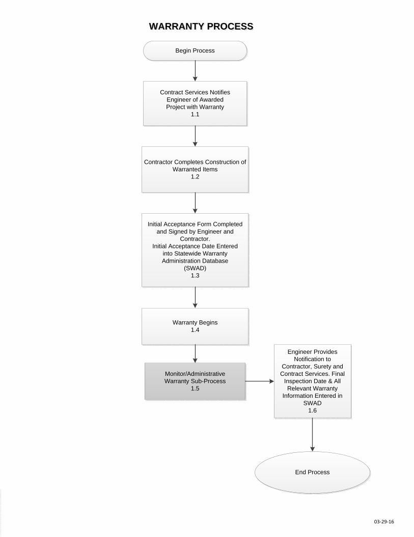
Contract Services NotifiesEngineer of AwardedProject with Warranty
1.1
Contractor Completes Construction of Warranted Items
1.2
Initial Acceptance Form Completed and Signed by Engineer and
Contractor.Initial Acceptance Date Entered
into Statewide Warranty Administration Database
(SWAD) 1.3
Warranty Begins1.4
Monitor/AdministrativeWarranty Sub-Process
1.5
Engineer Provides Notification to
Contractor, Surety andContract Services. Final
Inspection Date & AllRelevant Warranty
Information Entered in SWAD
1.6
End Process
WARRANTY PROCESS
Begin Process
03-29-16
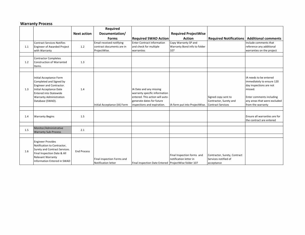
Warranty Process
Next actionRequired
Documentation/ Forms Required SWAD Action
Required ProjectWise Action Required Notifications Additional comments
1.1
Contract Services Notifies Engineer of Awarded Project with Warranty
1.2
Email received notifying contract documents are in ProjectWise.
Enter Contract information and check for multiple warranties
Copy Warranty SP and Warranty Bond info to folder 107
Include comments that reference any additional warranties on the project
1.2
Contractor Completes Construction of Warranted Items.
1.3
1.3
Initial Acceptance Form Completed and Signed by Engineer and Contractor. Initial Acceptance Date Entered into Statewide Warranty Administration Database (SWAD).
1.4
Initial Acceptance (IA) Form
IA Date and any missing warranty specific information entered. This action will auto‐generate dates for future inspections and expiration. IA form put into ProjectWise.
Signed copy sent to Contractor, Surety and Contract Services
IA needs to be entered immediately to ensure 120 day inspections are not missed.
Enter comments including any areas that were excluded from the warranty
1.4 Warranty Begins 1.5 Ensure all warranties are for the contract are entered
1.5Monitor/Administrative Warranty Sub‐Process
2.1
1.6
Engineer Provides Notification to Contractor, Surety and Contract Services. Final Inspection Date & All Relevant Warranty Information Entered in SWAD
End Process
Final inspection Forms and
Notification letter Final inspection Date Entered
Final Inspection forms and notification letter in ProjectWise folder 107
Contractor, Surety, Contract Services notified of acceptance
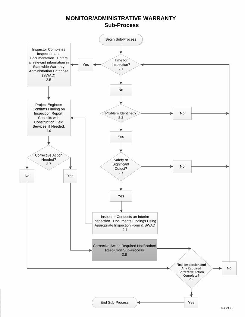
MONITOR/ADMINISTRATIVE WARRANTYSub-Process
Begin Sub-Process
Time forInspection?
2.1Yes
Inspector Completes Inspection and
Documentation. Enters all relevant information in
Statewide Warranty Administration Database
(SWAD)2.5
No
Problem Identified?2.2
Yes
Safety orSignificant
Defect?2.3
Yes
Inspector Conducts an Interim Inspection. Documents Findings UsingAppropriate Inspection Form & SWAD
2.4
Corrective Action Required Notification/Resolution Sub-Process
2.8
End Sub-Process
Project EngineerConfirms Finding on Inspection Report.
Consults with Construction Field
Services, if Needed.2.6
Corrective Action Needed?
2.7
YesNo
No
03-29-16
Final Inspection and Any Required
Corrective Action Complete?
2.9
Yes
No
No
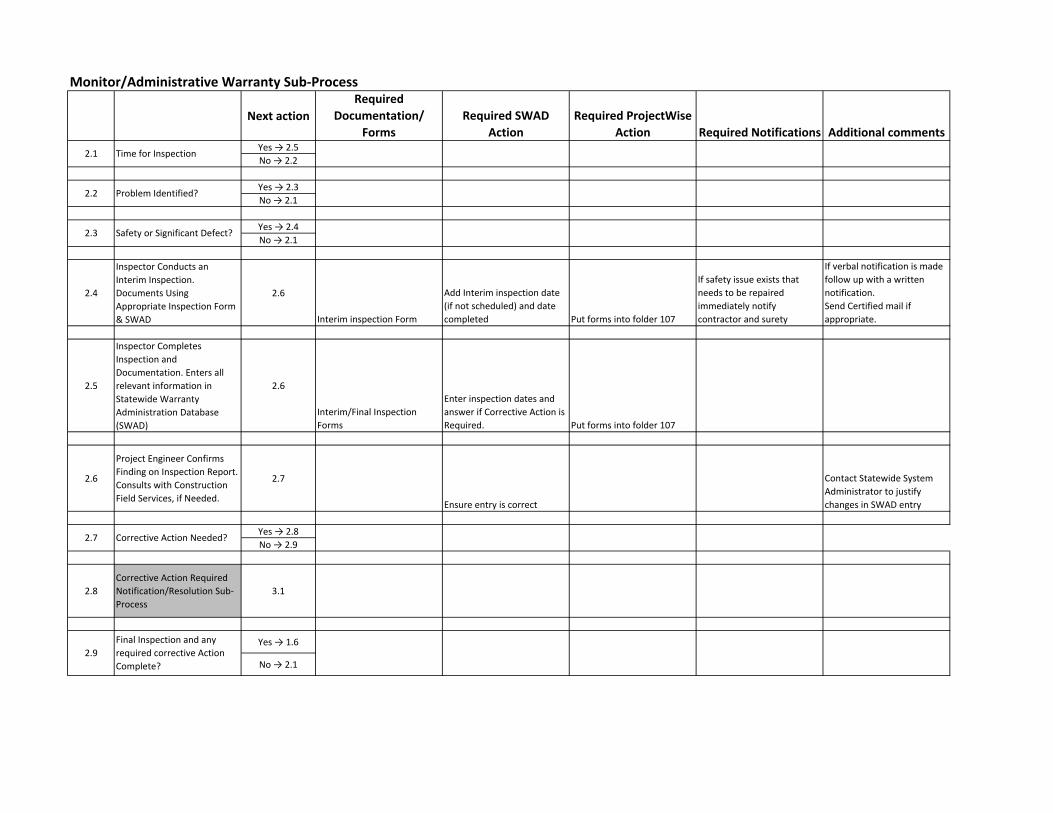
Monitor/Administrative Warranty Sub‐Process
Next actionRequired
Documentation/ Forms
Required SWAD Action
Required ProjectWise Action Required Notifications Additional comments
Yes → 2.5
No → 2.2
Yes → 2.3
No → 2.1
Yes → 2.4
No → 2.1
2.4
Inspector Conducts an Interim Inspection. Documents Using Appropriate Inspection Form & SWAD
2.6
Interim inspection Form
Add Interim inspection date (if not scheduled) and date completed Put forms into folder 107
If safety issue exists that needs to be repaired immediately notify contractor and surety
If verbal notification is made follow up with a written notification. Send Certified mail if appropriate.
2.5
Inspector Completes Inspection and Documentation. Enters all relevant information in Statewide Warranty Administration Database (SWAD)
2.6
Interim/Final Inspection Forms
Enter inspection dates and answer if Corrective Action is Required. Put forms into folder 107
2.6
Project Engineer Confirms Finding on Inspection Report. Consults with Construction Field Services, if Needed.
2.7
Ensure entry is correct
Contact Statewide System Administrator to justify changes in SWAD entry
Yes → 2.8
No → 2.9
2.8
Corrective Action Required Notification/Resolution Sub‐Process
3.1
Yes → 1.6
No → 2.1
Time for Inspection
Problem Identified?
Safety or Significant Defect?
Corrective Action Needed?
2.1
2.2
2.3
2.7
2.9
Final Inspection and any required corrective Action Complete?
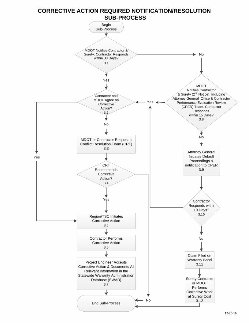
CORRECTIVE ACTION REQUIRED NOTIFICATION/RESOLUTION
SUB-PROCESSBegin
Sub-Process
Contractor and
MDOT Agree on
Corrective
Action?
3.2
MDOT or Contractor Request a
Conflict Resolution Team (CRT)
3.3
CRT
Recommends
Corrective
Action?
3.4
Region/TSC Initiates
Corrective Action
3.5
Contractor Performs
Corrective Action
3.6
Project Engineer Accepts
Corrective Action & Documents All
Relevant Information in the
Statewide Warranty Administration
Database (SWAD)
3.7
End Sub-Process
MDOT
Notifies Contractor
& Surety (2nd
Notice). Including
Attorney General Office & Contractor
Performance Evaluation Review
(CPER) Team. Contractor
Responds
within 15 Days?
3.8
MDOT Notifies Contractor & Surety. Contractor Responds
within 30 Days?
3.1
Attorney General
Initiates Default
Proceedings &
notification to CPER
3.9
Contractor
Responds within
10 Days?
3.10
Claim Filed on
Warranty Bond
3.11
Surety Contracts
or MDOT
Performs
Corrective Work
at Surety Cost
3.12
12-20-16
Yes
No
Yes
Yes
No
No
No
Yes
No
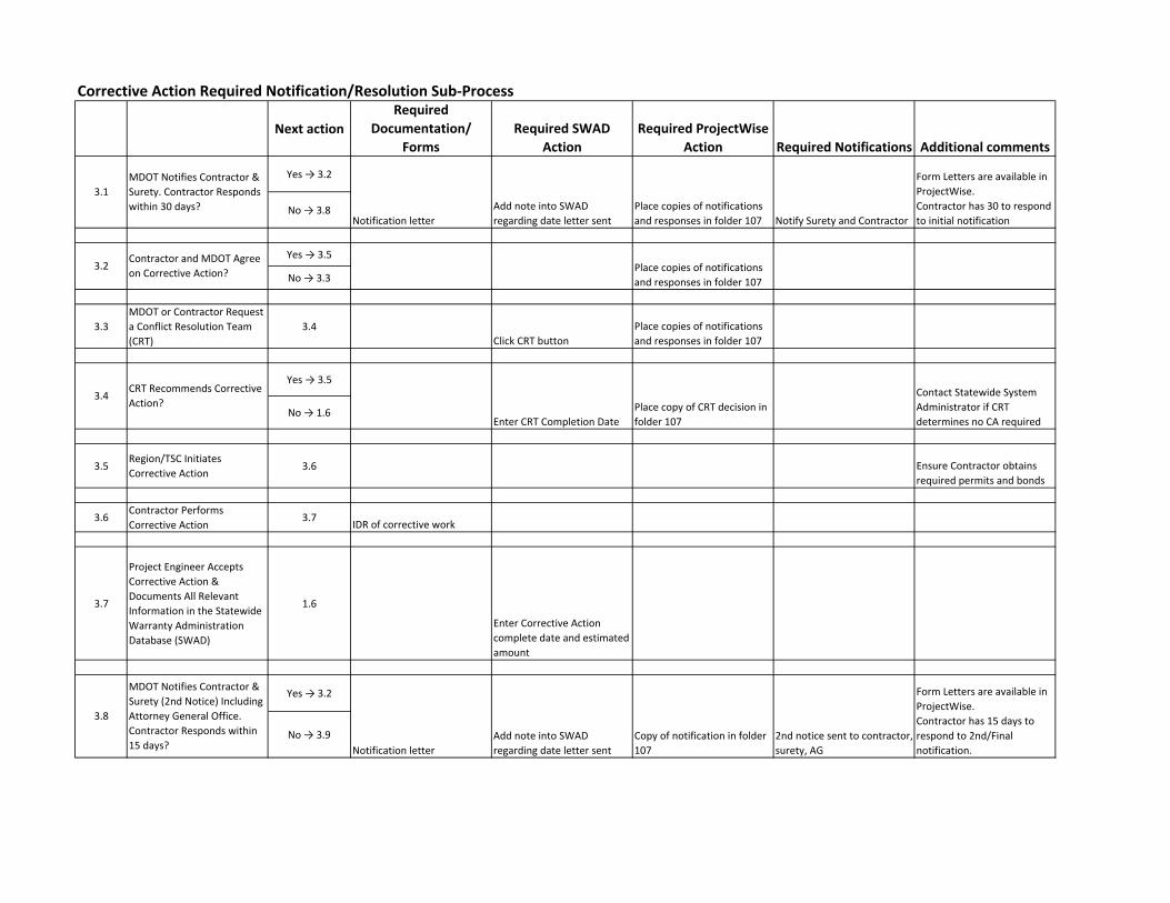
Corrective Action Required Notification/Resolution Sub‐Process
Next actionRequired
Documentation/ Forms
Required SWAD Action
Required ProjectWise Action Required Notifications Additional comments
Yes → 3.2
No → 3.8
Yes → 3.5
No → 3.3
3.3
MDOT or Contractor Request a Conflict Resolution Team (CRT)
3.4
Click CRT button
Place copies of notifications and responses in folder 107
Yes → 3.5
No → 1.6
3.5Region/TSC Initiates Corrective Action
3.6 Ensure Contractor obtains required permits and bonds
3.6Contractor Performs Corrective Action
3.7IDR of corrective work
3.7
Project Engineer Accepts Corrective Action & Documents All Relevant Information in the Statewide Warranty Administration Database (SWAD)
1.6
Enter Corrective Action complete date and estimated amount
Yes → 3.2
No → 3.9
MDOT Notifies Contractor & Surety. Contractor Responds within 30 days?
Contractor and MDOT Agree on Corrective Action?
CRT Recommends Corrective Action?
MDOT Notifies Contractor & Surety (2nd Notice) Including Attorney General Office. Contractor Responds within 15 days?
3.1
3.2
3.4
3.8
Notification letter
Add note into SWAD regarding date letter sent
Place copies of notifications and responses in folder 107 Notify Surety and Contractor
Form Letters are available in ProjectWise. Contractor has 30 to respond to initial notification
Place copies of notifications and responses in folder 107
Enter CRT Completion Date
Place copy of CRT decision in folder 107
Contact Statewide System Administrator if CRT determines no CA required
Notification letter
Add note into SWAD regarding date letter sent
Copy of notification in folder 107
2nd notice sent to contractor, surety, AG
Form Letters are available in ProjectWise. Contractor has 15 days to respond to 2nd/Final notification.
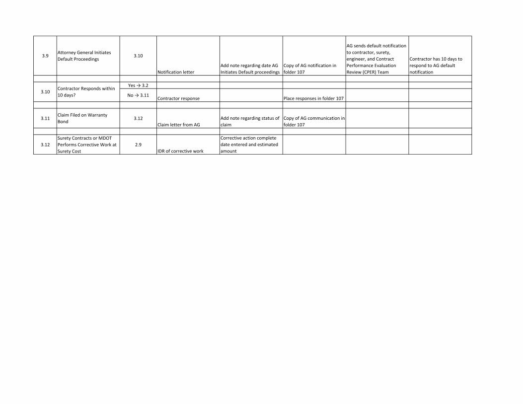
3.9Attorney General Initiates Default Proceedings
3.10
Notification letter
Add note regarding date AG Initiates Default proceedings
Copy of AG notification in folder 107
AG sends default notification to contractor, surety, engineer, and Contract Performance Evaluation Review (CPER) Team
Contractor has 10 days to respond to AG default notification
Yes → 3.2
No → 3.11Contractor response Place responses in folder 107
3.11Claim Filed on Warranty Bond
3.12
Claim letter from AG
Add note regarding status of claim
Copy of AG communication in folder 107
3.12
Surety Contracts or MDOT Performs Corrective Work at Surety Cost
2.9
IDR of corrective work
Corrective action complete date entered and estimated amount
Contractor Responds within 10 days?
3.10
WARRANTY INSPECTION GUIDELINES HMA CRACK TREATMENT
Use With 03SP505(A) Pavement Performance Warranty for HMA Crack Treatment (Capital
Preventive Maintenance) 12SP502(A) Warranty Work Requirements for Hot Mix Asphalt Crack Treatment (Capital Preventive Maintenance) Form 1047 CPM - H.M.A. Crack Treatment - Cursory Inspection Form 1046 CPM - H.M.A. Crack Treatment - Detailed Inspection
These HMA Crack Treatment Warranty Guidelines do not apply to locations treated under stand-alone overband crackfill special provisions.
Warranty 24 months Duration Inspection 20 months after Initial Acceptance Period Begins Notes An evaluation segment is defined as a 528 foot length of driving lane. The
beginning point for laying out segments will be the Point of Beginning (POB) of the project. Segments will be laid out consecutively to the Point of Ending (POE) of the project.
Driving Lane(s) are the delineated pavement surface used by traffic. Each of the following is considered a separate driving lane: - Each individual mainline lane - The sum of all ramp lanes and associated acceleration/deceleration lanes - The sum of all auxiliary lanes, such as passing lanes and turn lanes.
The threshold level is reviewed separately for each crack treatment work type.
A location is defined as a continuous section of roadbed (or roadbeds on a divided highway) for which beginning and ending points are defined within the contract documentation.
Working cracks are cracks that experience 1/8th inch or more of horizontal vertical movement as a result of temperature change or traffic loading.
Non-working cracks are cracks that experience less than 1/8th inch of horizontal or vertical movement as a result of temperature change or traffic loading.
Procedure Perform Warranty Acceptance Inspection
Based on results of the inspection, recommend the project for either:
1. Final Acceptance - No warranty work required; inspection complete or
2. Warranty Work - Provide the Contractor with results of the inspection indicating areas where warranty work is required.
If conflict resolution process is initiated then:
Perform Detailed Warranty Acceptance Inspection (if required) Based on results of the detailed inspection, either: 1. Warranty Work is Required and Verified - Provide the Contractor with results
of the inspection indicating areas where warranty work is required. or
2. Recommend Final Acceptance - No warranty work required Condition Parameter Measurement Adhesion and/or cohesion are the performance parameters monitored to assess the integrity of the crack treatment. Failure is defined as areas along the sealed or filled crack exhibiting loss of adhesion (loss of crack seal material from the crack reservoir or crack seal pulling away from the sidewalls of the reservoir) or lack of cohesiveness (splitting) within the crack seal material. Cursory Warranty Inspection for HMA Crack Treatment The objective of the cursory inspection is to identify evaluation segments of crack treatment failure for each work location and to document the condition prior to warranty expiration. It is recommended that inspectors consider areas that exhibit the highest level of failure when selecting evaluation segments. All working cracks in traveled lanes are required to be sealed by the Saw/Rout and Seal Method. Non-working cracks in the traveled lanes and in shoulder areas may be filled by either method, although the Overband Crack Fill method is more commonly used for longitudinal joints and shoulder areas. A detailed description that explains how working and non-working cracks are determined within each project location is provided by the Contractor prior to the start of construction as part of the project quality control plan and can be found in the project construction files. A separate assessment of failure for each crack treatment work type (Saw/Rout and Seal Method and Overband Crack Fill Method) is required. Once the evaluation segments have been identified, the percent failure is estimated by visual inspection. The percent failure for each evaluation segment is estimated and compared to the failure threshold to determine if warranty work is required. All information is recorded on the HMA Crack Treatment Warranty Inspection form. Cursory Warranty Inspection Procedure 1. Lay out 528 foot segments starting at the POB of the project. Number the segments
consecutively from the POB to the POE of the project. This original segment layout will be used for all successive reviews of the project throughout the warranty period.
2. Perform a windshield survey of the entire location. Identify areas that exhibit the highest
concentration of adhesion and/or cohesion failures for each crack treatment work type within the location.
3. Record the segment and lane numbers for each questionable area.
4. Considering the results of the initial windshield survey, select the segments to be included in the warranty evaluation. A minimum of one segment per roadbed mile is evaluated for each project location. At least one segment must be evaluated for locations less than one roadbed mile in length. For a divided highway, a minimum of one segment in each direction per mile is evaluated. Additional segments in excess of the number required may also be evaluated.
5. Estimate and record the percent failure within each segment evaluated. A separate
assessment of failure for each crack treatment work type (Saw/Rout and Seal Method and Overband Crack Fill Method) is required.
6. Total the percent failures for all evaluation segments within each crack treatment work type
and divide this total percent failure by the total number of evaluation segments to determine the average percent failure for the location.
7. Determine if any of the following threshold conditions is exceeded for either work type:
a. Failure rate of any one segment is 30% or greater
b. Average failure rate of all segments is 10% or greater
If any of the above is true: Warranty Work is Required (within the failure work type)
If all of the above are false: Recommend Final Acceptance Detailed Warranty Inspection A more detailed inspection may be required if the Contractor contests the findings of the cursory warranty inspection and requests resolution in accordance with the conflict resolution procedures outlined in the Special Provision for Warranty Work Requirements for HMA Crack Treatment (Capital Preventive Maintenance). The objective of this inspection is to measure the total length of crack treatment and length of crack treatment failure within the segments evaluated in the cursory inspection. The actual percent failure for each segment and the total percent failure for each crack treatment work type is calculated based on actual measurements. Traffic control will most likely be required to complete the detailed inspection. Detailed Warranty Inspection Procedure: 1. Prior to starting the inspection, obtain existing lane and/or shoulder width information and note
the limits of varying pavement widths to facilitate crack length estimating and measurement operations.
2. Obtain information on evaluation segments from the previous cursory warranty inspection
form. Record the appropriate information on the detailed warranty inspection form. 3. Determine the method and approach to be used in obtaining crack length estimates and
measurements. Mark the POB and POE for each evaluation segment. Set up traffic control where appropriate.
4. Approximate and/or measure and record the length of seal failure and the total length of cracks
treated within each evaluation segment. A separate assessment of failure for each crack
treatment work type (Saw/Rout and Seal Method and Overband Crack Fill Method) is required. Crack lengths can be approximated through a combination of methods including direct measurement, crack counts, estimating crack lengths by comparison to lane or shoulder widths and through use of data from the Department’s Pavement Management System.
5. Calculate and record the percent failure for each evaluation segment according to the following
formula: (Length of Failure / Total Length of Cracks) x 100 = Percent Failure
6. Total the percent failures for all evaluation segments within each crack treatment work type
and divide this total percent failure by the total number of evaluation segments to determine the average percent failure for the location,.
7. Decide if any of the following threshold conditions is exceeded for either work type:
a. Failure rate of any one evaluation segment is 30% or greater
b. Average failure rate of all evaluation segments is 10% or greater
If any of the above is true: Warranty Work is Required and Verified (within the failure work type)
If all of the above are false: Recommend Final Acceptance
WARRANTY INSPECTION GUIDELINES HMA OVERLAY - CPM
Use With 03SP502(W) Material and Workmanship Pavement Warranty Cold Milling and One Course Hot Mix Asphalt Overlay 03SP502(X) Material and Workmanship Pavement Warranty One Course Hot Mix Asphalt Overlay 12SP501(R) Warranty Work Requirements for Cold Milling and One Course Hot Mix Asphalt (HMA) Overlay (Capital Preventive Maintenance) 12SP501(S) Warranty Work Requirements for One Course Hot Mix Asphalt (HMA) Overlay (Capital Preventive Maintenance) Form 1184 CPM - HMA Overlay & Coldmilling and HMA Overlay (Cursory Inspection) Form 1193A-E CPM - HMA Overlay & Coldmilling and HMA Overlay (Detailed Inspection)
Warranty 36 months Duration Inspection 32 months after Initial Acceptance Period Begins Notes Segments are defined as 528 foot lengths of a driving lane.
The starting point of a segment is the start of any individual distress type.
The threshold level for each distress type is determined separately. Procedure Perform Cursory Warranty Acceptance Inspection.
Based on results of the cursory inspection, recommend the project for either:
1. Final Acceptance - No warranty work required; Inspection complete or
2. Detailed Inspection - More detailed inspection and measurements required
Perform Detailed Warranty Acceptance Inspection if required Based on results of the detailed inspection, either:
1. Recommend Final Acceptance - No warranty work required
or 2. Warranty Work is Required and Verified - Provide the Contractor with results
of the inspection indicating areas where warranty work is required. Condition Parameter Measurement Performance parameters will be measured as described for each of the following distress types. 1. Longitudinal Cracking - Total linear feet of longitudinal cracks in a segment. Only count
cracks that are not “reflective” from a prior crack or joint. Count all longitudinal cracks that cannot be positively identified as “reflective” or are questionable. Each individual crack must exceed 5 feet in length to be included in the total.
2. De-bonding- Total longitudinal length, in feet, of de-bonding in a segment. Measure
individual de-bonding locations in the longitudinal direction, regardless of the width of the distress location. Potholes are classified as de-bonding.
3. Raveling - Total area, in square feet, of raveling in a segment. Measure individual raveling
areas and sum the areas for the segment. 4. Flushing - Total area, in square feet, of flushing in a segment. Measure individual flushed
areas and sum the areas for the segment. 5. Rutting - The average rut depth, in inches, in a segment. Measure the rut depth in both wheel
paths at 65', 197', 328', and 460' from the segment POB. Record only the largest (deepest) of the two wheel path measurements at each interval. The average of these four measurements is the average rut depth of the segment.
Cursory Warranty Inspection for HMA Overlay The purpose of this inspection is to rule out the possibility that warranty work is required. If the “worst segments” of the project appear to be below distress threshold limits, no warranty work is required and the project can be accepted. If it appears that one or more distress threshold limits may be exceeded, a Detailed Inspection is required. Cursory Inspection Procedure: Form 1184 1. Perform a “windshield” survey of the entire location length. Based solely on visual
examination and estimated measurements, approximate the individual distress quantities for the “worst” segment(s) of each distress type and record on the Cursory Inspection Form:
2. Determine if any of the following distress threshold conditions are exceeded.
(*Based on lane width = 12')
a. Longitudinal Cracking exceeds 25% of the segment length (132' within 528'*) for any 4 segments.
b. Delamination exceeds 25% of the segment length (132' within 528' *) for any 4
segments.
c. Raveling exceeds 20% of the segment length (105.6' within 528' *) for any 2 segments.
d. Flushing exceeds 5% of the segment length (26.4' within 528' *) for any 2 segments.
e. Average rut depth exceeds .25 inches for any 1 segment. 3. If any condition above is true:
a. Perform Detailed Inspection; and
b. Provide a description of the magnitude and location(s) of the distress condition(s) observed which justify the Detailed Inspection.
4. If all conditions above are false, recommend final acceptance.
Detailed Inspection for HMA Overlay The purpose of this inspection is to accurately measure and document the amount of pavement distress to determine if the project meets the terms of the warranty and to determine what actions, if any, will be required by the Contractor. This inspection provides the documentation the Department needs to enforce the warranty specifications. Detailed Inspection Procedure: Forms 1193A-E 1. Determine the worst segments (exceeding threshold limits) for each individual distress type.
2. Document the lane, direction, and distance from POB, of each questionable segment identified
in Step 1.
3. For each questionable segment, measure and record the amount of each individual distress type and record on the appropriate inspection form.
a. Longitudinal Cracking - Form 1193A
b. De-bonding- Form 1193B
c. Raveling - Form 1193C
d. Flushing - Form 1193D
e. Rutting - Form 1193E
4. Determine if any of the threshold limits for longitudinal cracking, de-bonding, raveling or flushing, listed under Cursory Inspection, are exceeded.
5. Evaluate segments where the average rut depth appears to exceed .25 inches as follows.
a. Measure the average rutting at all questionable segments to verify that the threshold was exceeded.
b. Request pavement cores and analysis for those segments found to exceed the average
rutting threshold limits. A minimum of one pavement core must be requested for each contiguous group of segments that exceed the threshold limits. Determine by analysis if those segments were not produced in accordance with the job mix formula (JMF). Both of these conditions must exist to trigger warranty work due to rutting.
6. Warranty work is required at those segments for which any of the threshold limits for
longitudinal cracking, delamination, raveling or flushing are exceeded and/or where the average rut depth exceeds .25 inches and analysis shows the JMF was not followed. Provide the Contractor with results of the inspection indication segments where warranty work is required.
WARRANTY INSPECTION GUIDELINES MICRO-SURFACING - CPM
Use With 03SP507(A) Pavement Performance Warranty for Micro-Surfacing (Capital
Preventive Maintenance) 12SP504(A) Warranty Work Requirements for Micro-Surfacing (Capital Preventive Maintenance) Form 1893 CPM - Micro surfacing (Cursory Inspection) Form 1894 CPM - Micro surfacing (Detailed Inspection - incl. worksheet)
Warranty 24 months Duration Inspection 20 months after Initial Acceptance Period Begins Notes Segments are defined as 528 foot lengths of a driving lane.
The threshold level for each distress type is determined separately. Procedure: Perform Cursory Inspection.
Based on results of Cursory Inspection, recommend the project for either:
1. Final Acceptance - No warranty work required; inspection complete or
2. Detailed Inspection - Perform detailed inspection
Perform Detailed Inspection if Required. Based on results of the detailed inspection, either:
1. Recommend Final Acceptance - No warranty work required
or 2. Warranty Work is Required and Verified - Provide the Contractor with results
of the inspection indicating areas where warranty work is required. Condition Parameter Measurement Performance parameters shall be measured as described for each distress type. 1. Debonding - Total linear feet of debonding in a segment. Measure individual debonding
locations in the longitudinal direction, regardless of the width of the distress location, and sum the lengths for each segment. Potholes will be classified as debonding.
2. Raveling - Total longitudinal feet of raveling in a segment. Measure individual raveling
locations in the longitudinal direction, regardless of the width of the distress location, and sum the lengths for each segment.
3. Bleeding/Flushing - Total longitudinal feet of flushing in a segment. Measure individual
flushed locations in the longitudinal direction, regardless of the width of the distress location, and sum the lengths for each segment.
4. Average rut depth - Measure the rut depth for each wheel path independently at 65', 200', 330', 460'. The average of these four measurements is the average rut depth for the right or left wheel path. Use only the largest (deepest) average rut depth when evaluating the segment with the threshold value.
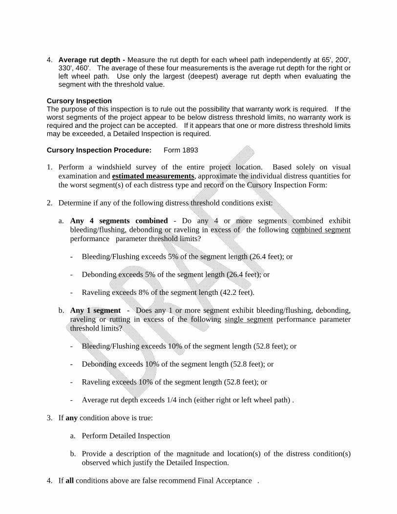
Cursory Inspection The purpose of this inspection is to rule out the possibility that warranty work is required. If the worst segments of the project appear to be below distress threshold limits, no warranty work is required and the project can be accepted. If it appears that one or more distress threshold limits may be exceeded, a Detailed Inspection is required. Cursory Inspection Procedure: Form 1893 1. Perform a windshield survey of the entire project location. Based solely on visual
examination and estimated measurements, approximate the individual distress quantities for the worst segment(s) of each distress type and record on the Cursory Inspection Form:
2. Determine if any of the following distress threshold conditions exist:
a. Any 4 segments combined - Do any 4 or more segments combined exhibit bleeding/flushing, debonding or raveling in excess of the following combined segment performance parameter threshold limits?
- Bleeding/Flushing exceeds 5% of the segment length (26.4 feet); or
- Debonding exceeds 5% of the segment length (26.4 feet); or
- Raveling exceeds 8% of the segment length (42.2 feet).
b. Any 1 segment - Does any 1 or more segment exhibit bleeding/flushing, debonding,
raveling or rutting in excess of the following single segment performance parameter threshold limits?
- Bleeding/Flushing exceeds 10% of the segment length (52.8 feet); or
- Debonding exceeds 10% of the segment length (52.8 feet); or
- Raveling exceeds 10% of the segment length (52.8 feet); or
- Average rut depth exceeds 1/4 inch (either right or left wheel path) .
3. If any condition above is true:
a. Perform Detailed Inspection
b. Provide a description of the magnitude and location(s) of the distress condition(s) observed which justify the Detailed Inspection.
4. If all conditions above are false recommend Final Acceptance .
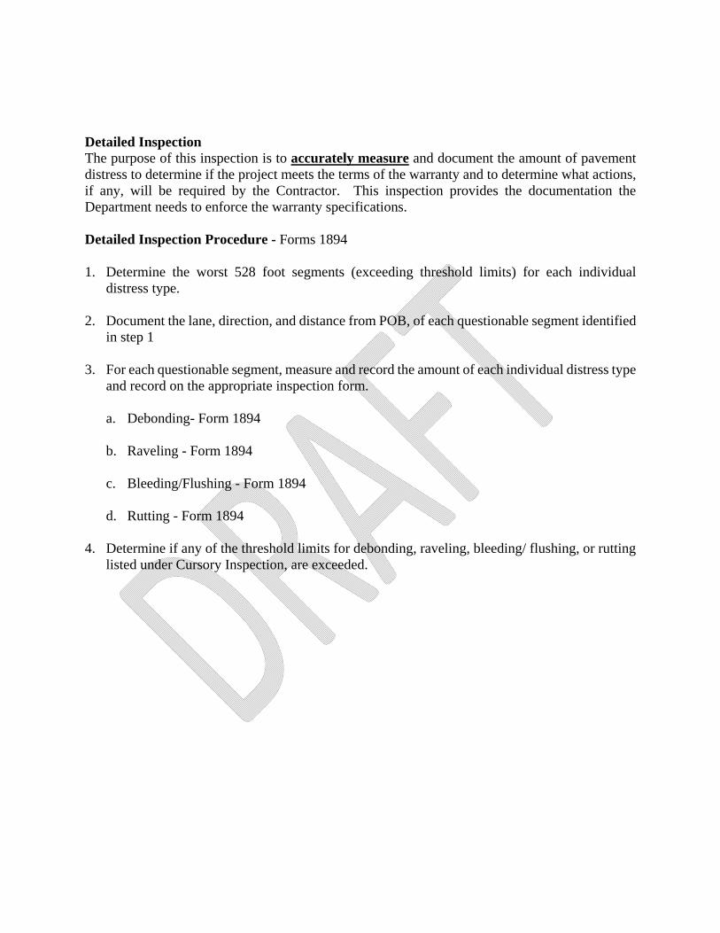
Detailed Inspection The purpose of this inspection is to accurately measure and document the amount of pavement distress to determine if the project meets the terms of the warranty and to determine what actions, if any, will be required by the Contractor. This inspection provides the documentation the Department needs to enforce the warranty specifications. Detailed Inspection Procedure - Forms 1894 1. Determine the worst 528 foot segments (exceeding threshold limits) for each individual
distress type.
2. Document the lane, direction, and distance from POB, of each questionable segment identified in step 1
3. For each questionable segment, measure and record the amount of each individual distress type and record on the appropriate inspection form.
a. Debonding- Form 1894
b. Raveling - Form 1894
c. Bleeding/Flushing - Form 1894
d. Rutting - Form 1894
4. Determine if any of the threshold limits for debonding, raveling, bleeding/ flushing, or rutting
listed under Cursory Inspection, are exceeded.
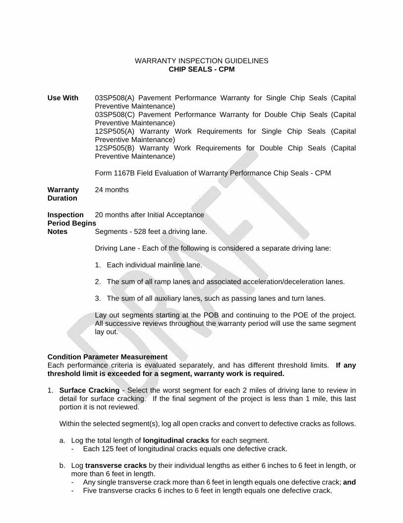
WARRANTY INSPECTION GUIDELINES CHIP SEALS - CPM
Use With 03SP508(A) Pavement Performance Warranty for Single Chip Seals (Capital
Preventive Maintenance) 03SP508(C) Pavement Performance Warranty for Double Chip Seals (Capital
Preventive Maintenance) 12SP505(A) Warranty Work Requirements for Single Chip Seals (Capital Preventive Maintenance) 12SP505(B) Warranty Work Requirements for Double Chip Seals (Capital Preventive Maintenance)
Form 1167B Field Evaluation of Warranty Performance Chip Seals - CPM
Warranty 24 months Duration Inspection 20 months after Initial Acceptance Period Begins Notes Segments - 528 feet a driving lane.
Driving Lane - Each of the following is considered a separate driving lane:
1. Each individual mainline lane.
2. The sum of all ramp lanes and associated acceleration/deceleration lanes.
3. The sum of all auxiliary lanes, such as passing lanes and turn lanes.
Lay out segments starting at the POB and continuing to the POE of the project. All successive reviews throughout the warranty period will use the same segment lay out.
Condition Parameter Measurement Each performance criteria is evaluated separately, and has different threshold limits. If any threshold limit is exceeded for a segment, warranty work is required. 1. Surface Cracking - Select the worst segment for each 2 miles of driving lane to review in
detail for surface cracking. If the final segment of the project is less than 1 mile, this last portion it is not reviewed.
Within the selected segment(s), log all open cracks and convert to defective cracks as follows.
a. Log the total length of longitudinal cracks for each segment.
- Each 125 feet of longitudinal cracks equals one defective crack. b. Log transverse cracks by their individual lengths as either 6 inches to 6 feet in length, or
more than 6 feet in length. - Any single transverse crack more than 6 feet in length equals one defective crack; and - Five transverse cracks 6 inches to 6 feet in length equals one defective crack.
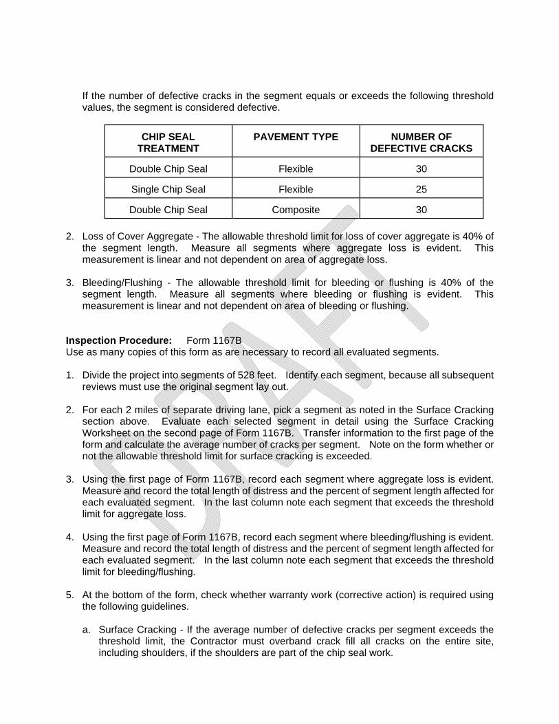
If the number of defective cracks in the segment equals or exceeds the following threshold values, the segment is considered defective.
CHIP SEAL TREATMENT
PAVEMENT TYPE NUMBER OF DEFECTIVE CRACKS
Double Chip Seal Flexible 30
Single Chip Seal Flexible 25
Double Chip Seal Composite 30
2. Loss of Cover Aggregate - The allowable threshold limit for loss of cover aggregate is 40% of
the segment length. Measure all segments where aggregate loss is evident. This measurement is linear and not dependent on area of aggregate loss.
3. Bleeding/Flushing - The allowable threshold limit for bleeding or flushing is 40% of the
segment length. Measure all segments where bleeding or flushing is evident. This measurement is linear and not dependent on area of bleeding or flushing.
Inspection Procedure: Form 1167B Use as many copies of this form as are necessary to record all evaluated segments. 1. Divide the project into segments of 528 feet. Identify each segment, because all subsequent
reviews must use the original segment lay out.
2. For each 2 miles of separate driving lane, pick a segment as noted in the Surface Cracking section above. Evaluate each selected segment in detail using the Surface Cracking Worksheet on the second page of Form 1167B. Transfer information to the first page of the form and calculate the average number of cracks per segment. Note on the form whether or not the allowable threshold limit for surface cracking is exceeded.
3. Using the first page of Form 1167B, record each segment where aggregate loss is evident. Measure and record the total length of distress and the percent of segment length affected for each evaluated segment. In the last column note each segment that exceeds the threshold limit for aggregate loss.
4. Using the first page of Form 1167B, record each segment where bleeding/flushing is evident.
Measure and record the total length of distress and the percent of segment length affected for each evaluated segment. In the last column note each segment that exceeds the threshold limit for bleeding/flushing.
5. At the bottom of the form, check whether warranty work (corrective action) is required using
the following guidelines.
a. Surface Cracking - If the average number of defective cracks per segment exceeds the threshold limit, the Contractor must overband crack fill all cracks on the entire site, including shoulders, if the shoulders are part of the chip seal work.

b. Loss of Cover Aggregate - Corrective Action, full-width across the driving lane or shoulder, will be required for each defective segment.
c. Bleeding/Flushing - Corrective Action, full-width across the driving lane or shoulder, will
be required for each defective segment.
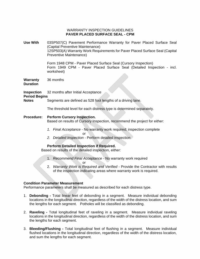
WARRANTY INSPECTION GUIDELINES PAVER PLACED SURFACE SEAL - CPM
Use With 03SP507(C) Pavement Performance Warranty for Paver Placed Surface Seal
(Capital Preventive Maintenance) 12SP503(A) Warranty Work Requirements for Paver Placed Surface Seal (Capital Preventive Maintenance) Form 1948 CPM - Paver Placed Surface Seal (Cursory Inspection) Form 1949 CPM - Paver Placed Surface Seal (Detailed Inspection - incl. worksheet)
Warranty 36 months Duration Inspection 32 months after Initial Acceptance Period Begins Notes Segments are defined as 528 foot lengths of a driving lane.
The threshold level for each distress type is determined separately. Procedure: Perform Cursory Inspection.
Based on results of Cursory Inspection, recommend the project for either:
1. Final Acceptance - No warranty work required; inspection complete or
2. Detailed Inspection - Perform detailed inspection
Perform Detailed Inspection if Required. Based on results of the detailed inspection, either:
1. Recommend Final Acceptance - No warranty work required or
2. Warranty Work is Required and Verified - Provide the Contractor with results of the inspection indicating areas where warranty work is required.
Condition Parameter Measurement Performance parameters shall be measured as described for each distress type. 1. Debonding - Total linear feet of debonding in a segment. Measure individual debonding
locations in the longitudinal direction, regardless of the width of the distress location, and sum the lengths for each segment. Potholes will be classified as debonding.
2. Raveling - Total longitudinal feet of raveling in a segment. Measure individual raveling
locations in the longitudinal direction, regardless of the width of the distress location, and sum the lengths for each segment.
3. Bleeding/Flushing - Total longitudinal feet of flushing in a segment. Measure individual
flushed locations in the longitudinal direction, regardless of the width of the distress location, and sum the lengths for each segment.

4. Average rut depth - Measure the rut depth for each wheel path independently at 65', 200', 330', 460'. The average of these four measurements is the average rut depth for the right or left wheel path. Use only the largest (deepest) average rut depth when evaluating the segment with the threshold value.
Cursory Inspection The purpose of this inspection is to rule out the possibility that warranty work is required. If the worst segments of the project appear to be below distress threshold limits, no warranty work is required and the project can be accepted. If it appears that one or more distress threshold limits may be exceeded, a Detailed Inspection is required. Cursory Inspection Procedure: Form 1948 1. Perform a windshield survey of the entire project location. Based solely on visual
examination and estimated measurements, approximate the individual distress quantities for the worst segment(s) of each distress type and record on the Cursory Inspection Form:
3. Determine if any of the following distress threshold conditions exist:
a. Any 4 segments combined - Do any 4 or more segments combined exhibit bleeding/flushing, debonding or raveling in excess of the following combined segment performance parameter threshold limits?
- Bleeding/Flushing exceeds 5% of the segment length (26.4 feet); or
- Debonding exceeds 5% of the segment length (26.4 feet); or
- Raveling exceeds 8% of the segment length (42.2 feet).
b. Any 1 segment - Does any 1 or more segment exhibit bleeding/flushing, debonding,
raveling or rutting in excess of the following single segment performance parameter threshold limits?
- Bleeding/Flushing exceeds 10% of the segment length (52.8 feet); or
- Debonding exceeds 10% of the segment length (52.8 feet); or
- Raveling exceeds 10% of the segment length (52.8 feet); or
- Average rut depth exceeds 1/4 inch (either right or left wheel path) .
3. If any condition above is true:
a. Perform Detailed Inspection
b. Provide a description of the magnitude and location(s) of the distress condition(s) observed which justify the Detailed Inspection.
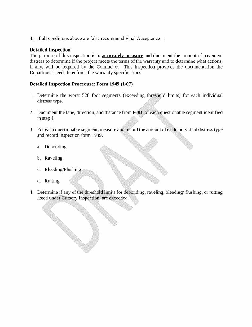
4. If all conditions above are false recommend Final Acceptance . Detailed Inspection The purpose of this inspection is to accurately measure and document the amount of pavement distress to determine if the project meets the terms of the warranty and to determine what actions, if any, will be required by the Contractor. This inspection provides the documentation the Department needs to enforce the warranty specifications. Detailed Inspection Procedure: Form 1949 (1/07) 1. Determine the worst 528 foot segments (exceeding threshold limits) for each individual
distress type.
2. Document the lane, direction, and distance from POB, of each questionable segment identified in step 1
3. For each questionable segment, measure and record the amount of each individual distress type and record inspection form 1949.
a. Debonding
b. Raveling
c. Bleeding/Flushing
d. Rutting
4. Determine if any of the threshold limits for debonding, raveling, bleeding/ flushing, or rutting
listed under Cursory Inspection, are exceeded.
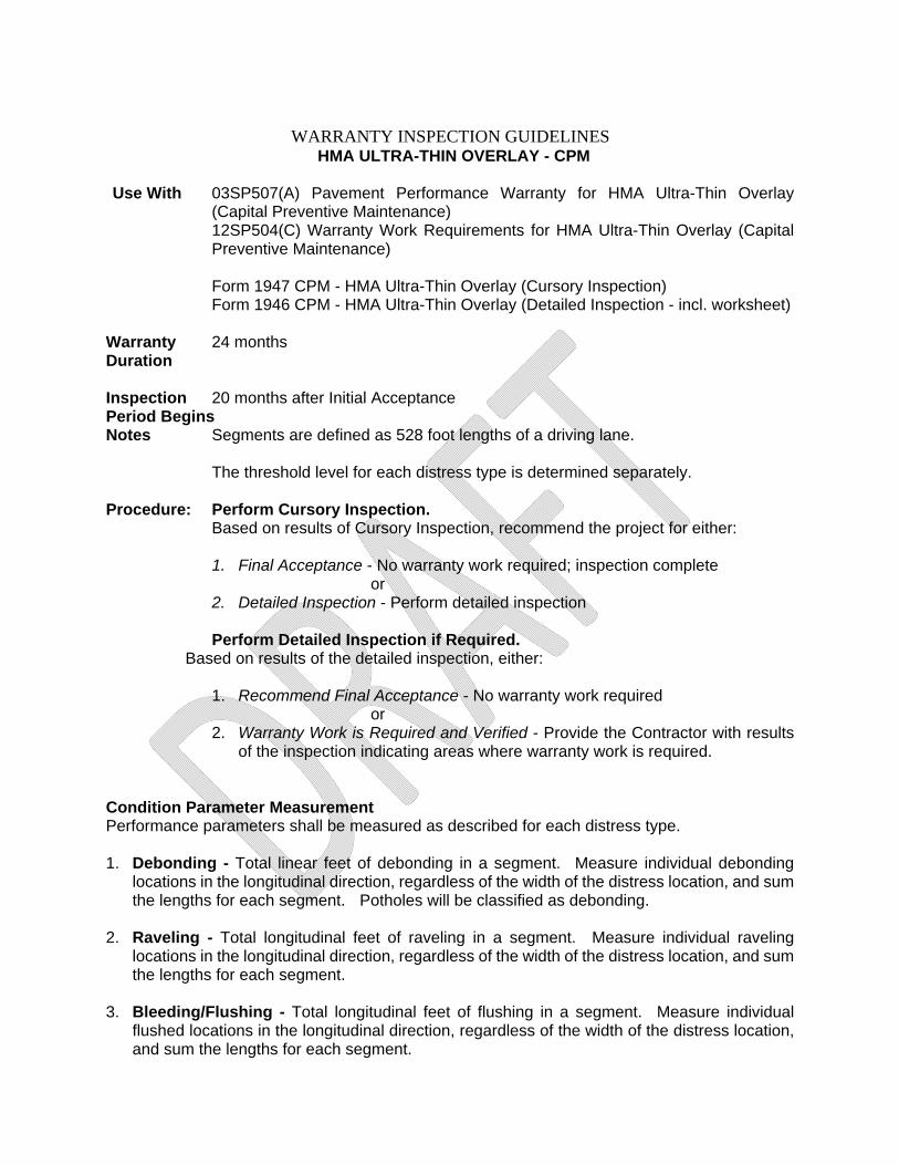
WARRANTY INSPECTION GUIDELINES HMA ULTRA-THIN OVERLAY - CPM
Use With 03SP507(A) Pavement Performance Warranty for HMA Ultra-Thin Overlay
(Capital Preventive Maintenance) 12SP504(C) Warranty Work Requirements for HMA Ultra-Thin Overlay (Capital Preventive Maintenance) Form 1947 CPM - HMA Ultra-Thin Overlay (Cursory Inspection) Form 1946 CPM - HMA Ultra-Thin Overlay (Detailed Inspection - incl. worksheet)
Warranty 24 months Duration Inspection 20 months after Initial Acceptance Period Begins Notes Segments are defined as 528 foot lengths of a driving lane.
The threshold level for each distress type is determined separately. Procedure: Perform Cursory Inspection.
Based on results of Cursory Inspection, recommend the project for either:
1. Final Acceptance - No warranty work required; inspection complete or
2. Detailed Inspection - Perform detailed inspection
Perform Detailed Inspection if Required. Based on results of the detailed inspection, either:
1. Recommend Final Acceptance - No warranty work required or
2. Warranty Work is Required and Verified - Provide the Contractor with results of the inspection indicating areas where warranty work is required.
Condition Parameter Measurement Performance parameters shall be measured as described for each distress type. 1. Debonding - Total linear feet of debonding in a segment. Measure individual debonding
locations in the longitudinal direction, regardless of the width of the distress location, and sum the lengths for each segment. Potholes will be classified as debonding.
2. Raveling - Total longitudinal feet of raveling in a segment. Measure individual raveling
locations in the longitudinal direction, regardless of the width of the distress location, and sum the lengths for each segment.
3. Bleeding/Flushing - Total longitudinal feet of flushing in a segment. Measure individual
flushed locations in the longitudinal direction, regardless of the width of the distress location, and sum the lengths for each segment.

4. Average rut depth - Measure the rut depth for each wheel path independently at 65', 200', 330', 460'. The average of these four measurements is the average rut depth for the right or left wheel path. Use only the largest (deepest) average rut depth when evaluating the segment with the threshold value.
Cursory Inspection The purpose of this inspection is to rule out the possibility that warranty work is required. If the worst segments of the project appear to be below distress threshold limits, no warranty work is required and the project can be accepted. If it appears that one or more distress threshold limits may be exceeded, a Detailed Inspection is required. Cursory Inspection Procedure: Form 1947 1. Perform a windshield survey of the entire project location. Based solely on visual
examination and estimated measurements, approximate the individual distress quantities for the worst segment(s) of each distress type and record on the Cursory Inspection Form:
4. Determine if any of the following distress threshold conditions exist:
a. Any 4 segments combined - Do any 4 or more segments combined exhibit bleeding/flushing, debonding or raveling in excess of the following combined segment performance parameter threshold limits?
- Bleeding/Flushing exceeds 5% of the segment length (26.4 feet); or
- Debonding exceeds 5% of the segment length (26.4 feet); or
- Raveling exceeds 8% of the segment length (42.2 feet).
b. Any 1 segment - Does any 1 or more segment exhibit bleeding/flushing, debonding,
raveling or rutting in excess of the following single segment performance parameter threshold limits?
- Bleeding/Flushing exceeds 10% of the segment length (52.8 feet); or
- Debonding exceeds 10% of the segment length (52.8 feet); or
- Raveling exceeds 10% of the segment length (52.8 feet); or
- Average rut depth exceeds 1/4 inch (either right or left wheel path).
3. If any condition above is true:
a. Perform Detailed Inspection
b. Provide a description of the magnitude and location(s) of the distress condition(s) observed which justify the Detailed Inspection.
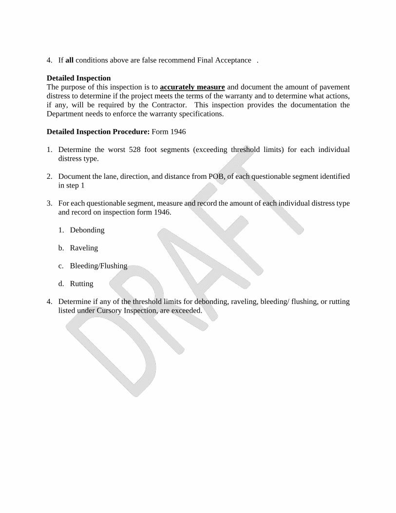
4. If all conditions above are false recommend Final Acceptance . Detailed Inspection The purpose of this inspection is to accurately measure and document the amount of pavement distress to determine if the project meets the terms of the warranty and to determine what actions, if any, will be required by the Contractor. This inspection provides the documentation the Department needs to enforce the warranty specifications. Detailed Inspection Procedure: Form 1946 1. Determine the worst 528 foot segments (exceeding threshold limits) for each individual
distress type.
2. Document the lane, direction, and distance from POB, of each questionable segment identified in step 1
3. For each questionable segment, measure and record the amount of each individual distress type and record on inspection form 1946.
1. Debonding
b. Raveling
c. Bleeding/Flushing
d. Rutting
4. Determine if any of the threshold limits for debonding, raveling, bleeding/ flushing, or rutting
listed under Cursory Inspection, are exceeded.
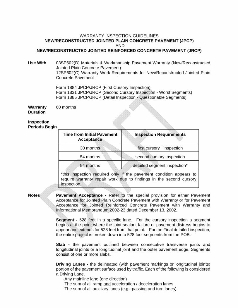
WARRANTY INSPECTION GUIDELINES NEW/RECONSTRUCTED JOINTED PLAIN CONCRETE PAVEMENT (JPCP)
AND NEW/RECONSTRUCTED JOINTED REINFORCED CONCRETE PAVEMENT (JRCP)
Use With 03SP602(D) Materials & Workmanship Pavement Warranty (New/Reconstructed
Jointed Plain Concrete Pavement) 12SP602(C) Warranty Work Requirements for New/Reconstructed Jointed Plain Concrete Pavement Form 1884 JPCP/JRCP (First Cursory Inspection) Form 1831 JPCP/JRCP (Second Cursory Inspection - Worst Segments) Form 1885 JPCP/JRCP (Detail Inspection - Questionable Segments)
Warranty 60 months Duration Inspection Periods Begin
Time from Initial Pavement
Acceptance Inspection Requirements
30 months first cursory inspection
54 months second cursory inspection
54 months detailed segment inspection*
*this inspection required only if the pavement condition appears to require warranty repair work due to findings in the second cursory inspection.
Notes Pavement Acceptance - Refer to the special provision for either Pavement
Acceptance for Jointed Plain Concrete Pavement with Warranty or for Pavement Acceptance for Jointed Reinforced Concrete Pavement with Warranty and Informational Memorandum 2002-23 dated December 13, 2002.
Segment - 528 feet in a specific lane. For the cursory inspection a segment begins at the point where the joint sealant failure or pavement distress begins to appear and extends for 528 feet from that point. For the Final detailed inspection, the entire project is broken down into 528 foot segments from the POB.
Slab - the pavement outlined between consecutive transverse joints and longitudinal joints or a longitudinal joint and the outer pavement edge. Segments consist of one or more slabs.
Driving Lanes - the delineated (with pavement markings or longitudinal joints) portion of the pavement surface used by traffic. Each of the following is considered a Driving Lane.
-Any mainline lane (one direction) -The sum of all ramp and acceleration / deceleration lanes -The sum of all auxiliary lanes (e.g.: passing and turn lanes)
Condition Parameters - Each condition parameter has a threshold level applied to each segment and a maximum number of defective segments before corrective action is required. A segment is defective if the threshold level is exceeded.
Longitudinal Joint Designation - All inspections relate to the driving lane as defined in the warranty special provision. For tallying joint sealant failure and pavement distress (spalling), consider the entire perimeter of the slab in all cases. The condition parameter of the full joint associated with the slab being evaluated is considered even though two adjacent slabs may share the same interior longitudinal joint.
Procedure Perform Cursory Warranty Inspection.
The Contractor will not be required to take corrective measures as a result of this first inspection unless the Engineer determines emergency repairs are necessary for public safety.
Perform Second Cursory Warranty Inspection. Identify the worst segments. If it appears that one or more distress threshold limit may be exceeded, a Detailed Segment Inspection is required.
Perform Detailed Segment Inspection (if required). Determine whether the Contractor will be required to do warranty repair work.
Condition Parameters Measured There are eight condition parameters applied to concrete pavements. Each condition parameter has a threshold level per 528 foot segment before the segment is determined to be defective and a maximum number of defective segments for each driving lane before corrective work is required. Some condition parameters also have a threshold level per slab within the segment. In most cases, all it will take is one defective segment per mile for each driving lane before corrections are required. Refer to the special provision to determine the various segment and/or slab threshold limits and maximum defective segments per driving lane. 1. Transverse Cracks must be visible for at least 5 feet to be counted as a crack. A transverse
crack is one that does not vary by more than 45 degrees in the transverse direction. It can be either straight or irregular in direction. Count the number of transverse cracks within the segment. Compare the total to the threshold level to determine if the segment is defective. Compare number of defective segments to the maximum number allowed to determine if warranty work is required
2. Longitudinal Cracks must be visible for at least 5 feet to be counted as a crack. A longitudinal
crack is one that does not vary more than 45 degrees in the longitudinal direction. It can exist anywhere within the driving lane. Measure the total length of longitudinal cracks within the segment. Compare the measured length to threshold level to determine if the segment is defective. Compare the number of defective segments to the maximum number allowed to determine if warranty work is required
3. Map Cracking is defined as interconnecting or variable spaced cracks in a random orientation and pattern. These can occur anywhere on the surface of the pavement. Mid-slab spalling is considered to result from advanced map cracking. This condition parameter is measured
by area since the individual cracks are sometimes hard to see and measure. Measure this condition as it relates to each driving lane. The threshold limit is based on the total affected area per segment and the number of defective segments per driving lane.
4. Spalling is generally associated with the transverse or longitudinal joint or the pavement
edge. It is defined as broken or missing pieces, exceeding two square inches, contiguous with the perimeter slab edges. Measure this condition as it relates to the pavement slab. The threshold limit is based on the total perimeter length of spall per slab and a maximum number of slabs per segment that exceed the limit. If this number is exceeded, then the segment is defective. Compare number of defective segments to the maximum number allowed to determine if warranty work is required
5. Scaling is defined as visible, exposed, rough surface texture caused by loss of either
aggregate or mortar. An example of scaling is “pop out” from clay balls or foreign materials in the slab. Measure the area of this distress and compare to the threshold limit for the slab. The segment threshold limit is based on the total distressed area per slab and a maximum number of slabs per segment that exceed the limit. If this number is exceeded, then the segment is defective. Compare number of defective segments to the maximum number allowed to determine if warranty work is required
6. Corner Cracking is generally diagonal near the slab corner, may be of any length, and
intersects the transverse and longitudinal pavement joints on the outer edge of slab. Sometimes corner cracks may result in a loss of adjacent material that may look like spalling. Count the number of these cracks in each segment and compare to the threshold limit to determine if the segment is defective. Compare number of defective segments to the maximum number allowed to determine if warranty work is required
7. Joint Sealant Failure for neoprene seals is defined by the following characteristics; twisted
rolled seals, poor compression set, surface extrusion or missing seal. In hot poured rubber seals failure is defined as loss of adhesion or cohesion. In either case, the loss of material integrity consisting of either adhesive failure (de-bonding), cohesive failure (material separation) or the complete loss of sealant material will be considered a joint sealant failure. Neoprene and Hot Poured Rubber seals do not need to be evaluated independently.
The total length of seal failure is divided by the total seal length, both longitudinal and transverse, on the perimeter of the slab to determine failure percentage. Compare the failure percentage to the threshold limit for the slab. If the threshold limit is exceeded, the slab is defective. Tally the number of defective slabs in the segment. Compare this number with the threshold limit. If this number is exceeded, then the segment is defective. Compare number of defective segments to the maximum number allowed to determine if warranty work is required.
Example: A JPCP slab of 12 feet has 48 feet (12x4) of perimeter joint seals. The slab threshold limit is ten percent of this length (4.8 feet). Two slabs in the segment exceeding this amount will result in a defective segment.
8. Shattered Slabs typically have a pattern of diagonal or looping cracks which may intersect transverse and longitudinal joints and cracks. The pavement slab is broken into four or more sections by full depth cracks. Generally it will take at least two intersecting cracks in the slab to create this condition. This condition is not allowed in any amount on any portion of the project.
First Cursory Inspection - Form 1884 The purpose of this inspection is to determine if the warranted pavement is developing distresses (condition parameters) that could eventually require warranty repairs by the Contractor. The Contractor will not be required to take corrective measures as a result of this first cursory inspection unless the Engineer determines emergency repairs are necessary for public safety. The Engineer can make this determination any time during the warranty period and doesn’t have to wait until the first inspection. Prior to doing the first cursory inspection read the Special Provision for Materials & Workmanship Pavement Warranty. Become familiar with the provisions of the warranty, particularly the condition parameters covered by the warranty. These are detailed in the Appendix of the special provision. Perform a windshield survey of all warranted pavement. Based solely on visual examination and estimated measurements, approximate the individual distress quantities for the worst segments of each distress type. If the contract includes multiple routes, complete a separate form for each route. Inspect all driving lanes. Lengths and areas of surface distresses do not have to be measured during the first inspection. Use the comment area of the form to describe the type, direction, location and lane where pavement distresses are observed. If necessary attach additional sheets for comments. Distribute the form as required. Details which should be noted for the first cursory inspection include, but are not limited to, the following: 1. Approximate distress location (i.e. 1 mile north of the POB, or at the intersection of...) 2. The lane, ramp or shoulder where the distress was noted and the associated direction. 3. The distress quantity, in general terms (i.e. minor amounts of longitudinal cracking; every joint
has loss of sealant). 4. Areas where temporary maintenance makes it difficult to determine the type of distress, (i.e.
presence of cold patching material). Second Cursory Inspection- Worst Segments - Form 1831 The purpose of this inspection is to rule out the possibility that warranty work is required. If the worst segments of the project appear to fall below distress threshold limits, no warranty work is required by the Contractor and the project can be closed out. If it appears that one or more distress threshold limit may be exceeded, conduct a Detailed Segment Inspection. Prior to conducting the second cursory inspection, read the Special Provision for Materials & Workmanship Pavement Warranty. Become familiar with the provisions of the warranty, particularly the condition parameters covered by the warranty and the threshold levels for each condition parameter. These are detailed in the Appendix of the special provision. Begin the second cursory inspection with a drive through of all warranted pavement. Inspect all driving lanes including ramps. Once the worst locations have been identified, document the
problems and supplement the form with photographs. If the contract includes multiple routes, complete a separate report for each route. All problem segments must be evaluated in a specific lane. Lay out evaluation segments beginning at the point where the joint sealant failure or pavement distress begins to appear. Reference each segment by direction of travel, road direction, lane and by physical reference such as station or mile point. For this inspection the evaluated segments need not be contiguous or in the same lane or direction. Lengths and areas of surface distresses can be estimated. After inspecting the areas on the project showing the most distress, evaluate the measurements on the Second Cursory Inspection form to determine if the condition parameter threshold limits are exceeded. If the number of defective segments does not exceed the maximum criteria, the warranty bond can be released and the project closed out. If distress levels occur above the maximum criteria a Detailed Segment Inspection must be performed to determine if corrective action will be required by the Contractor. Regardless of the need for a Detailed Segment Inspection, distribute the Second Cursory Inspection Report form as required. Detailed Segment Inspection- Questionable Segments - Form (1885) The purpose of this inspection is to accurately measure and document the amount of pavement distress and to determine if the Contractor will be required to do warranty repair work. This determination is a two-step process requiring an evaluation of the severity of distresses in each segment and the determination of the number of defective segments. When doing the detailed inspection, evaluate the entire project to determine the number of questionable segments per driving lane. Questionable segments are those which exhibit one or more distresses but which may not exceed the condition parameters threshold limit within the segment (may not be a defective segment). Starting at the POB divide the project into 528 foot segments for each individual mainline lane. For ramps, acceleration, deceleration, and auxiliary lanes, divide the aggregate total into 528 foot segments. Document any segment where any distress is observed giving the segment number, lane or ramp designation, and direction of travel. Repeat this process until all driving lane segments are inspected for the entire project. Tally the distress quantity measurements, calculate the number of segments where condition parameter threshold limits are exceeded (defective segments). Determine if the allowable number of defective segments has been exceeded triggering the need for warranty work. If distress levels fall below the threshold limits, distribute the inspection form, release the warranty bond and close out the project. Corrective Action - Send the Detailed Segment Inspection report to the Contractor with a transmittal letter summarizing the condition parameters (surface distress) exceeding both the maximum threshold limits and maximum allowable segments as defined in the warranty special provision. The transmittal letter should cover the following information: 1. The required corrective action to be completed by the Contractor.
2. The date by which the work must be completed. 3. A request for the Contractor’s proposed course of action to do the work, including methods,
materials and maintaining traffic. This plan should be received a minimum of ten days prior to starting the work.
4. The need for the Contractor to obtain a permit prior to starting the work 5. The need for the Contractor to supply documentation that insurance required by the original
contract is in effect during the warranty repair work period. 6. The 15 calendar day time frame in which to dispute the distresses resulting from materials or
workmanship. The dispute must be filed in writing citing specific reasons for the Contractor’s position. Indicate the Department will consider the Contractor’s position and may elect to initiate the forensic investigation described in the warranty special provision.
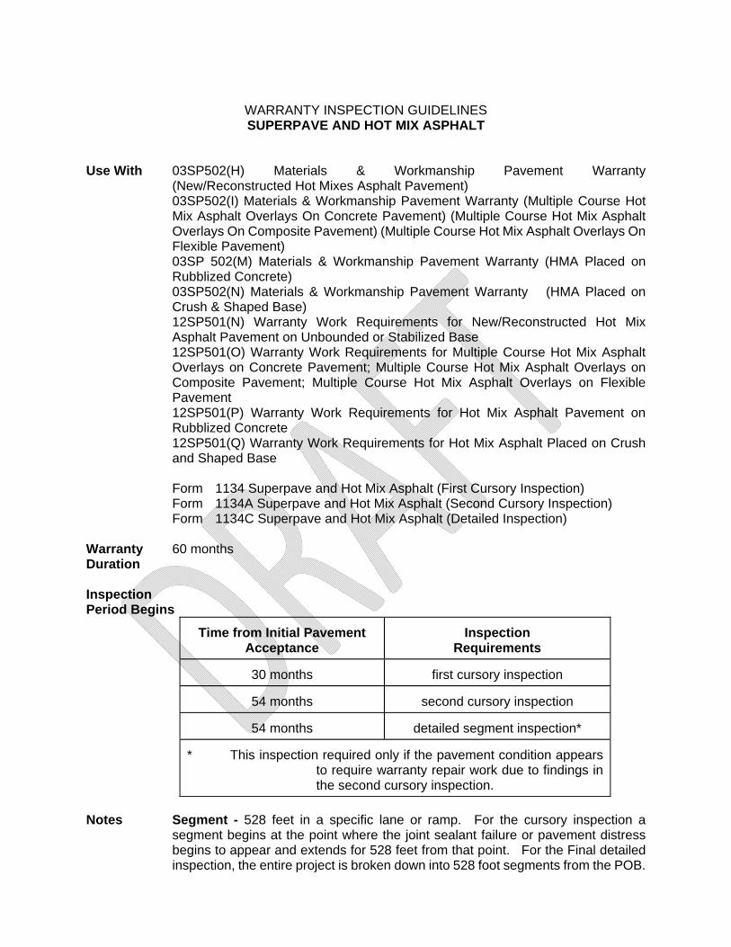
WARRANTY INSPECTION GUIDELINES SUPERPAVE AND HOT MIX ASPHALT
Use With 03SP502(H) Materials & Workmanship Pavement Warranty
(New/Reconstructed Hot Mixes Asphalt Pavement) 03SP502(I) Materials & Workmanship Pavement Warranty (Multiple Course Hot Mix Asphalt Overlays On Concrete Pavement) (Multiple Course Hot Mix Asphalt Overlays On Composite Pavement) (Multiple Course Hot Mix Asphalt Overlays On Flexible Pavement) 03SP 502(M) Materials & Workmanship Pavement Warranty (HMA Placed on Rubblized Concrete) 03SP502(N) Materials & Workmanship Pavement Warranty (HMA Placed on Crush & Shaped Base) 12SP501(N) Warranty Work Requirements for New/Reconstructed Hot Mix Asphalt Pavement on Unbounded or Stabilized Base 12SP501(O) Warranty Work Requirements for Multiple Course Hot Mix Asphalt Overlays on Concrete Pavement; Multiple Course Hot Mix Asphalt Overlays on Composite Pavement; Multiple Course Hot Mix Asphalt Overlays on Flexible Pavement 12SP501(P) Warranty Work Requirements for Hot Mix Asphalt Pavement on Rubblized Concrete 12SP501(Q) Warranty Work Requirements for Hot Mix Asphalt Placed on Crush and Shaped Base
Form 1134 Superpave and Hot Mix Asphalt (First Cursory Inspection) Form 1134A Superpave and Hot Mix Asphalt (Second Cursory Inspection) Form 1134C Superpave and Hot Mix Asphalt (Detailed Inspection)
Warranty 60 months Duration Inspection Period Begins
Time from Initial Pavement
Acceptance Inspection
Requirements
30 months first cursory inspection
54 months second cursory inspection
54 months detailed segment inspection* * This inspection required only if the pavement condition appears
to require warranty repair work due to findings in the second cursory inspection.
Notes Segment - 528 feet in a specific lane or ramp. For the cursory inspection a
segment begins at the point where the joint sealant failure or pavement distress begins to appear and extends for 528 feet from that point. For the Final detailed inspection, the entire project is broken down into 528 foot segments from the POB.

Driving Lanes - the delineated (with pavement markings) portion of the pavement surface used by traffic. Each of the following is considered a “Driving Lane”:
-Any mainline lane (one direction) -The sum of all ramp and acceleration / deceleration lanes -The sum of all auxiliary lanes (e.g.: passing and turn lanes)
Procedure: Perform Cursory Warranty Inspection.
The Contractor will not be required to take corrective measures as a result of this first inspection unless the Engineer determines emergency repairs are necessary for public safety.
Perform Second Cursory Warranty Inspection. Identify the worst segments. If it appears that one or more distress threshold limit may be exceeded, a Detailed Inspection is required.
Perform Detailed Inspection (if required). Determine whether the Contractor will be required to do warranty repair work.
Condition Parameters (distress type) Measurement Each distress type has a threshold level applied to each segment and a maximum number of defective segments before corrective action is required. A segment is defective if the threshold level is exceeded. The Warranty Special Provision contained in the contract proposal describes the pavement distress covered under the warranty, threshold limits, and the maximum number of segment criteria for each pavement distress.
First Cursory Inspection - Form 1134 The purpose of this inspection is to determine if the warranted pavement is developing distresses (condition parameters) that could eventually require warranty repairs by the Contractor. The Contractor will not be required to take corrective measures as a result of this first inspection unless the Engineer determines emergency repairs are necessary for public safety. The Engineer can make this determination any time during the warranty period and doesn’t have to wait until the first inspection to make this determination. Prior to doing the first cursory inspection, read the applicable special provision and become familiar with the provisions of the warranty, particularly the condition parameters (distress types) covered by the warranty. Perform a windshield survey of the entire location length. Based solely on visual examination and estimated measurements, approximate the individual distress quantities for the worst segment(s) of each distress type and record on the Cursory Inspection Form (Form 1134) If the contract includes multiple routes, complete a separate form for each route. Inspect all driving lanes as defined in the warranty special provision. Lengths and areas of surface distresses do not have to be measured during the first inspection. Use the comment area of the form to describe the type, direction, location and lane where pavement distresses are observed. If necessary attach additional sheets for comments. Distribute the form as required. Appropriate comments for the first cursory inspection include, but are not limited to, the following:
1. Approximate distress location (i.e. 1 mile north of the POB, or at the intersection of...). 2. The lane, ramp or shoulder where the distress was noted and the associated direction. 3. In general terms describe the distress quantity (i.e. minor amounts of longitudinal cracking,
or, every joint has loss of sealant). 4. Areas where temporary maintenance makes it difficult to determine the type of distress,
(i.e. presence of cold patching material). Second Cursory Inspection- Worst Segments Form 1134A The purpose of this inspection is to comply with the monitoring requirements in the Special Provision and to rule out the possibility that warranty work is required. If the worst segments of the project appear to fall below distress threshold limits, no warranty work is required by the Contractor and the project can be closed out. If it appears that one or more distress threshold limit may be exceeded, conduct a Detailed Segment Inspection. Prior to conducting the second cursory inspection, read the appropriate special provision and become familiar with the provisions of the warranty, particularly the condition parameters (distress types) covered by the warranty and the threshold levels for each condition parameter. Begin the second cursory inspection of the warranted pavement with a drive-thru inspection. Inspect all driving lanes including ramps. Once the worst locations have been identified, document the problems using Form 1134A and supplement the form with photographs. If the contract includes multiple routes, complete a separate report for each route. All problem locations must be evaluated in a specific lane for a full segment. The segment should begin at the point where the pavement distress begins to appear. Reference each segment by direction of travel, road direction, lane and physical reference such as station or mile point. The segments need not be contiguous or in the same lane or direction. Lengths and areas of surface distresses can be estimated. Evaluation of Cursory Inspection Results Upon completion of the second cursory inspection tally the distress quantity measurements, and calculate the number of segments where distress threshold limits are exceeded. If distress levels fall below the maximum criteria, distribute the inspection form, release the warranty bond and close out the project. If distress levels occur above the maximum criteria a Detailed Inspection must be preformed to determine if corrective action will be required by the Contractor. Regardless of whether or not the Detailed Inspection is required, distribute the Second Cursory Inspection report as required. Detailed Inspection - Form 1134C
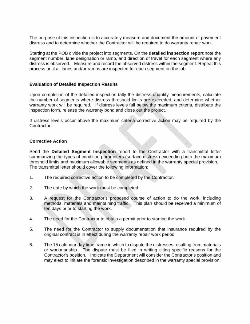
The purpose of this inspection is to accurately measure and document the amount of pavement distress and to determine whether the Contractor will be required to do warranty repair work. Starting at the POB divide the project into segments. On the detailed inspection report note the segment number, lane designation or ramp, and direction of travel for each segment where any distress is observed. Measure and record the observed distress within the segment. Repeat this process until all lanes and/or ramps are inspected for each segment on the job. Evaluation of Detailed Inspection Results Upon completion of the detailed inspection tally the distress quantity measurements, calculate the number of segments where distress threshold limits are exceeded, and determine whether warranty work will be required. If distress levels fall below the maximum criteria, distribute the inspection form, release the warranty bond and close out the project. If distress levels occur above the maximum criteria corrective action may be required by the Contractor. Corrective Action Send the Detailed Segment Inspection report to the Contractor with a transmittal letter summarizing the types of condition parameters (surface distress) exceeding both the maximum threshold limits and maximum allowable segments as defined in the warranty special provision. The transmittal letter should cover the following information: 1. The required corrective action to be completed by the Contractor. 2. The date by which the work must be completed. 3. A request for the Contractor’s proposed course of action to do the work, including
methods, materials and maintaining traffic. This plan should be received a minimum of ten days prior to starting the work.
4. The need for the Contractor to obtain a permit prior to starting the work 5. The need for the Contractor to supply documentation that insurance required by the
original contract is in effect during the warranty repair work period. 6. The 15 calendar day time frame in which to dispute the distresses resulting from materials
or workmanship. The dispute must be filed in writing citing specific reasons for the Contractor’s position. Indicate the Department will consider the Contractor’s position and may elect to initiate the forensic investigation described in the warranty special provision.
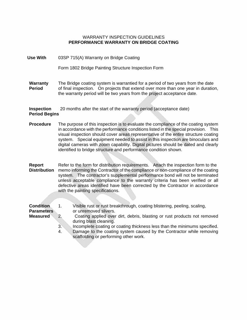
WARRANTY INSPECTION GUIDELINES PERFORMANCE WARRANTY ON BRIDGE COATING
Use With 03SP 715(A) Warranty on Bridge Coating
Form 1802 Bridge Painting Structure Inspection Form Warranty The Bridge coating system is warrantied for a period of two years from the date Period of final inspection. On projects that extend over more than one year in duration,
the warranty period will be two years from the project acceptance date. Inspection 20 months after the start of the warranty period (acceptance date) Period Begins Procedure The purpose of this inspection is to evaluate the compliance of the coating system
in accordance with the performance conditions listed in the special provision. This visual inspection should cover areas representative of the entire structure coating system. Special equipment needed to assist in this inspection are binoculars and digital cameras with zoom capability. Digital pictures should be dated and clearly identified to bridge structure and performance condition shown.
Report Refer to the form for distribution requirements. Attach the inspection form to the Distribution memo informing the Contractor of the compliance or non-compliance of the coating
system. The contractor’s supplemental performance bond will not be terminated unless acceptable compliance to the warranty criteria has been verified or all defective areas identified have been corrected by the Contractor in accordance with the painting specifications.
Condition 1. Visible rust or rust breakthrough, coating blistering, peeling, scaling, Parameters or unremoved slivers. Measured 2. Coating applied over dirt, debris, blasting or rust products not removed
during blast cleaning. 3. Incomplete coating or coating thickness less than the minimums specified. 4. Damage to the coating system caused by the Contractor while removing
scaffolding or performing other work.