guidelines for cleanliness hydraulic fluids and lubricantsfiles.danfoss.com/documents/design...
TRANSCRIPT
MAKING MODERN LIVING POSSIBLE
Technical Information
Hydraulic Fluids and LubricantsGuidelines for Cleanliness
powersolutions.danfoss.com
Revision history Table of revisions
Date Changed Rev
July 2014 Layout, backpage change GG
Mar 2014 Converted to Danfoss layout – DITA CMS GF
Nov 2011 Minor change GE
Oct 2010 New backpage, change of a layout, no technical change. GD
Jun 2002 First edition AA
Technical Information Design Guidelines for Hydraulic Fluid Cleanliness
2 520L0467 • Rev GG • July 2014
Initial questions and answersPurpose................................................................................................................................................................................................ 4Why is filtration necessary?...........................................................................................................................................................4Where does the dirt come from?................................................................................................................................................ 4
Assembly dirt................................................................................................................................................................................ 4Operating dirt...............................................................................................................................................................................4
How can the required cleanliness level be achieved?.........................................................................................................5Definition of β-ratio, efficiency, filter fineness ...................................................................................................................... 6
β-ratio versus filter efficiency..................................................................................................................................................7
Fluid cleanliness featuresDefinition of cleanliness levels per ISO 4406..........................................................................................................................9
Particle size definition.............................................................................................................................................................10Fluid cleanliness requirements................................................................................................................................................. 11
Selection of an appropriate filter and filtration systemClosed Circuit...................................................................................................................................................................................13
Design of a filter in the CC suction line.............................................................................................................................13Design of a filter in the CC charge circuit.........................................................................................................................13
Open Circuit .................................................................................................................................................................................... 14Design of a filter in the OC suction line............................................................................................................................ 14Design of a filter in the OC return line...............................................................................................................................14Filtration in OC with multiple pumps................................................................................................................................14
Recommendations for a new filter element.........................................................................................................................14By-pass filtration.............................................................................................................................................................................14Dirt absorption capacity, maximum differential pressure.............................................................................................. 14Why a bypass?................................................................................................................................................................................. 15Contamination indicator............................................................................................................................................................. 16Air breather ..................................................................................................................................................................................... 16What is to be Done if the Required Cleanliness Class is not Achieved? ....................................................................17Why Loop Flushing?......................................................................................................................................................................17
Taking of Fluid SamplesFluid samples...................................................................................................................................................................................18Sampling according to ISO 4021 from a system in operation....................................................................................... 18
Sampling device........................................................................................................................................................................18Sampling method.....................................................................................................................................................................19Sampling from a tank according to CETOP RP 95 H.....................................................................................................19
Working hintsScavenging and running in........................................................................................................................................................ 20Monitoring of contamination....................................................................................................................................................20
Permanent...................................................................................................................................................................................20Cyclical..........................................................................................................................................................................................21Topping up hydraulic fluid....................................................................................................................................................21Changing the element............................................................................................................................................................21
Technical Information Design Guidelines for Hydraulic Fluid Cleanliness
Contents
520L0467 • Rev GG • July 2014 3
Purpose
This leaflet is intended to assist the designer of an installation, a set or a hydrostatic drive to ensure thatthe requirement for a specific minimum cleanliness of the hydraulic fluid is met by means of designmeasures such as the selection of an optimal filter, or preferably of an economically efficient filtrationconcept. This includes start-up, operation and topping up of hydraulic fluid.
Why is filtration necessary?
In hydrostatic systems a series of sliding surfaces act as hydrostatic-hydrodynamic bearings with gapheights in the range of 10 µm. That is why dirt is the greatest enemy of hydraulic systems, sincedepending on its nature and composition it generates wear and thus shortens service lives.
This is true for all fields of mechanical engineering and it cannot be repeated often enough. At thepresent time it is not possible to predict the length of the service life of a hydrostatic unit as a function ofthe cleanliness of the hydraulic fluid. The fact that these constraints are not known for roller bearingseither, even though very many parameters have been researched for these parts in particular, shows justhow complicated these wear mechanisms are.
Although more effort is currently being concentrated on trying to measure dirt sensitivity of hydrostaticunits in short-term contamination tests, such experiments are unsuccessful because contaminationsensitivity cannot be measured like pressures or speeds. The leading manufacturers of hydrostaticequipment have therefore decided to give priority to investigating the fundamentals of wear caused bycontamination in hydrostatic units within the framework of a joint research project.
It is uncertain to what extent service life prognoses will be possible at the end of the research project, if atall. It can, however, be stated that the cleaner a system, the higher its service life expectancy.
A satisfactory service life is achieved if the cleanliness level as required below is maintained.
Where does the dirt come from?
We distinguish between two essential sources of dirt:
• contamination occurring during assembly – assembly dirt
• contamination occurring during operation – operating dirt
Assembly dirt
Different kinds of dirt occur during the various production operations: chips, moulding sand, coreresidues, cleaning-rag lint, welding beads, scale etc. Products supplied by Danfoss are therefore cleanedin modern cleaning installations after completion of machining operations on the individual parts.Careful attention is also paid to cleanliness when these clean individual parts are assembled to formhighgrade hydrostatic units. However, since dirt occurs during the final assembly in a vehicle, of a set etc.,especially during the piping work, it is advisable to flush the whole system prior to commissioning.
The basic contamination of the „clean“ hydraulic fluid supplied must also be added to the assembly dirt.As investigations have shown, new hydraulic fluid can contain basic dirt levels in excess of the cleanlinesslevel admissible for optimum operation (see section Cleanliness requirements, page 13). That is why asystem should always be filled up via a filter assembly. Particles of the same order of magnitude as thegap widths are to be considered as especially critical.
Operating dirt
Fine dirt from the surrounding environment is drawn into the hydraulic system during operation viapiston rods or other moving seals. Abrasive particles from the components are also pumped through thesystem with the fluid. A frequently underestimated source of contamination is from unsuitable ventingfacilities of fluid tanks. Fluctuations in volume cause fine dust to be drawn into the tanks, from where itcauses abrasion of the sliding combinations in the system.
Technical Information Design Guidelines for Hydraulic Fluid Cleanliness
Initial questions and answers
4 520L0467 • Rev GG • July 2014
How can the required cleanliness level be achieved?
A filtration system must be designed in such a way that it is able to retain the new dirt entering theoverall system in the filter in order to maintain the required cleanliness level throughout the wholeoperating life.
An example description:
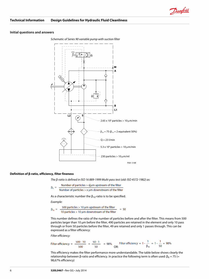
If a filter is used in the suction line or the charge circuit, the charge pump size selected - in our example17 cm3 – determines the volume flow available for filtering as a function of the speed. The followingtheoretical calculation serves to illustrate this (see the Schematic of Series 90 variable pump with suctionfilter below).
Assuming that the pump runs at a nominal speed of 1500 min-1, then at an assumed volumetric efficiencyof 90 %, a charge pump volume flow of approx. 23 l/min results.
A contamination level of 230 particles larger than 10 µm/ml has developed in the oil tank and a filter withβ35 = 75, β10 = 2 (= 50 % filtration efficiency) is fitted in the suction line. The contamination is alsodistributed uniformly in the fluid. Approximately 5.3 x 10⁶ particles larger than 10 µm per minute are nowdrawn from the tank with the charge pump flow. The filter element holds back 50 % of the particles largerthan 10 µm, so that 2.65 x 10⁶ particles larger than 10 µm reach the charge pump each minute.
If 2.65 x 10⁶ particles larger than 10 µm are also passed to the system per minute (via ventilation filters,piston rods or abrasion), there is no change in the cleanliness level. If fewer than 2.65 x 10⁶ particles largerthan 10 µm are passed to the system, a lower i. e. a better cleanliness level is achieved. However if morethan 2.65 x 10⁶ particles larger than 10 µm are passed to the system, a higher i. e. a worse cleanliness levelis achieved.
As mentioned at the beginning, this calculation is very close to conditions encountered in practice, butthese will never be so exact because particles will settle at the bottom of the tank in areas with a low flowvelocity. Nor are the particles so uniformly distributed when they pass through the filter. This example ismerely intended to illustrate the principle and it can be established that:
The cleanliness level is improved if:• the filter fineness is improved
(higher β-value for a certain particle size, i. e. β10 = 2 becomes β10 = 2.5)• the volume flow* via the filter is increased
The cleanliness level deteriorates if:• the filter fineness deteriorates
(lower β-value for a certain particle size, i. e. β10 = 2 becomes β10 = 1.8)• the volume flow via the filter is reduced.
(Note the change of the β-value shown in the diagram Retention rate as a function of the differentialpressure. The alteration of the volume flow also changes the differential pressure and hence the βvalue too. However the volume flow has more influence on the cleanliness level.)
The flow volume cannot generally be selected freely since it is determined in a closed circuit by the sizeof the charge pump. However other operating factors take priority when the charge pump size isselected. In these cases, therefore, the β-value must be varied.
However, if the β-value is increased (different filter material) without the structural dimensions of thefilter being increased, then the consequence is that:• the differential pressure rises (applies for new, uncontaminated filter element)
• the dirt absorption capacity drops (reduced service life)
Technical Information Design Guidelines for Hydraulic Fluid Cleanliness
Initial questions and answers
520L0467 • Rev GG • July 2014 5
Schematic of Series 90 variable pump with suction filter
P001 318E
2.65 x 10⁶ particles > 10 mm/min
b35 = 75 (b10 = 2 equivalent 50%)
Q = 23 l/min
5.3 x 10⁶ particles > 10 mm/min
230 particles > 10 mm/ml
L2 S
Servo
M
A
B
L1
Definition of β-ratio, efficiency, filter fineness
The β-ratio is defined in ISO 16 889-1999 Multi-pass test (old: ISO 4572-1982) as:
As a characteristic number the β10-ratio is to be specified.
Example:
This number defines the ratio of the number of particles before and after the filter. This means from 500particles larger than 10 µm before the filter, 490 particles are retained in the element and only 10 passthrough or from 50 particles before the filter, 49 are retained and only 1 passes through. This can beexpressed as a filter efficiency:
Filter efficiency:
OR:
This efficiency makes the filter performance more understandable. The table below shows clearly therelationship between β-ratio and efficiency. In practice the following term is often used: βX = 75 (=98,67% efficiency)
Technical Information Design Guidelines for Hydraulic Fluid Cleanliness
Initial questions and answers
6 520L0467 • Rev GG • July 2014
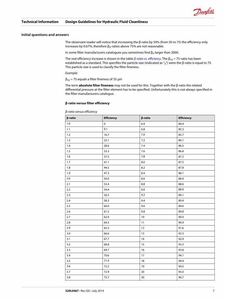
The observant reader will notice that increasing the β-ratio by 50% (from 50 to 75) the efficiency onlyincreases by 0.67%, therefore βX-ratios above 75% are not reasonable.
In some filter manufacturers catalogues you sometimes find βX larger than 2000.
The real efficiency increase is shown in the table β-ratio vs. efficiency. The β10 = 75-ratio has beenestablished as a standard. This specifies the particle size (indicated as “X“) were the β-ratio is equal to 75.This particle size is used to classify the filter fineness.
Example:
β35 = 75 equals a filter fineness of 35 µm
The term absolute filter fineness may not be used for this. Together with the β-ratio the relateddifferential pressure at the filter element has to be specified. Unfortunately this is not always specified inthe filter manufacturers catalogue.
β-ratio versus filter efficiency
β-ratio versus efficiency
β-ratio Efficiency β-ratio Efficiency
1.0 0 6.4 84.4
1.1 9.1 6.8 85.3
1.2 16.7 7.0 85.7
1.3 23.1 7.2 86.1
1.4 28.6 7.4 86.5
1.5 33.3 7.6 86.8
1.6 37.5 7.8 87.2
1.7 41.1 8.0 87.5
1.8 44.5 8.2 87.8
1.9 47.3 8.4 88.1
2.0 50.0 8.6 88.4
2.1 52.4 8.8 88.6
2.2 54.4 9.0 88.9
2.3 56.5 9.2 89.1
2.4 58.3 9.4 89.4
2.5 60.0 9.6 89.6
2.6 61.5 9.8 89.8
2.7 62.9 10 90.0
2.8 64.3 11 90.9
2.9 65.5 12 91.6
3.0 66.6 13 92.3
3.1 67.7 14 92.9
3.2 68.8 15 93.3
3.3 69.7 16 93.8
3.4 70.6 17 94.1
3.5 71.4 18 94.4
3.6 72.2 19 94.5
3.7 72.9 20 95.0
3.8 73.7 30 96.7
Technical Information Design Guidelines for Hydraulic Fluid Cleanliness
Initial questions and answers
520L0467 • Rev GG • July 2014 7
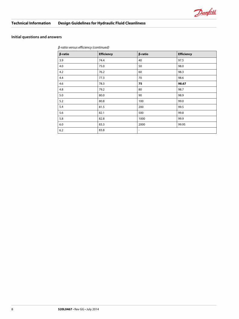
β-ratio versus efficiency (continued)
β-ratio Efficiency β-ratio Efficiency
3.9 74.4 40 97.5
4.0 75.0 50 98.0
4.2 76.2 60 98.3
4.4 77.3 70 98.6
4.6 78.3 75 98.67
4.8 79.2 80 98.7
5.0 80.0 90 98.9
5.2 80.8 100 99.0
5.4 81.5 200 99.5
5.6 82.1 500 99.8
5.8 82.8 1000 99.9
6.0 83.3 2000 99.95
6.2 83.8 -
Technical Information Design Guidelines for Hydraulic Fluid Cleanliness
Initial questions and answers
8 520L0467 • Rev GG • July 2014
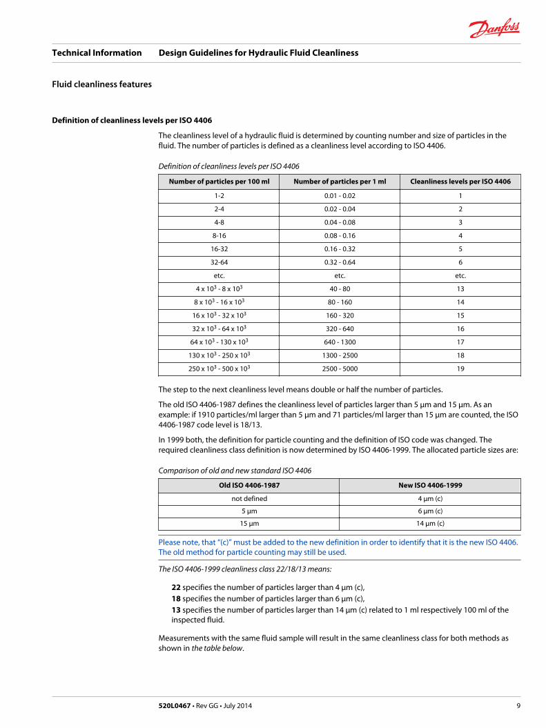
Definition of cleanliness levels per ISO 4406
The cleanliness level of a hydraulic fluid is determined by counting number and size of particles in thefluid. The number of particles is defined as a cleanliness level according to ISO 4406.
Definition of cleanliness levels per ISO 4406
Number of particles per 100 ml Number of particles per 1 ml Cleanliness levels per ISO 4406
1-2 0.01 - 0.02 1
2-4 0.02 - 0.04 2
4-8 0.04 - 0.08 3
8-16 0.08 - 0.16 4
16-32 0.16 - 0.32 5
32-64 0.32 - 0.64 6
etc. etc. etc.
4 x 10³ - 8 x 10³ 40 - 80 13
8 x 10³ - 16 x 103 80 - 160 14
16 x 103 - 32 x 103 160 - 320 15
32 x 103 - 64 x 103 320 - 640 16
64 x 103 - 130 x 103 640 - 1300 17
130 x 103 - 250 x 103 1300 - 2500 18
250 x 103 - 500 x 103 2500 - 5000 19
The step to the next cleanliness level means double or half the number of particles.
The old ISO 4406-1987 defines the cleanliness level of particles larger than 5 µm and 15 µm. As anexample: if 1910 particles/ml larger than 5 µm and 71 particles/ml larger than 15 µm are counted, the ISO4406-1987 code level is 18/13.
In 1999 both, the definition for particle counting and the definition of ISO code was changed. Therequired cleanliness class definition is now determined by ISO 4406-1999. The allocated particle sizes are:
Comparison of old and new standard ISO 4406
Old ISO 4406-1987 New ISO 4406-1999
not defined 4 μm (c)
5 μm 6 μm (c)
15 μm 14 μm (c)
Please note, that “(c)” must be added to the new definition in order to identify that it is the new ISO 4406.The old method for particle counting may still be used.
The ISO 4406-1999 cleanliness class 22/18/13 means:
22 specifies the number of particles larger than 4 µm (c),18 specifies the number of particles larger than 6 µm (c),13 specifies the number of particles larger than 14 μm (c) related to 1 ml respectively 100 ml of theinspected fluid.
Measurements with the same fluid sample will result in the same cleanliness class for both methods asshown in the table below.
Technical Information Design Guidelines for Hydraulic Fluid Cleanliness
Fluid cleanliness features
520L0467 • Rev GG • July 2014 9
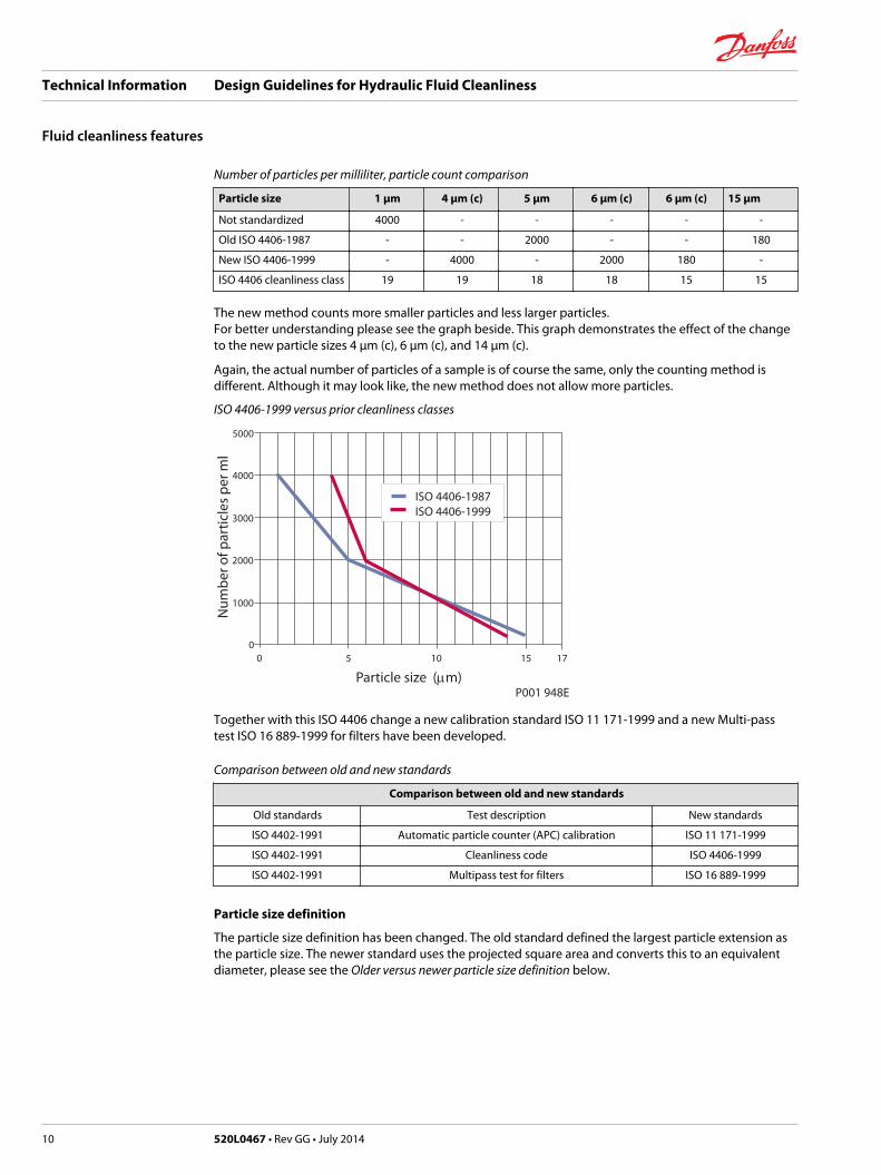
Number of particles per milliliter, particle count comparison
Particle size 1 μm 4 μm (c) 5 μm 6 μm (c) 6 μm (c) 15 μm
Not standardized 4000 - - - - -
Old ISO 4406-1987 - - 2000 - - 180
New ISO 4406-1999 - 4000 - 2000 180 -
ISO 4406 cleanliness class 19 19 18 18 15 15
The new method counts more smaller particles and less larger particles. For better understanding please see the graph beside. This graph demonstrates the effect of the changeto the new particle sizes 4 µm (c), 6 µm (c), and 14 µm (c).
Again, the actual number of particles of a sample is of course the same, only the counting method isdifferent. Although it may look like, the new method does not allow more particles.
ISO 4406-1999 versus prior cleanliness classes
00
5 10
1000
2000
3000
4000
5000
15 17
Particle size (mm)
Nu
mb
er o
f par
ticl
es p
er m
l
ISO 4406-1987ISO 4406-1999
P001 948E
Together with this ISO 4406 change a new calibration standard ISO 11 171-1999 and a new Multi-passtest ISO 16 889-1999 for filters have been developed.
Comparison between old and new standards
Comparison between old and new standards
Old standards Test description New standards
ISO 4402-1991 Automatic particle counter (APC) calibration ISO 11 171-1999
ISO 4402-1991 Cleanliness code ISO 4406-1999
ISO 4402-1991 Multipass test for filters ISO 16 889-1999
Particle size definition
The particle size definition has been changed. The old standard defined the largest particle extension asthe particle size. The newer standard uses the projected square area and converts this to an equivalentdiameter, please see the Older versus newer particle size definition below.
Technical Information Design Guidelines for Hydraulic Fluid Cleanliness
Fluid cleanliness features
10 520L0467 • Rev GG • July 2014
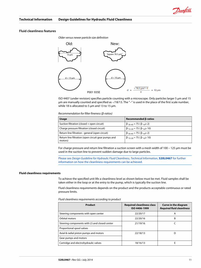
Older versus newer particle size definition
13 µm
d = 13 µm
Square 78.5 µm2
d = 10 µm
Old: New:
P001 935E
ISO 4407 (under revision) specifies particle counting with a microscope. Only particles larger 5 µm and 15µm are manually counted and specified as –/18/13. The “–” is used in the place of the first scale number,while 18 is allocated to 5 µm and 13 to 15 µm.
Recommendation for filter fineness (β-ratios)
Usage Recommended β-ratios
Suction filtration (closed + open circuit) β-35-45 = 75 ( β-10≥ 2)
Charge pressure filtration (closed circuit) β-15-20 = 75 ( β-10≥ 10)
Return line filtration - general (open circuit) β-35-45 = 75 ( β-10≥ 2)
Return line filtration (open circuit gear pumps andmotors)
β-15-20 = 75 ( β-10≥ 10)
For charge pressure and return line filtration a suction screen with a mesh width of 100 – 125 µm must beused in the suction line to prevent sudden damage due to large particles.
Please see Design Guideline for Hydraulic Fluid Cleanliness, Technical Information, 520L0467 for furtherinformation on how the cleanliness requirements can be achieved.
Fluid cleanliness requirements
To achieve the specified unit life a cleanliness level as shown below must be met. Fluid samples shall betaken either in the loop or at the entry to the pump, which is typically the suction line.
Fluid cleanliness requirements depends on the product and the products acceptable continuous or ratedpressure limits.
Fluid cleanliness requirements according to product
Product Required cleanliness classISO 4406-1999
Curve in the diagramRequired fluid cleanliness
Steering components with open center 22/20/17 A
Orbital motors 22/20/16 B
Steering components with LS and closed center 21/19/16 C
Proportional spool valves
Axial & radial piston pumps and motors 22/18/13 D
Gear pumps and motors
Cartridge and electrohydraulic valves 18/16/13 E
Technical Information Design Guidelines for Hydraulic Fluid Cleanliness
Fluid cleanliness features
520L0467 • Rev GG • July 2014 11
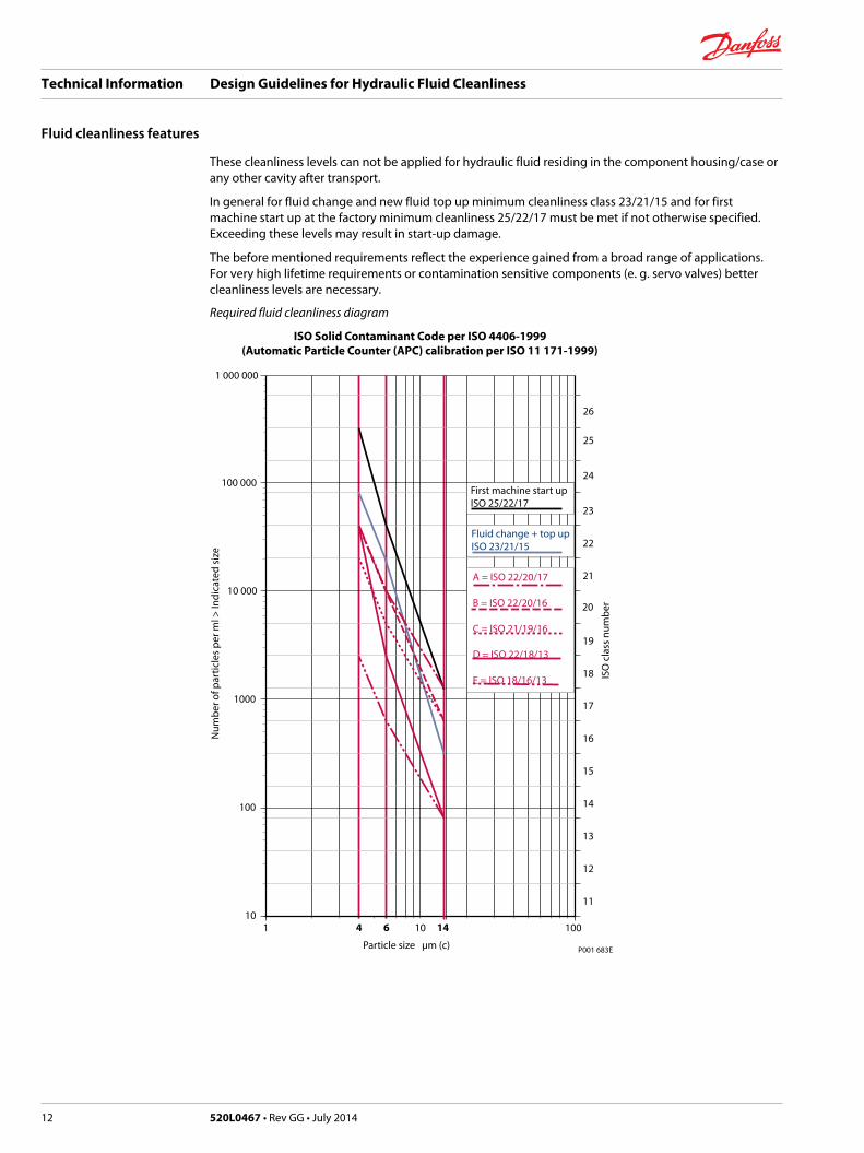
These cleanliness levels can not be applied for hydraulic fluid residing in the component housing/case orany other cavity after transport.
In general for fluid change and new fluid top up minimum cleanliness class 23/21/15 and for firstmachine start up at the factory minimum cleanliness 25/22/17 must be met if not otherwise specified.Exceeding these levels may result in start-up damage.
The before mentioned requirements reflect the experience gained from a broad range of applications.For very high lifetime requirements or contamination sensitive components (e. g. servo valves) bettercleanliness levels are necessary.
Required fluid cleanliness diagram
10
100
1000
10 000
100 000
11
12
13
14
15
16
17
18
19
20
21
22
23
1 10 100
Nu
mb
er o
f par
ticl
es p
er m
l > In
dic
ated
siz
e
ISO
cla
ss n
um
ber
Particle size µm (c)
4 146
24
25
ISO Solid Contaminant Code per ISO 4406-1999(Automatic Particle Counter (APC) calibration per ISO 11 171-1999)
1 000 000
26
P001 683E
First machine start upISO 25/22/17
Fluid change + top upISO 23/21/15
A = ISO 22/20/17
B = ISO 22/20/16
C = ISO 21/19/16
D = ISO 22/18/13
E = ISO 18/16/13
Technical Information Design Guidelines for Hydraulic Fluid Cleanliness
Fluid cleanliness features
12 520L0467 • Rev GG • July 2014
Example:
The design is explained below taking an SPV 9/075 with a charge pump volume of 17 cm3 by way ofexample. A continuous pressure of 240 bar is assumed. Accordingly in section 3 the cleanliness class18/13 to ISO 4406 results from curve A.
Closed Circuit
Design of a filter in the CC suction line
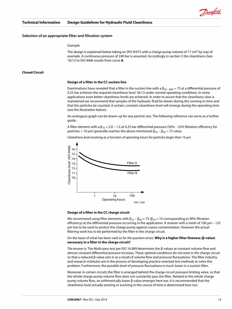
Examinations have revealed that a filter in the suction line with a β35 – β45 = 75 at a differential pressure of0.25 bar achieves the required cleanliness level 18/13 under normal operating conditions. In someapplications even better cleanliness levels are achieved. In order to assure that the cleanliness class ismaintained we recommend that samples of the hydraulic fluid be drawn during the running-in time andthat the particles be counted. A certain, constant cleanliness level will emerge during the operating time(see the illustration below).
An analogous graph can be drawn up for any particle size. The following reference can serve as a furtherguide.
A filter element with a β10 = 2.0 – 1.5 at 0.25 bar differential pressure (50% – 33% filtration efficiency forparticles > 10 µm) generally reaches the above mentioned β35 – β45 = 75 value.
Cleanliness level evolving as a function of operating hours for particles larger than 15 µm
Filter A
Filter B
16
15
14
13
12
1110
Cle
anlin
ess
leve
l (IS
O 4
406)
1 10 100
P001 320E Operating hours
Design of a filter in the CC charge circuit
We recommend using filter elements with β15 – β20 = 75 (β10 = 10 corresponding to 90% filtrationefficiency) at the differential pressure occurring in the application. A strainer with a mesh of 100 µm – 125µm has to be used to protect the charge pump against coarse contamination. However the actualfiltering work has to be performed by the filter in the charge circuit.
On the basis of what has been said so far the question arises: Why is a higher filter fineness (β-value)necessary in a filter in the charge circuit?
The answer is: The Multi-pass test per ISO 16 889 determines the β-values at constant volume flow andalmost constant differential pressure increase. These optimal conditions do not exist in the charge circuitso that a reduced β-value sets in as a result of volume flow and pressure fluctuations. The filter industryand research institutes are in the process of developing practice-oriented test methods to solve thisproblem. Furthermore, the possible level of pressure fluctuations is much lower in a suction filter.
Moreover in certain circuits the filter is arranged behind the charge circuit pressure limiting valve, so thatthe whole charge pump volume flow does not constantly pass the filter. Related to the whole chargepump volume flow, an arithmetically lower β-value emerges here too. It is recommended that thecleanliness level actually existing or evolving in the course of time is determined here too.
Technical Information Design Guidelines for Hydraulic Fluid Cleanliness
Selection of an appropriate filter and filtration system
520L0467 • Rev GG • July 2014 13
Open Circuit
Design of a filter in the OC suction line
Unlike the situation in the closed circuit, the whole main volume flow is taken from the tank. That is whythese suction filters must be adequately dimensioned in order to achieve appropriate differentialpressures and service lives. On the other hand a lower filter fineness can be selected, since a highervolume flow is available. For further information, please see next page.
Design of a filter in the OC return line
In the case of return line filters in open circuits, special attention must be paid to discontinuous volumeflows through working cylinders with differing area ratio. Under certain circumstances it might thereforebe advisable to select a larger filter than would be necessitated by the suction line alone. In any case astrainer with a mesh size of 100 – 125 µm should be provided in the suction line.
Filtration in OC with multiple pumps
A machine with several pumps using the same reservoir may use one filter only to save costs. Every circuitmust be protected by a suction strainer with 100 –125 µm mesh.
This mesh equals theoretically: β100-150 = 75
This term should not be used for a screen. The off-line filtration may feed other functions and circuits likethe steering equipment.
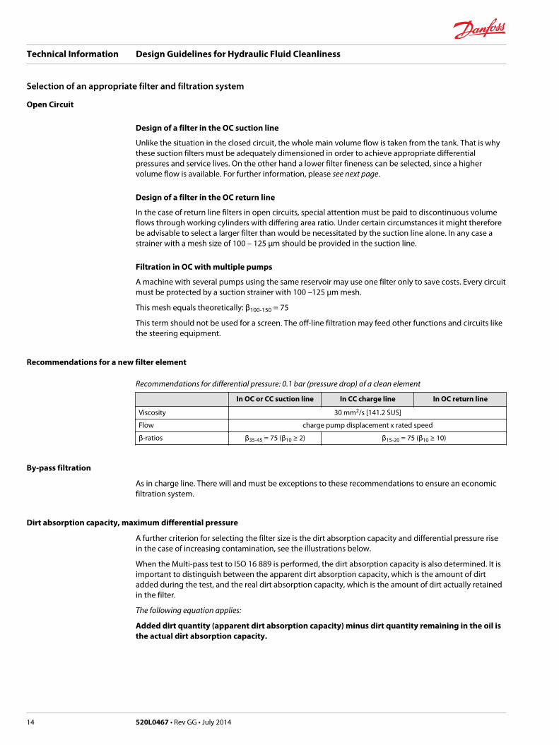
Recommendations for a new filter element
Recommendations for differential pressure: 0.1 bar (pressure drop) of a clean element
In OC or CC suction line In CC charge line In OC return line
Viscosity 30 mm2/s [141.2 SUS]
Flow charge pump displacement x rated speed
β-ratios β35-45 = 75 (β10 ≥ 2) β15-20 = 75 (β10 ≥ 10)
By-pass filtration
As in charge line. There will and must be exceptions to these recommendations to ensure an economicfiltration system.
Dirt absorption capacity, maximum differential pressure
A further criterion for selecting the filter size is the dirt absorption capacity and differential pressure risein the case of increasing contamination, see the illustrations below.
When the Multi-pass test to ISO 16 889 is performed, the dirt absorption capacity is also determined. It isimportant to distinguish between the apparent dirt absorption capacity, which is the amount of dirtadded during the test, and the real dirt absorption capacity, which is the amount of dirt actually retainedin the filter.
The following equation applies:
Added dirt quantity (apparent dirt absorption capacity) minus dirt quantity remaining in the oil isthe actual dirt absorption capacity.
Technical Information Design Guidelines for Hydraulic Fluid Cleanliness
Selection of an appropriate filter and filtration system
14 520L0467 • Rev GG • July 2014
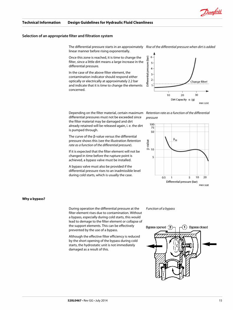
The differential pressure starts in an approximatelylinear manner before rising exponentially.
Once this zone is reached, it is time to change thefilter, since a little dirt means a large increase in thedifferential pressure.
In the case of the above filter element, thecontamination indicator should respond eitheroptically or electrically at approximately 2.2 barand indicate that it is time to change the elementsconcerned.
Rise of the differential pressure when dirt is added
Depending on the filter material, certain maximumdifferential pressures must not be exceeded sincethe filter material may be damaged and dirtalready retained will be released again, i. e. the dirtis pumped through.
The curve of the β-value versus the differentialpressure shows this (see the illustration Retentionrate as a function of the differential pressure).
If it is expected that the filter element will not bechanged in time before the rupture point isachieved, a bypass valve must be installed.
A bypass valve must also be provided if thedifferential pressure rises to an inadmissible levelduring cold starts, which is usually the case.
Retention rate as a function of the differentialpressure
Why a bypass?
During operation the differential pressure at thefilter element rises due to contamination. Withouta bypass, especially during cold starts, this wouldlead to demage to the filter element or collapse ofthe support elements. This can be effectivelyprevented by the use of a bypass.
Although the effective filter efficiency is reducedby the short opening of the bypass during coldstarts, the hydrostatic unit is not immediatelydamaged as a result of this.
Function of a bypass
Technical Information Design Guidelines for Hydraulic Fluid Cleanliness
Selection of an appropriate filter and filtration system
520L0467 • Rev GG • July 2014 15
The cleanliness level simply deteriorates as a function of the time during which the bypass is in operationand as a function of the newly generated particles. Working with an open bypass for several hours ordays should be avoided. This condition can be monitored reliably with a contamination indicator (see Contamination indicator on page 16). The system operator thus determines the service life of thehydrostatic units and the rest of the system by regularly checking the contamination level of the filter andchanging the filter elements in time.
It is important to understand that if used as explained above, a bypass is always better than the suddenrelease of a particle or a dirt cloud due to damage to an element whereby the cloud is passed throughthe whole system (including the high-pressure circuit) and finally lands in the tank after irreparabledamage is sustained by the sliding parts. If there is no contamination indicator either, this damage is notnoticed and it may be that the system is operated for a long time with this unintentional „bypass“ (afterthe element has been destroyed!) until overheating caused by reduced efficiency of the hydrostatic unitsis recognized. This then turns out to be much more expensive than the additional bypass and thecontamination indicator would have been (see Contamination indicator).
A bypass should be arranged as shown above or even further away from the element if the design allowsthis. Under certain circumstances it may even be a design advantage if the filter elements are to bebolted directly on to the pump (charge circuit filtration).
C Caution
A bypass may never be situated in the base of the filter element since the dirt settles in this area and isflushed into the system again.
Contamination indicator
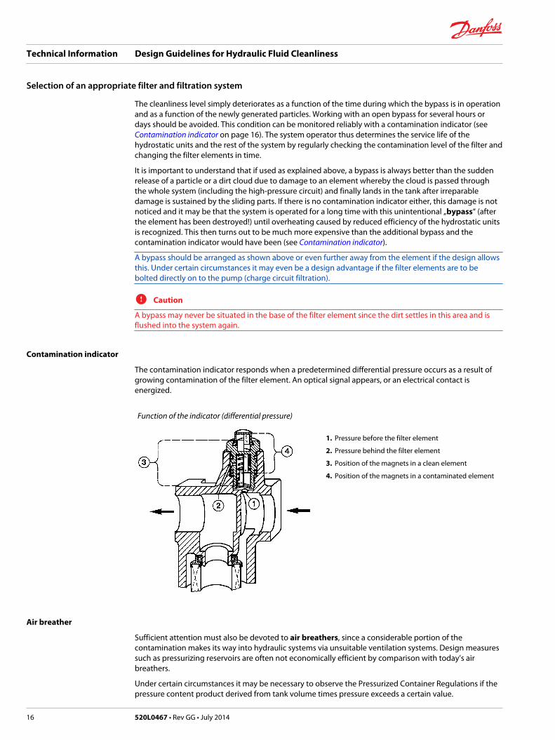
The contamination indicator responds when a predetermined differential pressure occurs as a result ofgrowing contamination of the filter element. An optical signal appears, or an electrical contact isenergized.
Function of the indicator (differential pressure)
1. Pressure before the filter element
2. Pressure behind the filter element
3. Position of the magnets in a clean element
4. Position of the magnets in a contaminated element
Air breather
Sufficient attention must also be devoted to air breathers, since a considerable portion of thecontamination makes its way into hydraulic systems via unsuitable ventilation systems. Design measuressuch as pressurizing reservoirs are often not economically efficient by comparison with today’s airbreathers.
Under certain circumstances it may be necessary to observe the Pressurized Container Regulations if thepressure content product derived from tank volume times pressure exceeds a certain value.
Technical Information Design Guidelines for Hydraulic Fluid Cleanliness
Selection of an appropriate filter and filtration system
16 520L0467 • Rev GG • July 2014
Unfortunately there is no standard for air breathers corresponding to the Multi-pass test to ISO 16 889.The filter fineness quoted by the manufacturer of the air breathers has to be relied on. This does notpermit comparisons between manufacturers A and B since, as already mentioned, there are nostandardized tests.
Generally speaking the fineness of the air breathers must be equivalent to or better than the “workingfilters” present in the system.
Therefore only the βx = 75 values and the given filter fineness of the air breathers can be taken asstandard values.
What is to be Done if the Required Cleanliness Class is not Achieved?
A brief reminder
It was explained before that the cleanliness level is influenced by:
• the β-value (filter fineness, filtration ratio)• the volume flow through the filter
If the required cleanliness level is not achieved using the 17 cm3/U charge pump and the β10 = 75 filter, itis not necessarily expedient to use a larger charge pump. This may necessitate a larger filter since thedifferential pressure more quickly reaches the limit of p = 0.25 bar (risk of cavitation) with a clean filterelement, which leads to insufficient service life of the element. The energy balance also deteriorates as aresult of the higher power loss.
In this case filters with a higher β-value must be used. However, since the higher β-values generally alsoinvolve higher differential pressures, it is often also necessary to move the filter to the charge circuit. Ifthe filter elements are designed accordingly, higher differential pressures are admissible here so that theoverall dimensions of the filter can be reduced - representing an installation advantage. It must also beclarified and checked to what extent new contamination can be reduced and prevented.
It was explained before that inadequate ventilation facilities are a cause of fresh contamination. Animprovement of the cleanliness level can often be achieved by using ventilation filters with better filterfineness, especially for applications with working cylinders with differing area ratios.
For the design of the ventilation filter the differential pressure (caused by the differential air volume flow)must be kept as low as possible in order to prevent cavitation in the suction area of the pumps. It shouldalso be checked whether unsuitable piston rod seals or leaks are the cause.
Remember
Dirt which does not enter the system or is not caused by wear need not be removed by filtration.
Why Loop Flushing?
Filtration is intended to remove contamination from the hydraulic fluid. For this, however, thecontamination must be passed to the filter element. In a closed circuit without circuit purging, existingcontamination can only be removed from the system with the oil leaking from the pistons, the controlvalve etc. Since only particles smaller than the leak gap width can leave the closed circuit, the remainingparticles stay in the circuit and can lead to erosion damage in areas with high flow velocities.
This can be avoided by circuit purging, i. e. by forcing 5–6 l/min from the low pressure circuit via an spoolvalve and a purge relief valve.
The contamination flushed out in this way (including particles larger than the leak gap width) can now bepassed to the filter element installed in the system and be removed.
Technical Information Design Guidelines for Hydraulic Fluid Cleanliness
Selection of an appropriate filter and filtration system
520L0467 • Rev GG • July 2014 17
Fluid samples
Fluid samples must be drawn very carefully into appropriate bottles to prevent extraneous dirt from,falsifying the sample result.
The sample bottle should contain a label with the following information:• Sample number
• Source of sample
• Sampling method
• Date and time of sampling
• Nature of fluid
• Comments/remarks if necessary
Sampling according to ISO 4021 from a system in operation
Sampling points should be provided at the design stage of the hydraulic installation. They should bearranged in the turbulent main flow.
C Caution
Take precautionary measures to protect personnel and equipment.
Sampling device
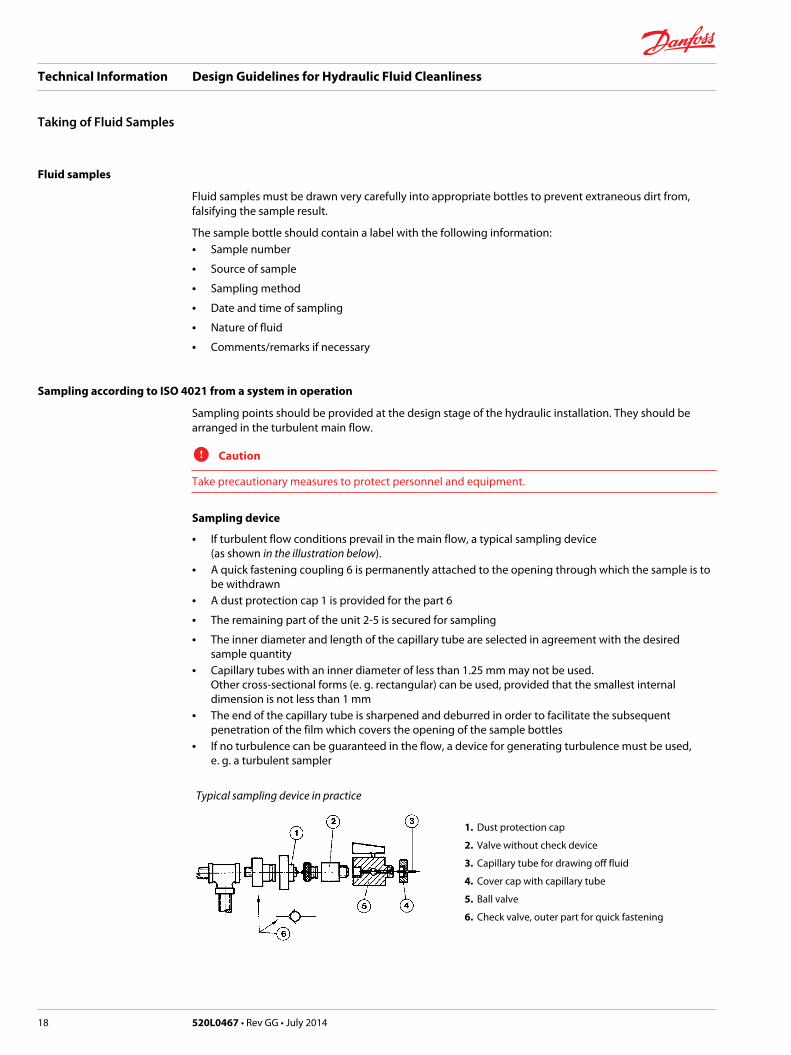
• If turbulent flow conditions prevail in the main flow, a typical sampling device (as shown in the illustration below).
• A quick fastening coupling 6 is permanently attached to the opening through which the sample is tobe withdrawn
• A dust protection cap 1 is provided for the part 6
• The remaining part of the unit 2-5 is secured for sampling
• The inner diameter and length of the capillary tube are selected in agreement with the desiredsample quantity
• Capillary tubes with an inner diameter of less than 1.25 mm may not be used. Other cross-sectional forms (e. g. rectangular) can be used, provided that the smallest internaldimension is not less than 1 mm
• The end of the capillary tube is sharpened and deburred in order to facilitate the subsequentpenetration of the film which covers the opening of the sample bottles
• If no turbulence can be guaranteed in the flow, a device for generating turbulence must be used, e. g. a turbulent sampler
Typical sampling device in practice
1. Dust protection cap
2. Valve without check device
3. Capillary tube for drawing off fluid
4. Cover cap with capillary tube
5. Ball valve
6. Check valve, outer part for quick fastening
Technical Information Design Guidelines for Hydraulic Fluid Cleanliness
Taking of Fluid Samples
18 520L0467 • Rev GG • July 2014
Sampling method
• Ball valve 5 is opened
• Allow at least 200 ml fluid to flow through the sampling device before collecting the fluid
• Without closing the ball valve, place the sample bottle in the position for collecting the fluid
• Pierce the protective film covering the bottle opening with the sharp end of the capillary tube
• Draw a sample of not more than 90 % and not less than 50 % of the bottle volume.
• When a sufficient sample quantity has been collected, remove the sample bottle before stopping theflow with the ball valve
• Seal the sample bottle immediately after withdrawing the capillary tube
• If a sampling device with quick-fastening coupling is used, the removable parts of the samplingdevice are to be dismantled and all other fluid traces are to be removed by flushing with a suitablesolvent
• Immediately after dismantling the dust protection cap is replaced on the permanently mounted partof the quick fastening coupling.
Sampling from a tank according to CETOP RP 95 H
Sampling from the tank should only be carried out if it is not possible to sample from the main flow.Clean the outer surface of the tank around the places from which the sample is to be drawn.
Sampling:
The fluid in the tank should be mixed well in order to ensure that the sample is typical. To this end warmup the system by running it under operating conditions. Then draw a sample (at least 150 ml) with theaid of a pipette or a cleaned disposable syringe. Pass the pipette about half way down into the fluid.
Ensure that the pipette does not touch the side walls of the tank or come too close to the bottom. Fill thecontents of the pipette into the sample bottle and seal this carefully. Cover the tank again or close it withclean covering film if further samples are required.
Technical Information Design Guidelines for Hydraulic Fluid Cleanliness
Taking of Fluid Samples
520L0467 • Rev GG • July 2014 19
The frequency and intensity of the maintenance work to be performed depend on the burden generatedby environmental influences and on the workload.
Special attention must always be paid to the operational suitability and cleanness of the hydraulic fluid.
Scavenging and running in
Before a hydraulic system is commissioned, the assembly dirt must be removed. This is best done byflushing the whole installation with a portable filter unit. Mineral oil (or another medium compatible withthe hydraulic fluid to be used subsequently) is pumped through the whole system or parts of the systemat the highest possible flow velocity. The assembly dirt is filtered in the filter unit.
During this process the elements of the built-in filters are to be removed. Small or less sensitive systemscan also be scavenged with the built-in filters during the running-in process. It must be ensured that thesystem is run without load but with a displacement which is gradually increased up to maximum.
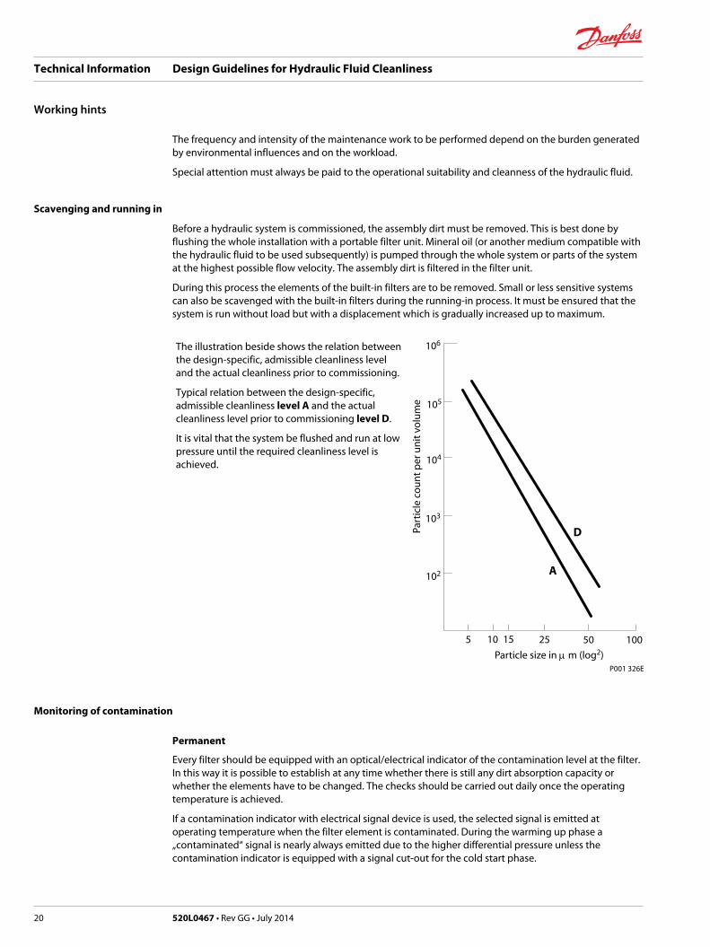
The illustration beside shows the relation betweenthe design-specific, admissible cleanliness leveland the actual cleanliness prior to commissioning.
Typical relation between the design-specific,admissible cleanliness level A and the actualcleanliness level prior to commissioning level D.
It is vital that the system be flushed and run at lowpressure until the required cleanliness level isachieved.
Part
icle
co
un
t p
er u
nit
vo
lum
e
Particle size in m m (log2)
102
10 15 5025 100
P001 326E
5
103
104
105
106
D
A
Monitoring of contamination
Permanent
Every filter should be equipped with an optical/electrical indicator of the contamination level at the filter.In this way it is possible to establish at any time whether there is still any dirt absorption capacity orwhether the elements have to be changed. The checks should be carried out daily once the operatingtemperature is achieved.
If a contamination indicator with electrical signal device is used, the selected signal is emitted atoperating temperature when the filter element is contaminated. During the warming up phase a„contaminated“ signal is nearly always emitted due to the higher differential pressure unless thecontamination indicator is equipped with a signal cut-out for the cold start phase.
Technical Information Design Guidelines for Hydraulic Fluid Cleanliness
Working hints
20 520L0467 • Rev GG • July 2014
Cyclical
With regular monitoring, filters are suitable as wear surveillance elements for the components of thehydraulic system. If the operator keeps a log of filter changes, it can be assumed in the event of shorterchanging intervals that the wear of the system components is increasing. The origin of the maincontamination can be ascertained by analysing a fluid sample and the contaminated element. Acomparison of the results with the materials used allows preventive maintenance before a completefailure interrupts production or operation. Adherence to the required cleanliness level is checked bymeasuring the contamination and this ensures that no premature wear or failure occurs.
These samples must be drawn at specially designed sampling points as explained before.
Topping up hydraulic fluid
Any fluid used to top up losses should always be poured in via a fine filter in order to maintain thecleanliness class. Where appropriate facilities are available, the return flow filter can be used. It isadvisable to provide a permanent connection which should be included in considerations at the designstage. Any opening of the tank/reservoir for maintenance purposes (topping up hydraulic fluid, sampling,changing filter elements in built-in tanks etc.) should always be avoided as far as possible by anexpedient design. Even though some ventilation filters have a so-called filling screen (mesh width >100 µm), this still does not afford any protection against the penetration of particles of the order ofmagnitude of 10 – 100 µm.
Changing the element
If the contamination indicator shows a contaminated element, this must be changed without delay dueto the high rate of increase of pressure drop as the element becomes more contaminated. Extreme caremust be taken when changing the element. The operating instructions must be followed precisely.
The following standard values apply for filter maintenance intervals:1. 24 hours after commissioning the system2. After the running-in period (50 - 100 hours of service)3. Normal maintenance after 300 - 500 hours of service
Technical Information Design Guidelines for Hydraulic Fluid Cleanliness
Working hints
520L0467 • Rev GG • July 2014 21
Technical Information Design Guidelines for Hydraulic Fluid Cleanliness
22 520L0467 • Rev GG • July 2014
Technical Information Design Guidelines for Hydraulic Fluid Cleanliness
520L0467 • Rev GG • July 2014 23
Danfoss Power Solutions is a global manufacturer and supplier of high-quality hydraulic andelectronic components. We specialize in providing state-of-the-art technology and solutionsthat excel in the harsh operating conditions of the mobile off-highway market. Building onour extensive applications expertise, we work closely with our customers to ensureexceptional performance for a broad range of off-highway vehicles.
We help OEMs around the world speed up system development, reduce costs and bringvehicles to market faster.
Danfoss – Your Strongest Partner in Mobile Hydraulics.
Go to www.powersolutions.danfoss.com for further product information.
Wherever off-highway vehicles are at work, so is Danfoss. We offer expert worldwide supportfor our customers, ensuring the best possible solutions for outstanding performance. Andwith an extensive network of Global Service Partners, we also provide comprehensive globalservice for all of our components.
Please contact the Danfoss Power Solution representative nearest you.
Local address:
Danfoss Power Solutions GmbH & Co. OHGKrokamp 35D-24539 Neumünster, GermanyPhone: +49 4321 871 0
Danfoss Power Solutions ApSNordborgvej 81DK-6430 Nordborg, DenmarkPhone: +45 7488 2222
Danfoss Power Solutions US Company2800 East 13th StreetAmes, IA 50010, USAPhone: +1 515 239 6000
Danfoss Power Solutions(Shanghai) Co., Ltd.Building #22, No. 1000 Jin Hai RdJin Qiao, Pudong New DistrictShanghai, China 201206Phone: +86 21 3418 5200
Danfoss can accept no responsibility for possible errors in catalogues, brochures and other printed material. Danfoss reserves the right to alter its products without notice. This also applies toproducts already on order provided that such alterations can be made without changes being necessary in specifications already agreed..All trademarks in this material are property of the respective companies. Danfoss and the Danfoss logotype are trademarks of Danfoss A/S. All rights reserved.
520L0467 • Rev GG • July 2014 www.danfoss.com © Danfoss A/S, 2014
Products we offer:
• Bent Axis Motors
• Closed Circuit Axial PistonPumps and Motors
• Displays
• Electrohydraulic PowerSteering
• Electrohydraulics
• Hydraulic Power Steering
• Integrated Systems
• Joysticks and ControlHandles
• Microcontrollers andSoftware
• Open Circuit Axial PistonPumps
• Orbital Motors
• PLUS+1® GUIDE
• Proportional Valves
• Sensors
• Steering
• Transit Mixer Drives
Comatrolwww.comatrol.com
Schwarzmüller-Inverterwww.schwarzmueller-inverter.com
Turolla www.turollaocg.com
Valmovawww.valmova.com
Hydro-Gearwww.hydro-gear.com
Daikin-Sauer-Danfosswww.daikin-sauer-danfoss.com