guidelines for earthquake resistant building … · resistant building construction: earthen...
TRANSCRIPT
NBC108V2.RV9 7 December 1993
N E P A L N A T I O N A L B U I L D I N G C O D E
NBC 204 : 1994
GUIDELINES FOR EARTHQUAKE RESISTANT BUILDING CONSTRUCTION:
EARTHEN BUILDING (EB)
Government of Nepal Ministry of Physical Planning and Works
Department of Urban Development and Building Construction Babar Mahal, Kathmandu, NEPAL Reprinted : 2064
NBC108V2.RV9 7 December 1993
N E P A L N A T I O N A L B U I L D I N G C O D E
NBC 204 : 1994
GUIDELINES FOR EARTHQUAKE RESISTANT BUILDING CONSTRUCTION:
EARTHEN BUILDING (EB)
tTsflng >L % sf] ;/sf/ -dlGqkl/ifb\_ sf] ldlt @)^).$.!@ sf] lg0f{ofg';f/ :jLs[t
Government of Nepal Ministry of Physical Planning and Works
Department of Urban Development and Building Construction Babar Mahal, Kathmandu, NEPAL Reprinted : 2064
This publication represents a standard of good practice and therefore takes the form of recommendations. Compliance with it does not confer immunity from relevant legal requirements, including bylaws
NBC204V1.RV1 9 June 1994
i
Preface This Nepal Standard was prepared during 1993 as part of a project to prepare a National Building Code for Nepal. In 1988 the Ministry of Housing and Physical Planning (MHPP), conscious of the growing needs of Nepal's urban and shelter sectors, requested technical assistance from the United Nations Development Programme and their executing agency, United Nations Centre for Human Settlements (UNCHS). A programme of Policy and Technical Support was set up within the Ministry (UNDP Project NEP/88/054) and a number of activities have been undertaken within this framework. The 1988 earthquake in Nepal, and the resulting deaths and damage to both housing and schools, again drew attention to the need for changes and improvement in current building construction and design methods. Until now, Nepal has not had any regulations or documents of its own setting out either requirements or good practice for achieving satisfactory strength in buildings. In late 1991 the MHPP and UNCHS requested proposals for the development of such regulations and documents from international organisations in response to terms of reference prepared by a panel of experts. This document has been prepared by the subcontractor's team working within the Department of Building, the team including members of the Department and the MHPP. As part of the proposed management and implementation strategy, it has been prepared so as to conform with the general presentation requirements of the Nepal Bureau of Standards and Metrology. The subproject has been undertaken under the aegis of an Advisory Panel to the MHPP. The Advisory Panel consisted of : Mr. UB Malla, Joint Secretary, MHPP Chairman Director General, Department of Building (Mr. LR Upadhyay) Member Mr. AR Pant, Under Secretary, MHPP Member8 Director General, Department of Mines & Geology (Mr. PL Shrestha) Member Director General, Nepal Bureau of Standards & Metrology (Mr. PB Manandhar) Member Dean, Institute of Engineering, Tribhuvan University (Dr. SB Mathe) Member Project Chief, Earthquake Areas Rehabilitation & Reconstruction Project Member President, Nepal Engineers Association Member Law Officer, MHPP (Mr. RB Dange) Member Representative, Society of Consulting Architectural & Engineering Firms (SCAEF) Member
NBC204V1.RV1 9 June 1994
ii
Representative, Society of Nepalese Architects (SONA) Member Deputy Director General, Department of Building, (Mr. JP Pradhan) Member-Secretary The Subcontractor was BECA WORLEY INTERNATIONAL CONSULTANTS LTD. of New Zealand in conjunction with subconsultants who included : Golder Associates Ltd., Canada SILT Consultants P. Ltd., Nepal TAEC Consult (P.) Ltd., Nepal Urban Regional Research, USA Principal inputs to this standard came from : Mr. YK Parajuli, TAEC Mr. JK Bothara, TAEC Mr. BK Upadhyay, TAEC Mr. SL Sharma, TAEC Dr. AS Arya, Professsor Emeritur, University of Roorkee Revisions and Updated to this code came from: Mr. Purna P. Kadariya, DG, DUDBC
Mr. Kishore Thapa, DDG, DUDBC Mr. Mani Ratna Tuladhar, Sr. Div. Engineer, DUDBC Mr. Jyoti Prasad Pradhan, Ex. DG, DOB Mr. Bhubaneswor Lal Shrestha, Ex. DDG, DOB Mr. Uttam Shrestha, Architect, Architects' Module Pvt. Ltd. Mr. Manohar Lal Rajbhandrai, Sr. Structural Engineer, MR Associates Mr. Amrit Man Tuladhar, Civil Engineer, DUDBC
NBC204V1.RV1 9 June 1994
iii
TABLE OF CONTENTS Preface ......................................................................................................................................................... i 0 Foreword ......................................................................................................................................... x 0.1 Introduction ....................................................................................................................... x 0.2 Objective ............................................................................................................................. x 0.3 Background ........................................................................................................................ x 0.4 Applicability ....................................................................................................................... x 0.5 Interpretation ..................................................................................................................... x 0.6 Terminology .................................................................................................................... xi 1 Scope ............................................................................................................................................... 1 1.1 Type of Buildings Covered .............................................................................................. 1 1.2 Limitation .......................................................................................................................... 1 2 General Requirements for Earthquake-Resistance Construction ......................................... 2 2.1 Proper Site Selection ........................................................................................................ 2 2.2 Appropriate Planning ...................................................................................................... 2 2.3 Good Foundations Resting on a Firm Base .................................................................. 2 2.4 Creating a Box Effect ....................................................................................................... 2 2.5 Better Bonding Between Masonry Units ....................................................................... 2 2.6 Controlled Size and Location of Openings ................................................................... 3 3 Materials ......................................................................................................................................... 4 3.1 Mud .................................................................................................................................... 4 3.2 Adobe (Sun-Dried Clay Bricks/Blocks) ......................................................................... 4 3.3 Mud Mortar ...................................................................................................................... 4 3.4 Bamboo .............................................................................................................................. 4 3.5 Timber ............................................................................................................................... 4 4 Site Considerations ....................................................................................................................... 5 4.1 General ............................................................................................................................... 5 4.2 Site Selection ..................................................................................................................... 5 4.2.1 Geological Faults or Ruptured Areas ............................................................... 5 4.2.2 Areas Susceptible to Landslide .......................................................................... 5 4.2.3 Boulder Hazard ................................................................................................... 5 4.2.4 River Banks .......................................................................................................... 5 4.2.5 Swamp/Marshy Area .......................................................................................... 5 4.2.6 Steep Slopes .......................................................................................................... 6 4.2.7 Water-Logged Areas ........................................................................................... 6
NBC204V1.RV1 9 June 1994
iv
4.2.8 Filled Areas ........................................................................................................... 6 5 Planning .......................................................................................................................................... 7 5.1 Shape .................................................................................................................................. 7 5.2 Proportions ........................................................................................................................ 8 5.3 Storey Height .................................................................................................................... 8 5.4 Number of Storeys ............................................................................................................ 8 6 Foundation ..................................................................................................................................... 9 6.1 General ............................................................................................................................... 9 6.2 Strip Footing ..................................................................................................................... 9 6.3 Foundations on Sloping Sites ........................................................................................ 10 7 Walls ............................................................................................................................................. 11 7.1 General ............................................................................................................................. 11 7.1.1 Mud Wall Construction .................................................................................... 11 7.1.2 Rammed Earth Wall Construction ................................................................. 12 7.1.3 Adobe (Sun-Dried Bricks/Blocks) Wall Construction.................................. 13 7.2 Wall Thickness ................................................................................................................ 14 7.3 Unsupported Wall Length ............................................................................................ 14 7.4 Height of Walls ............................................................................................................... 15 7.5 Protection of Mud Walls ............................................................................................... 15 7.5.1 Foundation .......................................................................................................... 15 7.5.2 Damp Proof Course (DPC) .............................................................................. 16 7.5.3 Roof Projections ................................................................................................. 16 7.5.4 Non-Erodible Mud Plaster (NEM) .................................................................. 16 7.6 Corners and Junctions ................................................................................................... 16 8 Openings in Walls ....................................................................................................................... 17 9 Floors and Roofs .......................................................................................................................... 18 9.1 Structure .......................................................................................................................... 18 9.1.1 Posts and Capitals .............................................................................................. 18 9.1.2 Beams and Bearings .......................................................................................... 22 9.1.3 Wall Plates .......................................................................................................... 23 9.1.4 Joists and Rafters .............................................................................................. 24 9.2 Floor Finishings and Roof Coverings .......................................................................... 25 9.2.1 Bridging Materials ............................................................................................ 25
NBC204V1.RV1 9 June 1994
v
9.2.2 Floor Finishing ................................................................................................... 26 9.2.3 Roof Covering .................................................................................................... 26 9.3 Bamboo for Flooring and Roofing ............................................................................... 31 9.3.1 Bamboo Flooring ............................................................................................... 31 9.3.2 Bamboo Roofing ................................................................................................ 32 10 Seismic-Resistant Components ................................................................................................. 34 10.1 Vertical Reinforcement ................................................................................................. 34 10.1.1 Bamboo ................................................................................................................. 34 10.1.2 Timber .................................................................................................................. 35 10.2 Horizontal Bands ............................................................................................................ 36 10.2.1 Bamboo Band ...................................................................................................... 36 10.2.2 Timber Bands ...................................................................................................... 37 10.3 Gable Bands .................................................................................................................... 38 10.4 Diagonal Bracing ............................................................................................................ 39 10.5 Lateral Restrainers ........................................................................................................ 40 11 Miscellaneous ............................................................................................................................... 41 11.1 Damp-Proof Courses ..................................................................................................... 41 11.2 Drainage .......................................................................................................................... 42 APPENDIX - 1 HARVESTING AND PRESERVING BAMBOO FOR
CONSTRUCTION ......................................................................................... A1-1 1 Harvesting and Preservative Treatment ............................................................................... A1-1 1.1 Harvesting .................................................................................................................... A1-1 1.1.1 Harvesting Guidelines .................................................................................... A1-1 1.1.2 Clump Cure ..................................................................................................... A1-1 1.2 Preservative Treatment .............................................................................................. A1-2 1.2.1 Water Leaching .............................................................................................. A1-2 1.2.2 White Wash and Other Coatings ................................................................. A1-2 1.2.3 Brushing, Swabbing, Spraying and Dipping .............................................. A1-2 1.3 Fire-Retarding Treatment ......................................................................................... A1-3 1.4 Storage .......................................................................................................................... A1-3
NBC204V1.RV1 9 June 1994
vi
APPENDIX - 2 FIRE-RETARDANT TREATMENT FOR THATCH ............................. A2-1 1 General ...................................................................................................................................... A2-1 1.1 Materials Required ..................................................................................................... A2-1 1.2 Method of Preparation ............................................................................................... A2-1 1.2.1 Preparation of Stabilised Mud Mortar ....................................................... A2-1 1.2.2 Preparation of Cut-Back1 Bitumen (for NEM) .......................................... A2-1 1.2.3 Preparation of NEM Mortar ........................................................................ A2-2 1.2.4 Preparation of Cut-Back2 Bitumen for Stabilised Mud Slurry ............... A2-2 1.2.5 Preparation of Stabilised Mud Slurry1 for NEM ....................................... A2-2 1.2.6 Preparation of Stabilised Mud Slurry2 for Fire-Retardant Plaster ........ A2-2 1.3 Method of Application ................................................................................................ A2-3 1.3.1 Dressing of Roof Surface ............................................................................... A2-3 1.3.2 Application of Stabilised Mud Plaster ......................................................... A2-3 1.3.3 Application of Stabilised Mud Slurry1 ........................................................ A2-3 1.3.4 Application of NEM plaster .......................................................................... A2-3 1.3.5 Application of Stabilised Mud Slurry2 ........................................................ A2-4 APPENDIX - 3 ........................................................................................................................... A3-1 1 Non-Erodible Mud Plaster (NEM) ........................................................................................ A3-1 1.1 Materials Required ..................................................................................................... A3-1 1.2 Method of Preparation ............................................................................................... A3-1 1.2.1 Preparation of Stabilised Mud Mortar ........................................................... A3-1 1.2.2 Preparation of Bitumen Cut-Back ................................................................... A3-1 1.2.3 Preparation of NEM mortar ............................................................................ A3-2 1.2.4 Preparation of Stabilised Mud Slurry ............................................................. A3-2 1.3 Method of Application ................................................................................................ A3-2 1.3.1 Dressing of Wall Surface ................................................................................... A3-2 1.3.2 Application of NEM plaster .............................................................................. A3-2 1.3.3 Application of Stabilised Mud Slurries ........................................................... A3-3 2 Composite Walls ....................................................................................................................... A3-3 APPENDIX - 4 TERMITE CONTROL IN BUILDINGS ................................................... A4-1 1 General ...................................................................................................................................... A4-1 1.1 Site Clearance .............................................................................................................. A4-1 1.2 Chemical Barriers ....................................................................................................... A4-1

NBC204V1.RV1 9 June 1994
vii
1.3 Precautions ................................................................................................................... A4-2 APPENDIX - 5 REFERENCE MATERIALS ....................................................................... A5-1 APPENDIX - 6 GLOSSARY .................................................................................................... A6-1
NBC204V1.RV1 9 June 1994
viii
LIST OF FIGURES Figure 5.1 : Recommended Forms of Buildings ........................................................................................ 7 Figure 6.1 : Details of Strip Footing Foundation for an EB ..................................................................... 9 Figure 6.2 : Foundation on Sloping Land ................................................................................................ 10 Figure 7.1 : Mud Wall Construction ........................................................................................................ 11 Figure 7.2 : Rammed Earth Wall Construction ....................................................................................... 12 Figure 7.3 : Adobe Brick/Block Wall Construction ................................................................................ 13 Figure 7.4 : Buttresses on Walls ............................................................................................................... 14 Figure 7.5 : Protection of Mud Wall Foundations ................................................................................... 15 Figure 7.6 : Reinforcing of Corners and Junctions of Mud Walls .......................................................... 16 Figure 8.1 : Openings for Dalan ............................................................................................................... 17 Figure 9.1 : Details of Fixing Posts on Base Pads ................................................................................... 19 Figure 9.2 : Details of Fixing of a Series of Posts on a Base Strip ......................................................... 20 Figure 9.3 : Details of Fixing Capitals on the Posts ................................................................................ 21 Figure 9.4 : Alternative Details for Fixing Struts on Posts and Beams .................................................. 21 Figure 9.5 : Details of Fixing Keys on Beams ......................................................................................... 22 Figure 9.6 : Details for Fixing Wall Plates .............................................................................................. 23 Figure 9.7 : Details for Fixing Joists and Rafters .................................................................................... 24 Figure 9.8 : Details for Fixing Bridging Materials to Joists and Rafters ................................................ 25 Figure 9.9 : Details of an Improved Mud Roofing .................................................................................. 26 Figure 9.10 : Details of Improved Thatched Roofing ............................................................................. 27 Figure 9.11 : Details for Laying Slate ...................................................................................................... 28 Figure 9.12 : Details of Fixing Clay Tiles ............................................................................................... 29 Figure 9.13 : Details for Fixing MCR Tiles ............................................................................................. 29 Figure 9.14 : Details for Fixing CGI Sheets ............................................................................................ 30 Figure 9.15 : Details of Bamboo Flooring ............................................................................................... 31 Figure 9.16 : Details of Simple Bamboo Roofing ................................................................................... 32 Figure 9.17 : Details of Bamboo Roof Trusses ....................................................................................... 33 Figure 10.1 : Bamboo for Vertical Reinforcement .................................................................................. 34 Figure 10.2 : Timber for Vertical Reinforcement .................................................................................... 35 Figure 10.3 : Bamboo for Horizontal Bands ............................................................................................ 36 Figure 10.4 : Timber Horizontal Bands ................................................................................................... 37 Figure 10.5 : Details for Gable Bands ...................................................................................................... 38 Figure 10.6 : Details for Diagonal Bracing .............................................................................................. 39 Figure 10.7 : Lateral Restrainers .............................................................................................................. 40 Figure 11.1 : Damp-Proof Courses .......................................................................................................... 41 Figure 11.2 : Surface Water Drainage around a Building ....................................................................... 42 Figure A3.1 : Composite Wall .............................................................................................................. A3-3
NBC204V1.RV1 9 June 1994
ix
LIST OF TABLES Table 7.1 : Minimum Wall Thicknesses (mm) for Different Wall Types .............................................. 14 Table 7.2 : Maximum Thickness to Height Ratio of Walls .................................................................... 15 Table 9.1 : Size of Columns (mm) ........................................................................................................... 18 Table 9.2 : Depth of Beams (mm) for Various Spans ............................................................................. 23 Table 9.3 : Minimum Depth (mm) of Joists and Rafters ......................................................................... 25
NBC204V1.RV1 9 June 1994
x
0. Foreword 0.1 Introduction A number of documents for better seismic-resistant construction have been prepared
under the National Building Code Development Project (NEP/88/054/21.03) in 1993. Guidelines for Earthquake Resistant Building Construction : Earthen Buildings (EB) is one of them. This document provides basic guidelines for the earthquake resistance of earthen buildings in particular.
0.2 Objective This guideline is prepared in order to raise the seismic safety of earthen buildings.
This is intended to be implemented by the owner/builder with some assistance from technicians. This could also act as a basic guideline for architectural design and construction detailing of Earthen Buildings (EB).
0.3 Background The devastating earthquakes in the past have proved the vulnerability of most of the
vernacular buildings of Nepal. Enormous life and property were lost due to the collapse of buildings which employed mud walls as their main load-bearing elements. Earthquakes can neither be prevented nor predicted precisely. But the large-scale destruction can be minimized by employing seismic-resistant measures in buildings. This can be achieved by the use of existing building materials in appropriate ways. This Guideline for Earthquake-Resistant Building Construction : Earthen Buildings provides the improved techniques that can raise the level of seismic safety of earthen buildings.
0.4 Applicability The recommendations set forth in this standard shall be : Mandatory for all types of public earthen buildings to be built throughout
Nepal. Mandatory for all residential earthen buildings to be built in municipal and
urban areas where a building permit process exists. Advisory for residential earthen buildings in the rural areas. 0.5 Interpretation 0.5.1 In this standard the word "shall" indicates a requirement that must be adopted
in order to comply with the Standard, while the word "should" indicates recommended practice.
NBC204V1.RV1 9 June 1994
xi
0.5.2 Words used in either the singular or plural shall be treated as plural or
singular as deemed necessary, and vice-versa wherever the context so requires it.
0.6 Terminology In this standard, unless inconsistent with the context : EB means Earthen Buildings that employ mud walls or masonry units that are
made with unstabilised mud-like adobe blocks, sun-dried clay bricks, etc, laid in a mud mortar.
NBC204V1.RV1 9 June 1994
1
1 Scope 1.1 Type of Buildings Covered This Standard shall be valid for the construction of earthen buildings as defined in
Clause 0.6. Naturally, there is nothing preventing designers/builders exceeding the standards set out in this Standard.
1.2 Limitation EB buildings required to conform to this Standard shall not exceed one storey in
height plus an additional attic floor.
NBC204V1.RV1 9 June 1994
2
2 General Requirements for Earthquake-Resistance Construction The principal seismic-resistant factors have to be properly incorporated during the
construction of a building. Some basic factors leading to enhanced seismic safety are : 2.1 Proper Site Selection The construction site has to be stable and safe enough to withstand the total building
load, including that of its occupants and their belongings. A proper site for the building shall be selected in accordance with section 4 of this guideline.
2.2 Appropriate Planning The shape, size and proportions of a building are important for its seismic safety.
Buildings with asymmetric plans and elevations are more vulnerable to earthquakes than those having symmetrical ones. The recommended form and proportion of buildings shall be as stated in section 5.
2.3 Good Foundations Resting on a Firm Base The quality of foundations and the base on which the foundations rest are equally
important for the safety of a building. General site investigation shall be carried out as outlined in section 4. The dimensions and quality of masonry for the foundation shall be as stated in section 6.
2.4 Creating a Box Effect A building has to act as a single unit for it to have good earthquake resistance. This
can be achieved by incorporating certain elements in its construction. The following elements shall be introduced as recommended in section 10.
Vertical reinforcement Horizontal bands well-connected to the vertical reinforcement and embedded
in masonry Diagonal bracing (horizontal and vertical) Lateral restraints 2.5 Better Bonding Between Masonry Units The type and quality of the bond within the walling units is the main contributor to
the integrity and strength of the walls. All the masonry units have to be properly laid to provide the integrity.
NBC204V1.RV1 9 June 1994
3
2.6 Controlled Size and Location of Openings Large un-stiffened openings create a soft-storey effect which leads to a greater
deformation of a building during an earthquake. To prevent such effects, the opening size and location have to be controlled. The recommended proportions and locations of openings are given in section 8.
NBC204V1.RV1 9 June 1994
4
3 Materials 3.1 Mud The mud used for walls shall be free from organic materials. It should be neither too
sandy nor too clayey. The sand content shall not be more than 40 % by volume. 3.2 Adobe (Sun-Dried Clay Bricks/Blocks) The mud used for making sun-dried bricks/blocks shall be free from organic
materials. These bricks shall preferably be dried in a shed to prevent large shrinkage cracks. They shall be free from major defects and obvious cracks.
3.3 Mud Mortar Mud for mortar shall be free from organic materials. It shall also be free from
pebbles and other hard materials which would upset the mortar thickness. The sand content in the mud shall not be more than 30 % in order that a satisfactory cohesiveness is attained. Dry mud shall be thoroughly kneaded with water to achieve a dense paste.
3.4 Bamboo Only matured bamboo that is a minimum of three years old and free from damage
shall be used. It is preferable that treated bamboo be used. The treatment may be carried out in a traditional manner. One of the simplest ways is to soak the bamboo in running water continuously for two to three weeks. (Details are presented in Appendix 1.)
3.5 Timber Locally available timber can be used. Treated timber is preferable to untreated
timber. The treatment may be done in a traditional manner. Sal wood, or any other locally available hardwood timber, shall be used in preference to softwood timber for the main structural elements such as beams, columns, bands, etc. (According to indigenous experience, deciduous trees are much less susceptible to bacterial and insect rot if felled during August to December.)
NBC204V1.RV1 9 June 1994
5
4 Site Considerations 4.1 General The building site shall be the safest available with respect to natural hazards. Any
existing buildings shall be studied for any evidence of inherent natural hazards in the locality. These hazards include susceptibility to landslides, erosion and land subsidence. The local practice used to manage such hazards, if any, shall be judged against the required level of acceptable risk. Areas with a high potential of liquefaction during earthquakes should also be avoided.
4.2 Site Selection Site selection shall be done so as to minimize the risk against natural hazards. No
buildings shall be constructed in hazardous areas, including the areas stated here under :
4.2.1 Geological Faults or Ruptured Areas Geological fault lines or rupture lines that are usually visible to the naked eye
and are permanent, deep and active should be avoided. Buildings should be constructed at least 500 m away from these lines. (Light and flexible structures may be built closer.)
4.2.2 Areas Susceptible to Landslide Areas likely experience frequent landslides shall be avoided for construction
of buildings. The simplest indication of sustained stability of a slope is the upright standing of trees on it. They would be inclined downwards in the case of unstable slopes.
4.2.3 Boulder Hazard Nepal, being a mountainous country, has many places where boulders roll
down bare hill slopes. These boulders can hit and damage a building. Therefore, buildings shall be constructed in such areas only after the provision of proper prevention by retaining walls and green barriers of bamboo groves is assured.
4.2.4 River Banks It is preferable that river banks and areas susceptible to frequent flooding
should be avoided. Construction on such areas can be undertaken only after carrying out protection works as suggested by specialists.
4.2.5 Swamp/Marshy Area Construction on swamps or marshy areas shall only be undertaken on
specialist advice.
NBC204V1.RV1 9 June 1994
6
4.2.6 Steep Slopes Generally, soil slopes up to 20° are stable and good for construction.
However, construction on steeper slopes is not restricted if there are proper retaining walls for the development.
4.2.7 Water-Logged Areas Sites with permanent water-logged areas should be avoided. However,
construction is allowable if the site is appropriately treated. 4.2.8 Filled Areas No building foundation shall rest on uncompacted filled ground. If a
building is to be constructed on a filled-ground site, the foundation shall be deep enough so as to rest on the firm ground surface beneath the fill.
NBC204V1.RV1 9 June 1994
7
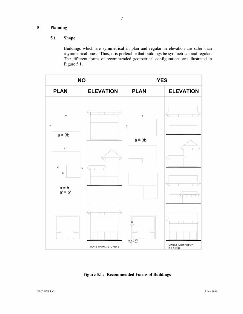
5 Planning 5.1 Shape Buildings which are symmetrical in plan and regular in elevation are safer than
asymmetrical ones. Thus, it is preferable that buildings be symmetrical and regular. The different forms of recommended geometrical configurations are illustrated in Figure 5.1.
Figure 5.1 : Recommended Forms of Buildings
NO YES
PLAN ELEVATIONELEVATIONPLAN
a
b
a = 3b
a
a'
b'
b
a = ba' = b'
MORE THAN 3 STOREYS MAXIMUM STOREYS 2 + ATTIC
a
b
a = 3b
W
min 2 W
NBC204V1.RV1 9 June 1994
8
5.2 Proportions The breadth to length ratio of a building shall not exceed 1:3. The breadth to length
ratio for any room or area enclosed by load-bearing walls inside the building shall also not exceed 1:3.
5.3 Storey Height The floor to floor height of an EB shall not be less than 1.8 m and not greater than
2.5 m. 5.4 Number of Storeys Earthen buildings shall be single-storeyed, but may have an additional attic floor.
The maximum height (floor to floor) of a building shall not exceed 8 times the wall thickness of the superstructure.
NBC204V1.RV1 9 June 1994
9
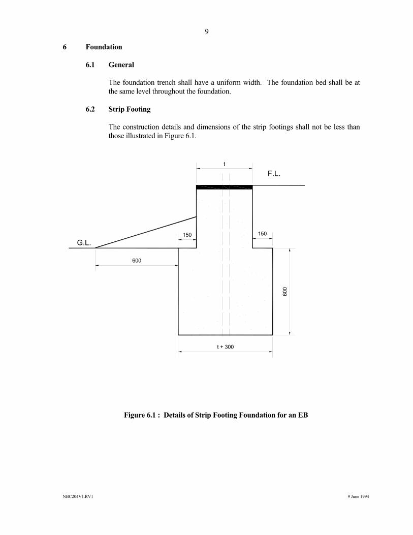
6 Foundation 6.1 General The foundation trench shall have a uniform width. The foundation bed shall be at
the same level throughout the foundation. 6.2 Strip Footing The construction details and dimensions of the strip footings shall not be less than
those illustrated in Figure 6.1.
Figure 6.1 : Details of Strip Footing Foundation for an EB
150 150
t + 300
600
t
600
F.L.
G.L.
NBC204V1.RV1 9 June 1994
10
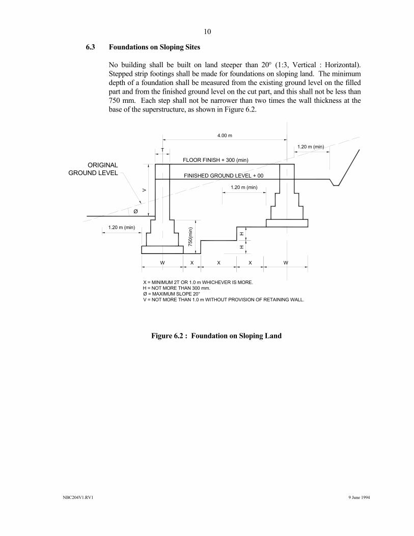
6.3 Foundations on Sloping Sites No building shall be built on land steeper than 20° (1:3, Vertical : Horizontal).
Stepped strip footings shall be made for foundations on sloping land. The minimum depth of a foundation shall be measured from the existing ground level on the filled part and from the finished ground level on the cut part, and this shall not be less than 750 mm. Each step shall not be narrower than two times the wall thickness at the base of the superstructure, as shown in Figure 6.2.
Figure 6.2 : Foundation on Sloping Land
W X X X W
750(
min
)1.20 m (min)
1.20 m (min)
1.20 m (min)
T
4.00 m
FLOOR FINISH + 300 (min)
FINISHED GROUND LEVEL + 00
HH
ORIGINALGROUND LEVEL
Ø
V
X = MINIMUM 2T OR 1.0 m WHICHEVER IS MORE.H = NOT MORE THAN 300 mm.Ø = MAXIMUM SLOPE 20°V = NOT MORE THAN 1.0 m WITHOUT PROVISION OF RETAINING WALL.
NBC204V1.RV1 9 June 1994
11
7 Walls 7.1 General Mud walls can be built successfully in a number of different ways. Among the
prevailing types, the following are recommended. These walls shall be constructed as detailed in respective sections. The minimum wall thickness for these wall types shall be as tabulated in Table 7.1.
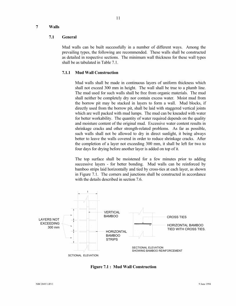
7.1.1 Mud Wall Construction Mud walls shall be made in continuous layers of uniform thickness which
shall not exceed 300 mm in height. The wall shall be true to a plumb line. The mud used for such walls shall be free from organic materials. The mud shall neither be completely dry nor contain excess water. Moist mud from the borrow pit may be stacked in layers to form a wall. Mud blocks, if directly used from the borrow pit, shall be laid with staggered vertical joints which are well packed with mud lumps. The mud can be kneaded with water for better workability. The quantity of water required depends on the quality and moisture content of the original mud. Excessive water content results in shrinkage cracks and other strength-related problems. As far as possible, such walls shall not be allowed to dry in direct sunlight, it being always better to leave the walls covered in order to reduce shrinkage cracks. After the completion of a layer not exceeding 300 mm, it shall be left for two to four days for drying before another layer is added on top of it.
The top surface shall be moistened for a few minutes prior to adding
successive layers - for better bonding. Mud walls can be reinforced by bamboo strips laid horizontally and tied by cross-ties at each layer, as shown in Figure 7.1. The corners and junctions shall be constructed in accordance with the details described in section 7.6.
Figure 7.1 : Mud Wall Construction
CROSS TIES
HORIZONTAL BAMBOOTIED WITH CROSS TIES.
VERTICALBAMBOO
HORIZONTALBAMBOOSTRIPS
t
LAYERS NOTEXCEEDING
300 mm
SCTIONAL ELEVATION
SECTIONAL ELEVATION SHOWING BAMBOO REINFORCEMENT
NBC204V1.RV1 9 June 1994
12
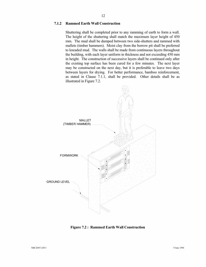
7.1.2 Rammed Earth Wall Construction Shuttering shall be completed prior to any ramming of earth to form a wall.
The height of the shuttering shall match the maximum layer height of 450 mm. The mud shall be dumped between two side-shutters and rammed with mallets (timber hammers). Moist clay from the borrow pit shall be preferred to kneaded mud. The walls shall be made from continuous layers throughout the building, with each layer uniform in thickness and not exceeding 450 mm in height. The construction of successive layers shall be continued only after the existing top surface has been cured for a few minutes. The next layer may be constructed on the next day, but it is preferable to leave two days between layers for drying. For better performance, bamboo reinforcement, as stated in Clause 7.1.1, shall be provided. Other details shall be as illustrated in Figure 7.2.
Figure 7.2 : Rammed Earth Wall Construction
MALLET(TIMBER HAMMER)
FORMWORK
GROUND LEVEL
NBC204V1.RV1 9 June 1994
13
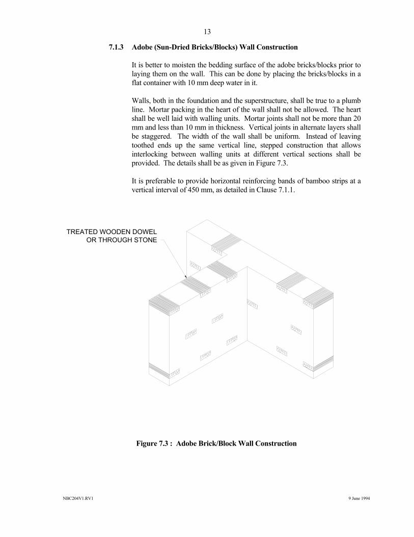
7.1.3 Adobe (Sun-Dried Bricks/Blocks) Wall Construction It is better to moisten the bedding surface of the adobe bricks/blocks prior to
laying them on the wall. This can be done by placing the bricks/blocks in a flat container with 10 mm deep water in it.
Walls, both in the foundation and the superstructure, shall be true to a plumb
line. Mortar packing in the heart of the wall shall not be allowed. The heart shall be well laid with walling units. Mortar joints shall not be more than 20 mm and less than 10 mm in thickness. Vertical joints in alternate layers shall be staggered. The width of the wall shall be uniform. Instead of leaving toothed ends up the same vertical line, stepped construction that allows interlocking between walling units at different vertical sections shall be provided. The details shall be as given in Figure 7.3.
It is preferable to provide horizontal reinforcing bands of bamboo strips at a
vertical interval of 450 mm, as detailed in Clause 7.1.1.
Figure 7.3 : Adobe Brick/Block Wall Construction
TREATED WOODEN DOWELOR THROUGH STONE
NBC204V1.RV1 9 June 1994
14
7.2 Wall Thickness The minimum thicknesses of different types of mud walls shall be as stated in Table
7.1.
WALL TYPE WALL THICKNESS
Mud Wall 600 - 450 mm *
Rammed-Earth Wall 400 - 450 mm
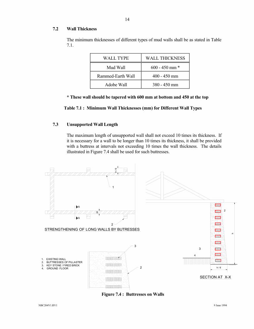
Adobe Wall 380 - 450 mm * These wall should be tapered with 600 mm at bottom and 450 at the top Table 7.1 : Minimum Wall Thicknesses (mm) for Different Wall Types 7.3 Unsupported Wall Length The maximum length of unsupported wall shall not exceed 10 times its thickness. If
it is necessary for a wall to be longer than 10 times its thickness, it shall be provided with a buttress at intervals not exceeding 10 times the wall thickness. The details illustrated in Figure 7.4 shall be used for such buttresses.
Figure 7.4 : Buttresses on Walls
SECTION AT X-X
STRENGTHENING OF LONG WALLS BY BUTRESSES
2
4
3
2
1
2
W
h
h / 6
h / 6
1. EXISTING WALL2. BUTTRESSES OF PILLASTER3. KEY STONE / FIRED BRICK4. GROUND FLOOR
3
A
A
NBC204V1.RV1 9 June 1994
15
7.4 Height of Walls The height to thickness ratio of a wall shall not be more than that stated in Table 7.2.
WALL TYPE RATIO
Mud Wall 8
Rammed Earth Wall 8
Adobe Wall 8 Table 7.2 : Maximum Thickness to Height Ratio of Walls 7.5 Protection of Mud Walls Damp rising from the ground to the superstructure, the penetration of rain water into
the wall from a leaking roof, and the splashing of water during rain, are the major problems which can make mud walls very weak. In order to make mud walls relatively stronger and durable, the following measures shall be adopted.
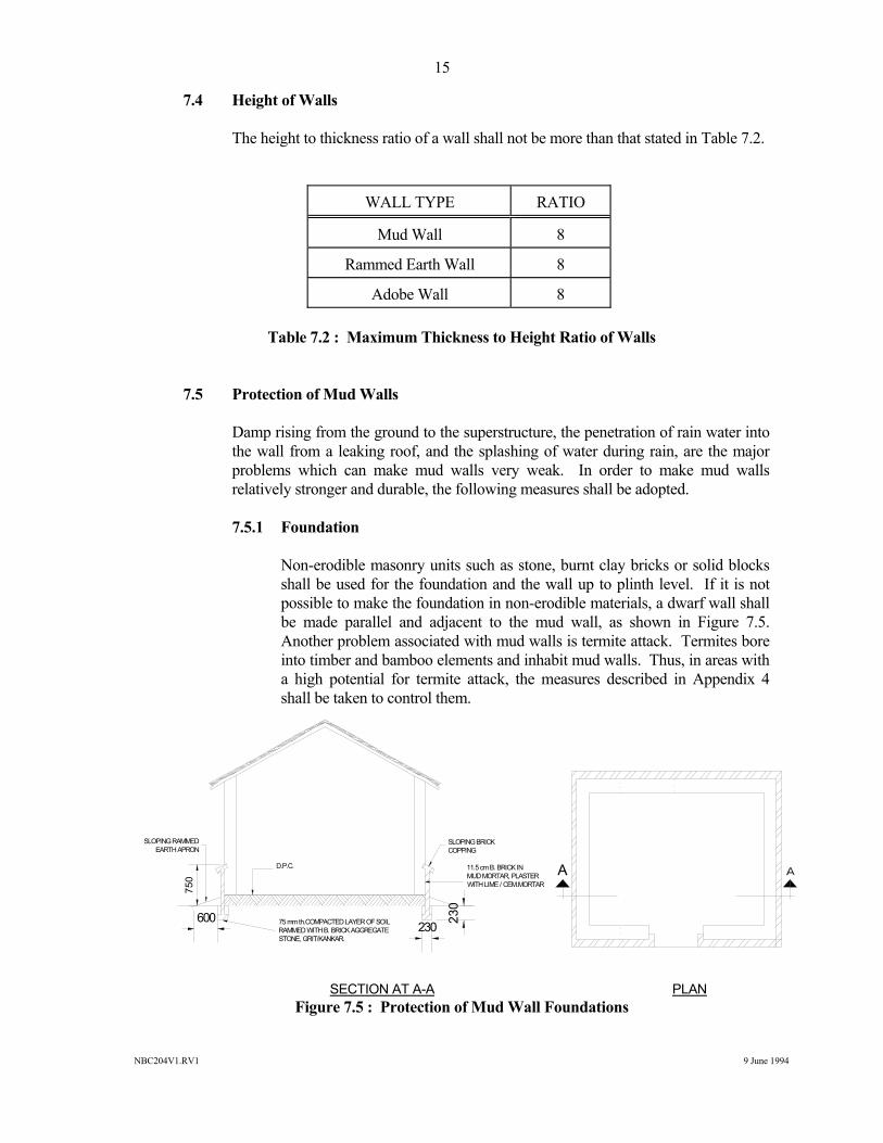
7.5.1 Foundation Non-erodible masonry units such as stone, burnt clay bricks or solid blocks
shall be used for the foundation and the wall up to plinth level. If it is not possible to make the foundation in non-erodible materials, a dwarf wall shall be made parallel and adjacent to the mud wall, as shown in Figure 7.5. Another problem associated with mud walls is termite attack. Termites bore into timber and bamboo elements and inhabit mud walls. Thus, in areas with a high potential for termite attack, the measures described in Appendix 4 shall be taken to control them.
SECTION AT A-A PLAN Figure 7.5 : Protection of Mud Wall Foundations
SLOPING BRICKCOPPING
D.P.C.
SLOPING RAMMEDEARTH APRON
750
75 mm th.COMPACTED LAYER OF SOILRAMMED WITH B. BRICK AGGREGATESTONE, GRIT/KANKAR.
11.5 cm B. BRICK IN MUD MORTAR, PLASTERWITH LIME / CEM.MORTAR
600 230
230
A
NBC204V1.RV1 9 June 1994
16
7.5.2 Damp Proof Course (DPC) A layer of DPC shall be laid as described in section 11.1. 7.5.3 Roof Projections The roof covering shall project at least 600 mm around all the exterior walls. 7.5.4 Non-Erodible Mud Plaster (NEM) All external wall surfaces shall be plastered with a layer of NEM. The
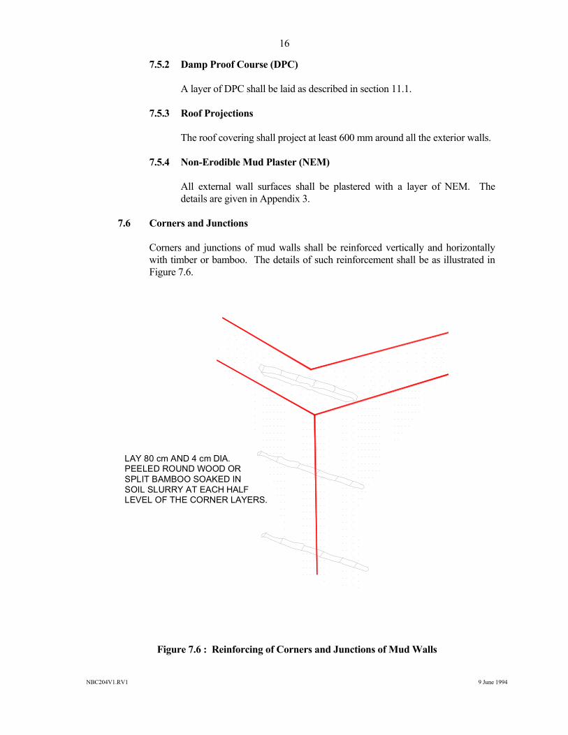
details are given in Appendix 3. 7.6 Corners and Junctions Corners and junctions of mud walls shall be reinforced vertically and horizontally
with timber or bamboo. The details of such reinforcement shall be as illustrated in Figure 7.6.
Figure 7.6 : Reinforcing of Corners and Junctions of Mud Walls
LAY 80 cm AND 4 cm DIA.PEELED ROUND WOOD OR SPLIT BAMBOO SOAKED IN SOIL SLURRY AT EACH HALF LEVEL OF THE CORNER LAYERS.
NBC204V1.RV1 9 June 1994
17
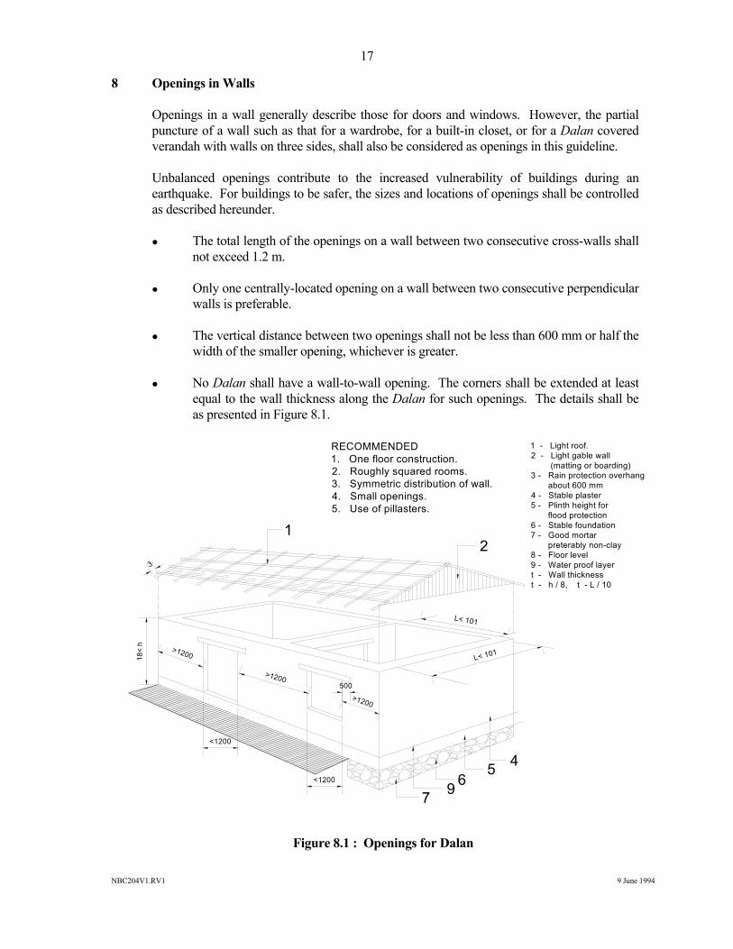
8 Openings in Walls Openings in a wall generally describe those for doors and windows. However, the partial
puncture of a wall such as that for a wardrobe, for a built-in closet, or for a Dalan covered verandah with walls on three sides, shall also be considered as openings in this guideline.
Unbalanced openings contribute to the increased vulnerability of buildings during an
earthquake. For buildings to be safer, the sizes and locations of openings shall be controlled as described hereunder.
The total length of the openings on a wall between two consecutive cross-walls shall
not exceed 1.2 m. Only one centrally-located opening on a wall between two consecutive perpendicular
walls is preferable. The vertical distance between two openings shall not be less than 600 mm or half the
width of the smaller opening, whichever is greater. No Dalan shall have a wall-to-wall opening. The corners shall be extended at least
equal to the wall thickness along the Dalan for such openings. The details shall be as presented in Figure 8.1.
Figure 8.1 : Openings for Dalan
RECOMMENDED1. One floor construction.2. Roughly squared rooms.3. Symmetric distribution of wall.4. Small openings.5. Use of pillasters.
1 - Light roof.2 - Light gable wall (matting or boarding)3 - Rain protection overhang about 600 mm4 - Stable plaster5 - Plinth height for flood protection6 - Stable foundation7 - Good mortar preterably non-clay8 - Floor level9 - Water proof layert - Wall thicknesst - h / 8, t - L / 10
21
45697
L< 101
L< 101>1200
>1200
>1200
500
3
18<
h
<1200
<1200
NBC204V1.RV1 9 June 1994
18
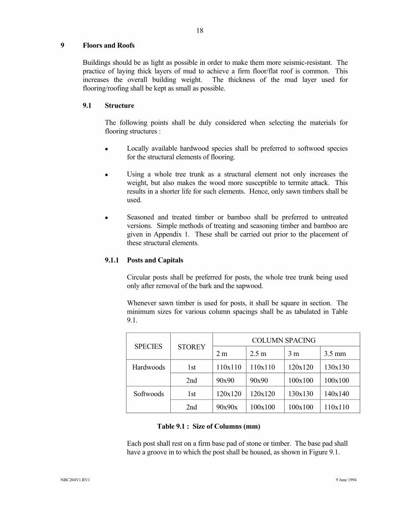
9 Floors and Roofs Buildings should be as light as possible in order to make them more seismic-resistant. The
practice of laying thick layers of mud to achieve a firm floor/flat roof is common. This increases the overall building weight. The thickness of the mud layer used for flooring/roofing shall be kept as small as possible.
9.1 Structure The following points shall be duly considered when selecting the materials for
flooring structures : Locally available hardwood species shall be preferred to softwood species
for the structural elements of flooring. Using a whole tree trunk as a structural element not only increases the
weight, but also makes the wood more susceptible to termite attack. This results in a shorter life for such elements. Hence, only sawn timbers shall be used.
Seasoned and treated timber or bamboo shall be preferred to untreated
versions. Simple methods of treating and seasoning timber and bamboo are given in Appendix 1. These shall be carried out prior to the placement of these structural elements.
9.1.1 Posts and Capitals Circular posts shall be preferred for posts, the whole tree trunk being used
only after removal of the bark and the sapwood. Whenever sawn timber is used for posts, it shall be square in section. The
minimum sizes for various column spacings shall be as tabulated in Table 9.1.
SPECIES STOREY COLUMN SPACING
2 m 2.5 m 3 m 3.5 mm
Hardwoods 1st 110x110 110x110 120x120 130x130
2nd 90x90 90x90 100x100 100x100
Softwoods 1st 120x120 120x120 130x130 140x140
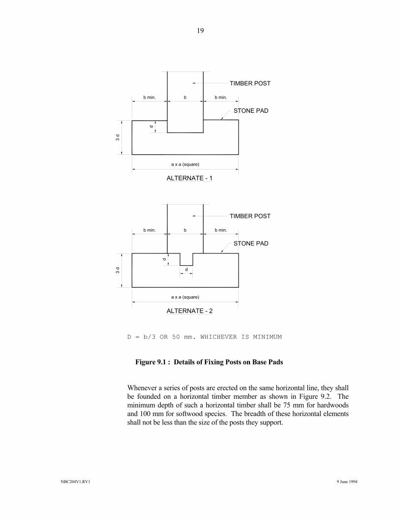
2nd 90x90x 100x100 100x100 110x110 Table 9.1 : Size of Columns (mm) Each post shall rest on a firm base pad of stone or timber. The base pad shall
have a groove in to which the post shall be housed, as shown in Figure 9.1.
NBC204V1.RV1 9 June 1994
19
D = b/3 OR 50 mm. WHICHEVER IS MINIMUM
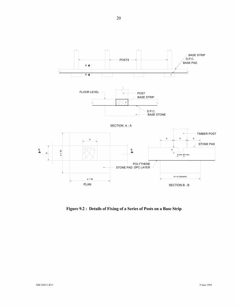
Figure 9.1 : Details of Fixing Posts on Base Pads Whenever a series of posts are erected on the same horizontal line, they shall
be founded on a horizontal timber member as shown in Figure 9.2. The minimum depth of such a horizontal timber shall be 75 mm for hardwoods and 100 mm for softwood species. The breadth of these horizontal elements shall not be less than the size of the posts they support.
b min. b b min.
d
a x a (square)
TIMBER POST
STONE PAD
ALTERNATE - 1
3 d
b min. b b min.
d
a x a (square)
TIMBER POST
STONE PAD
ALTERNATE - 2
3 d d
NBC204V1.RV1 9 June 1994
20
Figure 9.2 : Details of Fixing of a Series of Posts on a Base Strip
POSTSBASE PAD
D.P.C.BASE STRIP
POSTBASE STRIP
D.P.C.BASE STONE
FLOOR LEVEL
SECTION A - A
b b b
d
a x a (square)
TIMBER POST
STONE PAD
PLAN
d min 40 mm
POLYTHENEDPC LAYER
a = 3b
a =
3bb
b
STONE PAD
B B
A
A
SECTION B - B
NBC204V1.RV1 9 June 1994
21
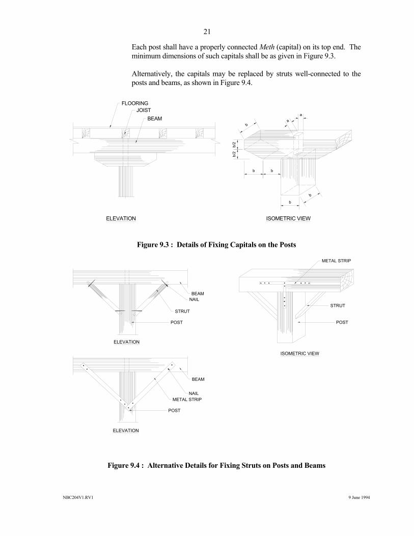
Each post shall have a properly connected Meth (capital) on its top end. The minimum dimensions of such capitals shall be as given in Figure 9.3.
Alternatively, the capitals may be replaced by struts well-connected to the
posts and beams, as shown in Figure 9.4.
Figure 9.3 : Details of Fixing Capitals on the Posts
Figure 9.4 : Alternative Details for Fixing Struts on Posts and Beams
FLOORINGJOIST
BEAM
b/2
b/2
ba
a
b
b
bb
ELEVATION ISOMETRIC VIEW
BEAMNAIL
STRUT
POST
BEAM
NAILMETAL STRIP
POST
METAL STRIP
STRUT
POST
ELEVATION
ELEVATION
ISOMETRIC VIEW
NBC204V1.RV1 9 June 1994
22
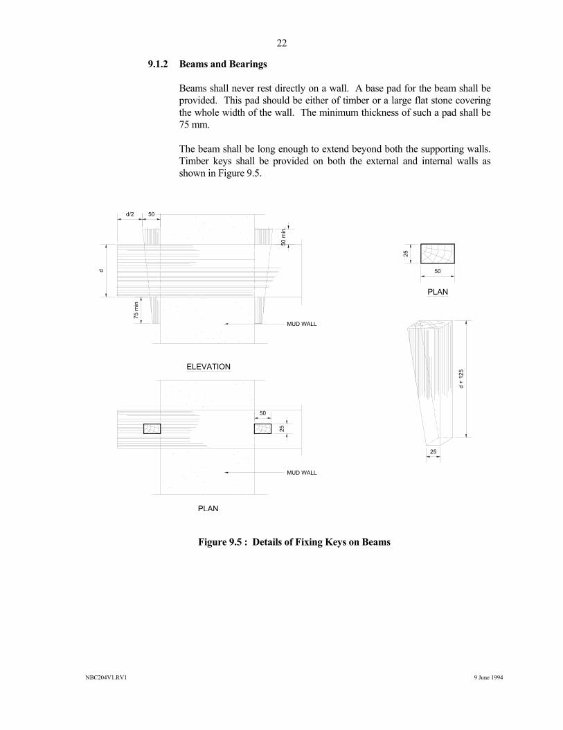
9.1.2 Beams and Bearings Beams shall never rest directly on a wall. A base pad for the beam shall be
provided. This pad should be either of timber or a large flat stone covering the whole width of the wall. The minimum thickness of such a pad shall be 75 mm.
The beam shall be long enough to extend beyond both the supporting walls.
Timber keys shall be provided on both the external and internal walls as shown in Figure 9.5.
Figure 9.5 : Details of Fixing Keys on Beams
25
50
25
d +
125
50
25
75 m
in
d
50d/2
50 m
in.
ELEVATION
PLAN
PLAN
MUD WALL
MUD WALL
NBC204V1.RV1 9 June 1994
23
The beams shall be rectangular in section and shall never be laid wider surface horizontal. The minimum dimensions of the beams for different spans shall be as tabulated in Table 9.2.
SPECIES
SPAN
2 m 2 to 2.5 m 2.5 to 3 m 3 to 3.5 m
Hardwood 190 220 240 270
SoftWood 230 270 310 340
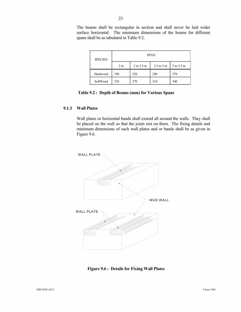
Table 9.2 : Depth of Beams (mm) for Various Spans 9.1.3 Wall Plates Wall plates or horizontal bands shall extend all around the walls. They shall
be placed on the wall so that the joists rest on them. The fixing details and minimum dimensions of such wall plates and or bands shall be as given in Figure 9.6.
Figure 9.6 : Details for Fixing Wall Plates
WALL PLATE
WALL PLATE
MUD WALL
NBC204V1.RV1 9 June 1994
24
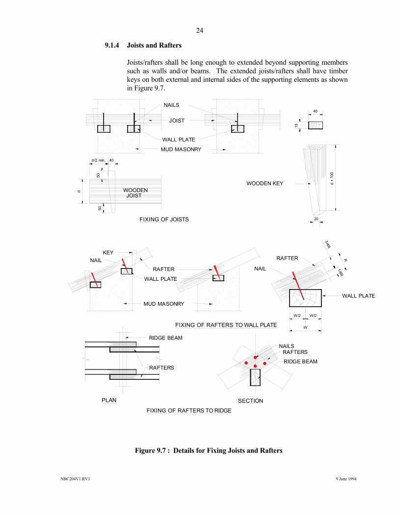
9.1.4 Joists and Rafters Joists/rafters shall be long enough to extended beyond supporting members
such as walls and/or beams. The extended joists/rafters shall have timber keys on both external and internal sides of the supporting elements as shown in Figure 9.7.
Figure 9.7 : Details for Fixing Joists and Rafters
NAILS
JOIST
WALL PLATE
MUD MASONRY
40
15
20
d +
100
5050
d
d/2 min. 40
WOODEN JOIST
FIXING OF JOISTS
KEYNAIL
RAFTER
WALL PLATE
MUD MASONRY
FIXING OF RAFTERS TO WALL PLATE
RAFTER
NAIL
WALL PLATE
W/2 W/2
3/4R
1/4RR
W
FIXING OF RAFTERS TO RIDGE
RIDGE BEAM
RAFTERS
NAILSRAFTERS
RIDGE BEAM
PLAN SECTION
WOODEN KEY
NBC204V1.RV1 9 June 1994
25
The joists/rafters shall be rectangular in section and shall never be laid with their wider surface horizontal. The minimum sizes of rafters for various spans shall be as tabulated in Table 9.3.
SPECIES
SPAN
1 m 1.5 m 2 m 2.5 m 3 m
Hardwood 100 100 100 120 130
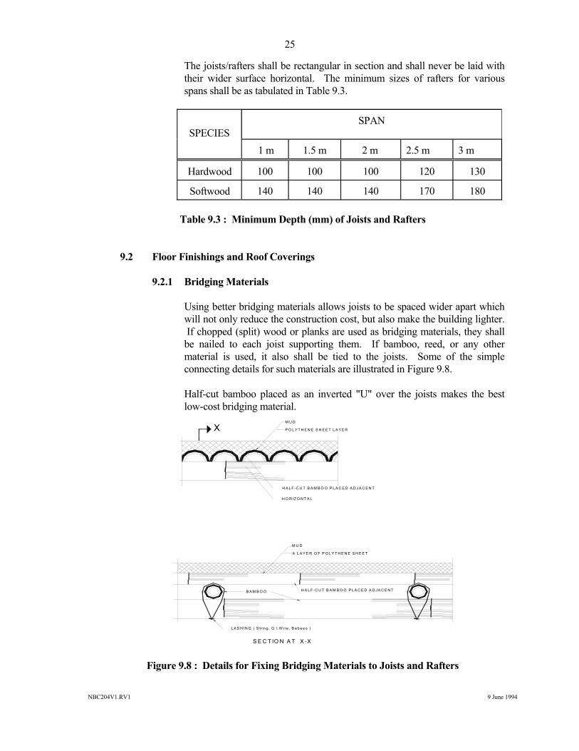
Softwood 140 140 140 170 180 Table 9.3 : Minimum Depth (mm) of Joists and Rafters 9.2 Floor Finishings and Roof Coverings 9.2.1 Bridging Materials Using better bridging materials allows joists to be spaced wider apart which
will not only reduce the construction cost, but also make the building lighter. If chopped (split) wood or planks are used as bridging materials, they shall be nailed to each joist supporting them. If bamboo, reed, or any other material is used, it also shall be tied to the joists. Some of the simple connecting details for such materials are illustrated in Figure 9.8.
Half-cut bamboo placed as an inverted "U" over the joists makes the best
low-cost bridging material.
Figure 9.8 : Details for Fixing Bridging Materials to Joists and Rafters
XM U D
P O L Y T H E N E S H E E T L A Y E R
H A L F -C U T B A M B O O P L A C E D A D J A C E N T
H O R IZ O N T A L
M U D
A L A Y E R O F P O L Y T H E N E S H E E T
B A M B O O H A L F -C U T B A M B O O P L A C E D A D J A C E N T
L A S H IN G ( S tr in g , G .I.W ire , B a b e e o )
S E C T IO N A T X -X
NBC204V1.RV1 9 June 1994
26
9.2.2 Floor Finishing It is preferable to use better bridging materials between the joists to achieve a
stiffer flooring. Timber planks and half-cut bamboo are examples of these. The fixing shall be carried out as illustrated in Figure 9.8.
The mud layers used for the floor base and the finish shall not be more than
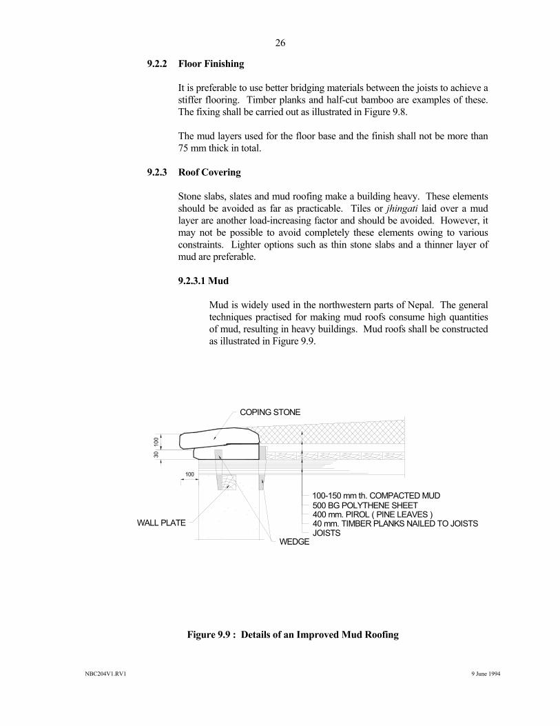
75 mm thick in total. 9.2.3 Roof Covering Stone slabs, slates and mud roofing make a building heavy. These elements
should be avoided as far as practicable. Tiles or jhingati laid over a mud layer are another load-increasing factor and should be avoided. However, it may not be possible to avoid completely these elements owing to various constraints. Lighter options such as thin stone slabs and a thinner layer of mud are preferable.
9.2.3.1 Mud Mud is widely used in the northwestern parts of Nepal. The general
techniques practised for making mud roofs consume high quantities of mud, resulting in heavy buildings. Mud roofs shall be constructed as illustrated in Figure 9.9.
Figure 9.9 : Details of an Improved Mud Roofing
COPING STONE
100-150 mm th. COMPACTED MUD500 BG POLYTHENE SHEET400 mm. PIROL ( PINE LEAVES )40 mm. TIMBER PLANKS NAILED TO JOISTSJOISTS
WEDGE
WALL PLATE
100
3010
0
NBC204V1.RV1 9 June 1994
27
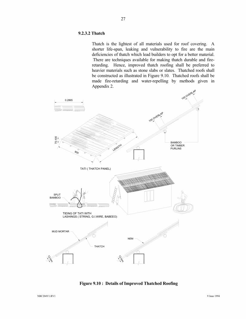
9.2.3.2 Thatch Thatch is the lightest of all materials used for roof covering. A
shorter life-span, leaking and vulnerability to fire are the main deficiencies of thatch which lead builders to opt for a better material. There are techniques available for making thatch durable and fire-retarding. Hence, improved thatch roofing shall be preferred to heavier materials such as stone slabs or slates. Thatched roofs shall be constructed as illustrated in Figure 9.10. Thatched roofs shall be made fire-retarding and water-repelling by methods given in Appendix 2.
Figure 9.10 : Details of Improved Thatched Roofing
LENGTH
900
75-1
00
0.2865
100 OVERLAP
100 OVERLAP
BAMBOOOR TIMBERPURLINS
SPLITBAMBOO
TIEING OF TATI WITHLASHINGS ( STRING, G.I.WIRE, BABEEO)
TATI ( THATCH PANEL)
THATCH
MUD MORTAR
NEM
12 mm
12 mm
NBC204V1.RV1 9 June 1994
28
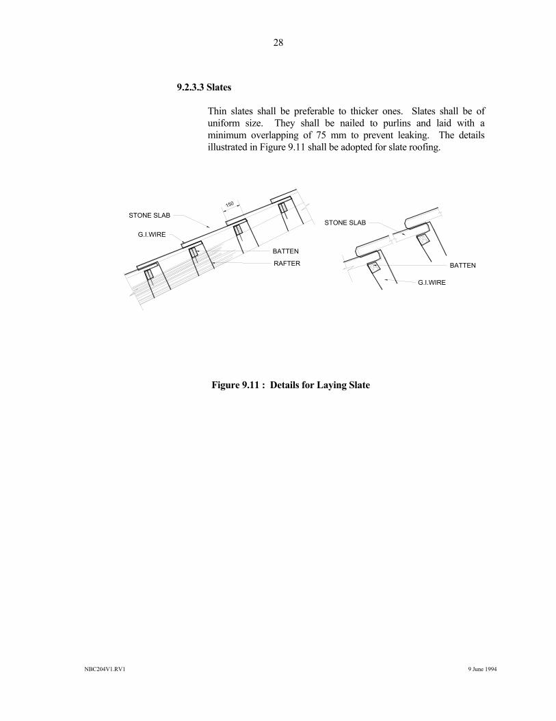
9.2.3.3 Slates Thin slates shall be preferable to thicker ones. Slates shall be of
uniform size. They shall be nailed to purlins and laid with a minimum overlapping of 75 mm to prevent leaking. The details illustrated in Figure 9.11 shall be adopted for slate roofing.
Figure 9.11 : Details for Laying Slate
BATTEN
RAFTER
STONE SLAB
G.I.WIRE
BATTEN
STONE SLAB
G.I.WIRE
150
NBC204V1.RV1 9 June 1994
29
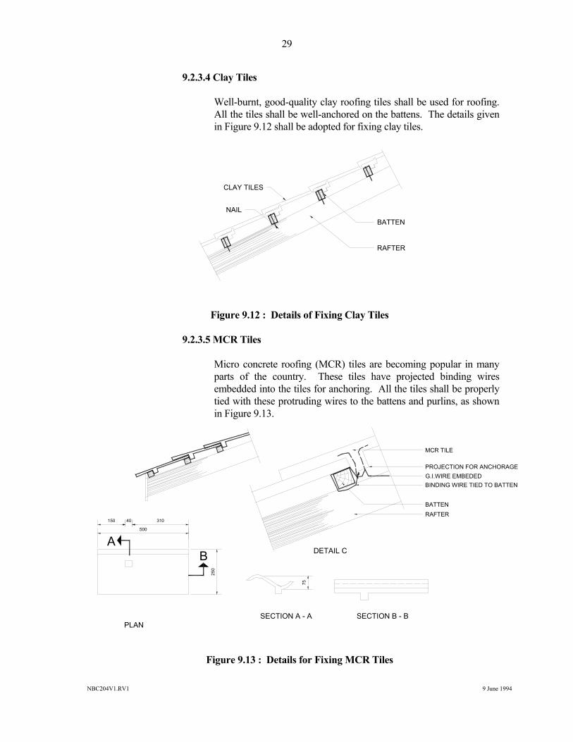
9.2.3.4 Clay Tiles Well-burnt, good-quality clay roofing tiles shall be used for roofing.
All the tiles shall be well-anchored on the battens. The details given in Figure 9.12 shall be adopted for fixing clay tiles.
Figure 9.12 : Details of Fixing Clay Tiles 9.2.3.5 MCR Tiles Micro concrete roofing (MCR) tiles are becoming popular in many
parts of the country. These tiles have projected binding wires embedded into the tiles for anchoring. All the tiles shall be properly tied with these protruding wires to the battens and purlins, as shown in Figure 9.13.
Figure 9.13 : Details for Fixing MCR Tiles
BATTEN
RAFTER
CLAY TILES
NAIL
MCR TILE
PROJECTION FOR ANCHORAGEG.I.WIRE EMBEDEDBINDING WIRE TIED TO BATTEN
BATTENRAFTER
PLANSECTION A - A SECTION B - B
DETAIL CA
B
500
150 40 310
250
75
NBC204V1.RV1 9 June 1994
30
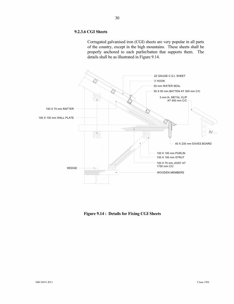
9.2.3.6 CGI Sheets Corrugated galvanised iron (CGI) sheets are very popular in all parts
of the country, except in the high mountains. These sheets shall be properly anchored to each purlin/batten that supports them. The details shall be as illustrated in Figure 9.14.
Figure 9.14 : Details for Fixing CGI Sheets
22 GAUGE C.G.I. SHEET
'J' HOOK
50 mm WATER SEAL
50 X 50 mm BATTEN AT 300 mm C/C
150 X 75 mm RAFTER
100 X 100 mm WALL PLATE
3 mm th. METAL CLIPAT 450 mm C/C
34°
40 X 230 mm EAVES BOARD
100 X 100 mm PURLIN100 X 100 mm STRUT
100 X 75 mm JOIST AT1750 mm C/C
WOODEN MEMBERS
WEDGE
NBC204V1.RV1 9 June 1994
31
9.3 Bamboo for Flooring and Roofing Only treated bamboo shall be used for structural elements. The bamboo shall be
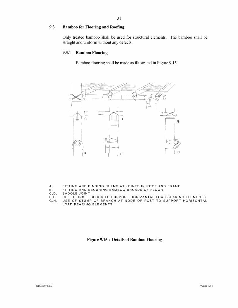
straight and uniform without any defects. 9.3.1 Bamboo Flooring Bamboo flooring shall be made as illustrated in Figure 9.15.
A , F I T T I N G A N D B I N D I N G C U L M S A T J O I N T S I N R O O F A N D F R A M E B , F I T T I N G A N D S E C U R I N G B A M B O O B R O A D S O F F L O O R C , D , S A D O L E J O I N T E , F , U S E O F I N S E T B L O C K T O S U P P O R T H O R I Z A N T A L L O A D S E A R I N G E L E M E N T S G , H , U S E O F S T U M P O F B R A N C H A T N O D E O F P O S T T O S U P P O R T H O R I Z O N T A L
L O A D B E A R I N G E L E M E N T S Figure 9.15 : Details of Bamboo Flooring
C EG
HFD
NBC204V1.RV1 9 June 1994
32
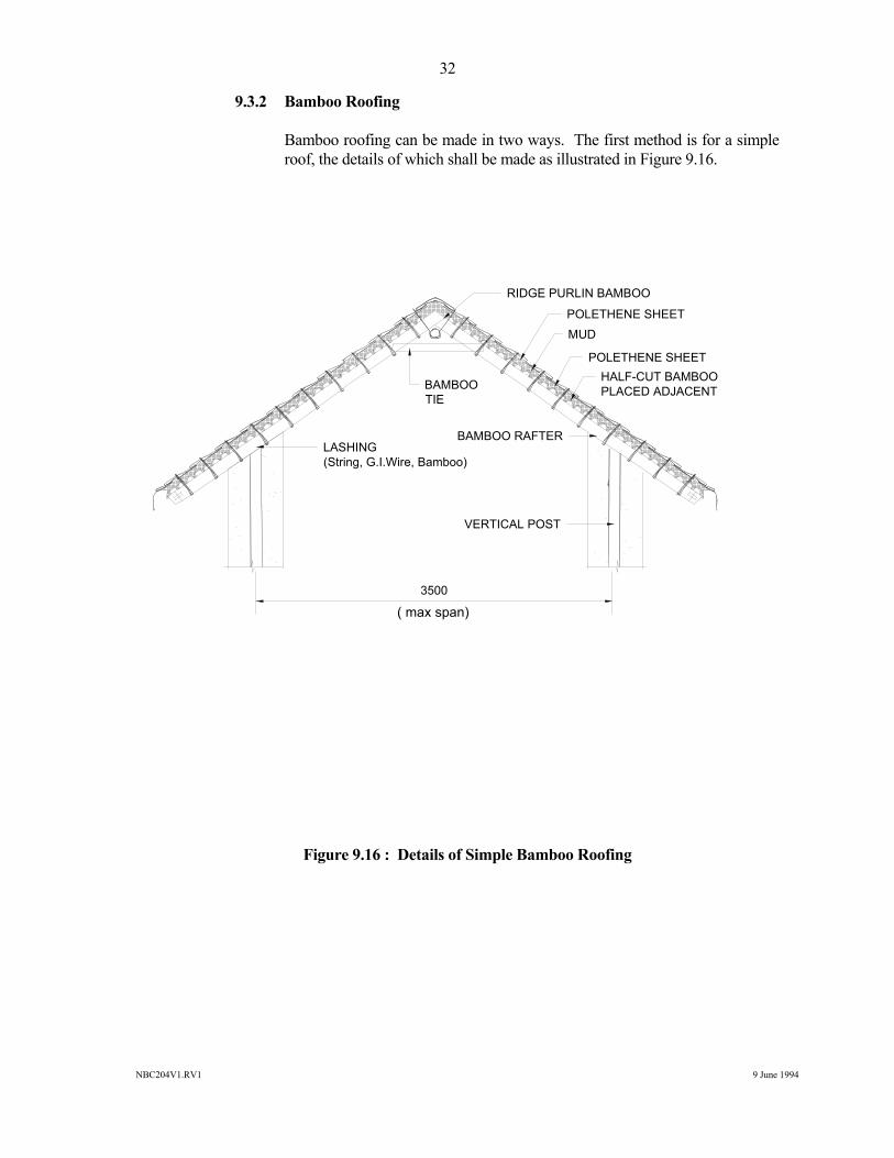
9.3.2 Bamboo Roofing Bamboo roofing can be made in two ways. The first method is for a simple
roof, the details of which shall be made as illustrated in Figure 9.16.
Figure 9.16 : Details of Simple Bamboo Roofing
3500
RIDGE PURLIN BAMBOO
POLETHENE SHEETMUD
POLETHENE SHEETHALF-CUT BAMBOOPLACED ADJACENTBAMBOO
TIE
BAMBOO RAFTERLASHING(String, G.I.Wire, Bamboo)
( max span)
VERTICAL POST
NBC204V1.RV1 9 June 1994
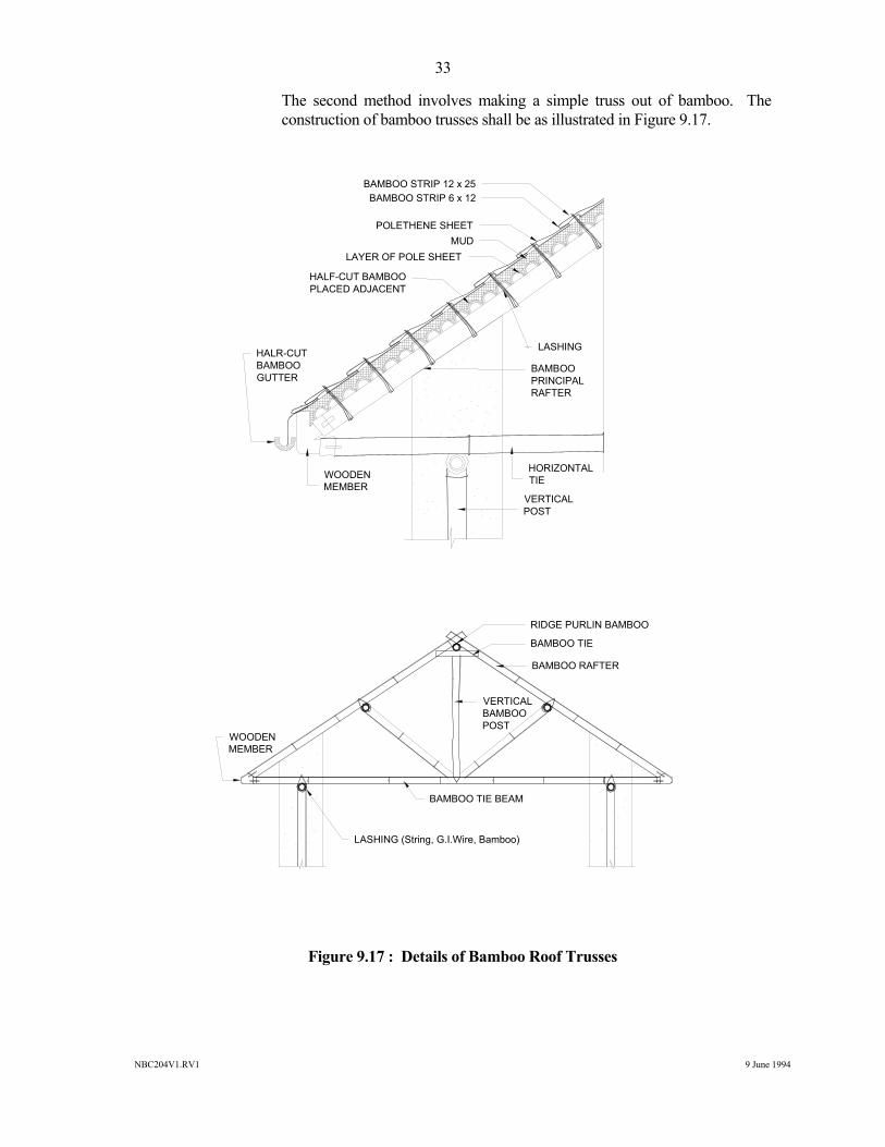
33
The second method involves making a simple truss out of bamboo. The construction of bamboo trusses shall be as illustrated in Figure 9.17.
Figure 9.17 : Details of Bamboo Roof Trusses
RIDGE PURLIN BAMBOO
BAMBOO TIE
BAMBOO RAFTER
VERTICALBAMBOO POST
BAMBOO TIE BEAM
LASHING (String, G.I.Wire, Bamboo)
WOODENMEMBER
BAMBOO STRIP 12 x 25BAMBOO STRIP 6 x 12
POLETHENE SHEETMUD
LAYER OF POLE SHEET
HALF-CUT BAMBOOPLACED ADJACENT
HALR-CUTBAMBOO GUTTER
LASHING
HORIZONTALTIEWOODEN
MEMBER
BAMBOO PRINCIPALRAFTER
VERTICALPOST
NBC204V1.RV1 9 June 1994
34
10 Seismic-Resistant Components
There are number of components which contribute to an enhanced safety against earthquake forces. These elements shall be incorporated in all buildings. The details are given hereunder.
10.1 Vertical Reinforcement
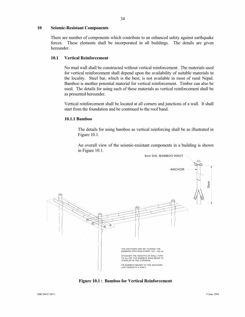
No mud wall shall be constructed without vertical reinforcement. The materials used for vertical reinforcement shall depend upon the availability of suitable materials in the locality. Steel bar, which is the best, is not available in most of rural Nepal. Bamboo is another potential material for vertical reinforcement. Timber can also be used. The details for using each of these materials as vertical reinforcement shall be as presented hereunder.
Vertical reinforcement shall be located at all corners and junctions of a wall. It shall start from the foundation and be continued to the roof band.
10.1.1 Bamboo The details for using bamboo as vertical reinforcing shall be as illustrated in
Figure 10.1. An overall view of the seismic-resistant components in a building is shown
in Figure 10.1.
Figure 10.1 : Bamboo for Vertical Reinforcement
THE ANCHORS ARE SET DURING THERAMMING PROCESS EVERY 100 - 120 cm
STAGGER THE HEIGHTS OF WALL TOPS TO ALLOW THE BAMBOO RING BEAM TOOVERLAP IN THE CORNERS.
TIE BAMBOO BEAMS TO THE ANCHORS JUST BENEATH A KNOT.
70cm
ANCHOR
6cm DIA. BAMBOO KNOT

NBC204V1.RV1 9 June 1994
35
10.1.2 Timber It is difficult to find a single stick of timber long enough to span between the
foundation and the roof. Dovetail joints shall be used to connect the different timbers to form a single unit. The details of providing such vertical reinforcement shall be as illustrated in Figure 10.2.
Figure 10.2 : Timber for Vertical Reinforcement
SECTION A - A
DOVE-TAIL JOINT AT B
METAL STRIP
HORIZONTALWOODEN MEMBER
METAL STRIP WOODENMEMBER
NAIL
B
NBC204V1.RV1 9 June 1994
36
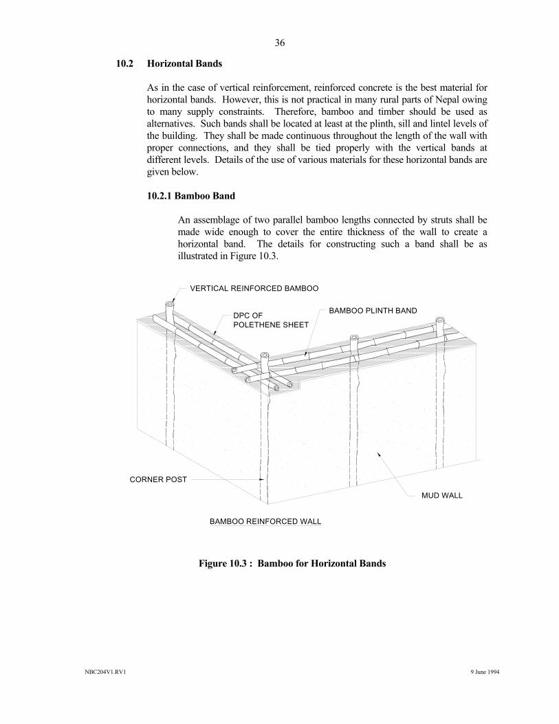
10.2 Horizontal Bands As in the case of vertical reinforcement, reinforced concrete is the best material for
horizontal bands. However, this is not practical in many rural parts of Nepal owing to many supply constraints. Therefore, bamboo and timber should be used as alternatives. Such bands shall be located at least at the plinth, sill and lintel levels of the building. They shall be made continuous throughout the length of the wall with proper connections, and they shall be tied properly with the vertical bands at different levels. Details of the use of various materials for these horizontal bands are given below.
10.2.1 Bamboo Band An assemblage of two parallel bamboo lengths connected by struts shall be
made wide enough to cover the entire thickness of the wall to create a horizontal band. The details for constructing such a band shall be as illustrated in Figure 10.3.
Figure 10.3 : Bamboo for Horizontal Bands
MUD WALL
BAMBOO PLINTH BANDDPC OF POLETHENE SHEET
VERTICAL REINFORCED BAMBOO
CORNER POST
BAMBOO REINFORCED WALL
NBC204V1.RV1 9 June 1994
37
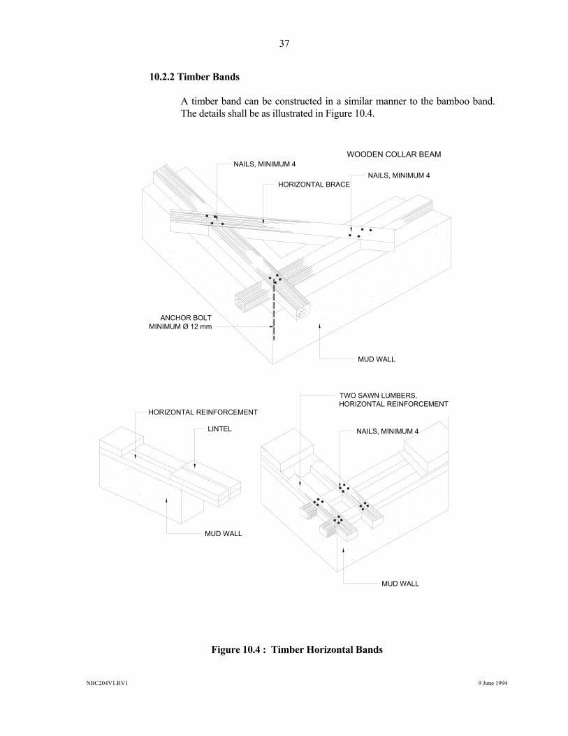
10.2.2 Timber Bands A timber band can be constructed in a similar manner to the bamboo band.
The details shall be as illustrated in Figure 10.4.
Figure 10.4 : Timber Horizontal Bands
NAILS, MINIMUM 4
HORIZONTAL BRACENAILS, MINIMUM 4
WOODEN COLLAR BEAM
ANCHOR BOLTMINIMUM Ø 12 mm
TWO SAWN LUMBERS,HORIZONTAL REINFORCEMENT
NAILS, MINIMUM 4
HORIZONTAL REINFORCEMENT
LINTEL
MUD WALL
MUD WALL
MUD WALL
NBC204V1.RV1 9 June 1994
38
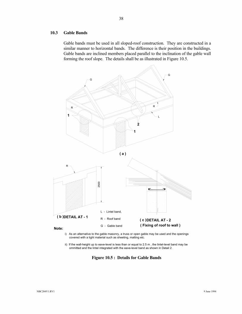
10.3 Gable Bands Gable bands must be used in all sloped-roof construction. They are constructed in a
similar manner to horizontal bands. The difference is their position in the buildings. Gable bands are inclined members placed parallel to the inclination of the gable wall forming the roof slope. The details shall be as illustrated in Figure 10.5.
Figure 10.5 : Details for Gable Bands
DETAIL AT - 1DETAIL AT - 2
( Fixing of roof to wall )
L - Lintel band,
R - Roof band
G - Gable band
i) As an alternative to the gable masonry, a truss or open gable may be used and the openings covered with a light material such as sheeting, matting etc.
ii) If the wall-height up to eave-level is less than or equal to 2.5 m , the lintel-level band may be ommitted and the lintel integrated with the eave-level band as shown in Detail 2.
Note:
2500
( a )
( b )( c )
L
G
G
RR
1
2
1
R
NBC204V1.RV1 9 June 1994
39
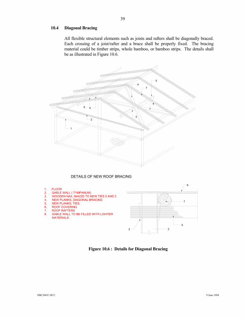
10.4 Diagonal Bracing All flexible structural elements such as joists and rafters shall be diagonally braced.
Each crossing of a joist/rafter and a brace shall be properly fixed. The bracing material could be timber strips, whole bamboo, or bamboo strips. The details shall be as illustrated in Figure 10.6.
Figure 10.6 : Details for Diagonal Bracing
1. FLOOR2. GABLE WALL ( TYMPANUM)3. WOODEN NAIL NAILED TO NEW TIES 5 AND 24. NEW PLANKS, DIAGONAL BRACING5. NEW PLANKS, TIES.6. ROOF COVERING 7. ROOF RAFTERS8. GABLE WALL TO BE FILLED WITH LIGHTER MATERIALS.
DETAILS OF NEW ROOF BRACING
6
7
523
1
23
7
4
54
5 4
NBC204V1.RV1 9 June 1994
40
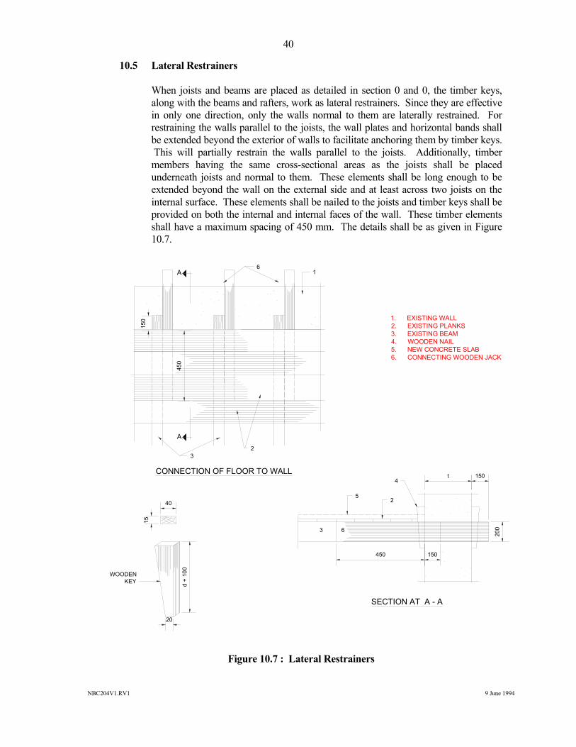
10.5 Lateral Restrainers When joists and beams are placed as detailed in section 0 and 0, the timber keys,
along with the beams and rafters, work as lateral restrainers. Since they are effective in only one direction, only the walls normal to them are laterally restrained. For restraining the walls parallel to the joists, the wall plates and horizontal bands shall be extended beyond the exterior of walls to facilitate anchoring them by timber keys. This will partially restrain the walls parallel to the joists. Additionally, timber members having the same cross-sectional areas as the joists shall be placed underneath joists and normal to them. These elements shall be long enough to be extended beyond the wall on the external side and at least across two joists on the internal surface. These elements shall be nailed to the joists and timber keys shall be provided on both the internal and internal faces of the wall. These timber elements shall have a maximum spacing of 450 mm. The details shall be as given in Figure 10.7.
Figure 10.7 : Lateral Restrainers
Figure 10.7 : Lateral Restrainers
t 150
200
2
4
3
40
15
20
d +
100
WOODENKEY
CONNECTION OF FLOOR TO WALL
SECTION AT A - A
1. EXISTING WALL2. EXISTING PLANKS3. EXISTING BEAM4. WOODEN NAIL5. NEW CONCRETE SLAB6. CONNECTING WOODEN JACK
61
150
450
23
6
450 150
5
A
A
NBC204V1.RV1 9 June 1994
41
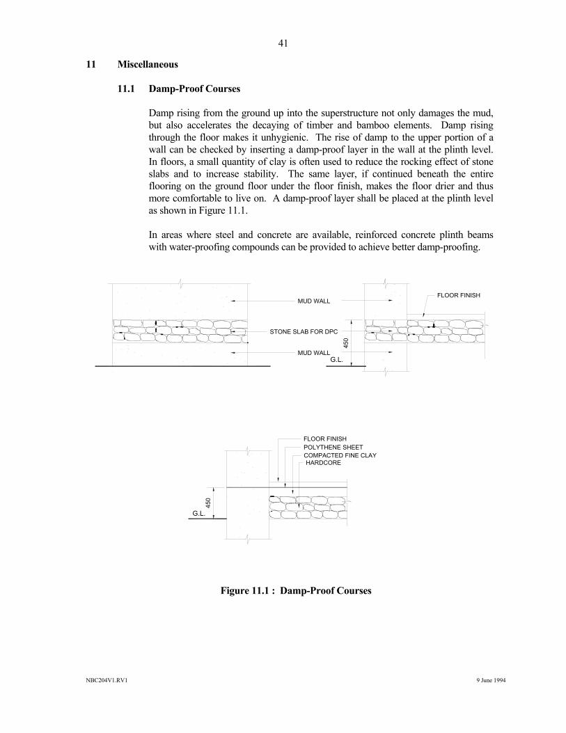
11 Miscellaneous 11.1 Damp-Proof Courses Damp rising from the ground up into the superstructure not only damages the mud,
but also accelerates the decaying of timber and bamboo elements. Damp rising through the floor makes it unhygienic. The rise of damp to the upper portion of a wall can be checked by inserting a damp-proof layer in the wall at the plinth level. In floors, a small quantity of clay is often used to reduce the rocking effect of stone slabs and to increase stability. The same layer, if continued beneath the entire flooring on the ground floor under the floor finish, makes the floor drier and thus more comfortable to live on. A damp-proof layer shall be placed at the plinth level as shown in Figure 11.1.
In areas where steel and concrete are available, reinforced concrete plinth beams
with water-proofing compounds can be provided to achieve better damp-proofing.
Figure 11.1 : Damp-Proof Courses
STONE SLAB FOR DPC
FLOOR FINISH
450
FLOOR FINISHPOLYTHENE SHEETCOMPACTED FINE CLAYHARDCORE
G.L.
450
G.L.
MUD WALL
MUD WALL
NBC204V1.RV1 9 June 1994
42
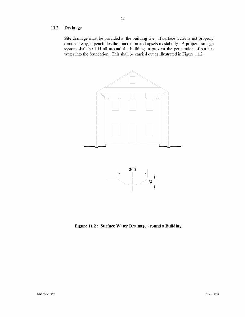
11.2 Drainage Site drainage must be provided at the building site. If surface water is not properly
drained away, it penetrates the foundation and upsets its stability. A proper drainage system shall be laid all around the building to prevent the penetration of surface water into the foundation. This shall be carried out as illustrated in Figure 11.2.
Figure 11.2 : Surface Water Drainage around a Building
300
50
NBC204V1.RV1 9 June 1994
A1-1
APPENDIX - 1 HARVESTING AND PRESERVING BAMBOO FOR CONSTRUCTION
1 Harvesting and Preservative Treatment 1.1 Harvesting
Bamboo should be three-years old before harvesting. Cutting selectively at a rate determined by ecological conditions, and removing only mature culms three-years old, is the most natural procedure for maintaining a grove in a condition of sustained yield.
Harvesting guidelines prepared by the Dehra Dun Forestry Institute (India) are
applicable for Nepal as the climate, the location of Dehra Dun and other conditions are similar to those in Nepal.
Correct harvesting is very essential because proper and systematic harvesting gives a
maximum life to cut bamboo for building component use. For some minor house components such as battens, the need for an additional preservative treatment may be prevented if systematic harvesting is carried out.
1.1.1 Harvesting Guidelines
• Do not cut any culm younger than three years, or in the rainy season, or from a flowering grove.
• No cuts shall be made lower than the second node or higher than
30 cm above ground. • Remove branches, culm tips, and all harvest trash. Debris obstructs
growth, encourages disease, and makes later harvesting more difficult.
• Leave leaves for mulch. Their 6 % silica content helps harden later
culms.
• A minimum of six mature culms should be left uncut in each clump of tropical species to sustain grove vitality and to insure a steady yield.
1.1.2 Clump Cure
Harvest bamboo at the beginning of the dry season; leave culms standing four to eight weeks in the groves, propped on stakes or rocks, with branches and leaves uncut so as to increase the evaporation surface and diminish insect entry points offered by freshly cut skin. This clump cure not only reduces starch content, which the bamboo beetles seek, but it also greatly decreases the tendency to crack and produces a pleasing uniform colour on the culms. These points can be remembered by the saying "Battle beetles better with clump-cured culms".
NBC204V1.RV1 9 June 1994
A1-2
1.2 Preservative Treatment Deterioration by insects, rot, fungi and fire is the most serious drawback to bamboo
as a building material. Traditional methods which are widely used to increase the durability of bamboo cost very little and can be carried out without any special equipment or technical knowledge. Harvesting and storing of bamboo in a proper way can increase the preservation of it considerably. The following methods are most appropriate for use in Nepal. Natural preservation as when bamboo is used in a smoky room is also suitable and cheap for some building components.
1.2.1 Water Leaching The most common treatment for protecting bamboo from Bostrichidae and
Lyetidae beetle attack is to leach out the starch, sugars and other water-soluble materials from the freshly-cut stems by submerging them in water. Removal of starch and sugar renders the bamboo unattractive to the beetles.
The bamboo must be completely under water, weighted down if necessary,
for periods ranging from three days to three months for freshly-cut bamboo and two weeks longer for partly-dry bamboo. Running water gives better results. Stagnant water sometimes leads to staining of the bamboo.
The susceptibility of bamboo to borer attacks depends on the species, its
starch content, age of the culm, felling season, and the physical properties of bamboo (Plank, 1950). But further studies indicate that starch content in bamboo is an important factor influencing the susceptibility to borer (Plank, 1950; 1951). The damage caused by borer has been found to be proportional to the starch content of the bamboo.
1.2.2 White Wash and Other Coatings A variety of coatings appropriate for Nepal, such as tar, lime wash, tar and
lime wash, and tar sprinkled with sand, may be used. However, these are effective only to the extent that they give a continuous coating at cut surfaces, exposed internodes, abrasions and slits.
1.2.3 Brushing, Swabbing, Spraying and Dipping These surface treatments are adopted for bamboo in storage or before it is
given impregnation treatments. Various chemicals are recommended for the protection of bamboo.
Dieldrin 0.05 percent, or Aldrin 0.15 percent, in aqueous emulsions give
almost complete protection against Dinoderus beetles for over a year. DDT, 7 to 10 % in kerosene oil and BHC, 0.2 percent, are even more effective. Spray application is recommended for stacks of bamboo.
NBC204V1.RV1 9 June 1994
A1-3
Dipping green or partly dry bamboo for 10 minutes in a 5 % solution of DDT
in fuel oil produces a highly-significant degree of control of the Dinoderus beetle for about 12 months. Soaking in the same solution for a longer period may result in protection for 24 to 30 months. For exposed bamboo where rainfall is likely, oil-borne insecticides should be prepared.
Except for treating large stocks, no expensive spraying equipment should be
required for the prophylactic treatment of bamboo. Hand-operated sprayers should normally be suitable for protection against fungi and borers. A five-minute dip is recommended in a solution containing 2 % borax and 1 % pentachlorophenol in which 1 % is dispersed.
Other methods are available, but these are more complex or costly and need
careful processes. They include : • Steeping, Boucherie process • Capping hot and cold bath process • Pressure treatment It should be noted that the water-leaching method seems to be the most
relevant bamboo preservation technique for the Nepalese situation. White wash and other coatings are also suitable as Nepalese people usually paint their houses annually during the Dasain festival.
1.3 Fire-Retarding Treatment Although not much work has been done on the protection of bamboo against fire, it
is possible to treat it with fire-retardant chemicals in the same way as wood. It is worthwhile to treat bamboo with the following fire-resistant cum antiseptic composition :
Ammonium Phosphate - 3 parts Boric Acid - 3 parts Copper Sulphate - 1 parts Zinc Chloride - 5 parts Sodium Dichromate - 3 parts Water - 100 parts A few drops of concentrated hydrochloric acid should be added to the solution to
dissolve the precipitated salts. 1.4 Storage Bamboo should be stacked horizontally on high, raised platforms, at least a foot
above ground for the prevention of termite attack. Bamboo should be stored so that
NBC204V1.RV1 9 June 1994
A1-4
all sides can be readily and regularly inspected. Remove or treat attacked culms. At the storage yard, bamboo is air-seasoned under cover for six to twelve weeks to increase strength and avoid cracking. Kiln-seasoning can do the same job in two to three weeks, though at the risk of splitting the outer membrane of several species if the seasoning is too rapid.
To reduce fungal attack, guard bamboo against wetting by rain or contact with soil.
Good ventilation and frequent inspection are important. The storage ground should be thoroughly inspected and cleaned before laying out the bamboo. All refuse and useless timber and bamboo should be removed.
Any termite-infested area of ground should be sprayed with a 4 % emulsion of DDT
or a 0.2 % emulsion of BHC or other suitable insecticide. Destroy termite colonies by breaking mounds open and pouring in insecticide. The ground should have good drainage facilities.
NBC204V1.RV1 9 June 1994
A2-1
APPENDIX - 2 FIRE-RETARDANT TREATMENT FOR THATCH 1 General Obviously, an exposed thatch surface is vulnerable to fire hazards. If this surface is
completely sealed with a thin, incombustible layer, it becomes fire-resistant. Since the roof has to be exposed to the atmosphere and subjected to rain, this thin layer has to be water-proof. Thus a layer of NEM plaster seems to be the simplest possible method.
1.1 Materials Required • Mud • Bhusa (chopped wheat or paddy straw) • 80/100 grade bitumen • Kerosene oil • Cow-dung • Firewood • Empty barrels for the melting and mixing of the bitumen 1.2 Method of Preparation The quantities of different materials given below will be sufficient for the fire-
retardant treatment of 100 m2 of roof area. 1.2.1 Preparation of Stabilised Mud Mortar • Collect three cubic metres of mud which contains 40 to 50 %
sand and 60 to 50 % of clay. • Mix 180 kg of chopped wheat or paddy straw with the mud. The
wheat straw has to be chopped in 20 mm lengths, whereas rice straw may be up to 50 mm in length. Old straw is preferred to fresh straw. Pour water over it and kneed until the straw and mud becomes an uniform paste.
• Kneed three to four times a day until the straw decomposes. The
mix should not be allowed to dry during this process. It takes generally seven days in summer and 14 days in winter to decompose the straw.
• The stabilised mud mortar is then ready. 1.2.2 Preparation of Cut-Back1 Bitumen (for NEM) • Collect 85 kg of bitumen and 17 litres of kerosene • Heat bitumen till it melts
NBC204V1.RV1 9 June 1994
A2-2
• Pour the melted bitumen into the kerosene and keep stirring till it is thoroughly mixed. (Never pour kerosene into bitumen.)
• The bitumen cut back1 for NEM is ready. 1.2.3 Preparation of NEM Mortar • Mix 90 kg of cut back1 bitumen for NEM with the stabilised mud
prepared as stated earlier. Kneed thoroughly to a uniform homogeneous mortar.
• The NEM is ready for application. 1.2.4 Preparation of Cut-Back2 Bitumen for Stabilised Mud Slurry • Collect 20 kg of bitumen and 2 litres of kerosene • Heat bitumen until it melts. • Pour the melted bitumen into the kerosene and keep stirring until
it is thoroughly mixed. (Never pour kerosene into bitumen.) • The cut-back2 bitumen is ready.
1.2.5 Preparation of Stabilised Mud Slurry1 for NEM • Mix 0.1 cubic metres of cow-dung and 0.1 cubic metres of mud.
Kneed thoroughly by adding water until the mixture becomes a thin paste.
• Add 12 kg of cut-back bitumen to this mixture and mix
thoroughly. • Make a uniform, homogeneous paste by constant stirring. • The stabilised mud slurry1 for NEM is now ready to use. 1.2.6 Preparation of Stabilised Mud Slurry2 for Fire-Retardant Plaster • Mix 0.1 cubic metres of cow-dung and 0.1 cubic metres of mud.
Kneed thoroughly by adding water until the mixture becomes a thin paste.
• Add 12 kg of cut-back bitumen to this mixture and mix
thoroughly. • Make a uniform, homogeneous paste by constant stirring. • Stabilised Mud Slurry2 for Fire Retardant Plaster is now ready to
use.
NBC204V1.RV1 9 June 1994
A2-3
1.3 Method of Application
1.3.1 Dressing of Roof Surface
• Update all the connections by tying properly and add or replace thatch if necessary.
• When the roof surface has been made uniform, it is ready to
receive the fire-retarding plaster.
1.3.2 Application of Stabilised Mud Plaster
• Start plastering with stabilised mud prepared as stated above. The plastering has to start from the top and proceed towards the bottom.
• The thickness of this plaster should be enough to make the
surface even and uniform such that it conceals all the bamboo strips and runners on top of the thatch covering.
• Allow this plaster to dry and crack for a day. • Fill the cracks next day. When the plaster is dry, some more
cracks may appear. Repeat the process until the whole wall surface becomes completely free of cracks.
1.3.3 Application of Stabilised Mud Slurry1
• Make sure that the roof surface is free of cracks. Fill the cracks with NEM if it already exists, and let it dry.
• Apply two coats of stabilised mud slurry1 over the stabilised mud
layer. The application can be either done by hand or with a brush.
1.3.4 Application of NEM plaster
• Start plastering with NEM, prepared as stated above, over the mud slurry1. The plastering has to be started from the top and continued towards the bottom.
• The average thickness of this plaster should be 12 mm. However, in the higher rain-fall areas, an additional 6 mm thickness of NEM plaster has to be applied.
• Allow this plaster to dry and crack for a day.
• Fill the cracks next day. When the plaster is dry, some more cracks may appear. Repeat the process until the whole wall surface becomes completely free of cracks.
NBC204V1.RV1 9 June 1994
A2-4
1.3.5 Application of Stabilised Mud Slurry2 • Make sure that the roof surface is free of cracks. Fill the cracks
with NEM if it already exists, and let it dry. • Apply two coats of stabilised mud slurry2 to the roof surface,
over the NEM plaster. The application can either be done by hand or with a brush.
• The roof is now fire-resistant. The application of the stabilised
mud slurry2 has to be repeated every two to three years for regular maintenance of the NEM plaster.
It is essential to render all the edges and corners of the roof with the
treatment for better resistance to fire. The ceiling has to be plastered with a layer of stabilised mud prepared as described above.
NBC204V1.RV1 9 June 1994
A3-1
APPENDIX - 3 PROTECTION OF MUD WALLS
1 Non-Erodible Mud Plaster (NEM)
Non-erodible mud plaster on wattle and daub, mud and sun-dried brick walls provides protection against erosion caused by splash-water, mainly during the rainy season.
1.1 Materials Required • Mud (1.5 m3). • Bhusa (chopped wheat or paddy straw) (90 kg). • 80/100 grade Bitumen (85 kg). • Kerosene oil (16 l). • Cow-dung (0.1 m3). • Fire wood. • Empty barrels for melting and mixing bitumen.
1.2 Method of Preparation
The quantities of different materials given hereunder will be sufficient for rendering a water-repellant treatment over 100 m2 of wall area.
1.2.1 Preparation of Stabilised Mud Mortar • Collect 1.4 m3 of mud which contains 40 to 50 % of sand, and 60 to
50 % of clay.
• Mix 90 kg of chopped wheat or paddy straw with the mud. The heat straw has to be chopped into 20 mm lengths, whereas rice straw may be up to 50 mm in length. Old straw is preferred to fresh straw. Pour on water and kneed until the straw and mud become a uniform paste.
• Kneed 3 to 4 times a day until the straw decomposes. The mix should not be allowed to dry during this process. It generally takes 7 days in summer and 14 days in winter to decompose the straw.
1.2.2 Preparation of Bitumen Cut-Back • The stabilised mud mortar is ready. • Collect 75 kg of bitumen and 15 litres of kerosene • Heat bitumen till it melts. • Pour the melted bitumen into the kerosene and keep stirring until it is
thoroughly mixed. (Never pour kerosene into bitumen.) • The bitumen cut-back is ready.
NBC204V1.RV1 9 June 1994
A3-2
1.2.3 Preparation of NEM mortar • Mix 90 kg of bitumen cut-back and stabilised mud prepared as stated
earlier. Kneed thoroughly to a uniform, homogeneous mortar. • The NEM is ready for application. 1.2.4 Preparation of Stabilised Mud Slurry • Mix 0.1 m3 of cow-dung and 0.1 m3 of mud, kneed thoroughly by
adding water until the mixture becomes a thin paste. • Add 12 kg of bitumen cut-back to this mixture and mix thoroughly. • Make it a uniform, homogeneous paste by constant stirring. • The stabilised slurry is now ready to use. 1.3 Method of Application 1.3.1 Dressing of Wall Surface • Fill all the put-log holes, cracks. • Scrape undulations, irregularities and all loose particles. • When the wall surface has been made uniform, it is ready to receive
the NEM plaster. 1.3.2 Application of NEM plaster • Moisten the wall surfaces by sprinkling water on them. • Start plastering with NEM prepared as stated above. The plastering
has to progress from the top towards the bottom. • The average thickness of this plaster should be 12 mm. However, in
the higher rain fall areas, an additional 6 mm thickness of NEM plaster needs to be applied.
• Allow this plaster to dry and crack for a day. • Fill cracks with NEM the next day. When the plaster is dry, some
more cracks may appear. Repeat the process until the whole wall surface becomes completely free of cracks.
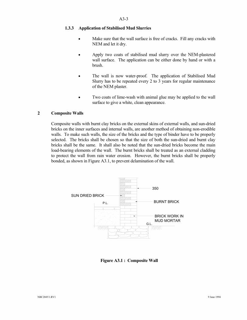
NBC204V1.RV1 9 June 1994
A3-3
1.3.3 Application of Stabilised Mud Slurries • Make sure that the wall surface is free of cracks. Fill any cracks with
NEM and let it dry. • Apply two coats of stabilised mud slurry over the NEM-plastered
wall surface. The application can be either done by hand or with a brush.
• The wall is now water-proof. The application of Stabilised Mud
Slurry has to be repeated every 2 to 3 years for regular maintenance of the NEM plaster.
• Two coats of lime-wash with animal glue may be applied to the wall
surface to give a white, clean appearance. 2 Composite Walls Composite walls with burnt clay bricks on the external skins of external walls, and sun-dried
bricks on the inner surfaces and internal walls, are another method of obtaining non-erodible walls. To make such walls, the size of the bricks and the type of binder have to be properly selected. The bricks shall be chosen so that the size of both the sun-dried and burnt clay bricks shall be the same. It shall also be noted that the sun-dried bricks become the main load-bearing elements of the wall. The burnt bricks shall be treated as an external cladding to protect the wall from rain water erosion. However, the burnt bricks shall be properly bonded, as shown in Figure A3.1, to prevent delamination of the wall.
Figure A3.1 : Composite Wall
SUN DRIED BRICK
350
BURNT BRICK
BRICK WORK IN MUD MORTAR
P.L.
G.L.
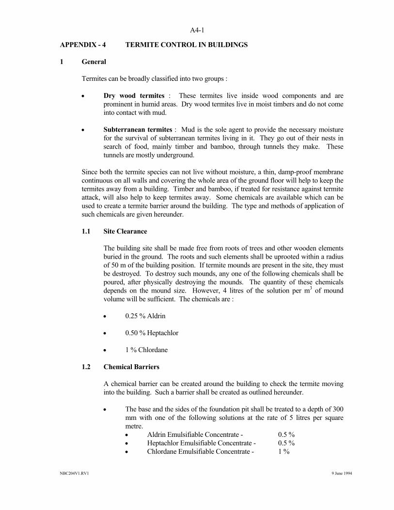
NBC204V1.RV1 9 June 1994
A4-1
APPENDIX - 4 TERMITE CONTROL IN BUILDINGS 1 General Termites can be broadly classified into two groups : • Dry wood termites : These termites live inside wood components and are
prominent in humid areas. Dry wood termites live in moist timbers and do not come into contact with mud.
• Subterranean termites : Mud is the sole agent to provide the necessary moisture
for the survival of subterranean termites living in it. They go out of their nests in search of food, mainly timber and bamboo, through tunnels they make. These tunnels are mostly underground.
Since both the termite species can not live without moisture, a thin, damp-proof membrane
continuous on all walls and covering the whole area of the ground floor will help to keep the termites away from a building. Timber and bamboo, if treated for resistance against termite attack, will also help to keep termites away. Some chemicals are available which can be used to create a termite barrier around the building. The type and methods of application of such chemicals are given hereunder.
1.1 Site Clearance The building site shall be made free from roots of trees and other wooden elements
buried in the ground. The roots and such elements shall be uprooted within a radius of 50 m of the building position. If termite mounds are present in the site, they must be destroyed. To destroy such mounds, any one of the following chemicals shall be poured, after physically destroying the mounds. The quantity of these chemicals depends on the mound size. However, 4 litres of the solution per m3 of mound volume will be sufficient. The chemicals are :
• 0.25 % Aldrin • 0.50 % Heptachlor • 1 % Chlordane 1.2 Chemical Barriers A chemical barrier can be created around the building to check the termite moving
into the building. Such a barrier shall be created as outlined hereunder. • The base and the sides of the foundation pit shall be treated to a depth of 300
mm with one of the following solutions at the rate of 5 litres per square metre.
• Aldrin Emulsifiable Concentrate - 0.5 % • Heptachlor Emulsifiable Concentrate - 0.5 % • Chlordane Emulsifiable Concentrate - 1 %
NBC204V1.RV1 9 June 1994
A4-2
• The materials for backfilling the foundation trench shall be treated with one
of the solutions. The treatment shall be carried out to a depth of 300 mm at a rate of 7.5 litres per square metre of the vertical surfaces of both the internal and external walls.
• The backfilling of the soil beneath the flooring sub-base has to be treated
with any one of the solutions at the rate of 5 litres per square metre of the flooring area for stopping the vertical movement of the termites.
1.3 Precautions • The chemicals shall be handled with care as all of them are toxic to men and
animals. Adequate precautions shall be taken to avoid contamination of food. Empty containers shall be disposed of properly, and any surplus shall be stored in labelled and airtight containers out of reach of children.
• Proper drainage and an apron shall be provided around the building to check
the excessive entry of moisture into the foundation.
NBC204V1.RV1 9 June 1994
A5-1
APPENDIX - 5 REFERENCE MATERIALS 1. "A Manual of Earthquake-Resistant Non-Engineered Construction", Indian Society of
Earthquake Technology, University of Roorkee, India. 2. "Protection of Educational Buildings Against Earthquakes", Professor AS Arya. 3. "School Construction Manual", HMG/UNCHS(Habitat), Kathmandu, Nepal. 4. "Live Better with Mud and Thatch", CBRI, Roorkee, India. 5. "Earthquake-Resistant Measures for Small Buildings", EAARRP, MHPP, HMG Nepal. 6. "Detailer's Manual for Small Buildings in Seismic Areas", Teddy Boen, Indonesia. 7. "Seismic Strength of Adobe Masonry", J Vargas, J Bairola, and M Blondet, Earthquake
Engineering Laboratory, Catholic University of Peru, Lima, and PK Meheta, Civil Engineering Laboratory, University of California, Berkeley, USA.
8. "Termite Control in Buildings", Building Research Note 50, CBRI, Roorkee.
NBC204V1.RV1 9 June 1994
A6-1
APPENDIX - 6 GLOSSARY The following terms used in this document are explained below : ABRASION means surface-wearing of a material due to friction with another material/materials in contact. ADOBE means sun-dried clay brick work with mud mortar. ADVISORY means suggestion (of better construction techniques, materials, etc) as opposed mandatory rules whose enforcement is assured by law. Non-observance of "Advisory" rules will be harmful to the owner. ANCHORED means fixed with devices like nails, bolts, hooks, etc., for ensuring better load transfer. ASYMMETRIC means the plan or section or view is not symmetrical. BAMBOO GROVES means a group/groups of bamboo trees at a particular place where they are growing naturally. BASE PAD means a member of a relatively stronger material provided at the base-end of a beam/post so as to transfer the load on to a wider area so that damage of the wall/support due to local point-load effect is avoided. BEARING means a supporting base material provided at the end of beams/joists to reduce the concentrated load effect. SEISMIC-RESISTANT CONSTRUCTION means construction in which earthquake-resistant structural and non-structural elements are incorporated. BOSTRICHIDAE means a kind of beetle (insect) that attacks the bamboo. BOX EFFECT means the effect by which an arrangement of individual elements, when connected together in a sound manner, can create a stronger structure than the sum of the individual element strengths. Various binding elements such as horizontal and vertical reinforcement, diagonal bracing and lateral restrainers, bands, etc. can bring about this effect. BRIDGING MATERIALS means materials used to span between two or more joists to form a floor and stabilise the individual joists. CGI SHEETS means corrugated galvanised iron sheets, mostly used as a roofing material. MUD WALL means a wall constructed with kneaded lumps of mud and compacted. CULM means a single unit of a bamboo tree DALAN means a one-side-open enclosure on the ground floor of a rural building, usually on the front face of the building.
NBC204V1.RV1 9 June 1994
A6-2
DAMP-PROOF COURSE means a relatively dense layer of water-proofing material provided below the plinth level in a wall or side of a building to prevent upwards migration of damp. DECIDUOUS TREES mean trees that lose their leaves annually, usually in autumn. DIAGONAL BRACING means the bracing of a wall or other members fixed diagonally at appropriate positions. DINODERUS BEETLE means a kind of beetle that attacks bamboo. EMBEDDED means placed firmly such that the bond is ensured. FIRE-RETARDANT means material or a process that decelerates the spread of fire. FLEXIBLE STRUCTURES means structures that do not have sufficient rigidity to resist deflection. FUNGAL ATTACK means a kind of infection (by fungi). GABLE BAND means a continuous band provided on the gable wall to hold it together during an earthquake. GEOLOGICAL FAULT LINES mean geological discontinuity lines on the ground surface that may cause earthquakes. HAZARDOUS means an area or situation that is susceptible to damage or destruction. HORIZONTAL BAND means a continuous member that may be of wood or bamboo or reinforced cement concrete. Provided at plinths, lintels and roof levels as required. INSECTICIDE means a chemical that kills insects. JHINGATI means traditional local burnt-clay tiles for roofing. Usually of small size. LAND SUBSIDENCE means relative upheaval or lowering of land with respect to the adjacent land. LATERAL RESTRAINERS means elements provided to restrain the walls in a horizontal direction (usually wooden keys) and to keep walls in position during horizontal loading. LATERALLY RESTRAINED means has lateral resistance to falling. LIQUEFACTION means a ground condition where the soil completely loses its load-bearing capacity and flows like liquid and any foundation sinks into the ground. It occurs mostly in saturated sand layers. LYETIDAE means a kind of beetle that attacks bamboo.
NBC204V1.RV1 9 June 1994
A6-3
MANDATORY means rules and regulations that are governed by a legal mandate and shall be observed. MARSHY means low-lying wet land. METH (CAPITAL) means a member of relatively larger surface area provided at supporting surfaces to distribute the load uniformly to the supporting posts. MICRO CONCRETE ROOFING (MCR) means roofing tiles having projected binding wires embedded into the tiles for anchoring. MUD SLURRY means mud mixed with water so as to make it a semi-liquid. NATURAL HAZARDS means hazards occurring naturally. For example, landslides, floods, earthquakes, etc. PLINTH means a floor raised from the natural ground level in a building to improve hygienic conditions in the building. PLUMB LINE means the vertical line shown by a plumb-bob (a weight hung on a length of string) PRESERVATIVE TREATMENT means the treatment of timber or bamboo to preserve it from insects and/or decay. PROPHYLACTIC means tending to prevent a disease or attack from harmful insects. RUPTURE LINES means the lines of failure of an object. SAPWOOD means a soft layer of wood between the bark and the inside hard core. SEISMIC SAFETY means safety against earthquake damage. SILL means the bottom level of an opening in a wall. SOFT-STOREY EFFECT means the poor structural behaviour of a storey in a building in which a particular lower storey has lesser rigidity than the storeys above it. STRUTS means cross-ties provided between two main elements to maintain their integrity and rigidity. SUPERSTRUCTURE means the structure above the plinth level such as walls, roofs, etc. SWABBING means the process of cleaning bamboo or timber with cotton cloths. SWAMP means soft, wet land in which foundations should be erected only after proper treatment. TERMITES means small insects, found chiefly in tropical areas, that are very destructive to timber (popularly called white ants).
NBC204V1.RV1 9 June 1994
A6-4
TERMITE INFESTED AREA means area where the termite are living, growing and cause damage to timber or bamboo where they are living. UN-STIFFENED means members that are not strengthened or has the less stiffness. UNBALANCED OPENINGS means the opening not being in proper places and storeys that may cause unbalanced stiffness or soft storey effect. UNSUPPORTED WALL LENGTH means the wall length without the buttresses or cross walls provided to reduce damage. VERNACULAR BUILDINGS means traditional buildings constructed in a locality. VERTICAL REINFORCEMENT means the vertical ductile element provided to increase the ductility of structure. VULNERABILITY means vulnerability is the ratio of expected loss to the maximum possible loss. VULNERABLE means a structure is said to be vulnerable if the damage is expected at a given hazard. WATER REPELLANT means materials that repel or show no affinity to water. WATER LOGGED means area saturated with water possessing lack of drainage. WATER LEACHING means process of treating timber or bamboo in water to raise its resistance to termites and beetles by leaching out starches ,sugar etc.