guidelines for installing a mr.steam steambath system
TRANSCRIPT

PUR10
0431
5/12
General Guidelines for Installingthe Mr.Steam® Steambath System
mr. steam
®www.mrsteam
.comEASTCOAST800-76-S
TEAM
WESTCOAST800-72-STEA
M

____________________________________________
For additional and important detailed Installation,
Operation and Maintenance information, it is strongly
recommended that reference be made to the Mr.Steam®
Residential Steambath Generator Manual PN 101289
or contact Mr.Steam® at 1-800-76-Steam,
[email protected] or visit www.mrsteam.com____________________________________________

2
Steamhead
Field InstalledWater Supply Line
Steam Generator
ControlCable
Field InstalledPower Supply
AutomaticDrain Valve
Field InstalledSteam Supply Pipe
In-ShowwerControl
Locating the Mr.Steam® Generator
Select a location as near as practical to the steam room.
Typical locations include: closet, vanity cabinet, heated attic or basement.
1 .Locate steambath generator within 50 feet of steam room. Note: The standardlength of the cable for connecting the control to the steam generator is 30 feet.The steam generator and control must be located accordingly. A 60 foot cable(PN 103990-60) is available as a special order part.
2.DO NOT install steambath generator inside steam room.
3.DO NOT install steambath generator outdoors or wherever environmentalconditions may affect the safety and/or performance of the generator.
4.DO NOT install steambath generator or plumbing lines inunheated attic or any locations where water could freeze.
5.DO NOT install steambath generator near flammable orcorrosive materials or chemicals such as gasoline, paint thinners,or the like. Installation in areas having high concentrations ofchlorine (such as pool equipment room) must be avoided.
6.Install steambath generator on a solid and level surface.Keyhole slots are provided for wall mounting. Insure thesteam generator is properly secured and level whenmounting with keyhole slots.
7.Install steambath generator in an upright position only.Install a pressure reducing valve to limit supply to 15-20 PSIG
8.Install anti-water hammer device as necessary.
9.Provide a minimum of (12) inches at both ends and top of the steamgenerator or as required for servicing.
For Illustrative purposes only. Consult with qualified designer,architect or contractor for steamroom construction details.

3
ON
OFF
Main ElectricalDisconnect Panel
240VPowerLine
1" Air Gap Indirect Drain System.Check local plumbing code forreceptor, trap and vent requirements.
Models MS 90E – MS 400E (single phase wiring shown)
Models MS Super 1E - 6E (single phase wiring shown)
Transformer
Liquid LevelControl Board
Water FeedSolenoid
Steam Outlet
Liquid LevelProbe
AutoFlush Plug &Play Connection
Contactor
PowerSupply
Knock-OutWater Feed
TransformerWater FeedSolenoid
Water Feed
Liquid Level Probe
AutoFlush Plug &Play Connection
FusesPower Blocks
Contactor
Power SupplyKnock-Out
SteamOutlet
* Super 1 is not internally fused
Liquid LevelControl Board
Field Power Supply Connection
________________________________________
TO AVOID EQUIPMENT DAMAGEDO NOT CONNECT POWER SUPPLYDIRECTLY TO ELEMENTS!!!________________________________________
NOTE: For illustrative purposes only.Consult with qualified licensed electricianfor electrical installation.
L1, L2, Groundto be field wired
Please refer to the wiringdiagram in the Mr.SteamInstallation Manual forcomplete wiring information.
For Illustrative purposes only. Consult with qualified designer,architect or contractor for steamroom construction details.

4
Water Feed Line(3⁄8" NPT)
Water Feed
1. Connect hot or cold water line. Hot waterline is preferable, however hot watershould not exceed 160˚ F.
2. Provide a shut off valve in the water supplyline upstream of the steambath generator.
3. Do not overheat inlet solenoid valve withsolder connections. Overheating willdamage parts.
4. Flush inlet water line thoroughly beforemaking connection to unit.
5. Strainer recommended upstream of feedwater connection.
6. For best performance water pressureshould be 15 to 20 PSIG. Reduce pressureas required if necessary.
7. Provide anti-water hammer device asrequired.
8. As required by local codes, install anapproved backflow preventer.
For Illustrative purposes only. Consult with qualified designer,architect or contractor for steamroom construction details.

5
Steam Generator
Steam OutletPipe
Union212˚ F RatePipe Insulation
PITCH UP OR DOWNBUT DO NOT CREATEVALLEYS OR TRAPS
Steam Outlet Pipe
Steam Outlet (1⁄2" NPT)1. Do not install any valve in steam line.Flow of steam must be unobstructed.
2. Use 1⁄2 -inch brass pipe or copper tubingfrom unit to steam head as permitted bycodes.
3. Insulate steam line using pipe insulationrated 250˚ F or higher.
4. Pitch steam line 1⁄4" per foot towardssteam head or steam generator to avoidvalleys and trapping of condensate.
NOTE: Running the steam line down andthen up will create a steam trap blockingthe flow of steam.NOTE: A 1.5" hole in the steamroomis required to mount the steamhead.
For Illustrative purposes only. Consult with qualified designer,architect or contractor for steamroom construction details.

6
Steam Generator
PITCH AS REQUIREDFOR GRAVITY DRAIN
Manual Drain ValveShown in Closed Position
Manual Drain Line
Drain (1⁄2" NPT)
NOTE: A drain valve is provided tofacilitate servicing. Provide a drain lineconnection from steambath generatordrain valve according to National andlocal Codes.Check local plumbing code for recep-tor, trap and vent requirements.Unit drains by gravity.
For Illustrative purposes only. Consult with qualified designer,architect or contractor for steamroom construction details.
7
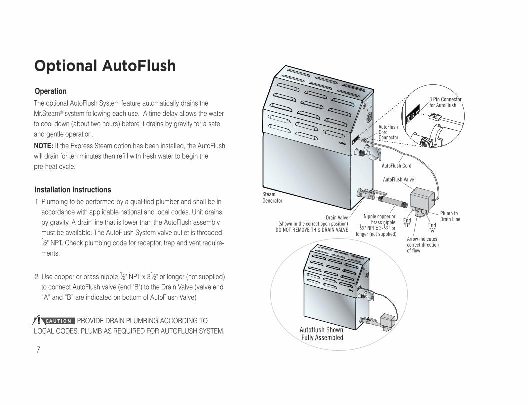
Autoflush ShownFully Assembled
Drain Valve(shown in the correct open position)
DO NOT REMOVE THIS DRAIN VALVE
Nipple copper orbrass nipple
1⁄2" NPT x 3-1⁄2" orlonger (not supplied)
SteamGenerator
AutoFlush Cord
AutoFlush Valve
AutoFlushCordConnector
Plumb toDrain LineEnd
"B" End"A"
Arrow indicatescorrect directionof flow
3 Pin Connectorfor AutoFlush
Optional AutoFlush
OperationThe optional AutoFlush System feature automatically drains theMr.Steam® system following each use. A time delay allows the waterto cool down (about two hours) before it drains by gravity for a safeand gentle operation.
NOTE: If the Express Steam option has been installed, the AutoFlushwill drain for ten minutes then refill with fresh water to begin thepre-heat cycle.
Installation Instructions1. Plumbing to be performed by a qualified plumber and shall be inaccordance with applicable national and local codes. Unit drainsby gravity. A drain line that is lower than the AutoFlush assemblymust be available. The AutoFlush System valve outlet is threaded1⁄2" NPT. Check plumbing code for receptor, trap and vent require-ments.
2. Use copper or brass nipple 1⁄2" NPT x 31⁄2" or longer (not supplied)to connect AutoFlush valve (end "B") to the Drain Valve (valve end“A” and “B” are indicated on bottom of AutoFlush Valve)
PROVIDE DRAIN PLUMBING ACCORDING TOLOCAL CODES. PLUMB AS REQUIRED FOR AUTOFLUSH SYSTEM.! CAUTION

8
Typical SteamGenerator Unit
3/4" Outlet
Drain Pan
Drip PanPN 103867
For Illustrative purposes only. Consult with qualified designer,architect or contractor for steamroom construction details.

9
Thermostat
Express SteamHeating Element
Express Steam(only available factory installed)
Suitable for all MS Models.
Express steam is equipped with a low powerheating element and thermostat to keep thewater in the tank warm enough to bring upsteam quicker. All express steam compo-nents and wiring are installed at the factory.
No additional wiring or plumbing is requiredby installers.

10
Transformer
Drain Line
Liquid LevelControl Board
Water FeedSolenoid
Water Inlet
Safety Valve
AutoFlushValve
(optional)
Stainless Steel TankHeating Element
Express SteamHeater (optional)
Access Cover
Liquid Level Probe
Plug and PlayConnection
Power Block
Power SupplyKnock-Out
Contactor
Steam Outlet
FusesPartsMS SUPER 2E shown

11
Secondary Unit
Primary Unit(unit the control
is connected to)
• Standard Tandem Cable forConnecting (2) Units PN 103904
• Optional Tandem Cable forConnections up to (5) UnitsPN 103917
Tandem Steam Generator Installation(MS Super 4E, 5E & 6E)
Refer to the Mr.Steam Installation manualfor additional installation information.
For Illustrative purposes only. Consult with qualified designer,architect or contractor for steamroom construction details.

12
Typical SteamGenerator Installation
Locate control where it willsense general room temperatureand NOT direct steam emissionfrom the steam head.Refer to the Mr.SteamInstallation manual foradditional controlinstallation information.
eTempo® and eTempo/Plus® Controls
For Illustrative purposes only. Consult with qualified designer,architect or contractor for steamroom construction details.
13
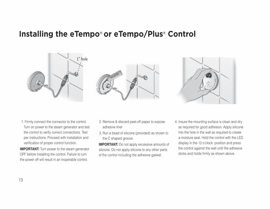
1" hole
Installing the eTempo® or eTempo/Plus® Control
1. Firmly connect the connector to the control.Turn on power to the steam generator and testthe control to verify correct connections. Testper instructions. Proceed with installation andverification of proper control function.
IMPORTANT: Turn power to the steam generatorOFF before installing the control. Failure to turnthe power off will result in an inoperable control.
2. Remove & discard peel-off paper to exposeadhesive liner
3. Run a bead of silicone (provided) as shown tothe C shaped groove.
IMPORTANT: Do not apply excessive amounts ofsilicone. Do not apply silicone to any other partsof the control including the adhesive gasket.
4. Insure the mounting surface is clean and dryas required for good adhesion. Apply siliconeinto the hole in the wall as required to createa moisture seal. Hold the control with the LEDdisplay in the 12 o'clock position and pressthe control against the wall until the adhesivesticks and holds firmly as shown above.

14
To eTempo oreTempo/Plus controls
Connecting the Control Cable to the Steam Generator
Route the control cable (providedwith the control) from the wall cutoutto the steam generator.
IMPORTANT: Do not strain, staple,pinch or otherwise damage the con-trol cable. Route cable as requiredto permit replacement.
The 30' (and optional 60') controlcable features identical Mini-Dinconnectors at both ends.
For Illustrative purposes only. Consult with qualified designer,architect or contractor for steamroom construction details.

15
MSTS Remote Temperature SensorLocate the RemoteTemperature Sensor (MSTS)where it will sense generalroom temperature and NOTdirect steam emission fromthe steam head.Refer to the Mr.SteamInstallation manual foradditional controlinstallation information.
Locating the eTempo® or eTempo/Plus®
Control Outside the Steam Roomby Using RemoteTemperature Sensor
For Illustrative purposes only. Consult with qualified designer,architect or contractor for steamroom construction details.

16
Steam Genie® Control
• Activate your steam shower fromanywhere in the home - Wirelessly
• Penetrates walls! Radio Frequencyactivated. Can be easily connectedwith any Mr.Steam® bath generator
• Adapts to standard Mr.Steam®
generator. No upgrade required
• Easy Plug & Play connection
• Can be used inside the shower
• Removable lanyard for convenience& storage “wearability”
17
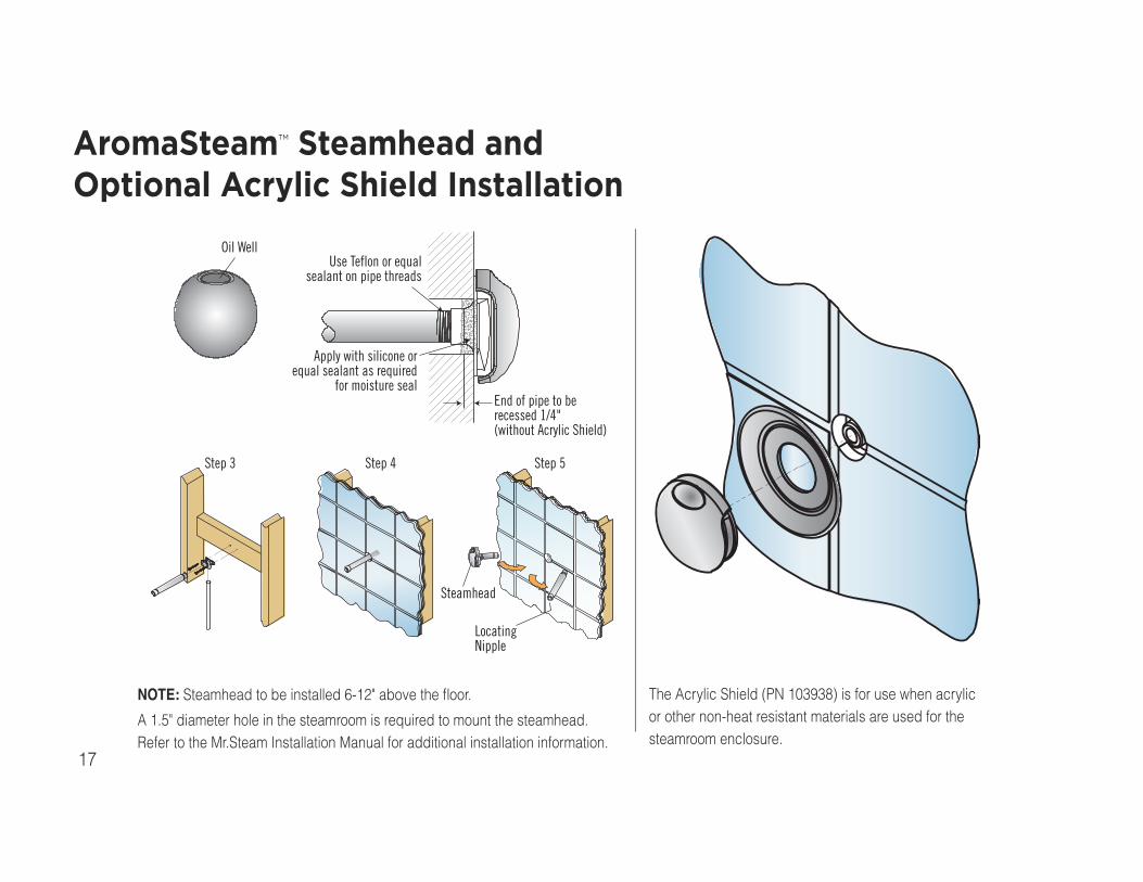
Use Teflon or equalsealant on pipe threads
Apply with silicone orequal sealant as required
for moisture sealEnd of pipe to berecessed 1/4"(without Acrylic Shield)
Oil Well
Steamhead
LocatingNipple
Step 3 Step 4 Step 5
AromaSteam™ Steamhead andOptional Acrylic Shield Installation
NOTE: Steamhead to be installed 6-12" above the floor.
A 1.5" diameter hole in the steamroom is required to mount the steamhead.Refer to the Mr.Steam Installation Manual for additional installation information.
The Acrylic Shield (PN 103938) is for use when acrylicor other non-heat resistant materials are used for thesteamroom enclosure.

18
Mr.Steam Essential Oilsmade from natural plantextracts. Packaged asindividual 10ml bottleswith integral dropper.
Using Essential Oils with theAromaSteam™ Steamhead
Enjoy essential oils by placing a drop or two, into yoursteamhead as shown in the illustration.
CAUTION: Use essential oils with caution. Essential oils are for externaluse only. Keep out of reach of children. Essential oils are highly concen-trated and are potent substances and should not be applied directly to theskin as they can be irritants. Use essential oils with caution.
CAUTION: Place the drops into the Mr.Steam AromaSteam steamheadwell prior to turning on the steambath. Do not place drops in a hot steamhead as SERIOUS INJURY CAN RESULT IF YOU DO NOT FOLLOW THISWARNING.
CAUTION: Start with one drop to gauge strength and suitability.Limit to a maximum of a few drops during a steambathing session.
CAUTION: Some people may find that the aroma makes them dizzy andthe user should exit the steam bath IMMEDIATELY. If skin irritation occursstop using the oils immediately. Remove any excess oil by washing in mildsoap and water. If ingested, rinse mouth with water. Administer water ormilk to dilute. Contact a physician immediately.
Tightly close containers when storing oils. Keep away from sourcesof ignition.

19
Typical Installation
Typical Mr.SteamSteam Generator
Cable to Steam Generator(Request Cable)
Pump Line Cord 120V(grounded receptacle required)
MountingBracket
AromaSteamSystem
Atomizer Nozzle
Pressure Hose
Steam Line
STEAM ROOM
UTILITYROOM
Min. distance 16"
Max. distance 36"
Steam head
Scent Container
The Demand Button remains unused(in the ON position) when the Aromasteam
system is operated by the eTempo/Plus control.
90˚ T
Max ht.6 ft.
AromaSteam™ SystemMS Aroma
Electronic Oil delivery system evenlyinfuses aroma into steam for an aro-matherapy experience. Complete within-shower control, oil container caddy,hoses, fittings and oil atomizer.AromaSteam Essential oils are availablein one-liter bottles. Not for use withacrylic or fiberglass rooms.
Locate the AromaSteam systemto monitor the consumption ofessential oils and for easy oilreplacement.
NOTE: CABLES SHOULD NOTCONTACT STEAM PIPE.
20
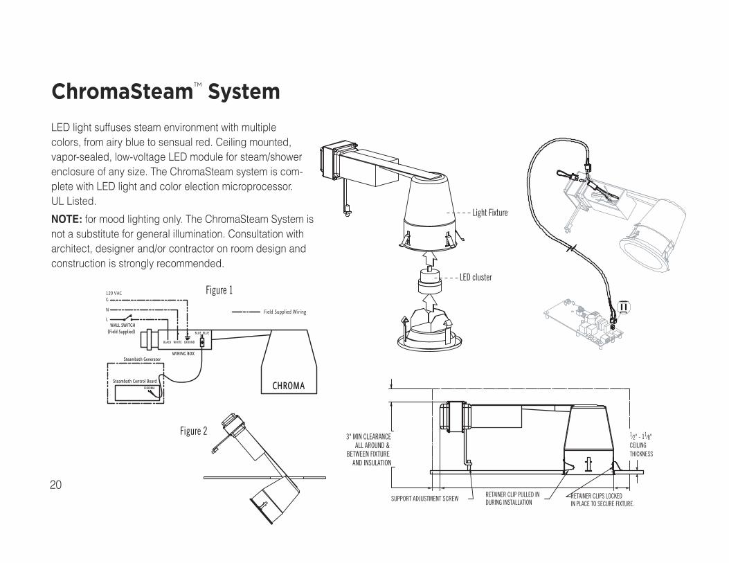
120 VACG
N
LField Supplied Wiring
BLACK WHITE GROUND
BLUE BLUE
WIRING BOX
WALL SWITCH(Field Supplied)
Steambath Generator
Steambath Control BoardCHROMA CHROMA
3" MIN CLEARANCEALL AROUND &
BETWEEN FIXTUREAND INSULATION
RETAINER CLIP PULLED INDURING INSTALLATION
RETAINER CLIPS LOCKEDIN PLACE TO SECURE FIXTURE.
SUPPORT ADJUSTMENT SCREW
1⁄2" - 11⁄8"CEILINGTHICKNESS
Figure 1
Figure 2
Light Fixture
LED cluster
ChromaSteam™ System
LED light suffuses steam environment with multiplecolors, from airy blue to sensual red. Ceiling mounted,vapor-sealed, low-voltage LED module for steam/showerenclosure of any size. The ChromaSteam system is com-plete with LED light and color election microprocessor.UL Listed.
NOTE: for mood lighting only. The ChromaSteam System isnot a substitute for general illumination. Consultation witharchitect, designer and/or contractor on room design andconstruction is strongly recommended.

21
Silicone RTV
Brackets shownrotated outafter installation
Speaker
Grill
Wall or Ceiling
Brackets
SpeakersMS-Speakers
Two 51⁄2" diameter flush-mount two-way speakersfor steam/shower use, polypropylene cones,ABS frames with grills. Suitable for almostany source of audio input. Rated 60W peakpower 8 ohms impedance with 1" tweeter forfull range sound.Use only CL2 or CL3 UL listedwires to connect speakers to audio source.
22
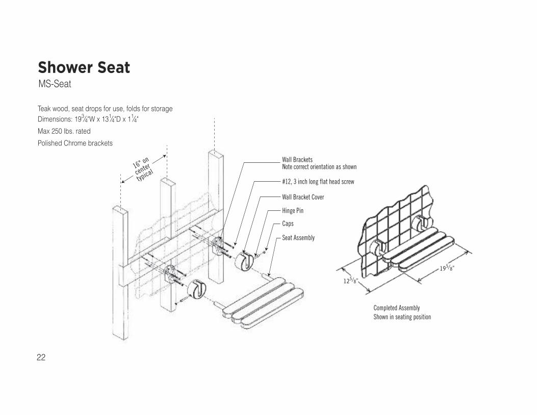
125/8"
195/8"
Completed AssemblyShown in seating position
16" on
center
typical
Wall BracketsNote correct orientation as shown
#12, 3 inch long flat head screw
Wall Bracket Cover
Hinge Pin
Caps
Seat Assembly
Shower SeatMS-Seat
Teak wood, seat drops for use, folds for storageDimensions: 193⁄4"W x 131⁄4"D x 11⁄4"Max 250 lbs. rated
Polished Chrome brackets

mr.steam®
Sussman-Automatic Corporation® [email protected] www.mrsteam.com
43-20 34th Street, Long Island City, NY 11101 Tel: 718 937 4500 Fax: 718 472 3256
9410 S. La Cienega Blvd. Inglewood CA 90301 Tel: 310 216 6565 Fax: 310 216 2944
2012 © Sussman-Automatic CorporationMR. STEAM and des., A LIFETIME OF PLEASURE, AROMAFLO, AUTOFLUSH, CLEAN STEAM...EVERY TIME, CLUB THERAPY, DIGITAL 1, eTEMPO,eTEMPO/PLUS, FROM BATHROOM TO SPA, MAKING WELLNESS a WAY of LIFE, MUSIC THERAPY, STEAM ON DEMAND, STEAM@HOME, STEAMGENIE, STEAMTHERAPY, and SUSSMAN are registered trademarks of Sussman-Automatic Corporation. AROMASTEAM, BUTLER PACKAGE, CHRO-MASTEAM, EXPRESS STEAM, HOME WIZARD, STEAM STOP, THE INTELLIGENT STEAMBATH and VALET PACKAGE are trademarks ofSussman-Automatic Corporation. PUR 100431 5/12
mr .
stea
m®
Fan us on Follow us onFacebook Twitter