guidelines for passive protection on roads by vehicle ... · the. guidelines for passive protection...
TRANSCRIPT

Research Society for Roads and Transportation Traffic Management Work Group
Guidelines for passive protection on roads by vehicle restraint systems
RPS
Issue 2009

Traffic Management Work Group Working Committee: Protective equipment
Manager:
RDir. Dipl.-Phys. Uwe Ellmers, Bergisch Gladbach (from 2006)
previously: BDir. a. D. Dipl.-Ing. Rainer Kehrein, Wiesbaden
(until 2006)
previously: Ltd. RDir. a. D. Dr-Ing, Wolfgang Schulte, Bergisch
Gladbach (until 1998)
Staff:
BDir. Dipl--lng. Michael Antenbrink, Wiesbaden
Dr.-Ing. Michael M. Baier, Aachen
Dipl.vlng. Ulrich Bergerhausen, Bergisch Gladbach
BDir. Dipl.Tng. Herwig Cross-beame, Offenburg
Dipl.-Ing. Heike Jung, Kroft
Dr.-Ing. Christian Kammel, Siegen
Dr.-Ing. Thorsten Kathmann, Aachen
Dipl.vlng. Janine Kubler, Bergisch Gladbach
Univ-Prof. Dr.-Ing. Reinhold Maier, Dresden
Dipl-Ing. (FH) Arno Putzschke, Koblenz
Dipl.-Ing. Ulrich Sasse, Kaln
Mr. Joachim Schellhorn, Rosrath
Mr. Dieter Schonauer, Montabaur
BAss. Dipl-Ing. Hans Dieter Schonborn, Koblenz
Dipl-Ing. Wolfgang Schuler, Siegen
Dipl-Ing. Kay-Uwe Thorn, Limburg
Mr. Karl Urlberger, Aschaffenburg
Dipl-Ing. Bernd Vasmer, Gelsenkirchen
Dr.-Ing. AlfVollpracht, Kaln
Also cooperated in the preparation of the RPS until their retirement:
Dipl-Ing. Stefan Buitkamp, Berlin
RDir. Dr.-Ing. Arnold Hemmert-Halswick, Bergisch Gladbach
Dipl-Ing, Horst Hulsen , Koln
Dr-Ing. Ralf Klo ckner, Bergisch Gladbach
Mr. Alois Reiff, Kroft
RDir. Dipl.vlng. Reinhold Seliger, Bergisch Gladbach
Introduction
The. Guidelines for passive protection on roads by vehicle restraint systems (RPS), 2009 Edition, replace the
guidelines for passive protection on roads "(RPS), 1989 edition, including the supplements of 1996.

Table of Contents
Page
1
Content, purpose, scope 5
2 General requirements for vehicle restraint systems 6
2.1 General 6
2.2 Protective equipment 6
2.3 Expansion and compression joints 6
2.4 Start and end construction 7
2.5 Crash cushion 7
2.6 Environment of vehicle restraint systems 8
2.7 Accessory components 8
2.8 Two-wheeler protection 8
3
Application criteria and application-specific requirements
9
3.1 General 9
3.2 Lane departure probability 9
3.3 Outer edge of roadway 9
3.3.1 Protective equipment 10
3.3.1.1 Critical distances 10
3.3.1.2 Containment levels 12
3.3.1.3 Ranges 12
3.3.1.4 Lengths 12
3.3.1.5 Discontinuances 15
3.3.2 Expansion and compression joints 17
3.3.3 Start and end construction 17
3.3.4 Crash cushion 18
3.4 Median and shoulder strip 18
3.4.1 Protective equipment 18
3.4.1.1 Containment levels 19
3.4.1.2 Ranges 19
3.4.2 Expansion and compression joints 19
3.4.3 Start and end construction 19
3.4.4 Crash cushion 19
3.5 Edges of bridges and supporting walls 21
3.5.1 Protective equipment 21
3.5.1.1 Containment levels 21
3.5.1.2 Ranges 21
3.5.1.3 Lengths 21
3.5.1.4 Areas of flexible expansion joints 22
3.5.2 Expansion and compression joints 22
3.5.3 Start and end construction 23
3.5.4 Crash cushion 23
3.6 Median and shoulder strips on bridges 23
3.6.1 Protective equipment 23

3.6.1.1 Containment levels 23
3.6.1.2 Ranges 23
3.6.1.3 Areas of flexible expansion joints 23
3.6.2 Expansion and compression joints 23
3.7 Walls and portals 24
3.7.1 Protective equipment 24
3.7.2 Expansion and compression joints 24
3.7.3 Start and end construction 24
3.7.4 Crash cushion 24
Appendices 25
Appendix 1: Technical regulations 25
Appendix 2: Terms 26
Appendix 3: Excerpts from DIN EN 1317 27

1 Content, Purpose, Scope
(1) Various structures are combined under the term vehicle restraint systems according to European terminology and are defined as follows according to DIN EN 1317:
− Protective equipment,
− Start and end construction,
− Expansion and compression joints,
− Crash cushion,
(2) Vehicle restraint systems should keep the consequences of accidents as low as possible. They are considered
− For the protection of uninvolved persons or vulnerable areas alongside the road or for oncoming traffic on two-lane roads,
− to protect the vehicle occupants against serious consequences as a result of leaving the roadway, for example, due to a crash or before an impact with dangerous obstacles near the roadway.
(3) The guidelines apply1)
a) for securing hazardous areas in the new construction, reconstruction or expansion of roads-
2
b) for the protection of the new hazard areas on existing roads
2);
c) for areas of existing roads2)
where vehicle restraint systems are replaced due to aging. Repairs on vehicles based on transports do not represent a replacement in this sense;
d) for sections of existing roads-2
with frequent accidents according to criteria of the 3-year map according to the instruction leaflet for the evaluation of road accidents, part 1: managing and analyzing accident type cards, in which the accident type “leaving the roadway” predominates;
e) (e) for sections of existing roads-2
, on which other accident abnormalities exist.
(4) The guidelines for costruction measures on roads in water reserves (RiStWag) apply additionally for protective equipment. If the guidelines there arrive at different determinations in reference to the use or the performance requirements of vehicle restraint systems, the guidelines with the higher requirements apply.
(5) These guidelines apply only for permanently used vehicle restraint systems. The temporary use of vehicle restraint systems, such as work areas, is governed by the “Additional technical contractual specifications and guidelines for protective operations on roads" (ZTV-SA).
(6) Additional regulations for the use of vehicle restraint systems are compiled in Appendix 1.
1)
"The obligations under Directive 98/34 by the European Parliament and Council of June 22, 1998 concerning an information process based on the standards and regulations for Information Society (ABI. EG No. L 204 page 37), amended by guideline of the European Parliament and Council of July 20, 1998 (ABI, EG No. L 217 page 18), have been met.
2) This also applies for bridges within the course of
roads.

2 General requirements for vehicle restraint systems
2.1 General
(1) Vehicle restraint systems must meet the requirements of DIN EN 1317 “Restraint systems on roads". The compliance with the requirements must be verified by presenting the relevant test reports.
(2) Products from other member countries of the European Community, Turkey or an EFTA country, which is a contract party of the EEA agreement, will be treated equally, if it has been properly manufactured and/or marketed and the safety level for traffic safety, health and usability has been verifiably permanently achieved according to the Directive.
(3) Vehicle restraint systems are divided according to performance categories based on the test results according to DIN EN 1317. The definition of these performance classifications results from the respective parts of DIN EN 1317 (Fig. 1).
2.2 Protective equipment
(1) The performance capability of protective equipment is divided according to three essential criteria according to DIN EN 1317-2
− Containment level,
− Effective area class,
− Impact severity level.
(2) The required containment level depends on the application criteria and is regulated in section 3.
(3) The maximum effective area class depends on the local situation and is regulated in section 3.
(4) Impact severity level A represents a lower impact for the occupants of a vehicle that leaves the roadway than impact severity level B and is preferred in comparable situations. A protective device of impact severity level C, which represents the highest impact for the vehicle occupants, can be selected at especially dangerous areas, on which containing a vehicle leaving the roadway (such as a heavy transport vehicle) is of primary importance.
(5) The input quantities of the required lengths of protective equipment are also treated in section 3. 2.3 Expansion and compression joints
(1) Expansion and compression joints must be arranged where protective equipment of various designs and/or function must be properly connected.
(2) The capacity of expansion and compression joints is differentiated according to the criteria of
− Containment level,
− Effective area class,
− Impact severity level.
(3) The containment level of expansion and compression joints depends on the containment levels of the protective equipment to be connected. The required containment levels are defined in table 1.
Fig. 1: Definition of the performance levels according to DIN EN 1317 Table 1: Containment levels of expansion and compression joints
Vehicle restraint systems
Protective devices Start and end
construction Expansion and
compression joints
Performance classes
according to part 2 of
DIN EN 1317:
Containment level
Effective area class
Impact severity level
Performance classes
according to part 4 DIN V
ENV 1317:
Performance class
Class of the vehicle
impact area
Class of the permanent
lateral deflection
Impact severity level
Performance classes
according to part 4
DIN V ENV 1317:
Containment level
Effective area class
Impact severity class
Performance classes
according to part 3 of
DIN EN 1317:
Performance
class/speed class
Class of the
permanent lateral
deflection
Class of the return
Crash cushion

From protective equipment of containment level
For protective equipment of containment level
N2 H1 H2 H4b
N2 N2 N2 H1 H2 H1 N2 H1 H1 H2 H2 H1 H1 H2 H2 H4b H2 H2 H2 H4b
(4) The selection of the maximum effective area class of an expansion and compression joint depends on the local situation.
(5) The impact severity level of an expansion and compression joint should not be greater than one of the levels of the protective equipment to be connected.
(6) Connections on structures (such as abutments) are considered to be expansion and compression joints.
2.4 Start and end construction
(1) Start and end construction and subsequent protective equipment must be connected functionally so that the functional properties (including tie back effect of the protective equipment, passive safety of the start and end construction, stress transfer) do not alternately affect each other. The functional properties of the thus connected systems must be verified by the manufacturer of the start and end construction, based on the start and end construction.
(2) The capacity of start and end constructions is differentiated according to DIN V ENV 1317-4 under the criteria of
− Performance class ,
− Class of the vehicle impact area,
− Class of the permanent lateral deflection,
− Impact severity level
(see Tables A 5 to A 7).
(3) The requirements for the performance classes of start and end construction result from table 2.
Table 2: Performance classes for start and end construction according to DIN V ENV 1317-4
Type of road Performance class
single lane at least P2 A
two lanes at least P2 U A: Start and end constructionacting in both directions of travel U: Start and end construction acting in the direction of travel
(4) The class of the vehicle impact area (minimum requirement class Z4) and the class of the permanent lateral deflection (minimum requirement for classes X3 and Y4) must be defined based on the local situation. The class of the permanent lateral deflection must be selected so that the deformed start and end construction reaches at least up to the inner edge of the marking (reference 295 StVO) reicht.
(5) Impact severity level A represents a lower intensity for the occupants of a vehicle that leaves the roadway than impact severity level B. It should receive preference in comparable situations.
(6) Furthermore, the start and end construction in the images is described as AEK as standard.
2.5 Crash cushion
(1) Crash cushion and possibly subsequent protective equipment must be connected properly so that the functional properties (such as the tie back effect of the protective equipment, passive safety of the crash cushion, stress transfer) cannot alternately be affected negatively. The functional properties of the thus combined systems must be verified by the manufacturer of the crash cushion, based on the crash cushion.
(2) The capacity of crash cushions is differentiated according to DIN EN 1317-3 under the criteria of
− Performance level/speed index, class of the permanent lateral offset,
− Class of the return area,
− Impact severity level.
(3) Only returning crash cushion may be used.

(4) The requirements for the performance levels of returning crash cushion are defined in table 3.
Table 3: Performance levels for crash cushions of type R (returning) depending on the approved speed
Performance level Vzul
[km/h] 50 (R) 80 (R) 100 (R) 110 (R)
50 x
60
70
80
X
X
X
90
100
X
X
>100 X
(5) The class of the permanent lateral offset (minimum requirement D8) and the class of the return area (minimum requirement Z4) are mentioned in the test report and the requirements are defined based on the local situation. The class of the permanent lateral offset must be selected so that the deformed crash cushion reaches at least to the inner edge of the marking (marks 295 StVO).
(6) The geometry of the local situation defines the form of crash cushions to the selected (such as parallel, trapezoid).
(7) Impact severity level A represents a lower impact for the occupants of a vehicle that departed from the roadway than impact severity level B. It should receive preference in comparable situations.
2.6 Environment of vehicle restraint systems
(1) The function of vehicle restraint systems may not be inhibited by the configuration of the environment. The area between the roadway and the vehicle restraint system as well as the effective area of the system represent the environment.
(2) The area in front and below the vehicle restraint systems must be attached so that it is sufficiently supportive (for passenger vehicles
(3) Edges and grooves of a height offset of more than 7.5 cm must be avoided in front of vehicle restraint systems. A height offset should be avoided in front of crash cushions.
(4) Plants, sign posts, etc. within the range may not inhibit the function of vehicle orestraint systems.
2.7 Accessory components
(1) Accessory components on vehicle- restraint systems are
− Guard rails,
− Anti-glare devices,
− Sign posts,
− Transportation facilities.
(2) Accessory components may not restrict the effectiveness of the vehicle restraint systems. In addition, accessory components themselves may not pose a risk for the vehicle occupants or third party. If this cannot be ruled out, a test of the entire system according to DIN EN 1317 is required. Accessory components, which should act as a part of vehicle restraint systems (such as guard rails), must always be tested according to DIN EN 1317-2 to -4 as total system.
2.8 Two-wheeler protection
(1) The risk of fallen two-wheelers at a crash on a vehicle restraint system can be minimized by systems with improved protection for two-wheelers or by suitable additional structures on the systems.
(2) Vehicle restraint systems with an improved protection for two-wheelers are such, which do not have any sharp edged components that could become effective at an impact of the two-wheeler or that prevents sliding through underneath the system by connected areas without edges or corners.
(3) Additional structures on vehicle restraint systems (of steel) can be an encasement of guard posts (only effective at low speeds), a suspended cross-beam or main beam, other additional structures deemed as suitable by the Federal , Highway Research Institute (BASt).
(4) The definitions in section 2.7 apply for additional structures.

3 Application criteria and application-specific requirements
3.1 General
(1) Prior to setting up vehicle restraint systems must be determined, if the protection can be better achieved through prevention, elimination or reconstructing a structural hazard. These measures could include:
− Sufficient distance of the roadway to areas requiring protection,
− Removing obstacles,
− Using circumnavigable or shearable objects of road construction equipment (i.e. supporting structures tested according to DIN EN 12767 in reference to passive safety),
− Depressions instead of trenches,
− Flat slopes and generous curvatures.
(2) Creating new obstacles within the areas that become necessary for the vehicle restraint systems contradicts this principle of hazard prevention.
(3) An assessment must be made for single standing obstacles, if setting up is protective equipment or a crash cushion is beneficial. Crash cushions have the following advantages over protective equipment:
− An average of less accident severity in an otherwise unobstructed side area,
− Keeping the side area open for broken down vehicles or evasive maneuvres,
− Easing the road service operation in the side area.
(4) The requirements of the use of vehicle restraint systems specific are regulated in sections 3.3 to 3.7 depending on the location:
− Section 3.3: Outer edge of roadway,
− Section 3.4: Median and shoulder strip,
− Section 3.5: Edges of bridges and support walls,
− Section 3.6: Median and shoulder strip on bridges,
− Section 3.7: Walls and portals.
(5) In substantiated exceptional cases, the assessment between the concerns of traffic safety and other concerns may require a deviation from the subsequent application criteria. Solutions must be provided wherever vehicle restraint systems can systematically correspond with the solutions of this guideline, which build on these gudelines and achieve the best possible protection level. 3)
or according to the guidelines for installing highways (RAA),
3.2 Lane departure probability (1) The lane departure probability must also be considered in the selection of protective equipment. Areas with an increased lane departure probability thereby are road sections with
− Radius relations outside the usable area according to the guidelines for the construction of roads, part: line marking" (RAS-L)3),
− Several successive curves with radii smaller than 1.5 times of the permitted minimum radius according to RAS-LJ),
− Sections with non-typically large directional changes.
(2) An increased lane departure probability must also be assumed
− for areas of existing roads with accident frequencies according to the criteria of the 3-year map according to the "Leaflet for the evaluation of road traffic accidents, Part 1: Managing and analyzing accident type cards”, in which the accident type departure from the roadway” supercedes,
− for areas of existing roads, for which other obvious accidents are known.
(3) The accident occurrence of trucks and the accident occurrence of all motor vehicles of the risk to third parties are thereby decisive. 3.3 Outer edge of roadway
(1) The potential risk of hazardous areas at the outer edge of the roadway is differentiated according to four hazard levels:
− Hazard level 1: areas with a special risk to third parties requiring protection (such as chemical plants at risk for explosions, intensively used locations, adjacent rapid transit lines with approved speeds of > 160 km/h, structures at risk of collapse),
− Hazard level 2: areas with a special risk to third parties requiring protection (such as adjacent heavily frequented walkways and bicycle paths, adjacent rail lines with more than 30 trains/24 h, adjacent roads with ATD > 500 vehicles/24 h),
− Hazard level 3: obstructions with a special risk to vehicle occupants (such as non-deformable extensive obstacles vertical to the direction of travel, non-deformable select individual obstacles, noise barriers),
− Hazard level 4: obstructions with a special risk to vehicle occupants (such as still deformable, circumnavigable/shearable selective individual

.Guidelines for installing country roads (RAL) and .Guidelines for installing city roads (RASt), which replace the regulations of RAS-L
obstacles, crossing ditches, rising slopes (1: 3 inclination), dropping slopes (Heigt > 3 m and inclination of > 1: 3), water with a depth of > 1 m, wildwater).
(2) High and wide crash base of traffic sign bridges of concrete (such as according to diagram VZB 4 of RiZ-ING) are not allocated as “structures at risk of collapse”, but as non-deforming extensive obstacles” and therefore to hazard level 3. Sign posts for small and medium size traffic signs (pipe posts and fork stands of steel pipes with an outer diameter of > 76.1 mm and wall thicknesses of > 2.9 mm or of aluminum pipes of > 76.0 mm and wall thicknesses of > 3.0 mm) are still considered as deformable, but not as circumnavigable and must be allocated to hazard level 4. Other support structures for sings (for example, of joists, pipe structures) may not be allocated to the deformable selected individual obstacles and therefore to hazard level 3.
(3) Circumnavigable, easy to deform or shear posts are not considered to be obstacles within the scope of these guidelines. This also applies for posts and traffic signals and light posts at intersections with traffic signals regardless of their construction.
(4) Rising slopes with an inclination of > 1:3 must then be allocated to hazard level 4, if the rise of the slope is insufficiently rounded or if this concerns a rock slope, large rocks or stone slopes.
3.3.1 Protective equipment
(1) The necessity to inspect protective equipment at the outer edge of the roadway, if hazardous areas are located within a critical distance to the road. The potential hazard is separated according to the four hazard levels defined in section 3.3.
(2) The following procedure will be applied:
(a) Checking, if this is located in the scope of this directive (Section 1).
(b) Calculating the critical distances and checking, if the hazardous area is within this (Section 3.3.1.1).
(c) Checking if a protective device is required and the minimum containment level it must have (Section 3.3.1.2).
(d) Selection of a protective device in reference to the maximum approved range (Section 3.3.1.3).
(3) The requirements necessary for the start and end construction (Section 3.3.3) as well as expansion and compression joints (Section 3.3.2) and crash cushions (Section 3.3.4) must be observed.
(4) If protective equipment is required due to the accident situation, they must be used even at greater distances of the hazardous area from the traffic area than specified in Fig. 2 to 4 and also at lower approved speeds than specified in Fig. 7.
3.3.1.1 Critical distances (1) Based on the principle that the protection of uninvolved third parties receives special importance and these generally suffer serious consequences in accidents by vehicles veering off the road, the following applies
− The expanded distance AE for areas requiring protection (hazard level 1 and 2) and
− Distance A for obstacles (hazard level 3 and 4).
(2) Critical distances A and AE depends on Vzul and the height of the slope and are defined
− for roads with Vzul of > 100 km/h and for highways and similar roads at Vzul :S 100 kmlh in Fig. 2,
− for roads at Vzul = 80 km/h up to 100 km/h in Fig. 3,
− for roads at Vzul= 60 km/h up to 70 km/h in Fig. 4. Only such approved maximum speeds are thereby decisive, which are allocated over longer road sections and therefore mark the driving behavior. On sections, on which the actually travelled speeds are clearly below the approved speeds, V85 can be applied as an alternative instead of Vzul.
(3) The distance between the edge of the traffic area and the edge of the hazardous area (decisive distance) is decisive for the evaluation, if a hazardous area is present within the critical distances. The lateral border of the traffic area applies as reference line, which is generally the edge of the attached surface (fig. 5). The traffic lanes, the berms, the passable drainage ditches and the berms are generally a part of the traffic area.
(4) In protected areas, the start facing the traffic lane and, for obstacles, the front edge (for slopes and the inflexion point of ground lines for water

(e) Calculating the required lengths of the protective device (Section 3.3.1.4).
4) See the General Circular No. 21/2000 “Principle for Setting Up Traffic Signals on Federal Highways” (329/3) for the definition of circumnavigable, non-deformable and easy to deform posts.
bodies) applies as the edge of the hazardous area.
(5) If the decisive distance is less or equal to the critical distances, a decision must be made based on the flow chart in Fig. 7, if protective equipment is necessary and what containment level it must have (see also Section 3.3.1.2).
Fig. 2: Critical distances -10 for roads with V zul > 100 kmlh and for highways and similar roads of Vzul:S 100 kmlh
Fig.3: Critical distances for roads at V zul = 80 km/h to 100 kmlh
Fig. 4: Critical distances for roads at V zul =60 kmlh to 70 km/h
Distance A or AE Distance A
Distance AE
h = Slope height, measured on
the front of the hazardous area
Hazard value
Hazard value
Hazard value
h = Slope height, measured on
the front of the hazardous area
h = Slope height, measured on
the front of the hazardous area
Distance A
Distance AE
Distance A
Distance AE
Distance A or AE
Distance A or AE
Re
fere
nce
va
lue
R
efe
ren
ce
va
lue
Re
fere
nc
e
va
lue

Fig. 5: Definition of the decisive distance
Fig. 6: Arrangement of protective equipment in reference to the effective area and the traffic area
3.3.1.2 Containment levels
(1) The decision, if a protective device is required and what minimum containment level it must have is made in conjunction of the flow chart in Fig. 7. Additional hazard areas not mentioned in Fig. 7 must be allocated to a listed hazard level.
(2) The decision boxes in the flow chart in Fig. 7 must be considered as questions. They are answered with “yes”, show the horizontal arrows, and if they are answered by “no”, the vertical arrows point the further path through the diagram.
3.3.1.3 Ranges
(1) The protective device must be selected so that the effective area is smaller or equal to the distance between the front edge of the protective device and the front edge of the hazard area (Fig. 6).
(2) The distance of the front edge of the protective device from the reference line (see Section 3.3.1.1) should equal 0.5 m. This minimum dimension can be underrun in substantiated exceptional cases, if obstacles are within the range, for example. Adhering to the required fields of view can require greater distances.
(3) If the available space allows or the traffic conditions require (for example, on roads without separate walkways and cycle paths), the protective device should be arranged at a distance of 1.0 m to 1.5 m from the reference line. In these cases, the shoulder must be sufficiently attached and the effect of the protective device must be guaranteed and possibly verified.
(4) In the event of hazards by slopes or bodies of water according to Fig. 7, the next higher level of ranges can be selected, if necessary (i.e. W7 instead of W6), if the desired protection target is thereby not restricted.
(5) Protective equipment of an effective area class greater than the distance between the front edge of the protective device and the front edge of the hazardous area can be used, if the tests according to DIN EN 1317-2 show that vehicles are stopped and that the function of the protective device is not changed. The desired protection target may not be restricted thereby. 3.3.1.4 Lengths
(1) The lengths of protective equipment will be calculated as follows:
(a) Protective equipment must have a certain minimum length, in order to initiate its effect. This minimum length L1 is specified in the test report according to DIN EN 1317-2. (b) Protective equipment must have a length of at least L2 in front of the hazardous area to prevent sliding or driving behind (Table 4 and Fig. 8 a and 8.
b). Length L2 must be available on both sides on single lane roads with oncoming traffic (Fig. 8 a). A reduction of the containment level by one level in the area of length L2 is possible according to 0.5 L2. A reduction of the containment level to H2 is possible at containment level H4b according to 0.5 L2. At a change between various system, section 2.3 and L1 must be observed.
(c) If driving behind the protective device can be excluded (i.e. high steep embankment slope) and the criterion for sliding according to table 4 is not available, length L2 equals 40 m. A reduction of the containment level within the 40 m is not possible.
Traffic area
Re
fere
nc
e lin
e
Distance
Effective area
Protective
device
Hazardous
area
Inclination 1 3

Fig. 7: Application criteria for protective equipment on the outer edge of the roadway

Fig. 8 a: Minimum lengths of protective equipment for single lane roads
Fig. 8 b: Minimum lengths of protective equipment for two lane roads Table 4: Required length l2 against sliding on and driving behind
Arrangement of the protective device Criterion
Type of road Parallel
To the road Laterally
offset single lane 100 m - Sliding on, when the
hazardous area > 1.5 m behind the front edge of the protective device
two lanes
140 m
-
single lane 80 m 60m Driving behind two lanes 100 m 60m
(d) If the protective device is offset laterally outward at an offset of 1:20 – up to 1:2 in exceptional cases, length L2 can be reduced (Table 4). The protective device should then be guided at least 15 m parallel to the roadway prior to the start of the hazardous area for two lane roads and at least 10 m for single lane roads (Fig. 9a and 9b). This length is included in the lengths listed in table 4.
(e) If the start of the protective equipment is included in slopes, these must be offset laterally outward at an offset of 1:20 – and up to 1:12 in exceptional cases.
(f) In order to the protective equipment to be effective, they must project over a length beyond the hazardous area in the front and back. This is at least 30 m for two lane roads and at least 20 m for single lane roads. The containment level can be reduced by one level 15 m behind the hazardous area on two lane roads. A reduction of the containment level to H2 is then possible for containment level H4b.
Two lanes
Single lanes
Length of the protective device
Reduction of the containment
level is possible
Hazardous area
Reduction of the containment
level is possible
Reduction of the containment
level is possible
Reduction of the
containment level is possible
Hazardous area
Length of the protective device

Fig. 10: Discontinuances of protective equipment for approaches
Fig. 11 a: Interruption of protective devices with start and end construction and with offsets
Fig. 11 b: Interruption of protective equipment with start and end construction in alignment of the protective device
Fig. 11 c: Interruption of the protective equipment with curvature and offset
Fig. 11 d: Interruption of protective equipment with curvature, but without offset
Protective device Protective device Access
Offset
Protective device Protective device
Offset Offset
Protective device Protective device
Protective device Protective device
Offset Offset
Bow Bow
AEK or connection to
another protective device
AEK or connection to
another protective device
Bow Bow
AEK or connection to
another protective device
AEK or connection to
another protective device
Protective device Protective device
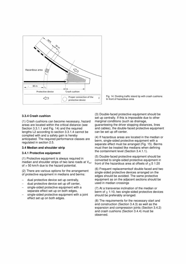
Fig. 14: Dividing traffic island tip with crash cushions In front of hazardous area
3.3.4 Crash cushion
(1) Crash cushions can become necessary, hazard areas are located within the critical distance (see Section 3.3.1.1 and Fig. 14) and the required lengths L2 according to section 3.3.1.4 cannot be complied with and a safety gain is hereby anticipated. The required performance classes are regulated in section 2.5.
3.4 Median and shoulder strip
3.4.1 Protective equipment
(1) Protective equipment is always required in median and shoulder strips of two lane roads at Vzul of > 50 km/h due to the hazard potential.
(2) There are various options for the arrangement of protective equipment in medians and berms:
− dual protective device set up centrally,
− dual protective device set up off center,
− single-sided protective equipment with a separate effect set up on both edges,
− single-sided protective equipment with a joint effect set up on both edges.
(3) Double-faced protective equipment should be set up centrally. If this is impossible due to other marginal conditions (such as drainage, guaranteeing the driver stopping distances, lines and cables), the double-faced protective equipment can be set up off-center.
(4) If hazardous areas are located in the median or berm, single-sided protective equipment with a separate effect must be arranged (Fig. 15). Berms must then be treated like medians when defining the containment level (Section 3.4.1.1).
(5) Double-faced protective equipment should be converted to single-sided protective equipment in front of the hazardous area at offsets of <:5 1:20
(6) Frequent replacementsof double-faced and two single-sided protective devices arranged on the edges should be avoided. The same protective equipment as on the adjacent sections should be used in median crossings
(7) At a transverse inclination of the median or berm of > 1:10, two single-sided protective devices should be preferably arranged.
(8) The requirements for the necessary start and end construction (Section 3.4.3) as well as the expansion and compression joints (Section 3.4.2) and crash cushions (Section 3.4.4) must be observed.
Hazardous area
Protective device Crash cushion
Proper connection of the
protective device

Fig. 15: Protective equipment in front of hazard areas in the median
3.4.1.1 Containment levels
(1) Continuous protective equipment of containment level H2 must be installed in themedian of two lanes roads at Vzul > 50 kmlh. Containment level H4b must be provided in areas with an increased lane departure probability (trucks) and an ADT (SV) of > 3 000 vehicles/24 h.
(2) Continuous protective equipment of containment level H1 must be installed on the bearms of two lane road with Vzul of > 50 km/h. Containment level H2 must be installed in areas with a special risk to third parties (such as gas stations or rest areas at highways or structures at risk of collapse) and an ADT(SV) of > 3 000 vehicles/24h, and if an increased lane departure probability (trucks) exists, containment level H4b must be provided.
(3) Areas with an increased lane departure probability are calculated according to section 3.2.
3.4.1.2 Ranges
(1) The maximum effective range W is determined from the width of the median and the width of the protective device for medians or berms without obstructions. Furthermore, the type of protective device (double-faced or two single-sided protective devices with a separate or joint effect) and their location (centered or off-center) must be observed (Fig. 16 a to 16 d). The effective range for double-faced protective equipment and for single-sided protective equipment with a joint effect may reach up to the inner edge of the marking (mark 295 StVO).
(2) The required effective range for hazard areas in the median and shoulder strip must be calculated according to section 3.3.1.3.
(3) The distance of the front edge of the protective equipment should generally equal 0.5 m from the reference line (Fig. 6). The distance can be reduced in exceptional substantiated cases. Adhering to the required fields of view may require greater distances.
(4) The second protective device in an arrangement of two single-sided protective devices with a separate effect may not be located in the effective range of the first protective device (the greater is decisive in case of variable ranges). This restriction does not apply for single-sided protective equipment, which have proven in a crash test according to DIN EN 1317-2 that they act jointly (meaning combined).
3.4.2 Expansion and compression joints
(1) Expansion and compression joints must be arranged wherever protective devices of various structures and/or functions must be properly connected. The required performance classes are regulated in section 2.3 geregelt.
3.4.3 Start and end construction
(1) Start structures must be provided at the beginning of medians or berms. The required performance classes are regulated in section 2.4. If hazard areas exist, lengts L2 defined in section 3.3.1.4 must be met (Fig. 17).
(2) Start structures must be provided for median crossings, which are temporarily opened, for the duration of the use.
3.4.4 Crash cushion
(1) If lengths L2 defined in section 3.3.1.4 cannot be met at the beginning of medians or berms, crash cushions must be arranged (Fig. 18). The required performance levels are regulated in section 2.5.
(2) If a distance of 50 m to the hazardous area cannot be met in median crossings and if the approved speed cannot be limited to 60 km/h, crash cushions must be provided (Section 2.5).
Offset
Protective device
Offset
Hazardous area

Fig. 16 a: Double-faced protective device set up centered
Fig. 16 b: Double-faced protective device set up off-center
Fig. 16 c: Single-sided protective device with separate effect set up on both edges
Fig. 16 d: Single-sided protective device with a combined effect set up on both edges
Traffic area Traffic area
Re
fere
nce
line
Re
fere
nce
line
Distance of the roadway
a=distance of front of protective device to the roadway W=maximum effective area
B=system width of the protective device
Distance of the roadway
Distance of the roadway
Distance of the roadway
Traffic area Traffic area
Traffic area Traffic area
Traffic area Traffic area
Re
fere
nce
line
Re
fere
nce
line
Re
fere
nce
line
Re
fere
nce
line
Re
fere
nce
line
Re
fere
nce
line
a=distance of front of protective device to the roadway W=maximum effective area
B=system width of the protective device
a=distance of front of protective device to the roadway W=maximum effective area
B=system width of the protective device
a=distance of front of protective device to the roadway W=maximum effective area
B=system width of the protective device

Fig. 17: Single acting protective equipment with start and end construction at the beginning of the median or berm
Fig. 18: Crash cushion at the beginning of the median and shoulder strip
3.5 Edges of bridges and support walls
(1) The following regulations for bridges and support walls apply for crash heights of more than 2 m, otherwise, section 3.3 applies.
3.5.1 Protective equipment
(1) The protective devices must be selected in reference to the hazardous area below the bridge or the support wall on bridges and support walls in valleys within the course of the roads next to the outer edge of the roadway.
(2) The forces that are introduced into the structure by the protective device and the vehicle must be proved in an addition measurement in a crash test for the protective devices on bridges. This verification can be provided by theoretical deliberations for protective devices of containment level HI and N2. Additional regulations for managing the verification may be found in the “Additional Technical Contract Requirements and Guidelines for Engineered Structures" (ZTV-ING).
3.5.1.1 Containment levels
(1) Protective devices of containment levels according to table 5 must be arranged on bridges and support walls in valleys within roads, in addition to roads.
(2) Section 3.3.1.2 applies for bridges with a clear width of less than 10 m and for passages.
3.5.1.2 Effective ranges
(1) The edge of the bridge or the support wall is considered to be the front edge of the hazardous area in the definition of the maximum effective area class, provided no noise barrier or other hazard areas exist. Protective equipment with a greater effective area class can be used, if tests according to DIN EN 1317-2 show that vehicles are still stopped. The desired protection target may thereby not be restricted.
3.5.1.3 Lengths
(1) The definitions of section 3.3.1.4 apply for the lengths of protective devices, especially lengths L2 must be guaranteed. In addition, the location where the protective device has its full effect must be so far from the start of the bridge of support wall that a crash is potentially prevented (Fig. 19, case a).
(2) This means that protective devices with a containment level installed on the bridge must be continued beyond the bridge ends. If this is impossible, the protective device can end at the bridge or support wall, if a protective device of the same containment level is connected (connecting structure; Fig. 19, case b). The definitions of sevtion 3.3.1.4 apply for the lengths of the connecting structure. The definitions in section 2.3 apply for a potentially required transition structure.
Hazardous area
Protective device
or
Protective device or
Hazardous area
Crash cushion
Proper connection of the
protective device

Table 5: Required containment levels on bridges and support walls
Roads with Hazard area below the bridge or support wall
Vzul > 100 km/h and highways
and similar roads with
Vzul: < 100 km/h
Vzul< 100 km/h Und
ADT(SV) > 500 vehicles/24 h
Vzul< 100 km/h and
ADT(SV) < 500 vehicles/24 h
Vzul < 50 km/h
Special risk to third parties (such as explosive chemical plants, intensively used locations, rapid transit lines with approved speeds of
> 160 km/h, two lane roads), compare hazard level 1 in section 3.3
H4b
H2
.
H2
H1
Other cases, comparable hazard levels 2 to 4 in section 3.3
H2 H2 H1 Curbs with a height of 0,15 m to 0,20 m and guard rails with ropes according to RiZ-ING
Fig. 19: Protective device in the area of bridges
3.5.1.4 Areas of flexible expansion joints
(1) Protective devices must be arranged in the area of flexible lane crossings so that their function is not essentially affected by dilatation impacts.
3.5.2 Expansion and compression joints
(1) Expansion and compression joints must be arranged where protective devices of various structures and/or functions must be properly connected. The required performance classes are regulated in section 2.3.
Area with potential
crash risk Bridge
Bridge
Bridge
Area with potential
crash risk
Case a: Protective device on the bridge
Length of the protective device L >L
Case b: Protective device with connecting structure on the bridge
Length of the protective device is limited
on the bridge
Connecting structure Connecting structure

3.5.3 Start and end construction
(1) The required performance classes of start and end structures are regulated in section 204 gerege1t.
3.5.4 Crash cushion
(1) In order to counteract the risk of a crash, crash cushions should be arranged on bridges in the area of dividing traffic island tips (Fig. 20). The required performance levels are regulated in section 2.5, unless additional requirements for special risks to third parties (such as special measures against the crash of trucks) must be fulfilled.
3.6 Medians and berms on bridges
3.6.1 Protective equipment
(1) The selection of the protective devices in medians or berms on bridges is relative whether a height offset of the superstructures is available.
(2) Additional measurements during the crash test must verify which forces are introduced in the bridge structure by the protective device and the vehicle for protective equipment on bridges. This verification can be provided by theoretical deliberations for protective devices of containment level H1 and N2. Additional regulations for managing the verification are located in the “Additional Technical Contract Requirements and Guidelines for Engineered Structures" (ZTV-ING).
3.6.1.1 Containment levels
(1) Section 3.4.1.1 applies for protective devices in medians or berms on bridges with separate superstructures, which do not have a height offset of more than 1.5 m or a clear distance of more than 1.5m (protective equipment with separate effect), as well as on bridges with a joint superstructure.
Fig. 20: Exemplary use of crash cushions on dividing traffic island tips on bridges
(2) The two structures must be observed separately on bridges with separate superstructures, which have a height offset of more than 1.5 m and/or a clear distance of more than 1.5 m. Section 3.5.1.1 will then apply.
3.6.1.2 Ranges
(1) Section 3.4.1.2 applies for bridges with separate superstructures, which do not have a height offset of more than 0.1 m or a clear distance of more than 0.1 m, as well as bridges with a joint superstructure.
(2) The two structures must be observed separately on bridges with separate superstructures, which have a height offset of more than 0.1 m and/or a clear distance of more than 0.1 m aufweisen. Section 3.5.1.2 then applies. Thereby must be noted that a higher bridge superstructure of more than 0.1 m represents a hazardous area. Furthermore must be noted that the higher located superstructure can restrict the effective range.
3.6.1.3 Areas of flexible expansion joints
(1) Protective devices in the area of flexible expansion joints must be designed so that their function is not essentially restricted by dilation impacts.
3.6.2 Structural transition
(1) Expansion and compression joints must be arranged where protective devices of various types and/or function must be properly connected. The required performance classes are regulated in section 2.3.
Possible special measures
against truck crash
Lower lying traffic
area
Protective device Crash cushion
Proper connection of the
protective device

Fig. 21: Exemplary illustration of transitional structures and protective devices in front of a tunnel portal
3.7 Walls and portals
3.7.1 Safety equipment
(1) Continuous solid walls must not be classified as obstructions within the scope of this guideline; if they have no projections or recesses of more than 0.1 m. Niches in tunnels required for safety of less than 4 m in length can be disregarded.
(2) The beginning of continuous walls and portals, projections of more than 0.1 m and the end of niches with a length of more than 4 m must be classified as non-deforming extensive obstacles vertically in the direction of travel (hazard level 3 according to section 3.3 and Fig. 7 in section 3.3.1.2), if they are not constructed so that an impact is harmless to vehicle occupants.
(3) The definition of the areas of the protective device to be installed is defined in section 3.3.1.3.
The required lengths of the protective devices are regulated in section 3.3.1.4.
3.7.2 Structural transitions
(1) The required performance classes of expansion and compression joints are regulated in section 2.3.
3.7.3 Start and end construction
(1) Start and end structures according to section 2.4 must be arranged at the beginning and end of the protective device.
3.7.4 Crash cushion
(1) Crash cushions can also be used before walls, portals and at the end of niches. The required performance classes are regulated in section 2.5.
Tunnel – end formation
Emergency walkway
Transitional structure Protective device
Maximum offset 1:12
Maximum offset 1:12
Ramp
Ramp Berm
Berm
force-closed joint of the protective
device with transitional structure

Appendix 1 Technical regulations DIN1),2) DIN EN 1317-1
DIN EN 1317-2 DIN EN 1317-3 DIN Y ENY 1317-4 DIN EN 1317-5 DIN EN 12767
Restraint systems on roads - Part 1: Terminology and general criteria for test procedures
Restraint systems on roads - Part 2: Performance classes, acceptance criteria for crash tests and test procedures for Protective equipment
Restraint systems on roads - part 3: Performance classes, acceptance criteria for crash tests and test procedures for crash cushions
Restraint systems on roads – part 4: Performance classes, acceptance criteria for crash tests and test procedures for start, end and expansion and compression joints of protective devices
Restraint systems on roads - Part 5: Requirements for the products, conformity procedure and certification for vehicle restraint systems
Passive Sicherheit von support structures fiir die Roadsausstattung – Anforderung en and test procedures
FGSV2)
RAA RAL RASt RAS-L RiStWag TL-BSWF TL-SP TL-SPU ZTY-ING ZTY-PS ZTY-SA
Leaflet for the analysis of traffic accidents, Part 1: Managing and analyzing accident type cards (FGSY 316/1)
Principles for setting up traffic signs on Federal highways - General circular for road construction No. 21/2000 (FGSY 329/3)
Guidelines for installing highways (FGSY 202)
Guidelines for installing rural roads (in preparation)
Guidelines for installing city roads (FGSY 200)
Guidelines for installing roads, part: routing (FGSY 296)
Guidelines for construction measures on roads in water reserves (FGSY 514)
Technical delivery terms for concrete prefabricated safety wall parts (FGSY 362)
Technical delivery terms for steel crash barriers (FGSY 366)
Technical delivery terms for protective crash barrier post covers (FGSY 360)
Additional technical contract provisions and guidelines for engineered structures
Additional technical contract provisions and guidelines for passive protective devices (FGSY 367)
Additional technical contract provisions and guidelines for safety operations at work areas on roadways (FGSY 369)
YkB13),4)
RiZ-ING Diagrams for engineered structures
BMV4)
StYO Road traffic ordinance
Suppliers 1) Beuth Verlag GmbH Address: Burggrafenstrasse 6, 10787 Berlin
Tel.: 0 30/26 01-0, Fax: 030/2601-1260 E-Mail: [email protected], Internet: www.beuth.de
2) FGSV Verlag GmbH Address: Wesselinger Strasse 17,50999 Koeln
Tel.: 0 22 36/38 46 30, Fax: 0 22 36/38 46 40 E-Mail: [email protected], Internet: www.fgsv-verlag.de
All listed FGSV regulations are also contained in the subscription service "FGSV - Technisches Regelwerk - Digital" 3) Verkehrsblatt-Verlag Address: Schleefstrasse 14, 44287 Dortmund Tel.: 0 180/534 01 40, Fax: 0 180/534 01 20
E-Mail: [email protected], Internet: www.verkehrsblatt.de 4) Federal Ministry for Traffic, Construction and Urban Development Internet: www.bmvbs.de

Appendix 2
Terms Crash area Movement area of the vehicle after the impact on a start and end construction during crash tests according to DIN V ENV 1317-4.
Distance, critical Distance, within which must be tested, if a protective device is require, if hazard areas are located within (area requiring protection, obstacle).
Distance, decisive distance between the edge of the roadway and the edge of the hazardous area (obstacle, area requiring protection).
Start and end construction End anchoring / development of a protective device.
Crash cushion Selectively vehicle restraint system installed in front of dangerous obstacles to convert the impact energy into deformation energy.
Impact severity level Theoretical identification for estimating the physical stress, severity of injuries or risk of death for vehicle occupants at a crash on vehicle restraint systems.
Connecting joints Connected expansion and compression joint or protective devices connected without expansion and compression joints of the same cross-section in the area of bridges.
Containment level Identification of the stopping capacity of a vehicle restraint system in reference to the vehicle dimension, crash angle and crash speed during crash tests according to DIN EN 1317.
Permanent lateral offset Permanent lateral deformation of crash cushions as well as the start and end construction in crash tests according to DIN EN 1317-3 and DIN V ENV 1317-4.
Dynamic deflection The dynamic deflection of vehicle restraint systems is determined in the crash test according to DIN EN 1317-2. It corresponds with the maximum lateral dynamic (possibly only brief) offset of the side of the system that is facing the traffic.
Vehicle restraint system Systems constructed on roads that can stop or return or divert a vehicle that departs from the roadway.
Hazardous area An area or a section next to the roadway, in which hazards exist for uninvolved third parties, areas or occupants of vehicles requiring protection, if vehicles depart the roadway.
Guard rails Restraining system constructed for pedestrians or other road users serving as vehicle restraint system, such as on bridges, support walls or similar engineered structures.
Performance class of DIN EN 1317-2 The performance class of a protective device and expansion and compression joint is defined by the containment level, the effective range and the impact severity level.
Performance class of DIN V ENV 1317-4 The performance class of a start and end construction is determined by the performance class (verified by crash tests), the lateral deflection, the crash area and the impact severity level.
Performance level of DIN EN 1317-3 The performance level of a crash cushion is determine by the speed index, the lateral offset, the return area and the impact severity level.
Protective device Vehicle restraint system, which is constructed along the outer edge of the roadway or in medians and berms.
Structural transition Vehicle restraint system for the mechanical connection between restraint systems and protective devices of various structural types and/or various functions during vehicle crashes.
Deformation class The deformation class identifies various deformations and offsets of crash cushions during crash tests according to DIN EN 1317-3.
Effective range Distance between the side of a protective device facing traffic and the maximum dynamic lateral position of each essential part of the system during crash tests according to DIN EN 1317-2.
Return area The return area is determined during crash tests according to DIN EN 1317-3. It describes the area, which the test vehicle may not leave after the crash.

Appendix 3 Excerpts from DIN EN 1317 Table A 1: Protective devices - criteria for crash tests (from DIN EN 1317-2)
Test Impact speed
Impact angle Total mass of the vehicle
Vehicle type
TB 11 100 km/h 20° 900 kg Passenger vehicle TB 21 80 km/h 8° 1300 kg Passenger vehicle TB 22 80 km/h 15° 1300 kg Passenger vehicle TB 31 80 km/h 20° 1500 kg Passenger vehicle TB 32 110 km/h 20° 1500 kg Passenger vehicle TB 41 70 km/h 8° 10000 kg Truck TB 42 70 km/h 15° 10000 kg Truck TB 51 70 km/h 20° 13000 kg Bus TB 61 80 km/h 20° 16000 kg Truck TB 71 65 km/h 20° 30000 kg Truck TB 81 65 km/h 20° 38000 kg Tractor trailer
Table A 2: Protective devices - Containment levels (from DIN EN1317-2)
Containment levels Acceptance test
Normal restraining capacity N1 N2
TB 31 TB 32 and TB 11
Greater restraining capacity H1 H2 H3
TB 42 and TB 11 TB 51 and TB 11 TB 61 and TB 11
Very high restraining capacity H4a H4b
TB 71 and TB 11 TB 81 and TB 11
Table A 3: Protective devices - Impact severity levels (from DIN EN1317-2)
Impact severity level Characteristic values
A ASI " 1,0
B 1,0 < ASI " 1,4
C 1,4 < ASI " 1,9
and
THIV " 33 km/h PHD" 20 9
Table A 4: Protective devices – levels of the effective range (from DIN EN 1317-2)
Effective range classes Levels of the effective range
W1 W" 0,6 m W2 W" 0,8 m W3 W" 1,0 m W4 W" 1,3 m W5 W,,1,7m W6 W" 2,1 m W7 W" 2,5 m W8 W" 3,5 m

Table A 5: Start and end construction - criteria for crash tests and performance classes (from DINV ENV1317-4)
Prufunqen Performance classes
Location
Approach Vehicle mass Speed Test description
frontal, 1/4 offset toward the roadway
900 kg 80 km/h TI 2.1.80 U
Lateral impact, 15°,2/3 L
1300 kg 80 km/h TT 4.2.80
P2
A
D
Lateral impact, 165°,1/2 L
900 kg 80 km/h TT 5.1.80
Table A 6: Start and end construction – threshold values for the permanent lateral deflection (from DIN V ENV1317-4)
Name of the class Lateral deflection
1 0.5 m
2 1.5 m
x
3
Da
3.0 m
1 1.0 m
2 2.0 m
3 3.5 m
y
4
Dct
>3.5 m
Table A 7: Start and end construction – Dimensions Za and Zd of the impact area (from DIN V ENV1317-4)
Classes of Z Approach side Za Impact side z, Z1 4m 4m Z2 6m 6m Z3 4m No limit Z4 6m No limit
Table A 8: Crash cushion - criteria for crash tests (from DIN EN 1317-3)
Test Impact Total mass of the vehicle
Speed
TC 1.1.50 50 km/h TC 1.1.80 80 km/h TC1.1.100
900 kg
100 km/h TC 1.2.80 80 km/h TC 1.2.100
1300 kg 100 km/h
TC 1.3.110
frontal, center
1500 kg 110 km/h TC 2.1.80 80 km/h TC 2.1.100
frontal, 1/4 vehicle offset
900 kg 100 km/h
TC 3.2.80 80 km/h
TC 3.2.100
1300 kg
100 km/h
TC3.3.110
Front (center) at 15°
1500 kg 110km/h
TC 4.2.50 50 km/h
TC 4.2.80 80 km/h TC 4.2.100
1300 kg
100 km/h TC 4.3.110
Side impact at 15°
1500 kg 110 km/h TC 5.2.80 80 km/h
TC 5.2.100 1300 kg
100 km/h
TC 5.3.110
Side impact at 165°
1500 kg 110 km/h

Table A 9: Crash cushions – measurements for the return area (Za and Zd) (from DIN EN 1317-3)
Approach side Impact side Classes for Z
Za Zd Z1 4m 4m Z2 6m 6m Z3 4m ;" 4 m (Test 3, Fig. 1) Z4 6m ;" 6 m (Test 3, Fig. 1)
Table A 10: Crash cushions – areas for the permanent lateral offset (Da and Dd) of crash cushions (aus DIN EN 1317-3)
Offset Classes Da Dd
01 0,5 m 0,5 m 02 1,0 m 1,0 m 03 2,0 m 2,0 m 04 3,0 m 3,0 m 05 0,5 m ;" 0,5 m (Test 3, BUd 1) 06 1,0 m ;" 1,0 m (Test 3, Fig. 1) 07 2,0 m ;" 2,0 m (Test 3, Fig. 1) 08 3,0 m ;" 3,0 m (Test 3, Fig. 1)

Explanation of the System of Technical Publications of FGSV
R stands for regulations:
Such publications either regulate how technical facts must be or should be planned or implemented (R 1), or recommend how these are planned or implemented (R 2).
W stands for knowledge documents:
Such publications show the current state of knowledge and explain how technical facts can be treated or has already been successfully treated.
The category R 1 describes the regulations of the 1st category: R 1 publications include the contract principles (ZTV – additional technical contract provisions and guidelines, TL – Technical delivery terms and TP - Technical test regulations) as well as guidelines. They are always coordinated within FGSV. They have a high binding force, especially if they should be agreed on as a contract component.
The category R 2 describes the regulations of the 2nd category: R 2 publications include leaflets and recommendations. They are coordinated within FGSV. FGSV recommends their application as state of the art.
The category W 1 describes knowledge documents of the 1st category: W 1 publications include references. They are always coordinated within FGSV, however, not with external parties. They reflect the current state of knowledge within the responsible FGSV committees.
The category W 2 describes knowledge documents of the 2nd category: W 2 publications include working papers. These can be current standings when establishing developing activities or information and working aids. They are not coordinated within FGSV; they reflect the perception of a single FGSV committee.