guidelines for the development of process specifications ... processing... · guidelines for the...
TRANSCRIPT

Guidelines for the Development of Guidelines for the Development of Process Specifications, Instructions, Process Specifications, Instructions, and Controls for the Fabrication of and Controls for the Fabrication of
FiberFiber--Reinforced Polymer Reinforced Polymer Composites by Liquid MoldingComposites by Liquid Molding
Larry Gintert & John Bayldon

17th Sept 2003 Larry Gintert John Bayldon
Liquid Resin MoldingLiquid Resin Molding
Liquid Resin Molding (LRM) processes are classified as any processes where liquid resin is infused into a dry fiber perform.
Closed-Cavity Mold- Open Cavity Mold-
All surfaces controlled by rigid tooling
Only a portion of the part controlled by rigid tooling
17th Sept 2003 Larry Gintert John Bayldon
ObjectiveObjective
Guidelines for the development of liquid resin molding (LRM) process specifications for the fabrication of continuous fiber-reinforced polymer composite test panels used in the generation of mechanical propertiesAn approach for the validation of composite LRM fabrication processes used during the certification of composite aircraft structure

17th Sept 2003 Larry Gintert John Bayldon
LRM Process FlowLRM Process Flow
Resin Mixing
Mold Assembly/Closure
Infusion
Cure
Demolding
Resin Reception/Storage
Fiber Reception/Storage
Other Included Items Reception/Storage
Preform Assembly
Mold Preparation
17th Sept 2003 Larry Gintert John Bayldon
Certification ProcessCertification Process
Design validation process: to establish by proof, is accomplished through – Verification (to prove by evidence) and – Qualification (to define attributes or
characteristics) of the materials, processes, and analysis tools.

17th Sept 2003 Larry Gintert John Bayldon
Material Qualification Material Qualification
Qualification tests are planned and conducted to– Establish key material attributes– Establish material performance properties– Verify material characteristics will work in the intended
application.
The objective in defining material attributes is to establish the constituent material property limits.

17th Sept 2003 Larry Gintert John Bayldon
Preform Attributes:Preform Attributes:
Fiber pedigreePly dimensions, alignment and stacking sequenceShaped preform contoursDe-bulked preform fiber volumeFiber sizing level and type,Quantity of tackifiers and/or binders used, andCompatibility of constituent materials with each other

17th Sept 2003 Larry Gintert John Bayldon
Liquid Resin AttributesLiquid Resin Attributes
Initial mix viscosity (at a defined temperature)Initial mix heat of reaction (ΔHult)Mix chemistry (e.g. ratio of epoxide:amine groups in some epoxy chemistries)Amount of entrained air or solventThermal conductivity

17th Sept 2003 Larry Gintert John Bayldon
Process Specification Process Specification GuidelinesGuidelines
Process specifications Material specificationsPlanningWork instructionsTest plans

17th Sept 2003 Larry Gintert John Bayldon
Fabrication Specification Fabrication Specification SectionsSections
Work InstructionsPersonnelMaterialsEquipment DescriptionFacility DescriptionToolingPanel LaminationPanel AcceptanceProcess Monitoring

17th Sept 2003 Larry Gintert John Bayldon
2.1 Work Instructions2.1 Work InstructionsRequirements and procedures to be used in the fabrication process. Detailed step-by-step work instructions in conjunction with process specifications
17th Sept 2003 Larry Gintert John Bayldon
2.2 Personnel2.2 Personnel
Recommended Personnel Selection Factors– Experience– Inspection personnel, ratio to manufacturing
personnel– Level of training– Personnel status identified (qualified or
unqualified)

17th Sept 2003 Larry Gintert John Bayldon
Materials ControlsMaterials Controls
Traceability – From raw fiber, or basic raw materials
Storage Requirements– Humidity– Temperature
Records

17th Sept 2003 Larry Gintert John Bayldon
2.4 Equipment Description2.4 Equipment Description
Equipment Calibration– Ovens – Liquid resin delivery devices (such as pumps) – Thermocouples – Vacuum gages, and ply-warming devices (e.g.,
hot-air guns)
17th Sept 2003 Larry Gintert John Bayldon
2.6 Tooling2.6 Tooling
Flat, closed-cavity mold with a uniform thickness cavity, for closed-cavity LRM Flat base plate and perhaps a reusable bladder for open-cavity LRM processing Engineering Performance:– Assembly procedure, infusion parameters/pressures,
cure temperature and packing pressure, surface finish and flatness requirements should be defined
– Thermocouples should be placed at the coldest and hottest locations

17th Sept 2003 Larry Gintert John Bayldon
2.6 Tooling Cont.2.6 Tooling Cont.
A method for accurately positioning the plies is required– Control of ply orientation– Transfer of the tool zero direction to the panel and then
to the machining equipment e.g. Scribe lines on the tool Thin metal strips embedded along one edge of the panel
Tool preparation procedures– Tool inspection – Verification that all tooling details are available and in
good working condition

17th Sept 2003 Larry Gintert John Bayldon
2.6 Tooling Cont.2.6 Tooling Cont.
– Method of cleaning, solvents, cleaning cloths– Mold release agents– Tool heat survey results (location of coldest and hottest
thermocouples)– Scribe marking– Templates
Inspection intervalsSurface conditionsMaterialQuantities

17th Sept 2003 Larry Gintert John Bayldon
2.6 Tooling Cont.2.6 Tooling Cont.– Heat-up rate– Surface conditions– Method of moving, transportation– Condition (mold release applied, and no mold release)– Configuration (flat, vertical)– Status identified (approved, unapproved)– Storage conditions and locations– Expansion and contraction rate– Material– Repair procedures– Inspection intervals– Location and number of vacuum ports– Orientation rosette
17th Sept 2003 Larry Gintert John Bayldon
2.7.1 Preform Fabrication2.7.1 Preform FabricationFrozen reactive materials warmed to room temperature prior to opening Materials should be cut on surfaces specifically dedicated to cutting Individual materials should be identified and marked at the time of cutting Preform tooling – Inspection step with a translucent shaped caul
Accurately align the materials with respect to the tool zero-degree reference direction

17th Sept 2003 Larry Gintert John Bayldon
2.7.1 Preform Fabrication Cont.2.7.1 Preform Fabrication Cont.Mold assembly repeatability– Positive location features and methods that ensure that
the preform is not distorted or damaged – Inspection features with acceptable limits for measured
gaps in the case of closed-cavity molds – Thickness gages and templates in the case of open-
cavity moldsThermocouples – Direct measurement of the panel temperature– Thermocouples placed against the preform to ensure the
material is heated to the specified temperatures– At least two thermocouples should be used for each
panel

17th Sept 2003 Larry Gintert John Bayldon

17th Sept 2003 Larry Gintert John Bayldon

17th Sept 2003 Larry Gintert John Bayldon
2.7.2 Resin Mixing2.7.2 Resin MixingOne Part Systems– Controlled by supplier, and verified by fabricator, large
batches allow for comprehensive testing of final resinFormulated System– Supplier can verify chemistry of components, and
mixing quality of separate parts, but fabricator has to carry out final mixing. Verification of mix ratio and mix quality required
Other– Fabricator must verify chemistry of components,
(before or after mixing,) and then verify mix ratios, and mix quality

17th Sept 2003 Larry Gintert John Bayldon
2.7.2 Resin Options2.7.2 Resin Options
TestTestTestCompatibility
Contamination
Cure State
Mix Ratios
Well Mixed
OtherFormulatedOne part
Indicates Fabricator Controls Required. Indicates generally go

17th Sept 2003 Larry Gintert John Bayldon
2.7.3 Resin Infusion Control2.7.3 Resin Infusion Control
TTool
TInjection
Vacuum
TReservoir
Flow Rate
PInjection

17th Sept 2003 Larry Gintert John Bayldon
2.7.4 Resin Cure2.7.4 Resin Cure
TTool
PPacking
Vent Condition (Open, Closed, Vacuum, Pressurized)
TPart
020406080
100120140160180200
0 100 200 300

17th Sept 2003 Larry Gintert John Bayldon
2.7.5 Panel Identification2.7.5 Panel Identification
The identification number will provide traceability to:– The requesting document – Resin batch number – Preform identification number– Cure cycle– Test type
Lines can also be drawn at an angle across the panel surface to aid in identifying specimen location within the panel.

17th Sept 2003 Larry Gintert John Bayldon
2.8 Inspection and Process 2.8 Inspection and Process Monitoring.Monitoring.
2.8.1 Responsibility for Inspection2.8.2 Process Monitoring and Control2.8.3 Panel Inspection2.8.4 Use of Prolongs/Cut outs

17th Sept 2003 Larry Gintert John Bayldon
2.8.2 Process Monitoring and 2.8.2 Process Monitoring and ControlControl
Data Collection for Quality AssuranceData Collection for SPC
30
35
40
45
50
55
60
65
0 2 4 6 8 10
Control LimitsAction Limits
17th Sept 2003 Larry Gintert John Bayldon
2.8.3 Panel Inspection2.8.3 Panel Inspection
Panel thickness Surface flatnessResin content/reinforcement weight fractionVoid content Composition variations (e.g due to binder migration or resin filtration,)Completeness of cureEmbedded materials
17th Sept 2003 Larry Gintert John Bayldon
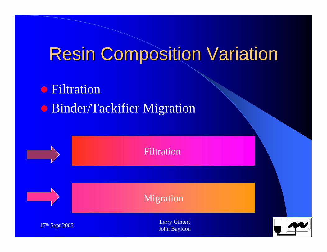
Resin Composition VariationResin Composition Variation
FiltrationBinder/Tackifier Migration
Migration
Filtration
17th Sept 2003 Larry Gintert John Bayldon
2.8.4 Use of Prolongs/Cut2.8.4 Use of Prolongs/Cut--outsoutsTraveler Pieces– Quality control– Statistical process control
Must be included at the earliest stage of the process design Tests– Degree of cure – Final Tg – Flexural strength.
Vent/Gate plugs
17th Sept 2003 Larry Gintert John Bayldon
3 Producibility Validation 3 Producibility Validation GuidelinesGuidelines
3.1 Producibility Qualification Tests– Verification of material behavior for complex shapes
and full scale parts 3.2 Fabricator Qualification– Verification of production parts compared to
development 3.3 Performance Property Equivalency– Verification of materials properties for full scale parts
3.4 Component Structural Equivalency– Verification of structural behavior