gujarat energy transmission corporation … office/021110/03092011... · 2.23 field demonstration...
TRANSCRIPT

TECHNICAL SPECIFICATION FOR SDH/PDH Equipment with integrated Access Multiplexer
Sign & Seal of Bidder
GETCO/E/TS-SDH/PDH FOTE/R1, Dt:16.04.2011
Page 1 of 60
Technical Specification for
PDH / SDH COMMUNICATION EQUIPMENT
STM-1 Equipment with integrated Access Multiplexer
GUJARAT ENERGY TRANSMISSION CORPORATION LIMITED
Sardar Patel Vidyut Bhavan, Race Course,Vadodara – 390 007.

TECHNICAL SPECIFICATION FOR SDH/PDH Equipment with integrated Access Multiplexer
Sign & Seal of Bidder
GETCO/E/TS-SDH/PDH FOTE/R1, Dt:16.04.2011
Page 2 of 60
CONTENT
PDH / SDH COMMUNICATION EQUIPMENT 1
STM-1 / STM-4 EQUIPMENT WITH INTEGRATED ACCESS MULTIPLEXER 1
CONTENT 1,3&4
Special Instruction to Bidder 5
1 Scope of Specification and of works 6
2 Network configuration & equipment characteristics 6 2.1 Introduction 6 2.2 General network characteristics 6 2.2.1 Description 6&7 2.2.2 Functional requirement 7 2.2.3 General System Requirement 7 2.2.3.1 System sysnchronization 7 2.2.3.2 System Maintainability 7&8 2.2.3.3 System Upgradability & Expandability 8 2.2.3.4 Equipment availability 8 2.2.4 Fibre Optics Terminal Equipment 9 2.2.4.1 General Requirement 9&10 2.2.4.2 Teleprotection requirements 10&11 2.2.5 General Equipment Characteristics 11 2.2.5.1 Important Features 11&12 2.2.5.2 General Condition 12,13&14 2.2.5.3 Requirement of transport leve 14&15 2.2.5.4 User signal interface 16 to 18 2.2.5.5 System capacity (To be supported) 19 to 22 2.2.5.6 SCHEDULE -A1 : Table of compliance and Configuration of Modules 22 to 28 2.2.5.7 SCHEDULE -B1 : List of type test reports for SDH equipments 29 to 31 2.2.5.8 Redundancy requirement and Protetion Scheme 31 2.2.5.9 Lost signal recovery 32 2.2.5.10 Equipment life span 32 2.2.5.11 Revision Level & Modifications 32 2.3 Fiber Optics (OPGW) Network System 32 2.3.1 General Site consideration 32 2.3.2 Proposed Optical Fibre Characteristics 32 2.3.3 Fibre Optic Link Length 32&33 2.3.4 Redundancy & Protection 33 2.3.5 Supervision & Alarm 34 2.3.6 Synchronization 34

TECHNICAL SPECIFICATION FOR SDH/PDH Equipment with integrated Access Multiplexer
Sign & Seal of Bidder
GETCO/E/TS-SDH/PDH FOTE/R1, Dt:16.04.2011
Page 3 of 60
2.3.7 Electrical & Optical Characteristics and General Parameters 34&35 2.3.8 Optical link performance requirements 35 2.3.8.1 Link Budget Calculations 35 & 36 2.3.8.2 Link Performance 36 2.3.8.3 FODP to SDH equipment/Optical Amplifier Connectivity 36 2.4 MDF,DDF & Cabling 36 2.4.1 MDF and DDF Patching facilitities 36&37 2.5 Patch Cords 37 2.6 Network Management System 37 2.6.1 Applicable Standard 37 2.6.2 NMS Architecture 37&38 2.6.3 Management function 38 2.6.3.1 Configuration Management 38&39 2.6.3.2 Fault Management 39 to 41 2.6.3.3 Security Management 41 2.6.3.4 Performance Management 41&42 2.6.3.5 Interface to external system 42 2.7 Communication Channel Requirement & integration 42&43 2.8 Craft terminal 43 2.9 Hardware requirement 43 2.9.1 Master processor, Server/Workstation and Craft terminal 43&44 2.9.2 Peripherals and Hardware 44 2.9.3 Local/remote operator consoles 44 2.9.4 Power supplies 44 2.10 General software/Firmware requirements 44 2.10.1 Operating System Software 44 2.10.2 Application Software 44
2.10.3 Software abilities 44&45
2.10.4 Revision, Upgrades, Maintainability 45
2.10.5 Database (S) 45
2.10.6 Help 45
2.11 Summary of standards 46 to 48
2.12 Prequalification Requirements 49&52
2.13 Special Condition to bidder 52
2.14 Schedule of requirements 53

TECHNICAL SPECIFICATION FOR SDH/PDH Equipment with integrated Access Multiplexer
Sign & Seal of Bidder
GETCO/E/TS-SDH/PDH FOTE/R1, Dt:16.04.2011
Page 4 of 60
2.15 Spares 53
2.16 Tests 53
2.16.1 Type tests 53
2.16.2 Acceptance & Routine tests 54
2.17 Inspection during manufacturing 54
2.18 Quality Assurance plan 54
2.19 Performance Guarantee 54&55
2.20 Demonstration 55
2.21 Documentation 55
2.22 Packing & Transport 56
2.23 Field demonstration & training 56&57
2.24 Supervisory erection & commissioning 57
2.25 Schedules 57
2.26 Information to be filled in invariably by the bidder 58
2.27 Unit rate for each item of BOQ 58
2.28 Requirement for first testing and commissioning 58
2.29 BOQ 59
2.30 Abbreviations 59&60
SCHEDULE - C1 Deviation from Specification 60
SCHEDULE - D1 Schedule of Bidder's Experience 60
SCHEDULE - E1 Schedule to indicate Bidder's Capability 60

TECHNICAL SPECIFICATION FOR SDH/PDH Equipment with integrated Access Multiplexer
Sign & Seal of Bidder
GETCO/E/TS-SDH/PDH FOTE/R1, Dt:16.04.2011
Page 5 of 60
SPECIAL INSTRUCTIONS TO BIDDER
Please read following instructions carefully before submitting your bid.
1. All the drawings, i.e. elevation, side view, plan, cross sectional view etc., in AutoCAD format and manuals in PDF format, for offered item shall be submitted. Also the hard copies as per specification shall be submitted.
2. The bidder shall submit Quality Assurance Plan for manufacturing process and
Field Quality Plan with the technical bid. 3. The bidder shall have to submit all the required type test reports for the offered
item. In case of non-submission of the type test reports with the offer, the bid shall be liable to be rejected.
4. The bidder must fill up all the point of GTP for offered item/s. Instead of
indicating “refer drawing, or as per IS/IEC”, the exact value/s must be filled in. 5. All the points other than GTP, which are asked to confirm in technical
specifications must be submitted separately with the bid. 6. The bidder is required to impart training in view of manufacture, assembly,
erection, operation and maintenance for offered item, at his works, to the person/s identified by GETCO, in the event of an order, free of cost.
7. Please note that the evaluation will be carried out on the strength of content of
bid only. No further correspondence will be made. 8. The bidder shall bring out all the technical deviation/s only at the specified
annexure.
9. The bidder should indicate manufacturing capacity by submitting latest updated certificate of a Chartered Engineer (CE).

TECHNICAL SPECIFICATION FOR SDH/PDH Equipment with integrated Access Multiplexer
Sign & Seal of Bidder
GETCO/E/TS-SDH/PDH FOTE/R1, Dt:16.04.2011
Page 6 of 60
1. SCOPE OF SPECIFICATION AND WORKS GETCO having total 39518.73 Circuit KM Transmission Line network comprises 400KV, 220KV, 132KV, 66KV & 33KV System. Intent of this specification is to cover engineering, design, manufacturing, testing, supply, storage, erection, installation, Commissioning & maintenance of 155 Mbps Optical Fiber system. The system shall provide one single platform for whole range of application from 64kbits/sec to STM-4. It also supports Expansion / Up gradation in future possible up to STM-16 or STM-64 depending on the needs of time. The system shall be up-gradable to STM 4 level by simple interchange of OLTE SFP module. The system shall offer complete solution for Scada, speech, Teleprotection & Data communication. The offered system shall have integrated Teleportection capability, associated power and signal cabling. The bidder shall have to ensure & co-ordinate with the SCADA Package supplier of the sub-station where FOTE will have to be installed for jointly execution of work of providing connectivity between FOTE & sub-station SCADA system to extend control at remote end for remote control operation. The bidder shall have to provide documentation for each activity related to testing, erection, installation and commissioning and training to ten GETCO personnel.
2. NETWORK CONFIGURATION AND EQUIPMENT CHARACTERISTICS 2.1 Introduction This section describes the Fibre Optic Communication network configuration and the equipment characteristics for communication system to be installed under the project. The systems addressed within this section are:
(1) Fibre Optic Terminal equipment (FOTE) (2) Network Management System (NMS) (4) MDF, DDF and Cabling
The requirements described herein are applicable to and in support of network configurations (as per network group diagram enclosed: Network Layout) and Network Management System (NMS) for monitoring and control of this communication network. 2.2 GENERAL NETWORK CHARACTERISTICS
2.2.1 Description The proposed fibre optic communication network consists shall support the voice, Teleprotection (both distance protection commands operation & line differential protection) & data communication requirements of RTUs and the SCADA/EMS system. The communication system shall provide data & voice connectivity across the various locations or connectivity of RTUs with Sub-LDCs and Sub-LDCs with SLDC. The RTUs located at various locations will report to Control Center using IEC 870-5-101 or IEC 870-5-104 Protocol. The proposed communication system shall also support Ethernet interface for RTUs over TCP/IP protocol and serial interface. The fibre optic network shall be based on the lowest bit rate of the Synchronous Digital Hierarchy (SDH) i.e. STM-1. However, the offered equipment can be upgraded to STM-4 by changing the optical SFP only. The Contractor can propose a system based on higher bit rate systems, if required, so as to meet the link budget requirements or

TECHNICAL SPECIFICATION FOR SDH/PDH Equipment with integrated Access Multiplexer
Sign & Seal of Bidder
GETCO/E/TS-SDH/PDH FOTE/R1, Dt:16.04.2011
Page 7 of 60
any other specification requirement. The detailed BOQ is described in ‘Schedule of BOQ’ enclosed.
2.2.2 Functional Requirement
The primary function of the communication network is to provide a highly reliable voice, teleprotection and data communication system in support of the SCADA/EMS. The communications support requirement for SCADA/EMS system is for low & high speed data, express voice circuits and administrative voice circuits. A brief summary of the communication system requirements is as follows: (a) integrated distance teleprotection commands interface as well as line differential
protection interface (Optical Protection relay interface C37.94) fully manageable under the same NMS
(b) 64kbps & nx64kbps data channel support (c) Low speed (300 -1200 bps) data channel support (d) 6 wires E & M channel support. (e) Data transport supporting Network Management channels (f) The connectivity envisaged between RTUs and Control Centre is Wide Area Network (WAN) on TCP-IP using IEC 610870-5-104 protocol and serial using IEC 610870-5-101 protocol. 2.2.3 General Systems Requirements Required characteristics are defined and specified herein at system level. 2.2.3.1 System Synchronization The Bidder shall synchronize the equipments under the contract by providing Master clock and slave clocks, as required. Contractor shall provide the slave clocks as required under the set of clock indicated in BOQ. The contractor shall submit the synchronisation plan as per standard ITU-TG.811. All sync equipments proposed under this contract should meet ITU-T G.811 criterion. The holdover quality of slave clock shall meet ITU-T G.812 standard requirements. The Contractor shall provide system wide synchronization fully distributed throughout the telecom network and connected to all equipments. The Contractor shall submit the synchronization plan for the entire network meeting the requirement of ITU-T G.803. The system equipment requiring “clock” shall be connected to the master clock using external clocking. For this purpose, appropriate interfaces(s) in the transmission & termination equipment being supplied and all other associated hardware shall be provided by the Bidder. 2.2.3.2 System Maintainability To facilitate performance trending, efficient diagnosis and corrective resolution, the system shall permit in-service diagnostic testing to be executed both locally and from remote locations, manually and/or initiated under NMS control. Such testing shall not affect the functional operation of the system.

TECHNICAL SPECIFICATION FOR SDH/PDH Equipment with integrated Access Multiplexer
Sign & Seal of Bidder
GETCO/E/TS-SDH/PDH FOTE/R1, Dt:16.04.2011
Page 8 of 60
Preventive and problem oriented maintenance of the communications system shall be performed using diagnostics tools such as NMS and test equipments (Optical power meter, communication analyser etc.). They shall support complete maintenance of all system elements and shall permit the diagnosis of any without requiring additional test equipment. The Contractor shall provide specialized training required to operate above mentioned diagnostic tools. For all redundant systems, disconnection and repair of any failed device shall not interrupt the operation of the system. 2.2.3.3 System Upgradability and Expandability Equipment supplied shall be sized (though not necessarily equipped) to support system expansion to full capacity specified at clause No. 2.2.5.5 of TS. Power supplies and NMS shall be sized for maximum equipped system capacity.
2.2.3.4 Equipment Availability The availability requirements is categorised in two parts. The Contractor shall ensure the availability for subscriber to subscriber where they will have to provide the new equipments (MUX/Drop-Insert) under this contract. The availability requirements are as follows, which shall be demonstrated at site for the equipments being provided under this contract: A. New nodes with requirement of both SDH STM-1 ADM equipment (1) The average per link subscriber to subscriber availability shall be at least 99.97%.
The average per link subscriber to subscriber availability is defined as the availability between any two data or voice subscribers/Teleprotection channel.
(2) The network-wide subscriber to subscriber availability shall be at least 99.8% .The network-wide subscriber to subscriber availability is defined as the availability between any two data or voice subscribers/Teleprotection channel on the wideband network.
The calculated availability is defined as the theoretical availability determined by a statistical calculation based on the mean-time-between-failure (MTBF) and the mean-time-to-repair (MTTR) of the components and modules comprising the FOTE. The down time of the fibre optic cable shall not be considered in the aforesaid availability calculations. In order to ensure that the equipment & configuration proposed by the bidders shall be capable of demonstrating the specified availability figures, it is required that the Bidders shall include in their proposal a calculated availability analysis for the proposed equipment. The calculated failure rates of the units and the calculated availabilities of the equipment being offered shall be provided in the proposal. The analysis shall be based on an availability block diagram and shall include the mean-time-between failure (MTBF) and mean-time-to-repair (MTTR) of all of the components on the link. The Contractor shall indicate in the analysis the MTBF and MTTR and the resulting availability of each point-to-point link. For this analysis, an MTTR of at least 4 hours shall be assumed.

TECHNICAL SPECIFICATION FOR SDH/PDH Equipment with integrated Access Multiplexer
Sign & Seal of Bidder
GETCO/E/TS-SDH/PDH FOTE/R1, Dt:16.04.2011
Page 9 of 60
2.2.4 Fibre Optics terminal Equipment The Fibre Optic Terminal Equipment (FOTE) for communication System is defined herein to include ETSI digital optical line termination equipment. The FOTE shall be based on SDH technology. Minimum aggregate bit rate shall be STM-1. The Contractor shall provide (supply and install) connectorised jumpers (patch cords) for FODP-to-equipment connection. Two number spare jumpers shall be provided for each equipment connection. Fibre jumpers shall be of sufficient lengths as to provide at least 0.5m of service loop when connected for their intended purpose.
2.2.4.1 General requirements The digital multiplex equipment shall be designed to operate in electrical high-voltage networks and shall be suitable for installations in substations with harsh environment and high electromagnetic interference. It shall be highly reliable and provide secure communications for real time signals such as voice, SCADA, teleprotection, data including IP/Ethernet and status/control signals. The equipment offered shall already be working successfully in telecommunication networks operated by power utilities. It shall comply with the latest ITU-T recommendations and ETSI standards and be able to be interconnected with legacy multiplex and other telecommunication equipment. On TRANSPORT LEVEL interfaces for optical transmission on PDH 8Mbit/s, STM-1 155Mbit/s and STM-4 622Mbit/s shall be available. Additionally 2Mbit/s x DSL (HDSL or SDHSL) interfaces shall be available for connection to copper cables. For connection to higher order transport equipment also N x 2Mbit/s and STM-1 electrical interfaces shall be available. The equipment shall be software controlled, of modular design and all modules shall form an integrated part of a 19” shelf. The expandability for requirement to be supported by offered equipment shall be obtained by just inserting the cards in access multiplexer. The platform shall have means to cross-connect, drop and insert individual channels (64kbit/s time slots), 2Mbit/s framed (G.704) and unframed (G.703) signals. It shall also support termination and cross connection of VC 12, VC-3 and VC-4. Equipment protection and various protection schemes shall be supported.
For stations with teleprotection and telecommunication requirements an integrated teleprotection function (distance and differential protection) has to be provided. The interface for command (4 independent commands per interface for sending/receiving signals with operation of distance protection scheme of transmission line) transmission & reception shall be supported by offered system and same shall be obtained by just inserting modular interface card in the slots available in 19” rack arrangement of the main SDH (STM-1 ADM) system. The protection signal interconnectivity for transit operations of command transmit/receive from different direction shall also be supported in stations, where existing equipments have to be extended. Each network element shall be manageable locally and also from an operation centre. There shall be the means available to supervise external/existing equipment via binary

TECHNICAL SPECIFICATION FOR SDH/PDH Equipment with integrated Access Multiplexer
Sign & Seal of Bidder
GETCO/E/TS-SDH/PDH FOTE/R1, Dt:16.04.2011
Page 10 of 60
signals. - It must be possible to access the platform over a TCP-IP network. Access over SDH OHC channel using the OSI protocol shall be possible.
Modules for direct connection to following USER SIGNALS shall be available as plug-in modules for the equipment:
• Analogue subscriber interface: subscriber and exchange side • 4-wire E&M voice interface • G.703, 64kbit/s data Interface • X.24/V.11 (RS-422), N x 64kbit/s data interface • V.24/V.28 (RS-232), data interface • V.35, N x 64kbit/s data interface • RS485 data interface • Programmable data interface V.24,/V.28, V.35, X.24/V.11 • Alarm collection interface • Teleprotection command interface • Optical protection relay interface C37.94 • Binary signal (status and control) interface • 2Mbit/s electrical interface for unframed signals acc. to ITU-T G.703
and framed signals acc. to G.703 and G.704. • LAN interface 10/100BaseT electrical interface RJ45, IP/Ethernet • LAN Interface for 100BaseFX and 1000BaseLX/SX, IP/Ethernet
On TRANSPORT LEVEL the equipment shall support the following connection ports:
• Up to 8 STM-4 SDH optical ports • Up to 16 STM-1 SDH optical ports for medium and long distances, with
automatic laser shut down programmable on each interface. • Up to 4 STM-1 SDH electrical ports • Up to 8 8Mbit/s optical ports • Up to 16 2Mbit/s HDSL ports
All optical ports shall support SFPs (small-factor pluggable unit) for short, medium, long and extra-long optical communication. ALS (Automatic Laser Shut-down) shall be fully supported. 2.2.4.2 Teleprotection Requirements (To transmit/receive command on operation of distance protection Scheme of transmission line) The Teleprotection and communication system has to ensure the easy and secure function of the teleprotection. Therefore following features have to be provided:
• At least an 8 bit command addressing for teleprotection signal shall be provided to prevent tripping if the signal is inadvertently re-routed through the telecommunication network.
• An automatic and periodic loop test (<100s) has to be provided for a signal delay measurement.

TECHNICAL SPECIFICATION FOR SDH/PDH Equipment with integrated Access Multiplexer
Sign & Seal of Bidder
GETCO/E/TS-SDH/PDH FOTE/R1, Dt:16.04.2011
Page 11 of 60
• A switch-over of the teleprotection command in less than 10 ms has to be guaranteed
• The configuration of the teleprotection has to be integrated into the communication configuration tool in order to ensure an easy maintenance.
More details on the requirement of the teleprotection features are defined under the Teleprotection Interface.
2.2.5 General Equipment Characteristics All equipment shall be new and of the finest production quality. The Employer will not accept modules or printed-circuit boards that are modified by appending wires or components. All applicable requirements stated in this section shall equally apply to the NMS equipment as specified in this Section. 2.2.5.1 The equipment of Communication System shall support the following
important features,
• Modular, open and technology-independent system structure • Communication Interfacing Cards suitable for interconnecting with existing
PLCC panels (Make : ABB & Type: ETL-41/ETI-21) for transit connection over 6 Wire E & M channels and dialing/express tie line connectivity of Electronic speech exchanges over 6 wire E&M channel at substations between which FOTE shall be installed. It also support interfacing card for existing Data communication (300 and 600 baud) connectivity through RS 232 and also over 4 wire in VF band.
• Communication Interfacing Cards suitable for communication with existing VFT equipments and digital and analog speech subscribers.
• Communication Network Management system for Online parameter modification without interruption of function.
• LED’s/LCD Display for indications of all operating conditions • High EMC (electromagnetic compatibility) • Increased electric strength • Signal interfacing cards for integrated distance teleprotection as well as line
differential protection (Optical protection relay interface C37.94) fully manageable under the same NMS shall be provided for interconnecting with relays of DPS scheme at existing /newly planned substations.
• The offered FOTE shall provide one single platform for whole range of application from 64kbits/sec to STM-4. It also supports Expansion / Up gradation in future possible up to STM-16 or STM-64 depending on the needs of time.
• The FOTE (SDH STM-1 ADM) shall provide platform to deploy SDH and the latest Ethernet over SDH technology and thus will provide both IP & teleprotection in the same fibre.
• The FOTE (SDH STM-1 ADM) should be ready for IEC 61850. • The SDH STM-1 ADM should be capable of handling SCADA RTU’s operating
on IEC-870-5-101 as well as IEC-870-5-104 and both shall be supported in single module.
• The reliability of each board of SDH STM-1 ADM shall be more than 20 years. Calculative evidence to be submitted for availability.

TECHNICAL SPECIFICATION FOR SDH/PDH Equipment with integrated Access Multiplexer
Sign & Seal of Bidder
GETCO/E/TS-SDH/PDH FOTE/R1, Dt:16.04.2011
Page 12 of 60
• The STM-1 ADM with SDH should be backward compatible with PDH installations providing the desired bandwidth for new Ethernet based services like IEC 60870-5-104 SCADA and VoIP without the need for discarding the PDH equipment operating on 64 Kbps levels.
2.2.5.2 General Conditions The equipment shall be capable of functioning as a terminal, in ‘through connection’ (transit, repeater) mode and as add-drop multiplex. First order multiplexing (2Mbps), second order multiplexing (8Mbps) and STM-1 multiplexing shall be integrated. Conference for voice channels and point to multipoint function for data signals shall be possible. The equipment shall be of fully modular design.
a. Channel capacity: Digital Cross Connection The equipment shall be equipped with redundant, decentralized cross-connection functions. The cross-connect capacity that the equipment will offer shall be non-blocking. For high-density applications the cross-connect capacity shall be upgradeable. It shall cross-connect 64kBit/s as well as 2Mbit/s (G.703 unframed and G.704 framed) and VC12. The cross-connect shall be capable of cross-connecting the SDH overhead with any 64kBit/s timeslot on the system. On addition the equipment shall offer an SDH cross-connect capacity of at least 4xVC-4 in the same equipment.
b. Redundant centralized functions The equipment shall be equipped with redundant circuits for all centralised functions.
c. Power Supply The multiplex equipment shall operate from a nominal 48Volt-DC battery with positive ground. The equipment shall work satisfactorily over battery voltage variations of + / – 15% (40.8 volts through 55.2 volts). Redundant power-supply (N+1 protection) shall be supported. The equipment shall support dual power feed i.e. that two power sources can be connected directly to the equipment (two connection points). Furthermore an integrated power module for direct powering from 115/230VAC shall be available.
d. Safety The equipment shall be safe to use and shall comply with EN 60950 class V1.
e. Electromagnetic compatibility and safety regulations The equipment shall comply with the EN50022 class A, EN50082, IEC 801-2, IEC 801-6 and shall be conformant with CE.
f. Ambient Conditions Storage and transport: . Temperature range: - 25°C ... +70°C Humidity: max. 98% (no condensation) Operation;

TECHNICAL SPECIFICATION FOR SDH/PDH Equipment with integrated Access Multiplexer
Sign & Seal of Bidder
GETCO/E/TS-SDH/PDH FOTE/R1, Dt:16.04.2011
Page 13 of 60
Temperature range: for Ethernet, x DSL, ISDN: - 5°C … +55°C Humidity: max. 95% (no condensation)
g. Mechanical construction The equipment shall be available as a 19” shelve to be mounted in a 19” rack or 19” cabinet. It shall be of robust design. All modules shall be integrated in the same shelf. All connectors shall be accessible from the front and comply with international specifications. The minimum cabinet depth required shall be stated.
h. Network configuration/management system The network management system (NMS) shall have facilities to supervise, monitor, control and configure each equipment and the whole network. It shall have capabilities of fault, configuration, performance and security management. It shall provide various graphical views to the network such as geographical overview, logical network structure, and hierarchical view. The network management system shall allow to define different user profiles. A comprehensive alarm management shall show current alarms such, that icons of the network elements change their colours according to the alarm level. The alarms shall be categorized as critical, major, minor alarms and of the warnings and a summary shall indicate the total number of them in the entire network. An alarm list shall list all alarms of the entire network according to the time of their occurrence. It shall be possible to filter alarms with various filter criteria. Operators shall be able to add comments to the alarms. The DCN (Data Communication Network) to access all Network Elements shall be based on TCP-IP. - The management system shall offer an SNMP interface for alarm integration into higher order networks.
i. Local User Terminal It shall be possible to connect the craft terminal to any Network Element in the network using the TCP-IP protocol. The craft terminal shall support configuration, maintenance, and status information. It shall provide a ‘windows’ oriented user interface.
j. 1+1 Path protection The equipment shall provide means to protect 64kBit/s channels. The protection shall be end to end from one interface (telephone or data) to the other. It shall switch automatically from the main channel to the standby channel. It shall be configurable whether the system switches back to the main channel (reversible switching) or not (non-reversible). If a path has switched to its standby route because the main route is disturbed this shall be indicated with an alarm. The switching shall be done within the multiplexer without using the Network Management System.
k. 1+1 Section protection The equipment shall provide means to protect STM-1 (MSP). It shall be possible to use two independent links: one as the main and the other as the standby. The system shall automatically switch to the standby connection and generate an alarm if the main connection is disturbed.

TECHNICAL SPECIFICATION FOR SDH/PDH Equipment with integrated Access Multiplexer
Sign & Seal of Bidder
GETCO/E/TS-SDH/PDH FOTE/R1, Dt:16.04.2011
Page 14 of 60
The switching shall be done within the multiplexer without using the Network Management System.
l. Network Topology It shall be possible to build point to point, linear, ring, T, and meshed networks.
m. Synchronization It shall be possible to synchronize the equipment using an external clock source, derived from a network or with an internal oscillator. The synchronization shall be configurable and it shall be possible to distribute the synchronization to other equipment as well. The system shall have the means of switching to select the synchronization source as well as a means of preventing the system from creating synchronization loops. The equipment shall be capable of selecting the source of synchronization by means of SSM (Synchronization Status Messaging) on 2Mbit/s PDH or SDH port or by means of a priority-based sequence.For teleprotection event recording it shall be possible to synchronize the clock of all teleprotection interfaces with one GPS in one station. The GPS time shall be distributed over the teleprotection channel.
n. Alarms Each module shall supervise its functions and shall have an alarm-indication LED on its front. All alarms shall be collected by the NMS. Each node shall be capable of collecting up to 50 external alarms.
o. Test Loops The equipment shall provide means to loop signals on 64kBit/s level as well as on 2Mbit/s level. It shall indicate an alarm if a loop is activated.
p. Maintenance facilities Every Network Element shall have a built-in Signal Generator and Analyzer to analyze communication paths. It must be possible to connect the Generator and Analyzer to the communication channels and terminate the signal on other Network Elements. It shall be possible to configure circuits locally with the craft terminal and remotely from the NMS or the craft terminal. It shall be possible to loop-back signals locally and remotely using the craft terminal or the NMS.
2.2.5.3 Requirements for Transport Level
a. SDH Modules The interface shall be designed for use on single mode fibre (conforming to ITU-T G.652 or G.655). The interface card shall be based on SFP technology and use LC/PC connectors. The following main functions shall be supported:
• Prepared for SFP’s (small-factor pluggable units) for short, medium, long and extra-long optical communications (1310nm and 1550nm)
• Termination of the OS-, RS-, MS- and VC-4 layer • Extraction and insertion of the SOH communications information • Through connections of VC-12, VC-3 and VC-4

TECHNICAL SPECIFICATION FOR SDH/PDH Equipment with integrated Access Multiplexer
Sign & Seal of Bidder
GETCO/E/TS-SDH/PDH FOTE/R1, Dt:16.04.2011
Page 15 of 60
• Support MSP (Multiplex Section Protection)
The following maintenance functions shall be supported: • Status indications • Loops • Restart after ALS • TTI monitoring • BIP Error Insertion
The following SDH interfaces shall be available:
• STM-4: (622Mbit/s) optical port interface• STM-1 (155Mbit/s) optical port interface• STM-1 (155Mbit/s) electrical port interface
b. PDH Modules An 8Mbit/s module for optical communication on 1310nm or on 1550nm shall be available. Each module shall provide at least 4x 2Mbit/s (G.703) electrical ports and have an integrated switch matrix to convert the incoming optical signal directly into electrical G.703 signals.
c. DSL Trunk Modules The 2Mbit/s DSL interface shall provide means to interconnect the multiplexer over one or two pairs of copper wire up to 10km using G.SHDSL modulations. It shall communicate either with another interface of the same type or with a remote desktop terminal. HDSL Line Protection: The HDSL equipment shall be protected (where necessary) against influences of induced voltages up to 10kV.
d. 2Mbit/s DSL Desktop Terminal Equipment (Desktop) This Terminal shall provide a DSL interface to transmit 2Mbit/s over two pairs of copper over a distance up to 10 km. It shall be housed in a metallic indoor case (desktop). The following interfaces shall be available:
• G.703, 2Mbit/s, 75 ohm • G.703, 2Mbit/s, 120 ohm • X.21/V11, nx64kBit/s (n = 1 to 31) • V.35, nx64kBit/s (n = 1 to 31) • 10BaseT Ethernet e. DSL Repeater
For distances longer than 10km a DSL repeater solution shall be available including a remote powering solution.
TECHNICAL SPECIFICATION FOR SDH/PDH Equipment with integrated Access Multiplexer
Sign & Seal of Bidder
GETCO/E/TS-SDH/PDH FOTE/R1, Dt:16.04.2011
Page 16 of 60
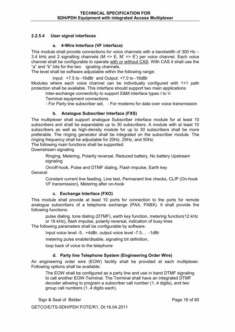
2.2.5.4 User signal interfaces
a. 4-Wire Interface (VF interface) This module shall provide connections for voice channels with a bandwidth of 300 Hz – 3.4 kHz and 2 signalling channels (M => E, M’ => E’) per voice channel. Each voice channel shall be configurable to operate with or without CAS. With CAS it shall use the “a” and “b” bits for the two �ignaling channels. The level shall be software adjustable within the following range:
• Input: +7.5 to -16dBr and Output: +7.0 to -16dBr Modules where each voice channel can be individually configured with 1+1 path protection shall be available. This interface should support two main applications
• Inter-exchange connectivity to support E&M interface types I to V. • Terminal equipment connections
- For Party line subscriber set, - For modems for data over voice transmission
b. Analogue Subscriber Interface (FXS) The multiplexer shall support analogue Subscriber interface module for at least 10 subscribers and shall be expandable up to 30 subscribers. A module with at least 10 subscribers as well as high-density module for up to 30 subscribers shall be more preferable. The ringing generator shall be integrated on the subscriber module. The ringing frequency shall be adjustable for 20Hz, 25Hz, and 50Hz. The following main functions shall be supported: Downstream signaling
• Ringing, Metering, Polarity reversal, Reduced battery, No battery Upstream signaling
• On/off-hook, Pulse and DTMF dialing, Flash impulse, Earth key General:
• Constant current line feeding, Line test, Permanent line checks, CLIP (On-hook VF transmission), Metering after on-hook
c. Exchange Interface (FXO) This module shall provide at least 10 ports for connection to the ports for remote analogue subscribers of a telephone exchange (PAX, PABX). It shall provide the following functions:
• pulse dialing, tone dialing (DTMF), earth key function, metering function(12 kHz or 16 kHz), flash impulse, polarity reversal, indication of busy lines
The following parameters shall be configurable by software: • Input voice level -5.. +4dBr, output voice level -7.5… -1dBr • metering pulse enable/disable, signaling bit definition, • loop back of voice to the telephone
d. Party line Telephone System (Engineering Order Wire) An engineering order wire (EOW) facility shall be provided at each multiplexer. Following options shall be available:
• The EOW shall be configured as a party line and use in band DTMF signaling to call another EOW-Terminal. The Terminal shall have an integrated DTMF decoder allowing to program a subscriber call number (1..4 digits), and two group call numbers (1..4 digits each).

TECHNICAL SPECIFICATION FOR SDH/PDH Equipment with integrated Access Multiplexer
Sign & Seal of Bidder
GETCO/E/TS-SDH/PDH FOTE/R1, Dt:16.04.2011
Page 17 of 60
• EOW based on Voice over IP (VoIP). The EOW traffic shall be routed over the management channel.
e. Data Interfaces Following interfaces shall be available for both Synchronous and asynchronous data transmission:
• V.24/V.28, V.11/X.24, V.35, RS485 and shall support following bit rates : • Synchronous and asynchronous: 0.6 … 38.4kbit/s• Synchronous: 48, 56, N x 64kbit/s (n = 1 … 31)
Following options shall be available:• 1+1 path protection, Sub rate multiplexing, Point-Multipoint, Performance
Monitoring
f. 64kbit/s Co-directional Interface This module shall comply with the ITU-T G.703 part 1.2.1 for co-directional data transfer. Each interface of module can be individually configured with 1+1 path protection shall be available.
g. IP/Ethernet Interface Ethernet module shall comply with the following specification:
• Ethernet electrical connection: 10/100BaseT • Ethernet optical connection: 100Base-FX and 1000Base-LX/SX• Switching: bypass mode for IEEE Std 802.3 frame or based on port or VLAN tag ID • This module shall provide WAN connectivity of VC-12 or VC- 3 and also support
configuration of Logical WAN port. • Framing: According General Framing Procedure (GFP) ITU-T G.7041 • Capacity: Virtual Concatenation (VCAT) acc. ITU-T G.707 • Protection: Link Capacity Adjustment Scheme (LCAS) acc. ITU-T G.7042
Additionally a module with an integrated Ethernet Router shall be available with following function:
• Ethernet connection: Minimum 10BaseT • Routing Protocols: Static IP route, OSPF2 V2 • WAN protocols: PPP • WAN capacity: N x 64kbit/s (n=1 to31) • WAN-ports: > 30
h. Alarm Interface This module shall provide means to collect minimum 8 external alarms, which shall be displayed on the Network Management System. It shall be used to supervise external equipment by the Network Management System. Minimum 4 outputs, which can be switched by the Network Management System. It shall be possible to connect an input to an output so that if an alarm occurs, the output contact will be switched.

TECHNICAL SPECIFICATION FOR SDH/PDH Equipment with integrated Access Multiplexer
Sign & Seal of Bidder
GETCO/E/TS-SDH/PDH FOTE/R1, Dt:16.04.2011
Page 18 of 60
It shall be possible to label an alarm. The label-text shall be read from the interface module so that it can be indicated on the Network Management System as well as on the local craft terminal.
I Module to transmit Protection Commands (For distance protection scheme) This module shall support the following features related to the protection commands:
• Transmit 4 protection commands bi-directionally (i.e. Transmit/receive independently). • All 4 commands Transmit/receive independently such that in case of all four commands
if transmitted from one end then all four will be received to opposite end. • Accept protection command signals in the range of 24VDC … 250VDC • All inputs and outputs shall be isolated and with EMC immunity for harsh environment. • Security and Dependability shall be selectable and programmable.
It shall also be able to drop and insert commands, transfer commands as a transit station and to realize AND- and OR-combinations between commands. The module shall support T-node configurations. The teleprotection module shall provide
• an integrated non-volatile event-recorder, which shall synchronized either internally or by Global Positioning System (GPS)
• A command counters (Digital display type) which counts trip Send/Receive commands with circuitry to store the counts, voltage selection jumper (48V,110V & 220V) or with selectable voltage range & arrangement to reset the counter on the front counter panel shall be provided.
• The teleportection interface (comply with IEC 60834-1) shall allow the protection scheme i.e. permissive tripping, Direct tripping, blocking/Unblocking etc.
The teleprotection module shall further support: • Signal delay measurement • 1+1 protection, switching shall be done within less than 4ms (typical value) • Periodically automatically initiated loop-tests (e.g. every 60s). • Command addressing: This function shall be used to prevent tripping if the
signal is inadvertently re-routed through the telecommunication network Under no circumstances will the module cause trip-commands in case of power supply failure or when equipment is put into or taken out of service.
j Module to interface directly with Protection Relays (Optical interface) This module shall have optical ports each of them allowing direct connection to protection relays with interfaces complying with ANSI/IEEE C37.94. Each interface shall support all 12 time slots (12x 64kbit/s) in accordance with ANSI/IEEE C37.94.
K. Module for transmission of Binary Signals This interface shall provide means to transmit binary signals and support the following features:
• Isolated inputs and outputs (I/O) • Accepting I/O for 24 … 60VDC. • Outputs shall be solid-state relays. • The interface shall provide a 24VDC auxiliary power supply, short circuit proof.

TECHNICAL SPECIFICATION FOR SDH/PDH Equipment with integrated Access Multiplexer
Sign & Seal of Bidder
GETCO/E/TS-SDH/PDH FOTE/R1, Dt:16.04.2011
Page 19 of 60
l. 2Mbit/s Interface according to ITU-T G.703 and G.704 This module shall comply with the ITU-T G.703 / G.704 recommendations and also allow transparent 2Mbit/s signals complying with G.703. The module shall have 2Mbit/s interfaces, each of which may be individually activated. Features:
• Impedance of 120 ohms and 75 ohms • Supporting CRC-4 multi-frame according to ITU-T G.704 (enabled and disabled
by software). • The CAS signaling according to ITU-T G.704 table 9 shall be activated
optionally. • 2Mbit/s loop-back of the incoming signal as well as the loop-back of the internal
signals. The interface shall be able to extract the 2.048MHz clock for synchronization of the multiplex equipment. The interface module shall support 2.2.5.5 System Capacity (To be Supported):
Equipment supplied for the system shall be sized and equipped with sufficient capacity to support BOQ and shall require to support the capacity as specified here under. The system supplied shall be sized (to be equipped as specified) to support full system expansion. Data communications channelization required to support the NMS specified in Technical Specifications (TS) are not identified in the appendices. Therefore, the Contractor is required to size and equip the system to include all channelization and channel cards required to support the NMS function. DESCRIPTION : Capacity GENERAL: Type of multiplexer SDH: ADM Complying to ITU-T rec. Yes Transmission Capacity/Ports STM-4 STM-4 STM-1 STM-1
Mbit/s Ports Mbit/s Ports
622 8
155 16
Access capacity on 64kbit/s channels Minimum 200 Access capacity on 2Mbit/s channels Minimum 40 Redundant central processor Shall be available Digital cross connect function Fully non-blocking PDH cross connect capacity Minimum 40x2Mbit/s SDH cross connect capacity, high order Minimum 4x VC4 Equipment used in substation environment List of 10 reference
substation projects The equipment is KEMA/NABL accredited lab type tested YES

TECHNICAL SPECIFICATION FOR SDH/PDH Equipment with integrated Access Multiplexer
Sign & Seal of Bidder
GETCO/E/TS-SDH/PDH FOTE/R1, Dt:16.04.2011
Page 20 of 60
DESCRIPTION : Capacity Teleprotection interface: Integrated distance teleprotection interface YES Integrated optical teleprotection interface YES Addressing of protection commands YES Loop test for measuring delay time YES 1+1 switch-over less than 10ms YES TRANSPORT LEVEL: Interfaces: Optical STM-4 interface supported YES Optical STM-1 interface supported YES SDH based on SFP technology YES Electrical SDH interface YES Optical 8Mbit/s interface Yes HDB3, 2Mbit/s interfaces per module No. Minimum 8 Complying to ITU-T rec. G.703, transparent
G.704, selectable DSL interface: DSL type / line code G.SHDSL 2Mbit/s: Number of copper wires number 4 or 2 USER INTERFACES Voice module for trunk lines: 1+1 com path protection, individually programmable YES Analogue, 4wire with E&M: Input level / Output level dBr +9.5 to –16 / +7.0 to –16.5 Analogue, 2wire with E&M: Input level / Output level dBr +9.5 to –12.5 / –1.0 to -20 Digital, 2Mbit/s CAS or PRI YES Minimum number of ports/interface number 8 ports Voice interfaces for remote subscriber: 2wire, subscriber side dBr -5 … +4 / -7.5 ... -1 Minimum number of subscriber No. 10 2wire, PABX side dBr -5 … +4 / -7.5 ... -3 Minimum number of PABX ports/interface number 10 ports Integrated teleprotection Interface for Commands Tx/Rx for DPS: 4 Commands/interface Number of independent commands Min. Max.
number 4 Commands 32 Commands
Transmission time max. ms 6 Protection voltage max. VDC 250 1 + 1 com path protection YES Digital Display type counter module to count Tx & Rx command operation for each command with count storage circuitry , Selectable working Voltage 48V/110V/220V and with arrangement on front of module to reset counter (Tx & Rx) for each command separately.
YES

TECHNICAL SPECIFICATION FOR SDH/PDH Equipment with integrated Access Multiplexer
Sign & Seal of Bidder
GETCO/E/TS-SDH/PDH FOTE/R1, Dt:16.04.2011
Page 21 of 60
DESCRIPTION : Capacity Interface(s) for Differential Protection:Optical interface C37.94 Mbit/s 2.048 Minimum Ports/interface Number 4 ports Payload for protection relay kbit/s 64 – 768 Data module V.24/V.28 (RS-232) minimum ports/interface number 4 ports V.11/X.24 (RS-422) minimum ports/interface number 4 ports V.35 minimum ports/interface number 4 ports Integrated Ethernet port available on DATA Interface
YES
SW-programmable board available to assign different types of data interface to each port.
YES
Functions available for individual configuration: - 1+1 path protection - point-multipoint - performance monitoring available for all data interface
YES YES YES YES
Ethernet module Ethernet A: 10/100BaseT 1000Base LX/SX L2 switching function WAN capacity Logical WAN ports GFP (acc. ITU-T G.7041) VCAT (acc. ITU-T G.707) LCAS (acc. ITU-T G.7042)
ports
Mbit/s ports
4x RJ45 electrical 2x optical
YES 63x VC12 or 3x VC3
Minimum 8 Yes
On VC-12 and VC-3 Yes
Ethernet B: min 10BaseT L3 Routing function Routing protocols
WAN capacity, minimum
WAN ports WAN protocol
ports
ports
1x RJ45 YES
static IP routing OSPF2 V2 2x 2Mbit/s
(64kbit/s granularity) > 30
PPP, HDLC Ethernet C: Power over Ethernet ports Min. 6x RJ45 Integrated alarm gathering module: Number of external alarms per module number 8 alarms / module Auxiliary power supply for ext. contacts YES CONFIGURATION TOOL: Type/Name of configuration tool
For local / remote operation YES / YES Data communication network (DCN) Ethernet / IP Integrated Management of
Teleprotection Command module YES

TECHNICAL SPECIFICATION FOR SDH/PDH Equipment with integrated Access Multiplexer
Sign & Seal of Bidder
GETCO/E/TS-SDH/PDH FOTE/R1, Dt:16.04.2011
Page 22 of 60
DESCRIPTION : Capacity NETWORK MANAGEMENT SYSTEM Type/Name of configuration tool
For fault / configuration management YES / YES Data communication network (DCN) Ethernet / IP or
Ethernet / OSI Management of integrated
Teleprotection Command Module YES
Ambient Conditions: Storage: ETS 300 019-1-1, class 1.2 °C / %
hum - 25 … + 70°C / 98%
Transport: ETS 300 019-1-2, class 2.2 °C / % hum
- 25 ... + 70°C / 98%
Operation: ETS 300 019-1-3, class 3.1E For xDSL, ISDN and IP/Ethernet modules
°C / % hum
- 5 … +55°C / 95% - 5 ... +45°C / 95%
Power Supply Operation VDC 48 / 60 (-15/+20%) Fully redundant power supply YES Dual power feeding YES
The offered equipment shall be complied fully in Toto for system capacity to be supported as specify in Clause (2.2.5.5) above. The bidder shall have to submit undertaking regarding conformity for System capacity in accordance with table at clause (2.2.5.5) above and deviation if any found against your confirmatory document submitted with tender bid, the offer shall be liable to be rejected. 2.2.5.6 SCHEDULE –A1 (A) Table of compliance: Data about offered equipment to be filled in by the bidder. Name of Manufacturer: ______________________________________ Model/Type: ______________________________________
SUPPORTED BY OFFERED SYSTEM(To be filled up by bidder)
GENERAL: Type of multiplexer SDH: ADM Complying to ITU-T rec. Yes/NO Transmission Capacity/Ports: STM-4: 622 Mbit/s STM-4: 8 Ports STM-1: 155 Mbit/s STM-1:16 Ports
Yes/NO Yes/NO Yes/NO Yes/NO

TECHNICAL SPECIFICATION FOR SDH/PDH Equipment with integrated Access Multiplexer
Sign & Seal of Bidder
GETCO/E/TS-SDH/PDH FOTE/R1, Dt:16.04.2011
Page 23 of 60
SUPPORTED BY OFFERED SYSTEM(To be filled up by bidder)
Access capacity on 64kbit/s
Min. channels
Max. channels
Access capacity on 2Mbit/s
Min. channels
Max. channels
Redundant central processor Available YES/NO Digital cross connect function (Fully non-blocking)
YES/NO
PDH cross connect capacity Min. N x 2 Mbit/s Max. N x 2 Mbit/s
N= N=
SDH cross connect capacity, high order Minimum N x VC4 N= Equipment used in substation environment (List of 10 reference substation projects attached)
YES/NO
The equipment is KEMA/NABL accredited Lab type tested
YES/NO
Teleprotection interface: Integrated distance teleprotection interface YES/NO Integrated optical teleprotection interface YES/NO Addressing of protection commands YES/NO Loop test for measuring delay time YES/NO 1+1 switch-over less than 10ms YES/NO TRANSPORT LEVEL: Interfaces: SDH based on SFP technology YES/NO Electrical SDH interface YES/NO Optical 8Mbit/s interface Yes/NO
Electrical interface Yes/NO (If yes then N Mbit/s)
N=
HDB3, 2Mbit/s interfaces per module Minimum N x 2 Mbit/s N= Complying to ITU-T rec. G.703, transparent
G.704, selectable

TECHNICAL SPECIFICATION FOR SDH/PDH Equipment with integrated Access Multiplexer
Sign & Seal of Bidder
GETCO/E/TS-SDH/PDH FOTE/R1, Dt:16.04.2011
Page 24 of 60
SUPPORTED BY OFFERED SYSTEM(To be filled up by bidder)
DSL interface: DSL type / line code G.SHDSL 2Mbit/s: Number of copper wires 4 or 2 64kbit/s channels: Capacity on 2Mbit/s or 1Mbit/s Available If Yes
Capacity selectable If Yes
YES/NO
Channels (2 Mbit/s) : Channels (1 Mbit/s) :
YES/NO
channels / pair of wire
____ / 2 pairs &
____ / 1 pair
USER interfaces Voice interfaces for trunk lines: Minimal number of Ports/interface Number ‘N’ N= 1+1 com path protection, individually programmable
YES/NO
Analogue, 4wire with E&M: Input level dBr Output level dBr
Analogue, 2wire with E&M:
Input level dBr Output level dBr
Digital, 2Mbit/s CAS or PRI Available YES/NO Voice interfaces for remote subscriber: 2wire, subscriber side (FXS) dBr Minimal number of PABX (FXS) Number ‘N’ N= 2wire, PABX side (FXO) dBr Minimal number of PABX (FXO) Number ‘N’ N=

TECHNICAL SPECIFICATION FOR SDH/PDH Equipment with integrated Access Multiplexer
Sign & Seal of Bidder
GETCO/E/TS-SDH/PDH FOTE/R1, Dt:16.04.2011
Page 25 of 60
SUPPORTED BY OFFERED SYSTEM (To be filled up by bidder)
Integrated teleprotection Interface for Commands Tx/Rx for DPS : Minimum No. of independent commands/interface Number ‘N’ N= Number of independent commands Minimum 4 Nos.
Maximum 32 Nos.
Transmission time max. 6 ms Signal voltage Max VDC 1 + 1 com path protection YES/NO Digital Display type counter module to count Tx & Rx command operation for each command with count storage circuitry , Selectable working Voltage 48V/110V/220V and with arrangement on front of module to reset counter (Tx & Rx) for each command separately.
YES/NO
Data: interfaces per module V.24/V.28 (RS-232) Number ’N’ N= V.11/X.24 (RS-422) Number ’N’ N= V.35 Number ’N’ N= Integrated LAN port available on DATA Interface YES/NO Software programmable board available YES/NO Functions available for individual configuration: - 1+1 path protection - point-multipoint - performance monitoring - sub rate multiplexing available for all data interface
YES/NO YES/NO YES/NO YES/NO YES/NO
Ethernet interface Ethernet A: 10/100BaseT ports 1000Base LX/SX ports L2 switching function WAN capacity Mbit/s Logical WAN ports ports GFP (acc. ITU-T G.7041) VCAT (acc. ITU-T G.707) LCAS (acc. ITU-T G.7042)
4x RJ45 electrical 2x optical YES/NO
N x VC12 or N’ x VC3Minimum N’’=
Yes/NO On VC-12 and VC-3
Yes/NO
N= & N’= N’’=
TECHNICAL SPECIFICATION FOR SDH/PDH Equipment with integrated Access Multiplexer
Sign & Seal of Bidder
GETCO/E/TS-SDH/PDH FOTE/R1, Dt:16.04.2011
Page 26 of 60
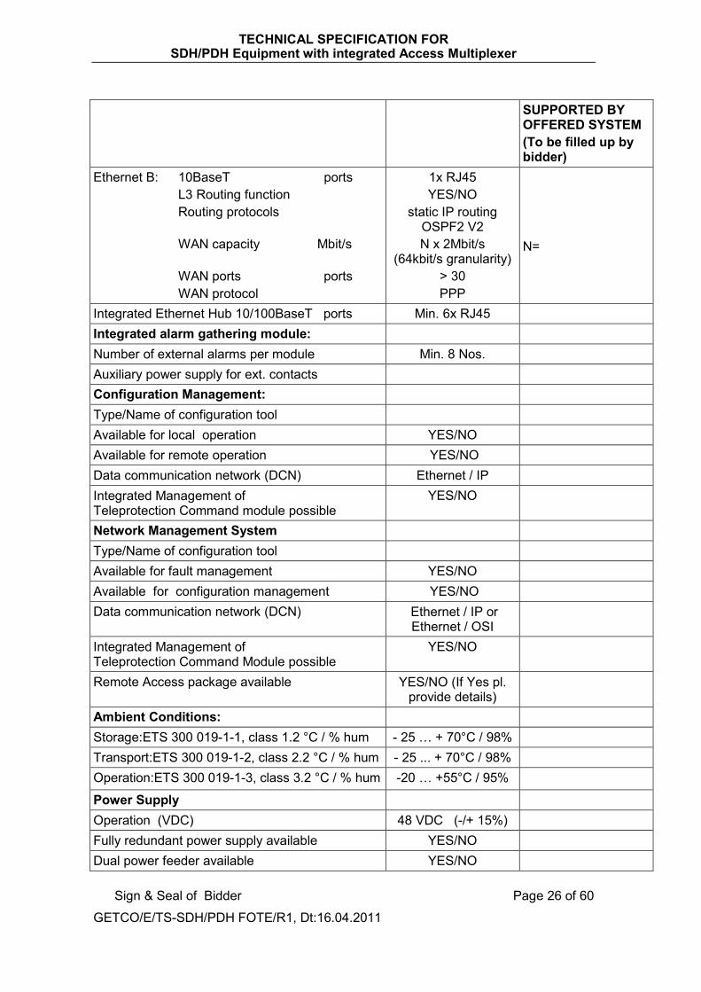
SUPPORTED BY OFFERED SYSTEM (To be filled up by bidder)
Ethernet B: 10BaseT ports L3 Routing function Routing protocols
WAN capacity Mbit/s
WAN ports ports WAN protocol
1x RJ45 YES/NO
static IP routing OSPF2 V2 N x 2Mbit/s
(64kbit/s granularity) > 30 PPP
N=
Integrated Ethernet Hub 10/100BaseT ports Min. 6x RJ45 Integrated alarm gathering module: Number of external alarms per module Min. 8 Nos. Auxiliary power supply for ext. contacts Configuration Management: Type/Name of configuration tool Available for local operation YES/NO Available for remote operation YES/NO Data communication network (DCN) Ethernet / IP Integrated Management of Teleprotection Command module possible
YES/NO
Network Management System Type/Name of configuration tool Available for fault management YES/NO Available for configuration management YES/NO Data communication network (DCN) Ethernet / IP or
Ethernet / OSI
Integrated Management of Teleprotection Command Module possible
YES/NO
Remote Access package available YES/NO (If Yes pl. provide details)
Ambient Conditions: Storage:ETS 300 019-1-1, class 1.2 °C / % hum - 25 … + 70°C / 98%Transport:ETS 300 019-1-2, class 2.2 °C / % hum - 25 ... + 70°C / 98% Operation:ETS 300 019-1-3, class 3.2 °C / % hum -20 … +55°C / 95%
Power Supply Operation (VDC) 48 VDC (-/+ 15%) Fully redundant power supply available YES/NO Dual power feeder available YES/NO

TECHNICAL SPECIFICATION FOR SDH/PDH Equipment with integrated Access Multiplexer
Sign & Seal of Bidder
GETCO/E/TS-SDH/PDH FOTE/R1, Dt:16.04.2011
Page 27 of 60
(B) CONFIGURATION OF DIFFERENT MODULES AVAILABLE WITH OFFERED SYSTEM
Sr. No.
Name of Module Name of Interface No. of Port Available per
Interface
Max. No. of Interface
supported by the system
offered 1. SDH Modules a) STM – 4
(622 Mbit/s) b) STM – 1 (155 Mbit/s)
Optical : Optical : Electrical :
2. PDH Modules a) 8 Mbit/s
b) 2M bit/s(G.703)
Optical : 1310nm Optical : 1550nm Electrical :
3. DSL Trunk Modules DSL Interface (2 Mbit/s)
2 Pair Copper Wire : 1 Pair Copper Wire :
4. VF Modules 6 W Interface (4W for Tx & Rx and E wire, M Wire)
E&M Trunks :
5. Analogue subscriber Module
FXS a) Min. configuration b) High density
Subscriber : Subscriber :
6. Exchange Interface Module
FXO a) Min. configuration : b) High density :
Subscriber :
Subscriber :
7. Data Interface Modules
a) V.24 / V.28 (RS232) b) V.24/V.11 (RS422)(NX64bit/s) c) (RS485)
8. 64K bit Co-directional Interface Module
64 Kbit/s Co-directional Interface (comply with ITU-T G.703 Part 1.2.1)

TECHNICAL SPECIFICATION FOR SDH/PDH Equipment with integrated Access Multiplexer
Sign & Seal of Bidder
GETCO/E/TS-SDH/PDH FOTE/R1, Dt:16.04.2011
Page 28 of 60
Sr. No.
Name of Module Name of Interface No. of Port Available per
Interface
Max. No. of Interface
supported by the system
offered 9. IP/Ethernet
Interface Module IP/Ethernet Interface
•10/100 Base T
•100 Base – FX
•1000 Base-LX/SX
•WAN capacity
Electrical : Optical :
Optical : VC – 12 : VC – 3 : Logical WAN (LWP) :
10. IP/Ethernet Module With integrated Ethernet Router
Ethernet• 10 Base T
• WAN capacity
(NX64K bit/s) • WAN ports
Electrical: N=
11. Teleprotection Commands module
c) Teleprotection Relay interface (Electrical)
d) Teleprotection Relay interface (Optical)
No. of independent Commands transmit bidirectional : Optical Ports:
12. Module for Trans- mission of Binary signals
Binary signals Interface
Isolated I/Ps: Isolated O/Ps:
13. Module for 2Mbit/s Interface
Interface comply With the ITU-T G.703/G.704 (NX2 Mbit/s)
N =

TECHNICAL SPECIFICATION FOR SDH/PDH Equipment with integrated Access Multiplexer
Sign & Seal of Bidder
GETCO/E/TS-SDH/PDH FOTE/R1, Dt:16.04.2011
Page 29 of 60
2.2.5.7 SCHEDULE- B1
LIST OF TYPE TEST REPORTS FOR SDH equipment with integrated Access Multiplexer. :
(a) Emission of the equipment (substation environment)
No Test Name Description Basic standard 1.1 Radiated radio frequency interference 30 MHz to 1 GHz EN 55022 1.2 Conducted radio frequency interference AC/DC
Power supply 150 kHz to 30 MHz EN 55022
(b) Immunity of the equipment (substation environment)
No Test Name Description Basic standard2.1 ESD test Contact/air discharge IEC 61000-4-2 2.2 Radiated
electromagnetic field 80 to 1000 MHz, 80% AM, 1 kHz modulated IEC 61000-4-3
2.3 Radiated electromagnetic field
1.0 to 2.5 GHz, 80% AM, 1 kHz modulated IEC 61000-4-3
2.4 Fast transient test AC/DC Power supply: all other ports:
IEC 61000-4-4
2.5 Surge test (1.2/50 µs) AC/DC Power supply:Common mode Differential mode DC Power supply 48 V:Common mode Differential mode Signal terminals:Common mode Differential mode Telecommunication ports:Common mode
IEC 61000-4-5
2.6 Conducted radio frequency interference
0.15 to 80 MHz, 80% AM, 1kHz modulated
IEC 61000-4-6
2.7 Power frequency magnetic field
Continuous Short (1 to 3 s)
IEC 61000-4-8
2.8 Damped oscillatory waves
AC/DC Power supply:Common mode Differential mode Signal terminals:Common mode Differential mode Telecommunication ports:Common mode 1 MHz, 400 Hz repetition rate, 2 s burst duration
IEC 61000-4-12
2.9 Conducted common mode disturbance
Frequency 50 Hz, continuous mode IEC 61000-4-16

TECHNICAL SPECIFICATION FOR SDH/PDH Equipment with integrated Access Multiplexer
Sign & Seal of Bidder
GETCO/E/TS-SDH/PDH FOTE/R1, Dt:16.04.2011
Page 30 of 60
( c ) Emission of the equipment (substation environment)
No Test Name Description Basic standard
Class Comply (To be filled up by
bidder) 1.1 Radiated radio
frequency interference
30 MHz to 1 GHz EN 55022 A
1.2 Conducted radio frequency interference AC/DC Power supply
150 kHz to 30 MHz EN 55022 A
( d ) Immunity of the equipment (substation environment)
No Test Name Description Basic standard
Level Comply (To be filled up by
bidder) 2.1 ESD test Contact/air discharge IEC 61000-4-2 6 / 8kV 2.2 Radiated
electromagnetic field80 to 1000 MHz, 80% AM, 1 kHz modulated
IEC 61000-4-3 10V/m
2.3 Radiated electromagnetic field
1.0 to 2.5 GHz, 80% AM, 1 kHz modulated
IEC 61000-4-3 10V/m
2.4 Fast transient test AC/DC Power supply: all other ports:
IEC 61000-4-4 4kV 2kV
2.5 Surge test (1.2/50 µs)
AC/DC Power supply:Common mode Differential mode DC Power supply 48 V:Common mode Differential mode Signal terminals:Common mode Differential mode Telecommunication ports:Common mode
IEC 61000-4-5 2.0kV 1.0kV
0.5kV 0.5kV
2.0kV 1.0kV
1.5kV
2.6 Conducted radio frequency interference
0.15 to 80 MHz, 80% AM, 1kHz modulated
IEC 61000-4-6 10V/m (e.m.f.)
2.7 Power frequency magnetic field
Continuous Short (1 to 3 s)
IEC 61000-4-8 30 A/m 300 A/m

TECHNICAL SPECIFICATION FOR SDH/PDH Equipment with integrated Access Multiplexer
Sign & Seal of Bidder
GETCO/E/TS-SDH/PDH FOTE/R1, Dt:16.04.2011
Page 31 of 60
No Test Name Description Basic standard
Level Comply (To be filled up by
bidder) 2.8 Damped oscillatory
waves AC/DC Power supply:Common mode Differential mode Signal terminals:Common mode Differential mode Telecommunication ports:Common mode 1 MHz, 400 Hz repetition rate, 2 s burst duration
IEC 61000-4-122.50kV 1.25kV
2.50kV 1.25kV
2.50kV
2.9 Conducted common mode disturbance
Frequency 50 Hz, continuous mode
IEC 61000-4-16 10 / 30 Vrms
The bidder shall have to comply for all the details asked under Clause 2.2.5.6 (A) & (B) and 2.2.5.7 (c ) and (d) against each items of tables given above invariably. In case of non-submission of same with the offer, the bid shall be liable to be rejected. 2.2.5.8 Redundancy Requirements and Protection Schemes Equipment redundancy and Automatic Protection Schemes (APS) are specified in the Table 2-1. The failure of one element shall not prevent the use of any other that has not failed.
Table 2.1 Equipment Redundancy Requirements Summary
Fibre Optic terminal equipment : SDH STM-1 ADM Power Supply & Converters Common Control* Cards * = Common control cards which are essentially required for operation of the equipment.
APS APS
The offered equipment shall support at least SNCP as per standard ITU-T G.841. In case the equipment offered by the Bidder does not support the above mentioned minimum protection methods, the bidder shall have to provide all additional equipment needed to provide same level of flexibility, redundancy and functionality at no additional cost to Employer. The bidders shall provide details of protection schemes supported in the Bid document. The offered equipment shall support automatic switchover function between the redundant modules and all required modules and hardware to support the automatic switch over shall be provided by the Contractor.
TECHNICAL SPECIFICATION FOR SDH/PDH Equipment with integrated Access Multiplexer
Sign & Seal of Bidder
GETCO/E/TS-SDH/PDH FOTE/R1, Dt:16.04.2011
Page 32 of 60
2.2.5.9 Lost Signal Recovery At any digital signal level, reapplication of a lost signal shall result in automatic resynchronization and full restoration to normal operation without manual intervention. All alarms incident to the signal failure, shall be automatically cleared at the equipment, rack and monitoring levels and normal operation indications restored and reported if applicable. 2.2.5.10 Equipment Life span All equipment supplied shall have a minimum expected life of fifteen (15) years from the date of operational acceptance. 2.2.5.11 Revision Levels and Modifications All hardware, firmware and software delivered as part of the communications network shall be field proven and at the most of current revision level. All modifications and changes necessary to meet this requirement shall be completed prior to the start of the factory tests or under special circumstances, on written approval of GETCO, prior to the completion of SAT. All field modifications of the hardware, firmware and software that is required to meet installation and/or performance specifications, shall be fully documented as part of the deliverables, both as a separate field modifications record and as corrected equipment/configuration documentation. 2.3 Fibre Optics (OPGW) Network System The network of Fibre Optics (OPGW) for transmission lines and connecting substation covered under the project is enclosed in separate sheet: Network Layout.
2.3.1 General Site Considerations All fiber optic links up to 260 kms transmission line route length shall be implemented by the Contractor without repeaters. In order to meet the link budget requirement, the Contractor shall provide all the necessary equipments only in the end stations. The contractor may provide the optical amplifier, wave length translator, optical cards to meet the maximum distance limit. All the provided equipments shall be monitored by centralized NMS. 2.3.2 Proposed Optical Fibre Characteristics The characteristics of the fibre(s) being installed under separate package are provided in the table 2-1(a): 2.3.3 Fibre Optic Link Lengths The fiber optic route lengths is specified in Annexure-A. The lengths specified in appendices are the transmission line route lengths; however the actual fiber cable length shall exceed the route lengths on account of extra cable requirement due to sag, jointing & splicing, approach cabling etc. For bidding purposes the Contractor may assume an additional cable length of 5% of given route length + 1Km towards approach cable for calculating the link length. The exact cable lengths shall be determined by the Fibre Optic cable package Contractor during the survey. The same

TECHNICAL SPECIFICATION FOR SDH/PDH Equipment with integrated Access Multiplexer
Sign & Seal of Bidder
GETCO/E/TS-SDH/PDH FOTE/R1, Dt:16.04.2011
Page 33 of 60
shall be forwarded to this package Contractor for final link design during the detailed engineering of the project. In case of change in the specified BOQ, the contract price shall be adjusted accordingly.
2.3.4 Redundancy and Protection Fibre rings shall be implemented wherever the network permits (Network diagram enclosed). On linear sections of the network, protected links using 4 fibres shall be implemented.

TECHNICAL SPECIFICATION FOR SDH/PDH Equipment with integrated Access Multiplexer
Sign & Seal of Bidder
GETCO/E/TS-SDH/PDH FOTE/R1, Dt:16.04.2011
Page 34 of 60
2.3.5 Supervision and Alarms ISM (In Service Monitoring) circuitry shall be provided as a function of the SDH equipment. Local visual alarm indicators (LEDs) shall be provided on each module. As a mandatory functional requirement, Loss of signal (LOS) alarm LED indication shall be provided on the OLTE module of the SDH equipment. There shall also be separate LED indication for hardware failure on each module. Alarms shall be as per ITU-T Standards G.774, G.783 and G.784. Additionally, F/Q1 interfaces for a local craftsperson terminal interface and remote equipment monitoring is required. The Equipment shall support collection of at least four (4) external alarms for monitoring and control of station associated devices by the NMS. 2.3.6 Synchronisation The equipment shall provide synchronization as per Table 2-2. One 2MHz synchronization output from each equipment shall be provided. 2.3.7 Electrical and Optical I/O Characteristics and General Parameters Table 2-2 provides the electrical and optical characteristics as well as other general parameters for SDH equipment.
NOTE (1) Optical wavelength shall be selected considering the characteristics of the Optical fibre (OPGW) and the link budget.

TECHNICAL SPECIFICATION FOR SDH/PDH Equipment with integrated Access Multiplexer
Sign & Seal of Bidder
GETCO/E/TS-SDH/PDH FOTE/R1, Dt:16.04.2011
Page 35 of 60
NOTE (2) Eye Safety for Laser Equipment: To avoid eye damage, when a receiver detects a line interruption, it is required that the optical power of the laser shall be reduced to safe limits on the transmitter in the opposite direction as per ITU-T G.958. NOTE (3) In case other than FC-PC connector is provided in the equipment suitable patch cords with FC-PC connector are to be provided to connect with FODP. 2.3.8 Optical Link Performance Requirements The optical fibre link performance requirements are specified as follows: 2.3.8.1 Link Budget Calculations The fibre optic link budget calculations shall be calculated based upon the following criteria: (1) Fibre attenuation: The fibre attenuation shall be taken to be the guaranteed
maximum fibre attenuation i.e. 0.21 dB/Km @1550nm and 0.35 dB/km @1310nm. (2) Splice loss: Minimum 0.05 dB per splice. One splice shall be considered for every 3
kms. (3) Connector losses: Losses due to connectors shall be considered to be minimum 1.0
dB per link. (4) Equipment Parameters: The equipment parameters to be considered for link budget
calculations shall be the guaranteed “End of Life (EOL)” parameters. In case, the End of Life parameters are not specified for the SDH equipment, an End of Life Margin of at least 2 dB shall be considered and a similar margin shall be considered for optical amplifiers.
(5) Optical path Penalty: An optical path penalty of at least 1 dB shall be considered to account for total degradations due to reflections, inter symbol interference, mode partition noise and laser chirp.
(6) Maintenance Margin: A maintenance margin of at least 2.5 dB/100Km shall be kept towards cabling, repair splicing, cable ageing and temperature variations etc.
(7) Other losses: Other losses, if any required specifically for system to be supplied shall also be suitably considered.
(8) Dispersion: The fibre dispersion shall be taken to be the guaranteed maximum dispersion i.e. 18 ps/nm.Km @1550 nm & 6 ps/nm.km @ 1310 nm for DWSM fibres.
(9) Bit Error Rate: The link budget calculations shall be done for a BER of 10-10
.
The bidders shall determine the total link loss based on the above parameters and shall submit the system design (including link budget calculations as per Table 2.3 (I)) for each category of fibre optic link in the Bid. For finalising the FOTE system design & BOQ, above methodology shall be adopted taking into account fibre attenuation, dispersion and splice loss determined during the detailed engineering. Accordingly, additions and deletions from the contract shall be carried out based on unit rates indicated in the contract.

TECHNICAL SPECIFICATION FOR SDH/PDH Equipment with integrated Access Multiplexer
Sign & Seal of Bidder
GETCO/E/TS-SDH/PDH FOTE/R1, Dt:16.04.2011
Page 36 of 60
Table 2.3 (I) SDH Equipment
Fibre Optic Link Name
Link Losses (dB) Sl. No.
From To
OPGW Cable length (Km)
OPGW Cable length (Km)
(+5% + 1km)
SFP Type
0.22dB/Km loss at
1550nm
0.35dB/Km loss at
1310nm
Splice loss @ 0.05dB
per splice
per 3KM
Connector loss (dB)
Optical Path
penalty (dB)
Maintenance Margin
@0.025dB/Km
Total loss
Tx power End Of
Life(dBm)
Rx Sensitivity (dBm)
Available
Power (dB)
Received
Power (dB)
Margin for
future (dB)
2.3.8.2 Link Performance The Link performance for ES, SES and BER for the fibre optic links shall correspond to National Network as defined in ITU-T G.826.
2.3.8.3 FODP to SDH Equipment/Optical Amplifier Connectivity The Contractor shall be responsible for connectivity between the FODP and the SDH equipment. The Contractor shall provide FC PC coupled patch cords. The location of FODP shall be finalized during detailed engineering. The patch-cord length between the FODP & equipment rack shall be suitably protected from rodents, abrasion, crush or mechanical damage. 2.4 MDF, DDF and Cabling For the purposes of the specification, the contractor shall provide cabling, wiring, DDF patching facilities and MDFs interfacing to the wideband telecommunications system. Equipment and material components for MDF, DDF and cabling are also part of this procurement. It shall be the Contractor's responsibility to provide all cable support required for full supplied equipment interconnection with the MDF and shall be in accordance with communications industry standard practices and the requirements mentioned in the technical specifications.
2.4.1 MDF and DDF Patching Facilities The Contractor shall supply and install all cabling, wiring, connectors, cross connects, Digital Distribution Frames (DDF) and Main Distribution Frames (MDF) associated with the installation and interconnection of equipments procured under this package,
(i) DDFs for termination of V.24/V.28 ports with DB25 connectors. (ii) MDFs for termination of all the E&M subscriber channels on Krone IDC blocks.
All subscriber channels shall be provided with GD tubes. (iii) Cabling and connectors required to enable subscriber-to-subscriber circuits over the telecom network. The Line side of the MDF shall be cabled to the Primary
Multiplex and the equipment side shall be cabled to the MDF of the assigned subscriber (PLCC, PABX, Telephone at wideband locations etc).
(vi) Any other cables, connections etc required for a fully functional, integrated telecom system.

TECHNICAL SPECIFICATION FOR SDH/PDH Equipment with integrated Access Multiplexer
Sign & Seal of Bidder
GETCO/E/TS-SDH/PDH FOTE/R1, Dt:16.04.2011
Page 37 of 60
The connections amongst various equipment such as FOTE and subscriber MDFs etc shall always be routed through DDF and MDF to provide maintenance access. 2.5 Patch Cords The Contractor has to supply FC PC coupled Patch cords as described in BOQ. The Patch cord return loss shall be equal to or better than 40 dB and insertion loss equal to or less than 0.5 dB. 2.6 Network Management System The Bidder shall provide a Network Management System (NMS) for operational support to the FOTE. This NMS shall provide the capability to monitor, reconfigure, and control elements of the telecommunications network from a centralized location (RLDC) as well as at remote operation location (SLDCs) and at each node of the network (through craft terminal) where equipment is located. Network management is crucial for the overall performance and availability of the communication network. The task of the network management system (NMS) is to provide complete and efficient supervision of the alarm state of the network (fault management), to facilitate the adaptation of the configuration to changing needs (configuration management) and to strictly control the access to the various NMS features (security management). 2.6.1 Applicable Standards The NMS design concept, functional and informational architecture and physical architecture, shall be in compliance with ITU-T Recommendation M.3010.
2.6.2 NMS Architecture a) The Network Management System (NMS) should be structured according to the
NMS Logical Layered Architecture established in section 5 of ITU-T Recommendation M.3010 (05/96) and cover the Element & Network Management layers of this architecture.
The system should be designed using a client-server paradigm and use a SQL complaint Database to store alarm and configuration data.
Access to the system shall be possible for many users at the same time using NMS Client software. Client software shall be installed on the server machine itself and on separate client PC.
The NMS Server machine shall be located at ALDC Jetpur along with 2 operator consoles. The distance between ALDC Jetpur and 400KV Jetpur is around 300 mtrs. Appropriate convertors/cables/interfaces shall be provided by the bidder to achieve the connectivity between the equipment and the NMS server.
One operator console shall be provided at SLDC Gotri. Ethernet connectivity between ALDC Jetpur and SLDC Gotri shall be provided by GETCO.
b) Platform and Redundancy
The NMS server software should be based on a secure operating system (Linux/Unix). The NMS software with license for managing total nodes of SDH

TECHNICAL SPECIFICATION FOR SDH/PDH Equipment with integrated Access Multiplexer
Sign & Seal of Bidder
GETCO/E/TS-SDH/PDH FOTE/R1, Dt:16.04.2011
Page 38 of 60
STM-1 FOTE: 21 Nos. (Belongs to Group 1 of Network Layout) + 100% additional capacity, graphical network view, 2 concurrent users shall be supplied under this package by the bidder. The NMS server hardware should have dual hard disks configured as a RAID system level 1 (mirroring).
There should be a possibility to add a second NMS server to create a Main/Standby system using an interconnecting link with a minimum bandwidth of 2Mbit/s. The Standby should automatically switch to active mode if it looses contact to the Main. It shall also be possible to operate the two NMS independently if the connection between the two servers is down.
For quick fault recovery and minimum NMS downtime it shall be possible to manually create a backup of the database and store it on the local disk or on a DVDs. A facility should exist to create a bootable backup of the complete system either on tape or DVDs.
c) Supported Network Elements
For ease of management and monitoring by GETCO, the System shall be able to manage all the offered communication equipment (SDH/PDH) and Teleprotection equipment from a single software and hardware.
d) Graphical User Interface
The Graphical User Interface should have definable network displays (maps). Icons symbolizing sub-networks, equipment and links are to be placed on an optional background image and can be opened to display greater details down to equipment port level. Context sensitive menus and online help should be available. It should be possible to create any number of network maps to create different views of the network, e.g. geographical, schematic, sub-network, etc.
The Bidder shall submit for GETCO’s approval the NMS architecture describing in detail the following subsystems/features: a. Database used in NMS b. Master Processor, server/workstation, LAN, Peripherals and hardware c. Software and operating system d. Local Consoles/remote consoles e. Craft Terminals f. Data communication between NEs, Remote/Local Consoles and TMN Processor(s) g. Routers/Bridges h. Expansion Capabilities 2.6.3 Management Functions The NMS shall support following Management functions: 2.6.3.1 Configuration Management Configuration management is concerned with management, display, and control of the network configuration. Minimum specific requirements that shall be satisfied include the following:

TECHNICAL SPECIFICATION FOR SDH/PDH Equipment with integrated Access Multiplexer
Sign & Seal of Bidder
GETCO/E/TS-SDH/PDH FOTE/R1, Dt:16.04.2011
Page 39 of 60
a. Provide tools to establish and maintain the backbone topology and configuration information and provide graphical maps depicting the configurations.
b. Gather descriptive information about the current configuration of the equipment, provide operator displays, and prepare reports.
c. Provide tools for planning, establishing, and changing the static equipment configuration. Provide for changes to the equipment configuration in response to equipment failures, planned upgrades, and operator requests to take equipment offline for testing.
d. Provide verification testing to support new equipment installation.
NMS Configuration A graphical User Interface should exist to create network Domains, the NEs to be managed by the system and NE supervision processes. (Domains are used to structure the network in areas of responsibilities and are used in the definition of access right. The supervision processes allow grouping the NEs for supervision and enabling the supervision of a group of NEs to be turned to ON or OFF.)
NE Configuration Once an NE is discovered by the NMS its configuration shall be automatically uploaded and stored on the NMS hard disk. It shall be possible to configure the NMS to automatically keep a definable number of the most recent NE configurations accessible for inspection and/or download. All NE configuration changes should be done from the NMS using easy to use graphical windows accessible via drop down menus starting from the NE symbol on the graphical network view. The NMS shall fully support the administration of the NE configuration data (upload, download, backup, copy) and the NE embedded software (upgrade).
End to End Circuit/Trail Configuration As an NMS option a facility for automated end-to-end configuration of trails and circuits (trail management) shall be offered including the 64kBit/s cross- connections. The option shall enable the operator to create and maintain database tables containing all the communication services configured into the network. A graphical user interface shall be available to browse, modify or delete the existing end to end connections or to create new ones. To create new connections it shall be sufficient to specify the type of connection, the required bandwidth, the protection type and the two end points. The software should then suggest routes through the network and can be used to automatically download the required cross-connections to all the NEs which belong to the selected route. Trails e.g. at VC4, VC12 or E1 level can be inspected for the number of used/free channels. Various reports shall be printed and information extracted in a format which is suitable to be imported into a spread sheet program such as Excel. 2.6.3.2 Fault Management

TECHNICAL SPECIFICATION FOR SDH/PDH Equipment with integrated Access Multiplexer
Sign & Seal of Bidder
GETCO/E/TS-SDH/PDH FOTE/R1, Dt:16.04.2011
Page 40 of 60
The Network Management System should provide comprehensive and efficient fault management, based on a graphical network view and coloured symbols representing the alarm state of the respective network element.
Fault management is concerned with detecting, diagnosing, bypassing, directing service restoration, and reporting on all the backbone network equipment, systems, and links. Minimum specific requirements that shall be satisfied include the following: a. Display equipment status in a consistent fashion regardless of the source of the
data on a graphical topological, map-type display. Status shall be displayed through the use of colours on links and nodes as well as through text.
b. Obtain status and detect faults through periodic polling, processing of unsolicited alarms and error events, and periodic testing for connectivity.
c. Maintain an alarm summary of unacknowledged alarm events on the management station display and maintain a log of all received alarms. The operator shall be able to acknowledge and clear alarms individually and as a group. The use of alarm correlation techniques is encouraged to minimize the proliferation of alarms caused by a single, common event. All alarms shall be configurable as critical alarms, major alarms and minor alarms with different colours
Additionally the following fault management features are required:
• The NE symbols on the layered network views must have markers to indicate
1. if an NE is reachable,
2. disabled through the operator,
3. has an attached operator note,
4. if there are unacknowledged active alarms (one marker for each severity level),
5. if there are unacknowledged cleared alarms • An Alarm Summary View to display alarm counters per severity • An Alarm List containing all active alarms and all cleared and unacknowledged
alarms. The alarm list should be displayed in a tabular form with extensive filtering possibilities. It must be possible to adjust the size and the order of the displayed columns. Alarms are selectable for operator actions (e.g. acknowledgement) individually or in groups using the mouse and the Ctrl or Shift key.
• New active alarms should appear in the alarm list marked as unacknowledged until they are confirmed by the operator. New cleared alarms must be either marked as unacknowledged or alternatively self-acknowledged by the NMS software. The preferred behavior should be an NMS configuration option.
• For each alarm a detailed alarm view must exist to display all alarm properties including raise and clear times, the time of acknowledgement and the username of the person which performed the acknowledgment. It must be possible to add operator notes for each alarm.
• For external equipment with alarm output contacts (common alarm outputs, door contacts etc.) the fault management should provide an option to display the respective alarm states by coloured symbols on the map.
• Sections (Links - typically fibre optic interconnection between nodes) should be dynamic and displayed in the colour of the most severe alarm of the ports which the link is connected to.

TECHNICAL SPECIFICATION FOR SDH/PDH Equipment with integrated Access Multiplexer
Sign & Seal of Bidder
GETCO/E/TS-SDH/PDH FOTE/R1, Dt:16.04.2011
Page 41 of 60
Synchronization Map Since this is a large network, to facilitate the identification of synchronization problems within the communication network, the NMS should provide a dynamic synchronization view/map. This synchronization view must display the active synchronization sources for every network element using a graphical representation, so the clock distribution in the network can be easily tracked.
2.6.3.3 Security Management Access to the different functional areas of the NMS shall be strictly controlled by the privileges assigned to the individual NMS users. Accounts which shall have access to the NMS must be assigned NMS access rights by an NMS administrator. There shall be one overall NMS administrator which is able to create additional regional administrators which have full control e.g. to assign NMS access rights, but are limited to their domain – corresponding to e.g. a geographical region.
To simplify the task of access right assignments customer specific user profiles can be predefined which then can be assigned the individual NMS users. It should allow to create users which have access rights to several/all domains with a different profile for each domain.
Specifically, the following features must be individually assignable to different user classes and/or user accounts:
• Administrative functions such as adding, modifying and deleting NMS user accounts
• Different levels of access rights to the network elements (modify, monitor only, software download)
• Access to individual network elements or groups of network elements (regions) • The right to create and modify network maps • Use function such as Alarm Forwarding, Trail Configuration, etc.
2.6.3.4 Performance Management Performance management is concerned with evaluation of the use of network equipments and their capability to meet performance objectives. Minimum specific requirements that shall be satisfied include the following: a. Provide support for an operator to initiate, collect, and terminate performance
metrics under both normal and degraded conditions. For example, BER of each link, together with other data measured at each node, shall be available on operator request.
b. Monitor point to point & end to end signal quality and history. Provide operator controls to monitor performance of specified events, measures, and resources.
Specifically provide displays to permit the operator to: 1. Select/deselect network equipments, events, and threshold parameters to monitor 2. Set monitoring start time and duration or end time 3. Set monitoring sampling frequency 4. Set/change threshold values on selected performance parameters

TECHNICAL SPECIFICATION FOR SDH/PDH Equipment with integrated Access Multiplexer
Sign & Seal of Bidder
GETCO/E/TS-SDH/PDH FOTE/R1, Dt:16.04.2011
Page 42 of 60
5. Generate alarm events when thresholds are exceeded. 6. Set multiple thresholds on certain performance parameters. Alarm categories
include as a minimum a warning and a failure. 7. Calculate selected statistical data to measure performance on selected equipment
based on both current and historical performance data maintained in performance logs. Performance data provided is limited to what is available from the equipment Contractors.
8. Provide graphical displays of point to point and end to end current performance parameter values. Provide tabular displays of current, peak, and average values for performance parameters.
9. Generate reports on a daily, weekly, monthly, and yearly basis containing system statistics.
15 Minute and 24 hour Performance counters according to G.826 must be collected and stored on the NEs for a limited time. As an NMS option a function shall be available to cyclically collect these counters from the NEs and store them on the hard disk in XML format. The operator shall be able to specifically define which individual data collection points on which equipment shall be included in the collected data sets.
2.6.3.5 Interfaces to external systems As a future option, to provide the possibility to send data to other NMS or to support additional non native equipment the system should support two open software interfaces, one to export data to external systems (northbound interface) and a second one to be able to feed basic equipment and alarm data to the NMS from external customer specific software (southbound interface).
2.7 Communication Channel Requirement and Integration The Bidder shall provide Communication requirements for NMS system as a part of NMS system. The Bidder shall provide all required interface cards / devices, LAN, routers/bridges, channel routing, cabling, wiring etc. and interfacing required for full NMS data transport. The NMS data transport shall utilize the wideband communications transmission system service channel in the overhead whenever possible. This will provide inherent critical path protection Should the configuration requirements dictate multiple NMS station processors, the NMS Master Station shall require bidirectional data transport with its station processor(s). This communications interfacing shall be via critically protected data channels. It shall be the Bidder's responsibility to provide for and equip all necessary critically protected NMS data channel support. In case supervisory channels are not available, the Bidder shall provide suitable interfaces in their supplied equipment for transport of NMS data. The Bidder shall also be responsible for providing suitable channels with appropriate interfaces to transport the NMS data.

TECHNICAL SPECIFICATION FOR SDH/PDH Equipment with integrated Access Multiplexer
Sign & Seal of Bidder
GETCO/E/TS-SDH/PDH FOTE/R1, Dt:16.04.2011
Page 43 of 60
The bidders shall describe in the proposal the NMS data transport proposed to be used by the bidder in detail including capacity requirements and various components/equipment proposed to be used. 2.8 Craft Terminal Each equipment (SDH STM-1 ADM equipment.) on the fibre optic communication network shall include provision for connecting a portable personal computer (PC) to be known as craft terminal to support local commissioning and maintenance activities. Through the use of this PC and local displays/controls, the operator shall be able to: a. Change the configuration of the station & the connected NEs. b. Perform tests c. Get detailed fault information The craft terminal shall be connected to the interface available in the communication equipment. Portable (laptop) computers (Craft terminals), each complete with necessary system and application software to support the functions listed above, shall be supplied free of cost with the FOTE for stations’ as per BOQ given in the “Schedule of BOQ”. 2.9 Hardware Requirements 2.9.1 Master Processor, Server/Workstation and Craft Terminal The server/workstation and craft terminal shall have suitable processor(s) which shall be sufficient to meet all the functional requirement and expansion capabilities stipulated in this specification. Only reputed make like Dell, IBM, HP, Compaq make shall be supplied.
a) The server shall have minimum configuration of 3 GHz , 2 GB RAM, , 2 X 80 GB SAS Hard Disk Drive, RAID, integrated Gigabit Ethernet network interface ( 2 NICs), DVD+/- RW drive, Redundant Power Supply, 101-Enhanced style keyboards, Optical Scroll mouse, parallel, serial, USB(2.0) ports and hot swap redundant power supply. VDUs shall be 20" TFT active matrix colour LCD with a minimum resolution of 1024 X 768. Appropriate network drive card shall also be provided wherever required. However, the internal hard disk drive for the server shall be redundant and all the data shall be mirrored. Further, the NMS software shall support data mirroring on redundant disk drives.
b) The workstation shall have minimum configuration of 2.4GHz, 1GB RAM,
DVD+/-RW drive, 160 GB Hard Disk Drive, 101-Enhanced style keyboards, mouse, parallel, serial and USB (2.0) ports. VDUs shall be 19" TFT active matrix colour LCD with a minimum resolution of 1024 X 768. Appropriate network drive card shall also be provided wherever required. CPU enclosures shall be desktop type and shall include available expansion slots except for the Craft Terminal which shall be a laptop.
c) The craft terminal shall have minimum configuration of 2.4 GHz, 2 GB RAM, 256 MB VRAM, DVD RW drive, 160 GB Hard Disk Drive, integrated Gigabit Ethernet network interface, keyboard, mouse/trackball etc., parallel, serial/USB (2.0) ports to accommodate printers, RS 232 serial port and Internal/external

TECHNICAL SPECIFICATION FOR SDH/PDH Equipment with integrated Access Multiplexer
Sign & Seal of Bidder
GETCO/E/TS-SDH/PDH FOTE/R1, Dt:16.04.2011
Page 44 of 60
Data/Fax modem and a battery back-up of at least 60 minutes. VDUs shall be 15" TFT active matrix colour LCD with a minimum resolution of 1024 X 768.
2.9.2 Peripherals and hardware NMS system shall be provided with laser printers (1 No. with server to be installed at Jetpur & 1No. with Workstation to be installed at SLDC Gotri). The laser printers shall have a minimum print speed of 17 pages per minute and a minimum resolution of 1200 x 1200 dpi. The laser printer shall have parallel and LAN ports for connecting to NMS system. All laser printers under this specification shall be black & white and include print enhanced buffering to prevent loss of print data in the event of a print failure. 2.9.3 Local/Remote Operator Consoles The Bidder shall provide operator consoles sized and equipped to support the system furnished and in compliance with the specification. The console shall provide hardware interfacing for the NMS users to the software operating support systems. At a minimum, a console shall include the hardware similar to a workstation. 2.9.4 Power Supplies The NMS system shall use 220 volts 50 Hz A.C or -48 volt D.C as available at site for its operation as available at site. 2.10 General Software/Firmware Requirements Due to various alternative design approaches, it is neither intended nor possible to specify all software and firmware characteristics. It is the intent herein to provide design boundaries and guidelines that help to ensure a demonstrated, integrated program package that is maintainable and meets both hardware systems requirements and the customer's operational requirements. 2.10.1 Operating System Software Operating system software shall be provided to control the execution of system programs, application programs, management devices, to allocate system resources, and manage communications among the system processors. The BIDDER shall make no modifications to the OEM's operating system, except as provided as USER installation parameters. OS software for Server/Work station shall be as per clause 2.6.2 (b) and OS software for craft terminal (Laptop) shall be Window XP (OEM Single). 2.10.2 Applications Software All applications essential software for proper functioning shall be written in a high-level programming language unless developed using industry proven application programs and development tools provided with the system. The each craft terminal (laptop) shall be provided with MS office 2007 basic OEM single and Antivirus .The BIDDER shall make no modifications to the applications program except as provided as USER development tools.

TECHNICAL SPECIFICATION FOR SDH/PDH Equipment with integrated Access Multiplexer
Sign & Seal of Bidder
GETCO/E/TS-SDH/PDH FOTE/R1, Dt:16.04.2011
Page 45 of 60
2.10.3 Software Utilities A utility shall be provided to convert all reports into standard PC application formats such as excel. 2.10.4 Revisions, Upgrades, Maintainability All firmware and software delivered under this specification shall be the latest field proven version available at the time of contract approval. Installed demonstration for acceptance shall be required. All firmware provided shall support its fully equipped intended functional requirements without additional rewrite or programming. All software shall be easily user expandable to accommodate the anticipated system growth, as defined in this specification. Reassembly recompilation or revision upgrades of the software or components of the software shall not be necessary to accommodate full system expansion. All Software provided shall be licensed software and shall be compliant with national and international industry standards. 2.10.5 Database (s) The contractor shall develop all the databases for final wideband network following the global acronyms for all stations. Database(s) to be provided shall contain all structure definitions and data for the integrated functional requirements of NMS system. NMS operator Groups shall share the same virtual database. This means that they shall share the same database and database manager, whether or not physically separate databases are maintained. 2.10.6 Help All applications shall be supported by USER accessible HELP commands that shall assist the user in the performance of its tasks. HELP commands for an application shall be available to the user from within the active application and shall not interfere with the activities of the application.

TECHNICAL SPECIFICATION FOR SDH/PDH Equipment with integrated Access Multiplexer
Sign & Seal of Bidder
GETCO/E/TS-SDH/PDH FOTE/R1, Dt:16.04.2011
Page 46 of 60
2.11 Summary of Standards
The Equipment shall comply with the latest ITU-T recommendations for the plesiochronous and synchronous hierarchies. Unless otherwise specified elsewhere, in this specification, the performance and testing of FOTE & NMS shall conform to the latest revisions; available at the time of placement of order of all relevant standards listed here under .The equipment shall be KEMA or NABL Accredited Laboratory type tested. In particular the mentioned recommendations shall be covered: However the Bidder shall submit the copies of the relevant standards applicable to the equipment offered.
ETSI • ETSI EN 300 386 V1.3.2 (2003-05):
- Electromagnetic compatibility and Radio spectrum Matters (ERM) - Telecommunication network equipment; Electromagnetic Compatibility (EMC) requirements - 7.2.1 Equipment operating in telecommunication centers. - 7.2.2 Equipment operating in locations other than telecommunication centers.
IEC • IEC 61000-6-2 (1999-01): - Electromagnetic compatibility (EMC) - Part 6-2: Generic standards - Immunity for industrial environments. • IEC 61000-6-5 (2001-07):
- Electromagnetic compatibility (EMC) - Part 6-5: Generic standards - Immunity for power station and substation environments. Test: 1.2, 1.3, 2.3 and 2.5
IEEE • IEEE C37.1 (1994): Definition, Specification and Analysis of Systems Used for
Supervisory Control, Data Acquisition, and Automatic Control - 6.6 Electromagnetic interference (EMI) and electromagnetic compatibility (EMC).
• IEEE C37.90.2 (1995): Withstand Capability of Relay Systems to Radiated Electromagnetic Interference from Transceivers.
• IEEE C37.94 : IEEE Standard for N x 64kbit/s Optical Fiber Interfaces Between Teleprotection and Multiplexer Equipment
The PDH interfaces shall conform to the following recommendations: ITU
• ITU-T G.702: General aspects of digital transmission systems – Terminal equipment - Digital hierarchy bit rates
• ITU-T G.703: Digital transmission systems – Terminal equipment – General Physical/electrical characteristics of hierarchical digital interfaces
• ITU-T G.704: Digital transmission systems – Terminal equipment – General Synchronous frame structures used at 1544, 6312, 2048, 8448 and 44 736kbit/s hierarchical levels
• ITU-T G.706: General aspects of digital transmission systems – Terminal equipment - Frame alignment and cyclic redundancy check (CRC) procedures relating to basic frame structures defined in recommendation G.704
• ITU-T G.711: Pulse code modulation (PCM) of voice frequencies

TECHNICAL SPECIFICATION FOR SDH/PDH Equipment with integrated Access Multiplexer
Sign & Seal of Bidder
GETCO/E/TS-SDH/PDH FOTE/R1, Dt:16.04.2011
Page 47 of 60
• ITU-T G.712: Transmission performance characteristics of pulse code modulation channels
• ITU-T G.732: General aspects of digital transmission systems – Terminal equipment - Characteristics of primary PCM multiplex equipment operating at 2048kbit/s
• ITU-T G.735: Characteristics of primary multiplex equipment operating at 2048kbit/s and offering synchronous digital access at 384kbit/s and/or 64kbit/s
• ITU-T G.736: General aspects of digital transmission - Characteristics of a synchronous digital multiplex equipment operating at 2048kbit/s
• ITU-T G.737: Characteristics of external access equipment operating at 2048kbit/s and offering synchronous digital access at 384kbit/s and/or 64kbit/s
• ITU-T G.823: The control of jitter and wander within digital networks, which are based on the 2048kbit/s hierarchy
• ITU-T G.826: Error performance parameters and objectives for international, constant bit rate digital paths at or above the primary rate
The architecture of optical SDH interfaces shall conform to the following recommendations: ETS/EN
• ETS 300 147: Synchronous digital hierarchy multiplexing structure • ETS 300 417: Transmission and Multiplexing (TM); Generic requirements of
transport functionality of equipment • ETS 300 417-1-1 / EN 300 417-1-1 V1.1.2: Generic Processes and Performance • ETS 300 417-2-1 / EN 300 417-2-1 V1.1.2: SDH and PDH Physical Section Layer
Functions • ETS 300 417-3-1 / EN 300 417-3-1 V1.1.2: STM-N Regenerator & Multiplex
Section Layer Functions • ETS 300 417-4-1 / EN 300 417-4-1 V1.1.2: SDH Path Layer Functions
ITU • ITU-T G.707: Network node interface for the synchronous digital hierarchy • ITU-T G.783: Characteristics of synchronous digital hierarchy (SDH):
equipment functional blocks • ITU-T G.803: Architecture of transport networks based on the synchronous
digital hierarchy (SDH) • ITU-T G.805: Generic functional architecture of transport networks • ITU-T G.826: Error performance parameters and objectives for international,
constant bit rate digital paths at or above the primary rate • ITU-T G.841: Types and characteristics of synchronous digital hierarchy (SDH)
network protection architectures • ITU-T G.957: Optical interfaces for equipment and systems relating to the
synchronous digital hierarchy • ITU-T G.958: Digital line systems based on the synchronous digital hierarchy
for use on optical fiber cables • ITU-T M.2101.1: Performance limits for bringing into service and maintenance
of international SDH paths and multiplex section

TECHNICAL SPECIFICATION FOR SDH/PDH Equipment with integrated Access Multiplexer
Sign & Seal of Bidder
GETCO/E/TS-SDH/PDH FOTE/R1, Dt:16.04.2011
Page 48 of 60
• ITU-T T.50: International Reference Alphabet (IRA) - Information technology 7 bit coded character set for information interchange
The synchronization and timing of optical SDH interfaces shall conform to the following recommendations: ETS/EN
• ETS 300 417-6-1 / EN 300 417-6-1 V1.1.2: Synchronisation Layer Functions • ETS 300 462-1 / EN 300 462-1-1 V1.1.1: Transmission and Multiplexing (TM);
Generic requirements for synchronization networks; Part 1: Definitions and terminology for synchronization networks
• EN 300 462-4-1 V1.1.1: Transmission and Multiplexing (TM); Generic requirements for synchronization networks; Part 4-1: Timing characteristics of slave clocks suitable for synchronization supply to Synchronous Digital Hierarchy (SDH) and Plesiochronous Digital Hierarchy (PDH) equipment
• ETS 300 462-5 / EN 300 462-5-1 V1.1.2: Transmission and Multiplexing (TM); Generic requirements for synchronization networks; Part 5: Timing characteristics of slave clocks suitable for operation in Synchronous Digital Hierarchy (SDH) equipment
ITU • ITU-T G.813: Timing characteristics of synchronous digital hierarchy (SDH)
equipment slave clocks (SEC)

TECHNICAL SPECIFICATION FOR SDH/PDH Equipment with integrated Access Multiplexer
Sign & Seal of Bidder
GETCO/E/TS-SDH/PDH FOTE/R1, Dt:16.04.2011
Page 49 of 60
2.12 PREQUALIFICATION REQUIREMENTS:
Bidder shall have to satisfy all the following requirements.
[A] Technical requirement: 1. 0 Individual Bidder:
a) The bidder shall be Original Equipment Manufacturer of the SDH (STM -1) equipment with integrated Access Multiplexer asked for this tender specification. The offered equipments should have been designed, manufactured, tested & comply with relevant Standards Specified in clause No. 2.11 of technical specification & also with latest amendments.
b) The bidder shall have the experience of at least 5 years of supply & Commissioning of offered equipment and shall have supplied & commissioned at least tender quantity of FOTE same as offered during last 5 years to State Transmission/Power Utilities/IPPs/CPPs/PGCIL & for that a certificate of a Chartered Accountant required to be submitted along with the bid. The PO copy, proof of dispatch and commissioning report should also require to be submitted with the bid.
c) The bidder should clearly indicate the quantity and single value contract executed during last FIVE (5) years, for the offered equipment.
The details of past supplies should cover, (i) Same Configuration equipment as Offered. The details are to be submitted
in following format, Sr. No
ITEMS SUPPLIED
TO
ORDER REFERENCE No. & DATE
ITEMS QUANTITY
ORDER FULLY EXECUTED
YES/NO
STATUS, IF ORDER UNDER
EXECUTION
REMARK
d) The bidder shall have to submit performance certificates for FOTE similar to offered supplied to other State Power Utilities/ IPPs /CPPs /PGCIL & private electricity Supply Company during last 5 years which must include the satisfactory performance certificates for last THREE (1) years for FOTE offered in the tender bid which should have to meet all the stipulated requirement of TS. (Supporting documents/certificates of original customer to be submitted)
e) The bidder shall furnish the copies of valid type test reports for the offered equipment from NABL accredited Laboratory or KEMA type tested.
f) The bidder shall have to submit the certificate for satisfactory after sales services extended for last Five years for maintenance as well as technical support for integrating older version FOTE supplied over the period of time to state power utilities / IPPs / CPPs / PGCIL & Private Electricity Supply Company with new version FOTE same as offered supplied.
g) The bidder should have to confirm the service and spares support for at least 10 years after the guarantee period.
h) The bidder should have to confirm for guarantee of 5 years from the date of receipt of equipment in store in good condition or three years from the date of commissioning of offered FOTE at respective Sub-station which ever will be earlier. For executing the installation & commissioning GETCO will inform as and when required considering Project execution stage.
i) Bidder should have executed at least 2 projects in power utilities for 400/220/132 KV sub-stations with teleprotection equipments (both for distance protection commands and line differential protection).

TECHNICAL SPECIFICATION FOR SDH/PDH Equipment with integrated Access Multiplexer
Sign & Seal of Bidder
GETCO/E/TS-SDH/PDH FOTE/R1, Dt:16.04.2011
Page 50 of 60
j) Bidder should confirm remote support to be provided through internet (secure connection) for quick trouble shooting.
k) The offered FOTE shall provide one single platform for whole range of application from 64kbits/sec to STM-4. It also supports Expansion / Up gradation in future possible up to STM-16 or STM-64 depending on the needs of time.
2.0 1) In case the bidder dose not meet technical experience specified at 1.0 above at its
own, the bidder should associate with firm(s) to form a JV/Consortium and the JV/Consortium shall collectively meet the requirement as per 1.0 above.
3.0 However, in respect of supply qualifications for supply requirement as per 1(b) & 1(d) , the Licensee / Licensor arrangement is permitted provided Licensor meeting the requirement of 1(b) to 1(k) stated herein above and shall also meet the following conditions;
I Manufacture / Licensee shall have adequate design infrastructure and manufacturing facility and capacity and procedures including quality control for offered FOTE which should have to meet all the stipulated requirement of TS.
II A qualified Licensee of a qualified manufacturer shall comply with all the following requirements and furnish a joint under taking by the Licensor along with the bidder in its bid as per the Annexure-I enclosed.
a. Any design undertaken by the Licensee shall be approved by the
Licenser. b. Manufacturing by the Licensee having manufacturing based in India
shall be done with the approval of the Licenser and Employer under a quality assurance programme approved and monitored by the Licenser.
c. Licensee must furnish back-up guarantee from the Licenser for individual and overall performance of all materials supplied under the contract.
d. Licenser must guarantee sequential and timely supply of materials and submission of technical information and data as desired by the Employer so as to meet the overall project schedule and
e. The agreement between Licensee and Licenser (copy to be submitted along with the bid) shall be valid for a period of at least five(5) years after the guarantee period of equipment ( Minimum period up to Dec-2021)
[B] Financial Requirement
1. Minimum Annual Turnover (MAT) for best three individual years out of last five
financial years shall not be less than the estimated cost. (For Individual Bidders)
2. Minimum Annual Turnover (MAT) of the consortium / Joint Venture (JV) Company added together for best three individual years out of last five financial years shall not be less than the estimated cost. However Minimum Annual Turnover (MAT) for best three individual years out of last five financial years of the lead partner shall be at least 50% & for each other partners shall be at least 33% of the estimated cost.

TECHNICAL SPECIFICATION FOR SDH/PDH Equipment with integrated Access Multiplexer
Sign & Seal of Bidder
GETCO/E/TS-SDH/PDH FOTE/R1, Dt:16.04.2011
Page 51 of 60
3. If the bid is submitted for supply portion under Licensee/Licensor agreement , then the financial criteria under [B] 2 is to be satisfied considering Licensor as one of the JV partner ( Condition 3(II) of [A] shall be applicable).
4. Further, in case of the bid to be furnish as a JV/Consortium partners then the each JV/Consortium partners has to furnish 5% of the overall tender cost towards the B.G. in addition to the 10% of the Bank Guarantee to be submitted by the lead partner ( as security deposit). The terms, conditions & validity of all such BG’s shall be the same.
5. The bidder shall have to furnish a brief write-up, backed with adequate data, explaining his available capacity (both technical and financial such as profit loss statement, balance sheet, auditor’s report for last three years, bankers certificate etc.) for manufacture and supply of the required material, within the specified time of completion, after meeting all their current commitments when bid either as individual bidder or JV/Consortium and supply portion under Licensee/Licensor agreement.
Copies of original documents defining the constitution or legal status, place of registration and principal place of business of the company shall also be submitted along with the bid.
The owner may assess the capacity & capability of the bidders, to successfully execute the scope of work covered under the work with in stipulated completion period. This assessment shall inter-alia include.
1) Document verification 2) Bidders work/manufacturing facilities visit 3) Manufacturing capacity, details of work executed, works in hand, anticipated in future & the balance capacity available for the present scope of work 4) Details of testing facilities, manpower and financial resources 5) Details of quality system in place 6) Past experience & performance 7) Customer feed back 8) Banker’s feed back
Additional Documents:
Apart From various documents to be furnished along with the Bid as required in the GCC and ECC, the following documents/details are to be furnished by the Bidder: 1. Service Tax Registration No. date/ issuing authority. 2. Details of Partners/Directors of the Firm/Company. 3. Experience Record and details of orders pending / executed for Various Utilities 4. Solvency certificate from Bank (up to 20 % of Bid value).

TECHNICAL SPECIFICATION FOR SDH/PDH Equipment with integrated Access Multiplexer
Sign & Seal of Bidder
GETCO/E/TS-SDH/PDH FOTE/R1, Dt:16.04.2011
Page 52 of 60
2.13 SPECIAL CONDITION TO BIDDER: 1 The installation & commissioning of FOTE equipments will require to be carried out
stage wise depending on the readiness of the transmission lines with OPGW and building of Sub-stations between which lines will be terminated. Hence in the context of above bidder shall have to specify the special storage condition if required.
2. The bidder shall furnish the full technical details & drawings for the offered SDH (STM -1) equipment with integrated Access Multiplexer.
3. The testing of all FOTE equipments for stipulated requirements, ultimate system capacity supported as per technical specification complete with path protection and testing of signals for ring topology arrangement shall be responsibility of the bidder. Also the bidder shall have to ensure for correctness of the operation of the FOTE equipments which will require to be connected in ring topology for various applications viz. Speech and Data communication, teleportection signal transmission/reception and SCADA connectivity as per Technical Specification.
4. The successful bidder shall have to submit the documents covering the details of various tests to be done for each FOTE with procedure, test set up, connection diagram and table to record test results obtained against the required value of test parameter.
5. The bidder shall have to submit the working diagram for the NMS system comprising various nodes of the OPGW network: Network Layout (copy enclosed) showing connection diagram with details of interface port from central control stations to nodes of the network.
6. The bidder shall have to arrange for imparting training free of cost including cost of logistics and accommodation to at least TEN (10) technical official of GETCO covering complete installation & commissioning procedure, working functionality of different modules, supporting software installation & management (both EMS & NMS), Handling the equipments ( both hardware & software configuration), fault diagnosis & attending etc. In the event of order bidder shall have to get approval of training literature/documents from GETCO.
7. The bidder shall have to supply LCT – Local Craft terminal- 11 Nos., i.e. laptop (as per specification enclosed) along with EMS free of cost under this package.
8. After submission of bids, each bidder will have to make a detailed technical presentation (2 to 3 Hrs.) on the solution offered explaining advantages & disadvantages to GETCO authorities to enable GETCO to understand the complete offering by the bidder at no extra cost to GETCO.
9. Any deviation shall be clearly indicated separately. 10. The GETCO reserves right to increase or decrease the quantity at the time of
placing the order. 11. The GETCO reserve right either to accept or reject any of the offers without
assigning the reason.

TECHNICAL SPECIFICATION FOR SDH/PDH Equipment with integrated Access Multiplexer
Sign & Seal of Bidder
GETCO/E/TS-SDH/PDH FOTE/R1, Dt:16.04.2011
Page 53 of 60
2.14 SCHEDULE OF REQUIREMENT 2.14.1 The delivery of the material, in any case shall be finished within two quarters
from date of order. 2.14.2 The consignee details shall be issued to the successful bidder/s after placement of orders and after inspection and testing of FOTE and all equipments, hardware & software of NMS and test instruments etc at manufacturer’s works. 2.15 SPARES
The bidder shall furnish in his offer, unit rates for mandatory spares (as stated in Schedule of BOQ) and also for various types of SFPs, Boosters, Wave length translator (Given in table 2-4 here under) along with the price bid . Also, bidder shall have to provide the values for TX Power EOL, RX Sensitivity & Margin for each items of table 2-4 with the offer. Also bidder shall have to submit their offer for the spares other than specified in BOQ if required, with unit price separately. The purchaser reserves the right of selection of items and quantities of these spares to be ordered. The bidder is bound to supply spares for maintenance as and when required for service life of the FOTE & NMS as per clause No.2.2.5.10.
TRANSMIT POWER EoL (dB)
RECEIVER SENSITIVITY (dB)
Margin
SFP S1.1 SFP L1.1 SFP L1.2 SFP X1.2 SFP U1.2 OPTICAL BOOSTER OPTICAL WAVELENGTH TRANSLATOR Any other combinations which does not belongs to above but will require to be used by the bidder to meet the optical power budget requirement.
2.16 TESTS 2.16.1. Type test 2.16.1.1.The FOTE offered shall be fully KEMA type tested or type tested in NABL
approved laboratory as per the relevant standards mentioned at clause No. 2.11. The bidder shall submit the complete type test reports for the offered FOTE along with the offer otherwise the offer shall be liable to be
rejected.
2.16.1.2 The purchaser reserves the right to demand repetition of some or all the type test in the presence of the purchaser’s representative. For this purpose the bidder may quote unit rates for carrying out each type test.

TECHNICAL SPECIFICATION FOR SDH/PDH Equipment with integrated Access Multiplexer
Sign & Seal of Bidder
GETCO/E/TS-SDH/PDH FOTE/R1, Dt:16.04.2011
Page 54 of 60
2.16.2 ACCEPTANCE AND ROUTINE TESTS 2.16.2.1 All acceptance and routine test as stipulated in the relevant Standards shall
be carried out by the supplier in presence of Purchaser’s representative without any extra cost. The supplier shall have to provide full documentation on the details of acceptance & routine tests to be carried out for offered FOTE with acceptable value as per relevant standard for particular test in the event of order as a document along with drawings for approval.
2.16.2.2 Immediately after finalization of the programme of type/ acceptance/ routine/ testing the supplier shall give two weeks’ advance intimation to the purchaser to enable him to depute his representative for witnessing the tests.
2.17 INSPECTION DURING MANUFACTURING
2.17.1. The inspection may be carried out by the purchaser at any stage of manufacture. The successful bidder shall grant free access to the purchaser’s representative at a reasonable time when the work is in progress. Inspection and acceptance of any equipment under this specification by the purchaser shall not relieve the supplier of his obligation of furnishing equipment in accordance with the specifications and shall not prevent subsequent rejection if the equipment is found to be defective.
2.17.2. The supplier shall keep the purchaser informed well in advance, about the
manufacturing program so that the arrangement can be made for inspection. 2.17.3. The purchaser reserves the right to insist for witnessing the acceptance
routine testing of bought out items.
2.18 QUALITY ASSURANCE PLAN 2.18.1. The bidder shall invariably furnish along with his offer the quality assurance
plan adopted by him/his sub-supplies in the process of manufacturing all major equipment /component.
2.18.2. Precaution taken for ensuring usage of quality raw materials and sub-
components shall be stated in the quality assurance plan. 2.18.3. The bidder should specifically express their consent to accept additions,
revisions to their quality assurance plan to meet the purchaser’s requirements if needed. The final quality assurance plan to be adopted, with mutual consent, shall be decided after discussion with successful bidder.
2.18.4. The offers are likely to be rejected if the quality assurance plan & details as
per clause No.2.18.1 to 2.18.3 are not submitted along with the offer. 2.19 PERFORMANCE GUARANTEE
All equipment supplied against this specification shall be guaranteed for 5 years from the date of receipt of equipment in store in good condition or three years from the date of commissioning of offered FOTE at respective Sub-station which ever will be earlier. Any engineering error, omission, wrong

TECHNICAL SPECIFICATION FOR SDH/PDH Equipment with integrated Access Multiplexer
Sign & Seal of Bidder
GETCO/E/TS-SDH/PDH FOTE/R1, Dt:16.04.2011
Page 55 of 60
provision, equipment failure etc., if found during actual commissioning of the equipment shall be attended by the bidder free of cost.
2.20. DEMONSTRATION
During technical scrutiny of the bid purchaser may ask to give, detailed technical presentation (2 to 3 Hrs.) on the solution offered explaining advantages & disadvantages to GETCO authorities to enable GETCO to understand the complete offering by the bidder at no extra cost to GETCO.
The bidder shall demonstrate the same within one week of intimation from
purchaser. 2.21. DOCUMENTATION
The bidder shall furnish as a part of their offer, complete set in duplicate of technical literature /catalog & manuals (one no. shall invariably the original one and not Xerox copy), and one set of typical schematic drawings in respect of FOTE & NMS offered by them as under.
2.21.1. The bidder shall have to submit drawings of System offered along with all
modules indicating their position corresponding to slots available. Also indicate the highest configuration that will support by the system offered.
2.21.2 The drawings showing the block diagrams about working functions for different
applications that will extend by the offered system shall be submitted with the tender bid.
2.21.3 Instruction manual (hard Copy as well as Soft Copy) complete with details of
configuration, capacity, protocols for each modules that will support by offered FOTE and Erection and Commissioning Manual shall be provided along with the bid. (2 Copies)
2.21.2 The bidder shall have to submit the working diagram (hard copy as well as Soft copy) for the NMS system comprising various nodes of the OPGW network (copy enclosed) showing connection diagram with details of interface port from central control stations to nodes of the network. (2 Copies)
2.21.4. Before dispatch of FOTE to various consignees, the supplier shall furnish sets
of drawings, including bill of materials and wiring schedules and also sets of technical literature and commissioning manuals in suitable files. These shall be 7 sets per equipment and shall be furnished as below.
A) 2 sets per FOTE shall be sent to concerned telecom Division. B) 2 sets per FOTE shall be sent to consignee before dispatching the equipment. C) 2 sets per FOTE shall be sent to Corp. Office, GETCO immediately after the Final inspection of equipments, before dispatch. D) 1 set shall be provided with each FOTE.
Drawings shall be of A-3 size. (297mmX420mm). Final Drawing, Technical literature and commissioning manuals shall be printed and not zerox copy.

TECHNICAL SPECIFICATION FOR SDH/PDH Equipment with integrated Access Multiplexer
Sign & Seal of Bidder
GETCO/E/TS-SDH/PDH FOTE/R1, Dt:16.04.2011
Page 56 of 60
2.22. PACKING AND TRANSPORT 2.22.1. All equipment/material shall be suitably packed for transport, carriage at site
and outdoor storage during transit. The contractor shall be responsible for any damage to the equipment during transit due to improper and inadequate packing. The cases containing easily damageable material shall be very carefully packed and marked with appropriate caution symbols i.e. `FRAGILE’ `HANDLE WITH CARE’, `USE NO HOOK’ etc. The contents of each package shall bear marking that can be readily identified from the package list and packing shall provide complete protection from moisture, termites and mechanical shocks etc.
2.22.2. Wherever necessary proper arrangement for attaching slings for lifting shall be provided and all packages clearly marked with gross weight, signs showing `UP’ and `DOWN’ sides of boxes, contents of each package, order no. and date, name of the plant/SS/ of which the material in the package forms part of and any handling and unpacking instructions considered necessary. Any material found short inside the intact packing cases shall be supplied by the
manufacturer/supplier without any extra cost. 2.22.3. Bidder shall ascertain, prior to shipment, from concerned authorities, the
transport limitations like weight and maximum allowable package size for transportation. Fragile material such as Prints, Instruments and other glass material shall be carefully covered with shock absorbing protective materials, such as thermocol, silica gel or equivalent moisture absorbent material in small cotton bags shall be placed inside the packing wherever necessary.
2.22.4. Each consignment shall be accompanied by a detailed packing list containing the following information.
a) Purchase order reference. b) Name of consignee c) Details of consignment d) Destination e) Total weight of consignment f) Handling and unpacking instructions. g) Bill of materials indicating contents of each package h) Sign showing upper/lower side of the crate.
2.23. FIELD DEMONSTRATION AND TRAINING 2.23.1. The successful bidder shall have to provide filed demonstration / training at site
at 2 or 3 locations, as decided by GETCO, to GETCO staff where FOTE is to be supplied. The training shall cover familiarization with techniques & procedures of installation, testing, commissioning, operation of software, creation of database and trouble shooting of FOTE.
2.23.2. The bidder shall have to arrange for imparting training at manufacturing works
free of cost including cost of logistics and accommodation to at least TEN (10) technical official of GETCO covering complete installation & commissioning procedure, working functionality of different modules, supporting software installation & management (both EMS & NMS), Handling the equipments ( both hardware & software configuration), fault diagnosis & attending etc. In the

TECHNICAL SPECIFICATION FOR SDH/PDH Equipment with integrated Access Multiplexer
Sign & Seal of Bidder
GETCO/E/TS-SDH/PDH FOTE/R1, Dt:16.04.2011
Page 57 of 60
event of order bidder shall have to get approval of training literature/documents from GETCO. The program of the training shall be mutually discussed and finalized by the purchaser with suppliers.
2.24. SUPERVISORY ERECTION & COMMISSIONING
The Bidder shall depute their Engineer to the various sites for carrying out the installation, testing and commissioning of FOTE & NMS. The purchaser shall provide an adequate number of skilled/unskilled workers as well as all ordinary tools and equipment required for equipment erection at his (purchaser’s) expenses.
The installation & commissioning of FOTE equipments will require to be carried out stage wise depending on the readiness of the transmission lines with OPGW and building of Sub-stations between which lines will be terminated. Hence in the context of above bidder shall have to specify the special storage condition if required.
2.25. SCHEDULES 2.25.1. The bidder shall fill in the following schedules which form part of the bid
specification and offer. If the schedules are not submitted duly filled in with the offer, the offer is likely to be rejected.
Schedule – A1 Table of Compliance (Clause 2.2.5.6 (A)) Configuration of Different Modules available with offered system (Clause 2.2.5.6 (B)) Schedule – B1 Compliance for tests: Immunity of the equipment (substation environment) (Clause 2.2.5.7 ( c)) and Compliance for tests: Emission of the equipment (substation environment) (Clause 2.2.5.7 (d)) Schedule – C1 Deviation from Specification Schedule – D1 Schedule of Bidder’s experience Schedule – E1 Schedule to indicate Bidder’s capability
2.25.2. For any deviation from the specification which is not specifically brought out in the schedules shall be supported by authentic documents, standards and clarifications; otherwise the offer may be liable for rejection. Any deviation from the specification shall be highlighted giving reasons.

TECHNICAL SPECIFICATION FOR SDH/PDH Equipment with integrated Access Multiplexer
Sign & Seal of Bidder
GETCO/E/TS-SDH/PDH FOTE/R1, Dt:16.04.2011
Page 58 of 60
2.26. INFORMATION TO BE FILLED IN INVARIABLY BY THE BIDDER:
For ready reference of the purchaser, the items of information required to be invariably furnished by him in his offer, are listed below:
2.26.1. A copy of the authentic English translation of each of the standards to which the offered equipment conforms.
2.26.2. Schedule - `A1’ to `E1’. 2.26.3 Documents and drawing listed in Clause no.2.21. 2.26.4. Documents specified in clause no.2.18 2.27 UNIT RATE FOR EACH ITEM OF BOQ. 2.27.1. The bidder has to submit along with their offer unit rate for all the items of
FOTE configuration given in Schedule of BOQ including items of spares and listed SFPs, Wave length converter & booster at clause No. 2.15.
The offers without above unit rate are likely to be rejected.
2.27.2 The above unit rate shall be kept valid till the expiry of guarantee period. 2.28. REQUIREMENT FOR FIRST TESTING AND COMMISSIONING 2.28.1. Any modifications required by the purchaser at site shall be carried out by the
successful bidder at the time of commissioning, free of cost. 2.28.2. The successful bidder has to provide reproducible tracings for all the drawings
as a part of supply contract to the CE (Project) GETCO, Corp office, VADODARA for documentation.
2.28.3. The successful bidder has to supply necessary tools/kits accessories required
for satisfactory operation of FOTE, as a part of supply contract to each Consignee / destination.
2.28.4 The successful Bidder has to provide instruction manual, all drawings, literature etc. for all FOTE, write up for testing and commissioning procedures, setting calculations, NMS Documents including operational procedure, digital cross connection details with time slots and settings adopted for individual FOTE as commissioning document and trouble shooting protocols to all consignee/destinations as well as to the SE (Telecom), GETCO, and the CE (Projects) GETCO, HO, VADODARA.
2.28.5. The successful bidder has to do installation, testing/commissioning of each FOTE configuration offered for sub-station, by deputing his Service Engineer. The 10% value of total Ex-Work price of supply Part-A is to be retained over and above the money retained as per payment terms of the GETCO and the same is to be released after satisfactory testing and commissioning of the all the FOTE & NMS and all other equipments necessary for successful completion of overall network operation.

TECHNICAL SPECIFICATION FOR SDH/PDH Equipment with integrated Access Multiplexer
Sign & Seal of Bidder
GETCO/E/TS-SDH/PDH FOTE/R1, Dt:16.04.2011
Page 59 of 60
2.29. BOQ:
As per Schedule of BOQ enclosed.
2.30 The Technical specification along with the product broacher for item No. C (2), (3), (4), (5) & (6) and item (D) of BOQ must require to be submitted by each bidder with the offer.
Note : Any item/material which is essential to meet the requirement but not included
in above specification shall also require to be considered by the bidder. Incorporation of such items/materials shall be submitted in separate sheet Over and above the configuration of Specification.
2.30. Abbreviations AAL ATM Adaptation Layer ADM Add-drop multiplexed ATM Asynchronous Transfer Mode ALS Automatic Laser Shutdown BIP Bit Interleaved Parity CAS Channel Associated Signalling CAP Carrier-less Amplitude and Phase CRC Cyclic Redundancy Check DCN Data Communication Network DTMF Dual Tone Multi-Frequency EN European Norm EOW Engineering Order Wire ETS European Telecommunications Standards GPS Global GPF general framing Procedure HDLC High Level data Link Control HDSL High Density Subscriber Line IEC International Electrical Commission ITU International Telecommunication Union IP Internet Protocol ISDN Integrated Services Digital Network MCMI Multi Coded Mark Inversion MS Multiplex Section NE Network Element NMS Network Management System LAN Local Area Network LCAS Link capacity Adjustment Scheme OHC Over Head Channel OS Optical Section OSI Open System Interconnection OSPF Open Shortest Path First PDH Plesiochronous Digital Hierarchy PPP Point-to-Point Protocol RS Regenerator Section SDH Synchronous Digital Hierarchy SFP Small factor Pluggable SNMP Simple Network Management Protocol

TECHNICAL SPECIFICATION FOR SDH/PDH Equipment with integrated Access Multiplexer
Sign & Seal of Bidder
GETCO/E/TS-SDH/PDH FOTE/R1, Dt:16.04.2011
Page 60 of 60
SOH Section Overhead SSM Synchronization Status Messaging STM Synchronous Transport Module TCP Transmission Control Protocol TTI Trail Trace Identifier VC Virtual Container VCAT Virtual Concatenation VF Voice Frequency ES Errored Seconds SES Severely Errored Seconds
SCHEDULE: C1
DEVIATING FROM SPECIFICATION
All the deviation from this specification shall be set out by the bidder, clause by clause, in this schedule. Unless specifically mentioned in this schedule, the bidder shall be deemed to confirm to the specification
SCHEDULE: D1
SCHEDULE OF Bidder’s EXPERIENCE
Bidder shall furnish here a list of similar orders executed/ under execution by him and name of persons to whom the reference may be made by the purchaser in case he considers such reference necessary.
Sr.No. Name of Order /work executed
Qty. & Value of Order
Date of commissioning
Client Persons to whom reference be made
SCHEDULE: E1
SCHEDULE TO INDICATE Bidder’s CAPABILITY Sr.No Order pending with
bidders for set Commitment
(Against pending orders) during the
delivery period guaranteed in this bid
Capability of supply in terms
of rating and quantity per
Year. Order Client Qty. Ref