gv-cms serieswwhcs.com/download/video cams manuals/v8.2.cms … · · 2010-11-23trademarks used...
TRANSCRIPT

User’s Manual V8.2
GV-CMS Series

© 2008 GeoVision, Inc. All rights reserved. Under the copyright laws, this manual may not be copied, in whole or in part, without the written consent of GeoVision. Every effort has been made to ensure that the information in this manual is accurate. GeoVision is not responsible for printing or clerical errors. GeoVision, Inc. 9F, No. 246, Sec. 1, Neihu Rd., Neihu District, Taipei, Taiwan Tel: +886-2-8797-8377 Fax: +886-2-8797-8335 http://www.geovision.com.tw Trademarks used in this manual: GeoVision, the GeoVision logo and GV series products are trademarks of GeoVision, Inc. Windows and Windows XP are registered trademarks of Microsoft Corporation. January 2008

User’s Manual for Central Monitoring Station
Welcome to the User’s Manual for Central Monitoring Station (CMS). This Manual provides four solutions for your CMS installation and management: Center V2 Dispatch Server Vital Sign Monitor (VSM) Control Center
A simple comparison of the four solutions:
Application Feature Center V2 Live videos and text alerts;
Display up to 42 screen divisions; Serve up to 500 subscribers and 800 channels (professional edition); Remote playback.
Dispatch Server Solve the problem of network overload on Center V2 Server by distributing subscribers’ monitoring requests to other Center V2s; Remote playback.
Vital Sign Monitor (VSM)
Live text alerts and playback of videos, ideal for low bandwidth network; Notify video log storage and hard disk space; Serve up to 1,000 subscribers.
Control Center Access subscribers’ systems and desktops remotely;Display up to 96 screen divisions x 4 monitors; Remote playback; I/O Central Panel.
Contents Important Notice ........................................................................................1 Chapter 1 Center V2...............................................................................5
1.1 System Requirements ..................................................................6 1.2 Installing Center V2.......................................................................7 1.3 The Center V2 Window ................................................................8 1.4 Creating a Subscriber Account...................................................12
Creating a Subscriber ..........................................................13 Subscriber Settings ..............................................................14 Attachment Mode Settings ...................................................16 Changing the Color of Channel Heading .............................17
1.5 Creating a Subscriber Schedule ................................................19 Setting Up a Schedule .........................................................19 Scheduling Alert Notification ................................................21
1.6 Configuring Center V2................................................................22 General ................................................................................22 Layout ..................................................................................24 Network ................................................................................25 Record..................................................................................27 Dispatch Server....................................................................27
1.7 Connecting to Center V2............................................................28 Normal Mode Setup .............................................................30 Panic Button Setup ..............................................................39 Detecting Input Status ..........................................................40
1.8 Event Log Browser .....................................................................41 Opening the Event Log ........................................................42 Filtering the Event Log .........................................................43 Event Log Settings ...............................................................44 Print Setup ...........................................................................45
1.9 Backing Up to CD/DVD ..............................................................46
ii

1.10 Monitoring and Managing Subscribers.......................................48 Showing I/O Status...............................................................48 I/O Enable Setting................................................................49 Camera/Audio Control .........................................................49 Camera Monitor ...................................................................51 Viewing Subscriber Information ...........................................53 Subscription Control.............................................................53
1.11 Instant Recording and Playback.................................................54 Enabling Live View...............................................................54 Recording and Playing Back Instantly..................................55
1.12 Output Alerts...............................................................................56 Forcing Outputs of Center V2 ..............................................56 Forcing Outputs of a Subscriber ..........................................56
1.13 Notification Settings....................................................................57 1.14 SMS Alerts..................................................................................59
Setting SMS Server..............................................................59 Connecting to SMS Server ..................................................61 Sending SMS .......................................................................61
1.15 E-Mail Alerts ...............................................................................62 Setting Mailbox.....................................................................62 Sending E-Mail.....................................................................63
1.16 E-Map Alerts...............................................................................64 1.17 Alarm Report ..............................................................................65
Creating an Alarm Report.....................................................65 Editing Alarm Report Categories..........................................66 Prinitng Alarm Reports .........................................................67
1.18 Colorful Flags .............................................................................68 Marking the Events with Colorful Flags................................68 Editing Colorful Flags...........................................................69
1.19 Backup Servers ..........................................................................70 1.20 Simultaneous Playback of Multiple Videos.................................72 1.21 Controlling the PTZ Cameras Using GV-Joystick ......................74 1.22 Specifications .............................................................................75
iii

Chapter 2 Dispatch Server ..................................................................77
2.1 System Requirements ................................................................78 2.2 Installing Dispatch Server...........................................................79 2.3 The Dispatch Sever Window......................................................80 2.4 Creating a Subscriber Account...................................................81 2.5 Creating a Subscription Schedule..............................................83 2.6 Configuring Dispatch Server ......................................................84 2.7 Starting Dispatch Server.............................................................86 2.8 Connecting Center V2 to Dispatch Server .................................87 2.9 Connecting GV-System to Dispatch Server ...............................88 2.10 Querying an Event on Center V2 ...............................................89 2.11 Displaying Real-Time Events of Center V2 ................................90
Colorful Flags .......................................................................92 2.12 Launching Log Browser..............................................................93
Dispatch Log Browser ..........................................................93 Event Log Browser...............................................................94
2.13 SMS Alerts..................................................................................95 2.14 E-Mail Alerts ...............................................................................95 2.15 Backup Servers ..........................................................................96 2.16 Specifications .............................................................................98
Chapter 3 Vital Sign Monitor ...............................................................99
3.1 System Requirements ................................................................100 3.2 Installing VSM.............................................................................101 3.3 The VSM Window.......................................................................102 3.4 Creating a Subscriber Account ...................................................105 3.5 Creating a Subscription Schedule ..............................................106 3.6 Configuring VSM.........................................................................107
System Configuration.........................................................107 Password Settings .............................................................109 Event Log Settings .............................................................109 Notification Settings ...........................................................109
3.7 Starting VSM............................................................................... 110 3.8 Connecting to VSM..................................................................... 110
iv

Advanced Settings for Subscription ................................... 111 Detecting Input Status ........................................................ 117
3.9 Event Log Browser ..................................................................... 117 3.10 Monitoring Subscribers ............................................................. 118
Viewing Subscriber Status ................................................. 118 Viewing Storage Information .............................................. 119 Subscription Control...........................................................120
3.11 Output Alerts .............................................................................121 Forcing Outputs of VSM.....................................................121 Forcing Outputs of a Subscriber ........................................121
3.12 SMS Alerts ................................................................................122 Setting SMS Server............................................................122 Sending SMS .....................................................................122
3.13 E-Mail Alerts..............................................................................123 Setting Mailbox...................................................................123 Sending E-Mail...................................................................123
3.14 Backup Servers ........................................................................124 3.15 Alarm Report.............................................................................124 3.16 Virtual I/O Support ....................................................................124 3.17 Remote Playback .....................................................................125 3.18 Specifications ...........................................................................126
Chapter 4 Control Center ..................................................................127
4.1 System Requirements ................................................................128 4.2 Installing Control Center .............................................................129 4.3 The Control Center Toolbar ........................................................130
The Edit Toolbar .................................................................131 The Service Toolbar ...........................................................132
4.4 Creating Hosts and Groups ........................................................133 Creating a Host ..................................................................134 Creating a Group................................................................135
4.5 System Configuration .................................................................136 General ..............................................................................136 Network ..............................................................................137
v

Remote DVR......................................................................138 Remote ViewLog................................................................138 I/O Central Panel................................................................139 Matrix .................................................................................140 Remote Desktop ................................................................141 IP Matrix .............................................................................142 VMD System ......................................................................143
4.6 Connecting to the Control Center ...............................................144 The Control Center Server Window ...................................144 Configuring the CCS Server...............................................145
4.7 Remote DVR...............................................................................148 4.8 Live View Toolbar........................................................................150 4.9 Remote Desktop .........................................................................152
Running Remote Desktop..................................................152 File Transfer .......................................................................152
4.10 Remote ViewLog ......................................................................154 Running Remote ViewLog .................................................154
4.11 Matrix View................................................................................155 Running Matrix View ..........................................................155 Configuring Matrix View .....................................................157 POS Live View ...................................................................158 Instant Playback.................................................................159
4.12 IP Matrix....................................................................................160 Running IP Matrix...............................................................161 The Controls on the Window..............................................164
4.13 VMD Monitoring ........................................................................166 Running VMD.....................................................................166 The Controls on the Window..............................................167
4.14 Instant Playback .......................................................................169 4.15 PIP and PAP View ....................................................................171 4.16 Panorama View ........................................................................172
Creating a Panorama View ................................................172 Accessing a Panorama View .............................................172 Panorama View Controls ...................................................172
vi

4.17 I/O Central Panel ......................................................................173 Running the I/O Central Panel ...........................................173 The I/O Central Panel ........................................................174 Creating a Group for Cascade Triggers .............................175 Configuring the Advanced I/O Panel ..................................179 Setting Up Mode Schedule ................................................180 Quick Link ..........................................................................182 Forcing Output ...................................................................183 Editing Background Image.................................................184 Managing a Group of I/O Devices......................................185 Arming/Disarming I/O Devices ...........................................186 Enabling Latch Trigger .......................................................186 Accessing Live View ..........................................................187 Virtual I/O Support..............................................................187
4.18 Remote E-Map .........................................................................188 4.19 Changing Interface Style ..........................................................189
The Standard Window........................................................190 4.20 Controlling the PTZ Using GV-Joystick.....................................190 4.21 Specifications............................................................................191
vii

viii
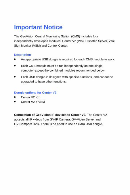
Important Notice The GeoVision Central Monitoring Station (CMS) includes four independently developed modules: Center V2 (Pro), Dispatch Server, Vital Sign Monitor (VSM) and Control Center. Description • An appropriate USB dongle is required for each CMS module to work.
• Each CMS module must be run independently on one single computer except the combined modules recommended below.
• Each USB dongle is designed with specific functions, and cannot be upgraded to have other functions.
Dongle options for Center V2 • Center V2 Pro • Center V2 + VSM
Connection of GeoVision IP devices to Center V2. The Center V2 accepts all IP videos from GV-IP Camera, GV-Video Server and GV-Compact DVR. There is no need to use an extra USB dongle.

Dongle options for Dispatch Server • Dispatch Server • Dispatch Server + VSM
Dongle options for VSM • VSM • VSM + Control Center • VSM + Center V2 • VSM + Dispatch Server
Dongle options for Control Center • Control Center or IP Matrix • Control Center + Advanced Video Analysis • Control Center + VSM • Control Center + VSM + Advanced Video Analysis Connection of IP devices to Control Center. The Control Center accepts IP videos from both GeoVision and third-party IP video devices and there is no limitation on the number of channels. There is no need to use an extra USB dongle.
2
Important Notice
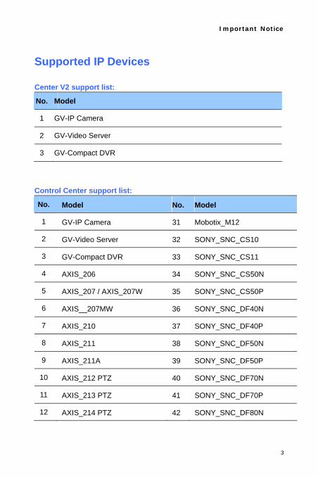
Supported IP Devices Center V2 support list:
No. Model
1 GV-IP Camera
2 GV-Video Server
3 GV-Compact DVR
Control Center support list:
No. Model No. Model
1 GV-IP Camera 31 Mobotix_M12
2 GV-Video Server 32 SONY_SNC_CS10
3 GV-Compact DVR 33 SONY_SNC_CS11
4 AXIS_206 34 SONY_SNC_CS50N
5 AXIS_207 / AXIS_207W 35 SONY_SNC_CS50P
6 AXIS__207MW 36 SONY_SNC_DF40N
7 AXIS_210 37 SONY_SNC_DF40P
8 AXIS_211 38 SONY_SNC_DF50N
9 AXIS_211A 39 SONY_SNC_DF50P
10 AXIS_212 PTZ 40 SONY_SNC_DF70N
11 AXIS_213 PTZ 41 SONY_SNC_DF70P
12 AXIS_214 PTZ 42 SONY_SNC_DF80N
3

4
13 AXIS_216FD / AXIS_216FD-V
43 SONY_SNC_DF80P
14 AXIS_221 44 SONY_SNC_P1
15 AXIS_223M 45 SONY_SNC_P5
16 AXIS_225FD 46 SONY_SNC_RX550N
17 AXIS_231D+ 47 SONY_SNC_RX550P
18 AXIS_232D+ 48 SONY_SNC_RZ25N
19 AXIS_233D 49 SONY_SNC_RZ25P
20 IQEye_301 50 SONY_SNC_RZ50N
21 IQEye_302 51 SONY_SNC_RZ50P
22 IQEye_510 52 Panasonic_BB_HCM110
23 IQEye_511 53 Panasonic_BB_HCM311
24 IQEye_701 54 Panasonic_BB_HCM331
25 IQEye_702 55 Panasonic_BB_HCM371
26 JVC_VN-C20U 56 Panasonic_BB_HCM381
27 JVC_VN-C205U 57 Panasonic_BB_HCM403
28 JVC_VN-C215U 58 Panasonic_BB_HCE481A
29 JVC_VN-C625U 59 Panasonic_BL-C10
30 JVC_VN-C655U 60 Panasonic_BL-C30
The product specifications are subject to change without notice.

Chapter 1 Center V2 With Center V2, central monitoring station (CMS) can be deployed immediately because it brings multiple GV-Systems together into an integrated interface, allowing the operator to manage several systems from one point of control. The basic feature of Center V2 is to view live video, and receive video evidence (in an attachment format) when any alerts are sent to Center V2. This helps the remote-end operator easily determine the nature of the alarm.
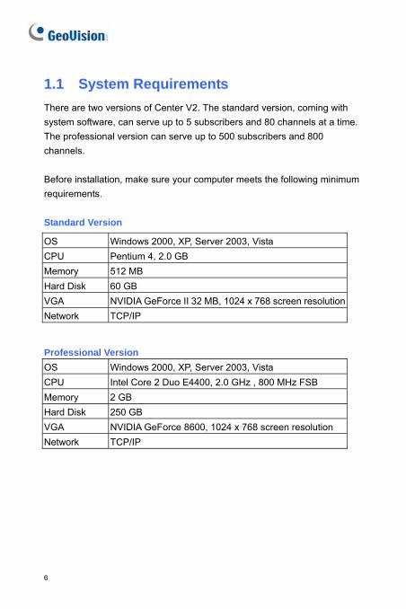
1.1 System Requirements There are two versions of Center V2. The standard version, coming with system software, can serve up to 5 subscribers and 80 channels at a time. The professional version can serve up to 500 subscribers and 800 channels. Before installation, make sure your computer meets the following minimum requirements. Standard Version
OS Windows 2000, XP, Server 2003, Vista CPU Pentium 4, 2.0 GB Memory 512 MB Hard Disk 60 GB VGA NVIDIA GeForce II 32 MB, 1024 x 768 screen resolutionNetwork TCP/IP
Professional Version OS Windows 2000, XP, Server 2003, Vista CPU Intel Core 2 Duo E4400, 2.0 GHz , 800 MHz FSB Memory 2 GB Hard Disk 250 GB VGA NVIDIA GeForce 8600, 1024 x 768 screen resolution Network TCP/IP
6

Center V2 1
1.2 Installing Center V2
1. Insert the CMS Software CD to your computer. It will automatically run and a window appears.
2. Select the Install V 8.2.0.0 Central Monitoring System item.
3. Click CenterV2 System, and follow the on-screen instructions.
Note: The Center V2 Pro application is provided with a USB dongle. Make sure the dongle is tightly attached to your computer.
7

1.3 The Center V2 Window
17
16
17
1820 21
22
23
2
3
4
5
6
7
1210
1113
1415
9
8
1
19
Figure 1-1
The controls on the Center V2 window:
No. Name Description
1 Monitoring Window
Displays live video.
2 Status Panel Indicates the date, time, remaining disk space, and the total number of online channels versus available channels.
3 Find A Subscriber
Type the desired ID in the Current Subscriber field and click this button to search.
8

Center V2 1
4 Subscriber List Displays subscribers’ ID names and online status. Blue Icon: Indicates the subscriber is online. White Icon: Indicates the subscriber is off-line. Alarm Icon: Indicates either motion has been detected or the I/O has been triggered at the subscriber’s site.
5 Event List Accesses Event Log and Event List. 6 SMS Configures the SMS service. 7 I/O Device Configures and forces output devices at Center V2. 8 Screen Division In the 1024 x 768 resolution, select 6, 15, or 24
screen divisions for a single monitor; 9, 25, or 36 screen divisions for dual monitors. In the 1280 x 1024 resolution, select 6, 12, or 24 screen divisions for a single monitor; 9, 20, or 42 screen divisions for dual monitors. In the 1600 x 1200 resolution, select 6, 12, or 24 screen divisions for a single monitor; 9, 16, or 36 screen divisions for dual monitors. In the 1680 x 1050 resolution, select 6, 15, or 28 screen divisions for a single monitor; 9, 20, or 42 screen divisions for dual monitors. In the 1920 x 1200 resolution, select 6, 15, or 28 screen divisions for a single monitor; 9, 20, or 42 screen divisions for dual monitors. In the 1920 x 1080 resolution, select 6, 15, or 28 screen divisions for a single monitor; 6, 20, or 35 screen divisions for dual monitors. For resolution, see Layout Settings later in this chapter.
9 Host Info Displays the connection status of subscribers. 10 Preference
Settings Brings up these options: System Configure, Password Setup, E-mail Setup, Notification, Customize Alarm Report and Automatic Failover Support.
9

11 Exit Closes or minimizes the Center V2 window. 12 Accounts Adds, deletes or modifies subscriber accounts. 13 Refresh
Channel Refreshes the connection status.
14 Next Page Displays the next page of camera views. 15 Previous Page Displays the previous page of camera views. 16 Flag Flags an event for later reference. 17 Clipboard Displays the Alarm Report dialog box. 18 Clip Indicates an event coming with an attachment.
Double-click the event to open the attached video file. 19 ID Indicates a subscriber’s ID. 20 Event Type Indicates the event type: Alarm, Attachment,
Connection, Login/Logout, Motion, System, and Trigger.
21 Message Indicates associated information for each event type.
22 Message Time Indicates when Center V2 receives an event.
23 Start Time Indicates when an event happens at the subscriber’s site.
10

Center V2 1
A list of Types and Messages will be displayed on Center V2:
Type Message Motion Camera xx detected motion. Trigger Module xx triggered. Connection Camera xx video lost; Module xx I/O lost; Network abnormal;
Fail to login to dispatch server; Dispatch server is shutdown; Video signal of xx has resumed; Module xx has returned to normal; Failed to login SMS server; Failed to send short message; SMS server is shutdown.
Alarm Disk Full; Restarted Failed; Multicam Closed; There isn’t enough space for recording; Multicam Surveillance System has been closed; An unexpected error occurred in Multicam Surveillance System. (Error Code: 1 or 2); There is an intruder; Object Missing; Unattended Object; Alert Message of POS; Scene Change.
System Start/end service; IP change; Record failed; Status change of monitoring camera. On: xx Off: xx / (By Schedule); Stop/start all cameras monitoring; Start/stop I/O Monitoring. / (By Schedule); Schedule start; Schedule stop. All monitoring devise are stop too. Start monitoring all type events; Stop monitoring all type events; Subscriber session is not established. Wait-time expired; Unexpected logout before subscriber session is completed; Can’t find USB Protection Key.
Attachment Record file of Camera xx.
Note: Error Code 1 indicates a codec error; Error Code 2 indicates that users can’t write or record any data due to HD failure or user privilege.
11

1.4 Creating a Subscriber Account
Create at least one subscriber before starting Center V2 services. On the Center V2 window, click the Accounts button (No. 12, Figure 1-1). The Address Book window appears.
1 2 3 4 5 6 7 8
Figure 1-2
The buttons on the Address Book:
No. Name Description 1 Add A Group Adds a group. 2 Add A Subscriber Adds a subscriber 3 View/Edit Subscriber
Address Book Highlight one subscriber and click this button to open Subscriber Address Book for viewing and editing.
4 Delete A Group/Subscriber
Highlight a group or a subscriber and click this button to delete it.
5 Find A Subscriber Searches a subscriber account.
6 Import / Export Address Book
Imports or exports the address book data.
7 Subscriber Settings Highlight one subscriber and click this button to configure the settings of video and alert formats.
8 Subscriber Schedule Sets up subscription schedules.
12

Center V2 1
Creating a Subscriber 1. Click the Add A Group button (No. 1, Figure 1-2) to create a group.
2. Click the Add A Subscriber button (No. 2, Figure 1-2). The Subscriber Address Book dialog box appears.
Figure 1-3
3. Enter a Login ID and Password (required). Those will be the ID and Password for the subscriber to log in to the Center V2.
4. Enter the subscriber’s contact information in the rest of fields (optional).
13

If you wish to send e-mail alerts to this subscriber, type its e-mail address. For e-mail settings, see E-Mail Alerts later in this chapter.
If you wish to send SMS alerts to this subscriber, type its country code and mobile number. For SMS Server settings, see SMS Alerts later in this chapter.
5. Click OK to save the above settings. This dialog box appears.
Figure 1-4
6. The options in the dialog box are discussed below. You may accept the default settings here, and edit them later by clicking the Subscriber Settings button (No. 6, Figure 1-2) on the toolbar. When you click OK, the subscriber account then is created.
Subscriber Settings [Monitor Option]
Image Size: Sets the video size from the subscriber. The following chart shows how the image size set at the subscriber corresponds to different settings at Center V2. For example, if Center V2 wants to receive 720 X 240 image, the subscriber must set the video resolution to 720 x 480 or 720 x 240.
14

Center V2 1
Subscriber
Center V2 320 x 240 360 x 240 360 x 288 640 x 240 640 x 480 720 x 240 720 x 480 720 x 576
Normal 320 x 240 360 x 240 360 x 288 320 x 240 320 x 240 360 x 240 360 x 240 360 x 288
Middle 320 x 240 360 x 240 360 x 288 640 x 240 640 x 240 720 x 240 720 x 240 720 x 288
Large 320 x 240 360 x 240 360 x 288 640 x 240 640 x 480 720 x 240 720 x 480 720 x 576
Center V2 supports mega pixel resolution. If the subscriber sets the resolution to mega pixel and the Center V2 operator wishes to view the videos of the same size, the Center V2 operator can select Actual Size. Note this setting will require a lot of bandwidth. Auto Record Video: Center V2 automatically records events based
on the following Record Mode.
[Record Mode] Live Mode: Streams live video to Center V2. Make sure you have
enough bandwidth to receive video in live. To set the maximum time of a video clip to be sent to Center V2, click the Settings button. The more the set minutes, the bigger the file size; and therefore more time is required to send the file over Internet.
Attachment Mode: A defined time of event will be recorded before sending to Center V2. The attachment will be sent out immediately once your subscriber is connected to Center V2. The Attachment Mode also provides several options associated with the attachment. Click the Settings… button to bring up this Record Settings – Attachment Mode dialog box. See Attachment Mode Settings below for further setup.
Both (Live & Attachment): Sends both live video and attachment file.
[Color of Channel Caption] Changes the color of channel headings. For further setup, see Changing the Color of Channel Heading later in this chapter.
15

Attachment Mode Settings
In the Subscriber Settings dialog box (see Figure 1-4), select Attachment Mode, and click the Settings… button beside. This dialog box appears.
Figure 1-5
[Record Options (per camera)] Pre-Rec Total Frames: Determines the total pre-recorded frames in
a video attachment. Pre-Rec Frames/sec Limitation: Determines the frame rate in the
pre-recorded period. Note: Dividing the Pre-Rec Total Frames by Pre-Rec Frames/Sec Limitation, you will get the total time of the video attachment. Motion Frames/sec Limitation: Determines the frame rate of the
video to be sent as an attachment. Recording Quality: Use the slider bar to adjust the video quality in
3 levels.
16

Center V2 1
[Attachment option (Record by Motion)] Defines the duration of the video attachment delivered upon motion. Max video Clip: Determines the duration of the video attachment. Pos-Rec Motion: Determines how many more seconds of video to
be sent when motion stops. Alerts interval: Determines the interval between sent motion
events. [Attachment option (Record by I/O trigger)] Defines the duration of the video attachment delivered upon I/O trigger.
Changing the Color of Channel Heading For easy identification, the channel headings can be as colorful as you wish. In addition to the change of color and font of the channel headings, its background color can be customized as well. 1. On Center V2 window, click the Accounts button (No.12, Figure 1-1),
highlight a subscriber, and click the Subscriber Setting button on the toolbar. The Subscriber Settings dialog box (see Figure 1-4) appears.
2. Click the Color of Channel Caption button. This dialog box appears.
Figure 1-6
17

3. Set a color you wish to use, and click OK. The Color of Channel Caption button now displays the color you selected.
4. On the Center V2 window, click the Preference Setting button (No. 10, Figure 1-1) and select System Configure. The Preference dialog box (see Figure 1-11) appears.
5. Click the General tab, and check the Use the subscriber setting color as background option. Now the background color of the channel heading will be in the color you selected.
Channel Heading
Figure 1-7
18

Center V2 1
1.5 Creating a Subscriber Schedule
The Center V2 operator can create schedules to monitor subscription status. When subscribers don’t log in Center V2 on the programmed time, the operator and subscribers will get notified.
• When a subscriber doesn’t log in Center V2 on time, this message will appear on the Event List: Subscriber session is not established. Wait-Time expired. When a subscriber logs out suddenly during a service time, this message will appear: Unexpected logout before subscriber session is completed.
• To activate the computer and output alarm to notify the operator while a SMS and E-mail message being sent out to a subscriber, use the Notification feature. For details, see Notification Settings later in this chapter.
Setting Up a Schedule 1. On the Center V2 window, click the Accounts button (No. 12, Figure
1-1) to display the Address Book window. 2. Highlight one subscriber, and click the Subscriber Schedule (No. 7,
Figure 1-2) to display the Schedule window.
Figure 1-8
19

3. On the Schedule window menu, click Schedule, select Setup Wizard and follow the Wizard instructions.
4. When the following dialog box appears during the instructions, drag the mouse over the Login timeline to define the Start and End time.
1 2 53 4
6
7
Figure 1-9 The controls on the Setup Wizard:
No. Name Description 1 Include Displays task time. 2 Exclude Displays non-task time. 3 Add Draws task time. 4 Erase Erase task time. 5 Timeline Defines the time periods. 6 Login Displays the Login timeline. 7 Notification Displays the E-mail and SMS timelines.
5. Click Next when you finish the schedule. The Setup Wizard dialog boxes pops up again, and then click Finish to exit.
20

Center V2 1
Scheduling Alert Notification Both e-mail and SMS notifications can be scheduled ahead. E-mails and SMS messages will be sent out within the scheduled period of time.
1. On the Schedule window, double-click an established plan. This Plan dialog box appears.
Figure 1-10 2. On this Plan window, click the Advanced Setting button . The
Advanced Setting dialog box appears. 3. Expand the Notification folder, and check or uncheck the alert
methods to be scheduled. 4. On the Plan dialog box, click the Notification button, drag the mouse
over SMS and / or E-mail timelines to define the Start time and End time to send out alerts.
Note: Once you enable the schedule function, you will not be notified when events occur outside the scheduled period of time.
21

1.6 Configuring Center V2
On the Center V2 window, click the Preference Settings button (No. 10, Figure 1-1), and select System Configure to display the following Preference window. This window contains these tabs: (1) General, (2) Layout, (3) Network, (4) Record and (5) Dispatch Server.
[General]
Figure 1-11
22

Center V2 1
[Monitor Option] Manual close channel: Closes the triggered camera view
manually. Close the camera view when motion stopped: Closes the
triggered camera view automatically when motion stops. Post Motion: Specifies the duration of the camera view remaining
on the monitoring window after motion stops. Camera send by I/O trigger will monitor: Specifies the duration of
the camera view remaining on the monitoring window when an I/O device is triggered. To keep the camera view remaining on the monitoring window even after the alarm is finished, click the right-arrow button, and uncheck Latch Trigger. Then the camera view will keep remaining on the monitoring window for the specified time. For example, the alarm is triggered for 5 minutes and you set 10 minutes, which means the total display time will be 15 minutes.
Camera send by Wiegand capture device will monitor: Specifies the duration of the camera view remaining on the monitoring window when the access control system, connected to GV-Video Server, is triggered. For details, see Chapter 8 CMS Configurations in the GV-Video Server User’s Manual.
Image Quality: Adjusts the video quality. Moving the slide bar to the right side for the better quality and the bigger image size.
Enable Directdraw: Enables an enhanced image performance for live video.
[Start-up] Auto Run when Windows Starts: Automatically runs Center V2
when Windows starts. Login SMS Server when Start Service: Automatically logs in SMS
Server when Center V2 starts. You will be prompted to enter the IP address, Port, ID and Password of the SMS server.
23

[Channel Caption] Font and Color: Click the Settings…. button to change the font
and color of the captions. Use the subscriber setting color as background: Checks the
option to apply the caption settings. For details, see Changing the Color of Channel Heading earlier in this chapter.
[Layout] This feature transfers the Event List window to a separate computer while the monitoring windows are displayed in the current computer. For the application, your VGA card needs to support Twin View, and your Windows desktop must be properly set up for the display across two computer monitors.
Figure 1-12
24

Center V2 1
Screen Resolution: Detects the current screen resolution on your PC.
Main Panel Resolution: Sets the Center V2 panel resolution to 1024 x768, 1280 x1024, 1600 x 1200, 1680 x 1050, 1920 x 1200 or 1920 x 1080. This feature is only available when your PC screen resolution is higher than 1280 x 1024. The new resolution is effective after next login.
Floating Event List: Moves the Event List window to a separate monitor at the bottom or right side.
[Network]
Figure 1-13
25

Location Name: Indicates the name of the PC where Center V2 is installed.
Assign IP: When your router or system has more than one IP address, you can assign an IP address for the communication between DVR and Center V2.
Enhance Network Security: Applies enhanced security for Internet. When the feature is enabled, all subscribers using earlier version than version 7.0 cannot access the Center V2 anymore.
Center Port: Indicates the communication port used by the Center V2. To automatically configure the port on your router by UPnP technology, click the Arrow button. For details, see UPnP Settings, Chapter 6 in the User’s Manual.
Accept the Connection of Video Server: Enables the connection to the GV-Video Server. The default port is 5551, or you can modify it to match the Center V2 port on the GV-Video Server. For details, see GV-Video Server User’s Manual.
26

Center V2 1
[Record]
The feature allows you to assign a path to store video files. Click the Add New Path button to assign a path; click the [X] button to delete a path. If the Recycle item is checked, the system will delete old files when storage space falls short of 800MB; if not checked, Center V2 will stop recording when storage space falls short of 800MB.
Figure 1-14
Note: Every time when the Recycle function is activated, the files of 400MB will be deleted.
[Dispatch Server] See 2.8 Connecting Center V2 to Dispatch Server.
27

1.7 Connecting to Center V2
A single DVR can connect up to two Center V2 centers simultaneously for central monitoring. To configure GV-System in order to access Center V2 remotely through a network connection, follow these steps:
1. In the Main System, click the Network button, and select Connect to Center V2. This dialog box appears.
Figure 1-15
2. Type the IP address, ID and password of the first Center V2. Modify the default port if necessary. Click OK. This dialog box appears.
Figure 1-16
28

Center V2 1
3. If you want to establish the connection to the other Center V2, click the created Center V2 IP, select Add Center V2 and then type the login infomation.
4. When you finish the settings, in the Connect to Center V2 dialog box (see Figure 1-16), click the Connect button to start. When the connection is established, Center V2 will start receiving video or attachments from the subscriber.
29

Normal Mode Setup
To further define the communication conditions between the subscriber and Center V2, select Normal Mode on the Connect to Center V2 dialog box (Figure 1-16), and then click the Conigure button for setup. A menu includes two options of General Settings and Advance Settings. The Advance Settings dialog box includes these tabs: (1) Camera, (2) Other and (3) I/O Device.
General Settings The settings define the retry modes and communication ports between GV-System and Center V2.
Figure 1-17
30

Center V2 1
[Connection Broken]
Maximum Retries: Sets the number of retries if connection is not immediately available.
Retry Interval: Sets the interval between retries. Retry until connected: Keeps GV-System on trying until connected
to Center V2. Retry in the background: Hides the retries in the background.
[Codec] Selects Geo Mpeg 4 (default), Geo Mpeg 4 (ASP) or Geo H264 as the compression method for video sent to Center V2. [Connective Port] Displays ports used for communication. It is recommended to keep the default settings, unless otherwise necessary. The Center Port must match the Center Port assigned in Center V2; see Figure 1-13. To automatically configure these ports on your router by UPnP technology, click the Arrow button. For details, see UPnP Settings, Chapter 6, User’s Manual on the Surveillance System Software CD. [Temp Folder] Attachments are temporarily stored in this folder while waiting to be sent to Center V2. In case the connection is broken, attachments meant to be sent to Center V2 could be found here. Once the connection is back to normal, events saved in the Temp Folder will be sent out immediately.
31

Advanced Settings
[Camera] The settings define which camera condition to notify Center V2. To configure the event type, first disable the Monitoring all type events option in Figure 1-16.
Figure 1-18 The Arrow buttons: Click the left or right arrow button to select the
camera to be configured. Or you can click the Finger button to apply the settings to all cameras.
Send to Center V2 when Motion is Detected: Sends video to Center V2 when motion is detected. Click the Set Camera(s) button to assign cameras for the application. Event Type: If the subscriber wants Center V2 always to get notified of motion detection, select Emergency. If the subscriber wants Center V2 to get notified of motion detection only when an assigned input is triggered, select Normal.
32

Center V2 1
Allow Center V2 to View Live Camera: Gives Center V2 the privilege to view your cameras at any time. Click the Set Camera(s) button to assign cameras for the application.
Allow Center V2 to Control PTZ Camera: Gives Center V2 the privilege to control your PTZ cameras. Remember to properly set up camera mapping first. See Mapping PTZ Cameras, Chapter 1, User’s Manual on the Surveillance System Software CD.
Notify Center V2 when the following events come up: Notifies Center V2 when any of these alert events occur: Intruder, Missing Object, Unattended Object and Scene Change.
Event Type: If the subscriber wants Center V2 always to get notified of these alert events, select Emergency. If the subscriber wants Center V2 to get notified of these alert events only when an assigned input is triggered, select Normal.
Note: To set an input trigger for the notification of Normal events, see Security Service, [I/O Device] later in this chapter.
33

[Other] Define other communication conditions between GV-System and Center V2.
Figure 1-19
[Audio] Applies any of these options here may generate privacy issues. Think before you make any selection. Allow Audio-Out to CenterV2: Allows Center V2 to listen to the
audio from GV-System. Accept Audio-In from CenterV2: Allows Center V2 to use the
talkback feature when emergency occurs.
34

Center V2 1
[Other] Allow Center V2 to Get System Information: Allows Center V2 to
get system information on your GV-System. Send Alert Message of POS’s Loss Prevention to Center V2:
Notifies Center V2 about the events of POS Loss Prevention. Time synchronization with Center V2: Enables the time
increment/decrement of minutes and seconds at the subscriber site to match the time at the Center V2.
Notify Center V2 when the storage space was full: Notifies the Center V2 when the subscriber’s storage space is insufficient.
35

[I/O Device] The settings define which I/O condition to notify Center V2. To configure these settings, first disable the Monitoring all type events option in Figure 1-16.
Figure 1-20
[I/O Device] Notifies the Center V2 of when I/O devices are triggered. Use the Arrow buttons to configure each I/O device, or click the Finger button to apply to all I/O devices.
Allow Center V2 to Enable / Disable I/O: Allows Center V2 manually arm/disarm any I/O devices at the subscriber’s site without interrupting the monitoring. For example, when an alarm is triggered at the subscriber site, the Center V2 can turn it off remotely before arriving at the site. Meanwhile, GV-System still remains on monitoring.
Send to Center V2 when I/O is Triggered: Notifies Center V2
36

Center V2 1
when any selected input is triggered.
With Camera(s): Sends the camera video to Center V2 when the selected input is triggered. Click the Set Camera(s) button to assign cameras for the application.
Event Type: If the subscriber wants Center V2 always to get notified of the input trigger, select Emergency. If the subscriber wants Center V2 to get notified of the input trigger only when an assigned input is triggered, select Normal. Right Arrow button: Sets the delay time to notify Center V2 of input trigger. This feature is only available when the Normal type is chosen.
Exit Delay: While the system is activated, this feature provides an interval of time for the subscriber to exit the premises. During this time, the specified input (e.g. an exit/entry door) is inactive. Once the exit delay expires, the input will be fully armed.
Entry Delay: While the system is activated, this feature provides an interval of time for the subscriber to entry the premises. During this time, the specified input (e.g. an exit/entry door) is inactive so that the subscriber can disarm the system. If the subscriber fails to do, once the entry delay expires, Center V2 will get notified of the input trigger.
Output Module: Enables the assigned output module when the selected input module is triggered. For this example, when the I/O Device (Module 1, Input 4) is triggered, the Output (Module 1, Pin 3) will be activated simultaneously. Right Arrow button: Sets the delay time to trigger the assigned output module. Event Type: If the subscriber wants Center V2 always to get notified of the output trigger, select Emergency. If the subscriber wants Center V2 to get notified of the output trigger only when an assigned input is triggered, select Normal.
37

Note: 1. To set an input trigger for the notification of Normal events, see
[Security Service] below. 2. The delay settings in Send to Center V2 when I/O is triggered and
Output Module allow you to enter your premises and disable input/output module before it is activated. To disable prior I/O settings, the subscriber may exit the connection to Center V2 or use the Stop monitoring normal events when selected pin is triggered feature in Figure 1-20.
Allow Center V2 to Force Output: Allows Center V2 to manually force output devices installed at the subscriber’s site.
[Security Service] Supports two types of access control systems: Momentary and Maintained Mode.
Momentary Mode: Pushbutton switches that are normally open and stay closed only as long as the button is pressed. Momentary switches allow turn-on or turn-off from multiple locations.
For example, certain premises have a designated entry/exit door. When the staff enters the entry door, the system starts monitoring. When the staff leaves from the exit door, the system stops monitoring.
Maintained Mode: Push-on/push off button switches that stay open until thrown, and then stay closed until thrown again. Maintained switches are convenient for only one switch location.
For example, in the business hour when the door is opened, the system stops monitoring; in the non-business hour when the door is closed, the system starts monitoring.
38

Center V2 1
Panic Button Setup You may set up a panic alarm button at your GV-System. In case of emergency, press the button immediately to send the associated video to Center V2. To set up a panic alarm, select Panic Button in the Connect to Center V2 dialog box (see Figure 1-16), click the Configure button and select Advance Settings. This dialog box appears.
Figure 1-21
[Panic Button] Assigns an input device to be the panic alarm button. Trigger by I/O: Assigns an input module and a pin number. Output Module: Enables an assigned output module when the
panic button is pressed. For this example, when the panic button (Module 1, Pin 1) is pressed, the output module (Module 3, Pin 4) will be triggered simultaneously.
[Send which Camera(s) to Center V2] Select which camera video should be sent to Center V2 when the panic alarm button is pressed. [Connective Port] The communication ports used by Center V2. It is recommended to keep all defaults, unless otherwise necessary.
39

Detecting Input Status The feature is designed to monitor all inputs for a change of state whenever the subscriber starts the Center V2 monitoring. A change from the previously defined state (N/O to N/C or N/C to N/O) will activate an alarm condition.
Click on the Connect to Center V2 dialog box (see Figure 1-16). For details, see Detecting Input Status, Chapter 2, User’s Manual on the Surveillance System Software CD.
40

Center V2 1
1.8 Event Log Browser
The Event Log Browser allows you to locate a desired event coming from subscribers. On the Center V2 window, click the Event List button (No. 5, Figure 1-1) and select View Event Log to display the following window. Tip: You can quickly access the Event Log of a specific subscriber, instead of filtering all events. Right-click one subscriber on the Subscriber list (No. 4, Figure 1-1), select Event Log and then click a desired log type.
1 2 3 4 5 6 7 8 9
Figure 1-22
The buttons on the Event Log Browser:
No. Name Description
1 Open Opens an event log.
2 Reload Refreshes the event log manually
3 Start/Stop Synchronous EventLog
Refreshes the event log automatically.
4 Filter Defines the search criteria.
5 Refresh the Filter Result Refreshes the filter result.
6 Backup Exports the current event list and video files.
41

7 Page Setup Creates header and footer on the printout of Event Log.
8 Print Prints the current event list.
9 Exit Exits the browser.
Opening the Event Log Click the Open button (No. 1, Figure 1-22) to launch the following Open DataBase dialog box. Define a time period, select the type of log, and click OK for search. Events matching the search criteria will be loaded to the Event Log Browser window.
Figure 1-23
42

Center V2 1
Filtering the Event Log Click the Filter button (No. 4, Figure 1-22) to bring up the following Event Log -- Filter window. This option allows you to perform a search based on criteria.
Figure 1-24
Filters Read: Searches the events read in Center V2. Clipboard: Searches the events with alarm reports. Flag: Searches the events flagged important. Clip: Searches the events containing video attachments. ID: Searches the events from a specific subscriber. Type: Searches the events based on the nature of events. Message: Searches the events by keywords. Message Time: Searches the events by the arriving time or date to
Center V2. Start Time: Searches by the starting time of the events occurred at
the subscriber site.
43

Applying Multiple Filters This option allows you to define several filter commands for search. Click the Add New Command button to add a new filter command. When you click OK, all events matching the defined commands will be listed on the Event Log Browser.
Removing Filters
Select the filter command you wish to remove from the filter list, and then click the Remove Selected Command button to remove it.
Event Log Settings On the Center V2 window, click the Event List button (No. 5, Figure 1-1), and select Event Log Setting to display the following dialog box:
Figure 1-25 [Event List] Auto Import: Specify the number of days to be loaded when Event
Log Browser is launched.
44

Center V2 1
[Event Log] Keep Days: Enter the number of days to keep log files. Recycle: Delete the files of the oldest day when storage space is
lower than 500MB. Log Path: Click the [...] button to assign a storage path.
Print Setup You can create the Footer and Header on the printout of Event Log. 1. On the Event Log Browser, click the Page Setup button (No. 7, Figure
1-22) to display this dialog box.
2. Check the items and type the information you want to print out.
3. Click OK to apply the settings.
Printout
Creator
User-defined text
Print time and date
Figure 1-26
4. Click the Print button (No.8, Figure 1-22) to start.
Note: To print out the alarm reports, see Printing Alarm Reports later in thic chapter.
45

1.9 Backing Up to CD/DVD Other than backing up log data to a local drive, you can export log data to CD or DVD.
1. In the Event List Browser window, click the Backup button (No.6, Figure 1-22). This dialog box appears.
Figure 1-27
2. Select Temp folder, and use the […] button to assign a path for temporary storage of backup data. Check the options of backup file types. Click OK.
3. After the backup files are saved in the temp folder, a backup information dialog box will be prompted for you to confirm.
4. Click OK. This dialog box appears.
46

Center V2 1
Figure 1-28
Using CD/DVD: Click to back up files to the CD or DVD using the third-party software. Click the […] button to assign the desired burning software (.exe file).
CD Using OS-Burning: This option is only available when you use Windows XP, Server 2003 or Vista. It burns files to the CD or DVD using the inbuilt software of the operating system.
5. Click OK to start.
47

1.10 Monitoring and Managing Subscribers This section describes how to monitor and manage subscribers in these parts: (1) Showing I/O Status, (2) I/O Activation (3) Camera/Audio Control, (4) Camera Monitor (5) Viewing Subscriber Information (6) Subscription Service Options.
Showing I/O Status You can view the status of input devices at the subscriber’s site, as well as forcing the outputs. On the Subscriber List (No. 4, Figure 1-1), right-click one online subscriber, and then select Show I/O status to display this window.
Figure 1-29
48
Center V2 1
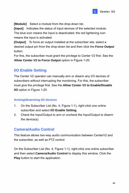
[Module] Select a module from the drop-down list. [Input] Indicates the status of input devices of the selected module. The blue icon means the input is deactivated; the red lightening icon means the input is activated. [Output] To force an output installed at the subscriber site, select a desired output pin from the drop-down list and then click the Force Output button. For this, the subscriber must grant the privilege to Center V2 first. See the Allow Center V2 to Force Output option in Figure 1-20.
I/O Enable Setting The Center V2 operator can manually arm or disarm any I/O devices of subscribers without interrupting the monitoring. For this, the subscriber must give the privilege first. See the Allow Center V2 to Enable/Disable I/O option in Figure 1-20.
Arming/disarming I/O devices
1. On the Subscriber List (No. 4, Figure 1-1), right-click one online subscriber and select I/O Enable Setting.
2. Check the Input/Output to arm or uncheck the Input/Output to disarm the device(s).
Camera/Audio Control This feature allows two-way audio communication between CenterV2 and the subscriber, as well as PTZ control. On the Subscriber List (No. 4, Figure 1-1), right-click one online subscriber and then select Camera/Audio Control to display this window. Click the Play button to start the application.
49

1 2 3 4 5 6 7
Figure 1-30
The controls on the Camera/Audio Control:
No. Name Description
1 Close Closes the Control window.
2 Play Plays live video.
3 Stop Stops playing video.
4 Microphone Enables speaking to the subscriber. The subscriber must grant the privilege first. See the Allow Audio-Out to Center V2 option in Figure 1-19.
5 Speaker Enables live audio from the subscriber. The subscriber must grant the privilege first. See the Accept Audio-In from Center V2 option in Figure 1-19.
6 Change Camera Switches camera channels.
7 PTZ Control Includes PTZ Control Panel and the PTZ Automation function.
50

Center V2 1
Camera Monitor Use the Camera Monitor window to define the following: • Enable and disable live display
(The subscriber must give the privilege first. See the Allow Center V2 to View Live Camera option in Figure 1-18)
• Define the interval between incoming events triggered by motion detection and video lost
1. On the Subscriber List (No. 4, Figure 1-1), right-click one online
subscriber and select Camera Monitor. 2. The Camera Monitor window appears.
Figure 1-31
51

Live drop-down list: Highlight one camera, and select Play (enable live display) or Stop (disable live video).
Suspended Motion Monitoring: Highlight one camera, and set the interval between incoming events triggered by motion detection. Alternatively, you can right-click one live camera channel on the monitoring window and select Suspend for the same setting.
Suspend Video Lost Monitoring: Highlight one camera, and set the interval between incoming events triggered by video lost.
Status column: Displays the status of video lost from cameras or disconnection.
3. Click OK to apply the settings. If the camera is enabled for live display, you will see in the upper right corner of its monitoring window; otherwise, you will see .
52

Center V2 1
Viewing Subscriber Information To view the general information about your subscribers, click the Host Information button (No. 9, Figure 1-1) on the Center V2 window to display the Host Information window. Choose a subscriber from the list, and click the View Information… button to view its related information.
Figure 1-32
Subscription Control The Center V2 operator can disable its services to an individual subscriber when subscription expires. On the Address Book (Figure 1-2), right-click one subscriber and select Disable. To restore the subscription, right-click that subscriber again and select Enable.
53

1.11 Instant Recording and Playback You can enable live view in a more convenient way, and start and stop recording instantly to any live-view camera.
Enabling Live View You can enable live view of any camera by right-clicking it in the
subscriber’s list, and then selecting Live View.
Figure 1-33
When a subscriber is in focus, you can enable live view to all its cameras. Click a subscriber in the list and select Focus on this subscriber only. When the subscriber is in focus, click the subscriber again and then select View All Cameras (Live). All cameras of this focused subscriber display live view.
Figure 1-34
54

Center V2 1
Recording and Playing Back Instantly When a camera is enabled for live view, you can start and stop
recording by clicking the button on the channel heading. As soon as you stop recording, you can double-click the attachment of
the event in the Event List for instant playback.
55

1.12 Output Alerts When alert conditions occur, you can activate the output devices installed either at the Center V2 site or at the subscriber site.
Forcing Outputs of Center V2 To configure output devices at the Center V2 site, click the I/O Device button (No. 7, Figure 1-1) on the Center V2 window and then select GVIO, GVIO-USB(4) or GVIO-USB (16) from the menu. Currently the application only supports GV-IO modules. For setup details, see Setting Up I/O Devices, Chapter 2, User’s Manual on the Surveillance System Software CD. To automatically force outputs when alert conditions occur, see Notification Settings later in this chapter. To manually force outputs, click the I/O Device button (No. 7, Figure 1-1) on the Center V2 window, and then select Force Output to display the Force Output of Local I/O Device window. Select a desired module and then click Finger buttons to activate outputs.
Forcing Outputs of a Subscriber See Showing I/O Status earlier in this chapter.
56

Center V2 1
1.13 Notification Settings Center V2 can automatically activate the assigned computer and output alarm to notify the operator while a SMS and an e-mail message are being sent out to subscribers, when alert conditions occur. For this application, click the Preference Settings button (No. 10, Figure 1-1) on the Center V2 window and select Notification to display this window.
Figure 1-35
[List box] Select an alert condition for configuration. The alert conditions include: (1) Video Lost, (2) I/O Module Lost, (3) I/O Trigger (Normal), (4) Trigger (Emergency), (5) Connection Lost, (6) Subscriber Login, (7) Subscriber Logout, (8) Camera Motion, (9) Surveillance System Abnormality, (10) Intruder, (11) Missing Object, (12) Unattended Object, (13) Scene Change, (14) POS Loss Prevention, (15) Disk Full, (16) Stop all camera monitoring, (17) Stop I/O Monitoring, (18) Start Monitoring All Type Events, (19) Stop Monitoring All Type Events, (20) Wait-Time Expired and (21) Unexpected Logout.
57
[Alert Approach] Invoke Alarm: Select a computer alarm from the drop-drown list.
Or, select User Define from the list to import one desired .wav sound. Click the Arrow button beside to test the assigned alarm.
Output Module: Select an installed output model and pin number to alert the Center V2 operator.
Send E-Mail Alerts: Enables e-mail alerts to send e-mails to subscribers. Click the Edit button to edit a message. For E-Mail settings, see E-Mail Alerts later in this chapter.
Send SMS Alerts: Enables SMS alerts to send SMS messages to subscribers. Click the Edit button to edit a message. For SMS Server settings, see SMS Alerts later in this chapter.
[Text Format of SMS] ASCII for English text, limited to 160 characters. Unicode for other languages, limited to 70 characters. Note: For E-mail and SMS alerts, ensure to set up e-mail addresses and mobile numbers for each subscriber in the Subscriber Address Book (see Figure 1-3).
58

Center V2 1
1.14 SMS Alerts You can send SMS messages to subscribers when alert conditions occur.
Setting SMS Server Before sending SMS messages to an individual subscriber, you need to define SMS Server correctly.
1. On the Center V2 window, click the SMS button (No. 6, Figure 1-1) and then select SMS Setup to display this dialog box.
Figure 1-36
2. Type the IP address, communication port, Login ID and Password of the SMS Server.
3. If the SMS Server is installed at the same computer with the Center V2, select Local. If not, select Remote.
4. To set up three mobile numbers of Center V2 operators to get notified when Center V2 loses connection to SMS Server, click the Mobile Setup tab to display this window.
59

Figure 1-37
5. Select one mobile icon, check Add to SMS List, and type country code and mobile number.
6. To set time intervals between each SMS message when alert occurs, click the SMS Option tab to display this window.
Figure 1-38
7. In the SMS Alert Setup field, set the interval between 0 and 1440 minutes.
For details on SMS Server, see Chapter 10, User’s Manual on the Surveillance System Software CD.
60
Center V2 1
Connecting to SMS Server On the Center V2 window, click the SMS button (No. 6, Figure 1-1) and then select Connect to SMS Server for connection.
Sending SMS Once the connection of SMS Server and Center V2 is established, there are several ways to send SMS messages to subscribers. See the Center V2 window for the following selections. 1. Click the SMS button (No. 6, Figure 1-1) and select Send Short
Message. This sends SMS to an individual subscriber manually.
2. On the Subscriber List (No. 4, Figure 1-1), right-click one subscriber and select Send Short Message. This sends SMS to an individual subscriber manually.
3. On the Event List, double-click one Event Type, except Attachment, to call up a message window. Click the Send Short Message icon on the window. This sends SMS to an individual subscriber manually.
4. Right-click one display channel and select Send Short Message. This sends SMS to an individual subscriber manually.
5. Click the Preference Settings button (No. 10, Figure 1-1), and select Notification to display the Alarm Settings window. Check the Send SMS Alerts item. This sends SMS to subscribers automatically when set alert conditions occur. For details, see Notification Settings earlier in this chapter.
61

1.15 E-Mail Alerts You can send e-mails to subscribers when alert conditions occur.
Setting Mailbox Before you can send e-mails to a separate e-mail account, you need to define your mailbox correctly.
Setting up the mailbox
1. On the Center V2 window, click the Preference Settings button (No. 10, Figure 1-1), and then select E-Mail Setup. This dialog box appears.
Figure 1-39 2. In the Charset field, select the set of characters and symbols that the
e-mail uses.
3. In the E-Mail From field, enter your e-mail address.
4. In the SMTP Server field, enter the outgoing server address.
5. If your e-mail service provider requires authentication for sending e-mails, check SMTP Server requires authentication, and define the account ID and password of your SMTP.
6. If you want to set time intervals between each e-mail message when alert occurs, in the Alert Setup field, set the interval between 0 and 60 minutes.
7. Click OK.
62
Center V2 1
Sending a test e-mail
After setting up your mailbox, you can use the Test section and send a message to your own e-mail account for testing. 1. Enter your own e-mail address in the E-Mail To field. 2. Enter a subject for the e-mail. 3. Type the desired message in the Mail Content field. 4. Click the Test Mail button.
Sending E-Mail There are several ways to send e-mail alerts. See the Center V2 window for the following selections. 1. On the Subscriber List (No. 4, Figure 1-1), right-click one subscriber,
and then select Send E-Mail. This sends the e-mail to an individual subscriber manually.
2. Right-click one display channel, and then select Send E-Mail. This sends the e-mail to an individual subscriber manually.
3. On the Event List, double-click one Event Type, except Attachment, to call up a message window. Click the Send E-Mail icon on the window. This sends the e-mail to an individual subscriber manually.
4. Click the Preference Settings button (No. 10, Figure 1-1), and select Notification to display the Alarm Settings window. Check the Send E-Mail item. This sends e-mails to subscribers automatically when set alert conditions occur. See Notification Settings earlier in this chapter.
63
1.16 E-Map Alerts You can configure an instant E-Map alert to lay out the locations of triggered cameras, sensors and alarms within a floor plan. For this application, subscribers must already create their own E-Maps using the E-Map Editor and activate WebCam Server. To configure E-Map alert at the Center V2, right-click one online subscriber on the Subscriber List (No. 4, Figure 1-1) and select E-Map. For details on E-Map, see E-Map Application, Chapter 7, User’s Manual on the Surveillance System Software CD.
64
Center V2 1
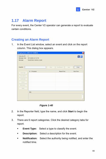
1.17 Alarm Report For every event, the Center V2 operator can generate a report to evaluate certain conditions.
Creating an Alarm Report 1. In the Event List window, select an event and click on the report
column. This dialog box appears.
Figure 1-40
2. In the Reporter field, type the name, and click Start to begin the report.
3. There are 6 report categories. Click the desired category tabs for report.
Event Type: Select a type to classify the event.
Description: Select a description for the event.
Notification: Select the authority being notified, and enter the notified time.
65

Arrival: The button becomes available after you select a notified authority. Enter the arrival time of the authority.
Measures: Select the measure taken to deal with the event.
Other: The button is available only when the e-mail and /or SMS alert are configured.
4. When you finish the report and will not change the contents, click the End Report. Or click Save to edit later.
Editing Alarm Report Categories The items in each category of the Alarm Report can be customized and edited to meet your needs. The changes made here are permanent, and will be available for the report creation. 1. On the Center V2 window, click the Preference Settings button, and
select Customize Alarm Report. This dialog box appears.
Figure 1-41 2. Click the desired category tab (Event Type, Description,
Measurement Taken, Patrol) to make the necessary changes.
3. Click OK to save the changes.
66

Center V2 1
Printing Alarm Reports You can print out the alarm reports along with filtered logs.
1. To open the Event Log Browser, click the Event List button (No.5, Figure 1-1) and select View Event Log.
2. To search desired events with the alarm reports, click the Filter button (No.4, Figure 1-24).
3. In the Filter dialog box, check the Clipboard icon and select the desired types of alarm reports from the drop-down list. It is also suggested to define other criteria for better search results.
4. Click OK. The search results will be displayed in the Event Log Browser window.
5. To set up the printout, click the Page Setup button. The Page Setup dialog box appears.
6. To print out the alarm reports along with the search results, check Print Managing Alarm Report and click OK.
Figure 1-42
7. To print out the search results, click the Print button. Find the alarm reports in the last part of the printouts.
67

1.18 Colorful Flags The flags of various colors are provided to distinguish different events. You will find them useful not only when browsing in the Event List but also when using the Filter function to search the desired events.
Figure 1-43
Marking the Events with Colorful Flags You can flag any events in the Event List for later reference. There are 6 kinds of flags and one check mark for you to signify the events.
1. On the Event List window, select one event, and right-click on the flag column. A list of 6 kinds of flags in different colors (Red Flag, Blue Flag, Yellow Flag, Green Flag, Orange Flag and Purple Flag), one check mark (Flag Complete) and two setting options appears.
2. Select the desired flag or check mark for the event.
To unmark the events, simply click the flag icon. Or right-click the flag icon and select Clear Flag.
68
Center V2 1
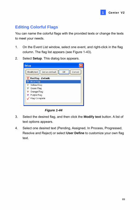
Editing Colorful Flags You can name the colorful flags with the provided texts or change the texts to meet your needs.
1. On the Event List window, select one event, and right-click in the flag column. The flag list appears (see Figure 1-43).
2. Select Setup. This dialog box appears.
Figure 1-44
3. Select the desired flag, and then click the Modify text button. A list of text options appears.
4. Select one desired text (Pending, Assigned, In Process, Progressed, Resolve and Reject) or select User Define to customize your own flag text.
69

1.19 Backup Servers You can configure up to two backup servers in case of the primary Center V2 server failure. Whenever the primary fails, the backup server takes over the connection from subscribers, providing uninterrupted monitoring services. 1. To import the subscribers’ accounts from the primary server to the
backup server, click the Import / Export Address Book button (No. 6, Figure 1-2) on the Address Book toolbar, and select Import to transfer the address book data.
2. On the Center V2 window, click the Preference Settings button (No.10, Figure 1-1), and select Automatic Failover Support. This dialog box appears.
Figure 1-45
70
Center V2 1
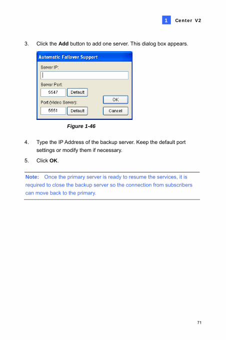
3. Click the Add button to add one server. This dialog box appears.
Figure 1-46
4. Type the IP Address of the backup server. Keep the default port settings or modify them if necessary.
5. Click OK. Note: Once the primary server is ready to resume the services, it is required to close the backup server so the connection from subscribers can move back to the primary.
71

1.20 Simultaneous Playback of Multiple Videos The Center V2 allows simultaneous playback of multiple video files using the video player EZPlayer. 1. Double-click an attached video file to open the EZPlayer.
1 2
5
3 4
6 7 8 9 10 11 12
Figure 1-47
No. Name Description
1 Tools Adds effects to the image, including the options of Brightness, Contrast, Smooth, Sharpen, Grayscale and Undo. The other options include Copy, Save As (an image or an .avi file), Print and Setup.
2 Zoom In Zooms in the video. 3 Zoom Out Zooms out the video. 4 Move Moves the EZ Player window. 5 Play Plays the video file. 6 Pause Pauses the video file. 7 Stop Stops the video file.
72

Center V2 1
8 Previous Frame Goes to the previous frame of the video file. 9 Next Frame Goes to the next frame of the video file. 10 Top Frame Goes to the beginning of the video file. 11 End Frame Goes to the end of the video file. 12 Speed Control Controls the play speed.
2. Click the Tools button on the top of the EZPlayer window, and click Setup from the pop-up menu. This dialog box appears.
Figure 1-48
Open each video in the same windows: This option allows you to view one video file at one time in the same player.
Open each video in its own windows: This option allows you to view multiple video files in their own players at the same time.
3. Check the option of Open each video in its own windows, and click OK.
To switch back to one-player mode, follow these steps: 1. Leave one EZPlayer and close the rest of the existing players on the
screen.
2. On the top of the EZPlayer window, click the Tools button (No.1, Figure 1-47) and click Setup from the pop-up menu.
3. Check the option of Open each video in the same windows, and click OK.
73

1.21 Controlling the PTZ Cameras Using GV-Joystick
You can control the PTZ cameras using GV-Joystick in Camera/Audio Control. Up to 4 GV-Joysticks can be connected to control the PTZ cameras. You need to run the following program in the background when using the GV-Joystick to control PTZ. 1. Run mcamctrl.exe from the Center V2 program folder. This dialog
box appears.
Figure 1-49
2. In the Port field, select the COM port connected to the GV-Joystick. Click the Start Service button ► and then you can use the GV-Joystick to control the PTZ camera.
3. If more than one GV-Joystick is connected, repeat Step 2 to set up and use another GV-Joystick.
For details on the GV-Joystick operations, see GV-Joystick User’s Manual.
74

Center V2
75
1
1.22 Specifications
Feature Note
Maximum of Subscribers (standard) 5
Maximum of Subscribers (professional) 500
Maximum of Channels (standard) 80
Maximum of Channels (professional) 800
Control of GV-Joystick Yes
Backup to CD/DVD Yes
Alarm Reports of Events Yes
Notification of SMS Alerts Yes
Notification of E-mail Alerts Yes
Notification of E-Map Alerts Yes
Automatic Connection Recovery Yes
Support for Mega Pixel Resolution Yes
Real-Time Monitoring Yes
Remote PTZ Control Yes
Remote I/O Control Yes
Product specifications are subject to change without notice.

Chapter 2 Dispatch Server
The availability of Center V2 Servers may be threatened by network overload. Thru Dispatch Server, the concern can be settled by arranging and distributing subscribers’ requests to the least busy Center V2 Servers. With Dispatch Server, a central monitor station can run several Center V2 Servers and serve a large number of subscribers with the fastest responding time. If any of Center V2 Servers needs maintenance, Dispatch Server can automatically redistribute subscribers’ requests to other Center V2 within a server farm or to servers in another location.

2.1 System Requirements
Before installation, make sure that your computer meets the following minimum requirements:
OS Windows 2000 / XP / Server 2003 / Vista CPU Pentium 4, 2.6 GHz, 800 MHz FSB Memory 2 x 256 MB Hard Disk 60 GB VGA NVIDIA GeForce4 MX440 64MB, 1024 x 768 screen resolutionNetwork TCP/IP
78

Dispatch Server 2
2.2 Installing Dispatch Server
1. Insert the CMS Software CD to your computer. It will automatically run and a window appears.
2. Select the Install V 8.2.0.0 Central Monitoring System item. 3. Click Dispatch Server System, and follow the on-screen instructions. Note: The Dispatch Server application is provided with a USB dongle. Make sure the dongle is tightly connected to the computer.
79

2.3 The Dispatch Sever Window 1 2 3 4 5 6 7 8 9
10
Figure 2-1
The controls on the Dispatch Server window: No. Name Description 1 Start Server Starts Dispatch Sever. 2 Stop Server Stops Dispatch Sever. 3 Server Setting Configures Dispatch Sever. 4 Account Adds, edits and deletes the accounts of Center V2
Servers and subscribers. 5 Subscriber Notification
Setting Sets the alert conditions and methods
6 Stop/Start Query Center V2 Event
Specifies an event query.
7 Real-time CenterV2 Event
Views real-time events occurring on Center V2 Servers.
8 Exit Closes the Dispatch Server window.
9 Center V2 Status The window displays the status of Center V2 Servers. A check appearing on the check box indicates the Center V2 Server is allowed to connect to Dispatch Server. Unchecking will disable the connection.
10 Tree View The list displays all created group folders, servers and subscribers. You can right click any online subscriber to call up Subscriber Address Book and Camera/Audio Control Panel.
80

Dispatch Server 2
2.4 Creating a Subscriber Account
Dispatch Server can serve up to 50 Center V2 Servers and 25,000 subscribers at the same time. Before starting the services, create at least one subscriber on the Dispatch Server. To create an account, click the Account button (No. 4, Figure 2-1) to display this Address Book window.
7 1081 2 3 4 5 6 9
Figure 2-2
The toolbar on the Address Book window:
No. Button Description 1 Add A Group Adds a group folder. 2 Add A Server Adds a server. 3 Add A Subscriber Adds a subscriber. 4 View/Edit Subscriber
Address Book Opens Subscriber Address Book for viewing and editing.
5 Subscriber Setting Highlight one subscriber and click this button to configure the settings of video and alert formats.
6 Subscriber Schedule Setting
Sets up subscription schedules
7 Delete A Group/Server/Subscriber
Highlight a group, a server or a subscriber and click this button to delete it.
8 Import / Export Address Book
Imports or exports the address book data.
9 Find A Subscriber Searches a subscriber account. 10 Find A Server Searches a server account.
81
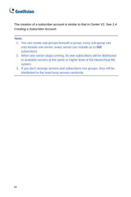
The creation of a subscriber account is similar to that in Center V2. See 1.4 Creating a Subscriber Account. Note: 1. You can create sub-groups beneath a group; every sub-group can
only include one server; every server can include up to 500 subscribers.
2. When one server stops running, its own subscribers will be distributed to available servers at the same or higher level of the hierarchical file system.
3. If you don’t arrange servers and subscribers into groups, they will be distributed to the least busy servers randomly.
82

Dispatch Server 2
2.5 Creating a Subscription Schedule
The Dispatch Server operator can create schedules to monitor subscription status. When subscribers don’t log in Dispatch Server on the programmed time, the operator and subscribers will get notified.
• To set up a schedule, see 1.4 Creating a Subscription Schedule. • When a subscriber doesn’t log in Dispatch Server on time, this
message will appear on the Event List: Subscriber session is not established. Wait-Time expired. When a subscriber logs out suddenly during a service time, this message will appear: Unexpected logout before subscriber session is completed.
• To notify subscribers by SMS and E-Mail, see 2.13 SMS Alerts and
2.14 E-Mail Alerts.
83
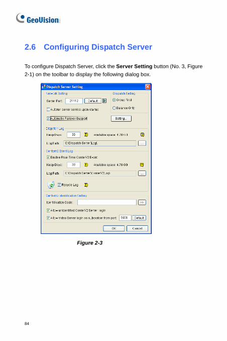
2.6 Configuring Dispatch Server
To configure Dispatch Server, click the Server Setting button (No. 3, Figure 2-1) on the toolbar to display the following dialog box.
Figure 2-3
84

Dispatch Server 2
[Network Setting] Server Port: The port should match with the Center Port of the
subscriber (Figure 1-13) and Dispatch Server Port of Center V2 (Figure 2-4) (All the three ports should match with each other). Or, keep the port setting as default.
Autorun server service upon startup: Automatically starts the Dispatch service when its program starts.
Automatic Failover Support: Distributes Center V2 Servers to another Dispatch Server when the serving Dispatch Server breaks down. Enabling this item, you will be prompted to enter the IP address and port of another Dispatch Server. For details, see 2.15 Backup Servers.
[Dispatch Setting] Group First: Distributes subscribers to the Center V2 Servers
according to the assigned groups and servers. Balance Only: Distributes subscribers to the Center V2 Servers with
fewer subscribers randomly. [Dispatch Log] Keep Days: Specify the days of the Dispatch log kept in the HDD
from 1 to 999 days. Log Path: Click the button next to the item to assign a storage path.
[CenterV2 Event Log] Enable Real-Time CenterV2 Event: Allows real-time event
messages coming from Center V2 Servers. Keep Days: Specify the days of the Center V2 event log kept in the
HDD from 1 to 999 days. Log Path: Click the button next to the item to assign a storage path.
[Recycle Log] Deletes the files of the oldest days when storage space is lower than 500MB.
85

[CenterV2 Identification Setting] Identification Code: The code protects Dispatch Server against
unauthorized Internet access. Center V2 will need the code to log in Dispatch Server.
Allow unidentified CenterV2 Server login: Allows Center V2 to access Dispatch Server without entering the Identification Code.
Allow Video Server login as subscriber from port: Enables the connection to the GV-Video Server or GV-IP Camera. The default port is 5551, or you can modify it to match the Center V2 port on the GV-Video Server or GV-IP Camera. For details, see GV-Video Server User’s Manual or GV-IP Camera User’s Manual.
2.7 Starting Dispatch Server
After subscriber accounts are created, Dispatch Server is ready to provide services. Click the Start Server button (No. 1, Figure 2-1) on the Dispatch window to start the services.
86

Dispatch Server 2
2.8 Connecting Center V2 to Dispatch Server
Follow these steps to connect Center V2 to Dispatch Server: 1. Start the Dispatch Server service.
2. At Center V2, click the Preference Settings button, select System Configure to display the Preference window, and then click the Dispatch Server tab. This dialog box appears.
Figure 2-4
[Dispatch Server] Check the Use Dispatch Server item to make other settings available. Enter the identification code, IP address, and port of the Dispatch Server. See Figure 2-3.
[Connection Broken] Enable and specify the interval between connection retries.
3. If you have arranged Center V2 servers and subscribers into groups in Dispatch Server, click the Network tab in Figure 2-4 and check the Location Name of the Center V2. The location name should match the server name created on Dispatch Server.
4. After above settings, click OK and restart Center V2.
87

2.9 Connecting GV-System to Dispatch Server
By default, GV-System is set to connect to Center V2. You need to reset GV-System so that it can connect to Dispatch Server. Follow these steps to connect GV-System to Dispatch server:
1. In the main screen of GV-System, click the Network button, and then select Connect to Center V2. The Login Information dialog box appears. See Figure 1-15.
2. In the Center IP field, type the IP address of the Dispatch Server. 3. Type a valid user ID and password created in the Dispatch Server. 4. Change the port number from 5547 (Center V2 port) to 21112
(Dispatch Server port). 5. Click the Next button. The Connect to Center V2 dialog box appears. 6. Click the Connect button to enable connecting to the Dispatch Server. Note: If you want to modify the login information of the Center V2, on the Connect to CenterV2 dialog box click the listed Center V2 IP and then select Modify.
88

Dispatch Server 2
2.10 Querying an Event on Center V2
This feature lets you locate a desired event by posing a query on Center V2 Servers. Click the Stop/Start Query Center V2 Event button (No. 6, Figure 2-1) on the toolbar to display the following dialog box. Check the desired query items (Type, ID, Date and/or Time), define your query condition under each item, and then click OK to display the query results.
Figure 2-5
The Query feature supports the remote playback when file sharing on Center V2 Server is enabled. Double-clicking any found event with video attachment can play it back on Dispatch Server.
89

2.11 Displaying Real-Time Events of Center V2
The feature lets you view the real-time events occurred on Center V2 Servers. For the application, make sure the Enable Real-Time CenterV2 Event option is enabled; see Figure 2-3. Then click the Real-Time Event button (No. 7, Figure 2-1) on the toolbar to display the following window.
Figure 2-6
The controls on the Real-Time Center V2 Event window: 1. The window supports the remote playback when file sharing on the
Center V2 Server is enabled. Double-clicking any event with video attachment can play it back on Dispatch Server.
2. You can flag an incoming event for later reference. Click in the flag column to flag an event. Click the flag icon to remove it.
90

Dispatch Server 2
A list of Types and Messages from Center V2 will be displayed:
Type Message Motion Camera detected motion Trigger I/O Trigger; Module xx Trigger Resume; Video of Camera xx
(By: Module xx) Connection Video Lost; Module Lost; The network connection is lost; The
connection of (client xx) is abnormal; Camera cannot be controlled; Ping Timeout; Failed to establish the connection; Video signal of Camera xx has resume; Module xx has returnedto normal; Failed to Login SMS Server; Failed to send short message; SMS Server is shutdown.
Alarm There isn't enough space for recording; There isn't enough space for recording; The storage for Event Log is low, Event Log will not take any new entries; An unexpected error occurred in Multicam Surveillance System (Error Code: 1 or 2); There is an intruder; Object Missing; Unattended Object; Alert Message of POS.
Attachment Record file of Camera xx [Live, Attachment or offline]. System Start Recycle; Recycle Event Log; Status change of monitoring
cameras. On: (camera no.) Off: (camera no.) / (By Schedule); Stop all cameras monitoring; Start all cameras monitoring; Start I/O Monitoring. / (By Schedule); Stop I/O Monitoring. / (By Schedule); Schedule Start; Schedule Stop. All monitoring devices are stop too; Start monitoring all type events; Stop monitoring all type events; Subscriber session is not established. Wait-time expired; Unexpected logout before subscriber session is completed.
Note: Error Code 1 indicates a codec error; Error Code 2 indicates that users can’t write or record any data due to HD failure or user privilege.
91

Colorful Flags The flags of various colors are provided to distinguish different events. You will find them useful not only when browsing in the Real-Time CenterV2 Event List window but also when using the Filter function to search the desired events.
Figure 2-7
This feature is the same as that of the Center V2. For details, see 1.18 Colorful Flags.
92

Dispatch Server 2
2.12 Launching Log Browser
The following two log browsers let you locate the events of Dispatch Server and Center V2 Servers easily.
Dispatch Log Browser The browser lets you view and locate the system status of Dispatch Server, the login/out status of Center V2 Servers. Click View on the window menu and then select Dispatch Log to display the following log browser. For details on Log Browser, see 1.8 Event Log Browser.
Figure 2-8
A list of Status and Messages will be displayed:
Status Message System Start Dispatch Server; Failed to start Dispatch Server; Stop
Dispatch Server; Can't find KeyPro; Start to recycle the Dispatch Server; Start to recycle the CenterV2 Event Log.
Login/logout CenterV2 Server (IP: CS_IP) connects to Dispatch Server; CenterV2 Server (IP: CS_IP) disconnects from Dispatch Server;CenterV2 Server (IP: CS_IP) disconnects from Dispatch Server abnormally; CenterV2 Client login; CenterV2 Client logout
Connection CenterV2 Server (IP: CS_IP) is disconnected by Dispatch
93

Server; CenterV2 Server changes IP from (CS_old_IP) to (CS_new_IP); CenterV2 Server (IP: CS_IP) is transferred to another Dispatch Server (DS_IP:DS_Port).
Control CenterV2 Server [CS_Name] is enabled; CenterV2 Server [CS_Name] is disabled.
Dispatch ID: login_ID is dispatched to [CS_Name] (IP: CS_IP); Invaild login ID; Invaild login Password; This account has already logged in; There is no server online for CenterV2 Client; All online CenterV2 Servers have utmost service.
Event Log Browser The browser lets you view and locate the real-time events from Center V2 Servers. Click View on the window menu, and then select Event log to display Event Log Browser. For details on Log Browser, see 1.8 Event Log Browser.
94

Dispatch Server 2
2.13 SMS Alerts This feature automatically sends SMS messages to subscribers when they don’t log in on the programmed time. For this, ensure to type a mobile number for each subscriber in the Subscriber Address Book (Figure 2-2). To set up SMS Server, click Configure on the window menu and select SMS Setup. For details, see 1.14 SMS Alerts. To define alert conditions to send SM messages, click the Subscriber Notification Setting button (No. 5, Figure 2-1) on the toolbar to display the Notification Setting dialog box. For setup details, see 1.13 Notification Settings.
2.14 E-Mail Alerts This feature automatically sends e-mails to subscribers when they don’t log in on the programmed time. For this, ensure to type a e-mail address for each subscriber in the Subscriber Address Book (Figure 2-2). To set up mailbox, click Configure on the window menu and select E-Mail Setup. For details, see 1.15 E-Mail Alerts. To define alert conditions to send e-mails, click the Subscriber Notification Setting button (No. 5, Figure 2-1) on the toolbar to display the Notification Setting dialog box. For setup details, see 1.13 Notification Settings.
95

2.15 Backup Servers You can configure up to two backup servers in case of the primary server failure. Whenever the primary fails, the backup server takes over the connection from subscribers, providing uninterrupted services. 1. To import the subscribers’ accounts from the primary server to the
backup server, click the Import / Export Address Book button (No. 8, Figure 2-2) on the Address Book toolbar, and select Import to transfer the address book data.
2. On the Dispatch Server window, click the Server Setting button (No. 3, Figure 2-1). The Dispatch Server Setting dialog box (Figure 2-3) appears.
3. Check the Automatic Failover Support option. The Automatic Failover Support dialog box appears.
Figure 2-9
4. Click the Add button. The Setting dialog box (Figure 2-10) appears. 5. Type the IP address of the backup server, and change the default port
settings if necessary. 6. Type the Identification Code matching to that in CenterV2 Identification
Setting. If the information is inconsistent, the connection to the backup server cannot be established.
96

Dispatch Server 2
Type the same Code here.
Figure 2-10
Note: Once the primary server is ready to resume the services, it is required to close the backup server so the connection from subscribers can move back to the primary
97

98
2.16 Specifications
Feature Note
Maximum No. of Channels 40,000
Maximum No. of Subscribers 25,000
Maximum No. of Center V2 50
Maximum No. of Sensors / Alarms 3,600,000
Real-Time Audio Monitoring Yes
Remote PTZ Control Yes
Remote I/O Control No
Auto Recording No
Event List Viewer Yes
Event List Filter Yes
Dual Monitor Support No
Network Load Support Yes
Automatic Connection Recovery Yes
Product specifications are subject to change without notice.

Chapter 3 Vital Sign Monitor Vital Sign Monitor (VSM) applies to the center monitoring station where multiple GV-Systems are being monitored. When alert events occur in a GV-System, VSM will receive alert text messages, computer alarms and/or output alarms, while a SMS message and an E-Mail are sent out to subscribers.

3.1 System Requirements
Before installation, make sure your PC meets the following minimum requirements:
OS Windows 2000 / XP/ Server 2003 / Vista CPU Pentium 4, 2.6 GHz, 800 MHz FSB Memory 2 X 256 MB Hark Disk 60 GB VGA NVIDIA GeForce4 MX440 64 MB, 1024 x 768 screen resolutionNetwork TCP/IP To ensure the quality of downloading when multiple GV-Systems connect to the VSM, see the list below for the recommended bandwidth:
Number of Subscribers Recommended Bandwidth 100 512 Kbps 500 2 Mbps 1000 4 Mbps
100

Vital Sign Monitor 3
3.2 Installing VSM
1. Insert the CMS Software CD to your computer. It will automatically run and a window appears.
2. Select the Install V 8.2.0.0 Central Monitoring System item. 3. Click Vital Sign Monitor System, and follow the on-screen
instructions.
Note: The VSM application is provided with a USB dongle. Make sure the dongle is tightly connected to the computer.
101

3.3 The VSM Window 181713 15 16
20
19
1 62 3 4 5 107 98 111412
Figure 3-1
The controls on the VSM window:
No. Name Description 1 Start / Stop Service Starts or stops the VSM service. 2 Account Adds, deletes or modifies subscribers. 3 Show /
Hide Subscriber List Shows and hides the Subscriber List.
4 View Event Log Launches Event Log Browser. 5 Force Output Activates manually output devices to alert the
VSM operator. 6 View Subscriber
Information Accesses the subscriber’s storage and monitoring information.
102

Vital Sign Monitor 3
7 ID Enter an ID for further search. 8 View Subscriber
Address Book Enter an ID, and then click this button to view the subscriber’s address book.
9 View Subscriber Status Enter an ID, and then click this button to see the subscriber’s status.
10 Send E-Mail Sends e-mails to subscribers. 11 Send Short Message Sends SMS to subscribers. 12 Flag Flags an event for later reference. 13 Clipboard Displays the Alarm Report dialog box. 14 ID Indicates the subscriber’s ID. 15 Type Indicates the event types, including System,
Connection, Login/Logout, Motion, Trigger, and Alarm.
16
Message Indicates associated information for each event type.
17 Message Time Indicates the VSM’s time when receiving the event message.
18 Start Time Indicates the subscriber’s time when sending out the event message.
19 Subscriber List Displays all created groups and subscribers. Right clicking any subscriber can call up a menu to select the control No. 8, 9,10 and 11.
20 Event List Displays a list of events occurred.
103

A list of Types and Messages will be displayed on VSM:
Type Message Motion Camera xx detected Motion.
Trigger Module xx-Input xx Triggered; Module xx-Input xx Trigger Resume.
Connection
Camera xx Video Lost; Video Signal of Camera xx has resumed; Module xx Lost; Module xx has resumed to normal.
Alarm There isn’t enough space for recording; Connection Lost; Multicam Surveillance System has been closed; Status change of monitoring cameras: on: camera xx, off: camera xx; Keep Days (xx) Alarm of Video Log is lower than xx days; Schedule Start/Stop; An unexpected error occurred in Mulicam Surveillance System (Error Code: 1 or 2); There is an intruder; Missing Object; Unattended Object; Alert Message of POS; Scene Change.
Login/Logout Login; Logout.
System Start/End Service; Fail to Start Service; Stop all camera monitoring; Start all camera monitoring; Start monitoring all type events; Stop monitoring all type events; Subscriber session is not established. Wait-time expired; Unexpected logout before subscriber session is completed; Can’t find USB Protection Key.
Note: Error Code 1 indicates a codec error; Error Code 2 indicates that users can’t write or record any data due to HD failure or user privilege
104

Vital Sign Monitor 3
3.4 Creating a Subscriber Account
The VSM can serve up to 1,000 subscribers at a time. Create at least one subscriber before starting VSM services. To create a subscriber, follow these steps:
1. On the VSM widow, click the Account button (No. 2, Figure 3-1) to display the Address Book window.
Figure 3-2
2. Click the Add A Group button to create a group folder. 3. Click the Add A Subscriber button to display the Subscriber
Address Book dialog box.
4. Enter a login ID and password (required). Those will be the ID and Password for the subscriber to log in to the VSM. See Figure 3-4.
5. Enter the subscriber’s contact information in the rest of fields (optional).
If you wish to send e-mail alerts to this subscriber, type its e-mail address. For e-mail settings, see E-Mail Alerts later in this chapter.
If you wish to send SMS alerts to this subscriber, type its country code and mobile number. For SMS server settings, see SMS Alerts later in this chapter.
6. Click OK. This adds the subscriber to the group folder created before. Returning to the VSM window, you will see a message: Add a subscriber – xxx. (Subscriber xxx has been added.)
105

3.5 Creating a Subscription Schedule
The VSM operator can create schedules to monitor subscription status. When subscribers don’t log in the VSM on the programmed time, the operator and subscribers can get notified.
• To set up a schedule, see 1.5 Creating a Subscription Schedule.
• When a subscriber doesn’t log in the VSM on time, this message will appear on the Event List: Subscriber session is not established. Wait-Time expired. When a subscriber logs out suddenly during a service time, this message will appear: Unexpected logout before subscriber session is completed.
• To activate the computer and output alarm to notify the operator while a SMS and E-mail message being sent out to a subscriber, use the Notification feature. For details, see Notification Settings later in this chapter.
106

Vital Sign Monitor 3
3.6 Configuring VSM
On the window menu, click Configure to see these options: (1) System Configure, (2) Password Setup, (3) Event Log Settings, (4) Notification and (5) Local I/O Device. These options are discussed in this section.
System Configuration Click Configure on the window menu, and then select System Configure to open this dialog box:
Figure 3-3
107

[Startup] Auto Run when Windows starts: Automatically runs VSM at
Windows startup. Start Service when Vital Sign Monitor starts: Automatically starts
the service when VSM starts. Login SMS Server when Service starts: Automatically logs in the
SMS Server when the VSM service starts. You will be prompted to enter the related information of the SMS server.
[Connective Port] Sets the communication port to match that of the subscriber, or keep it as default. [Connective Port for Video Server] To set the appropriate port for the connection to the GV-Video Server or GV-IP Camera, keep the default port 5609, or modify it to match the VSM port on the GV-Video Server or GV-IP Camera. For details, see GV-Video Server User’s Manual or GV-IP Camera User’s Manual. [Camera Motion] Post-Motion: Specify the duration of the highlighted text for the
incoming message upon motion detection. Alerts Interval: Enable and specify the interval between the
incoming messages upon motion detection. [Enhance network security] Enable to enhance Internet Security. Please notice when this feature is enabled, the subscribers using earlier version than version 7.0 cannot access the VSM any more. [Arrow Button] The arrow buttons, in the Connective Port and Connective Port for Video Server items, provide the UPnP function to configure the ports on your router automatically. For details, see UPnP Settings, Chapter 6, User’s Manual on the Surveillance System Software CD.
108

Vital Sign Monitor 3
Password Settings You can set an administrator password to prevent others from changing your settings by accident. Click Configure and then select Password Setup.
To start the password feature, click Service and then select Logout Administrator. Users can still start monitoring but will not be allowed to change settings or stop monitoring. To change settings, click Service on the window menu and then select Login as Administrator.
Event Log Settings Click Configure on the window menu, and select Event Log Settings to display the Event Log Settings dialog box. The settings are the same as those in Center V2. See Event Log Settings, 1.8 Event Log Browser.
Also see 3.9 Event Log Browser.
Notification Settings When alert conditions occur, the VSM can automatically activate the assigned computer and output alarm to notify the operator while a SMS and e-mail message being sent out to subscribers.
For this application, click Configure on the window menu and select Notification to display the Alarm Settings window. The settings are the same as those in Center V2. See 1.13 Notification Settings.
Also see 3.11 Output Alerts, 3.12 SMS Alerts, and 3.13 E-Mail Alert.
109
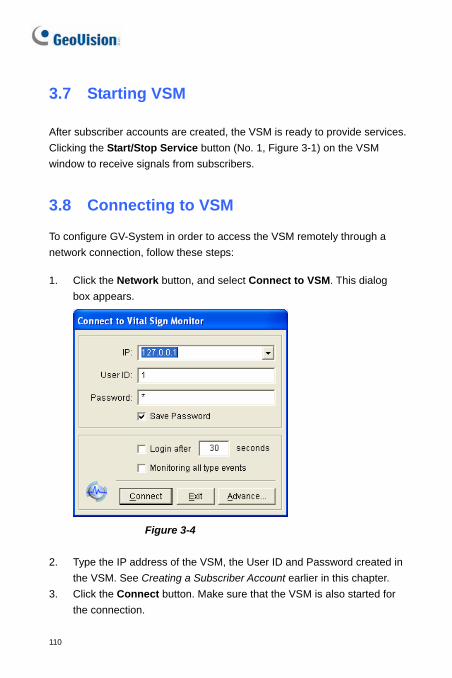
3.7 Starting VSM
After subscriber accounts are created, the VSM is ready to provide services. Clicking the Start/Stop Service button (No. 1, Figure 3-1) on the VSM window to receive signals from subscribers.
3.8 Connecting to VSM
To configure GV-System in order to access the VSM remotely through a network connection, follow these steps:
1. Click the Network button, and select Connect to VSM. This dialog box appears.
Figure 3-4
2. Type the IP address of the VSM, the User ID and Password created in the VSM. See Creating a Subscriber Account earlier in this chapter.
3. Click the Connect button. Make sure that the VSM is also started for the connection.
110

Vital Sign Monitor 3
Advanced Settings for Subscription To further define the communication conditions between the subscriber and VSM, click the Advance button on the Connect to Vital Sign Monitor dialog box (Figure 3-4) to display the Advanced Settings dialog box. There are these tabs on it: (1) General, (2) Camera, (3) System Information and (4) I/O Device. [General] The settings define the retry mode and communication port between GV-System and VSM.
Figure 3-5
[Connective Port] Sets the communication port to match that of VSM. [Connection Broken] Specify the number of retries and the retry interval when the connection is not immediately available. Retry until connected: Attempts to connect to the VSM until the
connection is established. Retry in the background: Hides the retries in the background.
111

[Camera] The settings define which camera condition to notify the VSM. To configure the even type, first disable the Monitoring all type events option in Figure 3-4.
Figure 3-6
Notify Vital Sign Monitor when Motion is Detected: Notifies the VSM when any selected camera detects motion. Click the Set Camera(s) button to select desired cameras for the application.
Event Type: If the subscriber wants the VSM always to get notified of motion detection, select Emergency. If the subscriber wants the VSM to get notified of motion detection only when an assigned input is triggered, select Normal.
Notify Vital Sign Monitor when the following events come up: Notifies the VSM when any alert event occurs, including Intruder, Missing Object, Unattended Object and Scene Change.
Event Type: If the subscriber wants the VSM always to get notified of these alert events, select Emergency. If the subscriber wants the VSM
112

Vital Sign Monitor 3
to get notified of these alert events only when an assigned input is triggered, select Normal.
Note: To set an input trigger for the notification of Normal events, see Security Service in [I/O Device] below.
[System Information]
Figure 3-7
113

[Video/Audio Log] Notifies the VSM when the duration of the video/audio logs is less than the specified days.
[Storage Information] Allow Vital Sign Monitor to inquire the storage information:
Allows the VSM to inquire the subscriber’s storage information. Report the total amount of free storage space to Vital Sign
Monitor: Reports the subscriber’s size of free storage space. Notify Vital Sign Monitor when the total amount of free space is
lower than xx GB: Notifies the VSM when the subscriber’s storage space is insufficient. The space limit is 1 GB at least.
Notify Vital Sign Monitor when the storage space was full: Notifies the VSM when the subscriber’s storage space was full.
[Other] Time synchronization with Vital Sign Monitor: Enables the time
increment/decrement of minutes and seconds at the subscriber site to match the time at the VSM.
Send Alert Message of POS’ Loss Prevention to Vital Sign Monitor: Notifies the VSM when abnormal POS transactions occur.
Notify Vital Sign Monitor when the user fails to log in Multicam: Notifies the VSM when the GV-System users fail to log in by typing wrong IDs or passwords
Notify Vital Sign Monitor when the USB Protection Key was removed: Notifies the VSM when the USB Protection Key is already removed from the GV-System.
Note: When the Time synchronization with Vital Sign Monitor option is checked, the function of time synchronization will be activated as soon as the VSM is started up, and it will be re-activated every 12 hours.
114

Vital Sign Monitor 3
[I/O Device] The settings define which I/O condition to notify the VSM. To configure these settings, first disable the Monitoring all type events option in Figure 3-4.
Figure 3-8
[I/O Device] Notifies the VSM when I/O devices are triggered. Use the Arrow buttons to configure each I/O device, or click the Finger button to apply to all I/O devices.
Allow Vital Sign Monitor to Enable / Disable I/O: Allows the VSM manually arm/disarm any I/O devices at the subscriber’s site without interrupting the monitoring. For example, when an alarm is triggered at the subscriber site, the VSM operator can turn it off remotely before arriving at the site. Meanwhile, GV-System still remains on monitoring.
115

Notify Vital Sign Monitor when I/O is Triggered: Notifies the VSM when any selected input is triggered.
Event Type: If the subscriber wants the VSM always to get notified of the input trigger, select Emergency. If the subscriber wants the VSM to get notified of the input trigger only when an assigned input is triggered, select Normal.
Right Arrow button: Sets the delay time to notify the VSM of the input trigger. This feature is only available when the Normal type is chosen.
Exit Delay: While the system is activated, this feature provides an interval of time for the subscriber to exit the premises. During this time, the specified input (e.g. an exit/entry door) is inactive. Once the exit delay expires, the input will be fully armed.
Entry Delay: While the system is activated, this feature provides an interval of time for the subscriber to entry the premises. During this time, the specified input (e.g. a exit/entry door) is inactive so that the subscriber can disarm the system. If the subscriber fails to do, once the entry delay expires, the VSM will get notified of the input trigger.
Output Module: Enables the assigned output module when the
selected input module is triggered. For this example, when the I/O Device (Module 1, Input 4) is triggered, the Output (Module 1, Pin 3) will be activated simultaneously.
Event Type: If the subscriber wants the VSM always to get notified of the output trigger, select Emergency. If the subscriber wants the VSM to get notified of the output trigger only when an assigned input is triggered, select Normal. Right Arrow button: Sets the delay time to trigger the assigned output module. This feature is only available when the Normal type is chosen. The Exit Delay and Entry Delay options are similar to those described in the input trigger.
116

Vital Sign Monitor 3
Note: To set an input trigger for the notification of Normal events, see [Security Service] below.
Allow Vital Sign Monitor to Force Output: Allows the VSM
operator to manually force output devices installed at the subscriber’s site.
[Security Service] Supports two types of access control systems: Momentary and Maintained mode. For details, see [I/O Device] in 1.7 Connecting to Center V2. Detecting Input Status The feature is designed to monitor all inputs for a change of state whenever the subscriber starts the VSM monitoring. A change from the previously defined state (N/O to N/C or N/C to N/O) will activate an alarm condition. Click on the Connect to Vital Sign Monitor dialog box (Figure 3-4). For details, see Detecting Input Status, Chapter 2, User’s Manual on the Surveillance System Software CD.
3.9 Event Log Browser
To launch Event Log Browser, click Tools on the window menu and select Event Log Browser. This feature is the same as that in Center V2. See 1.8 Event Log Browser.
Also see Event Log Settings earlier in this chapter.
117

3.10 Monitoring Subscribers Viewing Subscriber Status To view the subscriber status, highlight one online subscriber on the VSM window, and then click the View Subscriber Status icon (No. 9, Figure 3-1) on the toolbar. The following window appears.
Figure 3-9
[Subscriber] Indicates the subscriber’s ID. You can change the subscriber by clicking the […] button.
[Video Log Storage] Indicates the information of video log and hard disk space. To view the detailed information of multiple storage groups on the subscriber, click the […] button.
For this, subscribers must grant the privilege first. See [System Information] in Figure 3-7.
[Status] Indicates the icon meanings.
118

Vital Sign Monitor 3
[I/O Device] Force Output: To enable this tab, highlight one output from the tree
list, and click this tab to force the output at the subscriber site. For this, the subscriber must grant the privilege first. See the Allow Vital Sign Monitor to Force Output option in Figure 3-8.
Enable/Disable I/O: Allows the VSM to arm or disarm any I/O devices at the subscriber site without interrupting the monitoring. For this, the subscriber must grant the privilege first. See the Allow Vital Sign Monitor to Enable / Disable I/O option in Figure 3-8.
Viewing Storage Information With the above Subscriber Status window, you can see one subscriber’s storage information. When the VSM is monitoring many subscribers, the following windows give you an overview of subscribers’ storage information and monitoring status. On the VSM window, click the View Subscriber Information button (No 6, Figure 3-1) to display the following window.
[Monitoring] Indicates whether camera and I/O monitoring are enabled at the subscriber’s sites.
Figure 3-10
119

[Storage] Indicates the total storage size and free space at the subscriber’s sites. For this subscribers must grant this privilege first. See [System Information] in Figure 3-7.
Figure 3-11
Subscription Control The VSM operator can disable its services to an individual subscriber when subscription expires. On the Address Book (Figure 3-2), right-click one subscriber and select Disable. To restore the subscription, right-click again to select Enable.
120

Vital Sign Monitor 3
3.11 Output Alerts When alert conditions occur, you can activate the output devices installed either at the VSM site or at the subscriber site. Forcing Outputs of VSM To configure output devices at the VSM site, click Configure on the window menu and then select Local I/O Device. Currently the application only supports GV-IO modules. For setup details, see Setting Up I/O Devices, Chapter 2, User’s Manual on the Surveillance System Software CD. To automatically force outputs when alert conditions occur, see Notification Settings earlier in this chapter. To manually force outputs, click the I/O Device button (No. 5, Figure 3-1) on the VSM window, and then select Force Output to display the Force Output of Local I/O Device window. Select a desired module and then click Finger buttons to activate outputs.
Forcing Outputs of a Subscriber See Viewing Subscriber Status earlier in this chapter.
121

3.12 SMS Alerts This feature lets you send out SMS messages to subscribers when alert conditions occur. Setting SMS Server Before sending SMS messages to an individual subscriber, you need to define SMS Server correctly.
Click Configure on the window menu and select SMS Setup. For setup details, see 1.14 SMS Alerts.
Sending SMS Once the connection between the SMS Server and VSM is established, there are several ways to send out SMS messages to subscribers. See the VSM window for the following selections. 1. Click the Send Short Message button (No. 11, Figure 3-1). This sends
out SMS to an individual subscriber manually. 2. On the Event List, double-click any event type to call up a message
window, and then click the Send Short Message icon. This sends SMS to an individual subscriber manually.
3. On the Subscriber List (No. 18, Figure 3-1), right-click one subscriber and select Send Short Message. This sends SMS to an individual subscriber manually.
4. Click Configure on the window menu, and select Notification to display the Alarm Settings window. Check Send SMS Alerts. This sends SMS to subscribers automatically when alert conditions occur. See Notification Settings earlier in this chapter.
122

Vital Sign Monitor 3
3.13 E-Mail Alerts You can send e-mails to subscribers when alert conditions occur. Setting Mailbox Before you can send e-mails to an e-mail account, you need to define your mailbox correctly. Click Configure on the window menu and select E-Mail Setup. For setup details, see 1.15 E-Mail Alerts. Sending E-Mail There are several ways to send e-mail alerts. See the VSM window for the following selections. 1. Click the E-Mail button (No. 10, Figure 3-1). This sends the e-mail to
an individual subscriber manually. 2. On the Subscriber List (No. 18, Figure 3-1), right-click one subscriber,
and then select Send E-Mail. This sends the e-mail to an individual subscriber manually.
3. On the Event List, double-click one event to call up a message window, and then click the e-mail icon. This sends the e-mail to an individual subscriber manually.
4. Click Configure on the window menu and select Notification to display the Alarm Settings window. Check Send E-Mail Alerts. This sends e-mails to subscribers automatically when alert conditions occur. See Notification Settings earlier in the chapter.
123

3.14 Backup Servers You can configure up to two backup servers in case of the primary VSM server failure. Whenever the primary fails, the backup server takes over the connection from subscribers, providing uninterrupted monitoring services. To access this feature, on the VSM window menu (see Figure 3-1), click Service, and select Automatic Failover Support. This feature is the same as Center V2’s. For details on setup, see 1.19 Backup Servers.
3.15 Alarm Report For every event, the VSM operator can generate a report to evaluate certain conditions. This function is the same as that of the Center V2. For details, see 1.17 Alarm Report.
3.16 Virtual I/O Support If subscribers enable the Virtual I/O function to control I/O devices connected from GV-Video Server and GV-Wiegand Capture, the VSM can also control these added I/O devices during the connection. For details, see Virtual I/O Control, Chapter 2, User’s Manual on the Surveillance System Software CD.
124

Vital Sign Monitor 3
3.17 Remote Playback You can retrieve the recordings from the DVR or video server, and play them back. The following function must be enabled ahead to allow remote access: • DVR: Enable recoding and Remote ViewLog Service on Control
Center Server • Video Server: Enable recording and the Remote ViewLog function 1. On the Event List, double-click one camera-related event. A message
window appears.
2. Click the Remote Playback icon. A setting dialog box appears.
3. Select the desired camera to be viewed, enter the ID and password to log in the DVR, and then click OK. The Remote Playback window appears.
4. For the controls on the Remote Playback window, see 4.14 Instant Playback.
125

126
3.18 Specifications
Feature VSM Center V2 Pro
Subscriber 1,000 500
Group Yes Yes
Bandwidth 4Mbps 25Mbps
Record Mode No Live / Attachment / Both
Live Subscriber Status Yes No
Auto Login Yes Yes
I/O Control Yes Yes
SMS Message Yes Yes
Time Synchronization Yes Yes
Keep Day Notify Yes No
Event Message Yes Yes
Notification Setting Yes Yes
Event Log Yes Yes
Connection Lost Detection Yes Yes
I/O Device Support Yes Yes
Subscriber storage Info. Yes No
Product specifications are subject to change without notice.

0BChapter 4 Control Center Control Center is a central monitoring station solution (CMS) that provides the CMS operator with these major features: • Access to client DVRs (See Remote DVR) • Access to remote desktops (See Remote Desktop) • Display of up to 96 cameras from different DVRs on the same screen
(See Matrix View) • Remote playback (See Remote ViewLog) • Central management for I/O devices from different DVRs (See I/O
Central Panel) • Monitor up to 36 Matrix views with 3840 cameras over the network
(See IP Matrix) • Video motion detection (See VMD Monitoring) • Instant Playback (See Instant Playback) • Picture-in-Picture and Picture-and-Picture views (See PIP and PAP
View) • Panorama View (See Panorama View)

128
1B4.1 System Requirements Before installation, make sure your computer meets the following minimum requirements:
Standard Specifications
OS Windows 2000 / XP / Server 2003 / Vista CPU Pentium 4, 3.0 GHz, 800 MHz FSB RAM 2 x 512 MB Hard Disk 80 GB VGA NVIDIA GeForce FX5200 or ATI Radeon 9550 or above Network TCP/IP Advanced Specifications Control Center runs with 4 Matrix views OR connects more than 150 channels. OS Windows 2000 / XP / Server 2003 / Vista CPU Intel Core2 Duo E6600, 2.4 GHz RAM 2 x 1 GB Hard Disk 80 GB VGA NVIDIA 7600GT x 2 or ATI X1650 x 2 or above Network TCP/IP Professional Specifications Control Center runs with 4 Matrix views AND connects more than 250 channels. OS Windows 2000 / XP / Server 2003 / Vista CPU Intel Core2 Quad Q6600, 2.4 GHz RAM 2 x 2 GB Hard Disk 80 GB VGA NVIDIA 7600GT x 2 or ATI X1650 x 2 or above Network TCP/IP

Control Center
129
4
2B4.2 Installing Control Center 1. Insert the CMS Software CD to your computer. It will automatically run
and a window appears. 2. Select the Install V 8.2.0.0 Central Monitoring System item. 3. Click Control Center System, and follow the on-screen instructions. Note: • The Control Center application is provided with a USB dongle.
Make sure the dongle is tightly attached to your computer.
• To run the Control Center of version 8.2.0.0, you must upgrade the NVIDIA driver to version 6.14.11.6371 or above if the NVIDIA Graphic Card is in use.
.

130
3B4.3 The Control Center Toolbar
51 2 3 4
Figure 4-1
The buttons on the Control Center Toolbar:
No. Name Description
1 Host List Opens the Host List to create and edit DVR hosts.
2 Group List Opens the Group List to group cameras from different DVRs.
3 IP Matrix List See 4.12 IP Matrix.
4 Edit Opens the Edit toolbar to display other buttons: Search Host, Configure, Save and Delete. The Add Host button only appears after the Host List is opened.
5 Service See the section of Service Toolbar.

Control Center
131
4
22BThe Edit Toolbar
The Edit toolbar varies when you open the Host List and Group List. • When the Host List is open:
1 2 3 4 5
Figure 4-2
• When the Group List is open: 1 2 3 4 6 7
Figure 4-3
The buttons on the Edit toolbar:
No. Name Description 1 Search Host Opens the Search Host window, by which you can
detect any devices on the same LAN and add them to the Host List.
2 Configure Displays these options: System Configure, E-Map Editor, IP Matrix Service, Import Data, Export Data, Change Password and Version Information.
3 Save Saves the changes made on the Host List and Group List.
4 Delete Deletes the highlighted Host or Group. 5 Add Host Adds a Host. 6 Rename Renames the highlighted Group. 7 Add Group Adds a Group. Note: The small toolbars appearing on both the Host List and Group List correspond to the Edit Toolbar options.

132
23BThe Service Toolbar
The Service Toolbar varies when you open the Host List and Group List. • When the Host List is open:
1 2 3 4 5
Figure 4-4
• When the Group List is open:
6 2 3 4 5
Figure 4-5
The buttons on the Host List toolbar:
No. Name Description 1 Remote Control See 4.7 Remote DVR and 4.8 Remote Desktop. 2 Remote ViewLog See 4.10 Remote ViewLog. 3 VMD System See 4.13 VMD Monitoring. 4 Remote E-Map See 4.18 Remote E-Map. 5 I/O Central Panel See 4.17 I/O Central Panel. 6 Matrix See 4.11 Matrix View. Note: The small toolbars appearing on both the Host List and Group List correspond to the Service Toolbar options.

Control Center
133
4
4B4.4 Creating Hosts and Groups
You need to create hosts and groups before starting the services. To create hosts, you can use the Search Host function (No. 1, Figure 4-2) to detect any GV devices on the same LAN and add them to the Host List. Or you can follow the steps below.
Note: • To use the Search Host function to locate GV devices, it is required to
open TCP port 5201 on the client DVR, TCP port 5202 on the Video Server and Compact DVR, and UDP port 5200 on the Control Center.
• To use the Search Host function to locate third-party IP cameras, go to Windows Firewall, click the Exceptions tab, and then select UPnP Framework.

134
24BCreating a Host
You can create a host of the DVR, Compact DVR, Video Server and IP Camera. The Host Settings dialog box may look a bit different among these devices. The following procedures are the example of creating an IP camera host.
1. Click the Host List button (No. 1, Figure 4-1), right-click the Host List
window and select Add IP Camera. This dialog box appears.
Figure 4-6
2. Type the host name, IP address, login ID and password of the IP camera. Keep the communication port as default, unless otherwise necessary.
3. Select IP camera model from the drop-down list. 4. Click the Update Information button to get the number of cameras
and I/O modules installed on the host. When the update is complete, this message will appear: Update system information successfully.
5. Click OK to add the host.
Tip: To access the configuration webpage of the IP camera, click Configure.

Control Center
135
4
25BCreating a Group
You can group cameras from different hosts by function or geography. 1. Click the Group List button (No. 2, Figure 4-1), and right-click the
Group List window to select Add Group. 2. Name the created group. 3. Drag the desired cameras from the Host List to the created group. 4. Click Save to store your settings. Tip: (1) To access the live view from a desired camera, right-click the camera
on the Host List or Group List, and select Live View. (2) To see the information of a single camera on the Group List, right-click
the camera, and select Device Information.

136
5B4.5 System Configuration
You can configure the startup mode and screen position for the Control Center services. Click the Configure button (No. 2, Figure 4-2), and select System Configure to display the following dialog box.
[General]
Figure 4-7
[Startup] Autorun When Windows Starts: Automatically runs the Control
Center at Windows startup. Minimum when startup: Automatically minimizes the Control
Center toolbar to the taskbar when the Control Center is started. I/O Central Panel: Automatically runs the I/O Central Panel at
Windows startup. Matrix: Automatically runs the Matrix View and displays up to 4
selected groups of cameras at startup. Click the Settings… button to select the groups to be displayed.

Control Center
137
4
[Layout] Display host name in the Group List: Displays the individual
camera’s host name on the Group List. Save Window Position and Size: Saves the position of the Control
Center toolbar and the size of Host List and Group List. The position and size will be restored when the Control Center starts.
Always On Top: The Control Center toolbar always stays on the top of other windows
Control Center Style: See 4.19 Changing Interface Style.
[Network]
Figure 4-8
This dialog box displays the related ports for DVR and Video Server (The Video Server port is also used for IP Camera and Compact DVR communications). To allow the Search Host function (No. 1, Figure 4-2) to work, it is required to open TCP port 5201 on the client DVR, TCP port 5202 on the Video Server and Compact DVR, and UDP port 5200 on the Control Center.

138
[Remote DVR]
Figure 4-9 [Panel Resolution] Sets the resolution of the Remote DVR panel. [Position] When the screen resolution is set to higher resolution of wild screen, align the position of the Remote DVR window on screen. The position settings support negative coordinates, and corresponds to the XY coordinates in Windows Display Properties. Refer to Figure 4-13. [Active Camera] Enable the desired cameras when the Remote DVR starts.
[Remote ViewLog]
Figure 4-10

Control Center
139
4
[Panel Resolution] Sets the resolution of the Remote ViewLog panel. [Position] When the screen resolution is set to higher resolution of wild screen, align the position of the Remote ViewLog window on screen. The position settings support negative coordinates, and corresponds to the XY coordinates in Windows Display Properties. Refer to Figure 4-13.
[I/O Central Panel]
Figure 4-11
[Exit Option] Automatically closes the I/O Central Panel when the Control Center is shut down. [Position] When the screen resolution is set to higher resolution of wild screen, align the position of the I/O Central Panel on screen. The position settings support negative coordinates, and corresponds to the XY coordinates in Windows Display Properties. Refer to Figure 4-13.

140
[Matrix]
Figure 4-12
[Position / Resolution] You can open up to four Matrix windows in one monitor or separate four monitors at a time. X / Y: Aligns the positions of four Matrix windows on screen. Type the
position values in the X and Y columns. The position settings support negative coordinates, and corresponds to the XY coordinates in Windows Display Properties
Resolution: Changes the Matrix resolution. : Indicates the maximum number of channels the Matrix window
can display. : Check this column to set the full screen mode.
Tips: To set the X and Y values, you may refer to Windows Display Properties and check the position values of the set monitor icons. See Figure 4-13.

Control Center
141
4
Figure 4-13
[Remote Desktop]
Figure 4-14
[Connection Speed] Select the Internet connection speed to suit you needs: Modem (56 Kbps), Broadband (128 Kbps – 1.5 Mbps) or LAN (10 Mbps or higher).

142
[IP Matrix]
Figure 4-15
[Startup] Runs the IP Matrix service when Control Center is started. The Listen Port setting corresponds to the Port setting on the IP Matrix Client dialog box. See Figure 4-27. [Layout] Saves the position and size of the IP Matrix window and restores it when the window is open. You can also specify Screen Update Rate for update frequency on all camera views.

Control Center
143
4
[VMD System]
Figure 4-16 [Position] Sets one monitor to display the VMD window. [Option] When the Popup camera by user-defined position option is enabled, the position of pop-up camera on the VMD window is based on the camera sequence in the VMD Group, e.g. if camera1 is listed as the third camera in the VMD Group, camera1 will pop up on the third square on the VMD window (the order of pop-up cameras is from left to right). When this option is disabled, the poison of pop-up camera is based on the sequence order of motion detection.

144
6B4.6 Connecting to the Control Center
To configure the client DVR in order to access the Control Center remotely through a network connection, click the Network button on the main screen, point to Control Center Server, and then select Start Default Service or Start All Service for connection.
26BThe Control Center Server Window
When the client DVR starts the Control Center Service (CCS) as described above, the server will be minimized to the system tray. Click the server’s icon to restore its window.
1 2 3 4
6
5
Figure 4-17

Control Center
145
4
The controls on the CMS Server:
No. Name Description 1 Stop All Service Stops all Control Center Server services. 2 Start/Stop Control Center
Service Starts or stops these services: Matrix, I/O Central Panel and Remote DVR. It indicates that the user allows or not allows the Control Center to access the I/O modules and GV-System.
3 Start/Stop Remote ViewLog Service
Indicates that the user allows or not allows the Control Center to access the ViewLog files.
4 Start/Stop Desktop Service
Indicates that the user allows or not allows the Control Center to control the desktop.
5 Start/Stop Bandwidth Control Service
Indicates that the user allows or not allows the Bandwidth Control Server to control the bandwidth. For details see Bandwidth Control Applications, Chapter 6, User’s Manual on the Surveillance System Software CD.
6 Event List Indicates login ID and IP address, service activation and connection time.
27BConfiguring the CCS Server
To configure the CCS Server, click Configure on the window menu. [Network Settings] Keep the three communication ports as default, unless otherwise necessary.

146
Figure 4-18
Enable IP White List: Limits access to the Control Center Server by assigning IP ranges. For details, see IP White List Settings, Chapter 6, User’s Manual on the Surveillance System Software CD.
Codec: Sets video compression to Geo Mpeg4, Geo Mpeg4 ASP or Geo H264. Note Remote Desktop does not support Geo H264 codec.
UPnP: To automatically configure three communication ports on your router, click the Arrow button beside Log Port for UPnP settings. For details on UPnP, see UPnP Setting, Chapter 6, User’s Manual on the Surveillance System Software CD.
Remote ViewLog: Sets the maximum number of users to access the video files for playback from 1 to 16. It also sets the idle time after which to end the Remote ViewLog application.
[Event Log Settings] The settings are the same as those in Center V2. See 1.8 Event Log Browser.

Control Center
147
4
[Set Default Service] Select the desired services to set as default.
Figure 4-19
[Prompt to accept …] The client can be prompted to accept or reject the connection when the Control Center attempts to access his GV-System (Remote DVR service) or Desktop (Remote Desktop service).
Figure 4-20
[Auto start default service when Windows starts] Automatically runs the default services at startup. [Hide when minimized] Hides the minimized Control Center Server window to the system tray. Note: If the user account of the DVR is changed by the time the Auto start default service when Windows starts option is enabled, you have to unselect and then select the option again before the new account setting will take effect.

148
7B4.7 Remote DVR The Remote DVR service allows the Control Center to access client GV-Systems and configure their settings remotely. This feature reduces the trips to each client DVR individually.
Running the Remote DVR
1. The client DVR must activate Control Center Service (No. 2, Figure 4-17) first.
2. At the Control Center, highlight a DVR in the Host List.
Then click the Remote Control button and select Remote DVR. If the connection is established, the main screen of the client DVR will display on the Control Center desktop. At the same time, the client DVR will display the following message, advising the GV-System is in use and has been locked.
Figure 4-21
If the client wants to interrupt the connection, he or she can click the button at the bottom right corner. A valid ID and Password are required to stop the connection.
Tip: If you do not wish to overload the bandwidth by viewing all cameras of the client DVR, you can choose to view certain cameras. There are two ways to activate and deactivate cameras:

Control Center
149
4
(1) Before connecting to the client DVR, in the Control Center, click the
Configure button , select System Configure, and then click the Remote DVR tab. In the Active Camera field, check or uncheck desired cameras. Click OK to save to your settings.
(2) When connecting to the client DVR, on the main screen of the client DVR, click the Exit button, and then select Activate Camera. Check or uncheck cameras.
Note: Remote DVR currently doesn’t support audio output, PTZ and I/O control.
Also see [Remote DVR] in 4.5 System Configuration.

150
8B4.8 Live View Toolbar
The Live View window toolbar is designed to manage the live video. Right-click any camera on the Host List or Group List, and select Live View. Or click the Camera Information button on the List toolbar and then select Live View. The Live View window appears.
Figure 4-22
The controls on the Live View window:
No. Name Description 1 Change Size Changes the size of the Live View window. The
size corresponds to the video resolution set at the DVR site. The size choices are only available when the video resolution is higher than 320 x 240.
2 Audio Starts this function to receive the sounds. 3 Microphone Enables speaking to the remote DVR. 4 Setting Changes the audio and video setting of live view. 5 PTZ Activates the PTZ control by selecting PTZ Panel or
PTZ Automation.

Control Center
151
4
6 Visual Automation Start this function, and right-click on the window to display the control menu. This button is only available when the Visual Automation is set at the DVR site. Show all: Displays all alert regions. Rect Float: Embosses all alert regions. Set Color: Sets the frame color of alert regions.
7 Snapshot Takes the snapshot of the displayed live video. 8 Zoom Enlarges the video by selecting 1.0x, 2.0x and 3.0x.
Note: When the live video comes from an IP camera, the size choice of the live view window depends on the screen resolution of the Control Center. When the resolution of the connected IP camera is equal to or smaller than the screen resolution of the Control Center, two choices are available: the IP Camera resolution and half of that resolution. For example, if the connected IP camera’s resolution is 1280 x 960 and the screen resolution of the Control Center is 1024 x 768, the size choices include 640 x 480 and 1280 x 960.
However, if the screen resolution of the Control Center is larger than the resolution of the connected IP camera, only one size of the live view window is available. For example, if the connected IP camera’s resolution is 1280 x 960 and the screen resolution of the Control Center is 1280 x 1024, the available size is 1280 x 960.

152
9B4.9 Remote Desktop
Not only does Remote Desktop provide the Remote DVR feature of working on client GV-Systems, but allow you to exit to Windows. Viewing the client desktop as a website view, the center operator has a full control to client GV-System and its operation system.
28BRunning Remote Desktop
1. The client DVR must activate Remote Desktop Service (No. 4, Figure 4-17) first.
2. At the Control Center, highlight a DVR in the Host List. Then click the Remote Control button , and select Remote Desktop.
When the connection is established, the client desktop will appear on the Control Center desktop.
29BFile Transfer
The File Transfer function is designed to transfer files easily between the Control Center and client DVR. 1. Run the Remote Desktop. 2. Click the File Transfer button on the upper left corner of the
Remote Desktop. The File Transfer Service dialog box appears. 3. Select the desired file to transfer to Local (the Control Center) or
Remote (the client DVR).

Control Center
153
4
Figure 4-23 Note: The size of one single file for transfer cannot exceed 4GB, but multiple selections of files do not have size limit.
Also see [Remote Desktop] in 4.5 System Configuration.

154
10B4.10 Remote ViewLog The Remote ViewLog service allows the Control Center to access the ViewLogs of the client DVRs and play back event files.
30BRunning Remote ViewLog
1. The client DVR must activate Remote ViewLog Service (No. 3, Figure 4-17) first.
2. At the Control Center, highlight a DVR in the Host List or a group in the Group List. Then click the Remote ViewLog button .
When the connection is established, the ViewLog of client DVR will appear on the Control Center desktop. For details on ViewLog, see Chapter 3, User’s Manual on the Surveillance System Software CD. If highlighting a group for the Remote ViewLog service, you can access the event files of up to 96 cameras. However, the Multi View of ViewLog can only display up to 16 cameras. So you need to select the desired cameras for Multi View mode. On the ViewLog function panel, click the Setting button to display the System Configuration dialog box, and select the Multi View tab. Then check the 16 cameras you want to display on the screen.
Also see [Remote ViewLog] in 4.5 System Configuration.

Control Center
155
4
11B4.11 Matrix View Matrix View allows the center operator to monitor up to 96 cameras from different client DVRs on the same screen. Further, the operator can remotely change camera’s monitoring status and properties. The Matrix view provides these features: • Support for screen resolution of 1024 x 768, 1280 x 1024, 1600 x 1200,
1680 x 1050 and 1920 x 1200. • Number of displayed cameras at a time can be up to 96 • Display of up to 4 Matrix windows in one monitor or separate four
monitors at a time • Support for remote configuration of camera status and properties • Support for Camera Scan, PTZ Control and POS Live View functions • Access to client ViewLog for playback
31BRunning Matrix View
1. The client DVR must activate Control Center Service (No.2, Figure 4-17) first.
2. At the Control Center, highlight a Group and click the Matrix button . The Matrix window appears.

156
Figure 4-24
The controls on the Matrix window:
No. Name Description 1 Exit Closes or minimizes the Matrix window. 2 Screen Division Select screen divisions with the choices of 1, 4, 6, 8, 9, 12,
16, 20, 24, 32, 36, 48, 64, 80 or 96 channels. 3 Date/Time Indicates the current date and time. 4 Monitor Starts or stops monitoring. 5 Configure Access the Matrix settings and camera properties. 6 ViewLog Opens ViewLog. 7 Camera Scan Rotates through screen divisions. 8 PTZ Displays the PTZ control panel. To display the PTZ control
panel, you can also right-click the connected channel and select PTZ Control.
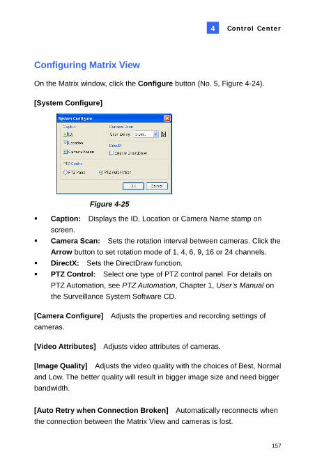
Control Center
157
4
32BConfiguring Matrix View
On the Matrix window, click the Configure button (No. 5, Figure 4-24). [System Configure]
Figure 4-25
Caption: Displays the ID, Location or Camera Name stamp on screen.
Camera Scan: Sets the rotation interval between cameras. Click the Arrow button to set rotation mode of 1, 4, 6, 9, 16 or 24 channels.
DirectX: Sets the DirectDraw function. PTZ Control: Select one type of PTZ control panel. For details on
PTZ Automation, see PTZ Automation, Chapter 1, User’s Manual on the Surveillance System Software CD.
[Camera Configure] Adjusts the properties and recording settings of cameras. [Video Attributes] Adjusts video attributes of cameras. [Image Quality] Adjusts the video quality with the choices of Best, Normal and Low. The better quality will result in bigger image size and need bigger bandwidth. [Auto Retry when Connection Broken] Automatically reconnects when the connection between the Matrix View and cameras is lost.

158
33BPOS Live View
The POS Live View allows you to view POS transaction data or cardholder information of access control in a separate window.
To open the POS Live View window, click the ViewLog button (No.6, Figure 4-24) and select POS Live View.
To have the instant playback, double-click the desired transaction item or cardholder data on the POS Live View window.
Figure 4-26
For details on POS Live View, see POS Live View, Chapter 3, User’s Manual on the Surveillance System Software CD.

Control Center
159
4
34BInstant Playback
When monitoring through Matrix View, you can instantly play back any suspicious videos of a certain time length. Time length choices include 10 seconds, 30 seconds, 1 minute and 5 minutes. For details see 4.14 Instant Playback.
To instantly play back the event(s) of one single channel, click on the Camera Name, and select the time length.
To instantly play back the events of all channels, click the ViewLog button (No.6, Figure 4-24), select Instant Play, and select the time length.
Also see [Matrix] in 4.5 System Configuration.

160
12B4.12 IP Matrix The IP Matrix is designed to reduce trips to set up remote monitors. The operator can remotely assign cameras to be displayed, set screen divisions, start camera scan and etc. This feature is useful for TV wall control. The IP Matrix allows the operator to monitor up to 36 Matrix views with 3840 ((96 x (36+4) =3840)) cameras in total over the network. The IP Matrix application is illustrated as below. For details on the Matrix view, see 4.11 Matrix View.
Matrix
One server connects the maximum of four (4) monitors, each monitor displays one (1) Matrix view, and one (1) Matrix view displays up to 96 cameras.
IP Matrix controls up to 36 Matrix views

Control Center
161
4
35BRunning IP Matrix
To run the IP Matrix, you have to set up both client servers and Control Center.
Note: An appropriate USB dongle is required for each client server.
On client servers:
1. Insert the CMS Software CD to the computer. It will run automatically. A window appears.
2. Select the Install V8.2.0.0 Central Monitoring System item. 3. Click IP Matrix, and follow the on-screen instructions. 4. After the computer is restarted, go to the Windows Start menu, point to
Programs, select IP Matrix and click IP Matrix. This dialog box appears.
Figure 4-27
5. Type the IP address of the Control Center, and modify the communication port if necessary.

162
6. Click Advance. This dialog box appears.
Figure 4-28 [Location Name] Names the client server. [Startup] Automatically connects to the Control Center when the program is started. [Monitor] This field displays the number, position coordinates and resolution of monitors that are connected to the client server. Enable the desired monitors for remote control.
7. Click OK and then Connect to build connection with the Control Center.
On Control Center:
1. Click the IP Matrix List icon on the Control Center toolbar. The IP Matrix window appears.
2. Click the right arrow button on top left corner to start the service. The icons of connected monitors will be displayed at the bottom of the window.
3. To display monitor views, drag and drop the monitor icons from the bottom to the desired squares on the IP Matrix.

Control Center
163
4
Figure 4-29 4. To assign cameras to be displayed on a specific monitor, drag a group
from the Group List and drop on the monitor square. Or, right-click the monitor square and select Set Channel to choose a group.
Drag and drop a group to the desired monitor for display.
Figure 4-30
5. To enlarge and manage one monitor view, double-click the monitor square and use the toolbar for control. For details on the toolbar, see The Controls on the Window below.
This field displays connected monitors.
Click the button to start service
Monitor square

164
36BThe Controls on the Window
1
4
3 5
6
7
8
9
10
2
Figure 4-31
No. Name Description 1 Start /
Stop Service Starts or stops the connection to client servers.
2 Show / Hide List
Opens or closes the monitor list at the bottom of the window.
3 Layout Setup Includes these settings: • Screen Division: Specify the screen division
of IP Matrix. The maximum number of divisions is 36, e.g. 9 x 4 or 4 x 9.

Control Center
165
4
• Screen update rate: Specify the update frequency for all camera views on the monitor square.
• Clear all set monitors’ position: Clears the IP Matrix view every time when you modify the screen division.
4 Set Channel Focus on one monitor view, click this icon, and select one group for display.
5 Matrix Configure Focus on one monitor view, click this icon, and set caption display, camera scan interval, DirectX and PTZ control method.
6 Start / Stop Scan Focus on one monitor view, click this icon, and select to start or stop the camera scan function.
7 Set Quad Focus on one monitor view, click this icon, and set the screen division.
8 Page Up & Page Down
Focus on one monitor view, and click one of these icons to scroll the page up and down.
9 Monitor Square Displays the monitor views. Right-click one monitor view to have these settings: • Set Channel: Select a group for display. • Advanced Control: Enlarges the monitor
view for further management. • Remove Monitor: Removes the monitor view
from the monitor square. 10 Monitor Icon The icons of connected monitors. Right-click one
icon to have the setting: • Identify Monitor: Displays a large number
on the monitor square, showing which monitor square corresponds with which monitor icon.
Also see [IP Matrix] in 4.5 System Configuration.

166
13B4.13 VMD Monitoring The Control Center provides the VMD (video motion detection) function. When motion is detected, the operator will be alerted with a pop-up display of the live video. Note: The VMD feature does not support the third-party IP cameras.
37BRunning VMD
1. Drag the desired cameras from the Host List and drop to VMD Group in the Group List.
2. To open the VMD window, click the VMD System icon. When motion is detected within the camera view, the live video will pop up on the VMD window.
Figure 4-32
VMD System

Control Center
167
4
38BThe Controls on the Window
1 3 45
6
7
2
Figure 4-33
No. Name Description 1 Page Up & Down Scrolls the page up and down. 2 Refresh Refreshes the camera view. The feature is
unavailable when the Popup camera by user-defined position option is enabled (see Figure 4-16).
3 Select Quad Sets the screen division. 4 Show System Menu Includes these settings:
• Image Quality: Select one of these qualities: Best, Normal and Low.
• Host List: Displays the host tree list.

168
• System Configure: Enable DirectX and specify the Post-Motion duration for the camera view remaining on the window after motion stops.
5 Minimize Minimizes the window in Windows taskbar. 6 Exit Closes the window. 7 Pop-up camera Right-click the pop-up camera to have these
settings: • Advanced Live View: Opens the live view
window for further control. • Instant Playback: See Instant Playback
below.
Also see [VMD System] in 4.5 System Configuration.

Control Center
169
4
14B4.14 Instant Playback
You can retrieve the recordings from the DVR or video server and play video back.
The following function must be enabled ahead to allow remote access from the Control Center: • DVR: Enable recording and Remote ViewLog Service on Control
Center Server.
• Video Server: Enable recording and the Remote ViewLog function.
The places to play video back:
• In the Group List, right-click one camera and select Instant Play.
• In the VMD window, right-click the pop-up camera and select Instant Play.
• In the Matrix view, click on the Camera Name and select Instant Play.
Figure 4-34

170
Right-click the Playback window to have the following features:
Name Functions
Play Mode
Includes these options: • Frame by Frame: Plays back video frame by
frame. • Real Time: Plays back video on real time. This
mode saves waiting time for rendering, but drop frames to give the appearance of real-time playback.
• Audio: Turns on or off the video sound.
Render
Includes these options: • Deinterlace: Converts the interlaced video into
non-interlaced video. • Scaling: Smoothens mosaic squares when
enlarging a playback video • Deblocking: Removes the block-like artifacts from
low-quality and highly compressed video. • Defog: Enhances image visibility. • Stabilizer: Reduces camera shake. • Text overlay’s camera name and time: Overlays
camera name and time onto the video. • Text overlay’s POS/GV-Wiegand: Overlays POS
or GV-Wiegand Capture data onto the video. • Full Screen: Switches to the full screen view.
Tools
• Snapshot: Saves a video image. • Save as AVI: Saves a video as avi format. • Download: Downloads the video clip from the
DVR or video server to the local computer.

Control Center
171
4
15B4.15 PIP and PAP View With PIP (Picture in Picture), you can crop your video to get a close-up view or zoom in on your video. With PAP (Picture and Picture), you can create a split video effect with multiple close-up views on the video. You can enable PIP or PAP functions in Live View, Remote ViewLog and Matrix View. • Live View: In the Group List, right-click one camera and select Live
View. In the Live View window, click the Change Size icon and select PIP View or PAP View.
Figure 4-35
• Playback: Right-click one camera in the Host List or the Group List, and select Remote ViewLog. In the Remote ViewLog window, click the View Mode button, select Single View, and select Mega Pixel (PIP) or Mega Pixel (PAP).
• Matrix: Right-click one camera view, and select PIP View or PAP View.
For details on using PIP and PAP, see Picture-in-Picture View and Picture-and-Picture View, Chapter 1, User’s Manual on the Surveillance System Software CD.

172
4.16 16BPanorama View Spliced from multiple camera images, a panorama view provides a continuous scene for live monitoring. Each camera selected for the panorama view will keep the recording in original format. Up to 4 sets of panorama views can be created. Note: This function is only available when an appropriate USB dongle is used. To access this feature, on the Group List, right-click the desired group, and select Panorama Setting. The CMS Panorama program is enabled and minimized to the system tray. The Panorama Setup dialog box also appears. For the controls on the dialog box, see Panorama View, Chapter 1, User’s Manual on the Surveillance System Software CD.
39BCreating a Panorama View
To create a panorama view, see the same topic in Panorama View, Chapter 1, User’s Manual on the Surveillance System Software CD.
40BAccessing a Panorama View
There are two ways to access a panorama view:
• Right-click the Group that has set a Panorama view, select Panorama View and select the desire panorama set from the list.
• Right-click the CMS Panorama icon on the system tray, select Panorama View, and select the desired panorama set from the list.
41BPanorama View Controls
To control a panorama view, see to the same topic in see Panorama View, Chapter 1, User’s Manual on the Surveillance System Software CD.

Control Center
173
4
17B4.17 I/O Central Panel The I/O Central Panel provides a centrally managing solution for I/O devices from different DVRs. Its major features are: • Group I/O devices from different DVRs • Trigger I/O devices in cascade mode • Monitor different I/O cascade configurations at different times of the
day • Quick access triggered I/O devices by a Quick Link window Note:
• The Advanced I/O Panel at the client DVR and the I/O Central Panel at the Control Center can conflict each other. It’s recommended that the client DVR cleans up the settings in the Advanced I/O Panel and renders the I/O control to the Control Center.
• The I/O Central Panel does not support the third-party IP cameras and video servers.
42BRunning the I/O Central Panel
1. The client DVR must activate Control Center Service (No. 2, Figure 4-17) first.
2. Click the I/O Central Panel on the Control Center toolbar. When the connection is established, the I/O Central Panel will display on the Control Center desktop.

174
43BThe I/O Central Panel
Figure 4-36
The controls on the I/O Central Panel:
No. Name Description 1 Configure Accesses Panel and Schedule settings. 2 Mode Schedule Starts/stops Mode Schedule. 3 Toggle Quick Link Displays the Quick Link window for quick access
to triggered I/O devices. 4 Advanced I/O List Style Displays the Advanced I/O List in various styles:
View/Edit, Icon and Detail. 5 Expand Tree Row Expands tree branches. 6 Collapse Tree Row Collapses tree branches. 7 Mode Configures various cascade modes. 8 Standard I/O List Displays connected I/O modules. 9 Advanced I/O List Groups I/O devices in cascade mode.

Control Center
175
4
44BCreating a Group for Cascade Triggers
You can group I/O devices by function or geography. Further, the group allows cascade triggers, meaning that the trigger actions of one trigger can activate another trigger. For this example, you might have a group called “Entrance” that contains all I/O devices installed at entrances. The “Entrance” group might contain other sub groups, each of which contains just the related I/O devices in various geographic locations:
Group containing all I/O devices installed at entrancesInput 2 installed at the front entranceOutput 1 sub group at the kitchen
Output 3 sub group at the garage Figure 4-37
When Input 2 is triggered, it will trigger Output 1 and Output 3 sub groups, and Output 1 will trigger Output 2 in a cascade series.

176
Creating a Group:
1. Right-click on Advanced I/O List, and then select Add A Group. This dialog box appears.
Figure 4-38 [Group Name] Names the group. [Group Notify Setting] Invoke Alarm: Invokes the computer alarm on I/O trigger.
Select a sound from the drop-down list. 2. Click Save to apply the settings, and return to the panel. 3. To create a cascading hierarchy, drag the desired inputs/outputs from
the left Standard I/O List to the group. Note: In the cascading hierarchy, each input can only be used once while the same output can be used repeatedly.

Control Center
177
4
Editing a Group:
To modify group settings, right-click a group, and select View/Edit. This dialog box appears.
Figure 4-39
[Group Name] As described in Figure 4-38. [Group Notify Setting] As described in Figure 4-38.

178
[Current Pin Setting] To enable this option, highlight an I/O device from the group list at the bottom. Trigger Associated Outputs: Triggers outputs in cascade mode.
Click the Finger tab to apply the change to all I/O devices at the same group.
Change Icon: To enable this option, select one of two displayed icons: Normal or Trigger. Click the Change Icon tab to change an icon. Click the Finger tab to apply the change to all I/O devices at the same group.
Editing an I/O Device:
In addition to editing groups, you can also edit the settings of individual I/O device. Right-click an I/O device, and select Setting. This dialog box appears.
Figure 4-40
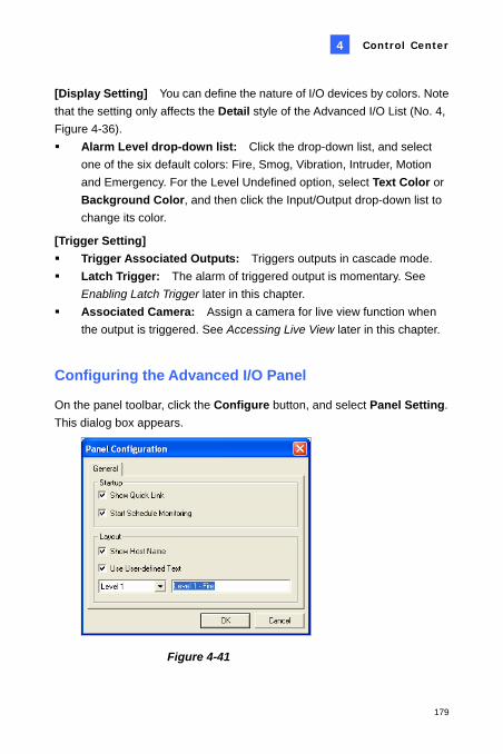
Control Center
179
4
[Display Setting] You can define the nature of I/O devices by colors. Note that the setting only affects the Detail style of the Advanced I/O List (No. 4, Figure 4-36). Alarm Level drop-down list: Click the drop-down list, and select
one of the six default colors: Fire, Smog, Vibration, Intruder, Motion and Emergency. For the Level Undefined option, select Text Color or Background Color, and then click the Input/Output drop-down list to change its color.
[Trigger Setting] Trigger Associated Outputs: Triggers outputs in cascade mode. Latch Trigger: The alarm of triggered output is momentary. See
Enabling Latch Trigger later in this chapter. Associated Camera: Assign a camera for live view function when
the output is triggered. See Accessing Live View later in this chapter.
45BConfiguring the Advanced I/O Panel
On the panel toolbar, click the Configure button, and select Panel Setting. This dialog box appears.
Figure 4-41

180
[Startup] Show Quick Link: Opens the Quick Link window at panel startup. Start Schedule Monitoring: Starts Mode Schedule at panel startup.
For details, see Setting up Mode Schedule below.
[Layout]
Show Host Name: Displays the host name of each I/O device on the Advanced I/O List.
Use User-defined Text: Allows you to modify the text of Alarm Level (see Figure 4-40).
46BSetting Up Mode Schedule
The Mode Schedule allows you to monitor different I/O cascade configurations at different time. For example, you may want I/O cascade triggers one way during business hours and another way for non-business hours. Modes can be switched automatically at a scheduled time.
Creating a Mode:
1. Click the Mode drop-down list (No. 7, Figure 4-36), and select More Edit. This dialog box appears.
Figure 4-42

Control Center
181
4
2. Click Add, and name the created mode. You can create up to 100 modes.
3. Click Save to return to the panel. 4. Select the created mode from the Mode drop-down list, and create the
groups in the Advanced I/O List. For details, see Creating a Group for Cascade Triggers earlier in this chapter.
Creating a Mode Schedule:
Define the times and days you like the panel to switch modes.
1. On the panel toolbar, click the Configure button, and select Schedule
Setting. This dialog box appears.
Figure 4-43

182
2. Click Add to create a schedule. This dialog box appears.
Figure 4-44
Name: Type a name for the schedule. Mode: Select a mode from the drop-down list. Time: Define a time period you want the mode to run. Days: Check the day box(es) you want the mode to run.
3. Click OK to apply the settings, and click Save to return to the panel. 4. To start the mode schedule, click the Mode Schedule button (No. 2,
Figure 4-36), and then select Mode Schedule Start.
47BQuick Link
The Quick Link provides a quick access to triggered I/O devices. It is a separate window to display all group icons. The group icon flashes when any included I/O device is triggered. Clicking the flashing icon will bring you to the I/O location in the Advanced I/O List.
To open the Quick Link window, click the Toggle Quick Link button. (No. 3, Figure 4-36).
To open the Quick Link window at panel startup, check the Show Quick Link option in Figure 4-41.
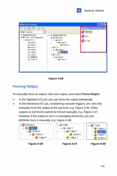
Control Center
183
4
Figure 4-45
48BForcing Output
To manually force an output, click one output, and select Force Output.
In the Standard I/O List, you can force the output individually. In the Advanced I/O List, considering cascade triggers, you can only
manually force the output at the top level, e.g. Figure 4-46. Other outputs at sub levels cannot be forced manually, e.g. Figure 4-47. However, if the output is not in a cascading hierarchy, you can definitely force it manually, e.g. Figure 4-48.
Figure 4-46 Figure 4-47 Figure 4-48

184
49BEditing Background Image
With the Background Image feature, you can import a floor plan to lay out the locations of triggered I/O devices. This feature works in the Icon style of the Advanced I/O List. 1. To switch to the Icon style, click the Advanced I/O List Style button
(No. 4, Figure 4-36) and then select Icon. 2. Select a group in the Advanced I/O List. The I/O icons of this group will
be displayed. 3. Right-click on the right screen, and select Background Image to
import a graphic file. 4. Right-click on the right screen, and uncheck Auto Arrange. Now you
can freely drag the I/O icons to the desired locations on the imported map.
5. To add images to another group, repeat the steps 2 to 4.
Note: Highlighting Advanced I/O List in the Advanced I/O List, you can import another image.
Figure 4-49

Control Center
185
4
50BManaging a Group of I/O Devices
With groups of I/O devices set up on the I/O Advanced Panel, you can enable or disable these I/O devices by groups.
Enabling a Group On the I/O Advanced Panel, right-click a desired group and select Start Monitoring. All input devices of this group are now enabled. When inputs are triggered, outputs will be activated in cascade mode. Disabling a Group On the I/O Advanced Panel, right-click a desired group and select Stop Monitoring. All input devices of this group are now disabled. No cascade triggers will occur. Pausing the Triggered Inputs This feature is designed for a group of outputs set to be Toggle mode. When inputs activate outputs in cascade triggers, right-click this group and select Pause Monitoring. The inputs of the group will be reset, but the outputs keep on alarming.

186
51BArming/Disarming I/O Devices
The Control Center operator can manually arm or disarm any I/O devices of client DVRs without interrupting the monitoring.
Arming or disarming I/O devices
1. On the Standard I/O List, right-click one host and select I/O Enable Setting. This dialog box appears.
Figure 4-50 2. Check the Input/Output to arm or uncheck the Input/Output to disarm
the device (s). Then click Apply to verify the changes.
52BEnabling Latch Trigger
Instead of a lasting output alarm, the Latch Trigger option provides a momentary alarm when an input is triggered in cascade mode. For details, see Latch Trigger, Chapter 2, User’s Manual on the Surveillance System Software CD. 1. Right-click one input on the Advanced Group List, and select Setting.

Control Center
187
4
2. In the dialog box, enable the Latch Trigger option.
Figure 4-51
53BAccessing Live View
You can access live view by assigning one camera to the input device. 1. On the Advanced Group List, right-click one input and select Setting. 2. In the dialog box (Figure 4-51), enable the Associated Camera option,
and then assign a camera from the drop-down list. 3. Click OK to save the settings. 4. To view live video, click that input on the panel, and then select View
Associated Camera.
54BVirtual I/O Support
If client DVRs enable the Virtual I/O function to control the I/O devices connected to GV-Video Server and GV-Wiegand Capture, the Control Center can also control these added I/O devices during the connection. For details about Virtual I/O, see Virtual I/O Control, User’s Manual on the Surveillance System Software CD.

188
4.18 18BRemote E-Map The Control Center can create E-Maps for client DVRs to monitor the surveillance sites on an electronic map. 1. First create E-Maps for client DVRs.
Click the Configure button (No. 2, Figure 4-2) on the Edit toolbar and then select E-Map Editor. Or,
Select E-Map Editor within the Control Center folder from the Windows Start menu.
For details on creating an E-Map, see Creating an E-Map File, Chapter 7, User’s Manual on the Surveillance System Software CD.
2. On the Host List, click the Remote E-Map button to connect to the DVRs. Once the connection is established, the Remote E-Map will appear on the Control Center desktop.
Figure 4-52

Control Center
189
4
19B4.19 Changing Interface Style The startup of Control Center is in a toolbar format and the operator may open a variety of windows to manage client hosts, such as Host List, Group List, Live View, Playback and IP Matrix. Now the operator may choose to open all these managing windows in one screen.
To change the user interface:
1. Click the Configure button and select System Configure. This dialog box appears.
Figure 4-53
2. To change user interface, click the Control Center Style drop-down list and select one of these options:
Advanced Style: the toolbar format. Standard Style: the window format.
3. Click OK and restart the Control Center for the new style to take effect.

190
55BThe Standard Window
You can move freely any managing windows and resize them.
Figure 4-54
20B4.20 Controlling the PTZ Using GV-Joystick You can control the PTZ cameras using up to 4 GV-Joystick in Live View and Matrix. You need to run the following program in the background when using the GV-Joystick to control PTZ.
For details, see 1.21 Controlling the PTZ Cameras Using GV-Joystick
Drag and drop any camera from Host List to this Live View window.

Control Center
191
4
21B4.21 Specifications
Feature Amount Note DVR Host 1000 Hosts Video Server Host IP Camera Host
Compact DVR Host 500 Hosts
The total number of Video Server, IP Camera, Compact DVR hosts is 500.
Remote DVR Unlimited Remote Desktop Unlimited Remote ViewLog 1 One at a time.
I/O Host
• DVR: 1000 Hosts • GV-Video Server +
GV-IP Camera + GV-Compact DVR: 500 CH
• Only for GV IP products.• One host supports up to
9 sets of 16-in and 16-out I/O modules.
Remote E-Map Host 500 Hosts Remote E-Map Map Unlimited Live View (Advanced Type UI)
1 One at a time from one application.
Live View Channel (Standard Type UI)
20 CH
Matrix 4 Matrix Views Matrix Group Unlimited
Matrix Channel 384 CH For 1920x1200, 1920x1080 resolution.
IP Matrix 36 Monitors IP Matrix Channel 3840 CH VMD Group 1

192
VMD Group Channel
• DVR: 1000 CH • GV-Video Server +
GV-Compact DVR + GV-IP Camera: 200 CH
Only for GV IP products
Panorama View 4 Views Panorama Channel 16 CH Matrix 1024x768: 64 CH Total: 256 CH on 4 Matrix. 1280x1024: 64 CH Total: 256 CH on 4 Matrix.
1680x1050: 80 CH Total: 320 CH on 4 Matrix. 1600x1200: 64 CH Total: 256 CH on 4 Matrix. 1920x1200: 96 CH Total 384 CH on 4 Matrix. 1920x1080: 96 CH Total 384 CH on 4 Matrix. 1280x800: 64 CH Total 256 CH on 4 Matrix. 1440x900: 64 CH Total 256 CH on 4 Matrix.
Product specifications are subject to change without notice.