gvf rough terrain forklift gillison’s variety fabrication ... · gvf rough terrain forklift parts...
TRANSCRIPT
GVF Rough Terrain Forklift
Parts ManualModel Number:
GVF 5000
Manual Part Number: GL 11485
GVF
3033 Benzie Hwy. Benzonia, Mi 49616 231-882-5921Fax 231-882-5637 800-392-6059
Gillison’s Variety Fabrication, Inc.
email: [email protected] online: www.gillisons.com
Table of Contents
TABLE OF CONTENTS
INTRODUCTION 1
ENGINE ACCESSORIES 2
AIR INTAKE 2
Intake Tube 4
Tier II Air Cleaner 2
Tier III Air Cleaner 3
COOLING SYSTEM 5
Lower Radiator Hose Tee 7
Radiator Fan Shroud 6
Radiator Hoses 8
ELECTRICAL 9
Additional Electrical Components 18
Alternator 13
Control Lever Connections 13
FNR Switch Wire Harness 16
Harness 15
Main Wiring 15
Plug Kits 11
Relay, Start 14
Shift Knob Assenbly 12
Terminals & Housings 9
Work Lights Harness 17
EXHAUST 19
Exhaust 20
Exhaust 21
Exhaust Hanger 22
FILTERS 23
THROTTLE 24
Throttle Components 24
FRAME AND SHEET METAL 25
BATTERY BOX 25
CHASSIS FRAME 26
Main Chassis Frame Chart 27
Main Chassis Frame Diagram 26
DECALS 28
Forklift Decal Set 29
FIRE WALL 30
Firewall Diagram and Chart 30
FALLING OBJECT PROTECTION SYSTEM 31
FOPS Diagram and Chart 31
FUEL TANK 32
Fuel Tank Diagram and Chart 32
HOOD 33
Hood Diagram and Chart 33
Hood Hinge Diagram and Chart 34
OPERATOR’S PLATFORM 35
Operator’s Platform Components 35
PAINT 37
WEIGHT BOX 38
HYDRAULIC SYSTEM 39
CONTROL VALVE, 39
Handle With Ball Knob 43
Inlet Section 40
Lift Valve Section 40
Outlet Section 41
Valve Pivot Assembly 42
Work Section 41
CYLINDERS 44
Hydraulic Oil Tank 1 47
Hydraulic Oil Tank 2 48
Master Cylinder 45
Remote Actuator 46
Tilt Cylinder 44
PUMP 49
Hydraulic Pump 50
Hydraulic Pump Control Cover 49
MATERIAL HANDLING SYSTEM 51
BIN CLAMP 51
Bin Clamp Cylinder 52
FORKS 53
Drilling Holes in Fork Blades 59
Fork Inspection Guidelines 55
Fork Inspection Log 53
Fork Maintenance and Inspection 56
Forks 58
MAST 60
6 Roller Carriages 71
2600 PSI Main Lift Cylinders Chart 62
2600 PSI Main Lift Cylinders Diagram 61
Common Parts 65
Common Parts 67
Common Parts, 48” Integral Carriage 64
Hoist Chains 68
Hydraulic Group 69
Inner Weldment Diagram 66
Internal Hose Reeving Chart 73
Internal Hose Reeving Diagram 72
Introduction to Mast Section 60
Load Backrest 70
Lowering Control Valve 70
Outer Weldment Diagram 63
SIDESHIFTER - F SERIES 74
Base Unit 75
Cylinder Assembly 76
Introduction to Sideshifter Section 74
BACK REST 76
POWERTRAIN 77
Brakes 462/20880 Diagram 79
Drivehead 461/22790 Diagram 82
Front Axle Diagram 77
Hub Components 461/22790 Diagram 84
Parking Brake 462/20880 Diagram 80
PD70 Drivehead Diagram 78
Rear Axle SD55 Diagram 81
Steer Knuckle 461/22790 Diagram 83
BRAKES 85
Brake Cable 86
Parking Brake 85
DRIVESHAFT 87
Front Drive Shaft 87
Rear Driveshaft 88
U-Joint 1410 Series 88
U-Joint 1480 Series 87
U-Joint 1480 Series 88
TIRES 89
TRANSMISSION 90
SS700 4WD, 460/60050 Diagram 90
SS700 4WD, 460/60050 Diagram 93
SS700 4WD, Clutch Unit Diagram 94
SS700 4WD, Gear Change Diagram 91
SS700 4WD, Internal Components Diagram 95
SS700 4WD, Pump & Main Hyd Pump Drive Dia-gram 96
Table of Contents
SS700 4WD, Reverser Unit Diagram 92
WHEEL ASSEMBLY 97
STEERING 98
STEERING COLUMN 98
STEERING CYLINDER 99
STEERING CYLINDER DIAGRAM 100
STEERING MOTOR 101
STEERING MOTOR PARTS BREAKDOWN 102
Table of Contents
8/1/18
GVF Rough Terrain Forklift Parts Manual INTRODUCTION 1
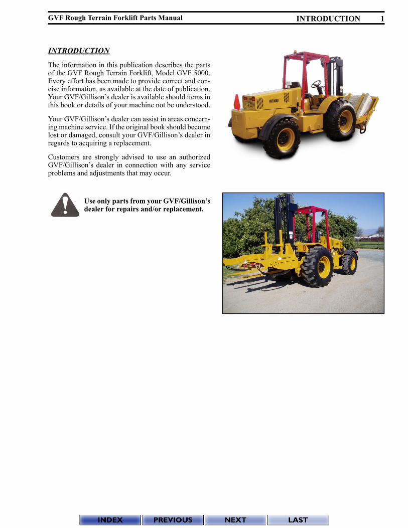
INTRODUCTION
The information in this publication describes the parts of the GVF Rough Terrain Forklift, Model GVF 5000. Every effort has been made to provide correct and con-cise information, as available at the date of publication. Your GVF/Gillison’s dealer is available should items in this book or details of your machine not be understood.
Your GVF/Gillison’s dealer can assist in areas concern-ing machine service. If the original book should become lost or damaged, consult your GVF/Gillison’s dealer in regards to acquiring a replacement.
Customers are strongly advised to use an authorized GVF/Gillison’s dealer in connection with any service problems and adjustments that may occur.
Use only parts from your GVF/Gillison’s dealer for repairs and/or replacement.
8/1/18
2 ENGINE ACCESSORIES - Air Intake GVF Rough Terrain Forklift Parts Manual
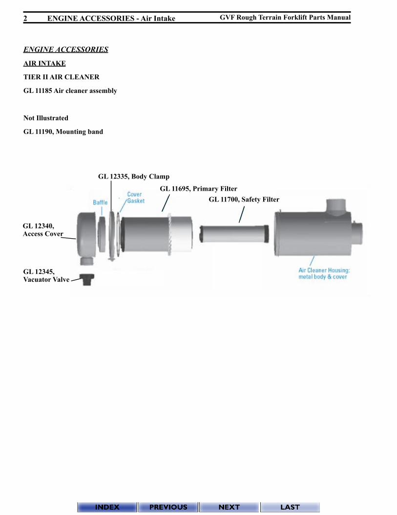
ENGINE ACCESSORIES
AIR INTAKE
TIER II AIR CLEANER
GL 11185 Air cleaner assembly
Not Illustrated
GL 11190, Mounting band
GL 12335, Body Clamp
GL 12340, Access Cover
GL 12345, Vacuator Valve
GL 11695, Primary FilterGL 11700, Safety Filter

3ENGINE ACCESSORIES - Air IntakeGVF Rough Terrain Forklift Parts Manual
TIER III AIR CLEANER
GL 12260 Air cleaner assembly
10 • Engine Air Cleaners, Accessories & Service Parts
Pow
erCo
re®
Air
Cle
aner
s
PSD Air Cleaner
www.donaldson.com/aircleaners
Millions of PowerCore® Filters Installed on Original Equipment!Three times more efficient than average conventional pleated paper filters
This new air cleaner family offers two-stage filtration in a single, compact unit that delivers superior filtration performance using our PowerCore® Filtration Technology.
This non-metal air cleaner (except for cover clamps) is ideal for medium- and heavy-duty equipment operating in light to medium dust environments.
When you request PowerCore Filtration Technology, you will gain...Equal or better performance in a small package – the freedom to design unique configurations to fit tight spots and overall design simplicity.
Donaldson reliability - backed by nearly a century of innovation and experience. Donaldson supplies air filtration products to almost every vehicle manufacturer.
Lower shipping and inventory costs – PowerCore filters are lighter and take up less shelf space.
Primary filter with PowerCore Filtration Technology
Cover retention latches
Safety filter (included)
Injection molded body
Filter service indicator port
Pre-cleaner drop tubeHousing comes with a Vacuator™ Valve (P158914). Drop tube designed to be used as a scavenge line or with a Vacuator Valve.
High efficiency pre-cleaner tubes
Integratedmounting brackets
Primary filter with PowerCore Filtration Technology
Cover retention latches
Safety filter service handleincluded
Injection molded body Available in standard or long lengths (Inlet/outlet ends are permanently secured to this piece - shorter length shown)
Filter service indicator port
Pre-cleaner drop tubeDesigned to be used as a scavenge line or with a Vacuator™ Valve. Models available with tube on long side of inlet.
High efficiency pre-cleaner tubes
Vacuator ™ Valve
Integrated mounting bracketson three sides of the body
Removable access cover
Service handle attached to filter
Attachment pointsfor your inlet ducting accessories
Service Access on Inlet End - PSD08
Service Access on Side - PSD09, PSD10 and PSD12
Exploded view is of D080020. For tube on long side of inlet end (opposite clamps), consider D080026.
Exploded view is of D090019 model. For tube on long side of inlet end, consider D090020 or D090022.
Donaldson PowerCore® products are protected internationally by patents, trademarks, and design registrations, both issued and pending.
GL P776033 GL P601735
GL 12270
- cover
GL P12290Indicator, air filter restriction
O 1409 CLAMP,T BOLT TBC 400
OP 101290 ADAPTER,3 1/2” - 3”
O 1415 CLAMP,T BOLT TBC 350
GL 12275 TUBE,AIR INTAKE TIER III
O 1414 CLAMP,T BOLT TBC 300
OP 102820 ADAPTER,3” - 2 1/2”
O 1415 CLAMP,T BOLT TBC 350
AIR INTAKE
GL 12265
4 ENGINE ACCESSORIES - Air Intake GVF Rough Terrain Forklift Parts Manual1 1
2 2
3 3
4 4
AA
BB
CC
DD
SHEE
T 1
OF
1
DR
AWN
CHEC
KED
QA
MFG
APPR
OVE
D
Mat
t9/
13/2
006
DW
G N
O
GL9
5301
TITL
E
INTA
KE T
UBE
SIZE C
SCAL
E
GIL
LISO
N'S
VAR
IETY
FAB
.
REV
Part
s Li
stD
ESCR
IPTI
ON
PART
NU
MBE
RQ
TYIT
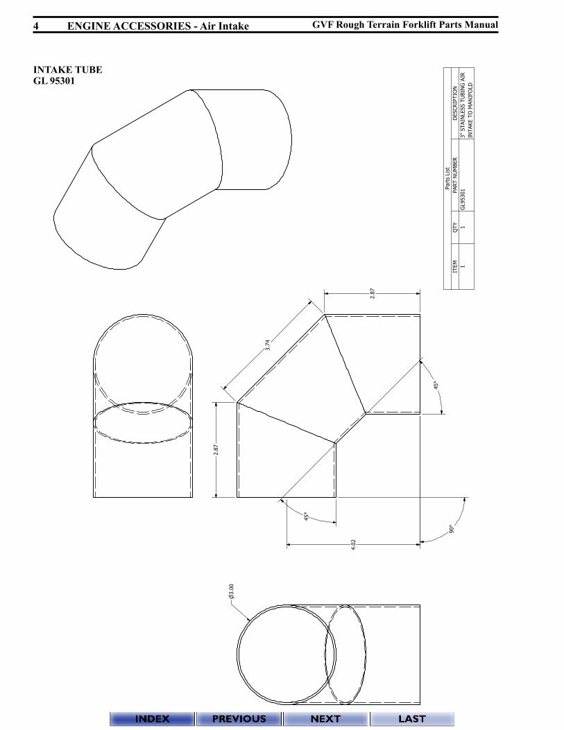
EM3"
STA
INLE
SS T
UBI
NG
AIR
IN
TAKE
TO
MAN
IFO
LDG
L953
011
1
2.87
3.74
2.87
45°
45°
90°
n3.
00
4.02
INTAKE TUBEGL 95301
ENGINE ACCESSORIES - Cooling System 5GVF Rough Terrain Forklift Parts Manual
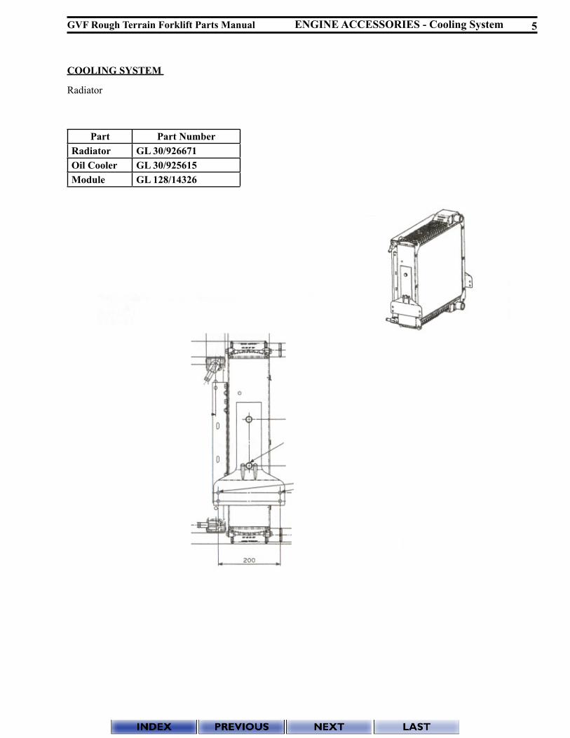
COOLING SYSTEM
Radiator
Part Part NumberRadiator GL 30/926671Oil Cooler GL 30/925615Module GL 128/14326

ENGINE ACCESSORIES - Cooling System6 GVF Rough Terrain Forklift Parts Manual
RADIATOR FAN SHROUD
Reference: Used on forklifts with serial numbers GL 2000 through current.
1 1
2 2
3 3
4 4
AA
BB
CC
DD
SHEE
T 1
OF
1
DR
AWN
CHEC
KED
QA
MFG
APPR
OVE
D
mat
t9/
11/2
008
DW
G N
O
GL9
5101
P
TITL
E
ENG
INE
FAN
SH
ROU
D
SIZE C
SCAL
E
GIL
LISO
N'S
VAR
IETY
FAB
.
REV
Part
s Li
stD
ESCR
IPTI
ON
PART
NU
MBE
RQ
TYIT
EMFA
N S
HR
OU
DG
L951
011
18M
M L
OCK
WAS
HER
N32
606
2H
HCS
8M
M -
1.25
X 1
6MM
G
R 8
.8N
3268
63
2 3
1
REV
ISIO
N H
ISTO
RYZO
NE
REV
DES
CRIP
TIO
ND
ATE
APPR
OVE
D
11
USE
D
GL2
000-
CUR
REN
T9/
11/2
008
mat
t
ENGINE ACCESSORIES - Cooling System 7GVF Rough Terrain Forklift Parts Manual
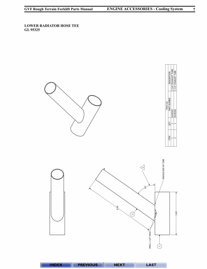
LOWER RADIATOR HOSE TEEGL 95325
1 1
2 2
3 3
4 4
AA
BB
CC
DD
SHEE
T 1
OF
1
DR
AWN
CHEC
KED
QA
MFG
APPR
OVE
D
Mat
t3/
20/2
007
DW
G N
O
GL9
5325
TITL
E
LOW
ER R
ADIA
TOR
HO
SE T
EE
SIZE C
SCAL
E
GIL
LISO
N'S
VAR
IETY
FAB
.
REV
Part
s Li
stD
ESCR
IPTI
ON
PART
NU
MBE
RQ
TYIT
EM1
3/4"
EXA
UST
TU
BEG
L953
251
11
1/2"
EXH
AUST
TU
BEG
L953
261
25.
00
55°
8.50
1
2
CRIM
P EN
D T
O 1
.390
WIT
H 1
35 D
IES
SET
TO 8
.54
DR
ILL
1 1/
4" H
OLE
RAD
IUS
END
OF
TUBE
REVI
SIO
N H
ISTO
RY
ZON
ER
EVD
ESCR
IPTI
ON
DAT
EAP
PRO
VED
11
CHAN
GED
ANG
LE W
AS 3
5°IN
CORR
ECT
11/8
/200
7M
att
1
EX
HA
US
T TU
BE
ENGINE ACCESSORIES - Cooling System8 GVF Rough Terrain Forklift Parts Manual
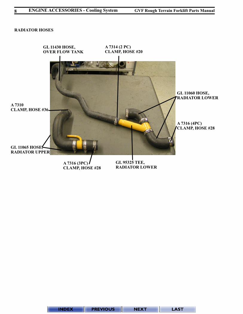
RADIATOR HOSES
GL 11065 HOSE, RADIATOR UPPER
A 7310CLAMP, HOSE #36
A 7316 (3PC)CLAMP, HOSE #28
GL 11060 HOSE,RADIATOR LOWER
GL 95325 TEE,RADIATOR LOWER
GL 11430 HOSE, OVER FLOW TANK
A 7314 (2 PC)CLAMP, HOSE #20
A 7316 (4PC)CLAMP, HOSE #28
ENGINE ACCESSORIES - Electrical 9GVF Rough Terrain Forklift Parts Manual
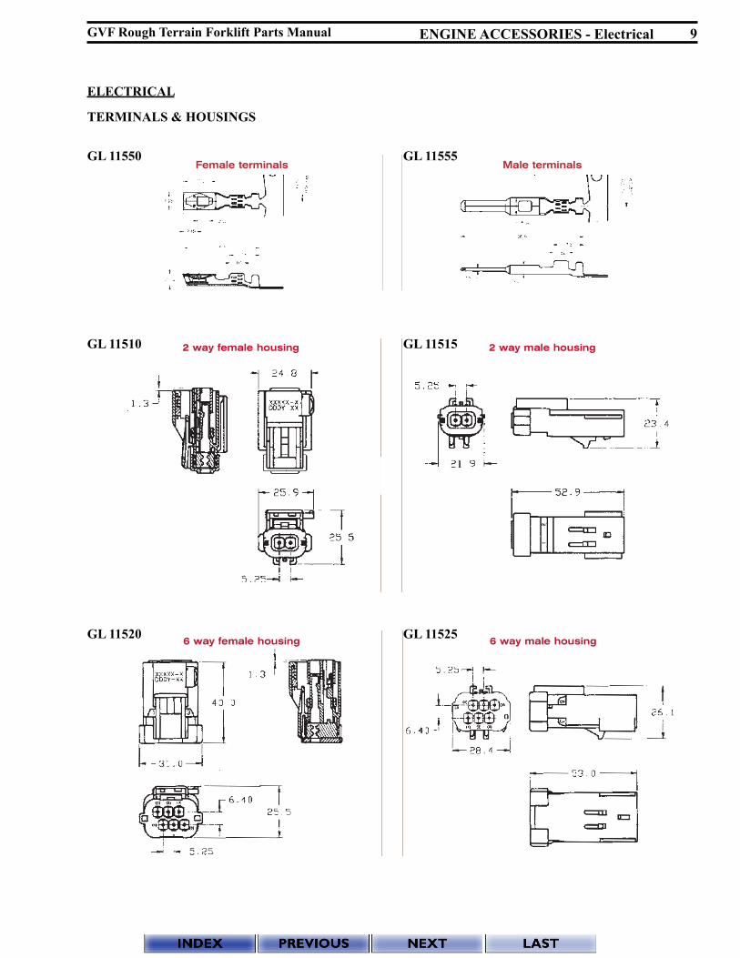
ELECTRICAL
TERMINALS & HOUSINGS
2 way female housing 2 way male housing
Coupling connectorsApex
6.20
Engine Compartment Connectors
Part Numbers No. of position Terminal size Type Colour
54200608 6 2.8 mm Female housing Black
54200609 6 2.8 mm Female housing Light grey
54200610 6 2.8 mm Female housing Dark grey
54200611 6 2.8 mm Female housing Natural
54200612 6 2.8 mm Male housing Black
54200613 6 2.8 mm Male housing Light grey
54200614 6 2.8 mm Male housing Dark grey
54200615 6 2.8 mm Male housing Natural
54201009 10 2.8 mm Female housing Black
54201010 10 2.8 mm Female housing Light grey
54201011 10 2.8 mm Female housing Dark grey
54201012 10 2.8 mm Female housing Light green
54201013 10 2.8 mm Female housing Dark green
54201014 10 2.8 mm Female housing Orange
54201015 10 2.8 mm Female housing Aqua
54201016 10 2.8 mm Male housing Black
54201017 10 2.8 mm Male housing Light grey
54201018 10 2.8 mm Male housing Light green
54201411 14 2.8 mm Female housing Black
54201412 14 2.8 mm Female housing Light grey
54201413 14 2.8 mm Female housing Dark grey
54201414 14 2.8 mm Female housing Natural
54201415 14 2.8 mm Male housing Black
54201416 14 2.8 mm Male housing Light grey
54201417 14 2.8 mm Male housing Dark grey
54201418 14 2.8 mm Male housing Natural
Dimensional characteristics
2/3/4/6/10/14 way sealed coupling housings for 2.8 mm terminals
Engine Compartment Connectors
Coupling connectorsApex
6.21
Dimensional characteristics
3 way female housing 3 way male housing
4 way female housing 4 way male housing
6 way female housing 6 way male housing
2/3/4/6/10/14 way sealed coupling housings for 2.8 mm terminals
Terminal Systems
Apex
1.26
Part Numbers Type Wire size range Insulation Ø Grease Material Plating(in AWG) (in mm)
Min. Max. Max.
54002208 (SWS) Female 22 22 1.75 No CuTeSn/CuBe Sn
54001807 (SWS) Female 20 18 2.13 No CuTeSn/CuBe Sn
54001404 (SWS) Female 16 14 2.77 No CuTeSn/CuBe Sn
54001202 (SWS) Female 12 12 3.35 No CuTeSn/CuBe Sn
54001008 (SWS) Female 12 10 4.09 No CuTeSn/CuBe Sn
54002209 (SWS) Female 22 22 1.75 Yes CuTeSn/CuBe Sn
54001810 (SWS) Female 20 18 2.13 Yes CuTeSn/CuBe Sn
54001409 (SWS) Female 16 14 2.77 Yes CuTeSn/CuBe Sn
54001205 (SWS) Female 12 12 3.35 Yes CuTeSn/CuBe Sn
54001009 (SWS) Female 12 10 4.09 Yes CuTeSn/CuBe Sn
54002210 (SWS) Female 22 22 1.75 No CuTeSn/CuBe Au
54001811 (SWS) Female 20 18 2.13 No CuTeSn/CuBe Au
54001410 (SWS) Female 16 14 2.77 No CuTeSn/CuBe Au
54001206 (SWS) Female 12 12 3.35 No CuTeSn/CuBe Au
54001010 (SWS) Female 12 10 4.09 No CuTeSn/CuBe Au
54002201 Male 22 12 1.75 - CuTeSn Sn
54001801 Male 20 18 2.13 - CuTeSn Sn
54001301 Male 20+20 18+18 - - CuTeSn Sn
54001401 Male 16 14 2.77 - CuTeSn Sn
54001001 Male 12 10 4.09 - CuTeSn Sn
54001804 Male 20 18 2.13 - CuTeSn PdAuNi
54002230 Male 22 22 1.75 - CuTeSn PdAuNi
54001818 Male 20 18 2.13 - CuTeSn PdAuNi
54002229 Male 22 22 1.75 - CuTeSn Au
54001819 Male 20 18 2.13 - CuTeSn Au
54002228 Male 22 22 1.75 - CuTeSn PdAuNi
Dimensional characteristics
Female terminals Male terminals
SWS: Single Wire Seal
2.8 mm female and male terminals
GL 11550
GL 11510
GL 11520
GL 11555
GL 11515
GL 11525
ENGINE ACCESSORIES - Electrical10 GVF Rough Terrain Forklift Parts Manual
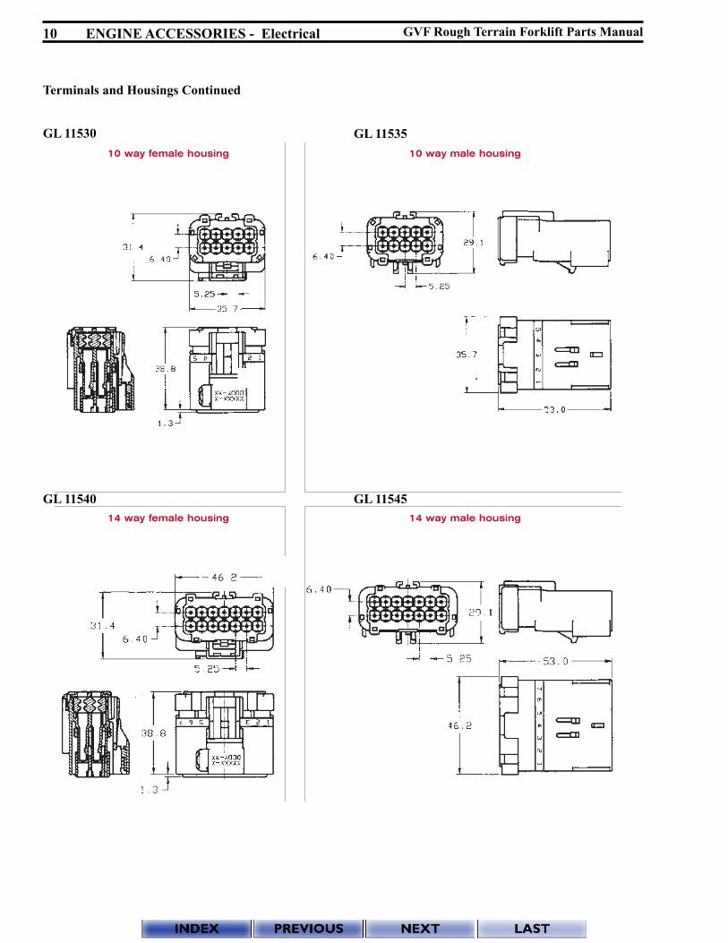
Terminals and Housings Continued
Coupling connectorsApex
6.22
Engine Compartment Connectors
Dimensional characteristics
10 way female housing 10 way male housing
14 way female housing 14 way male housing
2/3/4/6/10/14 way sealed coupling housings for 2.8 mm terminals
GL 11530
GL 11540
GL 11535
GL 11545
ENGINE ACCESSORIES - Electrical 11GVF Rough Terrain Forklift Parts Manual
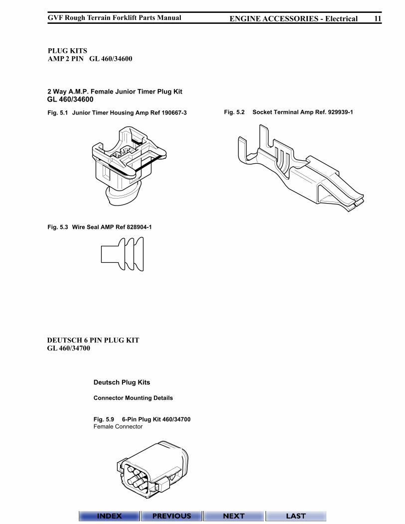
PLUG KITSAMP 2 PIN GL 460/34600
DEUTSCH 6 PIN PLUG KITGL 460/34700
5.8 9804/1207.1
Electrical & Electronic Systems
ITL Product Reference Manual
Electrical Wiring
Plug Kits (cont’d)
Deutsch Plug Kits
Connector Mounting Details
Fig. 5.9 6-Pin Plug Kit 460/34700Female Connector
Fig. 5.11 12-Pin Plug Kit 460/34900Female Connector
Fig. 5.10 8-Pin Plug Kit 460/34800Female Connector
Fig. 5.12 Sealing Plug (460/34903)Plugs are used to seal unused terminal holes
A281920
A281950
A281930
A282040
Item Deutsch Part No. ITL Part No. Qty.
Housing (12 way) DT06-12S 460/34901 1Contact (female) 0462-201-16141 460/34702 12Locking Wedge W12S 460/34902 1Seal Plug 114017 460/34903 6
Item Deutsch Part No. ITL Part No. Qty.
Housing (6 way) DT06-6S 460/34701 1Contact (female) 0462-201-16141 460/34702 6Locking Wedge W6S 460/34702 1
Item Deutsch Part No. ITL Part No. Qty.
Housing (8 way) DT06-8S 460/34801 1Contact (female) 0462-201-16141 460/34801 8Locking Wedge W8S 460/34802 1
RETURN
5.59804/1207.1
Electrical & Electronic Systems
ITL Product Reference Manual
Electrical Wiring
Plug Kits
2 Way A.M.P. Female Junior Timer Plug Kit- 460/34600
Fig. 5.1 Junior Timer Housing Amp Ref 190667-3
Fig. 5.3 Wire Seal AMP Ref 828904-1
The above kit is to mate with the ITL Sensor Switches and Solenoid Connections.
Fig. 5.4 2 Way A.M.P. Male Junior Timer Blanking Plug
A301980
A302290
A344100
122
ITEM DESCRIPTION SUPPLIER NO.
1 Plug - ‘Amp Junior Timer’ Male BOSCH 1224 485 018Alternative 192 8402 448
2 Sealant - Hot Melt Glue R.S. 692-390
Ensure sealant seals cable end of connector, both chambers.
Keep connector end free from sealant.Connects and seals to mating part:- AMP 190667 - 3
Fig. 5.2 Socket Terminal Amp Ref. 929939-1
Table 5.1 A.M.P. Male Junior Timer Blanking Plug Parts
12
RETURN
GL 460/34600

ENGINE ACCESSORIES - Electrical12 GVF Rough Terrain Forklift Parts Manual
A302200
5
4
3
2
1
6
Hand Operated Dump Switch
Item Part Number Description Qty
1 123/00317 Top 1
2 123/00316 Base 1
3 701/42600 Switch/lead 650 mm long 1
4 122/67459 Tolerance Ring 1
5 830/00543 Collar 1
B
A
Note: Dump switch 3 is normally in the OPEN position and ismomentary operation only.
5.179804/1207.1
Electrical & Electronic Systems
ITL Product Reference Manual
Sensors and Switches
Fig. 5.25 Hand Operated Dump Switch Assembly
Table 5.10 Hand Operated Dump Switch Parts
RETURN
SHIFT KNOB ASSENBLY
GL 993/61200, Knob, items 1&2 top & botttom
GL 701/42600, Switch Lead, item 3
GL 830/00543, Collar, item 5
ITEMS 4 AND 6 NOT USED

ENGINE ACCESSORIES - Electrical 13GVF Rough Terrain Forklift Parts Manual
ALTERNATOR GL 320/08560
12V 95 AMP
5.219804/1207.1
Electrical & Electronic Systems
ITL Product Reference Manual
Control Column
Control Lever Connections (SS600/SS400Series)
Fig. 5.29 shows both a gear switch A and a multi-functionswitch B. Item A incorporates a locating pin X which engageswith a drilled hole in the column to ensure correct location andprevents rotation of the switch mounting. The two switches areclamped onto the shaft using two screws D. If item B is notrequired, mounting clamp C should be used instead.
The gear switch incorporates a rotary selector for forward andreverse and a horn button. Forward/Reverse selection is madeby lifting the lever out of its neutral (detent) position and movingit forward (for forward direction) or back (for reverse direction).
Gear Switch Connections Y (475/42200)
1 Forward/Reverse feed2 Horn feed3 Horn load4 Reverse5 Neutral6 Forward
Multi-function Switch Connections Z (475/42300)
1 Flasher mode2 Washer feed3 High beam4 Headlamp feed5 Low beam6 Wiper park7 Wash/Wipe load8 Wiper feed9 Left turn10 Right turn11 Turn signal feed12 NC
Note: ITL 12 pin Plug Kit 460/34900 is available, see page5.8.
Note: ITL 6 pin plug kit 460/38200 is available, see page 5.8.
Fig. 5.29 Control Lever Connections (SS600/SS400 Series)
7
6
1
4
10
9
11
3
8
2
5
6 7
5 8
4 9
3 10
2 11
1 12
3
4
2
5
6
RN
F
A281880
1
6 1
5 2
4 3
A302260¿45
¿45
¿6
B
A
Y Z
C
D
E
E
Connectors E must be protected by a suitable cover againstdamage and high pressure washers.
X
9
45
45
RETURN
CONTROL LEVER CONNECTIONS
ITEM A - GL 475/42200 FNR LEVERITEM C - GL 475/42101 CLAMP, mountingITEM D - GL 475/42102 SCREW
ENGINE ACCESSORIES - Electrical14 GVF Rough Terrain Forklift Parts Manual
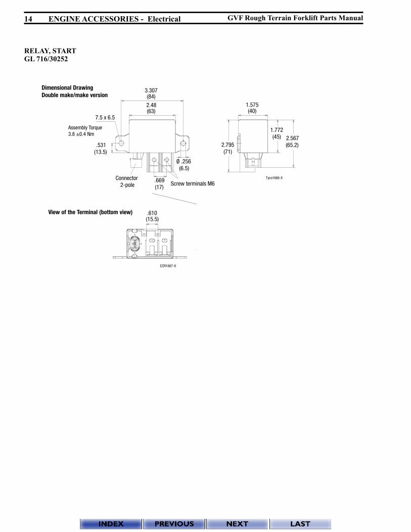
RELAY, START GL 716/30252
High Current SolutionsHigh Current Devices
High Current Relay 150
Please observe the disclaimer.
179
Catalog 1308028Revision 4-2007
Revision 03-05
Tyco1666-X
Screw terminals M6Connector
2-pole
.531
7.5 x 6.5
(13.5)
2.48(63)
3.307(84)
1.575(40)
1.772(45)
.669(17)
2.567(65.2)2.795
(71)
Ø .256(6.5)
ECR1667-6
.610(15.5)
Screw terminals M6Quick connectorssimilar to ISO 8092-1
1.575(40)
.669(17)
.669(17)
.531(13.5)
.413(10.5)
.276(7)
2.008(51)
.413(10.5)
.079(2)
.177(4.5)
2.185(55.5)
1.772(45)
2.519(64)
Tyco1452-F
.551(14)
.394(10)
2.48(63)
.610(15.5)
ECR1453-N
Dimensional DrawingDouble make/make version
Changeover Version
View of the Terminal (bottom view)
View of the Terminal (bottom view)
Connector InformationAMP Superseal 1.5. seriesCoil side- Receptacle connector 282080-1- Single wire seal 281934-2- Contact 282110-1Load side- Thimble 710026
Assembly Torque 3.8 ±0.4 Nm
ENGINE ACCESSORIES - Electrical 15GVF Rough Terrain Forklift Parts Manual
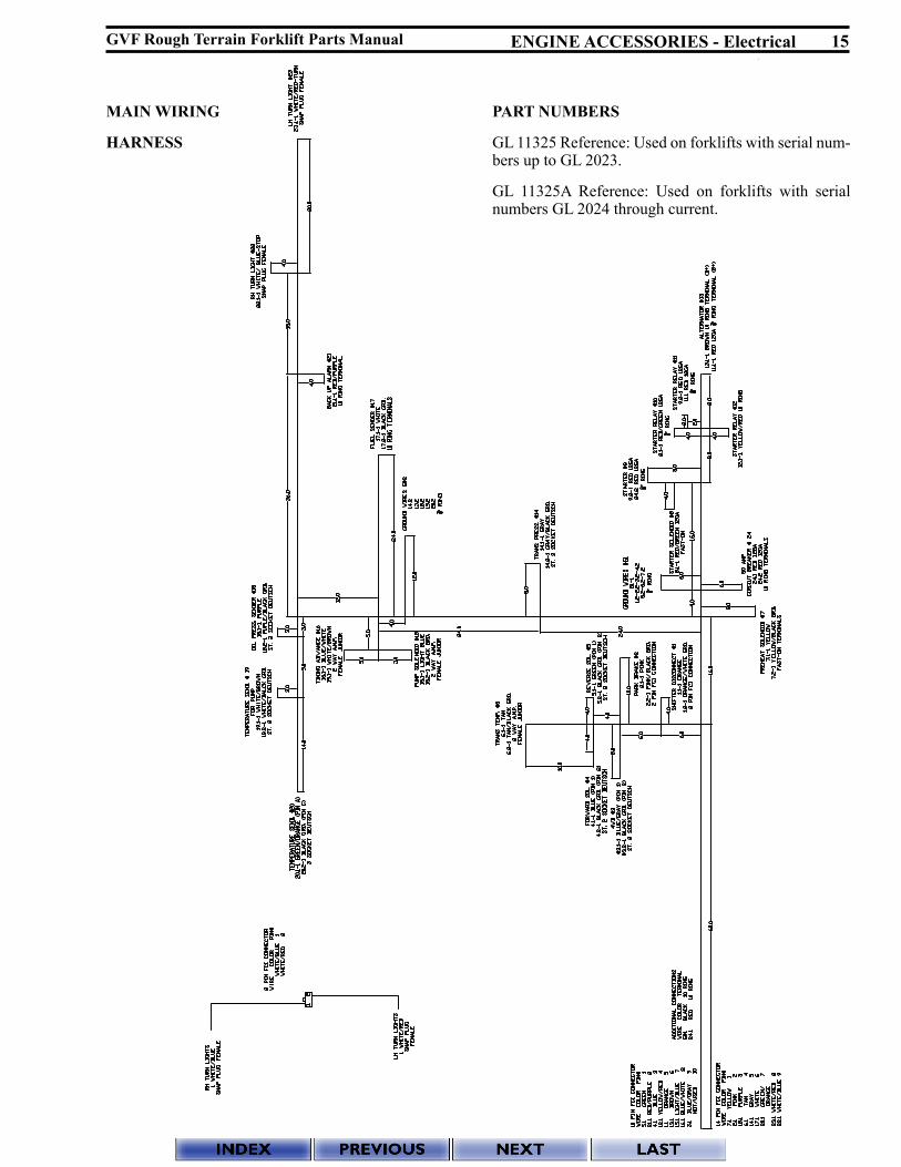
MAIN WIRING
HARNESS
PART NUMBERS
GL 11325 Reference: Used on forklifts with serial num-bers up to GL 2023.
GL 11325A Reference: Used on forklifts with serial numbers GL 2024 through current.

ENGINE ACCESSORIES - Electrical16 GVF Rough Terrain Forklift Parts Manual
FNR SWITCH WIRE HARNESS GL 11330

ENGINE ACCESSORIES - Electrical 17GVF Rough Terrain Forklift Parts Manual
WORK LIGHTS HARNESS
PART NUMBERS
GL 11340 Reference: Used on forklifts with serial num-bers up to GL 2023.
GL 11340A Reference: Used on forklifts with serial numbers GL 2024 through current.
ENGINE ACCESSORIES - Electrical18 GVF Rough Terrain Forklift Parts Manual
ADDITIONAL ELECTRICAL COMPONENTS
REFERENCE: GL 2000 - GL 2023
1. GL 11615 – Switch, Ignition – Qty = 1 2. GL 11010 – Flasher, Warning – Qty = 13. O SS581 – Solenoid – Qty = 14. GL 11605 – Relay, Bosch – Qty = 4
REFERENCE: GL 2024 - PRESENT
1. GL 11570 – Panel, Blank Control – Qty = 12. Gauges a. GL 11575 – Hourmeter – Qty = 1 b. GL 11580 – Gauge, Fuel – Qty = 1 c. GL 11585 – Voltmeter – Qty = 1 d. GL 11660 – Gauge, Water Temperature – Qty = 1 e. GL 11655 – Sender, Temperature - Qty = 13. GL 11595 – Ind. Lights, 14V Red – Qty = 54. GL 11600 – Receptacle, 12V Power – Qty = 15. GL 11620 – Switch, On/Off 4WD – Qty = 16. GL 11625 – Switch, Flasher – Qty = 17. GL 11630 – Switch, Turn Signal – Qty = 18. GL 11635 – Switch, Light – Qty = 19. GL 12000 – Connector, Electrical - Qty = 410. GL 11965 – Holder, Fuse Relay – Qty = 111. GL 11955 – Flasher, LED 4 Pin Electronic – Qty = 112. GL 11975 – Relay, Micro – Qty = 313. GO 11783 – Switch, Starter – Qty = 1 14. GL 11985 – Switch, Ignition 2 Position – Qty = 1

ENGINE ACCESSORIES - Exhaust 19GVF Rough Terrain Forklift Parts Manual
1 1
2 2
3 3
4 4
AA
BB
CC
DD
SHEE
T 1
OF
1
DR
AWN
CHEC
KED
QA
MFG
APPR
OVE
D
Mat
t9/
13/2
006
DW
G N
O
GL9
5132
TITL
E
EXH
AUST
SIZE C
SCAL
E
GIL
LISO
N'S
VAR
IETY
FAB
.
REV
1
Part
s Li
stD
ESCR
IPTI
ON
PAR
T N
UM
BER
QTY
ITEM
2 1/
2" E
XHAU
ST P
IPE
GL9
5132
11
MU
FFLE
RG
L951
331
2EX
HAU
ST M
ANIF
OLD
GL9
561
13
2 1/
2" E
XHAU
ST T
UR
NO
UT
GL9
5136
14
7/16
" CO
LD R
OU
ND
EX
HAU
ST H
ANG
ERG
L951
371
5
Part
s Li
stD
ESCR
IPTI
ON
PART
NU
MBE
RQ
TYIT
EM7/
16"
COLD
RO
UN
D
EXH
AUST
HAN
GER
GL9
5138
16
120°
90°
120°
10.7
2
8.50
7.47
4.25
9.80
CUT
TO 3
0" T
HEN
SEN
D T
O B
E BE
NT
FIRS
T BE
ND
AT
10 1
/2"
SECO
ND
AT
19"
5.00
5
2
4
1
3 90°
NO
TES:
CUT
9" L
ON
G1.
BEN
D F
IRST
AT
3 1/
2" F
ROM
1 E
ND
2. B
END
SEC
ON
D A
T 2
1/2"
FRO
M O
THER
EN
D
CUT
1 PC
AT
6" O
N 1
5°
AND
1 P
C AT
2 1
/2"
ON
15°
30°
4.25
2.50
CUT
3 1/
2" O
FF E
XHAU
ST P
IPE
3.00
90°
2.50
3.50
5.50
REV
ISIO
N H
ISTO
RY
ZON
ERE
VD
ESCR
IPTI
ON
DAT
EAP
PRO
VED
11
SHO
RTE
NED
MAN
IFO
LD3/
23/2
007
Mat
t
12
LEN
GTH
ENED
TUBE
1/2
"3/
24/2
007
Mat
t
12
5.50
PAIN
T H
IGH
TEM
P. B
LACK
46.2
9
3.00
4.00
1.50
6
EXHAUST
Reference: Used on forklifts with serial numbers up to GL 2023.
3 pc
.
G
L 121
55
M
UFF
LER
CLA
MP
2 1/
2”
WIT
H H
AN
GE
R
ENGINE ACCESSORIES - Exhaust20 GVF Rough Terrain Forklift Parts Manual
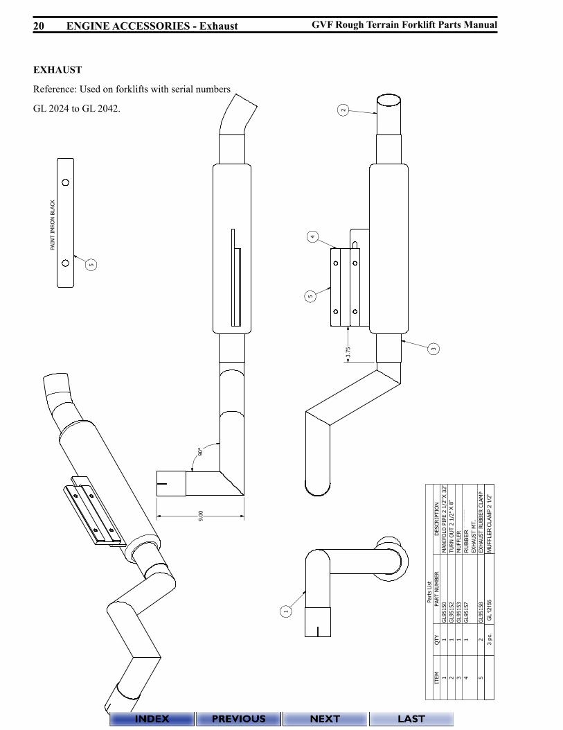
EXHAUST
Reference: Used on forklifts with serial numbers
GL 2024 to GL 2042.
1 1
2 2
3 3
4 4
AA
BB
CC
DD
SHEE
T 1
OF
1
DR
AWN
CHEC
KED
QA
MFG
APPR
OVE
D
Mat
t12
/18/
2007
DW
G N
O
GL9
5150
-1
TITL
E
EXH
AUST
GVF
500
0 20
08
SIZE C
SCAL
E
GIL
LISO
N'S
VAR
IETY
FAB
.
REV
Part
s Li
stD
ESCR
IPTI
ON
PART
NU
MBE
RQ
TYIT
EMM
ANIF
OLD
PIP
E 2
1/2"
GL9
5150
11
TURN
OU
T 2
1/2"
GL9
5152
12
MU
FFLE
RG
L951
531
31/
4" 2
PLY
RUBB
ER
EXH
AUST
MT.
GL9
5157
14
EXH
AUST
RU
BBER
CLA
MP
GL9
5158
25
9.00
90°
3.75
1
3
4
2
5
PAIN
T IM
RON
BLA
CK
5
3 pc
.
G
L 121
55
M
UFF
LER
CLA
MP
2 1/
2”X 3
2”X
8”
RU
BB
ER
ENGINE ACCESSORIES - Exhaust 21GVF Rough Terrain Forklift Parts Manual
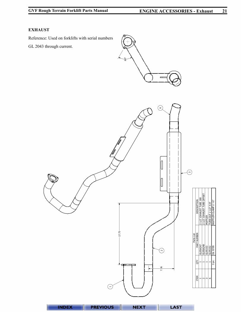
EXHAUST
Reference: Used on forklifts with serial numbers
GL 2043 through current.1 1
2 2
3 3
4 4
AA
BB
CC
DD
SHEE
T 1
OF
1
DR
AWN
CHEC
KED
QA
MFG
APPR
OVE
D
mat
t7/
14/2
008
DW
G N
O
GL9
5A24
7
TITL
E
EXH
AUST
TIE
R 3
SIZE C
SCAL
E
GIL
LISO
N'S
VAR
IETY
FAB
.
REV
Part
s Li
stD
ESCR
IPTI
ON
PAR
T N
UM
BER
QTY
ITEM
2 1/
2" E
XHAU
ST T
UBE
180
GL9
5A24
71
12
1/2"
EXH
AUST
TU
BE O
FFSE
TG
L95A
248
12
MU
FFLE
RG
L951
531
3TU
RN O
UT
2 1/
2"G
L951
521
6
7.36
17.7
5
60°
1
2
3
6
3 pc
.
G
L 121
55
MU
FFLE
R C
LAM
P 2
1/2”
X 8
”
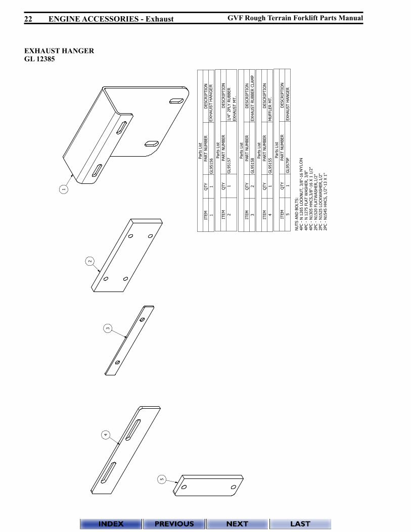
ENGINE ACCESSORIES - Exhaust22 GVF Rough Terrain Forklift Parts Manual
EXHAUST HANGERGL 12385
1 1
2 2
3 3
4 4
AA
BB
CC
DD
SHEE
T 1
OF
1
DR
AWN
CHEC
KED
QA
MFG
APPR
OVE
D
mat
t12
/22/
2008
DW
G N
O
GL1
2385
TITL
E
EXH
AUST
HAN
GER
UPD
ATE
SIZE C
SCAL
E
GIL
LISO
N'S
VAR
IETY
FAB
.
REV
Part
s Li
stD
ESCR
IPTI
ON
PART
NU
MBE
RQ
TYIT
EM3/
16"
PLAT
EG
L951
561
1
Part
s Li
stD
ESCR
IPTI
ON
PART
NU
MBE
RQ
TYIT
EM1/
4" 2
PLY
RUBB
ER
EXH
AUST
MT.
GL9
5157
12
Part
s Li
stD
ESCR
IPTI
ON
PART
NU
MBE
RQ
TYIT
EMEX
HAU
ST R
UBB
ER C
LAM
PG
L951
582
3
Part
s Li
stD
ESCR
IPTI
ON
PAR
T N
UM
BER
QTY
ITEM
MU
FFLE
R M
T.G
L951
551
4
Part
s Li
stD
ESCR
IPTI
ON
PART
NU
MBE
RQ
TYIT
EMEX
HAU
ST H
ANG
ERG
L957
9F1
5
1
2
34
5
NU
TS A
ND
BO
LTS:
4PC
- N
126
5 LO
CKN
UT,
3/8
"-16
4PC
- N
127
5 FL
AT W
ASH
ER, 3
/8"
4PC
- N
1305
HH
CS,3
/8"-
16 X
1 1
/2"
2PC
- N
1520
FLA
TWAS
HER
,1/2
"2P
C -
N15
25 L
OCK
WAS
HER
,1/2
"2P
C -
N15
45 H
HCS
, 1/2
"-13
X 1
"
EX
HA
US
T H
AN
GE
R
NY
LON
ENGINE ACCESSORIES - Filters 23GVF Rough Terrain Forklift Parts Manual
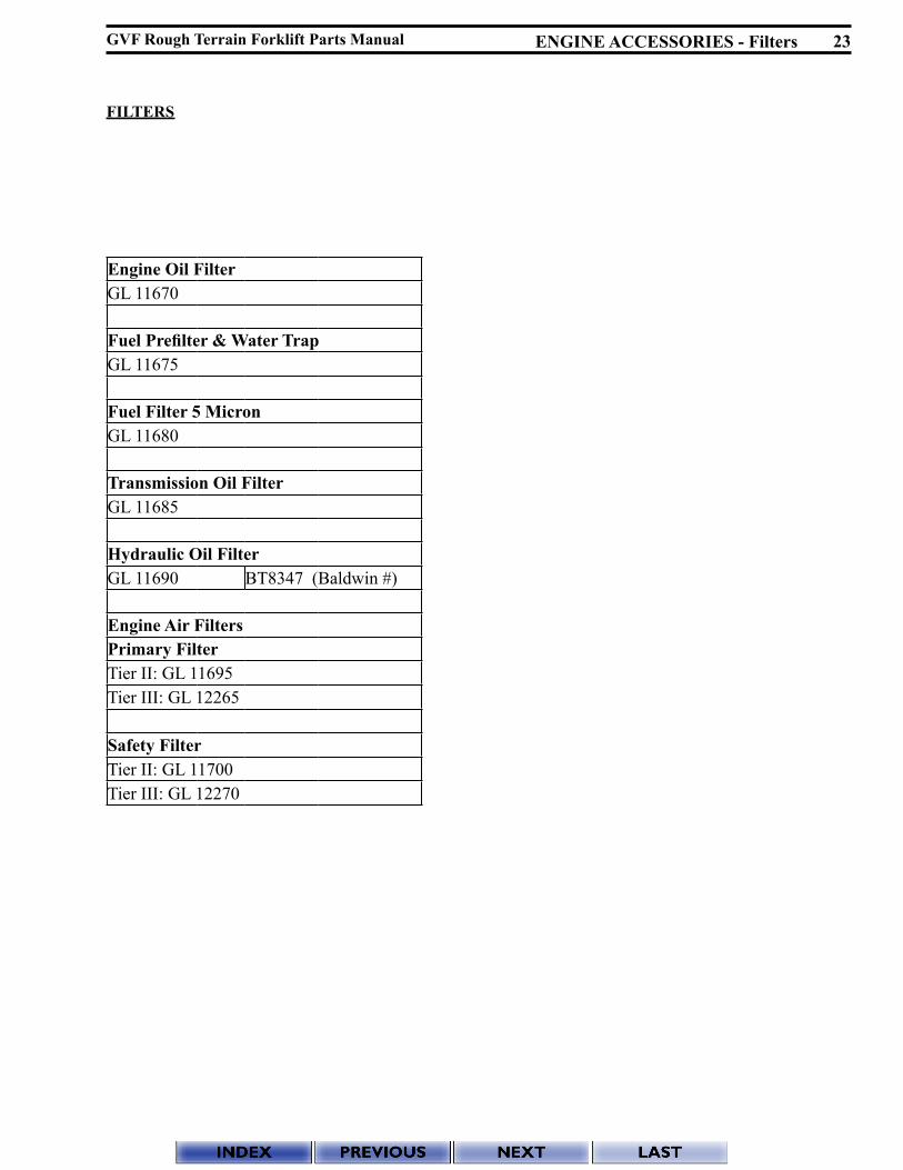
FILTERS
Engine Oil FilterGL 11670
Fuel Prefilter & Water TrapGL 11675
Fuel Filter 5 MicronGL 11680
Transmission Oil FilterGL 11685
Hydraulic Oil FilterGL 11690 BT8347 (Baldwin #)
Engine Air FiltersPrimary FilterTier II: GL 11695 Tier III: GL 12265
Safety FilterTier II: GL 11700 Tier III: GL 12270
ENGINE ACCESSORIES - Throttle24 GVF Rough Terrain Forklift Parts Manual
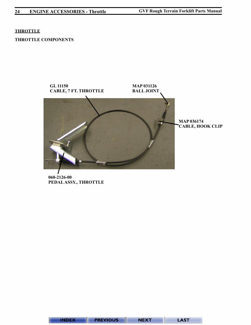
THROTTLE
THROTTLE COMPONENTS
060-2126-00PEDAL ASSY., THROTTLE
GL 11150CABLE, 7 FT. THROTTLE
MAP 031126BALL JOINT
MAP 036174CABLE, HOOK CLIP
FRAME AND SHEET METAL - Battery Box 25GVF Rough Terrain Forklift Parts Manual
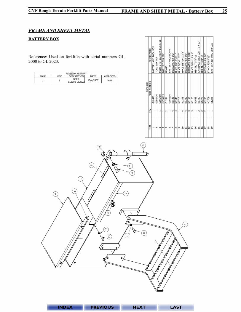
FRAME AND SHEET METAL
BATTERY BOX
1 1
2 2
3 3
4 4
AA
BB
CC
DD
SHEE
T 1
OF
1
DR
AWN
CHEC
KED
QA
MFG
APPR
OVE
D
Mat
t10
/1/2
007
DW
G N
O
GL9
5701
-1E
TITL
E
BATT
ERY
BOX
ASSE
MBL
Y
SIZE C
SCAL
E
GIL
LISO
N'S
VAR
IETY
FAB
.
REV
Part
s Li
stD
ESCR
IPTI
ON
PART
NU
MBE
RQ
TYIT
EMBA
TTER
Y AN
D T
OO
L BO
XG
L957
011
1TO
OL
BOX
TOP
GL9
5704
12
FOO
T ST
EP B
ATTE
RY B
OX
SID
EG
L957
101
3BA
TTER
Y BO
X TO
PG
L957
031
4H
ING
EO
1221
25
BATT
ERY
HO
LD D
OW
NG
L952
141
6LO
CKW
ASH
ER 1
/2"
N15
254
7H
HCS
1/2
"-13
X 1
"N
1545
48
HH
CS 5
/8"-
11 X
7"
N17
151
9H
HCS
3/8
"-16
X 3
/4"
N12
954
10LO
CKW
ASH
ER 3
/8"
N12
804
11LO
CKW
ASH
ER 5
/16"
N11
503
12H
HCS
5/1
6"-1
8 X
1"N
1170
313
HEX
NU
T 5/
8"-1
1N
1625
114
CARR
IAG
E BO
LT 3
/8"-
16 X
10"
N63
802
15H
EX N
UT
3/8"
-16
N12
702
16LO
CKW
ASH
ER 3
/8"
N12
802
17LY
NCH
PIN
5/1
6"M
2709
118
BATT
ERY
31P-
MH
D 9
50 C
CAK1
283
119
3
4
6
18
10
11
87
14
9
2
REVI
SIO
N H
ISTO
RYZO
NE
REV
DES
CRIP
TIO
ND
ATE
APPR
OVE
D
11
USE
DG
L200
0-G
L202
310
/4/2
007
Mat
t
1
5
1312
Reference: Used on forklifts with serial numbers GL 2000 to GL 2023.
1
1
2
2
3
3
4
4
A A
B B
C C
D D
SHEET 1 OF 1
DRAWN
CHECKED
QA
MFG
APPROVED
Matt 10/1/2007
DWG NO
GL95701-1E
TITLE
BATTERY BOX ASSEMBLY
SIZE
CSCALE
GILLISON'S VARIETY FAB.
REV
Parts ListDESCRIPTIONPART NUMBERQTYITEM
BATTERY AND TOOL BOXGL9570111TOOL BOX TOPGL9570412FOOT STEP BATTERY BOX SIDEGL9571013BATTERY BOX TOPGL9570314HINGEO122125BATTERY HOLD DOWNGL9521416LOCKWASHER 1/2"N152547HHCS 1/2"-13 X 1"N154548HHCS 5/8"-11 X 7"N171519HHCS 3/8"-16 X 3/4"N1295410LOCKWASHER 3/8"N1280411LOCKWASHER 5/16"N1150312HHCS 5/16"-18 X 1"N1170313HEX NUT 5/8"-11N1625114CARRIAGE BOLT 3/8"-16 X 10"N6380215HEX NUT 3/8"-16N1270216LOCKWASHER 3/8"N1280217LYNCH PIN 5/16"M2709118BATTERY 31P-MHD 950 CCAK1283119
3
4
6
18
10
11
87
14
9
2
REVISION HISTORYZONE REV DESCRIPTION DATE APPROVED
1 1 USEDGL2000-GL2023
10/4/2007 Matt
1
5
1312
FRAME AND SHEET METAL - Chassis Frame26 GVF Rough Terrain Forklift Parts Manual
1 1
2 2
3 3
4 4
AA
BB
CC
DD
SHEE
T 1
OF
1
DR
AWN
CHEC
KED
QA
MFG
APPR
OVE
D
mat
t9/
18/2
008
DW
G N
O
GVF
9500
_07P
TITL
E
SIZE C
SCAL
E
REV
67
9
10
24
4
12
11
1
21
96
8719
14
17
3
222
23
37
36
4041
43
46
28
3130
44
33
49
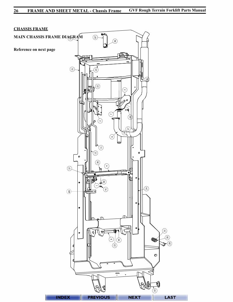
CHASSIS FRAME
MAIN CHASSIS FRAME DIAGRAM
Reference on next page
FRAME AND SHEET METAL - Chassis Frame 27GVF Rough Terrain Forklift Parts Manual
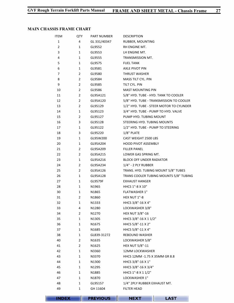
MAIN CHASSIS FRAME CHART
ITEM QTY PART NUMBER DESCRIPTION1 4 GL 331/40347 RUBBER, MOUNTING2 1 GL9552 RH ENGINE MT.3 1 GL9553 LH ENGINE MT.4 1 GL9555 TRANSMISSION MT.5 1 GL9575 FUEL TANK6 1 GL9581 AXLE PIVOT PIN7 2 GL9580 THRUST WASHER8 2 GL9584 MASS TILT CYL. PIN 9 2 GL9585 TILT CYL. PIN 10 2 GL9586 MAST MOUNTING PIN11 2 GL95A121 5/8" HYD. TUBE ‐ HYD. TANK TO COOLER12 2 GL95A120 5/8" HYD. TUBE ‐ TRANSMISSION TO COOLER13 2 GL95129 1/2" HYD. TUBE ‐ STEER MOTOR TO CYLINDER14 1 GL95123 3/4" HYD. TUBE ‐ PUMP TO HYD. VALVE15 2 GL95127 PUMP HYD. TUBING MOUNT16 3 GL95128 STEERING HYD. TUBING MOUNTS17 1 GL95122 1/2" HYD. TUBE ‐ PUMP TO STEERING18 3 GL95220 1/8" PLATE19 1 GL95W200 CAST WEIGHT 2500 LBS20 1 GL95A204 HOOD PIVOT ASSEMBLY21 2 GL95A209 FILLER PANEL22 2 GL95A215 LOWER GAS SPRING MT.23 1 GL95A216 BLOCK OFF UNDER RADIATOR24 2 GL95A234 1/4" ‐ 2 PLY RUBBER25 2 GL95A126 TRANS. HYD. TUBING MOUNT 5/8" TUBES26 1 GL95A128 TRANS COOLER TUBING MOUNTS 5/8" TUBING27 1 GL9579F EXHAUST HANGER28 1 N1965 HHCS 1"‐8 X 10" 30 1 N1865 FLATWASHER 1"31 2 N1860 HEX NUT 1"‐832 1 N1333 HHCS 3/8"‐16 X 4"33 4 N1280 LOCKWASHER 3/8"34 2 N1270 HEX NUT 3/8"‐1635 1 N1305 HHCS 3/8"‐16 X 1 1/2"36 1 N1675 HHCS 5/8"‐11 X 2"37 1 N1685 HHCS 5/8"‐11 X 4"38 1 GL839‐31272 REBOUND WASHER40 2 N1635 LOCKWASHER 5/8"41 2 N1625 HEX NUT 5/8"‐1142 1 N3360 12MM LOCKWASHER43 1 N3370 HHCS 12MM ‐1.75 X 35MM GR 8.844 1 N1300 HHCS 3/8"‐16 X 1"45 1 N1295 HHCS 3/8"‐16 X 3/4"46 1 N1885 HHCS 1"‐8 X 1 1/2"47 1 N1870 LOCKWASHER 1"48 1 GL95157 1/4" 2PLY RUBBER EXHAUST MT.49 1 GH 11604 FILTER HEAD
FRAME AND SHEET METAL - Decals28 GVF Rough Terrain Forklift Parts Manual
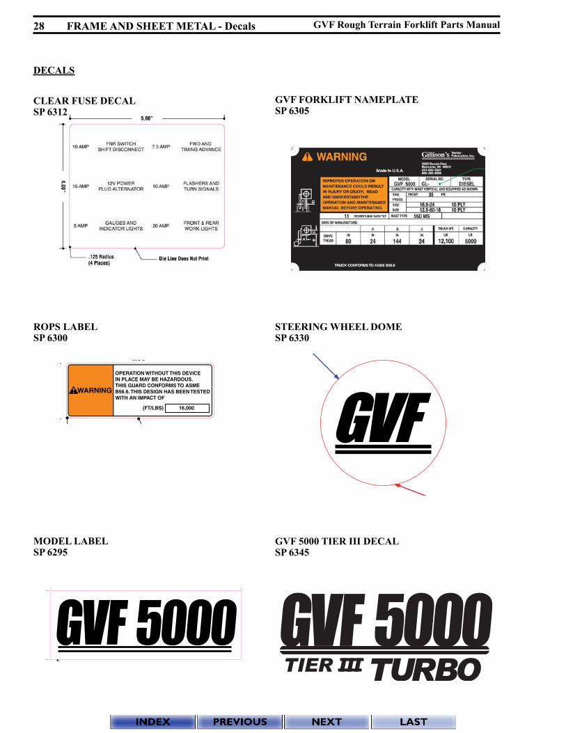
DECALS
CLEAR FUSE DECALSP 6312
GVF FORKLIFT NAMEPLATESP 6305
MODEL LABELSP 6295
ROPS LABELSP 6300
GVF
COLOR(S) SHOWN REPRESENT COLOR LAYOUT ONLY AND ARE NOT A TRUE COLOR MATCH.
Please look over carefully and verify that this proof meets your requirements.It is the responsibility of the customer to notify us of any changes.
Thank You for your order!
06.27.2007
GVF Dome 1 color
172286
Doug Kuehn
APPROVED Proceed with production
APPROVED w/ REVISIONSRevise, proceed with production
REJECTED Revise and re-proof
THE CUSTOMER IS RESPONSIBLE TO VERIFY & APPROVE GRAPHICS/DIMENSIONS WHEN
APPROVING PROOF:
Graphics/Dimensions approved by:
Date:
If proof is not approved within 30 days, we will invoice you for the
artwork only, less film cost.
1st PROOFGillison’s Variety Fabrication, Inc
Ø 1.875"
Die Line Does Not Print
PROOF Gillison’s Variety Fabrication, Inc. P/N: GVF Dome 1 Color MACAI12 RLP 06.27.2007 SIZE: 1.875 Diameter
.004 Hard White Vinyl w/ 2 mils of #14 Adh. w/ 25# Quilon C2S Tissue Lamination w/Doming1 - BLACK DIE LINE does not print
STEERING WHEEL DOMESP 6330
GVF 5000 TIER III DECALSP 6345

FRAME AND SHEET METAL - Decals 29GVF Rough Terrain Forklift Parts Manual
FORKLIFT DECAL SET26 TOTALSP 6280
FRAME AND SHEET METAL - Firewall30 GVF Rough Terrain Forklift Parts Manual
1 1
2 2
3 3
4 4
AA
BB
CC
DD
SHEE
T 1
OF
1
DR
AWN
CHEC
KED
QA
MFG
APPR
OVE
D
mat
t7/
23/2
009
DW
G N
O
GL9
5A20
3AP
TITL
E
FIR
E W
ALL
SIZE C
SCAL
E
GIL
LISO
N'S
VAR
IETY
FAB
.
REV
Part
s Li
stD
ESCR
IPTI
ON
PAR
T N
UM
BER
QTY
ITEM
FIRE
WAL
L TI
ER 3
GL9
5A20
31
1H
OO
D G
UID
EG
L95A
213
22
OVE
RFLO
W T
ANK
MO
UN
TIN
G T
UBE
S TI
ER3
3/8"
I.D
. X 3
/4"
O.D
. DO
MG
L95A
217A
23
FILT
ER A
SSY,
FU
ELG
L320
-071
401
4TA
NK
EXPA
NSI
ON
GL1
28-1
5313
15
BATT
ERY
LUG
, REM
OTE
GL1
1980
16
FLAT
WAS
HER
3/8
"N
1275
37
LOCK
WAS
HER
3/8
"N
1280
28
HH
CS 3
/8"-
16 X
3/4
"N
1295
19
HH
CS 3
/8"-
16 X
1"
N13
001
10H
EX N
UT
3/8"
-16
N12
701
11CA
RRIA
GE
BOLT
, 3/8
-16
X 6
N63
501
12CA
P, E
NPA
NSI
ON
TAN
KG
L477
-002
231
13H
EX N
UT
1/4"
-20
N10
102
14FL
ATW
ASH
ER 1
/4"
N10
151
15LO
CKW
ASH
ER 1
/4"
N10
202
16CA
RRIA
GE
BOLT
, 3/8
-16
X 6
N60
351
17M
OD
ULE
, PO
WER
REL
AYG
L119
601
18FU
SE,2
0 AM
P SL
OW
BLO
WG
L122
051
18A
FUSE
,50
AMP
SLO
W B
LOW
GL1
2210
118
BH
HCS
1/4
"-20
X 2
"N
1050
119
19
16
146
18
4
7
8
10
7
89
117
5
12
13
1416
1517
2
3
1
REVI
SIO
N H
ISTO
RY
REV
DES
CRIP
TIO
ND
ATE
1U
SED
G
L202
4-CU
RREN
T7/
23/2
009
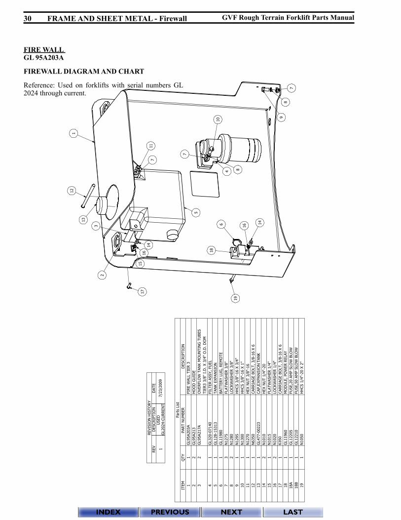
FIRE WALL GL 95A203A
FIREWALL DIAGRAM AND CHART
Reference: Used on forklifts with serial numbers GL 2024 through current.
A
EX
PAN
SIO
N
6350
FRAME AND SHEET METAL - FOPS 31GVF Rough Terrain Forklift Parts Manual
1 1
2 2
3 3
4 4
AA
BB
CC
DD
SHEE
T 1
OF
1
DR
AWN
CHEC
KED
QA
MFG
APPR
OVE
D
mat
t2/
27/2
008
DW
G N
O
GL9
5775
-1
TITL
E
FOPS
PAR
TS B
REAK
DO
WN
GVF
500
0
SIZE C
SCAL
E
GIL
LISO
N'S
VAR
IETY
FAB
.
REV
Part
s Li
stD
ESCR
IPTI
ON
PAR
T N
UM
BER
QTY
ITEM
FOPS
FR
AME
WO
RK 4
4"
CLEA
RAN
CE B
ETW
EEN
SEA
T BO
TTO
M O
F FR
AMEW
ORK
GL9
5775
11
WAR
NIN
G B
EACO
NG
VF10
101
2
MIR
ROR
5"
GL1
1385
13
LAM
P CO
MPO
SITE
WO
RK 1
2VG
L119
154
4BU
LB R
EPLA
CEM
ENT
GL1
1916
45
HH
CS 1
/2"-
13 X
2"
N15
552
6LO
CKW
ASH
ER 1
/2"
N15
252
7H
EX N
UT
1/2"
13N
1515
28
HEX
NU
T 5/
8"-1
1N
1625
29
LOCK
WAS
HER
5/8
"N
1635
210
HH
CS 5
/8"-
11 X
1 1
/2"
N16
602
11FH
CS 1
0-32
X 3
/4"
N40
203
12N
UT
10-3
2N
9420
313
HAR
NES
S W
ORK
LIG
HT
(NO
T IL
LIST
RATE
D)
GL1
1340
A2
14
4
5
2
12
11
10
9
8
7
6
3
1
REVI
SIO
N H
ISTO
RYZO
NE
REV
DES
CRIP
TIO
ND
ATE
APPR
OVE
D
11
USE
D
GL2
000-
CURR
ENT
9/10
/200
8m
att
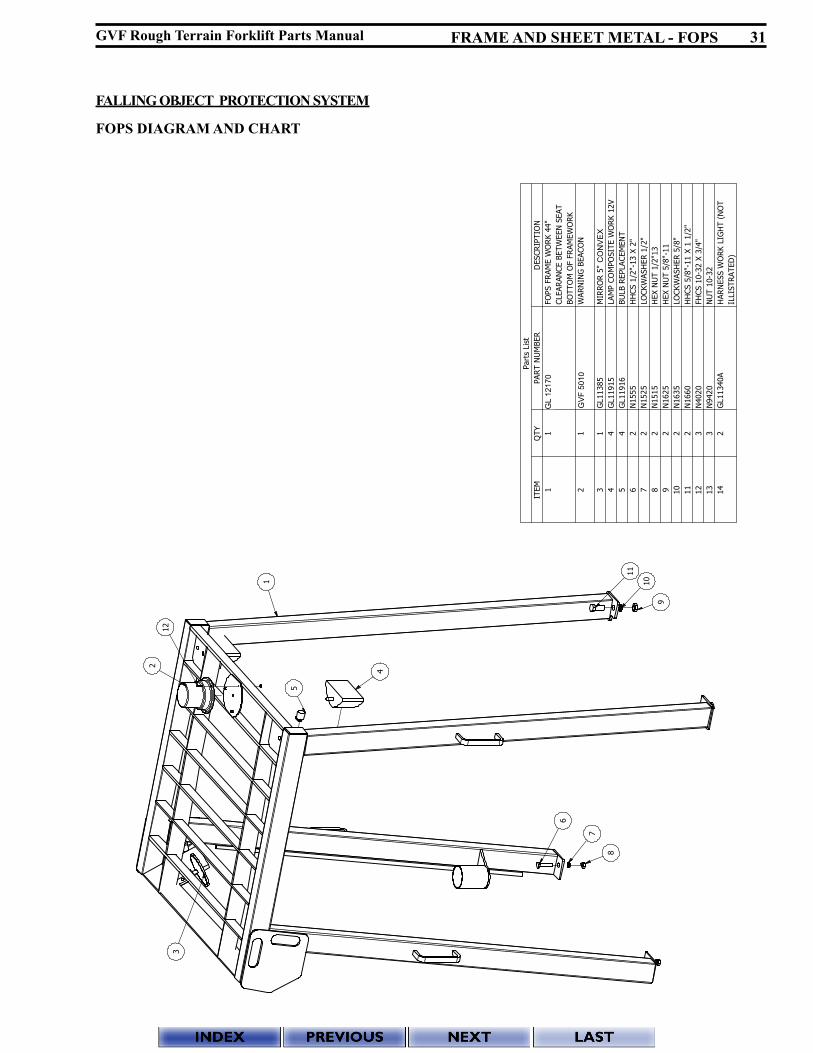
FALLING OBJECT PROTECTION SYSTEM
FOPS DIAGRAM AND CHART
GL
1217
0
GV
F 50
10
CO
NV
EX

FRAME AND SHEET METAL - Fuel Tank32 GVF Rough Terrain Forklift Parts Manual1 1
2 2
3 3
4 4
AA
BB
CC
DD
SHEE
T 1
OF
1
DR
AWN
CHEC
KED
QA
MFG
APPR
OVE
D
Mat
t10
/1/2
007
DW
G N
O
GL9
575E
TITL
E
FUEL
TAN
K PA
RTS
BR
EAKD
OW
N
SIZE C
SCAL
E
GIL
LISO
N'S
VAR
IETY
FAB
.
REV
Part
s Li
stD
ESCR
IPTI
ON
PART
NU
MBE
RQ
TYIT
EMFU
EL T
ANK
GL9
576
11
HH
CS 1
/2"-
13 X
1"
N15
454
2LO
CKW
ASH
ER 1
/2"
N15
254
3H
HCS
3/8
"-16
X 3
/4"
N12
954
4LO
CKW
ASH
ER 3
/8"
N12
804
5FI
LLER
CAP
ASS
EMBL
YG
1066
16
FUEL
SEN
DER
GAS
KET
9606
419
17
FUEL
LEV
EL S
END
ING
UN
ITG
L113
501
8N
UT
AND
BO
LT P
ACK
FUEL
SEN
DER
9602
097-
71
9H
OSE
BARB
5/1
6" -
3/8
"NPT
90
H42
90-5
-62
101/
2" N
PT P
LUG
H10
551
11AN
TI S
LIP
TREA
D S
OLD
PER
-FT
O11
851
12TA
NK
REIN
FORC
EMEN
TG
L957
9D2
131/
2" P
LATE
GL9
5713
214
STEP
ASS
EMBL
Y FU
EL T
ANK
SID
EG
L957
501
15
45
23
67
8
1
NO
TE:
ITEM
8 I
NCL
UD
ESIT
EMS
7 AN
D 9
REV
ISIO
N H
ISTO
RYZO
NE
REV
DES
CRIP
TIO
ND
ATE
APPR
OVE
D
11
USE
DG
L200
0-CU
RRE
NT
10/3
/200
7M
att
10
15
11
FUEL TANK
FUEL TANK DIAGRAM AND CHART
Reference: Used on forklifts with serial numbers GL 2000 through current.
1 1
2 2
3 3
4 4
AA
BB
CC
DD
SHEE
T 1
OF
1
DR
AWN
CHEC
KED
QA
MFG
APPR
OVE
D
Mat
t10
/1/2
007
DW
G N
O
GL9
575E
TITL
E
FUEL
TAN
K PA
RTS
BR
EAKD
OW
N
SIZE C
SCAL
E
GIL
LISO
N'S
VAR
IETY
FAB
.
REV
Part
s Li
stD
ESCR
IPTI
ON
PART
NU
MBE
RQ
TYIT
EMFU
EL T
ANK
GL9
576
11
HH
CS 1
/2"-
13 X
1"
N15
454
2LO
CKW
ASH
ER 1
/2"
N15
254
3H
HCS
3/8
"-16
X 3
/4"
N12
954
4LO
CKW
ASH
ER 3
/8"
N12
804
5FI
LLER
CAP
ASS
EMBL
YG
1066
16
FUEL
SEN
DER
GAS
KET
9606
419
17
FUEL
LEV
EL S
END
ING
UN
ITG
L113
501
8N
UT
AND
BO
LT P
ACK
FUEL
SEN
DER
9602
097-
71
9H
OSE
BARB
5/1
6" -
3/8
"NPT
90
H42
90-5
-62
101/
2" N
PT P
LUG
H10
551
11AN
TI S
LIP
TREA
D S
OLD
PER
-FT
O11
851
12TA
NK
REIN
FORC
EMEN
TG
L957
9D2
131/
2" P
LATE
GL9
5713
214
STEP
ASS
EMBL
Y FU
EL T
ANK
SID
EG
L957
501
15
45
23
67
8
1
NO
TE:
ITEM
8 I
NCL
UD
ESIT
EMS
7 AN
D 9
REV
ISIO
N H
ISTO
RYZO
NE
REV
DES
CRIP
TIO
ND
ATE
APPR
OVE
D
11
USE
DG
L200
0-CU
RRE
NT
10/3
/200
7M
att
10
15
11
G 1
065
1 1/
4 TA
NK
FIT
TIN
G
GL
1251
5FU
EL
TAN
K A
SS
EM
BLY
FRAME AND SHEET METAL - Hood 33GVF Rough Terrain Forklift Parts Manual
1 1
2 2
3 3
4 4
AA
BB
CC
DD
SHEE
T 1
OF
1
DR
AWN
CHEC
KED
QA
MFG
APPR
OVE
D
mat
t9/
11/2
008
DW
G N
O
GL9
5A20
0P
TITL
E
FLIP
UP
HO
OD
SIZE C
SCAL
E
GIL
LISO
N'S
VAR
IETY
FAB
.
REV
Part
s Li
stD
ESCR
IPTI
ON
PART
NU
MBE
RQ
TYIT
EMH
OO
D F
ORM
ED T
IER
11
ENG
INE
GL9
5A20
01
1H
OO
D F
ORM
ED T
IER
111
EN
GIN
EG
L95A
200A
11A
2" U
HM
W H
OO
D G
UID
EG
L95A
211
22
GR
OM
MET
RU
BBER
GL1
1990
23
LAM
P, L
ED A
MBE
RG
L110
952
4H
HCS
1/4
"-20
X 3
1/2
"N
1065
25
FLAT
WAS
HER
1/4
"N
1015
26
LOCK
NU
T 1/
4"-2
0 N
YLO
N I
NSE
RT
N10
052
7LA
TCH
GL1
1860
28
SPRI
NG
, 90
LB
GL1
1950
29
HH
CS 5
/16"
-18
X 1"
N11
702
10H
EX N
UT
5/16
"-18
N11
402
1143
2 75
6
REV
ISIO
N H
ISTO
RYRE
VS/
ND
ATE
1U
SED
G
L202
4-CU
RRE
NT
9/11
/200
8
9
1110
1
8
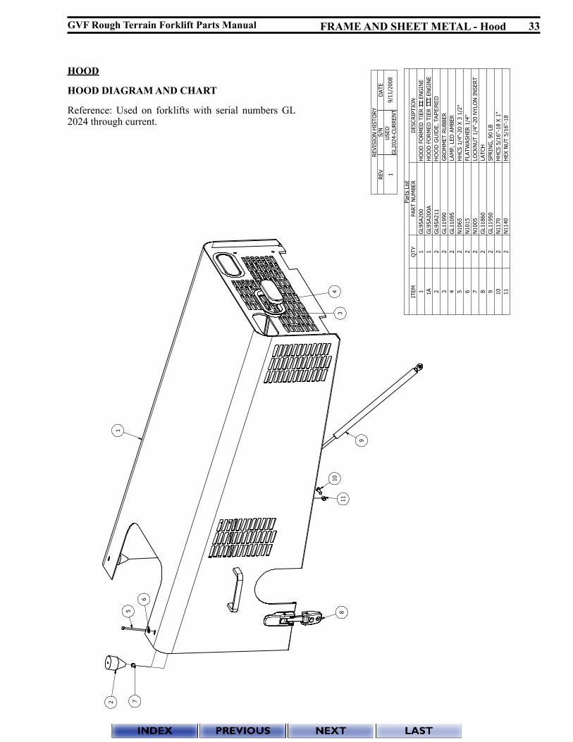
HOOD
HOOD DIAGRAM AND CHART
Reference: Used on forklifts with serial numbers GL 2024 through current.
HO
OD
GU
IDE
, TA
PE
RE
D
FRAME AND SHEET METAL - Hood34 GVF Rough Terrain Forklift Parts Manual
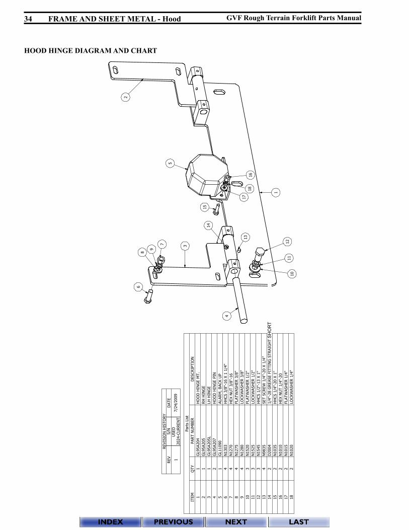
HOOD HINGE DIAGRAM AND CHART1 1
2 2
3 3
4 4
AA
BB
CC
DD
SHEE
T 1
OF
1
DR
AWN
CHEC
KED
QA
MFG
APPR
OVE
D
mat
t7/
24/2
009
DW
G N
O
GL9
5A20
4P
TITL
E
HO
OD
HIN
GE
SIZE C
SCAL
E
GIL
LISO
N'S
VAR
IETY
FAB
.
REV
Part
s Li
stD
ESCR
IPTI
ON
PAR
T N
UM
BER
QTY
ITEM
HO
OD
HIN
GE
MT.
GL9
5A20
41
1RH
HIN
GE
GL9
5A20
51
2LH
HIN
GE
GL9
5A20
5L1
3H
OO
D H
ING
E PI
NG
L95A
207
24
ALAR
M, B
ACK
UP
GL1
1090
15
HH
CS 3
/8"-
16 X
1 1
/4"
N13
034
6H
EX N
UT
3/8"
-16
N12
704
7FL
ATW
ASH
ER 3
/8"
N12
754
8LO
CKW
ASH
ER 3
/8"
N12
804
9FL
ATW
ASH
ER 1
/2"
N15
203
10LO
CKW
ASH
ER 1
/2"
N15
253
11H
HCS
1/2
"-13
X 1
"N
1545
312
SET
SCR
EW 1
/4"-
20 X
1/4
"N
9835
413
1/4"
-28
GRE
ASE
FITT
ING
STR
AIG
HT
D20
042
14H
HCS
1/4
"-20
X 1
"N
1035
215
HEX
NU
T 1/
4"-2
0N
1010
216
FLAT
WAS
HER
1/4
"N
1015
217
LOCK
WAS
HER
1/4
"N
1020
218
68
9
7
14
1011
12
15
1718
16
5
2
3
1
13
4
REVI
SIO
N H
ISTO
RYR
EVS/
ND
ATE
1U
SED
2024
-CU
RRE
NT
7/24
/200
9
SH
OR
T
FRAME & SHEET METAL - Operator’s Platform 35GVF Rough Terrain Forklift Parts Manual
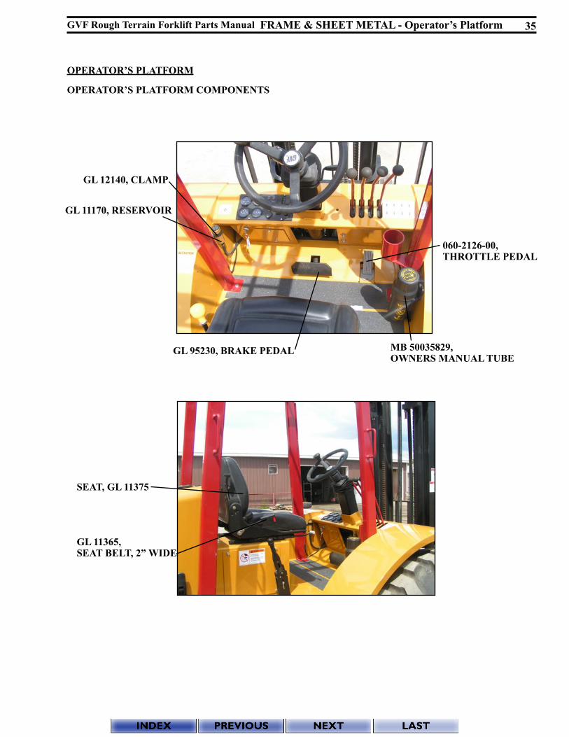
OPERATOR’S PLATFORM
OPERATOR’S PLATFORM COMPONENTS
GL 12140, CLAMP
GL 11170, RESERVOIR
GL 95230, BRAKE PEDAL
060-2126-00, THROTTLE PEDAL
MB 50035829, OWNERS MANUAL TUBE
GL 11365, SEAT BELT, 2” WIDE
SEAT, GL 11375
FRAME & SHEET METAL - Operator’s Platform36 GVF Rough Terrain Forklift Parts Manual
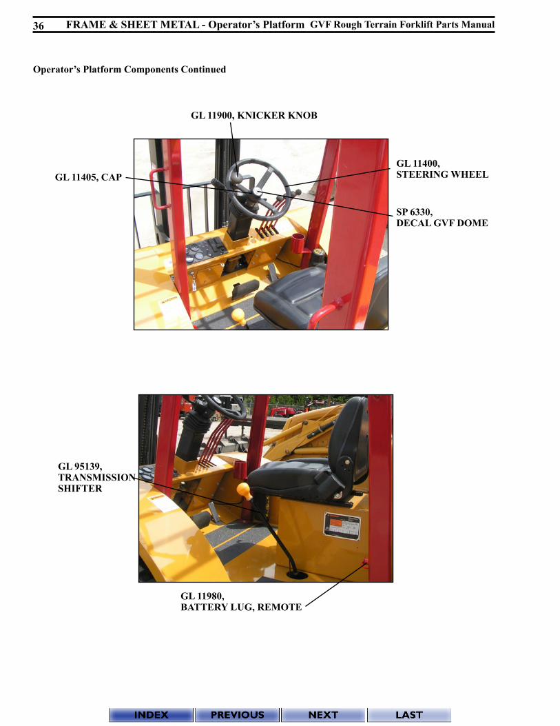
GL 11405, CAPGL 11400, STEERING WHEEL
SP 6330, DECAL GVF DOME
GL 95139, TRANSMISSION SHIFTER
GL 11980, BATTERY LUG, REMOTE
GL 11900, KNICKER KNOB
Operator’s Platform Components Continued
FRAME AND SHEET METAL - Paint 37GVF Rough Terrain Forklift Parts Manual
PAINT
YELLOW SP 3164 (GAL)
RED SP 3165 (GAL)
BLACK SP 3166 (GAL)
SPRAY CANS:
G 2020 GVF RED AEROSOL
G 2015 GVF YELLOW AEROSOL
FRAME AND SHEET METAL - Weight Box38 GVF Rough Terrain Forklift Parts Manual1 1
2 2
3 3
4 4
AA
BB
CC
DD
SHEE
T 1
OF
1
DR
AWN
CHEC
KED
QA
MFG
APPR
OVE
D
mat
t9/
11/2
008
DW
G N
O
GL9
533P
TITL
E
WEI
GH
T BO
X
SIZE C
SCAL
E
GIL
LISO
N'S
VAR
IETY
FAB
.
REV
Part
s Li
stD
ESCR
IPTI
ON
PART
NU
MBE
RQ
TYIT
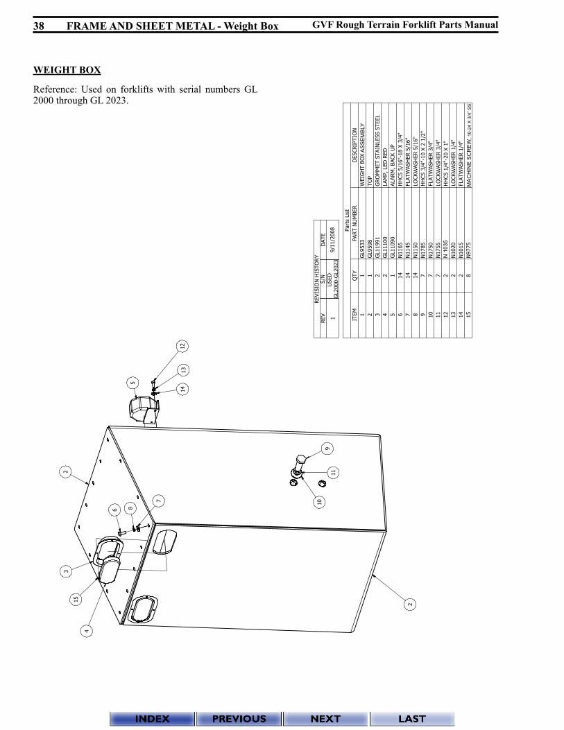
EMW
EIG
HT
BOX
GL9
533
11
TOP
GL9
598
12
GRO
MM
ET S
TAIN
LESS
STE
ELG
L119
912
3LA
MP,
LED
RED
GL1
1100
24
ALAR
M, B
ACK
UP
GL1
1090
15
HH
CS 5
/16"
-18
X 3/
4"N
1165
146
FLAT
WAS
HER
5/1
6"N
1145
147
LOCK
WAS
HER
5/1
6"N
1150
148
HH
CS 3
/4"-
10 X
2 1
/2"
N17
857
9FL
ATW
ASH
ER 3
/4"
N17
507
10LO
CKW
ASH
ER 3
/4"
N17
557
11H
HCS
1/4
"-20
X 1
"N
1030
212
LOCK
WAS
HER
1/4
"N
1020
213
FLAT
WAS
HER
1/4
"N
1015
214
FHCS
10-
24 X
3/4
" SS
N97
758
15
5
1413
12
10
119
4
15
3
6 8
7
2
2
REVI
SIO
N H
ISTO
RY
REV
S/N
DAT
E
1U
SED
G
L200
0-G
L202
39/
11/2
008
WEIGHT BOX
Reference: Used on forklifts with serial numbers GL 2000 through GL 2023.
AS
SE
MB
LY
N 1
035
MA
CH
INE
SC
RE
W, 1
0-24
X 3
/4” S
S
HYDRAULIC SYSTEM - Control Valve 39GVF Rough Terrain Forklift Parts Manual
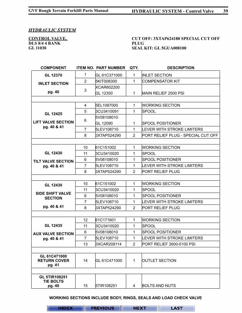
COMPONENT ITEM NO. PART NUMBER QTY. DESCRIPTION
GL 12370
INLET SECTION
pg. 40
1 GL 61C371000 1 INLET SECTION2 5KIT008300 1 COMPENSATOR KIT
3XCAR602200GL 12350 1 MAIN RELIEF 2500 PSI
GL 12425
LIFT VALVE SECTION pg. 40 & 41
4 5EL1087000 1 WORKING SECTION5 3CU3410091 1 SPOOL
65V08108010GL 12090 1 SPOOL POSITIONER
7 5LEV108710 1 LEVER WITH STROKE LIMITERS8 3XTAP524290 2 PORT RELIEF PLUG - SPECIAL CUT OFF
GL 12430
TILT VALVE SECTION pg. 40 & 41
10 61C151002 1 WORKING SECTION11 3CU3410020 1 SPOOL6 5V08108010 1 SPOOL POSITIONER7 5LEV108710 1 LEVER WITH STROKE LIMITERS8 3XTAP524290 2 PORT RELIEF PLUG
GL 12430
SIDE SHIFT VALVE SECTION
pg. 40 & 41
10 61C151002 1 WORKING SECTION11 3CU3410020 1 SPOOL6 5V08108010 1 SPOOL POSITIONER7 5LEV108710 1 LEVER WITH STROKE LIMITERS8 3XTAP524290 2 PORT RELIEF PLUG
GL 12435
AUX VALVE SECTION pg. 40 & 41
12 61C171601 1 WORKING SECTION11 3CU3410020 1 SPOOL6 5V08108010 1 SPOOL POSITIONER7 5LEV108710 1 LEVER WITH STROKE LIMITERS
13 3XCAR208114 2 PORT RELIEF 2600-5100 PSI
GL 61C471000RETURN COVER
pg. 4114 GL 61C471000 1 OUTLET SECTION
GL 5TIR108251TIE BOLTS
pg. 40 15 5TIR108251 4 BOLTS AND NUTS
WORKING SECTIONS INCLUDE BODY, RINGS, SEALS AND LOAD CHECK VALVE
HYDRAULIC SYSTEM
CONTROL VALVE, DLS 8/4 4 BANKGL 11030
CUT OFF: 3XTAP624180 SPECIAL CUT OFF PLUGSEAL KIT: GL 5GUA008100
HYDRAULIC SYSTEM - Control Valve40 GVF Rough Terrain Forklift Parts Manual
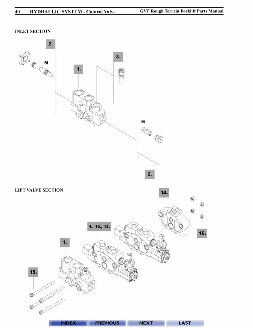
INLET SECTION
LIFT VALVE SECTION
HYDRAULIC SYSTEM - Control Valve 41GVF Rough Terrain Forklift Parts Manual
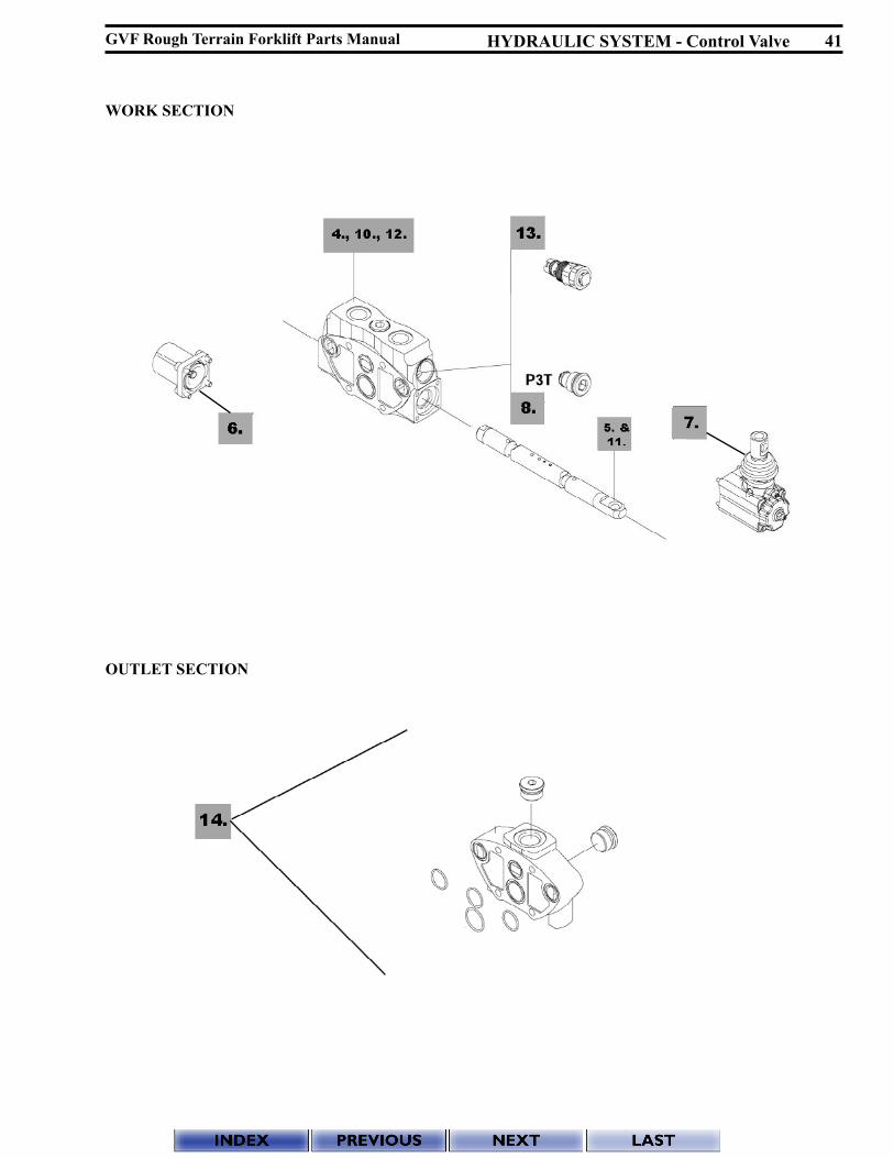
OUTLET SECTION
WORK SECTION
GVF Forklift Parts ManualHYDRAULIC SYSTEM - Valve Pivot Assembly42
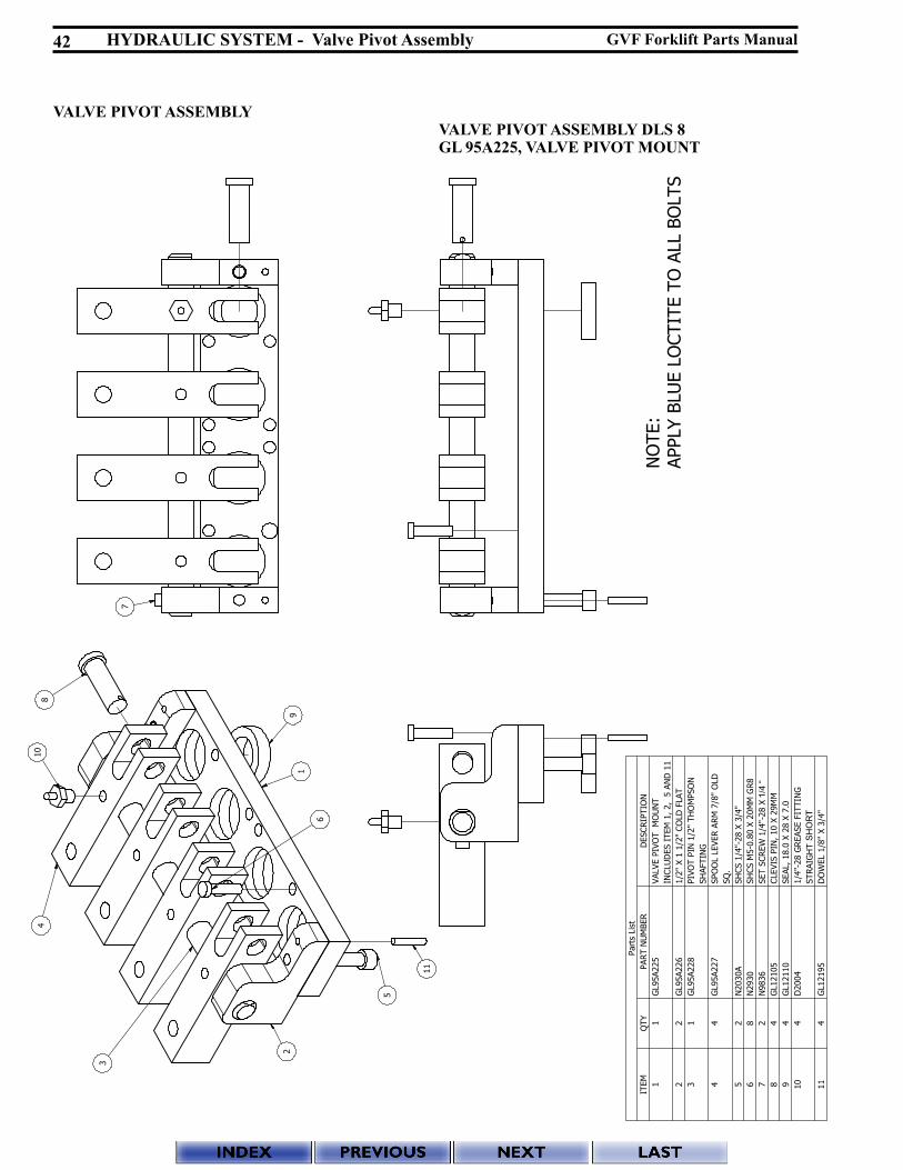
VALVE PIVOT ASSEMBLY
1 1
2 2
3 3
4 4
AA
BB
CC
DD
SHEE
T 1
OF
1
DR
AWN
CHEC
KED
QA
MFG
APPR
OVE
D
mat
t3/
12/2
008
DW
G N
O
GL9
5A22
5P
TITL
E
VALV
E PI
VOT
ASSE
MBL
Y D
LS 8
SIZE C
SCAL
E
GIL
LISO
N'S
VAR
IETY
FAB
.
REV
Part
s Li
stD
ESCR
IPTI
ON
PART
NU
MBE
RQ
TYIT
EMVA
LVE
PIVO
T M
OU
NT
INCL
UD
ES I
TEM
1, 2
, 5
AND
11
GL9
5A22
51
1
1/2"
X 1
1/2
" CO
LD F
LAT
GL9
5A22
62
2PI
VOT
PIN
1/2
" TH
OM
PSO
N
SHAF
TIN
GG
L95A
228
13
SPO
OL
LEVE
R A
RM 7
/8"
OLD
SQ
.G
L95A
227
44
SHCS
1/4
"-28
X 3
/4"
N20
30A
25
SHCS
M5-
0.80
X 2
0MM
GR8
N29
308
6SE
T SC
REW
1/4
"-28
X 3
/4"
N98
362
7CL
EVIS
PIN
, 10
X 29
MM
GL1
2105
48
SEAL
, 18.
0 X
28 X
7.0
GL1
2110
49
1/4"
-28
GR
EASE
FIT
TIN
G
STRA
IGH
TD
2004
410
DO
WEL
1/8
" X
3/4"
GL1
2195
411
108
4
19
5
6
3
7
NO
TE:
APPL
Y BL
UE
LOCT
ITE
TO A
LL B
OLT
S
11
2
1/4
“
SH
OR
T
VALVE PIVOT ASSEMBLY DLS 8GL 95A225, VALVE PIVOT MOUNT
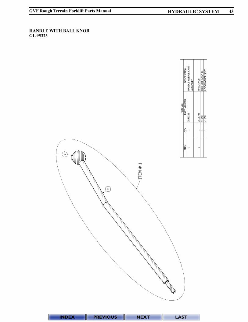
HYDRAULIC SYSTEM 43GVF Rough Terrain Forklift Parts Manual1 1
2 2
3 3
4 4
AA
BB
CC
DD
SHEE
T 1
OF
1
DR
AWN
CHEC
KED
QA
MFG
APPR
OVE
D
Mat
t10
/1/2
007
DW
G N
O
GL9
5323
TITL
E
HAN
DLE
W/B
ALL
KNO
B
SIZE C
SCAL
E
GIL
LISO
N'S
VAR
IETY
FAB
.
REV
Part
s Li
stD
ESCR
IPTI
ON
PART
NU
MBE
RQ
TYIT
EMH
AND
LE W
/BAL
L KN
OB
ASSE
MBL
YG
L953
231
1
HAN
DLE
BAR
EG
L951
391
2BA
LL K
NO
BG
L117
451
3H
EX N
UT
5/16
"-18
N11
401
4LO
CKW
ASH
ER 5
/16"
N11
501
5H
HCS
10-
1.5
X 20
MM
N33
191
6
3
2
ITEM
# 1
HANDLE WITH BALL KNOBGL 95323
HYDRAULIC SYSTEM - Cylinders44 GVF Rough Terrain Forklift Parts Manual
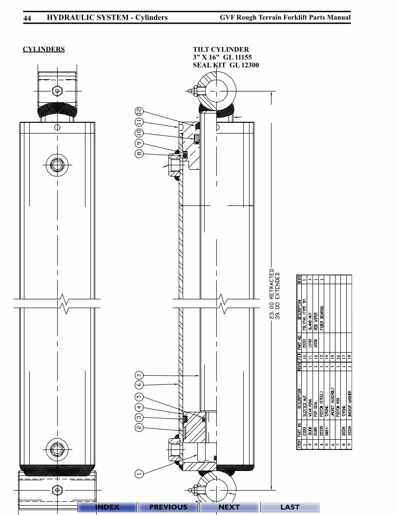
TILT CYLINDER 3” X 16” GL 11155 SEAL KIT GL 12300
CYLINDERS
45HYDRAULIC SYSTEM - CylindersGVF Rough Terrain Forklift Parts Manual
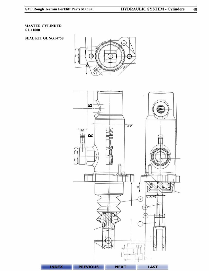
MASTER CYLINDERGL 11800
SEAL KIT GL SG14758
HYDRAULIC SYSTEM - Cylinders46 GVF Rough Terrain Forklift Parts Manual
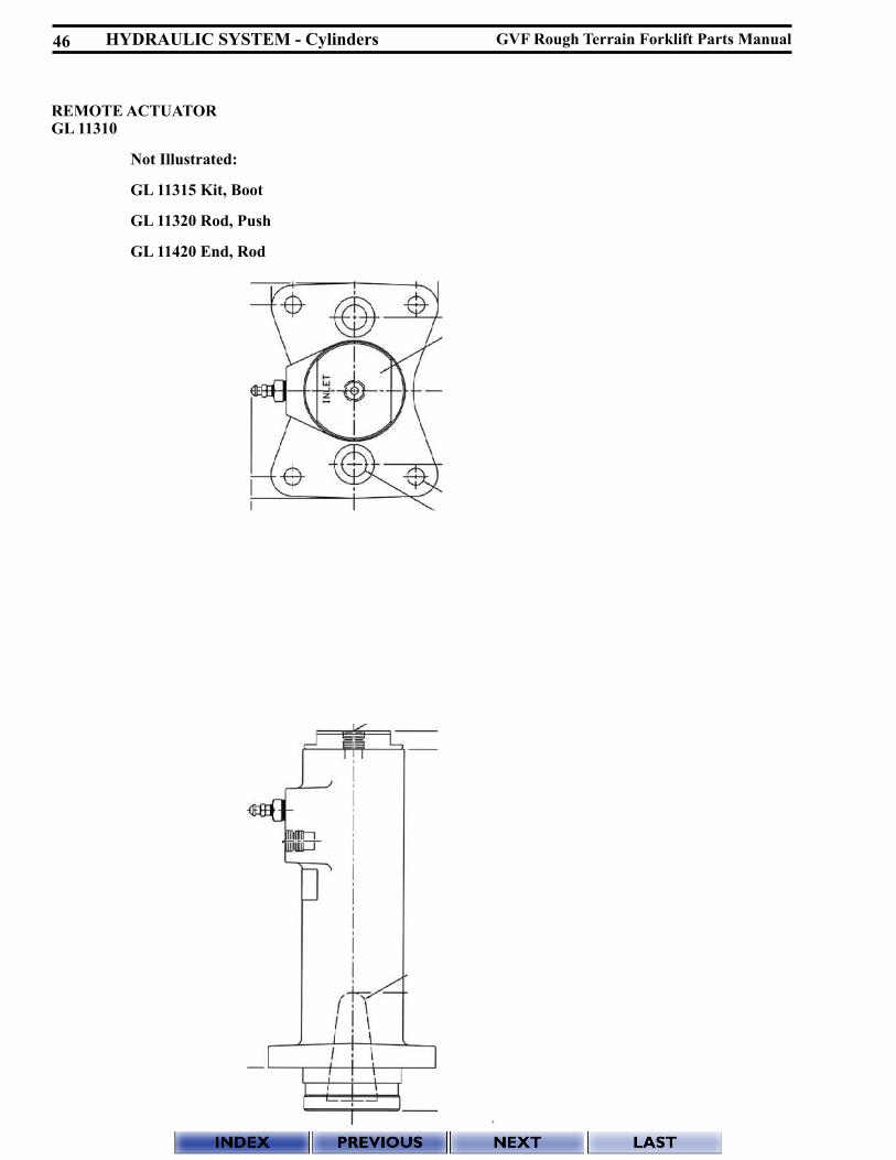
REMOTE ACTUATOR GL 11310
Not Illustrated:
GL 11315 Kit, Boot
GL 11320 Rod, Push
GL 11420 End, Rod

HYDRAULIC SYSTEM - Oil Tank 47GVF Rough Terrain Forklift Parts Manual
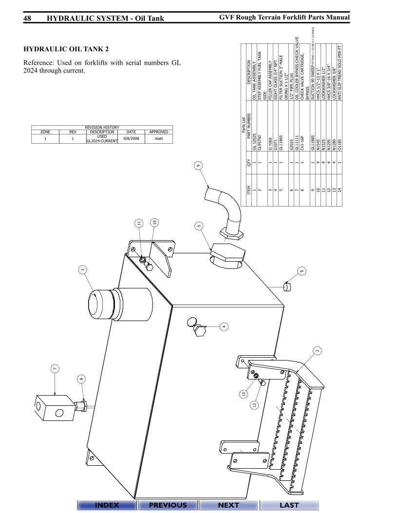
HYDRAULIC OIL TANK 1
Reference: Used on forklifts with serial numbers GL 2000 through GL 2023.
1 1
2 2
3 3
4 4
AA
BB
CC
DD
SHEE
T 1
OF
1
DR
AWN
CHEC
KED
QA
MFG
APPR
OVE
D
mat
t9/
11/2
008
DW
G N
O
GL9
570P
TITL
E
HYD
RAU
LIC
OIL
TAN
K
SIZE C
SCAL
E
GIL
LISO
N'S
VAR
IETY
FAB
.
REV
Part
s Li
stD
ESCR
IPTI
ON
PART
NU
MBE
RQ
TYIT
EMO
IL T
ANK
BACK
GL9
570
11
3" O
.D. S
TAIN
LESS
TU
BIN
GG
L957
31
2FI
LTER
SU
CTIO
N 3
" X
1 1/
2" N
PTG
SS10
516
13
SIG
HT
GLA
SS 3
/4"
NPT
G10
711
41/
2" P
IPE
PLU
GG
2010
15
OIL
CO
OLE
R BY
PASS
VAL
VEG
L111
111
63/
4" P
IPE
PLU
GX1
060
17
FILL
ER C
AP A
SSEM
BLY
G10
661
8AI
R P
RECL
ENER
EX-
30G
L112
051
9H
HCS
3/8
"-16
X 3
/4"
N12
952
10LO
CKW
ASH
ER 3
/8"
N12
803
11FL
ATW
ASH
ER 3
/8"
N12
753
12FH
CS 1
0-24
X 3
/4"
SSN
9775
313
NU
T 10
-24
N94
153
14TA
NK
EXPA
NSI
ON
GL1
28-1
5313
115
FILT
ER A
SSY,
FU
ELG
L320
-071
401
16FI
LTER
/WAT
ER T
RAP
GL1
1675
117
HH
CS 3
/8"-
16 X
1"
N13
001
18H
HCS
5/1
6"-1
8 X
3/4"
N11
651
19FL
ATW
ASH
ER 5
/16"
N11
451
20LO
CKW
ASH
ER 5
/16"
N11
501
21CA
P, E
NPA
NSI
ON
TAN
KG
L477
-002
231
22FI
TTIN
G 2
4 H
OSE
BARB
-24
N
PTG
SS11
055
123
ADAP
TOR,
3-3
STR
AIG
HT
HU
MP
OP1
0560
81
24
CLAM
P, T
BO
LT T
BC35
0O
1415
225
CLAM
P, T
BO
LT T
BC20
0O
1417
226
HIN
GE
(NO
T IL
LIST
RAT
ED)
GH
1185
74
27
1811
12
5
3
16
12
1110
6
13
2
9
1921
204
REVI
SIO
N H
ISTO
RYZO
NE
REV
DES
CRIP
TIO
ND
ATE
APPR
OVE
D
11
USE
DG
L200
0-G
L202
39/
11/2
008
mat
t
22
25
26
23
15
24
14 1
STA
INLE
SS
INTA
KE
CH
EC
K V
ALV
EB
LK P
IPE
PLU
G
PR
EC
LEA
NE
R E
X -3
0G
106
5
MA
CH
INE
SC
RE
W 1
0-24
X 3
/4” S
S
FILT
ER
, FU
EL/
WAT
ER
TR
AP
EX
PAN
SIO
N
LATC
H (N
OT
ILLU
STR
ATE
D)
GL
1252
0A
SS
EM
BLY
HYDRAULIC SYSTEM - Oil Tank48 GVF Rough Terrain Forklift Parts Manual1 1
2 2
3 3
4 4
AA
BB
CC
DD
SHEE
T 1
OF
1
DR
AWN
CHEC
KED
QA
MFG
APPR
OVE
D
mat
t2/
27/2
008
DW
G N
O
GL9
5740
-2
TITL
E
OIL
TAN
K PA
RTS
BREA
KDO
WN
SIZE C
SCAL
E
GIL
LISO
N'S
VAR
IETY
FAB
.
REV
Part
s Li
stD
ESCR
IPTI
ON
PAR
T N
UM
BER
QTY
ITEM
OIL
TAN
KG
L957
401
1ST
EP A
SSEM
BLY
FUEL
TAN
K SI
DE
GL9
5750
12
FILL
ER C
AP A
SSEM
BLY
G10
661
3SI
GH
T G
LASS
3/4
" N
PTG
1071
14
FILT
ER S
UCT
ION
3"
MAL
E O
RIN
G X
1 1
/2"
GL1
1865
15
1/2"
PIP
E PL
UG
G20
101
6O
IL C
OO
LER
BYPA
SSG
L111
111
7CH
ECK
VALV
E CA
RTRI
DG
E,
BYPA
SSCV
1-16
P1
8
SUCT
ION
90
SWEE
PG
L118
851
9H
HCS
1/2
"-13
X 1
"N
1545
410
LOCK
WAS
HER
1/2
"N
1525
411
HH
CS 3
/8"-
16 X
3/4
"N
1295
412
LOCK
WAS
HER
3/8
"N
1280
413
ANTI
SLI
P TR
EAD
SO
LD P
ER-F
TO
1185
114
7
83
59
6
4
2
11 10
12
13
REV
ISIO
N H
ISTO
RY
ZON
ERE
VD
ESCR
IPTI
ON
DAT
EAP
PRO
VED
11
USE
DG
L202
4-CU
RRE
NT
9/8/
2008
mat
t
1
1
2
2
3
3
4
4
A A
B B
C C
D D
SHEET 1 OF 1
DRAWN
CHECKED
QA
MFG
APPROVED
matt 2/27/2008
DWG NO
GL95740-2
TITLE
OIL TANK PARTS BREAKDOWN
SIZE
CSCALE
GILLISON'S VARIETY FAB.
REV
Parts ListDESCRIPTIONPART NUMBERQTYITEM
OIL TANKGL9574011STEP ASSEMBLY FUEL TANK SIDE
GL9575012
FILLER CAP ASSEMBLYG106613SIGHT GLASS 3/4" NPTG107114FILTER SUCTION 3" MALE ORING X 1 1/2"
GL1186515
1/2" PIPE PLUGG201016OIL COOLER BYPASSGL1111117CHECK VALVE CARTRIDGE, BYPASS
CV1-16P18
SUCTION 90 SWEEPGL1188519HHCS 1/2"-13 X 1"N1545410LOCKWASHER 1/2"N1525411HHCS 3/8"-16 X 3/4"N1295412LOCKWASHER 3/8"N1280413ANTI SLIP TREAD SOLD PER-FTO1185114
7
8 3
5 9
6
4
2
11
10
12
13
REVISION HISTORYZONE REV DESCRIPTION DATE APPROVED
1 1 USEDGL2024-CURRENT
9/8/2008 matt
GL
1252
5
G 1
065
CH
EC
K V
ALV
E
FITT
ING
1 1
/2 H
B X
1 1
/2 M
ALE
AS
SE
MB
LY
HYDRAULIC OIL TANK 2
Reference: Used on forklifts with serial numbers GL 2024 through current.
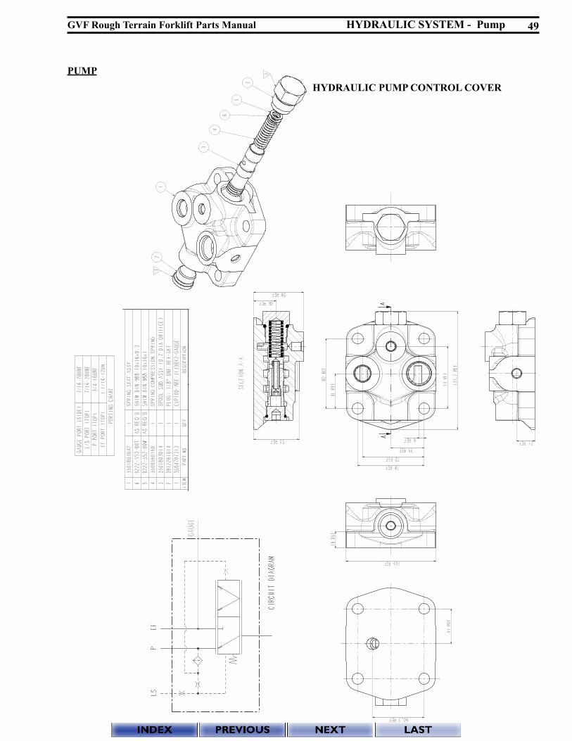
HYDRAULIC SYSTEM - Pump 49GVF Rough Terrain Forklift Parts Manual
PUMPHYDRAULIC PUMP CONTROL COVER

HYDRAULIC SYSTEM - Pump50 GVF Rough Terrain Forklift Parts Manual
EX
PN
O.
FIR
ST
US
ED
SY
M.
REV
ISIO
NS
702
9112
087
07-0
8-40
05
GE
AR
132
0-08
031
26SE
CTI
ON
SE
AL
193
12-6
41-0
0425
WA
SH
ER
892
22-5
75-0
0924
SEA
L,LI
P2
8682
-119
-00W
23BA
LAN
CE
PLA
TE2
8682
-058
-00M
22BU
SH
ING
486
82-0
18-0
0C21
SEA
L,E
NE
RG
.2
8682
-016
-00L
20SE
AL,
ELE
M.
286
82-0
15-0
0Q19
TAB
WA
SH
ER
186
82-0
10-0
0F18
STU
D4
8682
-007
-00M
17SE
AL,
O-R
139
128
8250
315
SEA
L,O
-R1
391
2882
499
14O
-RIN
G,-
022
139
128
8144
413
RIN
G,S
NAP
139
126
8600
812
NA
ME
PLA
TE1
391
2183
227
11KE
Y.7
5DIA
.WO
OD
RU
FF1
391
1781
095
10N
UT,
HE
X1
391
1451
243
9N
UT,
HE
X4
391
1451
149
8SC
RE
W,D
RIV
E2
391
1432
004
7C
AP
SC
RE
W(4
0mm
)4
391
1401
779
6C
VP
100-
AB
F-J1
J3X
B2
135
097
1308
05
DR
IVE
GE
AR-S
HA
FT1
702
1833
802
4G
EA
R,D
RIV
EN
170
227
3300
03
BOD
Y1
702
7933
010
2FL
AN
GE
177
020:
4118
583
1D
ESC
RIP
TIO
NQ
TYPA
RT
NU
MB
ER
ITE
M
2"S
PLI
TFL
AN
GE
RE
DU
CE
DTO
38.0
46.0
x25
DE
EP
C'B
OR
E1/
2"-1
3U
NC
-2B
THD
18.0
DE
EP
-4H
OLE
S
CC
WR
OTA
TIO
N
NO
TE: FO
RA
SSE
MBL
YIN
STR
UC
TIO
NS
SE
ED
WG
.NO
."62
0-B
1""P
GP
620
PUM
PA
SS
EM
BLY
INS
TRU
CTI
ON
S."
C
THIS
DO
CU
MEN
TC
ON
TAIN
SIN
FOR
MAT
ION
THAT
ISC
ON
FID
ENTI
ALA
ND
PRO
PR
IETA
RY
TOPA
RKE
R-H
ANN
IFIN
CO
RPO
RAT
ION
("P
ARKE
R")
.TH
ISD
OC
UM
EN
TIS
FUR
NIS
HE
DO
NTH
EU
ND
ERST
AN
DIN
GTH
ATTH
ED
OC
UM
EN
TA
ND
THE
INFO
RM
ATI
ON
ITC
ON
TAIN
SW
ILL
NO
TB
EC
OPI
ED
OR
DIS
CLO
SE
DTO
OTH
ERS
OR
US
ED
FOR
ANY
PUR
PO
SE
OTH
ER
THA
NC
ON
DU
CTI
NG
BU
SIN
ESS
WIT
HP
AR
KER
,AN
DW
ILL
BER
ETU
RN
ED
AN
DAL
LFU
RTH
ER
US
ED
ISC
ON
TIN
UED
UPO
NR
EQ
UES
TBY
PAR
KER
.A
LLR
IGH
TSR
ESE
RV
ED
.
MA
TER
IAL
H.E
.-STD
:
AD
MC
TR
RE
VD
TE WT.
DR
.BY
DA
TEC
H.B
YD
ATE
Hyd
raul
ics
Par
ker-
Han
nifin
Cor
p.G
earP
ump
Div
isio
nY
oung
stow
n,O
H44
501
US
A
PG
P62
0A03
30A
T2K
5WS7
B1L
YBK
*P
0000
00
36.3
TLE
10A
ug07
RA
G15
Aug0
7
702
9112
087
2007
Par
ker-
Han
nifin
Cor
pora
tion
WIT
HTH
EE
XC
EP
TIO
NO
FD
RIV
ES
HA
FT,
FLAN
GE
SP
IGO
TA
ND
MTG
.FA
CE
PLU
SA
REA
SA
RO
UN
DP
OR
TS,A
LLSU
RFA
CE
SA
RE
PA
INTE
DB
LAC
KZS
S-A
1(A
A-O
-05.
2)To
lera
nces
Unl
ess
Oth
erw
ise
Spe
cifie
d
}=
Ref
.D
IME
NS
ION
S
DIM
EN
SIO
NS
AR
Em
mW
EIG
HT
ISLB
S
151.
1
711
1225
2220
19
2121
1
139.
158
.0
5
817
33.0
33.0
11/
16"-
12S
TR.T
HD
.FO
R3/
4"O
.D.T
UB
ES
EC
ON
DA
RY
PO
RT
(EF)
3/4"
-16
STR
.TH
D.F
OR
1/2"
O.D
.TU
BE
PR
IMA
RY
POR
T(C
F)
SH
AFT
PO
RTS
THIR
DAN
GLE
PROJ
ECTI
ON
TES
TP
UM
PP
ERTE
ST
SPE
C'S
SAM
ED
WG
.NO
.
G
PE
FLS
PUM
P
3
6
15 13
73.0
014
6.00
176.
2M
AX
121.
014
.32
HO
LES
7.0
14.5
98.1
160.
1
5.0
50.8
197.
1
20.3
50.8
MAX
73
142.
2M
AX
12
24
13.0
101.
6- 0
.25
PIL
OT
24
32.0
7/16
"-20
STR
.TH
D.F
OR
1/4"
O.D
.TU
BE
GA
UG
EP
OR
T(G
)
7/16
"-20
STR
.TH
D.F
OR
1/4"
O.D
.TU
BE
LOA
DS
EN
SIN
GP
OR
T(L
S)
2323
10
26
4
18
2.4
M16
x1.5
THD
15.0
33.0
GA
UG
ELI
NE
23.8
GA
UG
E
TAPE
R1:
510
WO
OD
RU
FFK
EY
5.0
x7.
5D
IN68
88
PU
MP
SW
ITH
LOA
DS
EN
SIN
GP
RIO
RIT
YV
ALV
EA
ND
DY
NA
MIC
LOA
DS
EN
SIN
GS
IGN
AL
MA
XP
RE
SS
UR
EA
TPR
IOR
ITY
VALV
E:
220
BA
R(3
191
PS
I)M
AX
PR
ES
SU
RE
AT
EXC
ESS
PO
RT
(EF)
:26
0B
AR
(377
1PS
I)C
ON
TRO
LP
RE
SS
UR
E:
20B
AR
(190
PS
I)
PTO
GE
AR
41T
-HC
R32
0/08
031
14HYDRAULIC PUMPGL475/M1078

MATERIAL HANDLING SYSTEM - Bin Clamp 51GVF Rough Terrain Forklift Parts Manual
MATERIAL HANDLING SYSTEM
BIN CLAMP
1 1
2 2
3 3
4 4
AA
BB
CC
DD
SHEE
T 1
OF
1
DR
AWN
CHEC
KED
QA
MFG
APPR
OVE
D
mat
t2/
25/2
008
DW
G N
O
GL9
6000
_1
TITL
E
BIN
CLA
MP
PART
S
SIZE C
SCAL
E
GIL
LISO
N'S
VAR
IETY
FAB
.
REV
Part
s Li
stD
ESCR
IPTI
ON
PART
NU
MBE
RQ
TYIT
EMBI
N C
LAM
P SL
IDE
TUBE
CY
L. M
T AS
SEM
BLY
GL9
6015
11
SLID
E TU
BE A
SSEM
BLY
GL9
6005
22
TOP
CLAM
P AS
SEM
BLY
GL9
6013
13
RUBB
ER P
ADS
8"-
1/4"
-2PL
Y RU
BBER
GL9
6027
34
HH
CS 1
/2"-
13 X
1 1
/2"
N15
5014
5LO
CKW
ASH
ER 1
/2"
N15
2522
6H
EX N
UT
1/2"
13N
1515
127
ELEV
ATO
R BO
LT 1
/4"-
20 X
1
1/4"
N80
4012
8
HEX
NU
T 1/
4"-2
0N
1010
129
LOCK
WAS
HER
1/4
"N
1020
1210
HH
CS 1
/2"-
13 X
1 3
/4"
N15
524
111
1/4"
X 4
" CO
LD F
LAT
CLAM
P SU
PPO
RTG
L950
254
12
CLAM
P 1/
2" X
1 1
/2"
GL9
6026
413
HEX
NU
T 5/
8"-1
1N
1625
214
LOCK
WAS
HER
5/8
"N
1635
215
HH
CS 5
/8"-
11 X
1 1
/2"
N16
652
16H
HCS
1/2
"-13
X 1
1/2
"N
1557
417
16M
M L
OCK
WAS
HER
N34
604
18H
HCS
16M
M -
2.0
X 50
MM
G
R 10
.9N
3479
419
FLAT
WAS
HER
1/2
"N
1520
220
1/4"
-28
GR
EASE
FIT
TIN
G
STRA
IGH
TD
2004
421
4
12
17
5
6
19
18
14
1516
2
5
810
9
5
6
20
3
1
21
2 1/
4”2
”
SHO
RT
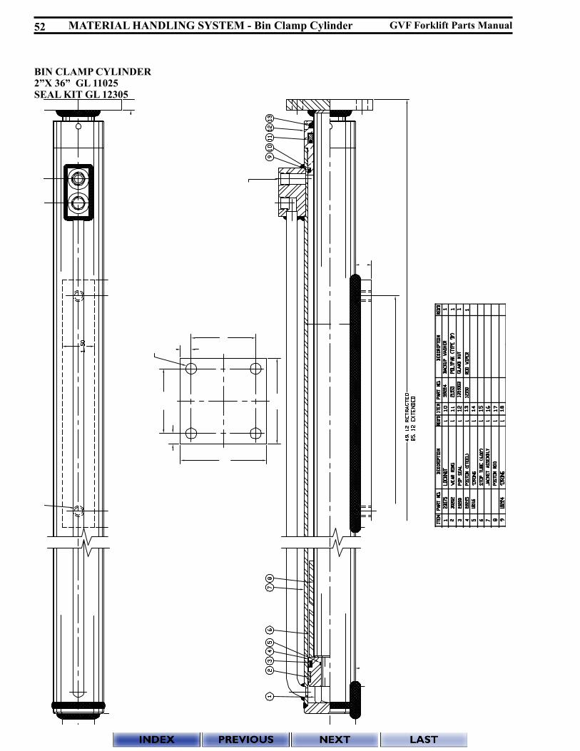
MATERIAL HANDLING SYSTEM - Bin Clamp Cylinder52 GVF Forklift Parts Manual
BIN CLAMP CYLINDER2”X 36” GL 11025 SEAL KIT GL 12305
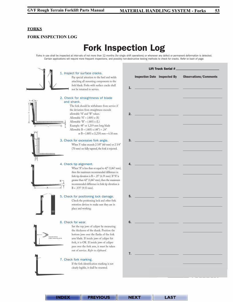
MATERIAL HANDLING SYSTEM - Forks 53GVF Rough Terrain Forklift Parts Manual
Fork Inspection LogForks in use shall be inspected at intervals of not more than 12 months (for single shift operations) or whenever any defect or permanent deformation is detected.
Certain applications will require more frequent inspections, and possibly non-destructive testing methods to check for cracks. Refer to back of page.
Inspection Date Inspected By Observations/Comments
B
A
S
L
2"
Y
21"
1. Inspect for surface cracks.Pay special attention to the heel and weldsattaching all mounting components to thefork blank. Forks with surface cracks shallnot be returned to service.
2. Check for straightness of bladeand shank.
The fork should be withdrawn from service ifthe deviation from straightness exceedsallowable “A” and “B” values.Allowable “A” = (.005) x (S)Allowable “B” = (.005) x (L)Example: 48" or 1,219 mm long bladeAllowable B = (.005) x (48") = .24"
or B = (.005) x (1,219) mm = 6.10 mm
B
A
4. Check tip alignment.When “A” is less than or equal to 42" (1,067 mm),then the maximum recommended difference infork tip elevation is B = .25" (6.35 mm). If “A” isgreater than 42" (1,067 mm), then the maximumrecommended difference in fork tip elevation isB = .375" (9.53 mm).
Cascade Kenhar caliper measuring points.
5. Check for positioning lock damage.Check the positioning lock and other forkretention devices to make sure they are inplace and working.
6. Check for wear.Set the top jaws of caliper by measuringthe thickness of the shank. Position thebottom jaws over the flanks of the forkarm blade. If inside jaws of caliper hitfork, it is OK. If inside jaws of caliperpass over the fork arm, it must be takenout of service. Refer to clipboard.
7. Check fork marking.If the fork identification marking is notclearly legible, it shall be renewed.
3. Check for excessive fork angle.When Y value exceeds 2 3/8" (60 mm) or 2 3/4"(70 mm) on fully tapered, the fork is rejected.
Lift Truck Serial #
1.
2.
3.
4.
5.
6.
7.
FORKS
FORK INSPECTION LOG
MATERIAL HANDLING SYSTEM - Forks54 GVF Rough Terrain Forklift Parts Manual
Reprinted from ASME/ANSI B56. 1-20006.2.8 Inspection and Repair of Forks in Service on ForkLift Trucks
(a) Forks in use shall be inspected at intervals of notmore than 12 months (for single shift operations) orwhenever any defect or permanent deformation is detected.Several applications will require more frequent inspection.
(b) Individual and Load Rating of Forks. Whenforks are used in pairs (the normal arrangement), therated capacity of each fork shall be at least half of themanufacturer’s rated capacity of the truck, and at the ratedload center distance shown on the lift truck nameplate.
6.2.8.1 Inspection. Fork inspections shall be carriedout carefully by trained personnel with the aim of detect-ing any damage, failure, deformation, etc., which mightimpair safe use. Any fork which shows such a defect shallbe withdrawn from service, and shall not be returned toservice unless it has been satisfactorily repaired in accor-dance with para 6.2.8.2.
(a) Surface Cracks. The fork shall be thoroughlyexamined visually for cracks and if considered necessary,subjected to a non-destructive crack detection process,special attention being paid to the heel and welds attachingall mounting components to the fork blank. This inspectionfor cracks must also include any special mountingmechanisms of the fork blank to the fork carrier includingbolt type mountings and forged upper mountingarrangements for hook or shaft type carriages. The forksshall not be returned to service if surface cracks are detected.
(b) Straightness of Blade and Shank. The straightnessof the upper face of the blade and the front face of the shankshall be checked. If the deviation from straightness exceeds0.5% of the length of the blade and/or the height of theshank, respectively, the fork shall not be returned to serviceuntil it has been repaired in accordance with para 6.2.8.2.
(c) Fork Angle (Upper Face of Blade to Load of theShank). Any fork that has a deviation of greater than 3deg. from the original specification shall not be returnedto service. The rejected fork shall be reset and tested inaccordance with para 6.2.8.2.
(d) Difference in Height of Fork Tips. The differencein height of one set of forks when mounted on the fork
carrier shall be checked. If the difference in tip heightsexceeds 3% of the length of the blade, the set of forksshall not be returned to service until repaired in accor-dance with para 6.2.8.2.
(e) Positioning Lock (Where Originally Provided).It shall be confirmed that the positioning lock is in goodrepair and correct working order. If any fault is found, thefork shall be withdrawn from service until satisfactoryrepair has been effected.
(f ) Wear(1) Fork Blade and Shank. The fork blade and
shank shall be thoroughly checked for wear,special attention being paid to the vicinity ofthe heel. If the thickness is reduced to 90% ofthe original thickness, the fork shall not bereturned to service.
(2) Fork Hooks (Where Originally Provided).The support face of the top hook and theretaining faces of both hooks shall be checkedfor wear, crushing, and other local deforma-tions. If these are apparent to such an extentthat the clearance between the fork and thefork carrier becomes excessive, the fork shallnot be returned to service until repaired inaccordance with para 6.2.8.2.
(g) Legibility of Marking (When OriginallyProvided). If the fork marking in accordance with para7.25.2 is not clearly legible, it shall be renewed. Markingshall be renewed per instructions from original supplier.
6.2.8.2. Repair and Testing(a) Repair. Only the manufacturer of the fork or an
expert of equal competence shall decide if a fork may berepaired for continual use, and the repairs shall only becarried out by such parties. It is not recommended thatsurface cracks or wear be repaired by welding. Whenrepairs necessitating resetting are required, the fork shallsubsequently be subjected to an appropriate heat treat-ment, as necessary.
USER FORK WEAR STANDARDS
Courtesy of
For additional Fork Inspection Kits (poster, clipboard, inspection log and caliper) call your lift truck dealer.© 2003 Cascade Corporation. All rights reserved. Cascade and Kenhar are trademarks of Cascade Corporation. Form #3014165. To reorder call 888 CASCADE (227-2233).
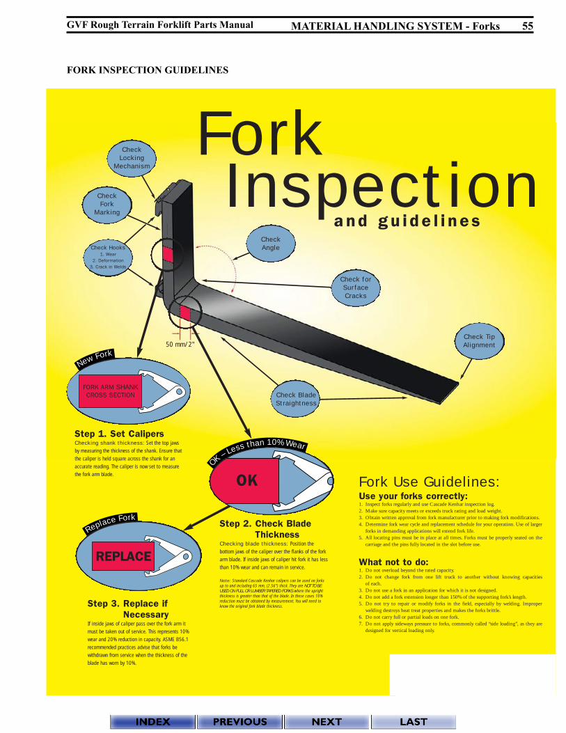
MATERIAL HANDLING SYSTEM - Forks 55GVF Rough Terrain Forklift Parts Manual
Replace Fork
OK – Less than 10% Wear
New Fork
ForkInspection
a n d g u i d e l i n e s
Step 1. Set CalipersChecking shank thickness: Set the top jaws
by measuring the thickness of the shank. Ensure that
the caliper is held square across the shank for an
accurate reading. The caliper is now set to measure
the fork arm blade.
50 mm/2"
Step 2. Check BladeThickness
Checking blade thickness: Position the
bottom jaws of the caliper over the flanks of the fork
arm blade. If inside jaws of caliper hit fork it has less
than 10% wear and can remain in service.
Note: Standard Cascade Kenhar calipers can be used on forksup to and including 65 mm, (2.56") thick. They are NOT TO BEUSED ON FULL OR LUMBER TAPERED FORKS where the uprightthickness is greater than that of the blade. In these cases 10%reduction must be obtained by measurement. You will need toknow the original fork blade thickness.Step 3. Replace if
NecessaryIf inside jaws of caliper pass over the fork arm it
must be taken out of service. This represents 10%
wear and 20% reduction in capacity. ASME B56.1
recommended practices advise that forks be
withdrawn from service when the thickness of the
blade has worn by 10%.
CheckLocking
Mechanism
CheckFork
Marking
Check Hooks1. Wear
2. Deformation3. Crack in Welds
Capacity at load center.
CheckAngle
Check forSurfaceCracks
Check TipAlignment
Check BladeStraightness
Use your forks correctly:1. Inspect forks regularly and use Cascade Kenhar inspection log.2. Make sure capacity meets or exceeds truck rating and load weight.3. Obtain written approval from fork manufacturer prior to making fork modifications.4. Determine fork wear cycle and replacement schedule for your operation. Use of larger
forks in demanding applications will extend fork life.5. All locating pins must be in place at all times. Forks must be properly seated on the
carriage and the pins fully located in the slot before use.
What not to do:1. Do not overload beyond the rated capacity.2. Do not change fork from one lift truck to another without knowing capacities
of each.3. Do not use a fork in an application for which it is not designed.4. Do not add a fork extension longer than 150% of the supporting fork’s length.5. Do not try to repair or modify forks in the field, especially by welding. Improper
welding destroys heat treat properties and makes the forks brittle.6. Do not carry full or partial loads on one fork.7. Do not apply sideways pressure to forks, commonly called “side loading”, as they are
designed for vertical loading only.
Fork Use Guidelines:
FORK ARM SHANKCROSS SECTION
OK
REPLACE
For additional Fork Inspection Kits (poster, clipboard, inspection log and caliper) call your lift truck dealer.© 1999 Cascade Corporation. All rights reserved. Cascade and Kenhar are trademarks of Cascade Corporation. Form #3014163. To reorder call 888 CASCADE (227-2233).
FORK INSPECTION GUIDELINES
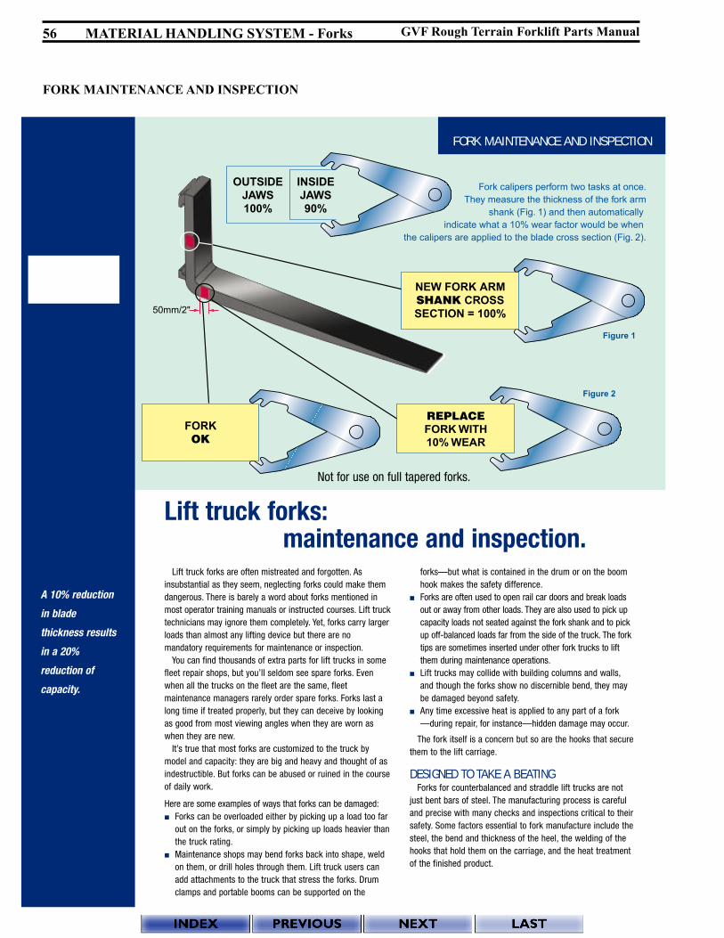
MATERIAL HANDLING SYSTEM - Forks56 GVF Rough Terrain Forklift Parts Manual
Lift truck forks are often mistreated and forgotten. Asinsubstantial as they seem, neglecting forks could make themdangerous. There is barely a word about forks mentioned inmost operator training manuals or instructed courses. Lift trucktechnicians may ignore them completely. Yet, forks carry largerloads than almost any lifting device but there are nomandatory requirements for maintenance or inspection.
You can find thousands of extra parts for lift trucks in somefleet repair shops, but you’ll seldom see spare forks. Evenwhen all the trucks on the fleet are the same, fleetmaintenance managers rarely order spare forks. Forks last along time if treated properly, but they can deceive by lookingas good from most viewing angles when they are worn aswhen they are new.
It’s true that most forks are customized to the truck bymodel and capacity: they are big and heavy and thought of asindestructible. But forks can be abused or ruined in the courseof daily work.
Here are some examples of ways that forks can be damaged:■ Forks can be overloaded either by picking up a load too far
out on the forks, or simply by picking up loads heavier thanthe truck rating.
■ Maintenance shops may bend forks back into shape, weldon them, or drill holes through them. Lift truck users canadd attachments to the truck that stress the forks. Drumclamps and portable booms can be supported on the
forks—but what is contained in the drum or on the boomhook makes the safety difference.
■ Forks are often used to open rail car doors and break loadsout or away from other loads. They are also used to pick upcapacity loads not seated against the fork shank and to pickup off-balanced loads far from the side of the truck. The forktips are sometimes inserted under other fork trucks to liftthem during maintenance operations.
■ Lift trucks may collide with building columns and walls,and though the forks show no discernible bend, they maybe damaged beyond safety.
■ Any time excessive heat is applied to any part of a fork—during repair, for instance—hidden damage may occur.
The fork itself is a concern but so are the hooks that securethem to the lift carriage.
DESIGNED TO TAKE A BEATINGForks for counterbalanced and straddle lift trucks are not
just bent bars of steel. The manufacturing process is carefuland precise with many checks and inspections critical to theirsafety. Some factors essential to fork manufacture include the steel, the bend and thickness of the heel, the welding of thehooks that hold them on the carriage, and the heat treatmentof the finished product.
INSIDEJAWS90%
OUTSIDEJAWS100%
NEW FORK ARMSHANK CROSSSECTION = 100%
Figure 1
Figure 2
Fork calipers perform two tasks at once.They measure the thickness of the fork arm
shank (Fig. 1) and then automatically indicate what a 10% wear factor would be when
the calipers are applied to the blade cross section (Fig. 2).
50mm/2"
REPLACEFORK WITH10% WEAR
FORKOK
FORK MAINTENANCE AND INSPECTION
Lift truck forks:maintenance and inspection.
A 10% reduction
in blade
thickness results
in a 20%
reduction of
capacity.
Not for use on full tapered forks.
FORK MAINTENANCE AND INSPECTION
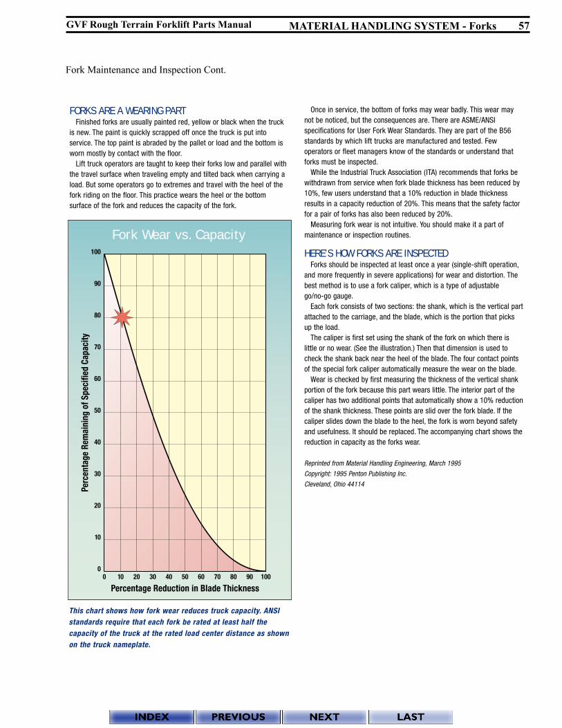
MATERIAL HANDLING SYSTEM - Forks 57GVF Rough Terrain Forklift Parts Manual
FORK MAINTENANCE AND INSPECTION
FORKS ARE A WEARING PARTFinished forks are usually painted red, yellow or black when the truck
is new. The paint is quickly scrapped off once the truck is put intoservice. The top paint is abraded by the pallet or load and the bottom isworn mostly by contact with the floor.
Lift truck operators are taught to keep their forks low and parallel withthe travel surface when traveling empty and tilted back when carrying aload. But some operators go to extremes and travel with the heel of thefork riding on the floor. This practice wears the heel or the bottomsurface of the fork and reduces the capacity of the fork.
Once in service, the bottom of forks may wear badly. This wear maynot be noticed, but the consequences are. There are ASME/ANSIspecifications for User Fork Wear Standards. They are part of the B56standards by which lift trucks are manufactured and tested. Fewoperators or fleet managers know of the standards or understand thatforks must be inspected.
While the Industrial Truck Association (ITA) recommends that forks bewithdrawn from service when fork blade thickness has been reduced by10%, few users understand that a 10% reduction in blade thicknessresults in a capacity reduction of 20%. This means that the safety factorfor a pair of forks has also been reduced by 20%.
Measuring fork wear is not intuitive. You should make it a part ofmaintenance or inspection routines.
HERE’S HOW FORKS ARE INSPECTEDForks should be inspected at least once a year (single-shift operation,
and more frequently in severe applications) for wear and distortion. Thebest method is to use a fork caliper, which is a type of adjustable go/no-go gauge.
Each fork consists of two sections: the shank, which is the vertical partattached to the carriage, and the blade, which is the portion that picksup the load.
The caliper is first set using the shank of the fork on which there islittle or no wear. (See the illustration.) Then that dimension is used tocheck the shank back near the heel of the blade. The four contact pointsof the special fork caliper automatically measure the wear on the blade.
Wear is checked by first measuring the thickness of the vertical shankportion of the fork because this part wears little. The interior part of thecaliper has two additional points that automatically show a 10% reductionof the shank thickness. These points are slid over the fork blade. If thecaliper slides down the blade to the heel, the fork is worn beyond safetyand usefulness. It should be replaced. The accompanying chart shows thereduction in capacity as the forks wear.
Reprinted from Material Handling Engineering, March 1995
Copyright: 1995 Penton Publishing Inc.
Cleveland, Ohio 44114
00 10 20 30 40 50
Percentage Reduction in Blade Thickness
Perc
enta
ge R
emai
ning
of S
peci
fied
Capa
city
60 70 80 90 100
10
20
30
40
60
50
70
80
90
100
Fork Wear vs. Capacity
This chart shows how fork wear reduces truck capacity. ANSIstandards require that each fork be rated at least half thecapacity of the truck at the rated load center distance as shownon the truck nameplate.
PO Box 20187 • Portland, OR 97294-0187 • 800.426.7708 • Tel 503.669.6300 • Fax 503.669.6247 • www.cascorp.comP.O. Box 1508 • Guelph, Ontario, Canada N1H 6N9 • 877 CASCADE (227.2233) • Fax: 519.763.1472
Form 222286 R1 10M PG 12/00
Cascade is a registered trademark of Cascade Corporation.
© Cascade Corporation 2000. All rights reserved.
Fork Maintenance and Inspection Cont.

MATERIAL HANDLING SYSTEM - Forks58 GVF Rough Terrain Forklift Parts Manual
FORKS100X45X1219 GL 11285
GL 11285, Forks
GL 7000031,
Class 11 Pin Lit
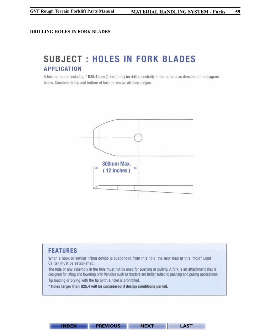
MATERIAL HANDLING SYSTEM - Forks 59GVF Rough Terrain Forklift Parts Manual
DRILLING HOLES IN FORK BLADES
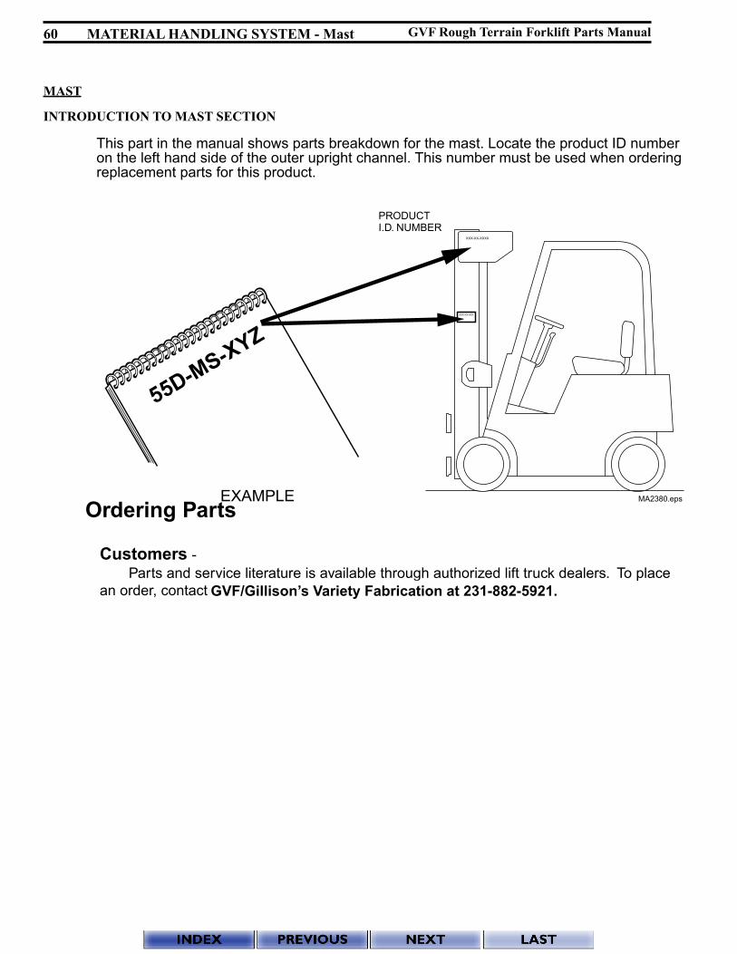
MATERIAL HANDLING SYSTEM - Mast60 GVF Rough Terrain Forklift Parts Manual
MAST
INTRODUCTION TO MAST SECTION
PRODUCT I.D. NUMBER
XXX-XX-XXX
MA2380.epsEXAMPLE
XXX-XX-XXXX
About This Manual
Introduction
LIFT-TEK / ELECARCUSTOMER SERVICE7040 S HWY 11
WESTMINSTER, S.C. 29693TELEPHONE: (888) 946-3330
FAX: (864) 647-6195
This manual shows the parts breakdown for the mast product ID numbers. Locate the productID number on the left hand side of the outer upright channel. This number must be used whenordering replacement parts for this product.
Ordering Parts
Customers -Parts and service literature is available through authorized lift truck dealers. To place
an order, contact the lift truck dealer of your choice.
Lift Truck Dealers -To order parts and service literature contact:
55D-MS-XYZ
GVF/Gillison’s Variety Fabrication at 231-882-5921.
This part in the manual shows parts breakdown for the mast. Locate the product ID number on the left hand side of the outer upright channel. This number must be used when ordering replacement parts for this product.
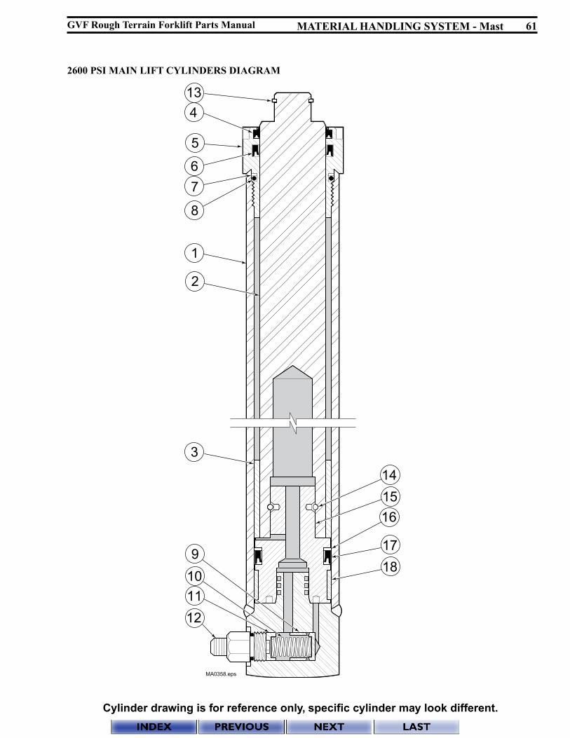
MATERIAL HANDLING SYSTEM - Mast 61GVF Rough Terrain Forklift Parts Manual
PRODUCT I.D. NUMBER
XXX-XX-XXX
MA2380.epsEXAMPLE
XXX-XX-XXXX
About This Manual
Introduction
LIFT-TEK / ELECARCUSTOMER SERVICE7040 S HWY 11
WESTMINSTER, S.C. 29693TELEPHONE: (888) 946-3330
FAX: (864) 647-6195
This manual shows the parts breakdown for the mast product ID numbers. Locate the productID number on the left hand side of the outer upright channel. This number must be used whenordering replacement parts for this product.
Ordering Parts
Customers -Parts and service literature is available through authorized lift truck dealers. To place
an order, contact the lift truck dealer of your choice.
Lift Truck Dealers -To order parts and service literature contact:
55D-MS-XYZ
6
2600 PSI Main Lift Cylinders
5
67
8
2
1
413
3
9101112
141516
1817
MA0358.eps
Cylinder drawing is for reference only, specific cylinder may look different.
2600 PSI MAIN LIFT CYLINDERS DIAGRAM

MATERIAL HANDLING SYSTEM - Mast62 GVF Rough Terrain Forklift Parts Manual
7
2600 PSI Main Lift Cylinders
Item QTY Part # Description Item QTY Part # Description1 1 N/A Shell Assembly 10 1 562847 Fuse Spring2 1 N/A Plunger 11 1 562848 Spring Guide3 1 N/A Spacer 12 1 684036 Fitting4 1 1 Plunger Wiper 13 1 3129 Snap Ring5 1 562630 Retainer 14 1 1 , 2 Pull Wire6 1 1 U-Cup Seal 15 1 2 Piston7 1 1 Backup Ring 16 1 1 Nylon Ring8 1 1 O-Ring 17 1 1 , 2 Piston Seal9 1 563782 Fuse Piston 18 1 1 , 2 Wear Ring
1 - Included in Seal Kit P/N 562591.2 - Included in Piston Service Kit P/N 561244.
HPML-2
OCL HIGH PRESSURE
OCL HIGH PRESSURE
OCL HIGH PRESSURE
MAINLIFT MAINLIFT MAINLIFTREF A REF A REF A
(in) QTY 2 (in) QTY 2 (in) QTY 256 581834 81 580769 107 58130957 580694 82 580773 109 58304058 580697 83 580777 110 58304159 580700 84 580781 111 58304260 580703 85 580785 112 58304361 580706 86 580786 113 58304462 580709 87 580787 114 58304563 580712 88 580788 116 58304664 580715 89 580790 117 58304765 580718 90 580792 118 58304866 580721 91 580795 119 58304967 580724 92 580798 120 58305068 580727 93 580801 121 58305169 580730 94 580804 123 58305270 580733 95 580807 124 58305371 580736 96 580810 125 58305472 580739 97 580813 126 58305573 580742 98 580816 127 58305674 580745 99 580819 128 58305775 580748 100 580820 130 58305876 580751 101 580821 131 58305977 580754 103 581297 132 58306078 580757 104 581300 133 58306179 580761 105 581303 134 58306280 580765 106 581306 135 583063
OCL - Outer Channel Length
HPML-1
Standard 12’ Mast2600 PSI MAIN LIFT CYLINDERS CHART
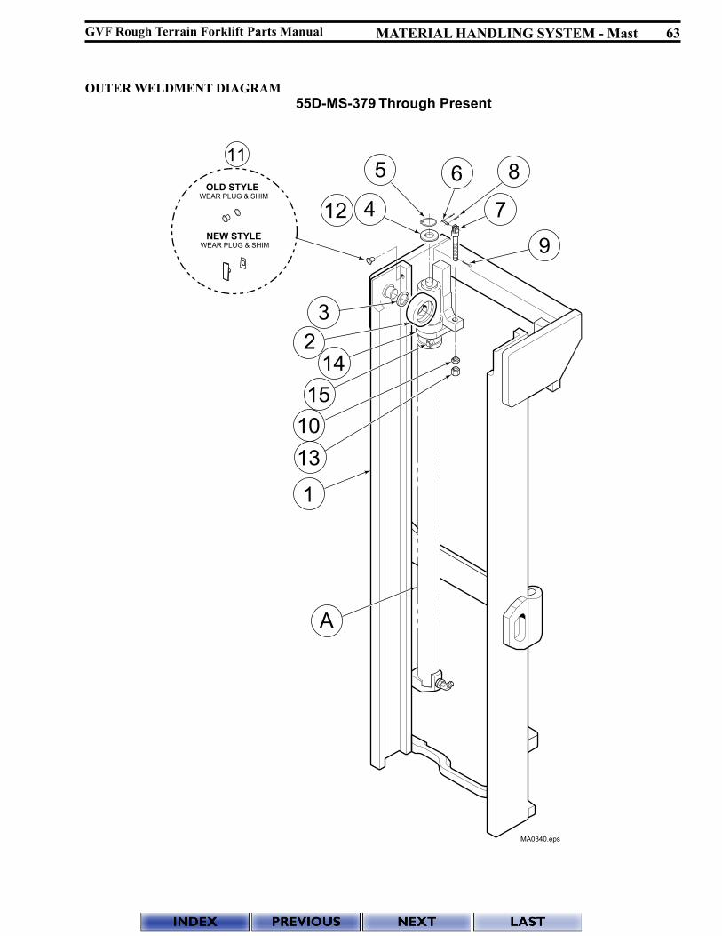
MATERIAL HANDLING SYSTEM - Mast 63GVF Rough Terrain Forklift Parts Manual
10 686462 R6
3
4
13
1
65
12
1510
8
7
9
MA0340.eps
214
A
11OLD STYLE
WEAR PLUG & SHIM
NEW STYLEWEAR PLUG & SHIM
Outer Weldment55D-MS-379 Through Present
OUTER WELDMENT DIAGRAM

MATERIAL HANDLING SYSTEM - Mast64 GVF Rough Terrain Forklift Parts Manual
ITEM QTY PART# Description ITEM QTY PART# Description
A 1 268089LB, 4 Carriage Assembly 12 3 2 SS Cylinder Top Wear PadB 1 268092 Carriage Frame 13 1 2 SS Cylinder Face Wear PadC 2 283509 Sideshift Rod 14 2 1 SS Cylinder Rod WiperD 2 255807 Installation Kit1 2 1 O-ring 16 2 234034 Chain Anchor2 2 1 Rod Seal 17 2 3 Chain Anchor Pin3 6 N 2970 Capscrew (or 767614) 18 4 6508 Cotter Pin4 4 680218 Capscrew 19 2 6518 Cotter Pin5 2 283508 Cylinder Head 20 2 200007 Jam Nut6 3 7403 Grease Fitting 21 2 200006 Full Nut7 3 624280 Grease Fitting 22 16 631881 Load Roller Shim8 2 283510 Lower Carriage Claw 23 4 231359 Load Roller
24 2 231426 Load Roller10 3 2 Spine Bar Wear Pad 25 2 658378 Retainer
26 2 254563 Spacer
48 Inch Integral Carriage for E50-MS MastCommon Parts Group: 251988, ITA Class: II, # of Rollers: 6, Carriage Width: 1219.2 mm or 48”, Carriage Part #: 268089LB
Notes:1 - Included in Seal Kit P/N 2938802 - Included in Wear Pad Service Kit P/N 2839753 - Items vary per application - See chart CPG 4-24 - Does not include items 4, 16, 17, 18, 19, 20, 21, 22, 23, 24 and 25.
Note:A - Does not include items: 4, 16, 17, 18, 19, 20, 21, 22, 23, 24 and 25.
COMMON PARTS, 48” INTEGRAL CARRIAGE

MATERIAL HANDLING SYSTEM - Mast 65GVF Rough Terrain Forklift Parts Manual
11686462 R6
OUTER UPRIGHT
OUTER UPRIGHT
OUTER UPRIGHT
REF 1 REF 1 REF 1QTY 1 QTY 1 QTY 1
56 202473 81 202498 107 20252357 202474 82 202499 109 20252458 202475 83 202500 110 20252559 202476 84 202501 111 20252660 202477 85 202502 112 20252761 202478 86 202503 113 20252862 202479 87 202504 114 20252963 202480 88 202505 116 20253064 202481 89 202506 117 20253165 202482 90 202507 118 20253266 202483 91 202508 119 20253367 202484 92 202509 120 20253468 202485 93 202510 121 20253569 202486 94 202511 123 20253670 202487 95 202512 124 20253771 202488 96 202513 125 20253872 202489 97 202514 126 20253973 202490 98 202515 127 20254074 202491 99 202516 128 20254175 202492 100 202517 130 20254276 202493 101 202518 131 20254377 202494 103 202519 132 20254478 202495 104 202520 133 20254579 202496 105 202521 134 20254680 202497 106 202522 135 202547
OCL (IN)
OCL - Outer Channel Length
WLD-1
OCL (IN)
OCL (IN)
REF QTY PART # DESCRIPTION REF QTY PART # DESCRIPTIONA 1 n Mainlift Cylinders 8 2 201434 Chain Anchor1 1 n Outer Upright - See WLD-4 9 2 6518 Cotter Pin2 4 662145 Load Roller 10 2 200007 Jam Nut3 * 631881 Load Roller Shim 11 1 212587 Wear Plug Kit4 * 200524 Cylinder Shim 12 2 200006 Nut5 2 3129 Snap Ring 13 * 200525 Cylinder Shim6 2 678667 Chain Pin 14 2 200784 Bumper7 4 6508 Cotter Pin 15 2 201895 Clamp
WLD-2
* - Quantity will vary. n - See specific charts for part numbers.
Common Parts55D-MS-379 Through Present
Standard 12’ Mast
COMMON PARTS

MATERIAL HANDLING SYSTEM - Mast66 GVF Rough Terrain Forklift Parts Manual
12 686462 R6
MA0396.eps
2
5
7
1
43
6
Inner Weldment55D-MS-001 Through Present
INNER WELDMENT DIAGRAM

MATERIAL HANDLING SYSTEM - Mast 67GVF Rough Terrain Forklift Parts Manual
13686462 R6
Common Parts55D-MS-001 Through Present
INNER UPRIGHT
INNER UPRIGHT
INNER UPRIGHT
REF 1 REF 1 REF 1QTY 1 QTY 1 QTY 1
56 684143 81 683696 107 68811157 683672 82 683697 109 68811258 683673 83 683698 110 68811359 683674 84 683699 111 68811460 683675 85 683700 112 68811561 683676 86 683701 113 68811662 683677 87 683702 114 68811763 683678 88 683703 116 68811864 683679 89 683704 117 68811965 683680 90 683705 118 68812066 683681 91 683706 119 68812167 683682 92 683707 120 68812268 683683 93 683708 121 68812369 683684 94 683709 123 68812470 683685 95 683710 124 68812571 683686 96 683711 125 68812672 683687 97 683712 126 68812773 683688 98 683713 127 68812874 683689 99 683714 128 68812975 683690 100 683715 130 68813076 683691 101 683716 131 68813177 683692 103 688107 132 68813278 683693 104 688108 133 68813379 683694 105 688109 134 68813480 683695 106 688110 135 688135
WLD-5
OCL (IN)
OCL - Outer Channel Length
OCL (IN)
OCL (IN)
REF QTY PART # DESCRIPTION REF QTY PART # DESCRIPTION1 1 n Inner Upright - See WLD-5 5 2 660051 Chain Sheave2 2 683820 M10x1,5x16 Capscrew 6 * 631881 Load Roller Shim3 2 683826 M10 Lockwasher 7 2 662145 Load Roller4 2 683802 Pin Assembly
WLD-6
* - Quantity will vary. n - See specific charts for part numbers.
Standard 12’ Mast
COMMON PARTS
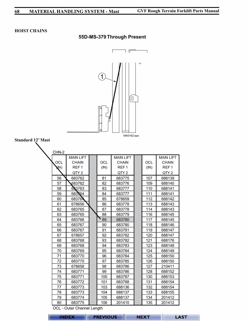
MATERIAL HANDLING SYSTEM - Mast68 GVF Rough Terrain Forklift Parts Manual
15686462 R6
1
MA0162.eps
Hoist Chains55D-MS-379 Through Present
MAIN LIFT CHAIN
MAIN LIFT CHAIN
MAIN LIFT CHAIN
REF 1 REF 1 REF 1QTY 2 QTY 2 QTY 2
56 683762 81 683775 107 68813957 683762 82 683776 109 68814058 683763 83 683777 110 68814159 683764 84 683777 111 68814160 683764 85 678659 112 68814261 678656 86 683778 113 68814362 683765 87 683778 114 68814363 683765 88 683779 116 68814564 683766 89 683780 117 68814565 683767 90 683780 118 68814666 683767 91 683781 119 68814767 678657 92 683782 120 68814768 683768 93 683782 121 68817669 683768 94 683783 123 68814870 683769 95 683784 124 68814971 683770 96 683784 125 68815072 683770 97 683785 126 68815073 678658 98 683786 127 21041174 683771 99 683786 128 68815275 683771 100 683787 130 68815376 683772 101 683788 131 68815477 683773 103 688136 132 68815478 683773 104 688137 133 68815579 683774 105 688137 134 20141280 683775 106 201410 135 201412
CHN-2
OCL (IN)
OCL - Outer Channel Length
OCL (IN)
OCL (IN)
Standard 12’ Mast
HOIST CHAINS

MATERIAL HANDLING SYSTEM - Mast 69GVF Rough Terrain Forklift Parts Manual
16 686462 R6
Hydraulic Group
MA0398.eps
54321
6
8
7
These items vary from truck totruck. See the Mast InstallationAccessories on pages for the correct part number.
REF QTY PART # DESCRIPTION REF QTY PART # DESCRIPTION1 2 683823 M10x50-8.8 Capscrew 5 1 683831 Bar2 2 684649 M10x25-8.8 Capscrew 6 2 601377 Fitting3 4 683826 M10 Lockwasher 7 1 605348 Fitting4 1 n Lowering Control Valve 8 1 605761 Fitting
HYD-1
* - Quantity will vary. n - See specific charts for part numbers.
HYDRAULIC GROUP
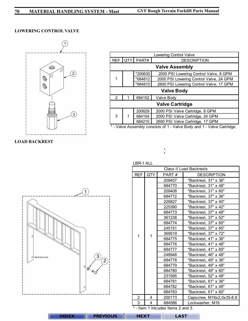
MATERIAL HANDLING SYSTEM - Mast70 GVF Rough Terrain Forklift Parts Manual
17686462 R6
1
3
2
1
32
Backrest-2.eps
Lowering Control Valve
Load Backrest
REF QTY PART # DESCRIPTION209407 *Backrest, 31" x 36"684770 *Backrest, 31" x 48"209408 *Backrest, 31" x 60"684772 *Backrest, 37" x 36"226827 *Backrest, 37" x 40"225390 *Backrest, 37" x 42"684773 *Backrest, 37" x 48"361238 *Backrest, 37" x 52"684774 *Backrest, 37" x 60"245151 *Backrest, 37" x 65"369519 *Backrest, 37" x 72"684775 *Backrest, 41" x 36"684776 *Backrest, 41" x 48"684777 *Backrest, 41" x 60"248948 *Backrest, 46" x 48"684778 *Backrest, 49" x 36"684779 *Backrest, 49" x 48"684780 *Backrest, 49" x 60"231595 *Backrest, 52" x 48"684781 *Backrest, 61" x 36"684782 *Backrest, 61" x 48"684783 *Backrest, 61" x 60"
2 4 200173 Capscrew, M16x2,0x35-8.83 4 684586 Lockwasher, M16
LBR-1 ALL
* - Item 1 inlcudes items 2 and 3.
Class II Load Backrests
1 1
REF QTY PART# DESCRIPTION
*200630 2000 PSI Lowering Control Valve, 8 GPM*684812 2000 PSI Lowering Control Valve, 24 GPM*684810 2600 PSI Lowering Control Valve, 17 GPM
2 1 684152 Valve Body
200629 2000 PSI Valve Cartridge, 8 GPM684154 2000 PSI Valve Cartridge, 24 GPM684210 2600 PSI Valve Cartridge, 17 GPM
Lowering Control Valve
1
3 1
* - Valve Assembly consists of 1 - Valve Body and 1 - Valve Cartridge.
Valve Assembly
Valve Body
Valve Cartridge
LOWERING CONTROL VALVE
LOAD BACKREST
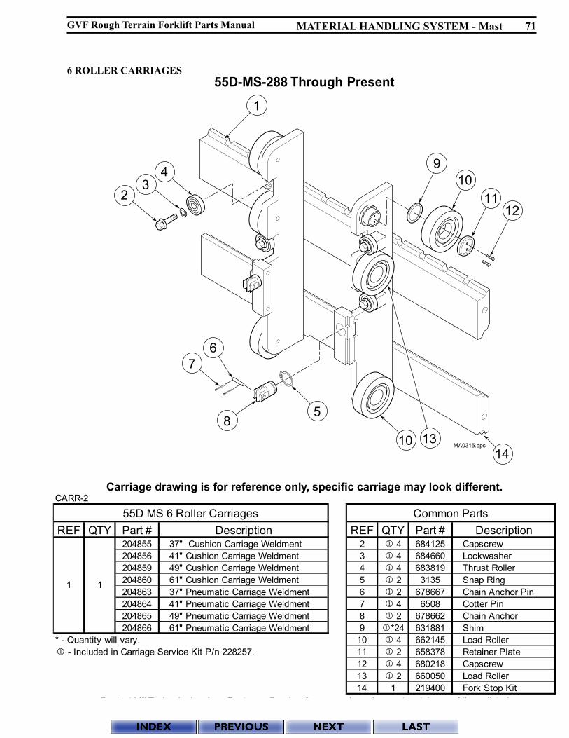
MATERIAL HANDLING SYSTEM - Mast 71GVF Rough Terrain Forklift Parts Manual
17686462 R6
1
3
2
1
32
Backrest-2.eps
Lowering Control Valve
Load Backrest
REF QTY PART # DESCRIPTION209407 *Backrest, 31" x 36"684770 *Backrest, 31" x 48"209408 *Backrest, 31" x 60"684772 *Backrest, 37" x 36"226827 *Backrest, 37" x 40"225390 *Backrest, 37" x 42"684773 *Backrest, 37" x 48"361238 *Backrest, 37" x 52"684774 *Backrest, 37" x 60"245151 *Backrest, 37" x 65"369519 *Backrest, 37" x 72"684775 *Backrest, 41" x 36"684776 *Backrest, 41" x 48"684777 *Backrest, 41" x 60"248948 *Backrest, 46" x 48"684778 *Backrest, 49" x 36"684779 *Backrest, 49" x 48"684780 *Backrest, 49" x 60"231595 *Backrest, 52" x 48"684781 *Backrest, 61" x 36"684782 *Backrest, 61" x 48"684783 *Backrest, 61" x 60"
2 4 200173 Capscrew, M16x2,0x35-8.83 4 684586 Lockwasher, M16
LBR-1 ALL
* - Item 1 inlcudes items 2 and 3.
Class II Load Backrests
1 1
REF QTY PART# DESCRIPTION
*200630 2000 PSI Lowering Control Valve, 8 GPM*684812 2000 PSI Lowering Control Valve, 24 GPM*684810 2600 PSI Lowering Control Valve, 17 GPM
2 1 684152 Valve Body
200629 2000 PSI Valve Cartridge, 8 GPM684154 2000 PSI Valve Cartridge, 24 GPM684210 2600 PSI Valve Cartridge, 17 GPM
Lowering Control Valve
1
3 1
* - Valve Assembly consists of 1 - Valve Body and 1 - Valve Cartridge.
Valve Assembly
Valve Body
Valve Cartridge
22 686462 R6
MA0315.eps108
910
13
32
4
5
14
1
67
1112
6 Roller Carriages
REF QTY Part # Description REF QTY Part # Description204855 37" Cushion Carriage Weldment 2 1 4 684125 Capscrew 204856 41" Cushion Carriage Weldment 3 1 4 684660 Lockwasher204859 49" Cushion Carriage Weldment 4 1 4 683819 Thrust Roller 204860 61" Cushion Carriage Weldment 5 1 2 3135 Snap Ring204863 37" Pneumatic Carriage Weldment 6 1 2 678667 Chain Anchor Pin204864 41" Pneumatic Carriage Weldment 7 1 4 6508 Cotter Pin204865 49" Pneumatic Carriage Weldment 8 1 2 678662 Chain Anchor204866 61" Pneumatic Carriage Weldment 9 1*24 631881 Shim
10 1 4 662145 Load Roller11 1 2 658378 Retainer Plate12 1 4 680218 Capscrew 13 1 2 660050 Load Roller14 1 219400 Fork Stop Kit
Common Parts
* - Quantity will vary.1 - Included in Carriage Service Kit P/n 228257.
CARR-2
11
55D MS 6 Roller Carriages
Contact Lift Technologies, Inc. Customer Service if your carriage does not match any of those listed(Mast PID number needed).
Carriage drawing is for reference only, specific carriage may look different.
55D-MS-288 Through Present6 ROLLER CARRIAGES
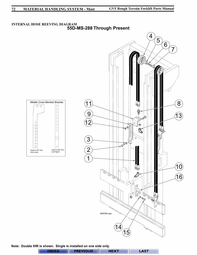
MATERIAL HANDLING SYSTEM - Mast72 GVF Rough Terrain Forklift Parts Manual
26 686462 R6
Internal Hose Reeving
MA0394.eps
11 8
10
13
16
912
3
12
1415
45
67
Note: Double IHR is shown. Single is installed on one side only.
Used on 65" OCLAnd Lower.
Used on 66" OCLand Higher.
Middle Cross Member Bracket
55D-MS-288 Through PresentINTERNAL HOSE REEVING DIAGRAM
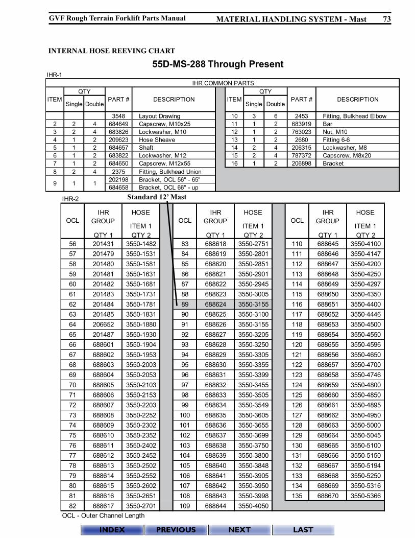
MATERIAL HANDLING SYSTEM - Mast 73GVF Rough Terrain Forklift Parts Manual
27686462 R6
Internal Hose Reeving
IHR-2
HOSE HOSE HOSE
ITEM 1 ITEM 1 ITEM 1QTY 1 QTY 2 QTY 1 QTY 2 QTY 1 QTY 2
56 201431 3550-1482 83 688618 3550-2751 110 688645 3550-410057 201479 3550-1531 84 688619 3550-2801 111 688646 3550-414758 201480 3550-1581 85 688620 3550-2851 112 688647 3550-420059 201481 3550-1631 86 688621 3550-2901 113 688648 3550-425060 201482 3550-1681 87 688622 3550-2945 114 688649 3550-429761 201483 3550-1731 88 688623 3550-3005 115 688650 3550-435062 201484 3550-1781 89 688624 3550-3055 116 688651 3550-440063 201485 3550-1831 90 688625 3550-3100 117 688652 3550-444664 206652 3550-1880 91 688626 3550-3155 118 688653 3550-450065 201487 3550-1930 92 688627 3550-3205 119 688654 3550-455066 688601 3550-1904 93 688628 3550-3250 120 688655 3550-459667 688602 3550-1953 94 688629 3550-3305 121 688656 3550-465068 688603 3550-2003 95 688630 3550-3355 122 688657 3550-470069 688604 3550-2053 96 688631 3550-3399 123 688658 3550-474670 688605 3550-2103 97 688632 3550-3455 124 688659 3550-480071 688606 3550-2153 98 688633 3550-3505 125 688660 3550-485072 688607 3550-2203 99 688634 3550-3549 126 688661 3550-489573 688608 3550-2252 100 688635 3550-3605 127 688662 3550-495074 688609 3550-2302 101 688636 3550-3655 128 688663 3550-500075 688610 3550-2352 102 688637 3550-3699 129 688664 3550-504576 688611 3550-2402 103 688638 3550-3750 130 688665 3550-510077 688612 3550-2452 104 688639 3550-3800 131 688666 3550-515078 688613 3550-2502 105 688640 3550-3848 132 688667 3550-519479 688614 3550-2552 106 688641 3550-3905 133 688668 3550-525080 688615 3550-2602 107 688642 3550-3950 134 688669 3550-531681 688616 3550-2651 108 688643 3550-3998 135 688670 3550-536682 688617 3550-2701 109 688644 3550-4050
OCL
OCL - Outer Channel Length
OCL OCLIHR
GROUPIHR
GROUPIHR
GROUP
55D-MS-288 Through Present
Single Double Single Double
3548 Layout Drawing 10 3 6 2453 Fitting, Bulkhead Elbow2 2 4 684649 Capscrew, M10x25 11 1 2 683919 Bar3 2 4 683826 Lockwasher, M10 12 1 2 763023 Nut, M104 1 2 209623 Hose Sheave 13 1 2 2680 Fitting 6-65 1 2 684657 Shaft 14 2 4 206315 Lockwasher, M86 1 2 683822 Lockwasher, M12 15 2 4 787372 Capscrew, M8x207 1 2 684650 Capscrew, M12x55 16 1 2 206898 Bracket8 2 4 2375 Fitting, Bulkhead Union
202198 Bracket, OCL 56" - 65"684658 Bracket, OCL 66" - up
IHR-1
19
IHR COMMON PARTS
1
QTYITEM PART # DESCRIPTION ITEM
QTYPART # DESCRIPTION
1
Standard 12’ Mast
INTERNAL HOSE REEVING CHART
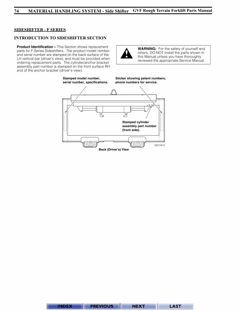
MATERIAL HANDLING SYSTEM - Side Shifter74 GVF Rough Terrain Forklift Parts Manual
SIDESHIFTER - F SERIES
INTRODUCTION TO SIDESHIFTER SECTION
219941 Rev. 2 9
I NSPECTION & MAINTENANCE
DailyCheck items shown each day. Report problems to yoursupervisor. See Service Manual for troubleshooting,maintenance and repair procedures.
100-HourEvery time the lift truck is serviced or every 100 hours oftruck operation, whichever comes first, complete thefollowing maintenance procedures:
• Check for loose or missing bolts, worn ordamaged hoses, hydraulic leaks, anddamaged or missing fork stops.
• Inspect lower hooks for wear and proper clearance.Adjust if necessary (see Step 4, Installation). Tightenlower hook capscrews to 120 ft.-lbs (165 Nm).
300-HourAfter each 300 hours of truck operation, in addition to the100-hour maintenance, perform the following procedures:
• Tighten backrest capscrews (Cascade) to145 ft.-lbs. (195 Nm).
• Apply general-purpose lithium-based chassis grease toSideshifter upper and lower bearings.
1000-HourAfter each 1000 hours of truck operation, in addition to the100 and 300-hour maintenance, perform the followingprocedures:
• Inspect upper and lower bearings for wear. If anybearing is worn to less than 3/32 in. (2.5 mm) thickness,replace the entire bearing set. See Service Manual forreplacement procedure.
• Inspect forks for wear. NOTE: Fork Safety Kit 3014162 isavailable containing wear calipers, inspection sheets andsafety poster. Also available is fork hook & carriage weargauge 209560 (CL II), and 209561 (CL III).
WARNING: After completing any serviceprocedure, always test the sideshifterthrough five complete cycles. First testwith no load, then test with a load to makesure the attachment operates correctlybefore returning it to the job.
Product Identification – This Section shows replacementparts for F-Series Sideshifters. The product model numberand serial number are stamped on the back surface of theLH vertical bar (driver's view), and must be provided whenordering replacement parts. The cylinder/anchor bracketassembly part number is stamped on the front surface RHend of the anchor bracket (driver's view).
ARTS
Back (Driver's) View
WARNING: For the safety of yourself andothers, DO NOT install the parts shown inthis Manual unless you have thoroughlyreviewed the appropriate Service Manual.
SS0186.ill
Forks
Cylinderand hosesfor leaks
Upper andlower hookengagement
Fasteners
SS0158.ill
ForkStops
Stamped model number,serial number, specifications.
Sticker showing patent numbers,phone numbers for service.
P
Stamped cylinderassembly part number(front side).
Backrest
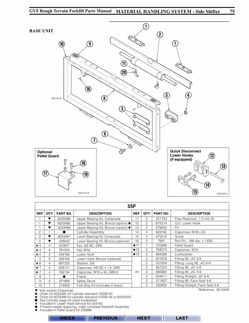
MATERIAL HANDLING SYSTEM - Side Shifter 75GVF Rough Terrain Forklift Parts Manual
10 219941 Rev. 2
P ARTS
5
1
1
2
0 9
3
^
76
!
)
SS0144.ill48
$
SS0169.ill%
@
#
Quick DisconnectLower Hooks(if equipped)
&
SS0174.ill
*
(
REF QTY PART NO. DESCRIPTION
11 2 221733 Flow Restrictor, 1.5 mm ID12 2 675514 Q.D. Lower Hook13 2 678832 Pin14 4 683182 Capscrew, M16 x 3515 2 675515 Guide16 2 7891 Roll Pin, .188 dia. x 1.625
◆17 1 220689 Pallet Guard◆18 2 769573 Capscrew, M16◆19 2 684586 Lockwasher
2 601676 Fitting-90, JIC 6-62 207304 Fitting- Long 90, JIC 6-62 667222 Fitting-90, JIC 5-6
20 2 666984 Fitting-90, JIC 4-62 604511 Fitting-Straight, JIC 6-62 211807 Fitting-90, Face Seal 4-62 220832 Fitting-Straight, Face Seal 4-6
Reference: SK-6349
REF QTY PART NO. DESCRIPTION
1 ▼ 6020486 Upper Bearing Kit, Composite1 ▼ 6033485 Upper Bearing Kit, Bronze (option) ✖1 ▼ 6033486 Upper Bearing Kit, Bronze (option) ✚2 1 ■ Cylinder Assembly3 ▼ 6033487 Lower Bearing Kit, Composite3 ▼ 226842 Lower Bearing Kit, Bronze (optional)
★ 4 4 553857 Nut, 5/8 NC, GR5 ★ 4 4 781534 Nut, M16 ★ 5 2 204186 Lower Hook
5 2 228166 Lower Hook, Bronze (optional) ★ 6 4 667225 Washer, 5/8 ★ 7 4 639121 Capscrew, 5/8 NC x 1.5, GR5 ★ 7 4 766154 Capscrew, M16 x 45, GR8.8
8 1 ● Frame9 2 221906 Safety Decal10 1 219400 Fork Stop Kit (Includes 2 stops)
▼ Kits contain 2 bearings.✖ Order Kit 6033485 for cylinder stamped 10039-XX.✚ Order Kit 6033486 for cylinder stamped 21006-XX or 6XXXXXX.■ See Cylinder page for parts breakdown.★ Included in Lower Hook Service Kit 204182● If Frame needs replacing, order complete Sideshift Assembly◆ Included in Pallet Guard Kit 220688.
55F
OptionalPallet Guard
Base UnitBASE UNIT
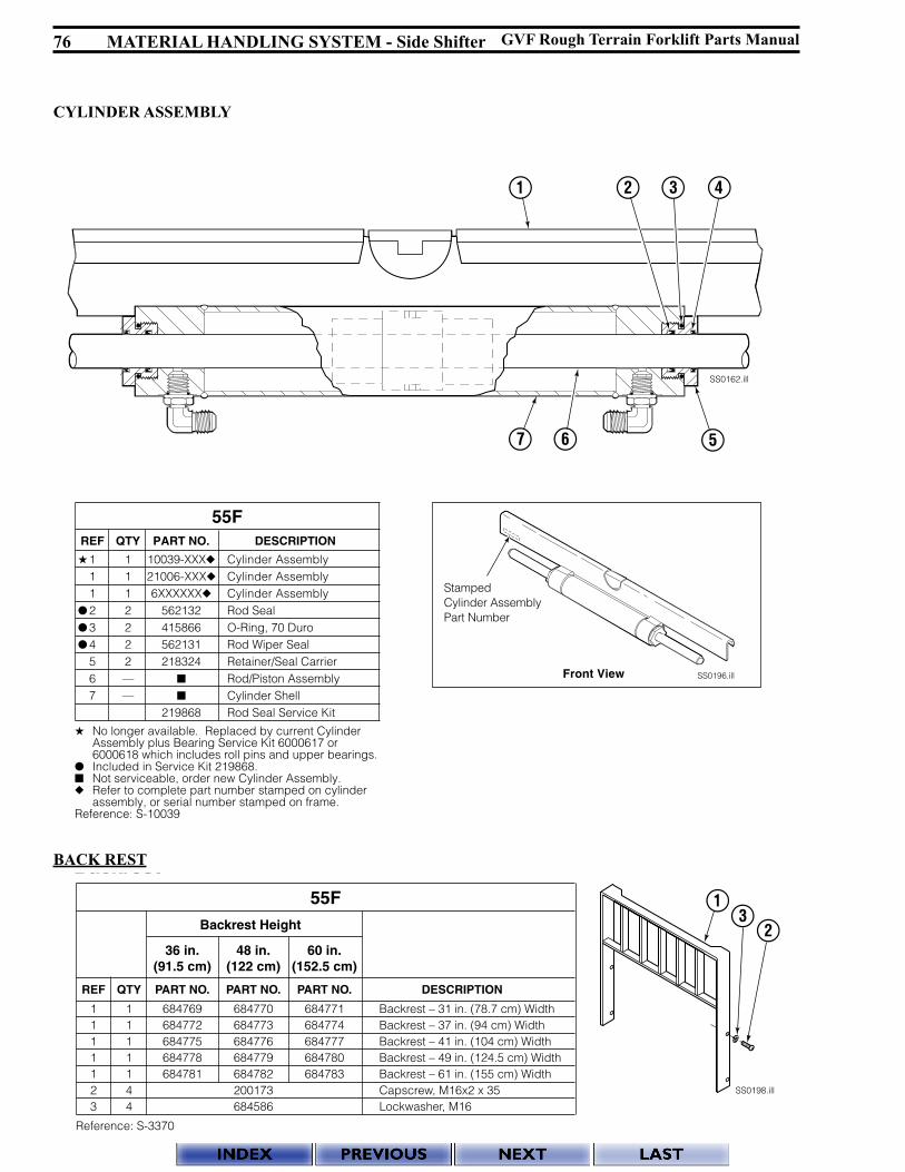
MATERIAL HANDLING SYSTEM - Side Shifter76 GVF Rough Terrain Forklift Parts Manual
219941 Rev. 2 11
P ARTSCylinder Assembly
SS0162.ill
1 2 3 4
7 6 5
Backrest
55FREF QTY PART NO. DESCRIPTION
★1 1 10039-XXX◆ Cylinder Assembly1 1 21006-XXX◆ Cylinder Assembly1 1 6XXXXXX◆ Cylinder Assembly
● 2 2 562132 Rod Seal ● 3 2 415866 O-Ring, 70 Duro ● 4 2 562131 Rod Wiper Seal
5 2 218324 Retainer/Seal Carrier6 — ■ Rod/Piston Assembly7 — ■ Cylinder Shell
219868 Rod Seal Service Kit
★ No longer available. Replaced by current CylinderAssembly plus Bearing Service Kit 6000617 or6000618 which includes roll pins and upper bearings.
● Included in Service Kit 219868.■ Not serviceable, order new Cylinder Assembly.◆ Refer to complete part number stamped on cylinder
assembly, or serial number stamped on frame.Reference: S-10039
SS0196.ill
StampedCylinder AssemblyPart Number
Front View
55FBackrest Height
36 in. 48 in. 60 in.(91.5 cm) (122 cm) (152.5 cm)
REF QTY PART NO. PART NO. PART NO. DESCRIPTION
1 1 684769 684770 684771 Backrest – 31 in. (78.7 cm) Width1 1 684772 684773 684774 Backrest – 37 in. (94 cm) Width1 1 684775 684776 684777 Backrest – 41 in. (104 cm) Width1 1 684778 684779 684780 Backrest – 49 in. (124.5 cm) Width1 1 684781 684782 684783 Backrest – 61 in. (155 cm) Width2 4 200173 Capscrew, M16x2 x 353 4 684586 Lockwasher, M16
Reference: S-3370
13
SS0198.ill
2
CYLINDER ASSEMBLY
BACK REST
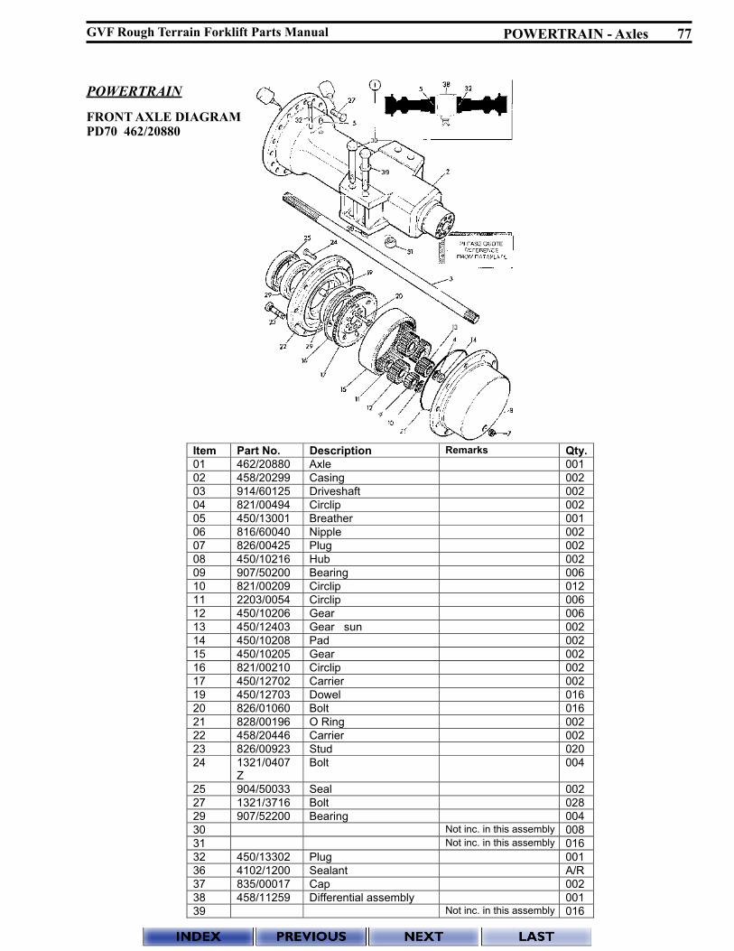
POWERTRAIN - Axles 77GVF Rough Terrain Forklift Parts Manual
POWERTRAIN
FRONT AXLE DIAGRAM PD70 462/20880
AXLE PD70, 462/20880 Item Part No. Description Remarks Qty.01 462/20880 Axle 001 02 458/20299 Casing 002 03 914/60125 Driveshaft 002 04 821/00494 Circlip 002 05 450/13001 Breather 001 06 816/60040 Nipple 002 07 826/00425 Plug 002 08 450/10216 Hub 002 09 907/50200 Bearing 006 10 821/00209 Circlip 012 11 2203/0054 Circlip 006 12 450/10206 Gear 006 13 450/12403 Gear sun 002 14 450/10208 Pad 002 15 450/10205 Gear 002 16 821/00210 Circlip 002 17 450/12702 Carrier 002 19 450/12703 Dowel 016 20 826/01060 Bolt 016 21 828/00196 O Ring 002 22 458/20446 Carrier 002 23 826/00923 Stud 020 24 1321/0407
ZBolt 004
25 904/50033 Seal 002 27 1321/3716 Bolt 028 29 907/52200 Bearing 004 30 Not inc. in this assembly 008 31 Not inc. in this assembly 016 32 450/13302 Plug 001 36 4102/1200 Sealant A/R 37 835/00017 Cap 002 38 458/11259 Differential assembly 001 39 Not inc. in this assembly 016
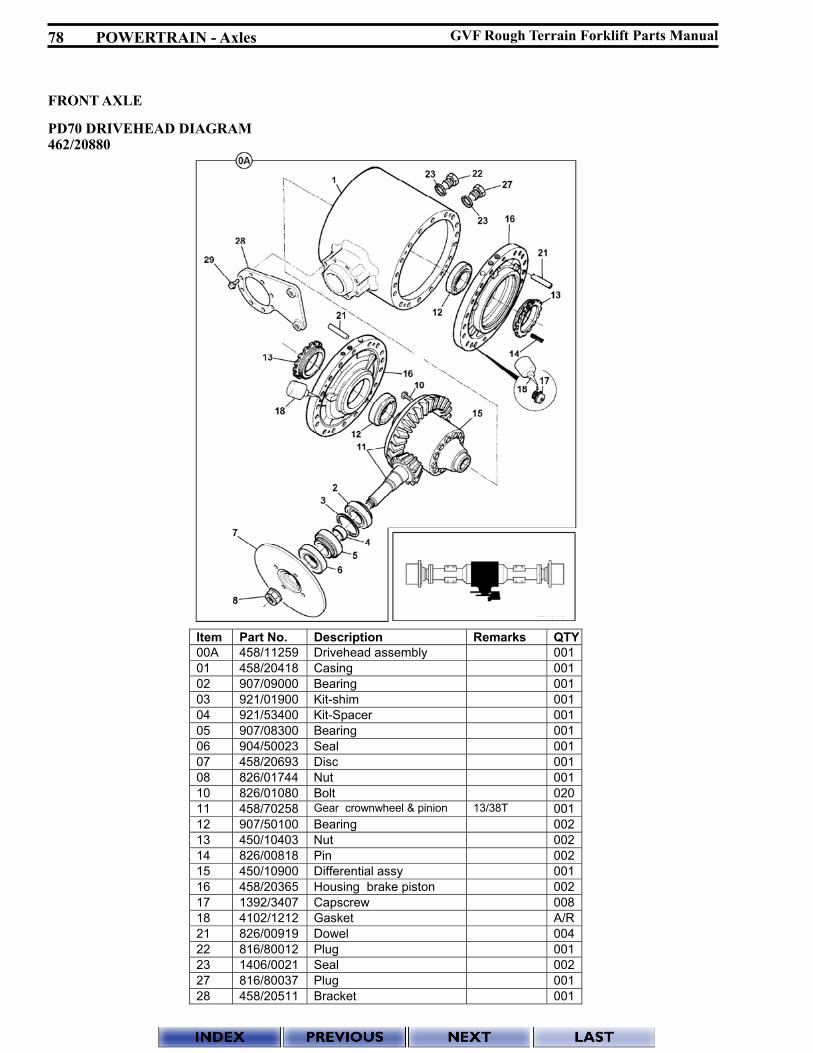
POWERTRAIN - Axles78 GVF Rough Terrain Forklift Parts Manual
FRONT AXLE
PD70 DRIVEHEAD DIAGRAM 462/20880
AXLE PD70, DRIVEHEAD, 462/20880
Item Part No. Description Remarks QTY00A 458/11259 Drivehead assembly 00101 458/20418 Casing 00102 907/09000 Bearing 00103 921/01900 Kit-shim 00104 921/53400 Kit-Spacer 00105 907/08300 Bearing 00106 904/50023 Seal 00107 458/20693 Disc 00108 826/01744 Nut 00110 826/01080 Bolt 02011 458/70258 Gear crownwheel & pinion 13/38T 00112 907/50100 Bearing 00213 450/10403 Nut 00214 826/00818 Pin 00215 450/10900 Differential assy 00116 458/20365 Housing brake piston 00217 1392/3407 Capscrew 00818 4102/1212 Gasket A/R 21 826/00919 Dowel 00422 816/80012 Plug 00123 1406/0021 Seal 00227 816/80037 Plug 00128 458/20511 Bracket 001

POWERTRAIN - Axles 79GVF Rough Terrain Forklift Parts Manual
BRAKES 462/20880 DIAGRAMFRONT AXLE PD70 AXLE PD70, BRAKES, 462/20880
Item Part No. Description QTY01 458/20371 Piston 002 02 813/50012 Seal 002 03 813/50026 Seal 002 04 450/10213 Pin 006 05 458/20285 Plate 012 06 458/20353 Plate 010 07 450/10215 Carrier 002 08 2203/0071 Circlip 004 11 816/60040 Nipple 002 12 835/00017 Cap 002 13 450/18204 Pin 006 14 814/00365 Spring 006 15 448/16905 Bush 006 17 2203/1020 Circlip 006
AXLE PD70, BRAKES, 462/20880
Item Part No. Description QTY01 458/20371 Piston 002 02 813/50012 Seal 002 03 813/50026 Seal 002 04 450/10213 Pin 006 05 458/20285 Plate 012 06 458/20353 Plate 010 07 450/10215 Carrier 002 08 2203/0071 Circlip 004 11 816/60040 Nipple 002 12 835/00017 Cap 002 13 450/18204 Pin 006 14 814/00365 Spring 006 15 448/16905 Bush 006 17 2203/1020 Circlip 006
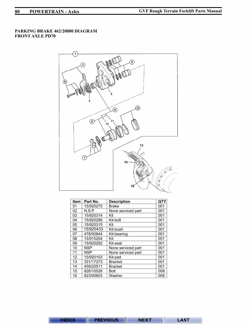
POWERTRAIN - Axles80 GVF Rough Terrain Forklift Parts Manual
PARKING BRAKE 462/20880 DIAGRAMFRONT AXLE PD70 AXLE PD70, PARKING BRAKE, 462/20880
Item Part No. Description QTY01 15/920270 Brake 001 02 N.S.P None serviced part 001 03 15/920314 Kit 001 04 15/920289 Kit-bolt 001 05 15/920315 Kit 001 06 15/920293 Kit-bush 001 07 478/00844 Kit-bearing 001 08 15/915204 Kit 001 09 15/920292 Kit-seal 001 10 NSP None serviced part 001 11 NSP None serviced part 001 12 15/920103 Kit-pad 001 13 331/17273 Bracket 001 14 458/20511 Bracket 001 15 826/10526 Bolt 008 16 823/00603 Washer 008
AXLE PD70, PARKING BRAKE, 462/20880
Item Part No. Description QTY01 15/920270 Brake 001 02 N.S.P None serviced part 001 03 15/920314 Kit 001 04 15/920289 Kit-bolt 001 05 15/920315 Kit 001 06 15/920293 Kit-bush 001 07 478/00844 Kit-bearing 001 08 15/915204 Kit 001 09 15/920292 Kit-seal 001 10 NSP None serviced part 001 11 NSP None serviced part 001 12 15/920103 Kit-pad 001 13 331/17273 Bracket 001 14 458/20511 Bracket 001 15 826/10526 Bolt 008 16 823/00603 Washer 008
15/920433
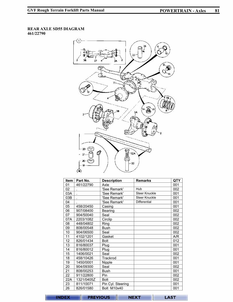
POWERTRAIN - Axles 81GVF Rough Terrain Forklift Parts Manual
REAR AXLE SD55 DIAGRAM461/22790
AXLE SD55, 461/22790 Item Part No. Description Remarks QTY01 461/22790 Axle 001 02 . 'See Remark' Hub 002 03A . 'See Remark' Steer Knuckle 001 03B . 'See Remark' Steer Knuckle 001 04 . 'See Remark' Differential 001 05 458/20450 Casing 001 06 907/08400 Bearing 002 07 904/50040 Seal 002 07A 2203/1082 Circlip 002 08 448/04802 Ring 002 09 808/00548 Bush 002 10 904/06500 Seal 002 11 4102/1201 Gasket A/R 12 826/01434 Bolt 012 13 816/80037 Plug 001 14 816/80012 Plug 001 15 1406/0021 Seal 002 18 458/10426 Trackrod 001 19 1450/0001 Nipple 001 20 904/09300 Seal 002 21 808/00253 Bush 001 22 911/22800 Pin 002 22A 1321/0405Z Bolt 002 23 Pin Not inc. with this assy 001 26 Bolt Not inc. with this assy 001 27 'See Remark' Not inc. with this assy 001
Item Part No. Description Remarks QTY01 461/22790 Axle 001 02 . 'See Remark' Hub 002 03A . 'See Remark' Steer Knuckle 001 03B . 'See Remark' Steer Knuckle 001 04 . 'See Remark' Differential 001 05 458/20450 Casing 001 06 907/08400 Bearing 002 07 904/50040 Seal 002 07A 2203/1082 Circlip 002 08 448/04802 Ring 002 09 808/00548 Bush 002 10 904/06500 Seal 002 11 4102/1201 Gasket A/R 12 826/01434 Bolt 012 13 816/80037 Plug 001 14 816/80012 Plug 001 15 1406/0021 Seal 002 18 458/10426 Trackrod 001 19 1450/0001 Nipple 001 20 904/09300 Seal 002 21 808/00253 Bush 001 22 911/22800 Pin 002 22A 1321/0405Z Bolt 002 23 811/10071 Pin Cyl. Steering 001 26 826/01580 Bolt M10x40 001

POWERTRAIN - Axles82 GVF Rough Terrain Forklift Parts Manual
DRIVEHEAD 461/22790 DIAGRAMREAR AXLE SD55
AXLE SD55, DRIVEHEAD, 461/22790
Item Part No. Description Remarks QTY 01 448/56590 Differential assembly 001 02 448/15701 Casting 001 03 448/23500 Differential case 001 04 448/36400 Differential gear kit 001 05 448/36400 Differential gesr kit 001 06 448/05408 Pin 001 07 808/00210 Washer 002 08 808/00209 Washer 002 09 907/09200 Bearing 002 10 448/05405 Nut 002 11 458/70025 Gear, crownwheel &
pinion 33T/ 11T 001
12 826/01084 Bolt 012 15 . 'See Remark' 001 16 907/09000 Bearing 001 17 921/01900 Kit-shim A/R 18 921/53300 Spacer 001 19 907/09100 Bearing 001 20 904/50023 Seal 001 21 450/27200 Yoke 001 22 Washer Not required 001 23 826/01483 Nut 001 24 826/00818 Pin 002 25 826/01585 Bolt 001 26 2102/0816 Pin 008
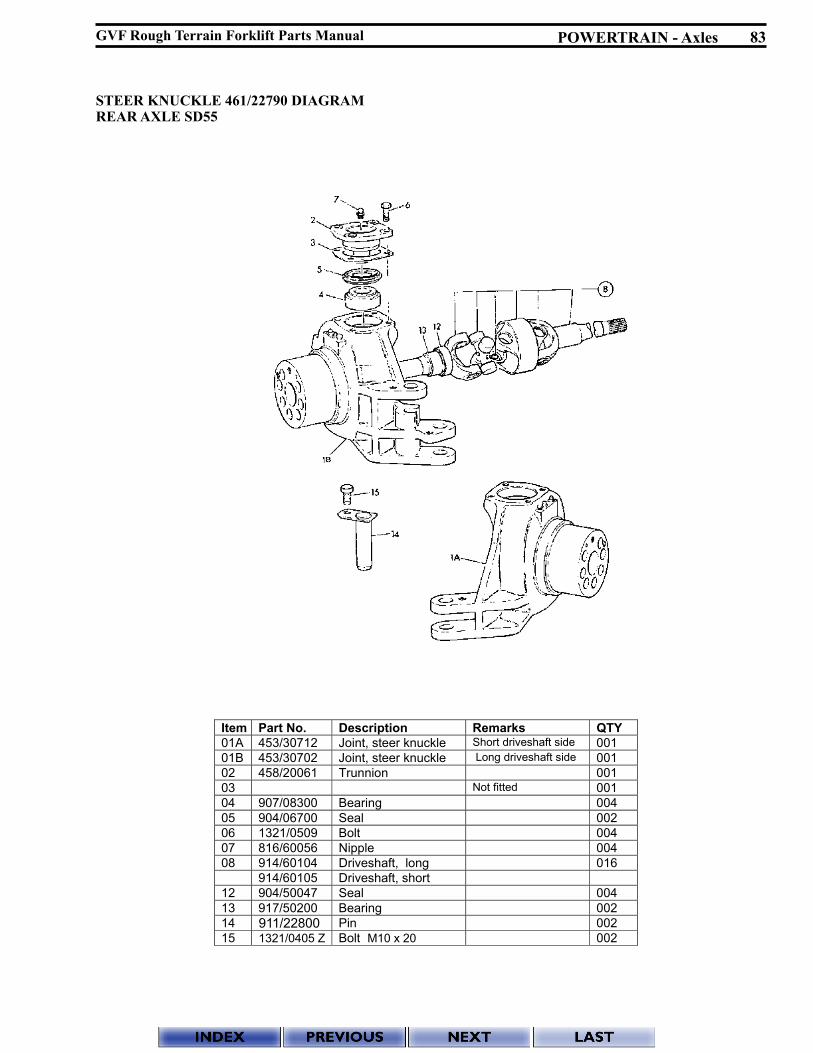
POWERTRAIN - Axles 83GVF Rough Terrain Forklift Parts Manual
STEER KNUCKLE 461/22790 DIAGRAMREAR AXLE SD55 AXLE SD55, STEER KNUCKLE, 461/22790
Item Part No. Description Remarks QTY 01A 453/30712 Joint, steer knuckle Short driveshaft side 001 01B 453/30702 Joint, steer knuckle Long driveshaft side 001 02 458/20061 Trunnion 001 03 Not fitted 001 04 907/08300 Bearing 004 05 904/06700 Seal 002 06 1321/0509 Bolt 004 07 816/60056 Nipple 004 08 914/60104 Driveshaft, long 016 914/60105 Driveshaft, short 12 904/50047 Seal 004 13 917/50200 Bearing 002 14 Pin Not included 002 15 Bolt Not included 002
AXLE SD55, STEER KNUCKLE, 461/22790
Item Part No. Description Remarks QTY 01A 453/30712 Joint, steer knuckle Short driveshaft side 001 01B 453/30702 Joint, steer knuckle Long driveshaft side 001 02 458/20061 Trunnion 001 03 Not fitted 001 04 907/08300 Bearing 004 05 904/06700 Seal 002 06 1321/0509 Bolt 004 07 816/60056 Nipple 004 08 914/60104 Driveshaft, long 016 914/60105 Driveshaft, short 12 904/50047 Seal 004 13 917/50200 Bearing 002 14 Pin Not included 002 15 Bolt Not included 002
911/228001321/0405 Z M10 x 20
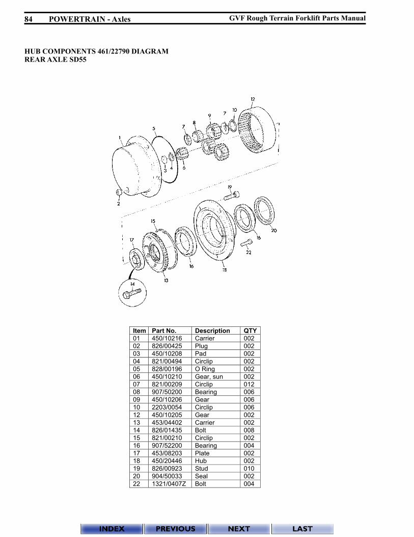
POWERTRAIN - Axles84 GVF Rough Terrain Forklift Parts Manual
HUB COMPONENTS 461/22790 DIAGRAMREAR AXLE SD55
AXLE SD55, HUB COMPONENTS, 461/22790
Item Part No. Description QTY01 450/10216 Carrier 002 02 826/00425 Plug 002 03 450/10208 Pad 002 04 821/00494 Circlip 002 05 828/00196 O Ring 002 06 450/10210 Gear, sun 002 07 821/00209 Circlip 012 08 907/50200 Bearing 006 09 450/10206 Gear 006 10 2203/0054 Circlip 006 12 450/10205 Gear 002 13 453/04402 Carrier 002 14 826/01435 Bolt 008 15 821/00210 Circlip 002 16 907/52200 Bearing 004 17 453/08203 Plate 002 18 450/20446 Hub 002 19 826/00923 Stud 010 20 904/50033 Seal 002 22 1321/0407Z Bolt 004
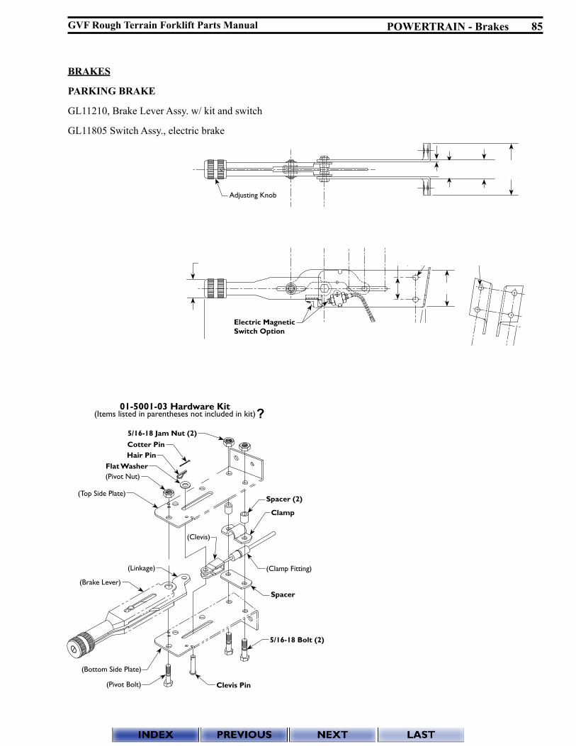
POWERTRAIN - Brakes 85GVF Rough Terrain Forklift Parts Manual
17
Model �06 Over-Center Brake Lever
All dimensions are inches (mm)
• Flange mount for bulkhead, floor or island (dog house) installation.
• Use clamp-type conduit fittings (See page 8) on the end of the cable that attaches to the brake lever.
• 2.5 inches (64mm) wide side plates with single position for attaching one brake cable assembly.
• Electric Switch Option (See page 30)
21-2406-01 (.125)21-2406-03 (.187)
21-1086-28 (.125)21-1086-39 (.187)
22-2121-01 (.125)22-2121-09 (.187)
2.58 (65.5)
-A-
Hole for 5/16 (7.9) Dia Pin
Dimension 2.58 (65.5) depicts length when lever is in "OFF" position. These dimensions are used to calculate cable assembly length.
9°
.12 (3.0)
3.41 (86.6)
1.15(29.2)
(2) Holes for 5/16 (7.9)Dia Bolt, Both Plates
(4) Holes for 5/16 (7.9)Dia Bolts
.91 (23.1)
4.14 (105.2)
2.46 (62.5)
1.25 (31.7) Dia
5.00 (127.0)
1.50(38.1)
6.22 (158.0)
6.82 (173.2)
2.50 (63.5)
.52 (13.2)
.50 (12.7)
2.31 (58.7)
-A-Adjusting Knob
1.50(38.1)
Typical Applications and Features
01-5001-0� Hardware Kit(Items listed in parentheses not included in kit)
8.20(208.3) Standard Lever12.12 (307.8) Long Lever
Recommended components for mounting brake cable with this brake lever assembly
NOTE:
5/16-18 Jam Nut (�)Cotter PinHair Pin
Flat Washer(Pivot Nut)
Spacer (�)
Clamp
(Clevis)
(Clamp Fitting)
Spacer
5/16-18 Bolt (�)
Clevis Pin(Pivot Bolt)
(Bottom Side Plate)
(Linkage)
(Top Side Plate)
(Brake Lever)
Electric Magnetic Switch Option
?
BRAKES
PARKING BRAKE
GL11210, Brake Lever Assy. w/ kit and switch
GL11805 Switch Assy., electric brake
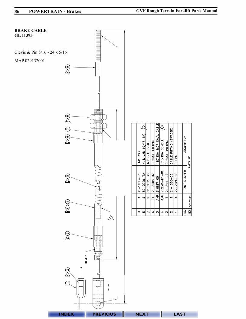
POWERTRAIN - Brakes86 GVF Rough Terrain Forklift Parts Manual
BRAKE CABLE GL 11395
Clevis & Pin 5/16 - 24 x 5/16
MAP 029132001
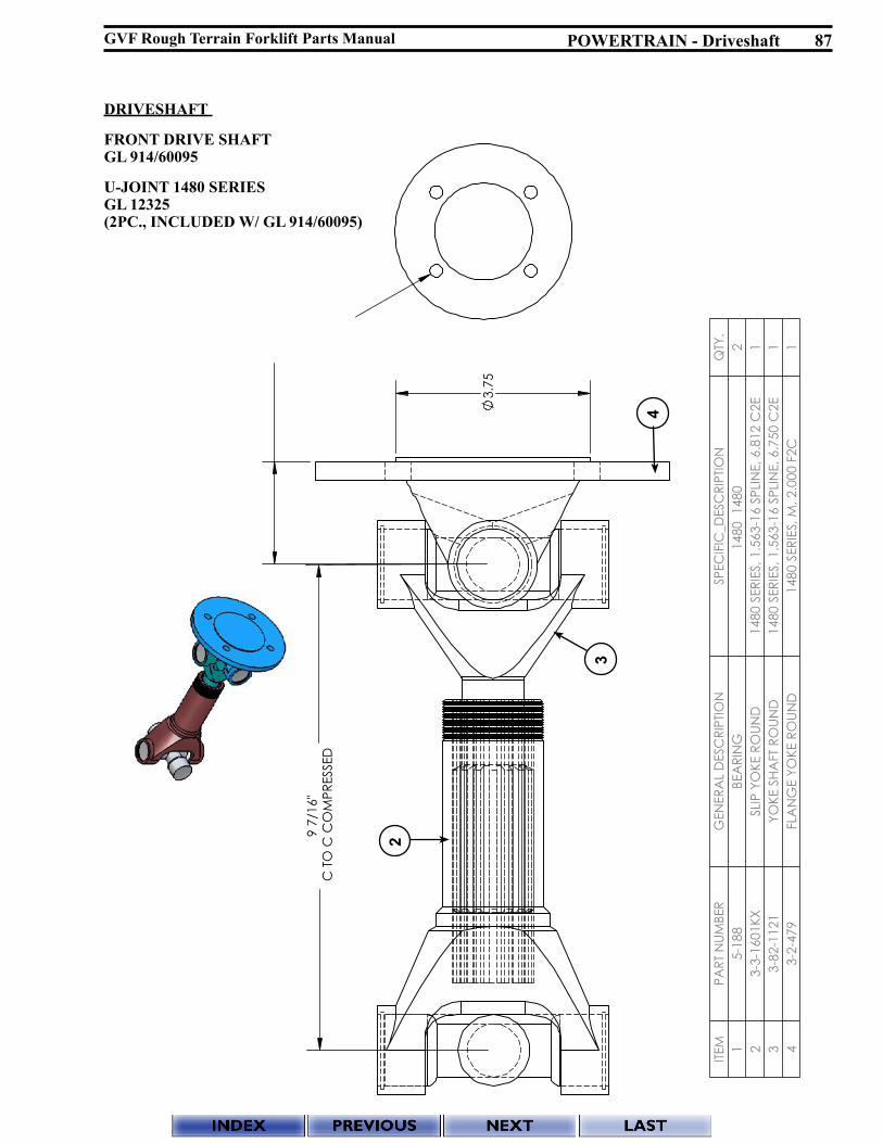
POWERTRAIN - Driveshaft 87GVF Rough Terrain Forklift Parts Manual
9 7/
16"
C T
O C
CO
MPR
ESSE
D
2.00
3.75
CO
NTR
OLL
ING
DIM
ENSI
ON
10.5
0" C
2C M
ID S
LIP
.50
ON
4.7
5" B
/C14
80 P
ATT
ERN
ASSE
MBL
YG
REA
SE S
PLIN
ED
UST C
AP
TIGHT
SLIP
YO
KE M
OVE
S FR
EELY
CHE
CK
PHA
SIN
G W
ITHIN
1.5
°ZE
RKS
INST
ALL
ED IN
LIN
EC
ROSS
& B
RGS
MO
VE F
REEL
YFI
NA
L Q
UALIT
Y C
ON
TRO
L C
HEC
K
SHIP
PING
TAG
DRI
VELIN
E W
ITH C
USTO
MER
PA
RT #
TBA
WRA
P O
UTBO
ARD
BEA
RIN
G C
APS
FO
R SH
IPPI
NG
ITEM
PART
NUM
BER
GEN
ERA
L D
ESC
RIPT
ION
SPEC
IFIC
_DES
CRI
PTIO
NQ
TY.
15-
188
BEA
RIN
G14
80 1
480
22
3-3-
1601
KXSL
IP Y
OKE
RO
UND
1480
SER
IES,
1.5
63-1
6 SP
LINE,
6.8
12 C
2E1
33-
82-1
121
YOKE
SHA
FT R
OUN
D14
80 S
ERIE
S, 1
.563
-16
SPLIN
E, 6
.750
C2E
14
3-2-
479
FLA
NG
E YO
KE R
OUN
D14
80 S
ERIE
S, M
, 2.0
00 F
2C1
Prop
Sha
ft Su
pply
Inc.
DO
NO
T S
CA
LE D
RAW
ING
UNLE
SS O
THER
WIS
E SP
ECIF
IED
DIM
ENSI
ON
S A
RE IN
INC
HES
FRA
CTIO
NS
1/16
X.XX
: .0
20X.
XXX:
.0
10A
NG
ULA
R:
1.5°
SURF
AC
E:
NA
ME
DA
TE
DRA
WN
BY
CHE
CK
BY
SHEE
T 1 O
F 1
REVI
SIO
N D
ESC
RIPT
ION
REV.
DA
TE
PRO
PRIE
TARY
AN
D C
ON
FIDE
NTIA
L
3/17
/07
NEW
A B---
---
C --
- --
-
DRA
WIN
G F
ILE N
AM
E: S
:\PR
INT D
ATA
SHE
ET\N
EW P
SS P
RIN
TS\1
2471
7
JPB
PART
FILE
NA
ME:
S:\
PRIN
T DA
TA S
HEET
\PA
P\SW
\Ass
embl
ies\
SHO
RT C
OUP
LED
RO
UND
\124
717
THE
INFO
RMA
TION
CO
NTA
INED
IN TH
IS D
RAW
ING
IS TH
E SO
LE P
ROPE
RTY
OF
PRO
P SH
AFT
SUP
PLY
INC
.A
NY
REP
ROD
UCTIO
N IN
PA
RT O
R A
S A
WHO
LEW
ITHO
UT TH
E W
RITT
EN P
ERM
ISSI
ON
OF
PRO
P SH
AFT
SUP
PLY
INC
. IS
PRO
HIBI
TED
.
---
---
D --
-
3/17
/07
TITLE
: 14
80 S
HORT
CO
UPLE
DN
OTE
S: 1
480
SHO
RT C
OUP
LED
PSS
REF
#:
1247
17C
USTO
MER
: G
ILLIS
ON
'SC
USTO
MER
PA
RT #
: TB
A
REV:
LA
ST M
OD
IFIE
D:
Satu
rday
, Mar
ch 1
7, 2
007
2:08
:40
PM
1247
17--
--
1247
17
WEI
GHT
: 18
.99
lbs
DRIVESHAFT
FRONT DRIVE SHAFT GL 914/60095
U-JOINT 1480 SERIES GL 12325 (2PC., INCLUDED W/ GL 914/60095)
2
3
4
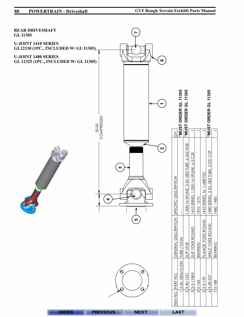
POWERTRAIN - Driveshaft88 GVF Rough Terrain Forklift Parts Manual
20.0
0C
OM
PRES
SED
1.69
2.75
CO
NTR
OLIN
G D
IMEN
TION
IS 2
1" C
2C M
ID S
LIP
ITEM
NO
.PA
RT N
O.
GEN
ERA
L D
ESC
RIPT
ION
SPEC
IFIC
DES
CRI
PTIO
NQ
TY.
13.
50-.0
83x1
0.53
0TU
BE /
DO
M---
12
3-40
-153
1SL
IP S
TUB
1.50
0-16
SPL
INE,
3.5
0-.0
83 T
UBE,
6.5
62 W
2E1
33-
3-11
8KX
SLIP
YO
KE R
OUN
D14
10 S
ERIE
S, 1
.500
-16
SPLI
NE,
6.5
C2E
14
5-16
0BE
ARI
NG
1410
141
0 1
53-
2-15
9FL
AN
GE
YOKE
RO
UND
1410
SER
IES,
M, 1
.688
F2C
16
3-28
-537
WEL
D Y
OKE
RO
UND
1480
SER
IES,
3.5
0-.0
83 T
UBE,
2.0
31 C
2F1
75-
188
BEA
RIN
G14
80 1
480
1
.44
ON
3.7
5" B
/C14
10 P
ATT
ERN
ASSE
MBL
YPR
E-W
ELD
TUB
E A
SSSY
LEN
GTH
CO
RREC
TZE
RKS
INST
ALL
ED IN
LIN
EC
ROSS
& B
RGS
MO
VE
FREE
LYD
UST
CA
P TIG
HTSL
IP Y
OKE
MO
VES
FRE
ELY
FIN
AL
QUA
LITY
CO
NTR
OL
CHE
CK
CHE
CK
PHA
SIN
G W
ITHIN
1.5
°G
REA
SE S
PLIN
E FO
R SH
IPPI
NG
ON
LY
WEL
DER
T.I.R
. ON
NEC
K O
F ST
UB W
ITHIN
.OO
5T.I
.R. O
N TU
BIN
G W
ITHIN
.015
SHIP
PING
LOO
SE H
ARD
WA
RE IN
BA
GS
TAG
DRI
VEL
INE
WITH
CUS
TOM
ER P
ART
# T
BA
Prop
Sha
ft Su
pply
Inc.
MA
TERI
AL:
DO
NO
T S
CA
LE D
RAW
ING
UNLE
SS O
THER
WIS
E SP
ECIF
IED
DIM
ENSI
ON
S A
RE IN
INC
HES
FRA
CTIO
NS
1/16
X.XX
: .0
20X.
XXX:
.0
10A
NG
ULA
R:
1.5°
SURF
AC
E:
NA
ME
DA
TE
DRA
WN
BY
CHE
CK
BY
SHEE
T 1 O
F 1
REVI
SIO
N D
ESC
RIPT
ION
REV.
DA
TE
PRO
PRIE
TARY
AN
D C
ON
FIDE
NTIA
L
3/17
/07
NEW
A B
C
TITLE
: 14
10X1
480D
OUB
LE J
OIN
T WITH
SLIP
NO
TES:
141
0 X
1480
21"
C2C
MS
PSS
PART
#:
1247
18PS
S FI
LE #
: 12
4718
CUS
TOM
ER:
GILL
ISO
N'S
CUS
TOM
ER P
ART
#:
TBA
CRE
ATE
D:
Wed
nesd
ay, J
uly
23, 2
003
12:5
8:18
PM
LAST
MO
DIF
IED
: Sa
turd
ay, M
arch
17,
200
7 2:
02:1
6 PM
WEI
GHT
: 24
.58
lbs
DRA
WIN
G F
ILE N
AM
E: S
:\PR
INT
DA
TA S
HEET
\NEW
PSS
PRI
NTS
\124
718
JPB
PART
FILE
NA
ME:
S:\
PRIN
T D
ATA
SHE
ET\P
AP\
SW\A
ssem
blie
s\D
AN
A D
OUB
LE J
OIN
T\12
4718
QTY
:
THE
INFO
RMA
TION
CO
NTA
INED
IN T
HIS
DRA
WIN
GIS
THE
SO
LE P
ROPE
RTY
OF
PRO
P SH
AFT
SUP
PLY
INC
.A
NY
REP
ROD
UCTIO
N IN
PA
RT O
R A
S A
WHO
LEW
ITHO
UT T
HE W
RITT
EN P
ERM
ISSI
ON
OF
PRO
P SH
AFT
SUP
PLY
INC
. IS
PRO
HIBI
TED
.
JJA
1/16
/200
6
12
3
4
5
6
7
*MU
ST O
RD
ER G
L 11
305
*MU
ST O
RD
ER G
L 11
305
*MU
ST O
RD
ER G
L 11
305
REAR DRIVESHAFT GL 11305
U-JOINT 1410 SERIES GL12330 (1PC., INCLUDED W/ GL 11305)
U-JOINT 1480 SERIES GL 12325 (1PC., INCLUDED W/ GL 11305)
POWERTRAIN - Tires 89GVF Rough Terrain Forklift Parts Manual
TIRES
GL 11130 12.5/80-18 10 PLY.
GL 11135 16.9 X 24 10 PLY.

POWERTRAIN - Transmission90 GVF Rough Terrain Forklift Parts Manual
TRANSMISSION
SS700 4WD, 460/60050 DIAGRAM
TRANSMISSION, SS700 4WD, 460/60050 Item Part No. Description QTY01 459/30464 Housing 1 02 459/30439 Casing 1 03 459/70382 Casing 1 04 826/01417 Bolt 18 05 445/14001 Dowel 2 06 1315/0409Z Screw 12 07 445/14001 Dowel 2 08 1606/0017 Adapter 2 09 1406/0018 Seal 4 10 816/80041 Plug 3 11 814/00222 Spring 1 12 916/00008 Bearing 2 13 816/80041 Plug 2 14 32/902200 Strainer 1 15 813/50027 Gasket 1 16 828/10222 O Ring 2 18 1406/0011 Seal 2 19 45/905000 Adapter 1 20 813/50027 Gasket 1 21 1321/0303Z Screw 2 22 816/15184 Adapter 1 23 581/18076 Element 1 24 813/10175 Gasket 1 25 459/10144 Valve 1 26 814/00412 Spring 1 27 816/80063 Plug 1 28 1392/3207 Capscrew 4 29 1391/3108Z Capscrew 4 30 25/220998 Valve 1 30A 25/221054 Coil 1 31 35/100801 Kit-seal 1 32 816/80041 Plug 1 35 701/80459 Switch 1 35A 1406/0011 Seal 1 Item Part No. Description QTY40 813/50041 Seal 1 41 25/220804 Valve 1 43 830/12564 Pipe 1 44 816/80061 Plug 1 45 814/10170 Spring 1 46 459/70168 Spool 1 51 816/82009 Plug 1 52 826/10707 Screw 1 53 816/80051 Plug 2
701/80626
459/m2874
TRANSMISSION, SS700 4WD, 460/60050 Item Part No. Description QTY01 459/30464 Housing 1 02 459/30439 Casing 1 03 459/70382 Casing 1 04 826/01417 Bolt 18 05 445/14001 Dowel 2 06 1315/0409Z Screw 12 07 445/14001 Dowel 2 08 1606/0017 Adapter 2 09 1406/0018 Seal 4 10 816/80041 Plug 3 11 814/00222 Spring 1 12 916/00008 Bearing 2 13 816/80041 Plug 2 14 32/902200 Strainer 1 15 813/50027 Gasket 1 16 828/10222 O Ring 2 18 1406/0011 Seal 2 19 45/905000 Adapter 1 20 813/50027 Gasket 1 21 1321/0303Z Screw 2 22 816/15184 Adapter 1 23 581/18076 Element 1 24 813/10175 Gasket 1 25 459/10144 Valve 1 26 814/00412 Spring 1 27 816/80063 Plug 1 28 1392/3207 Capscrew 4 29 1391/3108Z Capscrew 4 30 25/220998 Valve 1 30A 25/221054 Coil 1 31 35/100801 Kit-seal 1 32 816/80041 Plug 1 35 701/80459 Switch 1 35A 1406/0011 Seal 1
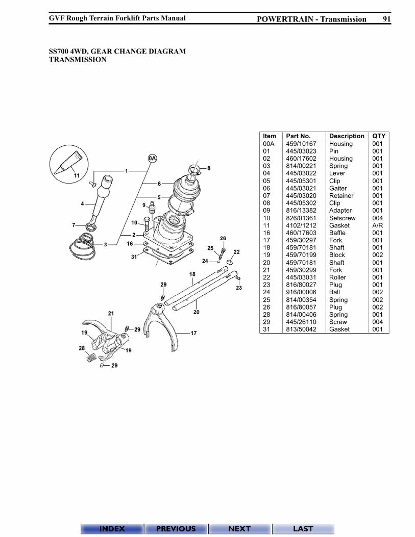
POWERTRAIN - Transmission 91GVF Rough Terrain Forklift Parts Manual
SS700 4WD, GEAR CHANGE DIAGRAMTRANSMISSION
TRANSMISSION, SS700 4WD, GEAR CHANGE Item Part No. Description QTY00A 459/10167 Housing 001 01 445/03023 Pin 001 02 460/17602 Housing 001 03 814/00221 Spring 001 04 445/03022 Lever 001 05 445/05301 Clip 001 06 445/03021 Gaiter 001 07 445/03020 Retainer 001 08 445/05302 Clip 001 09 816/13382 Adapter 001 10 826/01361 Setscrew 004 11 4102/1212 Gasket A/R 16 460/17603 Baffle 001 17 459/30297 Fork 001 18 459/70181 Shaft 001 19 459/70199 Block 002 20 459/70181 Shaft 001 21 459/30299 Fork 001 22 445/03031 Roller 001 23 816/80027 Plug 001 24 916/00006 Ball 002 25 814/00354 Spring 002 26 816/80057 Plug 002 28 814/00406 Spring 001 29 445/26110 Screw 004 31 813/50042 Gasket 001
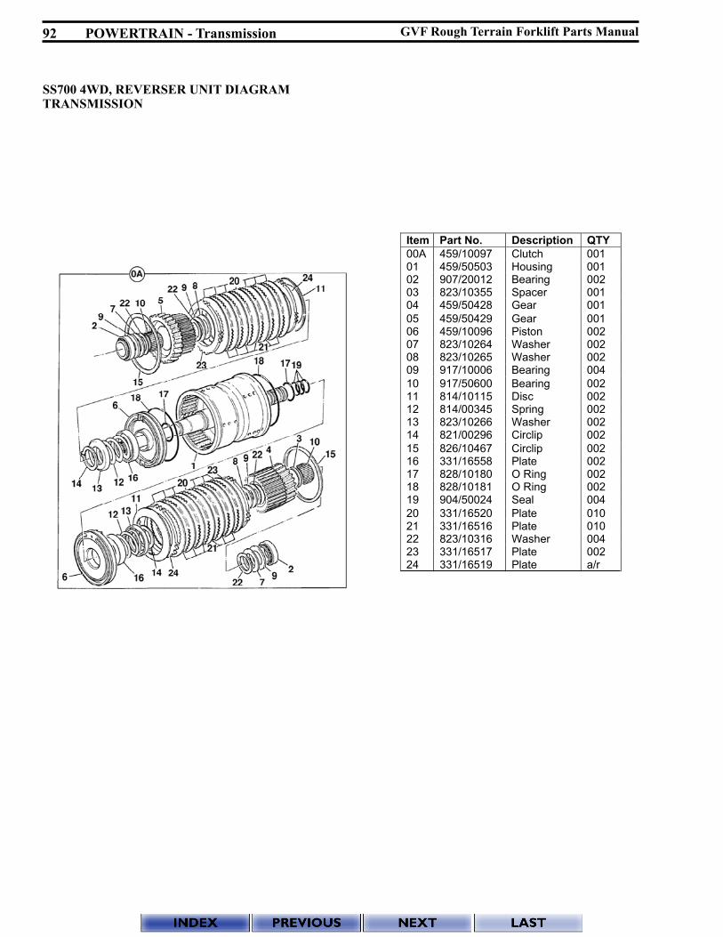
POWERTRAIN - Transmission92 GVF Rough Terrain Forklift Parts Manual
TRANSMISSION, SS700 4WD, REVERSER UNIT Item Part No. Description QTY 00A 459/10097 Clutch 001 01 459/50503 Housing 001 02 907/20012 Bearing 002 03 823/10355 Spacer 001 04 459/50428 Gear 001 05 459/50429 Gear 001 06 459/10096 Piston 002 07 823/10264 Washer 002 08 823/10265 Washer 002 09 917/10006 Bearing 004 10 917/50600 Bearing 002 11 814/10115 Disc 002 12 814/00345 Spring 002 13 823/10266 Washer 002 14 821/00296 Circlip 002 15 826/10467 Circlip 002 16 331/16558 Plate 002 17 828/10180 O Ring 002 18 828/10181 O Ring 002 19 904/50024 Seal 004 20 331/16520 Plate 010 21 331/16516 Plate 010 22 823/10316 Washer 004 23 331/16517 Plate 002 24 331/16519 Plate a/r
SS700 4WD, REVERSER UNIT DIAGRAMTRANSMISSION

POWERTRAIN - Transmission 93GVF Rough Terrain Forklift Parts Manual
TRANSMISSION, SS700 4WD, 460/60050 Item Part No. Description Remarks QTY1 460/60050 Gearbox SS700 1 2 459/30463 Casing front 1 3 459/30435 Casing rear 1 4 459/05701 Gear input, 24t 1 5 445/20101 Gear output 1 9 459/10239 Clutch assembly 4WD 1 12 4102/1212 Gasket liquid A/R 13 459/30451 Cover, 4wd 1 14 826/01417 Bolt 10 16 904/20172 Seal 1 17 331/12043 Flange 1 18 823/00328 Washer 1 19 826/00817 Setscrew 1 20 445/14001 Dowel 2 21 823/10582 Washer, thrust Part of item 9 1 22 907/20031 Bearing Part of item 9 2 23 917/02600 Bearing, needle roller Part of item 9 2
TRANSMISSION, SS700 4WD, 460/60050 Item Part No. Description Remarks QTY1 460/60050 Gearbox SS700 1 2 459/30463 Casing front 1 3 459/30435 Casing rear 1 4 459/05701 Gear input, 24t 1 5 445/20101 Gear output 1 9 459/10239 Clutch assembly 4WD 1 12 4102/1212 Gasket liquid A/R 13 459/30451 Cover, 4wd 1 14 826/01417 Bolt 10 16 904/20172 Seal 1 17 331/12043 Flange 1 18 823/00328 Washer 1 19 826/00817 Setscrew 1 20 445/14001 Dowel 2 21 823/10582 Washer, thrust Part of item 9 1 22 907/20031 Bearing Part of item 9 2 23 917/02600 Bearing, needle roller Part of item 9 2
SS700 4WD, 460/60050 DIAGRAMTRANSMISSION

POWERTRAIN - Transmission94 GVF Rough Terrain Forklift Parts Manual
TRANSMISSION, SS700 4WD CLUTCH UNIT Item Part No. Description QTY01 459/10239 Clutch 001 02 445/19802 Housing 001 03 2403/0244 O Ring 002 04 445/15701 Piston 001 05 2403/0221 O Ring 001 06 445/05114 Ring 001 07 445/05118 Disc 002 08 445/19805 Sleeve 002 09 445/19808 Washer 002 10 445/64701 Drum 004 11 821/00447 Circlip 002 12 445/19807 Plate 002 13 445/05106 Plate 002 14 445/05107 Plate 002 15 445/19804 Plate 002 16 445/05110 Disc 002 17 2203/1104 Circlip 002 18 459/50689 Shaft 001 19 904/14300 Seal 001 20 907/20031 Bearing 002 21 823/10582 Washer 001 22 917/02600 Bearing 002
SS700 4WD, CLUTCH UNIT DIAGRAMTRANSMISSION
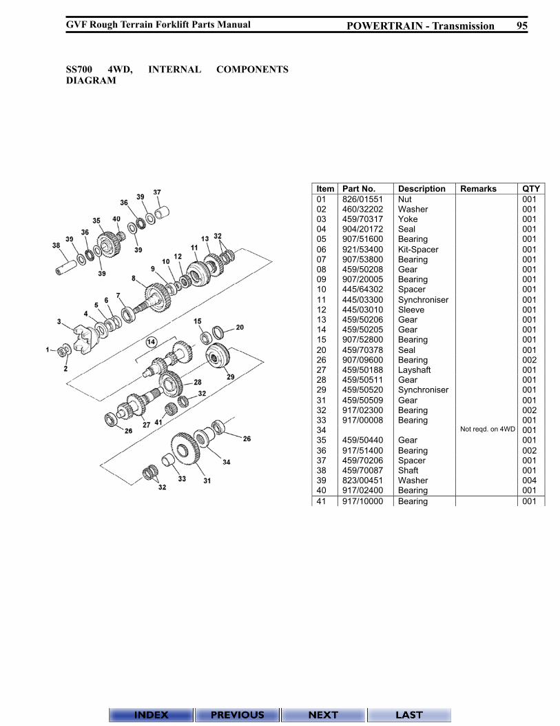
POWERTRAIN - Transmission 95GVF Rough Terrain Forklift Parts Manual
TRANSMISSION, SS700 4WD, INTERNAL COMPONENTS Item Part No. Description Remarks QTY01 826/01551 Nut 001 02 460/32202 Washer 001 03 459/70317 Yoke 001 04 904/20172 Seal 001 05 907/51600 Bearing 001 06 921/53400 Kit-Spacer 001 07 907/53800 Bearing 001 08 459/50208 Gear 001 09 907/20005 Bearing 001 10 445/64302 Spacer 001 11 445/03300 Synchroniser 001 12 445/03010 Sleeve 001 13 459/50206 Gear 001 14 459/50205 Gear 001 15 907/52800 Bearing 001 20 459/70378 Seal 001 26 907/09600 Bearing 002 27 459/50188 Layshaft 001 28 459/50511 Gear 001 29 459/50520 Synchroniser 001 31 459/50509 Gear 001 32 917/02300 Bearing 002 33 917/00008 Bearing 001 34 Not reqd. on 4WD 001 35 459/50440 Gear 001 36 917/51400 Bearing 002 37 459/70206 Spacer 001 38 459/70087 Shaft 001 39 823/00451 Washer 004 40 917/02400 Bearing 001 41 917/10000 Bearing 001
SS700 4WD, INTERNAL COMPONENTS DIAGRAM
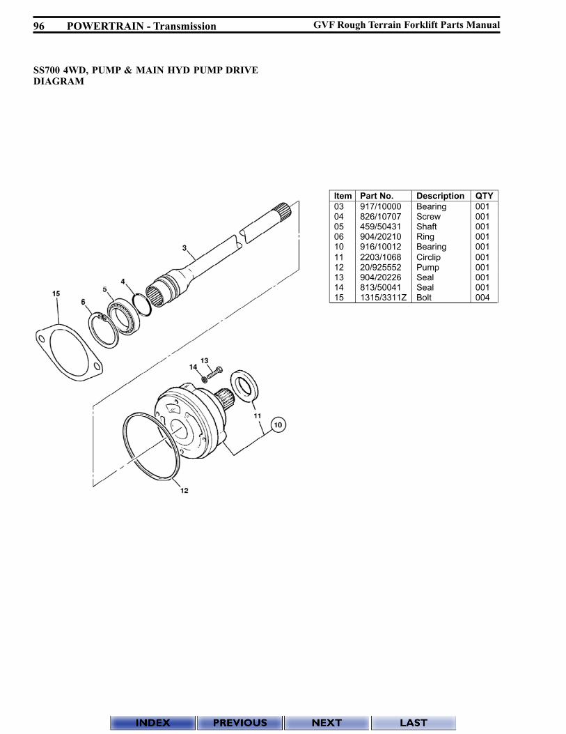
POWERTRAIN - Transmission96 GVF Rough Terrain Forklift Parts Manual
TRANSMISSION, SS700 4WD, PUMP & MAIN HYD PUMP DRIVE Item Part No. Description QTY03 917/10000 Bearing 001 04 826/10707 Screw 001 05 459/50431 Shaft 001 06 904/20210 Ring 001 10 916/10012 Bearing 001 11 2203/1068 Circlip 001 12 20/925552 Pump 001 13 904/20226 Seal 001 14 813/50041 Seal 001 15 1315/3311Z Bolt 004
SS700 4WD, PUMP & MAIN HYD PUMP DRIVE DIAGRAM

POWERTRAIN - Wheels 97GVF Rough Terrain Forklift Parts Manual
WHEEL ASSEMBLY
GL 12220 WHEEL ASSEMBLY, 15 X 24
GL 12215 WHEEL ASSEMBLY 9 X 18

STEERING - Steering Column98 GVF Rough Terrain Forklift Parts Manual
STEERING
STEERING COLUMNGL 11195REPLACEMNET PARTS NOT AVAILABLE USE GL 11195
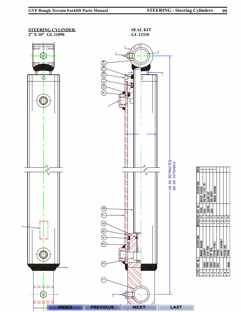
STEERING - Steering Cylinders 99GVF Rough Terrain Forklift Parts Manual
STEERING CYLINDER 2” X 10” GL 11890
SEAL KIT GL 12310
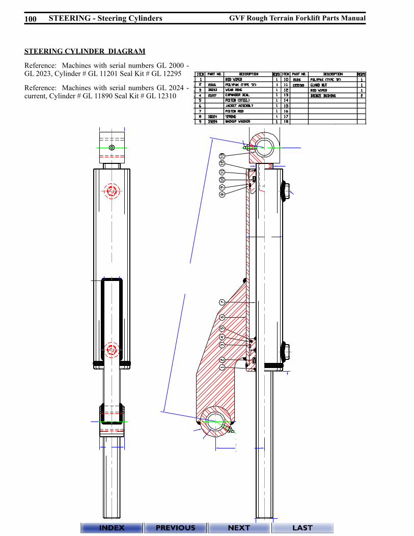
STEERING - Steering Cylinders100 GVF Rough Terrain Forklift Parts Manual
STEERING CYLINDER DIAGRAM
Reference: Machines with serial numbers GL 2000 - GL 2023, Cylinder # GL 11201 Seal Kit # GL 12295
Reference: Machines with serial numbers GL 2024 - current, Cylinder # GL 11890 Seal Kit # GL 12310
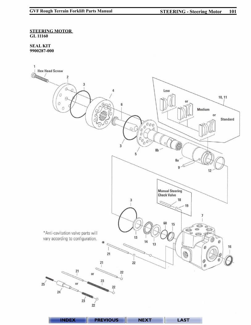
101STEERING - Steering MotorGVF Rough Terrain Forklift Parts Manual
STEERING MOTOR GL 11160
SEAL KIT 9900287-000
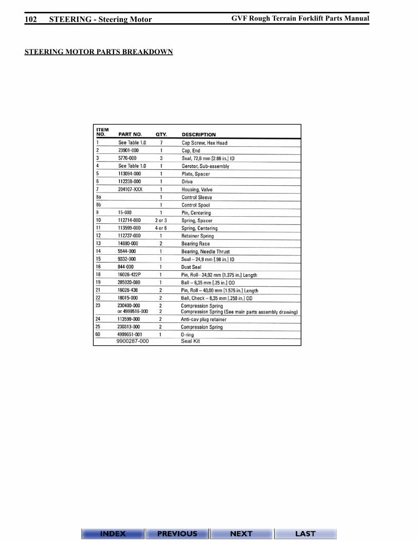
102 STEERING - Steering Motor GVF Rough Terrain Forklift Parts Manual
STEERING MOTOR PARTS BREAKDOWN
9900287-000 Seal Kit