gw-7552 (modbus rtu master) example for simatic step 7 · gw-7552 (modbus rtu master) example for...
TRANSCRIPT

1
GW-7552 (Modbus RTU master)
example for SIMATIC STEP 7
Example 1:Reads DO module data from GW-7552(Modbus FC01).
Example 2: Reads DI module data from GW-7552(Modbus FC02).
Example 3: Reads AO module data from GW-7552(Modbus FC03).
Example 4: Reads AI module data from GW-7552(Modbus FC04).
Example 5: Writes DO module data from GW-7552(Modbus FC05,15).
Example 6: Writes AO module data from GW-7552(Modbus FC06,16).

2
Example 1: PLC reads DO module data from GW-7552.
(Modbus FC01)
Read a Modbus RTU DO module (PROFIBUS Slave & Modbus RTU/Master)
3
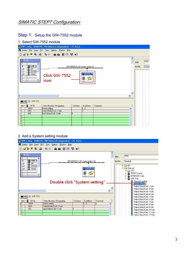
SIMATIC STEP7 Configuration:
Step 1: Setup the GW-7552 module
1. Select GW-7552 module
2. Add a System setting module

4
3. Add “Output Relay/Coil – 1 byte” and “Input Relay/Coil – 1byte”

5
Step 2: Setup the parameters of the GW-7552
1. Double click GW-7552 icon
2. Select “Parameter Assignment”
3. Set common parameters of the GW-7552
Common parameters
Baud rate: 115200; Parity: none; Data: 8 data bit; Stop bit: 1 stop bit; Modbus type: Master
Modbus Format: Modbus RTU; Byte Order: Big Endian

6
4. Set module parameters of the GW-7552
(1)Double click “Output Relay/Coil – 1 byte” module
(2)Select “Parameter Assignment”
5. Setup “Output Relay/Coil – 1 byte” module parameter
Module parameters
Modbus Slave Device ID: 2; Slave Address: 0 (Protocol address (base 0))

7
6. Set module parameters of the GW-7552
(1)Double click “Input Relay/Coil – 1 byte” module
(2)Select “Parameter Assignment”
7. Setup “Input Relay/Coil – 1 byte” module parameter
Module parameters
Modbus Slave Device ID: 2; Slave Address: 0 (Protocol address (base 0))
Module Type: Read DO, click ok.

8
Step 3: Download the HW settings into SIMATIC PLC
1. Save and Compile
2. HW settings into SIMATIC PLC

9
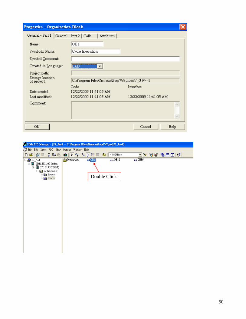
Step 4: Insert a new Organization Block (OB1,OB82,OB86)
\

10
Step 5: Edit OB1
Variables used in the example LD Program:
Double Click

11

12
Step 6: Download the settings into SIMATIC PLC

13
Step 7: Make sure the RUN LED of the GW-7552 is on and the switch of the GW-7552 is at
Normal mode.
Now the setting procedure has been finished and the user can read the data to
the Modbus DO module at address IB0.

14
Example 2: PLC reads DI module data from GW-7552.
(Modbus FC02)
Read a Modbus RTU DI module (PROFIBUS Slave & Modbus RTU/Master)

15
SIMATIC STEP7 Configuration:
Step 1: Setup the GW-7552 module
1. Select GW-7552 module
2. Add a System setting module

16
3. Add “Input Relay/Coil—1 byte” module
Step 2: Setup the parameters of the GW-7552
1. Double click GW-7552 icon
2. Select “Parameter Assignment”

17
3. Set common parameters of the GW-7552
Common parameters
Baud rate: 115200; Parity: none; Data: 8 data bit; Stop bit: 1 stop bit; Modbus type: Master
Modbus Format: Modbus RTU; Byte Order: Big Endian
4. Set module parameters of the GW-7552
(1)Double click “Input Relay/Coil—1 byte” module
(2)Select “Parameter Assignment”
18
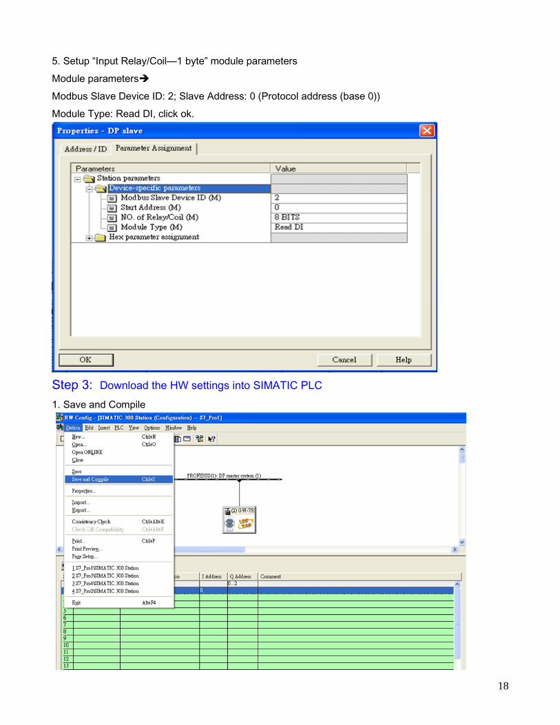
5. Setup “Input Relay/Coil—1 byte” module parameters
Module parameters
Modbus Slave Device ID: 2; Slave Address: 0 (Protocol address (base 0))
Module Type: Read DI, click ok.
Step 3: Download the HW settings into SIMATIC PLC
1. Save and Compile

19
2. HW settings into SIMATIC PLC
Step 4: Insert a new Organization Block (OB1,OB82,OB86)

20
Double Click

21
Step 5: Edit OB1
Step 6: Download the settings into SIMATIC PLC

22
Step 7: Make sure the RUN LED of the GW-7552 is on and the switch of the GW-7552 is at
Normal mode.
Now the setting procedure has been finished and the user can read the data of
the Modbus DI module at address PIB0.

23
Example 3: PLC reads AO module data from GW-7552.
(Modbus FC03)
Read a Modbus RTU AO module (PROFIBUS Slave & Modbus RTU/Master)

24
SIMATIC STEP7 Configuration:
Step 1: Setup the GW-7552 module
1. Select GW-7552 module
2. Add a System setting module

25
3. Add “Onput Register – 1 word” and “Input Register – 1 word”

26
Step 2: Setup the parameters of the GW-7552
1. Double click GW-7552 icon
2. Select “Parameter Assignment”
3. Set common parameters of the GW-7552
Common parameters
Baud rate: 115200; Parity: none; Data: 8 data bit; Stop bit: 1 stop bit; Modbus type: Master
Modbus Format: Modbus RTU; Byte Order: Big Endian

27
4. Set module parameters of the GW-7552
(1)Double click “Output Register – 1 word” module
(2)Select “Parameter Assignment”
5. Setup “Output Register – 1 word” module parameters
Module parameters
Modbus Slave Device ID: 2; Slave Address: 0 (Protocol address (base 0)), click ok.

28
6. Set module parameters of the GW-7552
(1)Double click “Intput Register – 1 word” module
(2)Select “Parameter Assignment”
5. Setup “Input Register – 1 word” module parameters
Module parameters
Modbus Slave Device ID: 2; Slave Address: 0 (Protocol address (base 0)), click ok.
Module Type: Read AO, click ok.

29
Step 3: Download the HW settings into SIMATIC PLC
1. Save and Compile
2. HW settings into SIMATIC PLC

30
Step 4: Insert a new Organization Block (OB1,OB82,OB86)

31
Step 5: Edit OB1
Variables used in the example LD Program:
Double Click

32

33
Step 6: Download the settings into SIMATIC PLC

34
Step 7: Make sure the RUN LED of the GW-7552 is on and the switch of the GW-7552 is at
Normal mode.
Now the setting procedure has been finished and the user can write the data to
the Modbus AO module at address PIW256.

35
Example 4: PLC reads AI module data from GW-7552.
(Modbus FC04)
Read a Modbus RTU AI module (PROFIBUS Slave & Modbus RTU/Master)
1

36
SIMATIC STEP7 Configuration:
Step 1: Setup the GW-7552 module
1. Select GW-7552 module
2. Add a System setting module

37
3. Add “Input Register—1 word” module
Step 2: Setup the parameters of the GW-7552
1. Double click GW-7552 icon
2. Select “Parameter Assignment”

38
3. Set common parameters of the GW-7552
Common parameters
Baud rate: 115200; Parity: none; Data: 8 data bit; Stop bit: 1 stop bit; Modbus type: Master
Modbus Format: Modbus RTU; Byte Order: Big Endian
4. Set module parameters of the GW-7552
(1)Double click “input register—1 word” module
(2)Select “Parameter Assignment”

39
5. Setup “input register—1 word” module parameters
Module parameters
Modbus Slave Device ID: 1; Slave Address: 0 (Protocol address (base 0))
Module Type: Read AI, click ok.
Step 3: Download the HW settings into SIMATIC PLC
1. Save and Compile

40
2. HW settings into SIMATIC PLC
Step 4: Insert a new Organization Block (OB1,OB82,OB86)

41
Double Click
42
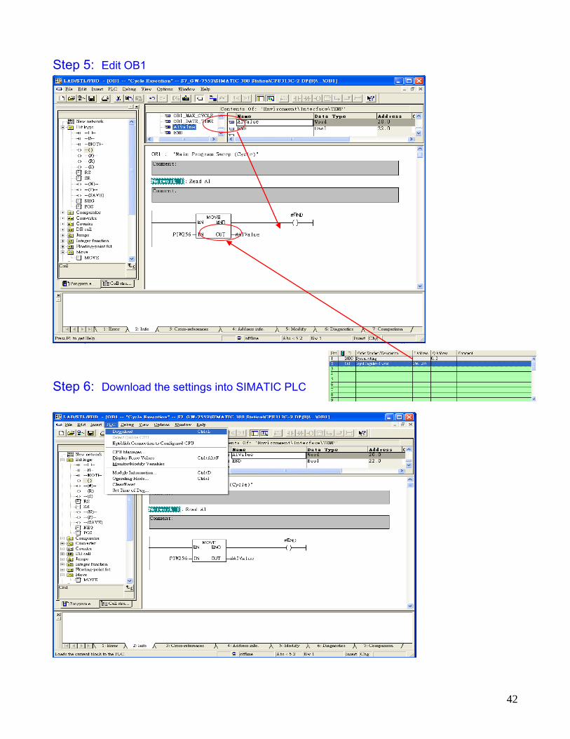
Step 5: Edit OB1
Step 6: Download the settings into SIMATIC PLC

43
Step 7: Make sure the RUN LED of the GW-7552 is on and the switch of the GW-7552 is at
Normal mode.
Now the setting procedure has been finished and the user can read the data of
the Modbus AI module at address PIW256.
44
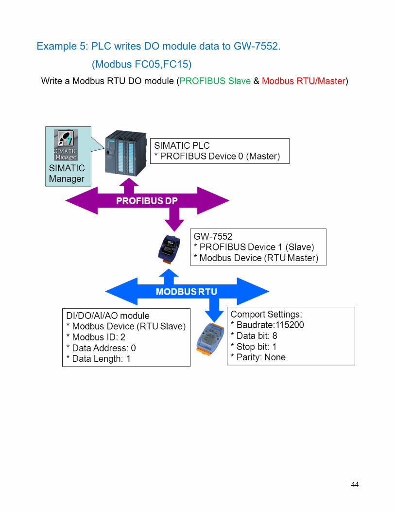
Example 5: PLC writes DO module data to GW-7552.
(Modbus FC05,FC15)
Write a Modbus RTU DO module (PROFIBUS Slave & Modbus RTU/Master)

45
SIMATIC STEP7 Configuration:
Step 1: Setup the GW-7552 module
1. Select GW-7552 module
2. Add a System setting module

46
3. Add “Onput Relay/Coil—1 byte” module(For FC15,multiple coils, please select more than 1 byte
module)
Step 2: Setup the parameters of the GW-7552
1. Double click GW-7552 icon
2. Select “Parameter Assignment”

47
3. Set common parameters of the GW-7552
Common parameters
Baud rate: 115200; Parity: none; Data: 8 data bit; Stop bit: 1 stop bit; Modbus type: Master
Modbus Format: Modbus RTU; Byte Order: Big Endian
4. Set module parameters of the GW-7552
(1)Double click “Output Relay/Coil—1 byte” module
(2)Select “Parameter Assignment”

48
5. Setup “Output Relay/Coil—1 byte” module parameters
Module parameters
Modbus Slave Device ID: 2; Slave Address: 0 (Protocol address (base 0)), click ok.
Step 3: Download the HW settings into SIMATIC PLC
1. Save and Compile

49
2. HW settings into SIMATIC PLC
Step 4: Insert a new Organization Block (OB1,OB82,OB86)
50
Double Click

51
Step 5: Edit OB1
Variables used in the example LD Program:

52

53
Step 6: Download the settings into SIMATIC PLC
Step 7: Make sure the RUN LED of the GW-7552 is on and the switch of the GW-7552 is at
Normal mode.

54
Now the setting procedure has been finished and the user can write the data to
the Modbus DO module at address QB3.

55
Example 6: PLC writes AO module data to GW-7552.
(Modbus FC06, FC16)
Write a Modbus RTU AO module (PROFIBUS Slave & Modbus RTU/Master)

56
SIMATIC STEP7 Configuration:
Step 1: Setup the GW-7552 module
1. Select GW-7552 module
2. Add a System setting module

57
3. Add “Output Register—1word” module. (For FC16,multiple registers, please select more than 1
word module)
Step 2: Setup the parameters of the GW-7552
1. Double click GW-7552 icon
2. Select “Parameter Assignment”
58
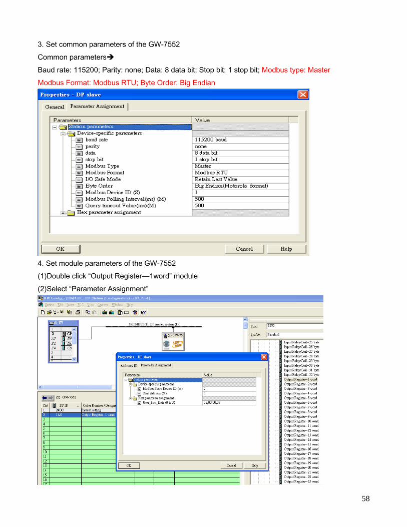
3. Set common parameters of the GW-7552
Common parameters
Baud rate: 115200; Parity: none; Data: 8 data bit; Stop bit: 1 stop bit; Modbus type: Master
Modbus Format: Modbus RTU; Byte Order: Big Endian
4. Set module parameters of the GW-7552
(1)Double click “Output Register—1word” module
(2)Select “Parameter Assignment”

59
5. Setup “Output Register—1 word” module parameters
Module parameters
Modbus Slave Device ID: 2; Slave Address: 0 (Protocol address (base 0)), click ok.
Step 3: Download the HW settings into SIMATIC PLC
1. Save and Compile

60
2. HW settings into SIMATIC PLC
Step 4: Insert a new Organization Block (OB1,OB82,OB86)

61
Double Click

62
Step 5: Edit OB1
Variables used in the example LD Program:

63
Using T2 trigger T1 If counter (C1) add 1 and Tri will add 1 every 1s.
If Tri is equal to 256 then reset counter (C1).

64
Step 6: Download the settings into SIMATIC PLC
Step 7: Make sure the RUN LED of the GW-7552 is on and the switch of the GW-7552 is at
Normal mode.

65
Now the setting procedure has been finished and the user can write the data to
the Modbus AO module at address PQW256.