gwb rus prav - Подшипники в компании ...mialin.ru/file/catalog/gwb rus.pdf ·...
TRANSCRIPT

��������� ����� �������
Cardan Shaftsfor Industrial Applications
SPICER GELENKWELLENBAU
GWB_Rus_prav.qxd 5/4/08 6:17 PM Page 1

�������� ���� Spicer Gelenkwellenbau GmbH
� ����: GK Marketing Service GmbH
�� ���� ��������.���� � ���� ������ ��� ��� � � ����� �� ���� ���� ������ ������ � �������������.
����!� � �� ��������" ���. #������� �� ������������ ��������"�� ������ � ��� � ��������� �"��� � � STD 1016-005.
������ ������� ��"$�� �� �����$ ����� .%� �������" �� ����� ���� �� �"�� .
&������� � '�"�� 2006
Copyright by Spicer Gelenkwellenbau GmbH
Design: GK Marketing Service GmbH
All rights reserved.Any reproduction of this publication or parts thereof is subject to theexplicit authorization of the copyright-holder.
Regulation concerning Copyright.Productliability and Safety-Directions see STD 1016-000.
This catalogue supersedes all former editions.We reserve the right to make alterations.
Printed in Germany 2006
�������� ����/Postal address:P.O. Box 10 13 62
45013 Essen/Germany
���� �( ��/Office address:Westendhof 5-9
45143 Essen/Germany
Tel.: 00 49 (0) 2 01 – 81 24-0
Fax: 00 49 (0) 2 01 – 81 24-652
E-Mail: [email protected]
Web: http://www.gwb-essen.de
SPICER GELENKWELLENBAU
éÙˈˇθÌ˚È Ô‰ÒÚ‡‚ËÚÂθ ‚ Òڇ̇ı ëçÉAPA-KANDT GmbH
Weidestrasse 122 a22083 Hamburg
ÚÂÎ: +49 40 80 614 38Ù‡ÍÒ +49 40 80 614 938E-Mail: [email protected]: www.apa-kandt.de
GWB_Rus_prav.qxd 5/4/08 6:17 PM Page 2

1
���������� Table of Contents
ëÔˆˇÎËÒÚ˚ ‚ ӷ·ÒÚË ÔË‚Ó‰ÌÓÈ ÚÂıÌËÍË )���� �� 2
����� ����� ��������� �� )���� �� 4
���������� ������ ��������� ��� ������������� ����������� )���� �� 8
���������� �� ��������! �� �����"������ � )���� �� 10
#�� ��� ��� ������ )���� �� 11
�����"������
! )� � 687/688 )���� �� 14
! )� � 587 )���� �� 18
! )� � 390 )���� �� 20
! )� � 392/393 )���� �� 22
! )� � 492 )���� �� 24
! )� � 498 )���� �� 26
! )� � 587/190 ���������� � � ���� )���� �� 28
! *��������+�"�� "�(��)� � 330 )���� �� 30
! *��������+�"�� "�(��)� � 230 )���� �� 31
! )����� �������� ������ �� )���� �� 32
! ,������ ��� �� � ���-�" )���� �� 33
! ;����� <��������� �� 687/688/587/390 )���� �� 34
! )��������� ��� � ��-�� (����� )���� �� 35
#�� ��� ��� ������ )���� �� 36
����������� ����������� )���� �� 40
������� �������$����� �������� )���� �� 42
%����$����� �������� ��� ������ )���� �� 44
&���� ��������� �� )���� �� 54
'������� � �����$����� ���������� )���� �� 57
�ÌÒÚÛ͈Ëfl ÔÓ ÙÓÏËÓ‚‡Ì˲ Á‡fl‚ÍË )���� �� 68
�������� ���������� )���� �� 69
We are the experts
in transmission engineering Page 2
Survey of cardan shaft series Page 4
Special designs of cardan shafts
and additional equipment Page 8
Directions for handling of data sheets Page 10
Application examples Page 11
Data sheets
! Series 687/688 Page 14! Series 587 Page 18! Series 390 Page 20! Series 392/393 Page 22! Series 492 Page 24! Series 498 Page 26! Series 587/190 super short designs Page 28! Quick release couplings
Series 330 Page 30! Quick release couplings
Series 230 Page 31! Journal cross assemblies Page 32! Flange connection
with serration Page 33! Face key connection
Series 687/688/587/390 Page 34! Standard companion flanges Page 35
Application examples Page 36
Design features Page 40
General theoretical directions Page 42
Technical directions for application Page 44
Selection of cardan shafts Page 54
Installation and maintenance Page 57
Directions for inquiries and orders Page 68
After-sales service Page 69
GWB_Rus_prav.qxd 5/4/08 6:17 PM Page 3

2
DANA - ‚Â‰Û˘ËÈ ÒÔˆˇÎËÒÚ ‚ ӷ·ÒÚË ÔË‚Ó‰ÌÓÈ ÚÂıÌËÍË
&�< ���-<�� ��� � "�� � ��������� �����, ÔË-Ó·ÂÚÂÌÌ˚È ��� �" �� 60 ��, ����� Spicer Gelen-kwellenbau � ���" � �� ������� ����"�� �-��� ��"�<����� ��������� �����.
����-����- � ��"� " ��, ������� ����<� � � ����!����- � "!���������� ��� ��"�� � DANA � ÓÒÌÓ‚‡ ̇¯ÂÈ ÔÓ‰ÛÍÚË‚ÌÓÈ ‡·ÓÚ˚.
��� � �� ��<� ������� ����� � � �������"���"������� ������ �� � � ��������" ��� -��� � ����� �, �������, ���!���� � ����� , �" ��"�" ����! ��� ��< ���"�!���� ����� � ?����" ����� ?((�� ����� , �������� ������� ������ � ��������� �"���$���� �����.
&�< �������� ���� ������� ��� ���-<��� ����� � "�� �, ������� �����$ � � ����� �����$ � "�"����:
ëÛ˘ÂÒÚ‚ÛÂÚ ‰‚‡ Òڇ̉‡Ú‡ ͇‰‡ÌÌ˚ı ‚‡ÎÓ‚, ����-�� ���� � �- �� ��" ���� ������� ��� � ��������.#� ������ ��� � ����� � � ��������� ����� ��< � ���.
(������� ��� ����������: ������ ��������� � ���-����� ������" ������" � �� ������� ������������"�� �� "�< ������� ()� � 687/688 587).
)��*� ��� ��� ����������: B������������ ��� ��-!��� ���- ��!��� ����� � ������, ������ �����-���� � ()� � 390/392/393 492/498) ���� ��� ��"����� ���"�� ���"���� � "��� "��-���"�$����-� ���� �����$�� "�"��� ���� ��-�� ��� ����" �����" ���!��, � ������ �! � ���$-� ���� � �����! ��� � ����� .
Our experience with a multitude of cardan shaft appli-cations, gathered over more than 60 years, has madeSpicer Gelenkwellenbau a leading manufacturer ofcardan shafts for automotive and industrial uses.
A worldwide network of activities and partnerships andbelonging to DANA’s international group of companiesform the basis of our competence.
It is our corporate policy to secure this position in thelong-term through technical innovation, quality, reliabilityand flexibility, thereby maintaining our capability to supply economically efficient, high-performance products in a changing market environment.
Our cardan shafts contain a wide range of products for various applications, covering a torque range from
There are basically two types of cardan shafts whichhave evolved into a worldwide technology standard.Their main difference lies in the design of the bearingeye.
Closed bearing eye: This is a design used mainly in thecommercial vehicles sector and for general mechanicalengineering applications (Series 687/688 and 587).
Split bearing eye: Developed for heavy and super-heavyduty applications, this design (Series 390/ 392/393 and492/498), provides compact dimensions in conjunctionwith a maximum torque transmission capability andgreatly improved service life, apart from facilitating maintenance and assembly operations.
2.400 – 15.000.000 Nm
GWB_Rus_prav.qxd 5/4/08 6:17 PM Page 4

3
We are the experts in transmission engineering ...
C������� ��� ��< � ���
Closed bearing eye
B��+"��� ��� ��< � ���
Split bearing eye
GWB_Rus_prav.qxd 5/4/08 6:17 PM Page 5
687/688587
390 4
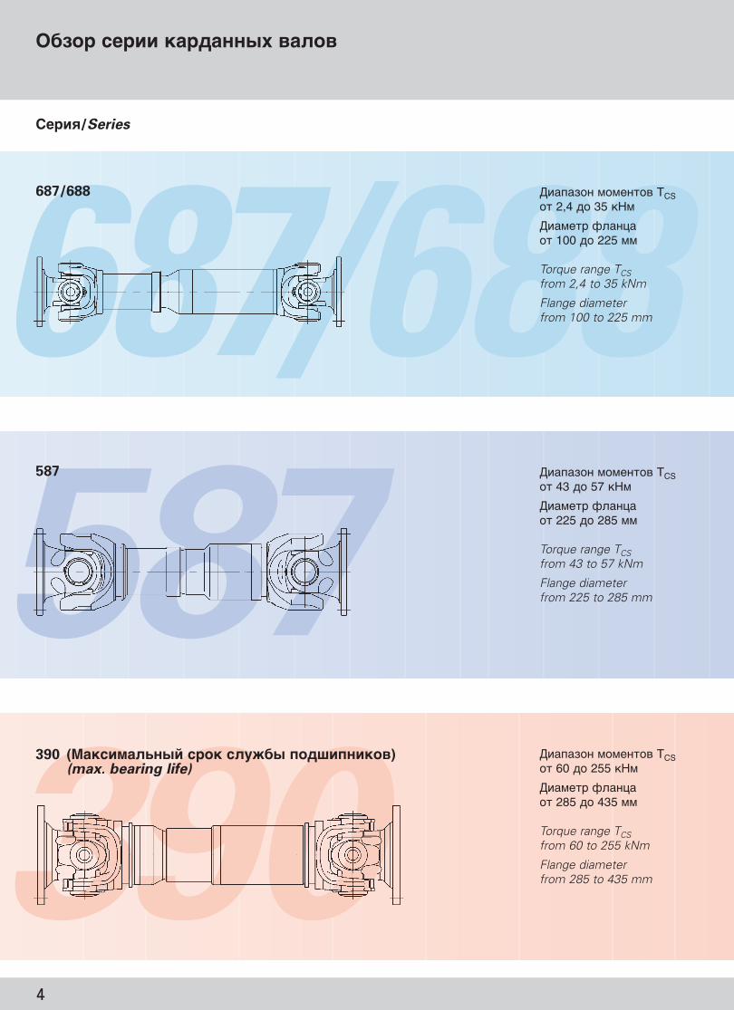
����� ����� ��������� ��
� ����� "�"���� TCS�� 2,4 �� 35 �&"
� �"�� (������� 100 �� 225 ""
Torque range TCSfrom 2,4 to 35 kNm
Flange diameterfrom 100 to 225 mm
� ����� "�"���� TCS�� 43 �� 57 �&"
� �"�� (������� 225 �� 285 ""
Torque range TCSfrom 43 to 57 kNm
Flange diameterfrom 225 to 285 mm
� ����� "�"���� TCS�� 60 �� 255 �&"
� �"�� (������� 285 �� 435 ""
Torque range TCSfrom 60 to 255 kNm
Flange diameterfrom 285 to 435 mm
�����/Series
687/688
587
390 (,���� ����� ���� ����� ����������)(max. bearing life)
GWB_Rus_prav.qxd 5/4/08 6:17 PM Page 6

5
Survey of cardan shaft series
����������� �����������/Design features #�����$�������� ��� ������/
Preferred application
! á‡Í˚Ú˚ÈÔÓ‰¯ËÔÌËÍÓ‚˚È ÛÁÂÎ
! äÓÏÔ‡ÍÚ̇fl ÍÓÌÒÚÛ͈Ëfl! å‡ÎÓÓ·ÒÎÛÊË‚‡ÂÏ˚È! òÎˈ˚, ÔÓÍ˚Ú˚Â
ÔÓÎËÏÂÓÏ! ꇷӘËÈ Û„ÓÎ ‰Ó 25°,
˜‡ÒÚ˘ÌÓ ‰Ó 44°
! Closed bearing eyes! Compact design! Low maintenance! Plastic-coated splines! Operating angle up to 25°,
partly up to 44°
! %��� "��-��� ���� ���!�� ������ ����� ������������
! B��+"��� ��� ��< � ���� �������� ���<�����< � ��
! D�"������ ��������� �! E� " � �������� ��� �����
��< � �! D�"������ �� ��, �������
�"������" ����"! B���� � ���� �� 15°
! Maximum bearing life in confined spaces
! Split bearing eyes with toothed bearing cap
! Compact design! Optimized roller bearing! Length compensation coated
with lubricating varnish! Operating angle up to 15°
! á‡Í˚Ú˚È ÔÓ‰¯ËÔÌËÍÓ‚˚ÈÛÁÂÎ
! äÓÏÔ‡ÍÚ̇fl ÍÓÌÒÚÛ͈Ëfl! å‡ÎÓÓ·ÒÎÛÊË‚‡ÂÏ˚È! òÎˈ˚, ÔÓÍ˚Ú˚ ÒχÁÓ˜Ì˚Ï
·ÍÓÏ (587.50 - ÔÓÎËÏÂÓÏ)! ꇷӘËÈ Û„ÓÎ ‰Ó 24°
! Closed bearing eyes! Compact design! Low maintenance! Splines coated with lubricating
varnish (587.50 – Plastic-coated)! Operating angle up to 24°
! èË‚Ó‰‡ ÎÓÍÓÏÓÚË‚Ó‚! ëÛ‰Ó‚˚ ÔË‚Ó‰‡! ä‡Ì˚! ÅÛχ„Ӊ·ÚÂθÌ˚Â
χ¯ËÌ˚! 凯ËÌÓÒÚÓÂÌËÂ
;�� ��� �����(�". )� ( ��� )
! Railway vehicles! Marine drives! Crane systems! Paper machines! General machinery
construction plants
Technical data (see Data sheets)
! èË‚Ó‰‡ ÎÓÍÓÏÓÚË‚Ó‚! èÓ͇ÚÌ˚ ÒÚ‡Ì˚! ëÛ‰Ó‚˚ ÔË‚Ó‰‡! 凯ËÌÓÒÚÓÂÌËÂ
;�� ��� �����(�". )� ( ��� )
! Railway vehicles! Rolling mill plants! Marine drives! General machinery construc-
tion plants
Technical data (see Data sheets)
! èË‚Ó‰‡ ÎÓÍÓÏÓÚË‚Ó‚! èÓ͇ÚÌ˚ ÒÚ‡Ì˚! ëÛ‰Ó‚˚ ÔË‚Ó‰‡! 凯ËÌÓÒÚÓÂÌËÂ
;�� ��� �����(�". )� ( ��� )
! Railway vehicles! Rolling mill plants! Marine drives! General machinery construc-
tion plants
Technical data (see Data sheets)
GWB_Rus_prav.qxd 5/4/08 6:17 PM Page 7

392/393 492
498 6
����� ����� ��������� ��
D����$ � "�"�� TCS�� 1880 �� 15000 �&"
� �"�� (������� 600 �� 1200 ""
*��-< ���"��������� � ������
Torque range TCSfrom 1880 to 15000 kNm
Flange diameter from 600 to 1200 mm
Larger sizes available on request
D����$ � "�"�� TCS�� 210 �� 1300 �&"
� �"�� (������� 285 �� 550 ""
Torque range TCSfrom 210 to 1300 kNm
Flange diameter from 285 to 550 mm
D����$ � "�"�� TCS�� 70 �� 1150 �&"
� �"�� (������� 225 �� 550 ""
Torque range TCSfrom 70 to 1150 kNm
Flange diameter from 225 to 550 mm
�����/Series
492 (,���� ����� ������� ��������� � ����)(max. torque capacity)
498
392/393 (&������ ������� ��������� � ���� /���� ���������� ���� ����� ����������)(high torque capacity/optimized bearing life)
GWB_Rus_prav.qxd 5/4/08 6:17 PM Page 8

7
Survey of cardan shaft series
����������� �����������/Design features #�����$�������� ��� ������/
Preferred application
GWB_Rus_prav.qxd 5/4/08 6:17 PM Page 9
! 3 �������� ����� � �� ������������� ������� ������ ��� ���������� ���� ������ ���������
! ��������� ���� ���������� ������ ���������������
! ����������� �������!����" #����
! ����� � � � 15°
! $��������� ������������� ������ ���������� � 393
! ��������� ���� ��������� � ������ ������ ���������
! ����������� �������!����" #����
! äÂÒÚÓ‚Ë̇ ËÁ ÍÓ‚‡ÌÌÓÈ ÒÚ‡ÎË! %�������� �����, �������
������� ����! ����� � � � 7° � 15°
! Increased torque capacity incomparison to 393
! Split bearing eyes with too-thed bearing cap
! Standard Hirth-serrated flange! Journal cross with low notch
factor! Length compensation coated
with lubricant varnish! Operating angle 7° up to 15°
! 3 operating angle versions formaximum torque or maximumbearing life capacity
! Split bearing eyes with toothed bearing cap
! Standard Hirth-serrated flange! Operating angle up to 15°
! &����� ������ ������� ������, ������� �� ��������������������� �������
! ��������� ���� ���������� ������ ���������������
! %�������� �������"��! äÂÒÚÓ‚Ë̇ ËÁ ÍÓ‚‡ÌÌÓÈ ÒÚ‡ÎË! %�������� �����, �������
������� ����! ����� � � � 10° � 15°! 393 − � ��������������
���� ������ ���������
! High torque capacity despitesmall connecting dimensions
! Split bearing eyes with toothed bearing cap
! Compact design! Journal cross with low notch
factor! Length compensation coated
with lubricating varnish! Operating angle 10° up to 15°! 393 with optimized bearing life
! '������ ������ �������� �����
! íflÊfiÎÓ χ¯ËÌÓÒÚÓÂÌËÂ
(��������� ������(��. ���"�!���"��)
! Main rolling mill drive units! Heavy-machinery construction
plants
Technical data (see Data sheets)
! +������� �����! +����� ��������! íflÊfiÎÓ χ¯ËÌÓÒÚÓÂÌËÂ
(��������� ������(��. ���"�!���"��)
! Rolling mill plants! Calender drives! Heavy-loaded plants of gene-
ral machinery construction
Technical data (see Data sheets)
! +������� �����! +����� ��������! íflÊfiÎÓ χ¯ËÌÓÒÚÓÂÌËÂ
(��������� ������(��. ���"�!���"��)
! Rolling mill plants! Calender drives! Extremely high loaded plants
of general machinery con-struction
Technical data (see Data sheets)

392/393587/190
8
���������� ������ ��������� �� � ������������� �����������
D����$ � "�"�� TCS�� 23 �� 94 �&"
� �"�� (������� 275 �� 405 ""
Torque range TCSfrom 23 to 94 kNm
Flange diameter from 275 to 405 mm
D����$ � "�"�� TCS�� 57 �� 1053 �&"
� �"�� (����� ��225/315 �� 550/710 ""
Torque range TCSfrom 57 to 1053 kNm
Flange diameter from225/315 to 550/710 mm
�����/Series
587/190 ������������ �����������/Super short designs
392/393 &�� � ������� ���������� /Tunnel joint shafts
#�� �����$��� ��/Intermediate shafts
GWB_Rus_prav.qxd 5/4/08 6:17 PM Page 10

9
Special designs of cardan shafts and additional equipment
����������� �����������/Design features #�����$�������� ��� ������/
Preferred application
GWB_Rus_prav.qxd 5/4/08 6:17 PM Page 11
! äÓÓÚ͇fl ÍÓÌÒÚÛ͈Ëfl Ò·Óθ¯ÓÈ ÍÓÏÔÂÌÒ‡ˆËÂȉÎËÌ˚
! äÓÏÔÂÌÒ‡ˆËfl ‰ÎËÌ˚ÔÓÒ‰ÒÚ‚ÓÏ ÚÛÌÌÂθÌÓ„Ó¯‡Ìˇ
! Ç˚ÒÓÍËÈ ÍÛÚfl˘ËÈ ÏÓÏÂÌÚÔË ÍÓÏÔ‡ÍÚÌ˚ı ‡Áχı¯‡Ìˇ
! ê‡Á˙fiÏÌ˚È ÛÁÂÎÔÓ‰¯ËÔÌË͇ Ò ÁÛ·˜‡Ú˚ÏÒÓ‰ËÌÂÌËÂÏ Í˚¯ÍË
! èÓ‰¯ËÔÌËÍË Ò Î‡·ËËÌÚÌ˚ÏÛÔÎÓÚÌÂÌËÂÏ
! ꇷӘËÈ Û„ÓÎ ‰Ó 10°/7,5°
! Shorter designs with largelength compensation
! Length compensation throughthe joint
! High torque capacity withsmall connection dimensions
! Split bearing eyes with too-thed bearing cap
! Bearings with labyrinth seals! Operating angle up to 10°/7,5°
! �������� �� ���� ����� (587)
! �������� �� ���� ����� (190)
! ëχÁ˚‚‡ÂÏ˚ ¯‡ÌË˚ Ë ¯Îˈ˚
! ������� ��� �� 5º
! Closed bearing eyes (587)! Split bearing eyes (190)! Joints and length compensati-
on regreasable! Operating angle up to 5°
! èË‚Ó‰‡ ÎÓÍÓÏÓÚË‚Ó‚! èÓ͇ÚÌ˚ ÒÚ‡Ì˚! ëÛ‰Ó‚˚ ÔË‚Ó‰‡! èË‚Ó‰˚ ͇·̉ӂ! ÅÛχ„Ӊ·ÚÂθÌ˚ χ¯ËÌ˚! 凯ËÌÓÒÚÓÂÌËÂ
����������� ������(��. � ����������)
! Railway vehicles! Rolling mill plants! Marine drives! Calender drives! Paper machines! General machinery
construction plants
Technical data (see Data sheets)
! !�������� ����� ! Rolling mill plants
! ë ÍÓÏÔÂÌÒ‡ˆËÂÈ ‰ÎËÌ˚ ËÎË ·ÂÁ! ë ‚˚ÌÓÒÌ˚Ï ÔÓ‰¯ËÔÌËÍÓÏ
! With or without length compensation
! Integrated bearing location
! !������ ������� ! Pump drives

0.01
0.01
0.03
9.019.029.03
0.04
0.04
0.02
9.04
9.06
GWB_Rus_prav.qxd 5/4/08 6:17 PM Page 12
10
ì͇Á‡ÌËfl ÔÓ ‡·ÓÚÂ Ò „‡·‡ËÚÌ˚ÏË ˜ÂÚÂʇÏËDirections for handling of data sheets
ëÎÂ‰Û˛˘Ë „‡·‡ËÚÌ˚˜ÂÚÂÊË ‰‡˛Ú ÔÓ‰Ó·ÌÓÂÔ‰ÒÚ‡‚ÎÂÌË ÓÒڇ̉‡ÚÌÓÈ ÔÓ„‡ÏÏÂÔÓÒÚ‡‚ÓÍ Ë ËÁ‰ÂÎËflxÒÔˆˇθÌÓ„Ó ËÒÔÓÎÌÂÌËfl,ËÁ„ÓÚ‡‚ÎË‚‡ÂÏ˚ı ÔÓ Á‡Í‡ÁÛ
��������������� ���
��������� � � � ����-������ ����, ���������� ���������
��������� � ��� � �-�������� ����,��������� � ���������
��������� � � � ����-������ ����, � � ����� ���������
��������� � ��� � �-�������� ����,� ��������� �� � �����������
�������������� ���
��������� � � � ����-������ ����, ���������� ���������
��������� � � � ����-������ ����, ����� � ����� ���������
����� ���������*
(� ���� �� � �������� � �� ����� ���� � ������� �)
�� ����� ���� � � � ���������� ����
�� ����� ���� � ��� � ��������� ����
������� �
* ������������ �/�� ������� � ���� ��
The following sheets givea summary of the currentstandard range of productsand some special designs.
Standard designs
Cardan shaft with lengthcompensation, tubulardesign
Cardan shaft without length compensation,tubular design
Cardan shaft with length compensation, shortdesign
Cardan shaft without length compensation, double flange shaft design
Special designs
Cardan shaft with largelength compensation,tubular design
Cardan shaft with length compensation, super shortdesign
Intermediate shafts*
(available with intermedia-te bearing on request)
Intermediate shaft withlength compensation
Intermediate shaft without length compensation
Midship shaft
* Data sheet and/or drawing on request

#�����!� � ���������� � ����<� �:Pictures provided by kind permission of:
ACHENBACH BUSCHHÜTTEN
Böhler Bleche GmbH
BOMBARDIER
BWG
Kranbau Köthen GmbH
MAN TAKRAF
Rolls-Royce Oy Ab
SCHOTTEL
SMS Demag
SMS Meer
VAI
Vossloh Schienenfahrzeugtechnik GmbH
11
#�� ��� ��� ������Application examples
GWB_Rus_prav.qxd 5/4/08 6:17 PM Page 13

12
#�� ��� ��� ������
GWB_Rus_prav.qxd 5/4/08 6:17 PM Page 14

13
Application examples
GWB_Rus_prav.qxd 5/4/08 6:17 PM Page 15
14
Lz
Lf
Lf
60° 45°
22,5°
∅H∅H
∅B
∅B
∅A
∅C
∅W ∅
S
∅K
Lz
F
G
M M
�
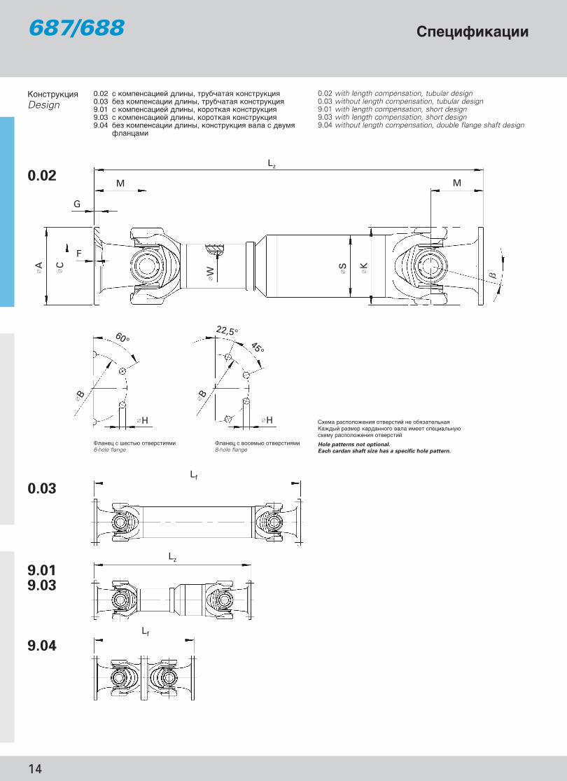
,���� � <��-� ������ �" ,���� � ���"-� ������ �" 6-hole flange 8-hole flange
)�"� ������!� � ������ � � �������-���D�!��� ���"� ���������� ���� "� �� ��-��� ��"� ������!� � ������ �
Hole patterns not optional.
Each cardan shaft size has a specific hole pattern.
D�������� �Design
0.02 � ��"���� � �� ��, ��������� ��������� �0.03 �� ��"���� �� ��, ��������� ��������� �9.01 � ��"���� � �� ��, �������� ��������� �9.03 � ��"���� � �� ��, �������� ��������� �9.04 �� ��"���� �� ��, ��������� � ���� � ���"�
(�����"
0.02 with length compensation, tubular design0.03 without length compensation, tubular design9.01 with length compensation, short design9.03 with length compensation, short design9.04 without length compensation, double flange shaft design
0.03
9.019.03
9.04
0.02
�����"������687/688
GWB_Rus_prav.qxd 5/4/08 6:17 PM Page 16

15
0.02
0.03
9.01
9.03
9.04
Lz min = " � "��-�� ���"�!��� �� ��La = ��"���� � �� ��Lf min = " � "��-��� ( �� �������� �� ��Lz + La = "��� "��-��� ������� �� ��G = �� ����GR = �� �� 1000 "" �����Jm = "�"�� ��� JmR = "�"�� ��� �� 1000 "" �����C = !������- � ����� �� �����CR = !������- � ����� �� 1000 "" �����
Lz min = shortest possible compressed lengthLa = Length compensationLf min = shortest fixed lengthLz + La = max. operating lengthG = Weight of shaftGR = Weight per 1000 mm tubeJm = Moment of inertiaJmR = Moment of inertia per 1000 mm tubeC = Torsional stiffness of shaft without tubeCR = Torsional stiffness per 1000 mm tube
.������� ��� ��� − &��� −,� ���� ������� − 0�������� ��� ���$����
Length dimensions · weights · moments of inertia · torsional stiffness
TCS = 1������������ ����� ��������� � ����*I�� ����� "�� ��� (���� ����-���� �����$�� "�"��� TCS���� ���-�����-�� ������-�, (������ ��� �� ���!�� ���- �� ���
TDW = )�������� ���������� �������� � ���*Lc = 3�4""������ �������� ����������** ()"��� � �� ( ��� ��������� �����)� = χÍÒËχθÌÓ ‰ÓÔÛÒÚËÏ˚È Û„ÓÎ ÓÚÍÎÓÌÂÌËfl ¯‡Ìˇ;������� ���� � � ������" ������ �������" ���� ��" "��"�-< � ����������� �����$ � "�"�� TDW1) J((�� ���� ���� �� ����� 2) D�� ����� ������ � (�����
TCS = Functional limit torque*If the permissible functional limit torque TCS is to be fully utilized, the flange connection must be reinforced.
TDW = Reversing fatigue torque*Lc = Bearing capacity factor** (see specifications of cardan shafts)� = max. deflection angle per jointTubular shafts with welded-on balancing plates have lower fatigue torques TDW1) Effective spigot depth2) Number of flange holes
)�� �� ��/Shaft size 687/688.15 687/688.20 687/688.25 687/688.30 687/688.35 687/688.40
TCS kNm 2,4 3,5 5 6,5 10 14
TDW kNm 0,7 1,0 1,6 1,9 2,9 4,4
Lc – 1,79 x 10⁻⁴ 5,39 x 10⁻⁴ 1,79 x 10⁻³ 2,59 x 10⁻³ 0,0128 0,0422
� <) ° 25 25 25 25 25 25 44 25 44A mm 100 120 120 120 150 150 180 150 150 180 180
K mm 90 98 113 127 127 144 144 160 160 160 160
B ± 0,1 mm mm 84 101,5 101,5 101,5 130 130 155,5 130 130 155,5 155,5C H7 mm 57 75 75 75 90 90 110 90 90 110 110F1) mm 2,5 2,5 2,5 2,5 3 3 3 3 3 3 3G mm 7 8 8 8 10 10 12 10 10 12 12H + 0,2 mm mm 8,25 10,25 10,25 10,25 12,25 12,1 14,1 12,1 12,1 14,1 14,1I2) – 6 8 8 8 8 8 8 8 8 8 8M mm 48 54 70 72 78 95 90 102 102 102 102S mm 63,5 x 2,4 76,2 x 2,4 89 x 2,4 90 x 3 90 x 3 100 x 3 100 x 3 120 x 3 100 x 4,5 120 x 3 100 x 4,5W DIN 5480 mm 36 x 1,5 40 x 1,5 45 x 1,5 48 x 1,5 48 x 1,5 54 x 1,5 54 x 1,5 62 x 1,75
D������� � �/Design B��"� ����/Shaft size 687/688.15 687/688.20 687/688.25 687/688.30 687/688.35 687/688.40
Lz min mm 346 379 458 492 504 582 572 586 693 586 693La mm 60 70 100 110 110 110 110 110 180 110 180G kg 5,7 8,4 12,0 13 14,2 24,0 25,6 28,7 30,3 29,4 30,9GR kg 3,62 4,37 5,13 6,44 6,44 7,18 7,18 8,66 10,6 8,66 10,6Jm kgm2 0,0043 0,0089 0,0144 0,0245 0,0245 0,043 0,0676 0,0706 0,0776 0,0806JmR kgm2 0,0034 0,0059 0,0096 0,0122 0,0122 0,0169 0,0169 0,0296 0,0242 0,0296 0,0242C Nm/rad. 0,26 x 10⁵ 0,42 x 10⁵ 0,71 x 10⁵ 0,78 x 10⁵ 0,78 x 10⁵ 1,18 x 10⁵ 2,17 x 10⁵ 1,61 x 10⁵ 2,17 x 10⁵ 1,61 x 10⁵
CR Nm/rad. 0,34 x 10⁵ 0,60 x 10⁵ 0,98 x 10⁵ 1,25 x 10⁵ 1,25 x 10⁵ 1,72 x 10⁵ 1,72 x 10⁵ 3,02 x 10⁵ 2,47 x 10⁵ 3,02 x 10⁵ 2,47 x 10⁵
Lf min mm 221 239 282 310 322 379 369 423 449 423 449G kg 4,1 5,8 8,6 8,6 9,8 18,0 19,6 22,8 21,0 23,4 21,6Jm kgm2 0,0038 0,0085 0,0129 0,0238 0,0238 0,04 0,066 0,0628 0,076 0,0728C Nm/rad. 0,44 x 10⁵ 0,86 x 10⁵ 1,44 x 10⁵ 1,74 x 10⁵ 1,74 x 10⁵ 1,81 x 10⁵ 3,35 x 10⁵ 2,78 x 10⁵ 3,35 x 10⁵ 2,78 x 10⁵
Lz min mm 296 322 361 379 391 510 500 505 525 505 525La min mm 38 41 36 36 36 70 70 70 60 70 60Lz max mm 348 381 425 453 465 550 540 545 645 545 645La max mm 90 100 100 110 110 110 110 110 180 110 180Lz min mm 245 274 313 331 343 419 409 441 – 441 –La min mm 25 27 28 29 29 45 45 45 – 45 –Lz max mm 280 317 355 397 409 484 474 506 – 506 –La max mm 60 70 70 95 95 110 110 110 – 110 –Lf min mm 192 216 240 288 312 380 360 408 408 408 408
Data sheets 687/688
GWB_Rus_prav.qxd 5/4/08 6:17 PM Page 17

16
Lz
Lf
Lf
45°
22,5° 36°
∅H ∅H
∅ B∅ B
�
∅A
∅C
∅W ∅S
∅K
Lz
F
G
M M
D�������� �Design
0.02 � ��"���� � �� ��, ��������� ��������� �0.03 �� ��"���� �� ��, ��������� ��������� �9.01 � ��"���� � �� ��, �������� ��������� �9.03 � ��"���� � �� ��, �������� ��������� �9.04 �� ��"���� �� ��, ��������� � ���� � ���"�
(�����"
0.02 with length compensation, tubular design0.03 without length compensation, tubular design9.01 with length compensation, short design9.03 with length compensation, short design9.04 without length compensation, double flange shaft design
0.03
9.019.03
9.04
0.02
�����"������687/688
,���� � ���"-� ������ �" ,���� � ����-� ������ �" 8-hole flange 10-hole flange
ëıÂχ ‡ÒÔÓÎÓÊÂÌËfl Ù·̈‚˚ı ÓÚ‚ÂÒÚËÈ ÏÂÌflÂÚÒfl ‚ Á‡‚ËÒËÏÓÒÚË ÓÚ ÚËÔÓ‡Áχ ͇‰‡ÌÌÓ„Ó ‚‡Î‡
Hole patterns not optional.
Each cardan shaft size has a specific hole pattern.
GWB_Rus_prav.qxd 5/4/08 6:17 PM Page 18

17
D������� � �/Design B��"� ����/Shaft size 687/688.45 687/688.55 687/688.65
Lz min mm 595 703 585 662 681 622 686 686La mm 110 180 110 110 110 110 110 110G kg 35,7 38,4 37,7 44,0 49,2 47,0 60,6 64,6GR kg 11,44 12,95 11,44 16,86 16,86 16,86 20,12 20,12Jm kgm2 0,1002 0,1242 0,1342 0,131 – 0,151 0,2224 0,2614JmR kgm2 0,0385 0,0357 0,0385 0,055 – 0,055 0,0932 0,0932C Nm/rad. 3,10 x 10⁵ 2,18 x 10⁵ 3,10 x 10⁵ 4,05 x 10⁵ – 4,05 x 10⁵ 5,63 x 10⁵ 5,63 x 10⁵
CR Nm/rad. 3,93 x 10⁵ 3,65 x 10⁵ 3,93 x 10⁵ 5,60 x 10⁵ 5,60 x 10⁵ 5,60 x 10⁵ 9,50 x 10⁵ 9,50 x 10⁵
Lf min mm 425 425 415 475 495 435 491 491G kg 28,0 27,8 30 33,1 – 36,1 47,3 51,3Jm kgm2 0,0954 0,0976 0,1294 0,1176 – 0,1376 0,2032 0,2422C Nm/rad. 4,82 x 10⁵ 3,71 x 10⁵ 4,82 x 10⁵ 5,39 x 10⁵ – 5,39 x 10⁵ 7,17 x 10⁵ 7,17 x 10⁵
Lz min mm 517 538 507 587 606 547 601 601La min mm 70 60 70 70 70 70 70 70Lz max mm 557 658 547 617 636 577 641 641La max mm 110 180 110 100 100 100 110 110Lz min mm 447 – 437 513 – 473 524 524La min mm 50 – 50 50 – 50 50 50Lz max mm 507 – 497 563 – 523 584 584La max mm 110 – 110 110 – 110 110 110Lf min mm 380 380 360 460 460 380 440 440
0.02
0.03
9.01
9.03
9.04
TCS = 1������������ ����� ��������� � ����*I�� ����� "�� ��� (���� ����-���� �����$�� "�"��� TCS���� ���-�����-�� ������-�, (������ ��� �� ���!�� ���- �� ���
TDW = )�������� ���������� �������� � ���*Lc = 3�4""������ �������� ����������** ()"��� � �� ( ��� ��������� �����)� = χÍÒËχθÌÓ ‰ÓÔÛÒÚËÏ˚È Û„ÓÎ ÓÚÍÎÓÌÂÌËfl ¯‡Ìˇ;������� ���� � � ������" ������ �������" ���� ��" "��"�-< � ����������� �����$ � "�"�� TDW1) J((�� ���� ���� �� ����� 2) D�� ����� ������ � (�����
TCS = Functional limit torque*If the permissible functional limit torque TCS is to be fully utilized, the flange connection must be reinforced.
TDW = Reversing fatigue torque*Lc = Bearing capacity factor** (see specifications of cardan shafts)� = max. deflection angle per jointTubular shafts with welded-on balancing plates have lower fatigue torques TDW1) Effective spigot depth2) Number of flange holes
Lz min = " � "��-�� ���"�!��� �� ��La = ��"���� � �� ��Lf min = " � "��-��� ( �� �������� �� ��Lz + La = "��� "��-��� ������� �� ��G = �� ����GR = �� �� 1000 "" �����Jm = "�"�� ��� JmR = "�"�� ��� �� 1000 "" �����C = !������- � ����� �� �����CR = !������- � ����� �� 1000 "" �����
Lz min = shortest possible compressed lengthLa = Length compensationLf min = shortest fixed lengthLz + La = max. operating lengthG = Weight of shaftGR = Weight per 1000 mm tubeJm = Moment of inertiaJmR = Moment of inertia per 1000 mm tubeC = Torsional stiffness of shaft without tubeCR = Torsional stiffness per 1000 mm tube
.������� ��� ��� - &��� -,� ���� ������� - 0�������� ��� ���$����
Length dimensions · weights · moments of inertia · torsional stiffness
Data sheets 687/688
)�� �� ��/Shaft size 687/688.45 687/688.55 687/688.65
TCS kNm 17 25 35
TDW kNm 5,1 7,3 11
Lc – 0,104 0,236 0,837
� <) ° 25 35 25 25 35 25 25 25A mm 180 180 225 180 180 225 180 225
K mm 174 174 174 178 178 178 204 204
B ± 0,1 mm mm 155,5 155,5 196 155,5 155,5 196 155,5 196C H7 mm 110 110 140 110 110 140 110 140F1) mm 3 3 5 3 3 5 3 5G mm 12 12 15 14 14 15 15 15H + 0,2 mm mm 14,1 14,1 16,1 16,1 16,1 16,1 16,1 16,1I2) – 8 8 8 10 10 8 10 8M mm 95 95 90 115 115 95 110 110S mm 120 x 4 110 x 5 120 x 4 120 x 6 120 x 6 120 x 6 142 x 6 142 x 6W DIN 5480 mm 68 x 1,75 78 x 2 88 x 2,5
GWB_Rus_prav.qxd 5/4/08 6:17 PM Page 19

18
48°
45°45°
38°22,5° 22,5°
∅H∅H
∅B∅ B ∅B s
∅H
s
Lz
Lf
Lf
�
∅A
∅C
∅W
∅S
∅K
Lz
F
G
MM
,���� � ���"-� ������ �" ,���� � ���"-� ������ �" 8-hole flange 8-hole flange
D�������� �Design
0.01 � ��"���� � �� ��, ��������� ��������� �0.02 � ���-<�� ��"���� � �� ��, ��������� ��������� �0.03 �� ��"���� �� ��, ��������� ��������� �9.01 � ��"���� � �� ��, �������� ��������� �9.02 � ��"���� � �� ��, �������� ��������� �9.03 � ��"���� � �� ��, �������� ��������� �9.04 �� ��"���� �� ��, ��������� � ���� � ���"� (�����"
0.01 with length compensation, tubular design0.02 with large length compensation, tubular design0.03 without length compensation, tubular design9.01 with length compensation, short design9.02 with length compensation, short design9.03 with length compensation, short design9.04 without length compensation, double flange shaft design
0.03
9.019.029.03
9.04
����������� "������ ���������� 6��"���� ���������� �� DIN 15451Standard flange connection Dowel pin connection according to DIN 15451
0.01587.55587.60
0.02587.50
�����"������587
GWB_Rus_prav.qxd 5/4/08 6:17 PM Page 20

19
D������� � �/Design B��"� ����/Shaft size 587.50 587.55 587.60
Lz min mm – – 840 840 870La mm – – 100 100 100G kg – – 118 123 132GR kg – – 29,1 29,1 38,2Jm kgm2 – – 0,657 0,737 0,950JmR kgm2 – – 0,190 0,190 0,239C Nm/rad. – – 8,7 x 10⁵ 8,7 x 10⁵ 9,6 x 10⁵
CR Nm/rad. – – 19,4 x 10⁵ 19,4 x 10⁵ 24,3 x 10⁵
Lz min mm 800 800 960 960 990La min mm 110 110 200 200 200G kg 86 91 155 160 170GR kg 23,7 23,7 29,1 29,1 38,2Jm kgm2 0,325 0,361JmR kgm2 0,111 0,111 0,190 0,190 0,239C Nm/rad. 5,29 x 10⁵ 5,29 x 10⁵
CR Nm/rad. 11,33 x 10⁵ 11,33 x 10⁵ 19,4 x 10⁵ 19,4 x 10⁵ 24,3 x 10⁵
Lf mm 540 540 610 610 640G kg 72 77 88 93 103GR kg 23,7 23,7 29,1 29,1 38,2Jm kgm2 0,270 0,306 0,547 0,627 0,84JmR kgm2 0,111 0,111 0,190 0,190 0,239C Nm/rad. 7,2 x 10⁵ 7,2 x 10⁵ 9,8 x 10⁵ 9,8 x 10⁵ 11,5 x 10⁵
CR Nm/rad. 11,33 x 10⁵ 11,33 x 10⁵ 19,4 x 10⁵ 19,4 x 10⁵ 24,3 x 10⁵
Lz min mm – – 815 815 843La mm – – 100 100 100G kg – – 110 115 142Jm kgm2 – – 0,64 0,72 0,93C Nm/rad. – – 8,8 x 10⁵ 8,8 x 10⁵ 9,7 x 10⁵
Lz mm – – 780 780 810La mm – – 65 65 70G kg – – 108 113 125Jm kgm2 – –C Nm/rad. – –Lz mm 550 600 650 696 550 600 650 696 720 720 750La mm 60 75 90 110 60 75 90 110 65 65 65G kg 61 66 68 70 66 71 73 75 113 118 126Lf mm 432 432 500 500 540G kg 58 68 81 91 110
)�� �� ��/Shaft size 587.50 587.55 587.60
TCS kNm 43 52 57
TDW kNm 13 18 23
Lc – 1,84 7,6 24,8
� <) ° 24 24 20 20 20 20A mm 225 250 250 285 285 285
K mm 215 215 250 250 265 265
B ± 0,1 mm mm 196 218 218 245 245 245Bs ± 0,1 mm mm – 214 214 – 240 –C H7 mm 140 140 140 175 175 175F1) mm 4,4 5,4 5,5 6,0 6,0 6,0G mm 15 18 18 20 20 20H + 0,2 mm mm 16,1 18,1 18,1 20,1 20,1 20,1Hs H12 mm – 25 25 – 28 –I2) – 8 8 8 8 8 8Is3) – – 4 4 – 4 –M mm 108 108 125 125 135 135S mm 144 x 7 144 x 7 168, 8 x 7,3 168,8 x 7,3 167,7 x 9,8 167,7 x 9,8W DIN 5480 mm 90 x 2,5 90 x 2,5 115 x 2,5 115 x 2,5 115 x 2,5 115 x 2,5
0.01
0.02*
0.03
9.01
9.02
9.03
9.04
Lz min = " � "��-�� ���"�!��� �� ��La = ��"���� � �� ��Lf min = " � "��-��� ( �� �������� �� ��Lz + La = "��� "��-��� ������� �� ��G = �� ����GR = �� �� 1000 "" �����Jm = "�"�� ��� JmR = "�"�� ��� �� 1000 "" �����C = !������- � ����� �� �����CR = !������- � ����� �� 1000 "" �����* *��-<�� ��"���� � �� �� � ������
Lz min = shortest possible compressed lengthLa = Length compensationLf min = shortest fixed lengthLz + La = max. operating lengthG = Weight of shaftGR = Weight per 1000 mm tubeJm = Moment of inertiaJmR = Moment of inertia per 1000 mm tubeC = Torsional stiffness of shaft without tubeCR = Torsional stiffness per 1000 mm tube* Larger length compensation on request
TCS = 1������������ ����� ��������� � ����*I�� ����� "�� ��� (���� ����-���� �����$�� "�"��� TCS���� ���-�����-�� ������-�, (������ ��� �� , ��� "��� <� (��" , ���!�� ���- �� ���.
�(��" ���$ � �����$ � "�"�� �� 30% ��< TCSTDW = )�������� ���������� �������� � ���*Lc = 3�4""������ �������� ����������** ()"��� � �� ( ��� ��������� �����)� = χÍÒËχθÌÓ ‰ÓÔÛÒÚËÏ˚È Û„ÓÎ ÓÚÍÎÓÌÂÌËfl ¯‡Ìˇ1) J((�� ���� ���� �� ����� 2) D�� ����� ������ � (����� (���������� (������ ��� �� )3) D�� ����� ������ � (����� (<� (���� ��� �� )
TCS = Functional limit torque*If the permissible functional limit torque TCSis to be fully utilized, the flange connection for example with dowel pins must be reinforced.
Yield torque 30% over TCSTDW = Reversing fatigue torque*Lc = Bearing capacity factor** (see specifications of cardan shafts)� = max. deflection angle per joint1) Effective spigot depth2) Number of flange holes (Standard flange connection)3) Number of flange holes (Dowel pin connection)
.������� ��� ��� - &��� -,� ���� ������� - 0�������� ��� ���$����
Length dimensions · weights · moments of inertia · torsional stiffness
Data sheets 587
GWB_Rus_prav.qxd 5/4/08 6:17 PM Page 21

20
48° 36°
36°36°38°18°18°
45°45°
22,5° 22,5°
∅H ∅H ∅H ∅H
∅B∅B
∅ B∅ B ∅Bs∅ B s
∅H
s
∅H
s
Lz
Lf
Lz
Lf
�
∅A
∅C
∅W
∅S
∅K
Lz
F
G
M M
D�������� �Design
0.01 � ��"���� � �� ��, ��������� ��������� �0.02 � ���-<�� ��"���� � �� ��, ��������� ��������� �0.03 �� ��"���� �� ��, ��������� ��������� �9.01 � ��"���� � �� ��, �������� ��������� �9.02 � ��"���� � �� ��, �������� ��������� �9.03 � ��"���� � �� ��, �������� ��������� �9.04 �� ��"���� �� ��, ��������� � ���� � ���"� (�����"
0.01 with length compensation, tubular design0.02 with large length compensation, tubular design0.03 without length compensation, tubular design9.01 with length compensation, short design9.02 with length compensation, short design9.03 with length compensation, short design9.04 without length compensation, double flange shaft design
����������� "������ ���������� 6��"���� ���������� �� DIN 15451Standard flange connection Dowel pin connection according to DIN 15451
,���� � ���"-� ������ �" ,���� � ����-� ������ �" 8-hole flange 10-hole flange
ëıÂχ ‡ÒÔÓÎÓÊÂÌËflÙ·̈‚˚ı ÓÚ‚ÂÒÚËÈÏÂÌflÂÚÒfl ‚ Á‡‚ËÒËÏÓÒÚË ÓÚ ÚËÔÓ‡Áχ ͇‰‡ÌÌÓ„Ó‚‡Î‡ (ÒÏ. Ú‡·ÎˈÛ). ÑÛ„Ó ÔÓ Á‡ÔÓÒÛ.
Each cardan shaft size
has a specific holepattern
(see table). Other hole
patterns on request.
,���� � ���"-� ������ �" ,���� � ����-� ������ �" 8-hole flange 10-hole flange
0.02
0.03
9.019.029.03
9.04
0.01
�����"������ ���� ����� ���� ����� ����������
390
GWB_Rus_prav.qxd 5/4/08 6:17 PM Page 22

21
)�� �� ��/Shaft size 390.60 390.65 390.70 390.75 390.80
TCS kNm 60 90 130 190 255
TDW kNm 23 36 53 75 102
Lc – 24,8 70,2 238 618 1563
� <) ° 15 15 15 15 15A mm 285 315 350 390 435
K mm 240 265 300 330 370
B ± 0,1 mm mm 245 280 310 345 385Bs ± 0,1 mm mm 240 270 300 340 378C H7 mm 175 175 220 250 280F1) mm 6 6 7 7 9G mm 20 22 25 28 32H + 0,2 mm mm 20,1 22,1 22,1 24,1 27,1Hs H12 mm 28 30 32 32 35I2) – 8 8 10 10 10Is3) – 4 4 4 4 4M mm 135 150 170 190 210S mm 167,7 x 9,8 218,2 x 8,7 219 x 13,3 273 x 11,6 273 x 19W DIN 5480 mm 115 x 2,5 150 x 3 150 x 3 185 x 5 185 x 5
.������� ��� ��� - &��� -,� ���� ������� - 0�������� ��� ���$����
Length dimensions · weights · moments of inertia · torsional stiffness
Data sheetsmax. bearing life
390
GWB_Rus_prav.qxd 5/4/08 6:17 PM Page 23
0.01
0.02*
0.03
9.01
9.02
9.03
9.04
Lz min = �������� ��������� ����La = ��������� ����Lf min = ��������� ���������� ����Lz + La = ���������� ������� ����G = ��� ����GR = ��� �� 1000 �� �����Jm = ������ ����JmR = ������ ���� �� 1000 �� �����C = �������� �� ����� ��� �����CR = �������� �� ����� �� 1000 �� �����* ������� ��������� ���� �� �������
Lz min = shortest possible compressed lengthLa = Length compensationLf min = shortest fixed lengthLz + La = max. operating lengthG = Weight of shaftGR = Weight per 1000 mm tubeJm = Moment of inertiaJmR = Moment of inertia per 1000 mm tubeC = Torsional stiffness of shaft without tubeCR = Torsional stiffness per 1000 mm tube* Larger length compensation on request
TCS = �� ��������� ����� �������� �������*��� ��������� ������ �����������!� ����"�!� ������� TCS����� ������������� ��������#, ��������� ��������, ��������� ������, ������ ���� ������.
$�������#"� ����"� ������ �� 30% ���� TCSTDW = ����������� ���������� ������� ������*Lc = ����������� ������ � �������� �** (&������ ������� �������' �����)� = χÍÒËχθÌÓ ‰ÓÔÛÒÚËÏ˚È Û„ÓÎ ÓÚÍÎÓÌÂÌËfl ¯‡Ìˇ1) *�������� !����� ����2) ��������� �������� ������ (����������� ��������� ��������)3) ��������� �������� ������ (�������� ��������)
TCS = Functional limit torque*If the permissible functional limit torque TCSis to be fully utilized, the flange connection for example with dowel pins must be reinforced.
Yield torque 30% over TCSTDW = Reversing fatigue torque*Lc = Bearing capacity factor** (see specifications of cardan shafts)� = max. deflection angle per joint1) Effective spigot depth2) Number of flange holes (Standard flange connection)3) Number of flange holes (Dowel pin connection)
���������/Design ����� ����/Shaft size 390.60 390.65 390.70 390.75 390.80
Lz min mm 870 980 1070 1210 1280La mm 100 135 135 170 170G kg 138 216 276 405 490GR kg 38,2 45,0 67,5 74,8 119Jm kgm2 1,04 1,61 2,51 4,20 8,20JmR kgm2 0,239 0,494 0,716 1,28 1,93C Nm/rad. 1,0 x 10⁶ 1,65 x 10⁶ 2,43 x 10⁶ 3,3 x 10⁶ 4,7 x 10⁶
CR Nm/rad. 2,43 x 10⁶ 5,04 x 10⁶ 7,3 x 10⁶ 1,3 x 10⁷ 1,96 x 10⁷
Lz min mm 990 1080 1170 1295 1365La min mm 200 220 220 250 250G kg 178 280 337 508 586GR kg 38,2 45,0 67,5 74,8 119Lf min mm 640 710 800 890 960G kg 109 159 218 302 385GR kg 38,2 45,0 67,5 74,8 119Lz mm 843 953 1043 1175 1245La mm 100 135 135 170 170G kg 136 213 273 402 482Lz mm 810 890 980 1100 1170La mm 70 75 75 95 95G kg 135 198 261 375 456Lz mm 750 835 925 1030 1100La mm 65 75 75 85 85G kg 135 202 264 371 453Lf mm 540 600 680 760 840G kg 108 146 210 284 380

22
30°
20°38° 15° 10°
45°
22,5°
∅H∅H∅H
∅ B ∅B∅ B
Lz
Lf
Lz
Lf
�
∅A X
∅C
∅W
∅S
∅K
Lz
F
Y
G
M M
D�������� �Design
0.01 � ��"���� � �� ��, ��������� ��������� �0.02 � ���-<�� ��"���� � �� ��, ��������� ��������� �0.03 �� ��"���� �� ��, ��������� ��������� �9.01 � ��"���� � �� ��, �������� ��������� �9.02 � ��"���� � �� ��, �������� ��������� �9.03 � ��"���� � �� ��, �������� ��������� �9.04 �� ��"���� �� ��, ��������� � ���� � ���"� (�����"
0.01 with length compensation, tubular design0.02 with large length compensation, tubular design0.03 without length compensation, tubular design9.01 with length compensation, short design9.02 with length compensation, short design9.03 with length compensation, short design9.04 without length compensation, double flange shaft design
0.02
0.03
9.019.029.03
9.04
,���� � ���"-� ������ �" ,���� � ����-� ������ �" ,���� � <��������-� ������ �"
8-hole flange 10-hole flange 16-hole flange
1������ ���������� ÔÓÒ‰ÒÚ‚ÓÏ ������� ������Flange connection with face key
ëıÂχ ‡ÒÔÓÎÓÊÂÌËfl Ù·̈‚˚ıÓÚ‚ÂÒÚËÈ ÏÂÌflÂÚÒfl ‚ Á‡‚ËÒËÏÓÒÚË ÓÚ ÚËÔÓ‡Áχ ͇‰‡ÌÌÓ„Ó ‚‡Î‡. (ÒÏ. Ú‡·ÎˈÛ). ÑÛ„Ó ÔÓ Á‡ÔÓÒÛ.
Each cardan shaft size has a specific
holepattern (see table).
Other hole patterns on request.
0.01
�����"������������ ������� ��������� � ����
392/393
GWB_Rus_prav.qxd 5/4/08 6:17 PM Page 24

23
D������� � �/Design B��"� ����/Shaft size 392.50 392.55 392.60 392.65 392.70 393.75 393.80 393.85 393.90
Lz min mm 890 1010 1090 1240 1310 1430 1620 1820 2035La mm 100 135 135 170 170 170 170 190 210G kg 129 214 272 406 493 732 1055 1468 2209GR kg 38,2 45 67,5 74,8 119 210,4 255,6 311,3 401,1Jm kgm2 1,02 1,43 2,23 3,80 6,5 11,72 17,84 25,21 40,76JmR kgm2 0,239 0,494 0,716 1,28 1,93 3,02 5,38 7,87 13,3C Nm/rad. 9,5 x 10⁵ 1,42 x 10⁶ 2,36 x 10⁶ 3,1 x 10⁶ 4,4 x 10⁶ 5,19 x 10⁶ 7,86 x 10⁶ 9,44 x 10⁶ 1,43 x 10⁷
CR Nm/rad. 2,43 x 10⁶ 5,06 x 10⁶ 7,3 x 10⁶ 1,3 x 10⁷ 1,96 x 10⁷ 3,08 x 10⁷ 5,48 x 10⁷ 8,03 x 10⁷ 1,36 x 10⁸
Lz min mm 1010 1110 1190 1325 1395 1570 1780 1975 2190La min mm 200 220 220 250 250 310 330 345 365G kg 171 275 331 515 603 796 1158 1589 2367GR kg 38,2 45 67,5 74,8 119 210,4 255,6 311,3 401,1Lf min mm 660 740 820 920 990 977 1110 1240 1380G kg 101 156 215 301 389 538 748 1052 1600GR kg 38,2 45 67,5 74,8 119 210,4 255,6 311,3 401,1Lz mm 863 983 1063 1205 1275 1363 1550 1750 1955La mm 100 135 135 170 170 170 170 190 210G kg 130 210 269 402 487 718 1037 1446 2177Lz mm 830 920 1000 1130 1200 1300 1400 1630 1770La mm 70 75 75 95 95 90 90 100 100G kg 124 204 263 375 466 641 876 1171 1717Lz mm 770 865 945 1060 1130 1200 1300 1520 1680La mm 65 75 75 85 85 70 70 80 80G kg 123 197 260 371 457 602 832 1116 1657Lf mm 580 660 720 820 900 820 940 1060 1160G kg 94 145 207 288 391 485 653 922 1443
)�� �� ��/Shaft size 392.50 392.55 392.60 392.65 392.70 393.75 393.80 393.85 393.90
TCS kNm 70 105 150 215 295 390 580 750 1150
TDW kNm 23 36 53 75 102 140 220 285 435
Lc – 7,6 25,2 82,6 261 684 1700 7070 15600 62600
� <) ° 15 15 15 15 15 10 10 10 10A mm 225 250 285 315 350 390 435 480 550
K mm 225 250 285 315 350 390 435 480 550
B mm 196 218 245 280 310 345 385 425 492C H7 mm 105 105 125 130 155 170 190 205 250F1) mm 4,5 5 6 7 7 8 10 12 12G mm 20 25 27 32 35 40 42 47 50H mm 17 19 21 23 23 25 28 31 31I2) – 8 8 8 10 10 10 16 16 16M mm 145 165 180 205 225 205 235 265 290S mm 167,7 x 9,8 218,2 x 8,7 219 x 13,3 273 x 11,6 273 x 19 273 x 36 323,9 x 36 355,6 x 40 406,4 x 45X e9 mm 32 40 40 40 50 70 80 90 100Y mm 9 12,5 15 15 16 18 20 22,5 22,5W DIN 5480 mm 115 x 2,5 150 x 3 150 x 3 185 x 5 185 x 5 185 x 5 210 x 5 210 x 5 240 x 5
0.01
0.02*
0.03
9.01
9.02
9.03
9.04
TCS = 1������������ ����� ��������� � ����*�(��" ���$ � �����$ � "�"�� �� 30% ��< TCSTDW = )�������� ���������� �������� � ���*Lc = 3�4""������ �������� ����������** ()"��� � �� ( ��� ��������� �����)� = χÍÒËχθÌÓ ‰ÓÔÛÒÚËÏ˚È Û„ÓÎ ÓÚÍÎÓÌÂÌËfl ¯‡Ìˇ1) J((�� ���� ���� �� ����� 2) D�� ����� ������ � (�����
TCS = Functional limit torque*Yield torque 30% over TCSTDW = Reversing fatigue torque*Lc = Bearing capacity factor** (see specifications of cardan shafts)� = max. deflection angle per joint1) Effective spigot depth2) Number of flange holes
Lz min = " � "��-�� ���"�!��� �� ��La = ��"���� � �� ��Lf min = " � "��-��� ( �� �������� �� ��Lz + La = "��� "��-��� ������� �� ��G = �� ����GR = �� �� 1000 "" �����Jm = "�"�� ��� JmR = "�"�� ��� �� 1000 "" �����C = !������- � ����� �� �����CR = !������- � ����� �� 1000 "" �����* *��-<�� ��"���� � �� �� � ������
Lz min = shortest possible compressed lengthLa = Length compensationLf min = shortest fixed lengthLz + La = max. operating lengthG = Weight of shaftGR = Weight per 1000 mm tubeJm = Moment of inertiaJmR = Moment of inertia per 1000 mm tubeC = Torsional stiffness of shaft without tubeCR = Torsional stiffness per 1000 mm tube* Larger length compensation on request
.������� ��� ��� - &��� -,� ���� ������� - 0�������� ��� ���$����
Length dimensions · weights · moments of inertia · torsional stiffness
Data sheetshigh torque capacity
392/393
GWB_Rus_prav.qxd 5/4/08 6:17 PM Page 25

24
Lz
Lf
Lf
30° 22,5°
∅H∅H
∅B∅ B
D�������� �Design
0.01 � ��"���� � �� ��, ��������� ��������� �0.03 �� ��"���� �� ��, ��������� ��������� �9.01 � ��"���� � �� ��, �������� ��������� �9.02 � ��"���� � �� ��, �������� ��������� �9.03 � ��"���� � �� ��, �������� ��������� �9.04 �� ��"���� �� ��, ��������� � ���� � ���"� (�����"
0.01 with length compensation, tubular design0.03 without length compensation, tubular design9.01 with length compensation, short design9.02 with length compensation, short design9.03 with length compensation, short design9.04 without length compensation, double flange shaft design
,���� � ��������-� ������ �" ,���� � <��������-� ������ �" 12-hole flange 16-hole flange
1������ ���������� ��� �� ��� ���$����� ���������� ;����Flange connection with Hirth-serration
ëıÂχ ‡ÒÔÓÎÓÊÂÌËfl Ù·̈‚˚ıÓÚ‚ÂÒÚËÈ ÏÂÌflÂÚÒfl ‚ Á‡‚ËÒËÏÓÒÚË ÓÚ ÚËÔÓ‡Áχ ͇‰‡ÌÌÓ„Ó ‚‡Î‡. (ÒÏ. Ú‡·ÎˈÛ). ÑÛ„Ó ÔÓ Á‡ÔÓÒÛ.
Each cardan shaft size has a specific
holepattern (see table).
Other hole patterns on request.
0.03
9.04
9.019.029.03
0.01
492 �����"������ ���� ����� ������� ��������� � ����
�
∅A
∅W
∅S
∅K
Lz
G
M M
GWB_Rus_prav.qxd 5/4/08 6:17 PM Page 26

25
.������� ��� ��� (Lz/La) �����������0.02 · 9.02 · 9.03 �� �������
Length dimensions (Lz/La) of the designs 0.02 · 9.02 · 9.03 on request
Lz min = " � "��-�� ���"�!��� �� ��La = ��"���� � �� ��Lf min = " � "��-��� ( �� �������� �� ��Lz + La = "��� "��-��� ������� �� ��G = �� ����GR = �� �� 1000 "" �����Jm = "�"�� ��� JmR = "�"�� ��� �� 1000 "" �����C = !������- � ����� �� �����CR = !������- � ����� �� 1000 "" �����
Lz min = shortest possible compressed lengthLa = Length compensationLf min = shortest fixed lengthLz + La = max. operating lengthG = Weight of shaftGR = Weight per 1000 mm tubeJm = Moment of inertiaJmR = Moment of inertia per 1000 mm tubeC = Torsional stiffness of shaft without tubeCR = Torsional stiffness per 1000 mm tube
492Data sheetsmax. torque capacity
.������� ��� ��� - &��� -,� ���� ������� - 0�������� ��� ���$����
Length dimensions · weights · moments of inertia · torsional stiffness
TCS = 1������������ ����� ��������� � ����*�(��" ���$ � �����$ � "�"�� �� 30% ��< TCSTDW = )�������� ���������� �������� � ���*Lc = 3�4""������ �������� ����������** ()"��� � �� ( ��� ��������� �����)� = χÍÒËχθÌÓ ‰ÓÔÛÒÚËÏ˚È Û„ÓÎ ÓÚÍÎÓÌÂÌËfl ¯‡Ìˇ1) D�� ����� ������ � (�����
TCS = Functional limit torque*Yield torque 30% over TCSTDW = Reversing fatigue torque*Lc = Bearing capacity factor** (see specifications of cardan shafts)� = max. deflection angle per joint1) Number of flange holes
)�� �� ��/Shaft size 492.60 492.65 492.70 492.75 492.80 492.85 492.90
TCS kNm 210 245 340 440 410 650 580 850 770 1300 1170
TDW kNm 100 115 160 210 190 280 250 400 360 600 540
Lc – 93 332 860 2060 7390 17400 61200
� <) ° 7 7 7 10 15 10 15 10 15 10 15A mm 285 315 350 390 435 480 550K mm 285 315 350 390 435 480 550B mm 255 280 315 350 395 445 510G mm 35 35 40 45 50 55 65H mm 15 17 17 19 19 21 23I1) – 10 10 12 12 16 16 16M mm 200 220 240 260 280 300 330S mm 244,5 x 22,2 244,5 x 28 273 x 30 323,9 x 36 355,6 x 40 406,4 x 40 457 x 50W DIN 5480 mm 185 x 5 185 x 5 210 x 5 210 x 5 210 x 5 240 x 5 290 x 8
D������� � �/Design B��"� ����/Shaft size 492.60 492.65 492.70 492.75 492.80 492.85 492.90
Lz min mm 1440 1520 1680 1750 1900 2130 2415La mm 135 135 150 170 170 190 210G kg 472 568 788 1025 1355 1873 2750GR kg 121 149 180 255,6 311,3 361,4 501,94Jm kgm2 4,16 5,16 7,73 15 30,7 50,4 92,7JmR kgm2 1,52 1,78 2,69 5,38 7,88 12,28 21,1C Nm/rad. 3,32 x 10⁶ 4,31 x 10⁶ 5,97 x 10⁶ 6,76 x 10⁶ 9,7 x 10⁶ 13,64 x 10⁶ 19,44 x 10⁶
CR Nm/rad. 1,55 x 10⁷ 1,82 x 10⁷ 2,75 x 10⁷ 5,48 x 10⁷ 8,03 x 10⁷ 12,51 x 10⁷ 21,5 x 10⁷
Lf min mm 940 1020 1130 1220 1320 1450 1620G kg 311 407 557 819 1040 1330 1880GR kg 121 149 180 198,9 311,3 361,4 501,9Lz mm 1380 1460 1620 1700 1840 2050 2340La mm 135 135 150 170 170 190 210G kg 465 559 777 1010 1340 1850 2710Lf mm 800 880 980 1040 1120 1200 1320G kg 286 374 514 780 1000 1300 1830
0.01
0.03
9.01
9.04
GWB_Rus_prav.qxd 5/4/08 6:17 PM Page 27

26
Lf
Lf
18° 15°
∅H∅H
∅ B ∅ B
�
∅A
∅K
Lz
G
M M MM
D�������� �Design
0.01 � ��"���� � �� ��, ��������� ��������� �0.03 �� ��"���� �� ��, ��������� ��������� �9.04 �� ��"���� �� ��, ��������� � ���� � ���"� (�����"
0.01 with length compensation, tubular design0.03 without length compensation, tubular design9.04 without length compensation, double flange shaft design
0.03
9.04
,���� � �������-� ������ �" ,���� � �������-� ����-"� ������ �" 20-hole flange 24-hole flange
1������ ���������� ��� �� ��� ���$����� ���������� ;����Flange connection with Hirth-serration
ëıÂχ ‡ÒÔÓÎÓÊÂÌËfl Ù·̈‚˚ıÓÚ‚ÂÒÚËÈ ÏÂÌflÂÚÒfl ‚ Á‡‚ËÒËÏÓÒÚË ÓÚ ÚËÔÓ‡Áχ ͇‰‡ÌÌÓ„Ó ‚‡Î‡. (ÒÏ. Ú‡·ÎˈÛ). ÑÛ„Ó ÔÓ Á‡ÔÓÒÛ.
Each cardan shaft size has a specific
holepattern (see table).
Other hole patterns on request.
0.01
�����"������498
GWB_Rus_prav.qxd 5/4/08 6:18 PM Page 28
27
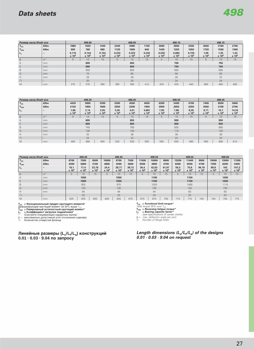
)�� �� ��/Shaft size 498.40 498.45 498.50 498.55 498.60
TCS kNm 8700 7500 6500 10000 8700 7500 11500 10000 8600 13200 11400 9900 15000 13000 11200
TDW kNm 4200 3600 3100 4800 4200 3600 5500 4800 4100 6300 5500 4700 7200 6200 5400
Lc – 16,1 17,4 23,78 24,4 28,71 38,73 36,4 42,63 61,67 56,3 70,8 96,19 89,9 102 147,2
x 106 x 106 x 106 x 106 x 106 x 106 x 106 x 106 x 106 x 106 x 106 x 106 x 106 x 106 x 106
� <) ° 5 10 15 5 10 15 5 10 15 5 10 15 5 10 15A mm 1000 1050 1100 1150 1200
K mm 1000 1050 1100 1150 1200
B mm 925 975 1025 1065 1115G mm 125 130 135 140 150H mm 44 44 44 50 50I1) – 20 20 20 20 20M mm 625 625 655 645 645 675 670 670 700 715 715 745 740 740 775
)�� �� ��/Shaft size 498.20 498.25 498.30 498.35
TCS kNm 4420 3800 3300 5300 4500 4050 6300 5400 4700 7400 6500 5600
TDW kNm 2120 1850 1600 2550 2200 1950 3050 2650 2250 3500 3100 2700
Lc – 1,69 2,14 2,55 3,26 4,01 4,681 7,05 7,86 8,29 9,71 10,7 14,24
x 106 x 106 x 106 x 106 x 106 x 106 x 106 x 106 x 106 x 106 x 106 x 106
� <) ° 5 10 15 5 10 15 5 10 15 5 10 15A mm 800 850 900 950
K mm 800 850 900 950
B mm 745 785 835 885G mm 100 105 110 120H mm 32 38 38 38I1) – 24 24 24 24M mm 480 480 500 530 530 555 555 555 580 580 580 610
)�� �� ��/Shaft size 498.00 498.05 498.10 498.15
TCS kNm 1880 1620 1430 2340 2080 1750 3000 2600 2200 3640 3100 2700
TDW kNm 900 780 680 1120 1000 840 1430 1250 1050 1750 1500 1300
Lc – 0,115 0,144 0,154 0,224 0,322 0,343 0,530 0,684 0,720 1,09 1,35 1,43
x 106 x 106 x 106 x 106 x 106 x 106 x 106 x 106 x 106 x 106 x 106 x 106
� <) ° 5 10 15 5 10 15 5 10 15 5 10 15A mm 600 650 700 750
K mm 600 650 700 750
B mm 555 605 655 695G mm 75 80 90 95H mm 26 26 26 32I1) – 20 20 24 24M mm 370 370 390 390 390 410 420 420 440 460 460 480
.������� ��� ��� (Lz/Lf/La) �����������0.01 · 0.03 · 9.04 �� �������
Length dimensions (Lz/Lf/La) of the designs 0.01 · 0.03 · 9.04 on request
TCS = 1������������ ����� ��������� � ����*�(��" ���$ � �����$ � "�"�� �� 30% ��< TCSTDW = )�������� ���������� �������� � ���*Lc = 3�4""������ �������� ����������** ()"��� � �� ( ��� ��������� �����)� = χÍÒËχθÌÓ ‰ÓÔÛÒÚËÏ˚È Û„ÓÎ ÓÚÍÎÓÌÂÌËfl ¯‡Ìˇ1) D�� ����� ������ � (�����
TCS = Functional limit torque*Yield torque 30% over TCSTDW = Reversing fatigue torque*Lc = Bearing capacity factor** (see specifications of cardan shafts)� = max. deflection angle per joint1) Number of flange holes
Data sheets 498
GWB_Rus_prav.qxd 5/4/08 6:18 PM Page 29

28
∅A
∅C
∅W
∅K
Lz
F
G
M M
�
∅A
∅C
∅W
∅K
Lz
F
G
M M
�
36°
36°
∅H
∅ B
36°
36°
∅H
GWB_Rus_prav.qxd 5/4/08 6:18 PM Page 30
∅ B
9.06 ��������� � � � ���������� ����,����� � ���� � ���������
9.06 Cardan shaft with length compensation, super short design
� ���������Design
9.06
9.06 �����/Series 190
�����/Series 587
����� � ������� ���������10-hole flange
����� � ������� ���������10-hole flange
�������������� ������ ���������
587/190

29
D������� � �/Design B��"� ����/Shaft size 587.50 190.55 190.60 190.65 190.70
Lz mm 415 495 545 600 688La mm 40 40 40 40 55G kg 60 98 120 169 256Jm kgm2 0,33 0,624 1,179 2,286 3,785
)�� �� ��/Shaft size 587.50 190.55 190.60 190.65 190.70
TCS kNm 23 33 48 68 94
TDW kNm 8,5 11 21 25 36
Lc – 1,84 7,0 58,5 166 510
� <) ° 5 5 5 5 5A mm 275 305 348 360 405
K mm 215 250 285 315 350
B ± 0,1 mm mm 248 275 314 328 370C H7 mm 140 140 175 175 220F1) mm 4,5 5,5 6,5 6 6,5G mm 15 15 18 18 22H + 0,2 mm mm 14,1 16,1 18,1 18,1 20,1I2) – 10 10 10 10 10M mm 68 80 90 100 108W DIN 5482/5480 mm 90 x 2,5 100 x 94 100 x 94 130 x 3 150 x 3
9.06
TCS = 1������������ ����� ��������� � ����*�(��" ���$ � �����$ � "�"�� �� 30% ��< TCSTDW = )�������� ���������� �������� � ���*Lc = 3�4""������ �������� ����������** ()"��� � �� ( ��� ��������� �����)� = χÍÒËχθÌÓ ‰ÓÔÛÒÚËÏ˚È Û„ÓÎ ÓÚÍÎÓÌÂÌËfl ¯‡Ìˇ1) J((�� ���� ���� �� ����� 2) D�� ����� ������ � (�����
TCS = Functional limit torque*Yield torque 30% over TCSTDW = Reversing fatigue torque*Lc = Bearing capacity factor** (see specifications of cardan shafts)� = max. deflection angle per joint1) Effective spigot depth2) Number of flange holes
Lz = " � "��-�� ���"�!��� �� ��La = ��"���� � �� ��Lz + La = "��� "��-��� ������� �� ��G = �� ����Jm = "�"�� ���
Lz = shortest compressed lengthLa = Length compensationLz + La = max. operating lengthG = Weight of shaftJm = Moment of inertia
.������� ��� ��� - &��� -,� ���� �������
Length dimensions · weights · moments of inertia
Data sheetsSuper short designs
587/190
GWB_Rus_prav.qxd 5/4/08 6:18 PM Page 31

30
<��������*� ��� �"�������"������
∅A
F
K
L
D
G
SW
Fk
∅C
k
∅B
∅C
B��"� "�(��/Coupling size 330.10 330.20 330.30 330.40 330.50 330.55
687/688.15 687/688.25 687/688.30 687/688.40 687/688.55)�� �� ����/Shaft connection 687/688.20 687/688.45 587.50 392.50 587.55 392.55
287.10 687/688.35 687/688.40 687/688.45 687/688.65%���-/Model Nr. 000 003 003 003 000 001 000 001
A mm 100 130 150 180 225 225 250 250B mm 84 101,5 130 155,5 196 196 218 218C1) mm 57 75 90 110 140 105 140 105Ck
11) mm 57 75 90 110 140 105 140 105D2) mm 20 38 40 40 45 45 45 45F mm 2,5 2,5 3,5 4 5 5 6 6Fk mm 2,3–0,2 2,3–0,15 2,3–0,2 2,3–0,15 4–0,2 4–0,2 5–0,2 5–0,2
G mm 76 100 100 112 144 144 148 162I3) – 6 8 8 8 8 8 8 8K4) – M 8 x 18 M 10 x 22 M 12 x 25 M 14 x 28 M 16 x 35 M 16 x 40 M 18 x 40 M 18 x 45L10) mm 10 11 14 20 18 18 21 21Gk
12) kg 4,7 7,5 10,6 16,4 34 36 40 49'����/Nut Nm 35 69 120 190 295 295 405 405D�����-/Extension 5) Nr. 2365/13 M 2365/17 M 2365/19 M 22 M 24 R 24 R 27 R 27 RL ���-/Spindle Nm 30 45 80 100 190 190 220 220;������� ����/Socket wrench 6) Nr. 1/2“ D 19 SW 13 1/2“ D 19 SW 17 1/2“ D 19 SW 22
D�������� � �� � ���-��" �������" ��� �� " ��� ���-< � ��������Design with spiral serration for higher speeds
���������� �� 4������������������ � ���������� �"��
)��� ������ �� ���� ��� ��������" < ���� � ��-���, ������!���� �� �������� ���� "�(��. L ���- "�!����- ������ � ���� ������ ���-����� ��� ���� �. L ���-����� ����� ��������" ��������� ��˛�� (�"��� � ���� ��).
&�� ����
1. ��� ���� " "�(�� ��� ��-, ��� ���-� "�(�� �������−��� ��� �-��.
2. &������ ������ � �"��� ������" . L ���- ���!� ���- ������� � �� � ������� �����, � �� ��� � �������.
3. )�� �� � ��"�����" "�(�� ���� ����� � ������ .��������� ��������� ����������!
� ����� ����˛$� �� ?� " �������� ���������+"��� "�(�� ��������� ��� ���!� ���- ����������� �����. L ��� � ��-��� �"����� �����$ ��" MoS2. %� ���"���" ��"� �� ��"� �� ���� �- �������˛ �"����.
Operating instructions
Engaging and disengaging the coupling
The engaging and disengaging is done by operating the threadedspindle located in the inner part of the coupling. The spindle can bereached from two sides and be operated. The spindle is tightened bymeans of a socket wrench (see table).
Attention:
1. Before engaging the coupling make sure that the coupling teeth areproperly fitted.
2. The engagement direction is marked by arrows. The spindle may betightened either clockwise or anti-clockwise.
3. The joint with the coupling component falls back when disengaged.Danger of injury!
In case of a subsequent installation of the quick release coupling thecardan shaft must be correspondingly shorter. The threaded spindlesof the coupling are lubricated by the supplier with MoS2. We recom-mend relubricating from time to time.
)�� �� 287/587 )�� �� 392687/688 ÔÓÒ‰ÒÚ‚ÓÏ ������� <���
Connection 287/587 Connection 392687/688 with face key
��� ������� � ������ � �". �� ( ��� ����������˛$ ���������� �����
For hole distribution see data sheetsof the corresponding cardan shaft
330
GWB_Rus_prav.qxd 5/4/08 6:18 PM Page 32

31
∅A
F
K
L
D
G
SW
Fk
∅C
k∅B
∅C
B��"� "�(��/Coupling size 230.60 230.65 230.70 230.75 230.80
)�� �� ����/Shaft connection 390.60 392.60 390.65 392.65 390.70 392.70 390.75 393.75 390.80 393.80%���-/Model Nr. 000 001 000 001 000 001 000 001 000 001
A mm 285 285 315 315 350 350 390 390 435 435B mm 245 245 280 280 310 310 345 345 385 385C1) mm 175 125 175 130 220 155 250 170 280 190Ck
11) mm 175 125 175 130 220 155 250 170 280 190D2) mm 64 64 66 66 72 72 82 82 92 92F mm 7 7 7 8 8 8 8 8 10 10Fk mm 6–0,2 6–0,5 6–0,2 7–0,5 7–0,3 7–0,5 7–0,2 7–0,5 9–0,5 9–0,5
G mm 160 174 172 192 184 204 196 220 226 246I3) – 8 8 8 10 10 10 10 10 10 16K4) – M 20 x 55 M 20 x 55 M 22 x 50 M 22 x 60 M 22 x 50 M 22 x 60 M 24 x 55 M 24 x 70 M 27 x 65 M 27 x 75L10) mm 23 23 25 25 25 25 27 27 30 30Gk
12) kg 66 71 83 95 110 120 143 150 210 230'����/Nut Nm 580 580 780 780 780 780 1000 1000 1500 1500B��< � ��-/Extension 5) Nr. 30 R 30 R 32 R 32 R 32 R 32 R 36 R 36 R 41 R 41 RL ���-/Spindle Nm 290 290 400 400 550 550 680 680 9509) 9509);������� ����/Socket wrench 6) Nr. 3/4“ D 32 SW 22 3/4“ D 32 SW 27 3/4“ D 32 SW 27 3/4“ D 32 SW 32 3/4“ D 32 SW 36X = 4 D���/spanners 8) Nr. TD 750
èË ÒÍÓÓÒÚË ‚˚¯Â 1000 ��/" �,�!�������, ���! ��- � ��< " �!���" .
���� ��������� � ������.
For applications with speedshigher than 1000 rpm pleasecontact our engineers.Other designs on request.
230Data sheetsQuick release couplings
��� �������� ����7) � ����� �����$ � "�"����Torque wrench7) Torque range
; /Type ��/from ��/to756 B 20 Nm 100 Nm756 C 80 Nm 300 Nm756 D 280 Nm 760 Nm
GWB_Rus_prav.qxd 5/4/08 6:18 PM Page 33
! �������" � �������������� ��#���� � ��������� ��" �� � ��� � 1000 #/���.
Design with trapezoidal serration for speeds up to 1000 rpm
� �������� 390 � �������� 392/393��� � � $� ���� � �� ���
Connection 390 Connection 392/393with face key
%�" ������������" ������ ��. ������������ ������$�& ��������&��� �
For hole distribution see data sheets of the corresponding cardan shaft
1. Spigot fit H72. Disengaging movement for
separation of the coupling3. Number of stud bolts per flange4. Dimensions of the bolt connections
Stud bolt DIN 938Self locking hexagon nut DIN 980
5. Jaw or ring extension in accordance with GWB standard N 4.2.5
6. Gedore socket spanner set for tightening the spindle
7. Rahsol torquemeter8. Force multiplier spanner
x = 4 (TD 750)9. Adjusting moment of the torque
wrench 756 C = 238 Nm10. Thread depth11. Fit h6 up to series 390
Fit f8 for series 392/39312. Gk = Weight of couplingTa = Tightening torques of flange
boltings and of the threaded coupling-spindles
1. ' ����� ����� (72. �������"�$�� ���)���� ��" ������"
���3. ! ������ ������ � ����# � �� �����4. ��#���� # � ��& � ��������:
������� � ����# � DIN 935��� � � �"$�"�" ����*�����" *���� DIN 980
5. +��� ��� � ����� � ���������� �� ������ � ������ � GWB N 4.2.5
6. (�# � �� ��& *�����& ������ Gedore��" ��"*�����" �������"
7. ,�������� ���"$�* � ���� Rashol8. � ���� � *������ ���� � �����������
� -����� � �������� ���� x = 4 (TD750)9. ��*��������� � ��� ��" ���� ���� *
����� 756 � = 238 (�10. ���#��� ����#�11. ' ����� h6 � ����� 390
' ����� h8 ��" ����� 392/39312. Gk = ;�� ���Ta = ��")� � ���"$�� � ��� # � �
����� � ����# ��& ��-���������

32
‚‡Î ÒÂËË ∅ A B
Shaft size [mm] [mm]
473.10 15 41473.20 19 49,2473.30 22 59287.00 26 69,8287.10 30 81,8287.20 35 96,8587.10 35 96,8587.15 42 104,5587.20 48 116,5587.30 52 133
587.35/36 57 144587.42 57 152,06587.48 65 172587.50 72 185587.55 74 217587.60 83 231,4
687/688.15 27,0 74,5687/688.20 30,2 81,8687/688.25 34,9 92,0687/688.30 34,9 106,4687/688.35 42,0 119,4687/688.40 47,6 135,17687/688.45 52,0 147,2687/688.55 57,0 152,0687/688.65 65,0 172,0
��� �� �� ∅ A B B1Shaft size [mm] [mm] [mm]
190.50 65 220 143190.55 74 244 154190.60 83 280 175190.65 95 308 190190.70 110 340 210190.75 120 379 235190.80 130 425 262390.60 83 235,8 129390.65 95 258,8 139390.70 110 293,4 160390.75 120 325,2 176390.80 130 363,2 196392.50* 74 222 129392.55* 83 246 139392.60* 95 279,6 160392.65* 110 309,6 176392.70* 120 343,4 196393.75* 130 383,4 216393.80* 154 430 250393.85* 170 464 276393.90* 195 530 315
D�������� � 7.06 K����� ��, � ����
Design 7.06 Journal cross, complete
Journal cross assemblies are onlysupplied as complete units. Fororders please state shaft size or,if known, the drawing no. of thecomplete cardan shaft. Lubrication of journal cross assemblies: (see installation andmaintenance)
* The dimensions of the journalcross assemblies 392/393 areequal to 292.
K����� �� ����������� ���-�� � � � ������� ËÁ‰ÂÎËÈ. ��� ������, �!�������, ���! ����"� ����, �� �����, ��"� ���!� ���� ���������� ����. )"���� ������ �: (�"��� ���������� �����! ��� )
* '���� �� ������ � 392/393 �������� � 292
�ÂËfl 398 (����� �� ����������), 492 � 498 �� �������
Ultra heavy duty unit pack sets
Series 398 (discontinued), 492
and 498 available on request
∅A
B1
B
∅A
B
ɇ·‡ËÚÌ˚ ‡ÁÏÂ˚ ÍÂÒÚÓ‚ËÌ �����"������Journal cross assemblies (Unit packs)
GWB_Rus_prav.qxd 5/4/08 6:18 PM Page 34

33
D d z B i
[mm] [mm] [mm]
95 65 16 84 4 x M 8115 80 24 101,5 4 x M 10145 110 24 130 4 x M 12175 140 32 155,5 4 x M 16215 175 48 196 4 x M 16240 195 48 218 4 x M 18275 220 48 245 4 x M 20305 245 48 280 4 x M 20340 280 72 310 4 x M 22380 315 72 345 6 x M 24425 355 96 385 6 x M 27465 390 96 425 8 x M 30535 455 96 492 8 x M 30
D d z B i*
[mm] [mm] [mm]
225 180 48 200 8 x M 12250 200 48 225 8 x M 14285 225 60 255 10 x M 14315 250 60 280 10 x M 16350 280 72 315 12 x M 16390 315 72 350 12 x M 18435 345 96 395 16 x M 18480 370 96 445 16 x M 20550 440 96 510 16 x M 22600 480 120 555 20 x M 24650 520 120 605 20 x M 24700 570 120 655 24 x M 24750 610 144 695 24 x M 30800 650 144 745 24 x M 30850 680 144 785 24 x M 36900 710 144 835 24 x M 36950 760 144 885 24 x M 36
1000 800 180 925 20 x M 42 x 31050 840 180 975 20 x M 42 x 31100 880 180 1025 20 x M 42 x 31150 925 180 1065 20 x M 48 x 31200 960 180 1115 20 x M 48 x 3
(��$���� ���������� ;����Hirth-serration
! G��� �������� ������� 40°! *��-<�� "�$����- ���� ! *��� ����� (��"�! )�"���������
! flank angle 40°! high transmission capacity! form locking! self-centring
(��$���� ���������� 3����������Klingelnberg-serration
! G��� �������� ������� 25°! *��-<�� "�$����- ���� ! *��� ����� (��"�! )�"���������
! flank angle 25°! high transmission capacity! form locking! self-centring
D = ��<� � � �"��d = ������� � � �"��z = D�� ����� ���-�B = )��� � � �"��i = D�� ����� ���"� ������%��� �� ������: 10.9
* G"�-<��� ��� ����� ������ ���-�� � �� ��-��"� �����<� ˛ (��� "�, ��� ���-����� � � ������ ������ �"��"�� � ��")
C����� ��� ���� �� �������
D = Outside diameterd = Inside diameterz = Number of teethB = Pitch diameteri = Number and size of boltsBolt material: 10.9* Reduced number of bolts
by special arrangement only(e.g., for use as quick-change system)
Other diameters on request
∅B
∅D
∅d
∅B
∅D
∅d
Data sheets 1������ ���������� � ����� �Flange connection with serration
GWB_Rus_prav.qxd 5/4/08 6:18 PM Page 35

)�� �� ���������� ����Cardan shaft connection
B��"� ���� ∅ A X e9 YI2) x H1)Shaft size mm mm mm
687/688.35 150 8 x 13 20 4,0687/688.40
687/688.45 8 x 15687/688.55 180 10 x 17 25 4,5687/688.65 10 x 17
587.50 225 8 x 17 32 5,5
587.55 250 8 x 19 40 7,0
587.60 285 8 x 21 45 8,0
390.60 285 8 x 21 45 8,0
390.65 315 8 x 23 45 8,0
390.70 350 10 x 23 50 9,0
390.75 390 10 x 25 50 9,0
390.80 435 10 x 28 63 12,0
%������ �����$��� ���������� 687/688/587/390 �����"������Face key connection 687/688/587/390
�� ������ "� �� ���� " �������� ���� �� 687/688/587/390 ���! � ������" <������" ��� �� "
We manufacture the cardan shaft series 687/688/587/390 also with face key connection on request.
∅A
Y
X
∅A
Y
X∅A
Y
X
GWB_Rus_prav.qxd 5/4/08 6:18 PM Page 36
34
1. ������ + 0,2 �� (� � 390.75 �390.80 ������ + 0,5 ��)
2. �� ������� �������� � ��
1. Tolerance + 0,2 mm (for 390.75 and 390.80 Tolerance + 0,5 mm)
2. Number of flange holes

35
î·̈ ���������� ���� B��"�Cardan shaft connection Dimension
B��"� ���� ∅ A ∅ DmaxI2) x H1)Shaft size mm mm
687/688.15 100 6 x 8,1 69,5687/688.20
687/688.15687/688.20 120 8 x 10,1 84687/688.25687/688.30
687/688.25687/688.30 150 8 x 12,1 110,3687/688.35687/688.40
687/688.35687/688.40 8 x 14,1687/688.45
180 132,5687/688.55 10 x 16,1687/688.65
687/688.45687/688.55 225 8 x 16,1 171687/688.65
587.50
587.50 250 8 x 18,1 189587.55
587.60 285 8 x 20,1 213390.60
390.65 315 8 x 22,1 247
390.70 350 10 x 22,1 277
390.75 390 10 x 24,1 308
390.80 435 10 x 27,1 342
∅A
∅H
∅D v
u
∅ d
L
L1
GWB_Rus_prav.qxd 5/4/08 6:18 PM Page 37
We manufacture standard companion flanges with cylin-drical bore holes and face keyway (material C45; harde-ned and tempered 750 – 900 N/mm2) on request. Fordesigns deviating from the standard, e.g. oil pressureconnection, conical bore, flat journal and material wewould ask you to send us an inquiry and the relevantdrawings.
��������, ����� � ��� � ����� :Please state with your order:
��� �� ��Shaft size =
∅ ����� AFlange dia. = mm
�������� ��������I x H = x ∅ mmnumber of holes
L = mm
L1 = mm
Z = mm
D = mm
d = mm
u = mm
v = mm
1. ������ + 0,2 (�� 390.75 �390.80 ������ + 0,5 )
2. �������� �������� �����
1. Tolerance + 0,2 mm (for 390.75 and 390.80 Tolerance + 0,5 mm)
2. Number of flange holes
∅Z
Data sheets �������� ÔÓÎÛÏÛÙÚ˚Standard companion flanges
�� �������� ����������� ÔÓÎÛÏÛÙÚ˚ � ��������−�� � �������� � � ������ � �������� � ���� �( ������ �45; ��������� � ���������� 750−900 N/mm2)�� �������. �� �����������, �����˛��!�� �� ��������−��!, ����� ��, „ˉ‡‚΢ÂÒ͇fl ÏÛÙÚ‡, ������������������, ������ ����� � ������, � ����� "��������# �� ������ � ���������˛��� �����$�.

36
#�� ��� ��� ������
GWB_Rus_prav.qxd 5/4/08 6:18 PM Page 38

37
Application examples
GWB_Rus_prav.qxd 5/4/08 6:18 PM Page 39

38
#�� ��� ��� ������
GWB_Rus_prav.qxd 5/4/08 6:18 PM Page 40

39
Application examples
GWB_Rus_prav.qxd 5/4/08 6:18 PM Page 41

40
����������� �����������687/688/587
������� �� ������� ���������� ��
1. î·̈2. äÂÒÚÓ‚Ë̇ ‚ Ò·ÓÂ3. èÓÛ¯Ë̇4. íÛ·‡5. ÇÚÛÎ͇6. ÇÂ‰Û˘‡fl ˜‡ÒÚ¸ ‚‡Î‡ ÒÓ ¯Îˈ‡ÏË Ë ÔÓÛ¯ËÌÓÈ7. òÎˈ‚‡fl ‚ÚÛÎ͇ ‚ Ò·ÓÂ
Main components of the cardan shafts
1. Flange yoke2. Journal cross assembly3. Tube yoke4. Tube5. Sliding muff6. Yoke shaft7. Cover tube assembly
1.
2.
6.
7.
2.
1.
3.
4.
5.
GWB_Rus_prav.qxd 5/4/08 6:18 PM Page 42
41
Design features 390/392/393
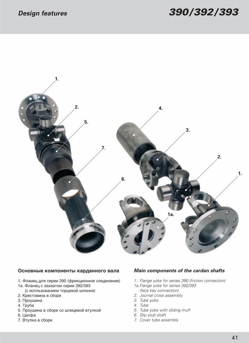
������� �� ������� ���������� ��
1. î·̈ ‰Îfl ÒÂËË 390 (ÙË͈ËÓÌÌÓ ÒÓ‰ËÌÂÌËÂ)1‡. î·̈ Ò Á‡ı‚‡ÚÓÏ ÒÂËË 392/393
(Ò ËÒÔθÁÓ‚‡ÌËÂÏ Úӈ‚ÓÈ ¯ÔÓÌÍË)2. äÂÒÚÓ‚Ë̇ ‚ Ò·ÓÂ3. èÓÛ¯Ë̇4. íÛ·‡5. èÓÛ¯Ë̇ ‚ Ò·Ó ÒÓ ¯Îˈ‚ÓÈ ‚ÚÛÎÍÓÈ6. ñ‡ÔÙ‡7. ÇÚÛÎ͇ ‚ Ò·ÓÂ
Main components of the cardan shafts
1. Flange yoke for series 390 (friction connection)1a.Flange yoke for series 392/393
(face key connection)2. Journal cross assembly3. Tube yoke4. Tube5. Tube yoke with sliding muff6. Slip stub shaft7. Cover tube assembly
1.
2.
5.
7.
6.
1a.
1.
2.
3.
4.
GWB_Rus_prav.qxd 5/4/08 6:18 PM Page 43
42
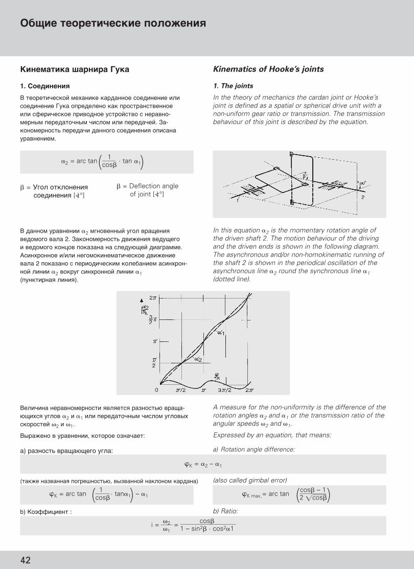
�2 cos�i = =�1 1 – sin2� · cos2�1
����� �������$����� ��������
3��� ����� ������� G���
1. ����������
� ���� ����� "��� � �������� ��� �� � ��� �� '��� ������ ��� ������������� � �(� ���� � ����� ���������� � ������-"���" ��������" � ���" � �����. C�-����"�����- ���� ������� ��� �� � � ���� ������ ".
Kinematics of Hooke’s joints
1. The joints
In the theory of mechanics the cardan joint or Hooke’sjoint is defined as a spatial or spherical drive unit with anon-uniform gear ratio or transmission. The transmissionbehaviour of this joint is described by the equation.
� �����" ������ �2 "�������� ���� ���$� ����"��� ���� 2. C�����"�����- �� !� � ���$�� ���"��� ������ ������� �� �����$� � ����"".�� ������� / � ���"�� �"�� ���� �� !� ���� 2 ������� � � �� ��� " ������ " �� �����-��� � � �2 ������ � �������� � � �1(���� ���� � � �).
In this equation �2 is the momentary rotation angle ofthe driven shaft 2. The motion behaviour of the drivingand the driven ends is shown in the following diagram.The asynchronous and/or non-homokinematic running ofthe shaft 2 is shown in the periodical oscillation of theasynchronous line �2 round the synchronous line �1(dotted line).
� = G��� ������� � ��� �� � [<)°]
� = Deflection angle of joint [<)°]
�� � �� ������"����� ������� �������-� ���$�-�$ ��� ����� �2 �1 � ��������" � ���" ��������������� �2 �1.
����!�� � ������ , ������ �������:
A measure for the non-uniformity is the difference of therotation angles �2 and �1 or the transmission ratio of theangular speeds �2 and �1.
Expressed by an equation, that means:
�K = �2 – �1
1�K = arc tan · tan�1 – �1(cos� ) cos� – 1�K max.= arc tan (2 �cos�)
a) �������- ���$��$�� ����: a) Rotation angle difference:
(���! ��������� ���<����-�, ��������� �������" �������) (also called gimbal error)
b) Ratio:b) D�?(( � �� :
1�2 = arc tan · tan �1(cos� )
GWB_Rus_prav.qxd 5/4/08 6:18 PM Page 44
43
General theoretical directions
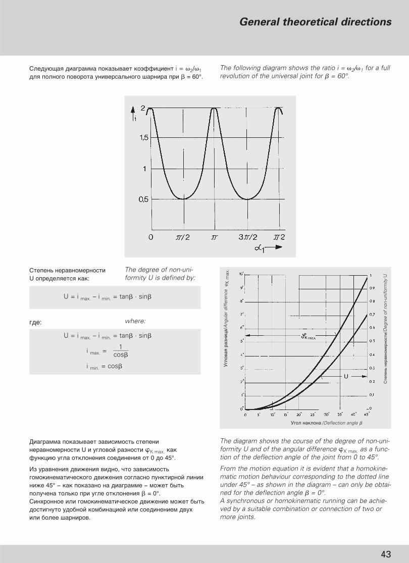
U = i max. – i min. = tan� · sin�
U = i max. – i min. = tan� · sin�
1i max. = cos�
i min. = cos�
��: where:
)��- ������"����� U �������� ���:
The degree of non-uni-formity U is defined by:
� ����""� �������� ��� � "���- ��� ������"����� U ������� ������� �K max. ��� (���� � ���� ������� � ��� �� � �� 0 �� 45°.
#� ������ � �� !� � � ���, ��� ��� � "���- ��"�� �"�� ������ �� !� � �������� ���� ���� � � � ! 45° − ��� ������� �� � ����"" − "�!� ���-������ ���-�� � ��� ������� � � = 0°.) ������� � ��"�� �"�� ���� �� !� "�!� ���-‰ÓÒÚË„ÌÛÚÓ ������� ��"� ��� � � ��� �� " ���� � ��� <��� ���.
The diagram shows the course of the degree of non-uni-formity U and of the angular difference �K max. as a func-tion of the deflection angle of the joint from 0 to 45°.
From the motion equation it is evident that a homokine-matic motion behaviour corresponding to the dotted lineunder 45° – as shown in the diagram – can only be obtai-ned for the deflection angle � = 0°.A synchronous or homokinematic running can be achie-ved by a suitable combination or connection of two ormore joints.
GWB_Rus_prav.qxd 5/4/08 6:18 PM Page 45
������#�� �������� � �������� � $�������� i = �2/�1 ��� � �� � � � �� ��������� � "���� �� � = 60°.
The following diagram shows the ratio i = �2/�1 for a fullrevolution of the universal joint for � = 60°.
%� � ���� �� /Deflection angle �
%��
���
��
��ˆ�
/Ang
ular
diff
eren
ce�
K m
ax.
���
���
��
���
��
� ��
�/D
egre
e of
non
-uni
form
ity U

44
GWB_Rus_prav.qxd 5/4/08 6:18 PM Page 46
����� ����������� ��������/���������� �������� ��� ��������General theoretical directions/Technical directions for application
������ ����
�������� ���� ����� �� ��� Z- � W-��������� .�� ������ � ���� ������������, ��� ������, � ������� ���� ������������, �������� � ��� �����������.
Operating angles
The most common arrangements are the Z- and W-de-flections. To begin with, we will consider the system inwhich the shafts to be connected are in the same plane.
������������ �� ������� ������� ����!�
������� (�1 = �2) �� ��� ���� �� �������� ������������ ���������� ������� �������� ��������, �� �� ���������� ������ ��� . !�"��� ������������ � �������� ����� ����� �����#����� ��������� �����$� ��������� ��������� ����� #�������.
���� ��������� �� ������� ���� �� ������ � ���������������� �������� �#�� ������ ���� �����.%��� ���, �����$� ������ ���� ���������� 1° - 1,5°.
Maximum permissible angle difference
The condition �1 = �2 is one of the essential require-ments for a uniform output speed condition and cannotalways be fulfilled. Therefore designers and engineerswill often ask for the permissible difference between thedeflection angles of both joints.
The deflection angles for high-torque and high-speedmachine drives should be equal. If not, the differenceshould be limited to 1° – 1.5°.
Z-����/-arrangement W-����/-arrangement
2. The universal shaft
The rotation angle difference �K or the gimbal error of a deflected universal joint can be offset under certaininstallation conditions with a second universal joint. The constructive solutions are the following:
1) The deflection angles of both joints must be equal, i. e. �1 = �2
Two arrangements are possible:
2. "����������� ���
&������� ���� ������ �K ��� �����#����� ��−��������� �������������� #������ ���� ���� ����-��� ��� ������ ��������� ������� �������. #������.'������������� ��#��� ��������:
1) ����� ������� ����� #������� ������� ���� ������.�. �1 = �2
(������ ��� ����:
2) ��� #������ ������ ���� �������������������� �� �� 90°, �� ���� ����� ������������������� �� � ����� ���������.
�� ����� ������������ ������� ����������������������� #������ � ��������� ���������� � ���������� � VDI 2722, � ����� � �������������� ����������� �����������.
2) The two joints must have a kinematic angular relati-onship of 90° (�/2), i.e. the yokes of the connectingshaft are in one plane.
For a more intensive study of universal shaft kinematicswe refer you to the VDI-recommendation 2722 and tothe relevant technical literature.
1 b) W- ��� M-����������W- or M-deflection
(���������$Driven end
1 a) Z-����������Z-deflection
!�������� ����$Driving end

45
Technical directions for application
"�"��� ��� ����� ���� ����.
%��� "��-��� ����� "�� ���� ������� � � ��-������ ������� ����� �� � ���������� ���� "�!� ���- ����� �:
and the moment of inertia of the middle part of theshaft.
The maximum permissible deflection angle at a givenspeed and an average cardan shaft length can be deter-mined from:
��� ������� ����� �, �!�������, ���! ��- � ��" . For exact determination please contact us.
n = Operating speed [rpm]� = Deflection angle of joint [<) °]
n = ������� �������- [min–1]� = G��� ������� � ��� �� � [<) °]
#���������� �������� � ��� ���������= n . �
D = n . �
GWB_Rus_prav.qxd 5/4/08 6:18 PM Page 47
Product of speed and deflection angle
= n . �
������� ����� (3° - 5°), ���������� ��� ������������ �������������! ���������!. ��� �������� � ����������� ��������� ���������� ����� �������� �����������, ���� ��������, �� �������������.
"��������� � ���! ���������! ��������, ��� ���������� ��#������� �� �������� � ����������. $�������� ���! ���������! ����� ��������� (Z/Z) ��� W/W) � ���������! ����� ���������� ��������� �����������. ��� ������������� Z- � W-��������� ��������� !����� ������ �������#���. %����� ���, ������������ ���� � ����-����� GWB � ��������� ���� ���#����.
Greater differences about 3° to 5° are acceptable with-out disadvantages in low speed applications. For applica-tions with varying deflection conditions it is important toobtain uniformity, if possible over the complete deflec-tion range.
Deflection in two planes means that the deflection isboth horizontal and vertical. The combination of twoidentical types of deflection (Z/Z or W/W) and identicaldeflection angles ensure uniformity. For combination ofZ- and W-deflection the inner yokes must be offset.Please consult GWB’s application engineers to determi-ne the proper amount of angular offset.
��������� �� ��������� ���������� ������������ �� ����� �
B ����������� �� ���� ��������� ���� ����������� ���� ���������� �� ���������� 5° - 44°. &�-�� ������-�������! ��� ��� �������! ��������� , ��� ������� ����, ���� ���������� ������ ���� �������� � ������������ �� �������'.
*������ � ����'����� �����! �������� ��������-'�, ��� ������ ����#�� ������� ��������� ���������������� ����� �� ������ ���� �������� ��� ����,����� ����������� ������ !�� �������! ������.����� ����������� ����#� ������ ������� ��
Determination of the maximum permissible opera-
ting deflection angle �
Depending on the cardan shaft series the maximumdeflection angle per joint is � = 5° – 44°. Due to the kine-matic conditions of the cardan joint, as described before,the deflection angle must be limited in relation to thespeed.
Calculations and observations of many applications haveshown that certain mass acceleration torques of the cen-tre part must not be exceeded in order to guaranteesmooth running of the drive systems. This accelerationtorque depends on the

46
G��
� �
���
���
� �
Def
lect
ion
angl
e �
)������- n [�� /" �]Speed n [rpm]
%����$����� �������� �� ��� ������
Limits for the product of operating speed and deflection angle
#�������� ���$���� ����$�� �������� � ��� ���������
687/688.15 687/688.20
687/688.25
687/688.30 687/688.35
390.60 392.50 587.50 587.55 587.60 687/688.65
390.70 392.60
390.65 392.55
390.80 392.70
390.75 392.65
687/688.40
687/688.45
687/688.55
GWB_Rus_prav.qxd 5/4/08 6:18 PM Page 48

47
Technical directions for application
��������èÓ‚Â͇ ÍËÚ˘ÂÒÍÓÈ ÚÓÒËÓÌÌÓÈ ÒÍÓÓÒÚË
ᇂӉ ËÎË ÔÓËÁ‚Ó‰ËÚÂθ ‡‚ÚÓÏÓ·ËÎfl ‰ÓÎÊÌ˚ Ì ‰ÓÔÛÒ͇ڸ˝ÍÒÔÎÛ‡Ú‡ˆËË Í‡‰‡ÌÌ˚ı ‚‡ÎÓ‚ ‚ ‰Ë‡Ô‡ÁÓ̇ı ÍËÚ˘ÂÒÍÓÈÚÓÒËÓÌÌÓÈ ÒÍÓÓÒÚË ÔË‚Ó‰‡. ÑÎfl ˝ÚÓ„Ó ÌÂÓ·ıÓ‰ËÏÓÓÔ‰ÂÎËÚ¸ ‰Ë‡Ô‡ÁÓÌ˚ ÍËÚ˘ÂÒÍÓÈ ÚÓÒËÓÌÌÓÈ ÒÍÓÓÒÚËÔË‚Ó‰ÌÓÈ ÒËÒÚÂÏ˚. á̇˜ÂÌËfl ‰Îfl ÏÓÏÂÌÚÓ‚ Ë̈ËË ËÊÂÒÚÍÓÒÚË ÔË ÍÛ˜ÂÌËË ‚˚·‡ÌÌÓ„Ó Í‡‰‡ÌÌÓ„Ó ‚‡Î‡ ÏÓÊÌÓ̇ÈÚË ‚ Ú‡·Îˈ ÚÂıÌ˘ÂÒÍËı ‰‡ÌÌ˚ı ËÎË Á‡ÔÓÒËÚ¸ Û Á‡‚Ó‰‡-ËÁ„ÓÚÓ‚ËÚÂÎfl.
èÓ‚Â͇ ÍËÚ˘ÂÒÍÓÈ ÒÍÓÓÒÚË ËÁ„Ë·‡á‡ ËÒÍβ˜ÂÌËÂÏ ÍÓÓÚÍËı Ë ÊÂÒÚÍËı ÍÓÌÒÚÛ͈ËÈ Í‡‰‡ÌÌ˚‚‡Î˚ Ô‰ÒÚ‡‚Îfl˛Ú ÒÓ·ÓÈ „Ë·ÍË ÏÓ‰ÛÎË, ˜¸Ë ÍËÚ˘ÂÒÍËÂÒÍÓÓÒÚË ËÁ„Ë·‡ Ë ÍÓη‡ÌËfl ËÁ„Ë·‡ ‰ÓÎÊÌ˚ ·˚Ú¸ ÔÓ‚ÂÂÌ˚.ÑÎfl ˝ÚÓ„Ó ‚‡ÊÌ˚ Ô‚‡fl Ë, ‚ÓÁÏÓÊÌÓ, ‚ÚÓ‡fl ÍËÚ˘ÂÒÍËÂÒÍÓÓÒÚË ËÁ„Ë·‡.Ç ˆÂÎflı ·ÂÁÓÔ‡ÒÌÓÒÚË Ï‡ÍÒËχθÌÓ ‰ÓÔÛÒÚËχfl ‡·Ó˜‡flÒÍÓÓÒÚ¸ ‰ÓÎÊ̇ ·˚Ú¸ Á̇˜ËÚÂθÌÓ ÌËÊ ÍËÚ˘ÂÒÍÓÈÒÍÓÓÒÚË ËÁ„Ë·‡.
äËÚ˘ÂÒ͇fl ÒÍÓÓÒÚ¸ ËÁ„Ë·‡ ‰Îfl ‚‡Î‡ ÍÓÌÍÂÚÌÓ„Ó‡Áχ ÓÔ‰ÂÎflÂÚÒfl ÚÓθÍÓ ‰ÎËÌÓÈ Ë ‰Ë‡ÏÂÚÓÏ ÚÛ·˚(ÒÏÓÚË ‰Ë‡„‡ÏÏÛ). èË ·Óθ¯ÓÈ ‰ÎËÌ ‰Ë‡ÏÂÚ ÚÛ·˚‰ÓÎÊÂÌ ·˚Ú¸ Û‚Â΢ÂÌ. ÑˇÏÂÚ ÚÛ·˚ Ó„‡Ì˘Â̇ÁÏÂÓÏ ‚‡Î‡. èÓ˝ÚÓÏÛ ÓÚ‰ÂθÌ˚È Í‡‰‡ÌÌ˚È ‚‡Î ÏÓÊÂÚËÏÂÚ¸ ÓÔ‰ÂÎÂÌÌÛ˛ ‰ÎËÌÛ. é·ÓÛ‰Ó‚‡ÌËÂ, Ô‚˚¯‡˛˘Â‰‡ÌÌÓ ӄ‡Ì˘ÂÌËÂ, ‰ÓÎÊÌÓ ·˚Ú¸ Ó·ÓÛ‰Ó‚‡ÌÓÒÂ͈ËÓÌËÓ‚‡ÌÌ˚ÏË ÔË‚Ó‰Ì˚ÏË ÎËÌËflÏË.
ÑÎfl ÓÔ‰ÂÎÂÌËfl ÍËÚ˘ÂÒÍÓÈ ÒÍÓÓÒÚË ËÁ„Ë·‡ ÒÏÓÚËÒÎÂ‰Û˛˘Ë ‰Ë‡„‡ÏÏ˚.
чÌÌ˚ ‰Ë‡„‡ÏÏ˚ ÔËÏÂÌfl˛ÚÒfl ÚÓθÍÓ Í Í‡‰‡ÌÌ˚Ï‚‡Î‡Ï, ÍÓÚÓ˚ ÏÓÌÚËÛ˛ÚÒfl Ò ÓÔÓ‡ÏË Ì‡Á˙ÂÏÌÓ„ÓÔÓ‰¯ËÔÌË͇, ‡ÒÔÓÎÓÊÂÌÌ˚ÏË fl‰ÓÏ Ò Ù·̈ÂÏ.
ÑÛ„Ë ÛÒÚÓÈÒÚ‚‡, ̇ÔËÏ ÛÁÎ˚ Ò ˝Î‡ÒÚ˘Ì˚ÏËÓÔÓÌ˚ÏË ÔÓ‰¯ËÔÌË͇ÏË, ‰ÓÎÊÌ˚ ËÏÂÚ¸ ·ÓÎÂÂÌËÁÍË ÍËÚ˘ÂÒÍË ÒÍÓÓÒÚË ËÁ„Ë·‡.
Ç Á‡‚ËÒËÏÓÒÚË ÓÚ ÚËÔ‡ Á‡‚Ó‰‡, ‚ÓÁ·ÛʉÂÌËfl ‚ÚÓÓ„ÓÔÓfl‰Í‡ ÏÓ„ÛÚ ‚˚Á˚‚‡Ú¸ ÍÓη‡ÌËfl ËÁ„Ë·‡. ÖÒÎË Û„ÓÎÓÚÍÎÓÌÂÌËfl Ô‚˚¯‡ÂÚ 3° ÔË ·Óθ¯ÓÈ ‰ÎËÌÂ, ÚÓÌÂÓ·ıÓ‰ËÏÓ Ó·‡ÚËÚ¸Òfl Í Ì‡¯ËÏ ÒÔˆˇÎËÒÚ‡Ï.
SpeedChecking the critical torsional speed
The plant or vehicle manufacturer has to prevent the use of cardan shafts within the critical torsional speedranges of the drive. Therfore the determination of thecritical torsional speed ranges of the drive system isrequired. The values for the moment of inertia and torsional stiffness of the selected cardan shaft can betaken out of the data sheets or can be supplied uponrequest.
Checking the critical bending speed
Except for short and rigid designs, cardan shafts are fle-xible units with critical bending speeds and flexural vibra-tions that have to be checked. For this, the first and pos-sibly second order critical bending speed is important.
For safety reasons, the maximum permissible operatingspeed must be at a sufficient distance from the criticalbending speed.
The critical bending speed for a particular shaft size isdetermined by the length and the tube diameter only(see diagram). For greater length dimensions the tubediameter has to be increased. The diameter is limitedbecause of the ratio to the shaft size. Therefore singlecardan shafts can only be provided up to a certainlength. All installations exceeding this limit have to beequipped with subdivided drive lines.
For determination of the critical bending speed see
the following selection diagrams.
These diagrams only apply to cardan shafts that areinstalled with solid bearing supports located close to theflange.
Different installations, e. g. units with elastic moun-
ting bearing, must have lower critical bending
speeds.
Depending on the type of the plant, excitations of
2nd order can cause flexible vibrations. Please
contact our engineers if the deflection angle exceeds
3° and at greater length dimensions.
n��./perm. max._~ 0,8 · n�� �./crit.
�� /" �[ rpm ]
GWB_Rus_prav.qxd 5/4/08 6:18 PM Page 49

����� 687/688
Ñˇ„‡Ïχ ÓÔ‰ÂÎÂÌËfl ÍËÚ˘ÂÒÍÓ„Ó ˜ËÒ·ӷÓÓÚÓ‚ ‚‡Î‡ ‚ Á‡‚ËÒËÏÓÒÚË ÓÚ Â„Ó ‡·Â˜ÂÈ ‰ÎËÌ˚
Series 687/688
Determination of the critical bending speed
depending on the respective operating length
B������ �� �� LB [mm]Operating length LB [mm]
��
"�
: 68
7/68
8.45
�11
0 x
5: B
��"
� <
���
�� 6
87/6
88.4
5, �
�<
� �
� �
".�
����
110
""
, ��
�$
��
���
� 5
""
Exa
mpl
e: 6
87/6
88.4
5 –
110
x 5:
Joi
nt s
ize
687/
688.
45, t
ube
oute
r di
a. 1
10 m
m, w
all t
hick
ness
5 m
m
D�
� �
����
���
����
- n �
� �
[��/
" �
]C
ritic
al b
endi
ng s
peed
ncr
it.[r
pm]
LB
M 2M
%����$����� �������� ��� ������
48
687/
688.
15 -
63,
5x
2,4
687/
688.
20 -
76,
2x
2,4
687/
688.
25 -
89
x2,
468
7/68
8.30
- 9
0x
3
687/
688.
35 -
100
x3
687/
688.
40 -
100
x4,
5
687/
688.
45 -
110
x5
687/
688.
40 -
120
x3
687/
688.
45 -
120
x4
687/
688.
55 -
120
x6
687/
688.
65 -
142
x6
GWB_Rus_prav.qxd 5/4/08 6:18 PM Page 50

Technical directions for application
����� 587/390/392
Ñˇ„‡Ïχ ÓÔ‰ÂÎÂÌËfl ÍËÚ˘ÂÒÍÓ„Ó ˜ËÒ·ӷÓÓÚÓ‚ ‚‡Î‡ ‚ Á‡‚ËÒËÏÓÒÚË ÓÚ Â„Ó ‡·Ó˜ÂÈ ‰ÎËÌ˚
Series 587/390/392
Determination of the critical bending speed
depending on the respective operating length
B������ �� �� LB [mm]Operating length LB [mm]
��
"�
: 39
0.60
− 1
67,7
x9,
8: B
��"
� <
���
�� 3
90.6
0, �
�<
� �
� �
".
����
� 1
67,7
""
,��
�$
��
���
� 9
,8 "
"E
xam
ple:
390
.60
– 16
7,7
x 9,
8: J
oint
siz
e 39
0.60
, tub
e ou
ter
dia.
167
,7 m
m, w
all t
hick
ness
9,8
mm
D�
� �
����
���
����
- n �
� �
[��/
" �
]C
ritic
al b
endi
ng s
peed
ncr
it.[r
pm]
LBM 2M
49
GWB_Rus_prav.qxd 5/4/08 6:19 PM Page 51

50
����� ����� ��� �� � "� "� � ���-< ���� ������. ��� � ��!� �, �� �! ��˛��� ���-< �"�� � �� ��, ������� �� �� ���!�� ���- �����-�� ��� " ������", ����� �� !� ���� � ����� ����� "�� ��"���� �� ��.
'������� ��������� ��
����������-�� ��� �� ��������� ����������� ��� ������ "�":! ����� �����- ���-< ����������� �� ��
������� "�� � �� ���������� ��:
䇉‡ÌÌ˚È ��� � ��"!������" ����"
䇉‡ÌÌ˚È ��� � ���"� ��"!������" ����"
2 ��������� ���� � ������" ��"!������" ��< � ��"
This rough rule applies to most of the arrangements. Forapplications where larger length alterations are expectedthe operating length should be chosen in such a waythat the movement will be within the limit of the permis-sible length compensation.
Arrangements of cardan shafts
A tandem arrangement of universal shafts could becomenecessary:! to cope with greater installation lengths
Basic forms of shaft combinations:
Universal shaft with intermediate shaft
Universal shaft with two intermediate shafts
2 universal shafts with double intermediate bearing
.������� ��� ���
� ���� ���"�� ͇‰‡ÌÌÓ„Ó ���� �����˛���:! �������� " "!�� ���$ " ���"�" "�����" ! ��"���� � �� �� �� ��"� ������
#���-��˛��� ����˛$ �����$� �:
Lz = ���� ����� ���������J�� ��"�� �������� �� �� ����. ���-��< �!�� ����"�!��.
La = �� �������� ����䇉‡ÌÌ˚È ‚‡Î ‡Á‰‚Ë„‡ÂÚÒfl ̇ ˝ÚÛ ‚Â΢ËÌÛ.è‚˚¯ÂÌË ‰‡ÌÌÓ„Ó Á̇˜ÂÌËfl Ì ‰ÓÔÛÒ͇ÂÚÒfl.
Lz + La = ,���. ������� �� ����$�� ���� LBmax.
Length dimensions
The operating length of a universal shaft is determined by:! the distance between the driving and the driven units! the length compensation during operation
The following abbreviations are used:
Lz = Compressed length
This is the shortest length of the shaft. A further com-pression is not possible.
La = Length compensation
The universal shaft can be expanded by this amount. An expansion beyond that dimension is not permissible.
Lz + La = Max. perm. operating length LBmax.
ÇÓ ‚ÂÏfl ‡·ÓÚ˚ ͇‰‡ÌÌ˚È ‚‡Î ÏÓÊÂÚ ·˚Ú¸ ‡Á‰‚ËÌÛÚ ‰Ó Û͇Á‡ÌÌÓÈ ‰ÎËÌ˚. E� "��-��� ��������� �� LB ���� �����, �� ��"���� � �� �� ���� ���� �� ���� ���- ���� �� ��.
During operation the universal shaft can be expanded up to this length. The optimum working length LB of anuniversal shaft is achieved if the length compensation is extracted by one-third of its length.
LB = Lz + 13 La [mm]
%����$����� �������� ��� ������
Lz LB max = Lz + La
GWB_Rus_prav.qxd 5/4/08 6:19 PM Page 52

�FRL = T · · cos �rm
GWB_Rus_prav.qxd 5/4/08 6:19 PM Page 53
51
Technical directions for application
In such arrangements the individual yoke positions anddeflection angles should be adjusted with regard to oneanother in such a way that the degree of non-uniformity(see general theoretical directions) and the reaction for-ces acting on the connection bearings (see technicaldirections for applications) are minimized.
��� ���� ������ ���� �������������� ���� ���� ������ � ����� ���������� ��� �� ���� ������������������ ����������� ����� ���� ������, ����� ������������������� (������ ������������ ���� ����) � ��� ������� �� ������������� ���������� �������������.
�������� � �� ��� �������� �������
������ �������
��� ���������� ���������� ���� ��� �� ���� ������� �� ������� ��������� ����� ��������. ��� ��� �� ���� ��������� ������� ���-�������� ������������� �����!.����� �������� � �������� ���� ��������� �� ���� �������� �����. �������������� ������������� ������� ���������� ��������� ����� � ���������� �������� �� ���� ���� ��������. ������ �������� ����� �������� ����������� � � �� ���� ������� ��������! ������������������.����� �������� "k ������� ���������! ���� �����������:
1. ���� ����� FRL
������ ��� ��������� � ���������� �����. ��� � �� ���� ���������� ��:
Load on bearings of the connected units
Axial forces
For the design of a cardan shaft it must be taken intoaccount that axial forces can occur. These must beabsorbed by axial thrust bearings of the connected units.
Axial forces will occur during length variations in thecardan shaft. Additional axial forces are caused increa-sing torque and by increasing pressure during lubricationof the splines. This force will decrease automatically andcan be accelerated by the installation of a relief valve.
The axial force Ak is a combination of two components:
1. Frictional force FRL
This is the force that occurs in the length compensation.It can be determined from:
FRL = #��� ������ ���������� ����� [$]
��� ������ ��:
T = %�������� ����� ���������� ���� [$]rm = $��������� ������ ���� ���� � ��������� �����
���������� ���� []� = %�˝&&������� ������ (������ �� ��������� �����):
! 0,08 ��� ����� �������� �������! 0,11 ��� ����/���� (�������)
� = '������� ���� ����������
2. ���� Fp
������ ��� ��������� � ���������� ����� ��-�� ���������� �������� � ������� ������� ���-������� ����.#��� ������ �� �������� ���� (��������� �������� �������� 15 ���).
FRL = Frictional force from the length compensation [N]
It depends on:T = Torque of the cardan shaft [Nm]rm = Pitch circle radius in the sliding parts of the cardan shaft [m]� = Friction coefficient (depends on spline-treatment):
! 0,08 for plastic-coated splines! 0,11 for steel/steel (greased)
� = Operating deflection angle
2. Force Fp
This force occurs in the length compensation due to theincreasing pressure in the lubrication grooves of thecardan shaft.
The force depends on the lubrication pressure (max.perm. pressure 15 bar).

52
%����$����� ��������
Universal shaft in Z-
arrangement
Position 0°, flange yoke right-angled to drawing planePosition �/2, flange yoke in drawing plane
䇉‡ÌÌ˚È � Z-��� �����!� 0°, ��"�� (�������� ������ ������� � ���������!� �/2, ��"�� (������ ������� � �����
Calculation scheme of radial forces on connecting bearings)�"� ������ ����� �������� �� ��� � ��-��� ��< � ���
Universal shaft in W-
arrangement
Position 0°, flange yoke right-angled to drawing planePosition �/2, flange yoke in drawing plane
䇉‡ÌÌ˚È � W-��� �����!� 0°, ��"�� (�������� ������ ������� � ���������!� �/2, ��"�� (������ ������� � �����
� = 0°
� = 90°
� = 0°
� = 90°
cos�1 · b� = 0° A1 = T · · (tan�1 – tan�2)L · a
cos�1 (a + b)B1 = T · · (tan�1 – tan�2)L · a
cos�1 · eF1 = T · · (tan�1 – tan�2)L · f
cos�1 (e + f)E1 = T · · (tan�1 – tan�2)L · f
tan�1� = �/2 = 90° A2 = B2 = T · a
sin�2F2 = E2 = T · f · cos�1
cos�1 · b� = 0° A1 = T · · (tan�1 + tan�2)L · a
cos�1 (a + b)B1 = T · · (tan�1 + tan�2)L · a
cos�1 · eF1 = T · · (tan�1 + tan�2)L · f
cos�1 (e + f)E1 = T · · (tan�1 + tan�2)L · f
tan�1� = �/2 = 90° A2 = B2 = T · a
sin�2F2 = E2 = T · f · cos�1
��� � ͇‰‡ÌÌÓ„Ó �� �1 = �2� ���� � ��� � ��������� a = f, b = e� ���� � ���������� � ����������Universal shaft arrangement withequal deflection angles and equal bearing distances
� = 0° A1 = F1 = B1 = E1 = 0
tan�1� = �/2 = 90° A2 = B2 = T · a
tan�1F2 = E2 = T · a
��� � ͇‰‡ÌÌÓ„Ó �� �1 = �2� ���� � ��� � ��������� a = f, b = e� ���� � ���������� � ����������Universal shaft arrangement withequal deflection angles and equal bearing distances
sin�1 · b� = 0° A1 = F1 = 2T · L · a
sin�1 (a + b)B1 = E1 = 2T · L · a
� = �/2 = 90° )". Z-��"� � = �/2see Z-arrangement
GWB_Rus_prav.qxd 5/4/08 6:19 PM Page 54

53
����"�� �-�� �����, ����-� ����, ��"���� ����,���� � �����, ��������/� ���� ����� ������������ 4−� �������� �� ����� (��� � � � ��-) � 6−� ��� � � ����" , ��������/� ���� �� ����� "�< �, ������ ��� ����"�� ���
���� � ����� (����� ����, �������� ����) � �����" ������� �" , ���� ���� ��� ��-���"�< �E���-�� ��"����� �� ����� (��� � � ��- ) ��� "�< �, ������ ��� ����"�� ���D�������/� ���� �� ����� � <��-� ��� � � ����" �� �� ��-��" ������� �"
Q��� "�< � ��������� �� ��������L���� ������� "���� � ���� � (���� ����(����)��� ������, "���� � , �������� ���� (������ ��"�!��� "�< �, ����� ����P����� ������� ���� � ��"����� � ����D���-���� �������
'����� ����� ���� ��, ������� "���� ���� ��(��-�� ����(����)S��� ������ ��������������;������"������, ������������� ���� �������*������� � �� �"�� ��"-�����
Car wheels, wheel rims, wheel sets, drive shaftsCrankshaft/drives of elastically mounted fast four- cycle engines (gasoline or diesel) with six or more cylindersCrankshaft/drives of engines of cars, trucks and locomotives
Drive shafts (propeller shafts, cardan shafts) with special requirementsParts of crushing machines and agricultural machineryIndividual components of engines (gasoline or diesel) for cars, trucks and locomotivesCrankshaft/drives of engines with six or more cylinders under special requirements
Parts of process plant machinesMarine main turbine gears (merchant service)Fans, flywheels, centrifuge drumsPaper machinery rolls, print rolls Assembled aircraft gas turbine rotorsPump impellers
Gas and steam turbines, including marine main turbines (merchant service)Rigid turbo- generator rotors Turbo- compressors, turbine- driven pumpsMachine- tool drives ����!�� � DIN ISO 1940/����-1Computer memory drums and discs Extract from DIN ISO 1940/Part 1
G 40
G 16
G 6,3
G 2,5
Technical directions for application
<��������� ���������� ��
*����� ����� ��������� ����� �� ���� ��� ��� ��-���� ��� � ?������ ��� �� !�$ ��� "���, �"��"�" �������$�� � ���� ˛ �"�-<�� �������� �� �� ����� ���� ���������� .*����� ����� ��������� � ��������� �� ����-�����" #)E 1940, "D������ ������ ���� ���$�˛$ ��� ������ ��". )������� ?��"� ��������� ����� "������������ � ������� ��� � � �� ������ ������� "���� ������ �������� ��"������.&�< ��� ��������, ��� ������ ����� ������ � ������� ��� �������� ���$� � � ! 500 ��/" �.� ������� ������� ������ � ����� "�!� ���-��� �� � �"�-<� � ��� � "��� �� ��$ ������" �� ����� ������� �� �.D������� ���� ������ ������ � ���� ���������,������ �� ������� ������ ���� G16 G40.
! �������� ����������
)������- ������ ���� - ?��, ������, "��� "��-��� �������- � ��"� � ������������ �������.
! '����� ��$����
�� ����� ������ ������� ������ "� ���-�"��� ���- �����- ������"��� , ���� ! "�� �� ����-��-��" ���� ������ �� �� ��"� ��������� ������ �.G����- ������� ��� � � �� ����˛$ � �� � �:− � ������ �������� "�< �� (!�����, ������ �
"����� ������)− �������- �"� ��-��� � ��"�− ����� � ��������− ������� �˛(� � �"$� � �����-��"
������� .���� �� � ˝�������� ����� ����� �� �������˛�, ��� ��""�?� � (������� "�!� � ��� � ���<���� �� 100%. ����� ��������-���� ������ ����˛$ ����� ��-����� ������ ���� :
− ������ ����� �� ���� ���: G16− �������� ����� � ������ ��: G32
Balancing of cardan shafts
The balancing of cardan shafts is performed to equalizeeccentrically running masses, thereby preventing vibrationsand reducing the load on any connected equipment.
Balancing is carried out in accordance with ISO Standard1940, “Balance quality of rotating rigid bodies”. Accordingto this standard, the permissible residual unbalance isdependent on the operating speed and mass of the balan-ced components.
Our experience has shown that balancing is not normallyrequired for rotational speeds below 500 rpm. In individualcases this range may be extended or reduced, dependingon the overall drivetrain characteristics.
Cardan shafts are balanced in two planes, normally to abalancing accuracy between G16 and G40.
! Balancing speed
The balancing speed is normally the maximum speed ofthe system or vehicle.
! Quality grade
In defining a quality grade, it is necessary to consider thereproducibility levels achievable in the customer’s owntest rig during verification testing. Quality grades aredependent on the following variables:– type of balancing machine (hard, rigid or soft suspension)– accuracy of the measuring system– mounting tolerances– joint bearing radial and axial play– angular backlash in longitudinal displacement direction
Field analyses have shown that the sum of these factorsmay result in inaccuracies of up to 100%. This observationhas given rise to the definition of the following balancingquality grades:
– producer balancing: G16– customer verification tests: G32
GWB_Rus_prav.qxd 5/4/08 6:19 PM Page 55

TDSch = 1,4 · TDW
&���� ��������� ��
GWB_Rus_prav.qxd 5/4/08 6:19 PM Page 56
54
������������ ���� � �� ������ ����˛��� �� ������ � ����� ���������� �˛��� � ������� ������ ���� � ������ � ��� ����, ���� ������� ������ �� ������ (��. ������� � ��������������������� / ���������� �� ������� �����������).
�������� ���, ������ ����� ���, ������� ������ ����� ������������. ��������, �������� ������ ��������� ��� ����������� ������������ �����������.
����� ������� �� � � �� ���� ����� � � ��˛��� �� �����:
1. �����!����� ����� � ��2. " ��� �� ����� ����� ����������3. #�������� $���������4. %����� ��� 5. ��������6. &����� � ����� 7. #����� � ���������� ������������ � �������
1. �����!����� ����� � ��TCS = '���������� � ����� ��������� ������ [#�]
�� ���� ������� ���� ���������� ��������� ������������� ����� ���� ��� ���� � ������� �� � � ����-����� �������� ��� ̇ۯÂÌËfl ÙÛÌ͈ËË ÔÓÒ‰ÒÚ‚ÓÏÓÒÚ‡ÚÓ˜ÌÓÈ ‰ÂÙÓχˆËË ÓÒÌÓ‚Ì˚ı ÙÛÌ͈ËÓ̇θÌ˚ı ÛÁÎӂ͇‰‡ÌÌÓ„Ó ‚‡Î‡. èË ‰‡ÌÌÓÏ Á̇˜ÂÌËË Tcs ‚‡Î ‚˚‰ÂÊË‚‡ÂÚ‰Ó 1000 ÒÏÂÌÌ˚ı ͇ÚÍÓÒÓ˜Ì˚ı ̇„ÛÁÓÍ. ùÚÓ Ì ‚˚Á˚‚‡ÂÚ� ���� � ���� � ���� ���������.
*������� ������ ���������
���� ������ ��������� ������ ���� � ����������� ���������� ������!��� ������� �� �, ��� ����� ������� ��������� ���� ������� �������.
TDW = %������ � �������� � �������� ������ [#�]
"�� ��� �������� ������ ������ �� ��������������� � ������������ ��������. #����� � ������ �� �� ����� 687/688 � ���������� �� �����-������ � ������� ���."�� ���� ����� �������� ������� ���� ���������������� ������� � �!���� ������� � ������ ��������.
TDSch =������������ �������� � �������� ������ [#�]
"�� ��� �������� ������ ������ �� ������� �������� ��� � ��˛��� �� �����˛��� ��������.
LC = *��!!������ ������� ���������
$�%���!��� ������� �������� �������� �������� ���������� ���� � ���� Cdyn (��. DIN/ISO281) ��������� � ��������& ������� R.#����� LC � ��� ���� �������� �� �� ������� ���� �!� (��. ���!�����!��).
+�� ��� �������� � ���� ����� ����������� ����� ��������� ����� ����������� ��������." ���������� � ���������� ������� ������� ��������� � �������� ������ ��� ��������˛����������� ������ ����� � �� ������ � ������.
The designing of cardan shafts must exclude all pos-sible danger to persons and material by secured cal-culation and test results as well as other suitablesteps (see installation and maintenance/safetyinstructions).
The selection procedure described in this chapter isonly a general recommendation. Please consult ourengineers for the final design.
The selection of a cardan shaft should be based on thefollowing conditions:
1. Specifications of cardan shafts2. Selection by bearing life3. Operational dependability4. Operating angles5. Speed6. Length dimensions7. Load on bearings of the connected units
1. Specifications of cardan shafts
TCS =Functional limit torque [Nm]
Up to this maximum permissible torque a load may beapplied to a cardan shaft for a limited frequency withoutthe working capability being affected by permanentdeformation of any cardan shaft functional area. Up to1000 load changes (short time fatigue strength for finitelife) are capable of being sustained with TCS. This doesnot result in any unpermissible effect on bearing life.
Yield torque
This torque level leads to irreversible plastic deformationof the cardan shaft which could result in a failure of thecomplete drive system.
TDW =Reversing fatigue torque [Nm]
At this torque the cardan shaft is permanently solid atalternating loads.The values for cardan shafts of series687/688 with welded balancing plates are lower.With a fatigue torque of this order the transmissioncapacity of the flange connection must be checked.
TDSch = Pulsating fatigue torque [Nm]
At this torque the cardan shaft is permanently solid atpulsating loads.
LC = Bearing capacity factor
The bearing capacity factor takes into consideration thedynamic service life Cdyn (see DIN/ISO 281) of the bea-rings and the joint geometry R.The LC-values for the different shaft sizes are shown inthe tables (see data sheets).
For selecting a cardan shaft the bearing life and theoperating strength must be considered separately.According to the load state the reversing fatigue torque TDW or the pulsating fatigue torque TDSch
must also be taken into consideration.

55
2. &���� �� ����� ����� ����������
�� ���""������� �������� ���������� LC
)��� ���!�� ��< � �� Lh ���������� ���� ��� � � �� ��?(( � ��� ������� ��< � �� ������� ������˛$� (��"��:
I�� ��� !��"�� ���� ���!�� ��< � �� Lh , �����"� ¯‡Ìˇ "�!� ���- ����� ��� ��� Lc.
C���� � LC "���� ���- ����� � ���� �(�"��� � )� ( ��� ).
LC= D�?(( � �� ������� ��< � ��n = B������ �������- [��/" �]� = B���� � ���� ������� � [<) °]T = B���� � �����$ � "�"�� [�J ]K1 = G������ ��?(( � ��
I�� ����� ����� �������� �� ����� � � ����, �����!�� ���- ����� ���� ��� �����������! ��-����-.
�� ���� � �� �����" ��������� ������ � "���� �������- � �����$ � "�"����, ��������������� � � � ��?(( � ��� D1.
C���� �, �������� � ���� ���, ����˛��� ��$ " ����� �" . I�� ���-����� <��� ��� ��� �� , �� ������� ��?(( � �� � !. � � �� , ������ "����"����- ����� �� ���� ��� �� ����� ��� �� �.
3. J��������� ������
&��!����- ������ "�!� ���- ������, �� ������ ����� ����� � ���. B������� ���� ���!������������ ���� � ���"��-��� ����� � ����� �����!� ���� ����- � ���� �- ����"�� ���� ���!��.
B���� � ��� ����� ��������. � ?��" �����,�!�������, ���! ��- � ��< " �!���" �����-�����- ��< " ��� �" 60-��� " ����" �� �������� ��������� �����. %� ���� "�� "��-��� �����.
&�< ������ �������� �� ����" �����$" "�"�� ; "��� "��-��" ����" �����$" "�"�� TSP, �������"�!� ��� �-��.
� ����� �����$ � "�"�� �������� ������������� � �� ������ ������� �� ��" �����$�� "�"���. E� ���!� ���- � ! �����������$ � TDSch TDW.
2. Selection by bearing life
by bearing capacity factor LC
The bearing life Lh of a cardan shaft depends on the bea-ring capacity factor and is based on the following formu-la:
If the desired bearing life Lh is given, the joint size canbe calculated by the bearing capacity factor LC.
The LC-values can be taken from the tables (see datasheets).
LC= Bearing capacity factorn = Operating speed [rpm]� = Operating deflection angle [<) °]T = Operating torque [kNm]K1 = Shock factor
If operating data are based on a duty cycle, a more preci-se durability can be calculated.
Drives with internal combustion engines may cause tor-que peaks that must be considered by factor K1.
The values shown in the tables are general values. If aflexible coupling is used, the shock factor is lower.Principally the data of the motor and/or coupling manu-facturer must be observed.
3. Operating dependability
The operating dependability can be determined if a cer-tain duty cycle is given. The calculated service life of acardan shaft under normal working conditions has toachieve or exceed the required service life.Duty cycles are often not available. In this case, pleasecontact our engineers and make use of our more than 60 years of experience as a manufacturer of cardanshafts. We will provide an optimal selection.Our calculations are based on the peak torque T and themaximum peak torque TSP that may occur.The peak torque is determined according to the kind ofoperation and the torque characteristic. It should belower than the corresponding torques TDSch and TDW.
LC · 1010Lh = n · � · T10/3 · K1
Lh · n · � · T10/3 · K1LC = 1010
Electric motor/turbine K1 = 1,00Gasoline engine 4 cyl. and more K1 = 1,15Diesel engine 4 cyl. and more K1 = 1,20
J������� ����- /���� �� K1 = 1,00*�� ����� �� ����- 4 � �. ��� K1 = 1,15� ��-��� �� ����- 4 � �. ��� K1 = 1,20
TN . K = T < TDSch � /or TDW
Selection of cardan shafts
GWB_Rus_prav.qxd 5/4/08 6:19 PM Page 57
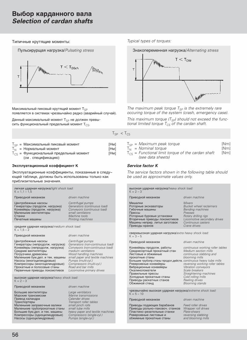
56
TSP < TCS
���-� ���$�� ��������/Pulsating stress C�����"���� ��������/Alternating stress
&���� ���������� ��Selection of cardan shafts
GWB_Rus_prav.qxd 5/4/08 6:19 PM Page 58
������� ����� �� ����/heavy shock load:K = 2 – 3
�������� �������� driven machine
������� Mixers�������� ����������� Bucket wheel reclaimers�������� ������ Bending machines������ Presses�������� ������ �������� Rotary drilling rigs��������� ������ ����������� Locomotive secondary drives������ ������. ���!� �� ������ Continuous casters������ ������ Crane drives
������������ ����� �� ����/extra heavy shock load:K = 3 – 5
�������� �������� driven machine
"�������� �����#. ������ continuous working roller tables$����������� ��������� ���� Medium section mills%������� � ��#����� continuous slabbing and ��������� ����� blooming mills&��!��� ������.����� �����.�����. continuous heavy tube mills����������� ��������� reversing working roller tables�����'������ ��������� Vibration conveyors(�������������� Scale breakers������!��� ������ Straightening machines)������ ��������� ����� Cold rolling mills������ ��������� ������ Reeling drives(�#����� ���� Blooming stands
����������� ������� ����� �� ����/extreme shock load:K = 5 – 10
�������� �������� driven machine
������ ���*+�� ��������� Feed roller drives������ ���!��−�������. ������� Wrapper roll drives��������−�������!��� ������ Plate-shears����������� �������� � reversing slabbing ��#����� ��������� ����� and blooming mills
�� ��� ����� �� ����/light shock load:K = 1,1 – 1,5
�������� �������� driven machine
,�������#��� ������ Centrifugal pumps���������� (�����#. �� ����) Generators (continuous load)"�������� (�����#. �� ����) Conveyors (continuous load)�����!��� ����������� small ventilators$����� Machine tools�������� ������ Printing machines
������ ����� �� ����/medium shock load:K = 1,5 – 2
�������� �������� driven machine
,�������#��� ������ Centrifugal pumps���������� (�������#. �� ����) Generators (non-continuous load)"�������� (�������#. �� ����) Conveyors (non-continuous load)$����� ����������� medium ventilators�� ������ �������� Wood handling machines�����!��� ��.��. � ���. ������ small paper and textile machines0����� (��� �'���������) Pumps (multi-cyl.)"���������� (��� �'���������) Compressors (multi-cyl.)��������� � ��������� ����� Road and bar mills��������� ������ ����������� Locomotive primary drives
������� ����� �� ����/heavy shock load:K = 2 – 3
�������� �������� driven machine
&��!��� ����������� Large ventilators������� ����������� Marine transmissions����� ������� Calender drives1����������� Transport roller tables�����!��� ����������� ������ small pinch rolls�����!��� ������������� ����� small tube mills&��!��� ��.��. � ���. ������ heavy paper and textile machines"���������� (���'���������) Compressors (single-cyl.)0����� (���'���������) Pumps (single-cyl.)
��������!��� ������� ����+�� ������ TSP���������� � �������� ����������� ���� (��������� �����).
2����� ��������!��� ������ TSP �� ��#�� �����-���! 3��'�����!��� �����!��� ������ TCS.
The maximum peak torque TSP is the extremely rareoccuring torque of the system (crash, emergency case).
This maximum torque (TSP) should not exceed the func-tional limited torque TCS of the cardan shaft.
TSP = ��������!��� ������� ������ [0�]TN = 0�����!��� ������ [0�]TCS = 4��'�����!��� �����!��� ������ [0�]
(�� . ���'�3���'�*)
TSP = Maximum peak torque [Nm]TN = Nominal torque [Nm]TCS = Functional limit torque of the cardan shaft [Nm]
(see data sheets)
���������� �� �������� K
5�������'������ ���33�'�����, ���������� � ���−*+�� �����'�, ��#�� ���! �����!������ ���!�� ��� �����������!��� ��������.
Service factor K
The service factors shown in the following table shouldbe used as approximate values only.
1������� ����+�� �������: Typical types of torques:

57
�������ˆ�� �� ������� ������������
&�< ��� � ����������� ������ �������� ��"�" ����"���" ������� �". F�������� ��������� ��� �, ������ � ���� � ��<" �(��"�� ����""��� �� � ������ ���� ������, ��� �����-!��� ����!�$ " �$���-��" ������" .
C����� ����������� �� ����, �� ��� �������˛������ ����� ������ ���� ������ ������������.
C��� � ���� ���� ��������� � ��< � ��� �� ��� �������� � "�� � �! � �� ������ �������� �� ��� ����������- � ����� ���!� ����"���� , ������������ ��" �� ����� ������, ����< � �������" ��� �������, � ����� ������� ��� � ��� ��� �-���� � "�� �. ����� � �� ����� �� ( � ����� � ���"��� � ��<� ������� �� ��� ������� ���� ����"��� ���-�� ���-����� ���"���� �.
�� ���-����� ����$� � ��������" ����" ����˛$ ������� � ��� � ��������� ���!�� ���- ������ ����˛��� ��� �������$� � ���!�� � ������� "�$����
! í‡Ï, „‰Â �������- ��� �˛�� "��� ���� "�!� ���- ������� ���$�˛$ " �� ��������" ����" , ��$ ��� ���������� ���!�� ���- ������������-������" / � �������".���˛����� ����� L� �� �������������!
! G��������, ������ ������ � ��� ����"� �����! ��� ˛ "���� ���- ������� ���-������ ( � �������" �������".
! B���� ������� �� � ��������� �����, ��� ��� "��� "��-��� �����$ � "�"��, �������-,���� ������� �, �� �� �. �., � ����� � ���!�����- ���<��.
! I�� �������� ���� ������ ��� "−� ��������" �� ��<�� �-"����� ������ �, �� �� � � ���-< � �������������� ������ �.
D������� ���� GWB �������˛��� ��� "���� , ������ � ��������. ���� �"����� ��� ������. E� �������� ������ ����<�� � ��������� � ��� ��� " �� ( ��� �" .
����!� ������ ���� ���������� ���� � ���!�� ���- �"���.
� ������� ���� "�!� ������- ������� ��˛ ������ �!���"���� ���� ��� �� � ��< � ��� "�����, � ������" ��������� ��� ����� ��. � ?�������� ������� ��������� ��� "�!� ��������-�� ��"����� ���� "���� ���- �� �������-˛ �����<�� ������������� ������� � "��� �"�.
��������� ����������!������$��� ������� � ��������� �!
���-��< ������� � ��������� � ���� � ����������˛$ � �������.
Safety instructions
Our products have been developed and tested accordingto the latest state-of-the-art engineering. The characteris-tic features of the products which are described in ourinformation material or which we specified in writingwere subjected to proper and careful inspection.
Other features are possible but they are subject to
our written confirmation.
The knowledge of the various demands on our productfor a particular application lies with the purchaser, and itis incumbent on him to verify the drawings and docu-ments prepared by ourselves on the basis of the datamade available by the purchaser and to examine thesuitability of the product for the proposed use. The se-lection of shaft types and the specification of their sizeson our part shall in all cases be considered as a recom-mendation only.
When using and handling cardan shafts, the followingsafety instructions must be strictly observed to preventdamage to persons and property.
! Where danger to people or material can be caused byrotating cardan shafts, a safety device has to be instal-led by the user and/or operator.Observe the EC Regulations for Machinery!
! Installation, assembly and maintenance work mayonly be carried out by qualified personnel.
! The operating data of the cardan shafts, such as max.torque, speed, deflection angles, lengths etc. mustnever be exceeded.
! If cardan shafts are in any way altered without our
written consent, they are no longer covered by
our warranty.
GWB cardan shafts are delivered as complete unitsready for installation. The shafts are greased for operati-on. They are balanced and painted in accordance withthe technical information sheets.
The balance state of a cardan shaft must on noaccount be altered.
An inadmissible out-of-balance of a shaft may resultin uneven running and premature wear of the jointsand the bearings of the units to which the cardanshaft is connected. In extreme cases the cardanshaft could break and shaft components could bethrown at speed from the vehicle or machine.
Danger of injury!
Provide a safety guard device!
Further safety instructions are incorporated in the rele-vant items.
'������� � �����$����� ����������Installation and maintenance
GWB_Rus_prav.qxd 5/4/08 6:19 PM Page 59

� ����� ��� �� �joint range
� ����� ��� �� �joint range
�����/Series 587, 687, 688 �����/Series 390, 392, 393
2 121
'������� � �����$����� ����������
GWB_Rus_prav.qxd 5/4/08 6:19 PM Page 60
58
������������� ������
��� ������������� ���������� ��������� ���������� �������� ����� ��������� ���������˛������������ ������ �������� �����.
��������, �� ������ � ��˛�� � �� �� ���������:
! �������� �� ��� � ������� ��� ��� ���� ��� � ���.��� ������������ ������ ���� ������� � ���.
! �������� ���� ������ ������������� � �������-������ ����� ��� (�. ���˛����˛). ��� � �������-������ ����������� ������� ���� � �� �� �−�������� ������ ��� ������ ‰Îfl ËÒÍβ˜ÂÌËfl‚ÓÁÏÓÊÌÓÒÚË ‡ÒÔ‡‰‡ÌËfl ‚‡Î‡ ̇ ˜‡ÒÚË.�������� ����������!
! ��� ���� � ��� �������� ���� ������� � !�� (���� "����� � �� �����) ���� ������ � ���!���� ���� �� ���.����� ��� �������� � ��������!�������� ������� ���!
! ��� ��� ��!��� � ������ ��� ����������� ����� ���.
! # ����� � � ����� ���� �����−���� ��������� �� ����� $� �� � � (1) � ����� ��� (2)
Transport and storage
To prevent injuries of persons and damage to
the cardan shafts always make sure that the
shafts are safely transported and stored.
Please consider the following precautions:! Use strong nylon ropes or lifting belts. When using
steel cords, protect the edges.! Cardan shafts should be transported in a horizontal
position (see illustration). For non-horizontal transpor-tation additional precautions must be taken to preventthe splined parts from separating.Danger of injury!
! When lifting or putting down the shaft, the movingparts (flange yoke and journal cross) may tilt and leadto injuries.Keep hands away from the joint!
Danger of crushed hands!
! Avoid bumps and knocks during transport and storage.
! Do not store or handle the shaft with any stress orload on the spline protection (1) or the seal (2).
! �������� ��������� ������ � ������� ��� ���-� ���, �� !��� ����� "���� � � ���� ��� ���������
! �������� ����� ��� ������� ��� �� ������ ������� ��� ���������� ����
! %��� �� ��� � ���������, �� �� ������ �� ��������� ����� ���.
! & ��� �������� ���� � ���� � .
! Use appropriate frames or racks for storage, so that the flange yokes are not loaded.
! Use chocks or blocks to prevent cardan shaft from rolling.! Secure shaft against falling over if it is stored in a
vertical position.! Keep cardan shafts in a dry place.

59
'������� � ��������
'�������
��� ����� � ������ ������� � ������� �� � ��������� �����, ��� � ���� � �(��"�� ����� ���−<˛�, �� � ���!�� � �� �"���-�� ��� ������ .
C��� ��� ˛�� �� ������� �� ���� ���� �������������˛�� ��� �������� � �� �, ��������� ����� ����������� ���������˛��� ��� ����������������.
! �������$ ��$ ��� ���������� (��� "�, ��$ ��� ��� , ������ ��$ ��) ���!�� ���- ������������� �������$� � ������ � ����� ���� ����!�.��������� �� �����!
! D������� ���� ����˛��� ?���� ���" � �� " ��� �" . #� �� ��� ������ � � �� � ����� �������- �� ��� � ���!�� ���- ����� ����. %��� "��-������� "�� ������� �������- ���!�� ���- ������������� ! �� � ����� ������� �� ��� � �� �� � ������.
! ��� ������� ���� ��������� ���� ����� n x ß (�������- � ���� ������� �) ����������˛$ ����"��� ����� � ���!�� ���- ���<��.��!�������, ���! ��- � ��" .
! � ��� ������� ������-��� � �"�� (����� ���� (������� ��� �� � ���!�� ���- �������� ������ , �"��� � ����� , ����� ������ �����- ���������� �� �.
! *��-� ������!�� � ����$� � ��������" ����". )������� �� ��˛$ �� ��"��� (����� "���� � � � �- ���!�� �!
! �����-� �� � ˛ ��"��� (1) ����. )���˛����"��� ����� ������ (2). E� ���!�� ���- ��������.���� ����������˛� ���� ����� � ���!�� ���-��"��� � ��� ����.
! ��� ���������� ��� � ���������� ( ���� � �������� ����, �� �� � �������˛�. I�� �� ���������˛�, �!�������, ���! ��- � �����$ ��".
! �����-� ���� ��� ��-�� � � �, � ���! ��� � ����� �� ������������ (������ ����� � ��-��"���� (�". (������ ��� �� �).
! & ������ ���� ��� �� � ��������� ����� ���������" ����<����" , ���"� ��� ?�� "�!� ���� �- � � �"��� � ������ ������.
! #���-���� ���� ����� ������������� �������(������� ) (�". ������� (������ ��� �� �).
Installation/dismantling
Installation
In order to guarantee the properties of the cardanshaft as described in the information brochure theymust not be altered from its as-delivered state.
Whenever people or material might be endangeredby rotating cardan shafts, the user must take for therelevant safety precautions.
! Suitable safety devices (e.g. catch bows, solid safetyguards) must be provided to prevent the parts of theshaft from being thrown around.Danger to life!
! Cardan shafts are elastic and flexural bodies. Their fle-xural vibration and their critical bending speed mustbe calculated. The maximum permissible operatingspeed must be sufficiently below the critical bendingspeed of the first order.
! For the smooth running and safety of the shaft the n x � value (speed x deflection angle) of the relevantshaft size must not be exceeded.Please contact us.
! The faces and the centering diameter of the shaftflanges and companion flanges must be free of dust,grease or paint to guarantee a safe connection.
! Be careful when handling the cardan shaft. Freelymoving flange yokes may cause INJURIES!
! Check position of yokes (1) of the shaft. Observe thearrow markings (2). They must be in alignment. Thesplines are fitted to one another and must not beexchanged or distorted.
! Before installation remove the transport retainer device, if present. In case of doubt please contact thesupplier.
! Check the axial and radial run-out as well as the spigotfit of the mounted flanges and the connected units(see companion flanges).
! Do not turn the joints of the cardan shafts withassembly levers because this may damage the greasenipples or relief valves.
! Use nuts and bolts of the prescribed quality (strength)(see flange boltings).
2
1
Installation and maintenance
GWB_Rus_prav.qxd 5/4/08 6:19 PM Page 61

60
! #���-���� ���� ����� ���-�� � ��������� �� �� ( ��� � �����$ ��.
! *���� ���!�� ���- �����"��� �������� ����−��������� �������" ��˛��" (�". (������ ������� ��� �� ).
! �� ���-����� ��������� ����� �� ��"������� �� ��, �� � � ����� � ��-��� "����� ���!����- � �� " ��� ����, ����� ���- �����������" �(������� �������˛$�. #�"�� � �� ��, ������ "���� ���- ������� �"�������" �"�� �" ,���!�� ���- ����"����� ��� � ��-��" ��< � ��" .
! I�� �������� ���� ���-��˛��� � ��"�������" �� ��, ������� (������ ��� �� � ���!�����- ������ �������� �� ��� � ��-��� "�����������.
! �� ����� ��� 6 "���� �������� ���� ���!�� ���- ������� �"����� �� ���-����� " (�". ��� ���� �����! ��� ).
! �� ������ ��������� ����� �?�����-˛ ��� ��-, ��� � ����� ����-!� � ������ � (��"���� � �� �� La) ������.
! �� ������ ��������� ����� �?�����-˛ "� ���"���" ��< ��������� ������ (��!�������, ����� � �).
! C�$ $��� < ��� , ������ � �����" ("�(��,��"��� "�(�) ��:− ������� �;− ������� ���;− "��� ��� � ���!�� �.
! �� � ��� ��������� ����� � ���-���� ����� ���� " ��� � ���$ ������� � ���� �� ����� ", � ���� ���, ��� ��� ������ � "���� ���-���!��� "�!� ��� ����- ���� � ����-.
! D������� ���� "���� ���- ���-������ � �"�����-��" � ����� �� −25º ) �� +80º ), � ��� ,����� ���� � ��"� � ��� �� +120º ).��!�������, ���! ��- � ��" , �� ������� �"���������������� �� ?� � ����� �.
)�������
! ��� ��������� ��$ � � ��������� ��� ������� � ����.
! E�����-� ��������� ��� �� ��� � �� �����-� ��� " (�������� ��� �� �. F�"�� (����� "�!� ���� ���-��.��������� ����������!
! )���˛���� ��� �� �������� ���� , ����� � �������� ��������� �����.
! Only use nuts and bolts in accordance with the supp-lier’s specification.
! The bolts should be evenly tightened crosswise witha torque wrench (see flange boltings).
! When using cardan shafts without length compen-sation, one of the connecting units must be flexiblein order to be fitted over the flange pilot. Variations inlength which may be caused by temperature changesmust be allowed for by a suitable connecting bearing.
! If cardan shafts with length compensation are used,the companion flanges must be firmly fitted on theshafts of the connected units.
! Cardan shafts that have been stored for more than 6 months must be re-lubricated before use (seeMaintenance).
! For spray-painting the cardan shaft, make sure thatthe sliding range of the seal (length compensation La)is covered.
! For spray-painting the shaft we recommend our paintstandards (Please ask for them).
! Protect rilsan-coated splines (sleeve muff or sleeveyoke) against– heat– solvents– mechanical damage.
! When cleaning cardan shafts, do not use aggressivechemical detergents or pressurized water or steamjets because the seals may be damaged and dirt orwater may penetrate.
! Cardan shafts can be used in a temperature rangebetween –25°C (–13°F) and +80°C (+176°F), up to+120°C (+248°F) but only for limited periods and noton a frequent basis. Please contact us if the operatingtemperature deviates from these values.
Disassembly
! Before disassembly protect the cardan shaft from spline separation.
! Secure the cardan shaft against falling down beforepulling it off the companion flange. The flange yokemay tilt. Danger of injury!
! Observe the directions for transport, storage andinstallation of cardan shafts.
La
'������� � �����$����� ����������
GWB_Rus_prav.qxd 5/4/08 6:19 PM Page 62

61
B��"� ����/Shaft size 587.50 587.55 587.60
� �"�� (�����/Flange dia. A mm 225 250 250 285 285Ta Nm 295 405 405 580 580c mm 158 176 168 202 202c1 mm 171 189 189 214 214d – M 16 M 18 M 18 M 20 M 20l mm 50 60 60 64 64v mm 20 24 24 24 24s mm 24 27 27 30 30i1) – 8 8 8 8 8*���� ��������� �� ������� ��� �� � �� �� �� �� ��Bolts inserted from joint side yes yes yes yes yes
�����/Series 587/687/688
6����������� ���:�������� "���-,�����������$��DIN 931/10.96����������� �����::�����������$��DIN 980/10.)�"�������$����
Hexagon bolt:
short model similar toDIN 931/10.9Hexagon nut:
similar to DIN 980/10,������ ��� �� /Joint flange Self-locking
1) = D�� ����� ������ � ��� ������;� = C���!��� "�"�� ��� ������)� ��-��� ��� �������� �������������� � ������
1) = Number of bolt holesTa = Tightening torque of boltingSpecial torque wrenches supplied on request
c 1s
l
v
dc
2xG
Installation and maintenance
GWB_Rus_prav.qxd 5/4/08 6:19 PM Page 63
������ ���/Shaft size 687/688.15 687/688.20 687/688.25 687/688.30 687/688.35 687/688.40 687/688.45 687/688.55 687/688.65������ ����/Flange dia. A mm 100 120 120 120 150 150 180 150 180 180 225 180 225 180 225Ta Nm 35 69 69 69 120 120 190 120 190 190 295 295 295 295 295c mm 64 76 76 76 100 100 119 100 119 119 158 118 158 118 158c1 mm 69,5 84 84 84 110,3 110,3 132,5 110,3 132,5 132,5 171 130,5 171 130,5 171d – M 8 M 10 M 10 M 10 M 12 M 12 M 14 M 12 M 14 M 14 M 16 M 16 M 16 M 16 M 16l mm 23 27 27 27 33 33 40 33 40 40 50 50 50 50 50v mm 9 11 11 11 13 13 16 13 16 16 20 22 20 20 20s mm 13 17 17 17 19 19 22 19 22 22 24 24 24 24 24i1) – 6 8 8 8 8 8 8 8 8 8 8 10 8 10 8���� ���������� �� ��������� ����������� �� �� �� �� �� �� �� �� �� �� �� �� �� nein ��������� ���������� Normal design yes yes yes yes yes yes yes yes yes yes yes yes yes no yesBolts inserted ������������� ����������� �� �� �� ��– – – – – – – – – – –from joint side Wide angle design yes yes yes yes
�������� ������� ��� ����
����� ������� ������� ���������� ����� ����!������� GWB !� ��!����.��� �����, ������ � ������, !������� ����� ����������� 2 � G, �����������˛"�� ������� ��"��� ���� G, �� !����#���. $�� ��!����˛��� ���������� ����, !��������, ����� � ���� ������������ �� ������� ����������.
%� ����������� ����˛"�� ������ �����, ������"�� ��:������������ ��� � �������� �������, �����������˛"��DIN 931/10.9 (���� ��� ���#�, &�� ��"��� ����);'���������"���� �����, �����������˛"�� DIN 980/934−10.
���� !�����˛� ���!����) &����&�� �� ������� ����������, �� ���� ���!�����
������� �� !��������"��� !�����&������ ����.b) �� ������� �������� �������� ����������. %�
����������� !������������� ���!������ �������� �1,��� &���� ���!������ ������ ����.
'�. ������ �� ������� �����.
*�� ���� ����� ���� �������� �� �!�������� �����"�� ��������. +�������˛"�� ������� -a, ������ � ������, ��90% (80% ���&���� ���������� 6����) ��!��������� !����� �!������� � !��������� ����� ��������� �����.
�� ������������ ����������˛ ���� ��� ���˛−���� ����˛����� �� ������ � ���. � ����� ������ � ��� ������� � �������� (������ Dacromet 500), ��������, ��������� � ��.
%��������� ��������� ��!���� !� DIN 25202 ���� *.
Flange bolting
The flange bolting set can be supplied by GWB onrequest.The bolt lengths given in the tables are only suitable ifthe dimension 2 x G corresponding to the double theflange thickness G is not exceeded (see data sheets). Iflonger bolts are used, check whether the bolts can stillbe inserted from the joint side.
We recommended a bolting set consisting of:
Hexagon bolt with short thread similar to DIN 931/10.9(shaft length greater than flange thickness)Self-locking nut, similar to DIN 980/934-10.
The bolts allow fittinga) partially from the joint side, i.e. the recessed diameter
c does not prevent the bolt from turning;b) from the companion flange side. We recommend
designing the recessed diameter c1 so as locate thebolt head.
See tables for insertion of bolts.
All bolts must be tightened with the specified torque.The tightening torques Ta given in the table are based ona 90% (80% Hirth-serration) utilization of the elastic limitand apply to slightly oiled bolts.
Do not use molycote paste or any other grease onthe bolts and nuts. In case of corrosion protectedbolts and nuts (e.g. Dacromet 500), please contact us.
Max. permissible tolerance of DIN 25202 class B.

62
B��"� ����/Shaft size 587.50 190.55 190.60 190.65 190.70
� �"�� (�����/Flange dia. A mm 275 305 348 360 405Ta Nm 190 295 405 405 580c mm 213,5 237,5 274 288 324,5c1 mm 225 250 285 299 338d – M 14 M 16 M 18 M 18 M 20l mm 50 50 60 60 65v mm 15 20 24 24 21s mm 22 24 27 27 30i1) – 10 10 10 10 10*����, ��������� �� ������ � ��� �� � �� �� �� �� ��Bolts inserted from joint side yes yes yes yes yes
B��"� ����/Shaft size 587.50 587.55 390.60 390.65 390.70 390.75 390.80
� �"�� (�����/Flange dia. A mm 250 250 285 315 350 390 435Ta Nm 130 130 200 200 280 280 400c mm 176 168 202 230 256 295 332c1
2) mm 176 176 198 228 254 294 332d – M 14 M 14 M 16 M 16 M 18 M 18 M 20l mm 65 65 75 75 90 95 110ds mm 25 25 28 30 32 32 35ls mm 32 32 36 40 45 50 60v mm 17 17 23 19 24 23 30a mm 6 6 6 6 8 8 8s mm 22 22 24 24 27 27 30i1) – 4 4 4 4 4 4 4*����, ��������� �� ������ � ��� �� � �� �� �� �� �� �� ��Bolts inserted from joint side yes yes yes yes yes yes yes
1) = D�� ����� ������ � ��� ������;� = C���!��� "�"�� ��� ������)� ��-��� ��� �������� �������������� � ������
1) = Number of bolt holesTa = Tightening torque of boltingSpecial torque wrenches supplied on request
1) = D�� ����� ������ � ��� ������2) = L� (���� ��� �� ��
( ���� ;� = C���!��� "�"�� ��� ������)� ��-��� ��� �������� �������������� � ������
1) = Number of bolt holes2) = Dowel pin connection without
lockingTa = Tightening torque of boltingSpecial torque wrenches supplied on request
c 1s
l
v
dc
2xG
c 1s ds
l
vaa
dc
2xG
B��"� ����/Shaft size 390.60 390.65 390.70 390.75 390.80
� �"�� (�����/Flange dia. A mm 285 315 350 390 435Ta Nm 580 780 780 1000 1500c mm 202 230 256 295 332c1 mm 214 247 277 308 343d – M 20 M 22 M 22 M 24 M 27l mm 64 70 75 85 95v mm 24 26 25 29 31s mm 30 32 32 36 41i1) – 8 8 10 10 10*����, ��������� �� ������ � ��� �� � �� �� �� �� ��Bolts inserted from joint side yes yes yes yes yes
1) = D�� ����� ������ � ��� ������;� = C���!��� "�"�� ��� ������)� ��-��� ��� �������� �������������� � ������
1) = Number of bolt holesTa = Tightening torque of boltingSpecial torque wrenches supplied on request
�����/Series 390
�����. ������ ��������/Standard bolting
6����������� ���:�������� "���-,�����������$��DIN 931/10.96����������� �����:�����������$��DIN 980/10.)�"�������$����
Hexagon bolt:
short model similar toDIN 931/10.9Hexagon nut:
similar to DIN 980/10,������ ��� �� /Joint flange Self-locking
�����/Series 587/190
������������ �����������/Super short designs
6����������� ���:�������� "���-,�����������$��DIN 931/10.96����������� �����:�����������$��DIN 980/10.)�"�������$����
Hexagon bolt:
short model similar toDIN 931/10.9Hexagon nut:
similar to DIN 980/10,������ ��� �� /Joint flange Self-locking
�����/Series 587/390
6��"���� ����������Dowel pin connection
6����������� ���:�������� "���-,�����������$��DIN 931/10.96����������� �����:�����������$��DIN 980/10.)�"�������$����6��"�: DIN 14816����: DIN 7349
Hexagon bolt:
short model similar toDIN 931/8.8Hexagon nut:
similar to DIN 980/10Self-lockingDowel pin: DIN 1481
,������ ��� �� /Joint flange Washer: DIN 7349
'������� � �����$����� ����������c 1
s
l
vd
c2xG
GWB_Rus_prav.qxd 5/4/08 6:19 PM Page 64

63
Installation and maintenance
�����/Series 392/393
1������ ���������� � ������� �������/Flange connection with face key
6����������� ���:�������� "���-,�����������$��DIN 931/10.96����������� �����:�����������$��DIN 980/10.)�"�������$����
Hexagon bolt:
short model similar toDIN 931/10.9Hexagon nut:
similar to DIN 980/10,������ ��� �� /Joint flange Self-locking
�����/Series 492/498
6����������� ���:�������� "���-,�����������$��DIN 931/10.96����������� �����:�����������$��DIN 980/934−10.)�"�������$����
Hexagon bolt:
short model similar toDIN 931/10.9Hexagon nut:
similar to DIN 980/934-10,������ ��� �� /Joint flange Self-locking
�����/Series 498
c 1s
l
vd
c2xG
s d
2xG
B��"� ����/Shaft size 498.00 498.05 498.10 498.15 498.20 498.25 498.30 498.35 498.40 498.45 498.50 498.55 498.60
� �"�� (�����/Flange dia. A mm 600 650 700 750 800 850 900 950 1000 1050 1100 1150 1200Ta Nm 900 900 900 1800 1800 3150 3150 3150 5400 5400 5400 8200 8200d – M 24 M 24 M 24 M 30 M 30 M 36 M 36 M 36 M 42 x 3 M 42 x 3 M 42 x 3 M 48 x 3 M 48 x 3s mm 36 36 36 46 46 55 55 55 65 65 65 75 75i1) – 20 20 24 24 24 24 24 24 20 20 20 20 20*����, ��������� �� ������� ��� �� � �� �� �� �� �� �� �� �� �� �� �� �� ��Bolts inserted from joint side no no no no no no no no no no no no no
�����/Series 492B��"� ����/Shaft size 492.60 492.65 492.70 492.75 492.80 492.85 492.90
� �"�� (�����/Flange dia. A mm 285 315 350 390 435 480 550Ta Nm 180 270 270 375 375 525 720d – M 14 M 16 M 16 M 18 M 18 M 20 M 22s mm 21 24 24 27 27 30 32i1) – 10 10 12 12 16 16 16*����, ��������� �� ������� ��� �� � �� �� �� �� �� �� ��Bolts inserted from joint side no no no no no no no
B��"� ����/Shaft size 392.50 392.55 392.60 392.65 392.70 393.75 393.80 393.85 393.90
� �"�� (�����/Flange dia. A mm 225 250 285 315 350 390 435 480 550Ta Nm 295 405 580 780 780 1000 1500 2000 2000c mm 152 170 193 224 254 286 315 334 420c1 mm 171 190 214 247 277 307 342 377 444d – M 16 M 18 M 20 M 22 M 22 M 24 M 27 M 30 M 30l mm 60 75 80 90 100 110 120 130 140v mm 20 25 26 26 30 30 36 36 40s mm 24 27 30 32 32 36 41 46 46i1) – 8 8 8 10 10 10 16 16 16*����, ��������� �� ������� ��� �� � �� �� �� �� �� �� �� �� ��Bolts inserted from joint side no no no no no no no no no
1) = D�� ����� ������ � ��� ������;� = C���!��� "�"�� ��� ������)� ��-��� ��� �������� �������������� � ������
1) = Number of bolt holesTa = Tightening torque of boltingSpecial torque wrenches supplied on request
GWB_Rus_prav.qxd 5/4/08 6:19 PM Page 65

64
B��"� ����/Shaft size 587.50 587.55 587.60
A mm 225 250 250 285 285FA mm 4–0,2 5–0,2 5–0,2 6–0,5 6–0,5
G mm 15 18 18 20 20X und/and Y mm 0,05 0,06 0,06 0,06 0,06CA h6 mm 140 140 140 175 175
∅A
∅C
A
bA
tA
FA Zmin
G
XY
B��"� ����/Shaft size 390.60 390.65 390.70 390.75 390.80
A mm 285 315 350 390 435FA mm 6–0,5 6–0,5 7–0,5 7–0,5 9–0,5
G mm 20 22 25 28 32X und/and Y mm 0,06 0,06 0,06 0,06 0,06CA h6 mm 175 175 220 250 280
�����/Series 390B��"� ����/Shaft size 587.50 190.55 190.60 190.65 190.70
A mm 275 305 348 360 405FA mm 4–0,2 5–0,3 6–0,5 6–0,5 7–0,5
G mm 15 15 18 18 22X und/and Y mm 0,06 0,06 0,06 0,06 0,06CA h6 mm 140 140 175 175 220
�����/Series 587/190������������ �����������/Super short designs
�����/Series 687/688
�����/Series 392/393B��"� ����/Shaft size 392.50 392.55 392.60 392.65 392.70 393.75 393.80 393.85 393.90
A mm 225 250 285 315 350 390 435 480 550FA mm 4,5–0,5 5–0,5 6–0,5 7–0,5 7–0,5 7–0,5 9–0,5 11–0,5 11–0,5
G mm 20 25 27 32 35 40 42 47 50X und/and Y mm 0,06 0,06 0,06 0,06 0,06 0,06 0,06 0,06 0,06CA f8 mm 105 105 125 130 155 170 190 205 250bA K8 mm 32 40 40 40 50 70 80 90 100tA +0,2 mm mm 9 12,5 15 15 16 18 20 22,5 22,5
B��"� ����/Shaft size 687/688.15 687/688.20 687/688.25 687/688.30 687/688.35 687/688.40 687/688.45 687/688.55 687/688.65A mm 100 120 120 120 150 150 180 150 180 180 225 180 225 180 225FA mm 2,3–0,2 2,3–0,2 2,3–0,2 2,3–0,2 2,3–0,2 2,3–0,2 2,3–0,2 2,3–0,2 2,3–0,2 2,3–0,2 4–0,2 2,3–0,2 4–0,2 2,3–0,2 4–0,2
G mm 7 8 8 8 10 10 12 10 12 12 15 14 15 15 15X und/and Y mm 0,05 0,05 0,05 0,05 0,05 0,05 0,05 0,05 0,05 0,05 0,05 0,05 0,05 0,05 0,05CA h6 mm 57 75 75 75 90 90 110 90 110 110 140 110 140 110 140
GWB_Rus_prav.qxd 5/4/08 6:19 PM Page 66
�����/Series 587
���� � � ���������� ������� ���
����� �� ����������
�� �� �����, ��������� ��� �������������� �������� ������ ����������� �������������������. ������� ������������� ������ ����� ����� ��������� �� ������ 750 !/��2 .
"�������# ��� ��������$� ��� ������� ������ ���������� ������ � ��������� ������.
%��������� ������� ������������� ������ ���������������� �� �������� ��������� ����, �� ���������� ��������� �# $����� FA � ������� CA, $����� &�������#������� tA � &����� bA . '�� ��$�� ���� ����� �� ����� �#������.
(� ��&�# �������� ����� �� ����������� �������������� ���$����� ������������$� ����� ��� ���� � ����������� $����� ���� � �������� ��� �� ������� ������������$� �����. ������ ����� Zmin����� ���������� ����� ������ � �������� ��������.
)�� ���������� �������� ��� �� ������� ������������$������, �� ����������� ����������� ��������� &�����.
Companion flanges
In general, cardan shafts are connected to the drivenunits by companion flanges. The companion flangematerial must have a tensile strength of 750 N/mm2.
The accurate running of a cardan shaft requires certaintolerances for the axial and radial run-out (see tables).
The dimensions of the companion flanges correspondwith those of the same size of cardan shafts, except forthe centring depth FA and the fit CA, the depth of thekeyway tA and the width bA. They can be taken from thefollowing tables.
For better bolt locking we recommend designing the reli-ef of the companion flange as a bolt head surface andinserting the bolt from the companion flange side. In thiscase the distance Zmin must be met between the flangeand the adjacent housing.
If it is not possible to insert the bolts from the compan-ion flange side, we recommend the use of stud bolts.
X = '����� ������Y = ��������� ������Zmin = ���� ����
(������ $����� ����)
X = Axial run-outY = Radial run-outZmin = bolt length
(incl. bolt head)

GWB_Rus_prav.qxd 5/4/08 6:19 PM Page 67
65
��������� ��� �������
��������� ��������� ��� �������
��������� �� �� �������� �� ������ ���������������� ���������� ��� ������ � ����� ������� ������� ������.
�� ����������� ������� ������ � ������������������� �, ��� �������, ������������� �� � ��-��������� ������ ������ �����������. ������ ��������������������� ����� � ������� ��� ������� ��� ���.
������
! !������� ���� "��#� �� ����� ������� � ���-�������� �� �������� �����$�� �������� (��. "��-#��� ������ ����������).
! !������ �"��. !������� ���������� � ��� �����������, ������� ������ �� �$�$����� �"�.
!������� ��������� � �� �����-��� ��������� ���, ����#�� �� ����������� ������� � �������������� ���������, ��� ����������.
�����
��������� �� GWB ��������� ���������� � ������ ��������.
! %� ������� ������ ��������� �� �� ������������������ ������ ������� STD 4006-000, �� �����,������ ��� ������ ������ ����� �����$�� � �#�"���#��: KP2N-20/ DIN 51502 ������� DIN 51818.�� ������ ��� ������� �����!"� ������ ���#������ ����������� ���������������������� ���� $���� GWB � ����������� ������ „�������� �����“ �� ���������� ����.
! �������� ��������� �� �� ���� ��������������.
! &� ��������� ������ �� ����� ������ ��������� ������ ����#���. ���������� �� ������������� ������ 15 ��� (15 x 105 !�).
! ��������� ��, ������� �������� ���� 6 ����#�,����� ���� ������ ������� ���� �� ���������.
! !�� ������ ��������� �� �� �� ������� �������������������� �����$�� ������� �� ��� �� �������,�� ����� ���, ��� ��� � ������� ����� ���� �������� � ����� ��������� ��� �� �����. !��������� ��������� � ����� ���� ������ ������, ��������� �� ������ ������� �� � �������.
% ���� �������� � ����
'������ ��������� ����� ����� ���� ������������� ����� ���������� ��������� �� �� (DIN 71412),��� �������� �������� ��������� �� ����������� �����.
Maintenance
Maintenance intervals
Cardan shafts are used in a great variety of industrialplants with very different operating conditions.
We recommend inspections at regular intervals and, ifpossible, to coordinate them with maintenance work onother parts of the equipment. However maintenancework should be carried out once a year at least.
Inspection
! Check the flange bolts for tightness and retightenthem with the prescribed torque (see flange boltings).
! Backlash inspection. By lifting the joints and thelength compensation check the visible or tangiblebacklash.
Check the cardan shaft for any unusual noise, vibrationor abnormal behaviour and repair the damage, if any.
Lubrication
GWB cardan shafts are lubricated with grease and readyfor installation.
! For the re-lubrication of cardan shafts use a standardgrease acc. to STD 4006-000 as for example a lithium-complex grease of the following specification only:KP2N-20 / DIN 51502 acc. to DIN 51818.Do not use grease with molycote additives!
Original standard GWB grease can be mixed only
with lithiumcomplex grease on mineral oil base.
! Clean the grease nipples before re-lubricating.
! Do not grease with too high a pressure or with hardjerks. Max. permissible lubricating pressure 15 bar(15 x 105 Pa).
! Cardan shafts that have been stored for more than 6 months must be re-greased before use.
! When cleaning cardan shafts, do not use aggressivechemical detergents or pressurized water or steamjets because the seals may be damaged and dirt orwater may penetrate. After a cleaning the cardanshaft must be re-greased until the grease escapes outfrom the seals.
Journal cross assemblies
The journal cross assemblies may be re-lubricated via aconical grease nipple (DIN 71412) located in the middleof the cross or at the bottom of the bush.The journal cross assembly has to be replaced beforethe calculated bearing lifetime is reached.
Installation and maintenance

66
M��������� � ����Central lubrication
4 ��$�$��� � ����4 point lubrication
G����� � ��< � ��� ������ � ���!�� �"������-���� �� ��, ��� �"���� � ���� ��� ������ � ��< � ���.
D������� ���� �� 498 (� ������ ������� ���! �� 390, 392, 393, 492) ���!�� ���- �"����� ��� ���� ��"������� � �- �������� DIN 3404. #�����!���� �� � ���� �����-����� "�!� ���-�����-�� ��� ����� "!�� ��� ��� " �"������" � �" ���������� ���� (�������� DIN 71412) ��� �� " ������� �"�������� � �� �� �"������" ����� (�". � �����).
The seals of the journal cross bearings must be lubrica-ted until the grease passes through from the seals ofthe bearings.
Cardan shafts of the series 498 (in special cases also theseries 390, 392, 393, 492) must be lubricated via a flatgrease nipple according to DIN 3404. The illustratedadapter pipe can be used as adapter between a conicalgrease nipple at the cardan shaft (acc. to DIN 71412) anda flat grease nipple connection at the grease pump (seeillustration).
3� �������� ����
D�"������ �� �� ����������� ��� �� 687/688 � ����� �����! ��� �. D�"������� �� �� �� 390, 392,393, 492, 190 587, ���! ��� �� ��-�� ��������� �� 687/688 �"��������� ��� ���"$���� ������������� �"��� ������� � ��� ��� " �"������" � �" �������� DIN 71412 (�� ��"�������$ ��� �"�������� ��).
D�"������� �� �� �� 498 �"��������� ��� ���-� � � �- �������� DIN 3404.
! ������� ������ �"��� ������� � ���!�����- ����� � ��"��� ����������" �"������" � ��" .
! C�$ ��� ���<� ���!�� ���- ����� �� �"�������� �� �� �������
! ��������� �"���� ���!�� ���- �� ����� � ��"�"�!���" ������� ���� Lz.
Length compensation
The length compensation of the standard version of the series 687/688 is maintenance-free. The length compensation of the series 390, 392, 393, 492, 190 and587 as well as special designs of the series 687/688 islubricated via a combined grease and air-relief valve with a conical grease nipple according to DIN 71412 (noself-locking grease nipple).
The length compensation of the series 498 is lubricatedvia a flat grease nipple according to DIN 3404.
! Grease and air-relief valves must not be removed orreplaced by standard grease nipples.
! Protection caps should be removed from the greasenipples before operation.
! Re-lubricating should be done at the shortest com-pressed length Lz of the shaft.
J� �� �� ������: 86 05 006 (�� �� 90 "")86 05 025 (�� �� 300 "")
Order No.: 86 05 006 ( 90 mm length)86 05 025 (300 mm length)
'������� � �����$����� ����������
GWB_Rus_prav.qxd 5/4/08 6:19 PM Page 68

����� ������� �������� � ����/Re-greasing intervals
Series ����������/Joints �� �������� ����/Length compensation
587 6 "����/months 6 "����/months 1)
687/688 6 "����/months � ����� �����! ��� �/maintenance-free12 "����/months 1)
190 6 "����/months 6 "����/months
390 6 "����/months 6 "����/months
392/393 6 "����/months 6 "����/months
492/498 3 "����/months 3 "����/months
67
)��� ����� �� ������� ����� ����
%� ���"���" �����$ ������� ����� �������� �"��� .
Recommended re-greasing intervals
We recommend the following inspection and re-greasingintervals.
! &!����-�� ���� �, ��� ��� �"������, ����- ���� "���� �����- ������ "�" ��� ������ �������.� �������", "� ���"���" ���� �����- ��������"��� � �� � ����-��" ����� " ����� �".
! ��� ��������� ����� � ���" , ������" ���� ��"(� ������) ������� �������� �"��� "���� ���- ��� ���, � ��� � "��� �� � "�� �, �� 12 "����.
)� ���
� ���� ��������� �������� ���� ���!�� �"��� -�����-�� ���-�� GWB � ��������" GWB �"�����" "������ " .
B"��� ��������� ����� ��������� �� ��(�� ����-��"����� ��< " �� �� ���" � ��������" ����".èË ÂÏÓÌÚ ‚‡ÎÓ‚ ËÒÔÓθÁÛ˛ÚÒfl �� � ���-�� ������ ���� .B"��� ��������� ����� ��-������" "�!� ���- ��������-�� � ������� ������� ���-�� ��� ���� ���������� �, ��������� �������- ���� � ���<�� 500 ��/" �. I�� �������-���<�� 500 ��/" �. ��� ���!� ���- �������� �����������.
ì ‚‡ÎÓ‚ Ò ‡Á˙fiÏÌ˚Ï ÔÓ‰¯ËÌÔËÍÓ‚˚Ï ÛÁÎÓÏ ÔË Á‡ÏÂÌÂÍÂÒÚÓ‚ËÌ˚ ÂÍÓÏẨÛÂÚÒfl Á‡ÏÂÌËÚ¸ ·ÓÎÚÓ‚˚ ÒÓ‰ËÌÂÌËflÍ˚¯ÂÍ. èÓÒ¸·‡ Òӷβ‰‡Ú¸ ËÌÒÚÛ͈ËË ÔÓ ÛÒÚ‡ÌÓ‚Í ËÂÏÓÌÚÛ.
1) ��� �"�����"�����"������� �� ��
1) for greasable length compensation
! Unfavourable effects like temperature, dirt and watermay necessitate shorter lubricating intervals.Principally we recommend adapting the lubricatingintervals to the individual operating conditions.
! For cardan shafts with plastic-coated splines (onrequest) the re-lubricating intervals may be extended,dependent on the application, to 12 months.
Repair
For safety reasons, cardan shafts should only be repai-red by GWB or by GWB-approved repair shops.
The repair of cardan shafts is carried in a professionalmanner by our cardan shaft service experts. The shaftsare overhauled using original spare parts. The repair ofcardan shafts by the user should only be made in emer-gency cases and only for such equipment where theoperating speed of the shaft does not exceed 500 rpm.If the speed exceeds 500 rpm, the cardan shaft must berebalanced.
If journal cross assemblies are to be replaced, we also recommend replacing the bearing cap screws of shafts of the series with split yokes. Observe our installation and repair instructions. Please contact us.
GWB_Rus_prav.qxd 5/4/08 6:19 PM Page 69
Installation and maintenance
����� ���������� ����
'� ���� ��� ��%�� ������ ��������� ���� � ������������ ������� ������� �� �� �������. ������� ��� ������� � �� �������� ���� �������� � � � ��������. *���� ��� �, ������ ��%�� ��� ���� ��� � �� � ���� ������, �� ��%������ � ����� � �������� ��� ����� � ��������� ���� �. '�� ����� � ���� ��� � � ��� ��� ��� ������ ��� ��� ����� ��
Environmental Protection
A particular feature of our environmental protection manage-ment is dedication to product responsibility. As a result theeffect of driveshafts on the environment is given particularattention. Thus our driveshafts are lubricated with lead-freegrease, their paint finishes are low in solvents and free ofheavy metals, they are easy to maintain and after use can be re-introduced into the re-cycling process.

68
���������� �� ������� � ������ Directions for inquiries and orders
#�������� ����� �� ������������� ������
3�������� �� �� ������ �/� ����������
����� ���� ���� ��������� ����� ��� !��������!������������� ���!� ���- ������� �� "��� "��-��" �����$""�"��, ������� "�!� ���- ���� �� ������ ���(������-����� ���� � �����$ � "�"�� � � �� �).
3�������� �� �� ������ �����
E�������� ����� � ������ ������� � ����� ����������"����� � �������� DIN 15 450. ��?��"�, ������������ ��� ?� � � "�� � ���!�� ���- ������� � ���-����� " ?���� ���������.
3�������� �� �� ������ ������������
����� �������� ���� ���������� ���!�� ������-�������- ���������".
䇉‡ÌÌ˚ ‚‡Î˚ ‡Á΢ÌÓ„Ó ÔËÏÂÌÂÌËfl.
D������� ����, ���-��"� � ���������� ����� �������� ���" , ��!��� ��+"� ��� � �������� ��"�� ��+"�, � (��� ��-����� ��!���, ���!���������������- ���������", �� ( ��� �" � ��� � ������� �" ���������-��� �������.
3�������� �� � ����������� �����
��� ������ ����� �� ������������ ����� ����"������� ( ��� ��������� � �������� ���"�" 94/9/EG. ������������ ����� ��$����� � !�����$������� ( ��� �:�) ��$�� ����� �: II 3 GDc T6-) �� ��-�� ����� : II 2 GDc T6
�� ?�������� ��������� ����� ����� "� �����-:! ������ � � �� �������� � �� � ��� " �� ���$ "
�� � "! ������ � � �� �������� � �� � ��� " ����� ���$ "
�� � "! ���<� � ���� �� ��, ���������� �� ���!! ���<� � � ��" ������ ���� ������ �����$��
"�"���, ���������� �� ���!! ���<� � Ô‰ÂθÌÓ ����� "��� ��?(( � ��� ���
n x ß (� ��� �������� x ���� �� ��) (�". GWB �������)! ���<� � ��������� ������ ?�������� ��< � ���
&���� ���������� ��
����� ���������� ���� �������� � ���-�� "��� -"��-��" ����� "�" �����$ " "�"���" ���� ��� �-� �" . E� ���! ��� � � �� "��!���� ���� � (�������. ��� ������� ����� � ������ ��������� ����� �".«����� ��������� �����».&�< �!��� � ������-��� " ÔÓÍÓÌÒÛθÚËÛ˛Ú ��� � ������ ��� �-���� ���"�� ���� ��� �� � � � "�� " ��"-������ �����"".
��� ������ ��� �� ��� ��" ������ "� �����$ �����:! G����������� �� �� ���������� ����! %��� "��-��� ����"�� ���� ��� �� �! ;���"�� ��"���� �� ��! %��� "��-��� �������- ���$� � ����! �� ��� � ��-�� ���"��! %��� "��-��� �����"�� �����$ � "�"��! &�" ���-��� �����"�� �����$ � "�"��! &�� � ��������! E ��� ���������� � ����� � ������
Selection procedures for specific applications
Cardan shafts in railways transmissions
The selection of cardan shafts in the secondary system of railvehicles must be based on the maximum torque that can betransmitted to the track (wheel slip or adhesion torque).
Cardan shafts in crane travel drives
The particular operating conditions for travel drives of craneshave been taken into consideration in the DIN-standard 15 450.Therefore, cardan shafts of those applications can be selectedby using this standard.
Cardan shafts in marine transmissions
Those cardan shafts are subject to acceptance and must corre-spond to the standards on the respective classification society.
Cardan shafts for other forms of passenger conveyance
Cardan shafts used in amusement park equipments, ski lifts orsimilar lift systems, elevators and rail vehicles must be inaccordance with the standards and specifications of the licenceand supervisory authority.
Cardan shafts in explosive environments (Atex-outline)
For the use of cardan shafts in areas with danger of explosionan EC- conformity- certificate acc. to EC-outline 94/9/EG can besupplied. The possible categories for the product „cardanshaft“ are:a) in general: II 3 GDc T6b) for cardan shafts with adapted features: II 2 GDc T6
The cardan shaft should not be used under the following ope-rating conditions:! within the critical bending speed range of the drive! within the critical torsional speed range of the drive! operating angles which exceed the specified maximum
(ref.: drawing)! dynamic and static operating torques which exceed the
specified limit (ref.: drawing)! speed x deflection angle (n x ß) condition which exceed
the limit (ref.: GWB catalogue)! usage time which exceeds the calculated bearing lifetime
of the joint bearings
Selection of cardan shafts
The selection of a cardan shaft is not only determined by themaximum permissible torque of the shaft and the connections.It also depends on a variety of other factors. For the exactdetermination and selection of cardan shafts (see selection ofcardan shafts).
Our engineers will be pleased to advise you on the selection ofthe right size of the shaft and joint by applying computer pro-grammes.
For this purpose we require the following data from you:! Installation length of the cardan shaft! max. joint angle requirement! the required length compensation! the maximum rotation speed of the shaft! the shaft end connection details! the maximum torque to be transmitted! the nominal torque to be transmitted! the load occurrences! description of the equipment and the working
conditions
GWB_Rus_prav.qxd 5/4/08 6:19 PM Page 70

69
�������� ����������After-sales service
Spicer Gelenkwellenbau GmbH, E-Mail: [email protected], Internet: http://www.gwb-essen.de
P. O. Box 101362 – D-45013 Essen, Westendhof 5-9 – D-45143 Essen, Telephone: 0049 (0)201 / 8124-0
Home CountryGKN Service International GmbH
D-22525 Hamburg
Ottensener Str. 150Tel. 0 40-54 00 90-0Fax 0 40-54 00 90-43E-Mail: [email protected]: http://www.gknservice.de
Foreign CountryArgentina
Chilicote S.A.
Avda. Julio A. Roca 546C1067ABN - Buenos AiresTel. 0054-11-4331-6610Fax 0054-11-4331-4278E-Mail: [email protected]
Also responsible for Uruguay and Chile
Australia
Hardy Spicer Company P/L
1/9 Monterey RoadDandenong South, Victoria 3175Tel. 0061-3-97941900Fax 0061-3-97069928E-Mail: [email protected]
Austria
GKN Service Austria GmbH
Slamastraße 32Postfach 36A-1232 WienTel.: 0043-1-6163880Fax: 0043-1-6163828E-Mail: [email protected]: http://www.gkn.co.at
Also responsible for Eastern Europe
Belgium
GKN Driveline Benelux B.V.
Rue Emile Pathéstraat 410B-1190 Brussel (Vorst-Forest)Tel.: 0032-2-3349880Fax: 0032-2-3349892E-Mail: [email protected]
Brazil
Dana Industrial Ltda.
Av. Fukuichi Nakata, 451/539 - Piraporinha - DiademaSao Paulo – 09950-400Tel.: 0055-11-40755700Fax 0055-11-40755875E-Mail: [email protected]
China/P.R.C.
Dana China Shanghai Office
Cloud Nine Plaza, Room 1103, 11th floor1118 Yan An Road WestChangning DistrictShanghai, P.R. China, 200052Tel.: 0086-2152585577Fax: 0086-2152580660
Denmark
GKN Driveline Service Scandinavia AB
Baldershöj 11 A+BDK-2635 IshöjTel.: 0045-44866844Fax: 0045-44688822E-Mail: [email protected]: http://www.gknservice.dk
Finland
Oy Unilink AB
Lapinrinne 1FIN-00180 Helsinki-HelsingforsTel.: 00358-9-6866170Fax: 00358-9-6940449E-Mail: [email protected]
France
GKN Glenco SA
170 Rue Léonard de VinciF-78955 Carrières sous PoissyTel.: 0033-1-30068431Fax: 0033-1-30068439E-Mail: [email protected]
Greece
Sokrates Mechanics GmbH
205, Piraeus Str.GR-11853 AthensTel. 0030-210-3471910Fax 0030-210-3414554E-Mail: [email protected]
Hellas Cardan GmbH
Strofi OreokastrouGR-56430 ThessalonikiTel. 0030-2310-682702Fax 0030-2310-692972E-Mail: [email protected]
Great Britain
GKN Driveline Ltd.
Higher Wood Croft, LeekGB-Staffordshire ST13 5QFTel.: 0044-1538-384278Fax: 0044-1538-371265E-Mail: [email protected]
India
XLO India Ltd.
80, Dr. Annie Besant RoadWorli, Mumbai 400018Tel. 0091-22-24937451Fax 0091-22-24934925E-Mail: [email protected]
Italy
Uni-Cardan Italia S.p.A.
Via Galileo Ferraris 125I-20021 Ospiate di Bollate (MI)Tel.: 0039-02-383381Fax: 0039-02-38338236E-Mail: [email protected]: http://www.unicardanitalia.it
Japan
Nakamura Jico Co. Ltd.
10-10, Tsukiji, 3-chomeChuo-Ku, TokyoTel. 0081-3-3543-9772Fax 0081-3-3543-9779
Netherlands
GKN Driveline Benelux B.V.
Haarlemmer Straatweg 155-159NL-1165 MK HalfwegTel.: 0031-20-4070207Fax: 0031-20-4070217E-Mail: [email protected]
Norway
GKN Driveline Service Scandinavia AB
Karihaugveien 102N-1086 OsloTel.: 0047-23286810Fax: 0047-23286819E-Mail: [email protected]: http://www.gknservice.no
Russia-Ukraine
APA-KANDT GmbH
Weidestraße 122 aD-22083 HamburgTel.: 0049-40-480 614 38Fax: 0049-40-480 614 938email: [email protected]: www.apa-kandt.de
Sweden
GKN Driveline Service Scandinavia AB
Stensätravägen 9P.O. Box 3100S-12703 SkärholmenTel.: 0046-86039700Fax: 0046-86039702E-Mail: [email protected]: http://www.gknservice.se
Switzerland
GKN Service International GmbH, Rösrath (D)
Zweigniederlassung RegensdorfAlthardstraße 141CH-8105 RegensdorfTel.: 0041-1-871-60 70Fax: 0041-1-871-60 80E-Mail: [email protected]
Spain
Gelenk Industrial S.A.
Balmes, 152E-08008 BarcelonaTel. 00349-3-2374245Fax 00349-3-2372580E-Mail: [email protected]
South Africa
Mining Power Transfer (Pty) Ltd. (T/A)
Driveline Technologies
CNR. Derrick & Newton RoadsSpartan, Kempton ParkP. O. Box 2649Kempton Park 1620Tel. 0027-11-929-5600Fax 0027-11-394-7846E-Mail: [email protected]
USA, Canada
Spicer GWB North America
Merovan Business Center1200 Woodruff RoadSuite A-5Greenville S.C. 29607Tel. 001-864-987-0281Fax 001-864-987-0295E-Mail: [email protected]
GWB_Rus_prav.qxd 5/4/08 6:19 PM Page 71

��������� ����� �������
Cardan Shaftsfor Industrial Applications
SPICER GELENKWELLENBAU
Spicer Gelenkwellenbau GmbHWestendhof 5-945143 Essen/Germany
Tel.: 00 49 (0) 2 01 – 81 24-0Fax: 00 49 (0) 2 01 – 81 24-6 52Web: www.gwb-essen.de
GWB_Rus_prav.qxd 5/4/08 6:19 PM Page 72