gwise.itwelzel.bizgwise.itwelzel.biz/microsoft/chapter 01 - introduction to... · web view... the...
TRANSCRIPT

3
C H A P T E R 1
Microsoft® Windows® 2000 has extensive support for the Transmission Control Protocol/Internet Protocol (TCP/IP) suite both as a protocol and a set of services for connectivity and management of IP internetworks. Knowledge of the basic concepts of TCP/IP is an absolute requirement for the proper understanding of the configuration, deployment, and troubleshooting of IP-based Windows 2000 and Microsoft® Windows NT® intranets.In This ChapterTCP/IP Protocol Suite 5TCP/IP Protocol Architecture 7IP Addressing 20Name Resolution 44IP Routing 52Physical Address Resolution 60
Related Information in the Resource Kit· For more information about Windows 2000 network architecture, see
“Windows 2000 Networking Architecture” in this book.· For more information about the Windows 2000 implementation of TCP/IP, see
“Windows 2000 TCP/IP” in this book.
TCP/IP Protocol SuiteTCP/IP is an industry-standard suite of protocols designed for large internetworks spanning wide area network (WAN) links. TCP/IP was developed in 1969 by the U.S. Department of Defense Advanced Research Projects Agency (DARPA), the result of a resource-sharing experiment called ARPANET (Advanced Research Projects Agency Network). The purpose of TCP/IP was to provide high-speed communication network links. Since 1969, ARPANET has grown into a worldwide community of networks known as the Internet.
Microsoft TCP/IPMicrosoft TCP/IP on Windows 2000 enables enterprise networking and connectivity on Windows 2000 and Windows NT–based computers. Adding TCP/IP to a Windows 2000 configuration offers the following advantages:
Introduction to TCP/IP

Part 1 Windows 2000 TCP/IP
· A standard, routable enterprise networking protocol that is the most complete and accepted protocol available. All modern network operating systems offer TCP/IP support, and most large networks rely on TCP/IP for much of their network traffic.
· A technology for connecting dissimilar systems. Many standard connectivity utilities are available to access and transfer data between dissimilar systems, including File Transfer Protocol (FTP) and Telnet, a terminal emulation protocol. Several of these standard utilities are included with Windows 2000.
· A robust, scalable, cross-platform client/server framework. Microsoft TCP/IP offers the Windows Sockets interface, which is ideal for developing client/server applications that can run on Windows Sockets–compliant stacks from other vendors.
· A method of gaining access to the Internet. The Internet consists of thousands of networks worldwide, connecting research facilities, universities, libraries, and private companies.
The word internet (lowercase i) refers to multiple TCP/IP networks connected with routers. References to the Internet (uppercase I) refer to the worldwide public Internet. References to the intranet refer to a private internetwork.
TCP/IP StandardsThe standards for TCP/IP are published in a series of documents called Request for Comments (RFCs). RFCs describe the internal workings of the Internet. Some RFCs describe network services or protocols and their implementations, whereas others summarize policies. TCP/IP standards are always published as RFCs, although not all RFCs specify standards. TCP/IP standards are not developed by a committee, but rather by consensus. Anyone can submit a document for publication as an RFC. Documents are reviewed by a technical expert, a task force, or the RFC editor, and then assigned a status. The status specifies whether a document is being considered as a standard.There are five status assignments of RFCs as described in Table 1.1.Table 1.1 Status Assignments of RFCs
Status Description
Required Must be implemented on all TCP/IP-based hosts and gateways.Recommended Encouraged that all TCP/IP-based hosts and gateways implement the
RFC specifications. Recommended RFCs are usually implemented.Elective Implementation is optional. Its application has been agreed to but is
not a requirement.Limited Use Not intended for general use.Not recommended
Not recommended for implementation.
Note

Chapter 1 Introduction to TCP/IP 5
If a document is being considered as a standard, it goes through stages of development, testing, and acceptance known as the Internet Standards Process. These stages are formally labeled maturity levels. Table 1.2 lists the three maturity levels for Internet Standards.Table 1.2 Maturity Levels for Internet Standards
Maturity Level Description
Proposed Standard A Proposed Standard specification is generally stable, has resolved known design choices, is believed to be well understood, has received significant community review, and appears to enjoy enough community interest to be considered valuable.
Draft Standard A Draft Standard must be well understood and known to be quite stable, both in its semantics and as a basis for developing an implementation.
Internet Standard The Internet Standard specification (which might simply be referred to as a Standard) is characterized by a high degree of technical maturity and by a generally held belief that the specified protocol or service provides significant benefit to the Internet community.
When a document is published, it is assigned an RFC number. The original RFC is never updated. If changes are required, a new RFC is published with a new number. Therefore, it is important to verify that you have the most recent RFC on a particular topic.RFCs can be obtained in several ways. To obtain any RFC or a full and current indexed listing of all RFCs published to date, see the Request For Comments link on the Web Resources page at http://windows.microsoft.com/windows2000/reskit/webresources.
TCP/IP Protocol ArchitectureTCP/IP protocols map to a four-layer conceptual model known as the DARPA model, named after the U.S. government agency that initially developed TCP/IP. The four layers of the DARPA model are: Application, Transport, Internet, and Network Interface. Each layer in the DARPA model corresponds to one or more layers of the seven-layer Open Systems Interconnection (OSI) model.Figure 1.1 shows the TCP/IP protocol architecture.
Figure 1.1 TCP/IP Protocol Architecture
Network Interface LayerThe Network Interface layer (also called the Network Access layer) is responsible for placing TCP/IP packets on the network medium and receiving TCP/IP packets

Part 1 Windows 2000 TCP/IP
off the network medium. TCP/IP was designed to be independent of the network access method, frame format, and medium. In this way, TCP/IP can be used to connect differing network types. These include LAN technologies such as Ethernet and Token Ring and WAN technologies such as X.25 and Frame Relay. Independence from any specific network technology gives TCP/IP the ability to be adapted to new technologies such as Asynchronous Transfer Mode (ATM).The Network Interface layer encompasses the Data Link and Physical layers of the OSI model. Note that the Internet layer does not take advantage of sequencing and acknowledgment services that might be present in the Data-Link layer. An unreliable Network Interface layer is assumed, and reliable communications through session establishment and the sequencing and acknowledgment of packets is the responsibility of the Transport layer.Internet LayerThe Internet layer is responsible for addressing, packaging, and routing functions. The core protocols of the Internet layer are IP, ARP, ICMP, and IGMP.· The Internet Protocol (IP) is a routable protocol responsible for IP addressing,
routing, and the fragmentation and reassembly of packets. · The Address Resolution Protocol (ARP) is responsible for the resolution of
the Internet layer address to the Network Interface layer address such as a hardware address.
· The Internet Control Message Protocol (ICMP) is responsible for providing diagnostic functions and reporting errors due to the unsuccessful delivery of IP packets.
· The Internet Group Management Protocol (IGMP) is responsible for the management of IP multicast groups.
The Internet layer is analogous to the Network layer of the OSI model.Transport LayerThe Transport layer (also known as the Host-to-Host Transport layer) is responsible for providing the Application layer with session and datagram communication services. The core protocols of the Transport layer are Transmission Control Protocol (TCP) and the User Datagram Protocol (UDP).· TCP provides a one-to-one, connection-oriented, reliable communications
service. TCP is responsible for the establishment of a TCP connection, the sequencing and acknowledgment of packets sent, and the recovery of packets lost during transmission.
· UDP provides a one-to-one or one-to-many, connectionless, unreliable communications service. UDP is used when the amount of data to be transferred is small (such as the data that would fit into a single packet), when the overhead of establishing a TCP connection is not desired or when the applications or upper layer protocols provide reliable delivery.
The Transport layer encompasses the responsibilities of the OSI Transport layer and some of the responsibilities of the OSI Session layer.

Chapter 1 Introduction to TCP/IP 7
Application LayerThe Application layer provides applications the ability to access the services of the other layers and defines the protocols that applications use to exchange data. There are many Application layer protocols and new protocols are always being developed.The most widely-known Application layer protocols are those used for the exchange of user information:· The Hypertext Transfer Protocol (HTTP) is used to transfer files that make up
the Web pages of the World Wide Web.· The File Transfer Protocol (FTP) is used for interactive file transfer.· The Simple Mail Transfer Protocol (SMTP) is used for the transfer of mail
messages and attachments.· Telnet, a terminal emulation protocol, is used for logging on remotely to
network hosts.
Additionally, the following Application layer protocols help facilitate the use and management of TCP/IP networks:· The Domain Name System (DNS) is used to resolve a host name to an IP
address.· The Routing Information Protocol (RIP) is a routing protocol that routers use
to exchange routing information on an IP internetwork.· The Simple Network Management Protocol (SNMP) is used between a
network management console and network devices (routers, bridges, intelligent hubs) to collect and exchange network management information.
Examples of Application layer interfaces for TCP/IP applications are Windows Sockets and NetBIOS. Windows Sockets provides a standard application programming interface (API) under Windows 2000. NetBIOS is an industry standard interface for accessing protocol services such as sessions, datagrams, and name resolution. More information on Windows Sockets and NetBIOS is provided later in this chapter.
TCP/IP Core ProtocolsThe TCP/IP protocol component that is installed in your network operating system is a series of interconnected protocols called the core protocols of TCP/IP. All other applications and other protocols in the TCP/IP protocol suite rely on the basic services provided by the following protocols: IP, ARP, ICMP, IGMP, TCP, and UDP.
IPIP is a connectionless, unreliable datagram protocol primarily responsible for addressing and routing packets between hosts. Connectionless means that a session is not established before exchanging data. Unreliable means that delivery is not guaranteed. IP always makes a “best effort” attempt to deliver a packet. An IP packet might be lost, delivered out of sequence, duplicated, or delayed. IP does not

Part 1 Windows 2000 TCP/IP
attempt to recover from these types of errors. The acknowledgment of packets delivered and the recovery of lost packets is the responsibility of a higher-layer protocol, such as TCP. IP is defined in RFC 791.An IP packet consists of an IP header and an IP payload. Table 1.3 describes the key fields in the IP header.Table 1.3 Key Fields in the IP Header
IP Header Field Function
Source IP Address The IP address of the original source of the IP datagram. Destination IP Address The IP address of the final destination of the IP datagram. Identification Used to identify a specific IP datagram and to identify all
fragments of a specific IP datagram if fragmentation occurs.Protocol Informs IP at the destination host whether to pass the packet
up to TCP, UDP, ICMP, or other protocols.Checksum A simple mathematical computation used to verify the
integrity of the IP header.Time-to-Live (TTL) Designates the number of networks on which the datagram is
allowed to travel before being discarded by a router. The TTL is set by the sending host and is used to prevent packets from endlessly circulating on an IP internetwork. When forwarding an IP packet, routers are required to decrease the TTL by at least one.
Fragmentation and ReassemblyIf a router receives an IP packet that is too large for the network to which the packet is being forwarded, IP fragments the original packet into smaller packets that fit on the downstream network. When the packets arrive at their final destination, IP on the destination host reassembles the fragments into the original payload. This process is referred to as fragmentation and reassembly. Fragmentation can occur in environments that have a mix of networking technologies, such as Ethernet or Token Ring.The fragmentation and reassembly works as follows:· When an IP packet is sent by the source, it places a unique value in the
Identification field.· The IP packet is received at the router. The IP router notes that the maximum
transmission unit (MTU) of the network onto which the packet is to be forwarded is smaller than the size of the IP packet.
· IP divides the original IP payload into fragments that fit on the next network. Each fragment is sent with its own IP header that contains: · The original Identification field identifying all fragments that belong
together.
Chapter 1 Introduction to TCP/IP 9
· The More Fragments Flag indicating that other fragments follow. The More Fragments Flag is not set on the last fragment, because no other fragments follow it.
· The Fragment Offset field indicating the position of the fragment relative to the original IP payload.
When the fragments are received by IP at the remote host, they are identified by the Identification field as belonging together. The Fragment Offset field is then used to reassemble the fragments into the original IP payload.
ARPWhen IP packets are sent on shared access, broadcast-based networking technologies such as Ethernet or Token Ring, the media access control (MAC) address corresponding to a forwarding IP address must be resolved. ARP uses MAC-level broadcasts to resolve a known forwarding IP address to its MAC address. ARP is defined in RFC 826.For more information about ARP, see “Physical Address Resolution” later in this chapter.
ICMPInternet Control Message Protocol (ICMP) provides troubleshooting facilities and error reporting for packets that are undeliverable. For example, if IP is unable to deliver a packet to the destination host, ICMP sends a Destination Unreachable message to the source host. Table 1.4 shows the most common ICMP messages.Table 1.4 Common ICMP Messages
ICMP Message Function
Echo Request Troubleshooting message used to check IP connectivity to a desired host. The ping utility sends ICMP Echo Request messages.
Echo Reply Response to an ICMP Echo Request.Redirect Sent by a router to inform a sending host of a better route to a
destination IP address.Source Quench Sent by a router to inform a sending host that its IP datagrams are
being dropped due to congestion at the router. The sending host then lowers its transmission rate. Source Quench is an elective ICMP message and is not commonly implemented.
Destination Unreachable
Sent by a router or the destination host to inform the sending host that the datagram cannot be delivered.
There are a series of defined Destination Unreachable ICMP messages. Table 1.5 describes the most common messages.

Part 1 Windows 2000 TCP/IP
Table 1.5 Common ICMP Destination Unreachable Messages
Destination Unreachable Message Description
Network Unreachable Sent by an IP router when a route to the destination network can not be found. This message is obsolete.
Host Unreachable Sent by an IP router when a route to the destination IP address can not be found.
Protocol Unreachable Sent by the destination IP node when the Protocol field in the IP header cannot be matched with an IP client protocol currently loaded.
Port Unreachable Sent by the destination IP node when the Destination Port in the UDP header cannot be matched with a process using that port.
Fragmentation Needed and DF Set
Sent by an IP router when fragmentation must occur but is not allowed due to the source node setting the Don’t Fragment (DF) flag in the IP header.
Source Route Failed Sent by an IP router when delivery of the IP packet using source route information (stored as source route option headers) fails.
ICMP does not make IP a reliable protocol. ICMP attempts to report errors and provide feedback on specific conditions. ICMP messages are carried as unacknowledged IP datagrams and are themselves unreliable. ICMP is defined in RFC 792.
IGMPInternet Group Management Protocol (IGMP) is a protocol that manages host membership in IP multicast groups. An IP multicast group, also known as a host group, is a set of hosts that listen for IP traffic destined for a specific IP multicast address. IP multicast traffic is sent to a single MAC address but processed by multiple IP hosts. A specific host listens on a specific IP multicast address and receives all packets to that IP address. The following are some of the additional aspects of IP multicasting:· Host group membership is dynamic, hosts can join and leave the group at any
time.· A host group can be of any size.· Members of a host group can span IP routers across multiple networks. This
situation requires IP multicast support on the IP routers and the ability for hosts to register their group membership with local routers. Host registration is accomplished using IGMP.
· A host can send traffic to an IP multicast address without belonging to the corresponding host group.

Chapter 1 Introduction to TCP/IP 11
For a host to receive IP multicasts, an application must inform IP that it will receive multicasts at a specified IP multicast address. If the network technology supports hardware-based multicasting, the network interface is told to pass up packets for a specific IP multicast address. In the case of Ethernet, the network adapter is programmed to respond to a multicast MAC address corresponding the specified IP multicast address. A host supports IP multicast at one of the following levels:· Level 0: No support to send or receive IP multicast traffic.· Level 1: Support exists to send but not receive IP multicast traffic.· Level 2: Support exists to both send and receive IP multicast traffic.
Windows 2000 and Windows NT 3.5 and later TCP/IP supports level 2 IP multicasting.
The protocol to register host group information is IGMP, which is required on all hosts that support level 2 IP multicasting. IGMP packets are sent using an IP header.IGMP messages take two forms:· When a host joins a host group, it sends an IGMP Host Membership Report
message to the all-hosts IP multicast address (224.0.0.1) or to the specified IP multicast address declaring its membership in a specific host group by referencing the IP multicast address.
· When a router polls a network to ensure that there are members of a specific host group, it sends an IGMP Host Membership Query message to the all-hosts IP multicast address. If no responses to the poll are received after several polls, the router assumes no membership in that group for that network and stops advertising that group-network information to other routers.
For IP multicasting to span routers across an internetwork, multicast routing protocols are used by routers to communicate host group information so that each router supporting multicast forwarding is aware of which networks contain members of which host groups.IGMP is defined in RFCs 1112 and 2236.
TCPTCP is a reliable, connection-oriented delivery service. The data is transmitted in segments. Connection-oriented means that a connection must be established before hosts can exchange data. Reliability is achieved by assigning a sequence number to each segment transmitted. An acknowledgment is used to verify that the data was received by the other host. For each segment sent, the receiving host must return an acknowledgment (ACK) within a specified period for bytes received. If an ACK is not received, the data is retransmitted. TCP is defined in RFC 793.TCP uses byte-stream communications, wherein data within the TCP segment is treated as a sequence of bytes with no record or field boundaries. Table 1.6 describes the key fields in the TCP header.

Part 1 Windows 2000 TCP/IP
Table 1.6 Key Fields in the TCP Header
Field Function
Source Port TCP port of sending host. Destination Port TCP port of destination host. Sequence Number Sequence number of the first byte of data in the TCP segment.Acknowledgment Number
Sequence number of the byte the sender expects to receive next from the other side of the connection.
Window Current size of a TCP buffer on the host sending this TCP segment to store incoming segments.
TCP Checksum Verifies the integrity of the TCP header and the TCP data.
TCP PortsA TCP port provides a specific location for delivery of TCP segments. Port numbers below 1024 are well-known ports and are assigned by the Internet Assigned Numbers Authority (IANA). Table 1.7 lists a few well-known TCP ports.Table 1.7 Well-Known TCP Ports
TCP Port Number Description
20 FTP (Data Channel)21 FTP (Control Channel)23 Telnet80 HTTP used for the World Wide Web139 NetBIOS session service
For a complete list of assigned TCP ports, see the Internet Assigned Numbers Authority (IANA) Port Numbers link on the Web Resources page at http://windows.microsoft.com/windows2000/reskit/webresources.
TCP Three-Way HandshakeA TCP connection is initialized through a three-way handshake. The purpose of the three-way handshake is to synchronize the sequence number and acknowledgment numbers of both sides of the connection and exchange TCP Window sizes. The following steps outline the process:1. The client sends a TCP segment to the server with an initial Sequence Number
for the connection and a Window size indicating the size of a buffer on the client to store incoming segments from the server.
2. The server sends back a TCP segment containing its chosen initial Sequence Number, an acknowledgment of the client’s Sequence Number, and a Window size indicating the size of a buffer on the server to store incoming segments from the client.
Chapter 1 Introduction to TCP/IP 13
3. The client sends a TCP segment to the server containing an acknowledgment of the server’s Sequence Number.
TCP uses a similar handshake process to end a connection. This guarantees that both hosts have finished transmitting and that all data was received.
UDPUDP provides a connectionless datagram service that offers unreliable, best-effort delivery of data transmitted in messages. This means that neither the arrival of datagrams nor the correct sequencing of delivered packets is guaranteed. UDP does not recover from lost data through retransmission. UDP is defined in RFC 768.UDP is used by applications that do not require an acknowledgment of receipt of data and that typically transmit small amounts of data at one time. NetBIOS name service, NetBIOS datagram service, and SNMP are examples of services and applications that use UDP. Table 1.8 describes the key fields in the UDP header.Table 1.8 Key Fields in the UDP Header
Field Function
Source Port UDP port of sending host. Destination Port UDP port of destination host. UDP Checksum Verifies the integrity of the UDP header and the UDP data.
UDP PortsTo use UDP, an application must supply the IP address and UDP port number of the destination application. A port provides a location for sending messages. A port functions as a multiplexed message queue, meaning that it can receive multiple messages at a time. Each port is identified by a unique number. It is important to note that UDP ports are distinct and separate from TCP ports even though some of them use the same number. Table 1.9 lists well-known UDP ports.Table 1.9 Well-Known UDP Ports
UDP Port Number Description
53 Domain Name System (DNS) Name Queries69 Trivial File Transfer Protocol (TFTP)137 NetBIOS name service138 NetBIOS datagram service161 SNMP
For a complete list of assigned UDP ports, see the Internet Assigned Numbers Authority (IANA) Port Numbers link on the Web Resources page at http://windows.microsoft.com/windows2000/reskit/webresources.

Part 1 Windows 2000 TCP/IP
TCP/IP Application InterfacesFor applications to access the services offered by the core TCP/IP protocols in a standard way, network operating systems like Windows 2000 make industry standard application programming interfaces (APIs) available. Application interfaces are sets of functions and commands that are programmatically called by application code to perform network functions. For example, a Web browser application connecting to a Web site needs access to TCP’s connection establishment service. Figure 1.2 shows two common TCP/IP network interfaces, Windows Sockets and NetBIOS, and their relation to the core protocols.
Figure 1.2 APIs for TCP/IP
Windows Sockets InterfaceThe Windows Sockets API is a standard API under Windows 2000 for applications that use TCP and UDP. Applications written to the Windows Sockets API run on many versions of TCP/IP. TCP/IP utilities and the SNMP service are examples of applications written to the Windows Sockets interface.Windows Sockets provides services that allow applications to bind to a particular port and IP address on a host, initiate and accept a connection, send and receive data, and close a connection. There are two types of sockets:1. A stream socket provides a two-way, reliable, sequenced, and unduplicated
flow of data using TCP.2. A datagram socket provides the bi-directional flow of data using UDP.
A socket is defined by a protocol and an address on the host. The format of the address is specific to each protocol. In TCP/IP, the address is the combination of the IP address and port. Two sockets, one for each end of the connection, form a bi-directional communications path.To communicate, an application specifies the protocol, the IP address of the destination host, and the port of the destination application. After the application is connected, information can be sent and received.
NetBIOS InterfaceNetBIOS was developed for IBM in 1983 by Sytek Corporation to allow applications to communicate over a network. NetBIOS defines two entities, a session level interface and a session management and data transport protocol.The NetBIOS interface is a standard API for user applications to submit network input/output (I/O) and control directives to underlying network protocol software. An application program that uses the NetBIOS interface API for network communication can be run on any protocol software that supports the NetBIOS interface.NetBIOS also defines a protocol that functions at the session/transport level. This is implemented by the underlying protocol software (such as the NetBIOS Frames

Chapter 1 Introduction to TCP/IP 15
Protocol (NBFP), a component of NetBEUI, or NetBIOS over TCP/IP (NetBT)) to perform the network I/O required to accommodate the NetBIOS interface command set. NetBIOS over TCP/IP is defined in RFCs 1001 and 1002.NetBIOS provides commands and support for NetBIOS Name Management, NetBIOS Datagrams, and NetBIOS Sessions.
NetBIOS Name ManagementNetBIOS name management services provide the following functions:· Name Registration and Release
When a TCP/IP host initializes, it registers its NetBIOS names by broadcasting or directing a NetBIOS name registration request to a NetBIOS Name Server such as a Windows Internet Name Service (WINS) server. If another host has registered the same NetBIOS name, either the host or a NetBIOS Name Server responds with a negative name registration response. The initiating host receives an initialization error as a result. When the workstation service on a host is stopped, the host discontinues broadcasting a negative name registration response when someone else tries to use the name and sends a name release to a NetBIOS Name Server. The NetBIOS name is said to be released and available for use by another host.
· Name ResolutionWhen a NetBIOS application wants to communicate with another NetBIOS application, the IP address of the NetBIOS application must be resolved. NetBIOS over TCP/IP performs this function by either broadcasting a NetBIOS name query on the local network or sending a NetBIOS name query to a NetBIOS Name Server.For more information about NetBIOS name resolution, see “NetBIOS Name Resolution” later in this chapter.
The NetBIOS name service uses UDP port 137.
NetBIOS DatagramsThe NetBIOS datagram service provides delivery of datagrams that are connectionless, nonsequenced, and unreliable. Datagrams can be directed to a specific NetBIOS name or broadcast to a group of names. Delivery is unreliable in that only the users who are logged on to the network receive the message. The datagram service can initiate and receive both broadcast and directed messages. The NetBIOS datagram service uses UDP port 138.
NetBIOS SessionsThe NetBIOS session service provides delivery of NetBIOS messages that are connection-oriented, sequenced, and reliable. NetBIOS sessions use TCP connections and provide session establishment, keepalive, and termination. The NetBIOS session service allows concurrent data transfers in both directions using TCP port 139.

Part 1 Windows 2000 TCP/IP
IP AddressingEach TCP/IP host is identified by a logical IP address. The IP address is a network layer address and has no dependence on the Data-Link layer address (such as a MAC address of a network adapter). A unique IP address is required for each host and network component that communicates using TCP/IP.The IP address identifies a system’s location on the network in the same way a street address identifies a house on a city block. Just as a street address must identify a unique residence, an IP address must be globally unique and have a uniform format.Each IP address includes a network ID and a host ID. · The network ID (also known as a network address) identifies the systems that
are located on the same physical network bounded by IP routers. All systems on the same physical network must have the same network ID. The network ID must be unique to the internetwork.
· The host ID (also known as a host address) identifies a workstation, server, router, or other TCP/IP host within a network. The address for each host must be unique to the network ID.
Network ID refers to any IP network ID, whether it is class-based, a subnet, or a supernet.
An IP address consists of 32 bits. Rather than working with 32 bits at a time, it is a common practice to segment the 32 bits of an IP address into four 8-bit fields called octets. Each octet is converted to a decimal number (the Base 10 numbering system) in the range 0-255 and separated by a period (a dot). This format is called dotted decimal notation. Table 1.10 provides an example of an IP address in binary and dotted decimal formats.Table 1.10 An IP Address in Binary and Dotted Decimal Formats
Binary Format Dotted Decimal Notation
11000000 10101000 00000011 00011000 192.168.3.24
The notation w.x.y.z is used when referring to a generalized IP address, and is shown in Figure 1.3.
Figure 1.3 IP Address
Address ClassesThe Internet community originally defined five address classes to accommodate networks of varying sizes. Microsoft TCP/IP supports class A, B, and C addresses assigned to hosts. The class of address defines which bits are used for the network ID
Note

Chapter 1 Introduction to TCP/IP 17
and which bits are used for the host ID. It also defines the possible number of networks and the number of hosts per network.
Class AClass A addresses are assigned to networks with a very large number of hosts. The high-order bit in a class A address is always set to zero. The next seven bits (completing the first octet) complete the network ID. The remaining 24 bits (the last three octets) represent the host ID. This allows for 126 networks and 16,777,214 hosts per network. Figure 1.4 illustrates the structure of class A addresses.
Figure 1.4 Class A IP Addresses
Class BClass B addresses are assigned to medium-sized to large-sized networks. The two high-order bits in a class B address are always set to binary 1 0. The next 14 bits (completing the first two octets) complete the network ID. The remaining 16 bits (last two octets) represent the host ID. This allows for 16,384 networks and 65,534 hosts per network. Figure 1.5 illustrates the structure of class B addresses.
Figure 1.5 Class B IP Addresses
Class CClass C addresses are used for small networks. The three high-order bits in a class C address are always set to binary 1 1 0. The next 21 bits (completing the first three octets) complete the network ID. The remaining 8 bits (last octet) represent the host ID. This allows for 2,097,152 networks and 254 hosts per network. Figure 1.6 illustrates the structure of class C addresses.
Figure 1.6 Class C IP Addresses
Class DClass D addresses are reserved for IP multicast addresses. The four high-order bits in a class D address are always set to binary 1 1 1 0. The remaining bits are for the address that interested hosts recognize. Microsoft supports class D addresses for applications to multicast data to multicast-capable hosts on an internetwork.
Class EClass E is an experimental address that is reserved for future use. The high-order bits in a class E address are set to 1111.

Part 1 Windows 2000 TCP/IP
Table 1.11 is a summary of address classes A, B, and C that can be used for host IP addresses.Table 1.11 IP Address Class Summary
Class Value for w1Network ID Portion
Host ID Portion
Available Networks
Hosts per Network
A 1–126 w x.y.z 126 16,777,214B 128–191 w.x y.z 16,384 65,534C 192–223 w.x.y z 2,097,152 2541 The class A address 127.x.y.z is reserved for loopback testing and interprocess communication on
the local computer.
Network ID GuidelinesThe network ID identifies the TCP/IP hosts that are located on the same physical network. All hosts on the same physical network must be assigned the same network ID to communicate with each other.Follow these guidelines when assigning a network ID:· The network ID must be unique to the IP internetwork. If you plan on having
a direct routed connection to the public Internet, the network ID must be unique to the Internet. If you do not plan on connecting to the public Internet, the local network ID must be unique to your private internetwork.
· The network ID cannot begin with the number 127. The number 127 in a class A address is reserved for internal loopback functions.
· All bits within the network ID cannot be set to 1. All 1’s in the network ID are reserved for use as an IP broadcast address.
· All bits within the network ID cannot be set to 0. All 0’s in the network ID are used to denote a specific host on the local network and are not routed.
Table 1.12 lists the valid ranges of network IDs based on the IP address classes. To denote IP network IDs, the host bits are all set to 0. Note that even though expressed in dotted decimal notation, the network ID is not an IP address.Table 1.12 Class Ranges of Network IDs
Address Class First Network ID Last Network ID
Class A 1.0.0.0 126.0.0.0Class B 128.0.0.0 191.255.0.0Class C 192.0.0.0 223.255.255.0
Host ID GuidelinesThe host ID identifies a TCP/IP host within a network. The combination of IP network ID and IP host ID is an IP address. Follow these guidelines when assigning a host ID:

Chapter 1 Introduction to TCP/IP 19
· The host ID must be unique to the network ID.· All bits within the host ID cannot be set to 1 because this host ID is reserved
as a broadcast address to send a packet to all hosts on a network. · All bits in the host ID cannot be set to 0 because this host ID is reserved to
denote the IP network ID.
Table 1.13 lists the valid ranges of host IDs based on the IP address classes.Table 1.13 Class Ranges of Host IDs
Address Class First Host ID Last Host ID
Class A w.0.0.1 w.255.255.254Class B w.x.0.1 w.x.255.254Class C w.x.y.1 w.x.y.254
Subnets and Subnet MasksThe Internet Address Classes accommodate three scales of IP internetworks, where the 32-bits of the IP address are apportioned between network IDs and host IDs depending on how many networks and hosts per network are needed. However, consider the class A network ID, which has the possibility of over 16 million hosts on the same network. All the hosts on the same physical network bounded by IP routers share the same broadcast traffic; they are in the same broadcast domain. It is not practical to have 16 million nodes in the same broadcast domain. The result is that most of the 16 million host addresses are unassignable and are wasted. Even a class B network with 65 thousand hosts is impractical.In an effort to create smaller broadcast domains and to better utilize the bits in the host ID, an IP network can be subdivided into smaller networks, each bounded by an IP router and assigned a new subnetted network ID, which is a subset of the original class-based network ID.This creates subnets, subdivisions of an IP network each with their own unique subnetted network ID. Subnetted network IDs are created by using bits from the host ID portion of the original class-based network ID.Consider the example in Figure 1.7. The class B network of 139.12.0.0 can have up to 65,534 nodes. This is far too many nodes, and in fact the current network is becoming saturated with broadcast traffic. The subnetting of network 139.12.0.0 should be done in such a way so that it does not impact nor require the reconfiguration of the rest of the IP internetwork.
Figure 1.7 Network 139.12.0.0 Before Subnetting
Network 139.12.0.0 is subnetted by utilizing the first 8 host bits (the third octet) for the new subnetted network ID. When 139.12.0.0 is subnetted, as shown in Figure 1.8, separate networks with their own subnetted network IDs (139.12.1.0, 139.12.2.0,

Part 1 Windows 2000 TCP/IP
139.12.3.0) are created. The router is aware of the separate subnetted networks IDs and routes IP packets to the appropriate subnet. Note that the rest of the IP internetwork still regards all the nodes on the three subnets as being on network 139.12.0.0. The other routers in the IP internetwork are unaware of the subnetting being done on network 139.12.0.0 and therefore require no reconfiguration.
Figure 1.8 Network 139.12.0.0 After Subnetting
A key element of subnetting is still missing. How does the router who is subdividing network 139.12.0.0 know how the network is being subdivided and which subnets are available on which router interfaces? To give the IP nodes this new level of awareness, they must be told exactly how to discern the new subnetted network ID regardless of Internet Address Classes. A subnet mask is used to tell an IP node how to extract a class-based or subnetted network ID.
Subnet MasksWith the advent of subnetting, one can no longer rely on the definition of the IP address classes to determine the network ID in the IP address. A new value is needed to define which part of the IP address is the network ID and which part is the host ID regardless of whether class-based or subnetted network IDs are being used.RFC 950 defines the use of a subnet mask (also referred to as an address mask) as a 32-bit value that is used to distinguish the network ID from the host ID in an arbitrary IP address. The bits of the subnet mask are defined as follows:· All bits that correspond to the network ID are set to 1.· All bits that correspond to the host ID are set to 0.
Each host on a TCP/IP network requires a subnet mask even on a single segment network. Either a default subnet mask, which is used when using class-based network IDs, or a custom subnet mask, which is used when subnetting or supernetting, is configured on each TCP/IP node.
Dotted Decimal Representation of Subnet MasksSubnet masks are frequently expressed in dotted decimal notation. After the bits are set for the network ID and host ID portion, the resulting 32-bit number is converted to dotted decimal notation. Note that even though expressed in dotted decimal notation, a subnet mask is not an IP address.A default subnet mask is based on the IP address classes and is used on TCP/IP networks that are not divided into subnets. Table 1.14 lists the default subnet masks using the dotted decimal notation for the subnet mask.Table 1.14 Default Subnet Masks (Dotted Decimal Notation)
Address Class Bits for Subnet Mask Subnet Mask
Class A 11111111 00000000 00000000 00000000 255.0.0.0Class B 11111111 11111111 00000000 00000000 255.255.0.0

Chapter 1 Introduction to TCP/IP 21
Class C 11111111 11111111 11111111 00000000 255.255.255.0
Custom subnet masks are those that differ from these default subnet masks when you are doing subnetting or supernetting. For example, 138.96.58.0 is an 8-bit subnetted class B network ID. Eight bits of the class-based host ID are being used to express subnetted network IDs. The subnet mask uses a total of 24 bits (255.255.255.0) to define the subnetted network ID. The subnetted network ID and its corresponding subnet mask is then expressed in dotted decimal notation as:138.96.58.0, 255.255.255.0
Network Prefix Length Representation of Subnet MasksBecause the network ID bits must always be chosen in a contiguous fashion from the high order bits, a shorthand way of expressing a subnet mask is to denote the number of bits that define the network ID as a network prefix using the network prefix notation: /<# of bits>. Table 1.15 lists the default subnet masks using the network prefix notation for the subnet mask.Table 1.15 Default Subnet Masks (Network Prefix Notation)
Address Class Bits for Subnet Mask Network Prefix
Class A 11111111 00000000 00000000 00000000 /8Class B 11111111 11111111 00000000 00000000 /16Class C 11111111 11111111 11111111 00000000 /24
For example, the class B network ID 138.96.0.0 with the subnet mask of 255.255.0.0 would be expressed in network prefix notation as 138.96.0.0/16.As an example of a custom subnet mask, 138.96.58.0 is an 8-bit subnetted class B network ID. The subnet mask uses a total of 24 bits to define the subnetted network ID. The subnetted network ID and its corresponding subnet mask is then expressed in network prefix notation as: 138.96.58.0/24
Network prefix notation is also known as Classless Interdomain Routing (CIDR) notation.
Because all hosts on the same network must use the same network ID, all hosts on the same network must use the same network ID as defined by the same subnet mask. For example, 138.23.0.0/16 is not the same network ID as 138.23.0.0/24. The network ID 138.23.0.0/16 implies a range of valid host IP addresses from 138.23.0.1 to 138.23.255.254. The network ID 138.23.0.0/24 implies a range of valid host IP addresses from 138.23.0.1 to 138.23.0.254. Clearly, these network IDs do not represent the same range of IP addresses.
Note

Part 1 Windows 2000 TCP/IP
Determining the Network IDTo extract the network ID from an arbitrary IP address using an arbitrary subnet mask, IP uses a mathematical operation called a logical AND comparison. In an AND comparison, the result of two items being compared is true only when both items being compared are true; otherwise, the result is false. Applying this principle to bits, the result is 1 when both bits being compared are 1, otherwise the result is 0.IP performs a logical AND comparison with the 32-bit IP address and the 32-bit subnet mask. This operation is known as a bit-wise logical AND. The result of the bit-wise logical AND of the IP address and the subnet mask is the network ID.For example, what is the network ID of the IP node 129.56.189.41 with a subnet mask of 255.255.240.0?To obtain the result, turn both numbers into their binary equivalents and line them up. Then perform the AND operation on each bit and write down the result.10000001 00111000 10111101 00101001 IP Address11111111 11111111 11110000 00000000 Subnet Mask10000001 00111000 10110000 00000000 Network ID
The result of the bit-wise logical AND of the 32 bits of the IP address and the subnet mask is the network ID 129.56.176.0.
SubnettingAlthough the conceptual notion of subnetting by utilizing host bits is straightforward, the actual mechanics of subnetting are a bit more complicated. Subnetting requires a three step procedure:1. Determine the number of host bits to be used for the subnetting.2. Enumerate the new subnetted network IDs.3. Enumerate the IP addresses for each new subnetted network ID.
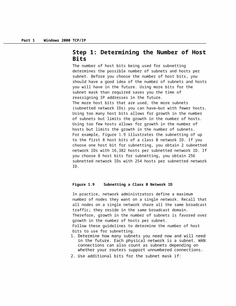
Step 1: Determining the Number of Host BitsThe number of host bits being used for subnetting determines the possible number of subnets and hosts per subnet. Before you choose the number of host bits, you should have a good idea of the number of subnets and hosts you will have in the future. Using more bits for the subnet mask than required saves you the time of reassigning IP addresses in the future.The more host bits that are used, the more subnets (subnetted network IDs) you can have—but with fewer hosts. Using too many host bits allows for growth in the number of subnets but limits the growth in the number of hosts. Using too few hosts allows for growth in the number of hosts but limits the growth in the number of subnets. For example, Figure 1.9 illustrates the subnetting of up to the first 8 host bits of a class B network ID. If you choose one host bit for subnetting, you obtain 2 subnetted network IDs with 16,382 hosts per subnetted network ID. If you choose 8 host bits for subnetting, you obtain 256 subnetted network IDs with 254 hosts per subnetted network ID.

Chapter 1 Introduction to TCP/IP 23
Figure 1.9 Subnetting a Class B Network ID
In practice, network administrators define a maximum number of nodes they want on a single network. Recall that all nodes on a single network share all the same broadcast traffic; they reside in the same broadcast domain. Therefore, growth in the number of subnets is favored over growth in the number of hosts per subnet.Follow these guidelines to determine the number of host bits to use for subnetting.1. Determine how many subnets you need now and will need in the future. Each
physical network is a subnet. WAN connections can also count as subnets depending on whether your routers support unnumbered connections.
2. Use additional bits for the subnet mask if:· You will never require as many hosts per subnet as allowed by the
remaining bits.· The number of subnets will increase in the future, requiring additional host
bits.
To determine the desired subnetting scheme, start with an existing network ID to be subnetted. The network ID to be subnetted can be a class-based network ID, a subnetted network ID, or a supernet. The existing network ID contains a series of network ID bits that are fixed and a series of host ID bits that are variable. Based on your requirements for the number of subnets and the number of hosts per subnet, choose a specific number of host bits to be used for the subnetting.Table 1.16 shows the subnetting of a class A network ID. Based on a required number of subnets, and a maximum number of hosts per subnet, a subnetting scheme can be chosen.Table 1.16 Subnetting a Class A Network ID
Required Number of Subnets
Number of Subnet Bits Subnet Mask
Number of Hosts per Subnet
1-2 1 255.128.0.0 or /9 8,388,6063-4 2 255.192.0.0 or /10 4,194,3025-8 3 255.224.0.0 or /11 2,097,1509-16 4 255.240.0.0 or /12 1,048,57417-32 5 255.248.0.0 or /13 524,28633-64 6 255.252.0.0 or /14 262,14265-128 7 255.254.0.0 or /15 131,070129-256 8 255.255.0.0 or /16 65,534257-512 9 255.255.128.0 or /17 32,766513-1,024 10 255.255.192.0 or /18 16,3821,025-2,048 11 255.255.224.0 or /19 8,190

Part 1 Windows 2000 TCP/IP
2,049-4,096 12 255.255.240.0 or /20 4,0944,097-8,192 13 255.255.248.0 or /21 2,0468,193-16,384 14 255.255.252.0 or /22 1,02216,385-32,768 15 255.255.254.0 or /23 51032,769-65,536 16 255.255.255.0 or /24 25465,537-131,072 17 255.255.255.128 or /25 126131,073-262,144 18 255.255.255.192 or /26 62262,145-524,288 19 255.255.255.224 or /27 30524,289-1,048,576 20 255.255.255.240 or /28 141,048,577-2,097,152 21 255.255.255.248 or /29 62,097,153-4,194,304 22 255.255.255.252 or /30 2
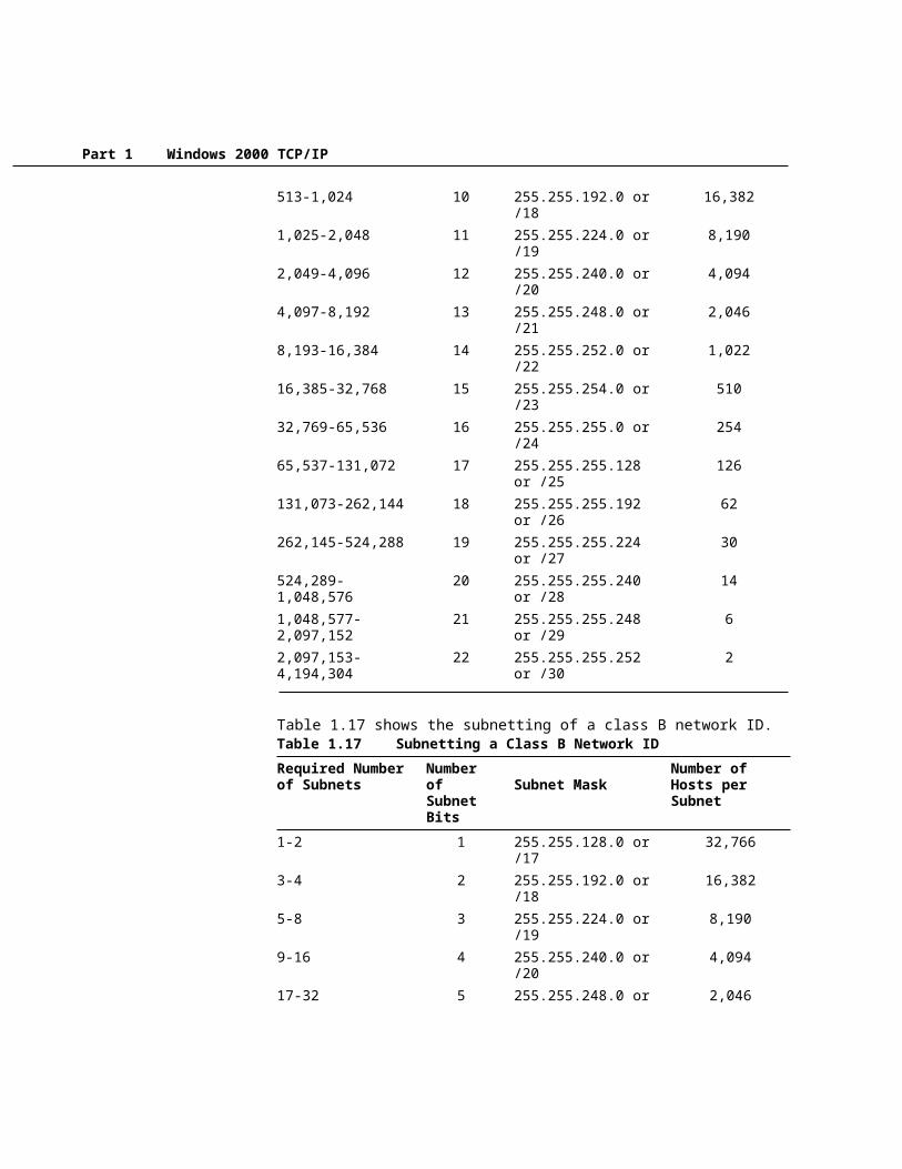
Table 1.17 shows the subnetting of a class B network ID.Table 1.17 Subnetting a Class B Network ID
Required Number of Subnets
Number of Subnet Bits Subnet Mask
Number of Hosts per Subnet
1-2 1 255.255.128.0 or /17 32,7663-4 2 255.255.192.0 or /18 16,3825-8 3 255.255.224.0 or /19 8,1909-16 4 255.255.240.0 or /20 4,09417-32 5 255.255.248.0 or /21 2,04633-64 6 255.255.252.0 or /22 1,02265-128 7 255.255.254.0 or /23 510129-256 8 255.255.255.0 or /24 254257-512 9 255.255.255.128 or /25 126513-1,024 10 255.255.255.192 or /26 621,025-2,048 11 255.255.255.224 or /27 302,049-4,096 12 255.255.255.240 or /28 144,097-8,192 13 255.255.255.248 or /29 68,193-16,384 14 255.255.255.252 or /30 2
Table 1.18 shows the subnetting of a class C network ID.Table 1.18 Subnetting a Class C Network ID
Required Number of Subnets
Number of Subnet Bits Subnet Mask
Number of Hosts per Subnet
1-2 1 255.255.255.128 or /25 1263-4 2 255.255.255.192 or /26 62

Chapter 1 Introduction to TCP/IP 25
5-8 3 255.255.255.224 or /27 309-16 4 255.255.255.240 or /28 14
17-32 5 255.255.255.248 or /29 633-64 6 255.255.255.252 or /30 2
Step 2: Enumerating Subnetted Network IDsBased on the number of host bits you use for your subnetting, you must list the new subnetted network IDs. There are two main approaches:· Binary—List all possible combinations of the host bits chosen for subnetting
and convert each combination to dotted decimal notation.· Decimal—Add a calculated increment value to each successive subnetted
network ID and convert to dotted decimal notation.
Either method produces the same result: the enumerated list of subnetted network IDs.
There are a variety of documented shortcut techniques for subnetting. However, they only work under a specific set of constraints (for example, only up to 8 bits of a class-based network ID). The following methods described are designed to work for any subnetting situation (class-based, more than 8 bits, supernetting, variable length subnetting).
· To create the enumerated list of subnetted network IDs using the binary method1. Based on n, the number of host bits chosen for subnetting, create a three-
column table with 2n entries. The first column is the subnet number (starting with 1), the second column is the binary representation of the subnetted network ID, and the third column is the dotted decimal representation of the subnetted network ID.For each binary representation, the bits of the network ID being subnetted are fixed to their appropriate values and the remaining host bits are set to all 0’s. The host bits chosen for subnetting vary.
2. In the first table entry, set the subnet bits to all 0’s and convert to dotted decimal notation. The original network ID is subnetted with its new subnet mask.
3. In the next table entry, increase the value within the subnet bits.4. Convert the binary result to dotted decimal notation.5. Repeat steps 3 and 4 until the table is complete.
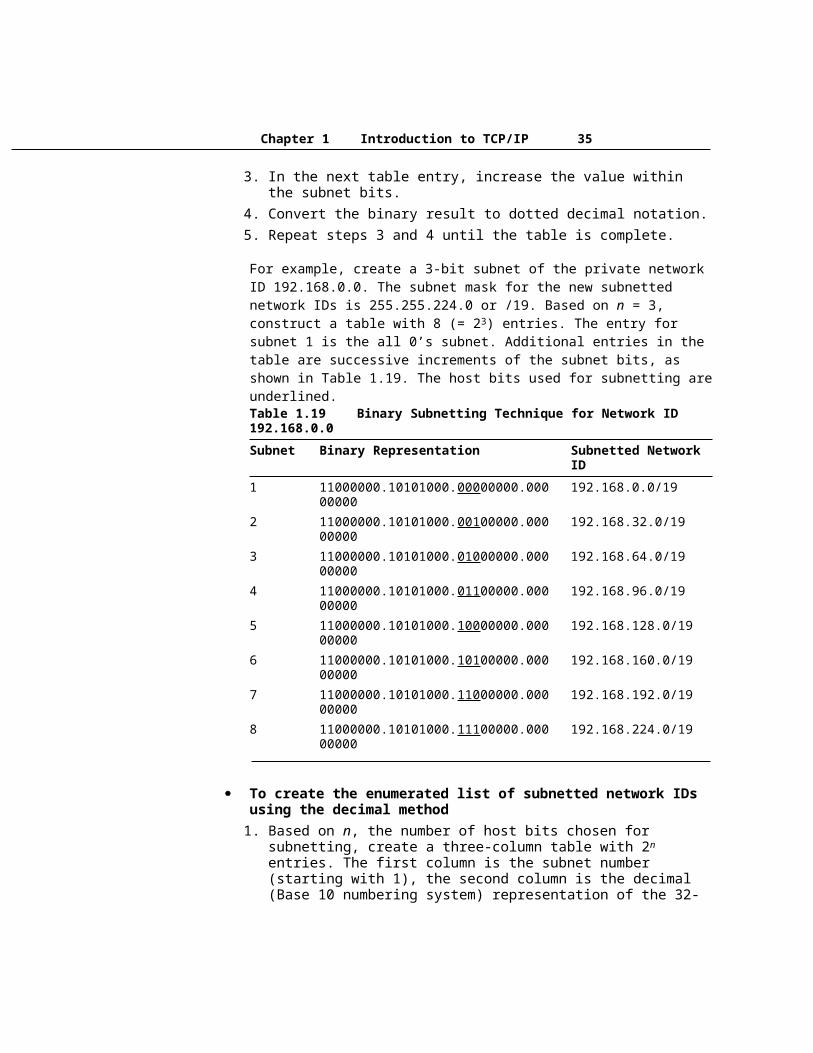
For example, create a 3-bit subnet of the private network ID 192.168.0.0. The subnet mask for the new subnetted network IDs is 255.255.224.0 or /19. Based on n = 3,
Note

Part 1 Windows 2000 TCP/IP
construct a table with 8 (= 23) entries. The entry for subnet 1 is the all 0’s subnet. Additional entries in the table are successive increments of the subnet bits, as shown in Table 1.19. The host bits used for subnetting are underlined.Table 1.19 Binary Subnetting Technique for Network ID 192.168.0.0
Subnet Binary Representation Subnetted Network ID
1 11000000.10101000.00000000.00000000 192.168.0.0/192 11000000.10101000.00100000.00000000 192.168.32.0/193 11000000.10101000.01000000.00000000 192.168.64.0/194 11000000.10101000.01100000.00000000 192.168.96.0/195 11000000.10101000.10000000.00000000 192.168.128.0/196 11000000.10101000.10100000.00000000 192.168.160.0/197 11000000.10101000.11000000.00000000 192.168.192.0/198 11000000.10101000.11100000.00000000 192.168.224.0/19
· To create the enumerated list of subnetted network IDs using the decimal method1. Based on n, the number of host bits chosen for subnetting, create a three-
column table with 2n entries. The first column is the subnet number (starting with 1), the second column is the decimal (Base 10 numbering system) representation of the 32-bit subnetted network ID, and the third column is the dotted decimal representation of the subnetted network ID.
2. Convert the network ID (w.x.y.z) being subnetted from dotted decimal notation to N, a decimal representation of the 32-bit network ID:N = w*16777216 + x*65536 + y*256 + z
3. Compute the increment value I based on h, the number of host bits remaining:I = 2h
4. In the first table entry, the decimal representation of the subnetted network ID is N and the subnetted network ID is w.x.y.z with its new subnet mask.
5. In the next table entry, add I to the previous table entry’s decimal representation.
6. Convert the decimal representation of the subnetted network ID to dotted decimal notation (W.X.Y.Z) through the following formula (where s is the decimal representation of the subnetted network ID):W = INT(s/16777216)X = INT((s mod(16777216))/65536)Y = INT((s mod(65536))/256)Z = s mod(256)

Chapter 1 Introduction to TCP/IP 27
INT( ) denotes integer division, mod( ) denotes the modulus, the remainder upon division.
7. Repeat steps 5 and 6 until the table is complete.For example, create a 3-bit subnet of the private network ID 192.168.0.0. Based on n = 3, construct a table with 8 entries. The entry for subnet 1 is the all 0’s subnet. N, the decimal representation of 192.168.0.0, is 3232235520, the result of 192*16777216 + 168*65536. Because there are 13 host bits remaining, the increment I is 213 = 8192. Additional entries in the table are successive increments of 8192 as shown in Table 1.20.Table 1.20 Decimal Subnetting Technique for Network ID 192.168.0.0
Subnet Decimal Representation Subnetted Network ID
1 3232235520 192.168.0.0/192 3232243712 192.168.32.0/193 3232251904 192.168.64.0/194 3232260096 192.168.96.0/195 3232268288 192.168.128.0/196 3232276480 192.168.160.0/197 3232284672 192.168.192.0/198 3232292864 192.168.224.0/19
RFC 950 forbade the use of the subnetted network IDs where the bits being used for subnetting are set to all 0’s (the all-zeros subnet) and all 1’s (the all-ones subnet). The all-zeros subnet caused problems for early routing protocols and the all-ones subnet conflicts with a special broadcast address called the all-subnets directed broadcast address. However, RFC 1812 now permits the use of the all-zeros and all-ones subnets in a CIDR-compliant environment. CIDR-compliant environments use modern routing protocols that do not have a problem with the all-zeros subnet and the all-subnets directed broadcast is no longer relevant.The all-zeros and all-ones subnets may cause problems for hosts or routers operating in a classful mode. Before you use the all-zeros and all-ones subnets, verify that they are supported by your hosts and routers. Windows 2000 and Windows NT support the use of the all-zeros and all-ones subnets.
Step 3: Enumerating IP Addresses for Each Subnetted Network IDBased on the enumeration of the subnetted network IDs, you must now list the valid IP addresses for new subnetted network IDs. To list each IP address individually would be too tedious. Instead, enumerate the IP addresses for each subnetted
Note

Part 1 Windows 2000 TCP/IP
network ID by defining the range of IP addresses (the first and the last) for each subnetted network ID. There are two main approaches:· Binary—Write down the first and last IP address for each subnetted network
ID and convert to dotted decimal notation.· Decimal—Add values incrementally, corresponding to the first and last IP
addresses for each subnetted network ID and convert to dotted decimal notation.
Either method produces the same result: the range of IP addresses for each subnetted network ID.
· To create the range of IP addresses using the binary method1. Based on n, the number of host bits chosen for subnetting, create a three-
column table with 2n entries. The first column is the subnet number (starting with 1), the second column is the binary representation of the first and last IP address for the subnetted network ID, and the third column is the dotted decimal representation of the first and last IP address of the subnetted network ID. Alternately, add two columns to the previous table used for enumerating the subnetted network IDs.
2. For each binary representation, the first IP address is the address in which all the host bits are set to 0 except for the last host bit. The last IP address is the address in which all the host bits are set to 1 except for the last host bit.
3. Convert the binary representation to dotted decimal notation.4. Repeat steps 2 and 3 until the table is complete.
For example, the range of IP addresses for the 3 bit subnetting of 192.168.0.0 is shown in Table 1.21. The bits used for subnetting are underlined.Table 1.21 Binary Enumeration of IP Addresses
Subnet Binary Representation Range of IP Addresses
1 11000000.10101000.00000000.00000001 -11000000.10101000.00011111.11111110
192.168.0.1 - 192.168.31.254
2 11000000.10101000.00100000.00000001 -11000000.10101000.00111111.11111110
192.168.32.1 - 192.168.63.254
3 11000000.10101000.01000000.00000001 - 11000000.10101000.01011111.11111110
192.168.64.1 - 192.168.95.254
4 11000000.10101000.01100000.00000001 -11000000.10101000.01111111.11111110
192.168.96.1 - 192.168.127.254
5 11000000.10101000.10000000.00000001 - 11000000.10101000.10011111.11111110
192.168.128.1 - 192.168.159.254
6 11000000.10101000.10100000.00000001 - 11000000.10101000.10111111.11111110
192.168.160.1 - 192.168.191.254
7 11000000.10101000.11000000.00000001 -11000000.10101000.11011111.11111110
192.168.192.1 - 192.168.223.254

Chapter 1 Introduction to TCP/IP 29
8 11000000.10101000.11100000.00000001 - 11000000.10101000.11111111.11111110
192.168.224.1 - 192.168.255.254
· To create the range of IP addresses using the decimal method1. Based on n, the number of host bits chosen for subnetting, create a three-
column table with 2n entries. The first column is the subnet number (starting with 1), the second column is the decimal representation of the first and last IP address for the subnetted network ID, and the third column is the dotted decimal representation of the first and last IP address of the subnetted network ID. Alternately, add two columns to the previous table used for enumerating the subnetted network IDs.
2. Compute the increment value J based on h, the number of host bits remaining:J = 2h - 2
3. For each decimal representation, the first IP address is N + 1 where N is the decimal representation of the subnetted network ID. The last IP address is N + J.
4. Convert the decimal representation of the first and last IP addresses to dotted decimal notation (W.X.Y.Z) through the following formula (where s is the decimal representation of the first or last IP address):W = INT(s/16777216)X = INT((s mod(16777216))/65536)Y = INT((s mod(65536))/256)Z = s mod(256)INT( ) denotes integer division, mod( ) denotes the modulus, the remainder upon division.
5. Repeat steps 3 and 4 until the table is complete.
For example, the range of IP addresses for the 3-bit subnetting of 192.168.0.0 is shown in Table 1.22. The increment J is 213 - 2 = 8190.Table 1.22 Decimal Enumeration of IP Addresses
Subnet Decimal Representation Range of IP Addresses
1 3232235521 - 3232243710 192.168.0.1 - 192.168.31.254
2 3232243713 - 3232251902 192.168.32.1 - 192.168.63.254
3 3232251905 - 3232260094 192.168.64.1 - 192.168.95.254
4 3232260097 - 3232268286 192.168.96.1 - 192.168.127.254
5 3232268289 - 3232276478 192.168.128.1 -
Part 1 Windows 2000 TCP/IP
192.168.159.2546 3232276481 - 3232284670 192.168.160.1 -
192.168.191.2547 3232284673 - 3232292862 192.168.192.1 -
192.168.223.2548 3232292865 - 3232301054 192.168.224.1 -
192.168.255.254
Variable Length SubnettingOne of the original uses for subnetting was to subdivide a class-based network ID into a series of equal-sized subnets. For example, a 4-bit subnetting of a class B network ID produced 16 equal-sized subnets (using the all-ones and all-zeros subnets). However, subnetting is a general method of utilizing host bits to express subnets and does not require equal-sized subnets.Subnets of different size can exist within a class-based network ID. This is well-suited to real-world environments, where networks of an organization contain different numbers of hosts, and different-sized subnets are needed to minimize the wasting of IP addresses. The creation and deployment of various-sized subnets of a network ID is known as variable length subnetting and uses variable length subnet masks (VLSM).Variable length subnetting is a technique of allocating subnetted network IDs that use subnet masks of different sizes. However, all subnetted network IDs are unique and can be distinguished from each other by their corresponding subnet mask.The mechanics of variable length subnetting are essentially that of performing subnetting on a previously subnetted network ID. When subnetting, the network ID bits are fixed and a certain number of host bits are chosen to express subnets. With variable length subnetting, the network ID being subnetted has already been subnetted.For example, given the class-based network ID of 135.41.0.0/16, a required configuration is one subnet with up to 32,000 hosts, 15 subnets with up to 2,000 hosts, and eight subnets with up to 250 hosts.One Subnet with up to 32,000 HostsTo achieve a requirement of one subnet with approximately 32,000 hosts, a 1-bit subnetting of the class-based network ID of 135.41.0.0 is done, producing 2 subnets, 135.41.0.0/17 and 135.41.128.0/17. This subnetting allows up to 32,766 hosts per subnet. 135.41.0.0/17 is chosen as the network ID, which fulfills the requirement.Table 1.23 shows one subnet with up to 32,766 hosts per subnet.Table 1.23 One Subnet with up to 32,766 Hosts
Subnet Number Network ID (Dotted Decimal) Network ID (Network Prefix)
1 135.41.0.0, 255.255.128.0 135.41.0.0/17

Chapter 1 Introduction to TCP/IP 31
Fifteen Subnets with up to 2,000 HostsTo achieve a requirement of 15 subnets with approximately 2,000 hosts, a 4-bit subnetting of the subnetted network ID of 135.41.128.0/17 is done. This produces 16 subnets (135.41.128.0/21, 135.41.136.0/21 . . . 135.41.240.0/21, 135.41.248.0/21), allowing up to 2,046 hosts per subnet. The first 15 subnetted network IDs (135.41.128.0/21 to 135.41.240.0/21) are chosen as the network IDs, which fulfills the requirement.Table 1.24 illustrates 15 subnets with up to 2,046 hosts per subnet.Table 1.24 Fifteen Subnets with up to 2,046 Hosts
Subnet Number
Network ID (Dotted Decimal) Network ID (Network Prefix)
1 135.41.128.0, 255.255.248.0 135.41.128.0/212 135.41.136.0, 255.255.248.0 135.41.136.0/213 135.41.144.0, 255.255.248.0 135.41.144.0/21
(continued)Table 1.24 Fifteen Subnets with up to 2,046 Hosts (continued)
Subnet Number
Network ID (Dotted Decimal) Network ID (Network Prefix)
4 135.41.152.0, 255.255.248.0 135.41.152.0/215 135.41.160.0, 255.255.248.0 135.41.160.0/216 135.41.168.0, 255.255.248.0 135.41.168.0/217 135.41.176.0, 255.255.248.0 135.41.176.0/218 135.41.184.0, 255.255.248.0 135.41.184.0/219 135.41.192.0, 255.255.248.0 135.41.192.0/2110 135.41.200.0, 255.255.248.0 135.41.200.0/2111 135.41.208.0, 255.255.248.0 135.41.208.0/2112 135.41.216.0, 255.255.248.0 135.41.216.0/2113 135.41.224.0, 255.255.248.0 135.41.224.0/2114 135.41.232.0, 255.255.248.0 135.41.232.0/2115 135.41.240.0, 255.255.248.0 135.41.240.0/21
Eight Subnets with up to 250 HostsTo achieve a requirement of eight subnets with up to 250 hosts, a 3-bit subnetting of subnetted network ID of 135.41.248.0/21 is done, producing eight subnets (135.41.248.0/24, 135.41.249.0/24 . . . 135.41.254.0/24, 135.41.255.0/24) and allowing up to 254 hosts per subnet. All 8 subnetted network IDs (135.41.248.0/24 to 135.41.255.0/24) are chosen as the network IDs, which fulfills the requirement.Table 1.25 illustrates eight subnets with 254 hosts per subnet.
Part 1 Windows 2000 TCP/IP
Table 1.25 Eight subnets with up to 254 Hosts
Subnet Number Network ID (Dotted Decimal) Network ID (Network Prefix)
1 135.41.248.0, 255.255.255.0 135.41.248.0/242 135.41.249.0, 255.255.255.0 135.41.249.0/243 135.41.250.0, 255.255.255.0 135.41.250.0/244 135.41.251.0, 255.255.255.0 135.41.251.0/245 135.41.252.0, 255.255.255.0 135.41.252.0/246 135.41.253.0, 255.255.255.0 135.41.253.0/247 135.41.254.0, 255.255.255.0 135.41.254.0/248 135.41.255.0, 255.255.255.0 135.41.255.0/24
The variable length subnetting of 135.41.0.0/16 is shown graphically in Figure 1.10.
Figure 1.10 Variable Length Subnetting of 135.41.0.0/16
In dynamic routing environments, variable length subnetting can only be deployed where the subnet mask is advertised along with the network ID. Routing Information Protocol (RIP) for IP version 1 does not support variable length subnetting. RIP for IP version 2, Open Shortest Path First (OSPF), and Border Gateway Protocol version 4 (BGPv4) all support variable length subnetting.
Supernetting and Classless Interdomain RoutingWith the recent growth of the Internet, it became clear to the Internet authorities that the class B network IDs would soon be depleted. For most organizations, a class C network ID does not contain enough host IDs and a class B network ID has enough bits to provide a flexible subnetting scheme within the organization.The Internet authorities devised a new method of assigning network IDs to prevent the depletion of class B network IDs. Rather than assigning a class B network ID, InterNIC assigns a range of class C network IDs that contain enough network and host IDs for the organization’s needs. This is known as supernetting. For example, rather than allocating a class B network ID to an organization that has up to 2,000 hosts, the InterNIC allocates a range of eight class C network IDs. Each class C network ID accommodates 254 hosts, for a total of 2,032 host IDs.Although this technique helps conserve class B network IDs, it creates a new problem. Using conventional routing techniques, the routers on the Internet now must have eight class C network ID entries in their routing tables to route IP packets to the organization. To prevent Internet routers from becoming overwhelmed with routes, a technique called Classless Interdomain Routing (CIDR) is used to collapse
Note

Chapter 1 Introduction to TCP/IP 33
multiple network ID entries into a single entry corresponding to all of the class C network IDs allocated to that organization.Conceptually, CIDR creates the routing table entry: [Starting Network ID, count], where Starting Network ID is the first class C network ID and the count is the number of class C network IDs allocated. In practice, a supernetted subnet mask is used to convey the same information. To express the situation where eight class C network IDs are allocated starting with network ID 220.78.168.0:Starting Network ID 220.78.168.0 11011100 01001110 10101000 00000000Ending Network ID 220.78.175.0 11011100 01001110 10101111 00000000
Note that the first 21 bits (underlined) of all the above Class C network IDs are the same. The last three bits of the third octet vary from 000 to 111. The CIDR entry in the routing tables of the Internet routers becomes:Network ID Subnet Mask Subnet Mask (binary)
220.78.168.0 255.255.248.0 11111111 11111111 11111000 0000000
In network prefix or CIDR notation, the CIDR entry is 220.78.168.0/21.A block of addresses using CIDR is known as a CIDR block.
Because subnet masks are used to express the count, class-based network IDs must be allocated in groups corresponding to powers of 2.
In order to support CIDR, routers must be able to exchange routing information in the form of [Network ID, Network Mask] pairs. RIP for IP version 2, OSPF and BGPv4 are routing protocols that support CIDR. RIP for IP version 1 does not support CIDR.
Address Space PerspectiveThe use of CIDR to allocate addresses promotes a new perspective on IP network IDs. In the above example, the CIDR block [220.78.168.0, 255.255.248.0] can be thought of in two ways:· A block of eight class C network IDs.· An address space in which 21 bits are fixed and 11 bits are assignable.
In the latter perspective, IP network IDs lose their class-based heritage and become separate IP address spaces, subsets of the original IP address space defined by the 32-bit IP address. Each IP network ID (class-based, subnetted, CIDR block), is an address space in which certain bits are fixed (the network ID bits) and certain bits are variable (the host bits). The host bits are assignable as host IDs or, using subnetting techniques, can be used in whatever manner best suits the needs of the organization.
Public and Private AddressesIf your intranet is not connected to the Internet, any IP addressing can be deployed. If direct (routed) or indirect (proxy or translator) connectivity to the Internet is desired, there are two types of addresses employed on the Internet, public addresses and private addresses.
Note

Part 1 Windows 2000 TCP/IP
Public AddressesPublic addresses are assigned by InterNIC and consist of class-based network IDs or blocks of CIDR-based addresses (called CIDR blocks) that are guaranteed to be globally unique to the Internet.When the public addresses are assigned, routes are programmed into the routers of the Internet so that traffic to the assigned public addresses can reach their locations. Traffic to destination public addresses are reachable on the Internet.For example, when an organization is assigned a CIDR block in the form of a network ID and subnet mask, that [network ID, subnet mask] pair also exists as a route in the routers of the Internet. IP packets destined to an address within the CIDR block are routed to the proper destination.
Illegal AddressesPrivate intranets that have no intent on connecting to the Internet can choose any addresses they want, even public addresses that have been assigned by the InterNIC. If an organization later decides to connect to the Internet, its current address scheme might include addresses already assigned by the InterNIC to other organizations. These addresses would be duplicate or conflicting addresses and are known as illegal addresses. Connectivity from illegal addresses to Internet locations is not possible.For example, a private organization chooses to use 207.46.130.0/24 as its intranet address space. The public address 207.46.130.0/24 has been assigned to the Microsoft corporation and routes exist on the Internet routers to route all packets destined to IP addresses on 207.46.130.0/24 to Microsoft routers. As long as the private organization does not connect to the Internet, there is no problem because the two address spaces are on separate IP internetworks. If the private organization then connected directly to the Internet and continued to use 207.46.130.0/24 as its address space, then any Internet response traffic to locations on the 207.46.130.0/24 network would be routed to Microsoft routers, not to the routers of the private organization.
Private AddressesEach IP node requires an IP address that is globally unique to the IP internetwork. In the case of the Internet, each IP node on a network connected to the Internet requires an IP address that is globally unique to the Internet. As the Internet grew, organizations connecting to the Internet required a public address for each node on their intranets. This requirement placed a huge demand on the pool of available public addresses.When analyzing the addressing needs of organizations, the designers of the Internet noted that for many organizations, most of the hosts on the organization’s intranet did not require direct connectivity to Internet hosts. Those hosts that did require a specific set of Internet services, such as the World Wide Web access and e-mail, typically access the Internet services through Application layer gateways such as proxy servers and e-mail servers. The result is that most organizations only required a small amount of public addresses for those nodes (such as proxies, routers, firewalls, and translators) that were directly connected to the Internet.For the hosts within the organization that do not require direct access to the Internet, IP addresses that do not duplicate already-assigned public addresses are required. To solve this addressing problem, the Internet designers reserved a portion of the IP
Chapter 1 Introduction to TCP/IP 35
address space and named this space the private address space. An IP address in the private address space is never assigned as a public address. IP addresses within the private address space are known as private addresses. Because the public and private address spaces do not overlap, private addresses never duplicate public addresses.The private address space specified in RFC 1918 is defined by the following three address blocks:· 10.0.0.0/8
The 10.0.0.0/8 private network is a class A network ID that allows the following range of valid IP addresses: 10.0.0.1 to 10.255.255.254. The 10.0.0.0/8 private network has 24 host bits that can be used for any subnetting scheme within the private organization.
· 172.16.0.0/12The 172.16.0.0/12 private network can be interpreted either as a block of 16 class B network IDs or as a 20-bit assignable address space (20 host bits) that can be used for any subnetting scheme within the private organization. The 172.16.0.0/12 private network allows the following range of valid IP addresses: 172.16.0.1 to 172.31.255.254.
· 192.168.0.0/16The 192.168.0.0/16 private network can be interpreted either as a block of 256 class C network IDs or as a 16-bit assignable address space (16 host bits) that can be used for any subnetting scheme within the private organization. The 192.168.0.0/16 private network allows the following range of valid IP addresses: 192.168.0.1 to 192.168.255.254.
The result of many organizations using private addresses is that the private address space is re-used, helping to prevent the depletion of public addresses.Because the IP addresses in the private address space will never be assigned by the InterNIC as public addresses, there will never exist routes in the Internet routers for private addresses. Private addresses are not reachable on the Internet. Therefore, Internet traffic from a host that has a private address must either send its requests to an Application layer gateway (such as a proxy server), which has a valid public address, or have its private address translated into a valid public address by a network address translator (NAT) before it is sent on the Internet. For more information about NAT, see “Unicast IP Routing” in the Microsoft® Windows® 2000 Server Resource Kit Internetworking Guide.
Name ResolutionWhile IP is designed to work with the 32-bit IP addresses of the source and the destination hosts, computers users are much better at using and remembering names than IP addresses.If a name is used as an alias for the IP address, a mechanism must exist for assigning that name to the appropriate IP node to ensure its uniqueness and resolving it to its IP address.

Part 1 Windows 2000 TCP/IP
In this section, the mechanisms used for assigning and resolving host names (which are used by Windows Sockets applications), and NetBIOS names (which are used by NetBIOS applications) are discussed.
Host Name ResolutionA host name is an alias assigned to an IP node to identify it as a TCP/IP host. The host name can be up to 255 characters long and can contain alphabetic and numeric characters and the “-” and “.” characters. Multiple host names can be assigned to the same host. For Windows 2000–based computers, the host name does not have to match the Windows 2000 computer name.Windows Sockets applications, such as Microsoft® Internet Explorer and the FTP utility, can use one of two values for the destination to be connected: the IP address or a host name. When the IP address is specified, name resolution is not needed. When a host name is specified, the host name must be resolved to an IP address before IP-based communication with the desired resource can begin.Host names can take various forms. The two most common forms are a nickname and a domain name. A nickname is an alias to an IP address that individual people can assign and use. A domain name is a structured name that follows Internet conventions.
Domain NamesTo facilitate different organizations and their desires to have scaleable, customizable naming scheme in which to operate, the InterNIC has created and maintains a hierarchical namespace called the Domain Name System (DNS). DNS is a naming scheme that looks similar to the directory structure for files on a disk. However, instead of tracing a file from the root directory through subdirectories to its final location and its file name, a host name is traced from its final location through its parent domains back up to the root. The unique name of the host, representing its position in the hierarchy, is called its Fully Qualified Domain Name (FQDN). The top-level domain namespace is shown in Figure 1.11 with example second-level and subdomains.
Figure 1.11 Domain Name System
The domain namespace consists of:· The root domain, representing the root of the namespace and indicated with a
“” (null).· Top-level domains, those directly below the root, indicating a type of
organization. On the Internet, the InterNIC is responsible for the maintenance of top-level domain names. Table 1.26 has a partial list of the Internet’s top-level domain names.

Chapter 1 Introduction to TCP/IP 37
Table 1.26 Internet Top-Level Domain Names
Domain Name Meaning
COM Commercial organizationEDU Educational institutionGOV Government institutionMIL Military groupNET Major network support centerORG Organization other than those aboveINT International organization<country/region code>
Each country/region (geographic scheme)
· Second-level domains, below the top level domains, identifying a specific organization within its top-level domain. On the Internet, the InterNIC is responsible for the maintenance of second-level domain names and ensuring their uniqueness.
· Subdomains of the organization, below the second-level domain. The individual organization is responsible for the creation and maintenance of subdomains.
For example, for the FQDN ftpsrv.wcoast.reskit.com:· The trailing period (.) denotes that this is an FQDN with the name relative to
the root of the domain namespace. The trailing period is usually not required for FQDNs and if it is missing it is assumed to be present.
· com is the top-level domain, indicating a commercial organization.· reskit is the second-level domain, indicating the Windows 2000 Resource Kit
organization.· wcoast is a subdomain of reskit.com indicating the West Coast division of the
Windows 2000 Resource Kit organization.· ftpsrv is the name of the FTP server in the West Coast division.
Domain names are not case sensitive.Organizations not connected to the Internet can implement whatever top and second-level domain names they want. However, typical implementations do adhere to the InterNIC specification so that eventual participation in the Internet will not require a renaming process.
Host Name Resolution Using a Hosts FileOne common way to resolve a host name to an IP address is to use a locally stored database file that contains IP-address-to-host-name mappings. On most UNIX

Part 1 Windows 2000 TCP/IP
systems, this file is /etc/hosts. On Windows 2000 systems, it is the Hosts file in the \%SystemRoot%\system32\drivers\etc directory.Following is an example of the contents of the Hosts file:## Table of IP addresses and host names#127.0.0.1 localhost139.41.34.1 router167.91.45.121 server1.central.slate.com s1

Chapter 1 Introduction to TCP/IP 39
Within the Hosts file:· Multiple host names can be assigned to the same IP address. Note that the
server at the IP address 167.91.45.121 can be referred to by its FQDN (server1.central.slate.com) or a nickname (s1). This allows the user at this computer to refer to this server using the nickname s1 rather than typing the entire FQDN.
· Entries can be case sensitive depending on the platform. Entries in the Hosts file for UNIX computers are case sensitive. Entries in the Hosts file for Windows 2000 and Windows NT–based computers are not case sensitive.
The advantage of using a Hosts file is that it is customizable for the user. Each user can create whatever entries they want, including easy-to-remember nicknames for frequently accessed resources. However, the individual maintenance of the Hosts file does not scale well to storing large numbers of FQDN mappings.
Host Name Resolution Using a DNS ServerTo make host name resolution scalable and centrally manageable, IP address mappings for FQDNs are stored on DNS servers, computers that stores FQDN-to-IP-address mappings. To enable the querying of a DNS server by a host computer, a component called the DNS resolver is enabled and configured with the IP address of the DNS server. The DNS resolver is a built-in component of TCP/IP protocol stacks supplied with most network operating systems, including Windows 2000.When a Windows Sockets application is given an FQDN as the destination location, the application calls a Windows Sockets function to resolve the name to an IP address. The request is passed to the DNS resolver component in the TCP/IP protocol. The DNS resolver packages the FQDN request as a DNS Name Query packet and sends it to the DNS server.DNS is a distributed naming system. Rather than storing all the records for the entire namespace on each DNS server, each DNS server only stores the records for a specific portion of the namespace. The DNS server is authoritative for the portion of the namespace that corresponds to records stored on that DNS server. In the case of the Internet, hundreds of DNS servers store various portions of the Internet namespace. To facilitate the resolution of any valid domain name by any DNS server, DNS servers are also configured with pointer records to other DNS servers.The following process outlines what happens when the DNS resolver component on a host sends a DNS query to a DNS server. This process is shown in Figure 1.12 and is simplified so that you can gain a basic understanding of the DNS resolution process.1. The DNS resolver component of the DNS client formats a DNS Name Query
containing the FQDN and sends it to the configured DNS server.2. The DNS server checks the FQDN in the DNS Name Query against locally
stored address records. If a record is found, the IP address corresponding to the requested FQDN is sent back to the client.
3. If the FQDN is not found, the DNS server forwards the request to a DNS server that is authoritative for the FQDN.

Part 1 Windows 2000 TCP/IP
4. The authoritative DNS server returns the reply, containing the resolved IP address, back to the original DNS server.
5. The original DNS server sends the IP address mapping information to the client.
Figure 1.12 Resolving an FQDN Using DNS Servers
To obtain the IP address of a server that is authoritative for the FQDN, DNS servers on the Internet go through an iterative process of querying multiple DNS servers until the authoritative server is found. More details about this iterative process can be found in “Windows 2000 DNS” in this book.
Combining a Local Database File with DNSTCP/IP implementations, including Windows 2000, allow the use of both a local database file and a DNS server to resolve host names. When a user specifies a host name in a TCP/IP command or utility:1. TCP/IP checks the local database file (the Hosts file) for a matching name.2. If a matching name is not found in the local database file, the host name is
packaged as a DNS Name Query and sent to the configured DNS server.
Combining both methods gives the user the ability to have a local database file to resolve personalized nicknames and to use the globally distributed DNS database to resolve FQDNs.
NetBIOS Name ResolutionNetBIOS name resolution is the process of successfully mapping a NetBIOS name to an IP address. A NetBIOS name is a 16-byte address used to identify a NetBIOS resource on the network. A NetBIOS name is either a unique (exclusive) or group (nonexclusive) name. When a NetBIOS process communicates with a specific process on a specific computer, a unique name is used. When a NetBIOS process communicates with multiple processes on multiple computers, a group name is used.The NetBIOS name acts as a session layer application identifier. For example, the NetBIOS Session service operates over TCP port 139. All NetBIOS over TCP/IP session requests are addressed to TCP destination port 139. When identifying a NetBIOS application with which to establish a NetBIOS session, the NetBIOS name is used.An example of a process using a NetBIOS name is the file and print sharing server service on a Windows 2000–based computer. When your computer starts up, the server service registers a unique NetBIOS name based on your computer’s name. The exact name used by the server service is the 15 character computer name plus a 16th character of 0x20. If the computer name is not 15 characters long, it is padded with spaces up to 15 characters long. Other network services also use the computer name to build their NetBIOS names so the 16th character is used to uniquely identify
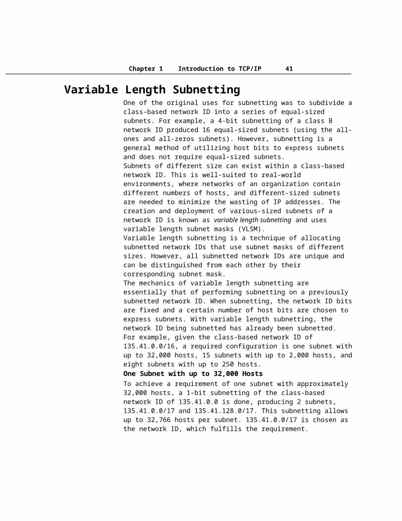
Chapter 1 Introduction to TCP/IP 41
each service, such as the redirector, server, or messenger services. Figure 1.13 shows the NetBIOS names associated with the server, redirector, and messenger services.
Figure 1.13 NetBIOS Names and Services
When you attempt to make a file-sharing connection to a Windows 2000–based computer by name, the server service on the file server you specify corresponds to a specific NetBIOS name. For example, when you attempt to connect to the computer called CORPSERVER, the NetBIOS name corresponding to the server service is “CORPSERVER <20>” (note the padding using the space character). Before a file and print sharing connection can be established, a TCP connection must be created. In order for a TCP connection to be established, the NetBIOS name “CORPSERVER <20>” must be resolved to an IP address.To view the NetBIOS names registered by NetBIOS processes running on a Windows 2000 computer, type nbtstat -n at the Windows 2000 command prompt.
NetBIOS Node TypesThe exact mechanism by which NetBIOS names are resolved to IP addresses depends on the node’s configured NetBIOS Node Type. RFC 1001 define the NetBIOS Node Types, as listed in Table 1.27.Table 1.27 NetBIOS Node Types
Node Type Description
B-node (broadcast)
B-node uses broadcasted NetBIOS Name Queries for name registration and resolution. B-node has two major problems: (1) In a large internetwork, broadcasts can increase the network load, and (2) Routers typically do not forward broadcasts, so only NetBIOS name on the local network can be resolved.
(continued)Table 1.27 NetBIOS Node Types (continued)
Node Type Description
P-node (peer-peer)
P-node uses a NetBIOS name server (NBNS), such as Windows Internet Name Service (WINS), to resolve NetBIOS name. P-node does not use broadcasts; instead, it queries the name server directly. The most significant problem with P-node is that all computers must be configured with the IP address of the NBNS, and if the NBNS is down, computers are not able to communicate even on the local network.
M-node (mixed)
M-node is a combination of B-node and P-node. By default, an M-node functions as a B-node. If it is unable to resolve a name by broadcast, it uses the NBNS of P-node.
H-node (hybrid)
H-node is a combination of P-node and B-node. By default, an H-node functions as a P-node. If it is unable to resolve a name through the NetBIOS name server, it uses a broadcast to resolve the name.

Part 1 Windows 2000 TCP/IP
Windows 2000–based computers are B-node by default and become H-node when configured for a WINS server. Windows 2000 also uses a local database file called Lmhosts to resolve remote NetBIOS names.For more information about WINS, see “Windows Internet Name Service” in this book. For more information about the Lmhosts file, see “LMHOSTS” in this book.
IP RoutingAfter the host name or NetBIOS name is resolved to an IP address, the IP packet must be sent by the sending host to the resolved IP address. Routing is the process of forwarding a packet based on the destination IP address. Routing occurs at a sending TCP/IP host and at an IP router. A router is a device that forwards the packets from one network to another. Routers are also commonly referred to as gateways. In both cases, sending host and router, a decision has to be made about where the packet is forwarded.To make these decisions, the IP layer consults a routing table stored in memory. Routing table entries are created by default when TCP/IP initializes and additional entries are added either manually by a system administrator or automatically through communication with routers.
Direct and Indirect DeliveryForwarded IP packets use at least one of two types of delivery based on whether the IP packet is forwarded to the final destination or whether it is forwarded to an IP router. These two types of delivery are known as direct and indirect delivery.Direct delivery occurs when the IP node (either the sending node or an IP router) forwards a packet to the final destination on a directly attached network. The IP node encapsulates the IP datagram in a frame format for the Network Interface layer (such as Ethernet or Token Ring) addressed to the destination’s physical address.Indirect delivery occurs when the IP node (either the sending node or an IP router) forwards a packet to an intermediate node (an IP router) because the final destination is not on a directly attached network. The IP node encapsulates the IP datagram in a frame format, addressed to the IP router’s physical address, for the Network Interface layer (such as Ethernet or Token Ring).IP routing is a combination of direct and indirect deliveries.In Figure 1.14, when sending packets to node B, node A performs a direct delivery. When sending packets to node C, node A performs an indirect delivery to Router 1. Router 1 performs an indirect delivery to Router 2. Router 2 performs a direct delivery to node C.
Figure 1.14 Direct and Indirect Deliveries
IP Routing TableA routing table is present on all IP nodes. The routing table stores information about IP networks and how they can be reached (either directly or indirectly). Because all

Chapter 1 Introduction to TCP/IP 43
IP nodes perform some form of IP routing, routing tables are not exclusive to IP routers. Any node loading the TCP/IP protocol has a routing table. There are a series of default entries according to the configuration of the node and additional entries can be entered either manually through TCP/IP utilities or dynamically through interaction with routers.When an IP packet is to be forwarded, the routing table is used to determine:1. The forwarding or next-hop IP address:
For a direct delivery, the forwarding IP address is the destination IP address in the IP packet. For an indirect delivery, the forwarding IP address is the IP address of a router.
2. The interface to be used for the forwarding:The interface identifies the physical or logical interface such as a network adapter that is used to forward the packet to either its destination or the next router.
IP Routing Table Entry TypesAn entry in the IP routing table contains the following information in the order presented:Network ID. The network ID or destination corresponding to the route. The network ID can be class-based, subnet, or supernet network ID, or an IP address for a host route.Network Mask. The mask that is used to match a destination IP address to the network ID.Next Hop. The IP address of the next hop.Interface. An indication of which network interface is used to forward the IP packet.Metric. A number used to indicate the cost of the route so the best route among possible multiple routes to the same destination can be selected. A common use of the metric is to indicate the number of hops (routers crossed) to the network ID.Routing table entries can be used to store the following types of routes:Directly Attached Network IDs. Routes for network IDs that are directly attached. For directly attached networks, the Next Hop field can be blank or contain the IP address of the interface on that network.Remote Network IDs. Routes for network IDs that are not directly attached but are available across other routers. For remote networks, the Next Hop field is the IP address of a local router in between the forwarding node and the remote network.Host Routes. A route to a specific IP address. Host routes allow routing to occur on a per-IP address basis. For host routes, the network ID is the IP address of the specified host and the network mask is 255.255.255.255.Default Route. The default route is designed to be used when a more specific network ID or host route is not found. The default route network ID is 0.0.0.0 with the network mask of 0.0.0.0.
Route Determination ProcessTo determine which routing table entry is used for the forwarding decision, IP uses the following process:
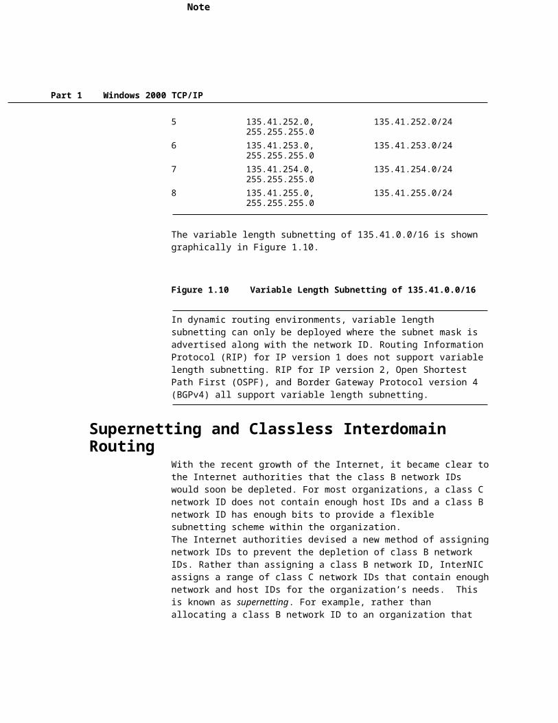
Part 1 Windows 2000 TCP/IP
· For each entry in a routing table, perform a bit-wise logical AND between the destination IP address and the network mask. Compare the result with the network ID of the entry for a match.
· The list of matching routes is compiled. The route that has the longest match (the route that matched the most amount of bits with the destination IP address) is chosen. The longest matching route is the most specific route to the destination IP address. If multiple entries with the longest match are found (multiple routes to the same network ID, for example), the router uses the lowest metric to select the best route. If multiple entries exist that are the longest match and the lowest metric, the router is free to choose which routing table entry to use.
The end result of the route determination process is the choice of a single route in the routing table. The route chosen yields a forwarding IP address (the next hop IP address) and an interface (the port). If the route determination process fails to find a route, IP declares a routing error. For the sending host, an IP routing error is internally indicated to the upper layer protocol such as TCP or UDP. For a router, an ICMP Destination Unreachable-Host Unreachable message is sent to the source host.
Example Routing Table for Windows 2000Table 1.28 shows the default routing table for a Windows 2000–based host (not a router). The host has a single network adapter and has the IP address 157.55.27.90, subnet mask 255.255.240.0 (/20), and default gateway of 157.55.16.1.
Table 1.28 Windows 2000 Routing Table
Network Destination Netmask Gateway Interface Metric Purpose
0.0.0.0 0.0.0.0 157.55.16.1 157.55.27.90 1 Default Route127.0.0.0 255.0.0.0 127.0.0.1 127.0.0.1 1 Loopback Network157.55.16.0 255.255.240.0 157.55.27.90 157.55.27.90 1 Directly Attached Network157.55.27.90 255.255.255.255 127.0.0.1 127.0.0.1 1 Local Host157.55.255.255 255.255.255.255 157.55.27.90 157.55.27.90 1 Network Broadcast224.0.0.0 224.0.0.0 157.55.27.90 157.55.27.90 1 Multicast Address255.255.255.255 255.255.255.255 157.55.27.90 157.55.27.90 1 Limited Broadcast
The entry corresponding to the default gateway configuration is a network destination of 0.0.0.0 with a network mask (netmask) of 0.0.0.0. Any destination IP address joined with 0.0.0.0 by a logical AND results in 0.0.0.0. Therefore, for any IP address, the default route produces a match. If the default route is chosen because no better routes were found, the IP packet is forwarded to the IP address in the Gateway column using the interface corresponding to the IP address in the Interface column.The loopback network entry is designed to take any IP address of the form 127.x.y.z and forward it to the special loopback address of 127.0.0.1.
Default Route Loopback Network

Chapter 1 Introduction to TCP/IP 45
The local network entry corresponds to the directly attached network. IP packets destined for the directly attached network are not forwarded to a router but sent directly to the destination. Note that the Gateway and Interface columns match the IP address of the node. This indicates that the packet is sent from the network adapter corresponding to the node’s IP address.The local host entry is a host route (network mask of 255.255.255.255) corresponding to the IP address of the host. All IP datagrams to the IP address of the host are forwarded to the loopback address.The network broadcast entry is a host route (network mask of 255.255.255.255) corresponding to the all-subnets directed broadcast address (all subnets of class B network ID 157.55.0.0). Packets addressed to the all-subnets directed broadcast are sent from the network adapter corresponding to the node’s IP address.The multicast address, with its class D network mask, is used to route any multicast IP packets from the network adapter corresponding to the node’s IP address.The limited broadcast address is a host route (network mask of 255.255.255.255). Packets addressed to the limited broadcast are sent from the network adapter corresponding to the node’s IP address.
To view the IP routing table on a Windows 2000-based computer, type route print at a Windows 2000 command prompt.When determining the forwarding or next-hop IP address from a route in the routing table:· If the gateway address is the same as the interface address, the forwarding IP
address is set to the destination IP address of the IP packet.· If the gateway address is not the same as the interface address, the forwarding
IP address is set to the gateway address.
For example, when traffic is sent to 157.55.16.48, the most specific route is the route for the directly attached network (157.55.16.0/20). The forwarding IP address is set to destination IP address (157.55.16.48) and the interface is the network adapter, which has been assigned the IP address 157.55.27.90.When sending traffic to 157.20.0.79, the most specific route is the default route (0.0.0.0/0). The forwarding IP address is set to the gateway address (157.20.16.1) and the interface is the network adapter, which has been assigned the IP address 157.55.27.90.
Routing ProcessesThe IP routing processes on all nodes involved in the delivery of an IP packet includes: the sending host, the intermediate routers, and the destination host.
IP on the Sending HostWhen a packet is sent by a sending host, the packet is handed from an upper layer protocol (TCP, UDP, or ICMP) to IP. IP on the sending host does the following:1. Sets the Time-to-Live (TTL) value to either a default or application-specified
value. 2. IP checks its routing table for the best route to the destination IP address.
Directly Attached Network Local Host Network Broadcast Multicast AddressLimited Broadcast

Part 1 Windows 2000 TCP/IP
If no route is found, IP indicates a routing error to the upper layer protocol (TCP, UDP, or ICMP).
3. Based on the most specific route, IP determines the forwarding IP address and the interface to be used for forwarding the packet.
4. IP hands the packet, the forwarding IP address, and the interface to Address Resolution Protocol (ARP), and then ARP resolves the forwarding IP address to its media access control (MAC) address and forwards the packet.
IP on the RouterWhen a packet is received at a router, the packet is passed to IP. IP on the router does the following:1. IP verifies the IP header checksum.
If the IP header checksum fails, the IP packet is discarded without notification to the user. This is known as a silent discard.
2. IP verifies whether the destination IP address in the IP datagram corresponds to an IP address assigned to a router interface. If so, the router processes the IP datagram as the destination host (see step 3 in the following “IP on the Destination Host” section).
3. If the destination IP address is not the router, IP decreases the time-to-live (TTL) by 1. If the TTL is 0, the router discards the packet and sends an ICMP Time Expired-TTL Expired message to the sender.
4. If the TTL is 1 or greater, IP updates the TTL field and calculates a new IP header checksum.
5. IP checks its routing table for the best route to the destination IP address in the IP datagram.If no route is found, the router discards the packet and sends an ICMP Destination Unreachable-Network Unreachable message to the sender.
6. Based on the best route found, IP determines the forwarding IP address and the interface to be used for forwarding the packet.
7. IP hands the packet, the forwarding IP address, and the interface to ARP, and then ARP forwards the packet to the appropriate MAC address.
This entire process is repeated at each router in the path between the source and destination host.
IP on the Destination HostWhen a packet is received at the destination host, it is passed up to IP. IP on the destination host does the following:1. IP verifies the IP header checksum.
If the IP header checksum fails, the IP packet is silently discarded.
Chapter 1 Introduction to TCP/IP 47
2. IP verifies that the destination IP address in the IP datagram corresponds to an IP address assigned to the host.If the destination IP address is not assigned to the host, the IP packet is silently discarded.
3. Based on the IP protocol field, IP passes the IP datagram without the IP header to the appropriate upper-level protocol.If the protocol does not exist, ICMP sends a Destination Unreachable-Protocol Unreachable message back to the sender.
4. For TCP and UDP packets, the destination port is checked and the TCP segment or UDP header is processed.If no application exists for the UDP port number, ICMP sends a Destination Unreachable-Port Unreachable message back to the sender. If no application exists for the TCP port number, TCP sends a Connection Reset segment back to the sender.
Static and Dynamic IP RoutersFor IP routing between routers to occur efficiently in the IP internetwork, routers must have explicit knowledge of remote network IDs or be properly configured with a default route. On large IP internetworks, one of the challenges faced by network administrators is how to maintain the routing tables on their IP routers so that IP traffic flow is traveling the best path and is fault tolerant.There are two ways of maintaining routing table entries on IP routers:· Manually—Static IP routers have routing tables that do not change unless
manually changed by a network administrator. Static routing relies on the manual administration of the routing table. Remote network IDs are not discovered by static routers and must be manually configured. Static routers are not fault tolerant. If a static router goes down, neighboring routers do not sense the fault and inform other routers.
· Automatically—Dynamic IP routers have routing tables that change automatically based on the communication of routing information with other routers.Dynamic routing employs the use of routing protocols, such as Routing Information Protocol (RIP) and Open Shortest Path First (OSPF), to dynamically update the routing table through the exchange of routing information between routers. Remote network IDs are discovered by dynamic routers and automatically entered into the routing table. Dynamic routers are fault tolerant. If a dynamic router goes down, the fault is sensed by neighboring routers who propagate the changed routing information to the other routers in the internetwork.

Part 1 Windows 2000 TCP/IP
For more information about routing principles, see “Unicast Routing Overview” in the Windows 2000 Internetworking Guide. For more information about IP routing protocols, see “Unicast IP Routing” in the Windows 2000 Internetworking Guide.
Physical Address ResolutionBased on the destination IP address and the route determination process, IP determines the forwarding IP address and interface to be used to forward the packet. IP then hands the IP packet, the forwarding IP address, and the interface, to ARP.If the forwarding IP address is the same as the destination IP address, then ARP performs a direct delivery. In a direct delivery, the MAC address corresponding to the destination IP address must be resolved.If the forwarding IP address is not the same as the destination IP address, then ARP performs an indirect delivery. The forwarding IP address is the IP address of a router between the current IP node and the final destination. In an indirect delivery, the MAC address corresponding to the IP address of the router must be resolved.To resolve a forwarding IP address to its MAC address, ARP uses the broadcasting facility on shared access networking technologies (such as Ethernet or Token Ring) to send out a broadcasted ARP Request frame. An ARP Reply, containing the MAC address corresponding to the requested forwarding IP address, is sent back to the sender of the ARP Request.
ARP CacheTo keep the number of broadcasted ARP Request frames to a minimum, many TCP/IP protocol stacks incorporate an ARP cache, a table of recently resolved IP addresses and their corresponding MAC addresses. The ARP cache is checked first before sending an ARP Request frame. Each interface has its own ARP cache.Depending on the vendor implementation, the ARP cache can have the following qualities:· ARP cache entries can be dynamic (based on ARP Replies) or static. Static
ARP entries are permanent and are manually added using a TCP/IP utility such as the ARP utility provided with Windows 2000. Static ARP cache entries are used to prevent ARP Requests for commonly-used local IP addresses, such as routers and servers. The problem with static ARP entries is that they have to be manually updated when network interface equipment changes.
· Dynamic ARP cache entries have a time-out value associated with them to remove entries in the cache after a specified period of time. Dynamic ARP cache entries for Windows 2000 TCP/IP are given a maximum time of 10 minutes before being removed.
To view the ARP cache on a Windows 2000–based computer, type arp -a at a Windows 2000 command prompt.

Chapter 1 Introduction to TCP/IP 49
ARP ProcessIP sends information to ARP. ARP receives the IP packet, the forwarding IP address, and the interface to be used to forward the packet. Whether performing a direct or indirect delivery, ARP performs the following process, as displayed in Figure 1.15:1. Based on the interface and the forwarding IP address, ARP consults the
appropriate ARP cache for an entry for the forwarding IP address. If an entry is found, ARP skips to step 6.
2. If the entry is not found, ARP builds an ARP Request frame containing the MAC address of the interface sending the ARP Request, the IP address of the interface sending the ARP Request, and the forwarding IP address. ARP then broadcasts the ARP Request using the appropriate interface.
3. All hosts receive the broadcasted frame and the ARP Request is processed. If the receiving host’s IP address matches the requested IP address (the forwarding IP address), its ARP cache is updated with the address mapping of the sender of the ARP Request.If the receiving host’s IP address does not match the requested IP address, the ARP Request is silently discarded.
4. The receiving host formulates an ARP Reply containing the requested MAC address and sends it directly to the sender of the ARP Request.
5. When the ARP Reply is received by the sender of the ARP Request, it updates its ARP cache with the address mapping. Between the ARP Request and the ARP Reply, both hosts have each other’s address mappings in their ARP caches.
6. The IP packet is sent to the forwarding host by addressing it to the resolved MAC address.
Figure 1.15 ARP Process
Additional ResourcesFor more information about TCP/IP, see:· Internetworking with TCP/IP, Vol. 1, 3rd Edition by Douglas Comer, 1996,
Englewood Cliffs, NJ: Prentice Hall.· Microsoft Windows 2000 TCP/IP Protocols and Services Technical Reference
by Thomas Lee and Joseph Davies, 1999, Redmond, WA: Microsoft Press.· TCP/IP Illustrated, Volume 1, The Protocols by Richard W. Stevens, 1994,
Reading, MA: Addison-Wesley.

Part 1 Windows 2000 TCP/IP

Chapter 1 Introduction to TCP/IP 51

Part 1 Windows 2000 TCP/IP

Chapter 1 Introduction to TCP/IP 53

Part 1 Windows 2000 TCP/IP