h27e direct vent gas stove
TRANSCRIPT
H27E-11GasStove |1
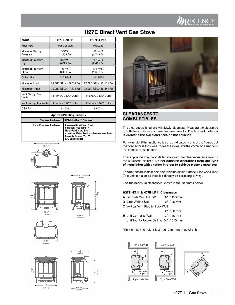
H27E Direct Vent Gas StoveModel H27E-NG11 H27E-LP11
FuelType NaturalGas Propane
MinimumSupplyPressure
5”W.C.(1.25kPa)
11”W.C.(2.74kPa)
ManifoldPressure-High
3.5”W.C.(0.87kPa)
10”W.C.(2.49kPa)
ManifoldPressure-Low
1.6”W.C.(0.40kPa)
6.4”W.C.(1.59kPa)
OrificeSize #42DMS #54DMS
MinimumInput 18,000BTU/h(5.28kW) 17,500BTU/h(5.13kW)
MaximumInput 25,000BTU/h(7.32kW) 22,000BTU/h(6.45kW)
VentSizing(RearVent)
4”Inner/6-5/8”Outer 4”Inner/6-5/8”Outer
VentSizing(TopVent) 4”Inner/6-5/8”Outer 4”Inner/6-5/8”Outer
CSAP.4.1 61.22% 63.07%
Approved Venting Systems
Flex Vent Systems: FPI AstroCap™ Flex Vent
Rigid Pipe Vent Systems: Simpson Direct Vent Pro®Selkirk Direct-Temp™Metal-Fab® Sure SealAmerican Metal Products® Amerivent DirectSecurity Secure-Vent™ICC Excel Direct
17 13/16”(452 mm)
17 13/16”(452 mm)
CLEARANCES TO COMBUSTIBLES
TheclearanceslistedareMINIMUMdistances.Measuretheclearancetoboththeapplianceandthechimneyconnector.The farthest distance is correct if the two clearances do not coincide.
Forexample,iftheapplianceissetasindicatedinoneofthefiguresbuttheconnectoristooclose,movethestoveuntilthecorrectclearancetotheconnectorisobtained.
Thisappliancemaybeinstalledonlywiththeclearancesasshowninthesituationspictured.Do not combine clearances from one type of installation with another in order to achieve closer clearances.
Thisunitcanbeinstalledonasolidcombustiblesurfacelikeawoodfloor.Thisunitcanalsobeinstalleddirectlyoncarpetingorvinyl.
Usetheminimumclearancesshowninthediagramsbelow:
H27E-NG11 & H27E-LP11 Clearances
A LeftSideWalltoUnit* 6"/150mm
B BackWalltoUnit 3"/75mm
CVerticalVentPipetoBackWall
2"/50mm
E UnitCornertoWall 2" /50mm
UnitToptoAlcoveCeiling 24" /610mm
Minimumceilingheightis24"/610mmfromtopofunit.
2| H27E-11GasStove
H27E-11 Gas Stove
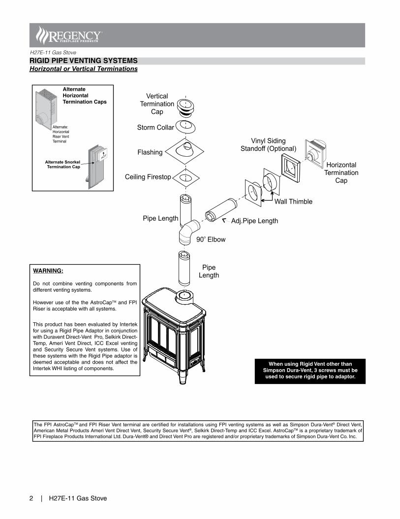
Pipe Length
VerticalTermination
Cap
Storm Collar
Flashing
Ceiling Firestop
PipeLength
Adj.Pipe Length
90 Elbowo
HorizontalTermination
Cap
Wall Thimble
Vinyl SidingStandoff (Optional)
RIGID PIPE VENTING SYSTEMSHorizontal or Vertical Terminations
Alternate HorizontalTermination Caps
When using Rigid Vent other thanSimpson Dura-Vent, 3 screws must be used to secure rigid pipe to adaptor.
TheFPIAstroCapTMandFPIRiserVentterminalarecertifiedfor installationsusingFPIventingsystemsaswellasSimpsonDura-Vent®DirectVent,AmericanMetalProductsAmeriVentDirectVent,SecuritySecureVent®,SelkirkDirect-TempandICCExcel.AstroCapTMisaproprietarytrademarkofFPIFireplaceProductsInternationalLtd.Dura-Vent®andDirectVentProareregisteredand/orproprietarytrademarksofSimpsonDura-VentCo.Inc.
ThisproducthasbeenevaluatedbyIntertekforusingaRigidPipeAdaptorinconjunctionwithDuraventDirect-VentPro,SelkirkDirect-Temp,AmeriVentDirect, ICCExcel ventingand Security Secure Vent systems. Use ofthesesystemswiththeRigidPipeadaptorisdeemedacceptableanddoesnot affect theIntertekWHIlistingofcomponents.
WARNING:
Do not combine venting components fromdifferentventingsystems.
Howeveruseof thetheAstroCapTMandFPIRiserisacceptablewithallsystems.
H27E-11GasStove |3
H27E-11 Gas Stove
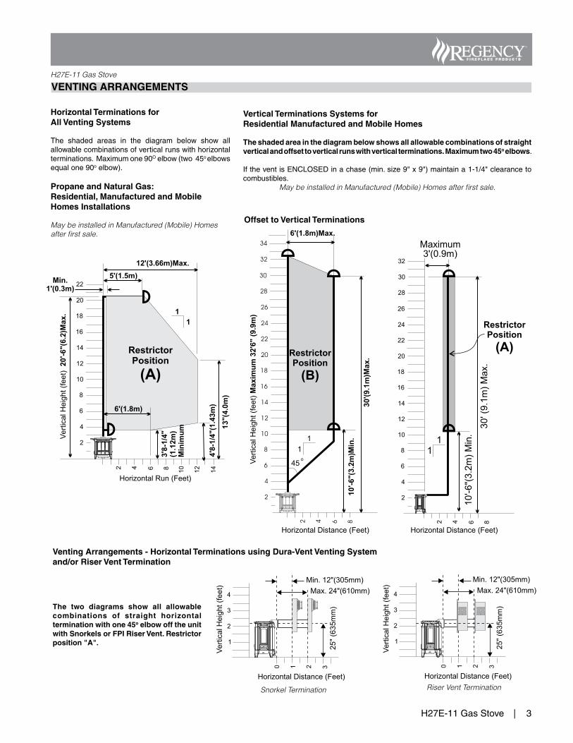
Offset to Vertical Terminations
Venting Arrangements - Horizontal Terminations using Dura-Vent Venting Systemand/or Riser Vent Termination
Snorkel Termination Riser Vent Termination
VENTING ARRANGEMENTS
Vertical Terminations Systems for Residential Manufactured and Mobile Homes
The shaded area in the diagram below shows all allowable combinations of straight vertical and offset to vertical runs with vertical terminations.Maximum two 45o elbows.
IftheventisENCLOSEDinachase(min.size9"x9")maintaina1-1/4"clearancetocombustibles.
May be installed in Manufactured (Mobile) Homes after first sale.
Horizontal Terminations for All Venting Systems
The shaded areas in the diagram below show allallowablecombinationsofverticalrunswithhorizontalterminations.Maximumone90Oelbow(two45oelbowsequalone90oelbow).
Propane and Natural Gas: Residential, Manufactured and Mobile Homes Installations
May be installed in Manufactured (Mobile) Homes after first sale.
The two diagrams show all allowable combinations of straight horizontal termination with one 45o elbow off the unit with Snorkels or FPI Riser Vent. Restrictor position "A".
4| H27E-11GasStove
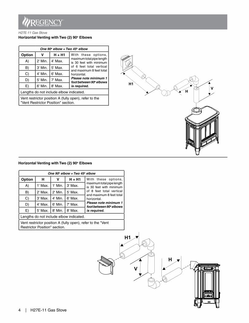
H27E-11 Gas StoveHorizontal Venting with Two (2) 90o Elbows
Horizontal Venting with Two (2) 90o Elbows
H
H1
V
One 90o elbow = Two 45o elbow
Option V H + H1 With these opt ions,maximumtotalpipelengthis 30 feet with minimumof 6 feet total verticalandmaximum8feettotalhorizontal.Please note minimum 1 foot between 90o elbows is required.
A) 2'Min. 4'Max.
B) 3'Min. 5'Max.
C) 4'Min. 6'Max.
D) 5'Min. 7'Max.
E) 6'Min. 8'Max.
Lengthsdonotincludeelbowindicated.
VentrestrictorpositionA(fullyopen),refertothe"VentRestrictorPosition"section.
One 90o elbow = Two 45o elbow
Option H V H + H1 With these opt ions,maximumtotalpipelengthis 30 feet with minimumof 8 feet total verticalandmaximum8feettotalhorizontal.Please note minimum 1 foot between 90o elbows is required.
A) 1'Max. 1'Min. 3'Max.
B) 2'Max. 2'Min. 5'Max.
C) 3'Max. 4'Min. 6'Max.
D) 4'Max. 6'Min. 7'Max.
E) 5'Max. 8'Min. 8'Max.
Lengthsdonotincludeelbowindicated.
VentrestrictorpositionA(fullyopen),refertothe"VentRestrictorPosition"section.
H27E-11GasStove |5
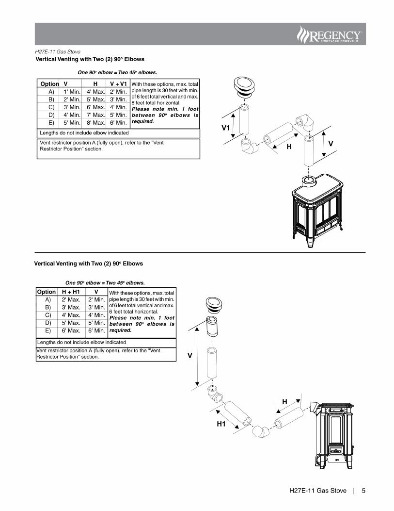
H27E-11 Gas StoveVertical Venting with Two (2) 90o Elbows
Vertical Venting with Two (2) 90o Elbows
One 90o elbow = Two 45o elbows.
V1
VH
Option V H V + V1 A) 1'Min. 4'Max. 2'Min. B) 2'Min. 5'Max. 3'Min. C) 3'Min. 6'Max. 4'Min. D) 4'Min. 7'Max. 5'Min. E) 5'Min. 8'Max. 6'Min.
Withtheseoptions,max.totalpipelengthis30feetwithmin.of6feettotalverticalandmax.8feettotalhorizontal.Please note min. 1 foot between 90o elbows is required.
Vent restrictor position A (fully open), refer to the "Vent Restrictor Position" section.
Lengthsdonotincludeelbowindicated
Option H + H1 V A) 2'Max. 2'Min. B) 3'Max. 3'Min. C) 4'Max. 4'Min. D) 5'Max. 5'Min. E) 6'Max. 6'Min.
Withtheseoptions,max.totalpipelengthis30feetwithmin.of6feettotalverticalandmax.6feettotalhorizontal.Please note min. 1 foot between 90o elbows is required.
One 90o elbow = Two 45o elbows.
VentrestrictorpositionA(fullyopen),refertothe"VentRestrictorPosition"section.
Lengthsdonotincludeelbowindicated
6| H27E-11GasStove
H27E-11 Gas Stove
Flex Liner
ExhaustFlue
A maximumof two certified
joiner kitsmay be used
per length.#948-305 (35 ft)
Air Intake
Co-linear DVVertical Termination
Cap # 946-529
Co-LinearFlex
Adapterwith Kit#946-563
OuterPipe
with Kit#946-563
Inner PipeAdapterwith Kit#946-563
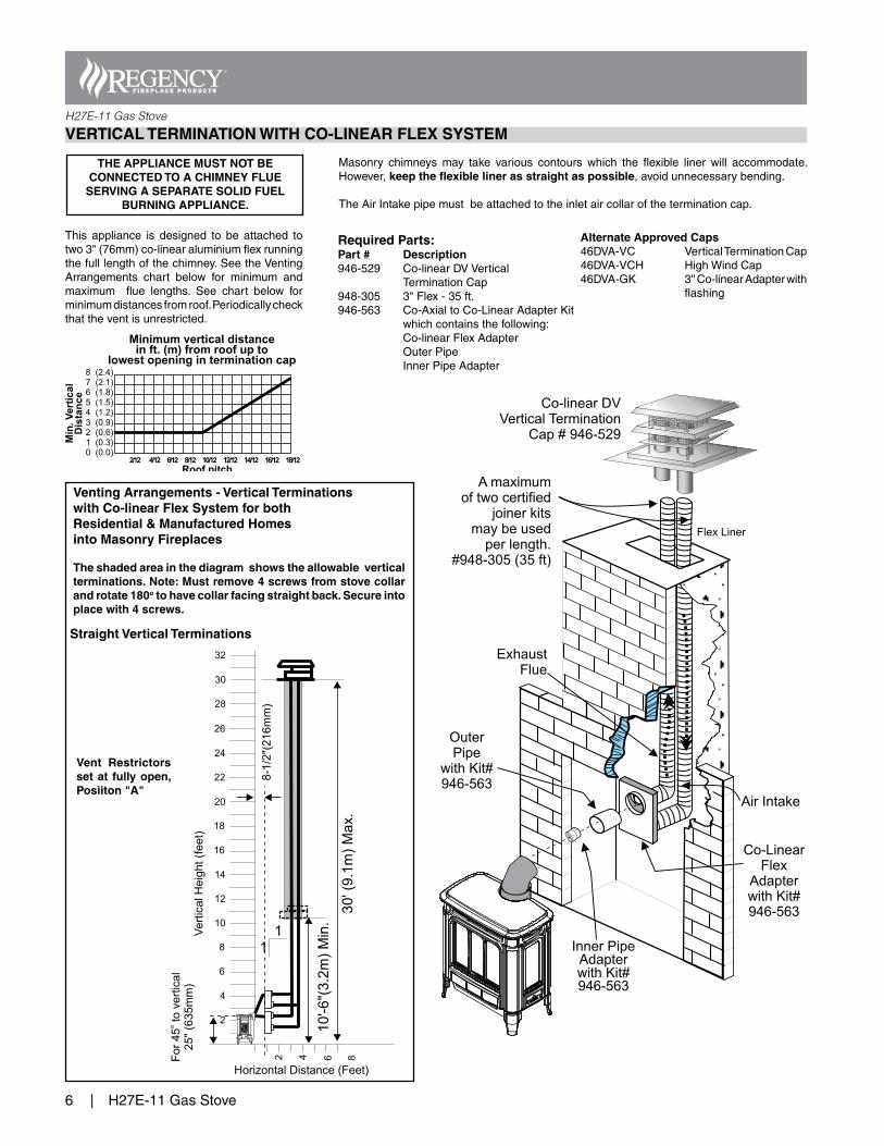
Venting Arrangements - Vertical Terminations with Co-linear Flex System for bothResidential & Manufactured Homes into Masonry Fireplaces
The shaded area in the diagram shows the allowable vertical terminations. Note: Must remove 4 screws from stove collar and rotate 180o to have collar facing straight back. Secure into place with 4 screws.
VERTICAL TERMINATION WITH CO-LINEAR FLEX SYSTEM
This appliance is designed to be attached totwo3"(76mm)co-linearaluminiumflexrunningthefulllengthofthechimney.SeetheVentingArrangements chart below for minimum andmaximum flue lengths. See chart below forminimumdistancesfromroof.Periodicallycheckthattheventisunrestricted.
Masonry chimneys may take various contours which the flexible liner will accommodate.However,keep the flexible liner as straight as possible,avoidunnecessarybending.
TheAirIntakepipemustbeattachedtotheinletaircollaroftheterminationcap.
Straight Vertical Terminations
Required Parts:Part # Description946-529 Co-linearDVVertical TerminationCap948-305 3"Flex-35ft.946-563 Co-AxialtoCo-LinearAdapterKit whichcontainsthefollowing: Co-linearFlexAdapter OuterPipe InnerPipeAdapter
Vent Restrictors set at fully open, Posiiton "A"
THE APPLIANCE MUST NOT BE CONNECTED TO A CHIMNEY FLUE
SERVING A SEPARATE SOLID FUELBURNING APPLIANCE.
Alternate Approved Caps46DVA-VC VerticalTerminationCap46DVA-VCH HighWindCap46DVA-GK 3''Co-linearAdapterwith flashing
H27E-11GasStove |7
H27E-11 Gas Stove
AdapterTrim Collar
4" ID Liner
SpacerSpring
ThimbleCover Termination Cap
(Part# 946-523/P)
AstroCap
Wall Thimble(required for
combustible walls)
Adjustable PipeLength 13-1/2" - 24",
2 pieces
4 ft. Pipe Lengthwith Kit # 946-216or 2 ft. Pipe Length withKit # 946-116
TrimCollar
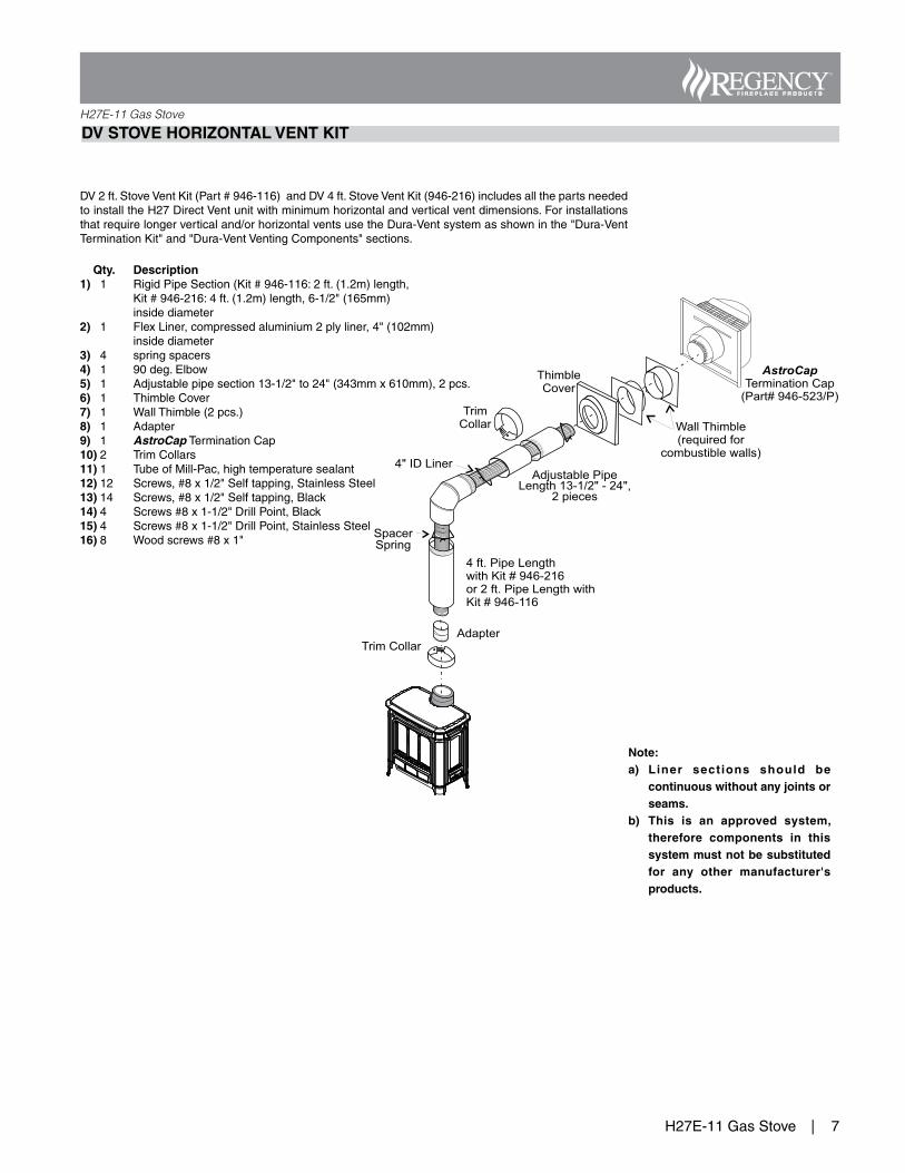
DV STOVE HORIZONTAL VENT KIT
DV2ft.StoveVentKit(Part#946-116)andDV4ft.StoveVentKit(946-216)includesallthepartsneededtoinstalltheH27DirectVentunitwithminimumhorizontalandverticalventdimensions.Forinstallationsthatrequirelongerverticaland/orhorizontalventsusetheDura-Ventsystemasshowninthe"Dura-VentTerminationKit"and"Dura-VentVentingComponents"sections.
Qty. Description1) 1 RigidPipeSection(Kit#946-116:2ft.(1.2m)length, Kit#946-216:4ft.(1.2m)length,6-1/2"(165mm) insidediameter2) 1 FlexLiner,compressedaluminium2plyliner,4"(102mm) insidediameter3) 4 springspacers4) 1 90deg.Elbow5) 1 Adjustablepipesection13-1/2"to24"(343mmx610mm),2pcs.6) 1 ThimbleCover7) 1 WallThimble(2pcs.)8) 1 Adapter9) 1 AstroCapTerminationCap10)2 TrimCollars11)1 TubeofMill-Pac,hightemperaturesealant12)12 Screws,#8x1/2"Selftapping,StainlessSteel13)14 Screws,#8x1/2"Selftapping,Black14)4 Screws#8x1-1/2"DrillPoint,Black15)4 Screws#8x1-1/2"DrillPoint,StainlessSteel16)8 Woodscrews#8x1"
Note: a) Liner sections should be
continuous without any joints or seams.
b) This is an approved system, therefore components in this system must not be substituted for any other manufacturer's products.
8| H27E-11GasStove
H27E-11 Gas Stove
Pipe Length (max. 18")Part (6-5/8" Dia)
(4" Dia.)
DecorativeWall Trim
HorizontalTerminalPart# 640-530/P
Wall Thimble(required for
combustible walls)
Vinyl SidingStandoff (Optional)Part #946-205
Adapter(required)
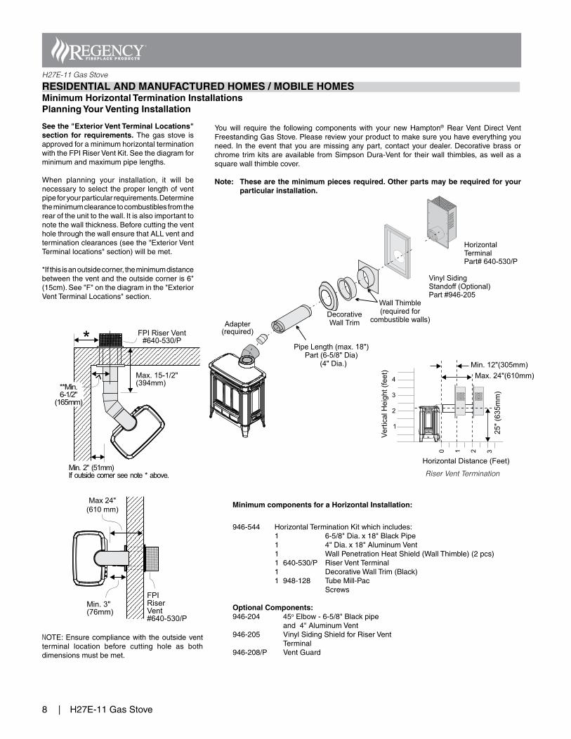
RESIDENTIAL AND MANUFACTURED HOMES / MOBILE HOMES Minimum Horizontal Termination InstallationsPlanning Your Venting Installation
You will require the following components with your new Hampton® RearVent DirectVentFreestandingGasStove.Pleasereviewyourproducttomakesureyouhaveeverythingyouneed. In theevent that youaremissinganypart, contact yourdealer.Decorativebrassorchrometrimkitsareavailable fromSimpsonDura-Vent for theirwall thimbles,aswellasasquarewallthimblecover.
Note: These are the minimum pieces required. Other parts may be required for your particular installation.
See the "Exterior Vent Terminal Locations" section for requirements. Thegasstove isapprovedforaminimumhorizontalterminationwiththeFPIRiserVentKit.Seethediagramforminimumandmaximumpipelengths.
When planning your installation, it will benecessarytoselecttheproper lengthofventpipeforyourparticularrequirements.Determinetheminimumclearancetocombustiblesfromtherearoftheunittothewall.Itisalsoimportanttonotethewallthickness.BeforecuttingtheventholethroughthewallensurethatALLventandterminationclearances(seethe"ExteriorVentTerminallocations"section)willbemet.
*Ifthisisanoutsidecorner,theminimumdistancebetweentheventandtheoutsidecorneris6"(15cm).See"F"onthediagraminthe"ExteriorVentTerminalLocations"section.
NOTE:Ensurecompliancewith theoutsideventterminal location before cutting hole as bothdimensionsmustbemet.
Minimum components for a Horizontal Installation:
946-544 HorizontalTerminationKitwhichincludes: 1 6-5/8"Dia.x18"BlackPipe 1 4"Dia.x18"AluminumVent 1 WallPenetrationHeatShield(WallThimble)(2pcs) 1 640-530/P RiserVentTerminal 1 DecorativeWallTrim(Black) 1 948-128 TubeMill-Pac Screws
Optional Components:946-204 45oElbow-6-5/8"Blackpipe and4"AluminumVent946-205 VinylSidingShieldforRiserVent Terminal946-208/P VentGuard
FPI Riser Vent#640-530/P
Max. 15-1/2"(394mm)
Min. 2" (51mm)If outside corner see note * above.
*
**Min.6-1/2"
(165mm)
Max. 23-1/2"(597mm)
Min. 3"(76mm)
FPIRiserVent#640-530/P
Riser Vent Termination
Max 24" (610 mm)
H27E-11GasStove |9
H27E-11 Gas Stove
Pipe Length
Round SupportBox/Wall Thimble
VerticalTerminal
Storm Collar
Flashing(0-12/6-12)
CeilingFirestop
Pipe Length(included in 46DVA-KHA)
Dura-Vent Horizontal
Termination Installation
Dura-Vent Vertical
Termination Installation
*Adj.Pipe Length(included in #46DVA-KHA)
*90 Elbow(included in 46DVA-KHA)
o
*Round SupportBox/Wall Thimble(included in 46DVA-KHA)
*HorizontalTermination Cap(included in 46DVA-KHA)
Wall Thimble(B) Part # 46DVA-WT
Vinyl SidingStandoff (Optional)
Part #46DVA-VSS
CathedralCeiling
Support Box
(D)
Vertical Termination Kit
Part # 46DVA-KVA (A)
*Horizontal Termination Kit
Part # 46DVA-KHA
Basic Horizontal Kit
1 90oElbow1 WallThimbleCover1 Horiz.Sq.Term.Cap
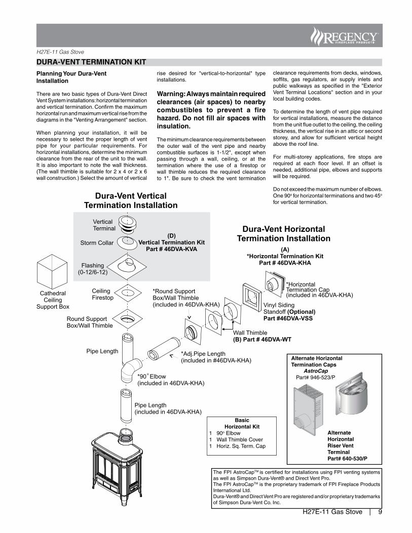
DURA-VENT TERMINATION KIT
Planning Your Dura-Vent Installation
TherearetwobasictypesofDura-VentDirectVentSysteminstallations:horizontalterminationandverticaltermination.Confirmthemaximumhorizontalrunandmaximumverticalrisefromthediagramsinthe"VentingArrangement"section.
When planning your installation, it will benecessary toselect theproper lengthofventpipe for your particular requirements. Forhorizontalinstallations,determinetheminimumclearancefromtherearoftheunittothewall.It isalso important tonotethewall thickness.(Thewallthimbleissuitablefor2x4or2x6wallconstruction.)Selecttheamountofvertical
rise desired for "vertical-to-horizontal" typeinstallations.
Warning: Always maintain required clearances (air spaces) to nearby combustibles to prevent a fire hazard. Do not fill air spaces with insulation.
Theminimumclearancerequirementsbetweenthe outer wall of the vent pipe and nearbycombustible surfaces is 1-1/2", except whenpassing through a wall, ceiling, or at thetermination where the use of a firestop orwall thimble reduces the required clearanceto 1". Be sure to check the vent termination
clearancerequirementsfromdecks,windows,soffits, gas regulators, air supply inlets andpublicwalkwaysasspecified in the "ExteriorVentTerminalLocations"sectionand inyourlocalbuildingcodes.
Todeterminethelengthofventpiperequiredforverticalinstallations,measurethedistancefromtheunitflueoutlettotheceiling,theceilingthickness,theverticalriseinanatticorsecondstorey,andallow for sufficient verticalheightabovetheroofline.
For multi-storey applications, fire stops arerequired at each floor level. If an offset isneeded,additionalpipe,elbowsandsupportswillberequired.
Donotexceedthemaximumnumberofelbows.One90oforhorizontalterminationsandtwo45oforverticaltermination.
AstroCapPart#946-523/P
Alternate Horizontal Termination Caps
Alternate Horizontal Riser Vent Terminal Part# 640-530/P
TheFPIAstroCapTMiscertifiedforinstallationsusingFPIventingsystemsaswellasSimpsonDura-Vent®andDirectVentPro.TheFPIAstroCapTMistheproprietarytrademarkofFPIFireplaceProductsInternationalLtd.Dura-Vent®andDirectVentProareregisteredand/orproprietarytrademarksofSimpsonDura-VentCo.Inc.