h.4 seismic slope stability analyses - lake … calculation package was prepared as part of the...
TRANSCRIPT
DRAFT ONONDAGA LAKECAPPING AND DREDGE AREA AND DEPTH
INITIAL DESIGN SUBMITTAL
Parsons P:\Honeywell -SYR\444576 2008 Capping\09 Reports\9.3 December 2009_Capping and Dredge Area & Depth IDS\Capping IDS.doc 12/10/2009
H.4
SEISMIC SLOPE STABILITY ANALYSES
Page 1 of 27
Written by: Fan Zhu Date: 11/18/2009 Reviewed by: Ming Zhu/R. Kulasingam/Jay Beech Date: 11/19/2009
Client: Honeywell Project: Onondaga Lake ILWD Stability Project/ Proposal No.: GJ4204 Task No.: 14-05
GA090668/ILWD_Seismic Package _v4.doc
SEISMIC SLOPE STABILITY ANALYSES
INTRODUCTION
This calculation package was prepared as part of the Remediation Area D geotechnical stability analysis for the Onondaga Lake Bottom Site. Specifically, the purpose of this package is to present seismic slope stability analyses for Remediation Area D after capping. Remediation Area D, which is also referred to as the In-Lake Waste Deposit (ILWD), is shown in Figure 1. Remediation Area D consists predominantly of Sediment Management Unit (SMU) 1 with limited portions of SMUs 2 and 7. The seismic slope stability of both (i) overall general cross sections along the ILWD slope and (ii) localized areas that have relatively steep slopes was evaluated for the condition after capping.
It should be noted that:
(1) Information regarding hot spot dredging (i.e., localized deeper dredging areas) in Remediation Area D was not available when the analyses presented in this package were performed, and therefore, was not included in the analyses; and
(2) The cap configurations used in the analyses presented herein were based on the preliminary cap design provided to Geosyntec by Parsons. For the purpose of the analyses presented herein, the expected potentially critical condition with the maximum potential difference in cap thickness was assumed, as described later in this package. The cap was assumed to be constructed to not liquefy when subjected to the contingency earthquake event. If necessary, additional evaluations will be performed, when more cap construction details are available.
METHODOLOGY
Seismic Slope Stability
Seismic slope stability analyses were performed using Spencer’s method [Spencer, 1973], as implemented in the computer program SLIDE, version 5.0 [Rocscience, 2006]. Rotational type failure mode, i.e. circular slip surface, was considered to assess the pseudostatic slope stability factor of safety (FS) of the selected cross sections. Wedge type slip surfaces were not considered applicable for Remediation Area D because they
Page 2 of 27
Written by: Fan Zhu Date: 11/18/2009 Reviewed by: Ming Zhu/R. Kulasingam/Jay Beech Date: 11/19/2009
Client: Honeywell Project: Onondaga Lake ILWD Stability Project/ Proposal No.: GJ4204 Task No.: 14-05
GA090668/ILWD_Seismic Package _v4.doc
generally only apply when known weak layers or interfaces are present. Regardless, an independent analysis was performed assuming wedge type slip surfaces. The results indicated that the FSs calculated using the wedge type slip surfaces were greater than those calculated using the circular slip surfaces. Therefore, only circular slip surfaces were evaluated. Detailed discussion regarding Spencer’s method and the SLIDE program is presented in Appendix H.3 of the Draft Onondaga Lake Capping and Dredge Area & Depth Initial Design Submittal in a calculation package titled “Static Slope Stability Analyses” (referred to as the Static Stability Package). The procedure for the seismic slope stability analysis presented herein is summarized as follows:
• Select a pseudostatic coefficient to reduce the maximum horizontal acceleration for use in slope stability analyses. This is done in recognition that maximum acceleration exists only for a very short time [Kramer, 1996]. Based on the discussions presented in the Federal Highway Administration’s seismic design guidance document [Kavazanjian et al., 1997], a pseudostatic coefficient of 0.5 was conservatively selected for this seismic slope stability evaluation.
• Calculate the horizontal seismic coefficient (k) by multiplying the maximum horizontal acceleration by the pseudostatic coefficient. A maximum horizontal acceleration of 0.09g was selected for a contingency level event (i.e., a seismic event with a 10 percent chance of exceedance in 50 years) at the site, as required in the Statement of Work of the Consent Decree for the Onondaga Lake Bottom Subsite (United States District Court, 2007) and as presented in Appendix H.2 of the Draft Onondaga Lake Capping and Dredge Area & Depth Initial Design Submittal in a calculation package titled “Liquefaction Potential Analysis” (referred to as the Liquefaction Package). Using this maximum horizontal acceleration of 0.09g and a pseudostatic coefficient of 0.5, a horizontal seismic coefficient (k) of 0.045g was calculated for the seismic analysis.
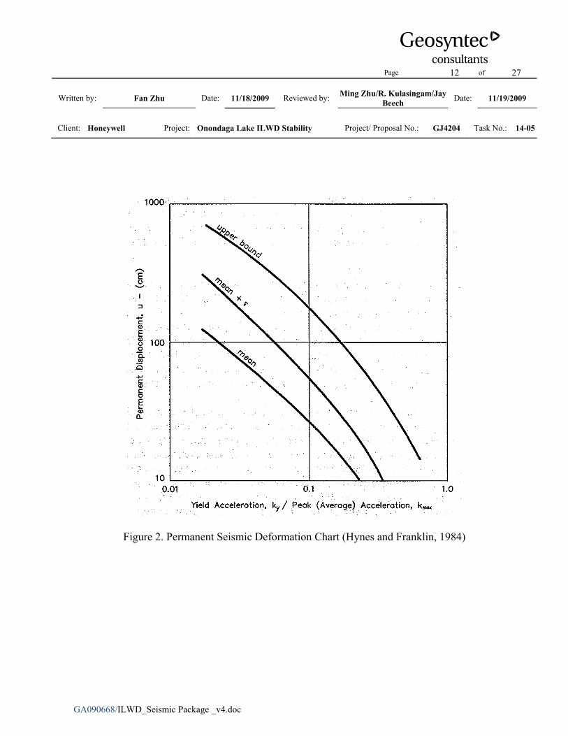
• Perform pseudostatic slope stability analyses by applying a horizontal seismic coefficient to the same procedures used for static slope stability analyses. If the calculated pseudostatic FS is greater than 1.1, the slope is considered to have an acceptable FS under the contingency level seismic event (i.e., a seismic event of 10 percent chance of exceedance in 50 years). If the calculated pseudostatic FS is less than 1.1, calculate permanent seismic displacements by performing deformation analysis and compare the calculated displacement to allowable displacements. Calculate the yield acceleration (i.e., the horizontal seismic coefficient that results in a
Page 3 of 27
Written by: Fan Zhu Date: 11/18/2009 Reviewed by: Ming Zhu/R. Kulasingam/Jay Beech Date: 11/19/2009
Client: Honeywell Project: Onondaga Lake ILWD Stability Project/ Proposal No.: GJ4204 Task No.: 14-05
GA090668/ILWD_Seismic Package _v4.doc
calculated FS of 1.0) and estimate permanent displacements using the Hynes and Franklin [1984] chart (Figure 2).
SUBSURFACE STRATIGRAPHY
Detailed information regarding the subsurface stratigraphy is presented in Appendix H.1 of the Draft Onondaga Lake Capping and Dredge Area & Depth Initial Design Submittal in a calculation package titled “Summary of Subsurface Stratigraphy and Material Properties” (referred to as the Data Package). In summary, the subsurface stratigraphy primarily consists of the following materials: Solvay Waste (SOLW), Marl, Silt and Clay, Silt and Sand, Sand and Gravel, Till, and Shale. In isolated areas of the ILWD, thin silt layers are present over the SOLW. The elevation of the lake water surface in the ILWD was assumed to be El. 363 feet above mean sea level (NAVD88), as presented in the Data Package.
The subsurface profile of the ILWD was developed based on the elevation of each layer from the boring logs provided by Parsons. As explained in the Data Package, the deeper surfaces (e.g., bottom of Silt and Clay, bottom of Silt and Sand) that were below the depth of shallow borings were developed based on a limited number of deeper borings in the ILWD. Since critical slip surfaces identified in the analyses are generally located within depths that were covered by the shallower borings (i.e., borings that terminated in or above the Silt and Clay layer), this is not expected to affect the seismic slope stability evaluation.
ANALYZED CROSS SECTIONS
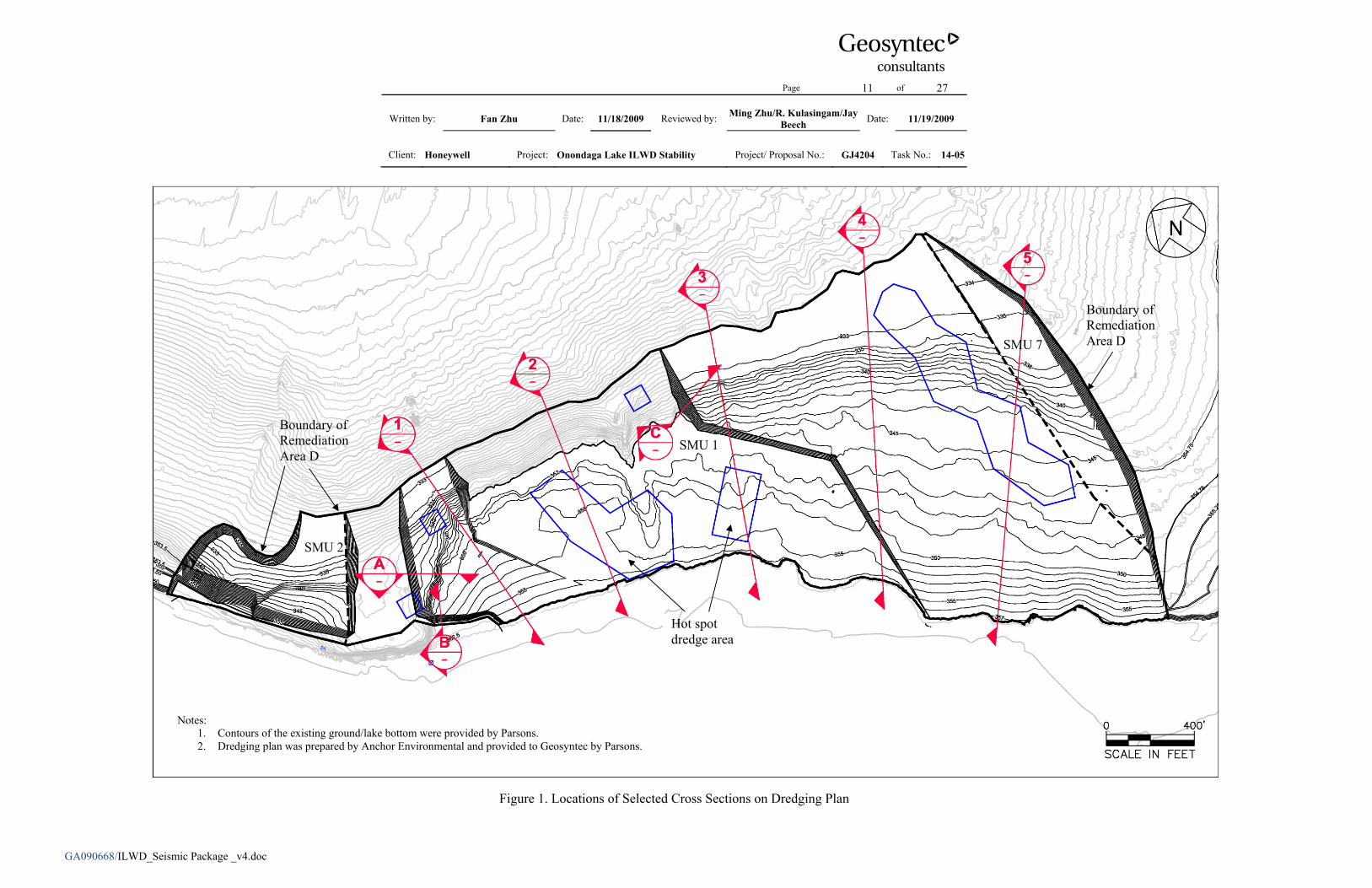
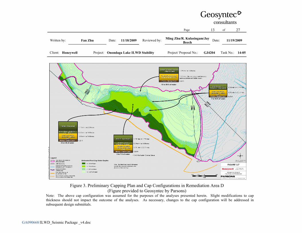
As shown on the proposed dredging plan in Figure 1, eight cross sections were selected for the stability analyses. The dredging plan was developed by Anchor Environmental and provided to Geosyntec by Parsons. Cross Sections 1 through 5 were selected to represent the overall general slope of the ILWD. Cross Sections A to C were selected to represent potentially critical localized steep slopes. The preliminary capping plan and cap configurations in the Remediation Area D are shown in Figure 3. As indicated in the figure, the proposed cap consists of layers of sand and/or gravel and the total cap thickness varies with the water depth. The minimum and maximum thicknesses of each cap component corresponding to four ranges of water depths were provided in the figure. It should be noted that the most recent version of the cap configuration was not
Page 4 of 27
Written by: Fan Zhu Date: 11/18/2009 Reviewed by: Ming Zhu/R. Kulasingam/Jay Beech Date: 11/19/2009
Client: Honeywell Project: Onondaga Lake ILWD Stability Project/ Proposal No.: GJ4204 Task No.: 14-05
GA090668/ILWD_Seismic Package _v4.doc
available during preparation of the analyses presented herein; however, slight modifications to cap thickness should not affect the outcome of these analyses. As necessary, these modifications will be addressed in subsequent design submittals.
For the overall general slopes after the entire Remediation Area D is capped, the condition where the cap in 10 to 30 ft of water has the minimum total thickness, while the caps in other areas have the maximum total thicknesses was found to be the potentially critical condition based on a preliminary analysis. The same cap configuration for the overall general slopes was applied to the localized steep slopes. The analyzed geometries of Cross Sections 1 through 5 and Cross Sections A through C after capping are presented in Figures 4 to 11. As mentioned in the beginning of this package, dredging in hot spots was not included in these cross sections. It should be noted that these assumptions should be reviewed after the final cap design is developed to determine if additional analyses are needed.
MATERIAL PROPERTIES
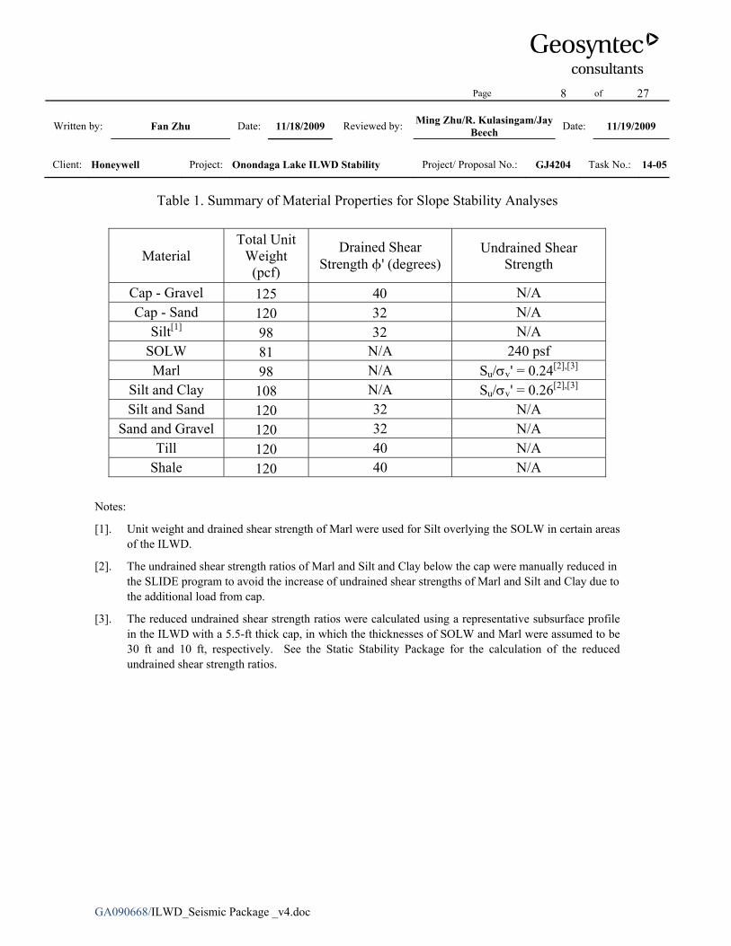
Detailed information related to the selection of subsurface material properties was presented in the Data Package. Table 1 summarizes the material properties (i.e., unit weights and shear strengths) of each subsurface material and the cap materials (i.e., the gravel and the sand) used in the slope stability analyses.
Based on the material type, the appropriate undrained and drained material properties were used in the analyses. Specifically, drained shear strength properties were used for Silt and Sand, Sand and Gravel, Till, and Shale. The drained properties of Marl were used for the silt in isolated areas of the ILWD. The sand and gravel material in the proposed cap were modeled with drained strength parameters by assuming that the cap will be constructed not to liquefy during the design earthquake as stated previously. Undrained shear strength properties were used for SOLW, Marl, and Silt and Clay, as they are fine grained materials and take a relatively long time to dissipate pore pressures generated under seismic loading conditions. As described for the after-capping condition in the Static Stability Package (see Material Properties section and Attachment 1 of that package), the undrained shear strength ratios of Marl and Silt and Clay were also manually reduced for the analyses presented herein.
Page 5 of 27
Written by: Fan Zhu Date: 11/18/2009 Reviewed by: Ming Zhu/R. Kulasingam/Jay Beech Date: 11/19/2009
Client: Honeywell Project: Onondaga Lake ILWD Stability Project/ Proposal No.: GJ4204 Task No.: 14-05
GA090668/ILWD_Seismic Package _v4.doc
RESULTS AND CONCLUSIONS
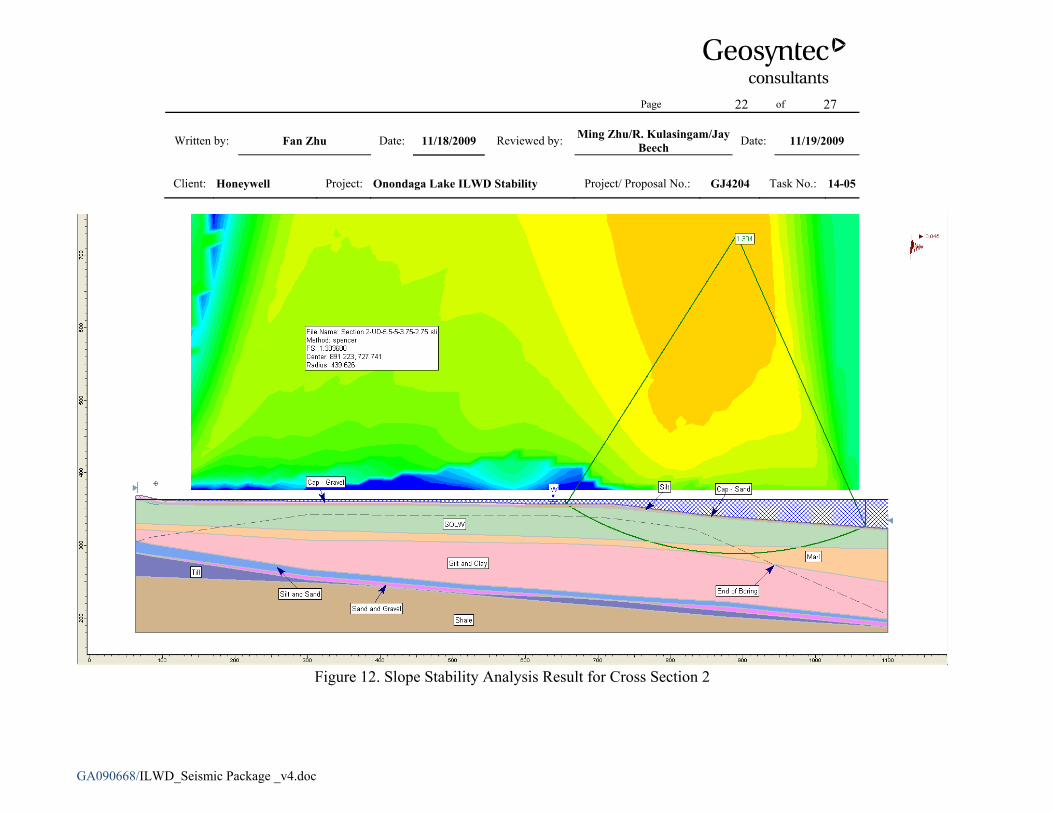
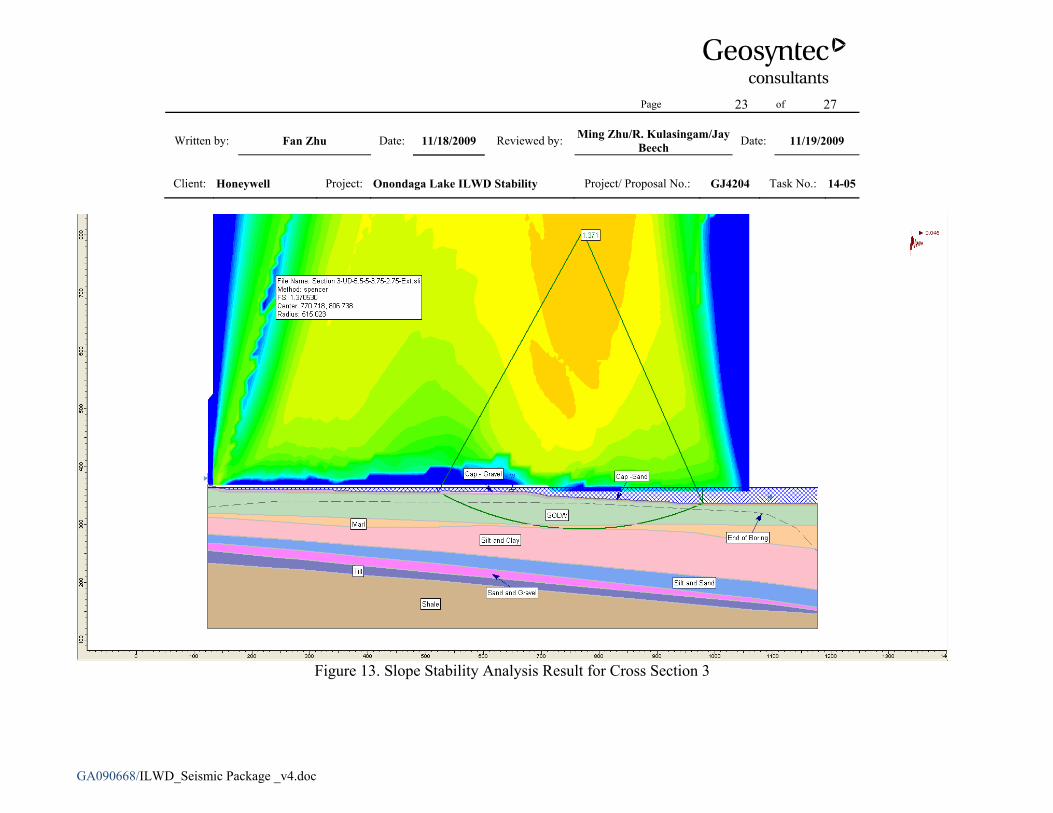
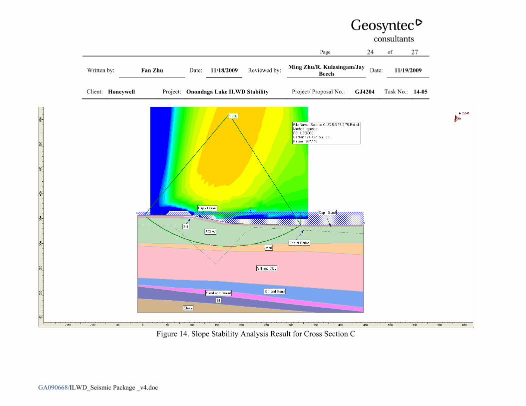
The seismic slope stability of Remediation Area D after capping was evaluated for five overall general slope cross sections (i.e., Cross Sections 1 through 5) and three localized steep slope cross sections (i.e., Cross Sections A through C). The results of seismic slope stability analyses are summarized in Table 2. As examples, the critical circular slip surfaces for Cross Sections 2, 3, and C are shown in Figures 12 through 14.
Under the after-capping condition, the calculated seismic slope stability FSs for the selected eight cross sections range from 1.3 to 2.0. The results indicate that the selected cross sections have acceptable calculated FSs after capping in case of a contingency level seismic event.
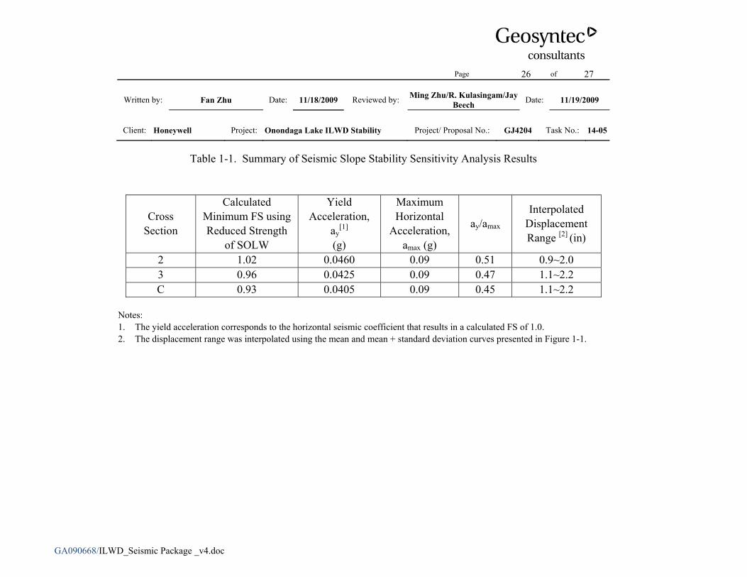
Additional analyses were performed to evaluate the sensitivity of the seismic slope stability to the undrained shear strength of SOLW. The three most critical cross sections, i.e., Cross Sections 2, 3, and C, were selected for the sensitivity analysis. In the sensitivity analysis, the SOLW shear strength value was reduced to represent the mean minus one standard deviation (i.e., 165 psf for the undrained shear strength), which was calculated based on the laboratory tests. The FSs for these three cross sections were calculated to be 1.02, 0.96, and 0.93, respectively, for the seismic condition after capping using the reduced undrained shear strength of SOLW. Because the calculated FS is less than the target FS of 1.1, a deformation analysis was performed for these cross sections. The seismic displacements were estimated to range from 0.9 to 2.0 inches for Cross Section 2 and 1.1 to 2.2 inches for Cross Sections 3 and C, which were considered to be acceptable. The analysis results are presented in Attachment 1.
Page 6 of 27
Written by: Fan Zhu Date: 11/18/2009 Reviewed by: Ming Zhu/R. Kulasingam/Jay Beech Date: 11/19/2009
Client: Honeywell Project: Onondaga Lake ILWD Stability Project/ Proposal No.: GJ4204 Task No.: 14-05
GA090668/ILWD_Seismic Package _v4.doc
REFERENCES
Hynes, M.E., and Franklin, A. G., “Rationalizing the Seismic Coefficient Method,” Miscellaneous Paper GL-84-13, U.S Army Engineer Waterways Experiment Station, Vicksburg, Mississippi, 1984.
Kavazanjian, E., Matasovic, N., Hadji-Hamou, T., and Sabatini, P. J., “Design Guidance: Geotechnical Earthquake Engineering for Highways – Design Priciples,” Volume I, Publication No. FHWA-SA-97-076, U.S. Department of Transportation, 1997.
Kramer, S., “Geotechnical Earthquake Engineering,” Prentice Hall, NY, 1996.
Rocscience, “SLIDE – 2-D Limit Equilibrium Slope Stability for Soil and Rock Slopes,” User's Guide, Rocscience Software, Inc., Toronto, Ontario, Canada, 2006.
Spencer, E., “The Thrust Line Criterion in Embankment Stability Analysis,” Géotechnique, Vol. 23, No. 1, pp. 85-100, March 1973.
United States District Court, Northern District of New York. State of New York and Denise M. Sheehan against Honeywell International, Inc. Consent Decree Between the State of New York and Honeywell International, Inc. Senior Judge Scullin, Dated October 11, 2006. Filed January 4, 2007.

Page 7 of 27
Written by: Fan Zhu Date: 11/18/2009 Reviewed by: Ming Zhu/R. Kulasingam/Jay Beech Date: 11/19/2009
Client: Honeywell Project: Onondaga Lake ILWD Stability Project/ Proposal No.: GJ4204 Task No.: 14-05
GA090668/ILWD_Seismic Package _v4.doc
Tables
Page 8 of 27
Written by: Fan Zhu Date: 11/18/2009 Reviewed by: Ming Zhu/R. Kulasingam/Jay Beech Date: 11/19/2009
Client: Honeywell Project: Onondaga Lake ILWD Stability Project/ Proposal No.: GJ4204 Task No.: 14-05
GA090668/ILWD_Seismic Package _v4.doc
Table 1. Summary of Material Properties for Slope Stability Analyses
Material Total Unit
Weight (pcf)
Drained Shear Strength φ' (degrees)
Undrained Shear Strength
Cap - Gravel 125 40 N/A Cap - Sand 120 32 N/A
Silt[1] 98 32 N/A SOLW 81 N/A 240 psf Marl 98 N/A Su/σv' = 0.24[2],[3]
Silt and Clay 108 N/A Su/σv' = 0.26[2],[3] Silt and Sand 120 32 N/A
Sand and Gravel 120 32 N/A Till 120 40 N/A
Shale 120 40 N/A
Notes:
[1]. Unit weight and drained shear strength of Marl were used for Silt overlying the SOLW in certain areas of the ILWD.
[2]. The undrained shear strength ratios of Marl and Silt and Clay below the cap were manually reduced in the SLIDE program to avoid the increase of undrained shear strengths of Marl and Silt and Clay due to the additional load from cap.
[3]. The reduced undrained shear strength ratios were calculated using a representative subsurface profile in the ILWD with a 5.5-ft thick cap, in which the thicknesses of SOLW and Marl were assumed to be 30 ft and 10 ft, respectively. See the Static Stability Package for the calculation of the reduced undrained shear strength ratios.
Page 9 of 27
Written by: Fan Zhu Date: 11/18/2009 Reviewed by: Ming Zhu/R. Kulasingam/Jay Beech Date: 11/19/2009
Client: Honeywell Project: Onondaga Lake ILWD Stability Project/ Proposal No.: GJ4204 Task No.: 14-05
GA090668/ILWD_Seismic Package _v4.doc
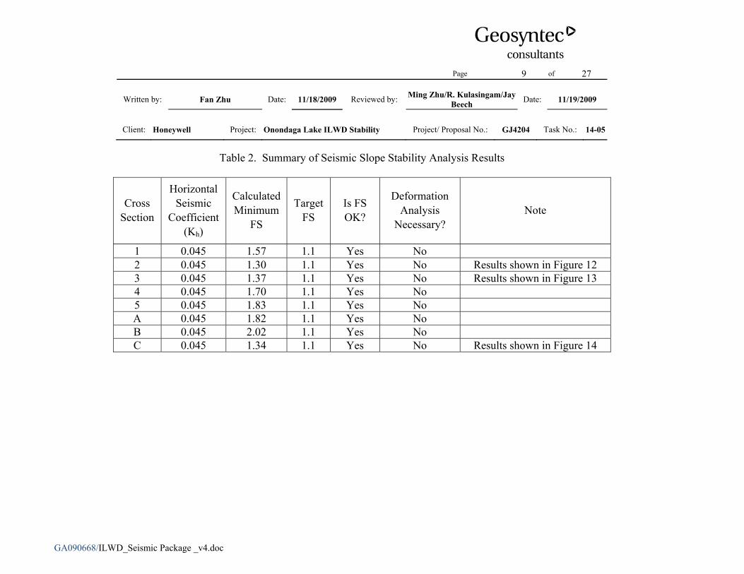
Table 2. Summary of Seismic Slope Stability Analysis Results
Cross Section
Horizontal Seismic
Coefficient (Kh)
Calculated Minimum
FS
Target FS
Is FS OK?
Deformation Analysis
Necessary? Note
1 0.045 1.57 1.1 Yes No 2 0.045 1.30 1.1 Yes No Results shown in Figure 12 3 0.045 1.37 1.1 Yes No Results shown in Figure 13 4 0.045 1.70 1.1 Yes No 5 0.045 1.83 1.1 Yes No A 0.045 1.82 1.1 Yes No B 0.045 2.02 1.1 Yes No C 0.045 1.34 1.1 Yes No Results shown in Figure 14
Page 10 of 27
Written by: Fan Zhu Date: 11/18/2009 Reviewed by: Ming Zhu/R. Kulasingam/Jay Beech Date: 11/19/2009
Client: Honeywell Project: Onondaga Lake ILWD Stability Project/ Proposal No.: GJ4204 Task No.: 14-05
GA090668/ILWD_Seismic Package _v4.doc
Figures
Page 11 of 27
Written by: Fan Zhu Date: 11/18/2009 Reviewed by: Ming Zhu/R. Kulasingam/Jay Beech Date: 11/19/2009
Client: Honeywell Project: Onondaga Lake ILWD Stability Project/ Proposal No.: GJ4204 Task No.: 14-05
GA090668/ILWD_Seismic Package _v4.doc
Figure 1. Locations of Selected Cross Sections on Dredging Plan
SMU 1
SMU 7
SMU 2
Boundary of Remediation Area D
Boundary of Remediation Area D
Hot spot dredge area
Notes: 1. Contours of the existing ground/lake bottom were provided by Parsons. 2. Dredging plan was prepared by Anchor Environmental and provided to Geosyntec by Parsons.
Page 12 of 27
Written by: Fan Zhu Date: 11/18/2009 Reviewed by: Ming Zhu/R. Kulasingam/Jay Beech Date: 11/19/2009
Client: Honeywell Project: Onondaga Lake ILWD Stability Project/ Proposal No.: GJ4204 Task No.: 14-05
GA090668/ILWD_Seismic Package _v4.doc
Figure 2. Permanent Seismic Deformation Chart (Hynes and Franklin, 1984)
Page 13 of 27
Written by: Fan Zhu Date: 11/18/2009 Reviewed by: Ming Zhu/R. Kulasingam/Jay Beech Date: 11/19/2009
Client: Honeywell Project: Onondaga Lake ILWD Stability Project/ Proposal No.: GJ4204 Task No.: 14-05
GA090668/ILWD_Seismic Package _v4.doc
Figure 3. Preliminary Capping Plan and Cap Configurations in Remediation Area D (Figure provided to Geosyntec by Parsons)
Note: The above cap configuration was assumed for the purposes of the analyses presented herein. Slight modifications to cap thickness should not impact the outcome of the analyses. As necessary, changes to the cap configuration will be addressed in subsequent design submittals.
Page 14 of 27
Written by: Fan Zhu Date: 11/18/2009 Reviewed by: Ming Zhu/R. Kulasingam/Jay Beech Date: 11/19/2009
Client: Honeywell Project: Onondaga Lake ILWD Stability Project/ Proposal No.: GJ4204 Task No.: 14-05
GA090668/ILWD_Seismic Package _v4.doc
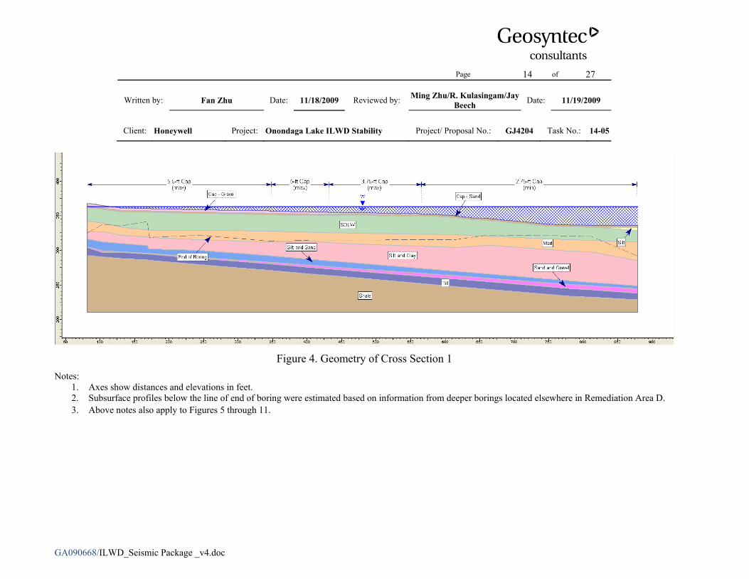
Figure 4. Geometry of Cross Section 1
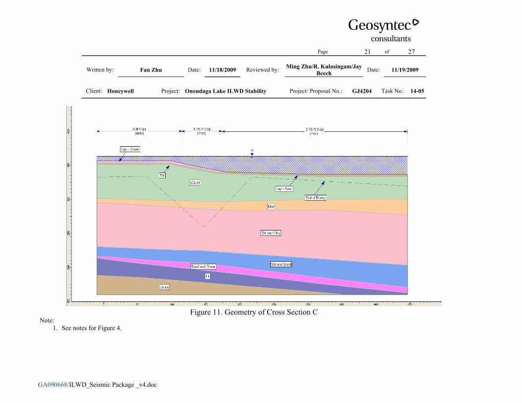
Notes: 1. Axes show distances and elevations in feet. 2. Subsurface profiles below the line of end of boring were estimated based on information from deeper borings located elsewhere in Remediation Area D. 3. Above notes also apply to Figures 5 through 11.
Page 15 of 27
Written by: Fan Zhu Date: 11/18/2009 Reviewed by: Ming Zhu/R. Kulasingam/Jay Beech Date: 11/19/2009
Client: Honeywell Project: Onondaga Lake ILWD Stability Project/ Proposal No.: GJ4204 Task No.: 14-05
GA090668/ILWD_Seismic Package _v4.doc
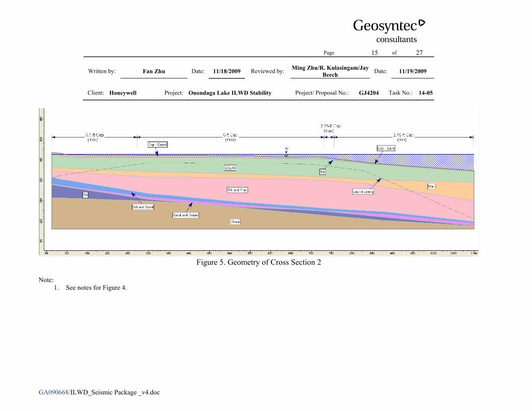
Figure 5. Geometry of Cross Section 2
Note:
1. See notes for Figure 4.
Page 16 of 27
Written by: Fan Zhu Date: 11/18/2009 Reviewed by: Ming Zhu/R. Kulasingam/Jay Beech Date: 11/19/2009
Client: Honeywell Project: Onondaga Lake ILWD Stability Project/ Proposal No.: GJ4204 Task No.: 14-05
GA090668/ILWD_Seismic Package _v4.doc
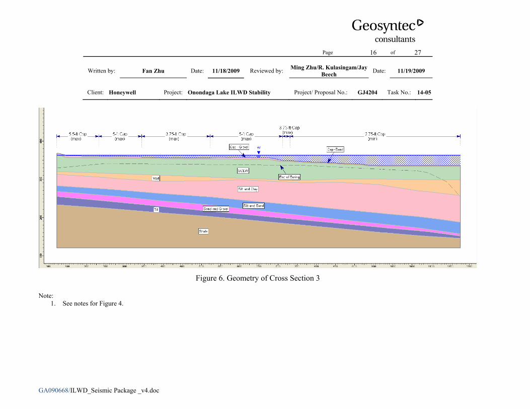
Figure 6. Geometry of Cross Section 3
Note:
1. See notes for Figure 4.
Page 17 of 27
Written by: Fan Zhu Date: 11/18/2009 Reviewed by: Ming Zhu/R. Kulasingam/Jay Beech Date: 11/19/2009
Client: Honeywell Project: Onondaga Lake ILWD Stability Project/ Proposal No.: GJ4204 Task No.: 14-05
GA090668/ILWD_Seismic Package _v4.doc
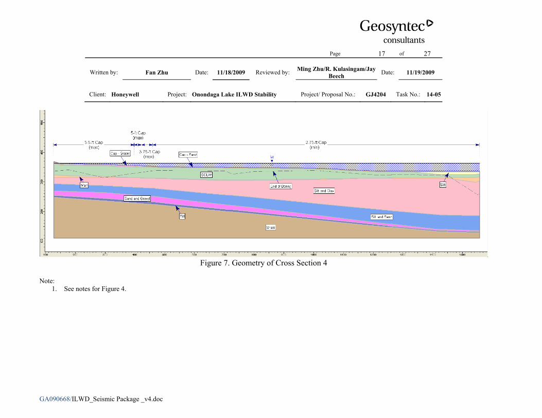
Figure 7. Geometry of Cross Section 4
Note:
1. See notes for Figure 4.
Page 18 of 27
Written by: Fan Zhu Date: 11/18/2009 Reviewed by: Ming Zhu/R. Kulasingam/Jay Beech Date: 11/19/2009
Client: Honeywell Project: Onondaga Lake ILWD Stability Project/ Proposal No.: GJ4204 Task No.: 14-05
GA090668/ILWD_Seismic Package _v4.doc
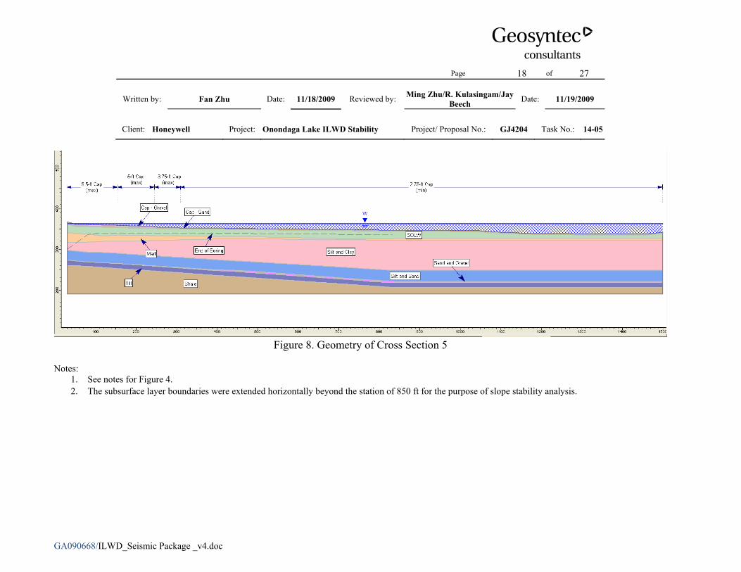
Figure 8. Geometry of Cross Section 5
Notes:
1. See notes for Figure 4. 2. The subsurface layer boundaries were extended horizontally beyond the station of 850 ft for the purpose of slope stability analysis.
Page 19 of 27
Written by: Fan Zhu Date: 11/18/2009 Reviewed by: Ming Zhu/R. Kulasingam/Jay Beech Date: 11/19/2009
Client: Honeywell Project: Onondaga Lake ILWD Stability Project/ Proposal No.: GJ4204 Task No.: 14-05
GA090668/ILWD_Seismic Package _v4.doc
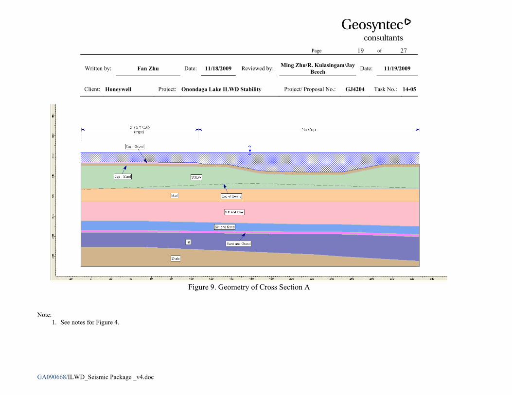
Figure 9. Geometry of Cross Section A
Note: 1. See notes for Figure 4.
Page 20 of 27
Written by: Fan Zhu Date: 11/18/2009 Reviewed by: Ming Zhu/R. Kulasingam/Jay Beech Date: 11/19/2009
Client: Honeywell Project: Onondaga Lake ILWD Stability Project/ Proposal No.: GJ4204 Task No.: 14-05
GA090668/ILWD_Seismic Package _v4.doc
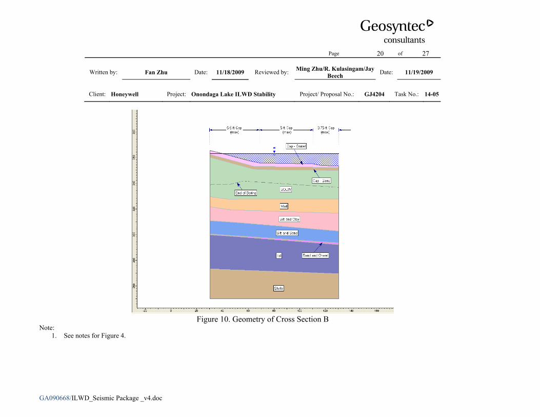
Figure 10. Geometry of Cross Section B
Note: 1. See notes for Figure 4.
Page 21 of 27
Written by: Fan Zhu Date: 11/18/2009 Reviewed by: Ming Zhu/R. Kulasingam/Jay Beech Date: 11/19/2009
Client: Honeywell Project: Onondaga Lake ILWD Stability Project/ Proposal No.: GJ4204 Task No.: 14-05
GA090668/ILWD_Seismic Package _v4.doc
Figure 11. Geometry of Cross Section C
Note: 1. See notes for Figure 4.
Page 22 of 27
Written by: Fan Zhu Date: 11/18/2009 Reviewed by: Ming Zhu/R. Kulasingam/Jay Beech Date: 11/19/2009
Client: Honeywell Project: Onondaga Lake ILWD Stability Project/ Proposal No.: GJ4204 Task No.: 14-05
GA090668/ILWD_Seismic Package _v4.doc
Figure 12. Slope Stability Analysis Result for Cross Section 2
Page 23 of 27
Written by: Fan Zhu Date: 11/18/2009 Reviewed by: Ming Zhu/R. Kulasingam/Jay Beech Date: 11/19/2009
Client: Honeywell Project: Onondaga Lake ILWD Stability Project/ Proposal No.: GJ4204 Task No.: 14-05
GA090668/ILWD_Seismic Package _v4.doc
Figure 13. Slope Stability Analysis Result for Cross Section 3
Page 24 of 27
Written by: Fan Zhu Date: 11/18/2009 Reviewed by: Ming Zhu/R. Kulasingam/Jay Beech Date: 11/19/2009
Client: Honeywell Project: Onondaga Lake ILWD Stability Project/ Proposal No.: GJ4204 Task No.: 14-05
GA090668/ILWD_Seismic Package _v4.doc
Figure 14. Slope Stability Analysis Result for Cross Section C
Page 25 of 27
Written by: Fan Zhu Date: 11/18/2009 Reviewed by: Ming Zhu/R. Kulasingam/Jay Beech Date: 11/19/2009
Client: Honeywell Project: Onondaga Lake ILWD Stability Project/ Proposal No.: GJ4204 Task No.: 14-05
GA090668/ILWD_Seismic Package _v4.doc
Attachment 1 Sensitivity Analysis
Page 26 of 27
Written by: Fan Zhu Date: 11/18/2009 Reviewed by: Ming Zhu/R. Kulasingam/Jay Beech Date: 11/19/2009
Client: Honeywell Project: Onondaga Lake ILWD Stability Project/ Proposal No.: GJ4204 Task No.: 14-05
GA090668/ILWD_Seismic Package _v4.doc
Table 1-1. Summary of Seismic Slope Stability Sensitivity Analysis Results
Cross Section
Calculated Minimum FS using Reduced Strength
of SOLW
Yield Acceleration,
ay[1]
(g)
Maximum Horizontal
Acceleration, amax (g)
ay/amax Interpolated
Displacement Range [2] (in)
2 1.02 0.0460 0.09 0.51 0.9~2.0 3 0.96 0.0425 0.09 0.47 1.1~2.2 C 0.93 0.0405 0.09 0.45 1.1~2.2
Notes: 1. The yield acceleration corresponds to the horizontal seismic coefficient that results in a calculated FS of 1.0. 2. The displacement range was interpolated using the mean and mean + standard deviation curves presented in Figure 1-1.
Page 27 of 27
Written by: Fan Zhu Date: 11/18/2009 Reviewed by: Ming Zhu/R. Kulasingam/Jay Beech Date: 11/19/2009
Client: Honeywell Project: Onondaga Lake ILWD Stability Project/ Proposal No.: GJ4204 Task No.: 14-05
GA090668/ILWD_Seismic Package _v4.doc
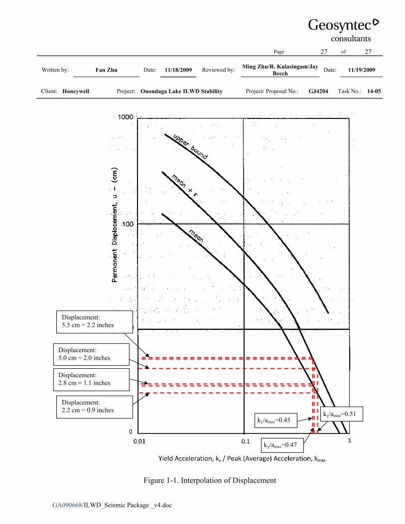
Figure 1-1. Interpolation of Displacement
Displacement: 5.0 cm = 2.0 inches
ky/amax=0.45
ky/amax=0.47
ky/amax=0.51
Displacement: 5.5 cm = 2.2 inches
Displacement: 2.8 cm = 1.1 inches
Displacement: 2.2 cm = 0.9 inches