h6 17.6 application testing of iec 61850 based systems
TRANSCRIPT

i
Application Testing of IEC 61850 Based Systems
Power System Relaying and Control Committee
Report of Working Group H6 of the
Relaying Communications and Control Subcommittee
Members of the Working Group
Charles Sufana, Chair Benton Vandiver, Vice-chair
Mark Adamiak Mike Agudo Rene Aguilar Jay Anderson
Scott Anderson Alex Apostolov
Farel Becker Gabriel Benmouyal
Oscar Bolado James Bougie
Christoph Brunner Dac-Phuoc Bui
Jason Buneo John Burger
Matthew Chan Chris Chelmecki
Mike Dood Emmanuel Duvelson
Kevin Easley Alex Ellis
Herbert Falk Didier Giarratano
Jay Gosalia Roman Graf
George Gresko John Grimm
Erich Gunther Juergen Holbach
Chris Huntley Mansour Jalali Mital Kanabar
Stan Klein Steven Kunsman
Marc Lacroix Alex Lee
Rick Liposchak Yuchen Lu
Ralph Mackiewicz Jose Mar
Deepak Maragal Aaron Martin
Bruce Muschlitz Shyam Musunuri James Niemira
Dan Nordell Mouad Oubidar
Jose Perez Dan Reckerd
Antonio Riccardo Vijay Shanmugasu
Scott Short Mark Simon
Veselin Skendzic John Tengdin Dustin Tessier Eric Thibodeau
Stephen Thompson Robert Thornton-Jones
Harsh Vardhan Jun Verzosa Don Ware
Chan Yet Wong Tracy Yuan
Mohammad Zubair

ii
ACKNOWLEDGMENTS The Working Group is truly grateful for the support of our sponsoring committee, the Power System Relaying and Control Committee and Relaying Communications and Control Subcommittee.
KEYWORDS
GOOSE, IEC 61850, Logical Node, Sampled Values, Testing, Protection, Control, Networks, Substation

iii
CONTENTS
1. INTRODUCTION ....................................................................................................... 1
1.1 Scope ............................................................................................................... 1
1.2 Summary .......................................................................................................... 1
1.3 Purpose ............................................................................................................ 1
1.4 Key Abbreviations and Acronyms ..................................................................... 1
2. INTRODUCTION TO IEC 61850 TESTING ............................................................... 3
2.1 Introduction and testing performed.................................................................... 3
2.2 Approach to a testing philosophy for GOOSE Edition 1 .................................... 4
2.3 Traditional Testing Versus Testing with IEC 61850 Logical Nodes .................... 6
2.3.1 Isolation of Entire Physical Devices (LPHD & All LN0) ............................... 8
2.3.2 Isolation of Single Logical Device (Single LLN0) ........................................ 8
2.3.3 Isolation of Nested Logical Devices (Single LLN0) ..................................... 8
3. SUBSTATION NETWORK DOCUMENTATION ........................................................ 9
3.1 Documentation of substation networks ............................................................. 9
3.1.1 Physical Documentation ........................................................................... 10
3.1.2 Logical Documentation ............................................................................. 10
4. WHAT TESTS NEED TO BE PERFORMED? ......................................................... 11
4.1 Traditional Testing .......................................................................................... 11
4.1.1 Testing GOOSE in a Substation ............................................................... 11
4.1.2 Trial Operation ......................................................................................... 13
4.1.3 Test Case: SCE C-RAS .......................................................................... 13
4.2 Methods and Tools ......................................................................................... 16
4.3 IEC 61850 GOOSE Testing - Is it a Real or Test Message? ........................... 20
4.4 Testing Network Reconfiguration Time ........................................................... 23
4.5 How to test sampled values (SV) .................................................................... 27
4.5.1 Time Reference ....................................................................................... 29
4.6 IEC 61850 Edition 2 Features Related to Testing ........................................... 31
4.6.1 Simulation ................................................................................................ 32
4.6.2 Mode and Behavior of Functions .............................................................. 34
4.6.3 Transmission of outputs and processing of Inputs .................................... 36
5. HOW TO CONNECT TO A NETWORK TO TEST IEC 61850 DEVICES ................. 38
5.1 Using VLANs as an Isolation Tool for IEC 61850 Applications ........................ 38
iv
5.2 Identify the various scenarios of IED configurations that need to be tested and how 39
5.2.1 Network Architecture Test ........................................................................ 39
5.2.2 Protection Scheme anomalies .................................................................. 40
5.2.3 Publishing and subscribing IEDs reporting capabilities ............................. 42
6. SECURITY CONSIDERATIONS FOR IEC 61850 GOOSE TESTING AFTER COMMISSIONING ........................................................................................................ 43
7. SYSTEM PERFORMANCE VALIDATION ............................................................... 45
7.1 How to test redundancy? ................................................................................ 46
7.2 What level of redundancy? ............................................................................. 48
7.3 How to establish benchmarks for performance testing? .................................. 48
8. SAMPLE CASES ..................................................................................................... 49
8.1 Sample Test Case: ......................................................................................... 49
9. CONCLUSION ........................................................................................................ 49
Fig. 1. SCE C-RAS System Components for South-of-Lugo ........................................... 14 Fig. 2. LSR Hardware ....................................................................................................... 16 Fig. 3. Conceptual Substation Ethernet LAN ................................................................... 17 Fig. 4. Example of a network analyzer software showing self-description of GOOSE message ............................................................................................................................. 19 Fig. 5. Network setup to determine switch fault instance ................................................. 24 Fig. 6. Network setup to determine network reconfiguration time ................................... 25 Fig. 7. Network Reconfiguration Time ............................................................................. 26 Fig. 8. Closed loop test of Merging Unit .......................................................................... 27 Fig. 9. Field test of merging unit using secondary injection ............................................. 28 Fig. 10. Field test of merging unit using primary injection .............................................. 29 Fig. 11. Simulation feature for selection of GOOSE message for processing .................. 33 Fig. 12. Modes and Behavior of Logical Nodes and processing of incoming data .......... 36 Fig. 13. Performance of GOOSE subscribing and publishing test ................................... 41 Fig. 14. GOOSE Performance test .................................................................................... 42 Fig. 15. Function boundary definition of known system .................................................. 46 Fig. 16. Full system architecture ....................................................................................... 46 Fig. 17. Testing of IED with SMV and hard wired interface ........................................... 47 Fig. 18. Bay or system level distributed applications testing ........................................... 48
Table 1. Behavior of Logical Nodes resulting from Modes of Hierarchical Logical Devices and Logical Nodes. ............................................................................................. 35 Table 2. Effect of Publisher mode/behavior on output and published quality information........................................................................................................................................... 37 Table 3. Effect of Subscriber mode/behavior on processing of incoming data ................ 37 Table 4. Redundancy protocols specified in IEC 62439................................................... 39

v
THIS PAGE LEFT BLANK INTENTIONALLY
1
1. INTRODUCTION
1.1 Scope
Write a report to the Institute of Electrical and Electronics Engineers (IEEE) Power System Relaying and Control Committee (PSRC) H Subcommittee on application testing of the International Electrotechnical Commission (IEC) 61850 based protection and control systems. Emphasis will be on the Generic Object Oriented Substation Event (GOOSE).
1.2 Summary
This report provides some insight into how IEC 61850 protection applications can be tested. As the reader will see, various approaches and testing concerns will be presented.
1.3 Purpose
This IEEE PSRC report is meant to provide testing methods that are applicable for IEC 61850 based protection and control systems. "Lessons Learned" from various users are presented.
1.4 Key Abbreviations and Acronyms
BPA Bonneville Power Administration
BRP Beacon Redundancy Protocol
C-RAS Centralized Remedial Action Scheme
CRP Coupled Redundancy Protocol
DHS- CCSS Department of Homeland Security – Catalog of Control Systems Security
DRP Distributed Redundancy Protocol
GOOSE Generic Object Oriented Substation Event
HSR High-availability Seamless Redundancy
IEC International Electrotechnical Commission
IEC 61850 International Standard for Communication networks and systems for power utility automation
IED Intelligent Electronic Devices
IEEE Institute of Electrical and Electronics Engineers

2
IP Internet Protocol
ISL Inter-Switch Link
LAN Local Area Network
LCCH Logical Node for Physical Communication Channel Supervision
LD Logical Device
LED Light emitting diode
LGOS Logical Node for GOOSE Subscription
LN Logical Node
LPHD Logical Node for Physical device information
LSVS Logical Node for Sampled Value Subscription
MAC Media Access Control
MIB Management Information Base
MRP Media Redundancy Protocol
NIST National Institute of Standards and Technology
NISTIR NIST Interagency Report
PAC Protection, Automation, and Control
PDU Protocol Data Unit
PRP Parallel Redundancy Protocol
PSCCC IEEE Power System Communications & Cybersecurity Committee
PSRC IEEE Power System Relaying and Control Committee
PTP Precision Time Protocol
RADIUS Remote Authentication Dial-In User Service
RAS Remedial Action Scheme
RASP Remedial Action Scheme Processors
RSTP Rapid Spanning Tree Protocol
SCE Southern California Edison

3
SCL Substation Configuration Language (also known as Substation Configuration description Language)
SMV Sampled Measured Value
STP Spanning Tree Protocol
SV Sampled Values
TCP/IP Transmission Control Protocol/Internet Protocol
UAP Unified Analytic Platform
VLAN Virtual Local Area Network
WECC Western Electricity Coordinating Council
1PPS One Pulse Per Second
2. INTRODUCTION TO IEC 61850 TESTING
2.1 Introduction and testing performed
The IEC 61850 standard defines an Ethernet based multicast protocol known as GOOSE which is based on the publisher-subscriber mechanism. GOOSE can be used for multicasting the device status, controls and measured values over an Ethernet network. The GOOSE message is a Layer 2 Ethernet-only message (no IP address). The structure of the GOOSE contains a Header that contains identification and timing information and a Data area that contains data elements as defined by the design engineer. Data elements can contain Boolean data destined to trip a breaker or initiate Breaker Failure and may also contain Analog values such as Volts, Amps, Watts, Vars, and any other analog value of interest.
Implementing an IEC 61850 based substation automation system has many advantages. Some utilities have experienced a reduction in the wiring required for protection, control, and indication. Others have lowered their equipment, design, construction, maintenance, and documentation costs. However, within these advantages lie the challenges of evaluating, troubleshooting, and maintaining these Ethernet based systems. Depending on what parts of IEC 61850 are implemented, a station based on the standard might replace the conventional hard-wired solutions with local area network solutions. This report covers some of the testing aspects for a system utilizing IEC 61850.
For the power engineer or technician who knows how to test conventional protection schemes, implementing the IEC 61850 standard requires understanding what portions of the standard are implemented as well as networking and how the two relate to each other. Where meters (e.g. digital multimeter, analog multimeter, analog panel meter, digital panel meter, IED with metering capabilities) were used to measure digital and analog quantities, an engineer or technician now needs more tools and know how to use them to

4
aid in testing, troubleshooting and maintenance activities. Examples of such tools are managed Ethernet switches being installed in the network infrastructure so that port mirroring is supported (refer to IEEE 1615 for a list of helpful managed switch features) and can be accomplished when needed to see all network traffic on a particular network segment and a network sniffer that can automatically interpret all of the protocol messages being captured for their analysis in support of testing, troubleshooting, and maintenance activities.. Where protection test sets were used to input current and voltage values, and record digital outputs, an engineer or technician now needs to be fluent with GOOSE messaging simulation software and test devices when implementing GOOSE. Where cut out devices are used to isolate IEDs, engineers and technicians now also need to understand how to put an IED in test mode and monitor the simulation bit of GOOSE messages (note, if vendors choose to implement the bit S in the GOOSE message, it is not conformant to IEC 61850-8-1 and its use may cause interoperability issues).
2.2 Approach to a testing philosophy for GOOSE Edition 1
A consideration during the initial development of your control logic in a device is the philosophy for testing GOOSE messaging. It is advantageous to consider testing the principal functionality of the IEDs using GOOSE messaging during the design phase of the overall control system of a substation. For example, it is beneficial to test the protection elements, control logic, and the response of the physical input/output (I/O) of a protective relay prior to interfacing with an integrated system. Also, test Supervisory Control and Data Acquisition (SCADA) links that are getting their data from GOOSE messaging after the GOOSE messaging is tested. This helps assure the correct configuration is in the device and hopefully give some indication as to what to expect when connected to an integrated system.
Using an approach similar to what is a common procedure when testing protective relays prior to checking the integrated SCADA link, may help with productivity and reduce risk of unnecessary outages. Testing of the logic and I/O related to GOOSE messages can be aided by utilizing spare logic variables that can be set and monitored to simulate the messages. Since Edition 1 does not provide a dedicated test mode, it is essential to configure the logic such that we have the ability to block any undesired control action, due to the receipt of GOOSE messages, as a result of the test procedure.
When testing the GOOSE messaging, consideration is typically given as how to verify the receipt of the message by the appropriate IEDs only, and not by other devices on the networks, using a procedure that minimizes the equipment that has to be isolated. During initial commissioning of isolated electrical systems or components, testing can occur with minimal risk. The philosophy is to develop control logic in the devices that will support testing of IEDs without affecting an operational system, even after future system modifications.
IEDs are configured to subscribe to GOOSE messages sent as a multicast, from specific sources. When adding a new device to an existing network using GOOSE messaging, the design of the IED logic needs to consider the impacts of adding new IEDs that may be publishing and subscribing to different GOOSE messages so that in some cases being

5
able to internally block the control output of a particular device to prevent inadvertent control output operation due to a mis-configured GOOSE subscription and/or publication. Many IEDs allow GOOSE message receipt to be programmed in the IED to a front panel LED, sequence of event point, or other point exercising care when the number of these points is limited. This programming is not only helpful for testing but can also be helpful when an event occurs that is related to the GOOSE message being monitored. Testing of responses to GOOSE messages may require the programming of test-switch like functionality from hard-wired schemes into the scheme logic. One approach of accomplishing this is to dedicate a control button (or test switch) on each device for GOOSE Test that can be used to set a non-volatile latch and interrupt the portion of the control logic that responds to a GOOSE message, but not inhibiting the remaining logic or method of monitoring receipt of the GOOSE message. There might be an advantage in segregating control related to GOOSE or any other integrated network control system from other control logic.
Programming an IEC 61850 IED to use an external push button acting as a “GOOSE Test” button to change the mode and behavior of the IED can facilitate testing. This method could confirm that the proper breaker opens or to trigger another GOOSE message that a network analyzer can see, or perhaps turn on a light on another IED as part of a demonstration. The usage will be limited only by the user's imagination.
Knowing change is a part of life, consideration needs to be given to the design of the logic as to how one will address future expansion of one's integrated control system. Here is a simple example:
Consider testing a distribution substation that currently uses GOOSE messaging. At this existing station it is desired to add an additional circuit, associated breaker, and relays. For this existing installation, the following is assumed: GOOSE messaging has been implemented, the GOOSE test buttons and related logic are working properly, and the correct configuration is loaded.
As a start consider testing the integrity of the network, configuration of the IEDs and integrated control in a live substation. Does the design:
• Provide isolation from the GOOSE message from actually tripping devices or controlling elements in the IED that can result in an outage?
• Create a sequence of events log in IEDs, subscribing to the GOOSE message, that a GOOSE message was received and interpreted?
• Permit bench testing of the IEDs integrated control logic and basic functionality?
• Utilize standardized configuration architecture and documentation? Verify the design and test for the receipt of a specific GOOSE message, understand what variable in the IED is to be set and if the resulting action is as expected. As a pre-check for testing the IED connected to the network; this

6
is particularly valuable when determining if the GOOSE test button is working.
• Have standardized architecture that has been designed to account for additional devices being added to the control system without major reconfiguring of existing devices, like the addition of an additional feeder breaker? Having the architecture be as much Plug and Play as possible can help. It would be much easier to change an existing system by just plugging in a new IED and then reprogramming a few settings than to actually have to rewire and locally reprogram each relay individually.
Prior to connecting new IEDs to a substation network, it is assumed that the protective functions have been programmed and tested, that the physical I/O is functioning properly, and if there is a GOOSE test button used for blocking; that it does indeed block any critical control from being exercised from receipt of a GOOSE message. Knowing that circuits are to be added to the substation, it would be helpful if the substation network configuration allowed for the ability for the existing relays to subscribe to messages from an additional set of feeder relays. If not, then configuration changes to the appropriate existing IEDs will have to be made. Once it is believed the IEDs are all set to subscribe to GOOSE messages from the new IED, place all appropriate IEDs into the GOOSE test mode and then connect the new IED to the network to prevent inadvertent operation.
The first application to be tested is the GOOSE test button of the new relay. Once the GOOSE test button of the new relay has been pressed, then the other relays can confirm receiving a GOOSE message from the new relay and have interpreted it as a request to go to GOOSE Test Mode. The same can be tested in reverse to assure the new relay is properly subscribing to the existing relays. Then other GOOSE messages can be tested, like simulation of a differential trip from the existing differential relay element, verifying the GOOSE message is received and interpreted properly by the new relay. "Then as a final check, reset the new relay from the GOOSE trip mode and do a final trip check to the new breaker.
A more desirable method is to use the Edition 2 features as described in clause 4.6 of this report.
2.3 Traditional Testing Versus Testing with IEC 61850 Logical Nodes
With traditional testing it is common that when an IED was taken out of service for testing, the entire physical device was isolated including all the embedded functionalities. This is done by placing the entire IED into test mode, in conjunction with physically isolating the hard-wired I/O using test switches, test blocks, etc.
IEC 61850 provides flexibility because an IEC 61850 IED hosts multiple logical devices (LD) (e.g. protection, control, metering, etc.) that could be isolated whereas traditional testing isolates ALL of these logical functionalities. IEC 61850 allows each logical device - and any nested logical devices - to be individually isolated and tested if needed.
7
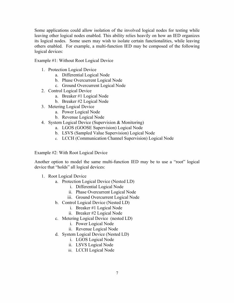
Some applications could allow isolation of the involved logical nodes for testing while leaving other logical nodes enabled. This ability relies heavily on how an IED organizes its logical nodes. Some users may wish to isolate certain functionalities, while leaving others enabled. For example, a multi-function IED may be composed of the following logical devices:
Example #1: Without Root Logical Device
1. Protection Logical Device a. Differential Logical Node b. Phase Overcurrent Logical Node c. Ground Overcurrent Logical Node
2. Control Logical Device a. Breaker #1 Logical Node b. Breaker #2 Logical Node
3. Metering Logical Device a. Power Logical Node b. Revenue Logical Node
4. System Logical Device (Supervision & Monitoring) a. LGOS (GOOSE Supervision) Logical Node b. LSVS (Sampled Value Supervision) Logical Node c. LCCH (Communication Channel Supervision) Logical Node
Example #2: With Root Logical Device
Another option to model the same multi-function IED may be to use a “root” logical device that “holds” all logical devices:
1. Root Logical Device a. Protection Logical Device (Nested LD)
i. Differential Logical Node ii. Phase Overcurrent Logical Node
iii. Ground Overcurrent Logical Node b. Control Logical Device (Nested LD)
i. Breaker #1 Logical Node ii. Breaker #2 Logical Node
c. Metering Logical Device (nested LD) i. Power Logical Node
ii. Revenue Logical Node d. System Logical Device (Nested LD)
i. LGOS Logical Node ii. LSVS Logical Node iii. LCCH Logical Node

8
2.3.1 Isolation of Entire Physical Devices (LPHD & All LN0)
IEC 61850 provides the LPHD logical node that contains the common information for that specific physical IED. The modeling of the LPHD chosen by a vendor in its implementation is important to understand from a testing perspective. Users can emulate their current testing practices by placing the entire physical IED under test mode, including all logical devices. This is accomplished by setting the mode data attribute to test mode for all logical devices, each one having their own LLN0. LLN0 represents the common information for that particular logical device. For example, the mode of LLN0 is used to control the mode for the associated logical device, and as a result the mode of every logical node that is associated with that particular logical device.
For in-service applications where the IED needs to process both the real-time signals from the in-service equipment, as well as simulated signals from a test set, the use of Test-Blocked and On-Blocked test modes are required. Furthermore, the LPHD sim data object is asserted, and the IED will process both the real-time GOOSE signals as well as the simulated GOOSE signals. Please note that these simulation features are only applicable to GOOSE messages as described elsewhere in this report.
Using Example #1 shown above, this would equate to isolating each individual logical device for the Protection, Control and Metering, all of which are being placed in test mode via LLN0.
Using Example #2 shown above, this equates to setting the test mode of the LLN0 of the “root” logical device. The nested logical devices will inherit this test mode from the root logical device.
2.3.2 Isolation of Single Logical Device (Single LLN0)
IEC 61850 provides the capability for an IED to take a “partial outage” to the IED by leaving some functionalities enabled within the IED while disabling others. For example, IEDs may allow the isolation of the protection logical device (e.g. during the IED protection testing) and leave the control logical device enabled so that remote/local operation of the breaker is still possible, etc. This is achieved by only setting the mode data object for the desired logical device, which is done via the associated LLN0. If there is more than one LD in an IED, then use the LD hierarchy in Edition 2.
Using Example #1 shown above, this would equate to placing the protection logical device in test mode and leaving the other logical devices in service. In this example ALL protection logical nodes under this particular logical device would be isolated.
2.3.3 Isolation of Nested Logical Devices (Single LLN0)
IEC 61850 supports a hierarchy of logical devices. In this case, a given logical device may have child logical devices, which are nested underneath it.
If all logical devices were nested under a single parent logical device (e.g. root LD) (see Example #2), this would limit the flexibility to isolate each individual LD. In this case the

9
root logical device defines the test mode, including the data objects 'Mod', 'Health' and 'NamPlt' that are inherited from the root LD. This allows all descending logical node instances to "inherit" the appropriate data values without need to repeat them.
If added flexibility is required, a root LD is not required, and each individual nested logical device can be isolated on its own. Using Example #1 shown above, this could equate to isolating a single protection logical device while leaving the other protection logical devices in service. For example, isolating the differential protection element but leaving the ground overcurrent element enabled due to personnel working in close proximity of the apparatus, etc. This is adding another level of flexibility to what was described in Section 2.3.2.
3. SUBSTATION NETWORK DOCUMENTATION
3.1 Documentation of substation networks
Networks are designed to transmit large amount of data to multiple devices using multiple protocols. It supports high speed communications between these devices and can span great distances. From a hardware point of view, physical cabling of Ethernet networks typically provides either one device connection or two device connections when redundancy is used. Ethernet networks support communications using multiple protocols over the same communication cable, where each device is connected to one or more switches and may be connected to a router depending upon the logical design of the physical network. This can lead to a very complex communication system, both physically and logically. Good documentation is required of these systems so that the user can determine exactly how the devices are interconnected, both physically and logically.
The IEEE PSRC has a report entitled "Schematic Representation of Power System Relaying" that discusses common practices in the representation of protection and control relaying.1 Clauses 6.3 (DC Schematics and the Microprocessor Relay), 6.4 (DC Schematics and IEC 61850 Station Bus), and 8.3.1 (Internal Communications) highlight the challenge of schematic representation and communication network design when microprocessor relays are used.
The report describes that IEC 61850 GOOSE messages are best represented in a point-to-point or spreadsheet format. Refer to the report for the full discussion.
At the 2017 Texas A&M Protective Relaying Conference, a paper entitled "If You Cannot Test It, You Cannot Use It – IEC 61850 GOOSE System Designed With Testing
1 Schematic Representation of Power System Relaying, A report to the Relaying Practices Subcommittee I, Power System Relaying Committee, Prepared by Working Group I5, May 13, 2014, [Online]. Available: http://www.pes-psrc.org/kb/published/reports/IEEE_I5_Schematic_Approved_Final.pdf

10
in Mind" was presented highlighting a process that Consolidated Edison is following.2 This paper provides procedures and guidelines for use with GOOSE protection schemes and written by a Consolidated Edison and Schweitzer Engineering Laboratories author team.
The IEEE PSCCC has a report entitled "Application of Ethernet Networking Devices Used for Protection and Control Applications in Electric Power Substations" which highlights the need for proper documentation3. The report points out that good documentation is needed; especially for disaster recovery.
3.1.1 Physical Documentation
Physical documentation of the communication networks needs to include both wired and wireless connections (note that IEC 61850 presently does not include a wireless specification). Interfaces to external networks need to be documented but the details of those external networks do not necessarily need to be included with the network documentation. The information that needs to be included are the actual devices, converters (if used, e.g. media converter, protocol converter), type of interconnection (wired vs wireless, copper vs fiber), and cable routing. This documentation does not have to be done on one document. The physical location and cable routing can be in one document while a system interconnection can be on another drawing.
3.1.2 Logical Documentation
Logical documentation is used to show how the different devices are logically connected to each other via ports and services (which typically includes protocols), along with other logical concepts such as virtual LANs, subnets, and IP addresses. Physical networks are not shown on a logical network drawing. A logical network drawing will show GOOSE messaging along with all other data flows used on the network. A logical network diagram may include one or more of the following types of data flows: SCADA, protection data flows, engineering access (both local and remote), and local control systems using a variety of other protocols, ports, and services. This documentation can be helpful in preparing for and conducting GOOSE testing because it shows what other data flows are on the physical network and what could possibly be disturbed by specific tests that could disturb the logical network flows. For example, if GOOSE testing includes testing the network for proper handling of a GOOSE message flood (either on accident or for other reasons), other data flows could be disturbed. Another example is when GOOSE
2 If You Cannot Test It, You Cannot Use It – IEC 61850 GOOSE System Designed With Testing in Mind, D. Burkart, W. Edwards, A. Atalay, and S. Snuggs, Presented at the 2017 Texas A&M Protective Relaying Conference, [Online]. Available: https://selinc.com/api/download/119348/ 3 Application of Ethernet Networking Devices Used for Protection and Control Applications in Electric Power Substations, Subcommittee P, IEEE PSCCC, Prepared by Working Group P6, [Online]. Available: http://sites.ieee.org/pes-pscc/files/2018/09/PSCCC-WG-P6-Report-Ethernet-Networking-R1-final-091217.pdf
11
testing disturbs the network infrastructure by unplugging Ethernet cables, the logical network drawing will show what other communication services and protocols will be disturbed.
4. WHAT TESTS NEED TO BE PERFORMED?
4.1 Traditional Testing
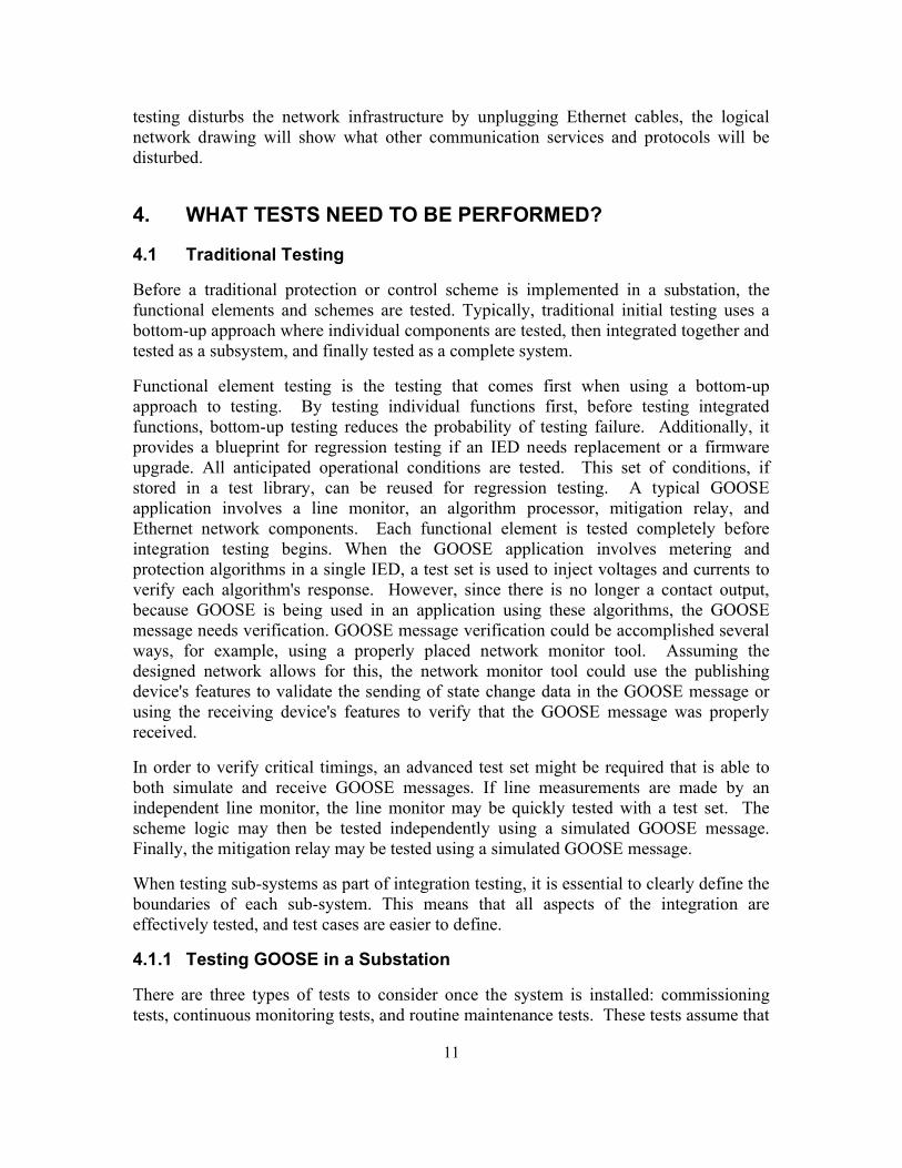
Before a traditional protection or control scheme is implemented in a substation, the functional elements and schemes are tested. Typically, traditional initial testing uses a bottom-up approach where individual components are tested, then integrated together and tested as a subsystem, and finally tested as a complete system.
Functional element testing is the testing that comes first when using a bottom-up approach to testing. By testing individual functions first, before testing integrated functions, bottom-up testing reduces the probability of testing failure. Additionally, it provides a blueprint for regression testing if an IED needs replacement or a firmware upgrade. All anticipated operational conditions are tested. This set of conditions, if stored in a test library, can be reused for regression testing. A typical GOOSE application involves a line monitor, an algorithm processor, mitigation relay, and Ethernet network components. Each functional element is tested completely before integration testing begins. When the GOOSE application involves metering and protection algorithms in a single IED, a test set is used to inject voltages and currents to verify each algorithm's response. However, since there is no longer a contact output, because GOOSE is being used in an application using these algorithms, the GOOSE message needs verification. GOOSE message verification could be accomplished several ways, for example, using a properly placed network monitor tool. Assuming the designed network allows for this, the network monitor tool could use the publishing device's features to validate the sending of state change data in the GOOSE message or using the receiving device's features to verify that the GOOSE message was properly received.
In order to verify critical timings, an advanced test set might be required that is able to both simulate and receive GOOSE messages. If line measurements are made by an independent line monitor, the line monitor may be quickly tested with a test set. The scheme logic may then be tested independently using a simulated GOOSE message. Finally, the mitigation relay may be tested using a simulated GOOSE message.
When testing sub-systems as part of integration testing, it is essential to clearly define the boundaries of each sub-system. This means that all aspects of the integration are effectively tested, and test cases are easier to define.
4.1.1 Testing GOOSE in a Substation
There are three types of tests to consider once the system is installed: commissioning tests, continuous monitoring tests, and routine maintenance tests. These tests assume that

12
all functions have been subject to acceptance testing. This limits test cases to those that verify device health, correct wiring, and correct settings /configuration.
Commissioning tests are performed when the scheme is first installed in a substation. Since individual components have already been validated, use a top down approach for the commissioning tests. If the system is sufficiently complex, individual subsystems may be commissioned first, but final tests need to use an end-to-end approach to prove the complete scheme will operate correctly. What this means is evaluate the scheme as close to normal operation as possible for the final commissioning tests. This may mean a small number of tests where voltages and currents are injected to verify that a disconnected relay output closes. Additionally, if the onsite system has any significant differences from the initially evaluated system, some functional or integration tests may need to be repeated. For instance, physical media type or lengths may cause additional delays that require system performance to be re-evaluated. If multiple schemes overlap, take additional care to not only isolate the scheme under test, but to also verify that overlapping schemes are not affected. If possible, the schemes are to remain in operation, but with care taken in all circumstances to prevent false operation. The SCE paper "Standardized Testing Philosophies and Methods - How they are applied to the SCE C-RAS System" discusses in chapter 9 this issue.4
Continuous monitoring tests allow detection of system problems in real time. Self-monitoring performed by individual IEDs can uncover failed components; integration of this information with IEC 61850 can improve notification time and even facilitate fast automated responses. In addition to providing IED alarms like more traditional SCADA systems, IEC 61850 provides data quality bits that indicate whether the data may be used. The GOOSE messaging protocol also provides a mechanism to detect damaged networks and source IEDs. GOOSE messages are primarily sent upon change of state. If there is no change of state (no change in payload data), then this mechanism verifies connectivity by periodically sending GOOSE messages. If a destination relay receives data that is marked as bad or questionable, or it is no longer receiving GOOSE messages from the source, it could alarm a system operator and potentially take an automated action. A well-designed protection or control scheme will account for GOOSE messages that are either missing or contain questionable data. Path performance testing may also be tested continuously either by periodic ping tests, where devices on a network path are configured to send instantaneous response packets to measure round trip time, or by real time analysis of sequence of events files if devices are time synchronized.
Routine maintenance tests can potentially be simplified by the continuous monitoring of GOOSE messages and data, however, each system might need to be evaluated to determine the benefit of testing each component of the system. The SCE C-RAS system discussed below makes use of continuous monitoring and has been beneficial to the company.
4 Standardized Testing Philosophies and Methods: How they are applied to the SCE C-RAS System, whitepaper, Southern California Edison, Oct. 2008.

13
4.1.2 Trial Operation
Trial operation is observation of the scheme in an operational system prior to allowing the scheme to affect the system. The use of GOOSE messaging may affect the decision to employ a trial of the scheme if its inclusion significantly affects the complexity of the system that is being implemented, or if communications equipment and IEDs are largely untested in the field.
4.1.3 Test Case: SCE C-RAS
SCE has utilized IEC 61850 to implement a Centralized Remedial Action Scheme (C-RAS).5 According to the Western Electricity Coordinating Council – Remedial Action Scheme Design Guide6, “RAS sense abnormal system conditions and (often) take pre-determined or pre-designed action to prevent those conditions from escalating into major system disturbances. RAS actions minimize equipment damage and prevent cascading outages, uncontrolled loss of generation, and interruptions to customer electric service.” In a C-RAS, the processing of data and decision making is performed at a central location. IEC 61850 can be used to implement a C-RAS that reduces the amount of hardware required over a traditional RAS while maintaining reliability and security.
5 Standardized Testing Philosophies and Methods: How they are applied to the SCE C-RAS System, whitepaper, Southern California Edison, Oct. 2008. 6 Western Electricity Coordinating Council – Remedial Action Scheme Design Guide, November 28, 2006, https://www.wecc.org/Reliability/RWG RAS Design Guide _ Final.pdf

14
Fig. 1. SCE C-RAS System Components for South-of-Lugo
Fig. 1 shows a portion of the SCE C-RAS system. Line Monitors provide status and analog information for each bus. Fig. 1 shows a GOOSE message going through a Router. In as much as GOOSE is a Layer 2 message, it has no Internet Protocol (IP) address on which the router can act. The Routers in CRAS are programmed to "detect" Layer 2 messages and to map them into Layer 3 messages with IP addresses. Routable GOOSE (R-GOOSE) eliminates the need for field configuration of routers to pass GOOSE messages and implements true IP Multicast (the router mapping is only point-to-point). In a centralized location, the data is conditioned and fed to triply-redundant RAS processors (RASP). Each RASP independently computes a decision and sends its decision to the mitigation processor. The mitigation processor then performs an action based on the majority decision from the RASPs. The SCE C-RAS implementation contains two systems “A” and “B” that are completely independent except for the mitigation breakers. As noted in [SCE 2008], “The system for testing a C-RAS system

15
varies depending upon the maturity of the entire system.” SCE proposes a staged, bottom up approach combined with trial operation.
The first stage of the SCE testing approach is the deployment of a few RAS for initial testing. As this initial scheme is deployed each function of the RAS is tested to verify operation. The line monitors are tested to verify they properly convert line conditions to GOOSE messages. The network connectivity to the C-RASP is then tested by publishing GOOSE messages in the substation network and verifying that they are received at the C-RASP. Mitigation processors are next tested by publishing GOOSE messages in the substation network and verifying the mitigation response. Next the network connectivity between the C-RASP and mitigation processor is tested by publishing GOOSE messages in the C-RASP network and verifying that they are correctly routed to the mitigation processors network. The mitigation processors might also need to be tested to verify that they do not operate when test messages are sent. Performance (Latency) testing of data transmission is also being performed.
The C-RASPs may now be thoroughly tested by publishing GOOSE messages locally and monitoring test GOOSE messages from the C-RASP. Each individual scheme may be tested through this method of publishing GOOSE messages, but there is no longer any need to inject a signal into every combination of RASPs.
After each subsystem is tested, a small number of end-to-end tests can be run where signals are directly injected into the low-level input side of the line monitor and operation of the mitigation processor is confirmed. Only full end-to-end testing of new/modified RASs occur in the operational system. The system is designed to allow for this so that the availability of existing RASs is not impacted by the testing of a new RAS.
The final part of the first stage is “soak test” or trial operation. For this test, the scheme is running, but mitigation outputs are disabled. The trial continues until a suitable number of events are logged. Each new RAS has a "burn-in" time that is determined on a case by case basis, but it has typically been greater than 1000 hours. A detailed analysis of each event is performed, and any discrepancies resolved. The initial C-RAS schemes have been in operation since March 2016.
The next stage of C-RAS deployment is the addition or modification of schemes without the addition of any new line monitors or mitigation processors. The new scheme is initially tested offline. The scheme is modeled in the C-RASP, which provides a list of inputs and outputs. One of the C-RASPs is detached from the network and put into test mode. During the quality assurance stage, and upon installation of new RAS/Equipment in the operational system, GOOSE messages that simulate various scenarios are injected to evaluate performance of the C-RASP scheme. Simulated end-to-end tests are now conducted by placing the C-RASP into test mode. When in test mode the C-RASP Instrumentation Conditioner only accepts GOOSE messages marked with the test bit. The C-RASP will transmit only test GOOSE messages and the mitigation processor will not activate the mitigation outputs based on a GOOSE message marked with the test bit. The SCE mitigation equipment also includes a Latching Switch Relay (LSR) mode that disconnects the physical breaker trip coil and connects a similarly sized breaker coil

16
simulation resistor for use during the test period (Fig. 2). The mitigation processor will log the event so that it may additionally be verified using logs. Each C-RASP is verified using this scheme. From a GOOSE perspective, only testing of the additional C-RAS is needed. Additionally, a complete end-to-end test is not re-run in the operational system. Routine maintenance testing is performed yearly including end-to-end tests previously described.
Fig. 2. LSR Hardware
The third stage C-RAS deployment is an addition of new line monitors or mitigation relays. This stage can be tested using a combination of methods from stages one and two. New line monitors and mitigation relays are tested using initial methods from stage one, but those existing do not require thorough retesting. New schemes can each be thoroughly tested locally at the C-RAS, but only a smaller number of end-to-end tests are required. A few real signal injection tests may be required for quality assurance purposes.
4.2 Methods and Tools
For the testing of IEC 61850 applications, specialized tools and equipment are suggested to adequately verify the proper operation of the applications relying on GOOSE messaging. Fig. 3 shows a conceptualization of a substation connected via a Local Area Network (LAN). In this case, all IEDs are redundantly connected to Ethernet switches.

17
The firewall indicates the demarcation point of the Electronic Security Perimeter and may be logical or physical. For testing, it may not be existing but is tested as part of the suite of tests. To begin testing a substation of this type, there are several tools that become necessary to verify the integrity of the substation network and the performance of the IEDs.
Fig. 3. Conceptual Substation Ethernet LAN
Fig. 3 shows a conceptual substation Ethernet LAN. The modern switchgear may refer to substation equipment such as circuit breakers and disconnect switches that can be controlled via GOOSE messages. The digital CT/VTs may refer to conventional instrument transformers or optical CT/VTs that can be connected to a merging unit that forwards sampled values over the Ethernet LAN. The LAN in Figure 3 shows both the station bus and process bus on the same switch. Also note that in IEC 61850 90-4, it is suggested that the process bus and station bus be separated. In instances where the station bus and process bus are on the same LAN, it can be for applications such as busbar protection and phasor measurement. A relay test set that is capable of publishing/subscribing to GOOSE messages onto the network is suggested. It may also be capable of publishing/subscribing to sampled value waveforms.

18
Fig. 3 shows a relay test set that is computer controlled. The test set is connected directly into the substation Ethernet LAN. As shown, the relay test set has the function of forwarding GOOSE and SV traffic to the personal computer (PC) to prevent its direct access to the substation Ethernet LAN while still enabling any access to the relay test set to be monitored and logged as required.
As shown, the test set injects sampled value voltage and current quantities into the process bus to elicit a response in the form of a GOOSE message from one or several IEDs as configured to support the IEC 61850 application(s) being implemented. The test set may also have the ability to produce analog values that can be fed to a relay or merging unit depending on the requirements.
In this IEC 61850 application, the test set simulates fault quantities and the IEDs publish GOOSE messages with state changes that indicate the time taken to change state when compared to the relay test set's simulated fault. When the test set publishes GOOSE messages to the network, it may have the ability to enable the test bit in that particular GOOSE message depending on the user’s requirements. Note that is what the SCE C-RAS system is using since it is Edition 1 based. For Edition 2 systems, when the test set publishes GOOSE messages, it has the ability to enable the S (simulation) bit in the particular GOOSE message to be compliant with IEC 61850-8-1.
Network analyzers (in any combination of hardware and/or software) are used in testing an IEC 61850 substation that implements GOOSE and SV messaging. Typical network analyzer software captures the substation Ethernet LAN traffic in real time and, when conformant with IEC 61850 protocols and services, can interpret the GOOSE and/or the SV messages on the network. The self-description of the GOOSE message could be viewable to the tester as shown in Fig. 4. As a testing tool the network analyzer software allows the user to identify possible inconsistencies between the SCL file and what is actually on the network.

19
Fig. 4. Example of a network analyzer software showing self-description of GOOSE message
The analyzer software has the ability to record and playback traffic on a substation network. Depending upon the IEC 61850 application performance requirements, a network analyzer connected to IEDs publishing and subscribing to GOOSE messages supporting each application in use can be used to measure application performance specifications as defined for the application or by IEC 61850-5. A network analyzer may also be able to increase the amount of traffic on the substation Ethernet LAN in order to observe each IED's performance under increasing network traffic, such as MMS reports not being issued as specified, slower response than specified to non-IEC 61850 functionality such as engineering access, etc.
A network analyzer capable of simulating GOOSE messages may be needed to test the behavior of an IED to GOOSE messages external to the substation (e.g., breaker failure, transfer trip, etc.) and even internally to the substation (e.g., when the whole substation is unavailable for testing and some IEDs need to be simulated).When evaluating the use of a network analyzer for testing purposes, carefully consider all factors in making a selection, such as features (a few were previously described), ability to properly decode

20
the associated messages (e.g., GOOSE, SV), and ability to properly time stamp the messages to determine performance.
Any GOOSE testing is performed on the designed Ethernet LAN. If it is impossible to perform GOOSE message testing on the designed network, it is possible to use an existing Ethernet LAN provided the VLANs are appropriately set up to isolate the GOOSE traffic from the existing traffic and GOOSE priority tags are followed as designed. Precautions to avoid corrupting the existing Ethernet LAN need to be employed before performing GOOSE testing on existing Ethernet LANs. Conditions for LAN substation testing require competent personnel in the fields of computer networking as well as power system protection. There are common pitfalls that can occur in which an inexperienced protection or automation engineer can fall victim. Stripping of VLAN tags from computer ports running a network analyzer is an example of a common problem during GOOSE testing that may be easily remedied by an experienced network professional. The default settings on a typical switch will automatically strip off VLAN tags - unless there is a trunk port on the switch - in this case, the tags are transmitted. When an Ethernet frame with a VLAN tag enters a PC, the PC hardware may strip the tag before sending it to the network protocol analyzer software running on the PC. However, this may be controllable via a setting in the computer's Ethernet controller.
The GOOSE testing performed on a system after commissioning may be limited to when any new changes are made on the system or when troubleshooting is necessary. These changes may include an update to the logic scheme, or the replacement of an IED or Ethernet switch. Routine maintenance may be limited to the discretion of the network owner. Troubleshooting may require testing and/or network capture activities to determine the cause of GOOSE communication failure.
4.3 IEC 61850 GOOSE Testing - Is it a Real or Test Message?
Protection applications relying on GOOSE messages are akin to sending a hard-wired trip signal from an electromechanical, solid state relay, or microprocessor relay, via discrete wiring perhaps a test switch, to the intended device which is usually a circuit breaker but with a modern twist. GOOSE is not a hard-wired type of signal like the electromechanical world, and therein lies part of the challenge.
Testing of the hardwired trip signal may occur as follows: The relay tester could inject volts and amps into the relay to the point where the relay operates and trips the breaker, or the tester might manually produce a trip signal. It is typically easy to trace the wiring to observe the trip path being exercised by the testing. It goes directly from point A (the relay) to point B (a circuit breaker or aux relay) and a test switch would be used to prevent the signal from getting through when a test is being performed. Only by opening the test switch was the signal prevented from reaching point B. It is uncommon to perform a continuity check on the hard-wired path before testing the trip and only if the trip fails is such a test typically run. During testing there is no confirmation of the trip path before the trip signal is sent and certainly during normal operation this does not occur.

21
GOOSE is a multicast message that goes from point A (the publisher, e.g. a relay) to one or more point Bs (the subscribers) via an Ethernet network (could be LAN or WAN). Through the use of VLANs, the GOOSE message is only delivered to those ports on the switch that have been programmed to receive the published VLAN message. Additionally, publish-subscribe members of a GOOSE message are defined in the SCL. With GOOSE, the use of test or simulation data is controlled by status information in the GOOSE message and the mode of the device receiving the message.
This leads to the question- while doing testing, is a GOOSE message a "real" message that can be used for operations or is it a test message that can be used for testing? A test GOOSE message is one in which the data in the GOOSE message has a data quality equal to test. A device that is in test mode or test/blocked mode is only supposed to produce data with its data quality set to test. Therefore, any message with data that has a quality equal to test can be considered a test message coming from a device with one or more of the Logical Nodes and Logical Devices in that device in test mode.
Clause 4.6 has additional guidance for GOOSE testing with simulated data when IEC 61850 Edition 2 is used. In IEC 61850 Edition 2, a Simulation bit is defined which indicates that the message is being sent from a simulation device. There is also a simulation mode for the devices. When a device is in simulation mode it means that the device processes simulated data if any simulated data is present. Once the device is in simulation mode and it detects the presence of simulated data, it then processes the simulated data instead of any non-simulated data that is also being received. When a device is taken out of simulation mode, it then would start processing non-simulated data when it receives non-simulated data. Thus, the device’s simulation mode setting defines whether the device should process simulated data produced by a simulator or “real” non-simulated data provided by other devices in the system. Run the last test using non-simulated data to avoid differences in behavior between the simulated and non-simulated “real” data from devices. A simulated GOOSE might indicate that the system worked perfectly. But, if a real trip were to occur, the “real” GOOSE might not initiate the proper actions having never been tested.
For a live test with non-simulated real GOOSE messages, and depending upon the application, each subscribing device that accepts an incoming GOOSE message to initiate control operations needs either a “virtual test switch” or an actual test switch if a hardwired output is operated during control operations. IEC 61850 defines a method for implementing a “virtual test switch” by allowing the device to be put into a test mode for testing. The IEC 61850 test mode is independent and separate from the simulation mode. A device can be in simulation mode and not be in test mode.
There are several modes of behavior for IEC 61850 devices as described in

22
Table 1.
The modes discussed in this section are:
1) test/blocked
2) test
The tester can set the mode in the receiving devices by changing the mode of the devices to “test” or “test/blocked”. This is done by changing the Mod attribute in the LLN0 Logical Node in the Logical Device being tested or, if the device has a “Root Logical Device”, changing the Mod attribute in the LLN0 Logical Node in the Root Logical Device which would put all Logical Devices within that physical device into test mode.
When in either test or test/blocked mode, the receiving relays will process GOOSE messages containing data where the data quality validity is GOOD and with a q.test (q = quality) bit set to either TRUE or FALSE. If the q.test bit is set to TRUE it means the data produced by the device is in test or test/blocked mode. Any receiving relays that are in either test or test/blocked mode will only produce data that q.test set to TRUE, but they will operate on q.test being TRUE or FALSE if the validity is GOOD. The difference between test and test/blocked is if the receiving device is in test/blocked mode, reception of valid GOOSE messages would be processed but the device will not produce any control signals. Of course, the ultimate test would be to actually act on the received GOOSE message and send the control signals out. The tester will need to be alert as there could be numerous devices primed to operate based on GOOSE data produced that have q.test equal to FALSE. The tester will need to remember to set everything back to normal so that the devices can properly operate if a real event were to occur that causes a state transition in the GOOSE message.
The bookkeeping for a particular test may be extensive in nature. The tester typically has a list of devices to “disable” and that list could be pretty large, perhaps much larger than in the electromechanical paradigm. Once a particular test is performed, this list assists in returning the relays' settings back to normal. It could get to be somewhat time consuming but necessary to assure proper operation.
The efficiency of testing in IEC 61850 based substation protection and control systems is improved through testing automation. During the engineering of the system testing specialists design test plans that include multiple test modules required for the functional testing of the protection IEDs. The test plan includes IEC 61850 related configuration modules that define the mode of a single or multiple test objects at the beginning of the test and reset it back to the normal operating mode after the test is complete.
The change of mode is achieved using IEC 61850 client/server communications supported by the testing tools. This allows a flexible approach to the maintenance testing of IEC 61850 based substations and is more secure, since the testing tool can verify the change of mode of the test object before and after the execution of the test.

23
4.4 Testing Network Reconfiguration Time
The network reconfiguration time is defined as the total time necessary to reconfigure the network due to a topology change caused by the failure of a cable, switch, switch link (e.g., SFP module), and device link (e.g., SFP module) and is different for networks implementing RSTP, PRP, and/or HSR in any combination. Managed Ethernet switches utilize a form of RSTP as a loop avoidance protocol that will reconfigure the network topology with the failure of the active side of a loop. It is important to understand the version of RSTP the switches utilize. The version type can have a drastic effect on the total reconfiguration time. There have been many versions of STP such as IEEE 802.1D STP, IEEE 802.1W-RSTP, and IEEE 802.1D-2004. The standard STP has a reconfiguration time in the order of seconds, whereas the RSTP 802.1W typical reconfiguration times can range from a few seconds to hundreds of milliseconds. IEEE 802.1D-2004 has reconfiguration times which range in the order of a few milliseconds per switch. Proprietary extensions to RSTP exist that have lowered the reconfiguration times, however, this does require a single vendor application. Keep in mind that if various vendors are used to construct the network, the reconfiguration time will be determined by the slowest interoperable form of STP or RSTP being utilized by the switches. This is due to the switches' compatibility with older versions of the STP or RSTP. Another factor to consider when determining the network reconfiguration time is the size and topology of the network. Larger networks tend to have longer reconfiguration times compared to smaller networks. The reconfiguration time is a function of the total number of switches in the network.
A simple ring network will be used as an example to determine the network reconfiguration time due to a failure of the root bridge. Due to the way RSTP works, the failure of the root bridge represents the worst-case scenario for network reconfiguration. In this example, the switch configuration has the RSTP protocol enabled (this is not a proprietary version).
Determine Switch Fault Instance
An important factor to know before the network reconfiguration time can be measured is to determine switch dead time. Even though power is removed, the internal circuitry still remains powered and the switch is still able to perform its functions until the power fully collapses. To determine this time a simple network is setup as shown below in Fig. 5.

24
Fig. 5. Network setup to determine switch fault instance
The network is configured such that SW1 is the root bridge, which is achieved by programing the switch's bridge ID to a smaller value compared to the other switches. Connect the test set to one of the end switches and configure the port as an edge port. The relay (or any device) is connected to the other end switch thru an edge port. Wire the power to the switch via a binary output on the test set. This provides the control necessary to determine the failure time of the switch. Once the test-set up is complete, select an arbitrary failure time to start the test. A reasonable starting value could be 250 milliseconds. The test quantities are applied via a state sequencer consisting of three states. The states will be pre-fault, fault, and post fault. The test set and relay are configured such that the test set is subscribing to the GOOSE message being published by the relay. If the GOOSE message is detected, lower the failure time by 1 millisecond and continue until the GOOSE message is not detected by the test set. This time represents the amount of time needed for the electronics in the switch to completely power down. At this instant, the network will detect a switch failure and will begin the reconfiguration of the network.
25
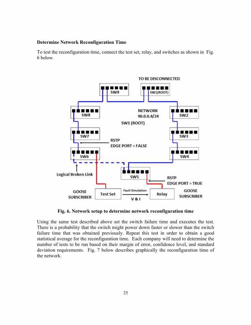
Determine Network Reconfiguration Time
To test the reconfiguration time, connect the test set, relay, and switches as shown in Fig. 6 below.
Fig. 6. Network setup to determine network reconfiguration time
Using the same test described above set the switch failure time and executes the test. There is a probability that the switch might power down faster or slower than the switch failure time that was obtained previously. Repeat this test in order to obtain a good statistical average for the reconfiguration time. Each company will need to determine the number of tests to be run based on their margin of error, confidence level, and standard deviation requirements. Fig. 7 below describes graphically the reconfiguration time of the network.
26
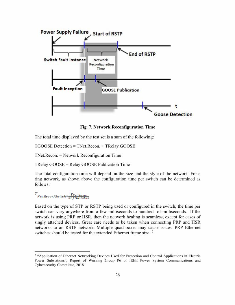
Fig. 7. Network Reconfiguration Time
The total time displayed by the test set is a sum of the following:
TGOOSE Detection = TNet.Recon. + TRelay GOOSE
TNet.Recon. = Network Reconfiguration Time
TRelay GOOSE = Relay GOOSE Publication Time
The total configuration time will depend on the size and the style of the network. For a ring network, as shown above the configuration time per switch can be determined as follows:
Based on the type of STP or RSTP being used or configured in the switch, the time per switch can vary anywhere from a few milliseconds to hundreds of milliseconds. If the network is using PRP or HSR, then the network healing is seamless, except for cases of singly attached devices. Great care needs to be taken when connecting PRP and HSR networks to an RSTP network. Multiple quad boxes may cause issues. PRP Ethernet switches should be tested for the extended Ethernet frame size. 7
7 “Application of Ethernet Networking Devices Used for Protection and Control Applications in Electric Power Substations”, Report of Working Group P6 of IEEE Power System Communications and Cybersecurity Committee, 2018

27
4.5 How to test sampled values (SV)
The principle of testing a merging unit of IEC 61850 9-2 that produces a sampled value stream (SV) is similar to traditional meter testing where a reference meter is used to compare and establish the accuracy of the output values of the meter under test. However, the SV stream involves some special consideration due to the time stamp and multicast message components.
In order to directly compare two SV streams the time reference becomes critical especially if the object of the test is calibration as in Fig. 8. This is a result of the device or application receiving the SV stream needing to time align the samples based on the time stamp of the messages. It also has to determine if any samples are missing or if any packets have been lost to know the stream values as reconstructed are valid for use. The concept of quality status dictates that both the reference SV stream and the SV stream under test be time aligned for the analysis.
Fig. 8. Closed loop test of Merging Unit
28
Anytime communication-based analysis of packet data is performed, there is a need to handle the "jitter" of the received packets. This is due to the network latencies inherent in any such system. There arises a need for the analysis procedure to average these values within an acceptable "jitter" tolerance in addition to the other tolerances of the devices used and tested.
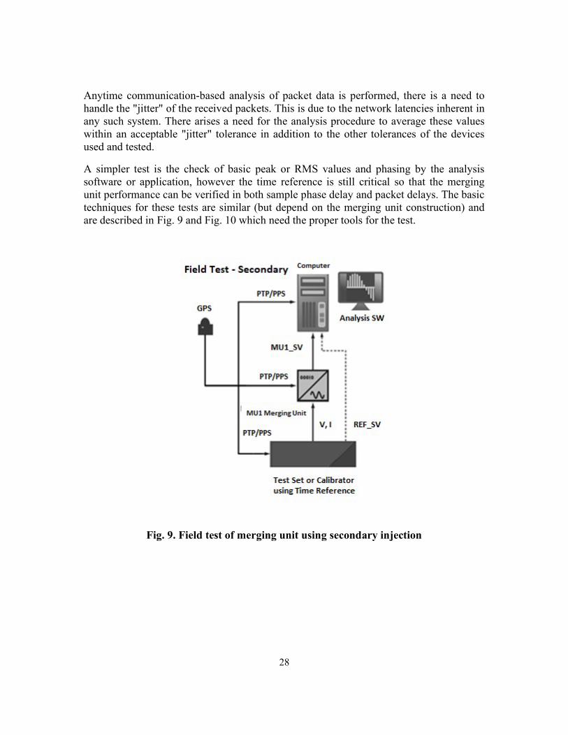
A simpler test is the check of basic peak or RMS values and phasing by the analysis software or application, however the time reference is still critical so that the merging unit performance can be verified in both sample phase delay and packet delays. The basic techniques for these tests are similar (but depend on the merging unit construction) and are described in Fig. 9 and Fig. 10 which need the proper tools for the test.
Fig. 9. Field test of merging unit using secondary injection

29
Fig. 10. Field test of merging unit using primary injection
4.5.1 Time Reference
When comparing sampled value streams a time reference is crucial. The accuracy of the time signal (mean error from absolute time) is expected to be better than +/- 1μs or +/-4μs for accuracy characterization depending on the class of precision (T4\T5). Two widely used methods that provide the necessary accuracy are Precision Time Protocol (PTP) per IEEE 1588, IEC 61588:2009 and IEC/IEEE 61850-9-3; and One Pulse per Second (1PPS). Consider using PTP for systems implementing IEC 61850-9-2:2011/AMD1:2019. Testing of the time synchronization in a substation network will help to assure the accuracy and the reliability of the information. Time synchronization testing is critical when process bus signals are exchanged between multiple IEDs for purposes of protection calculations that result in autonomous control actions on the power
30
system. The time synchronization testing is comprised of testing devices such as merging units and other IEDs as well as the overall network time synchronization performance8.
When testing the network, a time synchronization testing device can be utilized to analyze the difference of time between the grand master clock and each IED, including the merging units, to validate that the time error tolerance is within an acceptable margin. The tests aid the user in confirming at least the following:
a) That the merging unit is providing the correct information about its time condition in the SmpSynch attribute. Per the IEC 61850-9-2:2011 standard, the SmpSynch attribute is an 8 bit integer that identifies whether or not the time of the merging unit is synchronized by an external clock signal and includes some information that is used to identify the source of time synchronization. For instance: SmpSynch = 0 means that the device is not synchronized by any external time source. SmpSynch = 1 means that the device is synchronized by a local time source that is not globally identified (or UTC time traceable). SmpSynch = 2 means that time is synchronized by a traceable global time signal. SmpSynch = 5 through 254 means that the time is synchronized by a local source and that source is identified by the number 5 through 254. The values of 3, 4 and 255 are not allowed for SmpSynch. Another check that one might want to do is to check that the SmpSynch field changes to “local” or “internal” when the time synch signal is not available. One method that can be used to simulate these conditions is by disconnecting the GPS antenna. Since there could be several redundant master clocks in the network, and sometimes the IEDs themselves can become a master clock for other IEDs, it is preferable to test the device with a single Master Clock configuration. 9
b) That the merging unit is properly updating value timestamps and providing
appropriate alarms to indicate time synchronization error/failure.
8 Please refer to the network engineering guidelines, IEC TR 61850-90-4.
9 An updated version of the IEC 61850-9-2 referred to as Ed2.1 and expected to be named IEC 61850-9-2: AMD1:2019 (Amendment 1) is being updated to restrict the usage of the SmpSynch field to the values of 0, 1, or 2 only. Instead of using the values of 5 through 254 to identify the time source master, an additional optional field named “SynchSrcID” is being added to the IEC 61850-9-2 PDU to hold the “grandmasterIdentity” field specified by clause 13.5 of IEEE 1588 (IEC 61588:2009). The IEC technical committee is strongly suggesting that the SynchSrcID be used to identify the time synch master when PTP is used because it more clearly identifies the time synchronization master for improved time traceability.

31
c) The accuracy of the time synchronization of the merging units and IEDs is within
+/- 1μs or +/-4μs depending on the class of precision (T4\T5) needed for the system.
4.6 IEC 61850 Edition 2 Features Related to Testing
IEC 61850-based protection automation and control systems can have functions that consist of multiple functional elements or logical nodes that may interact with each other. The various functions may be part of different logical devices or even located in different physical devices. Communication messages between publishers and subscribers are constantly monitored to detect anomalies in the communication path and defects in IEDs. Therefore, the traditional way of testing a device by disconnecting it from the rest of the system may result in multiple alarms and failures of some functions that depend on other functions.
IEC 61850 provides features for the purpose of properly isolating a function or a clearly defined cluster of interdependent functions without disturbing the other parts that are in normal operation. Edition 1 of the standard provided some features for this purpose but was ambiguous and not mandatory in many cases. Vendors did not implement them or implemented them according to their understanding of the standard. Utilities and solution providers that started to use IEC 61850 had to employ additional customization to provide logic to accomplish isolation of functions or entire IEDs for the purpose of testing. These custom solutions had some success but there was no standardization and it was not possible to test a function without taking the entire IED out of service. Edition 2, Parts 7-1 through 7-4 and 8-1 of the standard have greatly clarified these features,10, 11, 12,
13, 14 added new features, and made mandatory many of these features. The key features related to testing are described here. While most of these testing features apply to GOOSE message as well as sampled values and most control commands using client communications, this discussion will focus on the use of GOOSE messages.
10 IEC 61850-7-1:2011, Communication networks and systems for power utility automation – Part 7-1: Basic communication structure – Part 7-1: Principles and models 11 IEC 61850-7-2:2010, Communication networks and systems for power utility automation – Part 7-2: Basic communication structure – Abstract communication service interface (ACSI) 12 IEC 61850-7-3:2010, Communication networks and systems for power utility automation – Part 7-3: Basic communication structure – Common data classes 13 IEC 61850-7-4:2010, Communication networks and systems for power utility automation – Part 7-4: Basic communication structure – Compatible logical node classes and data object Classes 14 IEC 61850-8-1:2011, Communication networks and systems for power utility automation – Part 8-1: Specific communication service mapping (SCSM) – Mappings to MMS (ISO 9506-1 and ISO 9506-2) and to ISO/IEC 8802-3

32
4.6.1 Simulation
Every GOOSE message header has a Simulation parameter or flag (formerly called Test in edition 1) that can be set to TRUE or FALSE and is used only for test device that simulates GOOSE messages. Real IEDs inherently always publish GOOSE messages with the Simulation flag set to FALSE.
For subscription, the physical device logical node LPHD data Sim.stVal at the IED level can be set to TRUE or FALSE. This allows the IED to select the GOOSE messages that have yet to be processed. During normal operation the Sim.stVal is set to FALSE and it receives and processes GOOSE messages from other real IEDs. Depending on the purpose of the test, the test set can be set to publish messages with the simulation flag set to FALSE or TRUE, especially in a laboratory environment to test either in-service conditions or maintenance test scenarios. In order to test an IED during maintenance, one sets its Sim.stVal data to TRUE; and the test device then publishes GOOSE messages with the simulation flag set to TRUE.
Fig. 11 shows three IEDs with an IEC 61850 test set to test IED1. Before testing, under normal operating conditions where the IED1 LPHD1.Sim.stVal = FALSE, IED1 receives GOOSE messages GOOSE1 and GOOSE2 from IED2 and GOOSE3 from IED3, and all GOOSE messages published by IED2 and IED3 having the simulation flags of FALSE. All three GOOSE messages are processed by the application function WXYZ1.
Setting IED1 LPHD1.Sim.stVal to TRUE, but without yet injecting the test GOOSE1 message from the test set, IED1 would continue to process the GOOSE1 message from the real IED2 even though its Simulation flag is FALSE. When the test set injects a similar GOOSE1 message with its Simulation flag set to TRUE IED1 (also with Sim.stVal=TRUE) then starts to process GOOSE1 from the test set and stops processing GOOSE1 (simulation flag=FALSE) from IED2. However, it continues to process GOOSE2 and GOOSE3 messages since there are no similar test GOOSE messages in the network; if there is to be a simulated or test GOOSE3 message, IED1 then stops processing the real GOOSE 3 from IED3 and starts processing the test GOOSE3 message with a simulation flag of TRUE. IED1 still continues to process GOOSE2 from the real IED2 since there is no test GOOSE2 message in the network. If the test set now stops injecting the test GOOSE1, IED1 continues to not process the GOOSE1 message from the real IED2 even though there is only one GOOSE1 message, until the IED1 LPHD1.Sim.stVal is reset to FALSE.

33
Fig. 11. Simulation feature for selection of GOOSE message for processing
As a result, one can see that the IEC 61850 “isolation” using the simulation feature is not completely equivalent to the use of a conventional test switch where the normal input signals to an IED are disconnected and test signals injected. In IEC 61850 the test GOOSE messages and the real GOOSE messages can be simultaneously in the network but are logically diverted within the IEDs that contain the functions being tested based on the simulation flag and the setting of Sim.stVal of the IEDs. Injecting a similar test message with simulation flag of FALSE at the same time as a real message from a real IED with their simulation flags set to FALSE could prove to be problematic as there could be potentially conflicting messages.
In addition to IED LPHD Simulation where the GOOSE messages to be processed are selected, further processing of the data contained in the selected GOOSE messages depend on the quality attribute (defined in IEC 61850-7-3) of the individual data signals in the GOOSE message, and the mode/behavior of the application functions (WXYZ1 and MNOP1 in the figure) that consume them.15
15 IEC 61850-7-3:2010, Communication networks and systems for power utility automation – Part 7-3: Basic communication structure – Common data classes
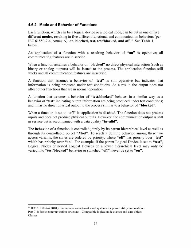
34
4.6.2 Mode and Behavior of Functions
Each function, which can be a logical device or a logical node, can be put in one of five different modes, resulting in five different functional and communication behaviors (per IEC 61850-7-4, Annex A): on, blocked, test, test/blocked, and off.16 See Table 1 below.
An application of a function with a resulting behavior of “on” is operative; all communicating features are in service.
When a function assumes a behavior of “blocked” no direct physical interaction (such as binary or analog outputs) will be issued to the process. The application function still works and all communication features are in service.
A function that assumes a behavior of “test” is still operative but indicates that information is being produced under test conditions. As a result, the output does not affect other functions that are in normal operation.
A function that assumes a behavior of “test/blocked” behaves in a similar way as a behavior of “test” indicating output information are being produced under test conditions; and it has no direct physical output to the process similar to a behavior of “blocked”.
When a function is set to “off” its application is disabled. The function does not process inputs and does not produce physical outputs. However, the communication output is still in service but is accompanied with a data quality “invalid”.
The behavior of a function is controlled jointly by its parent hierarchical level as well as through its controllable object “Mod”. To reach a definite behavior among these two access variants, the states are ordered by priority, where “off” has priority over “test” which has priority over “on”. For example, if the parent Logical Device is set to “test”, Logical Nodes or nested Logical Devices on a lower hierarchical level may only be varied into “test/blocked” behavior or switched “off”, never be set to “on”.
16 IEC 61850-7-4:2010, Communication networks and systems for power utility automation – Part 7-4: Basic communication structure – Compatible logical node classes and data object Classes

35
Table 1. Behavior of Logical Nodes resulting from Modes of Hierarchical Logical Devices and Logical Nodes.
LNMode or nested LDMode XXXX.Mod
LDMode LLN0.Mod
LNBeh (read only) XXXX.Beh
on on on on on
On blocked test test/blocked off
on blocked test test/blocked off
blocked blocked blocked blocked blocked
On blocked test test/blocked off
blocked blocked test/blocked test/blocked off
test test test test test
On blocked test test/blocked off
test test/blocked test test/blocked off
test/blocked test/blocked test/blocked test/blocked test/blocked
On blocked test test/blocked off
test/blocked test/blocked test/blocked test/blocked off
off off off off off
On blocked test test/blocked off
off off off off off
To isolate a function from the rest of the normal system for testing, its data Mod.stVal can be set to “test” to change its behavior Beh.stVal to “test”. If it has a physical output, “test/blocked” is selected to prevent it from issuing that output. A function under test with behavior of test or test/blocked correspondingly sets its output signal's quality attribute “q.test” bit to TRUE.

36
Fig. 12. Modes and Behavior of Logical Nodes and processing of incoming data
Fig. 12 provides an insight into the processing of information specific for the states of a function. “Processed as valid” means that the application reacts in a manner that is foreseen for “test”. “Processed as invalid” means that the application reacts as if the quality of the data had been invalid.
4.6.3 Transmission of outputs and processing of Inputs
Information is transmitted between a publishing function and a subscribing function, and it is not only the status value or measurement value of a data object. The publishing function conveys additional information, such as data quality. This quality information related to the value is necessary for the correct understanding and processing of the value by the subscribing function. The output and quality bits related to the data value during testing are shown in Table 2.
Different data attributes can be used as the inputs for the subscribing functions which define how to handle the value in an application specific way. If the test bit in the quality attribute of a data object is different from the behavior (Beh) of the subscribing function, the application deals with the input in a way which reflects the definitions in Table 2 and Table 3. In these tables, the function behind the logical node is OFF when the mode/behavior is off. In all other cases of mode/behavior the function is always ON. These two tables are based on IEC 61850-7-4 Tables A1 and A2.17
17 IEC 61850-7-4:2010, Communication networks and systems for power utility automation – Part 7-4: Basic communication structure – Compatible logical node classes and data object Classes

37
Table 2. Effect of Publisher mode/behavior on output and published quality information
Mode/Behavior on blocked test test/blocked off Quality information related to data signals
q is relevant
no q=test q=test/operatorBlocked q=invalid
Physical output to the process
yes no yes no no
Table 3. Effect of Subscriber mode/behavior on processing of incoming data
Mode/Behavior on blocked test test/blocked off Incoming data with q=normal
Processed as valid
Processed as valid
Processed as valid
Processed as valid Not Processed
Incoming data with q=test Processed as valid
Processed as invalid
Processed as valid
Processed as valid Not Processed
Incoming data with q=invalid
Processed as invalid
Processed as invalid
Processed as invalid
Processed as invalid Not Processed
Non-IEC 61850 (physical) inputs
Processed Processed Processed Processed Not Processed
For a function which is “on” or “blocked”, the user expects that its processing is not affected by information published by another function under test. Signals marked as “test” are not considered for processing by functions operating normally. Therefore, the application of a function in an “on” or “blocked” state tends to ignore input signals with q.test set to TRUE.
On the contrary, a function which is set to “test” or to “test/blocked” processes “as valid” messages with q.test = TRUE as well as messages with q.test = FALSE, assuming q.validity = good. This characteristic provides interoperability of functions in the way that the applications are expected to work and is typically considered in the test methodology.
The “invalid” indication of the signal means that the value is not to be used. In the subscribing function, the communication services take note that information was received, but the application does not consider the value for its processing. Processing of signals with an indication of “questionable” depends on the application that uses the value. The behavior of the subscribing functions upon reception of invalid or questionable data is included in the test scope. The publishing function when ranking why a value is marked “invalid” or “questionable” depends also on the application and uses additional detailed quality identifiers such as "Overflow", "Out of Range", "Bad
38
Reference", "Oscillatory", "Failure", "Old data", "Inconsistent", and "Inaccurate". The subscribing function can also evaluate the detailed quality identifiers to derive the most appropriate way of processing of the information.
5. HOW TO CONNECT TO A NETWORK TO TEST IEC 61850 DEVICES
The process of actually connecting to an IEC 61850 network is not difficult as it only requires plugging an Ethernet cable into a switch of the network. However, what that connection allows is the key issue and is determined by the network topology, how it is engineered for traffic flow, and the security in place. So, the actual question presented is "How is the network designed for testing?"
There are many operational and safety procedures that are in place for traditional protection, automation, and control (PAC) testing in a typical substation. Some are common among utilities while others are unique to a single utility. Converting these procedures into equivalent network based or virtual procedure steps is an essential consideration for implementing the IEC 61850 technologies.
5.1 Using VLANs as an Isolation Tool for IEC 61850 Applications
VLANs are logically separate Ethernet networks. Even though devices may share physical cabling or equipment, Ethernet packets cannot be shared between devices in different VLANs without a Layer 3 device, like a router for example. VLANs can serve as a powerful isolation tool when networking a group of devices because most network switches have the ability to be partitioned into multiple VLANs and each port on the switch can be configured to access specific VLANs defined by the user. The user will need to use the switch vendor's configuration tools to add, remove, or modify which ports on a switch will pass traffic from a specific VLAN (or set of VLANs) or moved the traffic from one VLAN to another. Disable switch ports that are not used to prevent an unauthorized device from being able to connect to the network.
To use a VLAN, a trunk is required to make sure all traffic is exchanged between switches or to allow network monitoring tools to view all the traffic. A trunk port is a port that is assigned to carry traffic for all the VLANs that are accessible by a specific switch, a process known as trunking. Trunk ports mark frames with unique identifying tags; either 802.1Q tags or Inter-Switch Link (ISL) tags, as they move between switches. Ethernet trunks carry the traffic of multiple VLANs over a single link and can be extended to the VLANs across an entire network (such as for IEC 61850 applications). Interfaces (access ports) are defaulted to be in a non-trunking mode, meaning those access ports will carry only those VLANs for which it is configured. Thus, the user needs to configure trunk ports in permanent trunking mode using the switch’s configuration tools.

39
Using the test VLANs does provide the following benefits:
• Configuring each switch port allows individual GOOSE messages on multiple devices through multiple switches to be isolated and tested by maintaining the same VLAN ID without having to reconfigure the IEDs.
• Network Isolation via VLANs provides overlapping testing
Due to the drawbacks of reconfiguring switches versus reconfiguring IEDs and test bits by custom logic, IEC 61850 edition 2 test features enable one to verify path of real time configuration of a switch.
There are other network tools such as MAC filtering that can be used for network isolation. Static or dynamic MAC filtering or similar approaches may be used.
5.2 Identify the various scenarios of IED configurations that need to be tested and how
Communications, network architectures and relays capabilities have evolved during recent years to make the grid smarter, faster and reliable. However, when deploying projects based on IEC 61850, to-date there are no specific requirements related to network architecture or project design. There are some important factors affecting Network or protection scheme based on GOOSE. It is important to perform some tests to measure the performance of the IEC 61850 solution.
5.2.1 Network Architecture Test
The first criterion of testing IEC 61850 implementation is the response/recovery time.
Table 4 below presents typical recovery times for various protocols and architectures.
Table 4. Redundancy protocols specified in IEC 62439
Protocol Solution Frame Loss
Redundancy Protocol
End node Attachment
Network Topography
Recovery time for the considered failures
IP IP routing Yes Within the network
Single Single meshed > 30 s typical
not deterministic
STP IEEE 802.1D
Yes Within the network
Single Single meshed > 20 s typical
not deterministic
RSTP IEEE 802.1D
Yes Within the network
Single Single meshed, ring
Can be deterministic following the rules of Clause 8

40
Protocol Solution Frame Loss
Redundancy Protocol
End node Attachment
Network Topography
Recovery time for the considered failures
CRP IEC 62439-4
Yes In the end nodes
Single and double
Doubly meshed, cross-connected
1 s worst case
for 512 end nodes
DRP IEC 62439-6
Yes Within the network
Single and double
Ring, double ring
100 ms worst case
for 50 switches
MRP IEC 62439-2
Yes Within the network
Single Ring 500 ms, 200 ms, 30 ms, or 10 ms worst case
for 50 switches depending on the parameter set
BRP IEC 62439-5
Yes In the end nodes
Double Doubly meshed, connected
4.8 ms worst case
for 500 end nodes
PRP IEC 62439-3
No In the end nodes
Double Doubly meshed, independent
0 s
HSR IEC 62439-3
No In the end nodes
Double Ring, meshed 0 s
The newest types of architectures such as HSR and PRP have (0ms) recovering times. Testing the response/recovery time of these new protocols is easier than that of legacy protocols such as RSTP. Many modern tests, through the use of widely available TCP/IP diagnostic tools, isolate/break one ring to allow the observation of the recovery time for the entire system. A significant number of other architectures depend upon the Ethernet switch configuration, for which calculations become necessary to confirm that system performance is within acceptable limits.
For example, when using RSTP, the maximum recovery time of the architecture depends upon the switch configuration and number of switches used.
Total re-configuration time=TL + (N - 3)*TPA, if N is even Total re-configuration time=TL + (N - 2)*TPA, if N is odd Where:
N - number of switches in the ring TL - time required by a switch to detect a link failure TPA - time required by a pair of switches to perform RSTP.
5.2.2 Protection Scheme anomalies

41
The second criterion to consider when testing IEC 61850 system is the protection scheme. Protection applications like a busbar scheme, automatic transfer scheme or breaker failure may be accomplished using GOOSE messages instead of traditional hardwire methods. This allows for reduced cost and complexity of the installation. The concept of testing schemes is not the topic of this literature, because testing depends upon the methods used and the scheme scenarios, however when using a protection scheme based on GOOSE messages it is very important to consider the performance of GOOSE subscribing and publishing.
The test below (see Fig. 13) describes how the performance of subscribing and publishing can be done between relays from the same family or multiple vendors. The time of subscribing and publishing in two different directions can then be calculated.
Fig. 13. Performance of GOOSE subscribing and publishing test
After testing the protection scheme as described, the tester can retrieve time-stamped events from a Sequence of Events log to confirm the performance of the GOOSE messages.
The performance of the GOOSE messaging is a critical aspect of the IEC 61850 communication as it is used to exchange process data in real time between the IEDs on the network.
The second consideration when testing the performance of publishing and subscribing is to consider the worst-case scenario, it is possible that the traffic of GOOSE can affect the communication operating time.
It simplifies testing to begin with one subscriber, and then define a worst-case scenario, for a maximum number of subscribers that can be tested. In some cases, there is a limitation on the number of GOOSE messages to which an IED can subscribe; however, this hopefully has been addressed during engineering of the system.

42
Fig. 14. GOOSE Performance test
To measure the impact of the size of the GOOSE frame and the number of subscribed GOOSE messages a number of test cases are performed. See Fig. 14 above. The relay will send 1 GOOSE output message which is subscribed by the test device, the time recorded is for all virtual outputs mapped in the published GOOSE frame to be updated. The test device will publish from 1 to 32 GOOSE messages each with 1 status point. For the relay to respond, all expected GOOSE messages need to have been received and processed.
In case there are multiple vendors to test, each type of relay is generally tested separately.
5.2.3 Publishing and subscribing IEDs reporting capabilities
The third and most interesting criterion is the GOOSE fail alarm from the relay. When the publisher fails to publish GOOSE, each subscriber recognizes the situation and takes appropriate action or lack thereof depending on the design criteria, (force, block or keep the condition as last known condition) When employing a protection scheme based on GOOSE, losing network may lead to a failure to trip or other tripping issues unless there is a back-up solution for this situation. Verification of relay behavior in this type of situation is necessary to avoid unexpected behavior. Digital data looking to different layers in the OSI model can provide operators this type of information.

43
6. SECURITY CONSIDERATIONS FOR IEC 61850 GOOSE TESTING AFTER COMMISSIONING
Consider within the broader scope of security in computer operations performing IEC 61850 GOOSE testing after the equipment is initially commissioned.18,19,20
Access Control/ Personnel issues
Restrict access to IEC 61850 equipment to personnel that need access and replace default passwords with user defined passwords.
Additional access granted for testing can introduce security vulnerabilities. Properly screen employees and contractors performing GOOSE testing. Full background checks may be used in a vetting process.
Supervision of external personnel/ those without standard access
Verify diagnostic ports are used by authorized personnel (Authentication, etc) Disable external access added for maintenance once maintenance is completed
System Maintenance Tools
System maintenance tools are approved and monitored (DHS- CCSS 2.10.7)21 • Inspect or test new software, upgrades, or custom software before it is
loaded • Inspect computers/ test equipment that will be connected • DHS- CCSS 2.10.7 covers more22
Physical Access Protection: Lock away GOOSE testing tools, software media, computers that access substation equipment to prevent tampering when the equipment is not in use. However, this is probably not a practical solution. What may be required is role-based access where any person logging onto the network is identified through the login process. (Note: when logging into a relay, through a RADIUS server, the protocol captures the identification of the person logging in.)
18 An Introduction to Computer Security: The NIST Handbook 19 Catalog of Control Systems Security: Recommendations for Standards Developers, April 2011, https://www.hsdl.org/?abstract&did=8002 20 NISTIR 7628 – Guidelines for Smart Grid Cyber Security http://www.us-cert.gov/control_systems/csstandards.html 21 Catalog of Control Systems Security: Recommendations for Standards Developers, April 2011, https://www.hsdl.org/?abstract&did=8002 22 Catalog of Control Systems Security: Recommendations for Standards Developers, April 2011, https://www.hsdl.org/?abstract&did=8002

44
General Considerations
Poor documentation, conflicting software, and poor control of maintenance accounts undermine security
Disposal: Treat any test data as sensitive, properly sanitize media that contains test data.
Documentation: Add GOOSE testing security procedures to the substation security procedures documentation
Unplanned Maintenance (DHS- CCSS 2.10.5.1): Log any maintenance with who accessed system and what equipment was used 23
Planned maintenance (DHS- CCSS 2.10.6.1): approval, log details, sanitize equipment, verify security following maintenance24
Perform final tests with all security measures enabled (e.g. firewalls). Security equipment such as firewalls can add significant latency in addition to completely blocking communications if not configured properly.
Documentation: Securely archive a copy of the final as-left SCD file in order to be able to rebuild the system in the event of component failure or testing modification.
Documentation: Securely archive a copy of the final as-left configuration(s) for all Switches and any other network devices.
Supply Chain Issues (NISTIR 7628 SG.SA-11)25
• Due diligence review of suppliers
• Diverse set of suppliers
• Independent analysis and penetration testing
23 Catalog of Control Systems Security: Recommendations for Standards Developers, April 2011, https://www.hsdl.org/?abstract&did=8002 24 Catalog of Control Systems Security: Recommendations for Standards Developers, April 2011, https://www.hsdl.org/?abstract&did=8002 25 NISTIR 7628–Guidelines for Smart Grid Cyber Security. [Online] Available: http://www.us-cert.gov/control_systems/csstandards.html

45
7. SYSTEM PERFORMANCE VALIDATION
IEC 61850 defines a system as “The logical system is a union of all communicating application-functions performing some overall task like 'management of a substation', via logical nodes. The physical system is composed of all devices hosting these functions and the interconnecting physical communication network. The boundary of a system is given by its logical or physical interfaces. Within the scope of the IEC 61850 series, ‘system’ always refers to the Substation Automation System (SAS), unless otherwise noted”.26
System testing can be performed in a top-down or bottom-up approach. This is to a great extent dependent on the purpose of the test. If the test is a factory acceptance test it might be a good idea to use the bottom-up approach. In this case the testing starts first with the individual parts of the system – the functional elements. They are then grouped together to form subfunctions or functions, which are in turn linked into more complex functions until the complete system is tested.
System testing looks at the overall performance of the system from an external observer's point of view.
In the top-down testing model the system is defined as a whole with its boundaries and behavior, without considering the details for any part of it (Black Box Test Method). Each sub-component of the system then can be tested using the same approach until the bottom of the functional hierarchy is reached and functional elements testing may be performed.
In considering the performance of the tested functional elements through the functional hierarchy to sub-functions until the overall system tests are concluded, the oft-preferred approach is to use the White Box Test Method (e.g., Fig. 15) where the anticipated interactions of the functions and subsystems are known and can be used to evaluate the overall system performance.
In all cases it is important to clearly identify the system or function boundary that defines the parameters/boundaries for simulation by the test system and monitoring the behavior of the tested function.
26 An Introduction to Computer Security: The NIST Handbook

46
Fig. 15. Function boundary definition of known system
In Fig. 15 above, SF indicates a subfunction that contains K functional elements. The functional elements are the smallest component in the system that can be defined with a function boundary, interface and behavior (i.e., that can be tested). It becomes clear in Fig. 16 that the parameters for testing change significantly depending on where the system boundary is drawn.
Fig. 16. Full system architecture
7.1 How to test redundancy?
The testing of distributed bay and substation level functions that are based on communications only – IEC 61850 8 – 1 or 9 – 2 are similar functionally to the testing an individual IEDs. The main difference is that in this case there are multiple test devices with virtual simulators or analog outputs. The simulation of the substation and system environment needed for the functional testing of bay and system level functions result in the simulation of multiple merging units (IEC 61850 9-2 interface) and other IEDs (IEC 61850 8-1 interface).

47
IEDs that are used in a hybrid application would be tested individually before the overall system test could be verified. The example that follows would be one such possibility.
Fig. 17. Testing of IED with SMV and hard wired interface
Fig. 17 shows the system configuration for hybrid testing of IEDs that have relay outputs and at the same time support GOOSE messages.
The evaluation of the performance of the distributed functions in this case is based on the subscription of the test system components to the GOOSE messages from the different IEDs participating in the tested distributed applications. If these devices also have relay outputs hard-wired to the test devices, monitoring their operation may also be necessary in order to evaluate the performance of the tested system and if necessary compare the communications based to hard-wired solutions.27 A simplified block diagram of this test system is shown in Fig. 18.
27 Catalog of Control Systems Security: Recommendations for Standards Developers, April 2011, https://www.hsdl.org/?abstract&did=8002
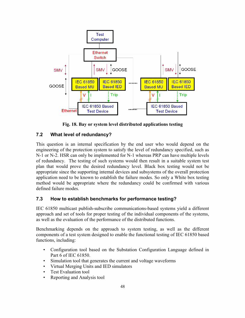
48
Fig. 18. Bay or system level distributed applications testing
7.2 What level of redundancy?
This question is an internal specification by the end user who would depend on the engineering of the protection system to satisfy the level of redundancy specified, such as N-1 or N-2. HSR can only be implemented for N-1 whereas PRP can have multiple levels of redundancy. The testing of such systems would then result in a suitable system test plan that would prove the desired redundancy level. Black box testing would not be appropriate since the supporting internal devices and subsystems of the overall protection application need to be known to establish the failure modes. So only a White box testing method would be appropriate where the redundancy could be confirmed with various defined failure modes.
7.3 How to establish benchmarks for performance testing?
IEC 61850 multicast publish-subscribe communications-based systems yield a different approach and set of tools for proper testing of the individual components of the systems, as well as the evaluation of the performance of the distributed functions.
Benchmarking depends on the approach to system testing, as well as the different components of a test system designed to enable the functional testing of IEC 61850 based functions, including:
• Configuration tool based on the Substation Configuration Language defined in Part 6 of IEC 61850.
• Simulation tool that generates the current and voltage waveforms • Virtual Merging Units and IED simulators • Test Evaluation tool • Reporting and Analysis tool

49
If the tested device has relay outputs as well, it becomes possible to compare their operation with the received GOOSE messages to determine if the performance of communications-based solutions is analogous to the hard-wired case.
The test system may also retrieve the waveform records from the tested device and again compare them with the original waveforms from the simulation tool.
In all cases the ability to benchmark the performance of the defined system is critical to the successful implementation of the desired protection and control application.
8. SAMPLE CASES
8.1 Sample Test Case:
Overview:
BPA engineers performed single vendor Fixed GOOSE messaging over Ethernet LAN testing to verify that the availability of GOOSE messages with a delay meeting P2/P3 requirements per the standard. There were a total of 5 tests performed on a LAN consisting of 4 IEDs sending GOOSE messages at a rate of ~400 GOOSE messages/second to a single aggregator IED that measured and counted the one way delay of each GOOSE message state change from off to on. The 5 tests performed were:
• 4 IEDs sending GOOSE messages to the aggregator IED synchronously or at the same time.
• 4 IED’s sending GOOSE messages to the aggregator UR asynchronously or with 8ms delays between each message.
• Quality of service (QoS) on the switch disabled versus enabled. QoS is an advanced feature that prioritizes internet traffic for Ethernet ports or specified MAC addresses to minimize the impact of busy bandwidth.
• Monitor GOOSE messages received asynchronously while downloading event files from aggregate IED via Ethernet LAN vs. IED serial port
• Internal Broadcast Denial of Service Attack (DoS) with the switch Broadcast Protect enabled versus disabled.
No unicast or multicast DoS testing was performed due to the lack of any unicast or multicast protection features available on the switch.
9. CONCLUSION
This report provides insight into how to test networks that utilize IEC 61850 for protection and control with an emphasis on GOOSE messaging. Traditional testing versus modern testing methods, the need for good documentation, testing of GOOSE and sampled values, test connections, and performance verification are just some of the topics that are discussed.