ha7.lehurst designs limited
TRANSCRIPT

FEBRUARY 195
Insu at on testing.
Ionisation testing.
Electron-optical equip-
ment. Geiger-Muller
Tubes. Photo multiplier
Tubes. High speed cath-
ode ray tubes. Chemic. I , lysis.
Electrostatic precipitation. Air
Cleaning, etc.
Full lists and prices sent o. uest
HA7.LEHURST DESIGNS LIMITED 34a,POTTERY LANE, LONDON, W.II. Telephone PARK 6955/5237
TWO SHILLINGS
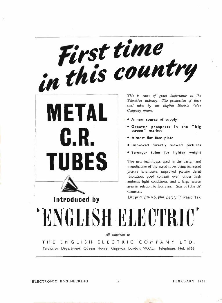
first time itt this country
METAL C.R.
TUBES introduced by
This is news of great importance to the
Television Industry. The production of these
steel tubes by the English Electric Valve
Company means:
• A new source of supply
• Greater prospects in the " big screen " market
• Almost flat face plate
• Improved directly viewed pictures
• Stronger tubes for lighter weight
The new techniques used in the design and
manufacture of the metal tubes bring increased
picture brightness, improved picture detail
resolution, good contrast even under high
ambient light conditions, and a large screen
area in relation to face area. Size of tube 16"
diameter.
List price £16.o.o, plus £4.3.3. Purchase Tax.
'ENGLISH ELECTRIC' All enquiries to
THE ENGLISH ELECTRIC COMPANY LTD.
Television Department, Queens House, Kingsway, London, VV.C.2. Telephone: Hol. 6966
ELECTRONIC ENGINEERLNG ii FEBRUARY 1951
CLASSIFIED ANNOUNCEMENTS
The charge for these advertisements at the LINE RATE (if under I or 12 lines) is : Three lines or under 7/6, each additional line 2/6. (The line averages s words.) Box number 2/- extra, except in the case of advertisements in" Situations Wanted," when it is added free of charge. At the INCH RATE (if over l' or 12 lines) the charge is 30/. per inch, single column. Prospectuses and Company's Financial Reports £14 Os. Od. per column. A remittance must accompany the advertisement. Replies to box numbers should be add d to : Morgan Bros. (Publishers), Ltd., 28, Essex Street, Strand, London, W.C.2, and marked " Electronic Engineering." Advertisements
must be received before the 14th of the month for insertion in the following issue.
OFFICIAL APPOINTMENTS
B.B.C. invites applications for a post of Engineer in the Studio Section (Recording) of Planning and Installation Department, based in London. Applicants should have a good theoretical and practical knowledge of the principles involved in audio-frequency and sound-recording work. A University Degree in Electrical Engineering, or equivalent qualifications, would be an advantage. The successful candidate must be prepared to spend a considerable amount of time away from London, as he will be required to plan and supervise the installation of sound-recording equipment at any of the Corporation centres throughout the country. Starting salary, £745 per annum (may be higher if qualifications and experience are exceptional). rising by annual increments on a five-year pro-gression to £965 per annum. The successful applicant will become eligible for consideration for appointment to established staff (Contributory Pension Scheme) after two years' qualifying period. Applications, stating age, qualifications and experience, to reach Engineering Establishment Officer, Broadcasting House, London, W.I, within seven days. W 2661
ADMIRALTY. Vacancies exist for Electrical and/or Mechanical Engineering Draughtsmen in Admiralty Research and Development Establish-ments located in the vicinity of Weymouth, Ports-mouth, Teddington (Middlesex) and Baldock (Herts.). Draughtsmen experienced in light current, electro-mechanical, precision mechanical and electronic equipment are particularly needed. Candidates must be British subjects of 21 years of age and upwards, who have had practical workshop experience (preferably an apprenticeship), together with drawing office experience. Appointments will be in an unestablished capacity, but oppor-tunities may occur for qualified staff to compete for established posts. The salaries offered, depending on age, experience, ability and place of duty, will be within the range £283-£510 per annum. Exceptionally well-qualified candidates may be considered for appointment in a higher grade within the salary range £470-£610 per annum. Hostel accommodation is available at some establishments. Applications, stating age and details of technical qualifications and apprentice-ship (or equivalents) and workshop and drawing office experience, should be sent to Admiralty (C.E.II, Room 88), Empire Hotel, Bath. Original testimonials should not be forwarded with applica-tion. Candidates required for interview (at London or Bath, whichever is nearer) will be advised within two weeks of receipt of application. W 2687
SITUATIONS VACANT
DEVELOPMENT ENGINEERS required by firm in N.W. London manufacturing an extensive range of industrial instruments and controls. Candidates should have a good theoretical background, preferably with a Degree, or equivalent, in Physics or Electrical Engineering, and in addition should have experience in one of the following: (a) Industrial instruments and process control. (b) Servo mechanisms. (r) Magnetic amplifier design. (d) Application of electronics to industrial measurements and control. The starting salary will be according to the experience of the applicant, ranging from £400 per annum for Junior Engineers, to £650 per annum for specially qualified applicants. Write Box No. W 2696.
PROTOTYPE WIREMEN required for producing highest grade television transmission and other equipment. Applicants should possess sound fundamental knowledge of both radio and television, together with some experience of layout and wiring of video equipment. Wiring to be of instrument standard and applicants must be capable of producing own component layouts. City and Guilds, High Nat. or similar qualifications, desirable, but comprehensive practical experience acceptable in lieu. Write, stating age, experience and salary required, to Cinema-Television Ltd., Woosley Bridge Road, Lower Sydenham, S.E.26.
W 2700
FEBRUARY 1951
.11
ASSISTANT, with B.Sc., or equivalent, required for High Frequency Laboratory in Research Laboratories associated with the Cable Industry in North Kent. Reply Box No. W 2697.
JUNIOR ENGINEERS, interested in radio/radar and servo-mechanisms, are required in special English Electric Company laboratories, working on new defence project. Preference given to applicants with Ordinary or Higher National Certificate in Electrical Engineering. Progressive post. Commencing salary, £400-£600 per annum, according to qualifications. Write, giving details and mentioning Ref. 815, to Central Personnel Services, English Electric Co. Ltd., 24-30, Gillingham Street, London, S.W.I. W 2705
EX-R.E.M.E. Officer or Mechanical Engineer, with organising ability, required to assist in the organising of light engineering constructional work, and supervise field trials of a novel device. Apply, giving full details, and mentioning Ref. 487, to Central Personnel Services, English Electric Co. Ltd., 24-30, Gillingham Street, London, S.W.I.
W 2706
HOUSE (married accommodation) available for Senior Engineer for experimental work on servo-mechanisms required for important defence project in special English Electric Company laboratory. Permanent post. Good experience in servo loop design essential. Commencing salary, £700-£900 per annum. Apply, giving full details and quoting Ref. 844a, to Central Personnel Services, English Electric Co. Ltd., 24-30, Gillingham Street, London, S.W.I. W 2707
WANTED, experienced Electronics Engineer, to take charge of investigations with effects of vibration or electronic gear and development of anti-vibration measures, in special English Electric Company laboratory. Starting salary, £600-£800 per annum, according to qualifications. Apply, giving full details and quoting Ref. 850, to Central Personnel Services, English Electric Co. Ltd., 24-30, Gillingham Street, London, S.W.I. W 2708
DRAUGHTSMEN and Designers are required by the Research Laboratories of the General Electric Co. Ltd., Wembley, Middlesex, for work of great national importance in the field of electronics. Preference will be given to candidates aged 21-30, who have had practical workshop or laboratory experience. Attractive starting salaries will be paid. Applications should be sent in writing to the Personnel Officer (Ref. GBLC/411) and should give details of age, qualifications and experience.
W 2703
MARCONI'S WIRELESS TELEGRAPH Co. Ltd. have vacancies for Technical Assistants for contract work in their Broadcasting Division. Applicants should have had works' experience, preferably in the planning and progressing of pro-duction. Some experience of broadcasting or television equipment would be an advantage. Successful candidates will be paid a salary in a grade which rises to a maximum of £515 per annum. A Staff Pension Scheme is in operation. Please write, giving full details and quoting Ref. 847, to Central Personnel Services, English Electric Co. Ltd., 24-30, Gillingham Street, London, S.W.1. W 2702
ELECTRONIC ENGINEER, with Physics or Engineering Degree, capable of lecturing semi-technical and technical students on theory and practice of radar, required by large Light Engineer-ing Company, East London district. Applications, in writing, giving details of age and qualifications, to Box No. W 2701.
RADIO MECHANIC wanted for development of industrial electronic equipment. Teddington area. Write, stating experience and salary required, to Box No. W 1242.
RADIO AND TELEVISION Development Engineers required by large Company in East London area. Applicants should have technical qualifications and several years' laboratory experience of radio development work. Permanent positions with good prospects. Kindly state full details of qualifications and experience, with age and salary required, to Box No. W 2710.
1
E.M.I. ENGINEERING Development Limited require experienced Electronic Engineers, including team leaders, for the development and design of radar equipment. Applicants should have a sound technical training with a degree, or equivalent qualification, and several years' experience in this field ; a thorough knowledge of microwave technique and ability to originate circuitry is essential. The appointments are for permanent pensionable staff and carry a good salary and excellent prospects. Applicants should write, quoting ED/34, and give full details to Personnel Department, E.M.I. Engineering Development Limited, Blyth Road, Hayes, Middlesex.
W 2709
HOUSE (married accommodation) available for Senior Engineer for experimental work on radar, radio and/or electronics for important defence project in English Electric Company laboratory. Honours Degree preferable. Commencing salary, £700-£900 per annum. Apply, giving full details and quoting Ref. 456e, to Central Personnel Services, English Electric Co. Ltd., 24-30, Gillingham Street, London, S.W.I. W 2704
A VARIED and interesting opportunity occurs for versatile Physicists or Electronic Engineers who wish to apply scientific principles to a wide range of problems in the Engineering Industry. Applica-tions are invited for posts in the West London area, and should give full details of education, qualifica-tions, experience and salary required, to Box A.E.219, do Central News, 17, Moorgate, London, E.C.2. W 2712
RADAR ENGINEERS required by London firm specializing in Marine Radar. Applicants should be ex-Army Staff Sergeants or Navy P.O. Grades, with experience of Service Radar and passed long Radar Course. Apply Box No. W 2711.
A RADAR Engineering Post offering great scope for advancement in well-paid and interesting work, is available immediately. Applicant must be competent and well-qualified engineer, with sound and broad experience in modern design techniques, who can quickly prepare himself for a senior position, involving responsible development work in the field of high voltage pulse techniques. Applications, giving age, qualifications and experiences, to The Radar Laboratory, Decca Radar Ltd., Shannon Corner, New Malden, Surrey. W 1243
FERRANTI LIMITED have vacancies at their Radio Works, Moston, Manchester, for : (a) A young Graduate in Physics or General Science, to assist in the General Physics Section of the Laboratory (Reference G.P.). (b) An Honours Graduate in Physics, interested in Thermionic Emission, Electron Optics, Vacuum Techniques and General Electronic Process work, to assist in the Physical laboratory on production control of cathode-ray tubes (Reference, C.R.P.). Liberal salary, according to qualifications and experience. Pensionable appointment. Application forms from the Staff Manager, Ferranti Ltd., Hollin-wood, Lancs. Please quote appropriate reference.
W 2714
PHYSICAL CHEMIST or Physicist with a good Honours Degree, is required for fundamental work on semi-conductors. Graduate with 3-5 years' experience in this or a related field will be pre-ferred. Some "Solid Physics" experience is desirable. Applications, in writing, should be sent to the Personnel Officer (Ref. GBLC/447), Research Laboratories of The General Electric Co. Ltd., North Wembley. Middlesex, stating age, academic record and post-graduate experience.
W 2717
A TECHNICAL ASSISTANT is required with considerable experience of the Wire and Cable Industry for light current and electronic engineer-ing. The position involves a wide knowledge of specifications, the ability to prepare and maintain a classified index of cables, and the experience to assist designers in choosing cables. Laboratory experience in testing cables would be advantageous. Apply, giving age, fullest details of experience, etc., to Personnel Department, E.M.I. Engineering Development Ltd., ED/B, Blyth Road, Hayes. Middlesex. W 2718
ELECTRONIC ENGINEERING
..unIrmimmumn •••••=1

CLASSIFIED ANNOUNCEMENTS (Coned.)
THE WILLARD RADIO VALVE Company require : (a) Senior Research Physicist for work in connexion with research and development on special valves. 1st or 2nd Class Honours Degree and previous experience of this type of work essential. Salary according to age and experience. (b) Three Physicists or Engineers for research and development on special valves. 1st or 2nd Class Honours Degree and previous research experience preferred. Applicants should not be over 25 years of age. Commencing salary according to age and experience, but will not be less than £450 per annum for week of 391 hours. (r) Six Laboratory and Technical Assistants, to assist in the production and development of valves. Inter B.Sc. or equivalent and previous experience preferred. Commencing salary not less than £325 per annum for week of 44 hours. Write for application forms, quoting Ref. (a), (b) or (c), to Personnel Officer, Mullard Radio Valve Company Limited, New Road, Mitcham Junction, Surrey. W 2713
LABORATORY ASSISTANTS and Radio Mechanics with Ordinary or Higher National Certificate or City and Guilds Full Technological Certificate, are required at Stanmore, Middlesex, for work with research engineers engaged on new developments. Experience in a radio or television laboratory and ability to construct wire and test communications equipment and to use machine tools are essential. Replies will be sent to all applications sent to the Personnel Officer, Research Laboratories of The General Electric Co. Ltd., East Lane, North Wembley, Middlesex (Ref. GBLC/445), which give details of age, qualifications and experience. W 2715
GRADUATE PHYSICISTS and Engineers are required by the Research Laboratories of The General Electric Co. Ltd., North Wembley, Middlesex, for : (a) A research group concerned with microwave valves. Applications are invited from those interested in both the theoretical and experimental aspects of the fundamental problems concerned with the interaction of electrons with electro-magnetic fields. (b) Work concerning problems of experimental valve constructional techniques. A man with experience in this field would be preferred. (c) Problems of waveguide transmission. A sound theoretical knowledge of this field of work is required, together with an interest in the engineering applications. Candidates should write to the Personnel Officer (Ref. GBLC/447), giving age, qualifications and experience. W 2716
UNITED SHEFFIELD HOSPITALS. Royal Infirmary, Sheffield. Applications are invited from suitably qualified persons for the post of Senior Technician to the Department of Electro-Encephalography, shortly to be set up at the Royal Infirmary. The salary paid will be in accordance with qualifications and experience of candidate, who should possess a full knowledge of the working of the electro-encephalograph and be able to undertake the necessary recordings. Applications, together with copies of testimonials, to be addressed to the undersigned forthwith. Frank Hart, Superintendent, Royal Infirmary, Sheffield, 6.
W 1248
APPLICATIONS are invited for the post of Electronic Assistant in the University Mathematical Laboratory for work in connexion with electronic calculating machines. Candidates, who should be over 21 years of age and have completed National Service, should have had some experience in Electronics and should be able to read circuit diagrams and wire-up chassis. The commencing wage will be within the range £234-1338 by £13 per annum, according to experience and age. Applica-tions should be sent at once to the Director, University Mathematical Laboratory, Free School Lane, Cambridge. W 1237
ELECTRONICS TECHNICIAN wanted by University Department in a Medical School to assist with the design, construction and main-tenance of apparatus for electro-physiological research. Must have wide knowledge of audio and radio frequency techniques, cathode-ray oscillography and photographic recording. Work-shop experience an advantage. Salary in range £390-£465, according to experience. Family Allowance and Superannuation. Apply, in writing, to the Secretary, Department of Physiology, Middlesex Hospital Medical School, London, W.I.
'V/ 1249
LABORATORY ASSISTANT, B.Sc. Degree standard, Electronic Engineering, industrial experience not necessary, to train in laboratory of a firm of high voltage Engineers. Progressive post for right candidate. Salary according to qualifica-tions. Please ring PARK 6955 or write to Box No. W 2719.
RESEARCH LABORATORIES of The General Electric Co. Ltd., North Wembley, Middlesex, require a Graduate in Physics or Engineering with 3-5 years' experience in work of an electronic nature for research on all aspects of receiving valve applications, including investigations of perform-ance at high and low frequencies, standardisation of new types, noise, microphony, etc. Previous experience in this field would be an advantage. Applications, giving details in writing of age, qualifications and experience, should be sent to the Personnel Officer (Ref. GBLC/475) W 2720
PHYSICAL CHEMIST or Electro-Chemist required to build up and operate a small pro-duction unit for the manufacture of a new type of electrolytic condenser. Previous experience of electrolytic condenser manufacture and testing would be an advantage. The laboratory is located in Northamptonshire. State full details to Box No. W 2721.
PROMINENT AIRCRAFT firm in Greater London area, commencing new project of great National importance, offers unique opportunity for advancement. High salaries with monthly staff status and Pension Scheme offered to suitably qualified applicants. Electronic Engineers with 1st Class Honours Degree in Mathematics or Engineering preferably with several years' practical experience, though not essential. Apply, stating age, nationality and experience, to Box Ac.582I2, Samson Clarks, 57-61, Mortimer Street, W. I.
W 131
RADIO AND RADAR Mechanics. Ferranti Limited have additional vacancies in their Edin-burgh Works for fully qualified men capable of constructing and testing electronic equipment. At least five years' practical experience and City and Guilds qualifications desirable. Interesting non-repetitive work offering scope for initiative. Starting wage according to qualifications. Apply, quoting Ref. R.M., and giving full details of experience, etc., to the Personnel Officer, Ferranti Ltd,. Ferry Road, Edinburgh. W 130
ELECTRONIC TEST ENGINEERS (2) for interesting post development work, including the design of test equipment. Should have Degree in Electrical Engineering, or equivalent, and prefer-ably experienced in electronics. Apply, quoting Ref. TE., and giving full details of training, qualifications and experience, to the Personnel Officer, Ferranti Ltd., Ferry Road, Edinburgh.
W 2673
MARCONI'S WIRELESS TELEGRAPH Co. Ltd. invite applications from persons interested in joining teams which will spend a considerable time in various parts of the world carrying out wave propagation experiments leading to the selection of sites for the erection of wireless stations. Preferably applicants should possess a University Degree, but consideration will be given to those possessing other qualifications. Selected applicants will be trained under expert guidance in this country before taking up duties, and will be employed in the laboratory during intervals of home service. In addition to normal home pay, successful applicants will receive an overseas allowance and liberal expenses whilst abroad. The Company operates a Staff Pension Scheme. Apply, quoting Ref. 833, to Central Personnel Services, English Electric Co. Ltd., 24-30, Gillingham Street, London, S.W.1. W 2672
TECHNICAL Writer required for leading company in London engaged in radio, radar and electronics field with international business. Applicants must have ability to extract data from research and design staff and to compile technical manuals, instruction books, and to write clearly on technical subjects for editorial purposes. The position offers wide scope for initiative and the opportunity of building up an efficient technical information department. Previous experience in this field essential. Please write fully in confidence, stating technical qualifications, age, salary required and all details, to Ref. Ci. Box No. W 2671.
ENGINEER, capable of initiating production of high stability carbon resistors, or precision con-densers, required. Share in enterprise offered to right man. Write, stating experience, etc. Box No. W 1235.
ELECTRICAL ENGINEERS wanted by large firm in the Manchester area to specialise in the laboratory development of servo-operated and process control instruments. Apply, in writing, stating age, qualifications, experience, salary required, etc., marking envelopes " Meter," to Box No. W 2669.
WELL-KNOWN Firm of Precision Engineers and Scientific Instrument Makers requires Research Physicists and Engineers for the Physics and Electronic Circuits Division of their Research Laboratories situated on the northern outskirts of London. Vacancies exist for : (I) A Senior Research Engineer, age 30 to 40, starting salary £1,000 to £1,500 per annum, according to qualifica-tions and experience. (2) Research Engineers and Research Physicists, age 25 to 30, to take charge of small research groups, starting salary £700 to £1,000, according to age and experience. (3) Junior Research Physicists and Engineers, age 21 to 26 ; starting salary £350 to £700, according to age and experience. Candidates for posts (I) and (2) are expected to have an Honours Degree in Physics or Engineering and to have had research experience. For one of the posts under (2) experi-ence of research in advanced circuit techniques is required ; for other posts, particular research experience is not important but the research to be carried out will be mainly on the properties of materials. Candidates for posts under (3) are expected to have an Honours Degree or research experience. All posts will be permanent and a Superannuation Scheme, to which the firm con-tributes, will be available to those successful candidates who wish to join. Applications must be made in writing by 14th February, 1951. Before appointment candidates will be expected to attend an interview in the vicinity of London. Reasonable travelling expenses will be paid. Box No. W 2668.
MARCONI'S WIRELESS TELEGRAPH Co. Ltd. have vacancies for Junior Engineers in the Tele-vision Demonstration Section of their Broadcasting Division. Applicants should preferably have had experience in the installation, operation and maintenance of television or film production equipment. Successful candidates will be paid a salary in a grade which rises to a maximum of £590 per annum. Subsequent promotion will be by transfer to other sections of the Division. The Company operates a Staff Pension Scheme. Please write, giving full details, quoting Ref. 467n„ to Central Personnel Services, English Electric Co. Ltd., 24-30, Gillingham Street, London, S.W.I.
W 2665
ENGLISH ELECTRIC require a Technical Representative for the Birmingham area. Candidates should have good experience of industrial electronic equipment and be resident in the Birmingham area. Previous commercial experience in this field is desirable. Car provided. Write, giving full details of previous experience, Quoting Ref. 356e, to Central Personnel Services, English Electric Co. Ltd., 24-30, Gillingham Street, Westminster, S.W.I. W 2666
MARCONI'S WIRELESS TELEGRAPH Co. Ltd. have vacancies for Project Engineers in their Broadcasting Division. Applicants must have experienced in installation, operation and main-tenance of broadcasting or television transmitting or studio equipment. Some design experience would be an advantage. Successful candidates will be paid a salary in the grade of £440 to £880 per annum, the starting point being determined by the applicant's qualifications and experience. The Company operates a Staff Pension Scheme. Please write, giving full details, quoting Ref. 466n, to Central Personnel Services, English Electric Co. Ltd., 24-30, Gillingham Street, London, S.W.I.
W 2667
A COMPANY of international repute have a vacancy for a communications specialist with experience in the planning of H.F. and V.H.F. radio networks in either the Civil or Aeronautical spheres. The post is primarily a sales one, but some technical experience is essential. The applicant should have access to Government and similar authorities likely to be interested in such equipment in both this country and overseas. This is a senior post with a commensurate salary. Write, in confidence, full details of experience, age and salary required. Our staff have been informed of this vacancy. Box No, W 2656.
CLASSIFIED ANNOUNCEMENTS continued on Page 4
ELECTRONIC ENGINEERING 2 FEBRUARY 1951

EKCO RADIATION MONITOR Type1132A
This Monitor is designed for use with X-Rays and will give accurate indication of dosage of soft radia-tion. It is self-contained and port-able. There are other Ekco Monitors of similar design for Gamma dosage and Beta qualitative detection, as listed on right.
Type I132A Type I043C Type I I I8A
Range 0-15 0-125 mR/hr 0-150 0-1250
0-15 0-150
Use X-radiation ' Gamma dosage and Beta I OKeV up- qualitative detection wards EKCO E. K. Cole Ltd. can supply a complete range of equipment for the radio-
chemical laboratory. Write for catalogue giving full specifications and prices.
ELECTRONICS E. K.
Sales Office
COLE LIMITED, ELECTRONICS DIVISION
5 Vigo Street, London, W. I. 'Phone Reg. 7030
WIDE RANGE
CALIBRATED
OSCILLOGRAMS
The illuminated graticule
and single shot camera
attachment gives clear
records and accurate
measurements.
STABLE TRACES
The exceptional synchron-
ising properties of the Time Base, and stability of the
D.C. Amplifiers aids meas-
urement and photography.
SEE
what you measure!
NAGARD TYPE 103 OSCILLOSCOPE CALIBRATED IN TIME, FREQUENCY AND
VOLTAGE
TIME BASE RANGES Calibrated sweep velocities from 2 in. per
sec. to 2 in. per u sec. Triggered or
continuously running.
D.C. AMPLIFIERS Voltage calibrated and fully stable
Response, Maximum Gain and Sensitivity
0-20 Kics. 0-2 Mc/s 0-10 Mcis 100,000 20,000 300
0.12m V/inch 0.60mVfinch 40mVlinch
Phase to frequency ratio constant. Perfect square wave definition within the limitations of
each frequency range.
Phone : BRIxton 3550 Grams : Imertel, Claproad, London.
NA Ç A.R2 245, BRIXTON ROAD, LONDON, 5.W.9
FEBRUARY 1951 3 ELECTRONIC ENGINEERING
CLASSIFIED ANNOUNCEMENTS (Cont'd.)
ATTRACTIVE opportunities are available at the Research Laboratories of The General Electric Co. Ltd., North Wembley, Middlesex, for Physicists and Engineers aged 25-30, with at least two and preferably five years' experience in research or development work in one of the following fields : (a) Microwave aerial and feeder systems. (6) Microwave transmitters or receivers. (e) Genera-tion and handling of special waveforms as used for television, pulse multiplex or computers. These positions are especially suitable for men with good academic qualifications, experimental ability and a flair for original work. Good starting salaries with excellent prospects. Applications should be sent to the Personnel Officer (Ref. GBLC/209).
W 2670
PHYSICIST required by Radio Manufacturer in London area for work in connexion with acoustic problems. Applicants must have Degree in Physics and some development experience. The successful applicant will be required to start up and run new laboratory. State full details of qualifications and experience with age and salary required, to Box No. W 2654.
SALES MANAGER required to act as controller of overseas agencies for large light engineering company with offices situated in the London area. Applicants should have basic training in engineer-ing and some electronic experience would be an advantage. Knowledge of overseas markets and experience of export sales is essential. Applicants should give the fullest details of past experience with age and salary required to Box No. W 2655.
SENIOR PHYSICIST required for Development Laboratory situated in a country district of Essex. Applicants must have Degree in Physics and should have development experience on ceramics, prefer-ably covering measurement of electrical properties. Housing accommodation will be available for the successful applicant. Please state full details of qualifications and experience with age and salary required to Box No. W 2657.
MECHANICAL ENGINEER required. Good academic qualifications and recognised apprentice-ship desirable. Preferably experienced in one or more of the following : Precision mechanical design ; hydraulics or pneumatic servo systems ; servo theory ; aerodynamics. Apply, with full details of experience and salary required to the Personnel Manager, Sperry Gyroscope Co., Ltd., Great West Road, Brentford, Middlesex. W 129
ELECTRO-MECHANICAL ENGINEER required Good academic qualifications and recognised apprenticeship desirable. Experience in electrical and electro-mechanical methods of computation ; servo theory, and instrument design preferred. Apply with full details of experience and salary required to the Personnel Manager, Sperry Gyroscope Co., Ltd., Great West Road, Brentford, Middlesex. W 125
ELECTRONIC ENGINEER required. Good academic qualifications and recognised apprentice-ship desirable. Required for development work on control systems. Experience of D.C. amplifiers and computing devices an advantage. Apply with full details of experience and salary required to the Personnel Manager, Sperry Gyroscope Co., Ltd., Great West Road, Brentford, Middlesex. W 127
TELEVISION DEVELOPMENT ENGINEER, with at least four years' laboratory experience in the development of vision and sound receivers, required to fill a vacancy in a new section. Appli-cants should have commercial experience in the design of such equipment for production. Apply in writing, giving age, qualification, details of experi-ence, and salary required, to Cinema-Television, Ltd.. Worsley Bridge Road, Lower Sydenham, S.E.26. W 2653
COMMUNICATION RECEIVERS. Engineer required with sound practical knowledge to take charge of small section. Full particulars in writing of' past experience, and salary required, to Box No. W 2690.
RUNWELL HOSPITAL, near Wickford, Essex. Record ist for Electro-encephalographic Department required. Salary £300 to £350 per annum, accord-ing to experience. Applications should be sent to the Physician Superintendent, W 2660
ATTRACTIVE and interesting openings for Graduate Physicists and Engineers, age 21-30, are available at the Research Laboratories, The General Electric Co., Ltd., North Wembley, Middx., in the following fields : (a) Radiocommunications and Telephony ; (b) Waveguides ; (e) X-ray Analysis ; (d) Transmitting and Receiving Valves ; (e) Cathode Ray Tubes ; (f) Vacuum Physics ; (g) Illumination ; (h) Domestic Heating Appli-ances. Vacancies exist for men and women with and without industrial experience since leaving the university. Good starting salaries will be paid and prospects will be excellent. Candidates should send details of their age, qualifications and record in writing to the Personnel Officer. (Ref. GBLC/122.)
W 2659
QUALIFIED JUNIOR PHYSICIST required for experimental work on cathode-ray tubes and allied vacuum tubes. Age 21-28. Previous experience of vacuum work desirable, but not essential. Write, stating age, experience and salary required, to Cinema-Television, Ltd., Worsley Bridge Road, Lower Sydenham, S.E.26.
W 2651
TECHNICAL ASSISTANT required for develop-ment of electronic test gear for Vacuum Tube Department. Qualifications up to Inter B.Sc. or Ordinary National, City and Guilds No. 2 or 3. Write, stating age, experience, and salary required, to Cinema-Television, Ltd., Worsley Bridge Road, Lower Sydenham, S.E.26. W 2652
PLANNING ENGINEERS required. Intelligent and energetic men to assist in the planning of development work on electronic apparatus. One appointment will be as assistant manager in the department. Some practical experience in this field is essential since the duties will include, planning, estimating and forecasting. Initiative in investigating all aspects of the work with a flair for lucid presentation of the findings will be important qualities. Adequate salaries will be paid proportional to age and qualifications. Applicants should send full details of age, education and experience, and quote ED/31 to Personnel Depart-ment, E.M.I. Engineering Development Limited, Blyth Road, Hayes, Middlesex. W 2663
INSTRUCTOR in Radio and Television Servicing required for the Manchester area. In addition to taking charge of short practical courses in tele-vision servicing, this instructor should be able to lecture to the level of the City and Guilds Radio II and Radio Ill Examinations. The commencing salary depends on experience and qualifications and will be in the range of £450 to £650 per annum. Applications, with the names and addresses of two persons to whom reference may be made, should be sent to : The Principal, E.M.I. Institutes, Ltd., 10, Pembridge Square, London, W.2. W 2693
TECHNICAL WRITERS (female) required to prepare and edit reports and handbooks for publication. Qualifications : A good general training in electronics with practical experience of electronic equipment desirable : marked critical faculty, and ability to write clear English. Appli-cants should write, giving full details and quoting ED/19, to Personnel Department, E.M.I. Limited, Blyth Road, Hayes, Middlesex. W 2695
E.M.I. Engineering Development Limited have a number of vacancies for Engineers and Senior Engineers on interesting development work in various electronic engineering projects. The posts are for permanent pensionable staff and offer good prospects. Qualifications : A Degree in Physics or Engineering or equivalent, together with several years design or specialised experience in the following fields :—(a) L.F. Equipment ; (b) Tele-vision Equipment ; (e) Microwave Techniques ; (d) Pulse Techniques ; (e) Servo mechanisms ; (f) Test Gear Design ; (g) Inspection. Applicants should write giving full details of experience and type of work required, and quote ED/33, to Personnel Department, E.M.I. Engineering. Development, Ltd., Blyth Road, Hayes, Middlesex.
W 2691
EXPERIENCED Electronic Engineers required for interesting development work. Qualifications : A good Honours Degree in Physics or Engineering with several years' design experience, including radar equipment or specialized experience on centimetric techniques. The appointments are for permanent pensionable staff and offer good prospects. Applicants should write, giving full details and quote ED/32, to : Personnel Depart-ment, E.M.I. Engineering Development Limited, Blyth Road, Hayes, Middlesex. W 2662
ASSISTANT to Engineer in charge of the Develop-ment Laboratory required by large light engineering company in London area. Applicants should be technically qualified and must have sound radio and electrical knowledge. Experience in the design for mass production of light intricate electrical and mechanical instrument assemblies, and experience in the control of drawing office and laboratory staff is essential. The appointment is a senior one and a commensurate salary will be paid. Kindly state full details of qualifications and experience, with age and salary required to Box No. W 2664.
E.M.I. Institutes. Principal : Professor H. F. Trewman, M.A.(Cantab.), M.I.E.E., M.I.Mech.E., M.Brit.I.R.E. The introduction of our four-year course has created vacancies for lecturers in Electronic and Telecommunications Engineering. Applicants for these posts should be graduates in Physics or Electrical Engineering and should possess industrial experience, with preferably some instructional experience. Applicants should be between 23 and 30 years of age. The commencing salary depends on qualifications and experience and will be in the range of £510-£730 per annum. Applications, stating age, qualifications and experience, with the names and addresses of two persons to whom reference may be made, should be sent to : The Principal, EM.!. Institutes. Ltd., 10, Pernbridge Square, London, W.2. W 2694
DYNATRON RADIO require highly experienced Radio and Television Service Engineer. First-class applicant with pleasing personality, and a good driver only need apply : Personnel Manager, Dynatron Radio, Ltd., Ray Lea Road, Maiden-head, Berks. IV 1238
REQUIRED by the British Telecommunications Research, Ltd., at their research and development laboratories in Bucks., several senior radio com-munication engineers for project work in the V.H.F. and U.H.F. fields. Salary range £400 to £800 per annum. Application forms available from the Senior Radio Engineer, B.T.R., Ltd., Taplow Court, Taplow, Bucks. Suitable applicants will be invited for interview. W 2692
ADMINISTRATIVE ENGINEER with ex-perience of technical correspondence and pre-paration of contracts required by department of Midlands firm engaged in electronic control equipments and R.F. heating. Salary £4004600 per annum according to experience. Write giving details of age and experience mention-ing reference HBG to Box No. W 2685.
ELECTRONIC ENGINEER required for de-velopment work by expanding industrial elec-tronic team of well known manufacturing company. Previous experience of servo mechanisms and industrial process control to-gether with Degree of H.N.C. essential. Write giving full details quoting reference GBH to Box No. W 2684.
MARCONI'S WIRELESS TELEGRAPH Co. Ltd., have vacancies for two engineers for work on VHF Development. Applicants for the first post must have good practical know-ledge and experience on VHF Low Power Transmitters. For the second post, experience on Multiplex Channelling Audio and/or Video is required. Applicants must be familiar with problems on linearity, distortion, etc., and a knowledge of centimetric techniques would be an asset. Salary will be not less than £650 per annum and may be higher for candidates with outstanding qualifications and experience. The Company has a Staff Pension Fund. Please apply giving full details, quoting ref. 822, to Central Personnel Services, English Electric Co., Ltd., 24-30 Gillingham Street. London, S.W.!. W 2682
ELECTRONIC Development Engineers. Senior and Junior Electronic Engineers required for design and development work on interesting new projects. Degree or Higher National Certi-ficate essential. Good salary and excellent prospects. Pension Scheme. State age, quali-fications and experience to Personnel Manager. Fa irey Aviation, Company, Ltd., Hayes. Midd'esex. W 2681
CLASSIFIED ANNOUNCEMENTS continued on Page 6
ELECTRONIC ENGINEERING 4 FEBRUARY 1951
qd 10 es
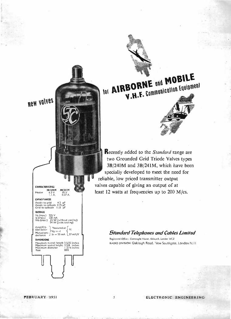
CHARACTERISTICS
3B/240M 3B/241M Heater 6.3 V 19 V
1.1 A, 0.37 A.
CAPACITANCES
Anode to grid 4.3 pF Anode to cathode 0.15 pF Grid to cathode 11.0 pF
RATINGS
Va (max.) 325 V la (max.) 120 mA Wa (max.) 15 W (without cooling)
24 W (with cooling)
AmPlin '1- Measured at tion factor t j 90
Vg = -I Mutual con-ductance j la 50 mA 27 mA/V
DIMENSIONS
Maximum overall length 3.5/32 inches Maximum seated height 2.5/8 inches Maximum diameter 1.3/16 inches Base B8B
FEBRUARY 1951
t AIRBORNE gild MOBILE, tommunitniion Equipment
Recently added to the Standard range are
two Grounded Grid Triode Valves types
3B/240M and 3B/241M, which have been
specially developed to meet the need for
reliable, low priced transmitter output
valves capable of giving an output of at
least 12 watts at frequencies up to 200 M/cs.
5tandard Telephones and Cables Limited Registered Office: Connaught House, Aldwych, London WC2
RADIO DIVISION Oakleigh Road, New Southgate, London N. II
5 ELECTRONIC ENGINEERING

CLASSIFIED ANNOUNCEMENTS (Coned)
ASSISTANT Mechanical Engineer required by large well known firm to undertake mechanical design of interesting new electro mechan.cal equipments. The work will be varied and the prospects good. Apply quoting ref. DIH to Box No. W 2686.
NELSON RESEARCH Laboratories, English Electric Co., Stafford, have vacancies in their laboratories for men interested in experimental and theoretical work on small transformers and other allied iron core devices. This work will include the study of the behaviour of trans-formers, etc.. under transient and steady A.C. conditions. Preference given to men with good Honours Degree in Physics or Engineering, in-terested in experimental work. Experience in this field desirable but not essential. Salary according to qualifications. Apply, stating age, qualifications and experience, quoting Ref. 821, to Central Personnel Services, English Electric Co., Ltd., 24-30 Gillingham Street, London, S.W. I . W 2679
RADAR, Radio and/or Electronics Senior Development Engineer wanted for work on important defence project in special English Electric Company Laboratory. Salary, f6C0-£900 per annum, according to experience. Write, giving details of qualifications and previous ex-perience, mentioning Ref. 456A, to Central Personnel Services, English Electric Co., Ltd., 24-30 Gillingham Street, London, S.W.I.
W 2678
TEST ENGINEERS required for design and manufacture of apparatus for production testing of Radar, Communications, and Electronic Equipment. Salary according to qualifications and experience. Full details to the Personnel Manager, E. K. Cole Ltd., Malmesbury, Wilts.
W 2676
E. K. COLE LTD., have vacancies, in their Electronics Division at Malmesbury, Wilts., for Senior and Intermediate Draughtsmen in the Development Drawing Office, for work on Radar, Communications, and Electronic pro-jects. Previous experience in this field desirable but not essential. Apply, in writing, to the Personnel Manager, Ekco Works, Malmesbury, Wilts, W 2677
SCIENTIFIC GLASSBLOWER for Vacuum Physics Laboratories, experienced in high vacuum work and knowledge of glass and metal seals an advantage but not essential. Interest-ing work in ideal conditions and surroundings. Permanent staff position. Apply, stating salary expected and giving full details of training. qualifications and experience, to Personnel Officer, Ferranti Ltd., Ferry Road, Edinburgh.
W 2674
VACANCIES exist for Electro-Mechanical De-signers used to engineering the mechanical side of communications and similar projects, and also associated with heavy mechanisms. A good degree on Mechanical and Electrical Engineer-ing or similar qualification is desirable as well as several years' experience in a Laboratory or Factory design department. Salary according to qualifications. Apply to Personnel Officer, Mut-lard Electronic Research Laboratory, Salfords, Nr. Redhill, Surrey. W 2630
HIGH FREQUENCY Induction Heating Ap-plications Engineer required by progressive and expanding company specialising in the manu-facture of high frequency equipment. Ex-perience in induction heating essential and a good knowledge of metallurgy would be con-sidered as an additional qualification. The position offers excellent opportunities for advancement to a really energetic man having the requisite experience. Write giving ex-perience and salary required to Box No. W 1213.
FERRANT! LIMITED have vacancies in their Radio Works, at Moston, Manchester for Radio/Television Design Engineers, both senior and junior. Generous scale of payment, ex-tending liberally into the four figure range, according to qualifications and experience. Permanent staff, appointments with super-annuation benefits. Forms of application from The Staff Manager, Ferranti Ltd., Hollinwood, Lancs. Pease quote reference R.E. W 2617
INTERESTING vacancies exist with the Nelson Research Laboratories of the Eng'ish Electric Co. Ltd., for university trained elec-tronic engineers or physicists with an interest in the design of special circuits for computing machines. These vacancies are at Stafford and in the London area and offer scope for original work in this interesting field. Write giving full details mentioning reference 305A to Central Personnel Services, English Electric Company Limited, 24-30, Gillingham Street, London, S.W.1. W 2621
RADIO VALVE ENGINEERS. The M.O. Valve Company have vacancies for qualified engineers in connection with the development manufacture and application of radio valves. Please apply by letter stating particulars and salary required to Personnel Department. The M.O. Valve Co., Osram Works, Brook Green, Hammersmith. W 2624
COIL WINDER required for interesting de-velopment work on a wide variety of coils and transformers. The applicant should have had at least three years experience of factory methods on small tranformers and wave wound coils. A knowledge of design and testing methods would be an advantage. Staff appoint-ment, salary according to qualifications. Apply to Personnel Officer, Mullard Electronic Re-search Laboratory, Salfords, Nr. Redhill, Surrey. W 2629
A VACANCY occurs for a Senior Draughts-man of at least H.N.C. standard for layout work, on interesting electro-mechanical projects. Salary according to qualifications. Apply to Personnel Officer, Mu!lard Electronic Research Laboratory, Salfords, Nr. Redhill, Surrey.
W 2628
AN EXPERIENCED Valve Engineer is required for employment at Chelmsford. Applicants should be 25-35 years of age, qualified engineers and preference will be given to those with previous design or production experience of small transmitting valves. Write giving full details of experience mentioning ref. 497C to Central Personnel Services, English Electric Co. Ltd., 24-30 Gillingham Street, London, S.W.I.
W 2632
APPLICATIONS are invited from men aged 21-40 years for work of a permanent nature which offers considerable scope for advance-ment. Applicants should have experience in the development and construction of Laboratory Test or Instrumentation Equipment or Sub-Miniature U.H.F. Gear. Ordinary or Higher National Certificate or C. and G. Telecom-munications (Parts II and III) desirable. Salary commensurate with qualifications and ex-perience. Apply to Box No. W 2637.
MURPHY RADIO LTD.. having recently ex-panded their Electrical Design Department in-vite applications from television and radio engineers having good academic qualifications (Honours Degree in Physics or Electrical Engi-neering) and experience in industrial design Laboratories. There are also openings for graduates trained in these branches, but with-out industrial experience. Applications giving full particulars of training and experience should he forwarded to: Personnel Department, Murphy Radio Ltd., Welwyn Garden City, Herts. W 2639
MARCONI'S WIRELESS TEI.EGRAPH Co. Ltd., have vacancies for Junior Engineers to work on VHF Transmitter Development and Multiplex Channelling. Candidates should have a Degree in Physics or Electrical Engineering or equivalent qualifications, or should have had good experience on radio development or re-search. Experience on VHF or Multiplex Chan-nelling is desirable. Good salaries will be paid, based on qualifications and experience. The Company has a Staff Pension Fund. Apply giving full details quoting ref 822A. to Central Personnnel Services, English E'ectric Co. Ltd.. 24-30 Gillingham Street, London, S.W.I.
W 2641
A NUMBER of Senior and Junior vacancies for Radio, Radar, Electronic, Television, etc., Development, Service Engineers, Draughtsmen, Wiremen, Testers, Inspectors, etc. Urgently required, 30 Television Service Engineers. Write in confidence: Technical Employment Agency, 179 Clapham Road, London, S.W.9. (BRIxton 3487.) W 113
RADIO-RADAR Development, Engineers ur-gently required, accommodation available. Appli-cations are invited from Senior and Junior Development Engineers, preferably with ex-perience of Radar or microwave technique, who are capable of developing equipment or compo-nents to Service Specifications. Successful candi-dates will be employed on work of great National importance. Write quoting reference Cl-IC (5) to Personnel Officer, General Electric Co. Ltd., Radio & Television Works, Spon Street, Coventry. W 2642
SITUATIONS WANTED
ELECTRONICS ENGINEER, B.Sc.(Hons. Eng.), 27, administrative, drawing office, instrument and electronic development, and design experience, seeks responsible post. Box No. W 1234.
EXPERIENCED development engineer (elec-tronics) seeks active partnership in existing firm or new enterprise. Capital available. Box No. W 1236.
GRADUATE, 5 years' experience in D.C. ampli-fiers and servos, seeks development post in medical (or similar) electronics. Box No. W 1244.
GLASSBLOWER, 20 years' experience hard and soft glass, electronic devices, vacuum circuits, glass-to-metal seals, chemical apparatus, etc. Box No. W 1245.
MECHANICAL AND ELECTRONIC Engineer, G.I.Mech.E., age 26. Experience includes work-shop training, administration, failure investigations, sales promotion, and sales information services. Seeks job connected with electronics and calling for initiative, enthusiasm, inventiveness, and systematic approach. South of England 'preferred. Please write fully to Box No. W 1247.
FOR SALE
AMERICAN MAGAZINES. One year post free. "Radio Electronics." 32s. 3d.; "Audio Engineering," 28s. 9d.; "Radio and Television News," 36s.•, "Popular Science," 28s. 6d. S.A.E. for full list from Willen Ltd.. (Dept. 9). 101 Fleet Street. London. E.C.4. W 108
GLASS-TO-METAL SEALS and High Vacuum by Hall, Drysdale & Co. Ltd., of 58 Commerce Road, Wood Green, London, N.22. 'Phone: BOWes Park 7221. W 117
COILS. Special inductances 1p,H to 2H at RF, singly or quantity, wound to order. Bel Sound Products Co., Marlborough Yard, Archway, N.19. Archway 5078. W 112
WEBB'S 1948 Radio Map of World, new multi-colour printing with up-to-date call signs and fresh information; on heavy art paper, 4s. 6d., post 6d. On linen on rollers, lis. 6d., post 9d. W 102
MERCURY SWITCHES are made by Hall Drysdale & Co. Ltd., of 58 Commerce Road, Wood G•een, London, N.22. Phone BOWes Park 7221-2. W 107
G. A. RYALL, " Utopia," Mayfield Road, Herne Bay, Kent, offers Post Free Bargains. Instrument boxes, metal, thick gauge, black finish, size fP.- in. by 71 in. by 31 in. deep, with paxolin lid, 1-in. fixing lugs for wall or bench, and corner sockets for panel fixing, 6s. 9d. each. Meters, 21 in. or 31 in. overall, flush type front fixing, 0-30 mA, good make m/c., 5s. 9d. And 0-300v, 2-in, size, square front ditto, sepa series res. FSD 5 rnA, 5s. 9d. each. Miniature instrument switches 2P, 6W, Is. 3d. 3B, 2P, 6W five-pole, total Is. 6d.
W 1239
CLASSIFIED AN continued on Page 8
ELECTRONIC ENGINEERING 6 FEBRUARY 1951

3
A new
MINIATURE â
.\ a
a
voltage
• a Reference
‘Tube
Designers of compact industrial equipments will welcome this new Mullard
Miniature Voltage Reference Tube. Built on the small B7G base, it is characterised
by high stability and robust construction. It should prove of great value where an
extremely accurate and reliable performance, coupled with a maximum saving of
space, is required. The larger version of this tube known as the 85AI built on a B8G
!octal base is also freely available.
Working in a constant current circuit, these tubes provide a voltage source
of extremely high constancy, and in the majority of applications may be used to replace
a standard cell as a built-in source of voltage reference. They may likewise be used
as a reference against which to compare or fix the level of almost any physical
quantity which is convertible into an e.m.f.
Their use in this manner in position control
systems, temperature control devices, etc., will
thus be apparent.
Mullard THERMIONIC VALVES AND ELECTRON TUBES
VALVE DATA
Nominal Operating
Voltage
Max. Starting Voltage
Current Range
Operating Current
Internal Resistance at
4-5mA
85V
i 25V
I-8mA
4.5mA
290 ohms
INDUSTRIAL POWER VALVES THYRATRONS INDUSTRIAL RECTIFIERS PHOTOCELLS
FLASH TUBES ACCELEROMETERS • CATHODE RAY TUBES • STABILISERS AND
REFERENCE LEVEL TUBES COLD CATHODE TUBES • ELECTROMETERS, ETC.
MULLARD ELECTRONIC PRODUCTS LTD., CENTURY HOUSE, SHAFTESBURY AVENUE, LONDON, W.C.2
mv-r sexy
FEBRUARY 1 9 5 1 7 ELECTRONIC ENGINEERING

CLASSIFIED ANNOUNCEMENTS (Coned.)
HORIZONTAL glass-working Lathe, 12-ft bed. I2-in. centres, complete with three movable heads and also fire carriages. Further particulars, S.T. &,C., Ltd., Ihninster, Somerset. W 1240,
" ELECTRONIC ENGINEERING," January, 1947-May, 1950 inc., also odd copies " Television," Oct. and Dec., 1934, July, 1935. Offers? G. Short, Fowlmere, Royston, Herts. W 1233
MAGSLIPS at 1/10th to 1/20th of list prices. Huge stocks. Please state requirements. K. Logan, Westalley, Hitchin, Herts. W 116
PROF. KITAI'S ingenious valve voltmeter, assem-bled complete, 12 gns. Coils, transformers wound, singly or quantity. Bel Sound Products Co., Marlborough Yard, Archway, N.I9. ARC. 5078.
W 2698
BARREL PLATING capacity available. Cad-mium, copper, tin, and electro-galvanizing. Packer & Son, Sion Place, Clifton, Bristol, 8. 'Phone : 38368. W 1246
RUBY STYLUS, .0027-in, radius for E.M.I. Lightweight Pickup. Every one shadow-graphed. Price : 4s. 8d., plus purchase tax, Is. 10d. Cash with order. Bradmatic, Ltd., Station Road, Aston, Birmingham, 6. W 2699
NEW BOXED VALVES, fully guaranteed. 5Z4, 6X5, 6K7, 6K7GT, EBC33, 12A6, 6M7, VRI37, 9D2, 105, DDL4, 6SK7, 6AC7, 7Q7, 37, E132, EK32, EC52, VR54, VR57, EF36, 6J7, 5s. 9d. each. 6Q7G, 6Q7GT, EF39, 5U4G, 6C5, 6C6, 6D6, 807, VR150/30, 7Q7, 6V6, 5Y4, 77, 78, 6s. 6d. each. 1S4, 1S5, IRS, 3S4, 1T4, 7s. each. Send for lists. C.O.D. or C.W.O. Carriage paid. Alpha Radio Supply Co., 5-6, Vinces Chambers, Victoria Square, Leeds, 1. Post orders only.
W 2647
SERVICE
ELECTRICAL Measuring Instruments of every make repaired and standardised. The Electrical Instrument Repair Service, 329 Kilburn Lane, London, W.9. Tel: Lad, 4168. W 2675
SPEAKERS reconed and reconditioned. Wave-wound Oscillator, Aerial and I.F. Coils re-wound. Transformers, Fields, Armatures re-wound. H. Davies, A.M.I.P.R.E., Radio & Transformer Services, Church Hill, Connah's Quay, Chester. W 2680
TRANSFORMERS, Chokes and Coils. Quan-tities of one dozen or more at keen prices. Good delivery. Ruskill Products Ltd., Kings-wood Works, Pitsea, Essex. Phone: Vange 3124. W 1216
GLASSBLOWING. repetition and scientific, by Hall Drysdale & Co. Ltd., of 58 Commerce Road, Wood Green, London, N.22. Phone BOWes Park 7221-2. W 109
EDUCATIONAL
THE POLYTECHNIC, 309, Regent Street, W.I. Electrical Engineering Department, Head of Department : W. H. Date, B.Sc.(Eng.), M.I.E.E. A special course of four lectures on Ultrasonics and its Applications in Industry will be given by L. I. Farren, M.B.E., Whit.Schol., M.I.E.E., DIC., Member of the Staff of the Research Laboratories of the General Electric Co., Ltd., on Fridays at 6.30 p.m., commencing March 2nd, .1951. Fee for the course, 10s. A syllabus may be obtained on application to the undersigned. J. C. Jones, Director of Education. W 2683
Partrície'lliews3
precision TRANSFORMERS " TO SPECIFICATION" or
STANDARD, if the problem is Trans-
formers or Chokes, none are more
experienced to find the solution than
Partridge. Nearly two decades cf specialised
research and production have prompted
leading industrial concerns and Govern-
ment Experimental Stations consistently to
use the unequalled Partridge service. Your
need, too, can be adequately met for
transformers ranging from 5 VA to 50 kVA
-power or A.F. Send for catalogue
and data sheet..
* Note: All Partridge components are now available
HERMETICALLY SEALED IN OIL
PARTRIDGE TRANSFORMERS LTD
ROEBUCK ROAD, TOI WORTH
rtieil0fIC
KINGSTON -BY -PASS SURREY
ELMbridge 6737-8
Ihi iospares•
Quality Parts
The Service Engineer's
First choice
SERVO CONTROL EQUIPMENT
MAGSLIPS Resolvers, Transmitters. Hunters Receivers etc., 2" and 3' types.
SELSYNS Power and Phase-Shifting types.
INDUCTION MOTORS AND VELODYNES
Send for list and technical details.
Repair facilities for all types of British and American Magslips, Selsyns, test equipment,
etc.
HOPTON RADIO, I, Hopton Parade, Streatham High Road,
LONDON, S.W.16.
'phone : STReotham 6165
CITY AND GUILDS. (Electrical, etc.) on 'No Pass-No Fee' terms. Over 95 per cent Successes. For full details of modern courses in all branches of Electrical Technology send for our I76-page handbook-Free and post free. B.I.E.T. (Dept. 337c), 17 Stratford Place, London, W.I. W 123
E.M.I. gave the world electronic television. E.M.I. is now giving the finest home study television courses. Moderate terms facilities for easy payment. Free brochure giving details on applica-tion to the Registrar, Dept. EE7, E.M.I. Institutes, 10, Pembridge Square, London, W.2. Bayswater 5131/2. W 2689
WANTED
WANTED, Coherers, Fleming Valves, Lieben-Reisz Relay, Round's Type " C," " T," " N," and "CA" valves, Langmuir Pliotron, early post-office repeaters, Marconi-Osram four-electrode and Type M.T.3 valves, Siemens-Halske Schottky tetrode, French " Horned" or " Kamerad," White and Lowe Multiple valves, also other early vacuum tube specimens to augment a personal historic collection. Full details and price, etc., to P. Kailus, 4625, Clausen Avenue, Western Springs, Illinois, U.S.A. W 1241
BEST OFFERS for (or offers invited) Cossor Double Beam Oscillograph. Model 1035. Model 1049 purchased for D.C. tests. Box No. %V 2688.
PATENTS
IT IS DESIRED to secure the full commercial development in the United Kingdom of BritishPatent No. 594,799, which relates to "Telemetering Systems" either by way of the grant of licences or otherwise on terms acceptable to the Patentee. Interested parties desiring copies of the patent specifications should apply to Stevens, Langner, Parry & Rollinson, 5 to 9, Quality Court, Chancery Lane, London, W.C.2. W 2658
TRANSFORMERS for
QUALITY, PERFORMANCE AND RELIABILITY
A wide range available for every Radio and Television purpose.
EP. 70 SHIELDED MAINS
EP. 90 SEMI-SHIELDED MAINS
EP. 76 STEP-DOWN MAINS
EP. 87 AUTO MAINS ...
DP. 61 HEAVY DUTY OUTPUT ...
39/6
39/6
41/3
34/9
49/6
Full range sent on application.
Special components supplied for Home Built Televisors
OLIVER PELL CONTROL LTD cao,,,51,t RDW sassact ROAD.. 5.E.I 8.
7'./.0ron, Woole..ch 1422
ELECTRONIC ENGINEERING 8 FEBRUARY 1951

Mr. Test
Terminal hermetically sealed:
two pronged soldering tag.
Robust bakelite case: maxi-
mum path between terminals
to avoid possible flash-over.
Series wound element: con-
servatively rated to provide
ample safety margin.
"Visconol" impregnation and
filling for safe H.V. working;
prevents arcing or brushing.
Hermetic sealing on to special
gasket avoids reliance on
soldered joints.
Sturdy one-hole fixing.
Suitable for use in conditions
of tropical humidity.
The unique design of these chassis-mounting Condensers
renders them eminently suitable for television and
allied high voltage applications up to 50,000 v. where exceptionally
stringent conditions are likely to be encountered. They are
processed with the newly developed impregnant "Visconol ", which
affords the advantages of adequate voltage
rating and low power factor, whilst improv-
ing the stability of the dielectric and its
power to withstand sharp-front short-time
surges. Wide range of working temperature,
—40 C. to +71'C., ensures reliable operation
under most stringent conditions. :111111111I'
`VISCONOL' CATHODRAY CONDENSERS THE TELEGRAPH CONDENSER CO. LTD • RADIO DIVISION • LONDON • W.3 • Tel: Acorn 0061 (9 lines)
FEBRUARY 1951 9 ELECTRONIC ENGINEERING
1
' 111111111111111111111 tâ•
Vit e 0
,..animeme» d
1-"" IT /4
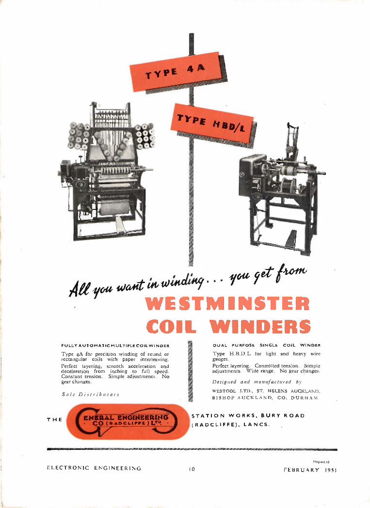
All re «Jae 14' uns etlesife • • • re eD /um' WESTMINSTER COIL WINDERS
FULLY AUTOMATIC MULTIPLE COIL WINDER
Type 4A for precision winding of round or rectangular coils with paper interleaving.
Perfect layering, smooth acceleration and deceleration from inching to full speed. Constant tension. Simple adjustments. No gear changes.
THE
Sole Di t ib 1( TO S
DUAL PURPOSE SINGLE COIL WINDER
Type H.B.D L for light and heavy wire gauges.
Perfect layering. Controlled tension. Simple adjustments. Wide range. No gear changes.
Designed and manufactured by
WESTOOL LTD., ST. HELENS AUCKLAND.
BISHOP AUCKLAND, CO. DURHAM.
EN ERAL ENGINEERING is. • •
STATION WORKS, BURY ROAD CO RADCLI rrE .1 LT°. (RADCLIFFE), LANCS.
ELECTRONIC ENGINEERING I
Hopwo Id
FEBRUARY 1951

Where excellent quality reproduction is essential . .
. . the Metrocick
AUDIO AMPLIFIER is the instrument to use
This instrume,nt is designed to give excellent quality reproduction with the added advan-tages of being a self-contained unit, portable and attractive in appearance. Thus it will prove ideal for Public Address work, educational authorities and similar organisations.
Supply:
Input:
Impedance: Output: Tone Control Response: Controls :
Dimensions: Finish:
SPECIFICATION 200/2 soV so cis single-phase; consumption approximately 170 VA for full output. Gramophone o•2V for full output. Microphone o•o2V for full output. The two circuits can be mixed as required. 7 ohms, s ohms and 4s ohms. 20 watts with negligible distortion. : Continuously variable. + ï dbfrom 30 to I s000 cis at zero position of tone control. These are recessed to avoid damage and are illuminated when in operation. ° A Qv/ , rf „ 2 ° 2 '
The instrument is housed in an attractive steel case, stove enamelled in cream or blue as desired. A leather carrying handle is fitted.
METROPOLITAN-VICKERS ELECTRICAL CO. LTD. TRAFFORD PARK, MANCHESTER 17
Member of the A.E.1. group of companies
TIETROVICK — Pioneers in radio and electronic equipment
I BRUARY 1951 11 ELECTRONIC ENGINEERING

e tip
For further details apply to
E.M.I. FACTORIES LTD. HAYES • MIDDLESEX
E199
Type 3794
An instrument designed to meet
television and radar test and research
requirements with comprehensive
facilities for the intimate study and
precise measurement of complex
waveforms.
TYPE 3794 OFFERS:
• Direct measurement of A.C., D.C.
or mixed voltages from 0.0$ to 500.
• Direct time measurement from 0.1
p, s. to 50 ms., with an effective hori-
zontal trace length variable to 50 cms.
• A wideband vertical axis amplifier
giving a time of rise of o.o8 s.
without overshoot on steep wave fronts.
• Dual input facilities with signal
gating.
ELECTRONIC ENGINEERING 12 FEBRUARY 1951

EDISWAN MAZDA 27M3 PHOTOMULTIPLIER, FOR
INVESTIGATIONS IN THE SPECTRAL RANGE 2200-6000 A.U.
The Ediswan Mazda 27M3 photomultiplier has
a special glass envelope which transmits ultra voilet radiation, and is
characterised by high sensitivity to ultra voilet as well as to the
visible region of the spectrum.
By the cylindrical formation of the secondary
cathodes or dynodes (see diag.) an exceptionally compact 9-stage
multiplier is obtained, in which, by a repeated process of secondary
emission, a very small photo current can be amplified by an average
of one million times, when the tube is operated at 100 volts per stage.
Since the secondary emission process occurs
instantaneously the frequency response is flat up to the frequencies,
above 108 c.p.s, at which transit time becomes a limiting factor. The
output current is also a linear function of the intensity of the
exciting radiation under normal operating conditions.
The cell is suitable for many applications
where investigations are required in the spectral range 2200 -
6000 A.U., e.g. for U.V, absorption measurements, spectrographic
and fluorescence analysis.
Incident Light
Diagram of
electrode structure,
TYPICAL OPERATION Voltage between anode and secondary
cathode kl0 50 volts
Voltage difference per stage 100 volt;
Max anode dark current (with 100 volte
between anode and cathode kl0)0.25 µA
Luminous sensitivity (taken on the
basis of a lamp colour temperature of
2700 °K and a light area of 4 mm x
20 mm) 10 amps/lumen
Current amplification (ratio of anode
sensitivity/cathode sensitivity) 10°
EDISWAN MAZDA
THE EDISON SWAN ELECTRIC CO. LTD., 1 5 5 CHARING CROSS ROAD, LONDON, W.C. 2
Members of the A.E.I. Group of Companies H.V.24
FEBRUARY 1951 13 ELECTRONIC ENGINEERING
The "Belling-Lee" page for Engineers
L7 I8/F WITH FLANGE
L7 I8/S WITH SKIRT
t630
LI274
IGNITION 7 SUPPRESSORS t
:/:
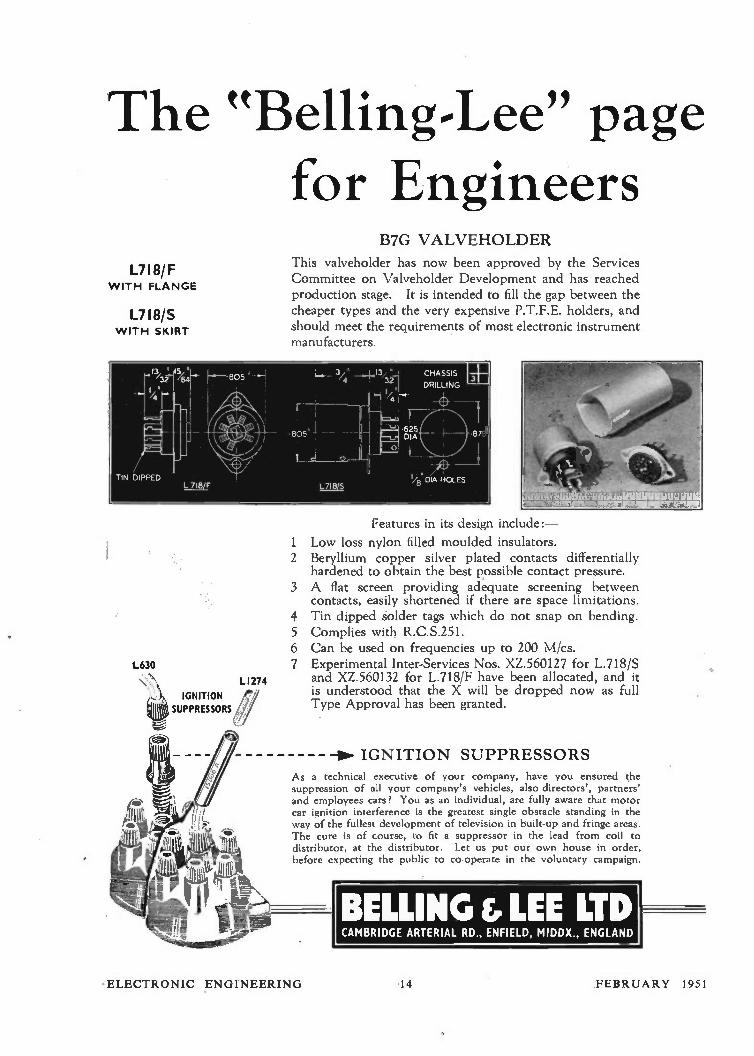
B7G VALVEHOLDER
This valveholder has now been approved by the Services Committee on Valveholder Development and has reached production stage. It is intended to fill the gap between the cheaper types and the very expensive P.T.F.E. holders, and should meet the requirements of most electronic instrument manufacturers
Features in its design include:-
1 Low loss nylon filled moulded insulators. 2 Beryllium copper silver plated contacts differentially
hardened to obtain the best possible contact pressure. 3 A flat screen providing adequate screening between
contacts, easily shortened if there are space limitations. 4 Tin dipped solder tags which do not snap on bending. 5 Complies with R.C.S.251. 6 Can be used on frequencies up to 200 M/cs. 7 Experimental Inter-Services Nos. XZ.560127 for L.718/S
and XZ.560132 for L.718/F have been allocated, and it is understood that the X will be dropped now as full Type Approval has been granted.
—IN. IGNITION SUPPRESSORS
As a technical executive of your company, have you ensured the suppression of all your company's vehicles, also directors', partners' and employees cars? You as an individual, are fully aware that motor car ignition interference is the greatest single obstacle standing in the way of the fullest development of television in built-up and fringe areas. The cure is of course, to fit a suppressor in the lead from coil to distributor, at the distributor. Let us put our own house in order, before expecting the public to co-operate in the voluntary campaign.
BELLING & LEE LTD CAMBRIDGE ARTERIAL RD., ENFIELD, MIDDX., ENGLAND
-ELECTRONIC ENGINEERING 14 FEBRUARY 1951

THE
Electronic Equipment
In the development and application of electronic
devices to meet the needs of industry BTH have
achieved considerable success. Products include:—
Emotrol variable speed motor control equipments,
Voltage Regulators, Marine Radar, High-frequency
Heaters (di-electric and induction types), Resistance
Welding, Photo-electric Relays, Process Timers, &
Sound-film (cine) Projectors: Magnetrons, Thyra-
trons, Ignitrons, and Rectifiers of all types including
Crystals, Spark Gaps, etc. Photo-conductive infra-
red cells, Mass Spectrometers, 8c Test Equipments
for industrial processes, etc. etc. The unrivalled
manufacturing resources of BTH backed by signifi-
cant contributions from its Research Laboratory
over a pioneering period of thirty years, are
available to progressive Management in any
industry wishing to improve product and output.
BRITISH THOMSON-HOUSTON COMPANY LIMITED, RUGBY, ENGLAND
A4I62
FEBRUARY 1951 15 ELECTRONIC ENGINEERING

FOR
HIGH-
FREQUENCY
INSULATION —
specify itro
I 'MEOW
Photograph by permission of the Standard Telephone & Cables Ltd.
The Coupling Coil shown is supported by our "FREouELEx" Ceramic Rods, and forms part of a zoo KW. Radio Transmitter. This is only one of many applications where Rods made to close limits are required. We specialise in the manufacture of Ceramic Rods and Tubes of various sections in several classes of materials over wide dimensional ranges. The principal materials are:
I. Porcelain for general insulation. 2. Frequelex for High Frequency insulation. 3. Permalex and Templex for Capacitors:
The degree of accuracy depends on the size of the Rod or Tube, but the standard degree of accuracy is outlined in the Inter - Service Component Manu-facturers' Council— Panel R Specification embodied in our Catalogue of Radio Frequency Ceramics, copy of which will be sent on request.
Large Rods up to 44" long and sk" square are used as supports for Tuning Coils, etc.
We shall be pleased to have your enquiries for all sizes of Tubes and Rods. Prompt deliveries can be given for most sizes.
utters LOW LOSS CERAMICS
BULLERS LIMITED, 6 Laurence Pountney Hill, E.C.4. Phone: MANsion House 9971 (3 lines). Grams: 'Hullers, Cannon, London'
8L3
ELECTRONIC ENGINEERING 16 FEBRUARY 1951

THE COSSOR DOUBLE BEAM OSCILLOGRAPHS
Here are some details of Model 1049 as illustrated: The Double Beam Tube presents two simultaneous independent traces over the full diameter of a 90 mm. screen, and provision is made for the measurement of both input voltage and time upon
the calibrated dials of the instru-
ment. The Oscillograph is par-ticularly suitable for obtaining
permanent photographic records using the Cossor Model 1428
Camera for which a Motor Drive Attachment Model 1429 is
available.
Can this
Instrument
solve a
problem
for you ?
Widely different industries are daily finding new uses for
the COSSOR Double Beam Oscillograph. Sometimes it
provides the answer to an industrial problem of long
standing. The tracing and measurement of noise, strain
and vibration are typical everyday applications of this
versatile instrument which is already helping engineers in
industries as far apart as brewing and the manufacture of
jet engines. Call on our technical advisory staff if you have
a problem. They will quickly let you know whether the
Oscillograph can help you.
COSSOR Double Beam OSCILLOGRAPHS
Please address enquiries lo: A. C. COSSOR LTD., INSTRUMENT DIVISION (Dept.B BIGHBURY GROVE, LONDON, N.5.
Telephone: CANonbury 1234 (30 lines) CI.21
FEBRUARY 1951 17 ELECTRONIC ENGINEERING

FERRANTI TRANSFORMERS
'H' series hermetically sealed
'C' core transformers and chokes
Designed to conform to Specification R.C.S. 214 and R.C.L. 215. Fully
approved by the Admiralty, War Office and Air Ministry for use in
Service Equipment.
Designed to meet Customer's particular requirements. For quotations and
further information please write directly to :-
1
FERRANTI LTD • TECHNICAL SALES DEPARTMENT • FERRY ROAD • EDINBURGH,5
FERRANTI
ELECTRONIC ENGINEERING 1,; FEBRUARY 1951

One dog - One bone One man - one job
One plant - one purpose
One factory - one plant
Technicians with a
background of 25 years'
experience, working with
single-purpose plant
in a factory
designed for one object
produce nothing but
the high standard of
transformers
that bear the name • • •
IPARIMIEKO of LEICESTER Makers of Transformers for the Electronic and Electrical Industries
FEBRUARY 1951
D
Electronic Engineering
Incorporating
ELECTRONICS, TELEVISION
and SHORT WAVE WORLD .
Managing Editor, H. G. Foster, M.Sc., M.LE.E.
Vol. XXIII. FEBRUARY 1951 No. 276
In This Issue Commentary 43 The Measurement of High Vacuum by Electrical Methods—Part II. 44
By F. Wade
The Home-Built F.M. Receiver Reception Tests ... 49 By K. R. Sturley, Ph.D., M.I.E.E.
Electric Controllers for Laboratory Furnaces ... 51 By M. H. Roberts, B.Sc.
A Precision Electronic Tachometer ... 55 By S. W. Punnett, B.Sc., and H. G. lerrard, B.Sc.' A.Inst.P ' . Inverse or Reciprocal Scales from Linear Potentio-
meters A. F. Boff,
High-Speed Waveform Monitor The Effect of Pen-to-Paper Friction in Recording
Instruments ... By M. J. Tucker, B.Sc.
The Holme-Moss Television Transmitting Station ... A Choke-Coupled Phase-Invertor of High Accuracy
By R. A. Seymour and D. G. Tucker
A Null Method of Measuring the Gain and Phase Shift of Comparatively Low Frequency Amplifiers 65
By T. Baldw.n, A.M.I.Mech.E., and J. H. Littlewood, M.Sc.
A Simple Analogue Computar for Fourier Analysis and Synthesis ..' 67
By J. H. Bowen. B.Sc., and T. E. Burn•UP,
A High-Stability Simple High Frequency Audio Source ' « —' 69
By W. E. Brunt Letters to the Editor Electronic Equipment Book Reviews .. Notes from the Industry Meetings this Month • .
59
60
61
62 64
70 72 74 77 78
Published Monthly on the last Friday of the preceding month at
28 Essex Street, Strand, London, W.C.2.
Telephone CENTRAL 6565 Telegrams LECTRONING, ESTRAND, LONDON'
Subscription Rate: (Home or Abroad) Post Paid 12 months 26s. or $3.75 (U.S.)
Classified Advertisements, Page 1.
Index to ADVERTISERS, Page 40
19 ELECTRONIC ENGINEERING

Erniaisc (TRADE MARK)
LACQUER RECORDING
THE FINEST FOR LACQUER
DISC RECORDING
The "Emidisc" lacquer recording blank fulfils
the requirements of the most exacting stan-
dards of Broadcasting Authorities, Film and
Professional Recording Studios. It may be
used with confidence by the critical profes-
sional recording engineer and by the owner
of the most modest equipment.
Accurate engraving to the limits of the re-
cording equipment is ensured by these essen-
tial qualities and characteristics.
• SUPERIOR UPPER FREQUENCY RESPONSE Will record up to 20,000e.p.s. with appropriaterecordingequipment
• LOW NOISE LEVEL—Average figures: -45db. ref. level 1 cm. per sec. velocity. -63db. ref. level 8cm. per sec. velocity. (Cut at 78 r.p.m., 9r diameter using sapphire cutter with 16 micron bevel.)
O ANTI-STATIC Easy swarf clearance with brush or low power suet ion systems.
• LACQUER THICKNESS Constant over whole recording area.
BLANKS
FREQUENCY
SCALE
- — 25 c.p.s
- - - - 100 c.p.s.
-- 200 c.p.s.
----250 c.p.s.
" Crossover frequency")
- - - - 1000 c.p.s.
10.000 c.p.s.
- - - - 15.000 c.p.s.
- - - 20.000 c.p.s
Buchmann dc Meyer pattern of a gliding tone, 20 Kilocycles
to 25 cycle8 recorded by E.M.I. Studios Ltd., on an Emiclik blank (Actual photograph).
• GOOD WEARING QUALITIES
• PROCESSING Mirror-like surface ensures ideal condition for processing (on appropriate sizes of blanks).
• PACKED IN HERMETICALLY SEALED METAL CONTAINERS Ensures good shelf life and protection. 10' sizes and upwards have individual air separation of blanks.
Types and Sizes available for all purposes
GREEN LABEL "Standard" selected direct recording blank -6", 8", 10", 12' and 16' sizes.
YELLOW LABEL " General Purpose" direct recording blank—lo-, 12- and 16' sizes.
PLAIN LABEL "Audition" direct recording blank for experimental and general testing work-10" and 12' sizes.
SILVER LABEL "Process". The blank for processing-11', 12', 13- and 17' sizes.
Manufactured in Great Britain under exclusive licence from PYRAL S.A.R.L. France.
WRITE FOR FULL PARTICULARS TO :—
E.M.I. SALES & SERVICE LTD IIMYGtlfu IliCrPre f. »U54.4: 1.11)..M.M5 no
DOMESTIC RECORDING EQUIPMENT DIVISION HIA0 OFFICE: HAYES • 14110DiEbEX • ENSLANO
ELECTRONIC ENGINEERING 20
11.1.21
FEBRUARY 1951

Electronic Engineering
Vol. XXIII. FEBRUARY 1951
Commentary Q IR WILLIAM HALEY, Director-General of the OB.B.C., at a Press conference on December 15th last confirmed the plans already announced for what might be termed the Five-Year Plan for the expansion of the B.B.C.'s Television service.
Details of the proposals, which include considerable ex-pansion in studio equipment and facilities, are to be found in the Annual Report of the British Broadcasting Cor-poration 1949-50 (H.M.S.°. 3s.) to which we referred editorially in the November issue of ELECTRONIC ENGINEERING. According to Sir William Haley, the capital expenditure
over the next three years for the development of television will amount to £4,250,000 representing 60 per cent of the Corporation's income, and the timetable for the comple-tion of the new main transmitters will be:—
Holme Moss (35 kW)—North of England Mid' 1951 Kirk o' Shotts (50 kW)—Central Scotland End 1951 Bristol Channel (50 kW)—Wales and West of England
micr 1952 to be supplemented by five low power transmitters as follows:—
Newcastle 1952 Southampton 1952 Aberdeen 1953 Belfast 1953 Plymouth 1954
This project which was initiated by the opening of Sutton Coldfield in December 1949 is thus expected to be completed by the end of 1954 by which time a coverage of 85 per cent of the total population will be obtained. There will still be some areas, notably East Anglia and the North of Scotland where satisfactory reception is problematical, but even so it is stated that this represents the highest service in the world.
Based on this coverage the number of television licences is expected to grow from the present 600,000 to 1,575,000 by April 1953 and it is anticipated that the radio industry will have no difficulty in keeping pace with the demand for television receivers, provided of course that the re-armament programme does not effect the position.
This rate of growth in the number of television licences appears however to be unduly conservative, and almost pessimistic for it implies that if there are on an average four viewers for every set—which is probably on the high side—then only 6,000,000 or 1/7th of the population living in the service area will be viewers by April 1953. This contrasts very unfavourably with the position of sound broadcasting with its near saturation figure of 12 million licences. There may be some dissatisfaction over the programme
No. 276.
material, and indeed grousing about the television pro-grammes has almost developed into a national pastime, but there can be no complaint regarding the technical achievements in some of the recent outside broadcasts or in the performances from the Lime Grove studios. More-over, it is well known that the present 405 line system still gives the best possible picture when all the conflicting requirements are taken into account, and requires at the same time a receiver with a minimum number of valves and components.
Q EVENTEEN years have elapsed since the Radio 1-7Research Board last published its annual report which was for the period January 1932 to September 1933. During that period considerable reorganization was
taking place which resulted in the amalgamation of the Wireless Division of the National Physical Laboratory and the Radio Research Station at Slough into what is now known as the Radio Division of the National Physical Laboratory with Sir Robert Watson Watt as its first Superintendent. • The Report of the Radio Research Board for the period October 1933 to December 1948 (H.M.S.O. 2s.) which has just appeared after this long interval is therefore very welcome and makes most interesting reading. The Board's Chairman, Col. Sir A. Stanley Angwin in a brief report of some ten pages modestly apologises for not publishing a report since 1933 " for a number of reasons of which the most important were the occurrence of the second World War and the concentration of the efforts of a large section of the staff of the Radio Division on defence projects of very great importance from 1935 on-wards," and in a delightful self-effacing manner dismisses the magnificent contributions to the war effort in no more than one page regretting that " there was some deflexion of effort from certain of the long-term projects to those of more immediate practical application." For the sake of continuity, the Chairman's report con-
tains reviews of the three periods (1) October 1933 to August 1939, (2) September 1939 to August 1945 and (3) September 1945 to December 1948.
In the remaining 50 pages of the Report, Dr. R. L. Smith-Rose, the Director of Radio Research, contributes a more detailed survey of the investigations carried out during the years 1934-47 and concludes with his report for the year ended December 1948. The present research programme contains 15 major
items covering, in the main, the study of the ionosphere and the propagation of radio waves throughout the whole effective radio spectrum.
FEBRUARY 1951 43 ELECTRONIC ENGINEERING

The Measurement of High Vacuum by Electrical Methods (l'art 2)
By F. Wade *
Penning or Philips Ionization Gauge
BY using a discharge tube of special construction in con-junction with a permanent magnet, Penning" was able
to measure pressures down to 10-5 mm Hg. The discharge tube, (Fig. 14) consisted of two flat plates forming a common cathode and interspaced between these plates is a wire loop, this being the anode. With suitable potentials and no magnetic field the elec-
trons emitted from plates p, and P, will travel towards the ring R. If a magnetic field of sufficient strength be applied in a direction perpendicular to the plates the electrons will move towards R in a spiral motion about the axis of the magnetic field. The electrons emitted from P, will travel in the direction of P, where they. are repelled and return to the direction of P,. This process is repeated several times before the electron finally comes to rest, thus the distance travelled by an electron is greatly increased, thereby increas-ing the probability of ionizing a gas molecule. The Penning gauge is connected as shown in Fig. 15.
For qualitative measurements only, the length of glow in the neon indicator is used; when quantitative measurements are required, the current recorded on the microammeter is expressed as a function of pressure. A typical calibration curve is shown in Fig. 16.
Fig. 14. Philips gauge
Triode Ionization Gauge
The possibility of using a triode thermionic valve as an ionization gauge was first reported by Buckley." Soon afterwards Simon" revealed that a .triode valve had been used in this manner with considerable success in the labora-tories of the " Telefunken Gesellschaft." Since these first reports this type of gauge has become one of the most used high vacuum measuring devices.
In the triode ion gauge the source of the electrons is an incandescent cathode. Ionization takes place in the inter-electrode space due to the collision of electrons with gas molecules, the positive ion current being collected by the negative electrode. There are two methods of operating the gauge and they are generally classified as A and B. In method A the grid is made negative to cathode, while the anode is maintained at a high positive potential, thus the grid becomes the collector and the anode is the accelerator. In method B the functions of the electrodes are reversed, i.e., the grid is positive and the anode negative. Method B has been found to be the more sensitive due to the fact that the electrons oscillate about the positive grid with the result
• Atomic Energy Research Establishment. Harwell.
that the path taken by the electron is greater than in method A.
A complete mathematical treatment of the ionization gauge has been given by Kaufmann and Serowy." This is for method A only. Their work is based upon an empirical formula of Miller's":
p = k Igl Is d (14)
where p -= pressure
k = an empirical constant
/, = grid current
= anode current
d = distance between grid and anode.
Their investigations had the object of ascertaining the dependence of the magnitude of k on the potentials, both empirically and theoretically. For their experiments they used a valve with the usual concentric electrode arrange-ment where:
ri, = radius of filament wire
= radius of grid
r, = radius of anode.
and cathode, grid and anode voltages = Vi,;
'Mn PENNING I. — GAUGE
APPROX 2,000
0.1
pa METER
hg. IS. Philips gauge with indicator
NEON LAMP
They show mathematically that:
2 b(Va - V's) fr, r/(V)dl' (15)
where p = pressure
b - log. (r2/r1)
Vic = an imaginary charged surface of fictitious poten-tial 1/1,.* The second term was arrived at under the simple
1
*In the absence of space charge the action of the grid in a triode can be represented by the action of a conducting "Equivalent plane" in the same position as the mid-plane of the grid. The effective grid voltages in this plane are:
- DV. Vig 1 , , 1 ,
D[—Iniriv+ rul E - Vtirs, 1 , „ .. (17)
log, log, log, where D=11 m;
m= amplification factor For a more complete treatment of this subject the reader should consult the works of Dow," Chaffee", Liebmann", or any reference book on radio valve design.
ELECTRONIC ENGINEERING 44 FEBRUARY 1951

assumption that if the initial velocity of the electrons is zero and is therefore only affected by V, therefore the number of ions N. per unit path traversed will depend upon this value and on the density of the gas molecules and will thus be directly proportional to p.
Thus: N = P AV) (16)
Kaufman and Serowy state that as Vig can be replaced by known terms, it is possible to calculate the gas pressure for valves of known goemetry. The theoretical treatment of the use of the ionization
gauge in method B is far from complete. It is of a much more complex nature than when the gauge is operated as method A. This is mainly due to the fact that it is difficult to estimate the number of times that the electron oscillates about the grid.
In method B the anode of the valve becomes the collector and the grid by virtue of a high positive potential becomes the accelerator. In this mode of operation electrons will leave the filament and travel towards the grid. Owing to their high velocity and the open mesh of the grid, the majority will pass through and will continue moving to-wards the anode. At some point between the grid and anode they will reverse direction and travel back towards the grid. The majority will pass through the grid mesh and will travel towards the filament until they change direc-tion and begin the whole cycle again.
Reynolds39 has investigated this problem and has shown that it is possible to calculate the average number of journeys made by an electron. For his investigations he
200
100
2
02 0-5 1-0 20 513 10ems
lo
pst
20 50 100 200 METER READING ).so
Fig. 16. Ca ibration curse for Philips ionization gauge
SOO 1000
used an ionization gauge developed by Dushman and Found."
Fig. 17 shows the potential geometry relations for this gauge. Neglecting space charge it shows diagrammatically the distance that an electron travels and also the fields acting upon it. In the case taken, the electrodes are concentric cylinders and it is assumed that the radial fields are linear. The velocity of the electron at A' is determined by the value of the positive potential applied to the accelerator V.. If now Vi is the ionizing potential of the gas or,gases under investigation, then between the points A' and B' the electron will have sufficient energy to ionize a gas mole-cule. The point of reversal of the electron in the grid anode space is at D. Neglecting the space charge of the filament the electron will travel back again along the same path. There is, of course, the likelihood of the electron being collected at A', or it may continue to oscillate about the grid until it is finally collected. Therefore, the distance that the electron travels in which ionization can take place
is some multiple of 2 x A'B'. It has previously been shown in Fig. 7 that the probability of ionization will vary with the voltage applied to the accelerator as well as the gas under investigation. From this curve it is thus possible to approximate the probability of an electron producing a positive ion in one single journey between Ali'. This is done by integrating under the curve of Fig. 7 between the two defined limits y,. and Vi and then multiplying the resuk by the distance A'B'. The probability when multiplied by the value of the electron emission current fern will give a value for Pp, this being the positive ionization current pro-duced by a gauge at a pressure of 1 mm Hg. This is assuming that the electron traverses the distance A'B' only once.
Reynolds calculates the value of l'y by using a formukt of Thompson. The average number of times that an elec-tron traverses the grid anode space is given as:
Z = ) fern 1 — 02
20
where O = effective open area of grid
le. = electron emission current.
The calculated and measured values of I'„ did not agree and it was found necessary to introduce a correction factor of 3.9 to bring these results into agreement with each other.
(18)
Alphatron Gauge
The most recent of all types of vacuum gauges is the CRY
200
ISO
100
50
n
A!
t-
vi Ji
_ a'
q C-)
O 10 20 30 40 50 60 RADIUS R (mm)
Fig. 17. Potential geometry relationship for Dushman and Found ionization gauge (Reynolds)
Alphatron Ionization Gauge. This gauge contains a small radium source which emits alpha particles. Any gas mole-cules present in the gauge are ionized, thus the ionization current is a function of the pressure and can be expressed as such. The ion current is very small and it must be amplified on a high gain D.C. amplifier. Meier" has described a gauge and amplifier of this type and has given the working range of this gauge as 10-* mm Hg. to 25 mm Hg.
Knudsen Gauge
The only absolute vacuum measuring gauge that has been developed so far, that can be operated electrically, is that of Knudsen." The operation of this gauge is dependent upon the radiometer effect. This is an effect which occurs when a gaseous medium is at such a pressure that the mean free path is much greater than the vessel in which
FEBRUARY 1951 45 ELECTRONIC ENGINEERING
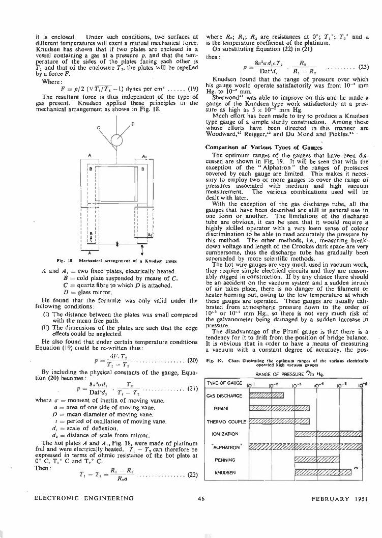
it is enclosed. Under such conditions, two surfaces at different temperatures will exert a mutual mechanical force. Knudsen has shown that if two plates are enclosed in a vessel containing a gas at a pressure p, and that the tem-perature of the sides of the plates facing each other is T, and that of the enclosure T2, the plates will be repelled by a force F. Where:
F = pI2 (V Till', —1) dynes per cm' (19) The resultant force is thus independent of the type of
gas present. Knudsen applied these principles in the mechanical arrangement as shown in Fig. 18.
1B 14
B
A
Fig. 18. Mechanical arrangement of a Knudsen gauge
A and A, = two fixed plates, electrically heated. Br---• cold plate suspended by means of C. C = quartz fibre to which D is attached. D = glass mirror.
He found that the formulœ was only valid under the following conditions:
(i) The distance between the plates was small compared with the mean free path.
(ii) The dimensions of the plates are such that the edge effects could be neglected.
He also found that under certain temperature conditions Equation (19) could be re-written thus:
4F. T2 P — — T2
By including the physical constants of the gauge, Equa-tion (20) becomes:
81r2o-d, T2 P (2 — I )
Dat2d, •T — 12 where a- = moment of inertia of moving vane.
a --- area of one side of moving vane. D = mean diameter of moving vane. t = period of oscillation of moving vane. = scale of deflexion.
dz = distance of scale from mirror. The hot plates A and A„ Fig. 18, were made of platinum
foil and were electrically heated. T, — T2 can therefore be expressed in terms of ohmic resistance of the hot plate at 0° C, T1° C and T2° C. Then:
T, — T2 — R, — R,
(20)
Roa (22)
where Ro; R1; R2 are resistances at 0% T20; T2* and a is the temperature coefficient of the platinum. On substituting Equation (22) in (21)
then:
p — Dat'd. • R1 — R2
Knudsen found that the range of pressure over which his gauge would operate satisfactorily was from 10-' mm Hg. to 10' mm. Sherwood" was able to improve on this and he made a
gauge of the Knudsen type work satisfactorily at a pres-sure as high as 5 x 10⁻² mm Hg. Much effort has been made to try to produce a Knudsen'
type gauge of a simple sturdy construction. Among those whose efforts have been directed in this manner are Woodward," Reigger," and Du Mond and Pickles."
8/r2crd,o.T2 Ro (23)
Comparison of Various Types of Gauges The optimum ranges of the gauges that have been dis-
cussed are shown in Fig. 19. It will be seen that with the exception of the "Alphatron" the ranges of pressures covered by each gauge are limited. This makes it neces-sary to employ two or more gauges to cover the range of pressures associated with medium and high vacuum measurement. The various combinations used will be dealt with later. With the exception of the gas discharge tube, all the
gauges that have been described are still in general use in one form or another. The limitations of the discharge tube are obvious, it can be seen that it would require a highly skilled operator with a very keen sense of colour discrimination to be able to read accurately the pressure by this method. The other methods, i.e., measuring break-down voltage and length of the Crookes dark space are very cumbersome, thus the discharge tube has gradually been superseded by more scientific methods. The hot wire gauges are very much used in vacuum work,
they require simple electrical circuits and they are reason-ably rugged in construction. If by any chance there should be an accident on the vacuum system and a sudden inrush of air takes place, there is no danger of the filament or heater burning out, owing to the low temperature at which these gauges are operated. These gauges are usually cali-brated from atmospheric pressure down to the order of 10 or 10-' mm Hg., so there is not very much risk of the galvanometer being damaged by a sudden increase in pressure. The disadvantage of the Pirani gauge is that there is a
tendency for it to drift from the -position of bridge balance. It is obvious that in order to have a means of measuring a vacuum with a constant degree of accuracy, the pos-
Fig. 19. Chart illustrating the optimum ranges of the various electrically operated high gauges
RANGE OF PRESSURE "Yrn Hg.
TYPE OF GAUGE - - 10-3 10 -S 1 •
GAS DISCHARGE
PI RANI
THERMO COUPLE
ION I ZATIO N
'ALPHATRON '
PENNING
KNUDSEN
_/727:27 Zi..727. 7 7 77--
r)
ELECTRONIC ENGINEERING 46 FEBRUARY 1951

sibility of drift from the balance position must be made as small as possible. This means that the bridge potential must be constant and that the walls of the glass bulb con-taining the Pirani gauge must be shielded from draughts and sudden changes of temperature. By immersing the Pirani gauge in liquid air the sensitivity can be increased, it is not normal laboratory practice to do this or to keep the gauge at the temperature of melting ice as sometimes recommended. The practical method of compensating for change of room temperature is that of Hale." With the thermo-couple gauge the great advantage is
that the millivolt meter can be connected direct to the thermo-couple, these readings can then be calibrated and expressed in terms of pressure. Thus the possibility of such things as drift of zero point are eliminated. To obtain greater sensitivity it is possible to use a bridge circuit and include a second thermo-couple gauge in the circuit, as is used in Hale's method of using a Pirani gauge. The current passed through the heater of the thermo-couple must, of course, be kept constant because with a sensitive thermo-couple slight alteration of the condition of the heater will cause a considerable increase or decrease in the thermal E.M.F. It can be seen from Fig. 6 that the range of the thermo-couple gauge is from approximately 10-1 to 10-`
VVV
The greatest advantage of the three electrode ionization gauge is that it can be subjected to the same heat treatment as the valve or tube that is being exhausted. This enables considerably more accurate measurements of the pressure to be recorded. If the gauge is not given the same treatment as the vessel that is being exhausted it may assist in either "cleaning up" the vacuum, thus acting as a getter, or it may reduce the quality of the vacuum when occluded gases are set free. This gauge also enables rapid changes in the pressure to be observed immediately.
It has been found by Blears," that the diameter of the glass tubulation that is used to connect the ionization gauge to the pump system is somewhat critical if it is desired to measure the pressure with accuracy. With a wide bore connecting tube the resistance which is offered to the entry of gases or vapours from the pump system is much less than that of a small connecting tube. This can be seen from the following equation:
W = l/r' (24)
where W = impedance of connecting tube / = length of tube. r = radius of tube.
--O ) 1 0--
o
1 o
VVV*
Fig. 20. Circuit of " Catbodeon ' combined Pirani and ionization gauge
mm Hg. At the extreme ends of the curve it will be seen that the calibration is very cramped. Under normal condi-tions the lower limit of the hot wire gauges is of the order of 10-s mm Hg.
The hot wire gauges have a very definite use when used in conjunction with another gauge which will measure the lower pressures. With the majority of these precision low pressure instruments, it would result in damage to the instruments if they were operated at pressures higher than 10-1 mm Hg. Thus the hot wire gauge gives an excel-lent indication when it is safe to switch on the more sensitive instrument. The three electrode ionization gauge when used in its
most sensitive mode of operation, i.e., method B, permits the measurement of these low pressures with comparative ease providing, of course, that the gauge has a good sensitivity.
The Penning or Philips gauge is very suitable for every-day industrial use as it is of a very simple construction and does not require any elaborate precautions to reduce shook or tremor. This gauge has the great advantage that it does not introduce any supplementary vapours of its own; this is due to the fact that while operating there is little or no temperature increase. The choice of the metal from which the cathode is made has some considerable influence upon the sensitivity of the gauge. The first cathodes were made of iron; later it was found that by using a more efficient source of emission such as zirconium or thorium not only was the sensitivity increased but the cathode sputtering that occurs at the higher pressures was reduced. Continual sputtering is detrimental to the life of the gauge, therefore special precautions have to be taken in the mounting of the electrodes, so that the possibility of the formation of leakage paths is reduced. This is usually done by placing
FEBRUARY 1951 47 ELECTRONIC ENGINEERING

glass sleeves over the electrode wires in the glass pinch upon which the gauge is mounted. By using mica disks to screen the lead-in wires small particles of metal may also be deflected away from the vulnerable areas. The " Alphatron " gauge appears to have several advan-
tages. Firstly, that it will work over a very wide range of pressures, secondly, that it has no hot electrodes and therefore does not cause any supplementary gases to enter the pumping system. The gauges that have so far been mentioned all suffer
from the same disadvantages in that they have to be cali-brated against some form of absolute gauge. The only form of an electrically operated absolute
vacuum gauge is the Knudsen. As shown in Equation (23), given certain information, the performance of the Knudsen gauge can be calculated. The disadvantages of this form of vacuum measurement
are many and it is not generally used except for calibration work. The gauge has to be mounted so that it is not sub-jected to mechanical shock or tremor. The torsion con-trol of the repulsion can give trouble at low pressures; this is due to the relatively large moment of inertia of the suspended system and the virtual absence of damping. If an external means of damping is employed there is a ten-dency for the zero point to drift. The one great advantage of this form of vacuum gauge is that it does not need different calibration scales for different gases. It also possesses the advantage that the temperature at which it operates is very low, this is particularly suitable for the measurement of pressures on large systems where organic vapours are present.
V-2
AMPERITE
R-4
Fig. 21. Combined thermocouple and Penning gauge circuit (Pickard-Smith and Zollard)
It has been shown that no one particular gauge can cover the complete range of pressures that are normally en-countered in medium and high vacuum work, i.e., 0.1 mm to 10-7 mm Hg., and so it is usual to use two or more gauges to do this. This introduces the undesirable features that more space is taken up by the ancillary electrical apparatus connected with each gauge. This has been over-come in special vacuum measuring equipment." In this invention the same electrical power supplies are used for both the medium and the high vacuum gauge. The medium vacuum gauge may take the form of a Pirani or thermo-couple gauge and the high vacuum measuring device is a three electrode ionization gauge. The electrical circuit is shown in Fig. 20 and from this it can be seen that by the use of a multibank change-over switch, either the medium or high vacuum gauges can be used. With the use of suitable shunts the same meters that indicate bridge current and out of balance current in the Pirani gauge may also indicate the electron current and positive ion current of the ionization gauge.
Provision has been made in this vacuum measuring unit so that the ionization gauge can be bombarded with elec-trons in order to degas the electrodes while on the pump. It is necessary to do this before any attempt is made te measure the pressure, otherwise a true indication of the vacuum will not be given due to the slow outgassing of the metal electrodes while operating.
Another instrument has been described" which consists of a thermo-couple gauge and a Penning ionization gauge. The circuit is shown in Fig. 21. By the use of the two pole three position switches, either the thermo-couple or the Penning gauge can be operated.
Conclusion The writer hopes that he has shown that the measure-
ment of low pressures is no longer an art but a science that has gradually been evolved from the " hit and miss" methods of the vacuum technicians and workers of the early 18th century. Like many other sciences its implica-tions are not always realized. There is nothing tangible to be seen from the work of the high vacuum engineer unless it is realized that without his efforts to create lowet pressures and the means to measure them, there would be no such things as radio telephony, radar, television and hundreds of other devices where therrnionic electron tubes are used. The writer would like to thank the Director of the
Atomic Energy Research Establishment for permission to publish this paper, and to Dr. G. Liebmann, of the Research Laboratories, A.E.I., Aldermaston, Berks., for the encouragement given to him in the preparation of a previous paper which has been condensed for the purpose of this article.
REFERENCES
' Hauksbee : Phil. Trans., 1705. I. 8 Monet and Morgan : " High Vacua," Kaye, 1879-85. Crookes : Phil. Trans., 1879-85. J. J. Thompson : " Conduction of Electricity Through Gases.'' • Pirani : Ver. d. Deutsch. Phys. Ges., 1906. Maxwell : Phil. Trans., 154, 49, 1867. Kundt and Warburg: Fogged. Ann. Phys., 156, 177, 1875. • Schleirmacher : Wiedem. Ann. Phys., 34, 621, 1885. " Bottomley : Proc. Roy. Soc., 37, 177, 1884. " Voege : Phys. Zeit. 7, 498, 1906. " Rohn : Zeits. f. Electrochem., 20, 539, 1914. " Rumpf : Zeiss. f. Tech. Phys., 5, 224. 1926. " Buckley Proc. Nat. Acad. Sol., 1, 683, 1916. " Misanuchi So. : Proc. Phys. Math. Soc., Japan, 1, 76, 1919. " Hausser-Gandswint and Rukop: Tel. Zig.. 1920. " Dustunan and Found : Phys. Rev., 17, 7, 1921. " Kaufman and Serowy : Zeus. f. Phys. 5, 319, 1921. " Simon : Zeits. f Tech. Phys., 5, 221, 1924. " Penning : Physica, 4, 71, 1937. " Meller : Electronics, April, 1946. " Soddy and Berry: Proc. Roy. Soc., 83, 254. 1910. " Hale : Trans. Amer. Electrochem. Soc., 1911. " Campbell : Proc. Phys. Soc., 33, 287, 1921. " Ellet and Zabel: Phys. Rev., 37, 1102, 1931. " Dushman : J. Franklin Inst., 211, 689, 1931. " Kovalenko : Tech. Phys. of U.S.S.R., 5, 779, 1938. " Dunlap and Trump : Rev. SM. Inst., 8, 37, 1937. " Compton and Van Voorhis: Phys. Rev., 23, 450, 1924. " Hughes and Klein : Phys. Rev., 26, 436, 1925. " Althenhum, Reger and Seeliger : Zeits. f. tech. Phys., 95, 161, 1928. " Carr : Proc. Roy. Soc., 81, 374, 1903. " Yarwood : Electronic Engineering, 16, 461'; 1944. " Stintzing : Z. Phys. Chem., 108, 70. 1914. " Moller : Die Electronrokren und ihre Anwendungen, 1920. " Dow : " Fundamentals of Engineering Electronics," 1937. " Chaffee : " Theory of Thermionic Vacuum Tubes," 1933. " Liebmann : 138, 1944. I' Reynolds : Physics. 1, 182, 1931. " Knudsen : Ann. d. Phys., 32, 809, 1910. " Sherwood : Phys. Rev., II, 143, 1918. " Woodward : Phys. Rev., 4, 419, 1914. 68 Reigger : Zeus. f Tech. Phys.. 101, 16, 1920. " Du Mond and Pickles : Rev. Se!. Inst., 9, 417, 1938. " Blears : Nature, 154, 20, 1944. " British Patent 574,798. " Picard, Smith and Zollers: Rev. SM. Inst. 17, 125 1944
General References
Dushman, S. : " High Vacuum." Kaye, G. W. C. : " High Vacua." Monch, G. " Vakuumtechnik im Laboratorium." Newman, F. H. : " Production and Measurement of Low Pressures." Goetz, A.: Physik und Technik des Hochvakuums. Strong, J. :" Modern Physical Laboratory Practice." Yarwood, J. : " High Vacuum Technique. ' Penning, F. M. : Philips Tech. Rev., July, 1937. Pirani, M. and Neumann, R. : Electronic Engineering, December, 1944.
ELECTRONIC ENGINEERING 48 FEBRUARY 1951

The Home Built F.M. Receiver Reception Tests
By K. R. Slurley, M.I.E.E. *
An experimental V.H.F. service is now being radiated by the B.B.C. from Wrotham, Kent, with simultaneous A.M. and F.M. modulation. The 25 kW F.M. transmitter is at present operating at 91.4 Mc/s and the 18 kW A.M. transmitter at 93.8 Mc/s from Monday to Friday from 11 a.m. to 4.30 p.m. with an hourly interval at mid-day and then from 6 p.m. onwards
until the close of the programme being radiated.
Since the design for the ELECTRONIC ENGINEERING " HOME BUILT F.M. RECEIVER" (Price 4/6) was first published in September, 1949, a considerable number have been constructed and satis-factory reports on its performance have been received. The Home Built F.M. receiver has a sufficiently wide range to tune to either of the transmitters and constructors may now wish to
convert the receiver for reception of A.M. signals.
THE experimental V.H.F. transmissions of F.M. (91.4 Mc/s) and A.M. (93.8 Mc/s) from the B.B.C. station
at Wrotham have given the author an opportunity of testing the performance of the home built F.M. receiver under normal conditions and it is thought that the results of the tests will be of interest to experimenters in this field. Modifications which were made to improve the performance of the receiver when operating on the fringe. of the service area are also described. The receiver was tested at two widely separated points,
one in Central London and the other at Evesham, about 20 and 110 miles respectively from the transmitter. The field strength over the London area is comparatively high and the test demonstrated little other than that the per-formance of the set is satisfactory under these conditions, that F.M. gives excellent suppression of impulsive inter-
To E C. C6 Valve
dB C17
Cia
R7
16 L3
RS R9
V3
Cis
V4
with reflector and director spaced as indicated in Fig. 50 (page 70) of the booklet was used on a chimney about 40 feet from the ground. A 20 feet coaxial cable con-nected the aerial to the receiver in a first floor room. A very satisfactory audio output was obtained with some background hiss due to thermal noise in aerial and receiver. The average value of signal at the input to the receiver appeared to be about 100 µV. The hiss, which varied in intensity, was generally only noticeable during breaks in the programme. Monitoring the limiter grid current showed that variations in signal strength occurred quite often but had little effect on aural output because of the high degree of limiting in the receiver. Occasionally,
HT. 300
REACTANCE CONTROL
PI VOLTAGE
C20 C25 HEATER
6V AC..
TC 2 2 'T 21 7 723
Ci9
Fig. A. Modifications to the original Fig. 17 to reduce hum level
ference and that the use of the wider A.F. band made possible by V.H.F. gives a great improvement in quality. The rendering of the higher frequency musical instru-ments is realistic and without the harshness and sibilence so often associated with any attempt to achieve a wider frequency response with the average broadcast receiver. The dipole described in Chapter VII was employed, set up in the same room as the receiver. The room, an office, was on a third floor, about 50 feet from a busy road. The main criticism of the receiver was on the score of hum level, which was perceptible during pauses in the programme.
At Evesham the site was favourable to the V.H.F. trans-mission, being on a hill facing the direction of Wrotham with five miles of comparatively flat country before a rise of 800 feet to the Cotswolds. A folded dipole aerial
• Head of B.B.C. Engineering Training Department.
ITUNING INEXCATOR
C24
19
T3
C20
R21 HY. 300V.
V3
, T4
A.F OUTPUT
C'
EARTH
Fig. 5. Main alterations to the existing circuit to permit A.M. reception
in the trough of a deep fade, noise formed a noticeable background to the programme. An aeroplane in sight of the aerial produced the well known flutter variation in signal and impressed a rhythmic variation on the noise background. A road ran parallel to the direction of Wrotham at a horizontal distance of approximately 40 feet from the aerial. Unsuppressed cars on this produced a faint "spitting" noise in the loudspeaker. The suppres-sion of impulse noise cannot be entirely satisfactory at this signal level because the limiter is not fully effective against noise peak amplitudes comparable with the signal. The need for correct tuning when signal strength is low
was seen, for noise was markedly minimum when the receiver was accurately tuned. The tuning indicator enabled this to be done quite easily and the A.F.C. action held the tuning point satisfactorily. As a result of the experience gained on these listening
tests, an appreciable reduction of hum and microphony
FEBRUARY 1951 49 ELECTRONIC ENGINEERING

and a worthwhile increase in signal-noise ratio at low signal inputs was achieved. The modifications made to the receiver will be considered under the three headings, hum, microphony and noise.
Hum Level
Examination of the hum level of the receiver indicated that it originated in the R.F. unit, and to a less extent in the A.F. unit. Tests on the latter revealed three sources of hum: the mains leads from the mains input plug to the switch Si (Fig, 41, page 59 of the booklet); the H.T. supply to the unit, the hum entering via the anode circuit of VI and grid circuit of V2; the first valve VI and its grid circuit. Hum from the mains leads was suppressed by enclosing
them in an earthed screen made from the outer sheath of some aerial coaxial feeder, the insulation and inner con-ductor of which had been withdrawn. Hum entering from the H.T. supply was reduced to negligible proportions by paralleling C10 (Fig. 41) by a 16µF electrolytic capacitor. It was found that hum from the grid circuit of valve VI could be reduced to negligible proportions by surrounding capacitor Cl with foil connected to earth and by return-ing the earth lead of volume control R1 to the same earth point as the feedback resistor R19 and decoupling capaci-tors C2 and C4. Most of the hum remaining after these modifications proved to be due to the magnetic field of the mains transformer T2 (Fig. 41) linking valve VI. It could be suppressed by surrounding VI by a mu-metal screen. With the ear close to the loudspeaker slight hiss was
observed and this was reduced by increasing the resistors R5 and R9 from + to 1 watt rating. It appeared to be caused by the passage of D.C. through the resistors. The I.F. amplifier contributed little to hum level, for
with the first valve V1 (Fig. 26a, page 36) removed, and A.F. volume control set for normal listening, there was little change in output hum by connecting the output lead from the I.F. amplifier. Examination of the R.F. unit indicated that the main source of hum was the heaters of the oscillator valve V2 (Fig. 17, page 24). An improvement was registered by inserting R.F. chokes in both heater leads. This effectively places an additional series impedance between cathode and heaters so that any impedance variation between these two electrodes has less chance of frequency modulating the oscillator. For minimum hum a better arrangement was found with the earthed L.T. pin taken to earth separately from all other earth connexions to the oscillator valve V3, and with the other L.T. pin connected to it by C24(100 pF) and to the 6.3 volt supply through an 8 turn 20 s.w.g. R.F. choke (L4) wound on a + in. former. Noise and hum was greatly increased when a finger was brought near the oscillator tuning coil thus emphasizing the need for adequate screening. The variable reactance D.C. valve V4 (Fig. 17) also contributed hum due to pick up on the grid lead. This was suppressed by in-serting R12(0.47 Mel) in series with the grid lead at V4 with a 0.1µF capacitor (C25) from grid to earth. A diagram of the component changes made in the oscillator and re-actance valve circuits is given in Fig. A. R. L and C num-berings are as for Fig 17 (page 24 of booklet). With all these modifications the hum level of the complete receiver was quite low and attention was next turned to a reduction of microphony and to an improvement in signal-to-noise ratio.
Microphony On page 26 of the booklet the tendency of the EF50
valve to microphony when used as a V.H.F. oscillator is remarked upon. The EF54 valve was considered to be better and the valve pin connexions were changed to accommodate this type of valve. The reduction in micro-phony was most marked. No change was made in the
circuit components or the cathode tap. A.F.C. factor at 1/10 (compared with 1/4 for the EF50) proved to be appre-ciably better. Attempts to change the cathode tap brought no improvement in sensitivity or signal-to-noise ratio; either the valve failed to oscillate or it squegged. Raising the cathode tap actually, reduced A.F.C. action; this wa% to be expected because it reduces the oscillator current, upon the control of which A.F.C. is dependent.
Signal-to-Noise Ratio
A check on the R.F. amplifier valve VI indicated a gain less than unity. This was raised to about 2 by increasing capacitor C5 (Fig. 17) from 5 to 100 pF. Raising the tap-ping point of the Coaxial cable from + to i + turns of the input coil Li also improved signal-to-noise ratio for input signals of the order of 100 V. If it is desired to have a balanced input using a twin feeder from the aerial, a 2-turn coil of 26 s.w.g. plastic insulated wire may be inserted between the turns of the input coil Li. On page 48 of the booklet reference is made to the
improvement in signal-to-noise ratio obtained by reducing C12 (Fig. 26a). Positive feedback appeared to be occur-ring, but the cause was not known. Investigations even-tually showed that it was due to the unit construction. An I.F. feedback loop connecting input and output was formed by connexions from the input end of the 1.F.
amplifier to the R.F. unit through the Mains Supply Unit back to the output end of the I.F. unit. It was not possible to decouple all the leads from the Mains Unit to the R.F. unit so as to leave only one effective earth, and the next best solution was to bond the I.F., R.F. and Mains Supply Units together at several points by copper strip. This has disadvantages when experimenting so that it was felt better to tolerate the positive feedback and maintain satis-factory signal-to-noise by keeping C12 at 5 pF. If bonding between units is carried out effectively, C12 can be increased to 50 pF.
Since an appreciable proportion of thermal noise was provided by the frequency changer valve V2 of the R.F. unit in the absence of signal, an EF54 was tried in place of the EF50. The improvement in signal-to-noise ratio was not sufficient to warrant making the change. No further increase in signal-to-noise ratio could be
gained by adjustment of the electrode voltages to the valves in the R.F. or I.F. units, though an improvement in A.F.C. action without a reduction of impulse noise suppres-sion could be gained by increasing the H.T. voltage to the final limiter valve V4 (Fig. 26b). At the same time there is an increase in A.F. output from the I.F. unit almost in proportion to the increase of the H.T. voltage. The table below gives the A.F.C. correction factor for various H.T.
voltages when an EF54 valve is used as the oscillator.
H.T. V4 A.F.C. (correction factor)
48 72 96
120
0.11 0.075 0.05 0.04
Thus if the ILT. to V4 is 96 volts, a correction factor of 0.05 means that an off-tune frequency of 100 kc/s is reduced to a final mistune of 5 kc/s. This improvement in A.F.C. action is important when signal strength is low because good signal-to-noise ratio is then only obtained when the receiver is correctly tuned.
Reception of A.M. Transmission Some experimenters may wish to listen to the amplitude
modulated V.H.F. transmission at 93.8 Mc/ s. Though the receiver has not been designed for A.M. signals it may be modified to accept the Wrotham A.M. broadcast. The grid of V3 (Fig. 26b) may be used as the diode detector with C20 and R18 rearranged as shown in Fig. B and an additional R'(0.47 Mf/) and C'(50 pF) included as an R.F.
ELECTRONIC ENGINEERING 50 FEBRUARY 1951

ht
filter in the lead going to the A.F. amplifier. Some form of bias control is needed on VI and V2 of the I.F. unit (Fig. 26a) and VI of the R.F. unit (Fig. 17) in order to prevent overloading and obtain good signal-to-noise ratio. This could consist of additional cathode resistors preset to suit the strength of the A.M. signal being received. The EF50 valves used in the receiver have only a limited variable gain action so that some form of input signal control, such as variable coupling between aerial and first tuned circuit LI (Fig. 17), would be essential. A more satisfactory arrangement would be to replace the valves VI and V2 in the I.F. unit by EF92 valves, which have variable gain characteristics. Their mutual conductance is, however, much less than that of the EF50 valves. If this change is made automatic gain control could be included by using a Germanium crystal diode from the anode of valve V2 (Fig. 26a) with a suitable delay voltage. The ratios of the A.G.C. voltages applied to VI (EF50) of the R.F. unit, and VI and V2 (EF92) of the I.F. unit should
be about 4- maximum, maximum, and maximum. Suit-able decoupling values for R and C in the A.G.C. leads are 0.47 mn and 0.1 yF, and the A.G.C. voltage to VI in the R.F. unit could be conveyed through pin 2 of the 7 pin I.F. plug by replacing the Convertor D.C. Volts lead. Pin 2 of the R.F. plug is free and may be used to take the A.G.C. line to the R.F. unit. A switch may be inserted on the A.F. unit to switch Cl
(Fig. 41) either to the F.M. or A.M. output so that RI (Fig. 41) is the volume control for both systems of trans-mission. No changes should be made in V3 and V4 of the I.F. unit so that A.F.C. is fully operative on A.M. as well as F.M. The sensitivity of the receiver will be much less than for F.M. since the gain of V3 (Fig. 26b) is appreciable for small signals and the maximum gain of each EF92 valve is only about 0.4 of that of an EF50 valve. Satis-factory reception should however be obtained within about 30 miles of Wrotham unless the location is parti-cularly unfavourable.
Electric Controllers for Laboratory Furnaces By M. H. Roberts, B.Sc. *
Two designs of temperature controller for laboratory electric resistance furnaces are described. The general design is based on previous circuits used by Prosser,' Coates,' and Yates.' but more emphasis is laid upon simplicity of construction and operation, economy and use of only standard components, and design for maximum expectation of life and minimum probability of breakdown, the most likely failures being arranged to send the furnace temperature down, not up. The first design gives simple two-position control, and is adequate for general metallurgical heat treatment, while the second design, used in conjunction with a saturable inductor, gives proportional control by smooth variation of power from maximum to nearly zero, and is superior where available voltages, and thermal lag due to furnace arrangement, make
the oscillation with two-position control greater than is permissible.
EVERAL circuits of electronic temperature controllers 1-7for laboratory furnaces have been described in the literature, and the reason for presenting two further versions is that they offer greater economy of construction
POwER
1 powER REQUIRED
VOLTAGE
VARIATIONS
TEMPERATURE
Fig. 1. Operation of two-position controller
and simplicity of operation, require no special adjustments, and eliminate as far as possible those features which are prone to cause trouble in the form of erratic operation or complete breakdown. High temperature tests lasting L • Brown Firth Research Laboratories
FEBRUARY 1951
several months, such as are common practice now in metal-lurgical research, make it a matter of considerable economic importance that breakdowns, meaning the loss of much time and work, be reduced to the absolute minimum. The
POWER
EQUI L I BRI UM TEMPERATURE
poseiva RE0O1RED
POWER SUPPLIED
Fig. 2. Operation of proportional controller
circuit arrangement and choice of components have there-fore been directed to this end, and to ensuring that the most likely breakdowns send the temperature down, not up, since a test can frequently be usefully continued after a drop in temperature, whereas a rise in temperature is generally ruinous.
51 ELECTRONIC ENGINEERING
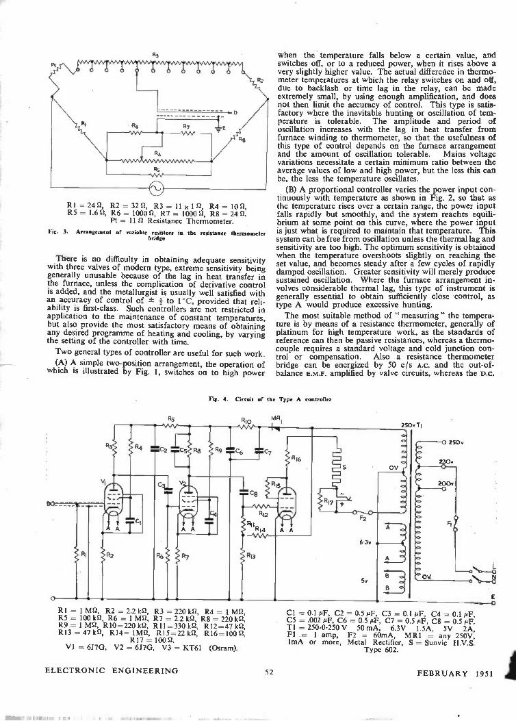
R3
RI = 24 n, R2 = 32 n, R3 =- II x 1 n, R4 = 10 n, R5 = 1.6 n, R6 = 1000 n, R7 = 1000 n, R8 = 24 n.
Pt = 11 Si Resistance Thermometer.
Fig. 3. Arrangement of variable resistors in the resistance thermometer bridge
There is no difficulty in obtaining adequate sensitivity with three valves of modern type, extreme sensitivity being generally unusable because of the lag in heat transfer in the furnace, unless the complication of derivative control is added, and the metallurgist is usually well satisfied with an accuracy of control of ±- + to 1°C, provided that reli-ability is first-class. Such controllers are not restricted in application to the maintenance of constant temperatures, but also provide the most satisfactory means of obtaining any desired programme of heating and cooling, by varying the setting of the controller with time.
Two general types of controller are useful for such work.
(A) A simple two-position arrangement, the operation of which is illustrated by Fig. 1, switches on to high power
o
R5
-
Rl
when the temperature falls below a certain value, and switches off, or to a reduced power, when it rises above a very slightly higher value. The actual difference in thermo-meter temperatures at which the relay switches on and off, due to backlash or time lag in the relay, can be made extremely small, by using enough amplification, and does not then limit the accuracy of control. This type is satis-factory where the inevitable hunting or oscillation of tem-perature is tolerable. The amplitude and period of oscillation increases with the lag in heat transfer from furnace winding to thermometer, so that the usefulness of this type of control depends on the furnace arrangement and the amount of oscillation tolerable. Mains voltage variations necessitate a certain minimum ratio between the average values of low and high power, but the less this can be, the less the temperature oscillates.
(B) A proportional controller varies the power input con-tinuously with temperature as shown in Fig. 2, so that as the temperature rises over a certain range, the power input falls rapidly but smoothly, and the system reaches equili-brium at some point on this curve, where the power input is just what is required to maintain that temperature. This system can be free from oscillation unless the thermal lag and sensitivity are too high. The optimum sensitivity is obtained when the temperature overshoots slightly on reaching the set value, and becomes steady after a few cycles of rapidly damped oscillation. Greater sensitivity will merely produce sustained oscillation. Where the furnace arrangement in-volves considerable thermal lag, this type of instrument is generally essential to obtain sufficiently close control, as type A would produce excessive hunting.
The most suitable method of " measuring" the tempera-ture is by means of a resistance thermometer, generally of platinum for high temperature work, as the standards of reference can then be passive resistances, whereas a thermo-couple requires a standard voltage and cold junction con-trol or compensation. Also a resistance thermometer bridge can be energized by 50 c/s A.C. and the out-of-balance E.M.F. amplified by valve circuits, whereas the D.C.
Fig. 4. Circuit of the Type A controller
RI = I Mn, R2 = 2.2 kn, R3 = 220 Icn, R4 = 1 Mn, R5 = 100 kn, R6 = 1 Mn, R7 -= 2.2 IA R8 = 220 kn, R9 = 1 Mn, R10=220 kn, RI 1 =330 kn, R12 .--47 kn, R13 =-- 47 kn, RI4= 1Mn, RI5=22 kn, R16=100 12,
R17 = 100 12. VI = 6J7G, V2 --= 6J7G, V3 = KT61 (Osram).
ELECTRONIC ENGINEERING 52
E
C 1 = 0.1 gF, C2 = 0.5 gF, C3 = 0.1 µF, C4 = 0.1 gF, C5 = .002 AF, C6 = 0.5 gF, Cl = 0.5 µF, C8 = 0.5 µF. TI = 250-0-250 V 50 mA, 6.3V 1.5A, 5V 2A, Fl = I amp, F2 = 60mA, MRI = any 250V, 1mA or more, Metal Rectifier, S = Sunvic H.V.S.
Type 602.
1 FEBRUARY 1951

signal from a thermocouple circuit would' have to be con-verted by a vibrator or other means to A.C. before valve amplification.
Nothing more complex than the normal Wheatstone bridge is required, but the arrangement of the variable resistances for setting the temperature is a matter of some importance. The arrangement shown in Fig. 3 takes advantage of the very high input impedance of a valve amplifier to make the current through the adjustable con-tacts almost zero. Actually it is desirable to have a resis-tance across the bridge output terminals to prevent the amplifier grid from " floating " and picking up stray signals if one of the contacts comes adrift, but it need not be less than 1 Mn if the grid lead is screened. A step-up trans-former between the bridge and the amplifier was found to be not worth while, as it would have to be specially designed to match the bridge, and thoroughly screened from the magnetic field of nearby circuits, while a considerably greater gain was obtained from an extra valve stage, with less trouble and expense. The absence of appreciable current through the contacts means that contact resistance is relatively unimportant and so enables cheap radio-type switches and potentiometers to be used satisfactorily.
The use of a multi-way switch and fixed resistors instead of a potentiometer for the coarse setting R3 is preferable as it makes the settings accurately reproducible, whereas a slight displacement on an ordinary small potentiometer as R3 would cause a considerable change in temperature. However, for heating or cooling to a desired programme, a helical potentiometer of 10 or 100 revolutions may be used for R3, and rotated by a motor. Moderate fluctuations of contact resistance cause no trouble as practically no current passes through the contact. Such a potentiometer is more expensive, however, and is not necessary for steady temperatures.
The fine control potentiometer R4 can be any easily obtainable value, e.g., 10 ohms, and is made to cover a range equal to one step of R3, with some overlap, by
using a suitable value of RS. R6 and R7 are nominally 1,000 ohms each, to limit the temperature change produced if the contact on R4 fails. On a controller to cover the range 400-1,000° C. (approximately 20-44 ohms on a thermometer of 11 ohms at room temperature), R3 con-sisted of 11 one-ohm resistors, R2 32 ohms, RI and R8 24 ohms each, RS 1.6 ohms. All resistors should be wound reasonably non-inductively, merely for the sake of avoiding magnetic pick-up in loops of wire, and screening is then unnecessary. The entire bridge circuit may conveniently be constructed on a single panel of 4 in. Tufnol sheet, on which the terminal tags are fixed and the resistance wire wound. In the event of a fault, a complete spare bridge unit may then be quickly substituted. No special trans-former is needed for the bridge supply, the 5V winding provided for a rectifier valve on a standard mains trans-former being quite satisfactory.
Electronic Circuits
In view of the need for the maximum possible reliability and life of the controllers, the designs have been varied somewhat from conventional practices. Metal rectifiers have been used in place of valve rectifiers, and paper capa-citors in place of electrolytic, any extra cost or bulk being accepted as necessary. Gas-filled valves have been avoided as they are not always as reliable over extended periods as vacuum types. The use of sharply tuned filters or trans-formers has been excluded, as such circuits might go out of adjustment or cause errors when the mains frequency varies, as it sometimes does under present conditions. Pre-set adjustments have been eliminated, so that any con-troller constructed to specification from tested components will work satisfactorily, and the only adjustment required in use is the setting of the bridge circuit to give thee desired temperature. A sensitivity control could be incorporated but has not been found necessary. Standard types of trans-formers and other components have been used, to avoid difficulty or delay in obtaining supplies.
The amplifier circuits are straightforward, but the
Fig. S. Schematic of the Type B Controller
2 A, RI = 1 M12, R2 = 1 e, R3 = 220 kn, R4 = 1.5 NV, R5 = 100 kn, R6 = 1 Mft, R7 = 220 kn, R8 = 47 kn, R9 -- 47 kn, RIO = 10 IA R11 = 6.8 e 2 W,
R12 = 47 kfl 2W 01 = 0.1 pF, C2 = 0.005 pF, C3 = 4 pF, C4 = 0.01 pF,
C5 = 0.5 pF, C6 = 0.5 pF, Cl = 4 pF. VI = SP61 (Mazda), V2 = ECC32 (Mu liard),
V3 = KT66 (Osram).
T1 = 350-0-350 V 150 mA, 6.3 V 3 A. 5 V T2 = Wharfedale G.P.8
S = Saturable Inductor, Electro Methods Type MAF 20/1150 W.
Fl = 2 amp, F2 = 250 mA, Li = 20 H. 150 mA, MR1 =-- S.T.C. V 25 40 IL.
PBBRIJARY 1951 53 ELECTRONIC ENGINEERING

response is restrici:ed somewhat at higher and lower fre-quencies than 50 c/s., to make instability easier to avoid.
To distinguish whether the bridge is above or below balance, the triode circuit, as used by Prosser and by Coates, with an A.C. anode voltage in phase with the bridge input, and the amplified bridge output applied to the grid, is simple and satisfactory. No bias voltage need be used, and a high resistance grid stopper prevents the grid from going positive, thus effectively limiting the maximum cur-rent, when grid and anode voltages are in phase. When the bridge is the other side of the balance, the grid voltage is in opposite phase to the anode, and the rectified anode current is reduced by an amount proportional to the ampli-tude of grid voltage. This circuit is much more economical and simpler in operation than the pentode circuit used by Yates, as it does not require a special transformer wind-ing, bias and screen potentiometer adjustments, double diode for limiting, or output transformer. It is used in the type A controller, Fig. 4, as the output stage, since the Sunvic Hot Wire Vacuum Switch used as the power relay responds purely to the heating or R.M.S. value of the current, and half-wave rectified current can be used. Tilt anode supply can then be obtained straight from the trans-former, and the D.C. supply of about 1 mA for the previous stages is very economically rectified, and smoothed by MR1, Cl, R10, C6, R5, C2. The value of RIS is chosen to set the maximum current through the hot wire to a safe value. If a fault in the amplifier caused no signal to appear at the grid of V3, the full relay current would be obtained and the furnace would remain switched to full power indefinitely, were it not for the signal introduced by R14 and R13, which is enough to reduce the relay current below the switching value. Apart from thus displacing the operating characteristic of the controller, this circuit does not in any way affect its operation, but it does confer added safety.,
The type A controller, including the bridge circuit, has been constructed, without any crowding or use of miniature components, on a chassis 5-1 in. by 11 in. in a metal case 74- in. high, but with the relay on the outside of the front panel. The retail price of components amounted to about £7, plus £1 10s, for a ready-made chassis and case, and £4 for the relay, totalling £12 10s.
The type B circuit has been designed to control creep testing furnaces, which run continuously for 1,000 to 10,000 hours, so that a breakdown sending the temperature high may mean the loss of months of work. The circuit, shown in Fig. 5, is generally similar to that of Coates, and uses a saturable inductor to control the furnace current. The use of a large tetrode output valve with a D.C. anode supply is in this case the most economical arrangement, giving up to 20 watts input to the saturating winding, so that the magnetic amplification required is not too great. The type MAF 20/1150 W saturable inductor has been designed by Electro Methods, Ltd., to control the 1 kW or so required (at maximum) by the furnace with a nominal 20 W (actually only 15 W is needed) which can be economically provided by the output valve. A smaller valve output would con-siderably increase the cost of a suitable saturable inductor. R11 prevents excessive screen grid dissipation at low anode voltage, but allows a higher sensitivity and less anode dis-sipation than triode connexion. The variable control grid bias for V3 is provided by the rectified and smoothed out-put of V2. A small 12:1 loudspeaker transformer steps up the heater voltage to give about 75 volts tic. on the anode of V2, which is quite adequate for full control of V3.
Loss of cathode emission in V2 would remove the bias from V3 and allow maximum furnace current to flow, so a double triode of ample cathode and anode ratings, with parallel-connected heaters, has been used with the two sec-tions in parallel, to give a greater factor of safety. Possibly this could be improved upon by using a metal rectifier to
provide a fixed negative bias for 113 and arranging V2 to give a positive output, but it would involve additional com-plication of the circuit. Loss of emission in VI or V3, or loss of signal before V2, will cause a drop in temperature. It is not practicable to arrange for every possible fault to send the temperature down, but this can be done for the most usual types of fault, such as broken heater, loss of emission, or loss of signal amplification through short or open circuits. Analysis of valve failures in the 18,800-valve ENIAC,'' during a year of operation, has shown that these are the most frequent faults. All the valves are run well below their maximum dissipation limits, and the H.T. supply, rated at 150 mA, normally supplies only 70 to 80 mA, with 100 to 120 mA during initial heating up of the furnace. The use of metal rectifiers and a choke input filter should ensure the maximum life, and if one rectifier fails to pass current the other should be able to maintain the H.T. supply.
The retail price of components for the type B instrument, including everything but the saturable inductor, is about £13.
The correct operation of both types of controller may be checked by plugging a milliammeter into the anode cir-cuit of the output valve, and connecting a fixed resistance of, say, 30 ohms as thermometer. The change in output current, produced by a resistance of about 10,000 ohms placed across the thermometer, can then be used as a measure of the sensitivity and will show whether the bridge input needs reversing to give the correct sense of operation. The bridge controls should, of course, be set to bring the output current to a suitable point on the operating charac-teristic, about half maximum. If a meter jack is built permanently into the instrument, the contacts which are opened by pushing the plug in may give trouble, so it is desirable to put a 100 ohm resistance across them, or to use a voltmeter, across the anode load, instead of a milli-ammeter, to prevent failure of the controller if the contacts become dirty.
The use of a saturable inductor to give continuous varia-tion of furnace current has many advantages. It eliminates the switching relay, a probable source of trouble after long periods of use, and should be as reliable as a transformer. It gives more sensitive control without hunting than a system in which proportioning is done by varying the ratio of on and off periods, since it gives immediate correction for any change in conditions and produces no periodic cycling of heat input. The repeated violent fluctuations of heat input to the furnace and power taken from the supply mains are also eliminated, full power being used only during initial heating up. It is unnecessary to use any variable voltage tappings or rheostats for temperatures in the range 400 to 1,000° C. used for most creep testing. Excellent control has been obtained on furnaces run from a supply subject to large variations of voltage, caused by arc furnaces on the same line, where other controllers of the switching proportioning type have given inferior results.
Both types of controller described have been used for some time in these laboratories by people not conversant with electronic circuits and have given very little trouble over long periods.
Acknowledgment
The author's thanks are due to the Electronics and Creep Laboratories assistants who have helped in constructing the instruments described, and to Dr. C. Sykes, Director of the Brown Firth Research Laboratories for permission to publish this paper.
REFERENCES
' Prosser, Engineering, 148, 95, 1939.
Coates, G. E., Journal Scientific Instruments, 21, 86. 1944.
' Yates, E. L., Journal Scientific Instruments, 23, 229, 1946.
' Michael, F. R., Electronics, 20, 117, 1947.
ELECTRONIC ENGINEERING 54 FEBRUARY 1951

A Precision Electronic Tachometer By S. W. Punnett, B.Sc.* and H. G. Jerrard, B.Sc., A.Inst.P.*
THE measurement of speeds of revolution of roiating shafts can be carried out in several ways, the method
employed depending on the conditions which exist and the accuracy desired. Accurate methods most recently developed appear to be those in which the number of revolutions occurring in an accurately measured interval of time is electronically counted.' Whatever the method, however, a tachometer may with advantage possess the
Fig. 1. Circuit of A.F. Amplifier RI = 2 MCI, R2 = 20 kn, R3 = 100 R4 = I Mt, R5 = 300 e. R6 = 20 kn, R7 = 100 kn, R8 = 2 mn, R9 = 0.5 ma, RIO = 1 ka, R11 = 300 kn. CI = 4 pF. C 2 = 0.5 pF, C3 = 001 ¿IF, C4 = 4 eiF, C5 = 0.01 /IF, C6 = 25 µF, Cl = 0.5µF. VI = V2 = 6SJ7.
SELECTIVE AMPLIFIER
—0 INPUT FROM GENERATOR
following features: it should (1) require little or no alteration to the. shah, (2) impose no load on the shaft, (3) give direct and continuous reading, (4) be capable of the immediate detection and measurement of shwa varia-tions in speed, (5) have the spud indicator remote from
Unirerslts College, Southampton.
250v
Y- PL ATES
the shaft, (6) give no ambiguity and be easy to use, (7) be small and light, (8) give high accuracy over a wide range.
In this article a description is given of the circuit details of an electronic tachometer accurate to 0.05 per cent which satisfies these requirements and whose upper speed limit can be made far in excess of that likely to be required in practical use.
In the instrument to be described an alternating voltage is generated by the rotating shaft and is fed through an A.F. amplifier to the Y-plates of a cathode-ray tube. The output of a variable frequency oscillator is connected to the X-plates. The resultant trace on the tube is a Lissajous figure. If the frequency of the oscillator be adjusted so that the figure is easily identifiable and if the oscillator frequency be known, then the unknown frequency is immediately found. Any slight variation of speed causes a precession of the Lissajous figure and the change is easily recognizable. Larger changes alter the figure com-pletely and thus there can be no ambiguity.
Description of Components
(a) THE ALTERNATING VOLTAGE G ENEILATOR.—To generate by the movement of the shaft the required alternating voltage two types of generator unit are employed.' The first type is electro-magnetic, in which an alternating voltage is induced in a small pick-up coil placed near the shaft by changing the magnetic flux linked with the coil. The unit is very similar to those employed in tachometers which use an A.C. meter to measure the voltage so produced, and hence give an indication of the o speed of the shaft. The second type employs a photo-electric cell which, when placed near the shaft, can receive light intermittently reflected from the shaft. To obtain this reflected light a narrow strip of paper of length equal to the circumference of the shaft and ruled with alternate black and white bands of equal width is attached to the shaft. The paper strip has a matt surface, and in addition the light falling on it is diffuse, so that there is no focus-
Fig. 2. Circuit Diagram of Signal Generator RI = 4.7 MI?, R2 = 470 R3 = 100 Ica R4 = 22 kn, R5 = 22 ka R6 = 22 kn, R7 = 22 k , R8 = 150 R9 = 22 ka, RIO = 30 kn, R11 = 30e, RI2 = 22 kn, R13 = 22 kn, R14 = 50 kn, R1.5 = 150 n, R16 = 50 ka R17 = 30 e, R18 = 30 kn. R19 = 100 Ica R20 = 22 02, R2I = 22 ka, R22 = 100 ka R23 = 3oo kn. R24=200 kn, R25 = 150 a, R26 = 100 e, R27 =100 kn, R28=33 kn, R29 = 1 kn, R30 = so kn, R31 = 100 kn.
CI = 12 pF, C2 -= 0.1 pF, C5 = 12 pF, C6 = 0.001 pF, C9 = 12 pF, C10=0.005 /IF. C13=12 pF, C14=0.05 uF, C C17=0.01 pF, C18 = 0.1 pF. V1 = V5 = SP61, V2 = V3 X = 100 kc/s. crystal. L
C3 = 0.1 pF, C4 = 12 pF, C7 = 0.001 pF, C8 = 12 pF, C11=0.005 pF, C12=12 pF, • 15=0.05 pF, C16-0.00I pF,
= V4 = 6SN7. = 15 mH.
•i 0 250v
Ft3I
SELECTIVE
AMPLIFIER
IF°
ER28
0 0
55 I EBRUARY 1951 ELECTRONIC ENGINEERING
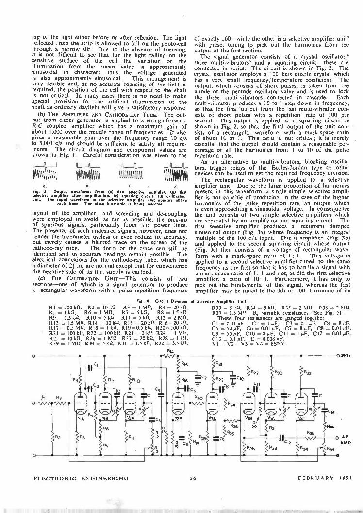
ing of the light either before or after reflexion. The light reflected from the strip is allowed to fall on the photo-cell through a narrow slit. Due to the absence of focusing, it is not difficult to see that for the light falling on the sensitive surface of the cell the variation of the illumination from the mean value is approximately sinusoidal in character: thus the voltage generated is also approximately sinusoidal. This arrangement is very flexible and, as no accurate focusing of the light is required, the position of the cell with respect to the shaft is not critical. In many cases there is no need to make special provision for the artificial illumination of the shaft as ordinary daylight will give a satisfactory response.
(b) THE AMPLIFIER AND CATHODE-RAY TUBE.—The out-put from either generator is applied to a straightforward R-C coupled amplifier which has a maximum gain of about 1,000 over the middle range of frequencies. It also gives a reasonable gain over the frequency range 10 c/s to 5,000 c/s and should be sufficient to satisfy all require-ments. The circuit diagram and component values are shown in Fig. I. Careful consideration was given to the
111M IPM, 0. b. C. d.
Fig. 3. Output waveforms from (t) first selective amplifier. 0)1 first selective amplifier after amplification, (c) squaring circuit. (d) calibration unit. The input waveform to the selective amplifier unit appears abole
each trace. The sixth harmonic is being selected
layout of the amplifier, and screening and de-coupling were employed to avoid, as far as possible, the pick-up of spurious signals, particularly from A.C. power lines. The presence of such undesired signals, however, does not render the tachometer useless or even reduce its accuracy, but merely causes a blurred trace on the screen of the cathode-ray tube. The form of the trace can still be identified and so accurate readings remain possible. The electrical connexions for the cathode-ray tube, which has a diameter of 2+ in. are normal except that for convenience the negative side of its H.T. supply is earthed.
(C) THE CALIBRATION UNIT.—This consists of two sections—one of which is a signal generator to produce a rectangular waveform with a pulse repetition frequency
Fig. 4. Circuit Diagram
RI = 200 kn, R2 = 10 IA R3 = I mre, R4 = 20 R5 = 1 kn, R6 = 1 MS-2, R7 = 5 kn, R8 = R9 = 3.5 ka, RIO = 5 IcS2, R11 = 5 ksi, R12 = 2 Mn, R13 = 1.5 Ma. R14 = 10 kit, R15 = 20 e, R16=20 e, R17 = 0.5 M12, R18 = 1 kn. R19=0.5 ka, R20=100 IA R21 = 100 e, R22 = 100 kn, R23 = 2 la R24 = 1 Mn, R25 = 10 0. R26 = 1 Mg R27 = 20 kn. R28 = 1 kn. R29 = 1 Mn, R30 = 5 ka, R31 1.5 ka, R32 = 3.5 ka,
R 3 '
VIA
R2
Fltg
of exactly 100—while the other is a selective amplifier unit' with preset tuning to pick out the harmonics from the output of the first section. The signal generator consists of a crystal oscillator,'
three multi-vibrators' and a squaring circuit: these are connected in series. The circuit is shown in Fig. 2. The crystal oscillator employs a 100 kc/s quartz crystal which has a very small frequency/temperature coefficient. The output, which consists of short pulses, is taken from the anode of the pentode oscillator valve and is used to lock the three multi-vibrators connected in cascade. Each multi-vibrator produces a 10 to 1 step down in frequency, so that the final output from the last multi-vibrator con-sists of short pulses with a repetition rate of 100 per second. This output is applied to a squaring circuit as shown in Fig. 2, so that the final output of the unit con-sists of a rectangular waveform with a mark-space ratio of about 10 to 1. This ratio is not critical; it is merely essential that the output should contain a reasonable per-centage of all the harmonics from 1 to 10 of the pulse repetition rate. As an alternative to multi-vibrators, blocking oscilla-
tors, trigger relays of the Eccles-Jordan type or other devices can be used to get the required frequency division. The rectangular waveform is applied to a selective
amplifier unit. Due to the large proportion of harmonics present in this waveform, a single simple selective ampli-fier is not capable of producing, in the case of the higher harmonics of the pulse repetition rate, an output which is even approaching a sinusoidal voltage. In consequence the unit consists of two simple selective amplifiers which are separated by an amplifying and squaring circuit. The first selective amplifier produces a recurrent damped sinusoidal output (Fig. 3a) whose frequency is an integral multiple of the 100 c/s input. This is amplified (Fig. 3b) and applied to the second squaring circuit whose output (Fig. 3c) then consists of a voltage of rectangular wave-form with a mark-space ratio of 1: 1. This voltage is applied to a second selective amplifier tuned to the same frequency as the first so that it has to handle a signal with a mark-space ratio of 1: 1 and not, as did the first selective amplifier, a ratio of 10: 1. Furthermore, it has only to pick out the fundamental of this signal, whereas the first amplifier may be tuned to the 9th or 10th harmonic of its
of Selective Amplifier Unit
R33 = 5 kn, R34 = 5 ka, R35 = 2 mn, R36 -= 2 MS2, R37 = 1.5 Mn. R, variable resistances. (See Fig. 5). These four resistances are ganged together.
Cl = 0.01 pF, C2 = 1 pF, C3 = 0.1 »I'', C4 = 8 pF, C5 = 50 pF, C6 = 0.01 pF, C7 = 8 pF, C8 = 0.01 pF, C9 = 50 pF, CIO = 8 pF, CI I = 1 pF, C12 = 0.01 pF, C13 = 0.1 µF. C = 0.008 pF. VI = V2 =V3 = V4 = 6SN7.
AF AMP
•
ELECTRONIC ENGINEERING 56 FEBRUARY 1951

input signal. Thus the second selective amplifier, which •has a moderate Q-factor, produces an almost sinusoidal output (Fig. 3d). The circuit and component values are shown in Fig. 4.
The two selective amplifiers are identical in form; each consists of a single valve amplifier whose output is applied to two phase shifting circuits connected in cascade. A fraction 1/n of the output of the second phase shifting circuit is applied to the input grid of the valve amplifier.
o
Fig. 5. Switch Arrangement of Selective Network
C = 0.008 ,uF RI = 20 kn, R2 = 2.22 kn, R3 = 2.78 kn, R4 = 3.6 kg R5 = 4.7 kn, R6 = 6.67 ka. R7 - 10 kn, R8 = 16.7 kn, R9 = 33.33 kn, R10 = 100 kn.
o
Fig. 6. Circuit Diagram of Variable-Frequency Oscillator
RI = 30 kn, R2 = 1.2 kn, R3 = 0.5 Mn, R4 = 43 k12, R5 = 1.8 et, R6 = 15 IA R7 =1 kn, R8 = 10 krz, R9 = 2 Mn, R10 = 43 kn, R11 = 10 kn, R12 = 2.2 kn. R13 = 1.2 kn, R14 = 2 MU, R15 = 150 kn. RI6= 10 kn. R17=10 kn. RI8 =0.22 Mn, R19=0.66 Mn, R20=2 M12, R21=6 M22. R22=0.22 Mn, R23=0.66 Mn, R24=2 Mn,
150v o
C
X -PL ATES 0-11
00
2`7
R14
v P26 n",7 c11
it can be shown that the feedback is given by the expression
1 2 - jy - - • n 2 + jy
f fo 1 where y = - - and fo = fo f 27rCR
This expression is deduced ignoring such effects as stray capacitances, load impedance, etc. The frequency f is that of the applied signal; C and R are the values of the components of the networks connecting anode and cathode of the two phase inverting valves. (See Fig. 4.)
If now the gain of the amplifier valve without feedback is A, then the gain, G, with feedback is given by,
A(2 + jy) G _
2(1 - Aln) + jy(1 + Aln)
G.(1 + jy/ 2)
- 1 + jG. (1 / 2A + 1/2n) y where G. is the gain when the applied frequency f is equal to fo. When A is small and n is made very slightly smaller than A so that G. is large the following approximate expression is obtained for the gain G.
G - G0(1 +.iY12) 1 + jy (Gol A)
so that the effective Q factor of the complete circuit near resonance is approximately Gol A. At the frequency f. the two phase shifting circuits each
produce a phase shift of ir/ 2, giving a total phase change of ir so that positive feedback results and therefore the gain of the amplifier is large. At all other frequencies the feedback is not in phase with the input and this gives a reduced gain. A frequency at which the feedback is positive must always exist with this circuit; tuning is thus very simple. The capacitors, C, employed need not be accurately adjusted. The form of the phase shifting resistors together with their switch arrangement is shown in Fig. 5. To adjust the selective amplifier to the desired frequencies it is only necessary to make small changes in one of the two chains of resistors. In actual practice the phase shift in each phase shifting circuit need not be exactly i/2; it is only necessary that the sum of the two phase shifts shall be 7.
This selective amplifier circuit theoretically has one
R25=6 Nin, R26=3.3 kn, R27=500 a Cl = 0.05 µF, C2 = 0.05 pF, C3 = 0.5 PF, C4 = 0.1 pF, C5 = 0.5 pF, C6 = 50 PF, C7 = 8 pF, C8 = 0.5 pF, C9 = 0.1 pF, C10 = 8 pF, C11 = 50 pF, C12 = 600 pF. C13 = 20 pF, C14=1000 pF, C15=100 pF, C16=500 pF.
C17 = 20 pF, C18 -= 1000 pF. VI = 6J5G, V2 = V3 = V4 = 6S17. V5 = 120 V, 3 W lamp.
C 12 IRK)
Re
2 R21
57 FEBRUARY 1951 ELECTRONIC ENGINEEFUNG

GENERATOR 0 0O
SELECTIVE AMPLIFIER
A. F
AMPLIFIER
CATHODE RAY
TUBE
VARIABLE
FREQUENCY
OSCILLATOR
STANDARD
FREQUENCY
GENERATOR
Fig. 7. Arrangement of Tachometer Componen:s
other advantage in that if the effects of stray capacitances, load impedance, etc., are again ignored, the magnitude of the voltage fed back to the input is independent of the sizes of C and R and of the frequency. The resultant sinusoidal output of the whole selective
amplifier unit whose frequency can be that of any har-monic of the 100 c/s multivibrator is applied to the cathode ray tube after amplification by the main A.F. amplifier (see Fig. 7); this is necessary to produce a reasonable deflexion on the tube. Although in the circuit shown the tenth harmonic is the highest available, it is possible by using Lissajous figures of different orders to standardize a very large number of points on the dial of the variable frequency oscillator. The preset tuning of this tuned selective amplifier unit« is accomplished by the use of a four-gang switch which connects the required resistors into the phase shifting networks.
(d) THE VARIABLE FREQUENCY OSCILLATOR. To obtain an accuracy as high as 0.05 per cent it is essential to use a variable frequency oscillator possessing good frequency stability. It is not necessary this should be long term stability since the frequency can be quickly re-checked by the unit described in section (c). The circuit is as shown in Fig. 6. The principle is the same as that employed in ordinary
R —C coupled oscillators but erecautions are taken to secure short term stability as far as possible of the fre-quency of the output. Further it is necessary to open out the scale so that the dial can be read to the desired accuracy. To secure this open scale the frequency covered by each switch position is decreased from the more usual 10 to 1 employed in this type of oscillator to 3 to 1. Capari-tance tuning is employed and thus large fixed shunt capacitances are connected across each section of the ganged tuning capacitances so that the ratio of maximum to minimum is 3 to 1. High stability resistors are employed for the resistors R18 to R25 (Fig. 6) of the frequency determining network. The large values required for these rendered impracticable the use of wire wound types so that
Fig. 8. Typical traces for electro-magnetic generator. First, second and third order Lissajous figures representing speeds of 600. 1.200 and
1,800 r.p.m.
high-stability cracked carbon resistors have been employed. These have a negative temperature coefficient of the order of 200 parts per million per °C and, in conjunction with a suitable selection of capacitors for the fixed shunt across the tuning capacitors, partial compensation for tempera-
Fig. 9. General view of tachometer and photo-electric generator
turc changes has been achieved. Complete compensation with this arrangement is not practicable as capacitors with temperature coefficients greater than plus 140 parts per million per °C are not commercially available. However, after an initial warming up period of abouf twenty minutes the oscillator gave a highly satisfactory performance at room temperature.
It is possible to obtain an even greater temperature stability by using a frequency determining network in which the capacitances have fixed values and the tuning is accomplished by the use of variable resistors. The in-creased cost usually does not warrant this especially as the effect of slow changes in temperature is removed by periodic calibration. The effects of mains voltage variation are eliminated
by using a valve stabilizer of standard pattern.' The frequency dial is supplied with a vernier reading
to five parts in ten thousand and small ganged trimming capacitors are provided so that the dial may be reset if necessary each time the oscillator is calibrated. The arrangement of the complete circuit is shown in
Fig. 7. Initially the outptes of the variable frequency oscillator and the calibration units are connected to the X and Y plates of the cathode ray tube respectively. By using suitable stationary Lissajous figures the former is calibrated. The calibration unit is switched off, whereupon the tachometer is ready for use with either generator. Fig. 8 shows typical traces.
Conclusion and Acknowledgment The tachometer described above is suitable for any speed
range and possesses the features outlined above in the introduction. The complete unit shown in Fig. 9 occupies
a space of only 18 in. by 14 in. by 12 in. and weighs less than 80 lb. If miniaturization technique is employed these figures can be considerably reduced. By the use of a shielded cable from the indicator to the generator head the former can be at any distance from the shaft. The authors wish to express their thanks to Messrs.
R. D. Hilton and G. Q. McColl, who constructed the apparatus, and to Professors A. M. Taylor and E. E. Z,epler in whose laboratories this work was carried out.
REFERENCES ' Finden, H. J. : Electronic Engineering, 22, 2 1950. Jerrard, H. G. and Punnett, S. W. : J. Sri. Instrum (27, 244, 1950). " Vacuum Tube Amplifiers." Radiation Laboratory Series, 1st ed., 18, Chain. 10. New York : McGraw-Hill Book Co., 1948. " Waveforms." Radiation Laboratory Series, tat ed., 19, p. 16. New York : McGraw-Hill Book Co., 1948. •" Waveforms," Radiation Laboratory Series, 1st ed., 19, Chapt. 16. New York : McGraw-Hill Book Co., 1948. Terman, F. E. : " Radio Engineers' Handbook," 1st ed., p. 614. New York : McGraw-Hill Book Co., 1943.
ELECTRONIC ENGINEERING 58 FEBRUARY 1951

Inverse or Reciprocal Scales from Linear Potentiometers A. F. Boff, B.Sc. *
I N the design of measuring equipment it is often required to divide a potential in accordance with an inverse or
reciprocal law. Frequently, wire-wound potentiometers are used in which the core is tapered, or the wire graded, in an endeavour to attain the characteristic required but, owing to the inherent practical difficulties of constructing an element having a truly reciprocal law, the result is very approximate and usually inadequate. In this article a simple method is described by means of which exact reciprocal scales and approximate logarithmic scales, may be obtained using standard linear components.
i• o
60
120
180 1 0 60 120 180 240 300
00
Fig. I. Characteristics of normal linear potentiometer and logarithmic potentiometer
Fig. 2. Effect of shunting a linear potentiometer with a fixed resistor
1.0
08
o.
02
L
0 60 120 180 240 300
130
o
60
120
180
e 240
Fig. 1 shows the characteristic obtained by normal use of a linear potentiometer, and for comparison, the curve of a logarithmic potentiometer of well-known manufacture.
It has been assumed that the total angular rotation of the potentiometer scale is 3000; a figure in accordance with most types commercially available.
Figs. 2 and 3 illustrate the effect of shunting a linear potentiometer by a fixed resistance connected to the moving contact. Values of the ratio R 1 /R2 are indicated on the curves.
In practice the entire range of the curves is rarely required and the useful working range is therefore res-tricted to perhaps two thirds or less of the available rotation of the potentiometer. A considerable improve-ment is indicated in Figs. 4 and 5 in which one end of the potentiometer is open-circuited. The method is rendered still more universal by the insertion of a resistance in series with the potentiometer as shown in Figs. 6 and 7, and its effect is illustrated in the accompanying curves.
Design of Such a potential divider is influenced by the
Formerly of Standard Telecommunication Laboratories, Ltd.
o 60 120 180 240 300
e°
value of potentiometer RI, which is not readily obtainable in wire wound types for values in excess of 100,000 ohms and also by the permissible current from the source of potential. An example will serve to illustrate application of the
device :— A source of potential of 12 volts is available and a
potential divider is required having a range of 10 volts to 1 volt, according to a reciprocal law (Fig. 8). Calculation by the method given below gives the following ratio: —
R1 /R2 = 10.8 and R3/R2 = 0.2
0 60 120 180 240 300
e
Er Fig. 3. Effect of alternative method of shunting a linear potentiometer
with a fixed resistor
Fig. 4. ‘s for Fig. 2. Init with one end of the notentiometer disconnected
o
60
120
180
240
300
e°
In order to keep the t urrent as small as possible R2 and hence RI should be as large as possible.
Let RI = 100,000 ohms, then R2 = 100'000 10.8 — 9260 ohms also R3 = 0.2 x R2 = 1850 ohms
The circuit of Fig. 9 will therefore provide the desired characteristic, and the maximum current taken from the source is:
El (R2 + R3) = 1.08 mA Calculation. The general mathematical expressions for
the curves of Figs. 6 and 7 respectively are,
e (I) E A + K019° e 1 E IA+K(1— 010°
where E = Potential to be divided
e -= required portion of potential
(2)
FEBRUARY 1951 59 ELECTRONIC ENGINEERING

••• 60 120 180 240 300
0°
9" = range of angular rotation of potentiometer
= angular rotation of potentiometer from posi-tion of maximum potential
A = constant
K = constant
Consider the circuit of Fig. 6 where R2, R3 are fixed resistors and RI is a linear potentiometer, then:—
R2 R3
- R2 + R3 + RI 010° (' Ri
Comparing this equation with equation
A = 1 + R3/R2 .... (3) K = RI/R2 (4)
thus by suitable choice of values fc • Ri, R2, R3, any desired values of A and K may be ob:ained.
Similarly for the circuit of Fig. 7.
R3 + RI (1 - 010°)
= R2 +R3 + R1 (1 - 010°)
1 = I -
(1 + R3/R2) RI/R2(1 -
) ILR2 9164°
(1) we see that,
o
60
120
180
240
300
e°
Fig. 5. As for Fig. 3. but with one end of the notentioine:er disconnected
Fig. 6. Circuit of Fig. 4 with series resis:or added to potentiometer
0
0 60 120 180 240 300
60
120
180
240
300
Hence by comparison with equation (2)
A = 1 + R3/R2
K = RI/R2 as before
In the example used for illustration above we have the following data:
E = 12V
when 9 = 0, e is required to be 10 V
when 0 =- 00, e is required to be 1 V
Now using Equation (1) and substituting E = 12, •
= 10 and E = 12. 9 = 0°, e= l 'we have 10/12 = 1/A Hence A = 1.2
and 1/12 = I/A + K .*. A + K = 12
but A = 1.2 .*. K = 10.8
Hence from equations (3) and (4) we have
R3 = 0.2 R2
RI = 10.8 R2
which are the ratios used in the example.
R2
E
60
120
180
240
_ _300
60 120 1CO 240 300 90
e°
Fig. 7. Circuit of Fig. 5 with series resistor added to potentiometer
Fig. 8. Characteristic required in Fig. 9. Required saurs to g've numerical examp:e the characteristic of Fig. fl
o 0 60 120 180 240 300
eo
High-Speed Waveform Monitor
A.E.R.E., Harwell, have developed a high-speed oscillo-scope tor testing scalers, amplifiers, coinciaence circuits, etc. Y voltage measurements can be made by balancing in
a bridge circuit the input signal potential against a D.C. potential supplied by the oscilloscope circuit, and metered by a built-in high grade multi-range moving coil voltmeter. Measurements can be made on A.C. and D.C. signals, and as it is a null method the accuracy is independent of Y ampli-fier linearity and gain, and of mains input variations. The Y amplifier enables a sensitivity varying from 2 mm
volt to 2.3 cm volt to be achieved with a rise time of 0.07jA seconds. For inspection of hum levels, etc., a sensi-tivity of un to 15 cm/volt is available with some deteriora-tion of transient response.
Time base speed is variable by means of a switch as .follows: 1.5, 5, 15, 50, 150 and 500 micro-seconds, and 1.5, 5, 15 and 50 milliseconds. In addition, by operation of the X gain control the effective length of the trace can be expanded from about 8 to 50 cm, any portion of which can be viewed by operation of the X shift control. Recovery time varies with sweep speed; it is about
ALLS on the 1.54 setting and 33 mS on the 55 rnS settings. Normally the fly-back is blacked out and a jack is pro-
vided to inject external blackout waveforms. The monitor is manufactured by E.M.I., Ltd., Hayes,
Middlesex, and is known as the High Speed Waveform Generator, Type 3794B.
ELEC-FRONIC U: .i1NEERING 60 FEBRUAR1 •()51

The Effect of Pen-to-Paper Friction in
Recording Instruments By M. J. Tucker, B.Sc. *
THE effect of friction between the pen and chart of I recording ammeters and other devices using mechanical registration can be of importance in accurate work. For example, in the recording ammeter used for most of the investigations described in this article (an " Evershed and Vignoles" 500 ohm 3-0-3 milliamp recorder using the Murday system), the maximum deflexion supportable by static friction alone could be over 3 per cent of the scale-width, and a similar figure was obtained when the pen-to-paper friction in an Esterline-Angus 1 milliamp 1,300 ohm recorder was measured. In practice the effect is usually reduced by the movement of the chart, and in many industrial applications where recording meters are used to measure slowly varying quantities that do not produce steep curves, the effect is negligible. However, appreciable errors can be introduced when steep curves are recorded. The main difficulty in dealing with static friction is its
unreliable nature. Measurements of the friction between the same pen and chart roll in a recorder using the Murday System varied from the mean by as much as 60 per cent, though this was mostly due to the pen being tilted at extreme deflexion, in which circumstances the friction also varied according to the direction of measurement. How-ever, even in the centre of the chart successive measure-ments varied from the mean by up to 20 per cent, the friction being practically independent of the direction of measurement here. This means that calculations of the effect of static friction are approximate and must be used with caution.
Experiment indicates that the stationary and moving friction of the pens is the same, and this will be assumed in this article. It will also be assumed that the friction is the same for all directions of movement of the pen. The weight of ink in the pen is important and in pens
of the reservoir type where this can vary, corrections must be based on a friction value corresponding to the correct weight of ink. A Murday reservoir pen when full of ink has approximately twice the friction of an empty pen. The effect of static friction may be practically eliminated
if there is a comparatively high frequency vibration super-imposed on the pen, and it is a well-known practice to superimpose a small amount of 50 c/s current on the input to electrical recorders for this purpose. The A.C.
power required is very small, being that which will cause a just noticeable thickening of the record line. Where a vibration is fortuitously present it can invalidate static friction corrections. With seismographs it has been found that vibration from sources such as lorries passing on nearby roads can reduce friction effect to negligible pro-portions.
This article assumes that the recording is taking place sufficiently slowly for the effects of inertia and of fluid or magnetic damping to be neglected, and that the pen moves perpendicularly to the direction of movement of the paper. The errors invo'ved in applying the results to curved-scale recorders will not be large.
Measurement of the Static Friction
A convenient practical measure of the amount of static -----------• National hisiitute of 0.-eanograPhY•
friction is the maximum deflexion supportable by static friction alone, and this, measured as a distance, is used below as the static friction constant K. It may be measured directly by letting the pen return slowly from a small deflexion and measuring the final distance from the true zero. The chart must, of course, be stationary during the return, but should be moved forward just before this starts, so that the pen moves over clean paper. When using electrical recorders, the deflecting force is best pro-duced by a small current and the slow return by thick oil in the dash-pot. The average of several readings should be taken. The pen will sometimes catch on a paper fibre. and cases should be disregarded where this has obviously happened. The value of K can also be obtained from the shape
of the error decay curve drawn by the pen when the paper is moving. Fundamentally this method is better as it measures the moving friction and takes an average over a length of line. However, the two methods are found to give similar results and the direct method described above is much less laborious.
Fig. 1. Diagram of the forces exerted on the pen by its supports
yt O
DIRECTION OF
CHART MOVEMENT X
Fy —y5 Fc (CONSTANT
MAGNITUDE)
Basic Equation for Calculating the Error at any Point
Fig. 1 is a diagram of the forces exerted on the pen by its supports. y is the error deflexion due to static friction, and hence
the force Fs tending to return the pen to the true position is —yS. where S is the restoring force per unit deflexion of the pen. F. is the force along the direction of movement of the
chart. F. is the force of constant magnitude necessary to over-
come static friction, and is thus the resultant force on the pen when it is moving over the paper. This force will act along the tangent to the curve at the point of writing. so that O is the angle lyeween the tangent to the curve and the x axis.
Since F = —yS, the error deflexion y is given by y —F,/S F,. sin 01.5
K (the maximum deflexion supportable by friction alone) is given by y, so that when O = 90*
K -= F..IS and y = K sin (11
FEBRUARY 1951 61 ELECTRONIC ENGINEERING
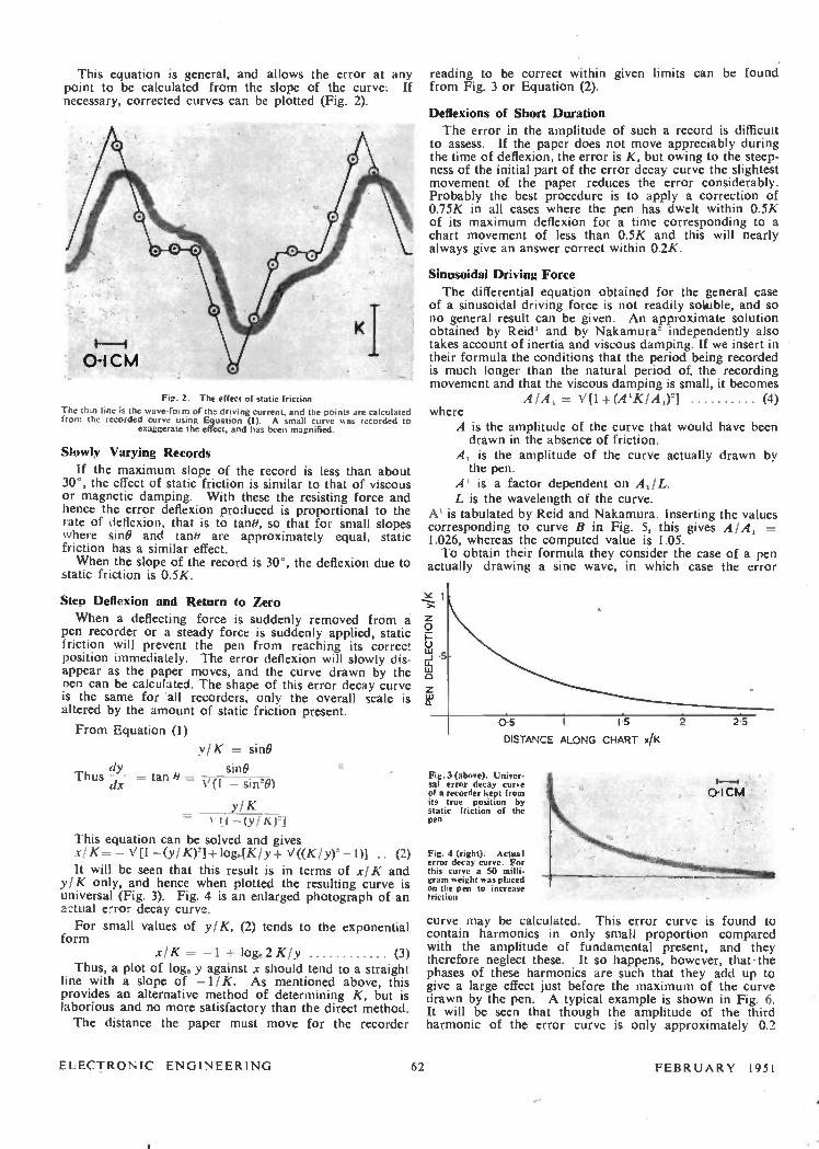
This equation is general, and allows the error at any point to be calculated from the slope of the curve. If necessary, corrected curves can be plotted (Fig. 2).
Fig. 2. The effect of static friction
The thin line os the wave-foi m of the driving current, and the points .ire calculated from the recorded curve using Equation (I). A small curve sas recorded to
exaggerate the effect, and has been magnified.
Slowly Varying Records
If the maximum slope of the record is less than about 30°, the effect of static friction is similar to that of viscous or magnetic damping. With these the resisting force and hence the error deflexion produced is proportional to the rate of deflexion, that is to tane, so that for small slopes where sine and tane are approximately equal, static friction has a similar effect. When the slope of the record is 30°, the deflexion due to
static friction is 0.5K.
Step Deflexion and Return to Zero
When a deflecting force is suddenly removed from a pen recorder or a steady force is suddenly applied, static friction will prevent the pen from reaching its correct position immediately. The error deflexion will slowly dis-appear as the paper moves, and the curve drawn by the Den can be calculated. The shape of this error decay curve is the same for all recorders, only the overall scale is altered by the amount of static friction present.
From Equation (1)
Thus dy dx
yIK = sine
sine -=- tan 40 = V(I sin20)
yIK = — (y116, ).1
This equation can be solved and gives x/K-- — V[I —(y1K)2] log,.[K I y + V ((K I y) — I)] (2)
It will be seen that this result is in terms of xIK and yIK only, and hence when plotted the resulting curve is universal (Fig. 3). Fig. 4 is an enlarged photograph of an actual error decay curve.
For small values of yIK, (2) tends to the exponential form
xIK =- —1 + log. 2K/y (3) Thus, a plot of loge y against x should tend to a straight
line with a slope of —1/K. As mentioned above, this provides an alternative method of determining K, but is laborious and no more satisfactory than the direct method. The distance the paper must move for the recorder
reading to be correct within given limits can be found from Fig. 3 or Equation (2).
Deflexions of Short Duration
The error in the amplitude of such a record is difficult to assess. If the paper does not move appreciably during the time of deflexion, the error is K, but owing to the steep-ness of the initial part of the error decay curve the slightest movement of the paper reduces the error considerably. Probably the best procedure is to apply a correction of 0.75K in all cases where the pen has dwelt within 0.5K of its maximum deflexion for a time corresponding to a chart movement of less than 0.5K and this will nearly always give an answer correct within 0.2K.
Sinusoidal Driving Force
The differential equation obtained for the general case of a sinusoidal driving force is not readily soluble, and so no general result can be given. An approximate solution obtained by Reid' and by Nakamura' independently also takes account of inertia and viscous damping. If we insert in their formula the conditions that the period being recorded is much longer than the natural period of the recording movement and that the viscous damping is small, it becomes
AIA, = V[1-f-(A`KIA,)2] (4) where
A is the amplitude of the curve that would have been drawn in the absence of friction.
A, is the amplitude of the curve actually drawn by the pen.
A' is a factor dependent on A,/L. L is the wavelength of the curve.
A' is tabulated by Reid and Nakamura. Inserting the values corresponding to curve B in Fig. 5, this gives 21/441 = 1.026, whereas the computed value is 1.05. To obtain their formula they consider the case of a pen
actually drawing a sine wave, in which case the error
65 j 5
DISTANCE ALONG CHART x/K
Fig. 3 (above). Univer-sal error decay curve of a recorder kept from its true position by static friction of the pen
Fig. 4 (right). Actual error decay curve. For this curve a 50 milli-gram weight was placed on the pen to increase friction
25
curve may be calculated. This error curve is found to contain harmonics in only small proportion compared with the amplitude of fundamental present, and they therefore neglect these. It so happens, however, that-the phases of these harmonics are such that they add up to give a large effect just before the maximum of the curve drawn by the pen. A typical example is shown in Fig. 6. It will be seen that though the amplitude of the third harmonic of the error curve is only approximately 0.2
ELECTRONIC ENGINEERING 62 FEBRUARY 1951
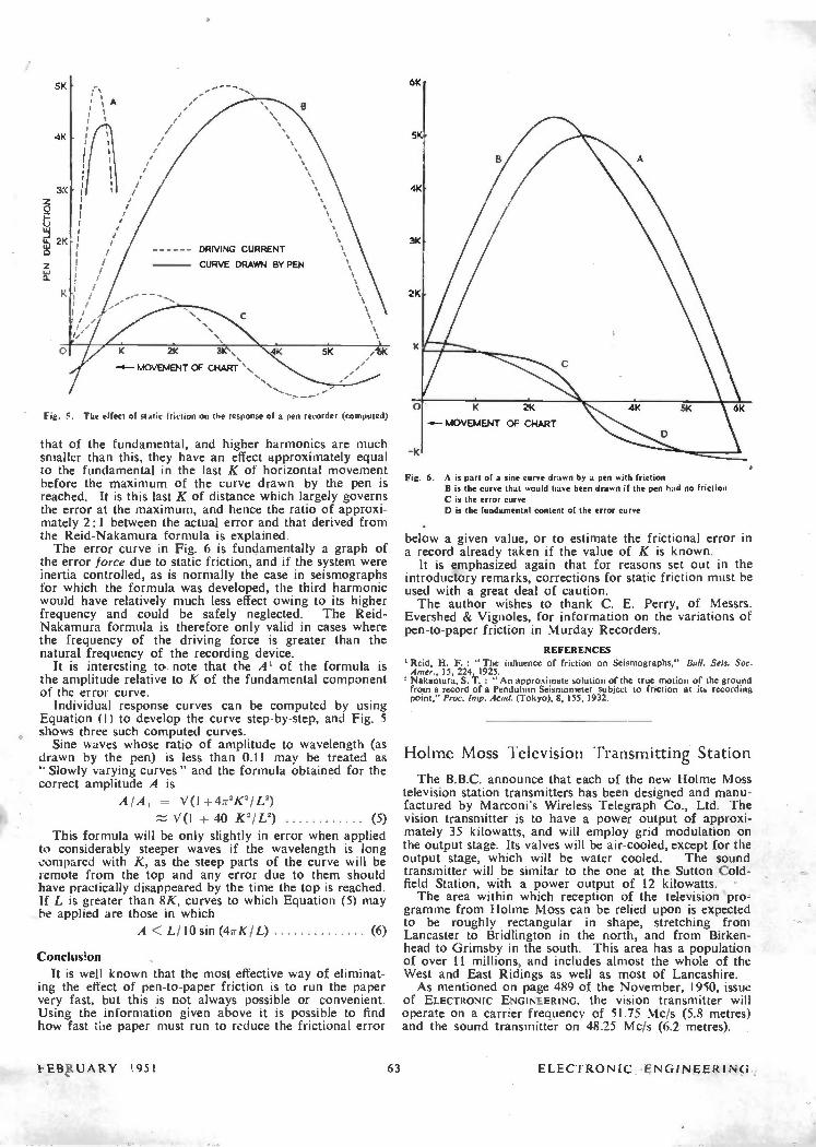
Fig. 5. The effect of static friction on the response of a pen recorder (computed)
that of the fundamental, and higher harmonics are much smaller than this, they have an effect approximately equal to the fundamental in the last K of horizontal movement before the maximum of the curve drawn by the pen is reached. It is this last K of distance which largely governs the error at the maximum, and hence the ratio of approxi-mately 2:1 between the actual error and that derived from the Reid-Nakamura formula is explained. The error curve in Fig. 6 is fundamentally a graph of
the error force due to static friction, and if the system were inertia controlled, as is normally the case in seismographs for which the formula was developed, the third harmonic would have relatively much less effect owing to its higher frequency and could be safely neglected. The Reid-Nakamura formula is therefore only valid in cases where the frequency of the driving force is greater than the natural frequency of the recording device.
It is interesting to.. note that the At of the formula is the amplitude relative to K of the fundamental component of the error curve.
Individual response curves can be computed by using Equation (1) to develop the curve step-by-step, and Fig. 5 shows three such computed curves.
Sine waves whose ratio of amplitude to wavelength (as drawn by the pen) is less than 0.11 may be treated as Slowly varying curves" and the formula obtained for the
correct amplitude A is
AIA, V(1+47;1C/L2)
V (1 + 40 K2/L2) (5)
This formula will be only slightly in error when applied to considerably steeper waves if the wavelength is long compared with K, as the steep parts of the curve will be remote from the top and any error due to them should have practically disappeared by the time the top is reached. If L is greater than 8K, curves to which Equation (5) may be applied are those in which
A <L110 sin (47K/L) (6)
Conclusion
It is well known that the most effective way of eliminat-ing the effect of pen-to-paper friction is to run the paper very fast, but this is not always possible or convenient. Using the information given above it is possible to find how fast the paper must run to reduce the frictional error
6K
5K
4K
3K
2K
2K
MOVEMENT OF CHART
Fig. 6. A is part of a sine curve drawn by a pen with friction B is the curve that would have been drawn if the pen had no friction C is the error curve D is the fundamental content of the error curse
6K
below a given value, or to estimate the frictional error in a record already taken if the value of K is known.
It is emphasized again that for reasons set out in the introductory remarks, corrections for static friction must be used with a great deal of caution. The author wishes to thank C. E. Perry, of Messrs.
Evershed & Vignoles, for information on the variations of pen-to-paper friction in Murday Recorders.
REFERENCES
Reid, H. F. : " The influence of friction on Seismographs," Bull. Seis. Soc. Amer., 15, 224, 1925. Nakamura, S. T. : "An approximate solution of the true motion of the ground from a record of a Pendulum Seismometer subject to friction at its recording point," Proc. Imp. Acad. (Tokyo), 8, 155, 1932.
Holme Moss Television Transmitting Station
The B.B.C. announce that each of the new Holme Moss television station transmitters has been designed and manu-factured by Marconi's Wireless Telegraph Co., Ltd. The vision transmitter is to have a power output of approxi-mately 35 kilowatts, and will employ grid modulation on the output stage. Its valves will be air-cooled, except for the output stage, which will be water cooled. The sound transmitter will be similar to the one at the Sutton Cold-field Station, with a power output of 12 kilowatts. The area within which reception of the television pro-
gramme from Holme Moss can be relied upon is expected to be roughly rectangular in shape, stretching from Lancaster to Bridlington in the north, and from Birken-head to Grimsby in the south. This area has a population of over 11 millions, and includes almost the whole of the West and East Ridings as well as most of Lancashire. As mentioned on page 489 of the November, 1950, issue
of ELECTRONIC ENGINEERING, the vision transmitter will operate on a carrier frequency of 51.75 Mc/s (5.8 metres) and the sound transmitter on 48.25 Mc/s (6.2 metres).
FEBRUARY 1951 63 ELECTRONIC ENGINEERING

A Choke-Coupled Phase-Invertor of High Accuracy By R. A. Seymour * and D. G. Tuckert
PHASE-IN VERTORS using resistance-loaded triode valves are well-known,' and if equal resistances are used
in anode and cathode circuits, then the anode and cathode voltages can be almost exactly equal and of opposite phase. It is often possible to make this circuit of adequate voltage-handling capacity, so that grid current can be avoided, but in many applications, e.g., a transformerless rectifier modulator recently described,' it is necessary to raise the applied voltage to the limit. In such a case, grid current may flow and, since it flows in the cathode resistor but not in the anode, it unbalances the outputs. This difficulty can be avoided by using a balanced-choke coupling as described below; the grid current may then be permitted to become as large as distortion considerations allow, while still retaining good balance of voltage and accuracy of phase. The same result could not be obtained by the use of an ordinary transformer circuit, since although a trans-former phase-invertor may give equal voltages and opposite phases with some accuracy, the phases will not correspond correctly to the phase of the applied signal owing to the large phase-shift introduced by the leakage
H.T.+
Fig. I. Choke-coup:ed phase inwertor
(blocking capacitors not shown)
inductance. This point is of great importance in all feed-back circuits, wheler they are feedback amplifiers, oscilla-tors, servo loops, etc. The circuit arrangement is shown in Fig. 1 and is
analyzed in terms of a general resistance load R which has the requirement that its centre point should remain at earth potential. In the case of a modulator, this corres-ponds to no carrier leak. The equivalent circuit is shown in Fig. 2. Here a grid-
current circuit is added in which Rn is the effective resis-tance from grid to cathode when grid current flows. The analysis has two objects, (a) to determine the voltage and phase-shift of the output (Vc) relative to the applied input voltage (e), and (b) to show that grid current does not seriously unbalance the output, although it does do so in the simple resistance-coupled phase-invertor.
(a) Voltage and Phase-shift of Circuit
Since the effect of grid current on the efficiency of the circuit must be small, it is adequate here to ignore the grid current circuit altogether. Then, since no current flows in —M, the point I must
be at earth potential. So VAC = 2Vc (where VAC = voltage from anode to
" Post Office Research Station. Royal Naval Scientific Service, Winer& Post Office Research Station.
cathode). Thus we have:
— 2Vc j2Ru(L + M) if j2Rw(L All 1 — ,u(e — Vc) — R + j2to(L + M) IL re R + j2cu(L
Now put 24,,(L + M) = X and solve for Vc.
µRX Then Vc —
+ 2)RX + 2r,,X + j2r,,R • e • • • (1)
so that the phase-shift between input (e) and output (Ve) is given by
tan — . R/ X exactly .. (2) + 2) R + 2rgt
and if we assume X >> R, the voltage gain is
µR Vc/e ( (3)
-F 2) R + 2r
From these equations we can see that the phase-shift (which is required to be small) is determined, as far as the choke is concerned, entirely by its shunt inductance, and the leakage inductance has no influence except for the very second-order effect that L + M will be slightly less than 2L. In a transformer coupling, as discussed earlier,
A
Fig. 2. Equivalent circuit for Fig.
-M
the leakage inductance may have a first-order effect on the phase-shift. Any self-capacitance or other stray capaci-tance may be included in the term X in Equation (2). It is clear that the anode-to-cathode coupling, which produces negative voltage-feedback, gives the effect of a low internal resistance in the valve, since the greater the amplification factor (µ) the smaller the phase-shift becomes.
Since the equivalent circuit is, in the absence of grid current, quite symmetrical about the point 1, it is evident that the voltage from anode to earth is in exact phase opposition to that from cathode to earth.
(b) Effect of Grid Current It can be seen almost by inspection of Fig. 1 that grid
current flowing from cathode to earth will not unbalance the output if the coupling between windings is perfect, and thus the mid-point of the load R will remain at earth poten-tial. It is perhaps more difficult to see this from the equiva-lent circuit of Fig. 2, but the analysis is quite simple. Ignoring r. (which can be considered as absorbed into R). the grid current flows into two paths at C. Consider a current ii flowing through L + M and —M to earth, and a current i, through R. L + M and —M. Then by equating voltages from C to 1, we have
. R + jtu(L + M) . 1, . 1,
jw(L + M)
ELECTRONIC ENGINEERING 64 FEBRUARY 1951

and if Vo" is the voltage from cathode to earth due to grid current, then
= [R + jw(L + M)] — + Diu) Al
M • = j2[R + jwL — L -FM (R + jw(L + M)}] (4)
Now if the coupling is perfect, M = L, and then
Vc'IRI2 (5) which means that the centre-point of R is at earth potential.
When the coupling is not perfect, i, is given by Equation (4) and the out-of-balance voltage at the centre-point of R is given by:
Vc' — i,R/ 2
= (L — M' [2(L + M) + jw (6)
Note that if w(L M)› R,
¡2 iG where iG = total grid current.
Thus the out-of-balance voltage is approximately pro-portional to the product of grid current and leakage reac-tance. In practice, therefore, design must aim at a high total inductance to keep the phase errors small, and a low leakage inductance to keep the effect of grid current small.
The above analysis ignores the presence of an E.M.F.
M ir0 in series with ri, due to the feedback effect, but this is evidently quite justifiable because it has already been shown that the circuit is balanced in any case to signals in the r, circuit.
REFERENCES
Sowerby, J. M. : " Some Notes on Phase-Splitters," Wireles.s World, 55, 492, Dec., 1949.
' Tucker, D. G. : " Balanced Rectifier Modulators Without Transformers." Electronic Engineering, 22, 139, 1950.
A Null Method of Measuring the Gain and Phase Comparatively Low. Frequency Amplifiers
By T. Baldwin, A.M.I.Mech. E. * and J. H. Littlewood, M.Sc. *
THE following is a description of a method used to determine the gain and phase characteristics of low and
medium frequency amplifiers. It has been found con-venient in practice and gives repeatable results, without requiring more complicated equipmentt than an accurate attenuator calibrated in 0.1 db steps, an oscillograph, a variable decade capacitor, a known resistor and a variable frequency oscillator giving an adequate output. The gain and phase shift in the amplifier are cancelled out by equal and opposite gain and phase shift. Consequently, the measure-ments are made under overall zero conditions of gain and phase shift and thus the method can be regarded as null.
In testing low and medium frequency amplifiers, the following is a common procedure:
(i) The same A c. voltage is applied to the X and Y
ATTENUATOR AMPLIFIER
Fig. I. Usual circuit to measure voltage gain D
Fig. 2. Modified Circuit to measure voltage gain and phase shift
OSC EARTH
plates of a cathode-ray oscilloscope. For simplicity it will be assumed that push-pull deflexion is not employed. The slope of the resulting line on the e.R.T. is indicated by the points of two pins secured to the tube face by plasticine.
(i# The circuit shown in Fig. 1 is connected up. It is usual to place a resistor R in series with the attenua-tor, R being greater than the characteristic impedance (RA), of the attenuator. This is because the potential
• ledeatrIc Research Department, British Railways.,
Shift of
necessary to deflect the oscilloscope beam is greater than is permissible across the attenuator input. The resistor must be free from inductive or capacitative errors, and it is convenient to make it an even multiple of the characteristic impedance of the attenuator (e.g., 10 x RA). Provided that the fre-quency is such that there is no phase-shift in the amplifier, the attenuator can be adjusted so that the resulting straight line on the tube face intersects the two pin points. In this condition the attenuation.— through R and the attenuator is the inverse of the fractional gain in the amplifier. If the fractional attenuation in the attenuator is IIA the total frac-tional attenuation is: RAIA.R and the fractional gain of the amplifier is: A . RIR A
A
ATTENUATOR AMPLIFIER
05C EARTH
Difficulties are encountered, however, when the test fre quencies are such that phase shift is present in the amplifier, because the straight line on the tube face opens out into an ellipse which may become nearly circular, and under such conditions it is difficult to assign a precise direction to the major axis. The method to be described obviates this difficulty, and at all reasonable frequencies enables final
t A more elaborate equipment with an accuracy of measurement ol" approximately ±0.2° of phase was demonstrated by The Royal Aircraft
Establishment, Ministry of Supply, at the Physical Society Exhibition in 1948.
FEBRUARY 1951 65 ELECTRONIC ENGINEERING
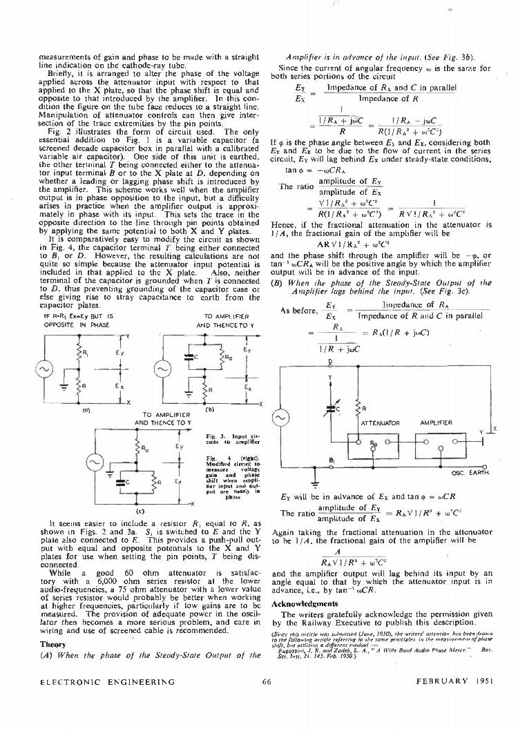
measurements of gain and phase to be made with a straight line indication on the cathode-ray tube.
Briefly, it is arranged to alter the phase of the voltage applied across the attenuator input with respect to that applied to the X plate, so that the phase shift is equal and opposite to that introduced by the amplifier. In this con-dition the figure on the tube face reduces to a straight line. Manipulation of attenuator controls can then give inter-section of the trace extremities by the pin points.
Fig. 2 illustrates the form of circuit used. The only essential addition to Fig. 1 is a variable capacitor (a screened decade capacitor box in parallel with a calibrated variable air capacitor). One side of this unit is earthed, the other terminal T being connected either to the attenua-tor input terminal B or to the X plate at D, depending on whether a leading or lagging phase shift is introduced by the amplifier. This scheme works well when the amplifier output is in phase opposition to the input, but a difficulty arises in practice when the amplifier output is approxi-mately in phase with its input. This sets the trace in the opposite direction to the line through pin points obtained by applying the same potential to both X and Y plates.
It is comparatively easy to modify the circuit as shown in Fig. 4, the capacitor terminal T being either connected to B, or D. However, the resulting calculations are not quite so simple because the attenuator input potential is included in that applied to the X plate. Also, neither terminal of the capacitor is grounded when T is connected to D, thus preventing grounding of the capacitor case or else giving rise to stray capacitance to earth from the capacitor plates. IF R.R Ex-Ey BUT IS
OPPOSITE IN PHASE
(a) TO AMPLIFIER
AND THENCE TO Y
TO AMPLIFIER
AND THENCE TO Y
Fig. 3. Input cir-cuits to amplifier
Fig. 4 (right). Modified circuit to measure voltage gain and phase shift when ampli-fier input and out-put are nearly in
phase
(c)
It seems easier to include a resistor R, equal to R, as shown in Figs. 2 and 3a. S, is switched to E and the Y plate also connected to E. This provides a push-pull out-put with equal and opposite potentials to the X and Y plates for use when setting the pin points, T being dis-connected. While a good 60 ohm attenuator is satisfac-
tory with a 6,000 ohm series resistor at the lower audio-frequencies, a 75 ohm attenuator with a lower value of series resistor would probably be better when working at higher frequencies, particularly if low gains are to be measured. The provision of adequate power in the oscil-lator then becomes a more serious problem, and care in wiring and use of screened cable is recommended.
Theory
(A) When the phase of the Steady-State Output of the
Amplifier is in advance of the input. (See Fig. 3b).
Since the current of angular frequency to is the same for both series portions of the circuit
Ey Impedance of RA and C in parallel
Ex Impedance of R
1
— 1/RA + jceC 1 /RA — jueC - RO I RA' + oi2C2)
If is the phase angle between Ey and Ex, considering both Ey and Ex to be due to the flow of current in the series circuit, Ey will lag behind Ex under steady-state conditions,
tan 95 — wCRA
amplitude of Ey
amplitude of Ex
V 11 RA' + (02C2 1
- R(11 RA2 w2C2) - RV 1 + (.02C' Hence, if the fractional attenuation in the attenuator is 11A, the fractional gain of the amplifier will be
AR V1 / RA' + w2C2
and the phase shift through the amplifier will be -- 0, or tan-1 wCRA will be the positive angle by which the amplifier output will be in advance of the input.
(B) When the phase of the Steady-State Output of the Amplifier lags behind the input. (See Fig. 3c).
EY Impedance of RA
Ex • Impedance of R and C in parallel
RA — RA(l 1 R + j(C)
1
The ratio
As before,
1/R + itoC
D
AT T ENUATOR AMPLIFIER
B1
o o
Y X
O 05C EARTH
Ey will be in advance of Ex and tan q = 0,CR
amplitude of Ey The ratio amplitude of Ex — RAVI/R2 1 +
Again taking the fractional attenuation in the attenuator to be 11A, the fractional gain of the amplifier will be
A
RAN/ 11R2 + (X'
and the amplifier output will lag behind its input by an angle equal to that by which the attenuator input is in advance, i.e., by tan-1 o)CR.
Acknowledgments The writers gratefully acknowledge the permission given
by the Railway Executive to publish this description. (Since this article was submitted (June, 1950), the writers' attention has been drawn to the following article referring to the some principles in the measurement of phase sh(t, but utilizing a different method:—
Ragazzini, J. R. and Zadeh, L. A.," A Wide Band Audio Phase Meter." Rev. Sci. Inst. 21. 145. Feb. 1950.)
ELECTRONIC ENGINEERING 66 FEBRUARY 1951

A Simple Analogue Computor for Fourier Analysis and Synthesis
By J. H. Bowen, B.Sc., and T. E. Burnup, D.Sc.
A circuit containing only standard electrical components is made to solve the tedious integrals encountered in the study of the responses of electro-mechanical systems by Fourier methods.
Typical applications are briefly described.
THE designer of automatic control systems often includes, I in. his electro-mechanical networks, devices with un-known transfer functions. For example, a primary measuring element (e.g., a thermocouple) may operate a self-balancing potentiometer, from which a re-transmitting potentiometer may feed into the rest of the control system. In the author's experience even the best manufacturers do not specify the transfer functions of these instruments. A similar difficulty frequently arises regarding the process itself, where the steady-state characteristic may be precisely known, but the differential equation governing the tran-sient behaviour is very difficult to determine.
In such cases the value of the method of " harmonic testing" is well known, giving the steady amplitude and phase of response, for a steady sinusoidal input of constant amplitude and with frequency varied over the range of interest. The curves of amplitude S(w) and phase 1,(0)) vs. frequency, thus obtained, exactly specify, in the case of linear circuit elements, the response to any input, and are conveniently regarded as secondary, derived parameters of the system. In this frequency characteristic form the net-, work elements may be combined and calculations made of maximum gain and stability margins. Finally, however, the main interest will be the transient response of the whole system for various types of input. If the frequency charac-teristic of any input is analysed by means of the Fourier integral formula, and combined for each frequency with the response characteristic, corresponding amplitudes being multiplied together and phase angles added, the Fourier synthesis of the compound frequency characteristic is the required transient response. In particular, the response to a 8-function or unit impulse input is easily obtained since this function has a frequency characteristic of unit ampli-tude and zero phase angle. In this case, the transient response is given by:
co G(r) = 11 7rf S(w) cos [0(0)) + zu]deo
when G(r) is the response at the instant of time rsecs. after the application of the impulse.
If S(w) and 0(w) are recognizable mathematical functions, the integral may either be solved directly or resolved into partial fractions, set up on the electrolytic tank, and solved by determining the residues at the poles.' However, as explained above, often S(w) and 0(w) have been determined experimentally and graphical integration is indicated. Since this must be repeated for a reasonable number of values of the parameter 7, the calculation is laborious. This paper describes a simple analogue computor which has been designed to solve this integral with sufficient accuracy. A more accurate device has been described in Ref. 3. A fairly obvious extension of the following reasoning
also permits the computor to solve problems of Fourier analysis, thus:
03
=j1'3(i) cos I.t)/ dt and B(0)) =./ GO) sin 0,1 (It—co —co
Here G(t) is a transient, non-recurrent function of time. For example, the step-function response of a servo-
mechanism may by this means be transformed into its fre-quency characteristics.
Theory
The integral is re-written as:
G (7 ) = I / 7 [f,s(w) cos cos ro., d _ o S(w) sin yib(w) sin 70, do)]
• co
Put S(w) cos 0(01) = A (w) and S(w) sin cp(w) = B(w)
Approximating to finite differences:
to= n, 2w, 1 n, • • • oh 7r G(7) 1/ TI
A(0)) cos Tw îw 200 n,...
B(0)) sin TO) 41
Si MECH. .... OSC.
UNISELECTOR r 1 2 3
•—
S2 R2
-4VeR2'
INSULATING "? SEGMENT
Fig. 1. Circuit
• •-
24 25 -1
— 50V.
200
X e STANDARD TELEPHONE RELAY TYPE CDT 4602
R1A 5OOt. R2= R2' E 200.a.
CI E 4µF LOW LOSS. C2 -z- 4,u.F
R3E 25k (25 OFF) R4 A !Mil
V.VE VALVE VOLTMETER 0-5V.
A a SINGLE STAGE D C. AMPLIFIER, APPROX. GAIN 200
details of the analogue computor
The larger n. the more accurately the approximation holds, exactly as in a mid-ordinate summation. The integral is normally convergent, since at sufficiently
high frequencies, most frequency-dependent devices become asymptotic to an attenuation-frequency slope of —6 N db./ octave where N is an integer, dependent upon the number of time-constants involved, and on the number of steady state integrations occurring in the network. The phase at the same time approaches asymptotically N 77/2 radians. The procedure is, therefore, either to extend the integration range to a value (0 where A(w) and B(w) are so attenuated as to be negligible; or, preferably, to use the computor to integrate from Wo to Oh when S(wi) is a point on the final asymptotic slope although not necessarily greatly attenuated. The remaining integral, from w, to is calculated. (See App. A).
FEBRUARY 1951 67 ELECTRONIC ENGINEERING

o
The expressions (A(w) cos 7-w 8w and
B(w) sin rw &,) are separately set up and evaluated.
.i.nce physical integration is most easily achieved with respect to time, the variable w becomes time in the analogue. The basic and analogue expressions are written for com-parison:
G(7) = A(w) cos TW 8W V(P)=Q(t)(Vm..cos 0)81
10 = WI in,2w,/n,..w, t=tiln,2111n,..11 cos pl) is obtained from a low-frequency oscillator,
the same, in fact, as used for the sine-wave tests already described. Q(t) is a voltage-dividing potentiometer set up to vary with time to represent the variation of A(w) with w. Consideration of the constants of proportionality connect-ing the expressions will be deferred until the actual circuit has been discussed.
Circuit Arrangements. General
The variation of Q(t) is achieved by means of a Post Office type 25-contact 5-bank uniselector, one bank not being used. 24 contacts are connected each to a 3W 10k radio-type potentiometer. This was considered simpler than the alternative of a single potentiometer with 24 adjustable tapping points, since standard apparatus could be used. One bank of the uniselector is used to switch in one poten-tiometer at a time to avoid undue loading on the previous circuit. The uniselector is externally pulsed to complete its travel in about 5 secs. The potentiometers having been pre-set, the voltage appearing at the uniselector wiper follows the law V[Q(t)]. Also V from the oscillator = cos pl or sin pt according to the instant at which Q(t) commences on the cycle of V, when the wipers step off the 25th contact which is earthed. This is achieved by a switching inter-connexion between oscillator and uniselector. The resulting voltage Vina. Q(t) cos wt is supplied to a
standard integrator (Fig. 1) in which the amplifier will be recognized as providing a " virtual earth ". R4 is made variable for scaling purposes as described below. 0 is a mechanical oscillator, generating a sine wave of
voltage on the slider of R1, at frequencies between 1 cycle/ min. and 2 cycles/sec. according to the driven speed. When voltage is applied to the pulsating relay, XI a opens
and XI b closes applying voltage to the uniselector drive magnet. This does not step on until X1 b opens, which occurs when C2 has charged. On reaching contact 25, C2 is shorted via an earth on bank 3 and the wipers remain in this home position. The earth line to C2 is broken by momentarily opening Si and S2, which are in parallel the selector then stepping on a complete cycle. S2 is a second oscillating wiper moving together with the main oscillator brush arm, but running on an earthed strip having an insulating segment whose position is adjusted to trigger off the uniselector at the appropriate instant according to the sine or cosine requirement.
Operating Details
The oscillator wiper is positioned at its mid-point of travel, then with S3 and SS each set to "a", R2 and R2' are adjusted for a balanced input shown by zero voltage on V.V. The wiper is now set to maximum travel and R3(25) set for full scale deflexion on V.V. S3 is set to b, and R3 (1 to 24) set up to the 24 mid-ordinate values of A(w). If these values are < 1, no difficulty arises, but if a resonant peak exists in the amplitude characteristic, a read-ing > 1 may be required on a voltmeter whose full scale is being treated as 0-1. If a back-off setting is provided on V.V. this may be used to extend the scale, otherwise
g
brIl ANALOGUE COOAPUTER • Skl) PHAS
sH1 T
t 2 ..,
6 RESPONSE
CALCULATED '6 RESPONSE 6 0
re ' /
1 6 r FREQUENCY
r •• 1 CKARACTERISTICS
r• 2 1-- r - ACTUAL UNIT FUNCTION RESPONSE
10
24 IUiUPUI LATED AND COMPUTED , RESPONSES
CORFIECNON r SEE
FOR RANGE APP A
6). -or co
e 1 r
0 SCALE OP
420 Se, 60r. 1
(M.) • 60300
2 •S ,25 ry SCALE OF
T SECS
Fig. 2. Transient characte r ' of a moving-coil self recording voltmeter
A(w) must be norma ized to 1, and the final integral multi-plied by the same factor. If negative values of A(w) exist, the potentiometers representing these ordinates should be set to 0, the + and — integrals being determined separately and finally subtracted. The integrator is now calibrated by setting SS to b, 53
to a, and breaking S1 and S2, which allows the uniselector to step one cycle. S4, which is a push-button switch, is kept open during this operation, and a voltage appears on Cl which is a summation of the unit voltages picked off bank 2, multiplied by the time of dwell on each contact, i.e., 8.
G(r) A(w) cos rw&o
(r) =
V(p)=Q(i) V max. cos pt 81
Ph 2W. .
n n
We make: V max. Q(t) = A(w) and TO) = pi
G(r)= 0414 V(P) Now if Vc is the voltage appearing on the capacitor,
and Vi is the voltage input to R4,
Vc=IVi/R4 = 1/R4 Q(t)
ti/24 t, G(r) =- R4 WI/i) Vc
and G(r)/w, = R411, Vc. Note: G(r)/w, = average value of G(r). In the calibration experiment, V.,. Q0)=1 and cos pt. =1, p being zero •
I— n n
ïl = it/w1 Sed
V max. cos pt. 8: = 1/R4 V(p1)
(1) =
t = 4/24, 24/24, . . . t, Vc1 = t1/R4 when Vc1 is the reading of V.V. in the
calibration experiment. R4 is adjusted till Vc1 = 1. Then Vc reads G(r) av direct which is preferred to reading G(r), as the average value of the same order of magnitude as
Q(t), whereas the integral will generally be greater by a factor of about 10.
Following calibration, S3 is set to b, the uniselector sent through one cycle, and Vc noted giving G(o)ay. The pro-cedure is repeated for as many values of oscillator fre-quency as values of r are required in the final time plot of the transient. The appropriate value of r in secs, is given by r = (mat.), when (ea is the radian measure of the angle reached by the oscillator when the uniselector arrives at contact 24 representing t,. In practice, at the low frequencies concerned, it is easy to adjust the speed of the
ELECTRONIC ENGINEERING 68 FEBRUARY 1951

co Radians
Fie. 3. Fourier analysis and re-synthesis of a short pulse
oscillator until full travel of the uniselector corresponds with multiples of, say, 1/12 cycle of the oscillator fre-quency. r then increases in multiples of T,/12 where T, is the period of the highest frequency w,.
Conclusions To illustrate the accuracy of computation, Fig. 2 shows
calculated and computed values of the transient response of an Elliott 0-5V recording voltmeter. The integrals of the unit impulse responses are also plotted as step-function responses, and the experimentally obtained step function response is included. Agreement is in this case better than might normally be anticipated, the sources of error being:
(1) The mid-ordinate approximation. (2) The limitations of the standard components used
throughout; e.g. non-linearity of valve voltmeter, capacitor leakage, the approximation of the " virtual earth."
(3) The voltmeter scale used which only permits reading to ±- 1 per cent of full scale.
For thèse reasons, the expected accuracy is put at about -± 5 per cent of the maximum reading; but this is con-
sidered normally sufficient for the design calculations in-dicated at the beginning of this article.
Since this paper was written, a computor independently developed in the U.S.A. for the same purpose has been described.' The principle, however, is quite different, and in view of the enormous disparity between the costliness of the two methods, it is felt that this paper may still serve a useful purpose. Fig. 3 is included for comparison with Fig. 8(C) of that paper, the main difference being that the Gibbs effect is more strongly marked in the computor we describe. This is ascribed to the fact that the equivalent of 39 steps are used in the American device; and it is now felt that a 50 step uniselector would be a useful improve-ment. Also, in Fig. 2, the double transformation process has introduced double errors.
Appendix A As an example, in the very common case of two major
time lags, when w>w„ S(w) —> 1/T2(02 i.e.-12 db. per octave.
Also 0(0 —Ir. Then A(0.))= — 1/ T'w2. B(w) -= O.
The integral I = 11 rT2 Cos t I w2 dw.
When I = o, 1(0) = U ri' [1 /o) toi
=- —1 /7rT2wi = co fWhen t>0 1(1) = — I Irr COS /to c/(t0
CO
tto, tzw2 co co
t
= irr(_[COS to)]
/to •021 11:oi
= — tbrr(-1- COS (ta i
sin tw
tw
— /r/2 + Si (twi) Iw
Where Si (tw,) is the sine integral function commonly tabulated.
REFERENCES
Boothroyd, Cherry and Makar. Electrolytic tank and transient response. Pt. 1, No. 99, May 1949. Lehman. Harmonic analyzer and synthesizer. Electronics Nov. 1949. Furth R. and Pringle, R. W. : A photo-electric Fourier transformer. Phil. Mat. 37, 264, 1946.
A High-Stability Single-Frequency Audio Source
By W. E. Brunt
Pr HERE are many uses for a single-frequency audio source especially when it is simple, inexpensive and
possesses frequency stability, accuracy and waveform of a fairly high order. The unit to be described possesses all the above features, yet presents few difficulties in construc-tion.
Fundamentally it is a two-stage tuned amplifier. The input is coupled to the H.T. rectifier via a single-stage differentiator and, the amplifier being tuned to 400 c/s, the eighth harmonic is selected and amplified. The excellence of the output waveform is largely con-
trolled by the " Q " of the tuned circuits. In the model as constructed " Q " is approximately 20, and the peak value of all distortion and hum products does not exceed 1 per cent. This is more than adequate for all normal purposes. In fact, it is probably true to say that no simple signal generator of the conventional types can approach this per-formance. Furthermore, the frequency, accuracy and stability are those of the supply mains, and this (power
TO HT.
FILTER INPUT
cut periods excepted) is a fraction of 1 per cent. The frequency of 400 c/s was chosen because it is in
universal use for amplifier and receiver measurements and because it is probably the most useful for general bridge work. In construction, it is important to ensure that the coils used are sensibly of the " constant inductance" type, and that they are tuned to the desired frequency. The valves and coils were those to hand, and any others with similar characteristics may be used; in fact, EF50 or VR65 valves would be rather better.
FEBRUARY 1951 69 ELECTRONIC ENGINEERING

Letters to the Editor (We do not hold ourselves responsible for the opinions of our correspondents)
Positive Feedback in A.F. Amplifiers
DEAR SIR,—Concerning Mr. C. H. Banthorpe's contribution on audio-frequency positive feedback, I feel that your readers may possibly be in-terested in an amplifier which I con-structed recently for A.c/ D.C. operation for 12 watts output, which features nega-tive feedback across three stages to cancel odd harmonic distortion, and positive feedback from the triode con-nected EF36 phase-splitter to the EF36 pentode driver stage, cathode coupled, for the combined purpose of raising the gain and balancing the upper frequencies on the cathode output side of the phase-splitter (see below).
It was found best to leave the phase-splitter cathode undecoupled as this gives smoother positive feedback control and a greater stable maximum gain. The extra smoothing for the first two stages is essential owing to the high gain, about 3 x 10⁶ maximum. The .005 µF. anode to anode output capacitor is essential to prevent mainly supersonic oscillation.
R. MICHAEL CROSS,
Margate, Kent.
Mr. Banthorpe replies: DEAR SIR,—I am pleased to see that
Mr. Cross uses a similar arrangement to mine to get positive feedback and his amplifier looks quite interesting in several respects. It would be informative to have his comments on positive feedback and the performance generally.
C. H. BANTHORPE, Hayes, Middlesex.
DEAR SIR,—While not disagreeing with the general principle put forward by your contributor, Mr. Banthorpe, in your November, 1950, issue, I think the actual circuit he gives with the volume control placed between the triode and the output pentode should be used only with con-siderable caution.
The 12-watt A.C./D.C. amplifier using negative feedback across three stages as described in the letter from Mr. Michael
Cross
M1C
GRAM
O
01)...2F;1/(r‘
0 5F
470 kn
05 mct
0-SMO.
470
kn.
0 I
With the circuit valves given, the triode can not give more than about 30 volts peak at the anode, when the feedback voltage developed across the 4.7k cathode resistor will be about 1.5 volts and the grid to cathode voltages also about 1.5 volts. The maximum input voltage that can be handled, therefore, cannot be more than three volts peak; and since in a conventional superhet the controlled valves will require at least 20 volts of A.V.C. bias for cut-off, there will be a serious risk that the A.F. triode will be overloaded on strong signals.
E. F. Goo!),
Malvern, Worcs.
Mr. Banthorpe replies: DEAR SIR,—Mr. E. F. Good is quite
right to point out that it is possible to overload the triode valve in the circuit given, but it is of little practical signifi-cance in the application shown, which is actually part of a small receiver using a small frame aerial. Mr. Good mentions a voltage of 30V at the triode anode, but this would never be needed, and if the volume control position is reduced to prevent overloading the output stage, the triode can cathode-follow better, and handle a bigger input voltage without dis-tortion occurring. He also mentions 20 volts of A.V.C. bias to cut off the con-trolled valves, but, of course, if they were cut off there could be no A.V.C. bias. In the receiver mentioned, a signal into the frequency changer grid of approxi-mately 10 millivolts is needed before the triode causes distortion, and this is a larger signal than is generated by most stations. In the odd situation where trouble might te experienced, the frame aerial can be rotated to prevent over-loading. As a matter of interest, with this input, approximately 5V of A.V.C. bias is generated. In many applications it may be best to put the volume control in the triode input, but this has no con-nexion with the use of positive and nega-
ivVy
10kn 2915k
I 50kn
01u.F
EF 36
I 5 1,0
0-10 ka
0 VA,
0.1p.F
24k
26kn.
750
ELECTRONIC ENGINEERING
o
tivc feedback. The circuit given merely shows a method of using feedback, and also how the circuit lends itself to gain control at high signal levels with the corresponding reduction of noise due to the control, but it is probably a good thing for your readers to know how distortion can occur and I am pleased Mr. Good has raised the matter.
C. H. BANTHORPE,
Hayes, Middlesex.
Precision A.C. Voltage Stabilizers DEAR SIR,—In an article under the
above heading (October issue, page 426) Dr. Patchett criticises a statement of mine' to the effect that a bridge voltage regulator constructed from Siemens Types 1 and 2 barretters has no appre-ciable thermal time lag. He appears to have overlooked the fact that this state-ment referred not to iron/hydrogen resistors, but to the Siemens tungsten/ hydrogen type, in which the ballast action depends upon the variable gas density principle which forms the subject of British Patent No. 378877. Dr. Patchett's statement that a barretter, after a change in voltage, takes several minutes to settle down to the new equilibrium condition, applies only to the iron/ hydrogen type: oscillographic tests' prove that for the Tl tungsten/hydrovn ballast resistor the corresponding period is 50 milliseconds.
C. MORTON, Chelsea Polytechnic, S.W.3.
Journal Sci. Inst. 21, p. 15, 1944. Wireless World, Nov. 15th. 1935.
Dr. Patchett replies: DEAR SIR,-1 am interested in the
remarks of Mr. Morton concerning the Siemen's tungsten hydrogen type bar-rettei's. I have had no experience of this type and did not realize that the Siemen's barretter referred to in his reference' operated on a different principle, no
•
MUI/1
005 e F
+220v
•-•
750
70 FEBRUARY 1951

mention of this important fact beinggiven in his article. My remarks con-cerning barretters were intended to referto the hydrogen iron type and I regretthis misunderstanding.
G. N. PATCHETT.Eccleshill, Bradford.
Magnetic LensesDEAR S1R,-In teaching this subject, it
has been found that a more completeunderstanding of the complex focusingaction of the short magnetic field may begained by students considering this totake place in three stages. The first andlast of these correspond with those givenby Mr. Overton in his letter in the Sep-tember, 1950, issue concerning the article" Permanent Magnet Lenses for Televi-sion Tubes ", while the intermediate stagecorresponds with that used by Mr.Hadfield in his reply to Mr. Overton.Clearly these three stages will not be dis-tinct and separate but will each mergewith the next as the electrons proceedthrough them. Thus the strong axialcomponent of velocity of the divergentelectrons will first react with the rela-tively strong radial field componentresulting in the path becoming curved intwo directions. First, the transverseradial field will result in deflexion of theelectrons in a similar way to that whichoccurs with normal magnetic deflexion.The plane of this track would, in auniform transverse field, be normal to theoriginal radial velocity. However, thefield is radial and since the deflectingforce must be perpendicular to both theaxial motion of the electron and to thefield direction the trajectory must alsocurve round the axis of the tube. Thecombination of these two deflexions willtherefore produce a resultant motion akinto the commencement of a spiral. Theeffect of the original radial velocity com-ponent, which has so far not beendirectly affected, is to carry the spiralaway from the tube axis.
Care must be exercised at this point toavoid the assumption that the spiral pathis followed for anything more than avery small fraction of a complete turn.In fact, a continuing spiral path wouldnot be produced and in any case the totalrotation of the image after passing rightthrough the lens is, in practical cases,appreciably less than 90°-neglecting theinversion of the image. Thus no directfocusing action results from this initialdeflexion, although the additional lateralmotion introduced results in a morepowerful convergent action in the centralaxial zone of the field than would occur
with the original weak radial velocitycomponent alone.
The remaining axial velocity will carrythe electron into the central axial fieldand the component of the skew motionwhich is perpendicular to this will pro-duce a further curvature of the trajectoryin a plane which is normal to the tubeaxis and which advances along it withthe axial velocity of the electron. Theradius of this curvature will decrease upto the point of maximum axial fieldstrength and then increase again and,provided that the action is sufficientlystrong, will result in the originaldivergency being destroyed and thenreplaced by a convergency. This part ofthe action is seen to be similar to thatproduced by a uniform axial field uponelectrons having radial components ofvelocity.
The final accurate direction of theelectrons towards the axis at the requiredfocus is accomplished by the last sectionof the field, i.e., the second radial fieldzone, in which a skewing action occurssimilar in nature, but reversed in direc-tion, because of the reversed radial fielddirection, to that occurring in the firstradial zone. The complete trajectorymay thus be depicted diagrammatically,as shown below.
For satisfactory paraxial image forma-tion the deviation suffered by the elec-trons must increase with their divergency.This will result from the increase inradial field with distance from the axisin the outer radial field zones where themore divergent electrons will undergo astronger skewing action. Assuming thatthe central axial field is constant acrossa small cross section about the axis, thehigher transverse velocities of the morestrongly divergent electrons will producea greater deviation, so that all the elec-trons within a beam which is not toostrongly divergent will be brought to acommon focus.
Referring to Mr. Hadfield's diagramsin his reply to Mr. Overton it will beseen that in Figs. 2 and 3 the paths takenby the electrons after passing throughthe lens are shown as curved, in factFig. 3 also shows two foci, in spite of theabsence of any appreciable fields beyondthe lens.
Regarding the rotation of the image. amathematical analysis of the lens actionshows that the magnitude of this isdirectly proportional to the integral ofthe axial field along the axis. Hence,while it is agreed that a stronger magnetwill produce greater rotation, redistribu-tion of the field alone will not alter theangle through which the image is rotatedas claimed by Mr. Hadfield.
The numerals 1 and 3 refer to the action occurring in the outer radial field zones, while 2 refereto that in the central axial zone. See Mr. Dive's letter on Magnetic Lenses
PLAN
ELEVATION
END ELEVATION
In Mr. Overton's letter he asked forevidence in support of the claim that for" optimum focusing " a particular fielddistribution is required and since no replyto this point was included by Mr.Hadfield perhaps I may be permitted toraise it again. I understand that theexpression which is quoted represents thefield distribution obtained in certainimmersion objective lenses and that it isderived empirically, its usefulness lyingin the means which it provides for inte-gration of the axial field in the calcula-tion of focal lengths.
In conclusion may I query Mr.Hadfield's statement that the electrontrajectory indicated in Fig. 1 in hisoriginal article " was not the most usualcase and probably only occurs remotelyunder extreme conditions." The captionto the diagram itself states that it is a" representation of magnetic focusing ofa cathode-ray tube " and so far as onecan see the conditions prevailing in allmagnetically focused tubes are such as topreclude the possibility of this kind offocusing action from taking place. Thiswill be so because the beam, after pass-ing through the focusing field, proceedstowards the screen through a virtuallyfield -free space except for deflexion and/or post deflexion acceleration fieldswhich, in any event, would not be co-existent and would not, therefore, pro-duce a complex trajectory.
L. G. DIVE,B.B.C. Engineering Training
Department,Evesham, Worcs.
Measurement of Noise in ResistorsDear Sir,-The article by Mr. Oakes
on " The Measurement of Noise inResistors " is very interesting, but surelythe circuit of Figure 10 on page 469 isnot a practical one, for the noise out-put would be very small in view of thelow internal resistance of the battery.Also, the magnitude would depend onthe internal resistance, which variesduring the life of the battery. Perhapsa series resistor between the top of thebattery and the sliding contact has beenaccidentally omitted in the diagram.
A. M. ANDREW,Glasgow.
Mr. Oakes replies:Dear Sir,-Replying to Mr. Andrew's
letter I would point out that he shouldhave noticed in Figure 10 that the noiseoutput will be developed across Ry anda portion of R; therefore the suggestedseries resistor is unnecessary, its functionalready being fulfilled by Ry. As Mr.Andrew quite correctly notes, theinternal resistance of the battery is small,in fact a fraction of a percent of Ry.The magnitude of the noise outputtherefore will be virtually independentof the internal resistance.
Regarding his suggestion that thisdiagram, Figure 10; is " surely not apractical one ", in many other places inthis country and abroad thousands oftests have been carried out successfullyin this way.
FRANCIS OAKES,
London, N.W.3.
FEBRUARY 1951 71 ELECTRONIC ENGINEERING

ELECTRONIC EQUIPMENTA selection of the more interesting apparatus, components and accessories compiled from information
supplied by the manufacturers
CondUctivity Meter(Illustrated below)
THIS instrument is designed to give adirect reading of the ratio of the
conductivity of two liquids under con-tinuous flow conditions. It consists oftwo units, the larger containing all theelectronic parts (oscillator, meter, etc.)and the smaller of the liquid parts (con-ductivity cells). This ensures that the elec-tronic parts cannot be ruined by leakagefrom the cells.
The instrument works directly off the200-250 volt A.C. mains and consists ofa stable 1,000 cycle oscillator to avoidpolarization, the output of which isapplied to the conductivity cells. Theseare arranged as two arms of a bridge,the output of which is fed to a valvevoltmeter consisting of a twin triode and4 -in. square milliameter. The milliameteris normally supplied marked 0-1 mA with100 divisions, a conversion table beingrequired to interpret the reading of milli-amperes in terms of conductivity ratio.If the range of ratio of conductivity isknown the meter could be suppliedscaled directly in ratios, in which casefull scale on the meter can be anythingfrom a ratio 1:1 up to 6:1 while theconductivity range can be from 10,4mhos to 100,000µ mhos with appropriatecells. The meter is provided with anadjustable contact which can be suppliedto make contact either on a falling orrising current (or ratio). This contactthen closes an auxiliary relay with con-tacts rated at 2A 230V A.C. on non -inductive loads which can be used toswitch external circuits. In addition asecond relay (with similarly rated con-tacts) also closes, but this can be de-energized by the push button on thefront panel without affecting the firstrelay. The contacts on this relay are in-tended to set off an audible alarm. Thisalarm circuit will in fact work everytime the meter contacts close, whether
ELECTRONIC ENGINEERING
the alarm has been switched off by thepush button or not.
The conductivity cells are made ofperspex tubes with monel electrodes whichare easily demountable for cleaning. Theliquid is introduced via unions designedfor 3/16 in. internal bore flexible tubingsuch as P.V.C. or telcothene.
The whole instrument is contained intwo fabricated sheet metal cases whichare heavily zinc plated. A window isprovided in the smaller case throughwhich the conductivity tubes may beobserved. The larger case contains astable 1,000 cycle/sec. oscillator, relaysfor switching external circuits, powersupply and indicating meter, together withfuses and mains switch. All controls arebehind the door, the meter and two pilotlights.
The oscillator is of the phase shift,resistance -capacity type stabilized in am-plitude by a small lamp. The output fromthe oscillator is fed to the two conduc-tivity tubes and the difference in vol-tage across them is measured by a valvevoltmeter. This voltage is, Qf course,related by a simple law to the ratio ofthe conductivities. The reading of thevoltmeter shows conductivity ratioirrespective of the actual conductivitiesof the liquid, provided that the correctcells are fitted for appropriate range ofconductivity.
The Edison Swan Electric Co., Ltd.,155 Charing Cross Road,
London, W.C.2.
Remote Tone Control Unit and PowerAmplifier
JP. SHORT, makers of " Felicity ". amplifiers and loud -speakers, have
introduced a new remote tone controlunit and 5 watt power amplifier.
The makers claim that the remote tonecontrol unit, incorporating an original cir-cuit emp!oying an EF40 valve, gives bril-liance of reproduction formerly obtain-
able only from amplifiers at much higherprices. The circuit introduces negligibledistortion, provides up to 16 db bass liftat 50 cycles and 20 db treble cut at 15,000cycles and is fully loaded with a 30mVinput.
The remote control unit can be usedwith any pick-up with an input of 30mVand upwards, and R.F. units. It is con-tained in a completely screened rust-proof case measuring only 71 by 11 by21 inches deep.
The power amplifier has an output of5 watts at under 1 per cent total harmonicdistortion, claim the manufacturers. Thefrequency response flat is 40-15,000cycles. The valves employed in this unitare EF37, 6V6 and 5Z4.
The two units are illustrated with theamplifier above and the control unitbelow.
J. P. Short,26a, Wadham Road,
East Putney,London, S.W.15.
Cathode Ray Tube Type T900THE English Electric Valve Co., Ltd.,
announces the introduction of a newstyle 16 in. diameter steel and glasscathode ray tube which has been afeature of American television receiverproduction, and is now being producedat the Chelmsford factory of the com-pany.
The design of the steel cathode raytube closely follows orthodox pattern.It consists essentially of a high quality,nearly flat, glass face -plate, suitablycoated on its inner side to provide abrilliant image, a body in the shape ofa spun steel cone, and a glass neck con-taining the electron gun. The gun, coneand screen have coaxial symmetry.
7 2 FEBRUARY 1951
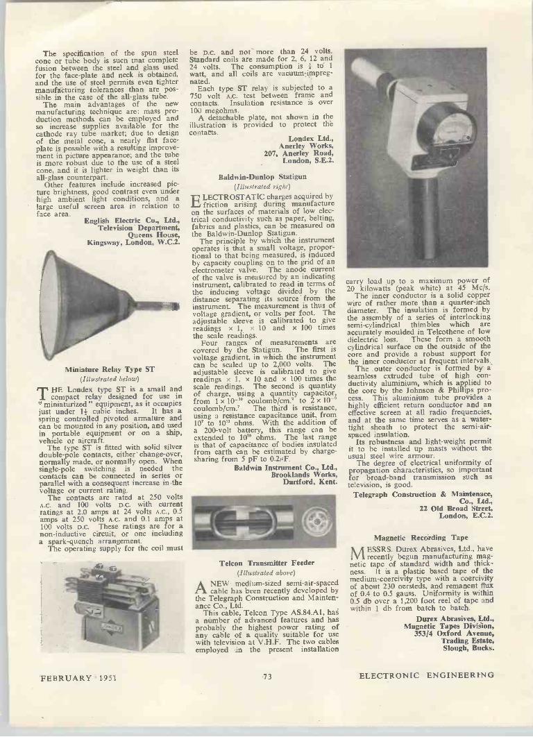
The specification of the spun steelcone or tube body is sucn mat completefusion between the steel and glass usedfor the face -plate and neck is obtained,and the use of steel permits even tightermanufacturing tolerances than are pos-sible in the case of the all -glass tube.
The main advantages of the newmanufacturing technique are: mass pro-duction methods can be employed andso increase supplies available for thecathode ray tube market; due to designof the metal cone, a nearly flat face-plate is possible with a resulting improve-ment in picture appearance; and the tubeis more robust due to the use of a steelcone, and it is lighter in weight than itsall -glass counterpart.
Other features include increased pic-ture brightness, good contrast even underhigh ambient light conditions, and alarge useful screen area in relation toface area.
English Electric Co., Ltd.,Television Department,
Queens House,Kingsway, London, W.C.2.
Miniature Relay Type ST(Illustrated below)
THE Londex type ST is a small andcompact relay designed for use in
" miniaturized " equipment, as it occupiesjust under if cubic inches. It has aspring controlled pivoted armature andcan be mounted in any position, and usedin portable equipment or on a ship,vehicle or aircraft.
The type ST is fitted with solid silverdouble -pole contacts, either change -over,normally made, or normally open. Whensingle -pole switching is needed thecontacts can be connected in series orparallel with a consequent increase in thevoltage or current rating.
The contacts are rated at 250 voltsA.C. and 100 volts D.C. with currentratings at 2.0 amps at 24 volts A.C., 0.5amps at 250 volts A.C. and 0.1 amps at100 volts D.C. These ratings are for anon -inductive circuit, or one includinga spark -quench arrangement.
The operating supply for the coil must
be D.C. and not more than 24 volts.Standard coils are made for 2, 6, 12 and24 volts. The consumption is 1 to 1
watt, and all coils are vacuum -impreg-nated.
Each type ST relay is subjected to a750 volt A.C. test between frame andcontacts. Insulation resistance is over100 megohms.
A detachable plate, not shown in theillustration is provided to protect thecontacts.
Londex Ltd.,Anerley Works,
207, Anerley Road,London, S.E.2.
Baldwin -Dunlop Statigun(Illustrated right)
ELECTROSTATIC charges acquired byfriction arising during manufacture
on the surfaces of materials of low elec-trical conductivity such as paper, belting,fabrics and plastics, can be measured onthe Baldwin -Dunlop Statigun.
The principle by which the instrumentoperates is that a small voltage, propor-tional to that being measured, is inducedby capacity coupling on to the grid of anelectrometer valve. The anode currentof the valve is measured by an indicatinginstrument, calibrated to read in terms ofthe inducing voltage divided by thedistance separating its source from theinstrument. The measurement is thus ofvoltage gradient, or volts per foot. Theadjustable sleeve is calibrated to givereadings x 1, x 10 and x 100 timesthe scale readings.
Four ranges of measurements arecovered by the Statigun. The first isvoltage gradient, in which the instrumentcan be scaled up to 2,000 volts. Theadjustable sleeve is calibrated to givereadings x 1, x 10 and x 100 times thescale readings. The second is quantityof charge, using a quantity capacitor,from 1 x 10-" coulomb/cm' to 2 x 10-°coulomb/cm' The third is resistance,using a resistance capacitance unit, from10' to 10" ohms. With the addition ofa 200 -volt battery, this range can beextended to 10" ohms. The last rangeis that of capacitance of bodies insulatedfrom earth can be estimated by charge -sharing from 5 pF to 0.2µF.
Baldwin Instrument Co., Ltd.,Brooklands Works,
Dartford, Kent.
Telcon Transmitter Feeder(Illustrated above)
ANEW medium-sized semi -air -spacedcable has been recently developed by
the Telegraph Construction and Mainten-ance Co., Ltd.
This cable, Telcon Type AS.84.A1, haga number of advanced features and hasprobably the highest power rating ofany cable of a quality suitable for usewith television at V.H.F. The two cablesemployed in the present installation
carry load up to a maximum power of20 kilowatts (peak white) at 45 Mc/s.
The inner conductor is a solid copperwire of rather more than a quarter -inchdiameter. The insulation is formed bythe assembly of a series of interlockingsemi -cylindrical thimbles which areaccurately moulded in Telcothene of lowdielectric loss. These form a smoothcylindrical surface on the outside of thecore and provide a robust support forthe inner conductor at frequent intervals.
The outer conductor is formed by aseamless extruded tube of high con-ductivity aluminium, which is applied tothe core by the Johnson & Phillips pro-cess. This aluminium tube provides ahighly efficient return conductor and aneffective screen at all radio frequencies,and at the same time serves as a water-tight sheath to protect the semi -air -spaced insulation.
Its robustness and light -weight permitit to be installed up masts without theusual steel wire armour.
The degree of electrical uniformity ofpropagation characteristics, so importantfor broad -band transmission such astelevision, is good.
Telegraph Construction & Maintenace,Co" Ltd.,
22 Old Broad Street,London, E.C.2.
Magnetic Recording TapeMESSRS. Durex Abrasives, Ltd., haverecently begun manufacturing mag-
netic tape of standard width and thick-ness. It is a plastic based tape of themedium-coercivity type with a coercivityof about 230 oersteds, and remanent fluxof 0.4 to 0.5 gauss. Uniformity is within0.5 db over a 1,200 foot reel of tape andwithin 1 db from batch to batch.
Durex Abrasives, Ltd.,Magnetic Tapes Division,
353/4 Oxford Avenue,Trading Estate,Slough, Bucks.
FEBRUARY 1951 7 3 ELECTRONIC ENGINEERING

MODERN PRACTICALRADIO & TELEVISIONThis work covers every phase of Radioand Television Engineering from manyviewpoints and meets a great demand.The author, C. A. Quarrington, A.M.Brit.-I.R.E., has been responsible for trainingRadio and Television Service Engineersand is also well known as a lecturer onRadio and Cathode-ray subjects.
SOME OF THE CONTENTSSound-Waves in Free Space-Electricity-Mag-netism and Inductance-Capacity-Reactance andImpedance-Alternating Current-Tuned Cir-cuit-Principles of the Thermionic Valve-TheSignal Analysed-Detection--Reaction andDamping-H.F. Tetrode and Pentode-High-frequency Amplification-Principles of theSuperheterodyne-Frequency-changing Valves-Design of the Superheterodyne-Practical CoilDesign-Switches and Switching-Low-frequency Amplification-The Output Stage-Output Valves-Loudspeaker-Automatic Vol-ume Control-Tuning Indicators-Inter-StationNoise Suppression-Automatic Tuning-Fre-quency Modulation-Power Pack-Decoupling-Gramophone Pick-up-General Mechanicaland Electrical Considerations-Five CircuitsAnalysed-Aerials, Earths, and Noise Suppres-sion-Car Radio- Principles of Low -powerTransmission-High-Vacuum Cathode-ray Tubeand its Application to Television-Time Base-Television Technique-Television-receiver De-sign-Adjustments and Faults of a TelevisionReceiver-Measuring Instruments-GangingOscillator-Cathode-ray Oscillograph-Voltageand Current Testing-Instability and Motor-boating-Tracing Distortion-Tracing MainsHum-Tracing Background Noise-Valve Testing-Receiver Alignment (Ganging)-Whistles andBreakthrough-Loudspeaker Faults-TestingComponents-Fault-finding Procedure (A Sum-mary)-Local Interference-Workshop Hints-Accumulator Charging and Maintenance-Simple Mathematics, etc.-Abridged TechnicalDictionary.
RADIO CIRCUITS AND DATAA wide selection of typical and basiccircuits with formulae and data, are alsoincluded, together with a number ofManufacturers' and complete basiccircuits showing the latest trends andpractices, apart from a comprehensiverange of unit circuits.
THE ILLUSTRATIONS
"Modern Practical Radio and Television"is profusely illustrated. It contains 16full -page plates, over 400 diagrams inthe text and 7 large folding insets. Eachillustration has been specially selectedfor its practical utility.
SEND FOR FREE PARTICULARS
To The Caxton Publishing Co., Ltd.,171, Morley Hall, St. George Street,Hanover Square, London, W.I.Please send me, free of charge particularsof " Modern Practical Radio and Tele-vision."
NameSend this form in unsealed envelope (Id. stamp)
Address
R.T.6
BOOK REVIEWSRadio and Television Mathematics
By Bernhard Fischer. 484 pp. 1st Edition.Macmillan and Co.. Ltd. 1949. Price 45s.
THIS book is divided into four parts:part one, occupying the first 350 pages,
consists entirely of problems and solu-tions, over 400, grouped under 13 subjectsectional headings; part two sets an addi-tional 300 questions, proportionatelydistributed under the same headings, towhich numerical answers are given in theback of the book; part three is entitled"Some Important Tools of Radio Mathe-matics," and is in four short sections on,Powers of 10, The Slide Rule, The j -Operator and Polar Vectors; part fouris a list of formulae and tables uponwhich the solution to problems is based.The book contains over 160 illustrations,most of which are in part one.
To epitomize the approach employed,quoting from the author's preface, " theauthor has become increasingly aware ofthe great educational value of numericalanalysis as compared with literal analysis. . . thus 2 + 3 +5 will read 10 in thesubsequent step of a calculation, whereas
+ +I-, will remain R+ Re + r in thenext step, and will accumulate into atangle of letters which appears monstrousto the beginner." However, a great manyof the problems are solved by simplesubstitution in formulae taken frompart 4.
The book is intended to have a prac-tical slant, but there are some ratherdangerous implications from this view-point, e.g., that a capacitor of specifiedmaximum working voltage may be usedacross an A.C. line whose crest voltageonly just comes within this maximum.As frequently happens in mathematicalsubjects, there are several errors thatcould well be typographical, however,where these are in formulae there is thegreater danger of leading a student toa wrong solution, especially as the bookappears to encourage substitution informulae, and gives little exercise intransposition. For the conversion oftemperatures, the correct formula,C =5/9(F -32) is followed by F=9/5(C +32). A serious error appears in theformulae for delta -star and star -deltatransformation. The former are correctlygiven, but the latter are dimensionallywrong. The author may have erred inalgebraic transposition - the expertmathematician is not exempt from thepossibility of such errors, but a simpleprinciple that will often assist in detect-ing them is the rule of dimension. It isfelt that this could have been included inpart three of the book to advantage.
The book should prove useful tolecturers as a source of examples, but itmust be remembered that those basedupon the American Wire Gauge given inthe book will not be strictly practical forBritish students.
N. H. CROWHURST
" Antenna Theory and Design "Vols. I and II
By H. Paul Williams. 142 and 522 pp. Pub-lished by Sir Isaac Pitman and Sons, Ltd., Lon-don. 1950. Price 21s. (Vo!. I) and 63s. (Vol.
THESE two volumes constitute a mostcomprehensive treatment of the theory
and practice of aerial design.Volume I deals with the theoretical
aspects of the subject, starting with thefundamental laws of electromagnetismand Maxwell's equations and then pro-ceeding to the radiation characteristics ofdoublets, dipoles and travelling -waveaerials. The final chapter discusses theuse of the Poynting vector for calculatingthe radiated power and gives a theoreticalanalysis of the radiation from dipoleaerials in terms of equivalent trans-mission lines, cylinders, cones andspheres. Thus it may be said that Vol. Ibridges the gap between the fundamentallaws of electromagnetism and the basictheory needed by the designer of aerials.
Vol. II covers the more practical aspectof aerial design and is complete in itself.This is the volume to which an engineer,who has a specific aerial design problemto solve, will turn with a fair assurancethat he will find at least the outline of asolution and probably references tosources of additional information. Thescope of Vol. II is very wide, rangingfrom the aerials of the high -power, 18,750metres wavelength, transmitter GBR atthe Rugby Radio Station of the GeneralPost Office, to aerials suitable for wave-lengths of the order of 3 cm for radar.
The discussion of long and medium -wave aerials for broadcasting is particu-larly well done and it would appear thatthis is a field in which the author hashad considerable personal experience. Thetreatment of short and ultra -short waveaerials is also adequate and is illustratedby a considerable amount of measureddata.
A useful feature is the large numberof design curves which are given, theseare mainly drawn with logarithmic scalesso facilitating calculations. For examplethe design of a rhombic aerial can becarried through using only the designcurves, tracing paper and pencil, withoutemploying a slide rule or tables oflogarithms.
The design of microwave aerials suchas parabolic mirrors, corner reflectors,horn radiators and slot aerials is dis-cussed in some detail. However, notableomissions from this section of the workare the delay -lens, path -length lens andartificial dielectric lens aerials of Koch.The treatment of waveguide feeders andradar scanning aerials is also somewhatincomplete.
A considerable amount of informationis given on the propagation characteris-tics of long, medium, short, ultra -shortand micro -waves, including the noiselevels to be expected in receiving aerials.This section of the book is, in thereviewer's opinion, more detailed than is
ELECTRONIC ENGINEERING 7 4 FEBRUARY 1951

justified in a treatise on aerials, particu-larly since most of the information is available elsewhere. It is suggested that some of the space allocated to propaga-tion might have been more usefully employed in discussing the measurement of the polar diagram, gain and im-pedance characteristics of aerials—sub-jects not fully covered in this book.
In spite of the minor limitations noted above, "Antenna Theory and Design" can be confidently recommended to all engineers concerned with aerial design, no matter in what part of the frequency spectrum.
W. J. BRAY
Invention and Innovation in the Radio Industry
By W. Rupert Maclaurin. Pp. 304 + xii. Mac-millan. New York. 1949. Price 306.
THIS is an unusual book which should be read by all concerned with radio
and its allied subjects. At the same time stimulating and depressing, it sets out to record the histories and inventions of the great names in radio—Marconi, Fleming, de Forest, Armstrong, etc., and of the commercial giants which grew up and around them, the Marconi com-panies, R.C.A., General Electric, Westinghouse, A.T. & T., and so on. It recounts the story of the "perennial gale of competition" and of the endless patent litigation which followed each major advance in the art, and gives an integrated view of how the present com-plex structure of radio big business has evolved. Many books must have been written on the scientific and technical aspects of radio progress, but this is perhaps the first that has examined the economic factors which influence tech-nological discovery to a greater extent than is sometimes realized. The volume is one of a series—the
Massachusetts Institute of Technology Studies in Innovation—and is written by an economist, with a scientific back-ground, who is well qualified to lead the way through such a particularly involved topic. Engineers, commercial men and the general public alike will find this book performs a valuable service in bringing out the relations between, and the inter-dependence of, commerce and science in the field of radio. The treat-ment is substantially non-technical but the text is the more easily understood by those with a working knowledge of radio, and a short appendix outlines the technical elements of modern radio communication systems for lay reader. A few chapter headings: The Impact
of New Scientific Advances on Estab-lished Industry; The Process of Inven-tion and Innovation—Marconi and the Wireless Telegraph: 1896-1920; The Role of the Large Electrical Firms in Wire-less: 1912-1921; The Struggle over Patents: 1921-1928; The Perennial Gale of Competition: 1928-1941, and The Rise of Industrial Research—Radio: 1900-1941 illustrate the general scope of the book, but cannot tell of the wealth of fact and detail that is present in its pages. The names of radio organisations which are almost household names on both sides of the Atlantic constantly recur and the
eternal struggle for power, the com-petitive frenzy, the legal fights and the commercial manoeuvring of the Ameri-can radio industry during the last half-century are detailed and analysed with keen insight. It presents some amazing stories—of the court case on valves which lasted for 18 years, the mush-room growth and almost equally rapid dissolution of many firms, the ever shift-ing sands of commercial politics, and gives the inside story of the colossus that American radio has grown to be.
Altogether, this is a book not to be missed by all radio people, whether commercial or technical, who sometimes stop to think of the philosophical and economic aspects of their job and wonder what the future holds. It should be bought and used, not only as highly interesting general reading, but also as a well-informed text on an unusual facet of the radio game.
E. D. HART
Electronics Manual for Radio Engineers
Edited by Vin Zeluff and John Markus 879 pp. McGraw-Hill Book Company, Inc., New York, and the McGraw-Hill Publishing Co., Ltd., London. 1949. Price 57s. net.
THIS manual contains 289 of the more important articles which appeared in
the American journal "Electronics" dur-ing the period 1940 to 1948, thus cover-ing the War years when activity in research and development in the field of electronics was at its maximum. The articles are collected in 16 chapters, each covering a separate phase of electronics, viz., Antennas, Audio Equipment and Techniques, Circuit Theory, Components, p.c. Amplifiers, Filters, Ionosphere (including some articles on tropospheric propagation), Measuring Equipment and Techniques, Microwaves, Power Supplies, Production (i.e., equipment and tech-niques for the control of industrial pro-cesses), Receivers, Television, Trans-mission Lines, Transmitters and Tubes. The location of a desired article is straightforward since both an author and a subject index are included, the latter being extensively cross-indexed.
In general the emphasis is on the type of practical information needed by an engineer with a design problem to solve in a minimum of time, for example there are numerous charts, design curves, nomograms and tables of data for the rapid solution of circuit and propagation problems. A large proportion of the circuit diagrams give component values, most of the constructional diagrams are dimensioned and the performance of the circuits or components described is, in nearly all cases, illustrated by measured characteristics. Although the book will be mainly of value to engineers, it will also be of assistance to research workers in electronics by providing them with ready-made solutions to many of their circuit problems, thus freeing them for more fundamental work. The "Electronics Manual for Radio
Engineers" is particularly valuable for the broad survey it provides of the most recently developed techniques in elec-tronics, much of the information presented is not available even in the most recently published text-books in
CHAPMAN & HALL
Just out
CONDUCTIMETRIC ANALYSIS AT
RADIO FREQUENCY A New Technique for Titration
by
G. G. Blake F.INST.P., M.I.E.E.
Foreword by o. U. VONWILLER
(Emeritus Professor of Physics, Sydney University)
109 pages 40 figures ¡Ss. net
Ready this month
TIME BASES by
O. S. Puckle M.B.E., M.I.E.E. Second Edition
Completely Revised and Enlarged
416 pages 257 figures 30s. net
37 ESSEX STREET, LONDON, W.C.2
ELECTROPHYSIOLOGICAL
TECHNIQUE
by C. J. DICKINSON, B.A., B.Sc. (Magdalen College, Oxford)
Demy 8vo. 140 pp. Price I2s. 6d. Postage 6d. The author desceibes the use of electronic methods as applied to re-search in Neurophysiology. Chapters are devoted to modern techniques for time marking, stimulating pro-duction and recording of mechanical movement.
VOLTAGE STABILIZERS
by F. A. BENSON, M.Eng, A.M.I.E.E., M.I.R.E. (University of Sheffield) Demy 8vo. 125 pp. Price I2s. 6d. Postage 6d. This monograph describes the various devices empioying magnetically satur-ated elements in glow-discharge tube circuits and therm ionic valve arrange-ments for voltage stabilization. A comprehensive bibliography is in-cluded.
PUBLISHED BY
Electronic Engineering i 28, ESSEX STREET, STRAND,
LONDON, W.C.2
FEBRUARY 1951 75 ELECTRONIC ENGINEERING

this field. This information includes descriptions of methods, equipments and techniques developed in the research laboratories of commercial organizations, accounts of work done during the War under Government contract for the American Office of Scientific Research and Development and which has hitherto only been available through official documents and reports, together with some account of work in electronics carried out in the research laboratories of universities and colleges. Particularly important from the industrial standpoint is the chapter on the application of electronics to the control of manufactur-ing and mass production processes, this being a field in which the Americans have made notable contributions.
In addition to the numerous practical articles there are several theoretical analyses, relating for example to signal-to-noise and bandwidth considerations in communication systems, the design of cathode followers, filters, rectifier type power supply systems and microwave components. However, the main value of the book will undoubtedly be for its treatment of the practical aspects of the subject, the theoretical side being in general subjugated to the practical.
It would of course be unreasonable to expect a uniformly high standard of clarity, accuracy and originality through-out a book compiled from so many diverse sources, nevertheless the general standard is high for a manual of this type and is a tribute to the thoroughness of the editing.
Perhaps one of the main advantages of having the material presented in the form adopted is not only that articles on similar subjects are collected together for easy reference, but it is possible to read a given article from beginning to end without having to search among the advertisement pages for its continuation, as was the case when the articles were originally published in periodical form. This manual is thoroughly recoin-
mended, as it will undoubtedly save its cost in many electronics research and development laboratorieg by reducing the man-hours spent in searching for information, and in minimizing the un-necessary duplication of work already carried out on the other side of the Atlantic.
W. J. BRAY
Elektronenoptik, Vol. I Dr. Alexander A. Rusterholr. 249 pp. Grund-Mige der theoretischen Elektronenoptik. Birk-Miuser, Basel. 1950. Price 65s. (In German.)
THE new science of electron optics was well documented from its very
inception. The first comprehensive treatise, by Brüche and Scherzer, appeared in 1934, only eight years after Busch had formed the magic union of the two words " electron" and "lens," which until that time appeared to be worlds apart. This was followed by the textbooks of Maloff and Epstein, Picht, Myers, Klemperer, Cosslett, Zworykin and collaborators, not to mention the numerous works on such special branches as cathode ray tubes and electron micro-scopes. The new treatise by Dr. Alexander A. Rusterholz, Engineer in the Electron Valve Works of the Brown, Boyen i Co., Baden, Switzerland, promises to continue the tradition on an even
larger scale. The first volume, which has just appeared, is a painstakingly com-plete re-statement of the classical parts of geometrical electron optics, in plane or rotationally symmetrical fields, with-out space charge. It is correct and com-plete, and the student who does not want to go beyond what is already well known could not find a better book. But it has also its limitations, which it shares with many other textbooks primarily written for engineers, who are presented with a living and growing branch of engineering in a frozen form, and might be led to believe that all they would have to do in practice will be the appli-cation of known formulae. This is particularly important in electron optics, which had an unusually rapid develop-ment, and has come up very early against limitations, which can be over-come, if at all, only by unorthodox means. This is a situation quite different from that in light optics, which, after 300 years. is still progressing steadily by more and more complicated applications of the same orthodox principles, aided only by new materials. But electron optics has only one medium, the electro-magnetic field in vacuo, and though it is very easy to produce a " first order" lens, we know that we cannot, by ortho-dox means, ever produced a corrected lens. Hence it would be desirable, if a large textbook, like the present, would from the start present the reader with a wider view, and more general methods. It may be, however, too early to pro-nounce a judgment before seeing the second volume, in which the author promises to treat also non-stationary fields and space charges. In the reviewer's opinion, to be satisfactory it ought to comprise also non-symmetrical systems and at least the elements of electron wave optics. The limited field which forms the
subject of this first volume is treated with great thoroughness, as may be judged from its chapters: 1. The elec-tron in electric and magnetic fields; 2. The electron-optical refractive index; 3. Rotationally symmetric fields; 4. Electron trajectories in rotationally sym-metrical fields; 5. Electric lenses; 6. Magnetic and electro-magnetic lenses; 7. The aberrations; 8. Two-dimensional fields. Electron prisms; and 9. Electron mirrors. There are ample references, and a subject index. The high price of the book will prob-
ably restrict the circulation in this country, as far as the general and individual reader is concerned, but it may be recommended to university and laboratory libraries.
D. GABOR
Microwave Measurements By H. M. Barlow and A. L. Cullen. 399 pp. Constable. 1950. Price 30s.
THE only text-books on measurements at centimetric wavelengths so far
published are relatively expensive American works and the appearance of this volume will be welcomed by micro-wave workers in this country. Micro-wave measurements involve a more detailed examination of electromagnetic fields than is the case at longer wave-lengths and so the techniques are very different. In the first three chapters an outline of the theory of waveguides and
cavity resonators is given: it would be impossible to discuss these without referençe to Maxwell's equations, but the non-mathematical reader need not be afraid of finding the treatment beyond him. The introduction of the analogy with transmission lines is introduced at an early stage and a detailed discussion of the circle diagram follows. The many examples of calculations which follow later in the book bring out very clearly the advantages to be obtained from use of the circle diagram. The first measurements to be con-
sidered are those of wavelength and frequency, and as elsewhere in this book the emphasis is upon general principles rather than descriptions of particular pieces of apparatus, for which ample references are given. The cavity resona-tor method is the most fully described, but an omission which might well be rectified in a future edition is the use of this method for the determination of the velocity of electromagnetic waves. One of the commonest measurements
required is that of a standing wave ratio and it is fitting that one of the longest chapters should be devoted to this. A more exhaustive analysis of the effect of the probe on the accuracy of measurement than has hitherto been available is given and will be of value to anyone who habitually uses a standing wave gear. Much useful information on the mechanical tolerances required in order to achieve a given standard of accuracy is given in the section on constructional methods. Standing wave measurements are usually the prelimi-nary to the matching of a transmission system and this is treated in the follow-ing chapter. The bulk of the discussion, much of which is new, is concerned with the general case and a minor criti-cism is that there is no detailed example of the application to a particular prob-lem. The question of the bandwidth of the match, a most important one in practice, merits a rather fuller treatment than is given. The remaining chapters deal with
attenuation, power, the properties of materials and the measurements arising with receivers, transmitters and aerials. The section on attenuators is particularly interesting for the circuit analogy explaining the apparent paradox. that the power in an attenuator is transmitted by an attenuated mode. A very pleasing feature of this book
is the large number of experimental values and curves used to illustrate the measurements described. The authors are to be congratulated
on producing a book which may profit-ably be read by anyone working in this field.
J. BROWN
Electrical Engineers' Companion 268 po. 2nd Edition. London Electric Wire Ca. and Smiths, Ltd. 1950. Price 5s.
THIS attractive little pocket book of useful electrical data has been
brought up to date in this edition, and arranged and indexed for easy reference to any specific subject. Modern data has been collated relating
to bare and insulated wires and cables from many sources, including the B.S.I., I.E.E., and E.R.A.
ELECTRONIC ENGINEERING 76 FEBRUARY 1951

Notes from the Industry
The Physical Society's 35th Annual Exhibition of Scientific Instruments and Apparatus will be held from Friday, 6, to Wednesday, 11 April, 1951, excluding Sunday.
This year both the Royal College of Science Main Building, Imperial Insti-tute Road. and the Huxley Building, Exhibition Road (opposite Science Museum) will be used. On Friday morning the Exhibition will be open for members of the Society and the Press only, and all tickets will be valid for entry into both buildings.
This Exhibition takes place before the opening of the Festival of Britain, but physicists from abroad who intend to visit the latter may like to make arrange-ments to come to England earlier as the Exhibition affords one of the most important displays of scientific achieve-ment which is held in Great Britain, and is unique in showing side by side the work of academic scientists, commercial instrument makers and research workers in Government and other laboratories. It will also provide a convenient opportu-nity for conversations and contacts with technical representatives of British firms and associations.
Discourses will be delivered by eminent scientists on four days of the Exhibition, and the prize-winning models of the Society's Craftsmanship and Draughtsmanship Competition will be on show. This competition, which is open to apprentices and others under the age Of 22 years, is organized to stimulate the interest of young craftsmen and draughts-men. in industrial firms. technical col-leges and Government departments. A Handbook of the Exhibition, con-
taining full descriptions of all exhibits will be obtainable in early March from the Physical Society at I, Lowther Gardens. Prince Consort Road, London, S.W.7.
Obituary. Mr. Percy Good, C.B.E., M.I.E.E.. died on December 2. He was a director of the British Standards Insti-tution, and had been connected with the Institution for 37 years. Mr. Good was also a past president of the Institution of Electrical Engineers.
B.S.I. New Director and Secretary. Mr. H. A. R. Binney, C.B.. has been appointed director and secretary in suc-cession to the late Mr. Percy Good, C.B.E.
Lectures on Ultrasonics have been arranged at the Polytechnic, 307-311 Regent Street. London, W.1, commenc-ing March 2. There will be four lectures, and the fee for the course is 10s. The syllabus covers fundamentals, generation and reception of ultrasonic waves, and applications of ultrasonics. Full details can be obtained from the Polytechnic.
New R.A.M.A.C. Secretary General. Mr. E. Fost has been appointed Secretary General of R.A.M.A.C. in succession to Mr. J. Connell, who is now retiring from the post, which he has held since the formation of the Association. R.A.M.A.C. (Radio Marine Associated Companies) is a world organization of companies operating marine radio ser-vices. The resources of the member companies are co-ordinated to further the development of ships' radio equipment and aids to navigation. Mr. Fost has been associated with
marine radio for 25 years. His office will be at the R.A.M.A.C. headquarters, 109 Eaton Square, London, W.I.
New Chairman for Standard Tele-phones and Cables, Ltd. Sir Thomas G. Spencer, M.1.E.E., managing director of Standard Telephones and Cables, Ltd., has been elected chairman of the board of directors of the company. He succeeds the late Sir Frank Gill, K.C.M.G., 0.B.E., who died on October 25, 1950.
With Standard Telephones and Cables, Ltd. (formerly the Western Electric Company, Ltd.) since 1907, Sir Thomas was called upon to take charge of the company in 1932, and will continue in the capacity of managing director in addition to holding the office of chair-man.
The R.C.A. Manual RC-16. The new R.C.A. Receiving Tube M'anual, RC-16, which incorporates many new features reflecting new developments in elec-tronics. has been completely revised, expanded, and brought up to date. Con-taining over 300 pages, it is 25 per cent larger than the previous RC-15 edition which it supersedes. The same complete coverage of tech-
nical data contained in previous editions, ranging from elementary theory to descriptions of latest receiving-tube applications, has been continued and enlarged in the new RC-16. Detailed technical information is provided on more than 460 R.C.A. receiving tubes and cathode ray tubes including many dis-continued types. The section on valve and circuit theory has been expanded and includes formulae and examples for calculation of power output, load resis-tance and distortion for several classes of amplifier service as well as cathode follower design information. Television coverage includes C.R.T. installation data and handling information.
Orders for single copies of the RC-16 Tube Manual may be placed with R.C.A. Photophone, Ltd., 36 Woodstock Grove, W.12. The price of the manual is 5s. 6d. post free.
American Order. Messrs. Tenaplas, Ltd., have recently received orders covering a total of over 950 miles (five million feet) of polythene-covered and P.V.C.-covered twin flat wire from a firm in New York. The wire is to be used for electrical purposes.
PUBLICATIONS RECEIVED
HELVIN LIST B.209 describes the applications of this special type of P.V.C. made by Heller-mann Electric, Ltd., Tinsley Lane, Crawley. Sussex, which include a wide range of articles for the radio, electronic, automobile and aircraft industries either in the form of mouldings or by other special processes described in this booklet.
SCIAKY PMCO2ST THE THREE PH4SE MODU WAVE WELDER concerns a new resistance welder for spot welding aluminium, etc., developed by Sciaky Bros., 4915 West 67th Street, Chicago 38, Illinois, U.S.A., from whom a brochure may be obtained.
EDISWAN MICROFILM READERS is a brochure describing these instruments, which pro. vide high quality reproduction from all normal 35 mm. microfilm frame with easy manipulation, and do not necessitate a dark room. Full details from the Edison Swan Electric Co., Ltd., 155 Charing Cross Road, London, W.C.2.
G.B. 16 MM. ENTERTAINMENT FILM CATALOGUE includes a section on industrial hlms, which covers steel, optical glass, the manu-facture of plastics, etc. Civics and social welfare are also subjects of interest. It is obtainable from G.B. Equipments, Ltd., Mortimer House, 37-41 Mortimer Street, London, W.I.
BURGESS MICRO-SWITCHES CATALOGUE NO. 50 is a brochure describing the types made by Burgess Products Co., Ltd., Micro-Switch Disision, Sapeote. Leics., and includes schematic diagrams of the switches.
" FLUON" POLYTETRAFLUOROETHYLENE is a booklet concerned with the manufacture of this type of plastic. It has previously been developed commercially in the U.S.A., and is now made in Britain by Imperial Chemical Indus-tries, Ltd.. Gloucester House, 149 Park Lane, London, W.I.
ELECTRICAL ENGINEERING ABSTRACTS. DECEMBER 1950. This booklet is Section B of **Science Abstracts " which are edited and issued monthly by the Institution of Electrical Engineers, Savoy Place, London, w.Ç.2.
EKCO CAR RADIO is a catalogue of the types of car radio made by Ekco's. It gives full tech-nical details of their parts, etc., and can be obtained from E. K. Cole, Ltd., Ekco Works, Southend-on-Sea, Essex.
WIGGIN NICKEL ALLOYS NO. 328 features various types of furnace equipment, and the heat. resisting uses of high nickel alloys. Other items of general interest are uses of these materials in glass blowing, modern engine fuel lines, food processing, hospital equipment, and chemical plant. Henry Wiggin & Co., Ltd., Wiggin Street. Birmingham 16.
" JUAN DE LA CIERVA" FOUNDATION FOR TECHNICAL RESENRCH—Its Organiza-tion and Development. This most attractive and beautifully illustrated brochure describes this Spanish technical Foundation. It lays out its purpose, and describes its centres and institutes which cover a wide range such as scientific apparatus, fuel research, welding, iron and steel, electronics and rationalization. Institute of Electronics, Rios Rosas 54, Madrid, Spain.
EASIBINEI FOLDERS
Readers are reminded that a few of the old size Easibind Folders are still assit-able for binding their 1950 issues of "ELECTRONIC ENGINEERING", and can he obtained from the Circu'ation Department. price 12s. 6d. postage 6d. Easibind Folders for the new size journal are also available at the same
price.
1950 INDEX
The 1950 Index, Volume 22. is still available. Copies may be obtained with-
out charge and post free, on application to the Circulation Department or this
Journal.
FEBRUARY 1951 77 ELECTRONIC ENGINEERING
MEETINGS THIS MONTH
INSTITUTION OF ELECTRICAL ENGINEERS
All London meetings, unless otherwise stated. are held at the institution of Electrical Engineers,
Savoy Place, London, W.C.2. Date: February I. Time: 5.30 p.m. Lecture: Standardization and Simplification in the
Electrical Industry. By: J. T. Moore, B.Sc. Lecture: An Organization for Internal Standardi-
zation in a Large Manufacturing Company. By: P. J. Daglish, B.Sc. Date: February 14. Time: 6.30 p.m. Held at: The Central Hall, Westminster, SW. I. Faraday Lecture: Lamps and Lighting--A Record
of Industrial Research. By: L. J. Davies, M.A., B.Sc.
Radio Section Date: February 7. Time: 5.30 p.m. Lecture: Radio-Valve Life Testing. By: R. Brewer. Date: February 19. Time: 5.30 p.m. Discussion: Is there an Optimum Speed for a Gramophone Record?
Opened by: G. F. Dutton, Ph.D., B.Sc.(Eng.).
Measurements Section Date: February 13. Time: 5.30 p.m. Lecture: The Inductor Compass. By: A. Hine, B.Se.Tech. Date: February 27. Time: 5.30 p.m. Discussion: Electrical Measurement by Thermal
Effects. Opened by: Professor J. Greig, M.Sc., Ph.D ,
L. G. A. Sims, D.Sc., Ph.D., and J. G. Freeman, M.A., Ph.D.
Utilization Section Date: February 15. Time: 5.30 p.m. Lecture: The Dimming of Low-Pressure Uscharge Lamps.
By: C. E. Williams, B.Sc.
Informal Meeting Date: February 12. Time: 5.30 p.m. Discussion: Inventor. Engineer, and Manager. Opened by: P. P. Eckersley.
Supply Section Date: February 21. Time: 5.30 p.m. Lecture : Transient Theory of Synchronous Generators Connected to Power Systems.
By: B. Adkins, M.A.
INSTITUTION OF POST OFFICE ELECTRICAL ENGINEERS
Date: February 6. Time: 5 p.m. Held at: Institution of Electrical Engineers, Savoy
Place, W.C.2. Lecture: Some Aspects of Electronic Circuit
Design. By: S. W. Broadhurst and A. W. M. Coombes, Ph.D.
Informal Meeting
Date: February 21. Time: 5 p.m. Held at: Conference Room, 4th Floor, Waterloo
Bridge House, S.E.1. Lecture: Public Speaking. By: A. K. Robinson, M.I.E.E.
TELEVISION SOCIETY Date: February 1. Time . 7 Held at: Cinema Exhibitors'
Shaftesbury Avenue, W.C.2. Lecture: On the Technique of
viewing. By: Leslie Mitchell. Date: February 23. Time: 7 Held at: The Cinema Exhibitors'
Shaftesbury Avenue, W.C.2. Lecture: Television from Calais Channel Broadcast.
By: W. D. Richardson and W.
Engineering Group Date: February 8. Time: 7 p.m. Held at: The Cinema Exhibitors' Association, 164
Shaftesbury Avenue, W.C.2. Lecture: The First British Multi-Channel Receiver. By: W. D. Asbury, K. M. B. Wright and W. M.
Lloyd, B.Sc.
p.m. Association, 164
Television Inter-
p.m. Association, 164
-The First Cross-
N. Anderson.
SECRETARIES OF ASSOCIATIONS
INSTITUTION OF ELECTRICAL ENGINEERS
The Secretary, Institution of Electrical Engineers, Savoy Place, W.C.2.
Cambridge Radio Group G. E. Middleton, M.A. University En-
gineering Laboratory, Cambridge.
North-Eastern Radio and Measurements Group
G. A. Kysh (Asst. Sec.), Carliol House, Newcastle-on-Tyne, I.
North-Western Radio Group A. L. Green (Asst. Sec.), 244 Brantingham Road, Chorlton-cum-Hardy, Man-chester, 21.
South Midland Radio Grout; W. H. Brent, B.Sc. Regional Director's
Office. Midlands Region (G.P.O.), Civic House, Great Charles Street, Birming-ham, 3.
BRITISH INSTITUTION OF RADIO ENGINEERS
The General Secretary, 9 Bedford Square, London, W.C.I.
West Midlands Section R. A. Lampitt, A.M.Brit.I.R.E., 20
Northfield Grove, Merry Hill, Wolver-hampton.
INC. RADIO SOCIETY OF GREAT BRITAIN
General Secretary, New Ruskin House. Little Russell Street, W.C.I.
BRITISH SOUND RECORDING ASSOCIATION
Richard W. Lowden, " Wayford," Napoleon Avenue, Farnborough, Hants.
TELEVISION SOCIETY Lecture Secretary: T. M. Lance, 180 Bromley Road, Beckenham, Kent.
Engineering Group G. T. Clack, 10 Tantallon Road, Balham, London, S.W.12.
RADAR ASSOCIATION The Secretary, 83 Portland Place, Lon-
don, W.I.
INSTITUTION OF POST OFFICE ELECTRICAL
ENGINEERS W. H. Fox, A.M.I.E.E., Engineer-in-
Chief's Office (T. P. Branch), Alder House, E.C.1.
INSTITUTION OF ELEC-TRONICS
Lecture Sec.: W. Summer, 31 Beech Road, Bournville, Birmingham, 30.
North-West Branch W. Birtwistle, 17 Blackwater Street, Rochdale, Lancs.
SOCIETY OF RELAY ENGINEERS
T. H. Hall, M.Brit.I.R.E., 23 Dalkeith Place, Kettering, Northants.
SOCIETY OF INSTRUMENT TECHNOLOGY
L. B. Lambert, 55 Tudor Gardens, London, W.3.
SOCIETY OF INSTRUMENT TECHNOLOGY
Date: February 27. Time: 6.30 p.m. Held at: Manson House, Portland Place, London, W.I.
Lecture: The Measurement of Surface Tempera-ture.
By: Dr. R. C. Parker.
BRITISH INSTITUTION OF RADIO ENGINEERS London Section
Date: February 21. Time: 6.30 p.m. Held at: London School of Hygiene and Tropical
Medicine, Keppel Street, London, W.C.1. Lecture: Electronics and Air Transport. By: C. H. Jackson, B.Sc., A.F.R.Ae.S., A.M.I.Mech.E.
Scottish Section Date: February 1. Time: 6.45 p.m. Held in: Edinburgh. Lecture: Multi-Station V.H.F. Communication Systems using F.M.
By: W. P. Cole, B.Sc., and E. G. Hamer, B.Sc.
Merseyside Section Date: February 7. Time: 7 p.m. Held at: Electricity Service Centre, Whitechapel,
Liverpool. Lecture: A Transmitter for an Experimental 8-Channel Wire-Broadcasting System.
By: R. G. Kitchenn, B.Sc.(Eng.).
South Midlands Section Date: February 14. Time: 7.15 p.m. Held at: East Midlands Electricity Board,
Coventry. Lecture: A Survey of Television Development and its Problems.
By: H. J. Barton-Chapple, B.Sc.
North Eastern Section Date: February 14. Time: 6 p.m. Held at: Neville Hall, Westage Road, New-
castle-on-Tyne. Lecture: The Use of Foster's Theorem in Circuit
Design. By: E. Williams, Ph.D.
West Midlands Section Date: February 28. Time: 7 p.m. Held at: Wolverhampton and Staffs. Technical
College, Wulfruna Road, Wolverhampton. Lecture. Power Rectifiers. By: J. C. Milne.
BRITISH SOUND RECORDING ASSOCIATION
Date: February 16. Time: 7 p.m. Held at: Royal Society of Arts, John Adam
Street, London, W.C.2. Lecture : The Application of Elementary Mechanics to Sound Recording.
By: J. F. Doust.
INSTITUTION OF ELECTRONICS Midlands Branch
Date: February 6. Time: 7 p.m. Held at: Warwick Room, Imperial Hotel, Temple
Street, Birmingham 2. Lecture: Electronic Aids in Engineering, Research and Development.
By: J. R. Cornelius.
RADAR ASSOCIATION Date: February 6. Time: 7.30 p.m. Held at: The ' Albert Tavern, Victoria Street. London, S.W.I.
Monthly Meeting.
East Anglian Branch Date: February 24. Held at: Lamb Inn, Norwich. Monthly Meeting.
INC. RADIO SOCIETY OF GREAT BRITAIN
Date: February 23. Time: 6.30 p.m. Held at: Institution of Electrical Engineers, Savoy
Place, W.C.2. Lecture: Post-War Developments in Television. By: H. A. M. Clark, B.Sc.(Eng.), A.M.I.E.E.
ELECTRONIC ENGINEERING 78 FEBRUARY 1951

By request At the request of many of our constructor
friends, we give here full details of the famous range of Stentorian chassis.
Flux I Cone Density
Type die. (Gauss)
* S.2.57 24.-* S.3.57 3,1-S.507 5"
*S.610 6" 5.707 7" S.810 8" S.9I2 9" 5.1012 10" S.I2135 12" S.1814 18"
1
7,000 7,000 7,000 0,000 7,000 0,000 2,000 2,000 3,500 4,000
Pole dia.
Gap length
.375" .033"
.625" .035"
.75"
.75" .040" 1" .043"
.043" I" .043" I" .043" 1.5" .050" 2.5" .0625"
1
Flux face
.093"
.125"
.125"
.125
.187"
.187"
.187"
.187"
.25"
.312"
Total flux
Speech coil
Impedance (ohms)
Handling Capacity (watts)
Prices
With Without Trans. Trans.
5,285 11,500 14,000 20,000 27,650 39,500 47,400 47,400 106,000 227,000
3 3 3 3 3 3 3 3
15 12
.3 2 2.5 3 3.5 5 7 10 15 30
I 5 0 I 8 6 I 10 6 I 13 6 I 19 0 2 II 0 8 8 0
15 6 16 6 17 6 110 110 1 4 0 1 9 6 1 17 6 7 7 0
24 0 0
Further details of these speakers and of the famous Concentric-Duplex models gladly sent on request.
* All chassis material is of Maack 3 except 5.2.57, 5.3.57 and 5.610 which are of
Drawn Steel.
le/ WU ri LOUDSPEAKER CHASSIS ll •
WHITELEY 'ELECTRICAL RADIO CO. L1TD. • MANSFIELD • NOTTS.
?HERE is a Delaron grade to suit any desired electrical insulation requirement and to meet all official speci-fications. Delaron can be sawn, drilled, punched, shaped and fabricated—is available in thicknesses from is"—in two colours, black and brown, matt or glossy finish—and in various board sizes. Please write for details and samples
An illustration of
part of the navi-gational equip-
ment of an aircraft, showing Delaron
insulation mount-ing strips and terminal panels
wired in position.
41An illustration of the valve chassis of the amplifier unit used in an electronic pilot indicator. !Group boards made from Pil3K IDelaror. are 'shown separately.
DELARON LAMINATED PLASTIC BOARD
THOMAS DE LA RUE & CO., LTD. (Plastics Division) IMPERIAL HOUSE, REGENT STREET, LONDON, W.I
21 FEBRUARY 1 951 ELECTRONIC ENGINEERING
Backed by 50 years manufacturing experience Connollys
range of winding wires are unsurpassed for quality.
Whether the insulation
consists of Enamel, Cotton,
Silk or Rayon, strict tech-
nical control over every
stage of manufacture—plus
the priceless fund of ex-
perience—ensures uni-
formity of quality of the
highest degree.
Send for free leaflets
describing these products
FOR ALL TYPES OF
WINDING WIRES
CONNOLLYS (BLACKLEY) LTD. MANCHESTER 9 CHEetham Hill 1801
London Office : 34 Norfolk Street, London, W.C.2 TEMple Bar 5506
Birmingham Office : 19 Bent Avenue, Quinton, Birmingham, 32. WOOdgate 2212
THE " DECCA " r PICK-UP USES
MUREX SINTERED PERMANENT MAGNETS
Where small complex shapes with high magnetic efficiency and stability are required, sintered permanent magnets are essential.
Photographs by courtesy of the
Decca Record Co. Ltd.
MUREX Ltd. (Powder Metallurgy Division)
RAINHAM • ESSEX
Actual Size of Magnets
1111114i4-
Telephone : Rainham, Essex 240
London Sales Office : Central House, Upper Woburn Place, W.C.I. Telephone : EUSton 8265.
ELECTRONIC ENGINEERING 22 FEBRUARY 1951

An open view of a chemical pump made of Tufnol
Not by any stretch of imagination would Tufnol make a good dart-board, yet our illuitration, which is part of a chemical pump, serves a double purpose. It proves two points—the accuracy and intricacy possible in machining Tufnol and its resistance to corrosion. But Tufnol combines many other qualities ideally sought after in metals and hardwoods but seldom realised in either. It is only half the weight of aluminium yet structurally strong enough to work sympathetically with steel ; it is an excellent electrical insulator, yet it will not splinter or crack under impact. Neither exposure to corrosive atmospheres nor extremes of climatic conditions have any appreciable effect on its composition or finish. Given ordinary
workshop facilities, any com-ponent can be easily produced from standard Tufnol sheets, tubes, rods, angles, or channels. Specially moulded blanks or finished parts can also be supplied to your exact specifi-cation. Can you afford to make-do without Tufnol when others are making progress with it ?
CHALK THIS
UP TO
TUFNOL
You are welcome to apply for any or all of the handbooks containing useful data, particular uses, and in fact everything known about Tufnol. But what may be
more important to you is our keenness to co-operate in any technical development incorporat-ing its use in new ways. Why not outline your requirements in a letter —and send it TODAY.
TUFNOL An ELLISON Product
TUFNOL LTD • PERRY BARR • BIRMINGHAM • 2 2 B 250
FEBRUARY 1951 23 ELECTRONIC ENGINEERING
ALL-POWER
CONSTANT VOLTAGE LABORATORY SUPPLIES
We can supply Standard, Semi-standard and Special Power Supply Units to meet any requirements. These Units provide an exceptionally
constant and stable power source for use in Meter Calibration and
Standardizing Laboratories, and for accurate Research work of all types.
MODEL 102-A
OUTPUT - - 220-320 VOLTS, 0-250mA.
STABILIZATION RATIO- - - > 20,000.
INTERNAL RESISTANCE - < 0.05 OHM.
OUTPUT RIPPLE - - - I mV. R.M.S.
ALL-POWER TRANSFORMERS LTD.
CHERTSEY ROAD, BYFLEET, SURREY.
TEL. BYFLEET 3224, 3225.
BARE 8t. INSIELATED RF.SISTANCE WIRES
be supplied BARE or with STANDARD COVERINGS of ciiarE rco4fp44,,.
tareka (Regd..) and NiCkel—Chrerne
' Eureka' (Regd.) and NickelChrome - Res COVE'
Wires can VA ITE •
cotton, silk, rayon, enamel and glass. zimt
ilz
These wires have been used for many years for winding
resistances for instruments, control apparatus, etc. ' Eureka ' with its low temperature coefficient is always in
demand for precision work, while Nick est el-Chromes are used
w here a high resistance is required in a limited space.
Fu ll details gla dly supplied upon requ —,please add ress your-
INSULATED WIRES: VactiteWimiirteed C. ompany
BARE;WIRES: enquiries as follows :
The London Electric Wire Compann and Smiths Limited.
THE LONDON ELECTRIC WIRE COMPANY AND SMITHS. LIMITED LEYTON, LONDON, E.10.
VACTITE WIRE COMPANY LTD. 75 ST. SIMON STREET.
SALFORD 3 LANCS
ELECTRONIC ENGINEERING 24 FEBRUARY 1951
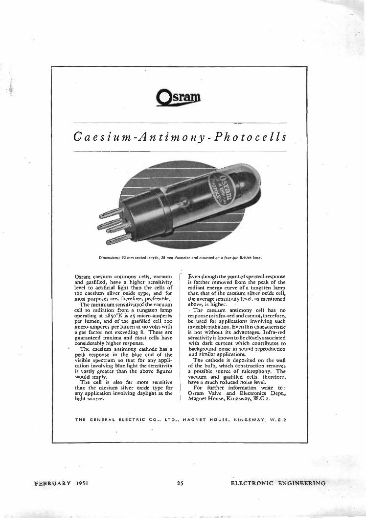
Caesium-Antimony-Photocells
Dimensions: 92 mm seated length, 28 mm diameter and mounted on a four-pin British base.
Osram caesium antimony cells, vacuum and gasfilled, have a higher sensitivity level to artificial light than the cells of the caesium silver oxide type, and for most purposes are, therefore, preferable. The minimum sensitivityof the vacuum
cell to radiation from a tungsten lamp operating at 2850°K is 25 micro-amperes per lumen, and of the gasfilled cell 12o micro-amperes per lumen at 90 volts with a gas factor not exceeding 8. These are guaranteed minima and most cells have considerably higher response. The caesium antimony cathode has a
peak response in the blue end of the visible spectrum so that for any appli-cation involving blue light the sensitivity is vastly greater than the above figures would imply. The cell is also far more sensitive
than the caesium silver oxide type for any application involving daylight as the light source.
Even though the point of spectral response is farther removed from the peak of the radiant energy curve of a tungsten lamp than that of the caesium silver oxide cell, the average sensitivity level, as mentioned above, is higher. • • The caesium antimony cell has no response to infra-red and cannot, therefore, be used for applications involving such invisible radiation. Even this characteristic is not without its advantages. Infra-red sensitivity is known to be closely associated with dark current which contributes to background noise in sound reproduction and similar applications. The cathode is deposited on the wall
of the bulb, which construction removes a possible source of microphony. The vacuum and gasfilled cells, therefore, have a much reduced noise level. For further information write to:
Osram Valve and Electronics Dept., Magnet House, Kingsway, W.C.2.
THE GENERAL ELECTRIC CO., LTD., MAGNET HOUSE, KINGSWAY, W.C.2
FEBRUARY 1951 25 ELECTRONIC ENGINEERING

j
Diagram by etturie,y 01 I cUraw Hal Pttb'e, Co. het.
for balanced and unbalanced measurement at frequencies between 1 Mc ,s and 100 1VIcis.
Wayne (; Kerr
THE WAYNE KERR LABORATORIES LIMITED, NEW MALDEN, SURREY. PHONE: MALDEN 2202
TYPE C.P.20A AMPLIFIER
For AC Mains and 12 volt working giving 15 watts output, has switch change-over from AC to DC and
" Standby " positions. Consumes only .5¡ amperes from 12 volt battery. Fitted with mu-metal shielded microphone transformer for k15.-ohm microphone, provision for crystal or moving iron pick-upiwith tone control for bass and top. Outputs for 7.5.-and 15 ohms. Complete in steel case with
- - PRICE £28. valves.
OTHER MODELS IN OUR RANGE OF AMPLIFIERS " SUPER-FIFTY WATT" - - - PRICE 36egns. " THIRTY WATT" „ 30¡igns. " 10-15 WATT RECORD REPRODUCER"
PRICE 25¡ gns. These are fitted in well ventilated steel cases with
recessed controls, as illustrated.
EXPORT ENQUIRIES INVITED
VORTEXION LIMITED 2 57-2 6 1 THE BROADWAY, WIMBLEDON, LONDON, S.W.19
Telephone: LIB 2814 and 6242-3 Telegrams: " Vortexion Wimble, London."
ELECTRONIC ENGINEERING 26 FEBRUARY 1951

TRANSMISSION
MEASURING SET
TYPE D-5I4-A
Í?oratory measurements of the frequency
response of filters, amplifiers, transformers
and other components usually require a con-
siderable amount of preparation, involving as
they do the use of an oscillator, an attenuator,
a valve voltmeter and various change-over
switches.
The Transmission Measuring Set Type D-514-A
combines all these items in one compact unit,
and with its aid gain or loss measurements of
up to 50 db at any frequency between Tooc/s
and 4okcis may be carried out immediately
with no preparation other than the connexion
of a power supply.
This instrument also finds many applications
in the field, especially for transmission measure-
ments on telephone and carrier telegraph
circuits. When an A.C. supply is not available,
the turn of a switch enables the power unit to
be operated from a 12 volt accumulator.
• FREQUENCY RANGE: toocis to 40 kc/s continu-ously variable.
• FREQUENCY ACCURACY: better than ±0.4% over entire range.
• POWER SUPPLY: A.C. mains ioo - 25o volts, 4c> - 6oc/s, or from a 12 volt accumulator.
• OSCILLATOR may be used separately, if desired.
• LAMP BRIDGE LEVEL METER: controls standard level of smW within ±o.zscib.
• RANGE OF MEASUREMENT: gain and loss up to 5o db at any frequency.
• OUTPUT IMPEDENCE: for use on 600 ohm circuits.
• PORTABLE: contained in two tough laminated plastic carrying cases.
MUIRHEAD & CO., LTD. BECKENHAM • KENT • ENGLAND
Please send me Bulletin B-610 fuliy describing the Trans-Million Measuring Set advertised in the "Electronic Engineering."
NAME
ADDRESS
MUIRHEAD PRECISION ELECTRICAL INST*TIME'f 'N . MAKERS
r- MUIR HEAD BECKENHAM • KENT • ENGLAND
sr CO. LTD. Telephone: BECkenham 0041 Telegrams and Cables MUIRHEADS ELMT-RS-r:ND
1
-J 37
FEBRUARY 1951 ELECTRONIC ENGINEERING
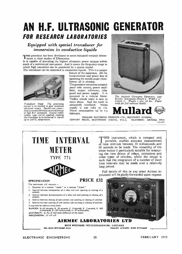
AN H.F. ULTRASONIC GENERATOR FOR RESEARCH LABORATORIES
Equipped with special transducer Jac immersion in conductive liquids
TH" generator has been developed to assist industrial research labora-tories in their studies of Ultrasonics.
It is capable of providing the highest ultrasonic power outputs within reach of a commercial instrument. And it covers the frequency range in which high intensities can be generated by a quartz crystal. The transducer can be immersed in conductive liquids. This is a unique
feature of the apparatus. All the inconvenience and power loss of operating the crystal under trans-former oil is avoided. The generator comprises a control panel with meters, power oscil-lator, output voltmeter, relay panel and power supply. It is mounted in a tubular frame. Trolley wheels make it easy to move about. And the cover is adequately ventilated. Mains supply is 230 Volts 50 C/S.
Power consumption up to 1.5 kilowatts.
Transducer Head. The generating crystal is air-backed to give maximum ultrasonic output. Special rear connec-tions to crystal eliminate corona discharge at high R.F. potentials. Sinitic rubber sealing rings can be supplied, enabling the transducer to be immersed in liquids up to 150°C. temperature.
The Mu/lard Ultrasonic Generator, type E.7562. Dimensions: Height 3'. Width I' 4'. Length 2'. Weight 2 cwt. 16 lbs. Please write for full technical details.
Mullard MULLARD ELECTRONIC PRODUCTS LTD., EQUIPMENT DIVISION,
CENTURY HOUSE, SHAFTESBURY AVENUE, W.C.2. TELEPHONE: GERRARD 7777 hit.347)
TIME INTERVAL METER TYPE 771
SPECIFICATION The instrument will measure:—
I. Duration of a contact " make " or a contact " break."
2. Interval between energisation of a relay coil and opening or closing of a contact.
3. Interval between de-energisation of a relay coil and opening or closing of a contact.
4. Interval between closing of one contact and opening or closing of another.
S. Interval between opening of one contact and opening or closing of another.
It may also be used as a stop clock.
RANGES: 0-60 seconds, 0-30 seconds, 0-6 seconds, 0-3 seconds, 0-600 milliseconds, 0-300 milliseconds, 0-60 milliseconds.
ACCURACY: ± 5% of half scale deflection of the meter. DIMENSIONS: 13' x x 6'.
THIS instrument, which is compact and portable, enables accurate measurement
of time intervals between 10 milliseconds and 60 seconds to be made. The versatility of the timer makes it particularly suitable for measur-ing the time delays of relays, contactors and other types of switches, whilst the design is such that the integration of a number of short time intervals may be made over a relatively long period.
Full details of this or any other Airmec in-strument will be gladly forwarded upon request.
PRICE £32
AIRMEC LABORATORIES LTD HIGH WYCOMBE • BUCKINGHAMSHIRE • ENGLAND
TEL: HIGH WYCOAIIII 2000 CABLES: EIRMEC 111011 WYCOMBE
ELECTRONIC ENGINEERING 28 FEBRUARY 1951
Northern Agents:
F. C. ROBINSON & PARTNERS LTD 287 Deansgate, Manchester 3
A NEW APPROACH TO AN OLD
PROBLEM...
The `CINTEL' AD
CORRECTOR is a new approach to the solution of this old prob-lem and enables the
phase distortion in any wide band amplifier of
75 ohms impedance to be corrected simply by
" turning a knob." For full technical details
please write for leaflet
No. PUCIll.
T'THERE are many prob-lems which confront the electronic engineer from day to day which may be regard-ed as" necessary evils" and one of these is the correction of phase-distortion in an amplifier.
USTABLE PHASE
CRUEL "4'9' co;totec-r
.1 b4 p ein•
set r,
so7.
'1, •
CINEMA-TELEVISION LIMITED A Company within the J. Arthur Rank Organisation
• Counters& Chronometers • Metal Detectors • Oscilloscopes • Photo-Electric
FOREMOST IN THE M ANUFACTURE OF —
Cells • Cathode Ray Tubes • Geiger-Muller Tubes • Electronic Instruments
WORSLEY BRIDGE ROAD • LONDON • S•E•26 Telephone: HITher Green 4600
Scottish Agents: ATKINS, ROBERTSON & WHITEFORD LTD
100 Torrisdale Street, Glasgow S.2
29
OISTC TM.« MAIM
ELECTRONIC ENGINEERING
FEBRUARY 1951

aO CHM
or CO-AXIAL CABLES
These plugs and sockets are designed for use with either solid or
airspaced dielectric cables. The patented
method of connecting the plug to the metal
braiding of the cable ensures positive con-
tact and grip without soldering. The
centre conductor of the cable passes
through the hollow centre pin for easy
soldering. The thermosetting plastic
insulating material between the plug body
and pin remains unaffected by heat from
soldering. The socket with two-hole
mounting flange incorporates a 'click'
action retaining spring which prevents the
plug from loosening through vibration.
Both plug and socket bodies are of Nickel-
plated brass, and the contact pins are
Silver-plated brass.
BRIEF SPECIFICATION
These Plugs and Sockets are manufactured
to an R.E.C.M.F. Specification, and the
minimum performance figures after testing
to RCl/r Yellow Specification Itsicturimo
TROPICAL EXPOSURE TEST, are :—
Capacity (Plug and Socket together) ...
Contact Resistance (Outer Contacts) ...
Contact Resistance (Pin Con-tacts) ... 10 milliohms max.
Leakage Resistance 10 Megohms min. Steady withdrawal force ... 6/16 lb.
5 pF max.
10 milliohms max.
PAT. NO. 637613
ANTIFERENCr pi LIMITED L
ANTIFERENCE LIMITED, 67 BRYANSTON STREET, MARBLE ARCH, LONDON, W.I. Telephone : PADdington 7253 P.B.X.
VARIABLE--BUT DEPENDABLE
The value of the EGEN midget pre-set variable resistor
to the television and electronics designer has been enhanced
by a new double slider operating on the radius of the element, giving greater stability and making accurate adjustment
easier. This reliable, precision engineered component can
also be supplied mounted in a series of one, two or three
on a common panel which can be suitably engraved. Available
in any value from so ohms. to 25,000 ohms.
• Sizefxrrxr
• Worm drive for smooth action
• Ratchet action prevents over-winding
• Silver-plated solder tags
EGEN ELECTRIC LTD. Charfleet Industrial Estate, Canvey Island,
Essex. 'Phone Canvey 60 POTENTIOMETERS
/ 1\
<WODEJI> COMPOUND FILLED NSF ER CO. LTD
TRANSFORMERS L CHOKES for
UTMOST
RELIABILITY Woden Compound Filled transform-ers have been developed for use in exacting industrial and climatic conditions and have the following features :---
• Complete moisture-proof filling compound • Universal fixing for above or below chassis wiring
• Constant fixing cccc nd Il size
• Occupy minimum space and ensure clean and compact layout
Send for latest catalogue;
WORN TRANSFORMER CO, LTD., MOXLEY ROAD, BILSTON, STAFFS.
I .T.I—
ELECTRONIC ENGINEERING 3(1 FEBRUARY 1951

3o amps at 25o volts a.c. .
that is the duty of each pair of contacts of the newAustinlite ' Thirty'-and there can be up to 24 of them.
The ' Thirty' is an entirely new switch designed
for those jobs where the Austinlite ' Fifty ' is
unnecessarily large : it's a compact and robust
rotary for multi -circuit and sequence switching,
made up from I, 2, 3, 4, 5 or 6 cells. Each cell contains
4 fixed, and up to 4 moving contacts : there is an ' off'
position between each contact position. A very large number
of contact combinations is possible and very complex circuits can be
handled. Capacity at unity power factor : 450 volts -15 amps : 25o volts -
30 amps. Higher voltages can be dealt with at lower currents and vice -versa. The
Austinlite `Thirty' leaflet describes the switch in detail and will be sent on request.
GtAA....-Ce- PRODUCT
AUSTINLITE LIMITED, DEPT. A5, LIGHTHOUSE WORKS, SMETHWICK 40, BIRMINGHAM
400les410,te. eleaddefteheby
UNITED INSULATOR CO. LTD. OAKCROFT RD. TOLWORTH SURBITON SURREYTELEPHONE: ELMBRIDGE 51.41 CABLES CALANEL, SURBITON
FEBRUARY 1951 31 ELECTRONIC ENGINEERING

A GREAT NAMEpaves the way to greater knowledge
Marconi's acknowledged leadership in the whole fieldof radio, as we know it today, is based on the surefoundation of scient;fic training. Fifty years agoMarconi's established the world's first school of wirelessengineering, a source of knowledge to which have come
students of all colours, classes and creeds from all thecorners of the earth ; a small building devoted not totechnical instruction alone, but also to suggesting thewider potentialities of radio for man's good in the verysmall and troubled world in which we live.
MarconiTHE FIRST AND GREATEST NAME IN WIRELESS
MARCONI'S WIRELESS TELEGRAPH COMPANY LIMITED MARCONI HOUSE CHELMSFORD ESSEX
mossimoms wilily
PAINTON & CO LTD KINGSTHORPE NORTHAMPTON
ELECTRONIC ENGINEERING 32 FEBRUARY 1951
E.M.I. TRAINING for the best posts
E.M.I. INSTITUTES, THE COLLEGE BACKED BY THE GREATEST ELECTRONIC INDUSTRY IN THE EMPIRE.
DAYTIME ATTENDANCE COURSES
• Principles and Practice of Radio—1 year.
• Telecommunications Engineering-2 years (leading to City and Guilds Final Certificate).
• Electronic Engineering-3 years (including one year's practical training in factories)—leading to City and Guilds Full Technological Certificate.
* Next courses commence April, 1951.
Early enrolment is advised.
Moderate Terms. Facilities for easy payment.
Write for free Brochure to the Registrar, Dept. 11.
E.M.I. INSTITUTES 10.PEMBRIDGE SQUARE, NOTTING Hilt GATE. LONBBN, W 2. TELEPHONE: BAYSWATER 5131/2
Associated with
MARCONIPHONE
COLUMBIA ETC.
1.18.
neet€ .
HIGH WYCOMBE
1921/2 ee- ,e-del•le41 tP ,e
Pee's' e - e- - - , - di fleielee e-gf e - -
eit,g...,...ei.g...• e e
TOOL MAKERS
MOULDERS • ASSEMBLERS
TUBE MAKERS
AID Approeed
the value of
ddg COLLOIDAL GRAPHITE
to the electronic engineer
Because of their unusual properties 'dag' dispersions
of colloidal graphite are constantly finding new
applications in the electronics industry.
The films formed possess :—
Good electrical
and thermal conductivity and radiation.
Inertness to E.M. radiation and electron
bombardment.
Opacity, Diamagnetism, Chemical inertness.
Applied by brush, spray or dip, they may be used as :—
Electrodes in Cathode Ray Tubes, Geiger counters,
radiation meters.
Conducting coatings for bleeding off static.
Screens on T.V. cabinets to suppress
E.H.T. radiation.
Resistors—printed and conventional types.
ELCO PLASTICS LTD.
TUBE LAMINATION LTD L
PLASTICRAFT WORKS
DESBOROUGH PARK ROAD, HIGH INYCOMBE, BUCKS.
POST THIS -COUPON TO-DAY
TO: ACHESON COLLOIDS LIMITED
IS. PALL MALL, LONDON, S.VV.I
Please send me additional information on the above or other
applications for ' dag' in the field of electronics.
NAME
ADDRESS
D/I8
1M1 111 11 MM.
FEBRUARY 1951 33 ELECTRONIC ENGINEERING

* The Basis of World Standards
TELCON R.F. CABLES Technical excellence supported by constant research and an unrivalled knowledge and experience of Radio Frequency Cable applications, ensures the continuance of the lead established by TELCON in this field.
Even before the introduction of Telcothene* as a cable dielectric, an application pioneered by TELCON, a range of Radio Frequency cables with unique capacity and attenuation characteristics was produced, using Telconax.
Today, developments are still going on and the solution of any problems involving the application of Radio Frequency, cables will be found in the wide range manufactured by TELCON
* Telcothene (Regd.)-Polythene processed by TeIcon so provide specific characteristics
Ask also for details of
TELCON METALS THE TELEGRAPH CONSTRUCTION & MAINTENANCE CO. LTDTeLtoPi
Head Office : 22, Old Broad Street, London, E.C.2. Tel : LONdon Wall 7104
Enquiries to: Telcon Works, Greenwich, S.E.I0. Tel : GREenwich 3291
---DONOVAN ACCESSORIES-FOR THE ELECTRONIC APPARATUS MANUFACTURER!
titiwit44
CMS
•TYPE 1.96 TERMINAL BLOCKS. Made i15 n ,
30 and 60 amp. sizes.
Type C.30 PUSH-BUTTON UNIT arranged for mounting on customers' own cover
plate.
Type A.I I A.C. POWER RELAY - 4-pole with N.O.
or N.C. contacts.
THE DONOVAN ELECTRICAL CO. LTD.
Safuse Works • Stechford • Birmingham 9
VALVES ALL GUARANTEED NEW & BOXED. SOME GOVERNMENT SURPLUS.
6V6GT. 6/6. 6V6G. 6/6. 6AC7. 6/3. 5Z4M. 6/ -. 6X5. 6/, 5U4G. 6/.. 6F6. 61, EE39. 6/.. EL32. 6/, 807. 6/, IC5. 6!, EK32. 6/, 6L6. 9/.. IC5. 616. H63. 7/,
VRI37. 5/, MS/PEN. 9/-. 9D2. 4/9. 6H6. 3/ -. IS4. 7/3. 155. 7/3. IRS. 7/3. 3S4. 7/3. IT4. 7/3. 41. 7/... 42. 7/, 77. 7/, 78. 7/, 80. 7/ -. 25A60. 71,
25L6G. 7/, 6C6. 7/, 6D6. 7/ -. 6C5. 7/, DDL4. 4/6. 6SK7. 4/9. I2K8. 6/9. 7Q7. 6/6. U18. 7/6. EF8. 7/6. CV6. 1/6. 6.15. 3/9. 6J7. 5/9. 37. 4/9. EF50. 7/ -.
6K7. 5/6. 6SH7. 3/6. 6Q7. 6/6. I2A6. 5/9. VUI I I. 4/6. EC52. 5/6. EBC33. 5/6. EA50. 2/6. SP6I. 3/6. SP41. 2/6. 12H6. 4/6. 5Y4. 6/9. 5Y3. 71, EF50. 8/, Sylvania.
TERMS: C.W.O. or C.O.D. Accounts. two trade references, please.
Carriage paid over £1. Wiite for Component and Valve Lists to :-
WILLIAM CARVIS, 103, NORTH STREET, LEEDS, 7
I II C1111:11n[ri HAVE YOU HAD YOUR COPY OF "ENGINEERING OPPORTUNITIES"? Whatever your sae or experience--you must read this highly informative guide to the best paid engineering posts. The hand-book contains particulars of A.M.LC.E., A.M.I.NLI., A.M.Brit.I.R.E., and other important Engineering Examinations, and outlines home-study courses in all branches of Civil, Mechanical, Electrical, Automobile, Radio and Aeronautical Engineering, Government Employment, Draughtsmanship, Building and Plastics. Matriculation, etc. We Guarantee " NO PASS - NO FEE" If you are earning less than £10 a week you cannot afford to miss reading "Engineering Opportunities". It tells you everything you want tabknow to secure your future. Write for this r nlightening gui I, to well paid posts NOW-FREE and without cbliiiaticn.
BRITISH INSTITUTE OF ENGINEERING TECH NOLOGY
Ma Shakespeare Hse., 17 18 Stratford Plac e, London W1 B/ET
ELECTRONIC' ENGINFFRING 34 1 LBRUARY 1951

The Universal Bridge Type TF 868 is one of the most sought-after Marconi instruments and, for the first time, is available for immediate delivery.
RANGE
L — 100 I-1 C I , F — 100F R 0.1t — 10 MS1
PHASE ANGLE 0- oo
ACCURACY •1 1
o ..Ne ., , ' e«C e?...`à
" / ,." - _•.. <<, .....„
z 0..""- ,e ' Ç..) ge
MARCONI
.4„.4cv
<4•,>
INSTRUMENTS LIMITED ST ALBANS, HERTFORDSHIRE Telephone: St Albans 6161/5 •
Northern Office : 30 Alblon Street, Hat. Midland Office : 19 The Parade, Leamington Spa. Southern Office and Showrooms: 109 Eaton Square, London, S.W.I.
MAGNETIC RECORDING EQUIPMENT MODEL 5 TAPE DESK
2 Speeds, three heads, Push Button Control. Price £37 10s.
MAGNETIC HEADS High quality Record/Play and Erase Heads as fitted to the Model 5 Tape Desk. Types 5RP and 5E. Price : £3 5s. each.
Frequency Ranges Tape Speed 60-5,500 C.P.S. 3r per sec. 30-11,000 C.P.S. 71" per sec.
(Using best quality tape).
Stocks of E.M.I., G.E.C. and DUREX Tape and spare reels also Oscillator Coils.
TRADE SUPPLIED . .
BRADMATIC LIMITED STATION ROAD • ASTON • BIRMINGHAM 6 Tcleph, ,ne : irç7.1 Telegrams : Bradmatic, Birmingham.
The PYROBIT NEON TESTER DETECTS Voltages as low as
50 A.C. or 70 D.C. because it contains the most sensitive Neon
Bulb ever made.
Averabe life 25,000 hours. Can
be used up to 750 V.
Made by the
ACRU ELECTRIC Tool Mfg. Co. Ltd.
123 Hyde Re d • Arewick • Mancheltc r
As specialists to the Elec-tronic Industry, may we have the opportunity to quote you on your pressing requirements. We have a special department for enamel finishing to order.
WILLIAM PEARCE LTD.
ORMOND STREET, BIRMINGHAM, I 9
FEBRUARY 1951 35 ELECTRONIC ENGINEERING

foremost with Stabilised Power Supply Units Type 1930 ; + 220 to 380V variable;
1-100mA ; regulation .5% ; ripple 2.5mV.
Negative stabilised-150V at 20mA.
Delivery
ex Stock
Heater supplies-6'3V, 4V and 2.3V A.C,
FURZEHILL LABORATORIES LTD., BOREHAM
TEL : ELStree 3910.
WOOD, HERTS.
CASTLE ENGINEERING COMPANY (NOTTINGHAM) LIMITED
HAStAM STREET• CASTLE BOULEVARO•NOTTINGHAM
46068
5328 0
TUNGSTEN Contacts, Rods, Pins, Lead-in-
Wires, Targets, Shaped Components, Heater Wires, Spark Gaps.
MOLYBDENUM Tubes, Nuts, Bolts, Per-
forated Sheets, Coils, Spirals, and ;other Components made from High Refractory Metals to Customers' Design.
ELECTRO -ALLOYS L", 12, BRUNEL ROAD, LONDON, W.3
Telephone SHE 3460, 3031
Technical Excellence
combines with beauty and soundness of DESIGN in the
OXLEY * DIFFERENTIAL AIR
DIELECTRIC TRIMMER
Widtb. 18.5 111/.11 Lrogth. 3d MP. Height:
1.5 to 13pF —8 ail. 1.8 t. 2081,-2•5 own 2 to 26pP-11.5 golsa 2 to 32pF-12.3 mío
Law: Eltriught line capacity Power Factor: Less thus -001 " Ineolation: Over 2.000 megols,o• Voltace: 500 D.C.
OXLEY DEVELOPMENTS CO., VW., ULVERSTON, N. LANCS. TEL. • ULVERSTON 330e
ELECTRONIC ENGINEERING 36 FEBRUARY 1951

RELAYS
111110°'00001 gioijoroPoole'-gooMmbiu="'
QUALITY RELIABILITY
r7,iuedeezetee-- 6-K /e-e t9nizedey)
&edecee% Eddie se ARDNERS
SOMERFORD • CHRISTCHURCH • HANTS TELEPHONE: CHRISTCHURCH 1025
HIGH-CAPACITY PRECISION MICA CONDENSERS
By leading manufacturers. Accuracy plus or minus 0.5 (point five) per cent of stated value. Pure mica and copper foil. (a) 0.017970µF (b) 0.023570µF (c) 0.035020µF Id ) 0.040710µF (e) 0.055820µF (f) 0.06S350µF
Many close tolerance standard parallel or other combinations
Special terms to manufacturers, bodies. Post or carriage extra.
I/3d. I/3d. I/6d. I/6d. 116d. I/6d.
(g) 0.087460µF (h) 0.10843SµF (i) 0.123750µF (I) O. I 47000µF (k)0.205276µF
values may be made up by of above, e.g. —.0•5µF; c+f universities, or other research
GARLAND BROS. DEPT. 55
Chesharn House, Deptford Broadway, London, S.E.8. Phone : T1Deway 4412/3.
MAGNETIC RELAYS
LARGEST STOCK IN GREAT BRITAIN OF RELAYS,
KEY SWITCHES AND UNISELECTORS
Government Contractors
P.O. 3000 — 600 — HIGH SPEED Also 230y. A.C. 50cy.
ALL NEW EX-MINISTRY GOODS
JACK DAVIS (Relays) LTD. DEPT. E.E. 36 PERCY STREET, LONDON, W.1.
Phones: MUSeum 7960 LANgham 4821
DC/AC • CONVERTER
the A.C.poweryou require from your D.C. supply
Models for Electric Gramophones from fa, plus 10%
Models for • Radio-Grams (Incl. 3-speed mtrs.)
• Autochange Radio-Grams • Radios • Televisions, etc., from
£10 • 15s. plus 10% Input 6, 12, 24, 32, SO, 11 0 or 200/250 y D.C. Output 230 y 50 or 60 c/s
Descriptive literature from the manufacturers :—
.eff. 57 FORTESS ROAD, LONDON, N.W.5 Telephone : GULliver 5165
Overseas Enquiries to nearest E.M.I. Organisation Depot.
FEBRUARY 1951 37 ELECTRONIC ENGINEERING
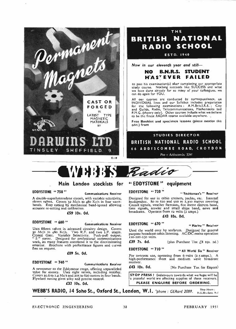
CAST OR FORGED
IN
LATEST TYPE MAGNETIC MATERIALS
BY
DRRIIIIRS LTD TINSLEY SHEFFIELD. 9.
0.18
Main London London stockists for
EDDYSTONE " 750" Communications Receiver A double-superheterodyne circuit, with variable selectivity, eleven valves. Covers 32 Mc/s to 480 Kc/s in four wave-bands. Easy tuning by mechanical band-spread allowing accurate re-setting and calibration
£59 10s. Od.
EDDYSTONE " 680" Communications Receiver Uses fifteen valves in advanced circuitry design. Covers 30 Mc/s to 480 Kc/s. Two R.F. and two I.F. stages. Crystal Gate. Variable Selectivity. Push-pull output. " S " meter. Designed for professional communications work, its many features commend it to the discriminating amateur. Brochure with performance figures and curves free on request.
£89 Ss. Od.
EDDYSTONE «4 740 " Communications Receiver
A newcomer to the Eddystone range, offering unparalleled value for money. Uses eight valves, including rectifier. Covers 30.6 to 1.4 Mc/s and 205 to 620 metres in four bands. Flywheel tuning gives silky and precise control.
£32 10s. Od.
THE
BRITISH NATIONAL RADIO SCHOOL
ESTD. 1940
Now in our eleventh year and still—
NO B.N.R.S. STUDENT H'AS T EVER FAILED
to pass his examination(s) after completing our appropriate study course. Nothing succeeds like SUCCESS and what we have done already for so many of your colleagues, we can do again for YOU.
All our courses are conducted by correspondence, on INDIVIDUAL lines and our Syllabus includes preparation for the following examinations : A.M.Brit.I.R.E. ; City and Guilds, Radio, Telecommunications, Mathematics and P.M.G. (theory only). Other courses include what we believe to be the finest RADAR course available anywhere. ,
Free Booklet and specimen lessons (please mention this advt.) from
STUDIES DIRECTOR
BRITISH NATIONAL RADIO SCHOOL 66 ADDISCOMBE ROAD, CROYDON
Pho Addisconib, 3341
" EDDYSTONE" equipment
EDDYSTONE " 720 " " Yachtsman's" Receiver
Designed for use in cabin cruisers, yachts, etc. Internal loudspeaker. 80 to 620 and 900 to 2,300 metres covering Consol signals, weather forecasts, 600 metre distress band, time signals, trawler and small ships band, news and broadcasts. Operates from 12 volts (2 amps.).
£43 10s. Od.
EDDYSTONE " 670" " Marine " Receiver Used the world over by seafarers. Designed for general purpose broadcast cabin listening. AC/DC mains operation 110-200-230 volts.
£39 7s. 6d.
EDDYSTONE " 710 "
(plus Purchase Tax £8 isis. 2d.)
" All World Six " Receiver
For overseas use, operating from 6-volts (2.5 amps.). A high-performance short and medium wave broadcast receiver.
£43 10s. Od. (No Purchase Tax for Export)
ISTOP PRESS ! Endeavours towards what we hope will be a peaceful world are affecting supplies of these receivers.
PLEASE ENQUIRE BEFORE ORDERING.
WEBB'S RADIO, 14 Soho St., Oxford St., London, W.I. 'phone: GERard 2089. 9_,D7coutris..9_,
ELECTRONIC ENGINEERING FEBRUARY 1951

spells Quality in Tape and Wire Recording
Record, Playback and Erase Heads, Record-playback Amplifiers, Oscillator Coils and Units, Tape
Mechanisms, TAPE and SPOOLS We also specialise in :
HIGH-ACCURACY COUNTING DEVICES Development of electronic applications to industry
Telephone : NORthern 2084
Manufactured by
'' arie IJZOICIIRAPIE
Telegrams : Audigraph Birmingham.
Dept, MR7, 74 Gt. Hampton St., Hockley, Birmingham 18. 5..62 A
M ICA ODD 5C§
ODOAPIFIPAGeS. ELEMEKFIT §VEROPS
CONDE fkl§lEfR PIA1TE5 §PECOAIL §0-1APES
[RAW MO CA, WAS,DIERS
ac
MICA C9 UP-BEDFORD.
PRECISION EQUIPMENT by AUTOSPARES Square Wave Generator. AC mains, enclosed cabinet £12. Screen Modulator for lkw £10. Modulation transformers 25/-. Miniature 3-valve volume Expander/Compressors £3. RF Scopes 3" £10, 5" £12, Oscilloscopes EIS. Tape Recorder Amplifiers £10, CIS and £111. Type 38 Walky Talky transceivers 45/-. ATP 4 valves SM. 6-valve AC/DC De Luxe Amplifiers, Mu Metal output transformer.
listed 4Sgns. three at £18. 15 watt 6L6 Amplifier £10. 7 watt minature 85/-. 10' Cabinet speakers, GEC 35/, GI2 walnut floor cabinet Lis,
ee Mahogany baffle on castors £8. Ecko 8-valve All Wave motor tuned table consoles 18gns. HP
terms £3 down. Push Pull 15/20 watt output transformers 9/-. Potted Chokes 50 mia 7/6d., 100 m/a 9/6.. 75 mia 6/-.
Powerful amplifiers and Receivers, instruments, circuits, HP terms. Illustrated leaflets. Radiograms Modernised.
AUTOSPARES 180 HIGH STREET, TOOTING, LONDON, S.W.I7
POTENTIOMETERS
RELIANCE 4.
Wire-wound and Composition types. Single. Ganged, Tandem Units.
Characteristics : linear, log., semi-log., non-inductive, etc. Full details on request.
RELIANCE MNFG., CO. (SOUTHWARK), LTD., Sutherland Road, Higham Hill, Walthamstow, E.17
Telephone: Larkswood 3245
• Calibrated Peak to Peak Source. 1% accuracy
• Special Peak to Peak Measuring circuit
• Small, robust, easily portable
• Overall size e x 9- x 51- deep
*Reasonably priced
*Immediate delivery
to meet
the specific
demand for an
inexpensive
C.R.O. and
Amplifier
Calibrator
This instrument is a Peak to Peak calibrated A.C. source for calibrating Cathode Ray Oscilloscopes and Ampli-fiers. Output is from 1 millivolt to 100 volts (balanced or unbalanced) in ten switched steps, monitored by a special peak to peak measuring voltmeter circuit.
Write to BRITISH ELECTRONIC INDUSTRIES,
28. Upper Richmond Rd., 5.W.15. Tel.: VANdyke 1856
MIGHTY
PARTICLE
Wherever natural or synthetic rubber is important, there is the case for DAINITE.
MOULDED RUBBERS
HARBORO' RUBBER CO., LTD.. MARKET HARBOROUGH
SYNTHETIC RESIN LAMINATED MATERIALS
SHEET, ROD AND TUBE IN ALL DIMENSIONS
BOBBINS & COIL FORMERS TO ANY SPECIFICATION
er g •s•
CPA
MICA AND MICANITE SHEET AND MANUFACTURED PARTS
MICA & MICANITE SUPPLIES LTD., BARNSBURY SQUARE, LONDON, N.I.
Telephone : NORth 3032 5 Telegrams : MICASULIM - LONDON
FEBRUARY 1951 39 ELECTRONIC ENGINEERING

INDEX TO ADVERTISERS
Acheson Colloids Ltd. Acru Electric Tool Mfg. Co., Ltd.. The Aimee Laboratories Ltd. All-Power Transformers Ltd. Anliference Ltd. Audigraph Ltd. kutospares
Belling & Lee Ltd. Bradmatic Ltd. British Electronic Industries British Institute of Engineering Tech-
nology . • British Mica Co., Ltd. .. . British National Radio School. The .
British Thomson-Houston Co.. Ltd., The Bullets Ltd. .
33 Edison Swan Electric Co., Ltd., The 35 Egen Electric Ltd. 28 Elco Plastics Ltd. 24 Electro Alloys Ltd. 30 E.M.I. Factories Ltd. 39 E.M.I. Institutes Ltd... 39 E.M.I. Sales & Service Ltd. ..
English Electric Co., Ltd., The
14 35 39
34 39 38 15 16
Carvis, William .. .. 34 Castle Engineering Co. (Nottingham)
Ltd., The Caxton Publishing Co.. The 74 Chance Bros. 31 Chapman & Hall Ltd. . 75 Cinema-Television Ltd. 29 Cole Ltd.. E. K. . 3 Connolly's (Blackley) Ltd. 22 Cossor Ltd., A. C. 17
Da twins Ltd. Davis (Relays) Ltd., Jack De La Rue & Co., Ltd., Thomas Donovan Electrical Co., Ltd.
36
38 37 21 34
Ferranti Ltd. Furzehill Laboratories Ltd.
12 33 20
Cover ii
18
36
Gardner's Radio Ltd. 37 Garland Bros. . 37 General Electric Co.. Ltd.. The 25 General Engineering Co. (Radcliffe) Ltd. 10
Hatboro' Rubber Co., Ltd., The Hazlehurst Designs Ltd. . Hoplon Radio
Oxley Developments Co., Ltd. 13 30 33 36 Painton & Co., Ltd.
Parmeko .
Partridge Transformen Ltd. .. Pearce (Pressings) Ltd., William Pell Control Ltd., Oliver
Radiospares Ltd.. . Reliance Mnfg. (Southwark) Ltd.
36
32 19
35 It
8 39
Sangamo-Weston Ltd. .. Cover iii Standard Telephones & Cables Ltd. .. 5
Telegraph Condenser Co.. Ltd., The 9 39 Telegraph Construction & Maintenance
Cover i Co.. Ltd., The . . 34 Tufnol Ltd. 23
London Electric Wire Co. & Smiths Ltd. 24
Marconi Instruments Ltd. Marconi's Wireless Telegraph Co., Ltd. Measuring Instrnments (Pullin) Ltd. Metropolitan-Vickers Electrical Co., Ltd. Mica & Micanite Supplies Ltd. Mnirhead & Co., Ltd. Mallard Electronic Products Ltd. 7 and Murex Ltd.
Nagard Ltd.
35 32 40 11 39 27
28 22
3
United Insulator Co., Ltd.
Valradio Ltd. Vortexion Ltd.
31
37 26
Walter Instruments Ltd. Cover iv Wayne-Kerr Laboratories Ltd., The 26 Webb's Radio .. . 38 Whiteley Electrical Co.. Ltd. 21 Woden Transformer Co.. Ltd. .. 30
These three rectangular instruments are designed on symmetrical lines, thus giving a distinctive clear open scale and pleasing appearance. Each size available in all standard ranges. The Series 65 and
35 can be fitted with dial illumination.
Printed in Great Britain by The Press at Coombelands, Ltd., Addlestone, Surrey, for the Proprietors, Morgan Brothers (Publishers) Ltd., 28, Essex Street, Strand, W.C.2. Registered for Transmission by Canadian Magazine Post

WESTON 12-INCII SCALE LABORATORY STANDARDS For measurements of extreme accuracy in laboratory, research and
industrial use. ACCURACY 0-1 per cent.
1111111101111111111111111M11011111Wietel
11101111111111111111K
\Mtlit&%‘\‘11
SANGAIVIO WESTON LIMITED ENFIELD MIDDLESEX • Tel.: Enfield 3434 (6 lines) and 1242 (4 lines)
Grams: Sanwest, Enfield. Branches:
GLASGOW MANCHESTER, NEWCASTLE-ON-TYNE, LEEDS, WOLVERHAMPTON.
BRISTOL, SOUTHAMPTON, BRIGHTON, LIVERPOOL & NOTTINGHAM.
11% Ammaminumimminurem
ELECTRONIC ENGINEERING FEBRUARY 1951

Ors Sir -
that's mq baby. If you have only limited space and require only simple
switching, then the Type B.T. is the switch you need. It is a
midget, and has been specially designed for small spaces. Here
are some new features which we have recently included
Ati'e
Wailer barman's
fo e t.1/ e
SVOICHES---tet.De
1,111‘111TED
GARTH ROAD, LOWER MORDEN. SURREY TELEPHONE: DERWENT 4421-2 -3
• The contact blades are fixed in a new way. This makes them completely rigid all the time.
Ca The drive spindle is positioned definitely in the wafer. This provides double bearing.
• Steady contact resistance.
• Improved insulation between contacts.
• Positive contact.
• Self-cleaning action.
It ought to be good? It is goon — sensible and efficient. It will last you a long time.
CR( 45
ELECTRONIC ENGINEERING iv FEBRUARY 1951