ha‐dsp user manual.pdf · dsp processor. the ha‐dsp incorporates a powerful set of features...
TRANSCRIPT
miniDSP Ltd, Hong Kong / www.minidsp.com / Features and specifications subject to change without prior notice 1
HA‐DSP DSP‐ENABLED PORTABLE HEADPHONE AMPLIFIER
User Manual
miniDSP Ltd, Hong Kong / www.minidsp.com / Features and specifications subject to change without prior notice 2
Revision history
Revision Description Date V0.2 Preliminary version 12 June 2017
V0.3 Updated for released plugin 28 June 2017
miniDSP Ltd, Hong Kong / www.minidsp.com / Features and specifications subject to change without prior notice 3
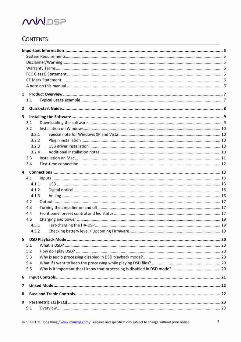
CONTENTS
Important Information ..................................................................................................................................... 5
System Requirements ............................................................................................................................................ 5
Disclaimer/Warning ............................................................................................................................................... 5
Warranty Terms ..................................................................................................................................................... 6
FCC Class B Statement ........................................................................................................................................... 6
CE Mark Statement ................................................................................................................................................ 6
A note on this manual ........................................................................................................................................... 6
1 Product Overview ...................................................................................................................................... 7
1.1 Typical usage example ............................................................................................................................... 7
2 Quick‐start Guide ....................................................................................................................................... 8
3 Installing the Software ............................................................................................................................... 9
3.1 Downloading the software ........................................................................................................................ 9
3.2 Installation on Windows .......................................................................................................................... 10
3.2.1 Special note for Windows XP and Vista ........................................................................................... 10
3.2.2 Plugin installation ............................................................................................................................ 10
3.2.3 USB driver installation ..................................................................................................................... 10
3.2.4 Additional installation notes ........................................................................................................... 10
3.3 Installation on Mac .................................................................................................................................. 11
3.4 First‐time connection .............................................................................................................................. 12
4 Connections ............................................................................................................................................. 13
4.1 Inputs ....................................................................................................................................................... 13
4.1.1 USB .................................................................................................................................................. 13
4.1.2 Digital optical ................................................................................................................................... 15
4.1.3 Analog .............................................................................................................................................. 16
4.2 Output ..................................................................................................................................................... 17
4.3 Turning the amplifier on and off ............................................................................................................. 17
4.4 Front panel preset control and led status ............................................................................................... 17
4.5 Charging and power ................................................................................................................................ 19
4.5.1 Fast‐charging the HA‐DSP ................................................................................................................ 19
4.5.2 Checking battery level / Upcoming Firmware. ................................................................................ 19
5 DSD Playback Mode ................................................................................................................................. 20
5.1 What is DSD? ........................................................................................................................................... 20
5.2 How do I play DSD? ................................................................................................................................. 20
5.3 Why is audio processing disabled in DSD playback mode? ..................................................................... 20
5.4 What if I want to keep the processing while playing DSD files? ............................................................. 20
5.5 Why is it important that I know that processing is disabled in DSD mode? ........................................... 20
6 Input Controls .......................................................................................................................................... 21
7 Linked Mode ............................................................................................................................................ 22
8 Bass and Treble Controls .......................................................................................................................... 22
9 Parametric EQ (PEQ) ................................................................................................................................ 23
9.1 Overview .................................................................................................................................................. 23

miniDSP Ltd, Hong Kong / www.minidsp.com / Features and specifications subject to change without prior notice 4
9.2 Types of filter ........................................................................................................................................... 23
9.2.1 PEAK ................................................................................................................................................. 24
9.2.2 LOW_SHELF and HIGH_SHELF ......................................................................................................... 24
9.2.3 ALL_PASS ......................................................................................................................................... 24
10 Configuration Presets .............................................................................................................................. 25
10.1 Saving and loading presets ...................................................................................................................... 25
10.2 Restoring defaults .................................................................................................................................... 26
10.3 Synchronizing options ............................................................................................................................. 26
11 Avoiding Clipping ..................................................................................................................................... 27
11.1 A simple example .................................................................................................................................... 28
11.2 A more realistic example ......................................................................................................................... 29
11.3 The “no gain” approach ........................................................................................................................... 30
12 Advanced Topics ...................................................................................................................................... 31
12.1 PEQ advanced mode ................................................................................................................................ 31
12.1.1 What’s a “biquad? ........................................................................................................................... 31
12.1.2 Advanced mode for a single filter ................................................................................................... 31
12.1.3 Parametric EQ file import (REW integration) .................................................................................. 32
12.1.4 Biquad design software ................................................................................................................... 32
12.2 FIR filtering and routing ........................................................................................................................... 33
12.2.1 FIR filtering overview ....................................................................................................................... 34
12.2.2 FIR filter design software ................................................................................................................. 34
12.2.3 Filter file format ............................................................................................................................... 34
12.2.4 Loading filter coefficients ................................................................................................................ 35
12.2.5 Routing section ................................................................................................................................ 35
13 Specifications ........................................................................................................................................... 37
13.1 Firmware upgrade ................................................................................................................................... 38
13.1.1 Windows .......................................................................................................................................... 38
13.1.2 Mac OS X .......................................................................................................................................... 40

miniDSP Ltd, Hong Kong / www.minidsp.com / Features and specifications subject to change without prior notice 5
IMPORTANT INFORMATION
Please read the following information before use. In case of any questions, please contact miniDSP via the
support portal at minidsp.desk.com.
SYSTEM REQUIREMENTS
To configure the miniDSP audio processor, you will require a Windows PC or Apple Mac OS X computer with
the following minimum specification:
Windows
PC with 1GHz or higher processor clock speed. Intel® Pentium®/Celeron® family, or AMD K6®/AMD
Athlon®/AMD Duron® family, or compatible processor recommended.
512 megabytes (MB) of RAM or higher
Keyboard and mouse or compatible pointing device
USB 2.0 port
Microsoft• ® Windows® Vista® SP1/ XP pro SP2/Win7/Win8.1/Win10
Microsoft• ® .NET framework v3.5 or later
Adobe AIR environment (latest version)
Adobe Flash player (latest version)
Mac OS X
Intel‐based Mac with 1 GHz or higher processor clock speed
512 megabytes (MB) of RAM or higher
Keyboard and mouse or compatible pointing device
USB 2.0 port
Mac OS X 10.8 or higher
Adobe AIR environment (latest version)
Adobe Flash player (latest version)
DISCLAIMER/WARNING
miniDSP cannot be held responsible for any damage that may result from the improper use of this product
or incorrect configuration of its settings. As with any other product, we recommend that you carefully read
this manual and other technical notes to ensure that you fully understand how to operate this product. The
miniDSP audio processor is a powerful tool, and misuse or misconfiguration, such as incorrectly set gains or
excessive boost, can produce signals that may damage your audio system.
As a general guideline, you should perform the initial configuration of the miniDSP audio processor before
enabling audio through any connected output device or amplification. Doing so will help ensure that the
software is correctly configured.
Finally, note that the miniDSP audio processor is a very flexible device, and many of the questions we receive
at the tech support department are already answered in this user manual and in the online application notes
on the miniDSP.com website. So please take the time to carefully read this user manual and the online
technical support. Thanks for your understanding!
miniDSP Ltd, Hong Kong / www.minidsp.com / Features and specifications subject to change without prior notice 6
WARRANTY TERMS
miniDSP Ltd warrants this product to be free from defects in materials and workmanship for a period of one
year from the invoice date. Our warranty does not cover failure of the product due to incorrect connection
or installation, improper or undocumented use, unauthorized servicing, modification or alteration of the unit
in any way, or any usage outside of that recommended in this manual. If in doubt, contact miniDSP prior to
use.
FCC CLASS B STATEMENT
This device complies with Part 15 of the FCC Rules. Operation is subject to the following two conditions:
This device may not cause harmful interference.
This device must accept any interference received, including interference that may cause undesired
operation.
Warning: This equipment has been tested and found to comply with the limits for a Class B digital device,
pursuant to Part 15 of the FCC Rules. These limits are designed to provide reasonable protection. This
equipment generates, uses and can radiate radio frequency energy and, if not installed and used in
accordance with the instructions, may cause interference to radio communications. However, there is no
guarantee that interference will not occur in a particular installation. If this equipment does cause harmful
interference to radio or television reception, which can be determined by turning the equipment off and on,
the user is encouraged to try to correct the interference by one or more of the following measures:
Reorient or relocate the receiving antenna.
Increase the separation between the equipment and receiver.
Connect the equipment into an outlet on a circuit different from that to which the receiver is connected.
Consult the dealer or an experienced radio/TV technician for help.
Notice: Shielded interface cable must be used in order to comply with emission limits.
Notice: Changes or modification not expressly approved by the party responsible for compliance could void
the user’s authority to operate the equipment.
CE MARK STATEMENT
The HA‐DSP has passed the test performed according to European Standard EN 55022 Class B.
A NOTE ON THIS MANUAL
This User Manual is designed for reading in both print and on the computer. If printing the manual, please
print double‐sided. The embedded page size is 8 ½” x 11”. Printing on A4 paper will result in a slightly
reduced size.

miniDSP Ltd, Hong Kong / www.minidsp.com / Features and specifications subject to change without prior notice 7
1 PRODUCT OVERVIEW
Thank you for choosing the miniDSP HA‐DSP DSP‐enabled portable headphone amplifier. The HA‐DSP is a:
DSP processor. The HA‐DSP incorporates a powerful set of features ranging from gain, bass, and
treble controls, through 10‐band parametric EQ on each channel, to a powerful cross‐feed FIR (finite
impulse response) filter array for advanced headphone equalization and cross‐feed processing.
DAC. The digital audio data is fed to a 32‐bit ESS Sabre DAC. The USB input also supports direct DSD
playback, where DSD audio (DoP) is fed directly to the DAC chip. (DSP processing is disabled while
playing DSD.)
Headphone amplifier. A Texas Instruments TPA6120 provides up to 100 mW in each channel into 32
ohms with very low distortion and a signal‐to‐noise ratio of 112 dB.
Four DSP processing configurations are stored on‐board and can be selected using the button on the front
panel. The HA‐DSP features three inputs – USB, digital optical, and analog – allowing it to be used with
almost any portable device.
1.1 TYPICAL USAGE EXAMPLE
The HA‐DSP has a number of uses. This diagram illustrates one typical usage mode.

miniDSP Ltd, Hong Kong / www.minidsp.com / Features and specifications subject to change without prior notice 8
2 QUICK‐START GUIDE
While we do recommend that you install the miniDSP software on your computer and familiarize yourself
with the powerful features of the plugin sooner rather than later, you can simply play audio through your
HA‐DSP when you receive it.
1. Check that the rear panel switch is set to position 2.
2. Connect an audio source to the analog input. (If connecting to the digital optical input or to the micro‐
USB port, see Section 4.)
3. Connect your headphones to the headphone output.
4. Turn on the HA‐DSP with the main knob. Leave the volume knob at a low level at this point.
5. Wait until one of the LEDs on the front panel of the HA‐DSP turn on. Start playing audio from your
source.
6. Gradually turn up the volume knob.
miniDSP Ltd, Hong Kong / www.minidsp.com / Features and specifications subject to change without prior notice 9
3 INSTALLING THE SOFTWARE
For full control over your HA‐DSP, you will need to install software as follows:
Windows
The HA‐DSP plugin software that runs on your computer.
The ASIO driver needed to stream audio.
See page 10 for Windows installation.
Mac
The HA‐DSP plugin software that runs on your computer.
See page 11 for Mac installation.
3.1 DOWNLOADING THE SOFTWARE
If you purchased your product directly from miniDSP, your software will be available from the User
Downloads area of the miniDSP website when your order ships.
If you purchased your product from a miniDSP dealer, you will receive a coupon together with the product.
Redeem this coupon and select the Plugin Group “HA‐DSP” at the link below:
https://www.minidsp.com/support/redeem‐coupon
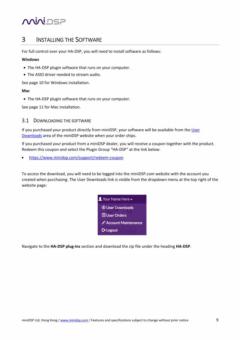
To access the download, you will need to be logged into the miniDSP.com website with the account you
created when purchasing. The User Downloads link is visible from the dropdown menu at the top right of the
website page:
Navigate to the HA‐DSP plug‐ins section and download the zip file under the heading HA‐DSP.

miniDSP Ltd, Hong Kong / www.minidsp.com / Features and specifications subject to change without prior notice 10
3.2 INSTALLATION ON WINDOWS
The miniDSP software installer will automatically download and install additional software that it requires.
You must therefore be connected to the Internet when you run the installer.
3.2.1 Special note for Windows XP and Vista
For Windows XP and Vista, download and install the following frameworks first.
Microsoft .NET framework (version 3.5 or later)
Latest version of Adobe Air
Microsoft Visual C++ 2010 Redistributable Package: for x86 (32‐bit operating system) or x64 (64‐bit
operating system)
Windows XP and Vista also use a different version of the USB driver. Follow the instructions below.
3.2.2 Plugin installation
To install the plugin:
1. Unzip the downloaded software: right‐click on its icon and select “Extract All…”.
2. Navigate to the Windows folder of the unzipped download.
3. Double‐click on the HA‐DSP.exe installer program to run it. We recommend that you accept the default
installation settings.
4. The plugin will start automatically (if you accepted the default installation settings). To make it quicker
to run in future, right‐click on its icon in the taskbar and select “Pin to taskbar.”
3.2.3 USB driver installation
The USB driver is required for the plugin to communicate with the HA‐DSP. It is also required for full audio
streaming functionality.
1. Navigate to the WinDrivers folder of the software download and double‐click on the appropriate
installer (note: the version number embedded in the filename may be different):
miniDSP_UAC2_v2.29.0_ForWinXP_Vista.exe for Windows XP and Vista
miniDSP_UAC2_v4.11.0_2017‐06‐19_setup.exe for Windows 7, 8, and 10
1. We recommend accepting the default installation location. Once the driver installation completes, click
the Finish button.
2. To complete installation of the driver, the HA‐DSP will need to be connected and turned on. You can do
this now, or connect the HA‐DSP later and turn it on to allow Windows to finish the installation.
3.2.4 Additional installation notes
Note 1: The Adobe Air framework may need to connect to the Internet the first time you run the plugin. It’s
strongly recommended that you are connected to the Internet the first time you start the plugin.
Note 2: The first time you run the plugin, you may see a warning from Windows Firewall asking whether the
software should be allowed network access. If you do, ensure that “Private networks...” is checked and
“Public networks...” is not checked. Then click on “Allow access.”

miniDSP Ltd, Hong Kong / www.minidsp.com / Features and specifications subject to change without prior notice 11
3.3 INSTALLATION ON MAC
To install the plugin:
1. Unzip the downloaded software by double‐clicking on the zip file.
2. Navigate to the Mac folder of the unzipped software download.
3. The installer program is named HA‐DSP.pkg. To run it, double‐click on it, or right‐click and open as
described below. We recommend that you accept the default installation settings.
4. To run the plugin, locate HA‐DSP.app in the Applications ‐> miniDSP folder and double‐click on it. To
make it easier to run in future, right‐click on its dock icon and select Options ‐> Keep in Dock.
Note 1: If double‐clicking on an installer brings up a message that the installer cannot run, use this alternate
method (note that the name of the plugin will be HA‐DSP.pkg, not MiniDSP_Plugin.pkg as shown in the
screenshots):
1. Right‐click on the installer (or click while pressing the Control key).
2. On the menu that pops up, move the mouse over the “Open With” item and then click on “Installer
(default).”
3. The following window will appear. Click on “Open.”
Note 2: The Adobe Air framework may need to connect to the Internet the first time you run the plugin. It’s
strongly recommended that you are connected to the Internet the first time you start the plugin.
miniDSP Ltd, Hong Kong / www.minidsp.com / Features and specifications subject to change without prior notice 12
3.4 FIRST‐TIME CONNECTION
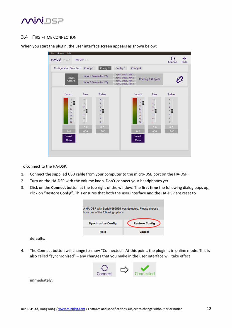
When you start the plugin, the user interface screen appears as shown below:
To connect to the HA‐DSP:
1. Connect the supplied USB cable from your computer to the micro‐USB port on the HA‐DSP.
2. Turn on the HA‐DSP with the volume knob. Don’t connect your headphones yet.
3. Click on the Connect button at the top right of the window. The first time the following dialog pops up,
click on “Restore Config”. This ensures that both the user interface and the HA‐DSP are reset to
defaults.
4. The Connect button will change to show “Connected”. At this point, the plugin is in online mode. This is
also called “synchronized” – any changes that you make in the user interface will take effect
immediately.
miniDSP Ltd, Hong Kong / www.minidsp.com / Features and specifications subject to change without prior notice 13
4 CONNECTIONS
4.1 INPUTS
The HA‐DSP accepts input over USB, analog, or optical digital. For normal operation, the rear panel switch
should be left in position 2.
4.1.1 USB
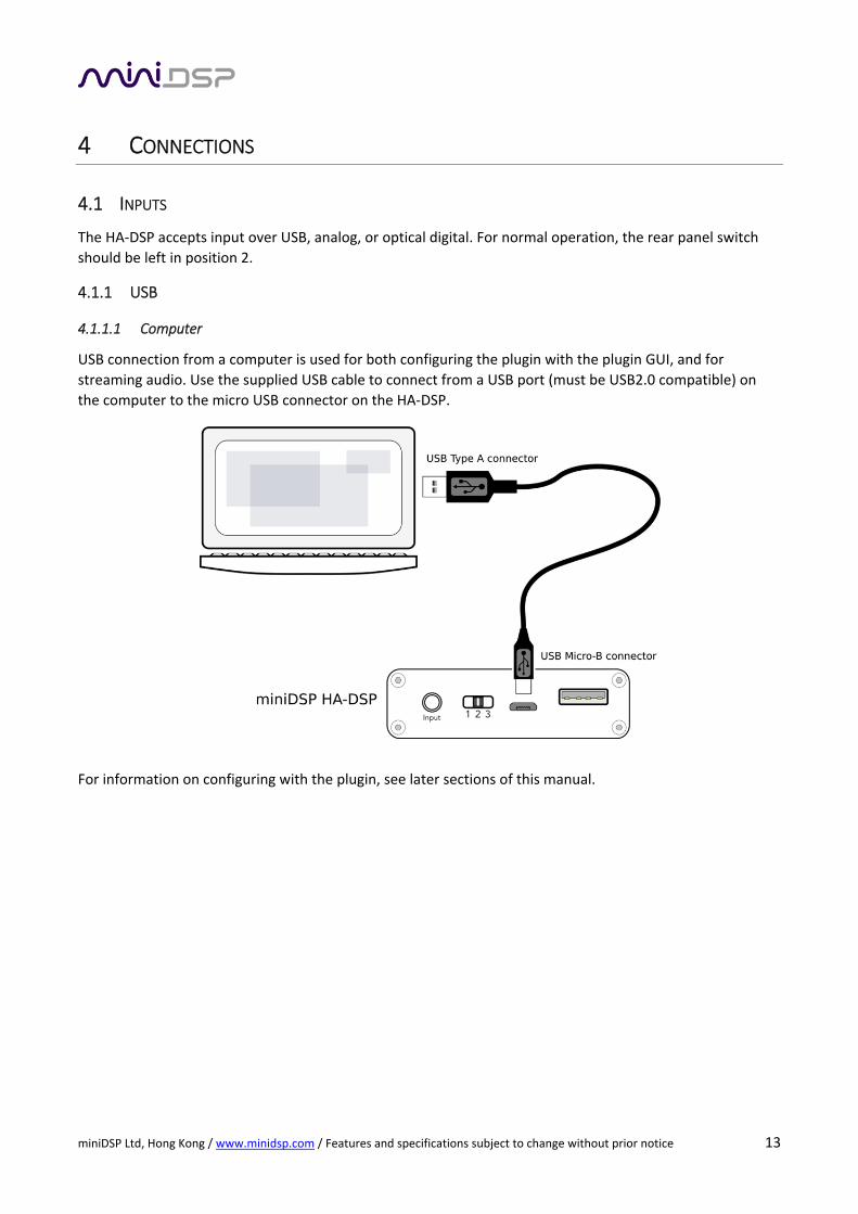
4.1.1.1 Computer
USB connection from a computer is used for both configuring the plugin with the plugin GUI, and for
streaming audio. Use the supplied USB cable to connect from a USB port (must be USB2.0 compatible) on
the computer to the micro USB connector on the HA‐DSP.
For information on configuring with the plugin, see later sections of this manual.

miniDSP Ltd, Hong Kong / www.minidsp.com / Features and specifications subject to change without prior notice 14
4.1.1.2 Android
To connect an Android device to USB, use the
supplied OTG (“on the go”) cable to connect from
your Android device’s micro USB port to the micro
USB port on the HA‐DSP.
Your Android device must support the USB OTG
standard to play audio to the HA‐DSP over USB.
Check the specifications of your device and/or its
user manual. (If your device does not support OTG,
then you can still play audio through the HA‐DSP
using the analog input.)
4.1.1.3 IOS (Apple)
To connect an iOS device (iPhone or iPad) to the HA‐
DSP via USB, use the Apple Camera Connection Kit
(CCK) and the supplied USB type A to micro USB
cable.

miniDSP Ltd, Hong Kong / www.minidsp.com / Features and specifications subject to change without prior notice 15
4.1.2 Digital optical
To connect a digital source, plug a 3.5mm optical connector into the input jack. The HA‐DSP will
automatically detect the optical input and switch to it. USB Audio will be disabled. You can use:
The supplied TOSLINK to mini‐TOSLINK adapter with a regular TOSLINK cable, or
A cable that has a mini‐TOSLINK on the end.
This diagram shows two typical connection examples:

miniDSP Ltd, Hong Kong / www.minidsp.com / Features and specifications subject to change without prior notice 16
4.1.3 Analog
To connect an analog source, plug a 3.5 mm stereo plug into the input jack. The HA‐DSP will automatically
detect the analog input and switch to it. USB Audio will be disabled. You can use:
The supplied 3.5 mm to 3.5 mm cable. This short cable is perfect for connecting to a phone.
Any other stereo cable with a 3.5mm stereo connector. For example, in some cases, the source may have
RCA jacks. In that case, use an RCA to 3.5 mm adapter cable.
This diagram shows two typical connection examples:

miniDSP Ltd, Hong Kong / www.minidsp.com / Features and specifications subject to change without prior notice 17
4.2 OUTPUT
To connect headphones, earbuds, or in‐ear monitors (IEMs), simply plug them into the 3.5mm jack on the
front panel.
If your headphones have a 6.35 mm (1/4‐inch) plug, you will need to use an adapter plug or pigtail.
Turn the volume knob to the lowest position (without necessarily turning off the amplifier) when
inserting the headphone plug.
4.3 TURNING THE AMPLIFIER ON AND OFF
To turn the amplifier on, rotate the knob clockwise. The DSP will take a few seconds to initialize, after which
one of the LEDs (numbered 1 to 4) corresponding to the selected DSP preset will turn on.
To turn the amplifier off, rotate the knob counterclockwise until it clicks and the LEDs are all out.
4.4 FRONT PANEL PRESET CONTROL AND LED STATUS
The HA‐DSP is fitted with a front panel momentary switch to control the active DSP preset. Internal Flash
memory will store up to 4 x DSP preset banks.

miniDSP Ltd, Hong Kong / www.minidsp.com / Features and specifications subject to change without prior notice 18
.
To change to a new preset:
‐ Perform a short press to toggle to the new preset bank
‐ Perform a long press (2sec) to confirm the selection. If a confirmation isn’t performed, the LED will
revert to the currently loaded preset.
LED Status and their meanings:
‐ LED1: Preset1 selected
‐ LED2: Preset2 selected
‐ LED3: Preset3 selected
‐ LED4: Preset4 selected
‐ LED 1&4: Bypass DSP
‐ LED 2&3: DSD mode (automatically selected when playing DSD file)

miniDSP Ltd, Hong Kong / www.minidsp.com / Features and specifications subject to change without prior notice 19
4.5 CHARGING AND POWER
4.5.1 Fast‐charging the HA‐DSP
USB ports supply only limited current. Therefore, while connected to a device such as a computer, the HA‐
DSP will only trickle‐charge. If it is in use at the same time to play audio, it may even continue to drain the
battery.
To charge the HA‐DSP more quickly, connect it to the dedicated 2A USB charger provided along the HA‐DSP.
A USB hub with at least 2A capacity can be used to play audio at the same time as fast charging.
4.5.2 Checking battery level / Upcoming Firmware.
1. Turn the amp off (if it is not already)
2. Press and hold the control button.
3. After a second or two, between 1 and 4 of the LEDs will light up. 1 LED means the battery is very low,
while 4 LEDs means that the battery is fully charged.
4. Turn the amplifier back on if required.

miniDSP Ltd, Hong Kong / www.minidsp.com / Features and specifications subject to change without prior notice 20
5 DSD PLAYBACK MODE
The HA‐DSP detects DSD (Direct Stream Digital) audio sent to it over the USB connection and switches to
play it automatically. When in DSD playback mode, all audio processing except for input selection and final
stage volume is disabled.
5.1 WHAT IS DSD?
DSD is a relatively recent audio format. It is the form in which data is stored in SACDs. (Regular CDs, in
contrast, store data in PCM ‐ pulse code modulation ‐ format.)
DSD audio will be contained in files ending in the suffix “.dsf” or “.dff”. You will be playing DSD only if you
have purposely downloaded DSD files and use a DSD‐capable audio player to play them. Regular audio from
your computer will always be in PCM format. Common audio format such as FLAC, WAV, ALAC, AIFF, and
MP3 are all PCM format.
5.2 HOW DO I PLAY DSD?
By using a DSD‐capable audio player. These days, most audiophile‐level music players are DSD‐aware.
Typically, you will need to tell the player (e.g. in the Preferences settings) that the HA‐DSP can play DSD
using DSD‐over‐PCM (DoP).
5.3 WHY IS AUDIO PROCESSING DISABLED IN DSD PLAYBACK MODE?
The DSD format is not conducive to audio processing. When the HA‐DSP detects DSD audio, it simply
bypasses the digital signal processing (DSP) chip and sends the DSD data directly to the DAC chip.
5.4 WHAT IF I WANT TO KEEP THE PROCESSING WHILE PLAYING DSD FILES?
You will need to tell the player to convert the DSD to PCM before sending it to the HA‐DSP. Some players will
do this automatically if you have not told it to send DSD to the HA‐DSP; others may need a specific setting to
convert to PCM.
5.5 WHY IS IT IMPORTANT THAT I KNOW THAT PROCESSING IS DISABLED IN DSD MODE?
Any EQ or cross‐feed that you have set up in the HA‐DSP will no longer function. In addition, the gain settings
in the input section will (in effect) be set to 0 dB. If you have applied a lot of attenuation here, you will get a
jump in volume when you switch from playing a PCM file to playing a DSD file. Usually, this is not a problem
as the input attenuators are not set very far below zero. You just need to be aware that the volume could
change.
In DSD playback mode, all audio processing is disabled. This may result in a sudden change in
volume.

miniDSP Ltd, Hong Kong / www.minidsp.com / Features and specifications subject to change without prior notice 21
6 INPUT CONTROLS
Channel label
Each input channel is labeled. The label can be changed: to do so, click on it, type a new label (up to
eight characters), and press the Return key.
Level meter, Current RMS level
Displays the current signal level in real time. (The plugin must be in online mode to display signal
levels.)
Gain adjustment
The gain of each channel can be adjusted by moving the Gain Adjustment slider, or by typing the
desired gain into the Current Gain text box. The maximum gain setting is 12 dB and the minimum
gain setting is –72 dB. (0 dB, the default, is unity gain or no change in level.)
Gain adjustment is disabled (along with all other processing) in DSD playback mode. If you have
this set to a low value, be aware that it will effectively be at 0 dB for DSD playback.
Invert
Press this button to mute that channel. The button color and label changes to show that the
channel is inverted.
Mute
Press this button to mute that input channel. The button color and label changes to show that the
channel is muted.

miniDSP Ltd, Hong Kong / www.minidsp.com / Features and specifications subject to change without prior notice 22
7 LINKED MODE
Put the plugin into linked mode by clicking on the linking icon.
In linked mode, the following controls are linked for both channels:
Input gain, invert and mute
Bass and treble settings
Parametric EQ
The FIR filters and the routing matrix are not linked.
Generally, it’s best to start using the plugin in linked mode. When you find a reason to have separate settings
for each channel, at that time you can unlink them. The settings of the two channels after unlinking will
initially be the same.
8 BASS AND TREBLE CONTROLS
The input screen includes bass and treble controls to allow a quick way to
boost the high or low range of the frequency spectrum. Adjust the level of
boost or cut simply by moving the slider. Alternatively, the amount of
boost or cut can be entered directly in the entry box underneath the
slider.
The frequency range over which the controls take effect can be set in the
lower box:
Bass can be adjusted from 200 to 750 Hz. The default is 400 Hz.
Treble can be adjusted from 750 to 300 Hz. The default is 1500 Hz.
The effect of these controls can be viewed on the parametric EQ screen,
by checking the “Overall Response” checkbox.

miniDSP Ltd, Hong Kong / www.minidsp.com / Features and specifications subject to change without prior notice 23
9 PARAMETRIC EQ (PEQ)
Parametric equalization (PEQ) is a flexible type of equalization filter. To open the parametric equalizer
settings window, click on Left Parametric EQ or Right Parametric EQ button. Here is an example window with
one of the preset headphones settings:
If you are in Linked Mode, the graph and the settings apply to both channels. Otherwise, they apply to either
the left or right channel.
9.1 OVERVIEW
There are ten parametric EQ filters on each channel. Click on any of the colored labels EQ1, EQ2 and so on to
select the controls for that filter. The graph in orange represents the frequency response of all filters
combined. If the button “Overall Response” is checked, this also includes the effect of the Bass and Treble
controls in the Input Control block.
You can hover the mouse over the orange curve to bring up an overlay showing
the frequency and the corresponding gain:
PEQs are specified either in Basic mode or Advanced mode. For Advanced mode, see page 31.
To disable an individual filter, click on the Bypass button at the lower right. The filter is enabled if the button
says “BYPASS” and disabled if the button says “BYPASSED”:
9.2 TYPES OF FILTER

miniDSP Ltd, Hong Kong / www.minidsp.com / Features and specifications subject to change without prior notice 24
There are four types of filter. This is selected towards the lower right of the settings window:
9.2.1 PEAK
This filter creates a dip or a peak in the frequency response. These two examples show how the parameters
affect the response:
9.2.2 LOW_SHELF and HIGH_SHELF
This filter reduces or increases part of the frequency spectrum. The Frequency parameter is the frequency
where the response has half the value given by Gain (for example, if Gain is 10, then at Frequency Hz the
gain is 5 dB). These two examples show how the parameters affect the response:
9.2.3 ALL_PASS
This filter creates a varying phase shift across the frequency band, with the specified frequency being the
frequency where half the total phase shift occurs. This filter will have no effect on the displayed graph. This
should be considered an advanced option that will not be of use to 99% of users.
miniDSP Ltd, Hong Kong / www.minidsp.com / Features and specifications subject to change without prior notice 25
10 CONFIGURATION PRESETS
The complete set of data that controls the DSP processor is called a configuration. This includes input levels,
bass and treble controls, parametric EQ, FIR filtering and the routing matrix. It does not include the volume
set by the front panel knob.
Four configurations are stored onboard in the HA‐DSP. By default, these are all set to “straight‐through”
processing.
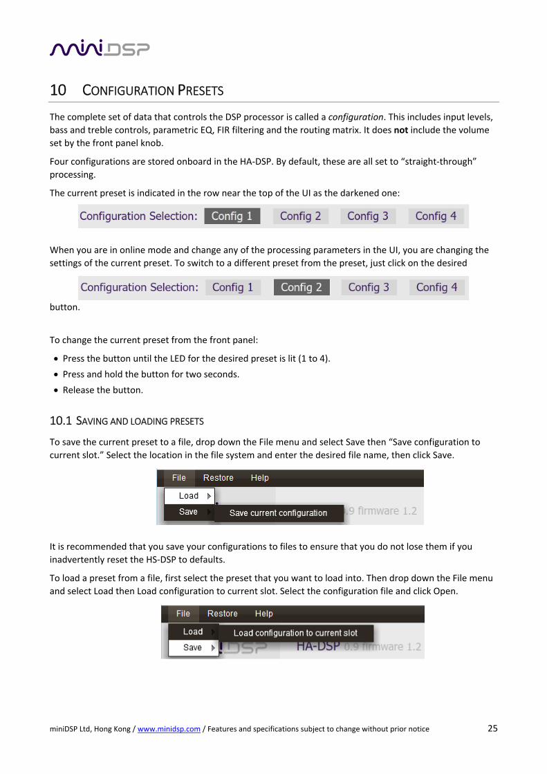
The current preset is indicated in the row near the top of the UI as the darkened one:
When you are in online mode and change any of the processing parameters in the UI, you are changing the
settings of the current preset. To switch to a different preset from the preset, just click on the desired
button.
To change the current preset from the front panel:
Press the button until the LED for the desired preset is lit (1 to 4).
Press and hold the button for two seconds.
Release the button.
10.1 SAVING AND LOADING PRESETS
To save the current preset to a file, drop down the File menu and select Save then “Save configuration to
current slot.” Select the location in the file system and enter the desired file name, then click Save.
It is recommended that you save your configurations to files to ensure that you do not lose them if you
inadvertently reset the HS‐DSP to defaults.
To load a preset from a file, first select the preset that you want to load into. Then drop down the File menu
and select Load then Load configuration to current slot. Select the configuration file and click Open.
miniDSP Ltd, Hong Kong / www.minidsp.com / Features and specifications subject to change without prior notice 26
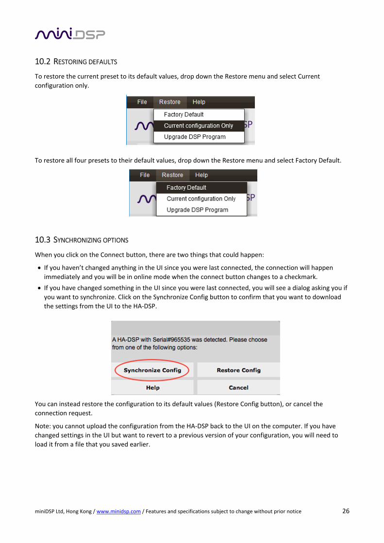
10.2 RESTORING DEFAULTS
To restore the current preset to its default values, drop down the Restore menu and select Current
configuration only.
To restore all four presets to their default values, drop down the Restore menu and select Factory Default.
10.3 SYNCHRONIZING OPTIONS
When you click on the Connect button, there are two things that could happen:
If you haven’t changed anything in the UI since you were last connected, the connection will happen immediately and you will be in online mode when the connect button changes to a checkmark.
If you have changed something in the UI since you were last connected, you will see a dialog asking you if
you want to synchronize. Click on the Synchronize Config button to confirm that you want to download
the settings from the UI to the HA‐DSP.
You can instead restore the configuration to its default values (Restore Config button), or cancel the
connection request.
Note: you cannot upload the configuration from the HA‐DSP back to the UI on the computer. If you have
changed settings in the UI but want to revert to a previous version of your configuration, you will need to
load it from a file that you saved earlier.
miniDSP Ltd, Hong Kong / www.minidsp.com / Features and specifications subject to change without prior notice 27
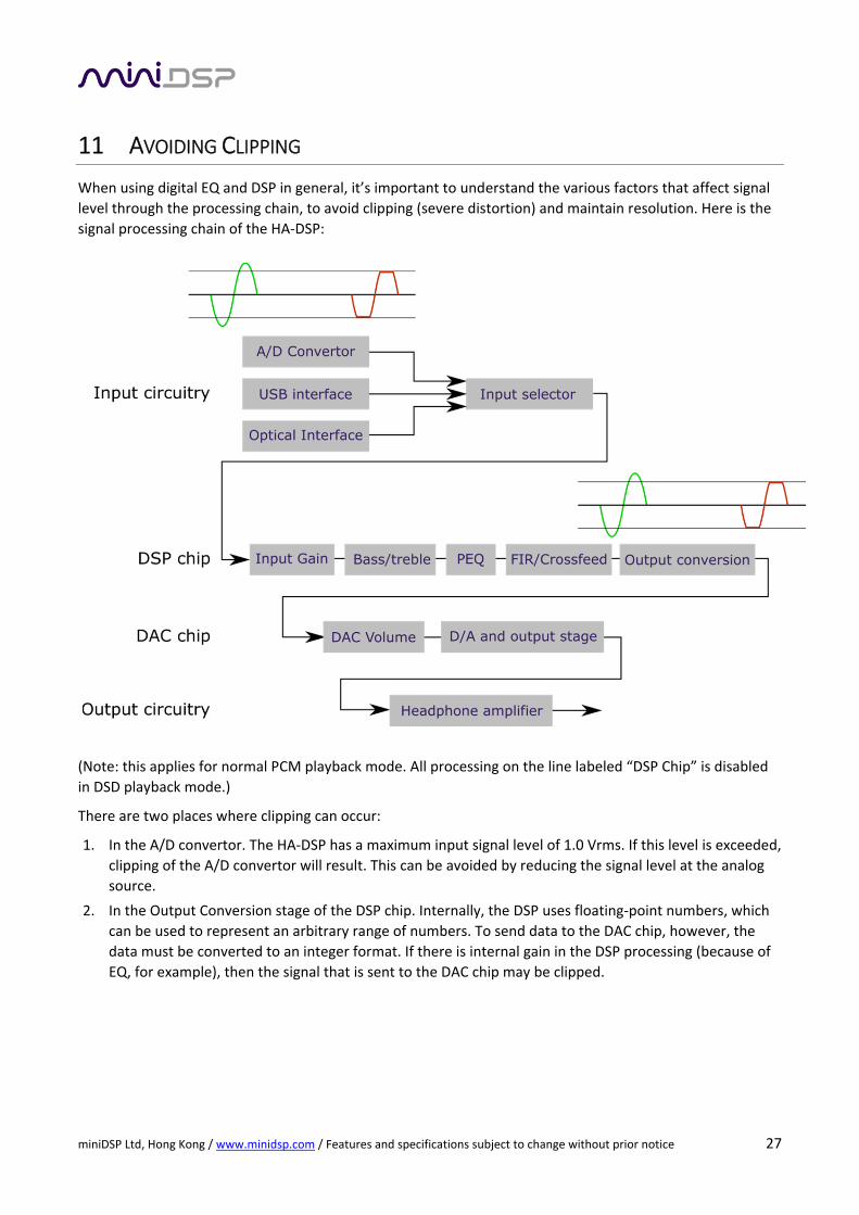
11 AVOIDING CLIPPING
When using digital EQ and DSP in general, it’s important to understand the various factors that affect signal
level through the processing chain, to avoid clipping (severe distortion) and maintain resolution. Here is the
signal processing chain of the HA‐DSP:
(Note: this applies for normal PCM playback mode. All processing on the line labeled “DSP Chip” is disabled
in DSD playback mode.)
There are two places where clipping can occur:
1. In the A/D convertor. The HA‐DSP has a maximum input signal level of 1.0 Vrms. If this level is exceeded,
clipping of the A/D convertor will result. This can be avoided by reducing the signal level at the analog
source.
2. In the Output Conversion stage of the DSP chip. Internally, the DSP uses floating‐point numbers, which
can be used to represent an arbitrary range of numbers. To send data to the DAC chip, however, the
data must be converted to an integer format. If there is internal gain in the DSP processing (because of
EQ, for example), then the signal that is sent to the DAC chip may be clipped.
miniDSP Ltd, Hong Kong / www.minidsp.com / Features and specifications subject to change without prior notice 28
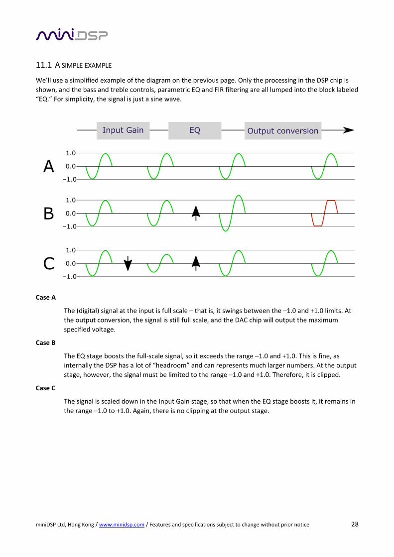
11.1 A SIMPLE EXAMPLE
We’ll use a simplified example of the diagram on the previous page. Only the processing in the DSP chip is
shown, and the bass and treble controls, parametric EQ and FIR filtering are all lumped into the block labeled
“EQ.” For simplicity, the signal is just a sine wave.
Case A
The (digital) signal at the input is full scale – that is, it swings between the –1.0 and +1.0 limits. At
the output conversion, the signal is still full scale, and the DAC chip will output the maximum
specified voltage.
Case B
The EQ stage boosts the full‐scale signal, so it exceeds the range –1.0 and +1.0. This is fine, as
internally the DSP has a lot of “headroom” and can represents much larger numbers. At the output
stage, however, the signal must be limited to the range –1.0 and +1.0. Therefore, it is clipped.
Case C
The signal is scaled down in the Input Gain stage, so that when the EQ stage boosts it, it remains in
the range –1.0 to +1.0. Again, there is no clipping at the output stage.

miniDSP Ltd, Hong Kong / www.minidsp.com / Features and specifications subject to change without prior notice 29
11.2 A MORE REALISTIC EXAMPLE
In practice, the HA‐DSP is processing a signal with a spread of frequencies, all changing rapidly in level.
Consider the example EQ shown on page 23.
With the default unity gain through all DSP processing blocks, this filter will result in clipping on music with a
lot of bass content. Assuming this is the only processing (i.e. no bass or treble boost and no FIR filters), we
could take two approaches.
Ultra‐conservative
Set either Input Gain or Master Volume to ‐9 dB. This will ensure that no digital input signal (that
isn’t already clipped) will clip at the output stage. (This approach will always be required in certain
situations such as when running full‐scale test signals through the HA‐DSP.)
Conservative
Set either Input Gain or Master Volume to ‐6 dB. Since there is typically a lot of energy in the bass
region, this will ensure that low frequencies do not cause clipping. The 9 dB peak at 2800 Hz is
unlikely to cause clipping with music, as the rest of the spectrum is generally well below this.
In the case where you are using additional EQ, such as Bass or Treble boost, you will need make sure that
you click on the Overall Response checkbox to assess the total amount of gain.

miniDSP Ltd, Hong Kong / www.minidsp.com / Features and specifications subject to change without prior notice 30
11.3 THE “NO GAIN” APPROACH
An alternative approach to setting input gain is ensuring that your EQ curve is “mostly below zero.”
In one common case where a low‐shelf filter is used as a bass boost, the filter can be reversed:
Change it to a high‐shelf filter.
Set the gain negative instead of positive.
For example, on page 23 the filter shown is a low shelf with gain of 5.9 dB. Here is the same filter reversed as
described above:
Note that the whole graph is now shifted down.
A second approach is to use advanced mode of the parametric EQ. Set an unused filter to Advanced mode.
To reduce the gain by 6 dB, set coefficient b0 to 0.5, then press the Process button.
For each halving of b0, the gain of the whole PEQ block is reduced by 6 dB. So use the value 0.25 for a 12 dB
reduction in level.

miniDSP Ltd, Hong Kong / www.minidsp.com / Features and specifications subject to change without prior notice 31
12 ADVANCED TOPICS
The functions in this section are for advanced users and headphone EQ developers.
12.1 PEQ ADVANCED MODE
The parametric EQ can use Advanced mode, which allows you to allow you to directly provide the low‐level
parameters aka biquad coefficients that control the digital filters of the processor. This allows you to load
other types of parametric filters or to import a complete correction file generated by other software.
Each PEQ filter has a selector that switches it to advanced mode:
12.1.1 What’s a “biquad?
A biquad is the basic unit of processing that is used to create digital filters. It can be described either with an
equation or with a signal flow diagram, as shown here:
A single biquad like this can perform a great many functions, including all of the functions of a single
parametric EQ filter, one 6 or 12 dB/octave high pass or low pass filter, and more. Biquads are combined in
series (cascaded) to create more complex filters. The function that each biquad performs is determined by
just five numbers: a1, a2, a0, b1, and b2. These numbers are called the coefficients.
12.1.2 Advanced mode for a single filter
To change a single filter, switch it to Advanced mode:
Paste in the desired coefficients, then click on the Process button for them to take effect:
miniDSP Ltd, Hong Kong / www.minidsp.com / Features and specifications subject to change without prior notice 32
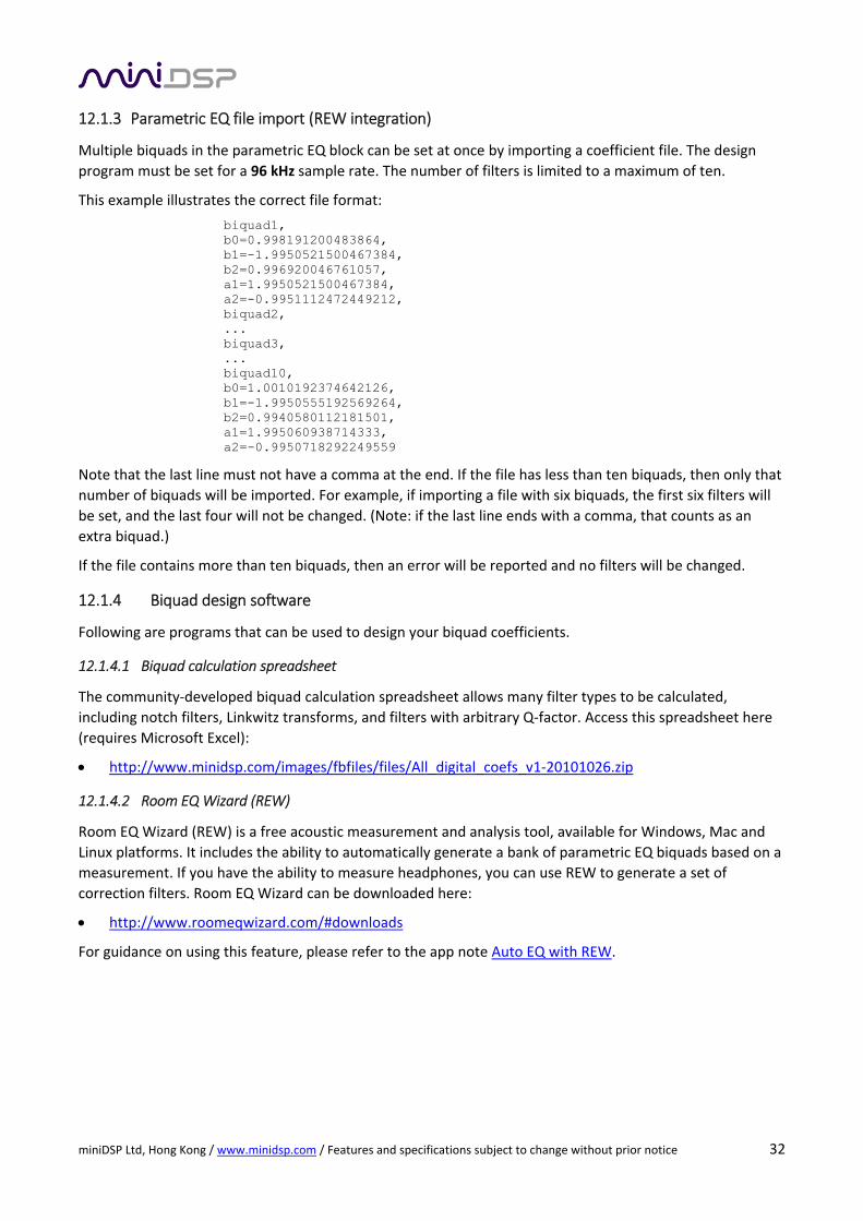
12.1.3 Parametric EQ file import (REW integration)
Multiple biquads in the parametric EQ block can be set at once by importing a coefficient file. The design
program must be set for a 96 kHz sample rate. The number of filters is limited to a maximum of ten.
This example illustrates the correct file format:
biquad1, b0=0.998191200483864, b1=-1.9950521500467384, b2=0.996920046761057, a1=1.9950521500467384, a2=-0.9951112472449212, biquad2, ... biquad3, ... biquad10, b0=1.0010192374642126, b1=-1.9950555192569264, b2=0.9940580112181501, a1=1.995060938714333, a2=-0.9950718292249559
Note that the last line must not have a comma at the end. If the file has less than ten biquads, then only that
number of biquads will be imported. For example, if importing a file with six biquads, the first six filters will
be set, and the last four will not be changed. (Note: if the last line ends with a comma, that counts as an
extra biquad.)
If the file contains more than ten biquads, then an error will be reported and no filters will be changed.
12.1.4 Biquad design software
Following are programs that can be used to design your biquad coefficients.
12.1.4.1 Biquad calculation spreadsheet
The community‐developed biquad calculation spreadsheet allows many filter types to be calculated,
including notch filters, Linkwitz transforms, and filters with arbitrary Q‐factor. Access this spreadsheet here
(requires Microsoft Excel):
http://www.minidsp.com/images/fbfiles/files/All_digital_coefs_v1‐20101026.zip
12.1.4.2 Room EQ Wizard (REW)
Room EQ Wizard (REW) is a free acoustic measurement and analysis tool, available for Windows, Mac and
Linux platforms. It includes the ability to automatically generate a bank of parametric EQ biquads based on a
measurement. If you have the ability to measure headphones, you can use REW to generate a set of
correction filters. Room EQ Wizard can be downloaded here:
http://www.roomeqwizard.com/#downloads
For guidance on using this feature, please refer to the app note Auto EQ with REW.

miniDSP Ltd, Hong Kong / www.minidsp.com / Features and specifications subject to change without prior notice 33
12.2 FIR FILTERING AND ROUTING
FIR filtering is a powerful and advanced feature of the HA‐DSP. It allows construction of complex arbitrary
equalization and crossover filters with independent control of amplitude and phase. The parameters of each
FIR filter are set in the FIR settings window:
Browse Opens a file browser to select a file containing FIR filter coefficients. (See Filter file format below).
Unload FIR Deletes the currently loaded filter from the display and from the DSP memory.
Send to DSP Writes the currently loaded filter into the DSP memory.
BYPASS Disables the FIR filter. The filter is disabled when the button is "lit."
File Mode / Manual Mode
In File Mode, the window displays the Browse and Unload FIR buttons as shown above. In Manual
Mode, the display changes to allow direct text entry of the FIR filter coefficients, as shown below.
The coefficients can be pasted into the window from a text editor.

miniDSP Ltd, Hong Kong / www.minidsp.com / Features and specifications subject to change without prior notice 34
12.2.1 FIR filtering overview
FIR ("finite impulse response") filtering differs from the IIR ("infinite impulse response") filters used in the
PEQ and crossover blocks. Technically speaking, IIR filters are recursive, meaning that each output value is
partially calculated from earlier output values as well as from input values. An FIR filter is specified by a large
array of numbers, whereas an IIR filter requires only a fairly small of values to be specified.
These numbers are conventionally referred to as "taps." The HA‐DSP can compute a total of 7168 taps.
These taps can be distributed as you wish across the four FIR blocks on the output, with the limitation that
each output channel must have 6 or more taps and can have no more than 4096 taps. The decision on how
many taps to allocate to each channel up to you, and should be determined after working with an FIR filter
design program (see below). The number of taps is set in the lower right corner (click on the text entry box
and type the desired number of taps, then press Tab or Return):
12.2.2 FIR filter design software
The filter coefficients must be created with the aid of filter design software. miniDSP does not provide any
such software, instead referring you to the many software packages available for this purpose (both
freeware and commercial). Please see the FIR filter tools page on our website.
12.2.3 Filter file format
The filter coefficient file loaded in File Mode uses IEEE 754 single‐precision binary floating‐point format. The
number of entries in the file must not exceed the allocated number of taps. Make sure to select the correct
sample rate frequency of the plugin.
In Manual Mode, the coefficients must be plain text in this format:
b0 = 1, b1 = ‐1, b2 = 0.5, b3 = ‐0.5, b4 = 0.2, b5 = 1,
miniDSP Ltd, Hong Kong / www.minidsp.com / Features and specifications subject to change without prior notice 35
12.2.4 Loading filter coefficients
In File Mode:
5. Click Browse, navigate to the file containing the filter coefficients, and open it. A dialog will appear
confirming the number of coefficients loaded.
6. Confirm that the response curve is as you expect.
7. Press Send to DSP. This will write the coefficients into the DSP's memory.
8. To clear the filter coefficients, click Unload FIR and then Send to DSP.
In Manual Mode:
9. Cut and paste the coefficients from the text output of the design program.
10. Press the Process button.
11. Confirm that the frequency response graph is as you expect.
12. Press Send to DSP. This will write the coefficients into the DSP's memory.
13. To clear the filter coefficients, click Clear Taps and then Send to DSP.
If, after selecting a filter file or setting coefficients, the frequency response graph does not change
as expected, make sure that the Bypass button is turned off.
If you clear the filter taps, make sure that you also bypass the filter, otherwise there will be no
audio through that channel.
12.2.5 Routing section
The Routing matrix mixer is used to direct input channels (Rows) to output channels (Columns). To turn on
routing for a crosspoint, click on that crosspoint. The display will change from “Off” to show the mix level (0
dB by default).
The matrix mixer makes the HA‐DSP adaptable to many audio processing situations. At each cross‐point, the
gain of the signal being mixed can be adjusted to a value between ‐72 and +12 dB. To adjust the gain, right‐
click on the crosspoint and a gain control will appear. Adjust the gain with the slider, or by typing in the value
directly, then click close. You can also Invert the polarity at a crosspoint (e.g. L‐R). the crosspoint gain value
will turn green to indicate an inverted state.

miniDSP Ltd, Hong Kong / www.minidsp.com / Features and specifications subject to change without prior notice 36
Further information will shortly be added on use case examples for FIR blocks + Routing matrix.

miniDSP Ltd, Hong Kong / www.minidsp.com / Features and specifications subject to change without prior notice 37
13 SPECIFICATIONS
(*) DSP processor is disabled in DSD playback mode.
Computer configuration Driverless USB 2.0 control interface for Windows and Mac OS X
Chip complement XMOS xCore‐200 processor, ESS Sabre ES9018K2M DAC, Analog Devices ADSP‐
21489 400 MHz floating‐point SHARC DSP, AKM5386 ADC
Audio resolution 24‐bit input, sample rate depends on loaded plugin.
USB Audio input PCM: up to 32‐bit input, sample rates from 44.1 to 192 kHz on PC/Mac, PCM up
to 96 kHz on select Android devices.
DSD: DSD64 and DSD128 (normal and double‐rate)*
Digital audio input Mini‐TOSLINK optical connector. 16‐ or 24‐bit, sample rates from 44.1 to 192
kHz.
Analog audio input Maximum input level: 1.0 Vrms.
Signal‐to‐noise ratio: Up to 100 dB
Analog audio output Frequency response: 20 Hz to 20 kHz +/‐ 0.2 dB.
Signal‐to‐noise ratio: 112 dB (32 Ω load, 1 kHz, A‐weighted, digital in 0 dB)
THD+N: 0.001% (32 Ω, 1 kHz, 65 mW + 65 mW, mid gain)
Supported headphone impedance: 16 – 600 Ω
Maximum power output: 100 mW + 100 mW (32 Ω, 1 kHz, digital in 0 dB)
Storage/presets
All settings controllable in real time from software user interface.
Up to 4 presets stored in local flash memory.
Battery Lithium Ion 3300 mAh / Up to 10 hours of continuous playback time
Charging 5V 2A (fast charge) USB charger provided
Dimensions (H x W x D) 20 x 69 x 137 mm
Weight 230 g

miniDSP Ltd, Hong Kong / www.minidsp.com / Features and specifications subject to change without prior notice 38
13.1 FIRMWARE UPGRADE
miniDSP may occasionally provide an upgrade to the HA‐DSP MCU firmware to enable new features. To
upgrade the MCU firmware, first download and install the latest version of the HA‐DSP plugin from the User
Downloads section of the miniDSP website.
DO NOT DISCONNECT THE USB CABLE OR POWER FROM THE HA‐DSP WHILE FIRMWARE UPGRADE
IS IN PROGRESS. DOING SO MAY “BRICK” YOUR HA‐DSP
13.1.1 Windows
1. Connect the HA‐DSP to your computer via USB (if not already connected) and power it on.
2. Start the miniDSP UAC2 DFU Tool.
3. The upgrade program will start:

miniDSP Ltd, Hong Kong / www.minidsp.com / Features and specifications subject to change without prior notice 39
4. Click on the Browse button, navigate to the folder XMOS_Firmware in the plugin download folder, and
select the firmware file. It will have a name like “HA‐DSP_vx.xx.bin.” (The version number may be
different.)
5. Click on the Start button.
6. You will get a progress bar as upgrade proceeds:
7. Once the firmware upgrade completes, you will see a message that the upgrade completed
successfully:
8. Click on Exit.
9. That’s it! You’re done. You can now use your 2x4 HD with the new functionality.
miniDSP Ltd, Hong Kong / www.minidsp.com / Features and specifications subject to change without prior notice 40
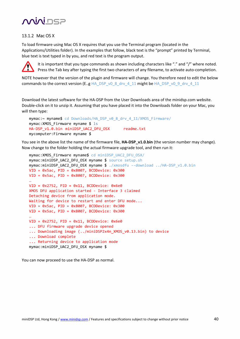
13.1.2 Mac OS X
To load firmware using Mac OS X requires that you use the Terminal program (located in the
Applications/Utilities folder). In the examples that follow, black text is the “prompt” printed by Terminal,
blue text is text typed in by you, and red text is the program output.
It is important that you type commands as shown including characters like “.” and “/” where noted.
Press the Tab key after typing the first two characters of any filename, to activate auto‐completion.
NOTE however that the version of the plugin and firmware will change. You therefore need to edit the below
commands to the correct version (E..g HA_DSP_v0_8_drv_4_11 might be HA_DSP_v0_9_drv_4_11
Download the latest software for the HA‐DSP from the User Downloads area of the minidsp.com website.
Double‐click on it to unzip it. Assuming that you have placed it into the Downloads folder on your Mac, you
will then type:
mymac:~ myname$ cd Downloads/HA_DSP_v0_8_drv_4_11/XMOS_Firmware/
mymac:XMOS_Firmware myname $ ls
HA‐DSP_v1.0.bin miniDSP_UAC2_DFU_OSX readme.txt
mycomputer:Firmware myname $
You see in the above list the name of the firmware file, HA‐DSP_v1.0.bin (the version number may change).
Now change to the folder holding the actual firmware upgrade tool, and then run it:
mymac:XMOS_Firmware myname$ cd miniDSP_UAC2_DFU_OSX/
mymac:miniDSP_UAC2_DFU_OSX myname $ source setup.sh
mymac:miniDSP_UAC2_DFU_OSX myname $ ./xmosdfu ‐‐download ../HA‐DSP_v1.0.bin
VID = 0x5ac, PID = 0x8007, BCDDevice: 0x300
VID = 0x5ac, PID = 0x8007, BCDDevice: 0x300
…
VID = 0x2752, PID = 0x11, BCDDevice: 0x6e0
XMOS DFU application started ‐ Interface 3 claimed
Detaching device from application mode.
Waiting for device to restart and enter DFU mode...
VID = 0x5ac, PID = 0x8007, BCDDevice: 0x300
VID = 0x5ac, PID = 0x8007, BCDDevice: 0x300
…
VID = 0x2752, PID = 0x11, BCDDevice: 0x6e0
... DFU firmware upgrade device opened
... Downloading image (../miniDSP2x4n_XMOS_v0.13.bin) to device
... Download complete
... Returning device to application mode
mymac:miniDSP_UAC2_DFU_OSX myname $
You can now proceed to use the HA‐DSP as normal.