half-reentrant cavity design, fabrication, and testing ... · lower bpk/eacc by making cavity...
TRANSCRIPT
Half-Reentrant CavityDesign, Fabrication, and Testing
Mandi Meidlinger
Michigan State UniversityNational Superconducting Cyclotron Laboratory
East Lansing, Michigan, USA
October 17, 200713th International Workshop on RF Superconductivity
Peking UniversityBeijing, China
2
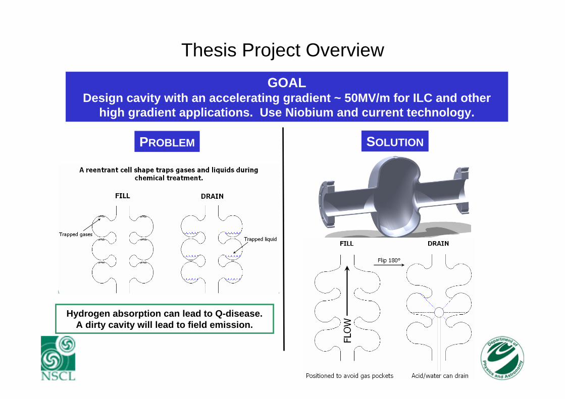
Thesis Project OverviewGOAL
Design cavity with an accelerating gradient ~ 50MV/m for ILC and other high gradient applications. Use Niobium and current technology.
Hydrogen absorption can lead to Q-disease.A dirty cavity will lead to field emission.
PROBLEM SOLUTION

3
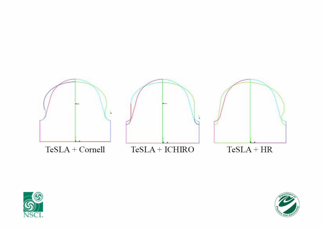
Three Proposed Cell Shapes for the ILC
ICHIRO Low-Loss Shape Cornell Reentrant Shape Half-Reentrant Shape
First developed for JLAB upgrade to stay within cryogenic capabilities
Eacc=52 MV/m
Eacc=51.4 MV/m
Simulated Eacc=50.8 MV/m.
Relative to TeSLA GeometryBpk decreases approx. 10%Epk increases approx. 20%
4
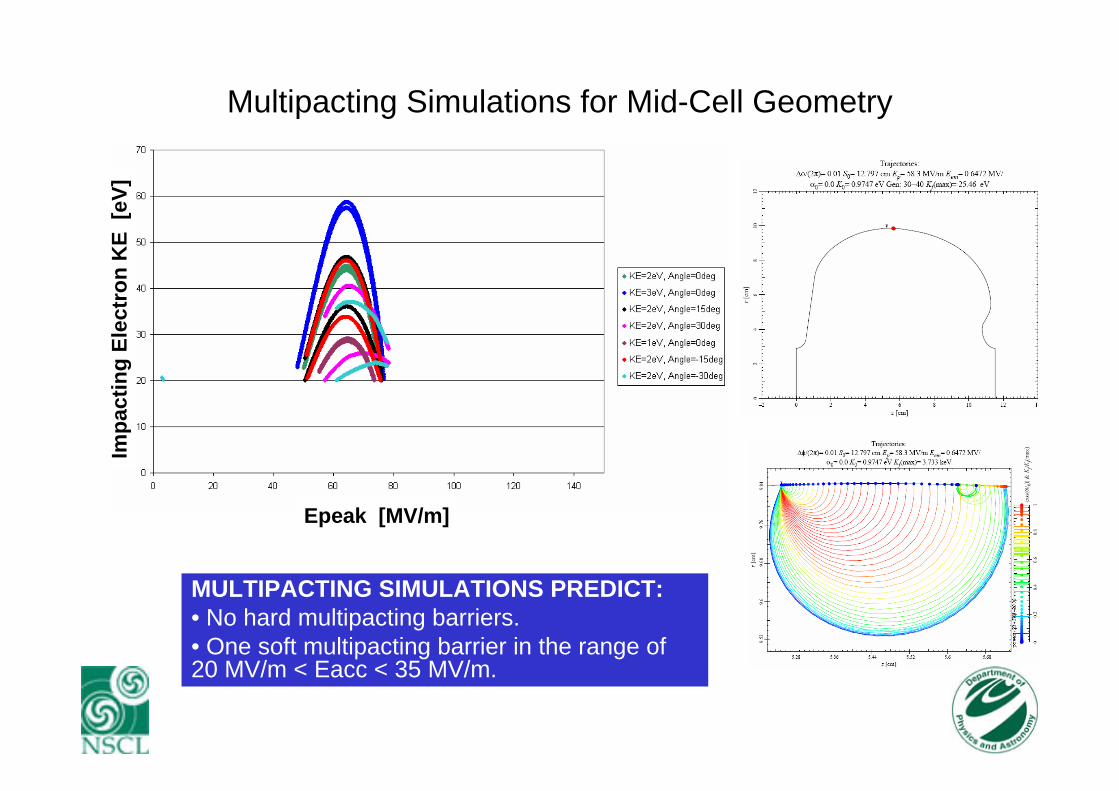
Multipacting Simulations for Mid-Cell Geometry
MULTIPACTING SIMULATIONS PREDICT:• No hard multipacting barriers.• One soft multipacting barrier in the range of 20 MV/m < Eacc < 35 MV/m.
Epeak [MV/m]
Impa
ctin
g El
ectr
on K
E[e
V]
5
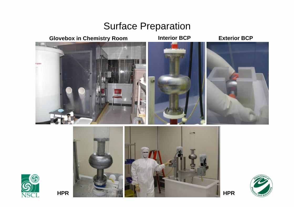
Surface PreparationGlovebox in Chemistry Room Interior BCP Exterior BCP
HPR HPR
6
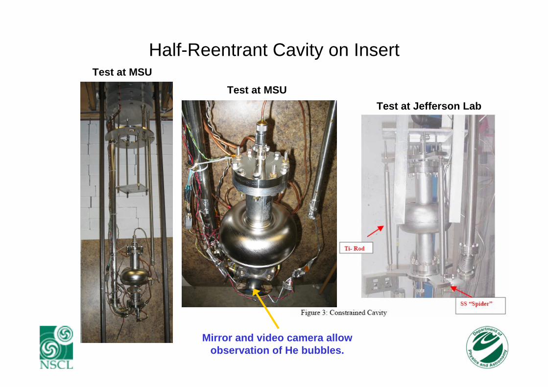
Half-Reentrant Cavity on InsertTest at MSU
Test at MSUTest at Jefferson Lab
Mirror and video camera allow observation of He bubbles.
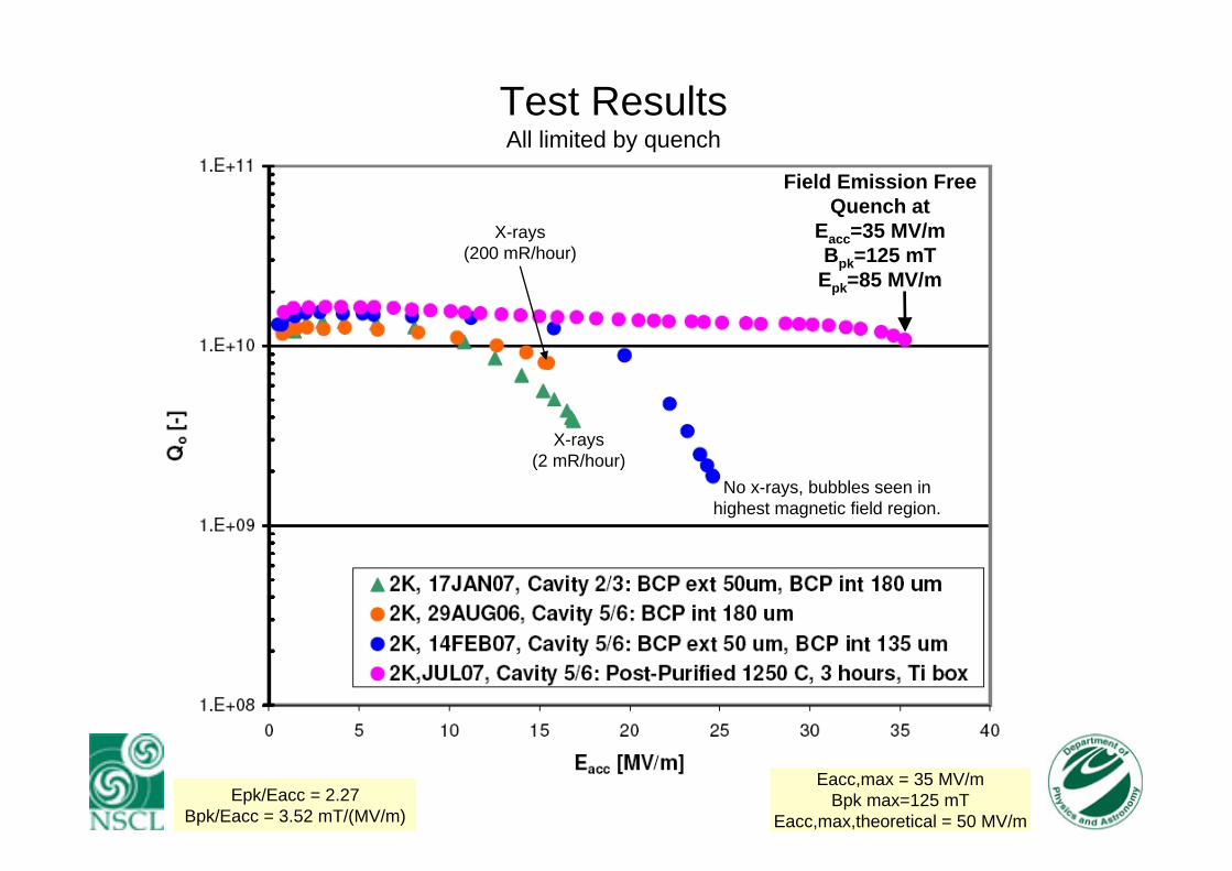
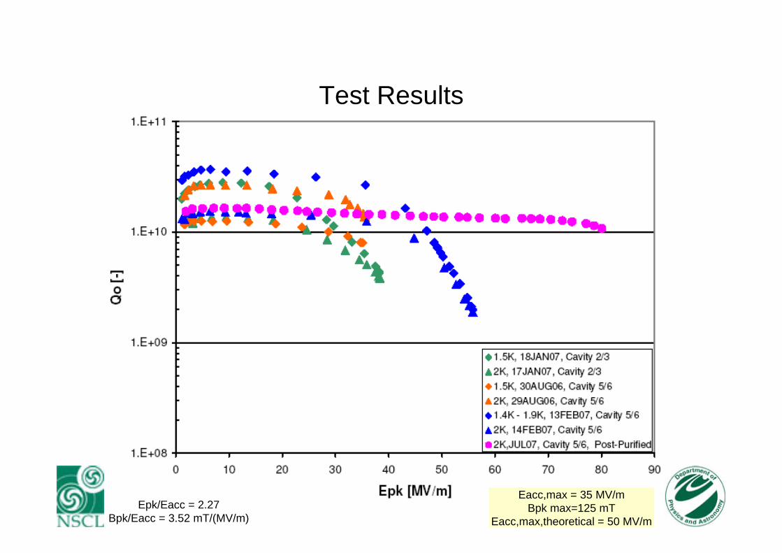
7Epk/Eacc = 2.27Bpk/Eacc = 3.52 mT/(MV/m)
Eacc,max = 35 MV/mBpk max=125 mT
Eacc,max,theoretical = 50 MV/m
Test ResultsAll limited by quench
Field Emission FreeQuench at
Eacc=35 MV/mBpk=125 mT
Epk=85 MV/m
No x-rays, bubbles seen in highest magnetic field region.
X-rays(2 mR/hour)
X-rays(200 mR/hour)
8
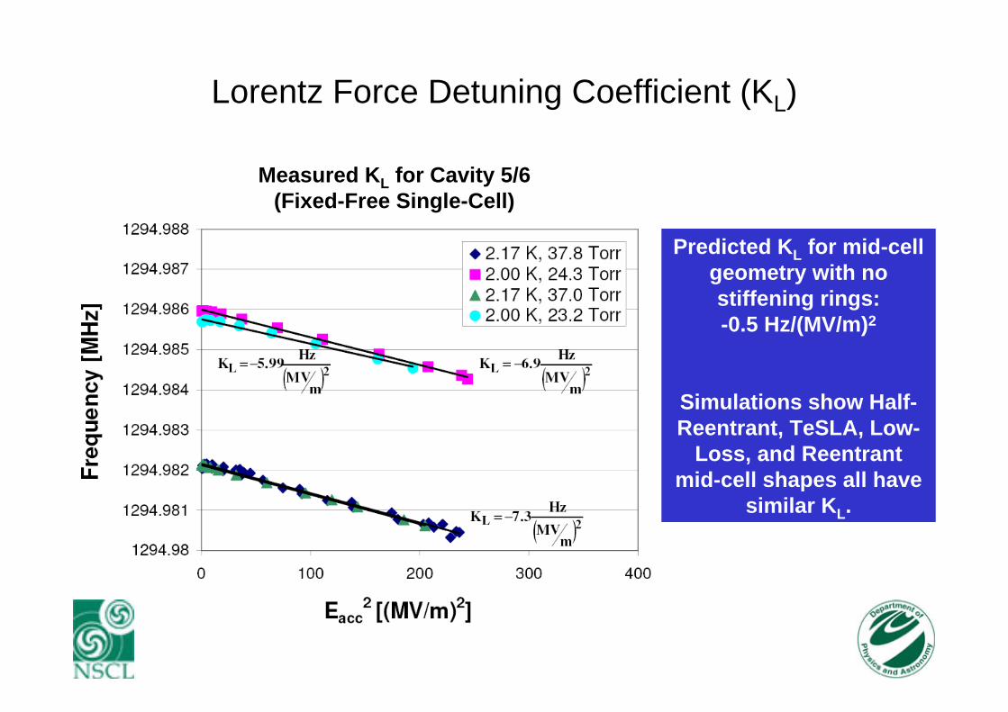
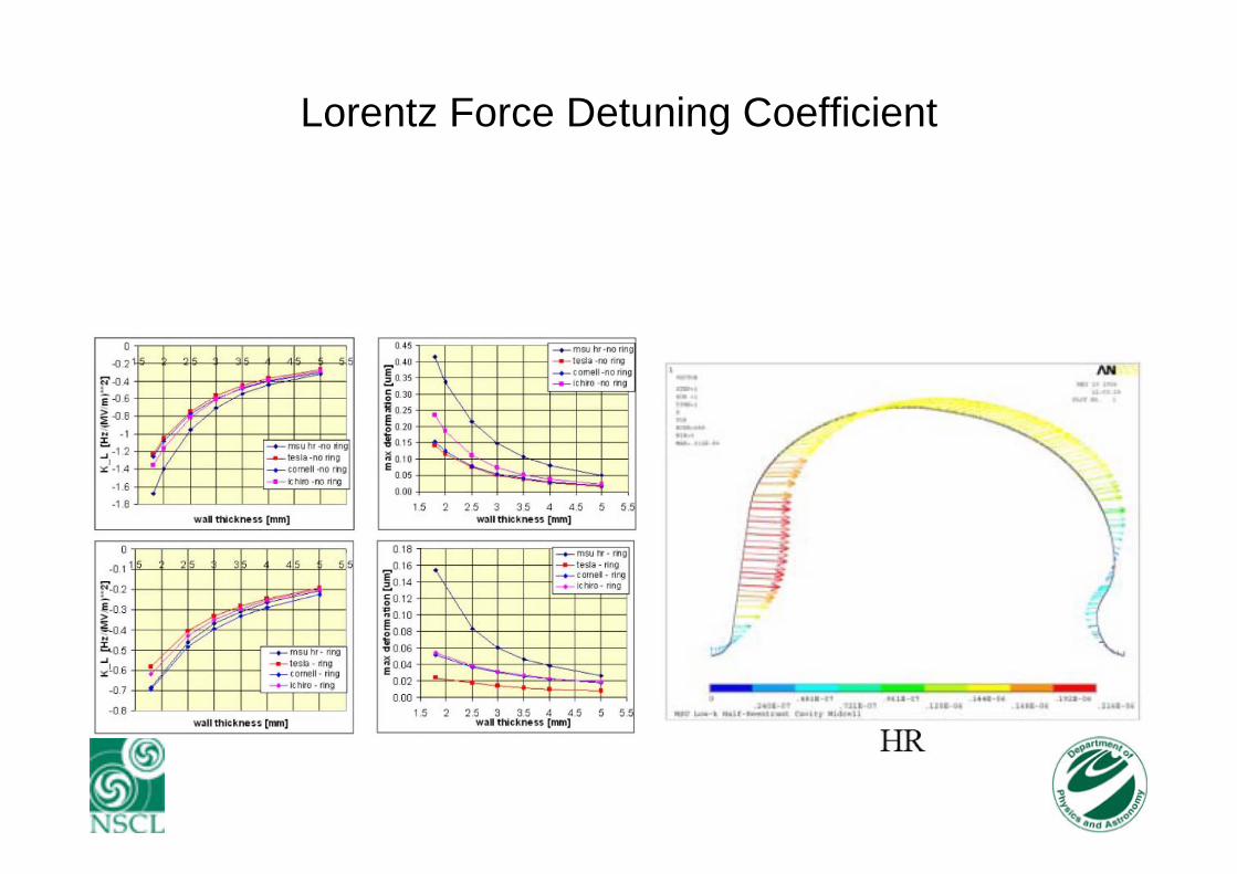
Lorentz Force Detuning Coefficient (KL)
Predicted KL for mid-cell geometry with no stiffening rings: -0.5 Hz/(MV/m)2
Simulations show Half-Reentrant, TeSLA, Low-
Loss, and Reentrant mid-cell shapes all have
similar KL.
Measured KL for Cavity 5/6(Fixed-Free Single-Cell)

9
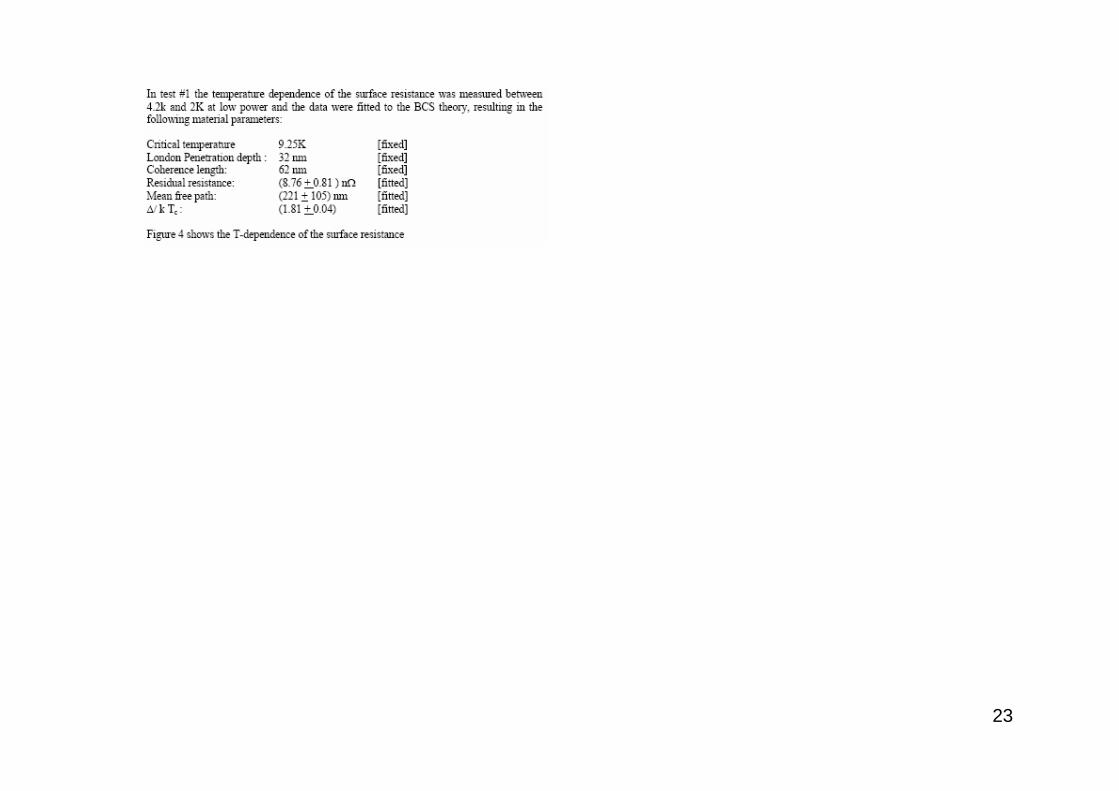
Surface Resistance

10
Conclusion of Test Results
• Reached Eacc~25 MV/m for second test of cavity 5/6.• Accelerating gradient reached is consistent with comparable
cavities with similar surface treatment (i.e. BCP followed by HPR).
• Cavity 5/6 reached Eacc=35 MV/m after post-purification. This is consistent with other BCP/post-purified cavities.
• No multipacting barrier seen, consistent with predictions.• Next steps would be:
– Outside etch of post-purified cavity to remove Ti layer.– Electropolish followed by bakeout.
• Anticipate higher gradients will be reached.• Currently no reason to suspect half-reentrant single-cell cavity
cannot achieve design gradient of 50 MV/m.
11
Acknowledgements
John Bierwagen, Steve Bricker, Chris Compton, Terry L. Grimm, Walter Hartung, Matthew Johnson, John
Popielarski, Laura Saxton, Richard York(NSCL, East Lansing, Michigan)
Peter Kneisel (Jefferson Laboratory)
Evgeny Zaplatin (Forschungszentrum Juelich)
Thank You to:Walter Hartung for thesis guidance.Rongli Geng for cavity fabrication discussions.Hasan Padamsee for cavity testing discussions.

12
Deep Drawing and Electron Beam Welding
Regular two-step process: each half-cell
pressed with75 tons followed by
coining dies pressed with 17 tons.
Vent holes were drilled in the
reentrant region for both the female and male dies to allow
lubrication to escape during
stamping.
Full penetration equator weldwas performed from the outside through 2 mm thick niobium.
13
Lorentz Force Detuning Coefficient

14
Thesis Project OverviewGOAL
Design cavity with an accelerating gradient ~ 50MV/m for ILC and other high gradient applications. Use Niobium and current technology.
DesignNumerical solution
of Maxwell’sequations
Fabrication1 Cu prototype,
2 single-cellNb Cavities
TestingTest single-cell
Nb cavity at 4.2Kand 2K
To achieve higher gradients, combine reentrant cavity with elliptical cavity shape.Lower Bpk/Eacc by making cavity half-reentrant at the expense of a higher Epk/Eacc.
accEpkB
RFcritacc
BE ,max =Cavity Shape
Theoretical Limit
15
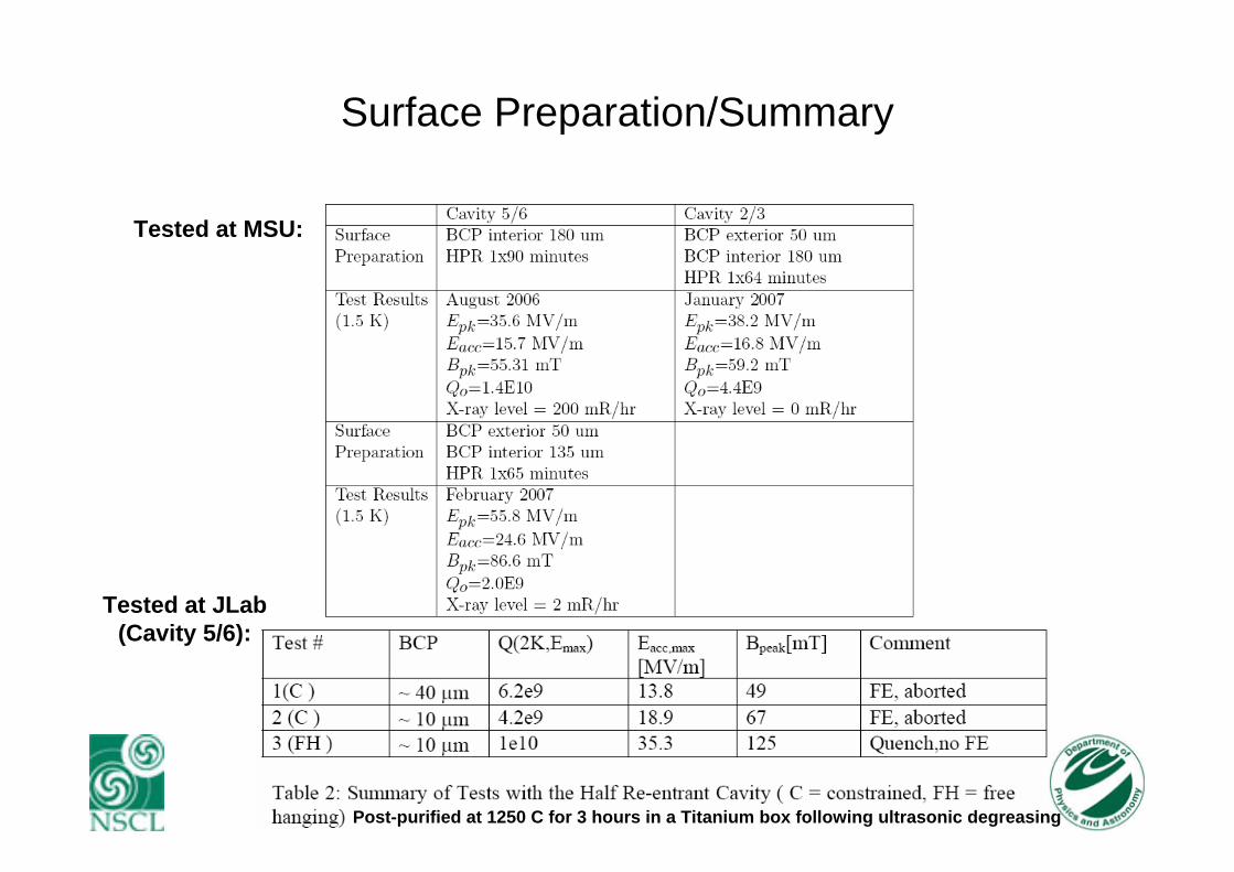
Surface Preparation/Summary
Tested at MSU:
Tested at JLab(Cavity 5/6):
Post-purified at 1250 C for 3 hours in a Titanium box following ultrasonic degreasing
16
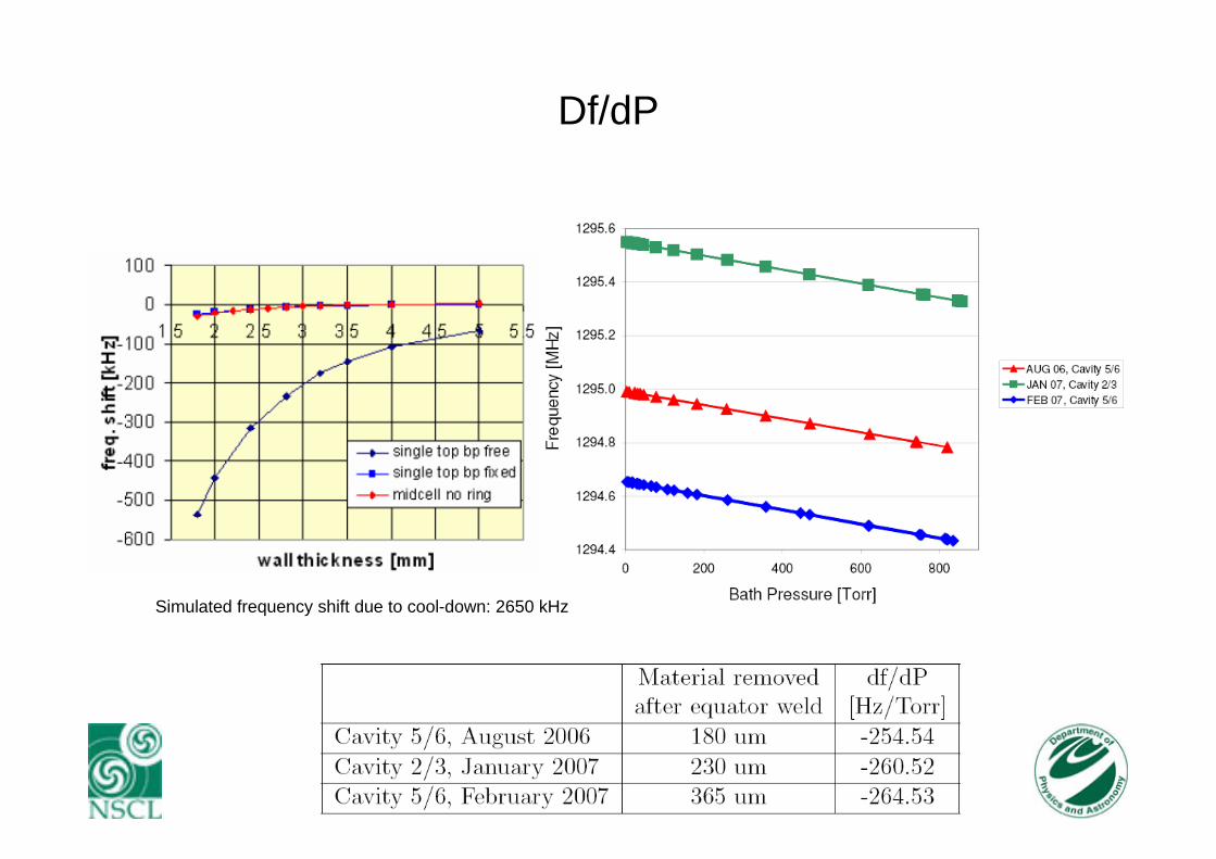
Df/dP
Simulated frequency shift due to cool-down: 2650 kHz
17
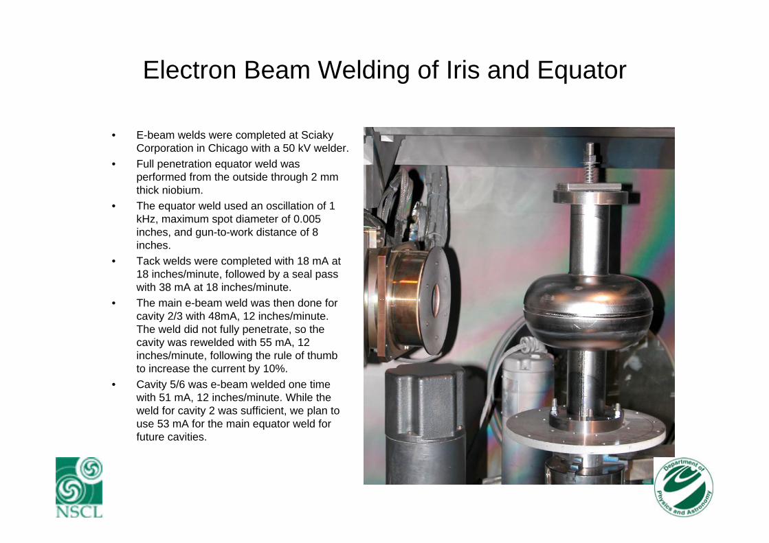
Electron Beam Welding of Iris and Equator
• E-beam welds were completed at SciakyCorporation in Chicago with a 50 kV welder.
• Full penetration equator weld was performed from the outside through 2 mm thick niobium.
• The equator weld used an oscillation of 1 kHz, maximum spot diameter of 0.005 inches, and gun-to-work distance of 8 inches.
• Tack welds were completed with 18 mA at 18 inches/minute, followed by a seal pass with 38 mA at 18 inches/minute.
• The main e-beam weld was then done for cavity 2/3 with 48mA, 12 inches/minute. The weld did not fully penetrate, so the cavity was rewelded with 55 mA, 12 inches/minute, following the rule of thumb to increase the current by 10%.
• Cavity 5/6 was e-beam welded one time with 51 mA, 12 inches/minute. While the weld for cavity 2 was sufficient, we plan to use 53 mA for the main equator weld for future cavities.
18
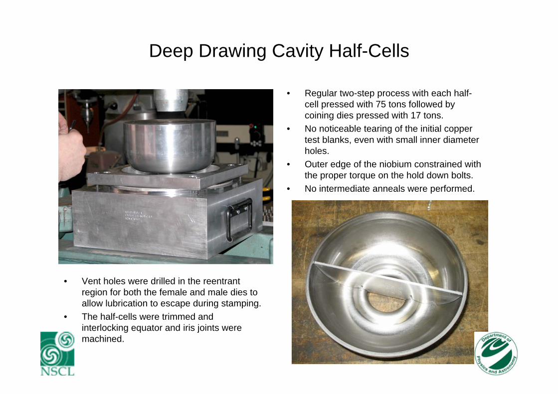
Deep Drawing Cavity Half-Cells
• Regular two-step process with each half-cell pressed with 75 tons followed by coining dies pressed with 17 tons.
• No noticeable tearing of the initial copper test blanks, even with small inner diameter holes.
• Outer edge of the niobium constrained with the proper torque on the hold down bolts.
• No intermediate anneals were performed.
• Vent holes were drilled in the reentrant region for both the female and male dies to allow lubrication to escape during stamping.
• The half-cells were trimmed and interlocking equator and iris joints were machined.

19
Multipacting Simulations for Single-Cell GeometryResults
Multipacting simulations predict:•No hard multipacting barriers.•One soft multipacting barrier in the range of 45 MV/m < Epeak < 70MV/m.•First-order two point multipacting.
20Epk/Eacc = 2.27Bpk/Eacc = 3.52 mT/(MV/m)
Eacc,max = 35 MV/mBpk max=125 mT
Eacc,max,theoretical = 50 MV/m
Test Results
21

22
23
24
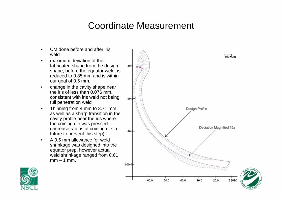
Coordinate Measurement
• CM done before and after iris weld
• maximum deviation of the fabricated shape from the design shape, before the equator weld, is reduced to 0.35 mm and is within our goal of 0.5 mm.
• change in the cavity shape near the iris of less than 0.076 mm, consistent with iris weld not being full penetration weld
• Thinning from 4 mm to 3.71 mm as well as a sharp transition in the cavity profile near the iris where the coining die was pressed (increase radius of coining die in future to prevent this step)
• A 0.5 mm allowance for weld shrinkage was designed into the equator prep, however actual weld shrinkage ranged from 0.61 mm – 1 mm.