ham cram amateur radio technician license review course best when immediately followed by the exam...
TRANSCRIPT

HAM CRAMAMATEUR RADIO TECHNICIAN
LICENSE REVIEW COURSE
BEST WHEN IMMEDIATELY FOLLOWED BY THE EXAM
Revised for post 1 July 2014 Exams
Version Revision 2014r1.0, June 15, 2014WW.W9PE.US
© COPYRIGHT RF gillette inc. Unchanged Reproduction Approved

intentionally blankintentionally blank

IntroductionIntroductionTo obtain your FCC Technician license you will have to pass a test covering; radio Law, operating procedures and technical knowledge. From experience we have found that most wrong answers during testing are on the law and procedures. We assume that is because most taking a cram course have developed some technical knowledge. You must know Ohm’s law algebra or memorize same from the question pool to pass the test. You must also memorize some other data from the FCC rules. Review any license manual before you come to a cram. One is; “The ARRL Ham Radio License Manual 3rd edition, #0222”, at 1-800-326-3942 or www.arrl.org/shop. The entire question pool is in most license manuals and on the web. You can take practice exams using the Internet; www.qrz.com. Your library and community college have public access web terminals. We will cover all of the question’s material in this class.

Electric Units & Ohms LawElectric Units & Ohms Law Voltage (volt) is electromotive force. Current (amp) is electron flow. Resistance (ohm) is the inhibitor to current. Ohm’s law: E (volts) = I (amps) x R (ohms).E = I x R E / I = R E / R = I
Power (watts)=Voltage x Current = E I = W Energy = Power x Time = Watt Hour If required some examples can be added.
By instructor on blackboard. By student to verify understanding.

Conductors Insulators CurrentsConductors Insulators Currents Gold, silver, copper, aluminum and most metals are conductors. Glass, air, plastic, porcelain, mica, oil, dry wood, and dry paper are insulators.
A resistor is a poor conductor and a poor insulator. Direct Current (DC) is unidirectional.
Current from a12 volt auto battery. Alternating Current (AC) continuously changes flow from one direction to the other.
From an 110 volt wall outlet. From a radio transmitter.

FrequencyFrequency Frequency is the number of AC cycles/second.
Hertz (Hz) is the unit for cycles per second. 60 Hz is 60 cycles per second.
Audio Frequencies (AF) = 20 Hz to 20,000 Hz. Communications voice is 300 to 3,000 Hz. (~ 3 KHz.)
Radio frequencies (RF) over 20,000 Hz. High Frequency (HF) 3 to 30 MHz. Very High Frequency (VHF) 30 to 300 MHz. Ultra High Frequency (UHF) 300 to 3000 MHz.
Electromagnetic (Radio) waves consist of: Alternating electric fields & Alternating magnetic fields.
Electromagnetic waves travel @ speed of light. Distance a radio wave travels in 1 cycle is its wavelength.

Frequency and WavelengthFrequency and WavelengthHigher frequencies have shorter wavelength. For
Example: 1KHz shorter wavelength than 500 Hz.

Electrical unitsElectrical units Volts (E); electromotive force. Amps (I); current, electron flow. Ohms (R); resistance to current flow. Henry (L); inductance, passes DC, opposes AC.
Energy stored in a electromagnetic field. The higher the frequency the higher the reactance.
In series reduces AC current while passing DC. In shunt shorts out DC and Low frequencies.
Farad (C); capacitance, blocks DC passes AC. Energy stored in electrostatic field. The higher the frequency the lower the reactance.
In series passes AC while blocking DC. In shunt shorts out AC, tries to hold DC constant.

Electrical AnalogiesElectrical Analogies Volts; water pressure. (AC or DC) Current; water flow. (AC or DC) Ohms; restriction in pipe. (AC or DC) Henry; pinwheel (turbine) in pipe + flywheel.
Passes DC but impedes AC. The larger the inductance the higher the reactance. The higher the frequency the higher the reactance.
Farad; diaphragm across pipe. Stops DC but passes AC. The larger the capacitance the lower the reactance. The higher the frequency the lower the reactance.

Basic ComponentsBasic Components Resistor fixed or variable.
Poor conductor and poor insulator. Specify value-ohms.
Tolerance - %. Size-watts.
How made; Carbon in epoxy. Very thin poor conducting wire. Thin film on insulator.
Potentiometer has 3rd variable terminal. Often used as a volume control.
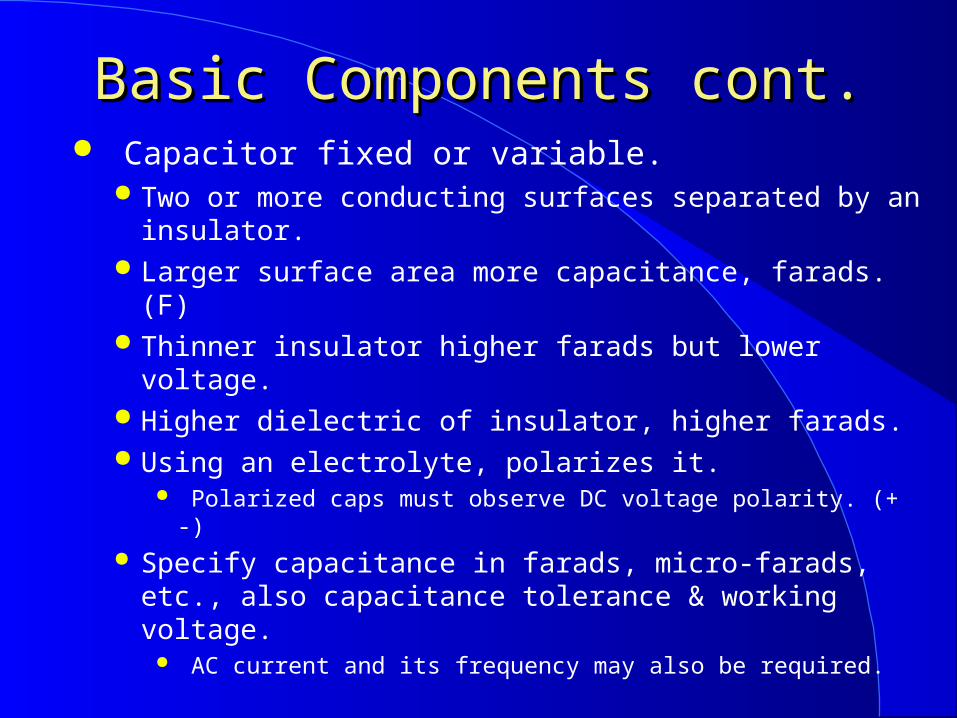
Basic Components cont.Basic Components cont. Capacitor fixed or variable.
Two or more conducting surfaces separated by an insulator.
Larger surface area more capacitance, farads. (F) Thinner insulator higher farads but lower voltage. Higher dielectric of insulator, higher farads. Using an electrolyte, polarizes it.
Polarized caps must observe DC voltage polarity. (+ -) Specify capacitance in farads, micro-farads, etc., also
capacitance tolerance & working voltage. AC current and its frequency may also be required.

Basic Components endBasic Components end Inductor fixed or variable.
Coil of conducting material (wire). More turns more Inductance Henry. (H) Core can add or subtract inductance. Core can also cause inductance to change with
current. Specify inductance in henrys, micro-henrys etc.,
inductance tolerance & current AC & DC. DC resistance may also be a requirement.
Transformers have coupled inductors. Convert AC from one voltage to another. Increase volts than current decreases. The E, I product (watts) is not changed.

Component SymbolsComponent Symbols
R es is tor P otentiom eterC has s is G round
C a pa c ito r a d d + if po la riz e d
+
V a ria b le C a pa c ito r
A nte nn a
A ir C o re Induc tor
V a ria b le Ind uc to r
C ore d Induc to r
T ra n sfo rm e rFuze
AC wall o ut le t
B a tte ry
L am p

Active Component FunctionsActive Component Functions Diodes let current flow in one direction.
Used to rectify, convert AC to DC. Current flows from anode to cathode. But the electron charge flows the other way!
Zener diodes have a constant voltage for a range of reverse currents. They are voltage regulators over that range.
Light emitting diodes convert current into light. Bipolar and field effect transistors amplify
(provide gain) and on-off switching. Integrated Circuits combine multiple functions
into one package.

Active Component Symbols Active Component Symbols
Intergrated Circuit IC
Z e n e r D io de
A no de C a th o de
L ig ht E m itting D io de
Diode
Anode CathodeMarked w ith
Stripe
S witc h, s ingle po le single throw. W hen activated by cored inductor a R e lay.
G a te
S o u rc e
Dra in
F ie ld E ff e c t T ra n sisto r
NPN Bipolor Transistor
B a s e
C o lle c to r
E m itter
Not-Pointing-in

Symbols interconnected to make Symbols interconnected to make an Amplifier Schematic an Amplifier Schematic
What do the numbered symbols depict?

Power Supply SchematicPower Supply Schematic
What do the numbered symbols depict?

Antenna Tuner Schematic Antenna Tuner Schematic (Matching Network)(Matching Network)
What do the numbered symbols depict?

DC MeasurementsDC Measurements Current meters are amp meters, milliamp meters or micro amp meters.
A current meter (amp/microamp meter) is used in series with the current (in parallel it may be a short and burn out the meter.)
A volt meter (current meter with resistor in series) is used across (in parallel) the circuit.
Increase resistance for higher voltage reading. An ohm meter is a known voltage source in series with current meter.
The current that flows is inversely proportional to the resistance completing the circuit.
A multi meter reads E, I, or R and is also called a VOM (VVolt OOhm MMilliamp meter.)

Circuit MeasurementCircuit Measurement Volt meter used across the circuit, in parallel. Current meter (amp meter) is used in series. Power (watts) = Voltage x Current = E I
What happens if the amp meter is across the source? What happens if the voltmeter tries to measure amps?
IEAMP METERVOLT METERRLOADSOURCE
IEAMP METERVOLT METERRLOADSOURCE
Source
Am ps
V oltm eterm icroam pm e ter with 1 m ohm series resistor
Am pm eter
Load Resis tor
V olts
E = IR = 1 m icroam p*1 m egohm = 1v i.e . the volt m eter reads 1 v / m icroam p.

Circuit Measurement cont.Circuit Measurement cont. Ohm meter is a known voltage source
and current meter.– Current inversely proportional to resistance.
What happens when it is connected to the resistor, capacitor and 100v source?
Ohm s
Resistor Capaticor
+10 v
O hm m e te ra m p m e ter w ith kn o wn vo lta ge so u rce .
100 v
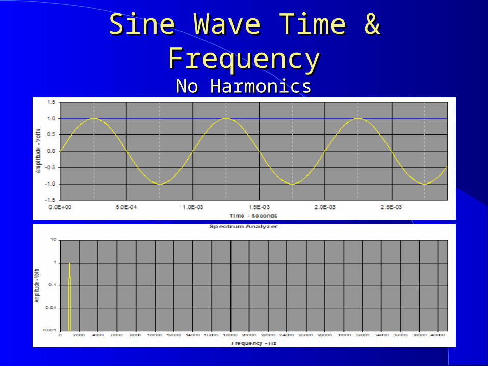
Sine Wave Time & FrequencySine Wave Time & FrequencyNo HarmonicsNo Harmonics

Clipped Sine Wave & SpectrumClipped Sine Wave & SpectrumClipping generates odd harmonics.Clipping generates odd harmonics.
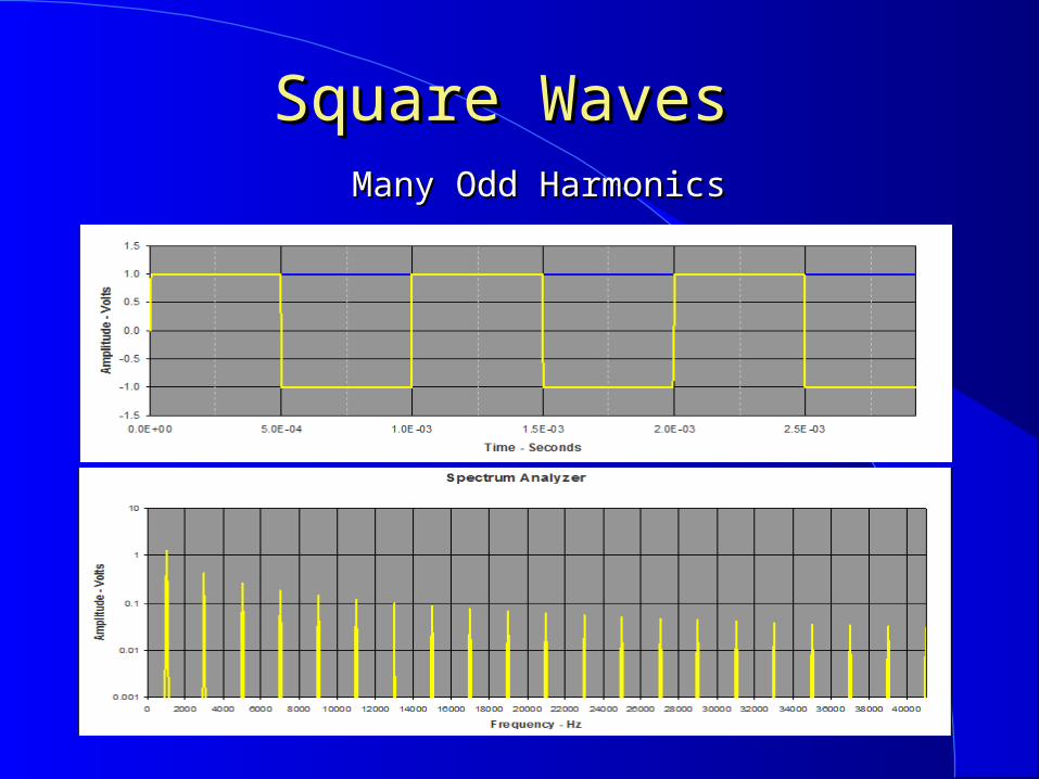
Square Waves Square Waves Many Odd HarmonicsMany Odd Harmonics

Radio Frequency Filters Radio Frequency Filters Low Pass or RF Filter to eliminate all RF.
Passes all frequencies below its cut off frequency.
High Pass Passes all frequencies above its cut off frequency.
Band Pass Passes all frequencies near its center frequency.
Band Stop or Notch Filter Passes all frequencies except those near its center
frequency.
Filters are not perfect The better the filter the more and/or sharper its cut off.

InterferenceInterference Electro Magnetic Interference (EMI) is controlled by good design.
No spurs, splatter or unwanted frequencies from transmitter.
If you receive a complaint check your transmitter. Check your TV for the interference.
Unwanted frequencies controlled by filtering and shielding.
Cable TV operates in HAM bands. A loose or broken coax connector (yours or theirs) is
a poor shield. You could interfere with TV or cable TV with you.

TV Radio InterferenceTV Radio Interference Turning up the microphone gain to increase power
could reduce understanding due to distortion. Carrier Harmonics would be generated by any
clipping, or distortion in the transmitter. Splatter is generated by modulation clipping.
Spurious emissions are signals other than desired. Harmonic radiation, splatter and spurious emissions
are always the Ham’s problem.
Optional 100% AM no clipping Carrier and modulation clipped
lab1 15000 1000 1 1 1 0 FFT lab2 15000 1000 1 1.1 1.1 0 FFT

Filter ApplicationsFilter Applications
A low pass filter at the output of a transmitter will eliminate transmitter harmonics.
A 15M technician transmitter (21.1 to 21.2 MHz) with a low pass filter at 22 MHz will suppress harmonics at 2F (21x2 = 42 MHz) 3F (21x3 = 63 MHz (channel 3)) etc.
A high pass filter at the TV input will prevent front end overload from a close 15 meter transmitter.
Adding a band pass filter at the TX output will also eliminate TX spurious emissions.
Adding a notch filter (band reject) at the TV could eliminate 2 meter (144 - 148 MHz) RF overload.

More on InterferenceMore on Interference
Receiver overload: Interference caused by a strong close signal is receive frequency independent.
Check and tighten coax at transmitter and receiver. If transmitter is OK (your radio &TV is interference
free) it is the receiver owners problem. Filtering/shielding of receiver is required, but: The FCC can set your frequencies and hours if the
receiver is of good engineering design. Telephones can act as HAM radio receivers.
Many cordless phones have poor RF front end designs. A wired phone can be fitted with a RF / low pass filter. A ferrite choke around the phone cord is an RF / low pass
filter.

EMIEMI A neighbor’s unlicensed equipment may also
cause you interference. Many appliances generate RF. They all require FCC part 15 Approval.
If one causes you interference: Make sure it is an interference problem, not a station
problem. Try to ID the interfering item / equipment.
Ask your neighbor what they are using at the time of interference, or what is on all the time.
Politely inform them of the problem and the FCC rules. They have to stop use if it interferes with a licensed service HAMs are a licensed amateur radio service.

Scientific NotationScientific Notation
1,000,000,000 (9 zeros) = 1 X 10⁹ GIGA 1,000,0001,000,000 (6 zeros)(6 zeros) = = 1 X 101 X 106 6 MEGAMEGA
1,0001,000 == 1 X 101 X 103 3 KILOKILO 11 == 1 X 101 X 100 0 UNITUNIT .01 (2 right of .) = 1 X 10⁻² CENTI
.001 .001 (3 right of .) = = 1 X 101 X 10-3 -3 MILLIMILLI .000001 = 1 X 10⁻⁶ MICRO .00000001 = 1 X 10⁻⁹ NANO .000000000001 = 1 X 10-12 PICO
Example: Speed of light = 300 x 106 meters per second. Note: Bold may be on license exam.

Frequency to WavelengthFrequency to Wavelength Frequency MHz = 300300 / free space wavelength. (meters)
= 985 / free space wavelength. (feet)– 300300 / 80 meters = 3.75 MHz = 985 / 249.6 feet.
Free space wavelength (meters) = 300300 / frequency. (MHz)– Free space wavelength (feet) = 985 / frequency. (MHz)– 300 / 150 MHz = 2 meters, 985 / 150 = 6.57 feet.
The wavelength in a wire is about 0.95 of free space. Antenna wavelength (feet) = 985 * 0.95 / frequency. (MHz)
= 936936 / frequency. (MHz)
– ½ wavelength () antenna (feet) = 468 / frequency. (MHz)
– ¼ wavelength () antenna (feet) = 234 / frequency. (MHz)
• 12 times feet equals inches. (234 x 12 = 2808.)
– ¼ wavelength () antenna (inch) = 2808 / frequency. (MHz) Important, add some chalk talk examples or do some yourself.

Simple AntennasSimple Antennas A dipole is a half wavelength (½ ) antenna.
An easy to make / erect wire HF antenna.
A dipole antenna has a doughnut pattern. Visualize the dipole passing through the doughnut hole. Maximum radiation is at right angles to antenna length. A ¼ vertical with its ground plane has the same pattern, but only
one half of the doughnut. The other half is “underground”. An easy to make VHF/UHF antenna. A rubber ducky is a poor ¼ antenna with a poor ground plane. A poor antenna is poorer in a car or metal enclosure. Vertical is non directional, good for mobile & roof good ground plain.
RF radiation has electric & magnetic fields & polarization. Elements parallel to the ground – horizontal electric field, h-pol. Elements perpendicular to the ground – vertical electric field, v-pol. Cross polarized antennas reduce line of sight signals 100’s of
times.
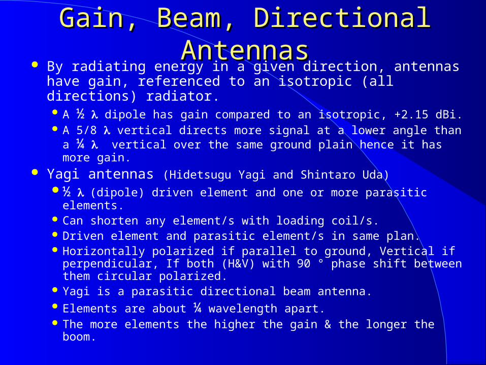
Gain, Beam, Directional AntennasGain, Beam, Directional Antennas By radiating energy in a given direction, antennas have
gain, referenced to an isotropic (all directions) radiator. A ½ dipole has gain compared to an isotropic, +2.15 dBi. A 5/8 vertical directs more signal at a lower angle than a ¼
vertical over the same ground plain hence it has more gain. Yagi antennas (Hidetsugu Yagi and Shintaro Uda)
½ (dipole) driven element and one or more parasitic elements. Can shorten any element/s with loading coil/s. Driven element and parasitic element/s in same plan. Horizontally polarized if parallel to ground, Vertical if
perpendicular, If both (H&V) with 90 ° phase shift between them circular polarized.
Yagi is a parasitic directional beam antenna. Elements are about ¼ wavelength apart. The more elements the higher the gain & the longer the boom.
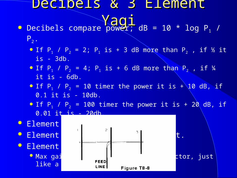
Decibels & 3 Element YagiDecibels & 3 Element Yagi Decibels compare power; dB = 10 * log P1 / P2.
If P1 / P2 = 2; P1 is + 3 dB more than P2 , if ½ it is - 3db.
If P1 / P2 = 4; P1 is + 6 dB more than P2 , if ¼ it is - 6db.
If P1 / P2 = 10 timer the power it is + 10 dB, if 0.1 it is - 10db.
If P1 / P2 = 100 timer the power it is + 20 dB, if 0.01 it is - 20db.
Element # 1 is the reflector. Element # 2 is the driven element. Element # 3 is the director.
Max gain (7+ dBi) is away from reflector, just like a flashlight.

Other Gain Antennas Other Gain Antennas Cubical quad.
Full wave, square driven and parasitic elements. ¼ on each side, 1 total length. Fed from bottom, horizontal polarized from side vertical.
Parabolic Antennas. Parabolic reflectors reflect received signals to the focus. Driven element at focus reflects most signals straight out.
Directional antennas are useful for radio direction finding (RDF) and hidden TX / interference finding.
Antennas can have loss. A small rubber ducky may have -10 dBi gain.
-10 dB is a power reduction of 1/10th or 0.1.• In a steel car it may have 20 dB loss• - 20 dB is a power reduction of 1/100th or 0.01.

Antennas / Dummy LoadsAntennas / Dummy Loads Multi band antennas save transmission line and
switches, but will transmit harmonics. A dummy load is a non-radiating transmitter load.
A dummy load is matched to the transmitter, usually 50 ohms.
Non-inductive resistor that does not change value when used within its rating.
Minimum load power rating must equal transmitter power output.
Used for testing or tune-up to avoid transmitter radiating. ID when testing if you are not sure that you are not radiating.
An antenna analyzer can detect resonant frequency. It also provides information on the match/VSWR.

Transmission LinesTransmission Lines Transmission line / feed line connect the radio to a remote
antenna. Losses increase with frequency. Losses increase with mismatch (high standing wave ratio.) Losses heat transmission line.
Unbalanced, non-symmetrical about the feed point. One conductor and return: coax, micro strip etc. Coaxial cable is preferred at the transmitter.
Balanced, symmetrical with respect to ground. 300 ohm TV twin lead almost no longer used. 600 ohm common for balanced antennas. Twin lead is affected by close metallic objects. It can not be buried.
A BALUN, BALBALanced to UNUNbalanced is used between a balanced system (twin lead) & unbalanced (coax.)

Coaxial CableCoaxial Cable Good quality well constructed coaxial cable will
minimize RF leakage and loss. Coaxial cable has a center conductor surrounded by an
insulator which is covered by a conducting shield. Coaxial cable is weather proof if solid outer cover. Coaxial cable has an impedance in the range of most amateur
antennas with 50 ohms being the most common.• TV coax is 75 ohm, other impedances exist.
• Coaxial cables can be buried.• Coaxial cable is not affected by close metallic objects.
Moisture penetration is the common failure mode. Sunshine weakens the outer covering or it corrodes.
• Rain water then enters.• Water has bigger effect on air/foam dielectric than on solid.

Transmission Line LossTransmission Line Loss All transmission lines have loss.
Twin lead has less loss than coax. Open air dielectric twin lead lowest loss. Larger diameter coax lower loss than smaller.
Air dielectric lowest loss, solid dielectric highest loss. Losses increase with frequency.
Coaxial connectors also have loss. “VHF” (“PL-259”) OK for HF and VHF. At UHF and higher frequencies “N” or an other low
loss type should be used. Maximum power is delivered with matched
radio, transmission line & antenna impedance.
VSWR / SWRVSWR / SWR Voltage Standing Wave Ratio (VSWR / SWR).
A measure of how well the load is matched to the TX. Ratio of maximum to minimum voltage on a
transmission line or a feed line.
A SWR of 1:1 indicates a perfect match of the transmitter impedance to its antenna system, > 1:1 = Z mismatch.
High VSWRs (> 3:1) are usually not acceptable as transmitter can be damaged and power loss is very high. Solid state TX start to cut back power output at ~ 2:1 VSWR.
If the VSWR was once ok, a high VSWR indicates a bad antenna, transmission line and/or loose connection.
Antenna tuner matches impedance between transmitter and antenna system. Allows antenna to work on multiple frequencies.

VSWR MeasurementVSWR Measurement A standing wave ratio (SWR) meter is connected
where you want to check the match. Usually between transmitter and the feed line. At the antenna if you are only checking the antenna. Long feed lines lower the reading.
An RF watt meter is connected at the transmitter output to measure transmitter power output. RF watt meters are usually 50 ohms.
A directional watt meter measures forward (TX to Ant.) and reflected power (Ant. to TX.) True forward power = forward power reading less reflected
power reading. This is another way to measure VSWR. VSWR = (1+√(Reflected/Forward) / (1- √(Reflected/Forward))

ModulationModulation Modulation is varying some characteristic of an
emission for the purpose of conveying information. A constant amplitude radio signal is an RF carrier.
FM and AM transmitters without modulation produce a carrier wave.
A carrier without side bands is usually a test signal. It also could be a bad modulator or a bad audio section.
An interrupted (on-off) carrier is a CW or pulse emission. The on-off is amplitude modulation.
AM conveys information by varying the amplitude of the carrier, producing sidebands.

AM SpectrumAM Spectrum

More on ModulationMore on Modulation Amplitude modulation has a carrier and lower and upper side
bands. CW is AM on-off modulation. AM modulation uses audio to change the RF amplitude. A detector demodulates and recovers the audio.
If one sideband and the carrier are eliminated it results in single side band suppressed carrier (SSB) modulation.
A product detector recovers CW and SSB modulation. Requires 2 inputs, signal and Beat Frequency Oscillator (BFO).
Over modulating of an AM or SSB transmitter causes clipping, harmonics and out-of-channel emission (splatter).• Reduce audio gain/talk softer.
Optional DSBSC, filter one SB = SSBSC BFO product detecting a 30000 Hz carrier for a 800 HZ audio output
lab3 30000 2000 0 1 1 0 FFT lab4 30000 30800 0 1 1 0 FFT

FM/PM SpectrumFM/PM Spectrum

Modulation EndModulation End For FM the carrier is moved to convey information.
FM carrier movement/deviation is proportional to the amplitude of the modulation, the rate of movement conveys the info. Freq.
Phase modulation causes frequency modulation and visa-versa. A reactance modulator produces phase modulation. Larger deviation results in wider bandwidth. A frequency discriminator demodulates FM after limiting amplitude. Over modulating of an FM transmitter causes out-of-channel
emission (splatter.)• Reduce the audio gain, or talk softer.
A keyed audio tone used as the input to an FM, AM or SSB transmitter is modulated CW (MCW.)
PSK-31, RTTY and Packet radio uses Frequency Shift Keying. With FSK, the carrier moves between two frequencies.

BandwidthBandwidth Modulation has side bands and requires bandwidth.
CW uses the narrowest bandwidth (<150 KHz.). Then RTTY/ PSK-31. SSB voice (2 to 3 kHz). AM (twice the bandwidth of SSB). FM communication voice (10 to 15 kHz).. High data rate digital (higher data rate = higher bandwidth). Fast scan TV (NTSC) (6 MHz).
Digital modes like packet use more bandwidth as their speed increases.
The narrower the bandwidth, the higher the signal to noise ratio for a given TX power. A signal is readable at a longer distance. CW / low data rate digital best for longest range like EME.

RADIO BASICSRADIO BASICS A radio receiver converts radio frequencies into
usable frequencies, audio for a phone receiver. A detector is required (product-CW SSB, discriminator
FM). Speaker, headphone/s or earphone/s are also required.
An Oscillator, RF source is required for a TX. A straight key, electronic keyer, CPU with keyboard
etc. in used to transmit international Morse code. A radio phone modulator converts/imparts voice
information into radio signals. A microphone is required.
When a radio TRANSmitterr is combined with a radio reCEIVER it is called a TRANSCEIVER.
Amplifiers. Preamplifier increase receiver sensitivity/low level signals. Power amplifier to increase TX power.

Modern Transceiver UseModern Transceiver Use Most parameters can be stored in memory.
TX and RX frequency, CTCSS tone frequency, TX power level, etc. This allows fast access to a favorite frequency/mode.
Use the tuning or VFO knob or keypad to select frequency. Use squelch control to eliminate noise when no RX signal. Use noise blanker to reduce ignition interference. AGC automatic gain control keeps received audio even. Microphones may have PTT and up/down buttons for
frequency or memory selection, connector has PS voltage. The shift control changes the RX/TX frequency offset. Change RX frequency via receiver incremental tuning RIT.
Will also change CW/SSB pitch as will changing the BFO freq. The step function modifies the frequency tuning rate. The “F” key allows keys to perform an alternate function.

Battery BasicsBattery Basics There are many types of Batteries.
Lead-acid - rechargeable 12v. auto battery. Carbon Zinc - short life non rechargeable 1.5v AA, etc. Alkaline - long life non rechargeable 1.5v AA, AAA etc. Nickel-cadmium - rechargeable 1.2v AA, AAA etc. Nickel Metal Hydride, better - rechargeable 1.2v AA etc. Lithium-ion - rechargeable & non rechargeable 3.2v.
• Longest life (most amp hours / cubic inch). Rechargeable Batteries require maintenance:
Recharge every 6 months. Store cool and dry, same temperature across entire
battery as voltage changes with tenperature. No physical damage.
Batteries supply maximum energy (watt hours) with a slow discharge (low current).

Battery ConsiderationsBattery Considerations Every battery can explode or heat to a dangerous
temperature if charged or discharged at to fast a rate. Follow the manufactures instructions, a short is dangerous.
Lead acid auto type batteries can be charged by an auto or truck in an emergency. Connect in parallel with existing battery and run engine. They have additional hazards.
When charging they give off hydrogen gas. If not properly vented this can be an explosion hazard.
They contain sulfuric acid at concentrations high enough to burn people.
Just a little in the eye can cause blindness. The acid can destroy clothing, rugs etc. The acid can stain / etch many materials.
Be extra careful when moving, charging or using them.

MiscellaneousMiscellaneous Solder Connections.
Flux allows solder to flow on oxidized surfaces. Two types of flux:
Rosin; OK for electrical circuits. Acid; current will corrode & fail connection.
Never use acid flux on electrical circuits. A bright shinny joint is a good solder connection. A gray dull joint is a cold joint/bad solder connection
A power supply converts AC, for example; from a wall outlet to DC. It can make low-voltage, high-voltage or both. DC to DC power supplies also exist.

MiscellaneousMiscellaneous Peak envelope power (RF output) is measured at the
antenna terminals of the transmitter. Peak Envelope Power (PEP) is the average power
during one RF cycle at the crest of modulation. Peak reading watt meter used for voice PEP. For mobile operation a filter cap will reduce alternator
wine (Variable high pitch wine on transmitted and/or received signal) and RF pickup on power leads.
A regulated power supply prevents voltage fluctuations.
Chirp, a shift in operating frequency verses time, (during a transmission) is eliminated by regulating the transmitter oscillator's power supply voltage output.

Problem SolvingProblem Solving If a HAM (new or otherwise) has a problem it will be
solved quicker by offering to help then complaining. If a microphone is close to its speaker it may allow
feedback (oscillate / squeal.) If someone reports that your signal through a repeater
is garbled and weak, you may be off frequency. If someone reports that your SSB signal is grabbled
and breaking up, you may have spurious emissions caused by RF getting into the TX via the microphone.
A headset with microphone would help when operating in a noisy place.
If you disconnect the TX power / batteries and / or microphone it can help to avoid unauthorized use.

PropagationPropagation
Radio signals propagate out to the radio horizon, just like light, if they are not refracted (bent) or reflected. Radio horizon is a little further than earth’s curvature blockage.
Sky wave propagation involves radio signals that are reflected back to earth by the ionosphere. This provides extended radio range, i.e. the signal "skips" back
to earth, the level is variable and polarization is lost. The ionosphere is the part of the upper atmosphere
where ions and free electrons effect radio waves. The sun's ultraviolet radiation ionizes the outer atmosphere, as
does solar flux from a flare. The more sunspots the greater the ionization. Ionization is minimum just before sunrise.
Sunspots, solar flares radiation levels have an 11 year cycle.

More Propagation More Propagation The maximum usable frequency (MUF) is the
highest frequency usable between two points. The higher the solar radiation the higher the MUF
and the more absorption of the low frequencies. The next layer, the E layer (60-70 miles) is the
lowest region useful for long distance (DX) radio. Sporadic E most likely in summer daylight on the
VHF bands. The F2 layer (F1 140 miles - F2 200 miles) is most
responsible for HF (3 to 30 MHz) long distance radio.
At night F1 and F2 combine.

More PropagationMore Propagation
Signals that take off near vertical and are higher in frequency than the critical frequency pass through the ionosphere. VHF/UHF signals usually pass through the ionosphere.
Ground wave propagation involves radio signals that travel along the surface of the earth. The earth seems less curved to radio waves than to light.
VHF / UHF communication at close range is line of sight, by direct wave, and preferred when useable as no interference is caused to distance stations.
For very high solar radiation (high sunspots) six or ten meters best for long distance communications.

Propagation EndPropagation End Large metallic objects and metal frame buildings
can act as mirrors and reflect VHF/UHF and other signals. Multipath may add to or cancel radio signals.
Antenna movement can mitigate this cancellation. The Troposphere is below the ionosphere and is
where temperature changes with altitude. VHF/UHF signals can bend around the earth’s curvature
often 300 miles or more if there is a troposphere temperature inversion.
Knife edge refraction can bend VHF/UHF signals over mountain ridges.
Meteors have ionized tails and VHF/UHF signals can reflect / scatter for distant communications. Six 6 meters is best band for meteor scatter.

LunchLunch
If you had a problem with any material, see us during lunch we can help.
We will restart exactly one hour from now. If you have extra time check if there are any exam
instructions and/or forms to fill out during lunch.

5 Principles / Purposes5 Principles / PurposesOf Amateur RadioOf Amateur Radio
► Providing emergency communications.
► Advancement of the radio art.
► Improvement of communication and technical skills.
► Increasing the number of trained operators and electronic experts.
► Enhancement of international good will.
Amateur means nonprofessional, i.e. no money made
or expense paid/reimbursed, “no pecuniary interest.”

Federal Communication Federal Communication Commission (FCC)Commission (FCC)
The FCC makes the rules, and regulates Amateur Radio Service in the US, its territories and on its vessels, only the FCC.
Amateur Rules are Part 97 of Title 47 CFR (Code of Federal Regulations.)
General provisions, Operating standards, Special operations, Technical standards, Providing emergency communications, Qualifying examination systems.
Appendix 1 - Places where amateur service is regulated.Appendix 2 - VEC regions and volunteer examiners.
No construction standards, but:Good Engineering Practices.Good Amateur Practices

FCC LicenseFCC License The Amateur Radio license is both a station and
operator authorization granted by the FCC. A station is the apparatus necessary for radio com. An amateur radio operator is one holding a FCC
license to be a control operator. Must be: in the FCC database or an alien with reciprocal
operating authorization. Good only where the FCC regulates or where there are
reciprocal operating agreements .
Anyone, any age (except a representative of a foreign government) can become a HAM.

LicenseLicense The FCC may revoke or supped your license if they
do not have your current mailing address. Requires you to receive U.S. mail from the FCC
The license is for 10 years, with a 2 year grace period for renewal, no grace period for operating.
You can operate when and only when your license is in FCC data base.
1-888-CAL-LFCC http://wireless.fcc.gov/uls/
Only one primary station license per person. After upgrading from Technician to General before
the upgrade is in the FCC database you can use your call with /AG.

Control OperatorControl Operator The control operator is the licensed amateur that is
responsible for a radio stations transmissions. Required whenever the station is transmitting locally or by
remote control. Not required when under approved automatic control.
The control point is where the station control functions and operator are located.
The station licensee and the control operator is responsible for the stations transmissions.
Must follow the FCC rules and If reciprocal operating must follow the foreign country rules. In Canada call/VE# & once during the communication, you
must state your geographical location, like "30 km north of Toronto.“
European & all other CEPT reciprocal licenses.• Check for exact information before operating.

Control OperatorControl Operator
If you (the station licensee) give another licensee permission to be the control operator, the FCC holds both of you responsible for proper operation. If your call is used you are assumed to be the control
operator, so document who is the control operator.
An amateur licensee cannot be a control operator for a higher class of station when it is operating beyond the control operator's license, but any station can be operated to the license privileges of the control operator. If higher privileges are being used that call must be used
followed by your call.

More InformationMore Information The FCC can inspect your station and its records at
any time. A volunteer examiner (VE) is a HAM accredited by
one or more VECs who volunteer to administrate the license exam.
Three examiners are required to give an exam. To administer the Technician exam they (VEs) must
hold a General (or higher) class license. The International Telecommunication Union (ITU)
coordinates Frequency allocations to reduce interference and optimize spectrum use.
The U.S. is in ITU region 2, Guam is in region 3. Ham assigned frequencies/bands vary by ITU.

Amateur License ClassesAmateur License Classes In order of increasing control operator privileges.
Technician• Test element 2, 35 multiple choice questions.
• General• Extra
The amateur radio license authorizes the equal use of specific operating frequencies, modes and transmitter power. The higher the license class the higher the privileges. But no higher priority for any given frequency.
The Amateur radio frequencies / bands are often referred to by their approximate wavelength.

Technician VHF/UHF FrequenciesTechnician VHF/UHF Frequencies 6 meters - 50 to 54 MHz 2 meters - 144 to 148 MHz 1.25 meters - 222 to 225 MHz
219 to 220 MHz secondary use only for point to point digital message forwarding.
70 centimeters* - 420 to 450 MHz no 420 to 430 MHz north of line A (south of Canada.)
33 centimeters* - 902 to 928 MHz 23 centimeters* - 1240 to 1300 MHz Other higher frequencies* Band edge operation is risky without very expensive
test equipment. * Hams may be a secondary user: Cannot interfere with primary even if the
primary is outside of the US & may have geographic/power limits.

Technician PrivilegesTechnician Privileges Technicians have all Amateur privileges and operating
modes above 50 MHz + some below. Amateur radio transmitter power output is limited to
the smallest amount that is required for communications, and not to exceed 1500 watts PEP.
Beacons are for observation of propagation and are limited to 100W PEP. They are one way and automatic control may be allowed.
Some sub bands have mode limitations. 6 meters, 50.0 to 50.1 MHz - CW only. 2 meters, 144.0 to 144.1 MHz - CW only. 1.25 meters, 219 to 220 MHz - Point/Point CW & Data only.

Technician HF PrivilegesTechnician HF Privileges 3675 to 3725 kHz - 80 meter band - CW only. 7025 to 7125 kHz - 40 meter band - CW only. 21,100 to 21,200 kHz - 15 meter band - CW only. 28,100 to 28,300 kHz - 10 meter band - CW,
RTTY and Data only. 28,300 to 28,500 kHz - 10 meter band - SSB
including SSB MCW only. Band edge operation is risky as it is easy to
transmit out of band. (drift, sidebands etc.) Power output on the above frequencies is limited to
200 watts PEP. HAMs have no distance limit when they transmit.

U.S. Call SignsU.S. Call Signs ITU Prefix (before number) 1, 2, or 3 letters. First letter K, N, W or Letter A _ (but only AA to AL). Number 0 to 9 Issued by FCC radio district.
Map on next slide. Call not changed if you move out of district.
Suffix (after number) one, two, or three letters. Sequentially assigned in strict alphabetical order.
Technician or General call signs: Group C 1x3 calls with N, K, W.
Group C is used up and now is only by vanity request. Group D 2x3 beginning with K or W i.e. K_#_ _ _.
They do not include Group B _#_ _ or _ _ #_ . Special event call signs, 1x1, No X & 15 days max.
–

US Call District MapUS Call District Map
More on U.S. Call Signs More on U.S. Call Signs Tactical call signs are efficient and help coordinate
public service communication. Examples: command post, weather center, races HQ.
Under the vanity call sign program you can request any nonissued call sign from groups allowed for your license class. But not: _H, _L or _P unless you live there I.e. _H is Hawaii +,
_L is Alaska and _P is Puerto Rico +. You can change your call (non vanity / no choice) by
requesting a systematic call on form 605. Any HAM can apply for a temporary 1x1. Club call signs are via a club call sign administrator.
– A club must have at least 4 members.– Vanity club Call Sign selected only by license trustee.

Station IdentificationStation Identification You must call sign identify your station every 10
minutes (or less) and at the end of every contact. You do not have to ID for the first 10 minutes.
ID test transmissions use the same rules. Testing without ID is an illegal unidentified transmission.
If using a special event call for ID, your call 1/ hour. If you add some self-assigned indicator it must not
conflict with an FCC rule indicator or an ITU prefix. ID can always be in CW or in the operating mode.
CW ID 20 wpm maximum, a reason to know CW. ID must be in English, phonetics OK, ITU best.
All understand A)lfa B)ravo …not A)rdvark B)ackstroke. Space stations, higher then 50 Km do not require ID.

CommunicationsCommunications Third party communications are passed by amateur
radio for someone other than the two operators in contact, or directly to/by a third party. Foreign third party traffic is prohibited without an treaty or
agreement, except when the third party is licensed.
If third party traffic is exchanged with a foreign station, the foreign station must also be identified by you at the end of contact.
You can communicate with all amateur stations, on frequencies authorized by your license, unless prohibited by our or their government. The FCC can OK communication with other radio services,
for example US military com. test on Arm Forces Day.
Re-TX of auxiliary, repeater or space station OK.

ProhibitionsProhibitions Broadcasting, transmitting information, music or video
to the general public is prohibited. No news reporting. Beacons, remote control, Ham information bulletins,
emergency com & code practice are not broadcasting. International, HAM related or personal remarks only. No business communications except when safety of
life, immediate protection of property is threatened. No call to your boss to request customer directions. Occasional sale or trade of HAM equipment OK.
No compensation of any type is permitted for HAM communication services, some part 97 exemptions.
Club employee sending bulletins and/or CW practice. But not for any other control operator actions.
Teachers incidentals to instruction.

More ProhibitionsMore Prohibitions Regular communication that can reasonably furnished
by an other radio service is not permitted. Music transmission by phone is prohibited.
Authorized re-broadcasting of space shuttle com/music OK.
No obscene, indecent or profane words or language. It is offensive to some. Children may be listening. No list exists.
The use of cipher to obfuscate is prohibited, published ciphers meeting special requirements may be OK.
Radio control, and space station control ciphers OK.
No false or deceptive signals or communications. No HAM interference to Radio Navigation Services.
Prohibitions EndProhibitions End An amateur may never transmit without identification.
No repeater testing without ID. No unidentified communications or signals.
Model radio control is limited to 1W. No ID required if name, address & call are on the transmitter. It is not considered cipher.
No HAM space stations on 6 m or 1.25 m. You must NEVER willfully, maliciously or harmfully
interfere with a radio communication or signal. Listen before you start to transmit. If you accidentally interfere. ID and change frequency.
If amateur station shares frequency, or is a secondary band user it must not cause harmful interference. Listen before you use a new Frequency.

EmergenciesEmergencies Mayday for phone and SOS for CW are emergency
signals only for immediate danger to life or property. They are always assumed to be real. You are required to give them immediate priority. False use of them is a crime that can lead to: jail and / or
a fine and / or loss of license. Health and welfare messages are relief traffic, but they are
not emergency traffic.
If you receive an emergency distress signal from a station outside your operator privileges you can assist using any radio communications at your disposal.
If you are in a situation without normal communications and immediate safety of human life or property is threatened you may use any radio communications at your disposal. (No non HAM frequencies when phone working.)

Emergency PreparednessEmergency Preparedness You must prepare before an emergency, as it is to
late during one. Check twice a year that your emergency equipment is
in working condition and where it belongs. This applies to home and work even without HAM radio. Also know what is not needed, for example a 1500 w. amp.
Have emergency power available. Portable generator. Charged batteries. Portable solar panel
Participate in emergency nets and drills. Learn how to run a net. Learn how to handle HAM radio traffic.
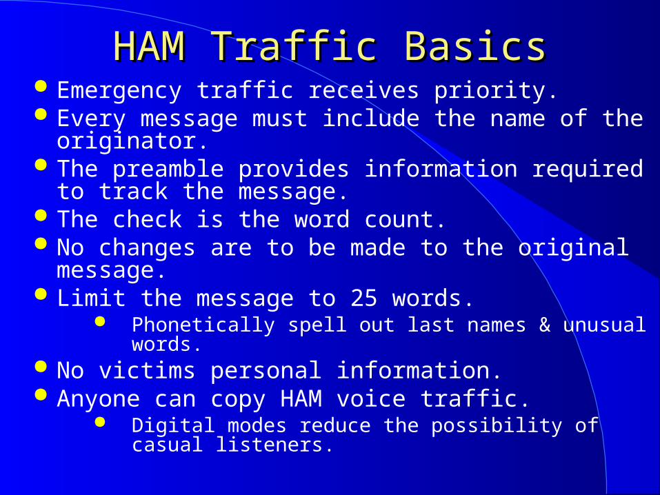
HAM Traffic BasicsHAM Traffic Basics Emergency traffic receives priority. Every message must include the name of the
originator. The preamble provides information required to track
the message. The check is the word count. No changes are to be made to the original message. Limit the message to 25 words.
Phonetically spell out last names & unusual words. No victims personal information. Anyone can copy HAM voice traffic.
Digital modes reduce the possibility of casual listeners.

Communication EmergencyCommunication Emergency The FCC engineer in charge of an area is authorized
to declare a temporary state of communications emergency when a disaster disrupts normal communications. Then only essential communication and relief use of amateur radio is allowed in accord with specific conditions and rules that are spelled out.
*****************************VOLUNTARY COMMUNICATIONS EMERGENCY - DECLARED
DUE TO THE EXPECTED IMPACT OF HURRICANE ON THE TEXAS COAST, ALL AMATEURS ARE REQUESTED TO COOPERATE BY RECOGNIZING THE EXISTENCE OF A VOLUNTARY COMMUNICATIONS EMERGENCY AND THEREFORE RELINQUISHING THE USE OF FREQUENCIES 7285 kHz (EMERGENCIES) AND 7290 kHz (HEALTH AND WELFARE) DURING THE DAY AND 3873 kHz (EMERGENCIES) AND 3935 kHz (HEALTH AND WELFARE) DURING THE EVENING HOURS. THE FREQUENCIES ARE TO BE CLEARED WITHIN 3 kHz EITHER SIDE OF EACH FREQUENCY.
THE COMMUNICATIONS EMERGENCY REMAINS IN EFFECT UNTIL RESCINDED.
SIGNED: OLIVER LONG FCC HOUSTON RESIDENT AGENT
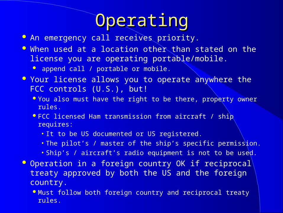
OperatingOperating An emergency call receives priority. When used at a location other than stated on the
license you are operating portable/mobile. append call / portable or mobile.
Your license allows you to operate anywhere the FCC controls (U.S.), but! You also must have the right to be there, property owner rules. FCC licensed Ham transmission from aircraft / ship requires:
• It to be US documented or US registered.• The pilot’s / master of the ship’s specific permission.• Ship’s / aircraft’s radio equipment is not to be used.
Operation in a foreign country OK if reciprocal treaty approved by both the US and the foreign country. Must follow both foreign country and reciprocal treaty rules.

Contact ProceduresContact Procedures CQ and your call sign is a general call to invite any
HAM station to make contact with your station. In CW do not send it faster than you can receive.
To initiate a contact call CQ (3 x 3 recommended) except on a repeater. CQ CQ CQ this is W9PE W9PE W9PE CQ CQ CQ DE W9PE W9PE W9PE K, in CW.
Answer 1 x 1 (phonetically OK) voice: N9EW this is Whiskey 9 Papa Echo, answer 2 x 2 CW.
On a repeater to establish contact; General CQ W9PE or just W9PE When in use W9PE (during a break) Specific (them first) N9EW this is W9PE (you last)
Your call between transmissions is a way to join a conversation on any frequency.
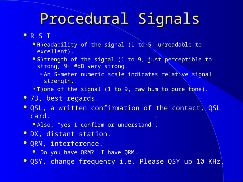
Procedural SignalsProcedural Signals R S T
R)eadability of the signal (1 to 5, unreadable to excellent). S)trength of the signal (1 to 9, just perceptible to strong, 9+
#dB very strong.• An S-meter numeric scale indicates relative signal strength.
• T)one of the signal (1 to 9, raw hum to pure tone).
73, best regards. QSL, a written confirmation of the contact, QSL card.
Also, “yes I confirm or understand”.
DX, distant station. QRM, interference.
Do you have QRM? I have QRM.
QSY, change frequency i.e. Please QSY up 10 KHz.

QSL CardQSL Card

EmissionsEmissions An RF signal is an electromagnetic emission. CW (continuous wave) uses international Morse code
on-off keying of a transmitter. (≈150 Hz bandwidth) CW can be CPU generated & decoded.
AM, amplitude modulation. (≈ 6 KHz BW (bandwidth)) SSB, single sideband suppressed carrier.
It is a form of AM. (≈ 2 to 3 KHz BW) Upper side band above 40 meters, (2 meters is
above 40 meters) & LSB on 40 m and down.
FM, Frequency Modulation. (NBFM ≈ 5 - 15 kHz BW) Fast scan TV (≈ 6 MHz BW) Slow scan is FM or SSB. CW, SSB and low data rate (low bandwidth) digital,
like PSK-31 are weak signal modes. Lower BW = lower noise, better signal/noise
(S/N).

More on EmissionsMore on Emissions AM, SSB & FM voice are “Phone” transmissions. MCW uses an on-off tone as input to a phone TX. Once FM signals are above threshold they have a good S/N
(full quieting) and good audio fidelity. Full Quieting when signal overcomes all receiver noise. Less effected by static & interference than AM modes (SSB). Set squelch to the point that just silences background noise. A stronger FM signal can capture (suppress) a weak one.
Continuous Tone-Coded Squelch System (CTCSS) or PL is a sub-audible tone used to open a tone squelched receiver.
Newer squelch is Digital Code Squelch (DCS). Carrier squelch (detects signal level) is also used. European repeaters use a tone burst for access. Simplex operation; TX & RX on the same frequency.
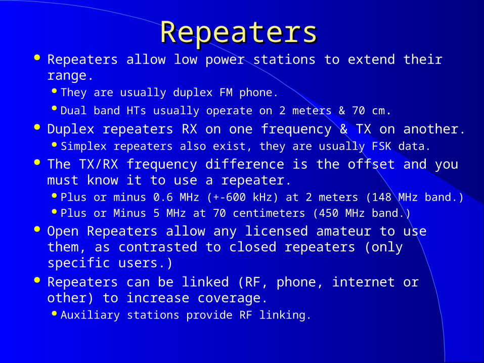
RepeatersRepeaters Repeaters allow low power stations to extend their range.
They are usually duplex FM phone. Dual band HTs usually operate on 2 meters & 70 cm.
Duplex repeaters RX on one frequency & TX on another. Simplex repeaters also exist, they are usually FSK data.
The TX/RX frequency difference is the offset and you must know it to use a repeater. Plus or minus 0.6 MHz (+-600 kHz) at 2 meters (148 MHz band.) Plus or Minus 5 MHz at 70 centimeters (450 MHz band.)
Open Repeaters allow any licensed amateur to use them, as contrasted to closed repeaters (only specific users.)
Repeaters can be linked (RF, phone, internet or other) to increase coverage. Auxiliary stations provide RF linking.

More on RepeatersMore on Repeaters Pause between repeater TX to allow others to use.
Keep transmissions short, wait for a courtesy tone before TX. A beep when repeater TX ends & its receiver is open.
Monitor before using. To check if in range, ID with call sign, do not kurchunk.
Use simplex when possible to keep repeaters open. Check the repeater input to see if simplex is possible.
The originator is responsible for illegal retransmissions. Both originator and repeater licensee are if they are ongoing.
Repeaters have automatic time out circuits to limit the length of a signal transmission.
Repeaters usually ID in MCW. Repeater owners pay all costs, users donate.
Autopatchs & Band PlansAutopatchs & Band Plans An autopatch is a device that allows users to make public
telephone calls from HTs or mobile stations. An autopatch is not private, the public can listen.
Band plans (beyond FCC) are voluntary guidelines for using different modes on various frequencies. They reduce interference and conserve spectrum. Developed by HAMs for HAMs.
For example;146.52 MHz is the national simplex FM calling frequency.
Recognized frequency coordination body approved repeaters have priority over uncoordinated ones. Frequency coordination body; HAMs selected by HAMs.
Otherwise stations including uncoordinated repeaters have equal rights to a frequency, and the equal responsibility to avoid EMI. Repeaters are treated the same as any other mode. If you interfere you
should ID and move to a different frequency.

Data ModesData Modes FCC calls telemetry (measurement), telecommand
(control) or CPU (communication) emissions Data. Digital modes use FM at UHF/VHF, SSB at HF. RTTY Radio TeleTYpe uses narrow band frequency
shift keying (FSK) and is direct (machine/cpu) printing.Uses a modem, and a teleprinter or computer system.RTTY RX and TX must be at the same speed (baud.)
PSK-31 is a form of digital modulation that uses a computer sound card and frequency shift keying (SK).
31 Hz bandwidth allows good signal to noise ratios.• Small bandwidth requires a low data rate.
• Great for low power long distance communications.• It uses BPSK (binary phase) modulation without error correction
or QPSK (quadrature) modulation with error correction (-3dB.) Digital modes with error correction help with QRM.
A parity bit flags bad data and retransmission is requested.

Packet & Digital RadioPacket & Digital Radio Packet Radio uses a (terminal node controller) TNC
between the computer/dumb terminal and the radio. No Microphone is required, modulation is supplied by the TNC. Each data packet has a header; Who to, who from, check sum,
auto repeat request if the check sum is in error, etc. Being connected in packet mode means you are sending only
to the connected station, and it is acknowledging correct receipt. Monitoring is receiving all messages, but no acknowledgment.
Digipeaters retransmit data that is so marked. A packet node network, interconnects stations to
transfer data over long distances including satellites. Computer sound cards provide many digital modes.
Received signals are converted to digital data for CPU use. Data to be transmitted is converted to audio for TX mike input.

Other ModesOther Modes Digital transmissions should be avoided on band plan
designated simplex frequencies. The higher the data rate, the wider the bandwidth.
19.6 Kilo baud max. on 6 and 2 meters. Modern digital data TX provides high speed reliable
communications with low bit error rate (BER). Multipath may increase BER, but ARQ can detect errors &
request retransmission. NTSC TV: cable channel 57 to 60 is a fast scan
HAM band TV receiver. (Bandwidth = 6 MHz) National Television System Committee, USA analog TV.
Telecommand is one way TX to initiate, modify, or terminate functions at a distance. Wire or radio used for connection. License copy must be posted. Must be protected from unauthorized transmission.

Internet and HAM RadioInternet and HAM Radio A gateway connects a HAM station to the internet. Two common interfaces are Echolink and IRLP.
Both use voice over internet protocol (VoIP.) Both have online directories.
Echolink using a CPU + sound card provides both: A HAM to HAM Voice over Internet Protocol (VoIP) link. A HAM to remote Transceiver link, TX use is license class
limited. You can call CQ on many foreign repeaters. Foreign DX stations can call CQ on many US repeaters or radios.
IRLP is the Internet Radio Linking Project for VoIP. DTMF, telephone touch tones for command data via VoIP. Active nodes are found in the repeater directory or on the
Web. You use DTMF tones to select a specific IRLP node.
You can use IRLP from a HT if an active node is in range.

Location InformationLocation Information Radio direction finding (RDF) is used to locate RF
transmissions and or noise. The fox hunting slide that follows has more RDF information.
APRS is Automatic Packet Reporting System. Supports quick real-time exchange of information.
Position shows on map, includes moving position via GPS Status and messages including inquiries.
Each station with new information transmits his new data to everyone in the net and every station captures that information for consistency to all participants.
Internet linking can be included. Automatic control is used for network digipeters.
Latitude and longitude define exact position. Grid squares define close position.
A picture is worth 1000 of words. http://www.levinecentral.com/ham/grid_square.php


HAM SatellitesHAM Satellites HAM satellites are repeaters, they use different input
(uplink) and output (downlink) frequencies. World wide communication is possible when both stations have
a clear path to the satellite. By using the minimum needed transmitter power you prevent
the satellite’s radio receiver from overloading.
To use a satellite your license class must allow operation on its uplink frequency.
Satellites move, antenna pointing may be required. LEOs Low Earth Orbit satellites move fast, pointing is required. The longest path to a satellite that is on the horizon.
It is also the one that changes least with time. Easiest for antenna pointing.
Satellite rotation may cause spin fading.
More on HAM SatellitesMore on HAM Satellites Due to motion their frequencies have Doppler shift.
Keplerian elements define the orbit. Satellite tracking software allow 3 dimensional (azimuth &
elevation) antenna pointing and Doppler shift correction. Satellite beacons contain information about them. The International Space Station’s HAM operations are
on VHF (2 meters) & UHF (70 cm.) frequencies. Any Technician licensed HAM can contact it. International space station contact good for about 4 to 6 min.
The building and launch of most amateur radio satellites is coordinated by AMSAT. The Radio Amateur Satellite Corporation.
The HAM band plan has satellite sub-bands.– 435 to 438 MHz is the 70 centimeter satellite sub-band.

Fox Hunting & ContestingFox Hunting & Contesting Fox hunting; using RDF to locate a TX
A direction vector to the signal is recorded. Repeat from other location/s Multiple vectors intersect at the source.
Highest amplitude; gain antenna rotated to direction. Amplitude comparison; Equal signal amplitude from 2 antennas
with over lapping patterns rotated together. Phase comparison; 2 antennas equidistant to source have the
same phase, source broadside to them.
Contesting Work as many other HAM stations as possible during
the contest time period following contest rules. Winning operators have developed great operating skills
(minimizing the time to convey the requited information), have picked the right tine for each band, have optimizes their station and may even have had a little luck.

RACES & ARESRACES & ARES Radio Amateur Civil Emergency Service.
Supports local state and federal governments. You must register with the local civil defense origination to
participate. Amateur Radio Emergency Service.
Supports agencies I.e. red cross, weather service etc. Any HAM can volunteer, register equipment & participate.
Both provide communications during emergencies. Emergency nets.
Net control should be a station that has a strong clear signal. After check in, TX only when asked or if an emergency. In an emergency and no net, do not wait, start it yourself.
Take check-ins pass off control when required. Avoid casual chatter when ever you are involved in a
public service net, it may interfere with important info.

VHF / UHF OperatingVHF / UHF Operating The higher the frequency easier to propagate through
small openings. UHF is better at penetrate buildings, than VHF. But the higher the frequency the greater the path loss.
Repeaters are vertically polarized. HT held with its antenna vertical has lowest path loss.
If your direct line of sight to a repeater is blocked moving or rotating the antenna may open a reflective path and/or provide multipath enforcement.
If operation while moving multipath can cause the signals to have AM, picket fence modulation. Named picket fence as it can sound like a stick clicking a fence
as someone walks along it, faster travel faster clicks. Aurora reflection is also a moving multipath generator.
Signals very and sound different (garbled).

Electrical SafetyElectrical Safety 1/10 amp (100 ma) of current may be fatal to the heart.
Disrupts body electrical functions. Involuntary Contractions and Heating.
Voltages over 30 volts can be dangerous. Use safety interlock switches with higher voltages. High voltage capacitors can hold lethal charges.
All should know location & use of main power switch. Ground all your equipment for safety and minimum EMI.
The 110V green wire is used only for chassis ground. The white wire and silver screw are common not ground.
Ground Fault Interrupters (GFIs) add additional safety. Fuse or circuit breaker required for all equipment.
Interrupts power if overload, prevent fire but only if correct size. Fuse both lines for mobile radios at battery/source.

Lightning SafetyLightning Safety Ground all radio and connected equipment.
Minimum 8 foot ground rod at each tower leg bounded to legs and each other with short wide connections.
Follow local building codes. Use lightning protectors on all antenna & rotor lines. Controlling lightning current flow prevents electric shock & fires.
Large currents result in large voltages with even with R~0. 10,000 Amps / 0.01 ohms = 100 volts To avoid large voltage differences between equipments
bonding must be very low resistance & Inductance. Wide conductors have low inductance.
Extra precautions during a storm. Disconnect antennas & separate from equipment. Unplug power cables from equipment. Stay out of radio room.
Antenna SafetyAntenna Safety Do not put towers and antennas or feed lines near or
where they can contact High Voltage lines. 10 foot minimum safety margin if one falls.
There are tower height restrictions near airports. Keep antennas away from places where they can be
contacted during transmission. Even low power can cause an RF burn.
The metal roof of automobile is the safest antenna mobile mounting spot as it is hardest to reach and the roof provides good shielding to the occupants.
Do not work on a tower or antenna if storm possible. Make sure tower & guy wires are in good condition.

More Antenna Safety More Antenna Safety Never climb a crank-up tower unless it is full down.
It is a guillotine if a cable breaks. Do not work alone & wear safety harness.
Tower and guy wires in good condition before climbing. Follow manufacture’s instructions. Stainless steal hardware minimizes corrosion. When working under the person on the tower wear a
safety hat and safety glasses. Bring all tools needed to minimize trips up tower. Use a gin pole when lifting so not to lift above tower.
Temporary pole above tower with pulley and cable on top. When using a Bow and Arrow or a Sling Shot practice
People, Property, Power line (PPP) safety.

Radiation IdentificationRadiation Identification

RF SafetyRF Safety Amateur Radio Transmitters do not emit any ionizing
radiation. Amateur Radio Transmitters do emit RF heating
radiation, like microwave ovens. Heating is dependent upon the material, the RF
frequency and the RF power level.
The FCC requires all radio transmitters to meet RF radiation exposure limits to assure a safe operating environment for amateurs, their family and neighbors.
The FCC radiation Maximum Permissible Exposure (MPE) limits are defined in the FCC rules part 1 and in the FCC office of Engineering and Technology (OTE) bulletin 65.

RF Safety Understanding.RF Safety Understanding. All amateurs are responsible for not exceeding the
MPE limits. You also must indicate that you have read and
understand these rules on the amateur license application form at the time of application.
The limits are in milliwatts per square centimeter as a function of frequency.
The following FCC graph will aid in understanding the limits.
We will also provide an easy way to be safe and to comply with the FCC requirements.

RF Safety Exposure LimitsRF Safety Exposure Limits

More RF Safety More RF Safety The MPE is not uniform across the RF spectrum because
the body absorbs some frequencies better than others. 30 to 300 MHz are the frequencies that are easiest for the body to
absorb and convert to heat. MPE levels are also different for controlled (your property) and
uncontrolled environments (where anybody can be). Eyes are the most sensitive, as heating can cause
cataracts. HTs (used within 20 cm from body) all have limits on RF
power to meet RF safety. For extra safety keep the antenna of a HT away from your eyes.
Never look into an open wave guide when RF is applied. Never operate a power amplifier with its shields / covers
removed.

RF Safety ComplianceRF Safety Compliance If you your antenna (including repeater antennas) is
collocated with other antennas the total radiation from all transmitters must be considered.
You do not have to make measurements or perform complex calculations or use computer models to verify that you meet the requirements.
But you can use them as a way to comply. Simple tables are available in the FCC office of
Engineering and Technology (OTE) bulletin 65, and from other sources including the ARRL.
The FCC has provided an even easier way to verify that you meet the requirement, as no evaluation is required if you have PEP into the antenna below 50 watts.

MPE Evaluation Limits MPE Evaluation Limits

Easy MPE EvaluationEasy MPE Evaluation Operating FM at 50 watts or less would in itself be
sufficient to meet the safe operating environment rules.
Furthermore duty factor reductions are allowed as heating is duty factor dependent.

Easy ComplianceEasy Compliance SSB operation at 100 W. or less would also qualify as a
duty factor of 50 % is given, even with heavy speech compression.
Conversational CW at less than 125 watts (0.4 duty factor * 125 W. = 50 W.) would also qualify.
In addition if you only use the transmitter for 3 minutes out of 6 minutes you can double the above qualifying power levels for a controlled environment (15 out of 30 minuets for an uncontrolled environ.)
Last but not least, note that the power levels given are at the antenna, hence cable losses apply.

More Easy ComplianceMore Easy Compliance Most will meet the requirements by making note of
the power run on each band. The note of your evaluation is kept available at the
station, it is not mailed to the FCC or anybody. IF you are running more power or have antennas
with gain, then use the tables in FCC Office of Engineering and Technology (OTE) bulletin 65. http://www.fcc.gov/oet/info/documents/bulletins/ In most cases these tables will eliminate the need for
calculations or measurements. The tables take into account power, antenna gain (pattern)
distance and frequency. A sample table follows.
Reevaluate if you change equipment.

Table ExertsTable Exerts

Good LuckGood Luck
I hope to talk to you on a HAM band.
W9PE
WWW.W9PE.US

NotesNotes
Options called out refer to the D column settings in
W9PE’s virtual lab. See http://w9pe.us/w9pe0513vl.pdf
US Call District Map by AA7OA
Radiation identification illustration, RF safety tables and
Graphs from the FCC office of Engineering and
Technology (OTE) bulletin 65.