ham radio 2013 - sdr-kits
TRANSCRIPT
ProgramProgram
• Scattering (S-) parameters
Break• Break
• Measuring S-parameters with a VNAMeasuring S parameters with a VNA
• Applicationspp
Many thanks to:- Eric Hecker - Gerfried Palme - Jan Verduyn
Kurt Poulsen Alan Rowe Jim Tonne
HAM RADIO 2013 2
- Kurt Poulsen - Alan Rowe - Jim Tonne
2
What are Scattering Parameters?What are Scattering Parameters?
1. A different angle to dc2. a and b instead of voltage and current2. a and b instead of voltage and current3. Complex reflection coefficient4 S t4. S-parameters
HAM RADIO 2013 33
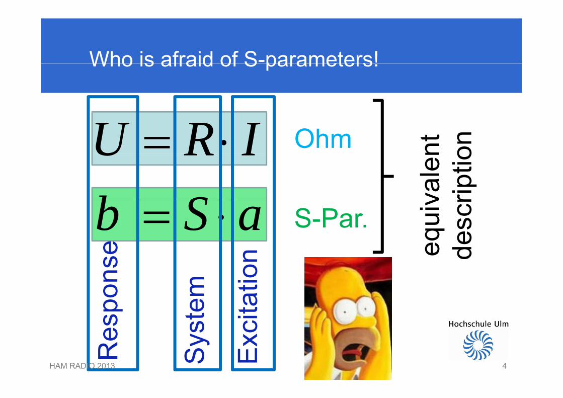
Who is afraid of S-parameters!Who is afraid of S parameters!
U R I Ohm nt onU R Ib S va
len
riptio
b S a S-Par.
e equi
ves
cr
tion
onse
m
e d
xcita
t
espo
yste
m
HAM RADIO 2013 4ExRe
Sy
4
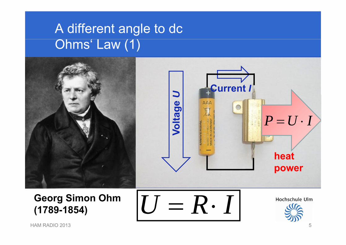
A different angle to dcOhms‘ Law (1)
U Current I
ltage
U
P U I
Vol P U I
heatpower
Georg Simon Ohm U R I HAM RADIO 2013 5
(1789-1854) U R I 5
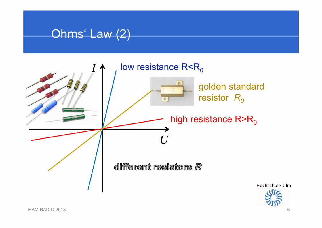
Ohms‘ Law (2)Ohms Law (2)
I low resistance R<R0
golden standardgolden standardresistor R0
U
high resistance R>R0
U
HAM RADIO 2013 66
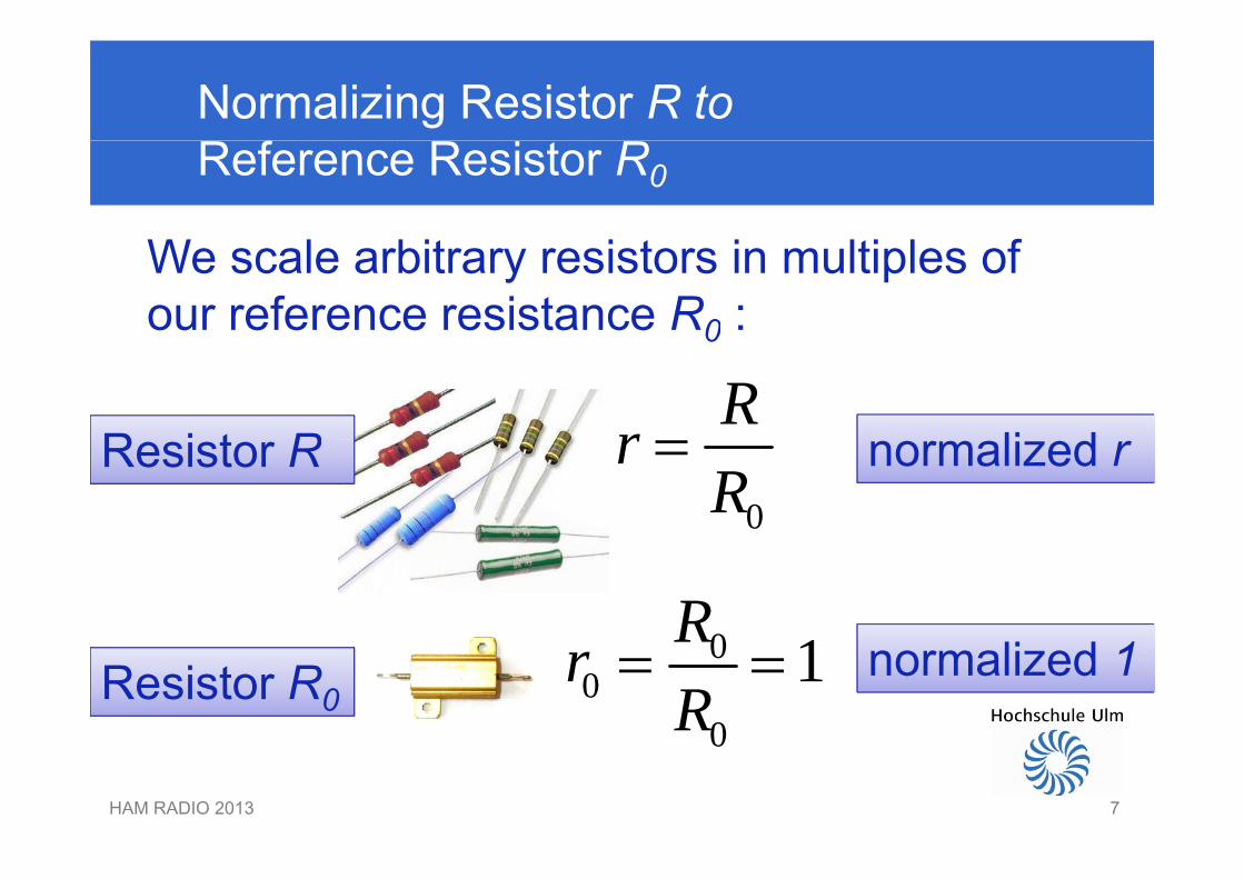
Normalizing Resistor R toReference Resistor R0
W l bit i t i lti l fWe scale arbitrary resistors in multiples ofour reference resistance R0 :0
RrR i t R li d0
rR
Resistor R normalized r
0 1R00
0
1RrR
Resistor R0normalized 1
HAM RADIO 2013 7
0
7
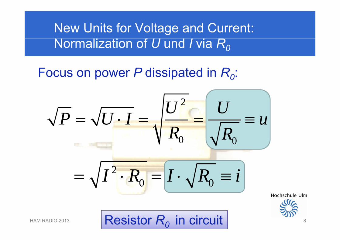
New Units for Voltage and Current:Normalization of U und I via R0
Focus on power P dissipated in R0:
2U UP U I u 0 0
P U I uR R
2I R I R i0 0I R I R i
HAM RADIO 2013 8Resistor R0 in circuit8
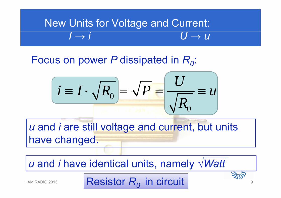
New Units for Voltage and Current: I → i U → u
UFocus on power P dissipated in R0:
0Ui I R P uR
00R
u and i are still voltage and current, but unitshave changed.g
u and i have identical units, namely √WattHAM RADIO 2013 9
u and i have identical units, namely √Watt
Resistor R0 in circuit9
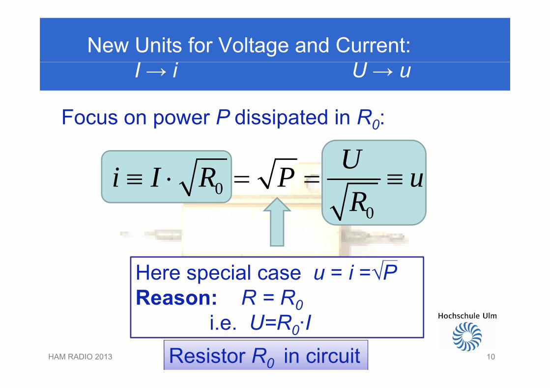
New Units for Voltage and Current: I → i U → u
UFocus on power P dissipated in R0:
0Ui I R P uR
00R
Here special case u = i =√PpReason: R = R0
i e U=R0·IHAM RADIO 2013 10
i.e. U R0 I Resistor R0 in circuit
10
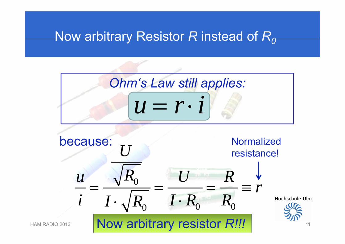
Now arbitrary Resistor R instead of R0Now arbitrary Resistor R instead of R0
Ohm‘s Law still applies:
u r i
Ubecause: Normalizedi t !U
Ru U Rresistance!
0
0 00
Ru U R ri I R RI R
HAM RADIO 2013 11
0 00i I R RI RNow arbitrary resistor R!!!
11
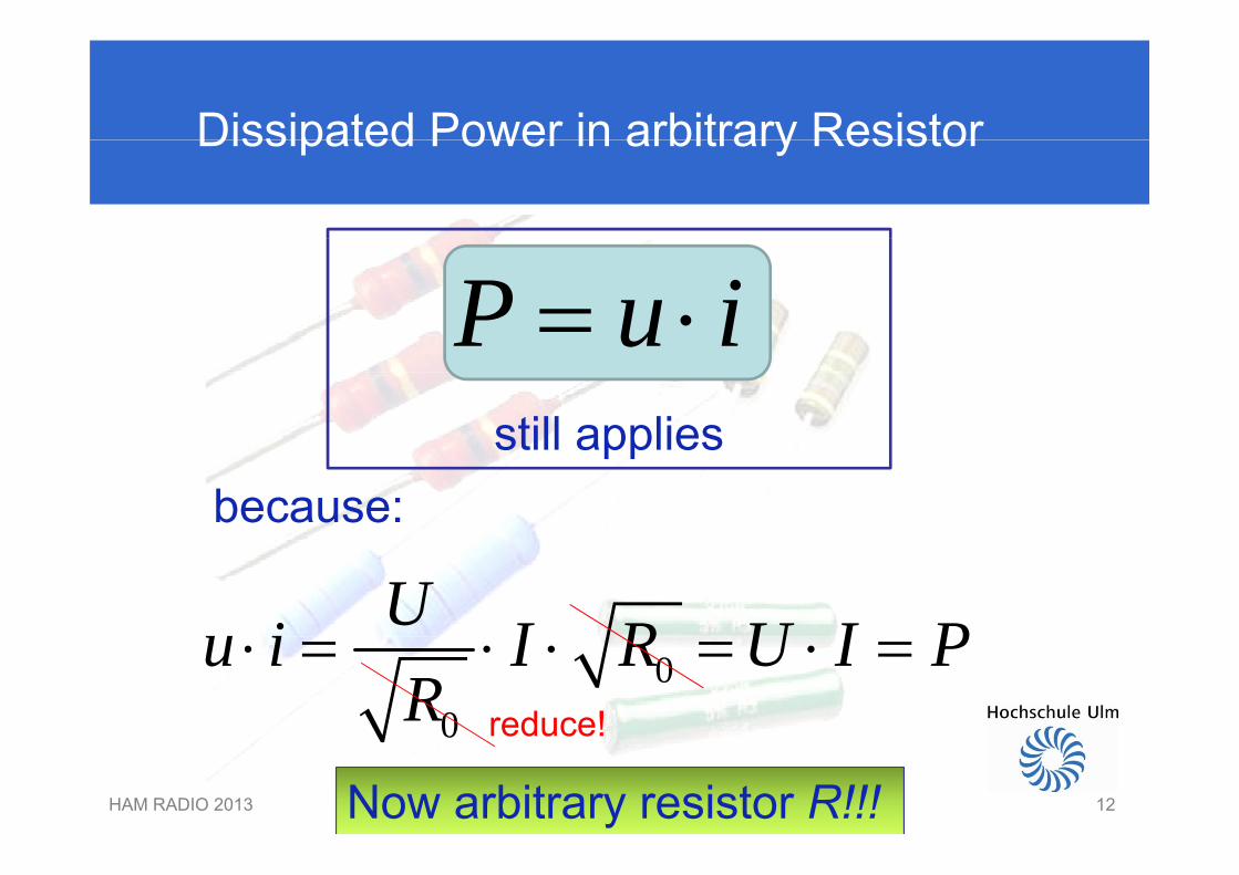
Dissipated Power in arbitrary ResistorDissipated Power in arbitrary Resistor
P u i still applies
P u istill applies
because:
Ui I R U I P00
u i I R U I PR
reduce!
HAM RADIO 2013 12
0 reduce!
Now arbitrary resistor R!!!12
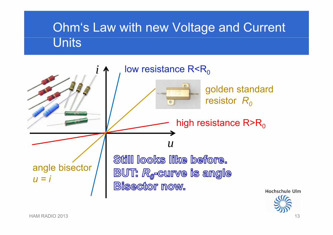
Ohm‘s Law with new Voltage and CurrentUnits
i low resistance R<R0
golden standardgolden standardresistor R0
u
high resistance R>R0
u
angle bisectorgu = i
HAM RADIO 2013 1313
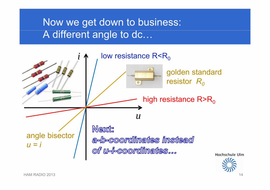
Now we get down to business:A different angle to dc…
i low resistance R<R0
golden standardgolden standardresistor R0
u
high resistance R>R0
u
angle bisectorgu = i
HAM RADIO 2013 1414
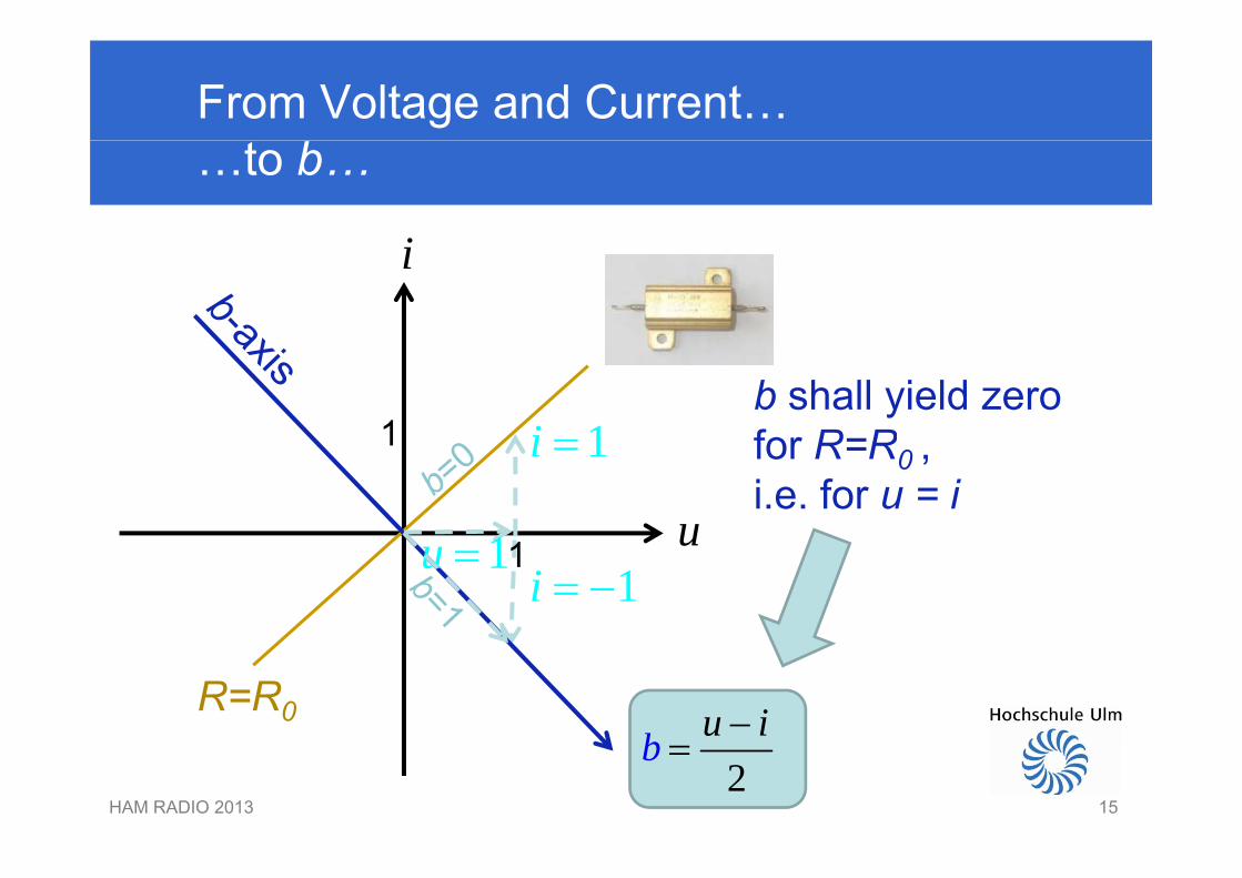
From Voltage and Current……to b…
ii
1b shall yield zerofor R=R1i
u
1 for R=R0 , i.e. for u = i
1
1i
u11u 1i
R=R0b u i
HAM RADIO 2013 152
b
15
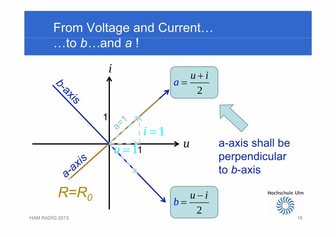
From Voltage and Current……to b…and a !
ii
2a u i
1
2
u
1
11i
a-axis shall beu11u a axis shall beperpendicularto b-axis
b u iR=R0
to b axis
HAM RADIO 2013 162
b 0
16

This works the other way round, too:Voltage and Current from a and b
i a bi a b
a Arbitrary resistor R can beArbitrary resistor R can bedescribed equivalently in (u,i) or (a,b)-coordinates.
u a b
b
R
HAM RADIO 2013 17
b
17
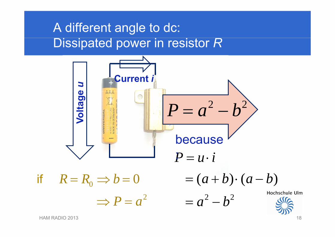
A different angle to dc: Dissipated power in resistor R
e u Current i
Volta
ge 2 2P a b
V
becauseP u i :
2 2
( ) ( )a b a bb
02
0R R b
P
if
HAM RADIO 2013 18
2 2a b 2P a
18
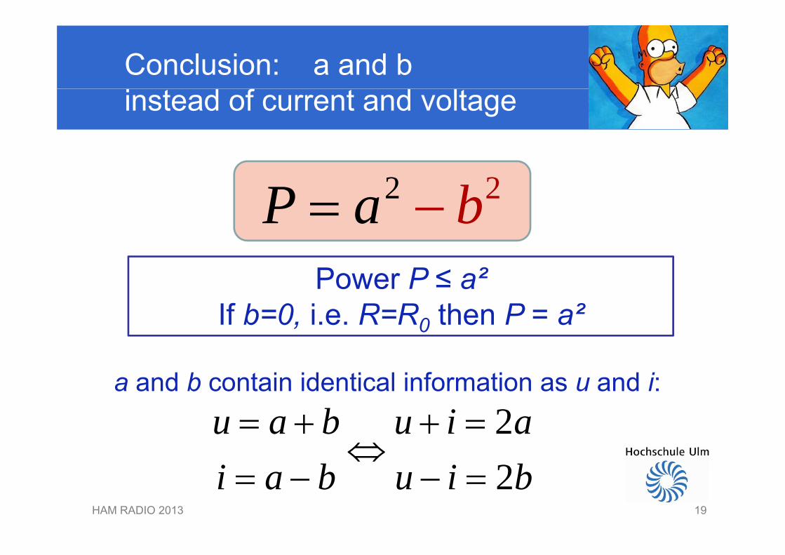
Conclusion: a and b instead of current and voltage
22P ba P baPower P ≤ a²Power P ≤ a²
If b=0, i.e. R=R0 then P = a²
a and b contain identical information as u and i:22
u a b u i ai b i b
HAM RADIO 2013 19
2i a b u i b 19
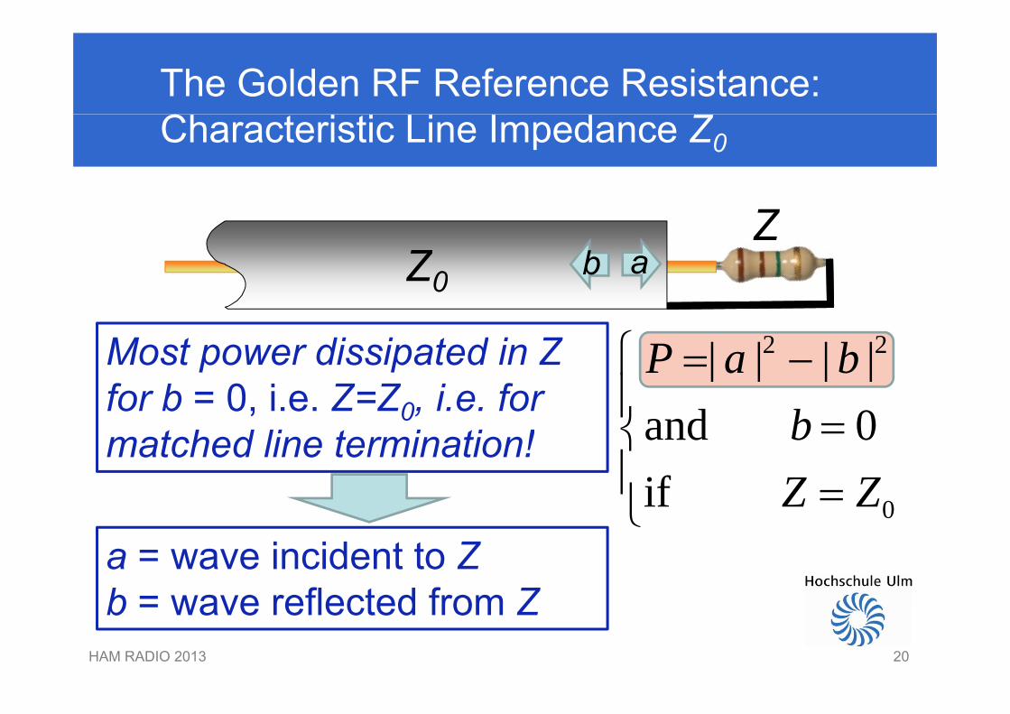
The Golden RF Reference Resistance:Characteristic Line Impedance Z0
Z0
Zab
2 2| | | |P a b
Z0
Most power dissipated in Z | | | |and 0P a b
b
Most power dissipated in Z for b = 0, i.e. Z=Z0, i.e. formatched line termination!
0
and 0if
bZ Z
matched line termination!
a = wave incident to Zb = wave reflected from Z
HAM RADIO 2013 20
b = wave reflected from Z
20
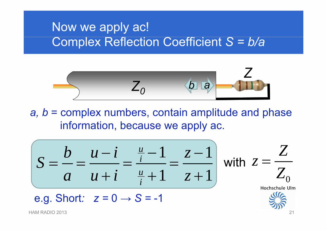
Now we apply ac!Complex Reflection Coefficient S = b/a
Z0
ZabZ0
a, b = complex numbers, contain amplitude and phasea, b complex numbers, contain amplitude and phaseinformation, because we apply ac.
1 1uib u i zS
ZzZ
with1 1u
i
Sa u i z 0Z
Sh 0 S 1HAM RADIO 2013 21
e.g. Short: z = 0 → S = -1
21

We can see a and b using the VNWAE.g. Short Circuit S=-1
a
S = -1 → Reflection with 180° phase lag
( 1)
b
Reflection with 180 phase lag
b
HAM RADIO 2013 2222
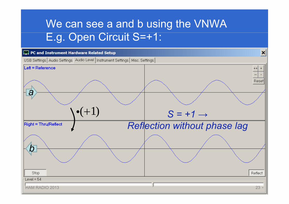
We can see a and b using the VNWAE.g. Open Circuit S=+1:
a
S = +1 → Reflection without phase lag
( 1)
b
Reflection without phase lag
b
HAM RADIO 2013 2323
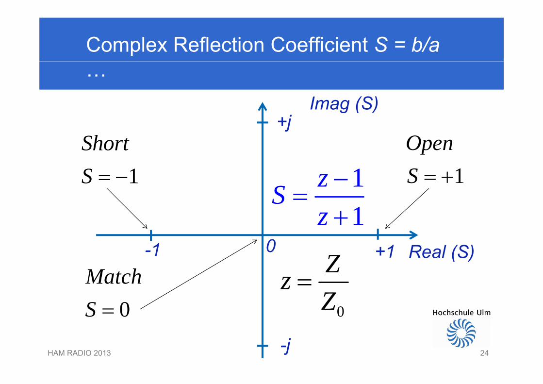
Complex Reflection Coefficient S = b/a …
Imag (S)Imag (S)
Short Open+j
1ShortS 1
OpenS 1zS
1S
z
Real (S)+1-1 0
Match Zz 0
MatchS 0
zZ
HAM RADIO 2013 24-j24
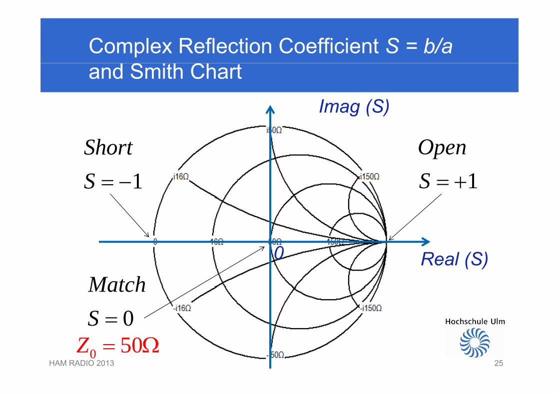
Complex Reflection Coefficient S = b/a and Smith Chart
Imag (S)Imag (S)
Short Open1
ShortS 1
OpenS
0 Real (S)Match
0MatchS
HAM RADIO 2013 250 50Z
25
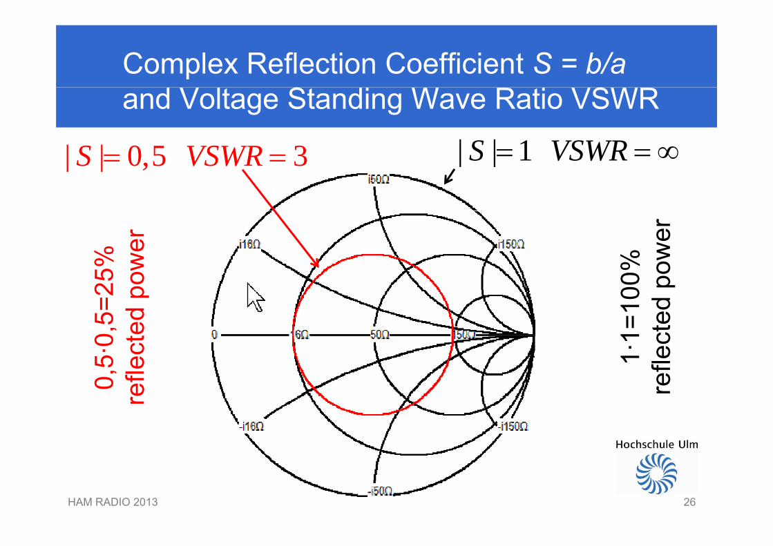
Complex Reflection Coefficient S = b/a and Voltage Standing Wave Ratio VSWR
| | 1S VSWR | | 0 5 3S VSWR | | 1S VSWR | | 0,5 3S VSWR
5%
ower
0%
ower
0,5=
25ed
po
1=10
0ct
edpo
0,5·
0re
flect 1·1
refle
c
r
HAM RADIO 2013 2626
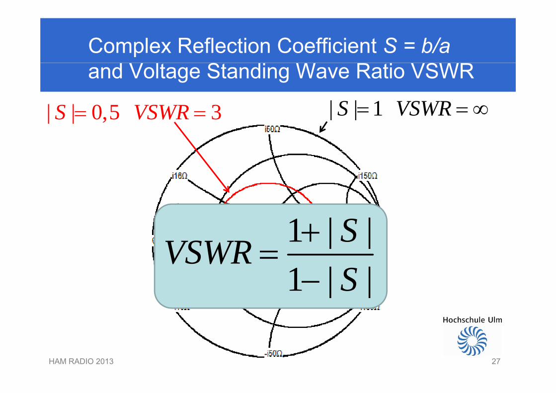
Complex Reflection Coefficient S = b/a and Voltage Standing Wave Ratio VSWR
| | 1S VSWR | | 0 5 3S VSWR | | 1S VSWR | | 0,5 3S VSWR
1 | |SVSWR 1 | |1 | |
SVSWRS
1 | |S
HAM RADIO 2013 2727
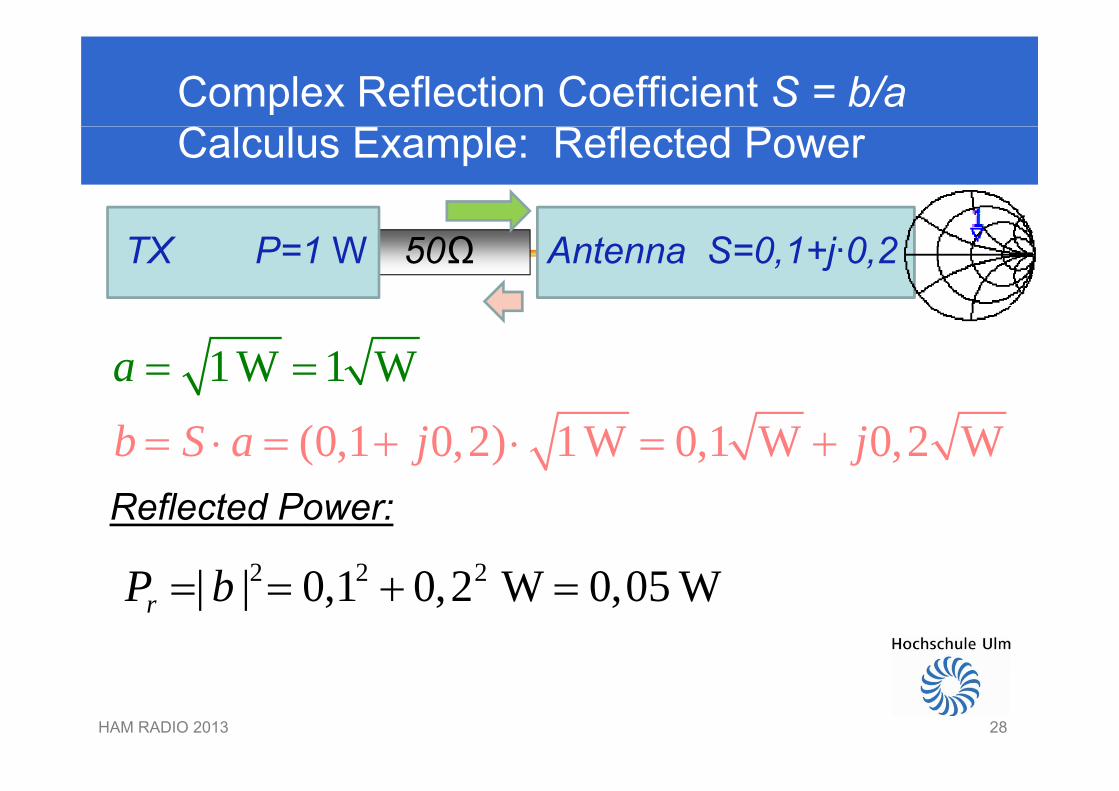
Complex Reflection Coefficient S = b/a Calculus Example: Reflected Power
50ΩTX P=1 W Antenna S=0,1+j·0,2
1 W 1 Wa
(0,1 0,2) 1W 0,1 W 0,2 Wb S a j j Reflected Power:
2 2 2| | 0 1 0 2 W 0 05 WP b 2 2 2| | 0,1 0,2 W 0,05 WrP b
HAM RADIO 2013 2828
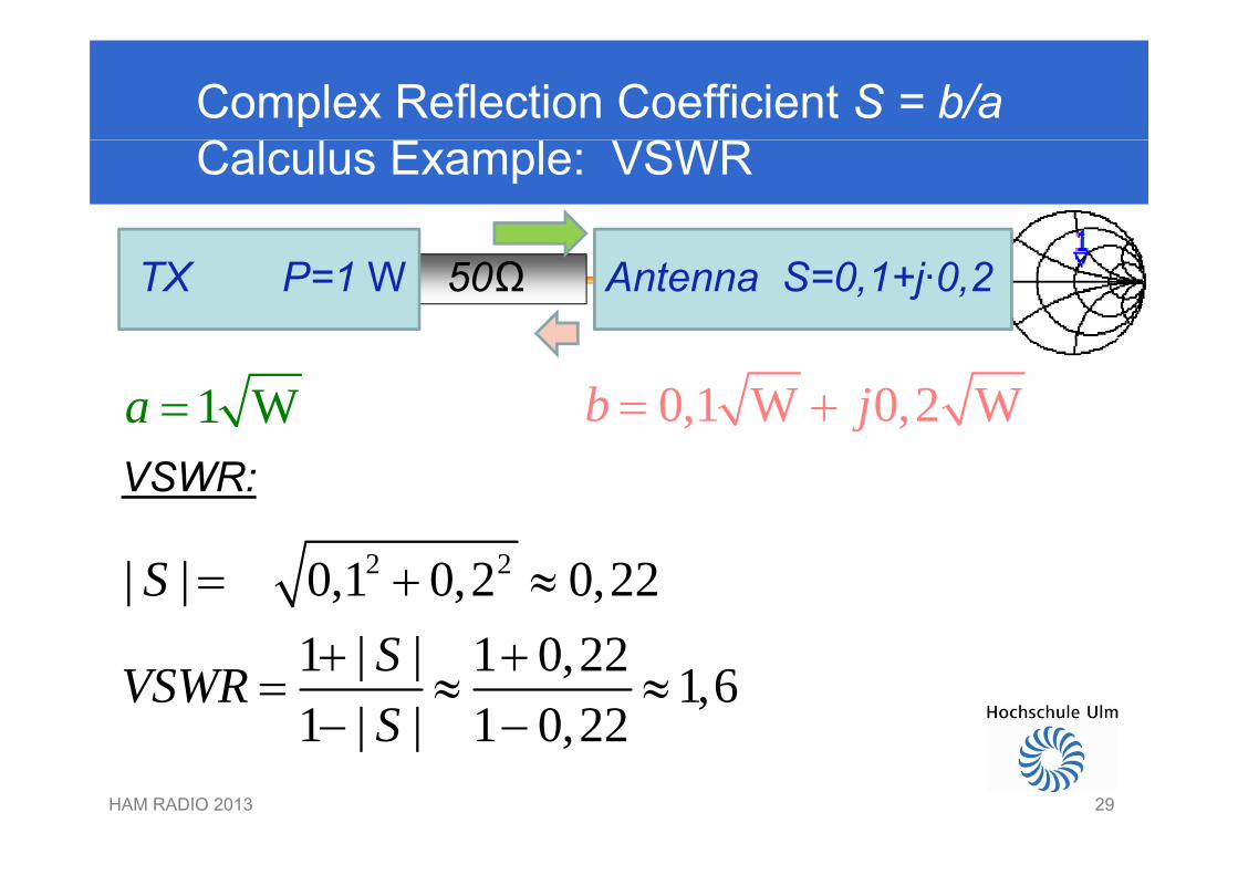
Complex Reflection Coefficient S = b/a Calculus Example: VSWR
50ΩTX P=1 W Antenna S=0,1+j·0,2
1 Wa 0,1 W 0,2 Wb j VSWR:
2 2| | 0,1 0,2 0,22| |
S 1 | | 1 0,22 1,61 | | 1 0 22
SVSWRS
HAM RADIO 2013 29
1 | | 1 0,22S
29
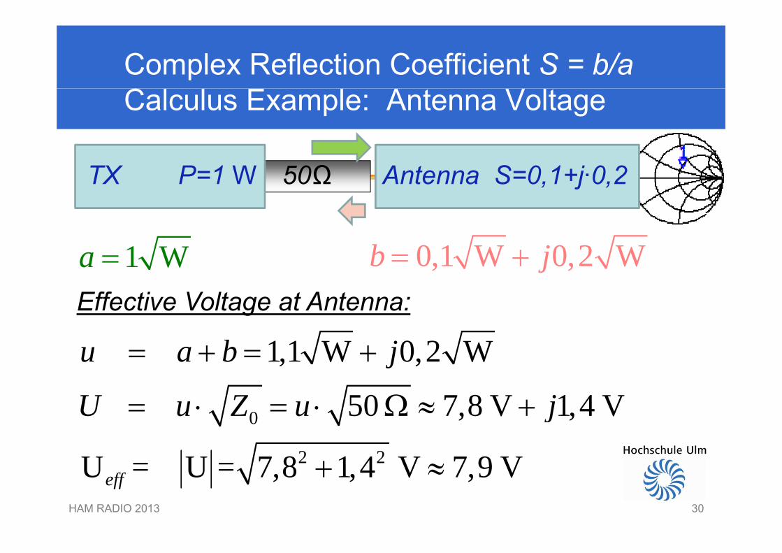
Complex Reflection Coefficient S = b/a Calculus Example: Antenna Voltage
50ΩTX P=1 W Antenna S=0,1+j·0,2
0,1 W 0,2 Wb j 1 Wa Effective Voltage at Antenna:
1,1 W 0,2 W
50 7 8 V 1 4 V
u a b j
U u Z u j
0
2 2
50 7,8 V 1,4 V
U = U = 7 8 1 4 V 7 9 V
U u Z u j
HAM RADIO 2013 30
U = U = 7,8 1,4 V 7,9 Veff
30
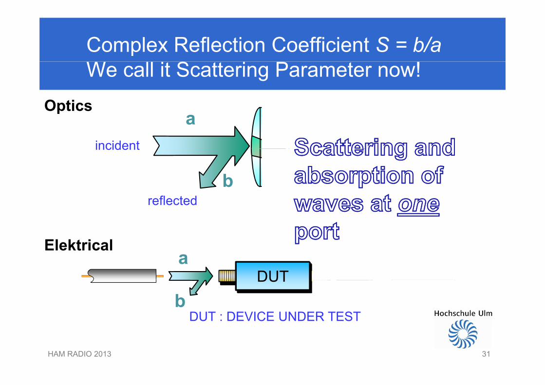
Complex Reflection Coefficient S = b/a We call it Scattering Parameter now!
Optics
incident
Opticsa
b2incidentdurchgehend
breflected
DUT
Elektricala
DUT
DUT : DEVICE UNDER TEST b
HAM RADIO 2013 3131
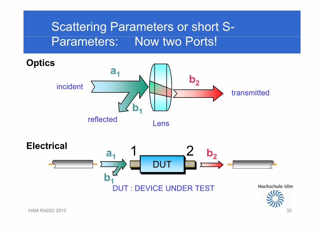
Scattering Parameters or short S-Parameters: Now two Ports!
Optics
incident
Opticsa1 b2incident
transmitted
b1reflected Lens
DUT
Electrical 1 2a1 b2DUT
DUT : DEVICE UNDER TEST b1
HAM RADIO 2013 3232
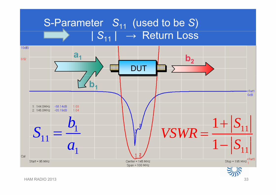
S-Parameter S11 (used to be S)| S11 | → Return Loss
aDUT
a1 b2
b1
b 1 S111
bS 1111
SVSWR
S
1a 111 S
HAM RADIO 2013 3333
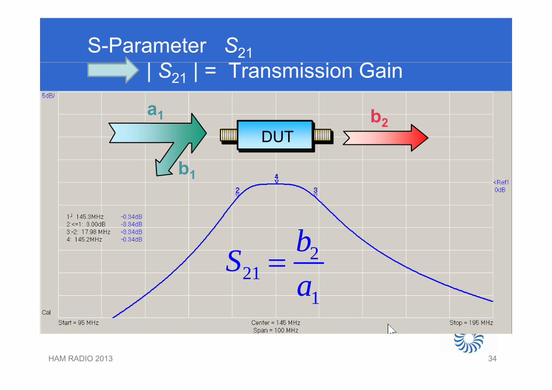
S-Parameter S21| S21 | = Transmission Gain
aDUT
a1 b2
b1
b221
bSa
1a
HAM RADIO 2013 3434
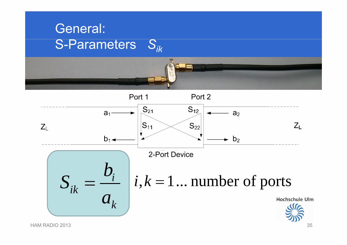
General:S-Parameters Sik
P t 1 P t 2Port 1 Port 2
ibS 1 b f ti k
2-Port Device
iik
k
Sa
, 1... number of portsi k
HAM RADIO 2013 35
k
35
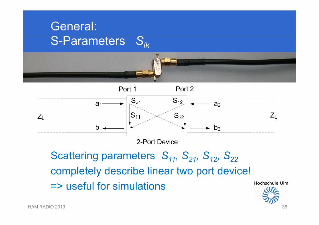
General:S-Parameters Sik
P t 1 P t 2Port 1 Port 2
Scattering parameters S11, S21, S12, S22
2-Port Device
completely describe linear two port device!=> useful for simulations
HAM RADIO 2013 36
useful for simulations
36

BREAK ???BREAK ???
HAM RADIO 2013 3737
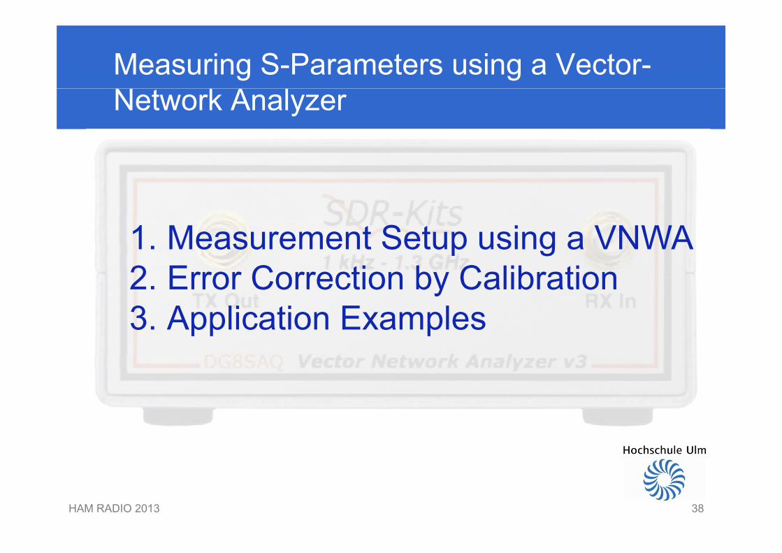
Measuring S-Parameters using a Vector-Network Analyzer
1. Measurement Setup using a VNWA2 Error Correction by Calibration2. Error Correction by Calibration3. Application Examples
HAM RADIO 2013 3838
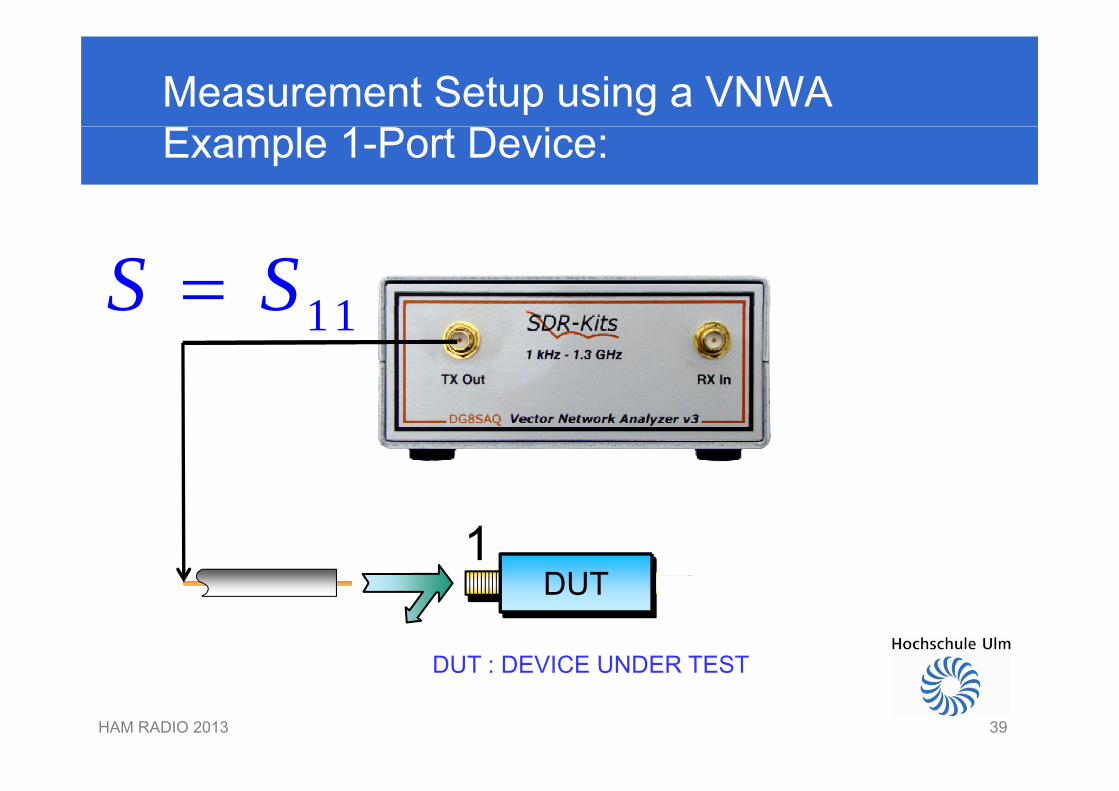
Measurement Setup using a VNWAExample 1-Port Device:
11S S 11S S
DUT1
DUT
DUT : DEVICE UNDER TEST
HAM RADIO 2013 39
DUT : DEVICE UNDER TEST
39
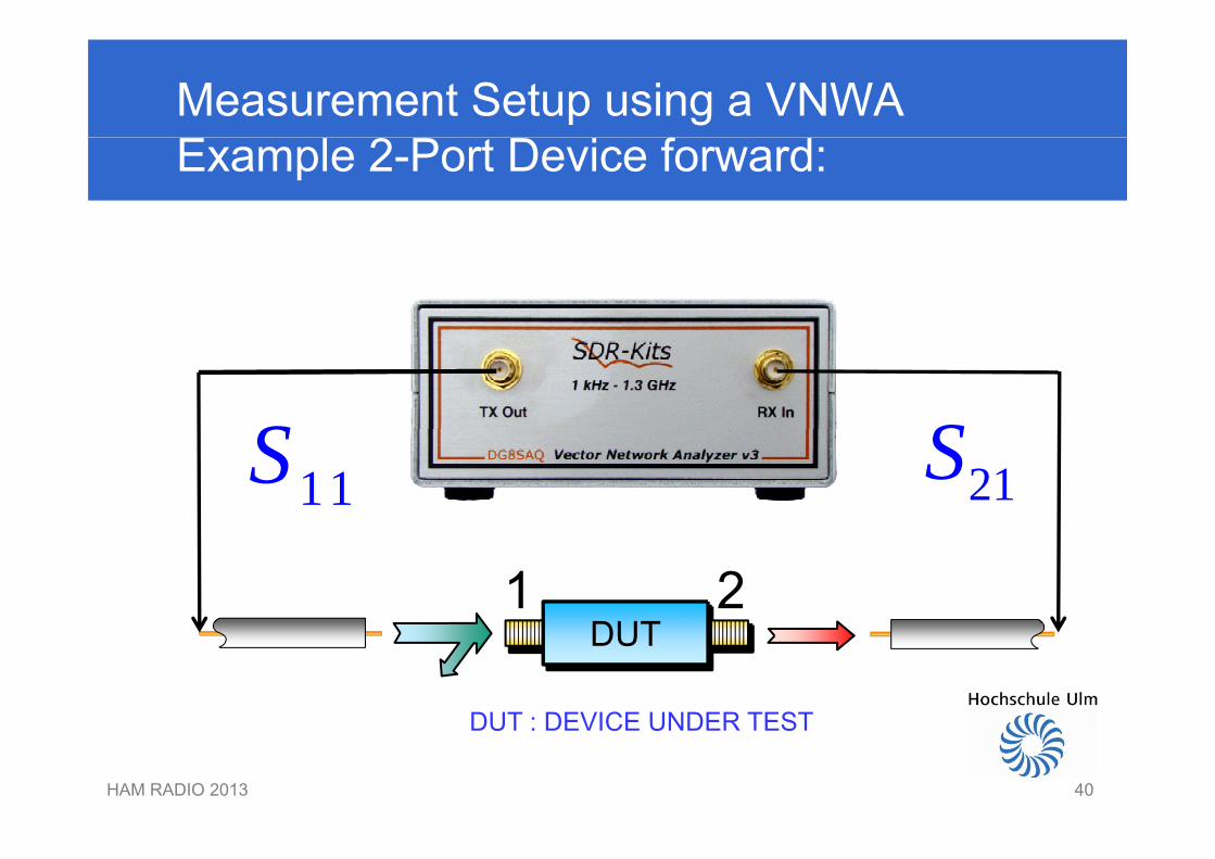
Measurement Setup using a VNWAExample 2-Port Device forward:
S S11S 21S
DUT1 2
DUT
DUT : DEVICE UNDER TEST
HAM RADIO 2013 40
DUT : DEVICE UNDER TEST
40
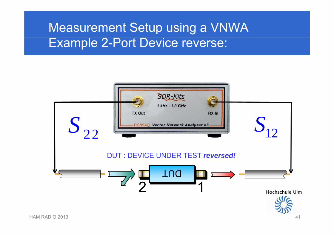
Measurement Setup using a VNWAExample 2-Port Device reverse:
S S22S 12S
DUT
DUT : DEVICE UNDER TEST reversed!
DUT
12
HAM RADIO 2013 4141
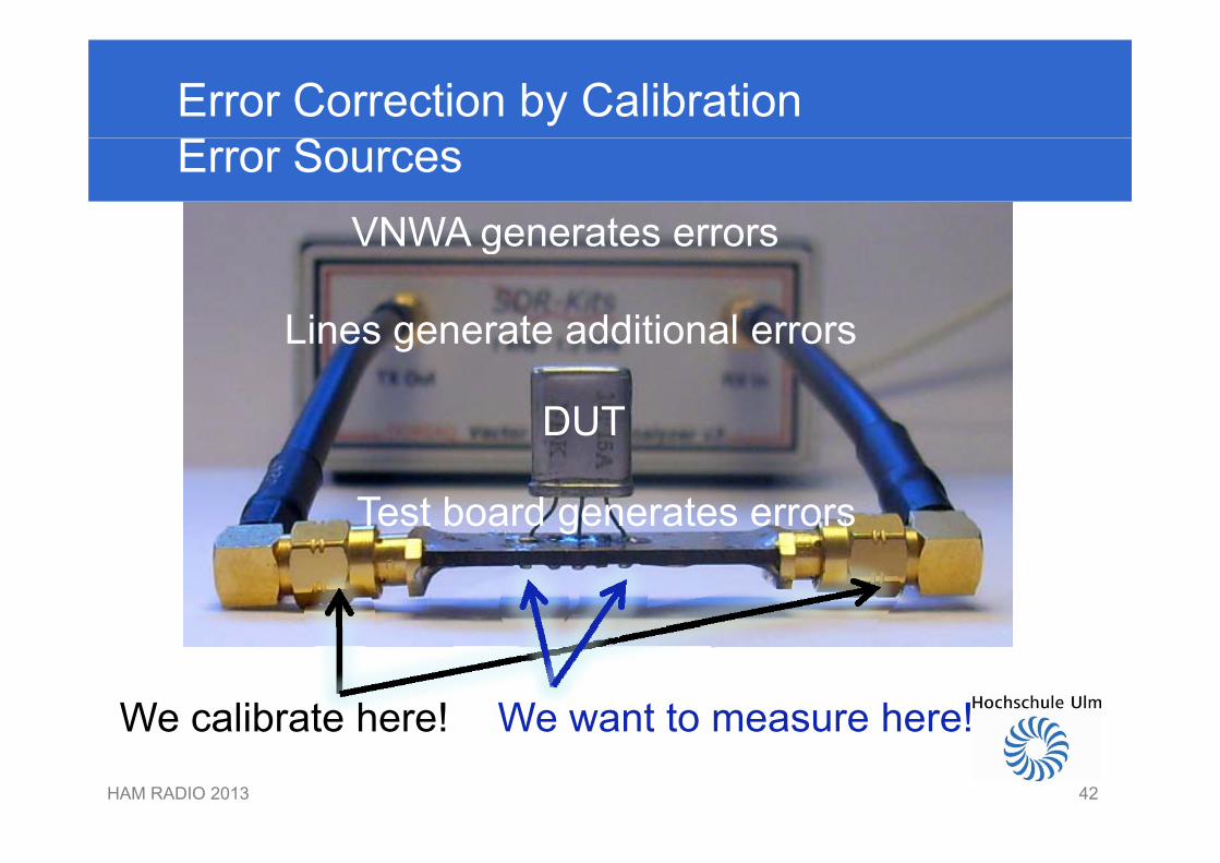
Error Correction by CalibrationError Sources
VNWA generates errorsVNWA generates errors
Lines generate additional errorsLines generate additional errors
DUTDUT
Test board generates errorsg
We calibrate here! We want to measure here!
HAM RADIO 2013 42
We calibrate here! We want to measure here!
42
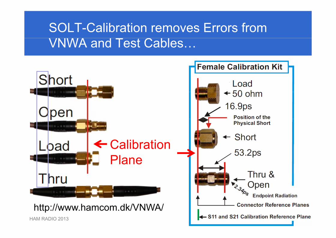
SOLT-Calibration removes Errors fromVNWA and Test Cables…
CalibrationCalibrationPlane
HAM RADIO 2013 43
http://www.hamcom.dk/VNWA/
43
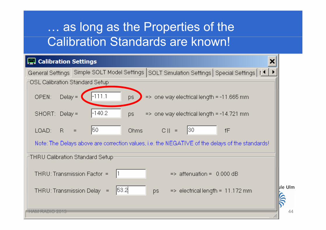
… as long as the Properties of theCalibration Standards are known!
HAM RADIO 2013 4444
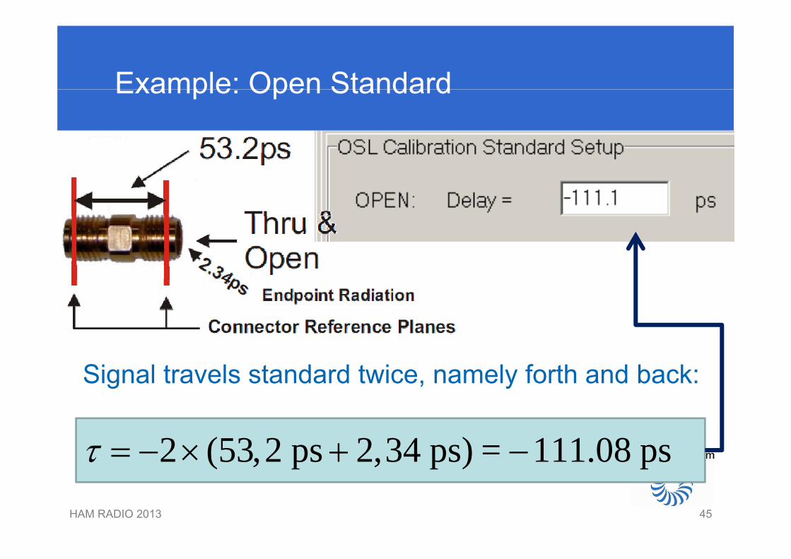
Example: Open StandardExample: Open Standard
Signal travels standard twice, namely forth and back:
2 (53,2 ps 2,34 ps) = 111.08 ps
HAM RADIO 2013 4545
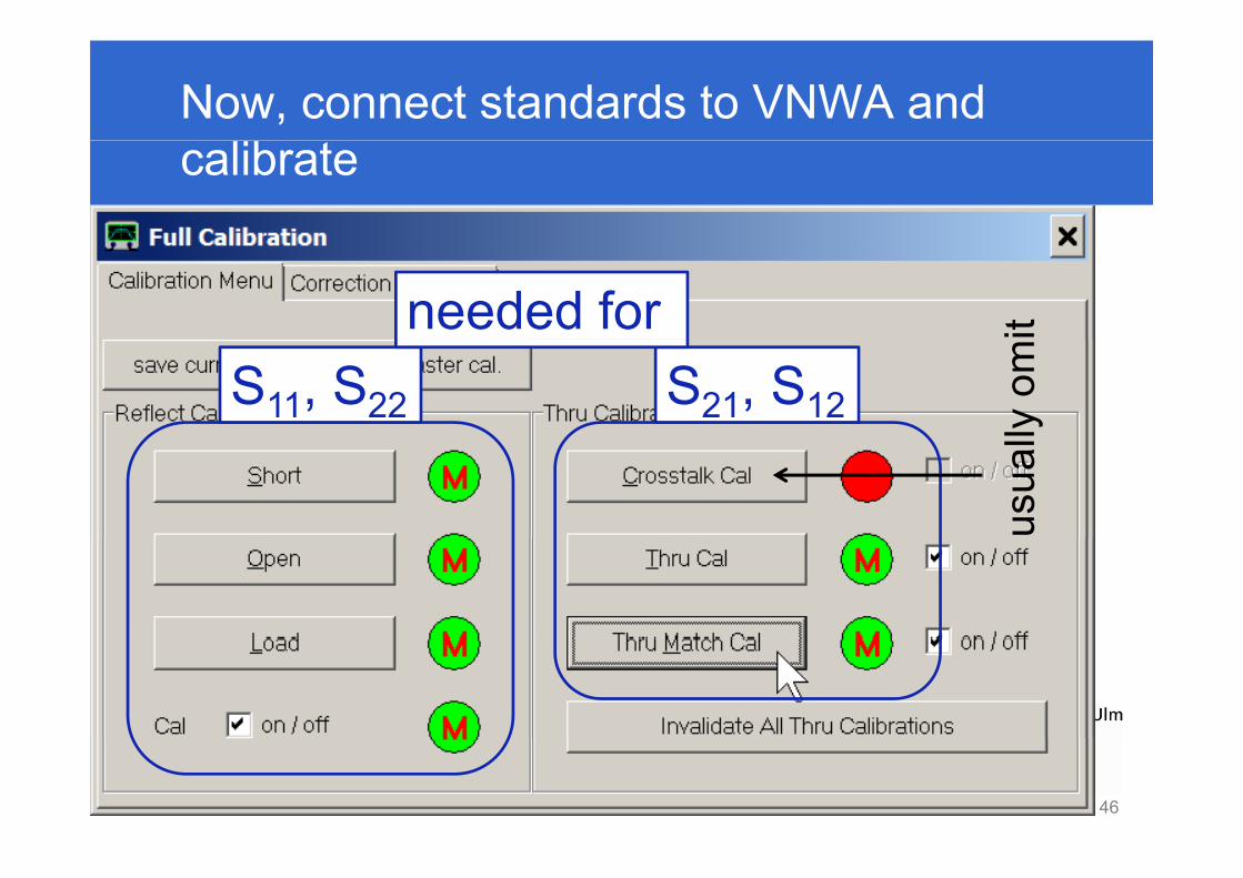
Now, connect standards to VNWA andcalibrate
needed for it
S11, S22 S21, S12 lyom
usua
l
HAM RADIO 2013 4646
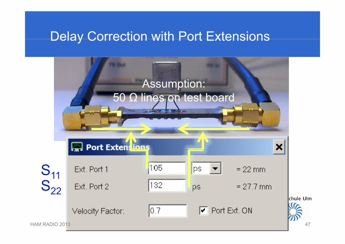
Delay Correction with Port ExtensionsDelay Correction with Port Extensions
Assumption:50 Ω li t t b d50 Ω lines on test board
S1111S22
HAM RADIO 2013 4747
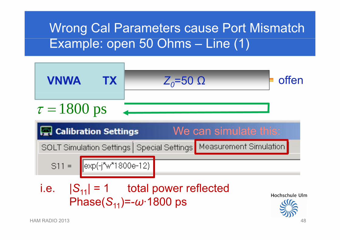
Wrong Cal Parameters cause Port MismatchExample: open 50 Ohms – Line (1)
offenVNWA TX Z0=50 Ω
1800 ps We can simulate this:
i.e. |S11| = 1 total power reflectedPhase(S )= ω·1800 ps
HAM RADIO 2013 48
Phase(S11)=-ω·1800 ps
48
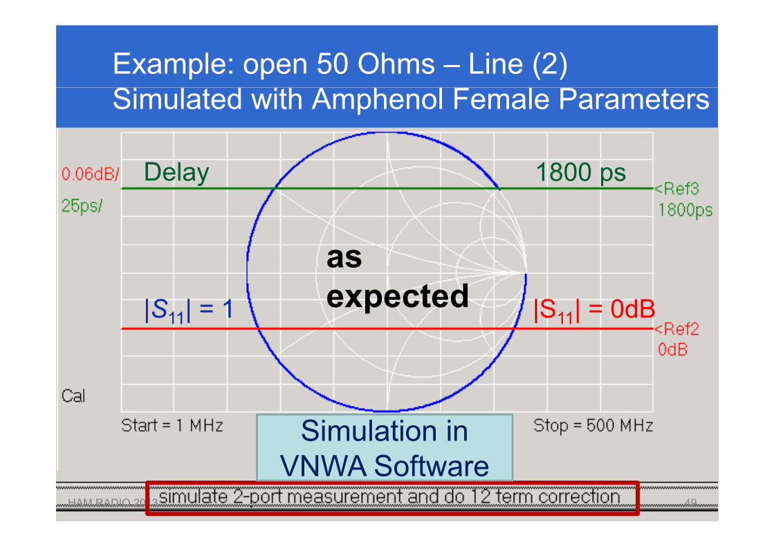
Example: open 50 Ohms – Line (2) Simulated with Amphenol Female Parameters
1800 psDelay
as|S11| = 1 |S11| = 0dBexpected
Simulation in VNWA S ft
HAM RADIO 2013 49
VNWA Software49
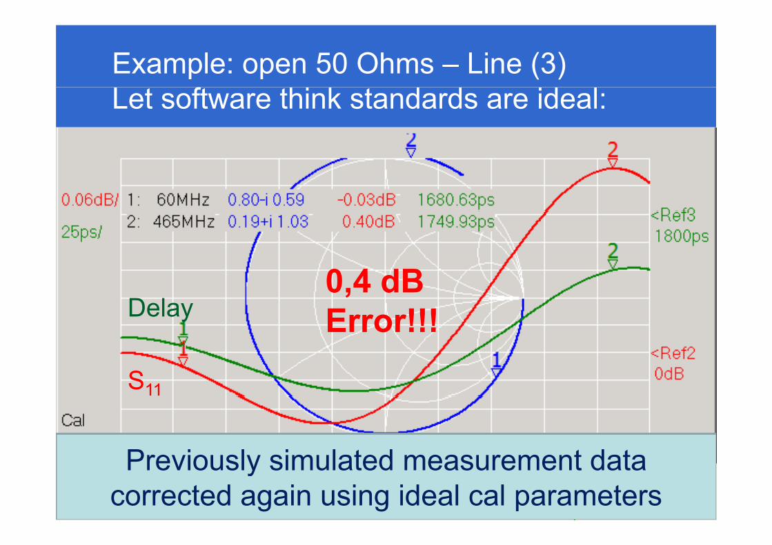
Example: open 50 Ohms – Line (3) Let software think standards are ideal:
0 4 dBDelay
0,4 dB Error!!!
S11
Previously simulated measurement dataHAM RADIO 2013 50
Previously simulated measurement datacorrected again using ideal cal parameters
50
ApplicationsApplications …
HAM RADIO 2013 5151
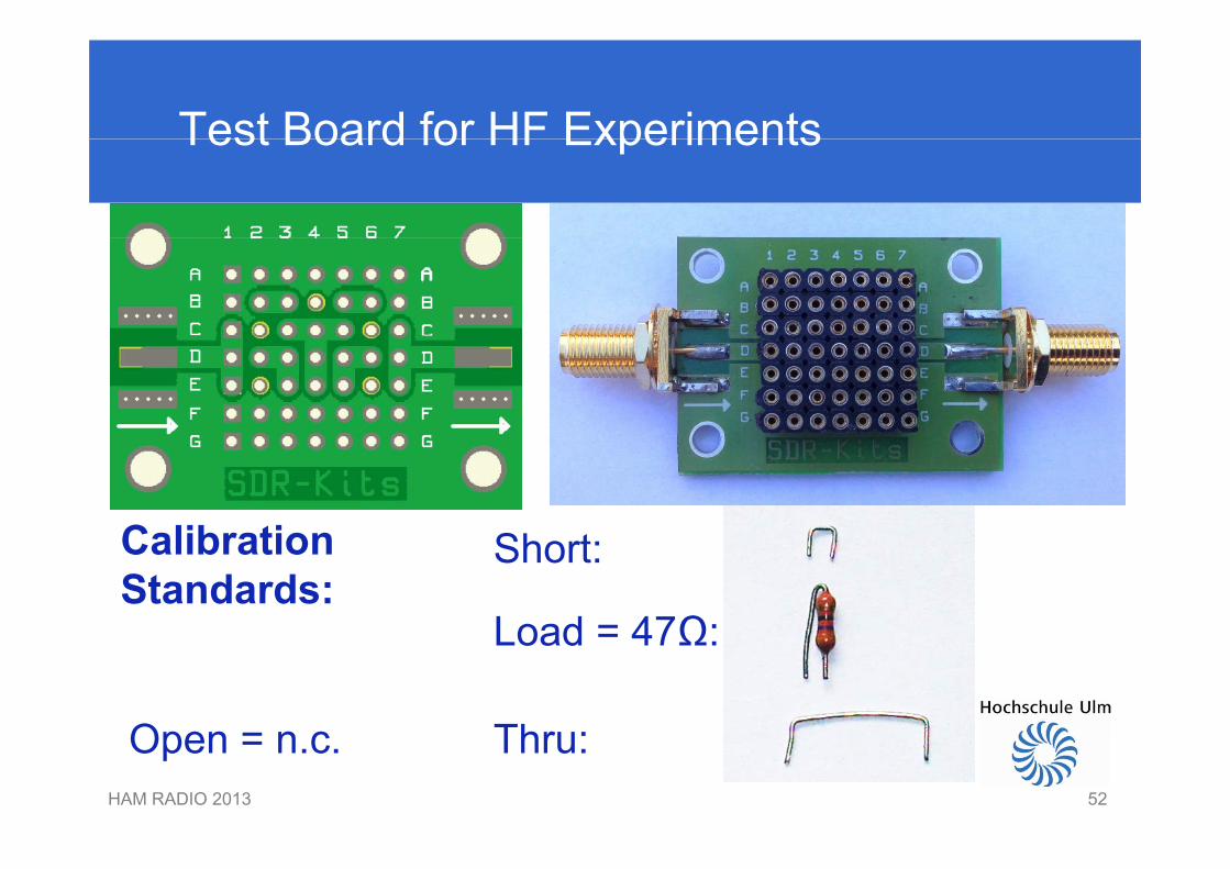
Test Board for HF ExperimentsTest Board for HF Experiments
Calibration ShCalibrationStandards:
Short:
Load = 47Ω:Load = 47Ω:
ThOHAM RADIO 2013 52
Thru:Open = n.c.
52
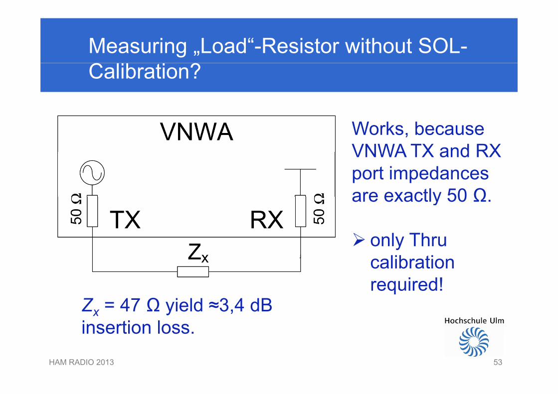
Measuring „Load“-Resistor without SOL-Calibration?
Works, becauseVNWA TX and RXVNWA TX and RX port impedancesare exactly 50 Ωare exactly 50 Ω.
only Thru only Thrucalibrationrequired!
Zx = 47 Ω yield ≈3,4 dBinsertion loss
required!
HAM RADIO 2013 53
insertion loss.
53
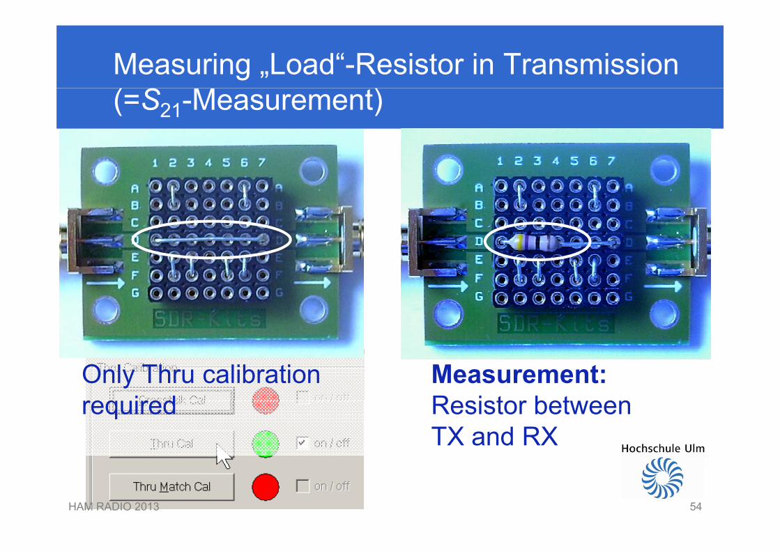
Measuring „Load“-Resistor in Transmission (=S21-Measurement)
Only Thru calibrationrequired
Measurement: Resistor betweenrequired Resistor betweenTX and RX
HAM RADIO 2013 5454
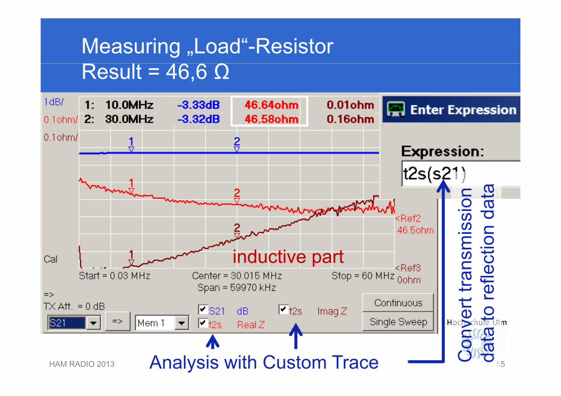
Measuring „Load“-ResistorResult = 46,6 Ω
n tam
issi
oon
dat
inductive part
trans
mef
lect
ionv
ertt
ato
re
HAM RADIO 2013 55Analysis with Custom Trace Con
data
55
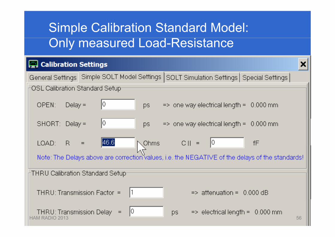
Simple Calibration Standard Model:Only measured Load-Resistance
HAM RADIO 2013 5656

SOL-Calibration for S11-MeasurementSOL Calibration for S11 Measurement
TX
Short Open Loadp
HAM RADIO 2013 5757
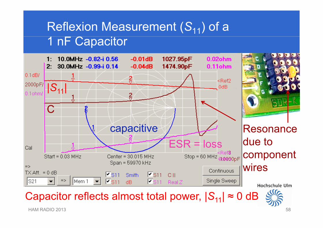
Reflexion Measurement (S11) of a1 nF Capacitor
|S |
C
|S11|
Resonancedue toESR l
capacitivedue tocomponentwires
ESR = loss
wires
HAM RADIO 2013 58
Capacitor reflects almost total power, |S11| ≈ 0 dB
58
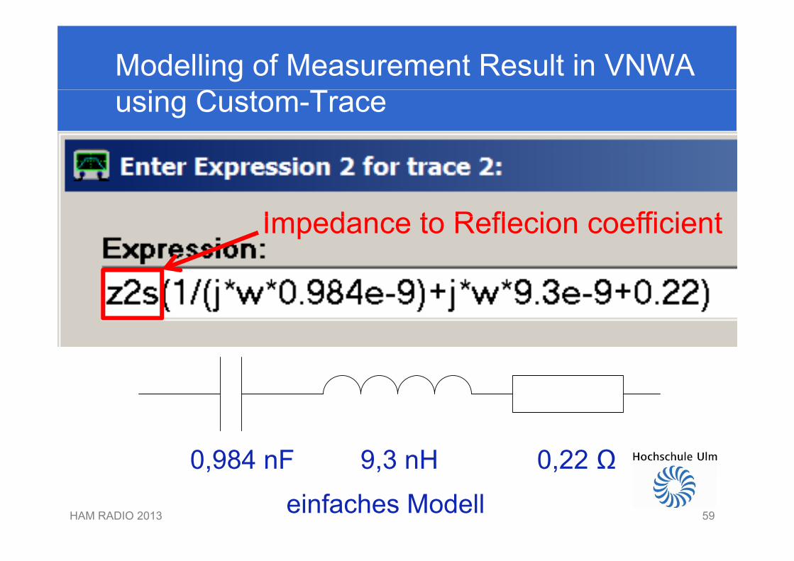
Modelling of Measurement Result in VNWA using Custom-Trace
I d t R fl i ffi i tImpedance to Reflecion coefficient
0,984 nF 9,3 nH 0,22 Ω
HAM RADIO 2013 59
, , ,
einfaches Modell59
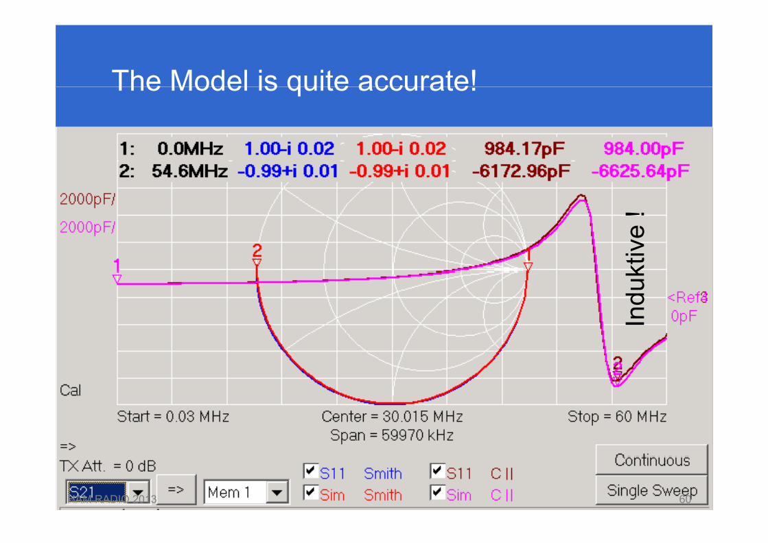
The Model is quite accurate!The Model is quite accurate!
ktiv
e !
Indu
k
HAM RADIO 2013 6060
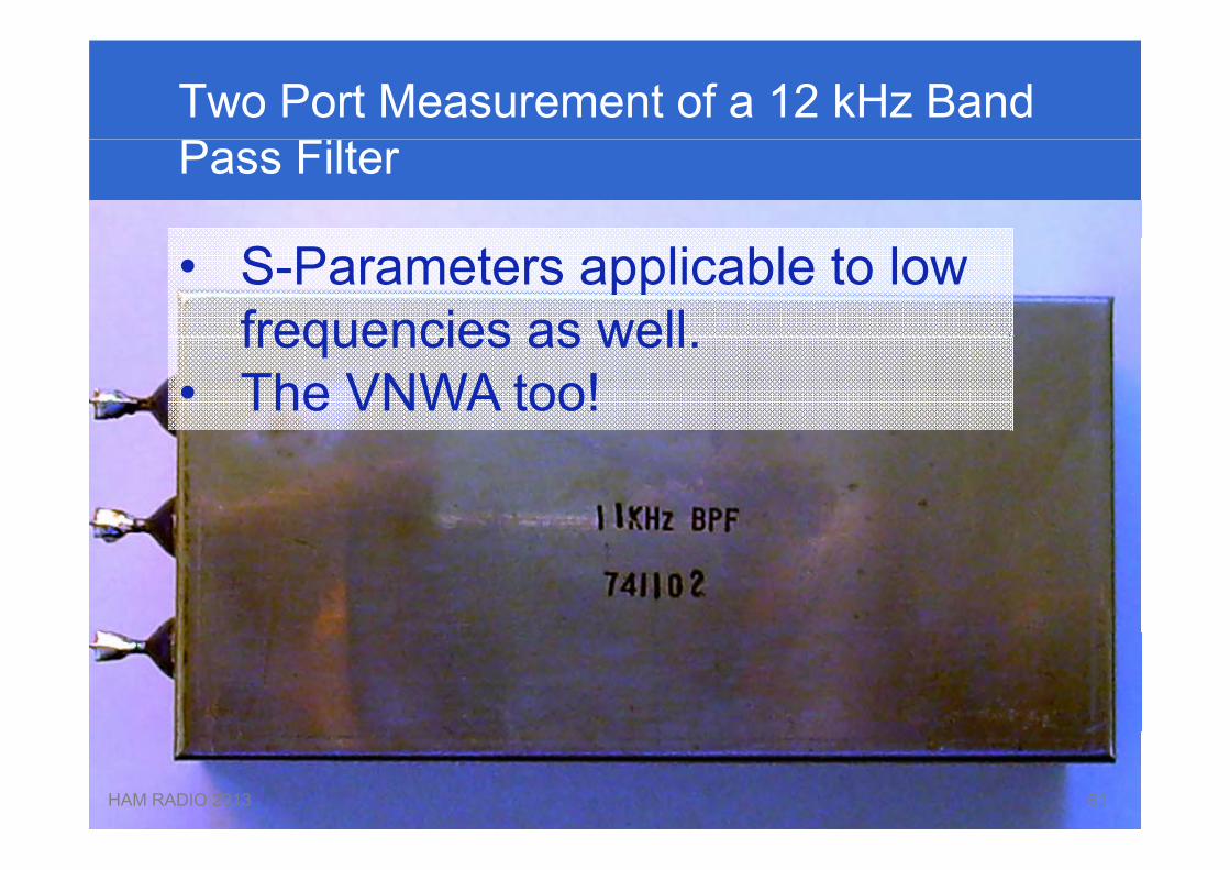
Two Port Measurement of a 12 kHz Band Pass Filter
• S-Parameters applicable to lowfrequencies as wellfrequencies as well.
• The VNWA too!
HAM RADIO 2013 6161
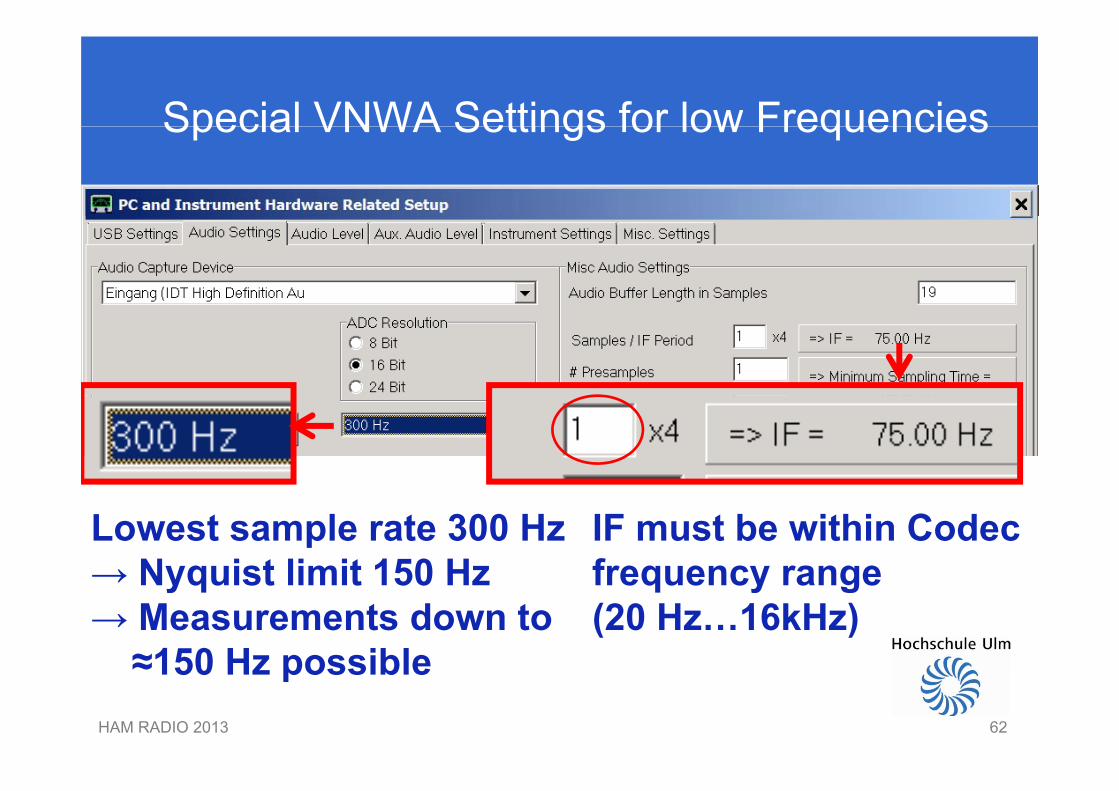
Special VNWA Settings for low FrequenciesSpecial VNWA Settings for low Frequencies
Lowest sample rate 300 Hz→ Nyquist limit 150 Hz
IF must be within Codec frequency range→ Nyquist limit 150 Hz
→ Measurements down to≈150 Hz possible
frequency range(20 Hz…16kHz)
HAM RADIO 2013 62
≈150 Hz possible
62
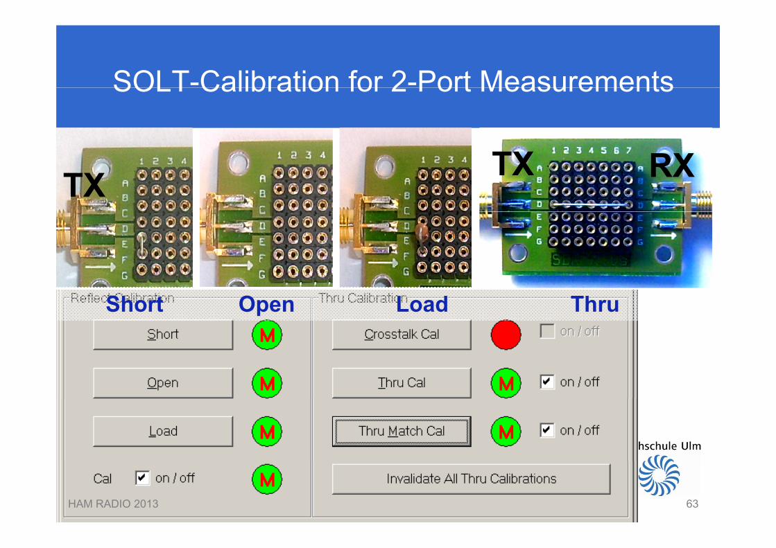
SOLT-Calibration for 2-Port MeasurementsSOLT Calibration for 2 Port Measurements
TX TX RX
Short Open Load Thru
HAM RADIO 2013 6363
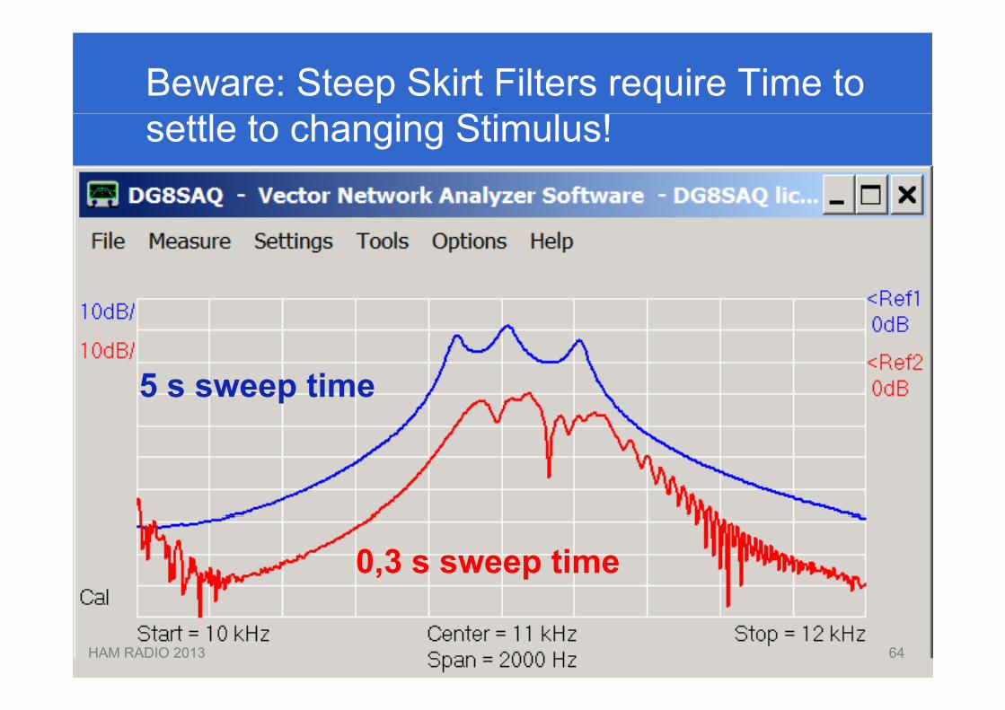
Beware: Steep Skirt Filters require Time tosettle to changing Stimulus!
5 s sweep time
0,3 s sweep time
HAM RADIO 2013 6464
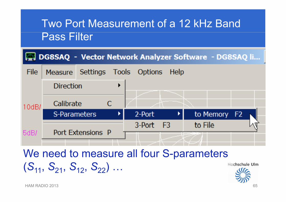
Two Port Measurement of a 12 kHz Band Pass Filter
We need to measure all four S-parameters(S11, S21, S12, S22) …HAM RADIO 2013 65
(S11, S21, S12, S22) …
65

Two Port Measurement of a 12 kHz Band Pass Filter: Forward Measurement
TX
1
2
RXHAM RADIO 2013 66
RXS11, S21 measured
66
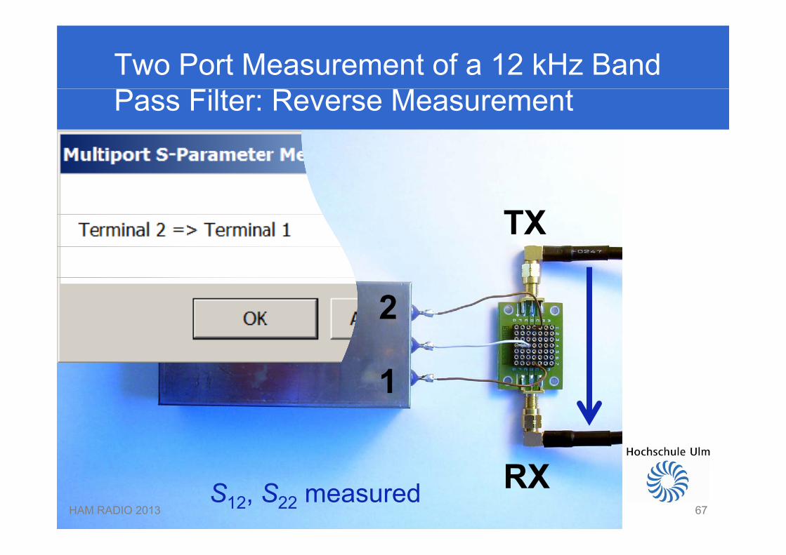
Two Port Measurement of a 12 kHz Band Pass Filter: Reverse Measurement
TXTX
2
1
RXHAM RADIO 2013 67
RXS12, S22 measured67

What are measured 2-Port S-Parameters good for?
Optimum Match?p
HAM RADIO 2013 6868
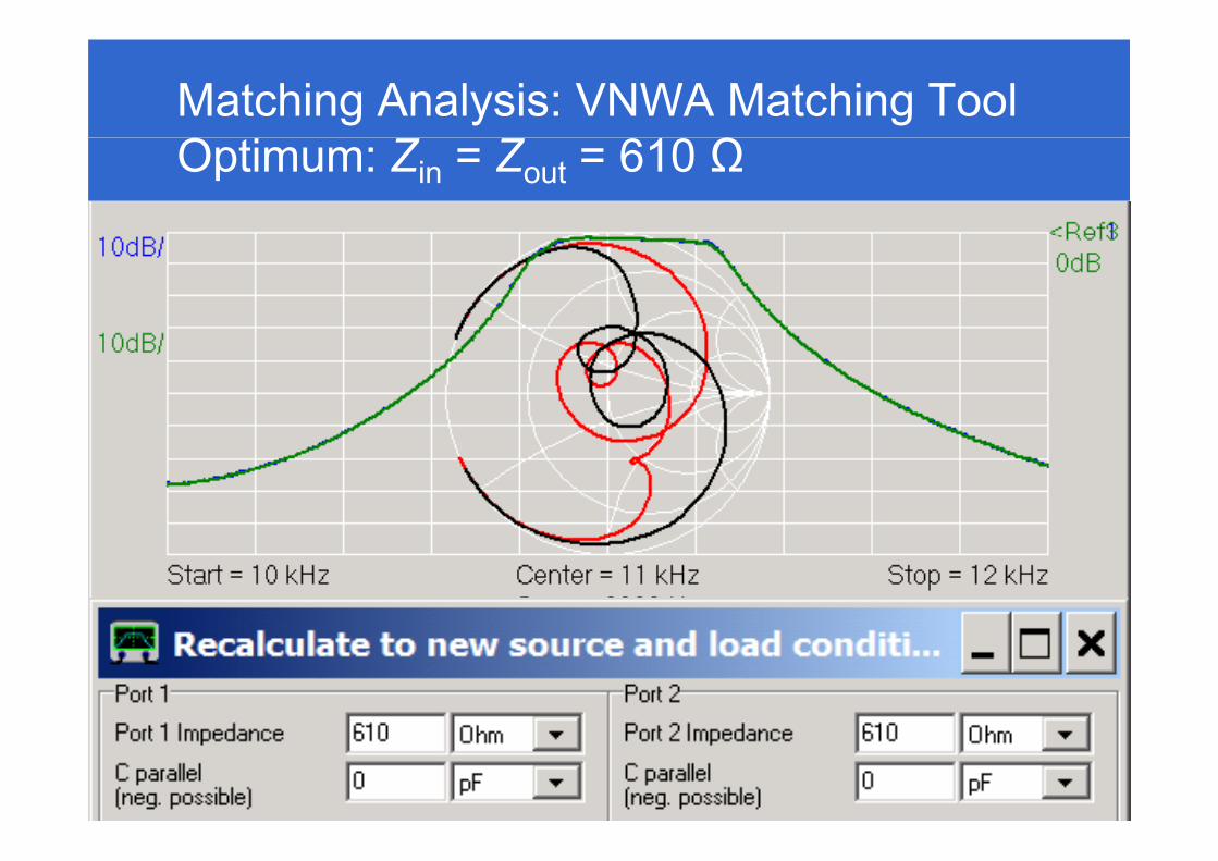
Matching Analysis: VNWA Matching ToolOptimum: Zin = Zout = 610 Ω
HAM RADIO 2013 6969
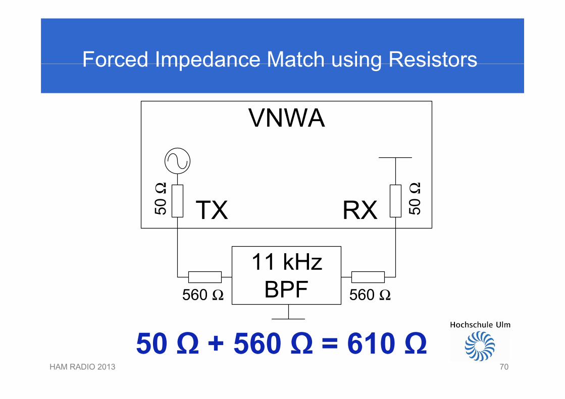
Forced Impedance Match using ResistorsForced Impedance Match using Resistors
50 Ω 560 Ω 610 ΩHAM RADIO 2013 70
50 Ω + 560 Ω = 610 Ω70
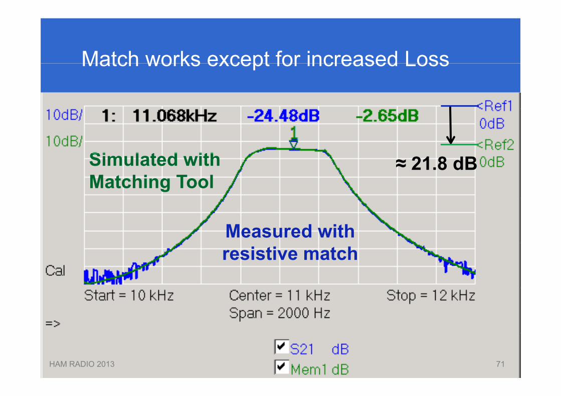
Match works except for increased LossMatch works except for increased Loss
Si l t d ithSimulated withMatching Tool
≈ 21.8 dB
Measured withresistive match
HAM RADIO 2013 7171
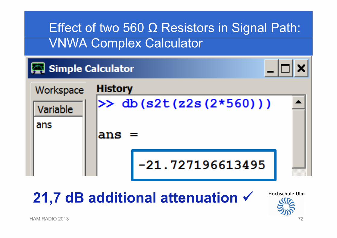
Effect of two 560 Ω Resistors in Signal Path: VNWA Complex Calculator
21 7 dB additional attenuation HAM RADIO 2013 72
21,7 dB additional attenuation 72
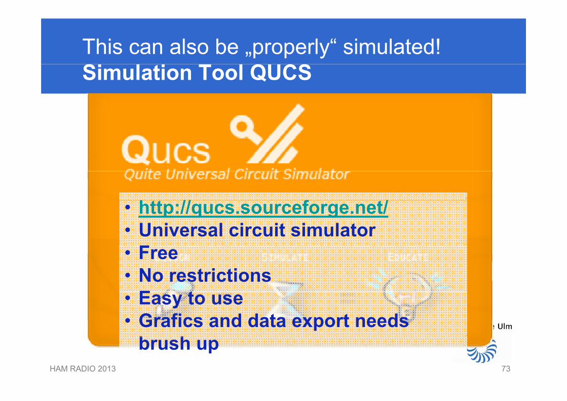
This can also be „properly“ simulated!Simulation Tool QUCS
htt // f t/• http://qucs.sourceforge.net/• Universal circuit simulator
F• Free• No restrictions
E t• Easy to use• Grafics and data export needs
b hHAM RADIO 2013 73
brush up
73
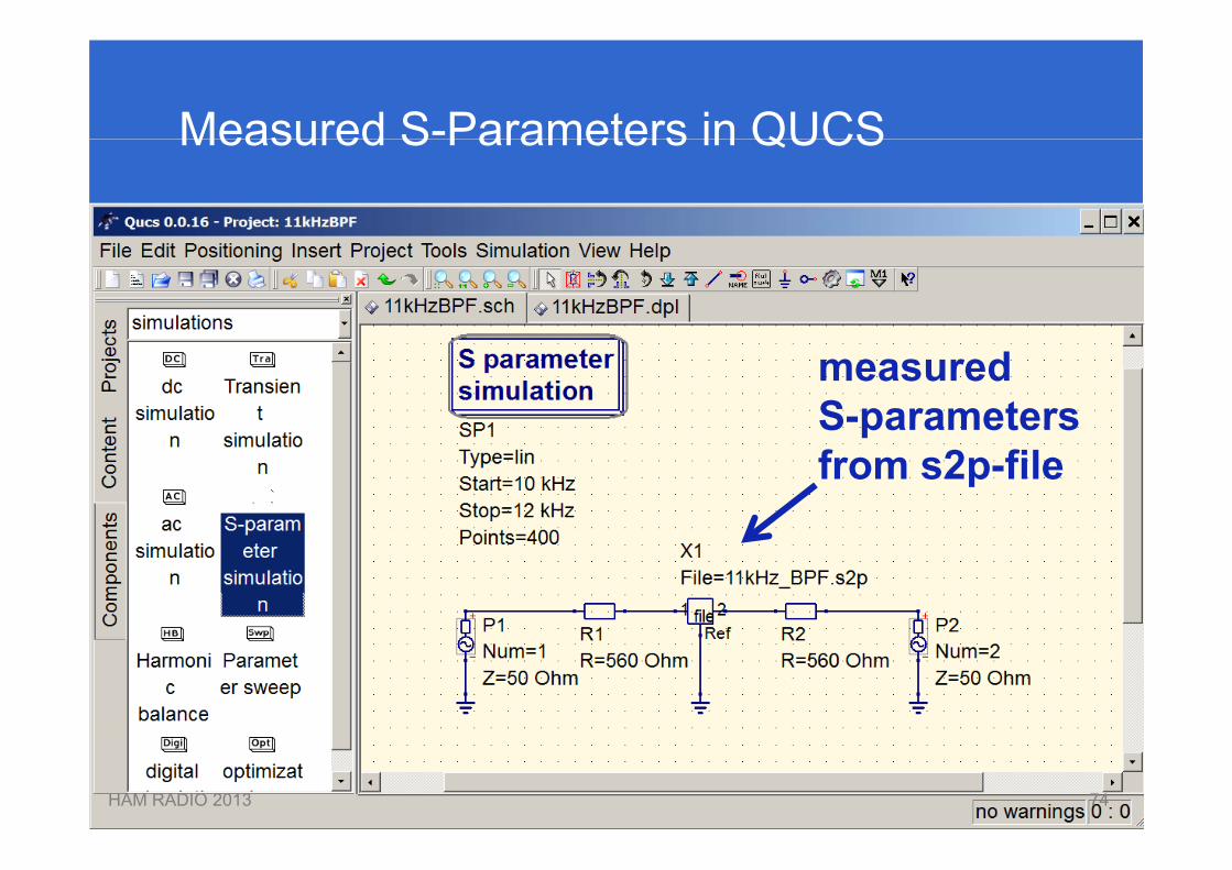
Measured S-Parameters in QUCSMeasured S Parameters in QUCS
measuredS-parameterspfrom s2p-file
HAM RADIO 2013 7474
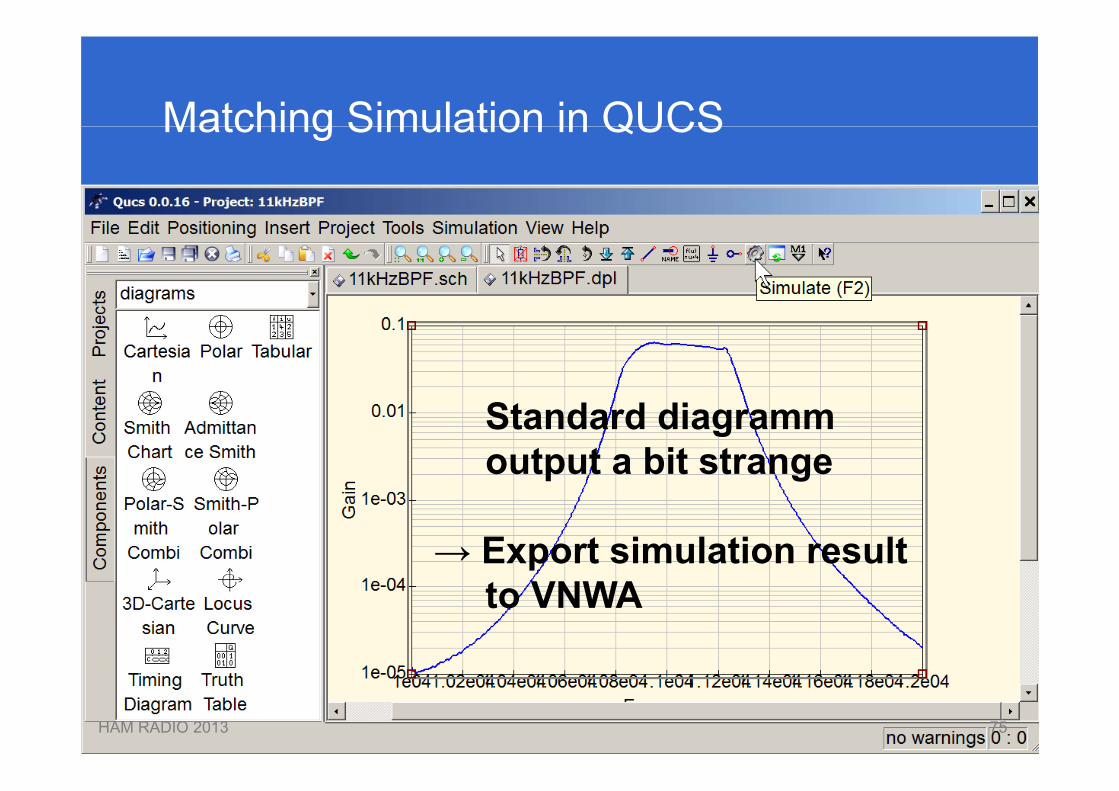
Matching Simulation in QUCSMatching Simulation in QUCS
Standard diagrammoutput a bit strange
→ Export simulation resultto VNWA
HAM RADIO 2013 7575
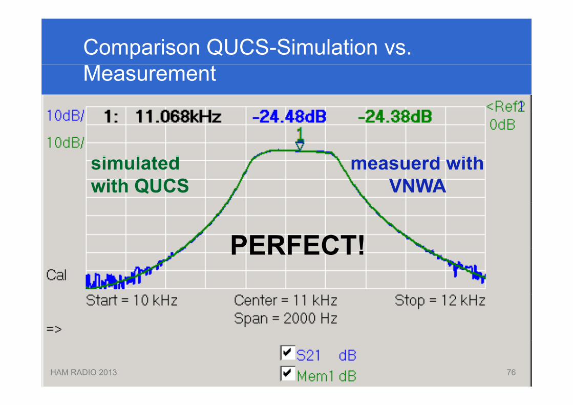
Comparison QUCS-Simulation vs. Measurement
d ithi l t d measuerd withVNWA
simulatedwith QUCS
PERFECT!PERFECT!
HAM RADIO 2013 7676
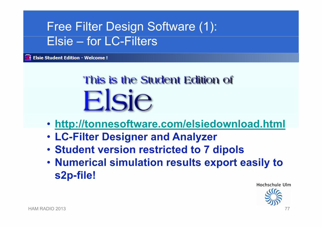
Free Filter Design Software (1): Elsie – for LC-Filters
• http://tonnesoftware.com/elsiedownload.html• LC-Filter Designer and AnalyzerLC Filter Designer and Analyzer• Student version restricted to 7 dipols• Numerical simulation results export easily toNumerical simulation results export easily to
s2p-file!
HAM RADIO 2013 7777

Free Filter Design Software (2): Dishal – for Crystal Filters
• http://www.bartelsos.de/dk7jb.php/quarzfilter-horst dj6evhorst-dj6ev
• Crystal filter designer and analyzer• Simulates without crystal losses• Simulates without crystal losses• S21-simulation results can be exported
HAM RADIO 2013 7878
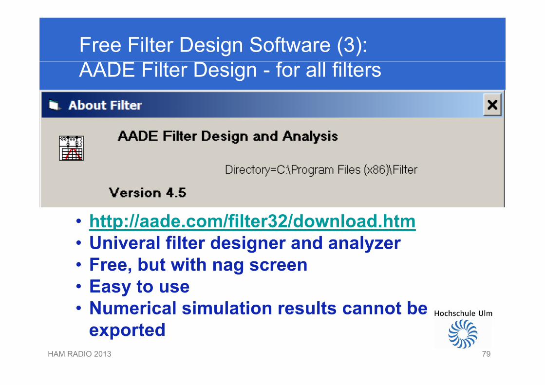
Free Filter Design Software (3):AADE Filter Design - for all filters
• http://aade.com/filter32/download.htm U i l filt d i d l• Univeral filter designer and analyzer
• Free, but with nag screenE t• Easy to use
• Numerical simulation results cannot bet d
HAM RADIO 2013 79
exported
79
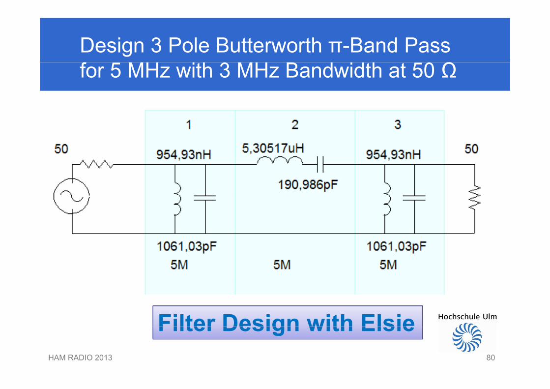
Design 3 Pole Butterworth π-Band Pass for 5 MHz with 3 MHz Bandwidth at 50 Ω
Filter Design with ElsieHAM RADIO 2013 80
Filter Design with Elsie80
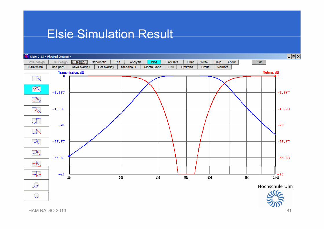
Elsie Simulation ResultElsie Simulation Result
HAM RADIO 2013 8181
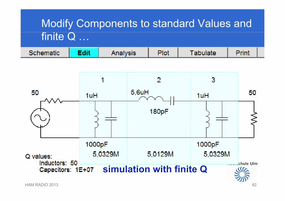
Modify Components to standard Values andfinite Q …
simulation with finite QHAM RADIO 2013 82
simulation with finite Q
82
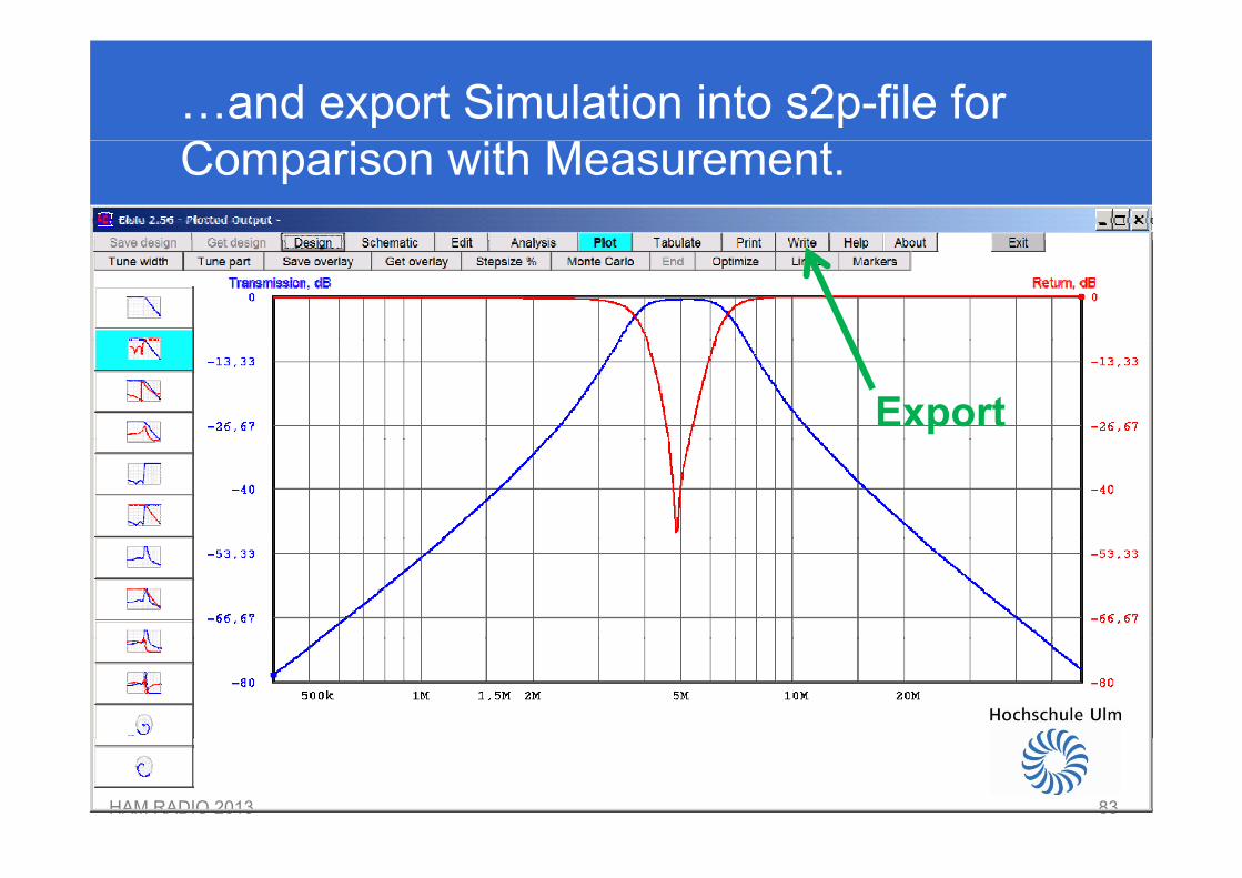
…and export Simulation into s2p-file forComparison with Measurement.
Export
HAM RADIO 2013 8383
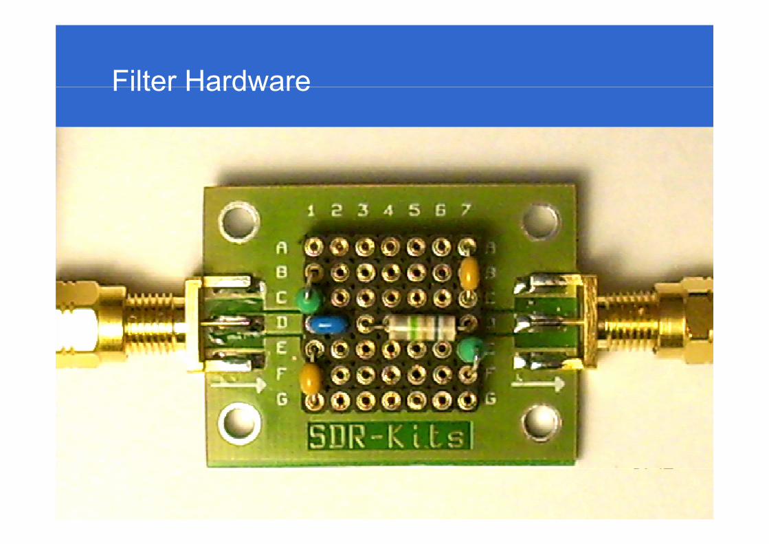
Filter HardwareFilter Hardware
HAM RADIO 2013 8484
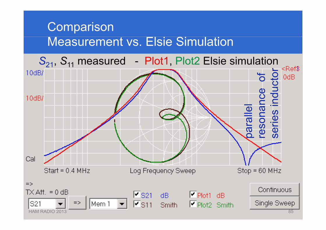
ComparisonMeasurement vs. Elsie Simulation
S21 S11 measured - Plot1 Plot2 Elsie simulation
eof
ucto
rS21, S11 measured Plot1, Plot2 Elsie simulation
lel
nanc
es
indu
para
lre
son
serie
HAM RADIO 2013 8585
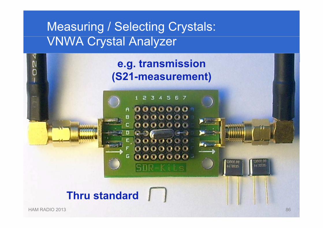
Measuring / Selecting Crystals:VNWA Crystal Analyzer
e g transmissione.g. transmission(S21-measurement)
Th t d dHAM RADIO 2013 86
Thru standard86
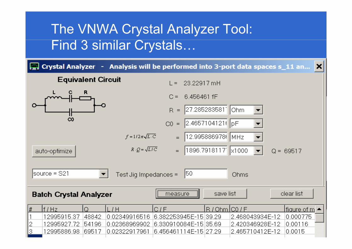
The VNWA Crystal Analyzer Tool:Find 3 similar Crystals…
HAM RADIO 2013 8787
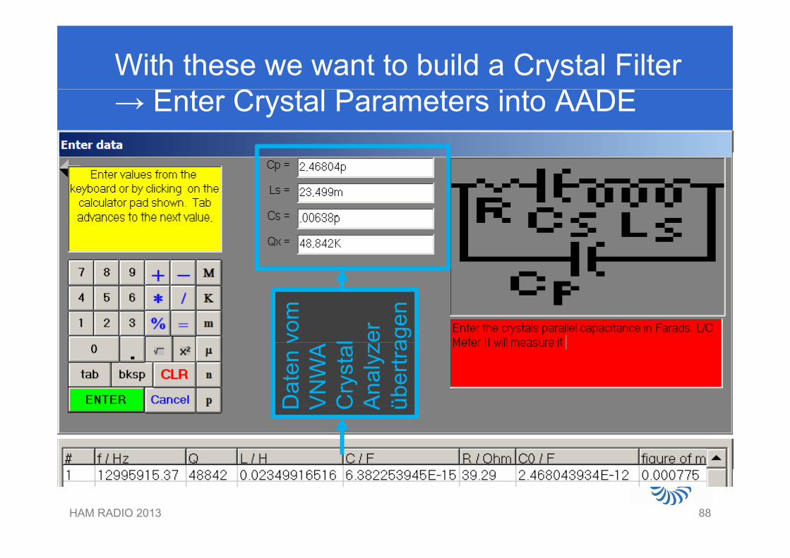
With these we want to build a Crystal Filter→ Enter Crystal Parameters into AADE
vom
l er
agen
Dat
en v
VN
WA
Cry
stal
Ana
lyz
über
tra
D V C A ü
HAM RADIO 2013 8888
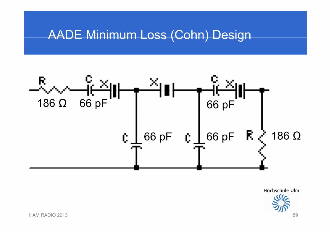
AADE Minimum Loss (Cohn) DesignAADE Minimum Loss (Cohn) Design
186 Ω 66 pF 66 pF
186 Ω66 pF 66 pF
HAM RADIO 2013 8989
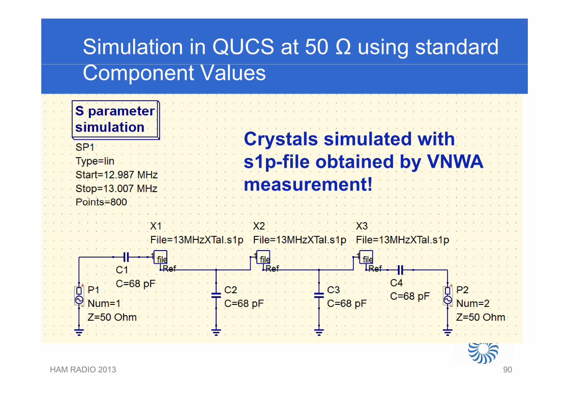
Simulation in QUCS at 50 Ω using standardComponent Values
Crystals simulated with1 fil bt i d b VNWAs1p-file obtained by VNWA
measurement!
HAM RADIO 2013 9090
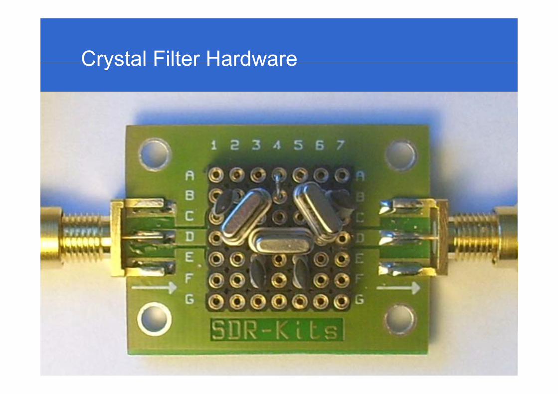
Crystal Filter HardwareCrystal Filter Hardware
HAM RADIO 2013 9191
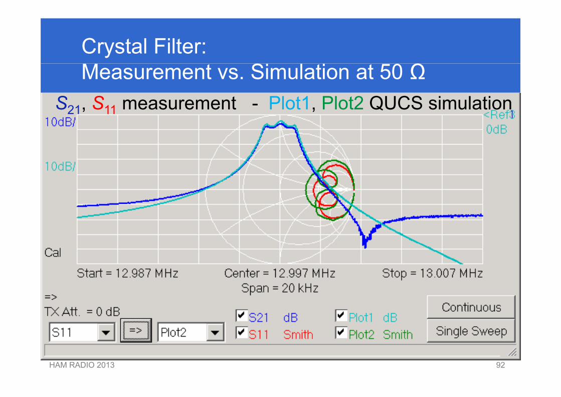
Crystal Filter: Measurement vs. Simulation at 50 Ω
S21, S11 measurement - Plot1, Plot2 QUCS simulationS21, S11 measurement Plot1, Plot2 QUCS simulation
HAM RADIO 2013 9292
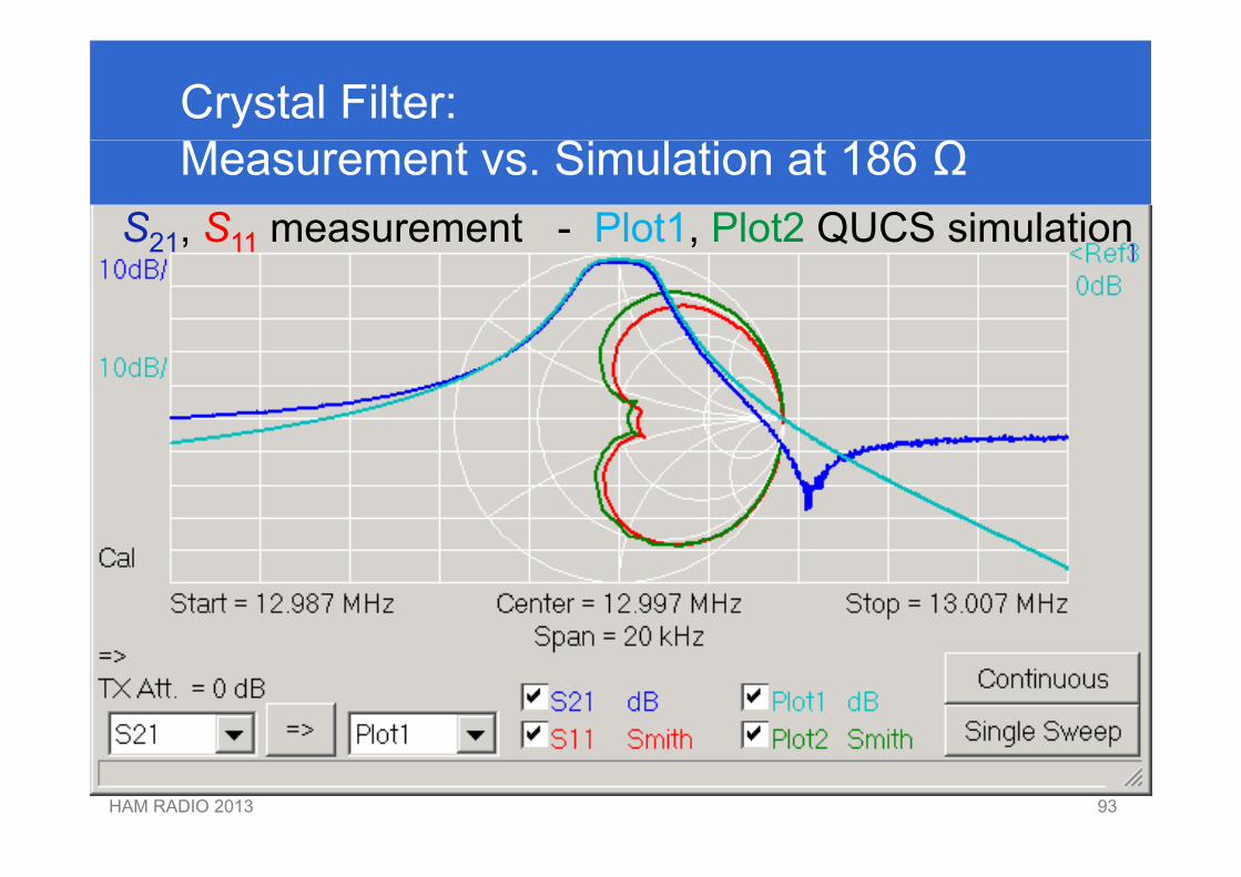
Crystal Filter: Measurement vs. Simulation at 186 Ω
S21, S11 measurement - Plot1, Plot2 QUCS simulationS21, S11 measurement Plot1, Plot2 QUCS simulation
HAM RADIO 2013 9393
Now we are able toNow, we are able to…
• Measure components• Measure components• Design filtersg• Simulate filters• Measure filters
Have fun at the workshop!HAM RADIO 2013 94
Have fun at the workshop!
94

Many thanks for your attention!Many thanks for your attention!
HAM RADIO 2013 9595