hamlet swing & fixed specification section 00 00 00
TRANSCRIPT

Hamlet Swing & Fixed SPECIFICATION Section 00 00 00
Bridges Replacement TITLE SHEET Page 1
R.073593.001 2018-07-20
PROJECT TITLE Hamlet, Ontario
Trent-Severn Waterway
Hamlet Swing & Fixed Bridges
(Bridge 57 & 58) Replacement
Historic Site of Canada
Parks Canada Agency
PROJECT NUMBER R.073593.001
PROJECT DATE 2018-07-20

Hamlet Swing & Fixed SEALS PAGE Section 00 01 07 Bridges Replacement R.073593.001 2018-07-20 Structural Engineer: Roadway Engineer:
____ ____ Karen Liu Sam Dinatolo Mechanical Engineer: Electrical Engineer:
____ ____ Jeffrey Keyt Gareth Rees

Hamlet Swing & Fixed List of Contents Section 00 01 11
Bridges Replacement Page 1
R.073593.001 2018-07-20
Section Title Pages
Division 00 - Procurement and Contracting Requirements
00 00 00 SPECIFICATION TITLE SHEET 1
00 01 07 PROFESSIONAL SEALS PAGE 1
00 01 11 LIST OF CONTENTS 4
Division 01 - General Requirements
01 11 00 SUMMARY OF WORK 8
01 14 00 WORK RESTRICTIONS 4
01 15 00 ACCESS AND PROTECTION 4
01 15 01 DEWATERING 1
01 22 01 MEASUREMENT AND PAYMENT 4
01 29 83 PAYMENT PROCEDURES FOR TESTING LABORATORY SERVICES 2
01 31 19 PROJECT MEETINGS 3
01 32 16 CONSTRUCTION PROGRESS SCHEDULE - BAR (GANTT) CHART 5
01 33 00 SUBMITTAL PROCEDURES 6
01 35 29 HEALTH AND SAFETY REQUIREMENTS 6
01 35 43 ENVIRONMENTAL PROCEDURES 8
01 41 00 REGULATORY REQUIREMENTS 2
01 45 00 QUALITY CONTROL 7
01 52 00 CONSTRUCTION FACILITIES 8
01 54 00 ACCESS TO WORK AREAS 3
01 55 26 TRAFFIC CONTROL 5
01 56 00 TEMPORARY BARRIERS AND ENCLOSURES 2
01 61 00 COMMON PRODUCT REQUIREMENTS 6
01 71 00 EXAMINATION AND PREPARATION 4
01 74 11 CLEANING 2
01 74 21 CONSTRUCTION/DEMOLITION WASTE MANAGEMENT AND DISPOSAL 3
01 77 00 CLOSEOUT PROCEDURES 2
01 78 00 CLOSEOUT SUBMITTALS 7
01 79 00 DEMONSTRATION AND TRAINING 3
01 91 00 COMMISSIONING - GENERAL REQUIREMENTS 3
01 91 13 GENERAL COMMISSIONING (CX) REQUIREMENTS 13
01 91 20 PROJECT COMMISSIONING 6
01 91 33 COMMISSIONING FORMS 3
01 91 35 SWING BRIDGE BALANCING 6
Division 02 - Existing Conditions
02 41 13.14 PAVING REMOVAL 5
02 41 16.01 STRUCTURE DEMOLITION - SHORT FORM 3
02 42 13 DECONSTRUCTION OF STRUCTURES 12
02 81 01 HAZARDOUS MATERIALS 4
02 82 00.01 ASBESTOS ABATEMENT – MINIMUM PRECAUTIONS 7
Division 03 - Concrete
03 10 00 CONCRETE FORMING AND ACCESSORIES 3
03 20 00 CONCRETE REINFORCING 4
03 30 00.01 CAST-IN-PLACE CONCRETE 5
03 30 01 DOWELS 4

Hamlet Swing & Fixed List of Contents Section 00 01 11
Bridges Replacement Page 2
R.073593.001 2018-07-20
03 37 26 UNDERWATER PLACED CONCRETE 5
Division 05 - Metals
05 12 33 STRUCTURAL STEEL FOR BRIDGES 17
05 50 00 METAL FABRICATIONS 8
Division 06 - Wood, Plastics, and Composites
06 15 00 WOOD DECKING 4
Division 09 - Finishes
09 97 19 PAINTING EXTERIOR METAL SURFACES 14
09 97 20 METALIZING STRUCTURAL STEEL 8
Division 10 - Specialties
10 14 53 TRAFFIC SIGNAGE 7
Division 13 - Special Construction
13 34 23 PREFABRICATED BUILDINGS 9
Division 24 – Hydraulics
24 05 00 HYDRAULIC WORK – GENERAL 33
24 05 01 HPU WORK ELECTRICAL AND CONTROL PANELS 21
Division 26 - Electrical
26 05 00 COMMON WORK RESULTS FOR ELECTRICAL 36
26 05 21 WIRES AND CABLES (0-1000 V) 14
26 05 26 GROUNDING AND BONDING FOR ELECTRICAL SYSTEMS 11
26 05 29 HANGERS AND SUPPORTS FOR ELECTRICAL SYSTEMS 6
26 24 16 PANELBOARDS 10
26 24 22 FIELD INSTRUCTION DEVICES 6
26 27 26 WIRING DEVICES 6
26 28 23 SAFETY DISCONNECT SWITCHES 5
26 56 20 NAGIVATION LIGHTS 5
26 56 21.1 TRAFFIC GATES 7
26 56 22 TRAFFIC SIGNALS 4
26 60 13 LOW VOLTAGE MOTORS 14
Division 27 - Communications
27 51 23 PUBLIC ADDRESS SYSTEM 7
Division 28 - Electronic Safety and Security
28 23 00 VIDEO SURVEILLANCE 7

Hamlet Swing & Fixed List of Contents Section 00 01 11
Bridges Replacement Page 3
R.073593.001 2018-07-20
Division 29 – Mechanical
29 05 00 MECHANICAL WORK – GENERAL 24
Division 31 - Earthwork
31 05 16 AGGREGATE MATERIALS 3
31 11 00 CLEARING AND GRUBBING 3
31 22 13 ROUGH GRADING 2
31 23 33.01 EXCAVATING, TRENCHING AND BACKFILLING 4
31 24 13 ROADWAY EMBANKMENTS 7
31 25 05 EROSION AND SEDIMENT CONTROL 3
31 32 19.01 GEOTEXTILES 4
31 37 00 RIP-RAP 2
31 61 13 PILE FOUNDATIONS, GENERAL REQUIREMENTS 4
31 62 16.13 STEEL SHEET PILES 7
31 63 19 MICROPILES 19
Division 32 - Exterior Improvements
32 01 90.33 TREE AND SHRUB PRESERVATION 3
32 11 18 GRANULAR “A” 1
32 11 19 GRANULAR “B” TYPE II 1
32 11 23 AGGREGATE BASE COURSES 3
32 12 13.16 ASPHALT TACK COATS 5
32 12 16 ASPHALT PAVING 6
32 15 60 ROADWAY DUST CONTROL 1
32 17 23 PAVEMENT MARKINGS 3
32 91 19.13 TOPSOIL PLACEMENT AND GRADING 5
32 92 23 SODDING 4
Division 33 - Utilities
33 05 16 MAINTENANCE HOLES AND CATCH BASIN STRUCTURES 3
33 41 00 STORM UTILITY DRAINAGE PIPING 5
33 46 16 SUBDRAINAGE PIPING 6
Division 34 - Transportation
34 71 13.25 VEHICLE W-BEAM GUIDE RAIL 5
Division 35 – Turbidity Curtain
35 49 25 TURBIDITY CURTAIN (SILT CURTAIN) 5
Division 40 - Process Integration
40 20 00 BRIDGE CONTROL SEQUENCE OF OPERATION 3
40 25 00 PROGRAMMABLE LOGIC CONTROLLER 26
Appendices
AS-BUILT DRAWINGS
HAZARDOUS BUILDING MATERIALS ASSESSMENT 23
BASIC IMPACT ASSESSMENT REPORT 98
GEOTECHNICAL INVESTIGATION REPORT 98

Hamlet Swing & Fixed List of Contents Section 00 01 11
Bridges Replacement Page 4
R.073593.001 2018-07-20
UNDERWATER BRIDGE INSPECTION REPORT 57
HYDROLOGY AND HYDRAULIC STUDY MEMO 6

Hamlet Swing & Fixed SUMMARY OF WORK Section 01 11 00
Bridges Replacement Page 1
R.073593.001 2018-07-20
PART 1 - GENERAL
1.1 SECTION INCLUDES
.1 Title and Description of Work.
.2 Precedence.
.3 Related Sections.
.4 Work Covered by Contract Documents.
.5 Contract Method.
.6 Lump Sum Work.
.7 Cost Breakdown.
.8 Work by others.
.9 Future work.
.10 Work sequence.
.11 Contractor Use of Premises.
.12 Alterations to Existing Bridges and Buildings Utilities/Components.
.13 Documents Required.
.14 Road Occupancy Permit.
.15 Parks Canada Permit Requirement.
.16 Ontario Provincial Standard Specification.
.17 Electrical Services.
.18 Electrical and Control System.
.19 Minimum Standards.
.20 Protection.
.21 Verification of Site Dimension.
.22 Regulatory Requirements.
.23 Licence Requirements.
.24 Permits/Authorities.
.25 Signs.
.26 Additional Drawings.
1.2 PRECEDENCE
.1 For Federal Government projects, Division 01 Sections take precedence over
technical specification sections in other Divisions of this Project Manual.
1.3 RELATED SECTIONS
.1 Not Used.
1.4 WORK COVERED BY CONTRACT DOCUMENTS
.1 Work of this Contract comprises structural, mechanical, hydraulic,
electrical, and road work for the replacement of the Hamlet Swing and Fixed
Bridges, located in Hamlet, Ontario. The work of the bridge replacement
includes all measures to deliver reliably operating swing and fixed bridges,
which also includes the necessary adjustments to refine its operation,
as indicated in the Contract Documents and/or Sections.
1.5 CONTRACT METHOD
.1 Construct Work under combined price contract.

Hamlet Swing & Fixed SUMMARY OF WORK Section 01 11 00
Bridges Replacement Page 2
R.073593.001 2018-07-20
1.6 LUMP SUM WORK
.1 Any work which is not included in the Unit Price Table is deemed to be included
in the lump sum price.
1.7 COST BREAKDOWN
.1 Within 48 hours of notification of acceptance of bid furnish a cost breakdown
by Section aggregating contract price.
.1 Submit cost breakdown prices for the lump sum work.
.2 Within 48 hours of acceptance of bid submit a list of Subcontractors and
Specialty Engineers. The list shall include all Subcontractors and Specialty
Engineers listed on the Qualification Forms as well as any other
subcontractors.
1.8 WORK BY OTHERS
.1 Co-operate with other Contractors in carrying out their respective works
and carry out instructions from Departmental Representative.
.2 Co-ordinate work with that of other Contractors. If any part of work under
this Contract depends for its proper execution or result upon work of another
Contractor, report promptly to Departmental Representative, in writing,
any defects which may interfere with proper execution of Work.
.3 Coordinate with the affected and involved utilities as part of the demolition
of the existing bridge hydraulic and electrical operating systems building.
.4 Coordinate with Hydro One.
1.9 FUTURE WORK
.1 Not used.
1.10 WORK SEQUENCE
.1 Comply with operational constraints, milestones, and completion dates. Work
must be monitored and completed to meet the goals at the milestones and
at the completion date.
.2 Complete the work as indicated in the Contract Documents and maintain
navigation traffic at all times during construction at the Hamlet Swing
and Fixed Bridges project site except as permitted in the Contract Documents.
.3 Milestone dates for work under this Contract are as follows:
.1 Work affecting navigation shall not occur until October 8, 2018.
.2 In-water work shall not occur between March 15, 2019 and May 31, 2019.
.3 Commissioning of the bridge shall be complete, and the bridge shall
be re-opened to navigation and two-way vehicle traffic by June 24, 2019.
.4 All work under this Contract must be completed by July 26, 2019.
Hamlet Swing & Fixed SUMMARY OF WORK Section 01 11 00
Bridges Replacement Page 3
R.073593.001 2018-07-20
.4 Required stages:
.1 Project award.
.2 Prepare and submit project schedule showing critical path.
.3 Obtain necessary permits.
.1 Permit to take and discharge water.
.2 Permit for submarine cables installation in water.
.4 Contractor mobilization, install environmental control measures.
.5 Initiate and maintain shop drawing submittal and review process.
.6 Implement and maintain Traffic Control Plan.
.7 Prepare, submit and implement construction staging plan once
approved.
.8 Implement environmental protocol measures.
.9 Clear and level temporary staging area.
.10 Divert traffic onto adjacent route as indicated in Roadway Drawings.
.11 Remove existing mechanical, hydraulic, and electrical equipment and
salvage equipment identified by Departmental Representative.
.12 Demolish and decommission existing electrical control house.
.13 Demolish existing superstructure.
.13 Regrade approaches to proposed profile.
.14 Maintain navigation clearance in navigation channel at all time during
navigational season.
.15 Install cofferdam.
.16 Install micropiles and rock anchors (if applicable).
.17 Construct footings.
.18 Construct abutments and ballast walls.
.19 Construct new control house and extend 600V service to the new
building. .20 Commence mechanical and electrical equipment installation.
.21 Construct/erect superstructure.
.22 Complete mechanical, hydraulic and electrical equipment
installation.
.23 Submit commissioning plan.
.24 Construct approach slabs.
.25 Install steel beam guiderails, warning gates and navigational
lighting at pivot pier and rest piers.
.26 Commission new structure.
.27 All disturbed soils within the construction limit will be restored
to grade with top soil, and provide surface treatment with sod.
.28 Regrade embankments.
.29 Open bridge to traffic.
.30 Demobilize, remove environmental control measures.
.5 Upon substantial completion of the project, and completion of commissioning,
provide operation and maintenance manuals (O&M) to the Departmental
Representative.
.6 Construct Work in stages to provide for continuous public usage.
.7 Maintain access to Parks Canada facilities at all times.
1.11 CONTRACTOR USE OF PREMISES
.1 Contractor has unrestricted use of site until Substantial Performance.
Hamlet Swing & Fixed SUMMARY OF WORK Section 01 11 00
Bridges Replacement Page 4
R.073593.001 2018-07-20
Exceptions are:
.1 The Contractor shall permit passage of boat/vessel traffic and
maintain the navigational opening shown on the Contract Drawings during
the navigational season. The winter shut down for the navigational opening
of the Severn River will be from October 8, 2018 to May 20, 2019
(Non-navigation season).
.2 Contractor shall limit use of premises for Work, for storage, and for access,
to allow;
.1 Owner occupancy.
.2 Public usage of the bridges (vehicular and pedestrian) prior to
demolishing of Hamlet Bridges and after commissioning of the new swing bridge
and the construction of the new fixed bridge.
.3 Permit passage of boat/vessel traffic during the navigational season.
.3 Coordinate use of premises under direction of Departmental Representative.
.4 Obtain and pay for use of additional off-site storage or work areas as needed
for operations under this Contract due to limited staging area in the
vicinity of the bridge site. Provide storage areas off site. Obtain
Provincial permit for sites not on federal land. No additional compensation
will be permitted. The cost associated for storage areas is deemed to be
included in the Contractor’s overall bid price as part of the Lump Sum items.
.5 Remove or alter existing work to prevent injury or damage to portions of
existing work which remain.
.6 Repair or replace portions of existing work which have been altered during
construction operations to match existing or adjoining work as directed
by Departmental Representative.
.7 At completion of operations the condition of existing work shall be equal
to, or better than, that which existing before new work started.
.8 The Contractor shall not permit any tools, equipment, vehicles, temporary
structures or parts thereof used or maintained for the purpose of building
or placing a work in or over the navigable water to remain in such water
beyond March 15, 2019.
.9 Where a work or a portion of the work that is being constructed or maintained
in navigable water causes debris or other material to accumulate on the
bed or surface of such water, the Contractor shall immediately remove the
debris or other material to the satisfaction of the Departmental
Representative.
.10 All in-water work shall be completed prior to March 14, 2019. This includes
complete removal of any temporary in-water works.
1.12 ALTERATIONS TO EXISTING BRIDGES AND BUILDING UTILITIES/COMPONENTS
.1 Remove and re-instate the following existing items.
.1 Water treatment system.

Hamlet Swing & Fixed SUMMARY OF WORK Section 01 11 00
Bridges Replacement Page 5
R.073593.001 2018-07-20
.2 Remove in good order, turn over to Department, and store within building
where designated by Departmental Representative:
.1 Mechanical and electrical items as indicated.
.3 Remove, temporarily store, clean, alter to suit and reinstall:
.1 Water, rain and flow gauges at the North Rest Pier.
.2 Railings at the Rest Pier.
.3 Signs on the bridges, approaches and the piers.
1.13 DOCUMENTS REQUIRED
.1 Maintain at job site, one paper copy of each document as follows:
.1 Contract Drawings.
.2 Specifications.
.3 Addenda and amendments.
.4 Reviewed Shop Drawings.
.5 List of Outstanding Shop Drawings.
.6 Change Orders.
.7 Other Modifications to Contract.
.8 Field Test Reports.
.9 Copy of Approved Work Schedule.
.10 Health and Safety Plan and Other Safety Related Documents.
.11 Environmental Management Plan (EMP).
.12 Other documents as specified.
.2 Owner Take-Over
.1 Schedule and substantially complete work prior to request of
Certificate of Substantial Completion and Final Certificate of
Completion. Issuance of both certificates to be coordinated with
commissioning as outlined in Section 01 91 13 – General Commissioning
(CX) Requirements.
1.14 ROAD OCCUPANCY PERMIT
.1 The Contractor shall obtain permits from adjacent townships (Orillia,
Severn, Gravenhurst) or Parks Canada Agency (PCA), as required, for use
and occupancy of roads at end near the bridge site as required to complete
the work under this contract.
1.15 PARKS CANADA PERMIT REQUIREMENTS
.1 As per the Historic Canal Regulations applicable to lands administered by
the Trent-Severn Waterway National Historic Site of Canada, a permit signed
by Parks Canada’s Ontario Waterways Director will be required to authorize
the project prior to commencement of project activities.
.2 Release of permit requires an accepted Environmental Management Plan (EMP)
and Health and Safety Plan by the Departmental Representative and Parks
Canada Agency (PCA).
.3 The contractor should provide EMP for PCA to issue a heritage Canal Permit
Hamlet Swing & Fixed SUMMARY OF WORK Section 01 11 00
Bridges Replacement Page 6
R.073593.001 2018-07-20
in order to do in-water work including Submarine Cable Installation.
1.16 ONTARIO PROVINCIAL STANDARD SPECIFICATION
.1 Where reference is made to an Ontario Provincial Standard Specification
(OPSS), the following shall apply: Remove and replace the term “Contract
Administrator: with “Departmental Representative” in the referenced OPSS
specification.
1.17 ELECTRICAL SERVICES
.1 Notify, Departmental Representative and coordinate with utility companies
of intended interruption of services and assist the Departmental
Representative in obtaining required permission and necessary permits.
.2 Contractor to coordinate with and pay Hydro One for the switch of the new
service. Contractor will subsequently get reimbursed at cost.
.3 Establish location and extent of service lines in area of work before
starting Work. Notify Departmental Representative of findings.
.4 Submit schedule to and obtain approval from Departmental Representative
for any shut-down or closure of active service or facility including power
and communications services. Adhere to approved schedule and provide notice
to affected parties.
.5 Where unknown services are encountered, immediately advise Departmental
Representative and confirm findings in writing.
.6 Protect, relocate or maintain existing active services. When inactive
services are encountered, cap off in manner approved by authorities having
jurisdiction.
.7 Record locations of maintained, re-routed and abandoned service lines.
.8 Construct barriers in accordance with Section 01 56 00 - Temporary Barriers
and Enclosures.
1.18 ELECTRICAL AND CONTROL SYSTEM
.1 The scope of work includes furnishing, receiving, storing, installing,
commissioning and placing in service the all electrical and control system
as described in the project specification and design drawings.
.2 Electrical components, equipment and system shall satisfactorily pass all
applicable factory and field tests in accordance with project specification
requirements.
1.19 MINIMUM STANDARDS
.1 Materials are to be new and Work is to conform to the minimum applicable
standards of the latest versions of the Canadian Highway Bridge Design Code
(CAN/CSA S6), the National Building Code of Canada (where applicable), the

Hamlet Swing & Fixed SUMMARY OF WORK Section 01 11 00
Bridges Replacement Page 7
R.073593.001 2018-07-20
Canadian General Standards Board, the Canadian Standards Association, and
all applicable Provincial and Municipal codes. In the case of conflict or
discrepancy, the most stringent requirement is to apply.
1.20 PROTECTION
.1 Protect finished work against damage until takeover.
.2 Protect adjacent work against the spread of dust and dirt beyond the work
areas.
.3 Protect operatives and other users of site from all hazards.
.4 Other considerations include:
.1 Noise constraints per noise by-laws in nearby townships.
.2 Vibration limitation.
.3 Respect tourism and nearby resort and landowners.
.4 Monitor and protect against upstream flooding during and after
installation of cofferdams.
1.21 VERIFICATION OF SITE DIMENSION
.1 The Contractor is advised that all elevations and dimensions shown on the
plans are approximate only. Verify all existing dimensions and grades before
preparing and submitting shop drawings and before planning and undertaking
any construction work. Immediately report all discrepancies, in writing,
to the Departmental Representative.
1.22 REGULATORY REQUIREMENTS
.1 Compliance: Be fully acquainted with all rules, regulations and other
by-laws of the appropriate Provincial and Municipal governments relating
to the work of this Contract and comply with same.
.2 Comply with the regulations of the Province of Ontario with regards to every
aspect of the project.
.3 Fee permits, certificates: Pay all fees and obtain all permits. Provide
authorities with plans and information for acceptance certificates. Provide
inspection certificates as evidence that work conforms to requirements of
Authority having jurisdiction.
.4 Ensure compliance of employees with safety requirements of Contract
Documents, site specific health and safety plan(s), and all applicable
regulatory requirements.
1.23 LICENCE REQUIREMENTS
.1 The Contractor must be licensed to work in the Province of Ontario in
accordance with all provincial laws, regulations and requirements.
1.24 PERMITS/AUTHORITIES

Hamlet Swing & Fixed SUMMARY OF WORK Section 01 11 00
Bridges Replacement Page 8
R.073593.001 2018-07-20
.1 The Contractor shall obtain, and pay for, permits from authorities as
required for all operations and construction. He shall also comply with
all pertinent regulations of all authorities having jurisdiction over the
work. The Contractor shall provide copies of all permits to the Owner prior
to starting the work.
.2 The Contractor shall be responsible for obtaining all applicable permits,
inspections and approvals required and shall pay all charges in connection
there with.
1.25 SIGNS
.1 Provide common-use signs related to traffic control, information,
instruction, use of equipment, public safety devices, etc., in both English
and French languages or by the use of commonly understood graphic symbols
to the Departmental Representative’s approval.
.2 No advertising will be permitted on this project.
1.26 ADDITIONAL DRAWINGS
.1 Departmental Representative may furnish additional drawings for
clarification. These additional drawings have the same meaning and intent
as if they were included with plans referred to in Contract Documents.
PART 2 - PRODUCTS
2.1 NOT USED
.1 Not used.
PART 3 - EXECUTION
3.1 NOT USED
.1 Not used.
END OF SECTION

Hamlet Swing & Fixed WORK RESTRICTIONS Section 01 14 00
Bridges Replacement Page 1
R.073593.001 2018-07-20
PART 1 - GENERAL
1.1 ACCESS AND EGRESS
.1 Design, construct and maintain temporary "access to" and "egress from" work
areas, including stairs, runways, ramps or ladders and scaffolding,
independent of finished surfaces and in accordance with relevant municipal,
provincial and other regulations.
1.2 USE OF SITE AND FACILITIES
.1 Execute work with least possible interference or disturbance to normal use
of premises. Make arrangements with Departmental Representative to
facilitate work as stated.
.2 Where security is reduced by work provide temporary means to maintain
security.
.3 Departmental Representative will assign sanitary facilities for use by
Contractor's personnel. Keep facilities clean.
.4 Closures: protect work temporarily until permanent enclosures are
completed.
1.3 ALTERATIONS, ADDITIONS OR REPAIRS TO EXISTING BUILDING
.1 Execute work with least possible interference or disturbance public and
normal use of premises. Arrange with Departmental Representative to
facilitate execution of work.
1.4 EXISTING SERVICES
.1 Notify Departmental Representative utility companies of intended
interruption of services and obtain required permission.
.2 Where Work involves breaking into or connecting to existing services, give
Departmental Representative 48 hours of notice for necessary interruption
of mechanical or electrical service throughout course of work. Keep duration
of interruptions minimum. Carry out interruptions after normal working hours
of occupants, preferably on weekends.
.3 Construct barriers in accordance with Section 01 56 00.
.4 Prior to commencement of Work, arrange to locate underground utilities and
service connections that may be affected by the Work.
.5 Where unknown services are encountered, immediately advise Departmental
Representative and confirm findings in writing.
.6 Repair existing services damaged during construction as directed by
Departmental Representative and relevant utility authority at no additional
cost for this contract.

Hamlet Swing & Fixed WORK RESTRICTIONS Section 01 14 00
Bridges Replacement Page 2
R.073593.001 2018-07-20
.7 Record locations of maintained, re-routed, and abandoned services.
.8 There is an existing buried and submarine cable at the site providing power
and controls to the bridge. This must be maintained during the period after
award of the contract to the start of the non-navigation season, or until
operation of the bridge is no longer required.
.9 Provide temporary services when directed by Departmental Representative
to maintain critical systems.
.10 Protect, relocate, or maintain existing active services. When inactive
services are encountered, cap off in manner approved by authorities having
jurisdiction.
1.5 SPECIAL REQUIREMENTS
.1 The Contractor shall obtain road occupancy permits from the road
authorities for work under this Contract.
.2 Carry out noise generating Work in accordance with the noise by-law in the
adjacent townships.
.3 Submit schedule in accordance with Section 01 32 16.
.4 Ensure Contractor's personnel employed on site become familiar with and
obey regulations including safety, fire, traffic and security regulations.
.5 Keep within limits of work and avenues of ingress and egress.
.6 Prior to cutting or drilling horizontal or vertical surfaces including
concrete, concrete block or other structural substrate, determine location
of reinforcing, service lines, pipes, conduits or other items by x-ray,
ground penetrating radar or other appropriate method. Submit findings to
Departmental Representative prior to cutting or drilling.
1.6 SECURITY
.1 Where security has been reduced by Work of Contract, provide temporary means
to maintain security.
.2 Security clearances:
.1 Personnel employed on this project will be subject to security check.
Obtain clearance, as instructed, for each individual who will require to
enter premises.
.2 Personnel will be checked daily at start of work shift and provided
with pass which must be worn at all times. Pass must be returned at end
of work shift and personnel checked out.
.3 Contractor's personnel will require satisfactory RCMP initiated
security screening in order to complete Work in premises and on site.
.3 Security escort:

Hamlet Swing & Fixed WORK RESTRICTIONS Section 01 14 00
Bridges Replacement Page 3
R.073593.001 2018-07-20
.1 Personnel employed on this project must be escorted when executing
work in non-public areas during normal working hours. Personnel must be
escorted in all areas after normal working hours.
.2 Submit an escort request to Departmental Representative at least 14
days before service is needed. For requests submitted within time noted
above, costs of security escort will be paid for by Departmental
Representative. Cost incurred by late request will be Contractor's
responsibility.
.3 Any escort request may be cancelled free of charge if notification
of cancellation is given at least 4 hours before scheduled time of escort.
Cost incurred by late request will be Contractor's responsibility.
.4 Calculation of costs will be based on average hourly rate of security
officer for minimum of [8] hours per day for late service request and of
4 hours for late cancellations.
1.7 ROAD CLOSURES
.1 The bridge will be closed to traffic on August 28, 2018.
.2 The bridge will be re-open to traffic on May 22, 2019.
.3 During construction Route 49 (South Sparrow Lake Road, Canning Road), Route
13 (Southwood Road) and Route 11 (Hwy 11) will be used as detour.
.4 Detour details are included in the Traffic Management Plan in the Tender
Documents.
1.8 TRAFFIC CONTROL
.1 The Contractor shall provide all traffic control required to complete
the work. Traffic Control shall be in accordance with Ontario Traffic
Manual (OTM) Book 7.
1.9 SCHEDULING OF WORK
.1 Navigation shall not be impeded during the navigational season. The
navigation season is May 18, 2018 to October 8, 2018.
1.10 MEASUREMENT AND PAYMENT
.1 There shall be no measurement for this work.
.2 Payment will be under the Contract Lump Sum Amount and such payment shall
be full compensation of all design, labour, equipment, and materials
necessary to complete the work.
1.11 PRE-CONDITION AND POST-CONDITION SURVEY
.1 The Contractor shall undertake a pre-construction and post-construction
survey of the following:
.1 Trent-Severn waterway.

Hamlet Swing & Fixed WORK RESTRICTIONS Section 01 14 00
Bridges Replacement Page 4
R.073593.001 2018-07-20
.2 Muskoka District road 49, Canning road (CR49) and Hartley Road (for
150 m beyond the limits of construction west and east of the site).
.3 Water intakes within immediate vicinity (within 150 meters of the
limits of construction along the river).
.3 All buildings within 150 m of the limit of construction, or as agreed
to with the Departmental Representative.
.4 The survey shall be undertaken by a firm experienced in this type
of inspection. The reports shall be signed and stamped by a Professional
Engineer licensed in the Province of Ontario.
.5 The preconstruction survey (complete with notes, photographs, and
video) is to be submitted prior to mobilization on site.
.6 The post construction survey shall be submitted at the time of
completion of all work.
PART 2 - PRODUCTS
2.1 NOT USED
.1 Not Used.
PART 3 - EXECUTION
3.1 NOT USED
.1 Not Used.
END OF SECTION

Hamlet Swing & Fixed Access and Protection Section 01 15 00
Bridges Replacement Page 1
R.073593.001 2018-07-20
PART 1 - GENERAL
1.1 GENERAL
.1 The provisions of OPSS.MUNI 539 shall apply to this item except as amended
or extended herein or in other Sections. Remove and replace the term
“Contract Administrator” with “Departmental Representative” in the above
referenced OPSS specification.
.2 The Contractor shall be responsible for making arrangements for land use
beyond the boundaries of PCA-owned land. The Contractor shall also be
responsible for abiding by all rules and legislation associated with the
use of non-federal lands, including but not limited to, the acquisition
of necessary permits, as applicable.
1.2 OUTLINE OF WORK
.1 Provide safe and adequate access, scaffolding, work platforms, containment
systems and staging, on and around the structure to do all the Work indicated
in the Contract Documents. The Contractor shall:
.1 Ensure a safe working environment.
.2 Facilitate progress of Work in an efficient manner.
.3 Prevent debris from falling to the waterway below during both
demolition and construction.
.4 Protect areas or features adjacent to the Work during procedures.
.5 Protect Work and products against dampness and cold.
.6 Provide ambient temperatures and humidity levels for storage,
application, installation and curing of materials, or for welding.
.7 Allow inspection of the work and provide boat access (including a
boat operator and all necessary safety equipment) if required by the
Departmental Representative for such inspections at the Contractor’s
expense.
.2 The work involves both works on and off site. The work must be completed
in environmental conditions that allow maximum quality of work and
protection for the natural environment.
.3 All access shall conform with the most current Laws, Regulations, or Statutes
that apply to this type of work.
.4 The requirements of this section apply to all other sections of the
specification to provide an appropriate environment to complete the work
as required to achieve the best quality of the finished product.
.5 Be responsible for all re-grading of existing roads, pathways, trails,
entrances, fencing, guard rails, landscaping and access routes to suit
the Contractor’s purposes for site access. The Contractor shall also be
responsible for the restoration of all existing roads, pathways, trails,
entrances, fencing, guard rails and landscaping, including sodding of
disturbed areas, to pre-construction conditions or better. Any damage to
trees, sod, or any other property caused by the Contractor’s site access

Hamlet Swing & Fixed Access and Protection Section 01 15 00
Bridges Replacement Page 2
R.073593.001 2018-07-20
shall be corrected to the Departmental Representative’s satisfaction at
the Contractor’s expense.
.6 Design, construct, maintain, and remove temporary "access to" and "egress
from" work areas including, but not limited to, barges, temporary work
bridges, stairs, runways, ramps, ladders, scaffolding, containment systems
and staging, work platforms independent of finished surfaces.
.7 Provide safe and adequate access to the Departmental Representative for
inspection and measurement of all areas of the substructure and
superstructure.
.8 Prevent all debris, cutwater, or other deleterious material from falling,
flowing or otherwise finding its way into nearby waterways and roadways.
.9 Protect the surrounding environment and properties, the public, vehicular
and pedestrian traffic in a manner acceptable to the Departmental
Representative’s satisfaction at each stage of the work.
.10 Supply and apply water and/or dust suppressants for dust control when
directed by the Departmental Representative.
.11 Safely remove and dispose of all staging, access, containment and protection
systems, scaffolds and platforms upon completion of the work.
.12 Typical locations and areas of work are shown directly or implied through
reference or detail to associated working areas on the drawings. The
Contractor shall provide access and protection to carry out work in these
areas.
.13 Maintain access to all commercial, institutional, and private entrances
at all times.
1.3 REFERENCES
.1 Ontario Provincial Standard Specifications
.1 OPSS.MUNI 539 November 2014 Construction Specification for Temporary
Protection
1.4 SITE BARRIERS
.1 Site barriers must be sufficient to protect public and exclude them from
the work area.
1.5 SCAFFOLDING & ACCESS
.1 Provide all barges, scaffolding, suspended platforms, ladders, access,
and lifting equipment to carry out the work. Field measure to ensure proper
fit. Transition area from the ladder(s) or structure to the scaffolding
shall be clear of obstructions and cross bracing so people and materials
can easily enter.
.2 Carry out all work in accordance with the Occupational Health and Safety

Hamlet Swing & Fixed Access and Protection Section 01 15 00
Bridges Replacement Page 3
R.073593.001 2018-07-20
Act and the Site-Specific Safety Plan. Make all changes required by Ministry
of Labour officials and address all concerns of the Departmental
Representative.
.3 Make regular inspections of scaffolding and work platforms as the work
progresses.
1.6 LIGHTING
.1 In all areas of work ensure sufficient and good lighting is provided to
complete and inspect the work.
.2 Especially during night time work or in dark areas, provide additional
lighting in work areas and to Public ways to compensate for the lack of
natural lighting.
.3 Provide for the use of the Departmental Representative additional work
lights for inspection.
1.7 CLIMATE CONTROL
.1 Provide heat and/or dehumidifying of site enclosures where required to
complete the work.
1.8 SUBMISSIONS
.1 Submit to the Departmental Representative for review, a detailed proposal
for carrying out removals and construction for each applicable work item
a minimum of one (1) week prior to the commencement of any removals. Those
proposals shall outline the removal and new construction techniques,
sequence of operations and shall detail and dimension the Contractor’s
proposed staging, temporary supports/shoring, access, protection, and
containment systems.
.2 Submissions for access platforms, barges, and work bridges shall bear the
seal and signature of a Professional Engineer licensed in the Province of
Ontario, who shall be responsible for the detailed design and subsequent
inspection of the access platforms/protection system as installed on site,
and shall certify in writing its compliance with the design requirements.
.3 Six (6) sets of working drawings and documents shall be submitted to the
Departmental Representative for review of access and protection schemes.
Work shall not proceed until the Departmental Representative has reviewed
the drawings and provided written authorization for the Contractor to
proceed with the work.
.4 The Departmental Representative’s approval shall not release the Contractor
from liability for any damage or any consequence as a result of inadequate
protection design.
1.9 MEASUREMENT AND PAYMENT
.1 There shall be no measurement for this work.

Hamlet Swing & Fixed Access and Protection Section 01 15 00
Bridges Replacement Page 4
R.073593.001 2018-07-20
.2 Payment will be under the Contract Lump Sum Amount and such payment shall
be full compensation of all design, labour, equipment and materials
necessary to complete the work.
PART 2 - PRODUCTS
2.1 GENERAL
.1 In accordance with OPSS.MUNI 539 except as amended or extended herein or
in other Sections. Remove and replace the term “Contract Administrator”
with “Departmental Representative” in the above referenced OPSS
specification.
2.2 MATERIALS
.1 The following alternatives are acceptable:
.1 New materials; or,
.2 Used, salvaged or recycled materials, in good condition, subject to
the approval of the Departmental Representative; or,
.3 Prefabricated, portable components in a good, safe condition,
approved by the Contractor’s design engineer as to type, materials and
detail.
PART 3 - EXECUTION
3.1 NOT USED
.1 Not used.
END OF SECTION

Hamlet Swing & Fixed DEWATERING Section 01 15 01 Bridges Replacement Page 1 R.073593.001 2018-07-20
PART 1 - GENERAL 1.1 GENERAL
.1 The provisions of OPSS 517 shall apply to this item except as amended or extended herein or in other Sections. Remove and replace the term “Contract Administrator” with “Departmental Representative” in the above referenced OPSS specification.
1.2 OUTLINE OF WORK
.1 Install cofferdam per contract documents, and dewater all excavations as required to complete the work under this Contract.
1.3 REFERENCES
.1 Ontario Provincial Standard Specifications .1 OPSS 517 November 2016 Construction Specification for Dewatering of Pipeline, Utility, and Associated Structure Excavation.
1.4 MEASUREMENT AND PAYMENT
.1 There shall be no measurement for this work. .2 Payment will be under the Contract Lump Sum Amount and such payment shall
be full compensation of all design, labour, equipment and materials necessary to complete the work.
PART 2 - PRODUCTS 2.1 GENERAL
.1 In accordance with OPSS 517 except as amended or extended herein or in other Sections. Remove and replace the term “Contract Administrator” with “Departmental Representative” in the above referenced OPSS specification.
PART 3 - EXECUTION 3.1 GENERAL
.1 Not used.
END OF SECTION

Hamlet Swing & Fixed Measurement and Payment Section 01 22 01
Bridges Replacement Page 1
R.073593.001 2018-07-20
PART 1 - GENERAL
1.1 MEASUREMENT AND PAYMENT PROCEDURES
.1 Lump Sum Price – For the work which is not designated in the Unit Price
Table there shall be no measurement and shall be deemed to be included as
part of the contract Lump Sum Price. This item includes all costs associated
to perform the work including but not limited to material, equipment,
personnel, and overhead. Items included in the Lump Sum Price are, but not
limited to, the following:
.1 Miscellaneous Site Work and General Requirements.
.2 Site Safety.
.3 Supply and installation of temporary erosion, shop drawings,
preparation of schedules, sedimentation control measures and dewatering
activities.
.4 Earth excavation for structure and backfill at the structure in
accordance with the drawings and specifications. The earth excavation and
backfill included in the Lump Sum Price is limited to the end of the frost
tapers shown on the Contract Drawings.
.5 Micropiles, tremie concrete, reinforcing steel, and testing.
.6 Supply and placement of concrete in abutments, wingwalls, approach
slabs, piers, rest piers, traffic gate footings, control console.
.7 Supply, Fabrication, Delivery and Erection of structural, mechanical
and hydraulic steel components including all temporary works, bearings,
supports and all anchorages. Balance plates are excluded from the Lump Sum
Price, and is considered unit.
.8 Design, construction, and maintenance of all temporary structures
(temporary support and foundations, shoring, bracing, working platforms,
scaffolding, stability bracing, cofferdams etc.) required to complete the
work.
.9 Supply and installation of rest pier SSP including all anchorages.
.10 Supply, Fabrication, Delivery and Erection of Railing, and all
anchorages.
.11 Coating of structural steel, railings, mechanical and hydraulic
components.
.12 Supply and installation of bridge timber deck and timber running
boards, including all deck components including flashing bolts anchors.
.13 Supply and installation of joint armouring angles and anchorages.
.14 Salvage and deliver to/store at the designated place per instruction
of Departmental Representative, the existing bridge hydraulic and
electrical system for re-use by owner.
.15 Removal and disposal of the existing bridge structure including all
the electrical, mechanical and hydraulic equipment to the limits shown on
the contract drawings.
.16 Removal of topsoil, wooden posts and steel cables, signs, asphalt
roadway and granular materials, and boulders.
.17 Supply and installation of traffic lights, warning, traffic signs
including all foundation work.
.18 Contractor to coordinate with and pay Hydro One for the new 600V
services. Contractor will subsequently get reimbursed at cost.
.19 Design, supply and installation of a control house with mechanical
and electrical room and storage facility including all connections to

Hamlet Swing & Fixed Measurement and Payment Section 01 22 01
Bridges Replacement Page 2
R.073593.001 2018-07-20
existing services.
.20 Design, supply and installation of concrete block retaining wall with
the finish per selection and instruction of Departmental Representative.
.21 Design, supply and installation of doors, windows, and frames in the
control house including all associated accessories, utilities and hardware.
Removal and restoration of the existing water system.
.22 Supply and installation of miscellaneous metals including ladders
and railings.
.23 Removal of the existing control house in its entirely including the
foundations, decommission of the mechanical and electrical room in the
basement including capping all utilities and removal and disposal of septic
tank.
.24 Remove and salvage bridge mechanical and electrical systems including
Operator control station, traffic gates, electrical components including
all hydraulic power units, cylinders and valves, balance wheels, end
castors, end lifts and locking pin assembly for the re-use by the owner.
.25 Supply and installation of all mechanical components including:
center bearing, span drive machinery, balance wheel and track, end support
castors, end lift/support machinery, hydraulic system live load rollers,
full open and closed stops. This item also includes balance calculations
and balance testing of the swing span as well as any adjustment required
to balance the bridge.
.26 Supply and installation, testing and commissioning of Hydraulic
Equipment including hydraulic piping and hoses including clips, fasteners,
cast in place concrete trench and cover.
.27 Supply and installation, testing and commissioning of electrical
components including: all electrical service and MCC, bridge PLC control
system, lighting and power for the new control house including the mechanical
and electrical room, electric power and control in-ground troughs,
handholes, junction boxes, conduits, hangers, etc. for the new electrical
and storage building and the new swing span.
.28 Commissioning.
.29 Training.
.30 Preparation of Operation and Maintenance Manuals (O&M).
.31 Clearing and grubbing.
.32 Traffic Control, temporary signs, and barricades for bridge closure.
.33 Roadway dust control.
.34 Construction Camera with the minimum interval of 10 minutes.
.35 CCTV.
.2 All work that is not specifically addressed and covered in the Unit Price
Item list but is indicated to be completed or required to be completed in
order to complete the work is to be deemed included in the Contract Lump
Sum.
.3 The following Item titles, units and their respective associated sections
list work included in each item. Further description of the work can be
found in the sections referenced.
.1 Items which are measured by the metre shall be measured along
centreline of installation unless otherwise indicated.
.2 Longitudinal and transverse measurement shall be made on the actual
flat or sloped surface.
.3 In computing volumes of excavation, average end area method will be

Hamlet Swing & Fixed Measurement and Payment Section 01 22 01
Bridges Replacement Page 3
R.073593.001 2018-07-20
used unless otherwise directed by Departmental Representative.
.4 All volume measurements refer to in-place measures unless specified
otherwise.
.5 Materials which are specified for measurement by mass shall be weighed
on scales approved by Departmental Representative. Units used to haul
material being paid for by mass shall bear legible identification numbers
plainly visible to scale person as it approaches and leaves scale-house.
.6 The numbers of the items described below correspond to the numbers
in the Unit Price Table.
.4 Item No. 1 – Common Excavation other than for bridge structure
.1 Item No. 2 shall be paid in cubic meters measured as actual volume
removed for road construction based on cross section as detailed in Section
31 23 33.01 – Excavating, Grading and Backfilling. This item excludes earth
excavation for structure which is included in the Lump Sum Price.
.5 Item No. 2 - Asphalt Type Hot Mix Asphalt HDBC
.1 Item No. 3 shall be paid in tonnes as determined by actual weigh slips
as detailed in Section 32 12 16.
.6 Item No. 3 - Asphalt Type Hot Mix Asphalt HL1
.1 Item No. 4 shall be paid in Tonnes as determined by actual weigh slips
as detailed in Section 32 12 16.
.7 Item No. 4 - Asphalt Tack Coat
.1 Item No 5 shall be paid in square meters as detailed in Section 32
12 13.16.
.8 Item No. 5 – Supply, place and compact Granular A
.1 Item No. 8 shall be paid in Tonnes (including supply placement and
compaction as determined by actual weigh slips. This item excludes
structural backfill which is included in the Lump Sum Price.
.9 Item No. 6 – Supply, place and compact Granular B Type II
.1 Item No. 9 shall be paid in Tonnes (including supply placement and
compaction as determined by actual weigh slips. This item excludes
structural backfill which is included in the Lump Sum Price.
.10 Item No. 7 - Top Soil Placement and Grading
.1 Item No. 13 shall be paid in cubic metres as measured on site as
detailed in Section 32 91 19.13.
.11 Item No 8 – Supply and place Sod
.1 Item No 15 shall be paid in square metres laid as detailed in Section
32 92 23.
.12 Item No. 9 – Supply and place Geotextiles
.1 Item No. 32 shall be paid in square metres as detailed in Section
31 32 19.01.
.13 Item No. 10 – Compaction of Subgrade
.1 Item No. 33 shall be paid in square metres as detailed in Section
31 23 33.01 and 31 22 13.

Hamlet Swing & Fixed Measurement and Payment Section 01 22 01
Bridges Replacement Page 4
R.073593.001 2018-07-20
PART 2 - PRODUCTS
2.1 NOT USED
.1 Not Used
PART 3 - EXECUTION
3.1 NOT USED
.1 Not used.
END OF SECTION
Hamlet Swing & Fixed PAYMENT PROCEDURES FOR Section 01 29 83 Bridges Replacement TESTING LABORATORY SERVICES Page 1 R.073593.001 2018-07-20
PART 1 - GENERAL 1.1 RELATED REQUIREMENTS
.1 Particular requirements for Quality Assurance inspection and testing to be carried out by testing laboratory designated by Departmental Representative.
1.2 APPOINTMENT AND PAYMENT
.1 Departmental Representative will appoint and pay for services of testing laboratory except follows: .1 Inspection and testing required by laws, ordinances, rules, regulations or orders of public authorities. .2 Inspection and testing performed exclusively for Contractor's convenience. .3 Testing, adjustment and balancing of conveying systems, mechanical and electrical equipment and systems. .4 Mill tests and certificates of compliance. .5 Tests specified to be carried out by Contractor under supervision of Departmental Representative. .6 Additional tests specified as follows:
.1 Concrete testing will be arranged and paid for by the Contractor using an independent CSA Certified Testing Company and field personnel. This includes all site tests of the plastic concrete during placement and all compression tests (including curing) and other tests performed on the hardened concrete. Representative samples from each concrete pour shall be taken and tested. The Departmental Representative may run parallel test at their discretion.
.2 Asphalt mix design and tests, field compaction tests, field sample collection, and testing of the asphalt.
.3 Mastic asphalt mix design and tests, field sample collection and testing of the asphalt.
.4 Concrete mix design development and laboratory testing as may be required to meet Contract requirements.
.5 All electrical inspections required by the authority having jurisdiction. .6 All other testing and inspections identified in the Contract Documents, where the Contractor is to arrange and pay for the inspection and tests (micropiles, metalizing, coating, galvanizing, metal fabrication and others). .7 Inspection and testing required by the Contractor as defined elsewhere in the Contract Documents.
.2 Where tests or inspections by designated testing laboratory reveal Work
not in accordance with contract requirements, pay costs for additional tests or inspections as required by Departmental Representative to verify acceptability of corrected work.
1.3 CONTRACTOR'S RESPONSIBILITIES
.1 Provide labour, equipment and facilities to aid the Departmental

Hamlet Swing & Fixed PAYMENT PROCEDURES FOR Section 01 29 83 Bridges Replacement TESTING LABORATORY SERVICES Page 2 R.073593.001 2018-07-20
Representative with any quality assurance testing and all inspections in the order of: .1 Provide access, including boat access if required, to Work for inspection and testing. .2 Facilitate inspections and tests. .3 Make good Work disturbed by inspection and test. .4 Provide storage on site for laboratory's exclusive use to store equipment and cure test samples.
.2 Notify Departmental Representative 48 hours minimum sufficiently in advance
of operations to allow for assignment of laboratory personnel and scheduling of test.
.3 Where materials are specified to be tested, deliver representative samples
in required quantity to testing laboratory.
.4 Pay costs for uncovering and making good Work that is covered before required inspection or testing is completed and approved by Departmental Representative.
PART 2 - PRODUCTS 2.1 NOT USED
.1 Not Used.
PART 3 - EXECUTION 3.1 NOT USED
.1 Not Used.
END OF SECTION

Hamlet Swing & Fixed PROJECT MEETINGS Section 01 31 19
Bridges Replacement Page 1
R.073593.001 2018-07-20
PART 1 - GENERAL
1.1 ADMINISTRATIVE
.1 Schedule and administer project meetings throughout the progress of the
work at the call of Departmental Representative.
.2 Prepare agenda for meetings.
.3 Distribute written notice of each meeting 4 days in advance of meeting date
to Departmental Representative.
.4 Provide physical space and make arrangements for meetings.
.5 Preside at meetings.
.6 Unless directed otherwise by Departmental Representative, record minutes
of meetings. Minutes shall be circulated to attending parties and affected
parties not in attendance within three (3) days after meeting.
.7 Representative of Contractor, Subcontractor and suppliers attending
meetings will be qualified and authorized to act on behalf of party each
represents.
1.2 PRECONSTRUCTION MEETING
.1 Within ten (10) days after award of Contract, request a meeting of parties
in contract to discuss and resolve administrative procedures and
responsibilities.
.2 Departmental Representative, Contractor, major Subcontractors, field
inspectors and supervisors are required to be in attendance.
.3 Establish time and location of meeting and notify parties concerned minimum
five (5) days before meeting.
.4 Incorporate mutually agreed variations to Contract Documents into
Agreement, prior to signing.
.5 Agenda to include:
.1 Appointment of official representative of participants in the Work.
.2 Schedule of Work: in accordance with Section 01 32 16.
.3 Schedule of submission of shop drawings, samples, mock-ups, colour
chips. Submit submittals in accordance with Section 01 33 00.
.4 Requirements for temporary facilities, site sign, offices, storage
sheds, utilities, fences in accordance with Section 01 52 00.
.5 Delivery schedule of specified equipment.
.6 Site security in accordance with Section 01 56 00.
.7 Health and safety in accordance with Section 01 35 29.
.8 Proposed changes, change orders, procedures, approvals required,
mark-up percentages permitted, time extensions, overtime, administrative
requirements.

Hamlet Swing & Fixed PROJECT MEETINGS Section 01 31 19
Bridges Replacement Page 2
R.073593.001 2018-07-20
.9 Owner provided products.
.10 Record drawings and specifications in accordance with Sections
01 33 00 and 01 78 00.
.11 Maintenance manuals in accordance with Section 01 78 00.
.12 Take-over procedures, acceptance, warranties in accordance with
Section 01 78 00.
.13 Monthly progress claims, administrative procedures, photographs,
hold backs.
.14 Appointment of inspection and testing agencies or firms.
.15 Insurances, transcript of policies.
1.3 PROGRESS MEETINGS
.1 During course of Work, schedule progress meetings Bi-weekly. Additional
meeting may be scheduled as required.
.2 Contractor, major Subcontractors involved in Work and Departmental
Representative are to be in attendance.
.3 Notify parties minimum seven (7) days prior to meetings.
.4 Record minutes of meetings and circulate to attending parties and affected
parties not in attendance within five (5) days after meeting.
.5 Departmental Representative will provide written notification of change
to meeting schedule established upon contract award twenty four (24) hours
prior to scheduled meeting.
.6 Agenda to include the following:
.1 Review, approval of minutes of previous meeting.
.2 Review of Work progress since previous meeting.
.3 Field observations, problems, conflicts.
.4 Problems which impede construction schedule.
.5 Review of off-site fabrication delivery schedules.
.6 Corrective measures and procedures to regain projected schedule.
.7 Revision to construction schedule.
.8 Progress schedule, during succeeding work period.
.9 Review submittal schedules: expedite as required.
.10 Maintenance of quality standards.
.11 Review proposed changes for effect on construction schedule and on
completion date.
.12 Other business.
.1 Progress on action items from previous meetings.
.2 Any complaints from residents in vicinity of construction/
demolition.
.3 Construction budget/cash flow review and update.
.4 Review of health and safety issues or concerns.
.5 Shop drawing status and reviews.
.6 Site instructions.
.7 Environmental issues.
PART 2 - PRODUCTS

Hamlet Swing & Fixed PROJECT MEETINGS Section 01 31 19
Bridges Replacement Page 3
R.073593.001 2018-07-20
2.1 NOT USED
.1 Not Used.
PART 3 - EXECUTION
3.1 NOT USED
.1 Not Used.
END OF SECTION

Hamlet Swing & Fixed CONSTRUCTION PROGRESS Section 01 32 16
Bridges Replacement SCHEDULE - BAR (GANTT) Page 1
R.073593.001 CHART 2018-07-20
PART 1 - GENERAL
1.1 DEFINITIONS
.1 Activity: element of Work performed during course of Project. Activity
normally has expected duration, and expected cost and expected resource
requirements. Activities can be subdivided into tasks.
.2 Bar Chart (GANTT Chart): graphic display of schedule-related information.
In typical bar chart, activities or other Project elements are listed down
left side of chart, dates are shown across top, and activity durations are
shown as date-placed horizontal bars. Generally Bar Chart should be derived
from commercially available computerized project management system.
.3 Baseline: original approved plan (for project, work package, or activity),
plus or minus approved scope changes.
.4 Construction Work Week: Monday to Friday, inclusive, will provide five day
work week and define schedule calendar working days as part of Bar (GANTT)
Chart submission.
.5 Duration: number of work periods (not including holidays or other nonworking
periods) required to complete activity or other project element. Usually
expressed as workdays or workweeks.
.6 Master Plan: summary-level schedule that identifies major activities and
key milestones.
.7 Milestone: significant event in project, usually completion of major
deliverable.
.8 Project Schedule: planned dates for performing activities and the planned
dates for meeting milestones. Dynamic, detailed record of tasks or
activities that must be accomplished to satisfy Project objectives.
Monitoring and control process involves using Project Schedule in executing
and controlling activities and is used as basis for decision making
throughout project life cycle.
.9 Project Planning, Monitoring and Control System: overall system operated
by Departmental Representative to enable monitoring of project work in
relation to established milestones.
1.2 REQUIREMENTS
.1 Ensure Master Plan and Detail Schedules are practical and remain within
specified Contract duration.
.2 Plan to complete Work in accordance with prescribed milestones and time
frame.
.3 Limit activity durations to maximum of approximately ten (10) working days,
to allow for progress reporting.

Hamlet Swing & Fixed CONSTRUCTION PROGRESS Section 01 32 16
Bridges Replacement SCHEDULE - BAR (GANTT) Page 2
R.073593.001 CHART 2018-07-20
.4 Ensure that it is understood that Award of Contract or time of beginning,
rate of progress, Certificate of Substantial Performance and Certificate
of Completion as defined times of completion are of essence of this contract.
.5 Refer to Section 01 14 00 for scheduling of work restrictions.
1.3 SUBMITTALS
.1 Provide submittals in accordance with Section 01 33 00.
.2 Submit to Departmental Representative within seven (7) working days of Award
of Contract Bar (GANTT) Chart as Master Plan for planning, monitoring and
reporting of project progress.
.3 Submit Project Schedule to Departmental Representative within seven (7)
working days of receipt of acceptance of Master Plan.
1.4 PROJECT MILESTONES
.1 Include mandatory project milestones for both Master Plan and Detailed
Schedule, but not be limited to, the following:
.1 Project award.
.2 Obtain necessary permits.
.3 Contractor mobilization.
.4 Implement and maintain traffic control plan.
.5 Relocate utility poles.
.6 Clear and level temporary staging area.
.7 Divert traffic onto the detour routes.
.8 Clear and level staging area.
.9 Install cofferdam.
.10 Remove existing mechanical, hydraulic, and electrical equipment.
.11 Demolish and decommission existing control house.
.12 Remove existing superstructure and substructure.
.13 Install micropiles.
.14 Construct footings.
.15 Construct abutments, excluding top of ballast walls, and east pier
without interference with existing structure during navigation season.
.16 Commence mechanical and electrical equipment installation including
electrical equipment and storage house.
.17 Erect steel superstructure.
.18 Construct necessary temporary works for superstructure.
.19 Install railings.
.20 Install timber deck, running boards and curbs.
.21 Commencement and completion of mechanical and electrical equipment
installation.
.22 Complete ballast wall.
.23 Commencement and completion of approach slabs, and joint
installation.
.24 Complete approaches.
.25 Paving.
.26 Pavement marking.
.27 Install steel beam guiderails.

Hamlet Swing & Fixed CONSTRUCTION PROGRESS Section 01 32 16
Bridges Replacement SCHEDULE - BAR (GANTT) Page 3
R.073593.001 CHART 2018-07-20
.28 Install new traffic signals, warning gate system.
.29 Commission new structure.
.30 Switch traffic to new bridges and decommission existing traffic
signals.
.31 Place top soil and sod.
.32 Complete landscaping.
.33 Demobilize.
1.5 MASTER PLAN
.1 Structure schedule to allow orderly planning, organizing and execution of
Work as Bar Chart (GANTT).
.2 Departmental Representative will review and return revised schedules within
five (5) working days.
.3 Revise impractical schedule and resubmit within five (5) working days.
.4 Accepted revised schedule will become Master Plan and be used as baseline
for updates.
1.6 PROJECT SCHEDULE
.1 Develop detailed Project Schedule derived from Master Plan.
.2 Ensure detailed Project Schedule includes as minimum milestone and activity
types as follows:
.1 Award.
.2 Shop Drawings, Samples.
.3 Permits.
.4 Mobilization.
.5 Excavation.
.6 Backfill.
.7 Building footings.
.8 Slab on grade.
.9 Structural Steel.
.10 Mechanical.
.11 Hydraulics.
.12 Electrical.
.13 Controls.
.14 Siding and Roofing.
.15 Interior Architecture (Walls, Floors and Ceiling).
.16 Plumbing.
.17 Lighting.
.18 Piping.
.19 Controls.
.20 Heating, Ventilating, and Air Conditioning.
.21 Millwork.
.22 Fire Systems.
.23 Testing and Commissioning.
.24 Supplied equipment long delivery items.
.25 Departmental Representative supplied equipment required dates.

Hamlet Swing & Fixed CONSTRUCTION PROGRESS Section 01 32 16
Bridges Replacement SCHEDULE - BAR (GANTT) Page 4
R.073593.001 CHART 2018-07-20
.3 The maintenance and adherence to the schedule is considered an integral
part of the work. Schedules must be realistic. If they are constantly not
met and/or if they are not updated and accepted by the Departmental
Representative and/or if additional effort is not applied to the project
to catch up to the schedule then up to 10% of the items will be deemed to
be incomplete work and never paid at the sole discretion of the Departmental
Representative. The actual completion time of the tasks shall be tracked
beside the schedule.
1.7 PROJECT SCHEDULE REPORTING
.1 Update Project Schedule on every two (2) weeks reflecting activity changes
and completions, as well as activities in progress. Provide the updated
schedule to the Departmental Representative a minimum of two (2) business
days prior to scheduled progress meetings.
.2 Include as part of Project Schedule, narrative report identifying Work
status to date, comparing current progress to baseline, presenting current
forecasts, defining problem areas, anticipated delays and impact with
possible mitigation.
.3 Contractor to provide and set up a construction camera to monitor progress
of the construction. A minimum time interval of 10 minutes is required.
1.8 PROJECT MEETINGS
.1 Discuss Project Schedule at regular site meetings specified in Section
01 31 19, identify activities that are behind schedule and provide measures
to regain slippage. Activities considered behind schedule are those with
projected start or completion dates later than current approved dates shown
on baseline schedule.
.2 Weather related delays with their remedial measures will be discussed. The
Contractor must anticipate normal to severe winter conditions. Only extreme
one in 50 year weather events will be considered for adjustments to schedule.
Weather records will be based on the nearest Environment Canada weather
monitoring station. The following table provides the water elevation and
occurrence of 50-year events.
Water
Elevation
(m)
50-year
Occurrence
213.50-213.74 10
> 213.50 24
213.75-213.99 10
> 213.75 14
> 214.00 4
.3 No progress payment will be made until the construction progress schedule
is approved and no subsequent payment will be made without an updated
schedule.
.4 Distribute copies of approved schedule to:
Hamlet Swing & Fixed CONSTRUCTION PROGRESS Section 01 32 16
Bridges Replacement SCHEDULE - BAR (GANTT) Page 5
R.073593.001 CHART 2018-07-20
.1 Job site office (must be hard copy).
.2 Sub-contractors.
.3 Other parties as directed.
.5 Instruct recipients to report to Contractor within five (5) days, any
problems anticipated by timetable shown in schedule.
PART 2 - PRODUCTS
2.1 NOT USED
.1 Not used.
PART 3 - EXECUTION
3.1 NOT USED
.1 Not used.
END OF SECTION

Hamlet Swing & Fixed SUBMITTAL PROCEDURES Section 01 33 00
Bridges Replacement Page 1
R.073593.001 2018-07-20
PART 1 - GENERAL
1.1 ADMINISTRATIVE
.1 Submit to Departmental Representative submittals listed for review. Submit
promptly and in orderly sequence to not cause delay in Work. Failure to
submit in ample time is not considered sufficient reason for extension of
Contract Time and no claim for extension by reason of such default will
be allowed.
.2 Do not proceed with Work affected by submittal until review is complete.
.3 Present shop drawings, product data, samples in SI Metric units.
.4 Where items or information are not produced in SI Metric units converted
values are acceptable.
.5 Review submittals prior to submission to Departmental Representative. This
review represents that necessary requirements have been determined and
verified, or will be, and that each submittal has been checked and
coordinated with requirements of Work and Contract Documents. Submittals
not stamped, signed, dated and identified as to specific project will be
returned without being examined and considered rejected.
.6 Notify Departmental Representative, in writing at time of submission,
identifying deviations from requirements of Contract Documents stating
reasons for deviations.
.7 Verify field measurements and affected adjacent Work are coordinated.
.8 Contractor's responsibility for errors and omissions in submission is not
relieved by Departmental Representative's review of submittals.
.9 Contractor's responsibility for deviations in submission from requirements
of Contract Documents is not relieved by Departmental Representative review.
.10 Keep one reviewed copy of each submission on site.
.11 Submit number of hard copies specified for each type and format of submittal
and also submit in electronic format as pdf files. Forward pdf, NMSEdit
Professional spp, MS Word, MS Excel, MS Project and Autocad dwg files on
USB compatible with PWGSC encryption requirements or through email or
alternate electronic file sharing service such as ftp, as directed by
Departmental Representative.
1.2 SHOP DRAWINGS AND PRODUCT DATA
.1 The term "shop drawings" means drawings, diagrams, illustrations,
schedules, performance charts, brochures and other data which are to be
provided by Contractor to illustrate details of a portion of Work.
.2 Submit drawings stamped and signed by professional engineer registered or

Hamlet Swing & Fixed SUBMITTAL PROCEDURES Section 01 33 00
Bridges Replacement Page 2
R.073593.001 2018-07-20
licensed in Province of Ontario, Canada.
.3 Indicate materials, methods of construction and attachment or anchorage,
erection diagrams, connections, explanatory notes and other information
necessary for completion of Work. Where articles or equipment attach or
connect to other articles or equipment, indicate that such items have been
coordinated, regardless of Section under which adjacent items will be
supplied and installed. Indicate cross references to design drawings and
specifications.
.4 Allow five (5) working days for Departmental Representative's review of
each submission.
.5 Adjustments made on shop drawings by Departmental Representative are not
intended to change Contract Price. If adjustments affect value of Work,
state such in writing to Departmental Representative prior to proceeding
with Work.
.6 Make changes in shop drawings as Departmental Representative may require,
consistent with Contract Documents. When resubmitting, notify Departmental
Representative in writing of revisions other than those requested.
.7 Accompany submissions with transmittal letter, in duplicate, containing:
.1 Date.
.2 Project title and number.
.3 Contractor's name and address.
.4 Identification and quantity of each shop drawing, product data and
sample.
.5 Other pertinent data.
.8 Submissions shall include:
.1 Date and revision dates.
.2 Project title and number.
.3 Name and address of:
.1 Subcontractor.
.2 Supplier.
.3 Manufacturer.
.4 Contractor's stamp, signed by Contractor's authorized representative
certifying approval of submissions, verification of field measurements and
compliance with Contract Documents.
.5 Details of appropriate portions of Work as applicable:
.1 Fabrication.
.2 Layout, showing dimensions, including identified field
dimensions, and clearances.
.3 Setting or erection details.
.4 Capacities.
.5 Performance characteristics.
.6 Standards.
.7 Operating weight.
.8 Wiring diagrams.
.9 Single line and schematic diagrams.
.10 Relationship to adjacent work.
.11 Equipment identification.

Hamlet Swing & Fixed SUBMITTAL PROCEDURES Section 01 33 00
Bridges Replacement Page 3
R.073593.001 2018-07-20
.9 After Departmental Representative's review, distribute copies.
.10 Submit three (3) hard copies and one electronic copy of shop drawings for
each requirement requested in specification Sections and as Departmental
Representative may reasonably request.
.11 Submit three (3) hard copies and one electronic copy of product data sheets
or brochures for requirements requested in specification Sections and as
requested by Departmental Representative where shop drawings will not be
prepared due to standardized manufacture of product.
.12 Submit three (3) hard copies and one electronic copy of test reports for
requirements requested in specification Sections and as requested by
Departmental Representative.
.1 Report signed by authorized official of testing laboratory that
material, product or system identical to material, product or system to
be provided has been tested in accord with specified requirements.
.2 Testing must have been within 3 years of date of contract award for
project.
.13 Submit three (3) hard copies and one electronic copy of certificates for
requirements requested in specification Sections and as requested by
Departmental Representative.
.1 Statements printed on manufacturer's letterhead and signed by
responsible officials of manufacturer of product, system or material
attesting that product, system or material meets specification
requirements.
.2 Certificates must be dated after award of project contract complete
with project name.
.14 Submit three (3) hard copies and one electronic copy of manufacturer’s
instructions for requirements requested in specification Sections and as
requested by Departmental Representative.
.1 Pre-printed material describing installation of product, system or
material, including special notices and Material Safety Data Sheets
concerning impedances, hazards and safety precautions.
.15 Submit three (3) hard copies and one electronic copy of Manufacturer's Field
Reports for requirements requested in specification Sections and as
requested by Departmental Representative.
.16 Documentation of the testing and verification actions taken by
manufacturer's representative to confirm compliance with manufacturer's
standards or instructions.
.17 Submit three (3) hard copies and one electronic copy of Operation and
Maintenance Data for requirements requested in specification Sections and
as requested by Departmental Representative.
.18 Delete or identify information not applicable to project.
.19 Supplement standard information to provide details applicable to project.
Hamlet Swing & Fixed SUBMITTAL PROCEDURES Section 01 33 00
Bridges Replacement Page 4
R.073593.001 2018-07-20
.20 If upon review by Departmental Representative, no errors or omissions are
discovered or if only minor corrections are made, copies will be returned
and fabrication and installation of Work may proceed. If shop drawings are
rejected, noted copy will be returned and resubmission of corrected shop
drawings, through same procedure indicated above, must be performed before
fabrication and installation of Work may proceed.
.21 The review of shop drawings by the Departmental Representative is for the
sole purpose of ascertaining conformance with general concept.
.1 This review shall not mean that the Departmental Representative
approves detail design inherent in shop drawings, responsibility for which
shall remain with Contractor submitting same, and such review shall not
relieve Contractor of responsibility for errors or omissions in shop
drawings or of responsibility for meeting requirements of construction and
Contract Documents.
.2 Without restricting generality of foregoing, Contractor is
responsible for dimensions to be confirmed and correlated at job site, for
information that pertains solely to fabrication processes or to techniques
of construction and installation and for co-ordination of Work of
sub-trades.
1.3 SAMPLES
.1 Submit for review samples in duplicate as requested in respective
specification Sections. Label samples with origin and intended use.
.2 Deliver samples prepaid to Departmental Representative's business address.
.3 Notify Departmental Representative in writing, at time of submission of
deviations in samples from requirements of Contract Documents.
.4 Where colour, pattern or texture is criterion, submit full range of samples.
.5 Adjustments made on samples by Departmental Representative are not intended
to change Contract Price. If adjustments affect value of Work, state such
in writing to Departmental Representative prior to proceeding with Work.
.6 Make changes in samples which Departmental Representative may require,
consistent with Contract Documents.
.7 Reviewed and accepted samples will become standard of workmanship and
material against which installed Work will be verified.
1.4 MOCK-UPS
.1 Not used.
1.5 PHOTOGRAPHIC DOCUMENTATION
.1 Submit electronic copy of colour digital photography in jpg format, fine
resolution monthly with progress statement and as directed by Departmental
Representative.

Hamlet Swing & Fixed SUBMITTAL PROCEDURES Section 01 33 00
Bridges Replacement Page 5
R.073593.001 2018-07-20
.2 Project identification: name and number of project and date of exposure
indicated.
.3 Number of viewpoints: 4 locations.
.1 Viewpoints and their location as determined by Departmental
Representative.
.4 Frequency of photographic documentation: weekly as directed by Departmental
Representative.
.1 Upon completion of Work and as directed by Departmental
Representative.
1.6 CERTIFICATES AND TRANSCRIPTS
.1 Immediately after award of Contract, submit Workers' Safety and Insurance
Board Experience Report.
.2 Submit transcription of insurance immediately after award of Contract.
1.7 FEES, PERMITS AND CERTIFICATES
.1 Provide authorities having jurisdiction with information requested.
.2 Pay fees and obtain certificates and permits required.
.3 Furnish certificates and permits.
.4 Submit acceptable certificate stating that suspended ceiling systems
provide adequate support for electrical fixtures, as required by current
bulletin of Electrical Safety Authority (ESA.)
1.8 CORRESPONDENCE
.1 All correspondence shall conform to a standard such that is easily
identifiable and referenced.
.2 Each submittal shall be numbered and shall include a title page describing
the date and version of the submittal.
.3 Electronic submissions shall:
.1 All have a title format that identifies the project, the nature of
the submittal, the number of the submittal and the contents of the submittal
such that they are easy to electronically sort and identify. The titles
will be similar in form to “Project R.073593.001 Hamlet Swing & Fixed
Bridges: Shop Drawing X – Location”;
.2 The format of electronic submissions shall be pdf.
.3 The electronic mail submissions shall be divided into sections such
that the file size of each submission is less than 5 megabytes.
PART 2 - PRODUCTS
2.1 NOT USED
Hamlet Swing & Fixed SUBMITTAL PROCEDURES Section 01 33 00
Bridges Replacement Page 6
R.073593.001 2018-07-20
.1 Not Used.
PART 3 - EXECUTION
3.1 NOT USED
.1 Not Used.
END OF SECTION

Hamlet Swing & Fixed HEALTH AND SAFETY Section 01 35 29
Bridges Replacement REQUIREMENTS Page 1
R.073593.001 2018-07-20
PART 1 - GENERAL
1.1 REFERENCES
.1 Canadian Standards Association (CSA): Canada
.1 CSA S350-M1980(R2003), Code of Practice for Safety in Demolition of
Structures.
.2 National Building Code 2015 (NBC):
.1 NBC 2015, Division B, Part 8 Safety Measures at Construction and
Demolition Sites.
.3 National Fire Code 2015 (NFC):
.1 NFC 2015, Division B, Part 5 Hazardous Processes and Operations,
subsection 5.6.1.3 Fire Safety Plan.
.4 Province of Ontario:
.1 Occupational Health and Safety Act Revised Statutes of Ontario 1990,
Chapter O.1 as amended, and;
.1 Regulations for Construction Projects, O. Reg. 213/91 as
amended.
.2 Regulations for Diving Operations, O. Reg. 629/94 as amended.
.2 O. Reg. 490/09, Designated Substances.
.3 Workplace Safety and Insurance Act, 1997.
.4 Other municipal, provincial, and federal statutes and authorities
having jurisdiction.
.5 Treasury Board of Canada Secretariat (TBS):
.1 Treasury Board, Fire Protection Standard April 1, 2010
www.tbs-sct.gc.ca/pol/doc-eng.aspx ?id=17316§ion=text.
.6 Canadian Labour Code, Part 2, Canada Occupational Safety and Health
Regulations.
1.2 ACTION AND INFORMATIONAL SUBMITTALS
.1 Submit in accordance with Section 01 33 00.
.2 Submit site-specific Health and Safety Plan: Within seven (7) days after
date of Notice to Proceed and prior to commencement of Work. Health and
Safety Plan must include:
.1 Results of site specific safety hazard assessment.
.2 Results of safety and health risk or hazard analysis for site tasks
and operation.
.3 Measures and controls to be implemented to address identified safety
hazards and risks.
.4 Contractor’s and Subcontractor’s Safety Communication Plan.
.5 Contingency and Emergency Response Plan addressing standard operating
procedures specific to the project site to be implemented during emergency
situations.

Hamlet Swing & Fixed HEALTH AND SAFETY Section 01 35 29
Bridges Replacement REQUIREMENTS Page 2
R.073593.001 2018-07-20
.3 Submit copies of Contractor's authorized representative's work site health
and safety inspection reports to Departmental Representative monthly.
.4 Submit copies of reports or directions issued by Federal, Provincial or
Territorial health and safety inspectors.
.5 Submit copies of incident, near miss, and accident reports and/or
confirmation monthly that no incidents have occurred.
.6 Submit WHMIS MSDS - Material Safety Data Sheets.
.7 Departmental Representative will review Contractor's site-specific Health
and Safety Plan and provide comments to Contractor within ten (10) days
after receipt of plan. Revise plan as appropriate and resubmit plan to
Departmental Representative within 5 days after receipt of comments from
Departmental Representative.
.8 Departmental Representative's review of Contractor's final Health and
Safety plan should not be construed as approval and does not reduce the
Contractor's overall responsibility for construction Health and Safety.
.9 Medical Surveillance: where prescribed by legislation, regulation or safety
program, submit certification of medical surveillance for site personnel
prior to commencement of Work, and submit additional certifications for
any new site personnel to Departmental Representative.
.10 Submit names of personnel and alternates responsible for site safety and
health.
.11 Submit records of Contractor's Health and Safety meetings when requested.
.12 Submit Workplace Safety and Insurance Board (WSIB) - Experience Rating
Report.
.13 If diving work is required, submit a separate site-specific Health and Safety
Plan for Diving Operations, at least 7 days prior to commencement of diving
work. Health and Safety Plan must include:
.1 Site-specific safety hazard assessment and measures to be taken to
address the anticipated hazards associated with diving work.
.2 Diving Contractor’s and Contractors’ Safety Communication Plan. Must
include contact information for all key contacts.
.3 Contingency and Emergency Response Plan addressing standard operating
procedures specific to the Diving Operations to be implemented during
emergency situations.
.4 Diving Contractor’s Health and Safety Policy.
.5 Name of Health and Safety Coordinator.
1.3 FILING OF NOTICE
.1 File Notice of Project with Provincial authorities prior to commencement
of Work.

Hamlet Swing & Fixed HEALTH AND SAFETY Section 01 35 29
Bridges Replacement REQUIREMENTS Page 3
R.073593.001 2018-07-20
.2 Contractor shall agree to install proper site separation and
identification in order to maintain time and space at all times throughout
the life of the project.
1.4 WORK PERMIT
.1 Not used.
1.5 SAFETY ASSESSMENT
.1 Perform site specific safety hazard assessment related to project.
1.6 MEETINGS
.1 Schedule and administer Health and Safety meeting with Departmental
Representative prior to commencement of Work.
1.7 REGULATORY REQUIREMENTS
.1 Comply with the Acts and regulations of the Province of Ontario.
.2 Comply with specified standards and regulations to ensure safe operations
at site.
.3 Do Work in accordance with Section 01 41 00.
1.8 PROJECT/SITE CONDITIONS
.1 Work at site will involve control of the site, work near water and work
in the vicinity of a swing bridge. The Owner will operate the bridge on
demand during the navigation season determined elsewhere in the
specifications.
.2 Known and obvious hazards include but are not limited to:
.1 Working with preservative treated timber.
.2 Mechanical systems.
.3 Corroded metals from structure.
.4 Work near water.
.5 Work near utilities.
.6 Work on the roadway.
.7 Working at heights.
.8 Heavy and moving equipment.
.9 Electrical service.
.10 Lead in coating that was not remixed during previous cleaning and
coating of steel and on steel faying surfaces.
1.9 GENERAL REQUIREMENTS
.1 Develop written site-specific Health and Safety Plan based on hazard
assessment prior to beginning site Work and continue to implement, maintain,
and enforce plan until final demobilization from site. Health and Safety
Plan must address project specifications.

Hamlet Swing & Fixed HEALTH AND SAFETY Section 01 35 29
Bridges Replacement REQUIREMENTS Page 4
R.073593.001 2018-07-20
.2 Departmental Representative may respond in writing, where deficiencies or
concerns are noted and may request re-submission with correction of
deficiencies or concerns either accepting or requesting improvements.
.3 Relief from or substitution for any portion or provision of minimum Health
and Safety standards specified herein or reviewed site-specific Health and
Safety Plan shall be submitted to Departmental Representative in writing.
1.10 COMPLIANCE REQUIREMENTS
.1 Comply with Ontario Occupational Health and Safety Act, R.S.O. 1990 Chapter
0.1, as amended.
1.11 RESPONSIBILITY
.1 Be responsible for health and safety of persons on site, safety of property
on site and for protection of persons adjacent to site and environment to
extent that they may be affected by conduct of Work.
.2 Comply with and enforce compliance by employees with safety requirements
of Contract Documents, applicable federal, provincial, territorial and
local statutes, regulations, and ordinances, and with site-specific Health
and Safety Plan.
.3 Where applicable the Contractor shall be designated "Constructor", as
defined by Occupational Health and Safety Act and Regulations for
Construction Projects for the Province of Ontario.
.4 Comply with and enforce compliance by employees with safety requirements
of Contract Documents, applicable federal, provincial, territorial and
local statutes, regulations, and ordinances, and with site-specific health
and Safety Plan.
1.12 UNFORSEEN HAZARDS
.1 Should any unforeseen or peculiar safety-related factor, hazard, or
condition become evident during performance of Work, immediately stop work
and advise Departmental Representative verbally and in writing.
.2 Follow procedures in place for Employees Right to Refuse Work as specified
in the Occupational Health and Safety Act for the Province of Ontario.
1.13 HEALTH AND SAFETY CO-ORDINATOR
.1 Employ and assign to Work, competent and authorized representative as Health
and Safety Coordinator. Health and Safety Coordinator must:
.1 Have site-related working experience specific to activities
associated with the Work.
.2 Have working knowledge of occupational safety and health regulations.
.3 Be responsible for completing Contractor's Health and Safety Training
Sessions and ensuring that personnel not successfully completing required
training are not permitted to enter site to perform Work.
.4 Be responsible for implementing, enforcing daily and monitoring

Hamlet Swing & Fixed HEALTH AND SAFETY Section 01 35 29
Bridges Replacement REQUIREMENTS Page 5
R.073593.001 2018-07-20
site-specific Contractor's Health and Safety Plan.
.5 Be on site during execution of Work and report directly to and be
under direction of the Site Supervisor.
1.14 POSTING OF DOCUMENTS
.1 Ensure applicable items, articles, notices and orders are posted in
conspicuous location on site in accordance with Acts and Regulations of
Province of Ontario, and in consultation with Departmental Representative.
.1 Contractor's Safety Policy.
.2 Constructor's Name.
.3 Notice of Project.
.4 Name, trade, and employer of Health and Safety Representative or Joint
Health and Safety Committee members (if applicable).
.5 Ministry of Labour Orders and reports.
.6 Occupational Health and Safety Act and Regulations for Construction
Projects for Province of Ontario.
.7 Address and phone number of nearest Ministry of Labour office.
.8 Material Safety Data Sheets.
.9 Written Emergency Response Plan.
.10 Site Specific Safety Plan.
.11 Copy of valid certificate of first aid personnel on duty.
.12 WSIB "In Case of Injury At Work" poster.
.13 Location of toilet and cleanup facilities.
.14 Any special handling or procedures specific to the site.
1.15 CORRECTION OF NON-COMPLIANCE
.1 Immediately address health and safety non-compliance issues identified by
authority having jurisdiction or by Departmental Representative.
.2 Provide Departmental Representative with written report of action taken
to correct non-compliance of health and safety issues identified.
.3 Departmental Representative may stop Work if non-compliance of health and
safety regulations is not corrected.
1.16 BLASTING
.1 Blasting or other use of explosives is not permitted.
1.17 POWDER ACTUATED DEVICES
.1 Use powder actuated devices only after receipt of written permission from
Departmental Representative.
1.18 WORK STOPPAGE
.1 Give precedence to safety and health of public and site personnel and
protection of environment over cost and schedule considerations for Work.

Hamlet Swing & Fixed HEALTH AND SAFETY Section 01 35 29
Bridges Replacement REQUIREMENTS Page 6
R.073593.001 2018-07-20
.2 Assign responsibility and obligation to Health and Safety Coordinator to
stop or start Work when, at Health and Safety Coordinator’s discretion,
it is necessary or advisable for reasons of health or safety. Departmental
Representative may also stop Work for health and safety considerations.
PART 2 - PRODUCTS
2.1 NOT USED
.1 Not used.
PART 3 - EXECUTION
3.1 NOT USED
.1 Not used.
END OF SECTION

Hamlet Swing & Fixed ENVIRONMENTAL PROCEDURES Section 01 35 43
Bridges Replacement Page 1
R.073593.001 2018-07-20
PART 1 - GENERAL
1.1 RELATED REQUIREMENTS
.1 Repair/Upgrade-Replacement of Hamlet Swing and Fixed Bridges Basic Impact
Assessment (BIA), Amec Foster Wheeler, July 2018.
1.2 DEFINITIONS
.1 Environmental Pollution and Damage: presence of chemical, physical,
biological elements or agents which adversely affect human health and
welfare; unfavourably alter ecological balances of importance to human life;
affect other species of importance to humans; or degrade environment
aesthetically, culturally and/or historically.
.2 Environmental Protection: prevention/control of pollution and habitat or
environment disruption during construction.
1.3 REFERENCES
.1 Standard Acquisition Clauses and Conditions (SACC)
.1 SACC 3.1031-2, Contract Cost Principles
1.4 ACTION AND INFORMATIONAL SUBMITTALS
.1 Submit in accordance with Section 01 33 00.
.2 Product Data:
.1 Submit manufacturer's instructions, printed product literature and
data sheets. Include product characteristics, performance criteria,
physical size, finish and limitations.
.2 Submit two (2) copies of WHMIS MSDS.
.3 Before commencing construction activities or delivery of materials to site,
submit Environmental Protection Plan for review and approval by Departmental
Representative.
.4 Environmental Protection Plan must include comprehensive overview of known
or potential environmental issues to be addressed during construction.
.5 Address topics at level of detail commensurate with environmental issue
and required construction tasks.
.6 Include in Environmental Protection Plan:
.1 Name(s) of person(s) responsible for ensuring adherence to
Environmental Protection Plan.
.2 Name(s) and qualifications of person(s) responsible for manifesting
hazardous waste to be removed from site.
.3 Name(s) and qualifications of person(s) responsible for training site
personnel.
.4 Descriptions of environmental protection personnel training program.
.5 Erosion and Sediment Control Plan identifying type and location of

Hamlet Swing & Fixed ENVIRONMENTAL PROCEDURES Section 01 35 43
Bridges Replacement Page 2
R.073593.001 2018-07-20
erosion and sediment controls to be provided including monitoring and
reporting requirements to assure that control measures are in compliance
with Erosion and Sediment Control Plan, Federal, Provincial, and Municipal
laws and regulations.
.6 Drawings indicating locations of proposed temporary excavations
material storage areas, structures, sanitary facilities, and stockpiles
of excess or spoil materials including methods to control runoff and to
contain materials on site, as well as dewatering and any water treatment
systems.
.7 Traffic Control Plans including measures to reduce erosion of
temporary roadbeds by construction traffic, especially during wet weather.
.1 Plans to include measures to minimize amount of material
transported onto paved public roads by vehicles or runoff.
.8 Work area plan showing proposed activity in each portion of area and
identifying areas of limited use or non-use.
.1 Plan to include measures for marking limits of use areas and
methods for protection of features to be preserved within authorized
work areas.
.9 Spill Control Plan to include procedures, instructions, and reports
to be used in event of unforeseen spill of regulated substance.
.10 Non-Hazardous solid waste disposal plan identifying methods and
locations for solid waste disposal including clearing debris.
.11 Air pollution control plan detailing provisions to assure that dust,
debris, materials, and trash, are contained on project site.
.12 Contaminant Prevention Plan identifying potentially hazardous
substances to be used on job site; intended actions to prevent introduction
of such materials into air, water, or ground; and detailing provisions for
compliance with Federal, Provincial, and Municipal laws and regulations
for storage and handling of these materials.
.13 Waste Water Management Plan identifying methods and procedures for
management and discharge of waste waters which are directly derived from
construction activities, such as concrete curing water, clean-up water,
dewatering of ground water, disinfection water, hydrostatic test water,
and water used in flushing of lines.
.14 Historical, archaeological, cultural resources, biological
resources, and wetlands plan that defines procedures for
identifying and protecting historical, archaeological,
cultural resources, biological resources including species
at risk, and wetlands.
.15 Pesticide treatment plan to be included and updated, as required.
.16 Fire protection plan including emergency response procedures,
instructions, and reports to be used in event of fire.
1.5 FIRES
.1 Fires and burning of rubbish on site is not permitted.
1.6 DRAINAGE
.1 Develop and submit erosion and Sediment Control Plan (ESC) as part of the
EMP submission identifying type and location of erosion and sediment
controls provided. Plan to include monitoring and reporting requirements
to assure that control measures are in compliance with Erosion and Sediment

Hamlet Swing & Fixed ENVIRONMENTAL PROCEDURES Section 01 35 43
Bridges Replacement Page 3
R.073593.001 2018-07-20
Control Plan, Federal, Provincial, and Municipal laws and regulations.
.2 Storm Water Pollution Prevention Plan (SWPPP) to be substituted for Erosion
and Sediment Control Plan.
.3 Provide temporary drainage and pumping required to keep excavations and
site free from water including any temporary treatment systems or settling
areas.
.4 Ensure pumped water into waterways, sewer or drainage systems is free of
suspended materials.
.5 Control disposal or runoff of water containing suspended materials or other
harmful substances in accordance with local authority requirements.
The following factors must be considered in determining the suitability
of specific erosion control practices:
.1 Soil Characteristics: Soil texture and chemistry can affect the
performance of many erosion control practices. Grain size characteristics
of concrete sediment must be considered when selecting filter fabric
material. Filter fabric material shall be designed around the principles
of preventing particle movement through the material.
1.7 SITE CLEARING AND PLANT PROTECTION
.1 Protect trees and plants on site and adjacent properties as indicated.
.2 Protect trees and shrubs adjacent to construction work, storage areas and
trucking lanes, and encase with protective wood framework from grade level
to height of 2 m minimum.
.3 Protect roots of designated trees to dripline during excavation and site
grading to prevent disturbance or damage.
.1 Avoid unnecessary traffic, dumping and storage of materials over root
zones.
.4 Minimize stripping of topsoil and vegetation.
.5 Restrict tree removal to areas designated by Departmental Representative.
.6 Restrict grubbing and clearing to locations identified in the Contract
Drawings.
1.8 WORK ADJACENT TO WATERWAYS
.1 Construction equipment to be operated on land only.
.2 Install sediment fences and erosion control structures prior to any work
adjacent to waterways.
.3 The Contractor shall employ appropriate sediment retention methods to ensure
no sediment is discharged into the watercourse. Turbidity barriers and
floating booms shall be located as shown on the Erosion Sediment Control

Hamlet Swing & Fixed ENVIRONMENTAL PROCEDURES Section 01 35 43
Bridges Replacement Page 4
R.073593.001 2018-07-20
Plan provided by the Contractor. The Contractor is responsible for the design
of the turbidity barriers.
.1 CCME Canadian Water Quality Guidelines for the Protection of Aquatic
Life will form the baseline for water and streambed quality monitoring and
assessment.
.2 Maintain water alkalinity and pH between 6.5 and 9.0. Water with pH >
9 cannot be released directly back into the watercourse. Aqueous substances
with a pH ≥ 12.5 are corrosive and considered a hazardous waste under Ontario
Regulation 347 of the Environmental Protection Act and wastewater in this
condition must be either removed from site or treated before it is released.
.3 Maximum increase of 8 NTU from background levels for a short-term exposure
(e.g., 24-h period). Maximum average increase of 2 NTU from background levels
for a longer-term exposure (>24 h). If elevated turbidity beyond 8 NTU from
background levels for a short-term exposure is observed at the source of
in-water work, the Departmental Representative will assess potential impact
to the aquatic environment. Additional mitigation measures may be required.
.4 Maximum increase of suspended sediment concentrations by more than 25
mg/L over background levels during any short-term exposure period (e.g.,
24-h). For longer term exposure (> 24 h), average suspended sediment
concentrations shall not be increased by more than 5 mg/L over background
levels. If elevated turbidity beyond 25 mg/L from background levels for
a short-term exposure is observed at the source of in-water work, the
Departmental Representative will assess potential impact to the aquatic
environment. Additional mitigation measures may be required.
.3 Do not use waterway beds for borrow material.
.4 Waterways to be kept free of excavated fill, waste material and debris.
.5 Design and construct temporary crossings to minimize erosion to waterways.
Temporary crossings shall not be composed of loose aggregate / granular
material.
.6 Do not skid logs or construction materials across waterways.
.7 Do not blast under water.
1.9 IN-WATER WORK
.1 All in-water work must occur within the approved in-water construction
timing window as identified by the Ministry of Natural Resources and Forestry
(MNRF), for the protection of Walleye during migration, and specified in
the Contract Specifications. The in-water construction timing window for
the project location is June 1st through March 14th. No in-water work is
permitted March 15th through May 31st.
.2 All work must comply with the Fisheries Act, as regulated by the Department
of Fisheries and Oceans (DFO).
.3 In-water work shall be performed in a manner that minimizes the disturbance
of the watercourse bottom and dispersion of sediment.
1.10 POLLUTION CONTROL

Hamlet Swing & Fixed ENVIRONMENTAL PROCEDURES Section 01 35 43
Bridges Replacement Page 5
R.073593.001 2018-07-20
.1 Maintain temporary erosion and pollution control features installed under
this Contract.
.2 Control emissions from equipment and plant in accordance with local
authorities' emission requirements.
.3 Prevent sandblasting and other extraneous materials from contaminating air
and waterways beyond application area.
.1 Provide temporary enclosures where required to carry out the work
or as directed by Departmental Representative.
.4 Cover or wet down dry materials and rubbish to prevent blowing dust and
debris.
.5 Spills of deleterious substances:
.1 Immediately contain, limit spread and clean up in accordance with
provincial regulatory requirements.
.2 Report immediately to Ontario Spills Action Centre: 1-800-268-6060.
.3 Further information on dangerous goods emergency cleanup and
precautions including a list of companies performing this work can be
obtained from the Transport Canada 24-hour number 1-888-226-8832.
1.11 HISTORICAL/ARCHAEOLOGICAL CONTROL
.1 Provide historical, archaeological, cultural resources, biological
resources, and wetlands plan that defines procedures for identifying and
protecting historical, archaeological, cultural resources, biological
resources and wetlands known to be on project site: and identifies procedures
to be followed if historical archaeological, cultural resources, biological
resources and wetlands not previously known to be onsite or in area are
discovered during construction.
.2 Plan: include methods to assure protection of known or discovered resources
and identify lines of communication between Contractor personnel and
Departmental Representative.
1.12 NOISE CONTROL
.1 Minimize the noise levels from construction activities by using proper
muffling devices, in addition to appropriate timing and location of these
activities to reduce or minimize the effects of noise on nearby residents,
recreationists, and wildlife.
.2 Work shall be conducted in accordance with the “Noise Control By-Law” in
adjacent townships: Orillia, Severn, and Gravenhurst) and any other
applicable by-laws.
1.13 SPILL CONTAINMENT
.1 The Contractor shall have one spill containment kit on each side of the
bridge on site and available at all times. Spill kit must have a capacity

Hamlet Swing & Fixed ENVIRONMENTAL PROCEDURES Section 01 35 43
Bridges Replacement Page 6
R.073593.001 2018-07-20
to handle the volume of chemical liquids of the largest sized tank at the
site.
.2 During all operations, such as refueling, the operations shall be completed
within a secondary containment system capable of preventing release of spills
or leaks into the environment. Containment system must be of appropriate
capacity to handle volumes expected from accidental release
1.14 NOTIFICATION
.1 Departmental Representative will notify Contractor in writing of observed
noncompliance with Federal, Provincial or Municipal environmental laws or
regulations, permits, and other elements of Contractor's Environmental
Protection plan.
.2 Contractor: after receipt of such notice, inform Departmental
Representative of proposed corrective action and take such action for
approval by Departmental Representative.
.1 Take action only after receipt of written approval by Departmental
Representative.
.3 Departmental Representative will issue stop order of work until satisfactory
corrective action has been taken.
.4 No time extensions granted or equitable adjustments allowed to Contractor
for such suspensions.
.5 In the event of a spill, the Departmental Representative and the Ontario
Spill Action Centre (1-800-268-6060) shall be notified immediately;
remediation will be conducted immediately to contain and clean up in
accordance with provincial regulatory requirements AND to the satisfaction
of the Departmental Representative; documentation of remediation, testing
and results will be provided to the Departmental Representative.
.6 Should any suspected species at risk – snakes or turtles and/or eggs be
encountered during construction, project staging, implementation, or
demobilization, Departmental Representative and Parks Environmental
Assessment (EA) Staff shall be notified. Contractor shall stop work
immediately and contact the Departmental Representative for guidelines on
how to proceed. Additional measures to avoid impacts may be required before
work can restart. Stand back and allow the animal to leave the site.
1.15 ENVIRONMENTAL MITIGATION MEASURES FOR PLACEMENT OF TREMIE CONCRETE
.1 Ensure concrete forms are tight and no flow is occurring.
.2 Isolate area with curtain or impermeable material specified for concrete
particulates; ensure fish exclusion is followed.
.3 Isolated area should be the minimum size required to complete task.
.4 For tremie pours, CO2 system must be installed and operating along the entire
length of the isolated area; The tank shall be used to release carbon dioxide

Hamlet Swing & Fixed ENVIRONMENTAL PROCEDURES Section 01 35 43
Bridges Replacement Page 7
R.073593.001 2018-07-20
gas into an affected area to neutralize pH levels. Ensure sufficiently sized
tanks for the concrete volumes used.
.5 Workers shall be trained in the use of the system.
.6 Use of neutralizing acids is not permitted.
.7 pH monitoring conducted inside and outside the containment area.
1.16 DECOMISSIONING OF MONITORING WELLS
.1 Monitoring wells/piezometers shall be decommissioned by a licensed water
well contractor in accordance with Regulation 903 of the Ontario Water
Resources Act
1.17 TERRESTRIAL FLORA, FAUNA, AND HABITAT
.1 Work with a conservation landscape architect to minimize the potential
negative impacts on the adjacent surrounding.
.2 Removal and pruning of trees are to be conducted outside the regional
migratory bird breeding season (April 1st to August 28th) in compliance
with the Migratory Birds Convention Act. It Is not anticipated that the
removal and pruning of a select number of trees will have significant impacts
on local fauna, nesting habitat, or migratory stopover habitat for birds
of the region.
.3 Contractor to inspect the bridge / decommission it before the
Bird nesting station.
1.18 SPECIES AT RISK
.1 To ensure compliance with SARA, field confirmation of Barn Shallow nesting
should be conducted during the construction staging of the Project and a
written record of the findings (with photos, if nests or remnants of nests
are observed) should be provided by PCA.
1.19 PERMIT TO TAKE WATER (PTTW) REQUIREMENTS
.1 To ensure exemption as a water taking and not require a PTTW, ensure:
.1 Water is being diverted to create and maintain a dewatered work area
located in a water body for a construction-related project by means of a
pump.
.2 Water taken from the water body is returned dir3ectly to the same
water body. The water cannot be stored or used for any other purpose.
.3 There is no introduction of visible petroleum hydrocarbon film or
sheen present in the returned water.
.4 The water quantity and quality is not affected upstream or downstream
of the work area.
.5 Erosion and sediment control measures are:
.1 Used during the return of the water to the water body.
.2 Used, operated and maintained in accordance with
recommendations provided by the manufacturers of the control

Hamlet Swing & Fixed ENVIRONMENTAL PROCEDURES Section 01 35 43
Bridges Replacement Page 8
R.073593.001 2018-07-20
measures.
.3 Recovered and disposed of, along with all materials collected
or trapped by those measures, when the water is no longer being taken.
.6 No pump is refueled within 30 meters of the water body.
PART 2 - PRODUCTS
2.1 NOT USED
.1 Not Used.
PART 3 - EXECUTION
3.1 CLEANING
.1 Progress Cleaning: clean in accordance with Section 01 74 11.
.1 Leave Work area clean at end of each day.
.2 Ensure public waterways, storm and sanitary sewers remain free of waste
and volatile materials disposal.
.3 Final Cleaning: upon completion remove surplus materials, rubbish, tools
and equipment in accordance with Section 01 74 11.
.4 Waste Management: separate waste materials for reuse and recycling in
accordance with Section 01 74 21.
.1 Remove recycling containers and bins from site and dispose of
materials at appropriate facility.
.2 Clean all areas of accumulated sediments, debris and other materials
deposited as a result of construction activities.
3.2 TEMPORARY EROSION AND SEDIMENTATION CONTROL
.1 Temporary Erosion and Sedimentation Control Plan: in accordance with Section
01 52 00.
.2 Provide temporary erosion and sedimentation control measures to prevent
soil erosion and discharge of soil-bearing water runoff or airborne dust
to adjacent properties and walkways, according to sediment and erosion
control plan, specific to site, that complies with EPA 832/R-92-005 or
requirements of authorities having jurisdiction, whichever is more
stringent.
.3 Inspect, repair, and maintain erosion and sedimentation control measures
during construction until permanent vegetation has been established.
.4 Remove erosion and sedimentation controls and restore and stabilize areas
disturbed during removal.
END OF SECTION

Hamlet Swing & Fixed REGULATORY REQUIREMENTS Section 01 41 00
Bridges Replacement Page 1
R.073593.001 2018-07-20
PART 1 - GENERAL
1.1 REFERENCES AND CODES
.1 Perform Work in accordance with the Canadian Highway Bridge Design Code
(CHBDC) CSA S6-14, including all amendments up to bid closing date and other
codes of provincial or local application provided that in case of conflict
or discrepancy, more stringent requirements apply as directed by the
Departmental Representative.
.2 Perform work in accordance with all electrical codes and all codes which
have statue of Municipal, Provincial, or Federal law.
.3 Perform work in adherence to Fisheries Act, federal and provincial Species
at Risk Acts, federal and provincial Environmental Protection Acts, and
Migratory Bird Convention Act.
.4 Meet or exceed requirements of:
.1 Contract Documents.
.2 Specified standards, codes and referenced documents.
1.2 HAZARDOUS MATERIAL DISCOVERY
.1 Stop work immediately and notify Departmental Representative if materials
which may contain designated substances or PCB's are discovered in course
of work.
1.3 BUILDING SMOKING ENVIRONMENT
.1 Comply with smoking restrictions.
1.4 NATIONAL PARKS ACT
.1 Not used.
1.5 RELICS AND ANTIQUITIES
.1 Relics and antiquities, and items of historical or scientific interest such
as cornerstones and contents, commemorative plaques, inscribed tables, and
similar objects found on site shall remain the property of Parks Canada.
Protect such articles and request directives from Departmental
Representative.
.2 Should historic objects be uncovered during excavating, stop work
immediately and notify the Departmental Representative. Do not resume work
until directed to by the Departmental Representative.
1.6 IAQ - INDOOR AIR QUALITY
.1 Not used.
1.7 ACCESSIBLE DESIGN

Hamlet Swing & Fixed REGULATORY REQUIREMENTS Section 01 41 00
Bridges Replacement Page 2
R.073593.001 2018-07-20
.1 Not used.
1.8 STATISTICAL INFORMATION
.1 Not used.
1.9 TAXES
.1 Pay applicable Federal, Provincial and Municipal taxes.
1.10 EXAMINATION
.1 Examine existing conditions and determine conditions affecting work.
PART 2 - PRODUCTS
2.1 NOT USED
.1 Not Used.
PART 3 - EXECUTION
3.1 NOT USED
.1 Not Used.
END OF SECTION

Hamlet Swing & Fixed QUALITY CONTROL Section 01 45 00
Bridges Replacement Page 1
R.073593.001 2018-07-20
PART 1 - GENERAL
1.1 SECTION INCLUDES
.1 Inspection and testing, administrative and enforcement requirements.
.2 Tests and mix designs.
.3 Mill tests.
.4 Equipment and system adjust and balance.
1.2 RELATED SECTIONS
.1 Section 01 29 83 – Payment Procedures: Testing Laboratory Services.
.2 Section 01 91 00 - Commissioning - General Requirements.
1.3 DEFINITIONS
.1 Certificates of Conformance: documents issued by one of the Contractor’s
Quality Engineers confirming that the specified components of the Work are
in General Conformance with the requirements of the Contract Documents.
Each Certificate shall be stamped by a Professional Engineer licensed in
the Province of Ontario. Where specified in the Contract documents,
Certificates of Conformance shall be prepared by the Contractors Moveable
Bridge Specialist Structural, Mechanical, Hydraulic, or Electrical Engineer
or other Specialty Engineer.
.2 Non-conformances: materials or workmanship which have an attribute,
property or characteristic that does not meet the requirements of the
Contract Documents or shop drawings.
.3 Deficient Materials: means, for quality control purposes, materials which
have an attribute, property or characteristic that does not meet the
requirements of the Contract Documents or shop drawings.
.4 Deficient Workmanship: means, for quality control purposes, the final
product does not meet the requirements of the Contract Documents or shop
drawings due to the Contractor’s construction activities including but not
limited to incorrect elevations, dimensions, alignment, workmanship
appearance and/or cross fall of individual elements, products and finished
construction.
.5 General Conformance: means that, in the opinion of a Professional Engineer,
the standard of construction work fulfills the essential requirements of
the Contract Documents and has been done in accordance with normally accepted
industry standards and will perform its intended function.
.6 Interim Inspection: an inspection confirming that the specified components
of the Work are in General Conformance with the Contract Documents.

Hamlet Swing & Fixed QUALITY CONTROL Section 01 45 00
Bridges Replacement Page 2
R.073593.001 2018-07-20
.7 Quality Control: a system or series of activities carried out by the
Contractor to ensure that the final product and materials supplied meets
the specified requirements.
.8 Quality Control Administrator (QCA): Contractor's one (1) identified
representative responsible for monitoring and ensuring Quality Control
compliance. The QCA shall be a direct employee of the Contractor and shall
be someone other than the Contractor’s Project Manager, or Site
Superintendent.
.9 Quality Engineer (QE): Professional Engineers licensed in the Provinces
of Ontario to provide QE services specified in the Contract Documents. Each
QE must be retained by the Contractor to certify that specified components
of the work are in general conformance with the contract documents and issue
Certificates of Conformance. Qualifications are part of the evaluation of
the tender. Within 72 hours of Contract award, submit the following to the
Departmental Representative: The names of the Quality Engineers and a
summary of their relevant experience. The Moveable Bridge Specialist
Structural Engineer, Mechanical Engineer, Hydraulics Engineer, Electrical
Engineer, and Environmental Specialist shall be the same persons that were
listed by the Contractor on the experience record that was included with
the Contractor’s tender submission.
.10 Notification of Non-Conformance: means a formal notification by the
Departmental Representative to the Contractor identifying aspects of the
work which do not conform to the Contract requirements and which have not
been adequately identified by the Contractor to the Departmental
Representative.
.11 Non-Conformance Report: means a report issued by the Contractor to the
Departmental Representative which identifies the Quality Control
Performance Measure that was not met, will not be met, or may not be met.
This report will include a proposal for corrective or mitigating action
and must be approved by the Departmental Representative.
1.4 DECLARATION OF QUALIFICATIONS
.1 Within 72 hours of Contract award, submit the following to the Departmental
Representative.
.1 The name of the QCA and a summary of their relevant experience;
.2 The names of all other quality control personnel and/or firms and
a summary of their relevant experience and certifications. These should
include other Quality Engineers identified in other sections of the
specifications. This shall include, but not be limited to, the following
activities:
.1 Micropile inspection installation.
.2 Steel fabrication.
.3 Welding.
.4 Coating.
.5 Asphalt design/placement.
.6 Steel erection.
.7 Other mechanical and electrical personnel and/or firms.

Hamlet Swing & Fixed QUALITY CONTROL Section 01 45 00
Bridges Replacement Page 3
R.073593.001 2018-07-20
.2 Only the personnel/firms identified in the above submissions (Paragraph
1.2.1) shall be utilized for the indicated Certificates of Conformance,
Interim Inspections, permissions to proceed and other quality control
activities. Any revisions to the named personnel must be submitted in writing
to the Departmental Representative for approval at least two (2) weeks prior
to the activity for which the substituted personnel will be required.
.3 The Departmental Representative will be the sole judge of the qualifications
of the quality control personnel. The Departmental Representative reserves
the right to reject any quality control personnel who do not meet the
mandatory qualifications.
.4 The Departmental Representative will respond in writing with an
acknowledgement of receipt. Submissions that are incomplete or otherwise
do not meet the requirements of the Contract Documents will be returned
for re-submission at no additional cost and with no extension in time for
interim or final completion dates.
.5 For audit purposes, submit supporting documentation demonstrating that the
specified qualifications have been met for any Quality Engineer, quality
control personnel or firm upon request at any time up to 30 calendar days
after the date of certification of Completion of the Work. This must include
detailed resume(s) and copies of certificates where applicable and must
be submitted within 3 business days of the request.
1.5 QUALITY CONTROL PERFORMANCE MEASURES
.1 General
.1 The Contractor shall be responsible for the development,
implementation and maintenance of a Quality Control program for all
quality control activities in the Contract, and provide the staff
and resources necessary to implement quality control processes that
result in compliance to the quality control performance measures
detailed in the contract documents. The program must include, but
not be limited to, the following:
.1 Retaining the services of Quality Engineers as required.
.2 Assigning a Quality Control Administrator (QCA).
.3 Making available and submitting all QC documentation as per
Section 01 33 00, as identified in other specifications, or upon
request by the Departmental Representative.
.4 Ensuring all Interim Inspections are completed and Certificates
of Conformance are submitted, where specified, prior to proceeding
to the next stage of the Work.
.5 Retaining the services of all other specialty inspection firms,
inspectors and Engineers.
.2 Quality Control Personnel/Firms
.1 Ensure that:
.1 Submissions of declarations for firms, the quality control
personnel and Quality Engineers are accurate, complete and submitted
in accordance with the timeframes as detailed in Contract Documents.

Hamlet Swing & Fixed QUALITY CONTROL Section 01 45 00
Bridges Replacement Page 4
R.073593.001 2018-07-20
.2 Only the personnel/firms identified in the submitted
declarations must be utilized for the indicated quality control
activities.
.3 Personnel and firms meet the qualifications as specified in
the Contract Documents and maintain these qualifications for the
duration of their participation in the work.
.3 Submissions
.1 Ensure:
.1 All submissions have been reviewed by the Contractor prior to
being submitted to the Departmental Representative.
.2 All submissions are signed by the QCA confirming that the
submissions have been reviewed and meet the requirements for
submissions identified in the Contract Documents.
.4 Sampling, Testing and Submission of Results
.1 Ensure that QC test results are recorded on the day on which the tests
were performed, are submitted to the Departmental Representative
under the signature of the QCA, and that each of the following is
performed in accordance with the Contract Documents:
.1 Quality control material sampling, preparation, handling,
delivery and storage.
.2 Quality control testing and the timing for the testing.
.3 Timing for the submission of results for all quality control
testing.
.5 Non-Conformance due to Deficient Materials or Workmanship
.1 A non-conformance to a quality control performance measure occurs
when the Contractor does not comply with that quality control performance
measure.
.2 For each non-conformance occurrence due to deficient materials and/or
workmanship:
.1 Immediately identify and notify the Departmental
Representative of the non-conformance within one day of the
identification of the non-conformance, prior to the Departmental
Representative bringing it to the Contractor’s attention.
.2 Implement preventative measures prior to continuing with the
operation and do not proceed with subsequent operations that would
prevent or impede corrective work on the deficiency.
.3 Record a brief description of the deficiency in a daily diary
immediately after identifying the deficiency and record the complete
details within one business day of each occurrence.
.4 Within 3 business days, submit a Deficiency Report to the
Departmental Representative containing the following:
.1 The cause and extent of the identified deficiency.
.2 A proposal for corrective work.
.3 For information purposes, a description of preventative
measures to be undertaken that will effectively prevent
reoccurrence of the event.
.4 A testing and/or inspection proposal for the written
approval of the Departmental Representative and undertake the
approved testing and/or inspection to demonstrate that the

Hamlet Swing & Fixed QUALITY CONTROL Section 01 45 00
Bridges Replacement Page 5
R.073593.001 2018-07-20
corrective action has been effective, and the resulting
material or elements of work are acceptable.
.5 Implement the corrective work, testing and/or inspection in
accordance with the approved proposals.
1.6 INSPECTIONS
.1 Allow Departmental Representative access to Work. If part of Work is in
preparation at locations other than Place of Work, allow access to such
Work whenever it is in progress.
.2 Give minimum seven (7) days’ notice requesting inspection if Work is
designated for special tests, inspections or approvals by Departmental
Representative.
.3 If Contractor covers or permits to be covered Work that has been designated
for special tests, inspections or approvals before such is made, uncover
such Work, have inspections or tests satisfactorily completed and make good
such Work.
.4 Departmental Representative may order any part of Work to be examined if
Work is suspected to be not in accordance with Contract Documents. If, upon
examination such work is found not in accordance with Contract Documents,
correct such Work and pay cost of examination and correction. If such Work
is found in accordance with Contract Documents, Departmental Representative
shall pay cost of examination and replacement.
1.7 INDEPENDENT INSPECTION AGENCIES
.1 Independent Inspection/Testing Agencies will be engaged by Departmental
Representative for purpose of inspecting and/or testing portions of Work
for QA purposes under Section 01 29 83, above and beyond those required
of the Contractor. Cost of such services will be borne by Departmental
Representative.
.2 Allocated costs: to Section 01 29 83.
.3 Provide equipment required for accessing and executing inspection and
testing by appointed agencies.
.4 Employment of inspection/testing agencies does not relax responsibility
to perform Work in accordance with Contract Documents.
.5 If defects are revealed during inspection and/or testing, correct defect
and irregularities as advised by Departmental Representative at no cost
to Departmental Representative. Contractor to pay costs for retesting and
reinspection.
1.8 ACCESS TO WORK
.1 Allow inspection/testing agencies access to Work, off site manufacturing
and fabrication plants.

Hamlet Swing & Fixed QUALITY CONTROL Section 01 45 00
Bridges Replacement Page 6
R.073593.001 2018-07-20
.2 Co-operate to provide reasonable facilities for such access.
1.9 PROCEDURES
.1 Notify appropriate agency and Departmental Representative in advance of
requirement for tests, in order that attendance arrangements can be made.
.2 Submit samples and/or materials required for testing, as specifically
requested in specifications. Submit with reasonable promptness and in an
orderly sequence so as not to cause delay in Work.
.3 Provide labour and facilities to obtain and handle samples and materials
on site. Provide sufficient space to store and cure test samples.
1.10 REJECTED WORK
.1 Remove defective Work, whether result of poor workmanship, use of defective
products or damage and whether incorporated in Work or not, which has been
rejected by Departmental Representative as failing to conform to Contract
Documents. Replace or re-execute in accordance with Contract Documents.
.2 Make good other Contractor's work damaged by such removals or replacements
promptly.
.3 If in opinion of Departmental Representative it is not expedient to correct
defective Work or Work not performed in accordance with Contract Documents,
Departmental Representative may deduct from Contract Price the difference
in value between Work performed and that called for by Contract Documents,
amount of which shall be determined by Departmental Representative.
1.11 REPORTS
.1 Submit four (4) copies of inspection and test reports to Departmental
Representative.
.2 Provide copies to Subcontractor of work being inspected or tested,
manufacturer or fabricator of material being inspected or tested and.
1.12 TESTS AND MIX DESIGNS
.1 Furnish test results and mix designs as may be requested.
.2 The cost of tests and mix designs beyond those called for in Contract
Documents or beyond those required by law of Place of Work shall be appraised
by Departmental Representative and may be authorized as recoverable.
1.13 MOCK-UPS
.1 Not used.
1.14 MILL TESTS
.1 Submit mill test certificates as requested.

Hamlet Swing & Fixed QUALITY CONTROL Section 01 45 00
Bridges Replacement Page 7
R.073593.001 2018-07-20
1.15 EQUIPMENT AND SYSTEMS
.1 Submit testing, adjusting and balancing reports for structural, mechanical,
electrical and other systems identified in other sections of the Contract
Documents.
.2 Submit Commissioning Documentation in accordance with Sections 01 91 00
and 01 91 13.
.3 Refer to other sections for definitive requirements.
PART 2 - PRODUCTS
2.1 NOT USED
.1 Not Used.
PART 3 - EXECUTION
3.1 NOT USED
.1 Not Used.
END OF SECTION

Hamlet Swing & Fixed CONSTRUCTION FACILITIES Section 01 52 00
Bridges Replacement Page 1
R.073593.001 2018-07-20
PART 1 - GENERAL
1.1 SECTION INCLUDES
.1 Construction aids.
.2 Office and sheds.
.3 Parking.
.4 Project identification.
1.2 REFERENCES
.1 Canadian General Standards Board (CGSB)
.1 CAN/CGSB-1.189-2000, Exterior Alkyd Primer for Wood.
.2 CAN/CGSB-1.59-97, Alkyd Exterior Gloss Enamel.
.2 Canadian Standards Association (CSA International)
.1 CSA A23.1-14/A23.2-14, Concrete Materials and Methods of Concrete
Construction/Test Methods and Standard Practices for Concrete.
.2 CSA 0121-17, Douglas Fir Plywood.
.3 CSA Z797-09(R2014), Code of practice for Access Scaffold.
.4 CAN/CSA-Z321-[96(R2006)], Signs and Symbols for the Occupational
Environment, withdrawn but still available from CSA, CCOHS and Techstreet.
1.3 SUBMITTALS
.1 Provide submittals in accordance with Section 01 33 00.
1.4 INSTALLATION AND REMOVAL
.1 Prepare site plan indicating proposed location and dimensions of area to
be fenced and used by Contractor, number of trailers to be used, avenues
of ingress/egress to fenced area and details of fence installation.
.2 Identify areas which have to be graveled to prevent tracking of mud, as
approved by the Departmental Representative.
.3 Indicate use of supplemental or other staging area, as approved by the
Departmental Representative.
.4 Provide construction facilities in order to execute work expeditiously,
as approved by the Departmental Representative.
.5 Arrange for off-site storage and staging areas as required to complete
the work and advise the Departmental Representative of any off-site
storage or staging areas.
.6 Remove from site all such work after use.
1.5 SCAFFOLDING

Hamlet Swing & Fixed CONSTRUCTION FACILITIES Section 01 52 00
Bridges Replacement Page 2
R.073593.001 2018-07-20
.1 Scaffolding in accordance with CSA Z797.
.2 Provide and maintain scaffolding, ladders, platforms, and temporary stairs
as required to complete the work.
1.6 HOISTING
.1 Provide, operate and maintain hoists, cranes and barges required for moving
of workers, materials and equipment.
.2 Hoists, cranes and barges shall be operated by qualified operator.
.3 Equipment may not be placed or operated within 6m of the existing Severn
River unless the Contractor provides a stamped letter by a Professional
Engineer registered in the Province of Ontario. The stamped letter shall
state that a review of the existing canal and abutments walls has been
completed and that the proposed equipment will not negatively impact the
immediate or long-term performance of the existing Severn River.
.4 A lift plan shall be prepared for all heavy lifts including, but not limited
to, removal of the existing bridge, erection of new structural steel, and
placement of mechanical equipment at the pivot pier. The lift plan shall
clearly show the location of crane(s) and shall include a note that the
surcharge loading from cranes will not adversely affect any permanent site
works including, but not limited to, the existing canal walls, and the
new abutments. The lift plan shall be stamped by a Professional Engineer
registered in the Province of Ontario.
1.7 ELEVATORS
.1 Not used.
1.8 SITE STORAGE/LOADING
.1 Confine work and operations of employees to areas defined by Contract
Documents. Do not unreasonably encumber premises with products.
.2 Do not load or permit to load any part of Work with a weight or force that
will endanger the Work.
1.9 CONSTRUCTION PARKING
.1 Parking will be permitted on site provided it does not disrupt performance
of Work, as approved by the Departmental Representative.
.2 Provide and maintain adequate access to project site, including Bridge
Operator’s House.
.3 If authorized to use existing roads for access to project site, maintain
such roads for duration of Contract and make good damage resulting from
Contractors' use of roads.

Hamlet Swing & Fixed CONSTRUCTION FACILITIES Section 01 52 00
Bridges Replacement Page 3
R.073593.001 2018-07-20
1.10 SECURITY
.1 Pay for responsible security personnel to guard site and contents of site
after working hours and during holidays.
1.11 OFFICES
.1 Provide office heated to 22°C, lighted 750 lx and ventilated, of sufficient
size to accommodate site meetings and furnished with drawing laydown table.
.2 Provide a clearly marked and fully stocked first-aid case in a readily
available location.
.3 Subcontractors may provide their own offices as necessary. Direct location
of these offices.
.4 Departmental Representative's Site office.
.1 Provide temporary office for Departmental Representative, one (1)
week prior to the commencement of the work on site.
There is to be safe “off street” parking for two (2) vehicles for the
Departmental Representative in use at the field office. The temporary office
shall be located within the limits of the project site.
.2 Inside dimensions minimum 3.6 m long x 3 m wide x 2.4 m high, with
floor 0.3 m above grade, complete with four (4) 50% opening windows and
one lockable door.
The Departmental Representative temporary office shall be a ‘stand-alone’
facility. Providing a partitioned section of the Contractor’s site trailer
does not satisfy the requirements for providing a temporary office for the
Departmental Representative.
.3 Insulate building and provide heating system to maintain 22° C inside
temperature at -20° C outside temperature.
.4 Finish inside walls and ceiling with plywood, hardboard or wallboard.
Finish floor with 19 mm thick plywood.
.5 Install electrical lighting system to provide min 750 lx using surface
mounted, shielded commercial fixtures with 10% upward light component.
.6 Provide and maintain private washroom facilities adjacent to office
complete with flush or chemical type toilet, lavatory and mirror and maintain
supply of paper towels and toilet tissue. The washroom facility shall be
insulated and heated during the winter months.
.7 Equip office with 1 x 2 m table, 4 chairs, 6 m of shelving 300 mm
wide, one 3 drawer filing cabinet, one plan rack and one coat rack and shelf.
.8 Maintain in clean condition.
.9 The office shall be equipped with wireless internet access.
.10 Equip with a plain paper photocopier/scanner capable of producing
8½” x 11” and 8½” x 14” copies. Provide adequate supplies of toner cartridges
and paper for the duration of the project for the photocopier/scanner.
Restock paper and toner as required throughout the project.
.11 Provide cleaning services for the Departmental Representative’s
temporary office at least once per week and maintain the temporary office
as needed through the project.
1.12 EQUIPMENT, TOOL AND MATERIALS STORAGE

Hamlet Swing & Fixed CONSTRUCTION FACILITIES Section 01 52 00
Bridges Replacement Page 4
R.073593.001 2018-07-20
.1 Provide and maintain, in a clean and orderly condition, lockable
weatherproof sheds for storage of tools, equipment and materials.
.2 Locate materials not required to be stored in weatherproof sheds on site
in a manner to cause least interference with work activities.
1.13 SANITARY FACILITIES
.1 Provide sanitary facilities for work force in accordance with governing
regulations and ordinances.
.2 Post notices and take such precautions as required by local health
authorities. Keep area and premises in sanitary condition.
1.14 CONSTRUCTION SIGNAGE
.1 Provide and erect, within three (3) weeks of signing Contract, two (2)
project signs in English in two locations designated by Departmental
Representative.
.2 Construction signs 1.2 x 2.4 m, of wood frame and plywood construction
painted with exhibit lettering produced by a professional sign painter.
Signage includes but is not limited to: the project signage described above,
and the vehicular traffic closure signage.
.3 Indicate on sign, name of Owner, Consultant and Contractor of a design style
established by Departmental Representative.
Signs shall also state the project title, address range, type of service,
completion date, and contract number, as provided by Departmental
Representative.
.4 No other signs or advertisements, other than warning signs, are permitted
on site.
.5 Provide project identification site sign comprising foundation, framing,
and one (1) 1200 x 2400 mm signboard as detailed and as described below.
.1 Foundations: 15 MPa concrete to CSA A23.1/A23.2 minimum 200 mm x 900
mm deep.
.2 Framework and battens: SPF, pressure treated minimum 89 x 89 mm.
.3 Signboard: 19 mm Medium Density Overlaid Douglas Fir Plywood to CSA
O121.
.4 Paint: alkyd enamel to CAN/CGSB-1.59 over exterior alkyd primer to
CAN/CGSB-1.189.
.5 Fasteners: hot-dip galvanized steel nails and carriage bolts.
.6 Vinyl sign face: printed project identification, self adhesive, vinyl
film overlay, supplied by Departmental Representative.
.6 Locate project identification sign as directed by Departmental
Representative and construct as follows:
.1 Build concrete foundation, erect framework, and attach signboard to
framing.

Hamlet Swing & Fixed CONSTRUCTION FACILITIES Section 01 52 00
Bridges Replacement Page 5
R.073593.001 2018-07-20
.2 Paint all surfaces of signboard and framing with one coat primer and
two coats enamel. Colour white on signboard face, black on other surfaces.
.3 Apply vinyl sign face overlay to painted signboard face in accordance
with installation instruction supplied.
.7 Direct requests for approval to erect a Consultant/Contractor signboard
to Departmental Representative. For consideration general appearance of
Consultant/Contractor signboard must conform to project identification site
sign. Wording shall be in both official languages.
.8 Signs and notices for safety and instruction shall be in both official
languages. Graphic symbols shall conform to CAN/CSA-Z321.
.9 Maintain approved signs and notices in good condition for duration of
project, and dispose of off site on completion of project or earlier if
directed by Departmental Representative.
1.13 CLEAN-UP
.1 Remove construction debris, waste materials, packaging material from work
site daily.
.2 Clean dirt or mud tracked onto paved or surfaced roadways.
.3 Store materials resulting from demolition activities that are salvageable.
.4 Stack stored new or salvaged material.
1.14 MEASUREMENT AND PAYMENT
.1 There shall be no separate measurement for the work completed
under this section.
.2 Payment will be under the Contract Lump Sum Amount and such payment shall
be full compensation of all design, labour, equipment and materials
necessary to complete the work.
PART 2 - PRODUCTS
2.1 NOT USED
.1 Not Used.
PART 3 - EXECUTION
3.1 TEMPORARY EROSION AND SEDIMENTATION CONTROL
.1 Prepare, implement, monitor, and maintain an Erosion and Sediment Control
Plan (ESCP) to provide water quality protection. The ESCP is to mitigate
the potential for soil erosion and discharge of soil-bearing runoff or
airborne dust resulting from the Contractor’s construction operations from
entering all watercourses including drainage ditches, environmentally
sensitive areas, and adjacent properties to the Working Area, according

Hamlet Swing & Fixed CONSTRUCTION FACILITIES Section 01 52 00
Bridges Replacement Page 6
R.073593.001 2018-07-20
to requirements of authorities having jurisdiction, sediment and erosion
control plan, specific to site, that complies with requirements of
authorities having jurisdiction. The ESCP is also to address turbidity
control to prevent sediment migration from the Working Area while in-water
work is being performed, and from temporary diversion works.
.2 Carry out construction operations that may impact upon water quality in
a manner that strictly meets the requirements of all applicable legislation
and regulations.
.3 Determine and conform to the requirements of the Department of Fisheries
and Oceans (DFO), the Ontario Ministry of the Environment (MOE), the local
municipality and/or Township, the area Conservation Authority and any other
governmental regulatory agencies having jurisdiction in the working area
or over any potentially impacted watercourses.
.1 It shall be the responsibility of the Contractor to obtain written
approvals from DFO, MOE and the area Conservation Authority for the
Contractor's proposed water quality protection schemes.
.4 Prior to commencing work, provide four (4) copies of a detailed Erosion
and Sediment Control Plan for the Contractor's proposed water quality
protection schemes bearing the seal and signature of a qualified
Professional Engineer licensed to practice in the Province of Ontario. The
ESCP will contain but is not limited to the following:
.1 Description of site condition, potential erosion and sediment issues
at the site and associated risk.
.2 Description and details of environmental controls to be put in place.
.3 Phasing steps and coordination of environmental control measures
installation with sequence of construction.
.4 Inspection, monitoring and maintenance program of all control
measures during construction, work stoppage and post-construction,
including additional inspections following large storm events and other
periods of runoff.
.5 Monitoring plan of water quality at outlet of any construction site
discharge at a receiving watercourse, and within the watercourse where
in-water activities are taking place.
.6 Emergency contingency plan (provision of additional labour, equipment
and materials to install additional control measures and detail an emergency
response plan in case of an accidental event).
.7 Procedures and phasing of the removal and disposal of the control
measures.
.8 Removal of all sediment and other materials contained by the temporary
works.
.5 The designer of the ESCP is to visit the site prior, during and after
construction to plan and evaluate the requirements for control measures,
their installation and their effectiveness. The designer is to conduct a
thorough inspection, as part of their site assessment and provide a risk
assessment and mitigation plan to the Contractor and the Departmental
Representative. The ESCP shall be revised, as required, as a result of their
site assessment and monitoring.

Hamlet Swing & Fixed CONSTRUCTION FACILITIES Section 01 52 00
Bridges Replacement Page 7
R.073593.001 2018-07-20
.6 In the event of a work stoppage due to weather, seasonal work stoppage,
contractual disputes, or direction by a regulatory agency, the Contractor
is to continue monitoring and maintaining the erosion and sediment control
measures.
.7 Guidelines for the development of an ESCP can be found in the 2007 Ministry
of Transportation (Ontario), Environmental Guide for Erosion and Sediment
Control during Construction of Highway Projects.
.8 It is the Contractor responsibility to develop and detail the ESCP to ensure
that all regulatory requirements and environmental criteria for discharge
to a water course are satisfactorily meet.
.9 Measures may include, but shall not be limited to, the following:
.1 Sediment ponds.
.2 Silt fences/barriers.
.3 Straw bales.
.4 Geotextiles.
.5 Check dams and/or berms.
.6 Biodegradable filter socks.
.7 Erosion mats.
.8 Vegetation.
.9 Interceptor ditch/scales.
.10 Mechanical equipment.
.11 Or other recognized technologies and methods available at the time
of construction.
.10 Contractor shall supply and install additional or alternative measures,
as directed by the Departmental Representative, if the installed control
measures fail to perform adequately.
.11 Monitor weather forecasts and schedule the Work in order to minimize the
risk of sediment-laden runoff entering any watercourse and other
environmentally sensitive areas.
.12 The ESCP shall provide a contingency plan to include the provision of
additional labour, equipment, or materials to install additional control
measures and detail an emergency response plan in case of an accidental
event.
.13 Ensure all workers, including sub-contractors, in the working areas are
aware of the importance of the erosion and sediment control measures and
informed of the consequences of the failure to comply with the requirements
of the regulatory agencies and these specifications.
.14 Clean out accumulated sediment deposits periodically, as required at the
sediment control devices, including those deposits that may originate from
outside the construction area. Accumulated sediment shall be removed in
such a manner that prevents the deposition of this material into any sewer
or watercourse and avoids damage to the control measure. The sediment shall
be removed from the site at the Contractor's expense and managed in
compliance with the requirements for excess earth material, as specified
elsewhere in the Contract.

Hamlet Swing & Fixed CONSTRUCTION FACILITIES Section 01 52 00
Bridges Replacement Page 8
R.073593.001 2018-07-20
.15 Immediately report to the Departmental Representative any accidental
discharges of sediments material into either the watercourse or adjacent
ditches. Appropriate response measures, including any repairs to existing
control measures, or the implementation of additional control measures,
shall be carried out by the Contractor without delay.
.16 Inspect, repair, and maintain erosion and sedimentation control measures
during construction until permanent vegetation has been established.
.17 Remove the sediment control measures when, in the opinion of the Departmental
Representative, the measure(s) is no longer required. All sediment and
erosion control measures shall be removed in a manner that avoids the entry
of any equipment, other than hand—held equipment, into any watercourse and
prevents the release of any sediment or debris into any sewer or watercourse
within or downstream of the Working Areas.
.18 Restore and stabilize areas disturbed during removal of the sediment control
measures.
END OF SECTION

Hamlet Swing & Fixed ACCESS TO WORK AREAS Section 01 54 00
Bridge Replacement Page 1
R.073593.001 2018-07-20
PART 1 - GENERAL
1.1 DESCRIPTION OF THE WORK
.1 This section covers the requirements for the installation of access to
permit:
.1 All necessary field measurements and verifications for shop drawing
preparation;
.2 Construction of the new bridge and removal of the existing bridge
structure; and
.3 Inspection of all work by the Departmental Representative.
1.2 REFERENCES
.1 Province of Ontario
.1 Occupational Health and Safety Act, R.S.O.- Updated 2017.
.2 Canadian Standards Association (CSA International)
.1 CAN/CSA-A23.1, Concrete Materials and Methods of Concrete
Construction/Methods of Test and Standard Practices for Concrete.
.2 CAN/CSA-A23.3, Design of Concrete Structures for Buildings.
.3 CAN/CSA-086, Engineering Design in Wood along with 086S1 Supplement
No. 1 to CAN/CSA-086, Engineering Design in Wood.
.4 CSA 0121, Douglas Fir Plywood.
.5 CAN/CSA-0122, Structural Glued-Laminated Timber.
.6 CAN/CSA-S269.1, Falsework for Construction Purposes.
.7 CAN/CSA-S269.2, Access Scaffolding for Construction Purposes.
.8 CAN/CSA-G40.20/G40.21, General Requirements for Rolled or Welded
Structural Quality Steel I Structural Quality Steels.
.9 CAN/CSA-8157, Strength Design in Aluminum.
1.3 DEFINITIONS
.1 Access to Work: any method used for access to carry out the work such as
rigid framed scaffolding, mobile access buckets, cranes, ladders,
work/suspended platforms, etc.
1.4 DESIGN REQUIREMENTS
.1 Design Access to Work components in accordance with CAN/CSA-S6,
CAN/CSA-S269.1 and CAN/CSA-S269.2.
.2 Field welding to new or existing structural steel components will not be
permitted.
.3 Drilling of holes or modifications to new structural steel components (that
impair the structural capacity of the component), not shown as part of the
work on the contract drawings, is not permitted.

Hamlet Swing & Fixed ACCESS TO WORK AREAS Section 01 54 00
Bridge Replacement Page 2
R.073593.001 2018-07-20
.4 Where proprietary systems are used, the design to be in conformance with
the manufacturer's recommendations.
.5 For the demolition of existing bridge, where the Contractor utilizes a
platform, submit an evaluation of the structure confirming that the
structure can safely support the load of the platform. This evaluation to
be signed and sealed by a Professional Engineer licensed the Province of
Ontario.
.6 Access to and from the Access to Work facilities must conform to all relevant
occupational and health and safety regulations.
1.5 SHOP DRAWINGS
.1 Submit shop drawings in accordance with Section 01 33 00. For contracts
where another authority is affected (such as navigable waters), two
additional copies are required for each authority.
.2 Show the location, magnitude of all applied loads and safety factor on shop
drawings bearing the seals and signatures of two Professional Engineers
registered or licensed in the Province of Ontario.
.3 Access to Work shop drawings to include at least the following:
.1 Longitudinal, lateral, vertical, live, snow, impact and anticipated
construction loads used in the design, including wind loads due to enclosures
for debris containment.
.2 The grade and actual size of all structural materials.
.3 Posts, connections, bracing and welding to be in sufficient detail
for analysis.
.4 Fully detailed frame shoring.
.5 Type and mass of equipment, moving or stationary, to be supported
by the Access to Work platforms.
.6 All proprietary equipment and systems.
.7 Details and methods of maintaining rotational and lateral stability
of existing structure sections.
PART 2 - PRODUCTS
2.1 MATERIALS
.1 Scaffolding, work platforms and other access materials is to be new or used
materials in good condition.
.2 Scaffolding to be in accordance with CAN/CSA-S269.2 and CAN/CSA Z797 and
requirements of Health and Safety of the Province of Ontario.
.3 Materials to be in accordance with relevant documents detailed in Section
1.2 References.
PART 3 - EXECUTION

Hamlet Swing & Fixed ACCESS TO WORK AREAS Section 01 54 00
Bridge Replacement Page 3
R.073593.001 2018-07-20
3.1 MEANS OF ACCESS TO CARRY OUT THE WORK
.1 Provide and maintain all scaffolding, ramps, ladders, swing staging,
platforms, temporary stairs, access lifting equipment, etc. as necessary
to carry out the Work. All means of access to be approved by Departmental
Representative and in accordance with the Occupational Health and Safety
Act. Field measure ensuring proper fit of all works.
.2 Prior to commencement of work on any Access to Work facilities the Engineer
for the access facilities is to complete an interim site inspection and
issue a Certificate of Conformance, to be submitted to the Departmental
Representative.
.3 Land based scaffolding to be erected on mud sills. Mud sills are to be of
sufficient size ensuring no damage to existing features. Where the
scaffolding is suspended from the newly erected superstructure steel, the
methods of suspension must be such as to permit the execution of the work
and also not adversely impact construction to the final geometry of the
structure. All methods of suspension must be approved by the Departmental
Representative.
.4 Where access is provided for Work over, in or adjacent to the waterway,
ensure environmental protection is provided in accordance with Section 01
35 43 - Environmental Procedures. Where scaffolding access is provided for
work on the pier, or platforms are provided to the underside of the
superstructure, ensure all levels where work is being carried out have
plastic sheeting or tarps to ensure that all debris and contaminated fluids
are contained to those levels. Remove all debris and other contaminants
in a safe manner, on a regular basis and, to the satisfaction of the
Departmental Representative.
.5 For use of any lands beyond the federally-owned right-of-way, obtain written
consent from the potentially affected private landowner(s) and consultation
with the MNRF in the case of observations of provincial SAR. Ensure that
all rules are adhered to and permits are acquired, as applicable.
.6 Do not damage the coating on steel components as a result of operations.
Repair any coating damage resulting from the erection, use, or dismantling
of scaffolding or work platforms in accordance with the Contract Documents
at the Contractor's expense.
END OF SECTION

Hamlet Swing & Fixed TRAFFIC CONTROL Section 01 55 26
Bridge Replacement
Page 1
R.073593.001 2018-07-20
PART 1 – GENERAL
1.1 REFERENCES
.1 Ministry of Transportation Ontario (MTO)
.1 Ontario Traffic Manual (OTM) Book 7 - Temporary
Conditions.
.2 Occupational Health and Safety Act (OHSA) and Regulations for Construction Projects, R.S.O. 1990 and R.R.O. 213/91. .3 Designated Sources of Materials (DSM): http://www.roadauthority.com/mpl/mpl.asp?MPIShortName=MTO+DSM
1.2 DESCRIPTION OF WORK
.1 The Contractor shall provide traffic control persons, signs,
temporary traffic signs with platforms, TC-54 barrels,
barricades and all other required traffic control devices on
South Sparrow Lake Road, Canning road, Highway 11, and all
other surrounding roads, waterways, and in all areas
affected by the construction (pathways, sidewalks, parking
lots and along the waterway) and as required to complete the
work.
.2 The Contractor shall provide all requirements to carry out
construction traffic control in accordance with OTM and OHSA.
.3 The Contractor shall provide traffic control persons,
blocker trucks, and crash trucks, as required. The
Contractor shall provide and maintain signs and barricades
as detailed on the Contract drawings, as required by Book 7
(Temporary Conditions) of the Ontario Traffic Manual (OTM),
and as directed by the Departmental Representative.
.4 The Contractor shall supply a mechanical sweeper to remove
dirt or debris from the areas of the roadway which will be
open to traffic as required based on the Contractor’s
construction procedures.
.5 Remove, salvage, and reinstate permanent signs as required
to facilitate the work.
1.3 ACTION AND INFORMATIONAL SUBMITTALS
.1 Submittals in accordance with Section 01 33 00.
.2 The Contractor shall prepare a Traffic Control Plan (TCP) for
vehicles, cyclists and pedestrians in accordance with MTO OTM’s. The TCP is to be signed and sealed by a Professional Engineer registered in the Province of Ontario.

Hamlet Swing & Fixed TRAFFIC CONTROL Section 01 55 26
Bridge Replacement
Page 2
R.073593.001 2018-07-20
.3 In addition to the TCP, the Contractor shall also prepare a
Navigation Control Plan that identifies measures that will
be taken by the Contractor with respect to navigation at
this site. At a minimum, the navigation control plan shall
include a summary of all navigation restrictions listed in
the Contract Documents and shall identify locations where
advance warning notifications will be installed to advise
boaters of the work at this project site. The Navigation
Control Plan shall also identify any and all temporary
measures that will be employed by the Contractor with
respect to use of barges or any other temporary obstructions
that would be placed in or over the waterway as part of the
work.
.4 The Contractor shall have a copy of the location specific,
traffic control plan for the protection of workers and the public on site at all times, as per the Ministry of Labour regulations.
.5 Submit the TCP and Navigation Control Plan to the Departmental
Representative ten (10) days in advance of proposed changes to
vehicle traffic or marine vessel management.
.6 Do not commence any works until Departmental Representative
has reviewed the TCP and Navigation Control Plan and has returned both plans to the Contractor with no comments.
.7 Review of the TCP and the Navigation Control Plan by
Departmental Representative makes no representation that
document is accurate, complete or compliant with applicable
legislation. Errors, omissions or deficiencies within TCP
remain sole responsibility of Contractor. The Contractor
shall have no claim for delay of the project or costs
incurred as a result of an incomplete application.
.8 Review and modify TCP and the Navigation Control Plan for
errors, omissions, deficiencies, or new hazards as the work progresses and resubmit these plans to the Departmental Representative for review each time an update has been made.
.9 Detail specific traffic control layout necessary for
completion of work including vehicular, pedestrian and
cyclist movement, required to allow the Contractor to
fulfill conditions of the Contract taking into account
organized, systematic safe conduct of the project and to
meet Contract requirements. This includes, as applicable,
detours, advanced project signs, staging sequences, work,
public and emergency vehicles access and egress, public
access and separation from hazardous areas, temporary
barriers and fences, removal of existing pavement markings
and selection of appropriate typical layouts and devices
for traffic control.
.10 TCP to include, and not necessarily be limited to:
.1 Monitoring and repair.

Hamlet Swing & Fixed TRAFFIC CONTROL Section 01 55 26
Bridge Replacement
Page 3
R.073593.001 2018-07-20
.2 Traffic and pedestrian control signs (regulatory, warning and temporary).
.3 Traffic control delineation.
.4 Traffic control vehicles.
.5 Portable temporary traffic signals (PTTS) including
timing.
.6 Contract specific work restrictions including operational constraints.
.7 Lane closures and detours.
.8 Night time requirements.
.9 Traffic staging and scheduling.
.10 Construction vehicle access and egress.
.11 Public access and egress.
.12 Pedestrian, cyclist and vehicular safety including barriers, temporary concrete barriers and barricades.
.13 Emergency Vehicle Access.
.14 Removal of existing and provision of temporary pavement markings.
.15 Any other traffic control measures.
1.4 PROTECTION OF PUBLIC TRAFFIC
.1 Comply with requirements of Acts, Regulations and By-Laws in force
for regulation of traffic or use of roadways upon or over which it
is necessary to carry out Work or haul materials or equipment.
.2 When working on travelled way:
.1 Place equipment in position to present minimum of interference and hazard to travelling public. .2 Keep equipment units as close together as working conditions permit and preferably on same side of travelled way. .3 Do not leave equipment on travelled way overnight.
.3 Close lanes of road only after receipt of written approval from
Departmental Representative.
.1 Before re-routing traffic erect suitable signs and devices in accordance with TCP.
.4 Keep travelled way free from potholes and of sufficient width
for required number of lanes of traffic.
.1 Provide minimum traffic lane widths as indicated.
.5 Provide and maintain road access and egress to property fronting
along Work under Contract and in other areas as indicated, unless another means of road access exists that meets approval of Departmental Representative.
1.5 INFORMATIONAL AND WARNING SIGNS
.1 Supply, install and maintain signs, flashing warning signs,
and other devices required to indicate construction activities or temporary and unusual conditions resulting from Work which requires road user response.

Hamlet Swing & Fixed TRAFFIC CONTROL Section 01 55 26
Bridge Replacement
Page 4
R.073593.001 2018-07-20
.2 Supply and erect signs, delineators, barricades and miscellaneous
warning devices in accordance with TCP and the Navigation Control Plan.
.3 Submit to the Departmental Representative prior to
commencement of Work a list of required signs and other
devices required for the TCP the Navigation Control Plan. If
the situation on site changes, revise and resubmit TCP the
Navigation Control Plan to Departmental Representative.
.4 On a frequency of not less than once per day during the entire
Contract duration, the Contractor is required to complete
inspections of all project signage and maintain an inspection
log that indicates these inspections have occurred. The
inspection log shall list all signs installed as part of this
Contract including the four (4) Project Signboards, all traffic
control signage, all navigation signage, any other signage
installed by the Contractor. A copy of the signage inspection
log shall be provided to the Departmental Representative on a
weekly basis.
.5 Navigable Water
.1 During the Navigation Season, signs stating “Construction
Ahead” shall be placed and maintained approximately 300 m east
and 300 m west of the work on the Upper Severn River. The size
of the signs should be 1.2 m high by 2.4 m wide and placed so
that they are clearly visible to boaters.
.2 During the Non-Navigation Season (Winter Navigational
Shut-down period), signs stating “Upper Severn River Closed to
Navigation at the Hamlet Swing Bridge” shall be placed and
maintained at the east and west limits of the Upper Severn
River. The size of the signs should be 1.2 m high by 2.4 m wide
and placed so that they are clearly visible to boaters.
.3 Any temporary works(s) that are on, over or across the waterway shall, during all periods of reduced visibility, be marked with yellow flashing lights located on each end of the work(s) and on other locations on the works so that the lights are spaced not more than 30 m apart.
.4 The Contractor must notify the Canadian Coast Guard Vessel
Traffic Centre Noteship desk at 613-925-0666 at least 48 hours in
advance of any event that may result in the bridge not being
fully operational during the navigation season, and again once
the new bridge has been commissioned and is in its full operating
condition. The Contractor must provide the Departmental
Representative of proof that this requirement has been fulfilled.
.
6
.6 Continually maintain traffic control devices.
.1 Check signs daily for legibility, damage, suitability and
location. Clean, repair or replace to ensure clarity and
reflectance.
.2 Remove or cover signs which do not apply to conditions
existing from day to day.
1.6 CONTROL OF PUBLIC TRAFFIC
.1 Provide competent flag persons, trained and properly equipped:
.1 When public traffic is required to pass working vehicles
or equipment that block all or part of travelled roadway.

Hamlet Swing & Fixed TRAFFIC CONTROL Section 01 55 26
Bridge Replacement
Page 5
R.073593.001 2018-07-20
.2 When it is necessary to institute one-way traffic system
through construction area or other blockage where traffic
volumes are heavy, approach speeds are high and traffic
signal system is not in use.
.3 Where temporary protection is required while other traffic
control devices are being erected or taken down.
.4 For emergency protection when other traffic control
devices are not readily available.
.5 In situations where complete protection for workers,
working equipment and public traffic is not provided by other
traffic control devices.
1.7 OPERATIONAL REQUIREMENTS
.1 Maintain existing conditions for traffic throughout period of
contract except that, when required for construction under
contract and when measures have been taken in accordance with
TCP and as reviewed by Departmental Representative to protect
and control public traffic.
1.8 MEASUREMENT AND PAYMENT
.1 There will be no measurement for payment for work within this
section. .2 The Contract Lump Sum Amount shall include all costs for
traffic control persons, PTTS, signs, crash trucks, delineators
and all detour signage and other traffic control devices to be
used on the job for whatever purpose required by the terms of
the contract and in accordance with the directions to be given
to the Contractor by the Departmental Representative. Daily
moving of these devices shall be the responsibility of the
Contractor and no additional payment shall be made for these
operations. The Contractor shall ensure that sufficient devices
are readily available to satisfy all these requirements. .3 Payment shall include all labour, equipment and materials
necessary to complete the work.
PART 2 – PRODUCTS
2.1 NOT USED
.1 NOT USED
PART 3 – EXECUTION
3.1 GENERAL
.1 The Contractor shall independently verify all traffic
requirements indicated in the Contract Documents, such that
they comply with OTM Book 7. The Contractor shall be
responsible for all requirements in accordance with OTM Book 7,
regardless of whether or not they are indicated in the Contract
Documents.
END OF SECTION

Hamlet Swing & Fixed TEMPORARY BARRIERS Section 01 56 00
Bridges Replacement AND ENCLOSURES Page 1
R.073593.001 2018-07-20
PART 1 - GENERAL
1.1 SECTION INCLUDES
.1 Barriers.
.2 Environmental Controls.
.3 Traffic Controls.
.4 Fire Routes.
1.2 RELATED SECTIONS
.1 Section 01 52 00 - Construction Facilities.
1.3 REFERENCES
.1 Canadian General Standards Board (CGSB):
.1 CAN/CGSB-1.189-2000, Exterior Alkyd Primer for Wood.
.2 CAN/CGSB-1.59-97, Alkyd Exterior Gloss Enamel.
.2 Canadian Standards Association (CSA):
.1 CSA O121-17, Douglas Fir Plywood.
1.4 INSTALLATION AND REMOVAL
.1 Provide temporary controls in order to execute Work expeditiously.
.2 Remove from site all such work after use.
1.5 HOARDING
.1 Not Used.
1.6 GUARD RAILS AND BARRICADES
.1 Provide secure, rigid guard rails and barricades around work areas such
as, but not limited to, excavations, open stairways, openings due to removals
or new work in progress, and work near the swing span when it is in its
open position.
.2 Provide protection as required by governing authorities.
1.7 WEATHER ENCLOSURES
.1 Not Used.
1.8 DUST TIGHT SCREENS
.1 Not Used.
1.9 ACCESS TO SITE

Hamlet Swing & Fixed TEMPORARY BARRIERS Section 01 56 00
Bridges Replacement AND ENCLOSURES Page 2
R.073593.001 2018-07-20
.1 Provide and maintain access roads, sidewalk crossings, ramps and
construction runways as may be required for access to Work.
1.10 PUBLIC TRAFFIC FLOW
.1 Provide and maintain competent signal flag operators, traffic signals,
barricades and flares, lights, or lanterns as required to perform Work and
protect the public.
1.11 FIRE ROUTES
.1 Maintain access to property including overhead clearances for use by
emergency response vehicles.
1.12 PROTECTION FOR OFF-SITE AND PUBLIC PROPERTY
.1 Protect surrounding private and public property from damage during
performance of Work.
.2 Be responsible for damage incurred.
1.13 PROTECTION OF BUILDING FINISHES
.1 Provide protection for finished and partially finished building finishes
and equipment during performance of Work.
.2 Provide necessary screens, covers, and hoardings.
.3 Confirm with Departmental Representative locations and installation
schedule three (3) days prior to installation.
.4 Be responsible for damage incurred due to lack of or improper protection.
PART 2 - PRODUCTS
2.1 NOT USED
.1 Not Used.
PART 3 - EXECUTION
3.1 NOT USED
.1 Not Used.
END OF SECTION

Hamlet Swing & Fixed COMMON PRODUCT Section 01 61 00
Bridges Replacement REQUIREMENTS Page 1
R.073593.001 2018-07-20
PART 1 - GENERAL
1.1 SECTION INCLUDES
.1 Product quality, availability, storage, handling, protection, and
transportation.
.2 Manufacturer's instructions.
.3 Quality of Work, coordination and fastenings.
.4 Existing facilities.
1.2 RELATED SECTIONS
.1 Section 01 45 00 – Quality Control.
1.3 REFERENCES
.1 Within text of each specification section, reference may be made to reference
standards.
.2 Conform to these standards, in whole or in part as specifically requested
in specifications.
.3 If it is not clear whether any product or system is in conformance with
applicable standards, the Contractor shall demonstrate through third party
testing by a qualified testing company that such products or systems are
in conformance. This testing shall be paid for by the Contractor and the
results shall be submitted to the Departmental Representative for review.
.4 Conform to latest date of issue of referenced standards in effect on date
of submission of Bids, except where specific date or issue is specifically
noted.
.5 Conform to latest date of issue of referenced standards in effect on date
of submission of Bids, except where specific date or issue is specifically
noted.
.6 OPSS Ontario Provincial Standard Specifications and OPSD Ontario Provincial
Standard Drawings quoted in these specifications are available online at
http://www.raqsa.mto.gov.on.ca/techpubs/ ops.nsf/OPSHomepage.
1.4 QUALITY
.1 Products, materials, equipment and articles (referred to as products
throughout specifications) incorporated in Work shall be new, not damaged
or defective, and of best quality (compatible with specifications) for
purpose intended. If requested, furnish evidence as to type, source and
quality of Products provided.
Hamlet Swing & Fixed COMMON PRODUCT Section 01 61 00
Bridges Replacement REQUIREMENTS Page 2
R.073593.001 2018-07-20
.2 Defective products, whenever identified prior to completion of Work, will
be rejected, regardless of previous inspections. Inspection does not relieve
responsibility but is precaution against oversight or error. Remove and
replace defective products at own expense and be responsible for delays
and expenses caused by rejection.
.3 Should any dispute arise as to quality or fitness of products, decision
rests strictly with the Departmental Representative based upon the
requirements of the Contract Documents.
.4 Unless otherwise indicated in specifications, maintain uniformity of
manufacture for any particular or like item throughout the bridges.
.5 Permanent labels, trademarks and nameplates on products are not acceptable
in prominent locations, except where required for operating instructions,
or when located in mechanical or electrical rooms.
1.5 AVAILABILITY
.1 Immediately upon signing Contract, review product delivery requirements
and anticipate foreseeable supply delays for any items. If delays in supply
of products are foreseeable, notify Departmental Representative of such,
in order that substitutions or other remedial action may be authorized in
ample time to prevent delay in performance of Work.
.2 In event of failure to notify Departmental Representative at commencement
of Work and should it subsequently appear that Work may be delayed for such
reason, Departmental Representative reserves right to substitute more
readily available products of similar character, at no increase in Contract
Amount or Contract Time.
1.6 METRIC SIZED MATERIALS
.1 SI metric units of measurement are used exclusively on the drawings and
in the specifications for this project.
.2 The Contractor is required to provide metric products in the sizes called
for in the Contract Documents except where a valid claim can be made that
a particular product is not available on the Canadian market.
.3 Claims for exemptions from use of metric sized products shall be in writing
and fully substantiated with supportive documentation. Promptly submit
application to Departmental Representative for consideration and ruling.
Non-metric sized products may not be used unless Contractor's application
has been approved in writing by the Departmental Representative.
.4 Difficulties caused by the Contractor's lack of planning and effort to obtain
modular metric sized products which are available on the Canadian market
will not be considered sufficient reasons for claiming that they cannot
be provided.
.5 Claims for additional costs due to provision of specified modular metric
sized products will not be considered.

Hamlet Swing & Fixed COMMON PRODUCT Section 01 61 00
Bridges Replacement REQUIREMENTS Page 3
R.073593.001 2018-07-20
1.6 STORAGE, HANDLING AND PROTECTION
.1 Handle and store products in manner to prevent damage, adulteration,
deterioration and soiling and in accordance with manufacturer's
instructions when applicable.
.2 Store packaged or bundled products in original and undamaged condition with
manufacturer's seal and labels intact. Do not remove from packaging or
bundling until required in Work.
.3 Store products subject to damage from weather in weatherproof enclosures.
.4 Store cementitious products clear of earth or concrete floors, and away
from walls.
.5 Keep sand, when used for grout or mortar materials, clean and dry. Store
sand on wooden platforms and cover with waterproof tarpaulins during
inclement weather.
.6 Store sheet materials, lumber on flat, solid supports and keep clear of
ground. Slope to shed moisture.
.7 Store and mix paints in heated and ventilated room. Remove oily rags and
other combustible debris from site daily. Take every precaution necessary
to prevent spontaneous combustion.
.8 Remove and replace damaged products at own expense and to satisfaction of
Departmental Representative.
.9 Touch-up damaged factory finished surfaces to Departmental Representative's
satisfaction. Use touch-up materials to match original. Do not paint over
name plates.
1.7 TRANSPORTATION
.1 Pay costs of transportation of products required in performance of Work.
1.8 MANUFACTURER'S INSTRUCTIONS
.1 Unless otherwise indicated in specifications, install or erect products
in accordance with manufacturer's instructions. Do not rely on labels or
enclosures provided with products. Obtain written instructions directly
from manufacturers.
.2 Notify Departmental Representative in writing, of conflicts between
specifications and manufacturer's instructions, so that Departmental
Representative may establish course of action.
.3 Improper installation or erection of products, due to failure in complying
with these requirements, authorizes Departmental Representative to require
removal and re-installation at no increase in Contract Amount or Contract
Time.

Hamlet Swing & Fixed COMMON PRODUCT Section 01 61 00
Bridges Replacement REQUIREMENTS Page 4
R.073593.001 2018-07-20
1.9 QUALITY OF WORK
.1 Ensure Quality of Work is of highest standard, executed by workers
experienced and skilled in respective duties for which they are employed.
Immediately notify the Departmental Representative if it is not practical
to produce required results.
.2 Do not employ anyone unskilled in their required duties. Departmental
Representative reserves the right to require dismissal from site, workers
deemed incompetent or careless.
.3 Decisions as to standard or fitness of Quality of Work in cases of dispute
rest solely with Departmental Representative, whose decision is final.
1.10 CO-ORDINATION
.1 Ensure cooperation of workers in laying out Work. Maintain efficient and
continuous supervision.
.2 Be responsible for coordination and placement of openings, sleeves and
accessories.
1.11 REMEDIAL WORK
.1 Perform remedial work required to repair or replace parts or portions of
Work identified as defective or unacceptable. Coordinate adjacent affected
Work as required.
.2 Perform remedial work by specialists familiar with materials affected.
Perform in a manner to neither damage nor put at risk any portion of Work.
1.14 LOCATION OF FIXTURES
.1 Consider location of fixtures, outlets, and mechanical and electrical items
indicated as approximate.
.2 Inform Departmental Representative of conflicting installation. Install
as directed.
1.15 FASTENINGS
.1 Provide metal fastenings and accessories in same texture, colour and finish
as adjacent materials, unless indicated otherwise.
.2 Prevent electrolytic action between dissimilar metals and materials.
.3 Use non-corrosive hot dip galvanized steel fasteners and anchors for
securing exterior work, unless stainless steel or other material is
specifically requested in affected specification Section.
.4 Space anchors within individual load limit or shear capacity and ensure
they provide positive permanent anchorage. Wood, or any other organic

Hamlet Swing & Fixed COMMON PRODUCT Section 01 61 00
Bridges Replacement REQUIREMENTS Page 5
R.073593.001 2018-07-20
material plugs are not acceptable.
.5 Keep exposed fastenings to a minimum, space evenly and install neatly.
.6 Fastenings which cause spalling or cracking of material to which anchorage
is made are not acceptable.
1.16 FASTENINGS - EQUIPMENT
.1 Use fastenings of standard commercial sizes and patterns with material and
finish suitable for service.
.2 Use heavy hexagon heads, semi-finished unless otherwise specified. Use
No.304 stainless steel for exterior areas.
.3 Bolts may not project more than one diameter beyond nuts.
.4 Use plain type washers on equipment, sheet metal and soft gasket lock type
washers where vibrations occur. Use resilient washers with stainless steel.
1.17 PROTECTION OF WORK IN PROGRESS
.1 Prevent overloading of any part of structure. Do not cut, drill or sleeve
any load bearing structural member, unless specifically indicated without
written approval of Departmental Representative.
1.18 EXISTING UTILITIES
.1 When breaking into or connecting to existing services or utilities, execute
Work at times directed by local governing authorities, with minimum of
disturbance to Work.
.2 Protect, relocate or maintain existing active services. When services are
encountered, cap off in manner approved by authority having jurisdiction.
Stake and record location of capped service.
1.15 MEASUREMENT AND PAYMENT
.1 There will be no measurement for work under this section.
.2 Payment will be deemed to be included as part of the Contract Lump Sum amount.
.3 Payment at the contract price shall be full compensation for all labour,
equipment and materials necessary to complete the work.
PART 2 - PRODUCTS
2.1 NOT USED
.1 Not Used.

Hamlet Swing & Fixed COMMON PRODUCT Section 01 61 00
Bridges Replacement REQUIREMENTS Page 6
R.073593.001 2018-07-20
PART 3 - EXECUTION
3.1 NOT USED
.1 Not Used.
END OF SECTION

Hamlet Swing & Fixed EXAMINATION AND Section 01 71 00
Bridges Replacement PREPARATION Page 1
R.073593.001 2018-07-20
PART 1 - GENERAL
1.1 SECTION INCLUDES
.1 Field engineering survey services to measure and stake site.
.2 Recording of subsurface conditions found.
.3 List of geotechnical reports, and environmental studies undertaken for the
project and available to the Contractor.
1.2 REFERENCES
.1 Owner's identification of existing survey control points and property
limits.
1.3 QUALIFICATIONS OF SURVEYOR
.1 Qualified registered land surveyor, licensed to practice in Place of Work
by the Association of Ontario Land Surveyors (AOLS).
1.4 SURVEY REFERENCE POINTS
.1 Existing base horizontal and vertical control points are designated on
drawings.
.2 Locate, confirm and protect control points prior to starting site work.
Preserve permanent reference points during construction.
.3 Make no changes or relocations without prior written notice to Departmental
Representative.
.4 Report to Departmental Representative when reference point is lost or
destroyed, or requires relocation because of necessary changes in grades
or locations.
.5 Require surveyor to replace control points in accordance with original
survey control.
1.5 SURVEY REQUIREMENTS
.1 Establish two (2) permanent bench marks on site, referenced to established
bench marks by survey control points. Record locations, with horizontal
and vertical data in Project Record Documents. Propose locations of these
two (2) new bench marks to the Departmental Representative for review at
least seven (7) prior to establishing the new bench marks. The new benchmarks
shall meet the requirements of the AOLS and have an identification number.
.2 Establish lines and levels, locate and lay out, by instrumentation.
.3 Establish lines and levels for all site work including, but not limited
to, road work, site grading, new kiosk, structural, mechanical and

Hamlet Swing & Fixed EXAMINATION AND Section 01 71 00
Bridges Replacement PREPARATION Page 2
R.073593.001 2018-07-20
electrical work.
1.6 EXISTING SERVICES
.1 Prior to commencing work and following locates by services/utilities,
establish location and extent of service and utility lines in area of Work,
and notify Departmental Representative of findings.
.2 Protect any line encountered during excavation work.
1.7 LOCATION OF EQUIPMENT AND FIXTURES
.1 Location of equipment, fixtures and outlets indicated or specified are to
be considered as approximate.
.2 Locate equipment, fixtures and distribution systems to provide minimum
interference and maximum usable space and in accordance with manufacturer's
recommendations for safety, access and maintenance.
.3 Inform Departmental Representative of impending installation and obtain
approval for actual location.
.4 Submit field drawings to indicate relative position of various services
and equipment when required by Departmental Representative.
1.8 RECORDS
.1 Qualified land surveyor to prepare as-built record drawings, of the
structure and ancillary works.
.1 As-built record documentation to also include a 3D Bridge Information
Model (BrIM) in an electronic format native to Tekla Structures Software.
The BrIM model is to be created using Industry Foundations Classes (IFC)
in accordance to ISO 16739, ISO 29481, and ISO 12006-3 Standards, as well
as with processes, specifications, and recommendations from BuildingSmart
International (www.buildingsmart_tech.org).
.2 Maintain a complete, accurate log of control and survey work as it
progresses.
.3 Prior to delivery of structural steel to site, submit to the Departmental
Representative a certified survey showing dimensions, locations, angles
and elevations of all new Work at the abutments, pivot pier, and east pier.
.4 After substantial completion has been obtained, and prior to final
completion, provide a survey of the entire project site. The survey shall
be completed by an Ontario Land Surveyor and shall include all new work
and identify the property limits as well as the two (2) new benchmarks.
.5 Record locations of maintained, re-routed and abandoned service lines.
.6 Submit paper and electronic copies of record drawings (including BrIM model)
in accordance with Section 01 78 00.

Hamlet Swing & Fixed EXAMINATION AND Section 01 71 00
Bridges Replacement PREPARATION Page 3
R.073593.001 2018-07-20
1.9 SUBMITTALS
.1 Submit name and address of Surveyor to Departmental Representative.
.2 On request of Departmental Representative, submit documentation to verify
accuracy of field engineering work.
.3 Submit certificate signed by surveyor certifying and noting those elevations
and locations of completed Work that conform to Contract Documents.
1.10 SUBSURFACE CONDITIONS
.1 The geotechnical investigation report forms part of the package.
.2 In the event of disagreement between the Contract Documents and information
provided in the geotechnical investigations, the Contract Documents will
govern.
.3 Reference information is for general informational purposes only and is
not guaranteed. Be responsible for ensuring the information is sufficient
for the purposes of this Contract and for supplementing this information
as necessary.
.4 Interpretation of the factual information is strictly the responsibility
of the Contractor. The number of boreholes required to determine localized
underground conditions between boreholes affecting construction costs,
techniques, sequencing, equipment, scheduling, etc., may be greater than
what has been carried out for design purposes. The Contractor shall decide
on their own investigations as well as their own interpretations of factual
borehole results, so that they may draw their own conclusions as to how
the subsurface conditions may affect them.
.5 Identification of Reports:
.1 Foundation Investigation Report, Replacement of Hamlet Swing and
Fixed Bridges, 1641 Muskoka District Road 49, Hamlet, Ontario; prepared
by Golder Associates, dated January 19, 2018.
1.11 UNDERWATER INSPECTION REPORT
.1 The underwater inspection report forms part of the package.
.2 Identification of Reports:
.1 Underwater Inspection of the Hamlet Swing and Fixed Bridge; prepared
by ASI Group, dated March 31st, 2017.
1.12 BASIC IMPACT ASSESSMENT
.1 Identification of Reports:
.1 Repair/Upgrade-Replacement of Hamlet Swing and Fixed Bridges Basic
Impact Assessment (BIA), Amec Foster Wheeler, July 2018.
.2 The BIA report forms part of the package.

Hamlet Swing & Fixed EXAMINATION AND Section 01 71 00
Bridges Replacement PREPARATION Page 4
R.073593.001 2018-07-20
.3 In the event of disagreement between the Contract Documents and information
provided in the BIA, the Contract Documents will govern.
1.13 ARCHIVE DRAWINGS
.1 The archive drawings form part of the package.
.2 In the event of disagreement between the Contract Documents and information
provided in the archive drawings, the Contract Documents will govern.
.3 Reference information is for general informational purposes only and is
not guaranteed. Be responsible for ensuring the information is sufficient
for the purposes of this Contract and for supplementing this information
as necessary.
1.14 WATER ELEVATIONS
.1 There are water elevations shown on the drawings taken at specific dates.
These are not guaranteed to represent water levels at the time of bidding
nor anticipated during construction.
.2 The Contractor should note that levels are affected by rainfall, lake levels
and prevailing winds.
.3 The Contractor shall consider historic data, current conditions at time
of bidding, long range weather projections when assessing dewatering or
planning his means and methods of construction.
1.15 MEASUREMENT AND PAYMENT
.1 There shall be no separate measurement for payment for work under this
section.
.2 Payment will be under the Contract Lump Sum Amount and such payment shall
be full compensation of all design, labour, equipment and materials
necessary to complete the work.
PART 2 - PRODUCTS
2.1 NOT USED
.1 Not Used.
PART 3 - EXECUTION
3.1 NOT USED
.1 Not Used.
END OF SECTION

Hamlet Swing & Fixed CLEANING Section 01 74 11
Bridges Replacement Page 1
R.073593.001 2018-07-20
PART 1 - GENERAL
1.1 SECTION INCLUDES
.1 Progressive cleaning.
.2 Final cleaning.
1.2 PROJECT CLEANLINESS
.1 Maintain Work in tidy condition, free from accumulation of waste products
and debris, other than that caused by Owner or other Contractors.
.2 Remove waste materials from site at regularly scheduled times or dispose
of as directed by Departmental Representative. Do not burn waste materials
on site.
.3 Clear snow and ice from access to bridge site, and remove from site.
.4 Make arrangements with and obtain permits from authorities having
jurisdiction for disposal of waste and debris.
.5 Provide on-site containers for collection of waste materials and debris.
.6 Provide and use clearly marked separate bins for recycling. Refer to Section
01 74 21.
.7 Remove waste material and debris from site at end of each working day.
.8 Dispose of waste materials and debris off site.
1.3 FINAL CLEANING
.1 When Work is Substantially Complete, remove surplus products, tools,
construction machinery and equipment not required for performance of
remaining Work.
.2 Remove waste products and debris other than that caused by others, and leave
Work clean and suitable for occupancy.
.3 Prior to final review, remove surplus products, tools, construction
machinery and equipment.
.4 Remove waste products and debris other than that caused by Owner.
.5 Clean lighting reflectors, lenses, and other lighting surfaces.
.6 Broom clean and wash exterior walks, steps and surfaces; rake clean other
surfaces of grounds.
.7 Remove dirt and other disfiguration from exterior surfaces.
Hamlet Swing & Fixed CLEANING Section 01 74 11
Bridges Replacement Page 2
R.073593.001 2018-07-20
.8 Sweep and wash clean paved areas.
1.3 WASTE MANAGEMENT AND DISPOSAL
.1 Separate waste materials in accordance with Section 01 74 21.
1.5 MEASUREMENT AND PAYMENT
.1 There will be no measurement for work under this section.
.2 Payment will be deemed to be included as part of the Contract Lump Sum amount.
.3 Payment at the contract price shall be full compensation for all labour,
equipment and materials to complete the work.
PART 2 - PRODUCTS
2.1 NOT USED
.1 Not Used.
PART 3 - EXECUTION
3.1 NOT USED
.1 Not Used.
END OF SECTION
Hamlet Swing & Fixed CONSTRUCTION/DEMOLITION Section 01 74 21
Bridges Replacement WASTE MANAGEMENT AND Page 1
R.073593.001 DISPOSAL 2018-07-20
PART 1 - GENERAL
1.1 WASTE MANAGEMENT GOALS
.1 Minimize amount of non-hazardous solid waste generated by the project and
accomplish maximum source reduction, reuse and recycling of solid waste.
1.2 REFERENCES
.1 Ontario Ministry of Environment and Climate Change. .1 Ontario Environmental Protection Act (EPA)
.1 Regulation 102/94, Waste Audits and Waste Reduction Workplans.
.2 Regulation 103/94, Source Separation Programs.
.2 Canadian Construction Association (CCA) .1 CCA 81-2001: A Best Practices Guide to Solid Waste Reduction.
.4 Public Services and Procurement Canada (PSPC)
.1 2002 National Construction, Renovation and Demolition
Non-Hazardous Solid Waste Management Protocol. .2 CRD Waste Management Market Research Report (available from
PSPC's Environmental Services). .3 Sustainable Development Strategy 2007-2009: Target 2.1
Environmentally Sustainable Use of Natural Resources. .1 Real Property projects over $1 million and in communities
where industrial recycling is supported, implementation of CRD
waste management practices will be completed, with waste
materials being reused or recycled. .2 Contractually ensure resources used in construction or
maintenance are consumed and recovered in a sustainable manner.
1.3 DEFINITIONS
.1 Approved/Authorized Recycling Facility: waste recycler approved by
applicable provincial authority or other users of material for recycling
approved by the Departmental Representative.
.2 Class III: non-hazardous waste - construction renovation and demolition
waste.
.3 Construction, Renovation and/or Demolition (CRD) Waste: Class III solid,
non-hazardous waste materials generated during construction, demolition,
and/or renovation activities.
.4 Inert Fill: inert waste - exclusively asphalt and concrete.
.5 Waste Source Separation Program (WSSP): implementation and co-ordination
of ongoing activities to ensure designated waste materials will be sorted
into pre-defined categories and sent for recycling and reuse, maximizing
diversion and potential to reduce disposal costs.
.6 Recyclable: ability of product or material to be recovered at end of its
life cycle and re-manufactured into new product for reuse.

Hamlet Swing & Fixed CONSTRUCTION/DEMOLITION Section 01 74 21
Bridges Replacement WASTE MANAGEMENT AND Page 2
R.073593.001 DISPOSAL 2018-07-20
.7 Recycle: process by which waste and recyclable materials are transformed
or collected for purpose of being transferred into new products.
.8 Recycling: process of sorting, cleansing, treating and reconstituting solid
waste and other discarded materials for purpose of using in altered form.
Recycling does not include burning, incinerating, or thermally destroying
waste.
.9 Reuse: Repeated use of product in same form but not necessarily for same
purpose. Reuse includes:
.1 Salvaging reusable materials from re-modelling projects, before
demolition stage, for resale, reuse on current project or for storage for
use on future projects.
.2 Returning reusable items including pallets or unused products to
vendors.
.10 Salvage: Removal of structural and non-structural materials from
deconstruction/disassembly projects for purpose of reuse or recycling.
.11 Separate Condition: Refers to waste sorted into individual types.
.12 Source Separation: Acts of keeping different types of waste materials
separate beginning from first time they became waste.
.13 Waste Audit (WA): Detailed inventory of estimated quantities of waste
materials that will be generated during construction, demolition,
deconstruction and/or renovation. Involves quantifying by volume/weight
amounts of materials and wastes generated during construction, demolition,
deconstruction, or renovation project. Indicates quantities of reuse,
recycling and landfill.
.14 Waste Diversion Report: detailed report of final results, quantifying
cumulative weights and percentages of waste materials reused, recycled and
landfilled over course of project. Measures success against Waste Reduction
Workplan (WRW) goals and identifies lessons learned.
.15 Waste Management Coordinator (WMC): Contractor representative responsible
for supervising waste management activities as well as coordinating related,
required submittal and reporting requirements.
.16 Waste Reduction Workplan (WRW): Written report which addresses
opportunities for reduction, reuse, or recycling of materials generated
by project. Specifies diversion goals, implementation and reporting
procedures, anticipated results and responsibilities. Waste Reduction
Workplan information acquired from Waste Audit.
1.4 ACTION AND INFORMATION SUBMITTALS
.1 Prepare and submit proof that all waste is being disposed of at a licensed
landfill site or waste transfer site. A copy of the disposal waste transfer
site’s license and a letter verifying that said landfill site will accept

Hamlet Swing & Fixed CONSTRUCTION/DEMOLITION Section 01 74 21
Bridges Replacement WASTE MANAGEMENT AND Page 3
R.073593.001 DISPOSAL 2018-07-20
the waste must be supplied to Departmental Representative prior to removal
of waste from site.
.2 Develop all means and methods necessary to accomplish the removals,
transportation and disposal to a suitable site of any impacted elements,
including recognition of any and all regulatory requirements respecting
hazardous materials. This may include but not be limited to:
.1 Lead-based coatings where found on portions of the existing steel.
1.5 DISPOSAL OF WASTES
.1 Do not bury rubbish or waste materials.
.2 Do not dispose of waste into waterways, storm, or sanitary sewers.
.3 Remove materials on-site as Work progresses.
1.6 SCHEDULING
.1 Co-ordinate Work with other activities at site to ensure timely and orderly
progress of Work.
1.7 MEASUREMENT AND PAYMENT
.1 There shall be no measurement for this work.
.2 Payment will be under the Contract Lump Sum Amount and such payment shall
be full compensation of all design, labour, equipment and materials
necessary to complete the work.
PART 2 - PRODUCTS
2.1 NOT USED
.1 Not Used.
PART 3 - EXECUTION
3.1 APPLICATION
.1 Handle waste materials not reused, salvaged, or recycled in accordance with
appropriate regulations and codes.
3.2 DIVERSION OF MATERIALS
.1 On-site sale of salvaged materials is not permitted.
END OF SECTION

Hamlet Swing & Fixed CLOSEOUT PROCEDURES Section 01 77 00
Bridges Replacement Page 1
R.073593.001 2018-07-20
PART 1 - GENERAL
1.1 INSPECTION AND DECLARATION
.1 Acceptance of Work Procedures:
.1 Contractor's Inspection: Contractor to conduct an inspection of Work,
identify deficiencies and defects, and repair as required to conform to
Contract Documents. The Contractor’s Inspection shall include a final
inspection by each of the Contractor’s Moveable Bridge Structural,
Mechanical, Hydraulic, and Electrical Specialist Engineers.
.1 After the Contractor’s Inspection is complete, and all
deficiencies have been corrected, provide a letter to the Departmental
Representative advising that the work is complete and ready for the
Departmental Representative’s Inspection. Included with the
Contractor’s Inspection letter shall be stamped letters from each
of the Contractor’s Moveable Bridge Structural, Mechanical,
Hydraulic, and Electrical Specialist Engineers advising that they
have completed their final inspections and find that the work has
been completed in accordance with the Contract documents.
.2 Departmental Representative's Inspection:
.1 Departmental Representative and Contractor to inspect Work and
identify defects or deficiencies.
.2 Contractor to correct Work as directed.
.3 Completion Tasks: submit written certificates in English that tasks
have been performed as follows:
.1 Work: completed and inspected for compliance with Contract
Documents.
.2 Defects: corrected and deficiencies completed.
.3 Equipment and systems: tested, adjusted and balanced, and are
fully operational.
.4 Certificates required by Utility Companies: submitted.
.5 Operation of systems: demonstrated to Owner's personnel.
.6 Work: complete and ready for final inspection.
.4 Final Inspection:
.1 When completion tasks are done, request final inspection of
Work by Departmental Representative and Contractor.
.2 When Work incomplete according to Departmental Representative,
complete outstanding items and request re-inspection
1.2 FINAL CLEANING
.1 Clean in accordance with Section 01 74 11.
.1 Remove surplus materials, excess materials, rubbish, tools and
equipment.
.2 Waste Management: in accordance with Section 01 74 21.
PART 2 - PRODUCTS
2.1 NOT USED

Hamlet Swing & Fixed CLOSEOUT PROCEDURES Section 01 77 00
Bridges Replacement Page 2
R.073593.001 2018-07-20
.1 Not Used.
PART 3 - EXECUTION
3.1 NOT USED
.1 Not Used.
END OF SECTION

Hamlet Swing & Fixed CLOSEOUT SUBMITTALS Section 01 78 00
Bridges Replacement Page 1
R.073593.001 2018-07-20
PART 1 - GENERAL
1.1 SECTION INCLUDES
.1 As-built, samples, and specifications.
.2 Equipment and systems.
.3 Product data, materials and finishes, and related information.
.4 Operation and maintenance data.
.5 Spare parts, special tools and maintenance materials.
.6 Warranties and bonds.
.7 Final site survey.
.8 Bridge Operation and Maintenance (O&M) Manual
1.2 RELATED SECTIONS
.1 Section 01 91 00 - Commissioning - General Requirements.
.2 Section 01 91 20 - Project Commissioning.
.3 Section 01 79 00 - Demonstration and Training.
1.3 SUBMISSION
.1 Prepare instructions and data using personnel experienced in maintenance
and operation of described products.
.2 A copy will be returned after final inspection, with Departmental
Representative’s comments.
.3 Revise content of documents as required prior to final submittal.
.4 Two weeks prior to Substantial Performance of the Work, submit to the
Departmental Representative, four (4) final copies of operating and
maintenance manuals in English.
.5 Ensure spare parts, maintenance materials and special tools of same quality
and manufacture as products provided in Work.
.6 If requested, furnish evidence as to type, source and quality of products
provided.
.7 Defective products will be rejected, regardless of previous inspections.
Replace products at own expense.
.8 Pay costs of transportation.

Hamlet Swing & Fixed CLOSEOUT SUBMITTALS Section 01 78 00
Bridges Replacement Page 2
R.073593.001 2018-07-20
.9 Provide submittals in accordance with Section 01 33 00.
1.4 FORMAT
.1 Organize data in the form of an instructional manual.
.2 Binders: vinyl, hard covered, 3 'D' ring, loose leaf 219 x 279 mm with spine
and face pockets.
.3 When multiple binders are used, correlate data into related consistent
groupings. Identify contents of each binder on spine.
.4 Cover: Identify each binder with type or printed title 'Project Record
Documents'; list title of project and identify subject matter of contents.
.5 Arrange content by systems, under Section numbers and sequence of Table
of Contents.
.6 Provide tabbed fly leaf for each separate product and system, with typed
description of product and major component parts of equipment.
.7 Text: Manufacturer's printed data, or typewritten data.
.8 Drawings: provide with reinforced punched binder tab. Bind in with text;
fold larger drawings to size of text pages.
.9 Provide 1:1 scaled CAD files in dwg format. Forward pdf, NMSEdit Professional
spp, MS Word, MS Excel, MS Project and Autocad dwg files on USB compatible
with PWGSC encryption requirements or through email or alternate electronic
file sharing service such as ftp, as directed by Departmental
Representative.
1.5 CONTENTS - EACH VOLUME
.1 Table of Contents for Each Volume: provide title of project;
.1 Date of submission; names.
.2 Addresses, and telephone numbers of Consultant and Contractor with
name of responsible parties;
.3 Schedule of products and systems, indexed to content of volume.
.2 For each product or system:
.1 List names, addresses and telephone numbers of subcontractors and
suppliers, including local source of supplies and replacement parts.
.3 Product Data: mark each sheet to clearly identify specific products and
component parts, and data applicable to installation; delete inapplicable
information.
.4 Drawings: supplement product data to illustrate relations of component parts
of equipment and systems, to show control and flow diagrams.
.5 Typewritten Text: as required to supplement product data. Provide logical

Hamlet Swing & Fixed CLOSEOUT SUBMITTALS Section 01 78 00
Bridges Replacement Page 3
R.073593.001 2018-07-20
sequence of instructions for each procedure, incorporating manufacturer's
instructions specified in Section 01 45 00.
.6 Training: Refer to Sections 01 79 00 and 01 91 00.
1.6 AS-BUILTS AND SAMPLES
.1 Maintain, at site for Departmental Representative one (1) record copy of:
.1 Contract Drawings.
.2 Specifications.
.3 Amendments and addenda.
.4 Change Orders and other modifications to the Contract.
.5 Reviewed shop drawings, product data, and samples.
.6 Field test records.
.7 Inspection certificates.
.8 Manufacturer's certificates.
.2 Store record documents and samples in field office apart from documents
used for construction. Provide files, racks, and secure storage.
.3 Label record documents and file in accordance with Section number listings
in List of Contents of this Project Manual. Label each document "PROJECT
RECORD" in neat, large, printed letters.
.4 Maintain record documents in clean, dry and legible condition. Do not use
record documents for construction purposes.
.5 Keep record documents and samples available for inspection by Departmental
Representative.
.6 Turn one set, paper copy and electronic copy, of AS-BUILT drawings and
specifications over to Departmental Representative on completion of work.
Submit files on USB compatible with PWGSC encryption requirements or through
email or alternate electronic file sharing service such as ftp, as directed
by Departmental Representative.
.7 If project is completed without significant deviations from Contract
drawings and specifications submit to Departmental Representative one set
of drawings and specifications marked "AS-BUILT".
1.7 RECORDING ACTUAL SITE CONDITIONS
.1 Record information on set of black line opaque drawings, and in copy of
Project Manual, provided by Departmental Representative.
.2 Use felt tip marking pens, maintaining separate colours for each major
system, for recording information.
.3 Record information concurrently with construction progress. Do not conceal
Work until required information is recorded.
.4 Contract Drawings and shop drawings: legibly mark each item to record actual
construction, including:

Hamlet Swing & Fixed CLOSEOUT SUBMITTALS Section 01 78 00
Bridges Replacement Page 4
R.073593.001 2018-07-20
.1 Measured depths of elements of foundation in relation to finish first
floor datum.
.2 Measured horizontal and vertical locations of underground utilities
and appurtenances, referenced to permanent surface improvements.
.3 Measured locations of internal utilities and appurtenances,
referenced to visible and accessible features of construction.
.4 Field changes of dimension and detail.
.5 Changes made by change orders.
.6 Details not on original Contract Drawings.
.7 References to related shop drawings and modifications.
.5 Specifications: legibly mark each item to record actual construction,
including:
.1 Manufacturer, trade name, and catalogue number of each product
actually installed, particularly optional items and substitute items.
.2 Changes made by Amendments and change orders.
.6 Other Documents: maintain manufacturer's certifications, inspection
certifications, and field test records, required by individual
specifications sections.
.7 Provide digital photos, if requested, for site records.
.8 At completion of project, provide all recorded information on print drawings
or alternatively transfer to CAD files in DWG format. Submit DWG files,
also with electronic files in PDF format as part of the Closeout Submittals.
1.8 FINAL SURVEY
.1 Submit final site survey certificate in accordance with Section 01 71 00,
certifying that elevations and locations of completed Work are in
conformance, or non-conformance with Contract Documents.
1.9 EQUIPMENT AND SYSTEMS
.1 Each Item of Equipment and Each System: include description of unit or
system, and component parts. Give function, normal operation
characteristics, and limiting conditions. Include performance curves, with
engineering data and tests, and complete nomenclature and commercial number
of replaceable parts.
.2 Panel board circuit directories: provide electrical service
characteristics, controls, and communications.
.3 Include installed colour coded wiring diagrams.
.4 Operating Procedures: include start-up, break-in, and routine normal
operating instructions and sequences. Include regulation, control,
stopping, shut-down, and emergency instructions. Include summer, winter,
and any special operating instructions.
.5 Maintenance Requirements: include routine procedures and guide for
trouble-shooting; disassembly, repair, and reassembly instructions; and

Hamlet Swing & Fixed CLOSEOUT SUBMITTALS Section 01 78 00
Bridges Replacement Page 5
R.073593.001 2018-07-20
alignment, adjusting, balancing, and checking instructions.
.6 Provide servicing and lubrication schedule, and list of lubricants required.
.7 Include manufacturer's printed operation and maintenance instructions.
.8 Include sequence of operation by controls manufacturer.
.9 Provide original manufacturer's parts list, illustrations, assembly
drawings, and diagrams required for maintenance.
.10 Provide installed control diagrams by controls manufacturer.
.11 Provide Contractor's coordination drawings, with installed colour coded
piping diagrams.
.12 Provide charts of valve tag numbers, with location and function of each
valve, keyed to flow and control diagrams.
.13 Provide list of original manufacturer's spare parts, current prices, and
recommended quantities to be maintained in storage.
.14 Include test and balancing reports as specified in Sections 01 45 00 and
01 91 00.
.15 Additional requirements: As specified in individual specification sections.
1.10 MATERIALS AND FINISHES
.1 Applied Materials, and Finishes: include product data, with catalogue
number, size, composition, and colour and texture designations. Provide
information for re-ordering custom manufactured products.
.2 Instructions for cleaning agents and methods, precautions against
detrimental agents and methods, and recommended schedule for cleaning and
maintenance.
.3 Moisture-protection and Weather-exposed Products: include manufacturer's
recommendations for cleaning agents and methods, precautions against
detrimental agents and methods, and recommended schedule for cleaning and
maintenance.
.4 Additional Requirements: as specified in individual specifications
sections.
1.12 SPARE PARTS
.1 Provide spare parts, in quantities specified in individual specification
sections.
.2 Provide items of same manufacture and quality as items in Work.
.3 Deliver to location as directed; place and store.

Hamlet Swing & Fixed CLOSEOUT SUBMITTALS Section 01 78 00
Bridges Replacement Page 6
R.073593.001 2018-07-20
.4 Receive and catalogue all items. Submit inventory listing to Departmental
Representative. Include approved listings in Maintenance Manual.
.5 Obtain receipt for delivered products and submit prior to final payment.
1.12 MAINTENANCE MATERIALS
.1 Provide maintenance and extra materials, in quantities specified in
individual specification sections.
.2 Provide items of same manufacture and quality as items in Work.
.3 Deliver to location as directed; place and store.
.4 Receive and catalogue all items. Submit inventory listing to Departmental
Representative. Include approved listings in Maintenance Manual.
.5 Obtain receipt for delivered products and submit prior to final payment.
1.13 SPECIAL TOOLS
.1 Provide special tools, in quantities specified in individual specification
section.
.2 Provide items with tags identifying their associated function and equipment.
.3 Deliver to location as directed; place and store.
.4 Receive and catalogue all items. Submit inventory listing to Departmental
Representative. Include approved listings in Maintenance Manual.
1.14 STORAGE, HANDLING AND PROTECTION
.1 Store spare parts, maintenance materials, and special tools in manner to
prevent damage or deterioration.
.2 Store in original and undamaged condition with manufacturer's seal and
labels intact.
.3 Store components subject to damage from weather in weatherproof enclosures.
.4 Store paints and freezable materials in a heated and ventilated room.
.5 Remove and replace damaged products at own expense and for review by
Departmental Representative.
1.15 WARRANTIES AND BONDS
.1 Separate each warranty or bond with index tab sheets keyed to Table of
Contents listing.
.2 List subcontractor, supplier, and manufacturer, with name, address, and
telephone number of responsible principal.

Hamlet Swing & Fixed CLOSEOUT SUBMITTALS Section 01 78 00
Bridges Replacement Page 7
R.073593.001 2018-07-20
.3 Obtain warranties and bonds, executed in duplicate by subcontractors,
suppliers, and manufacturers, within ten (10) days after completion of the
applicable item of work.
.4 Except for items put into use with Owner's permission, leave date of
beginning of time of warranty until the Date of Certificate of Substantial
Performance is determined.
.5 Verify that documents are in proper form, contain full information, and
are notarized.
.6 Co-execute submittals when required.
.7 Retain warranties and bonds until time specified for submittal.
1.16 WARRANTY TAGS
.1 Tag, at time of installation, each warranted item. Provide durable, oil
and water-resistant tag approved by Departmental Representative.
.2 Attach tags with copper wire and spray with waterproof silicone coating.
.3 Leave date of acceptance until project is accepted for occupancy.
.4 Indicate following information on tag:
.1 Type of product/material.
.2 Model number.
.3 Serial number.
.4 Contract number.
.5 Warranty period.
.6 Inspector's signature.
.7 Construction Contractor.
1.17 PRICE AND PAYMENT PROCEDURES
.1 Payment for work associated with this section is included in the Lump Sum
Price.
PART 2 - PRODUCTS
2.1 NOT USED
.1 Not Used.
PAT 3 - EXECUTION
3.1 NOT USED
.1 Not Used.
END OF SECTION

Hamlet Swing & Fixed DEMONSTRATION AND Section 01 79 00
Bridges Replacement TRAINING Page 1
R.073593.001 2018-07-20
PART 1 - GENERAL
1.1 SECTION INCLUDES
.1 Procedures for demonstration and instruction of equipment and systems to
Owner's Operation and Maintenance (O&M) personnel.
.2 O&M personnel includes property facility manager, building operators,
maintenance staff, security staff and technical specialists, as applicable.
1.2 RELATED SECTIONS
.1 Section 01 91 13 – General Commissioning (Cx).
.2 Section 29 05 00 – Mechanical Work.
.3 Section 26 05 00 – Common Woks Resulted from Electrical.
1.3 DESCRIPTION
.1 Demonstrate scheduled operation and maintenance of equipment and systems
to Departmental Representative's personnel two weeks prior to date of final
inspection.
.2 Departmental Representative will provide list of personnel to receive
instructions and will coordinate their attendance at agreed-upon times.
1.4 QUALITY CONTROL
.1 When specified in individual Sections, require manufacturer to provide
authorized representative to demonstrate operation of equipment and
systems, instruct Departmental Representative’s personnel, and provide
written report that demonstration and instructions have been completed.
.2 Submit training schedule of time and date for demonstration and training
of each item of equipment and each system in accordance with the training
plan four (4) weeks prior to designated dates, for Departmental
Representative's approval.
.3 Submit reports within one (1) week after completion of demonstration, that
demonstration and instructions have been satisfactorily completed.
.4 Report shall give time and date of each demonstration and training, with
list of persons present.
1.5 CONDITIONS FOR DEMONSTRATIONS
.1 Equipment has been inspected and put into operation in accordance with
Section 01 91 13.
.2 Testing, adjusting, and balancing has been performed in accordance with
Section 01 91 00 and equipment and systems are fully operational.

Hamlet Swing & Fixed DEMONSTRATION AND Section 01 79 00
Bridges Replacement TRAINING Page 2
R.073593.001 2018-07-20
.3 Provide copies of completed operation and maintenance manuals for use in
training, demonstrations and instructions. Provide a syllabus.
1.6 PREPARATION
.1 Verify that conditions for training, demonstration and instructions comply
with requirements.
.2 Verify that designated O&M personnel are present.
1.7 DEMONSTRATION AND INSTRUCTIONS
.1 In accordance with Section 01 91 13.
.2 Demonstrate start-up, operation, control, adjustment, trouble-shooting,
servicing, and maintenance of each itemof equipment at scheduled time and
at the equipment location.
.3 Instruct personnel in all phases of operation and maintenance using
operation and maintenance manuals as the basis of instruction.
.4 Review contents of manual in detail to explain all aspects of operation
and maintenance.
.5 Prepare and insert additional data in operations and maintenance manuals
when the need for additional data becomes apparent during instructions.
1.8 TIME ALLOCATED FOR INSTRUCTIONS
.1 Minimum amount of time required for instruction of each item of equipment
or system as follows:
.1 Movable bridge mechanical equipment: 16 hours of instruction.
.2 Movable bridge control equipment: 16 hours of instruction.
.3 General Electrical Distribution System: 8 hours of instruction.
.4 Traffic control gates and signals: 4 hours of instruction.
.5 Navigation lights: 2 hours of instruction.
.6 Mechanical and Hydraulic Systems: 16 hours of instruction.
.7 Public Address System: 2 hours of instruction.
1.9 MEASUREMENT AND PAYEMENT
.1 There shall be no measurement for this work.
.2 Payment will be under the Contract Lump Sum Amount and such payment shall
be full compensation of all design, labour, equipment and materials
necessary to complete the work.
PART 2 - PRODUCTS
2.1 NOT USED
.1 Not Used.

Hamlet Swing & Fixed DEMONSTRATION AND Section 01 79 00
Bridges Replacement TRAINING Page 3
R.073593.001 2018-07-20
PART 3 - EXECUTION
3.1 NOT USED
.1 Not Used.
END OF SECTION
Hamlet Swing & Fixed COMMISSIONING - Section 01 91 00
Bridges Replacement GENERAL REQUIREMENTS Page 1
R.073593.001 2018-07-20
PART 1 - GENERAL
1.1 SECTION INCLUDES
.1 Includes general requirements for commissioning facilities and facility
systems.
1.2 RELATED SECTIONS
.1 Section 01 91 13 – General Commissioning (CX).
.2 Section 01 91 20 – Project Commissioning.
1.3 QUALITY ASSURANCE
.1 Provide System Commissioning Administrator.
.2 Comply with applicable procedures and standards of the certification
sponsoring association.
.3 Perform services under direction of supervisor qualified under
certification requirements of sponsoring association.
1.4 REFERENCES
.1 NETA Standard for Acceptance Testing Specifications for Electrical Power
Distribution Equipment and Systems 2009.
1.5 SUBMITTALS
.1 Within fifteen (15) working days of Award of Contract, submit name of System
Commissioning Administrator proposed to perform services who has managerial
responsibilities for coordination of all commissioning activities.
.2 Submit documentation to confirm System Commissioning Administrator
compliance with quality control provision.
.3 Submit three (3) preliminary specimen copies of each type of startup
checklist, product information and performance verification report forms
proposed for use.
.4 Submit completed report forms immediately after completion of each testing
to Departmental Representative for review and verification.
.5 Fifteen (15) days prior to Substantial Performance, submit four (4) copies
of final reports on applicable forms for functional performance
verification.
.6 Submit post-commissioning reports of testing, adjusting, and balancing
postponed due to seasonal, climatic, occupancy, or other reasons beyond
Contractor's control, promptly after execution of those services.

Hamlet Swing & Fixed COMMISSIONING - Section 01 91 00
Bridges Replacement GENERAL REQUIREMENTS Page 2
R.073593.001 2018-07-20
.7 Submit all other commissioning documentation in accordance with Section
01 91 20.
1.6 REPORT FORMS
.1 System Commissioning Administrator shall make reports.
.2 Report forms shall include:
.1 Startup Checklists.
.2 Product Information (PI) Report forms.
.3 Performance Verification (PV) Report forms.
.3 Ensure each form bears signature of recorder, and that of supervisor of
reporting organization.
.4 Submit signed form to Consultant for review and approval. After approval,
immediately submit form bearing Consultant's signature to Departmental
Representative.
.5 Submit signed form to Departmental Representative for review, approval and
signature.
.6 Identify each instrument used for testing, adjusting and balancing and its
latest date of calibration.
1.7 CONTRACTOR'S RESPONSIBILITIES
.1 Prepare each system for testing and balancing.
.2 Cooperate with testing organization and provide access to equipment and
systems.
.3 Provide personnel and operate systems at designated times, and under
conditions required for proper testing, adjusting, and balancing.
.4 Notify testing organization and Departmental Representative seven (7) days
prior to time project will be ready for testing, adjusting, and balancing.
.5 Accurately record data for each step.
.6 Report to Departmental Representative any deficiencies or defects noted
during performance of services.
.7 Correct deficiencies identified in accordance with Departmental
Representative's written instructions.
1.8 PREPARATION
.1 Provide instruments required for testing, adjusting, and balancing
operations.
.2 Make instruments available to Departmental Representative to facilitate
spot checks during testing and functional performance verification.
Hamlet Swing & Fixed COMMISSIONING - Section 01 91 00
Bridges Replacement GENERAL REQUIREMENTS Page 3
R.073593.001 2018-07-20
.3 Retain possession of instruments and remove at completion of services.
.4 Verify systems installation is complete and in continuous operation.
1.9 EXECUTION
.1 Test equipment, balance distribution systems, and adjust devices for bridge
operating mechanical, hydraulic and electrical systems.
.2 Test equipment and adjust devices for bridge control system.
1.9 MEASUREMENT AND PAYMENT
.1 There shall be no measurement for this work.
.2 Payment will be under the Contract Lump Sum Amount and such payment shall
be full compensation of all design, labour, equipment and materials
necessary to complete the work.
PART 2 - PRODUCTS
2.1 NOT USED
.1 Not Used.
PART 3 - EXECUTION
3.1 NOT USED
.1 Not Used.
END OF SECTION

Hamlet Swing & Fixed GENERAL COMMISSIONING (CX) Section 01 91 13
Bridges Replacement Page 1
R.073593.001 2018-07-20
PART 1 - GENERAL
1.1 SUMMARY
.1 Section Includes:
.1 General requirements relating to commissioning of project's
components and systems, specifying general requirements to PV of components,
equipment, sub-systems, systems, and integrated systems.
.2 Acronyms:
.1 AFD - Alternate Forms of Delivery, service provider.
.2 Cx - Commissioning.
.3 EMCS - Energy Monitoring and Control Systems.
.4 O&M - Operation and Maintenance.
.5 PI - Product Information.
.6 PV - Performance Verification.
.7 TAB - Testing, Adjusting and Balancing.
1.2 GENERAL
.1 Cx is a planned program of tests, procedures and checks carried out
systematically on systems and integrated systems of the finished Project.
Cx is performed after systems and integrated systems are completely
installed, functional and Contractor's Performance Verification
responsibilities have been completed and approved. Objectives:
.1 Verify installed equipment, systems and integrated systems operate
in accordance with contract documents and design criteria and intent.
.2 Effectively train O&M staff.
.2 Contractor assists in Cx process, operating equipment and systems,
troubleshooting and making adjustments as required.
.1 Systems to be operated at full capacity under various modes to
determine if they function correctly and consistently at peak efficiency.
Systems to be interactively with each other as intended in accordance with
Contract Documents and design criteria.
.2 During these checks, adjustments to be made to enhance performance
to meet environmental or user requirements.
.3 Design Criteria: As per Departmental Representative requirements and to
meet Project functional and operational requirements.
.4 AFD managed projects the term Departmental Representative in Cx
specifications to be interpreted as AFD Service Provider.
1.3 COMMISSIONING OVERVIEW
.1 Section 01 91 31.
.2 For Cx responsibilities refer to Section 01 91 31.
.3 Cx to be included in the Contractor's lump sum cost breakdown.

Hamlet Swing & Fixed GENERAL COMMISSIONING (CX) Section 01 91 13
Bridges Replacement Page 2
R.073593.001 2018-07-20
.4 Cx activities supplement field quality and testing procedures described
in relevant technical sections.
.5 Cx is conducted in concert with activities performed during stage of project
delivery. Cx identifies issues in Planning and Design stages which are
addressed during Construction and Cx stages to ensure the replacement swing
bridge is constructed and proven to operate satisfactorily under weather,
environmental and occupancy conditions to meet functional and operational
requirements. Cx activities includes transfer of critical knowledge to
facility operational personnel.
.6 Departmental Representative will issue Certificate of Substantial
Performance when:
.1 Completed Cx documentation has been received, reviewed for
suitability and approved by Departmental Representative.
.2 Equipment, components and systems have been commissioned.
.3 O&M training has been completed.
1.4 NON-CONFORMANCE TO PERFORMANCE VERIFICATION REQUIREMENTS
.1 Should equipment, system components, and associated controls be incorrectly
installed or malfunction during Cx, correct deficiencies, re-verify
equipment and components within the unfunctional system, including related
systems as deemed required by Departmental Representative, to ensure
effective performance.
.2 Costs for corrective work, additional tests, inspections, to determine
acceptability and proper performance of such items to be borne by Contractor.
Above costs to be in form of progress payment reductions or hold-back
assessments.
1.5 PRE-CX REVIEW
.1 Before Construction:
.1 Review contract documents, confirm by writing to Departmental
Representative.
.1 Adequacy of provisions for Cx.
.2 Aspects of design and installation pertinent to success of Cx.
.2 During Construction:
.1 Co-ordinate provision, location and installation of provisions for
Cx.
.3 Before start of Cx:
.1 Have completed Cx Plan up-to-date.
.2 Ensure installation of related components, equipment, sub-systems,
systems is complete.
.3 Fully understand Cx requirements and procedures.
.4 Have Cx documentation shelf-ready.
.5 Understand completely design criteria and intent and special
features.
.6 Submit complete start-up documentation to Departmental
Representative.

Hamlet Swing & Fixed GENERAL COMMISSIONING (CX) Section 01 91 13
Bridges Replacement Page 3
R.073593.001 2018-07-20
.7 Have Cx schedules up-to-date.
.8 Ensure systems have been cleaned thoroughly.
.9 Complete TAB procedures on systems, submit TAB reports to Departmental
Representative for review and approval.
.10 Ensure "As-Built" system schematics are available.
.4 Inform Departmental Representative in writing of discrepancies and
deficiencies on finished works.
1.6 CONFLICTS
.1 Report conflicts between requirements of this section and other sections
to Departmental Representative before start-up and obtain clarification.
.2 Failure to report conflict and obtain clarification will result in
application of most stringent requirement.
1.7 SUBMITTALS
.1 Submittals: in accordance with Section 01 33 00.
.1 Submit no later than four (4) weeks after award of Contract:
.1 Name of Contractor's Cx agent.
.2 Draft Cx documentation.
.3 Preliminary Cx schedule.
.2 Request in writing to Departmental Representative for changes to
submittals and obtain written approval at least eight (8) weeks prior to
start of Cx.
.3 Submit proposed Cx procedures to Departmental Representative where
not specified and obtain written approval at least eight (8) weeks prior
to start of Cx.
.4 Provide additional documentation relating to Cx process required by
Departmental Representative.
1.8 COMMISSIONING DOCUMENTATION
.1 Refer to Section 01 91 33.
.2 Departmental Representative to review and approve Cx documentation.
.3 Provide completed and approved Cx documentation to Departmental
Representative.
1.9 COMMISSIONING SCHEDULE
.1 Provide detailed Cx schedule as part of construction schedule in accordance
with Section 01 32 16.06.
.2 Provide adequate time for Cx activities prescribed in technical sections
and commissioning sections including:
.1 Approval of Cx reports.
.2 Verification of reported results.
.3 Repairs, retesting, re-commissioning, re-verification.
.4 Training.

Hamlet Swing & Fixed GENERAL COMMISSIONING (CX) Section 01 91 13
Bridges Replacement Page 4
R.073593.001 2018-07-20
1.10 COMMISSIONING MEETINGS
.1 Convene Cx meetings following project meetings: Section 01 32 16.06 and
as specified herein.
.2 Purpose: to resolve issues, monitor progress, identify deficiencies,
relating to Cx.
.3 Continue Cx meetings on regular basis until commissioning deliverables have
been addressed.
.4 At 60% construction completion stage. Section 01 32 16.06.
Departmental Representative to call a separate Cx scope meeting to review
progress, discuss schedule of equipment start-up activities and prepare
for Cx. Issues at meeting to include:
.1 Review duties and responsibilities of Contractor and subcontractors,
addressing delays and potential problems.
.2 Determine the degree of involvement of trades and manufacturer's
representatives in the commissioning process.
.5 Thereafter Cx meetings to be held until project completion and as required
during equipment start-up and functional testing period.
.6 Meeting will be chaired by Contractor’s Cx Agent, who will record and
distribute minutes.
.7 Ensure subcontractors and relevant manufacturer representatives are present
at 50%, 75% and 90% subsequent Cx meetings and as required.
1.11 STARTING AND TESTING
.1 Contractor assumes liabilities and costs for inspections. Including
disassembly and re-assembly after approval, starting, testing and
adjusting, including supply of testing equipment and personnel.
1.12 WITNESSING OF STARTING AND TESTING
.1 Provide fourteen (14) days’ notice prior to commencement.
.2 Departmental Representative to witness of start-up and testing.
.3 Contractor's Cx Agent to be present at tests performed and documented by
sub-trades, suppliers and equipment manufacturers.
1.13 MANUFACTURER'S INVOLVEMENT
.1 Factory testing: manufacturer to:
.1 Coordinate time and location of testing.
.2 Provide testing documentation for approval by Departmental
Representative.
.3 Arrange for Departmental Representative to witness tests.
.4 Obtain written approval of test results and documentation from

Hamlet Swing & Fixed GENERAL COMMISSIONING (CX) Section 01 91 13
Bridges Replacement Page 5
R.073593.001 2018-07-20
Departmental Representative before delivery to site.
.2 Obtain manufacturers installation, start-up and operations instructions
prior to start-up of components, equipment and systems and review with
Departmental Representative.
.1 Compare completed installation with manufacturer's published data,
record discrepancies, and review with manufacturer.
.2 Modify procedures detrimental to equipment performance and review
same with manufacturer before start-up.
.3 Integrity of warranties:
.1 Use manufacturer's trained start-up personnel where specified
elsewhere in other divisions or required to maintain integrity of warranty.
.2 Verify with manufacturer that testing as specified will not void
warranties.
.4 Qualifications of manufacturer's personnel:
.1 Experienced in design, installation and operation of equipment and
systems.
.2 Ability to interpret test results accurately.
.3 To report results in clear, concise, logical manner.
1.14 PROCEDURES
.1 Verify that equipment and systems are complete, clean, and operating in
normal and safe manner prior to conducting start-up, testing and Cx.
.2 Conduct start-up and testing in following distinct phases:
.1 Included in delivery and installation:
.1 Verification of conformity to specification, approved shop
drawings and completion of PI report forms.
.2 Visual inspection of quality of installation.
.2 Start-up: follow accepted start-up procedures.
.3 Operational testing: document equipment performance.
.4 System PV: include repetition of tests after correcting deficiencies.
.5 Post-substantial performance verification: to include fine-tuning.
.3 Correct deficiencies and obtain approval from Departmental Representative
after distinct phases have been completed and before commencing next phase.
.4 Document require tests on approved PV forms.
.5 Failure to follow accepted start-up procedures will result in re-evaluation
of equipment by an independent testing agency selected by Departmental
Representative. If results reveal that equipment start-up was not in
accordance with requirements, and resulted in damage to equipment, implement
following:
.1 Minor equipment/systems: implement corrective measures approved by
Departmental Representative.
.2 Major equipment/systems: if evaluation report concludes that damage
is minor, implement corrective measures approved by Departmental
Representative.
.3 If evaluation report concludes that major damage has occurred,

Hamlet Swing & Fixed GENERAL COMMISSIONING (CX) Section 01 91 13
Bridges Replacement Page 6
R.073593.001 2018-07-20
Departmental Representative shall reject equipment.
.1 Rejected equipment to be remove from site and replace with new.
.2 Subject new equipment/systems to specified start-up
procedures.
1.15 START-UP DOCUMENTATION
.1 Assemble start-up documentation and submit to Departmental Representative
for approval before commencement of commissioning.
.2 Start-up documentation to include:
.1 Factory and on-site test certificates for specified equipment.
.2 Pre-start-up inspection reports.
.3 Signed installation/start-up check lists.
.4 Start-up reports,
.5 Step-by-step description of complete start-up procedures, to permit
Departmental Representative to repeat start-up at any time.
1.16 OPERATION AND MAINTENANCE OF EQUIPMENT AND SYSTEMS
.1 After start-up, operate and maintain equipment and systems as directed by
equipment/system manufacturer.
.2 With assistance of manufacturer develop written maintenance program and
submit Departmental Representative for approval before implementation.
.3 Operate and maintain systems for length of time required for commissioning
to be completed.
.4 After completion of commissioning, operate and maintain systems until
issuance of certificate of interim acceptance.
1.17 TEST RESULTS
.1 If start-up, testing and/or PV produce unacceptable results, repair, replace
or repeat specified starting and/or PV procedures until acceptable results
are achieved.
.2 Provide manpower and materials, assume costs for re-commissioning.
1.18 START OF COMMISSIONING
.1 Notify Departmental Representative at least twenty-one (21) days prior to
start of Cx.
.2 Start Cx after elements of construction affecting start-up and performance
verification of systems have been completed.
1.19 INSTRUMENTS/EQUIPMENT
.1 Submit to Departmental Representative for review and approval:
.1 Complete list of instruments proposed to be used.
.2 Listed data including, serial number, current calibration

Hamlet Swing & Fixed GENERAL COMMISSIONING (CX) Section 01 91 13
Bridges Replacement Page 7
R.073593.001 2018-07-20
certificate, calibration date, calibration expiry date and calibration
accuracy.
.2 Provide the following equipment as required:
.1 2-way radios.
.2 Ladders.
.3 Equipment as required to complete work.
1.20 COMMISSIONING PERFORMANCE VERIFICATION
.1 Carry out Cx:
.1 Under actual operating conditions, over entire operating range, in
all modes.
.2 On independent systems and interacting systems.
.2 Cx procedures to be repeatable and reported results are to be verifiable.
.3 Follow equipment manufacturer's operating instructions.
.4 EMCS trending to be available as supporting documentation for performance
verification.
1.21 WITNESSING COMMISSIONING
.1 Departmental Representative and Contractor’s Cx Agent to witness activities
and verify results.
1.22 AUTHORITIES HAVING JURISDICTION
.1 Where specified start-up, testing or commissioning procedures duplicate
verification requirements of authority having jurisdiction, arrange for
authority to witness procedures so as to avoid duplication of tests and
to facilitate expedient acceptance of facility.
.2 Obtain certificates of approval, acceptance and compliance with rules and
regulation of authority having jurisdiction.
.3 Provide copies to Departmental Representative within five (5) days of test
and with Cx report.
1.23 COMMISSIONING CONSTRAINTS
.1 Not used.
1.24 EXTRAPOLATION OF RESULTS
.1 Where Cx of weather, occupancy, or seasonal-sensitive equipment or systems
cannot be conducted under near-rated or near-design conditions, extrapolate
part-load results to design conditions when approved by Departmental
Representative in accordance with equipment manufacturer's instructions,
using manufacturer's data, with manufacturer's assistance and using
approved formulae.

Hamlet Swing & Fixed GENERAL COMMISSIONING (CX) Section 01 91 13
Bridges Replacement Page 8
R.073593.001 2018-07-20
1.25 EXTENT OF VERIFICATION
.1 Laboratory areas:
.1 Provide manpower and instrumentation to verify up to 100% of reported
results.
.2 Elsewhere:
.1 Provide manpower and instrumentation to verify up to 30% of reported
results, unless specified otherwise in other sections.
.3 Number and location to be at discretion of Departmental Representative.
.4 Conduct tests repeated during verification under same conditions as original
tests, using same test equipment, instrumentation.
.5 Review and repeat commissioning of systems if inconsistencies found in more
than 20% of reported results.
.6 Perform additional commissioning until results are acceptable to
Departmental Representative.
1.26 REPEAT VERIFICATIONS
.1 Assume costs incurred by Departmental Representative for third and
subsequent verifications where:
.1 Verification of reported results fail to receive Departmental
Representative's approval.
.2 Repetition of second verification again fails to receive approval.
.3 Departmental Representative deems Contractor's request for second
verification was premature.
1.27 SUNDRY CHECKS AND ADJUSTMENTS
.1 Make adjustments and changes which become apparent as Cx proceeds.
.2 Perform static and operational checks as applicable and as required.
1.28 DEFICIENCIES, FAULTS, DEFECTS
.1 Correct deficiencies found during start-up and Cx to satisfaction of
Departmental Representative.
.2 Report problems, faults or defects affecting Cx to Departmental
Representative in writing. Stop Cx until problems are rectified. Proceed
with written approval from Departmental Representative.
1.29 COMPLETION OF COMMISSIONING
.1 Upon completion of Cx leave systems in normal operating mode.
.2 Except for warranty and seasonal verification activities specified in Cx
specifications, complete Cx prior to issuance of Interim Certificate of
Completion.

Hamlet Swing & Fixed GENERAL COMMISSIONING (CX) Section 01 91 13
Bridges Replacement Page 9
R.073593.001 2018-07-20
.3 Cx to be considered complete when contract Cx deliverables have been
submitted and accepted by Departmental Representative.
1.30 ACTIVITIES UPON COMPLETION OF COMMISSIONING
.1 When changes are made to baseline components or system settings established
during Cx process, provide updated Cx form for affected item.
1.31 TRAINING
.1 Not Used.
1.32 MAINTENANCE MATERIALS, SPARE PARTS, SPECIAL TOOLS
.1 Supply, deliver, and document maintenance materials, spare parts, and
special tools as specified in contract.
1.33 OCCUPANCY
.1 Cooperate fully with Departmental Representative during stages of
acceptance and occupancy of facility.
1.34 INSTALLED INSTRUMENTATION
.1 Use instruments installed under Contract for TAB and PV if:
.1 Accuracy complies with these specifications.
.2 Calibration certificates have been deposited with Departmental
Representative.
.2 Calibrated EMCS sensors may be used to obtain performance data provided
that sensor calibration has been completed and accepted.
1.35 PERFORMANCE VERIFICATION TOLERANCES
.1 Application tolerances:
.1 Specified range of acceptable deviations of measured values from
specified values or specified design criteria. Except for special areas,
to be within +/- 5% of specified values.
.2 Instrument accuracy tolerances:
.1 To be of higher order of magnitude than equipment or system being
tested.
.3 Measurement tolerances during verification:
.1 Unless otherwise specified actual values to be within +/- 1% of
recorded values.
1.36 OWNER'S PERFORMANCE TESTING
.1 Performance testing of equipment or system by Departmental Representative
will not relieve Contractor from compliance with specified start-up and
testing procedures.

Hamlet Swing & Fixed GENERAL COMMISSIONING (CX) Section 01 91 13
Bridges Replacement Page 10
R.073593.001 2018-07-20
1.37 MEASUREMENT AND PAYMENT
.1 There shall be no measurement for this work.
.2 Payment will be under the Contract Lump Sum Amount and such payment
shall be full compensation of all design, labour, equipment and
materials necessary to complete the work.
PART 2 - PRODUCTS
2.1 NOT USED
.1 Not Used.
PART 3 - EXECUTION
3.1 GENERAL EXCUTION
.1 The work under this item is to demonstrate that all the bridge electrical,
hydraulic and mechanical system have been correctly installed and function
properly.
.2 The Contractor shall provide all test equipment, safety equipment, personnel
and monitoring devices necessary to show each piece of equipment has been
installed, operates properly, is in proper operating condition, and
integrated into the bridge power and control system. This work shall be
coordinated with the control system vendor and the installing Contractor.
.3 The Contractor or the Contractor's Representative shall be present during
all test operations.
3.2 STAGE 1 – CONTRACTOR’S FIELD TESTING
.1 The Contractor shall adjust, calibrate and test all equipment, place the
integrated system in service, and test the integrated system using approved
test procedures.
.2 The Contractor shall demonstrate that the completed system functions
properly by performing at least ten (10) consecutive complete bridge
operations without failure or any adjustments. A complete bridge operation
shall be defined as starting with the automated 3 phase (green, yellow,
red) traffic signals, operating all traffic control equipment to stop
traffic, retracting the end locks, extending the end jacks, retracting the
end lifts, retracting the end latch, bringing the span to the fully open
limit switch, bringing the span to the fully closed position, extending
the end latch, extending the end lifts, operating all traffic control
equipment to allow traffic to proceed under automated 3 phase (green, yellow,
red) traffic signal control. The Contractor shall deliver a report
describing results of the Contractor's field tests, diagnostics, and
calibrations including written certification to the Departmental
Representative that the installed complete system has been calibrated,

Hamlet Swing & Fixed GENERAL COMMISSIONING (CX) Section 01 91 13
Bridges Replacement Page 11
R.073593.001 2018-07-20
tested, and is ready to begin Stage 2 - Conditional Acceptance Functional
Checkout. The report shall also include a copy of the approved Stage 1 -
Contractor's Field Testing procedure.
.3 Complete the demonstration of system functions in a way that will not
interfere with use of the adjacent waterway.
3.3 STAGE 2 – CONDITIONAL ACCEPTANCE FUNCTIONAL CHECKOUT
.1 Upon successful completion of Stage 1 - Contractor's Field Testing and its
acceptance by the Departmental Representative, the Contractor shall
demonstrate that the completed bridge hydraulic
operating/relay/programmable logic controller (PLC) system complies with
the contract requirements. Using test procedures (submitted by the
Contractor and approved by the Departmental Representative), all physical
and functional requirements of the project shall be demonstrated. The
conditional acceptance functional checkout test, as specified, shall not
commence until receipt by the Contractor of written permission from the
Departmental Representative, based on the Contractor's certification of
successful completion of Stage 1 - Contractor's Field Testing, as specified
above. The Departmental Representative may terminate this portion of the
testing at any time when the system fails to perform as specified. If at
any time the bridge is unable to function as intended without adjustments,
repairs or other corrective actions this shall be regarded as a failure
and shall result in termination of the Stage 2 Conditional Acceptance
Functional Checkout Testing.
.2 Upon a failure resulting in termination of testing by the Departmental
Representative or by the Contractor, the Contractor shall commence an
assessment period. The Contractor shall identity all failures, determine
causes of all failures, repair all failures, and deliver a written report
to the Departmental Representative. The report shall explain in detail the
nature of each failure, corrective action taken, results of tests performed,
and shall recommend the point at which testing should be resumed. After
delivering the written report, the Contractor shall convene a test review
meeting at the job site to present the results and recommendations to the
Departmental Representative. As a part of this test review meeting, the
Contractor shall demonstrate that all failures have been corrected by
performing appropriate portions of the conditional acceptance functional
checkout test. Based on the Contractor's report and the test review meeting,
the Departmental Representative will determine the retest date.
.3 Upon successful completion of the conditional functional checkout testing,
the Contractor shall deliver test reports and other documentation specified
to the Departmental Representative for approval prior to commencing the
3.4 STAGE 3 – ENDURANCE TESTS
.1 The endurance test shall not be started until the Departmental
Representative notifies the Contractor, in writing, that the Stage 2 -
Conditional Functional Checkout Testing has been completed and correction
of all outstanding deficiencies has been satisfactorily completed and the
span has been opened to vehicular traffic.

Hamlet Swing & Fixed GENERAL COMMISSIONING (CX) Section 01 91 13
Bridges Replacement Page 12
R.073593.001 2018-07-20
.2 The Contractor shall commence Phase I (Testing) upon notification from
the Departmental Representative. The Departmental Representative may
terminate testing at any time the system fails to perform as specified.
Upon termination of testing by the Departmental Representative or by the
Contractor, the Contractor shall commence an assessment period as described
for Phase II. Upon successful completion of the Endurance Test, the
Contractor shall deliver test reports and other documentation specified
to the Departmental Representative prior to acceptance of the system.
.3 During Phase I testing the bridge will be available for public use.
.4 Phase I (Contractor Testing): The testing shall be conducted 24 hours per
day for 14 consecutive calendar days, including holidays, and the system
shall operate as specified without fault or failure. The start date for
the test and the opening times shall be as directed by the Departmental
Representative. Each day the bridge shall be operated a minimum of three
(3) times with the intent to perform the operations at or near the temperature
extremes for that day (e.g. at 06:00 and 14:00). The Contractor shall make
no repairs during this phase of testing unless authorized by the Departmental
Representative in writing. If the system experiences no failures during
Phase I testing, the Contractor may proceed directly to Phase III, after
receipt of written permission from the Departmental Representative.
.5 Phase II (Failure Assessment): If Phase I is unsuccessful, the Contractor
shall identify all failures, determine causes of all failures, repair all
failures, and deliver a written report to the Departmental Representative.
The report shall explain in detail the nature of each failure, corrective
action taken, results of tests performed, and shall recommend the point
at which testing should be resumed. After delivering the written report,
the Contractor shall convene a test review meeting at the job site to present
the results and recommendations to the Departmental Representative. As a
part of this test review meeting, the Contractor shall demonstrate that
all failures have been corrected by performing appropriate portions of the
conditional acceptance functional checkout test. Based on the Contractor's
report and the test review meeting, the Departmental Representative will
determine the restart date for Phase I to be repeated. If the retest is
completed without any failures, the Contractor may proceed directly to Phase
III after receipt by the Contractor of written permission from the
Departmental Representative.
.6 Phase III (Hand-Over): If Phase I is successful, the Contractor shall prepare
a written report to the Departmental Representative. The report shall
explain in detail the number of operations performed, results of each
operation, and results of all tests performed. Based on the Contractor's
report, the Departmental Representative will determine whether the work
will be accepted by the Departmental Representative.
.7 Phase IV (Owner Operation): After Phase III (Hand Over), bridge operation
will be ceded from the contractor to the Owner. The Owner will now operate
the bridge with the contractor on-call should there be any system failure.
Operation parameters will be the same as those for Phase I. During this
period the contractor must provide the Departmental Representative with
an emergency telephone number to be used for notifications in the case of

Hamlet Swing & Fixed GENERAL COMMISSIONING (CX) Section 01 91 13
Bridges Replacement Page 13
R.073593.001 2018-07-20
a failure during this period. The number must be in operation and be answered
24 hours a day, including weekends and holidays. In the case of a failure
during Phase IV the Departmental Representative will contact the contractor
at the contact number. The contractor must respond to the notification,
by return telephone call to the Departmental Representative, within one
hour of notification. The contractor must then have appropriate labour,
equipment and materials on site and commence repairs within four (4) hours
of the original notification. Following the original notification if the
contractor does not respond to the original notification within one (1)
hour, or if the contractor does not arrive on site within four (4) hours,
then the Owner will mobilize their work crew to undertake any needed repairs.
The Owner will then back charge the contractor for any costs incurred, even
if the contractor subsequently responds and/or arrives on site and takes
part in or completes the repairs, with the monies being taken against the
Phase IV. Phase IV will be considered complete once the Owner has operated
the bridge without failure for 14 consecutive days, including holidays.
The contractor's warranty will remain in effect even if the Owner performs
any work on the bridge as a result of the contractor's failure to respond
to a notification.
.8 Phase V Seasonal Review: Prior to the navigational season opening
the following spring a representative from the Contractor and
Departmental Representative will assist the Owner to inspect and carry
out maintenance work and systems check-out of the bridge.
3.5 OTHER TESTING AND INSPECTION REQUIREMENTS
.1 Perform hydraulic data acquisition to record all hydraulic pressures during
operation of the span drive machinery in both directions of opening and
all hydraulic machinery (swing cylinders, end lifts and end latch) during
Stage 2 - Conditional Acceptance Functional Checkout Testing.
.2 Perform insulation resistance testing on all new electrical conductors
installed under this contract. All insulation resistance testing is to
be completed prior to the start of Stage 1 - Contractor's Field Testing. .3 Take sample of hydraulic fluid from all reservoirs after flushing the system
and provide a lab analysis of the fluid and a report.
END OF SECTION

Hamlet Swing & Fixed PROJECT COMMISSIONING Section 01 91 20
Bridges Replacement Page 1
R.073593.001 2018-07-20
PART 1 - GENERAL
1.1 SPECIAL WARNING
.1 This project requires a special enhanced commissioning.
.2 One of the commissioning requirements is that the General Contractor must
engage a qualified independent System Commissioning Administrator (SCA)
to coordinate and organize all Pre-Commissioning Testing, Commissioning
Testing, and O&M Training. The SCA must complete the Contractor's
Commissioning Documentation as specified in this Section.
.3 A total of 4% of the construction price will be held back by PSPC for
unfinished commissioning work.
1.2 RELATED SECTIONS
.1 Section 01 91 00.
1.3 GENERAL
.1 The "Commissioning" for this project is defined as a planned program of
activities which enhance quality management and information transfer that
extends throughout all stages of project delivery.
.2 The commissioning activities shall include the standard activities and the
enhanced activities which are traditionally not provided by the design and
construction industry and which are defined in this document.
1.4 REFERENCE STANDARDS
.1 The most stringent requirements of the following commissioning standards
and guidelines shall apply:
.1 NETA Standard for Acceptance Testing Specifications for Electrical
Power Distribution Equipment and Systems 2009.
1.5 ROLES AND RESPONSIBILITIES
.1 The key members of the commissioning team include the Contractor and the
Consultant.
.1 It is the Contractor's responsibility to engage a qualified
independent System Commissioning Administrator (SCA) to represent the
Contractor including the Sub-Contractors. The SCA shall be responsible for
carrying out the Contractor's commissioning activities.
.2 The Departmental Representative will be assisted by the Consultant
and other project team members for overview of the commissioning activities
on behalf of the Departmental Representative. The Departmental
Representative is the Commissioning Authority for this project.
.2 The Contractor is responsible for the following standard commissioning
activities and enhanced commissioning activities during project
construction, commissioning and operation phases.

Hamlet Swing & Fixed PROJECT COMMISSIONING Section 01 91 20
Bridges Replacement Page 2
R.073593.001 2018-07-20
.1 Construction Phase:
.1 Engage a qualified independent System Commissioning
Administrator as single point of contact for all matters relating
to commissioning (enhanced activity).
.2 Conduct separate commissioning meetings and prepare minutes
of meeting.
.3 Submit shop drawings (standard activity).
.4 Conduct equipment installation and startup tests and submit
test reports (standard activity).
.5 Perform TAB and submit TAB report (standard activity).
.6 Conduct System Startup Verification Testing and complete
Startup Checklists and PI Report forms (enhanced activity).
.2 Commissioning Phase:
.1 Conduct separate commissioning meetings and prepare minutes
of meeting.
.2 Conduct Functional Performance Testing and complete PV Report
forms (enhanced activity).
.3 Demonstrate system operation (standard activity).
.4 Submit Operation and Maintenance Manuals (formerly called O&M
Manuals) (standard activity).
.5 Submit "As-Built" drawings and specifications (standard
activity).
.6 Conduct O&M training (standard activity).
.3 Operation Phase:
.1 Conduct separate commissioning meetings and prepare minutes
of meeting.
.2 Conduct deferred Functional Performance Testing and complete
PV Report forms (enhanced activity).
.3 Provide fine-tuning (standard activity).
.4 Provide specified inspection and maintenance services during
warranty period (standard activity).
.3 The Departmental Representative will carry out the following commissioning
activities related to the Contractor:
.1 Review and approve Contractor's Startup Checklists, PI and PV Report
Forms and Functional Performance Test forms (enhanced activity).
.2 Review and approve Contractor's Standard Operation Procedures (SOP)
Manual (formerly called Systems Manual) (enhanced activity).
.3 Review shop drawings (standard activity).
.4 Review and inspect installation and prepare construction deficiencies
report (standard activity).
.5 Review and approve TAB report (standard activity).
.6 Direct and approve System Startup Verification Testing (enhanced
activity).
.7 Direct and approve Functional Performance Testing (enhanced
activity).
.8 Review and approve Maintenance Manuals (standard activity).
.9 Review and approve "As-Built" drawings and specifications (standard
activity).
.10 Review O&M training (standard activity).
.11 Review and approve commissioning report (enhanced activity).
.12 Witness post-acceptance commissioning testing (enhanced activity).
.13 Direct and approve post-acceptance fine-tuning and review warranty

Hamlet Swing & Fixed PROJECT COMMISSIONING Section 01 91 20
Bridges Replacement Page 3
R.073593.001 2018-07-20
services (standard activity).
.14 Review and approve updated commissioning report (enhanced activity).
.4 The Departmental Representative (or its representative) will carry out the
following commissioning activities related to the Contractor and the
Consultant:
.1 Review and approve the qualifications of the System Commissioning
Administrator (SCA) submitted by the Contractor.
.2 Review and approve Startup Checklists, PI and PV Report Forms prepared
by the System Commissioning Administrator (SCA).
.3 Witness System Startup Verification Testing conducted by the
Contractor and review test reports.
.4 Witness Functional Performance Testing conducted by the Contractor
and review test reports.
.5 Review and approve O&M training conducted by the Contractor.
.6 Review commissioning documentation submitted by the Contractor.
.7 Review and approve commissioning report prepared by the System
Administrator (SCA).
.8 Witness the post-acceptance commissioning testing conducted by the
Contractor and review test reports.
.9 Review and approve updated commissioning report prepared by the System
Administrator (SCA).
1.6 QUALIFICATIONS OF SYSTEM COMMISSIONING ADMINISTRATOR (SCA)
.1 The System Commissioning Administrator: An independent System Commissioning
Administrator (SCA) retained by the Contractor for scheduling, coordination
and supervision of Contractor's commissioning activities during
construction, acceptance, and post-acceptance stages. The System
Commissioning Administrator shall provide Contractor's Commissioning
Documentation.
1.7 SCHEDULING
.1 Within fifteen (15) working days of contract award, the Contractor shall
submit bar chart commissioning schedules indicating anticipated date of
start, duration, and date of completion for the following key activities:
.1 Commissioning meetings.
.2 Shop drawings.
.3 Pre-startup installation inspections and tests.
.4 System and Equipment Startup and Verification.
.5 TAB.
.6 Functional Performance Test.
.7 Maintenance Manuals.
.8 "As-Built" drawings and specifications.
.9 O&M Training.
.10 O&M Training report.
.2 Bar chart commissioning schedule shall be prepared for each component,
equipment, sub-system, system and integrated system to be commissioned as
listed under paragraph 1.11.
.3 The Commissioning shall be carried out to meet the approved project schedule.

Hamlet Swing & Fixed PROJECT COMMISSIONING Section 01 91 20
Bridges Replacement Page 4
R.073593.001 2018-07-20
1.8 CONTRACTOR'S COMMISSIONING DOCUMENTATION
.1 The Contractor's Commissioning Documentation shall include the following:
.1 Commissioning Schedule.
.2 Minutes of Commissioning meetings.
.3 Shop drawings and product data.
.4 Installation inspection and test reports.
.5 TAB reports.
.6 Startup Checklists.
.7 Product Information (PI) Report forms.
.8 Performance Verification (PV) Report forms.
.9 "As-Built" drawings and specifications.
.10 Maintenance Manuals.
.11 O&M Training Schedule
.12 O&M Training Report.
1.9 PRE-COMMISSIONING TESTING - STARTUPS
.1 Requirements of Pre-commissioning Verification: a full range of checks and
tests to determine that all components, equipment, systems, and interfaces
between systems (e.g., emergency, fire, and life safety) operate in
accordance with contact documents. This includes all operating modes,
interlocks, control responses, and specific responses to abnormal or
emergency conditions. Verification of the proper operation of the control
system also includes verifying the interface of the control system with
the mechanical and power components.
.2 The Startup Checklists and PI Report forms shall be completed by the
Contractor and verified by the Consultant.
1.10 COMMISSIONING TESTING
.1 Commissioning Testing shall include System Operation Demonstration and
Functional Performance Testing of all systems to be commissioned. Test each
system independently and then in unison with integrated systems.
.2 Requirements of Functional Performance Testing (FPT): FPT shall determine
if the systems are providing the required services in accordance with the
finalized design intent. If FPT cannot be completed due to seasonal reasons,
lack of occupancy, deficiencies beyond the scope of the electrical and
mechanical work, or any other reason, this shall be noted along with an
indication of when tests will be rescheduled. If any identified performance
deficiencies need to be corrected, the tests shall be repeated after
corrective work is carried out, and this process shall continue until
acceptable performance is achieved.
.3 The PV Report forms shall be completed by the Contractor and verified by
the Departmental representative.
1.11 EXTENT OF COMMISSIONING
.1 Systems to be commissioned with the comprehensive commissioning to include:

Hamlet Swing & Fixed PROJECT COMMISSIONING Section 01 91 20
Bridges Replacement Page 5
R.073593.001 2018-07-20
.1 Interface portion of the associated electrical and other bridge
systems.
.2 Power Distribution Systems.
.3 Drive Systems.
.4 Mechanical Systems.
.5 Hydraulic Systems.
.6 Bridge Control System.
.7 Navigation, Pedestrian Signal and Traffic Control System.
1.12 O&M TRAINING
.1 The Contractor shall provide qualified training instructors to conduct O&M
training.
.2 Four weeks prior to commencement of O&M training, the Contractor shall submit
training schedule with course outline, agenda and a copy of training manual
in accordance with the training plan for review by the Consultant and the
PWGSC Commissioning Manager.
.3 Training shall include familiarization sessions, hands-on instruction, and
classroom sessions.
.4 Classroom training shall include: review of Maintenance Manuals, Standard
Operating Procedures (SOP) Manual, System Operational Procedures for all
modes of operation, acceptable tolerances for system adjustments and
procedures for dealing with abnormal and emergency situations.
1.13 UNFINISHED COMMISSIONING WORK
.1 Prior to the "Interim Certificate of Completion" a total of 4% of the
construction price will be held back by PWGSC Project Manager until the
acceptable Functional Performance Testing, O&M Training, and commissioning
documentation have been completed.
1.14 COMMISSIONING REPORT AND POST-ACCEPTANCE COMMISSIONING
.1 When the acceptable Functional Performance Testing, O&M Training and
commissioning documentation have been completed, the Consultant shall
prepare a commissioning report. The report will identify the completed
functional performance tests, the deferred functional performance tests,
construction deficiencies, design deficiencies, user's changes of
requirement and outstanding commissioning issues. The report will provide
review comments on test results, O&M training and commissioning
documentation and will recommend follow-up actions to be taken during
post-acceptance commissioning.
.2 The Departmental Representative will not issue the "Interim Certificate
of Completion" until the commissioning report, with a recommendation of
acceptance, is submitted by the Departmental Representative.
1.15 ADDITIONAL COMMISSIONING REQUIREMENTS
.1 Refer to other specifications sections for additional commissioning

Hamlet Swing & Fixed PROJECT COMMISSIONING Section 01 91 20
Bridges Replacement Page 6
R.073593.001 2018-07-20
requirements.
1.15 MEASUREMENT AND PAYMENT
.1 There shall be no measurement for this work.
.2 Payment will be under the Contract Lump Sum Amount and such payment shall
be full compensation of all design, labour, equipment and materials
necessary to complete the work.
PART 2 - PRODUCTS
2.1 NOT USED
.1 Not used.
PART 3 - EXECUTION
3.1 NOT USED
.1 Not used.
END OF SECTION

Hamlet Swing & Fixed COMMISSIONING FORMS Section 01 91 33
Bridges Replacement Page 1
R.073593.001 2018-07-20
PART 1 - GENERAL
1.1 SUMMARY
.1 Section Includes:
.1 Commissioning forms to be completed for equipment, system and
integrated system.
1.2 INSTALLATION/START-UP CHECK LISTS
.1 Include the following data:
.1 Product manufacturer's installation instructions and recommended
checks.
.2 Special procedures as specified in relevant technical sections.
.3 Items considered good installation and engineering industry practices
deemed appropriate for proper and efficient operation.
.2 Equipment manufacturer's installation/start-up check lists are acceptable
for use. As deemed necessary by Departmental Representative, supplemental
additional data lists will be required for specific project conditions.
.3 Use check lists for equipment installation. Document check list verifying
checks have been made, indicate deficiencies and corrective action taken.
.4 Installer to sign check lists upon completion, certifying stated checks
and inspections have been performed. Return completed check lists to
Departmental Representative. Check lists will be required during
.5 Use of check lists will not be considered part of commissioning process,
but will be stringently used for equipment pre-start and start-up
procedures.
1.3 PRODUCT INFORMATION (PI) REPORT FORMS
.1 Product Information (PI) forms compiles gathered data on items of equipment
produced by equipment manufacturer, includes nameplate information, parts
list, operating instructions, maintenance guidelines and pertinent
technical data and recommended checks that is necessary to prepare for
start-up and functional testing and used during operation and maintenance
of equipment. This documentation is included in the Bridge O&M Manual at
completion of project.
.2 Prior to Performance Verification (PV) of systems complete items on PI forms
related to systems and obtain Departmental Representative's approval.
1.4 PERFORMANCE VERIFICATION (PV) FORMS
.1 PV forms to be used for checks, running dynamic tests and adjustments carried
out on equipment and systems to ensure correct operation, efficiency and
function independently and interactively with other systems as intended
with project requirements.
Hamlet Swing & Fixed COMMISSIONING FORMS Section 01 91 33
Bridges Replacement Page 2
R.073593.001 2018-07-20
.2 PV report forms include those developed by Contractor records measured data
and readings taken during functional testing and Performance Verification
procedures.
.3 Prior to PV of integrated system, complete PV forms of related systems and
obtain Departmental Representative's approval.
1.5 SAMPLES OF COMMISSIONING FORMS
.1 System Commissioning Administrator (SCA)will develop and provide to
Contractor required project-specific Commissioning forms in electronic
format complete with specification data.
.1 PI Forms.
.2 PV Forms.
.3 Installation/Startup Checklist.
.4 Functional Performance Test.
.2 Revise items on Commissioning forms to suit project requirements.
1.6 CHANGES AND DEVELOPMENT OF NEW REPORT FORMS
.1 When additional forms are required, develop appropriate verification forms
and submit to Departmental Representative for approval prior to use.
.1 Additional commissioning forms to be in same format as other forms
in use.
1.7 COMMISSIONING FORMS
.1 Use Commissioning forms to verify installation and record performance when
starting equipment and systems.
.2 Strategy for Use:
.1 System Commissioning Administrator (SCA) provides Contractor
project-specific Commissioning forms with Specification data included.
.2 Contractor will provide required shop drawings information and verify
correct installation and operation of items indicated on these forms.
.3 Confirm operation as per design criteria and intent.
.4 Identify variances between design and operation and reasons for
variances.
.5 Verify operation in specified normal and emergency modes and under
specified load conditions.
.6 Record analytical and substantiating data.
.7 Verify reported results.
.8 Form to bear signatures of recording technician.
.9 Submit immediately after tests are performed to Departmental
Representative for review.
.10 Reported results in true measured Imperial unit values.
.11 Provide Departmental Representative with originals of completed
forms.
.12 Maintain copy on site during start-up, testing and commissioning
period.
.13 Forms to be both hard copy and electronic format with typed written
results in 0&M Manual.

Hamlet Swing & Fixed COMMISSIONING FORMS Section 01 91 33
Bridges Replacement Page 3
R.073593.001 2018-07-20
1.8 LANGUAGE
.1 To suit the language profile of the awarded contract.
1.9 MEASUREMENT AND PAYMENT
.1 There shall be no measurement for this work.
.2 Payment will be under the Contract Lump Sum Amount and such payment shall
be full compensation of all design, labour, equipment and materials
necessary to complete the work.
PART 2 - PRODUCTS
2.1 NOT USED
.1 Not Used.
PART 3 - EXECUTION
3.1 NOT USED
.1 Not Used.
END OF SECTION

Hamlet Swing & Fixed SWING BRIDGE BALANCING Section 01 91 35
Bridges Replacement Page 1
R.073593.001 2018-07-20
PART 1 - GENERAL
1.1 SECTION INCLUDES
.1 This Section includes the requirements for balancing the swing span
in both the longitudinal and transverse directions. Refer to Section
29 05 00 MECHANICAL WORK for additional information.
1.3 SUBMITTALS
.1 Shop Drawing Balance Report: The Contractor’s Moveable Bridge
Structural or Mechanical Specialist Engineer shall prepare balance
calculations to balance the swing span longitudinally and transversely
about the centre bearing. Balance calculations shall be prepared prior
to fabrication and construction based on approved shop drawings and
material tests and shall be submitted to the Departmental
Representative for review. The balance calculations and all supporting
documentation shall be provided in the form of an engineered report.
This report shall include detailed design of the steel counterweight by
the Contractor’s Moveable Bridge Structural or Mechanical Specialist
Engineer.
.2 ‘As-Fabricated’ Balance Report: During fabrication of the structural
steel the steel fabricator shall weight each component of the
structural steel and report the ‘as-fabricated’ weights to the
Contractor’s Moveable Bridge Structural or Mechanical Specialist
Engineer. Based on this information and the unit weight determined by
weighing of the sample steel counterweight, the Contractor’s Moveable
Bridge Structural or Mechanical Specialist Engineer shall revise the
design and detailing for the steel counterweight.
In addition to determining the quantity of steel counterweight, the
‘As-Fabricated’ Balance Report shall also identify the overall dead
load of the bridge (without counterweight) and the location for the
centre of gravity (without counterweight). This report shall also
detail a procedure by the Contractor’s Moveable Bridge Structural or
Mechanical Specialist Engineer for jacking the bridge to determine the
‘As-Erected’ bridge dead load and centre of gravity and comparing to
calculated values per the Shop Drawing Balance Report. The ‘As-
Fabricated’ Balance Report shall be submitted to the Departmental
Representative for review.
.3 Refined Balance Report: As part of swing span balancing operation, the
Contractor shall use jacks, temporary ballast or similar means to
determine the ‘As-Erected’ bridge longitudinal and transverse imbalance
moments. This information shall be used by the Contractor’s Moveable
Bridge Structural or Mechanical Specialist Engineer to determine the
number and location of steel balance plates that shall be installed.
.4 Balance Test Report: After final balancing of the bridge a final report
shall be provided that includes all test data and details the final
configuration of steel balance plates used to bring the bridge into

Hamlet Swing & Fixed SWING BRIDGE BALANCING Section 01 91 35
Bridges Replacement Page 2
R.073593.001 2018-07-20
balance.
1.4 MEASUREMENT AND PAYMENT
.1 There shall be no measurement for this work.
.2 Payment will be under the Contract Lump Sum Amount and such payment
shall be full compensation of all design, labour, equipment and
materials necessary to complete the work.
PART 2 - PRODUCTS
2.1 NOT USED
.1 Not Used.
PART 3 - EXECUTION
3.1 SPAN BALANCING AND REPORTS
.1 The balance calculations prepared by the Contractor’s Moveable Bridge
Structural or Mechanical Specialist Engineer shall incorporate the
distributions of span weight in the horizontal and transverse
directions. All summary tables and back-up materials shall be submitted
for review. Weights for new work shall be developed on the shop
drawings for each component. The balance calculations and summary
tables shall be updated by the Contractor throughout construction. It
shall be the Contractor’s responsibility to provide temporary bracing
and supports and/or temporary balance material as required to stabilize
the swing span during construction. Review of the balance calculations,
counterweight details, and quantity and location of balance material
does not relieve the Contractor from making such changes in the
counterweights and balance material as deemed necessary to balance the
span.
.2 The Contractor shall test the balance of the swing span to determine
the dead load and centre of gravity at least once. A detailed balance
testing procedure prepared by the Contractor’s Moveable Bridge
Structural or Mechanical Specialist Engineer shall be provided to the
Departmental Representative for review. A balance test report shall be
prepared by the Contractor’s Moveable Bridge Structural or Mechanical
Specialist Engineer at the following interim milestones:
.1 The ‘As-Fabricated’ Balance Report shall be submitted for review
within two (2) weeks of completion of fabrication.
.3 The Contractor shall test the balance of the swing span to determine
the longitudinal and transverse imbalance moment about the center
bearing at least three (3) times. The initial span balance shall be
performed after the span is set on the center bearing. The final span
balance work shall be performed at the completion of the Contract work
including installation of permanent steel balance plates and shall
include operational testing of the span. A detailed balance testing

Hamlet Swing & Fixed SWING BRIDGE BALANCING Section 01 91 35
Bridges Replacement Page 3
R.073593.001 2018-07-20
procedure prepared by the Contractor’s Moveable Bridge Structural or
Mechanical Specialist Engineer shall be provided to the Departmental
Representative for review. A balance test report shall be prepared by
the Contractor’s Moveable Bridge Structural or Mechanical Specialist
Engineer at the following interim milestones:
.1 The Shop Drawing Balance Report shall be submitted for review
within two (2) weeks of completion of shop drawings;
.2 The ‘As-Fabricated’ Balance Report shall be submitted for review
within two (2) weeks of completion of fabrication;
.3 The Refined Balance Report shall be submitted for review within
five (5) days of placing the steel counterweight.
.4 The Balance Test Report shall be submitted within two (2) weeks
of final balancing.
3.2 SPAN BALANCE PERFORMANCE CRITERIA, CONSTRAINTS, AND REQUIREMENTS
.1 The transverse and longitudinal balance measurements are to
demonstrate that the reaction due to imbalance at the balance
wheels is 55 kN or less at all times during the construction. This
is the limit during construction for imbalance.
.2 The Contractor shall not use the steel balance plate pockets at the end
floor beams for setting transverse balance of the bridge. The
Contractor shall only use steel balance plate pockets at intermediate
(interior) floor beams for setting transverse balance of the bridge.
.3 Once the span can be operated an operational balance test shall then be
performed which shall consist of observing the span during operation to
determine if there is a tendency for the span to tilt in one direction
for the range of movement. If this is the case, additional weight shall
be added until the span does not tilt (i.e. there is only intermittent
contact at the balance wheels). In the event that the centre bearing
friction is small and it is difficult to obtain this condition it is
also acceptable to demonstrate that a small amount of imbalance will
cause the span to tilt in the opposite direction.
.4 Perform a final balance test after permanent weights are installed
comprised of an operational test. Measurement of transverse and
longitudinal imbalance may be performed as needed if additional
adjustments to the permanent counterweight material is needed.
3.3 SPAN BALANCING PROCEDURE
.1 The Contractor is advised that the procedure offered below demonstrates
a method of balancing swing bridges from previous projects but is not
complete in all respects. The Contractor's procedure shall include a
complete description of all equipment and methods to be employed. The
Contractor may submit an alternate procedure for review. Alternate
procedures will be reviewed and accepted or rejected at the sole
discretion of the Departmental Representative. The procedure offered
below does not replace the other requirements specified in this
Section.
.1 Longitudinal Balance – Measurement

Hamlet Swing & Fixed SWING BRIDGE BALANCING Section 01 91 35
Bridges Replacement Page 4
R.073593.001 2018-07-20
1. Allow the center bearing to be the sole support of the
swing span by removing any blocking that is in place,
withdrawing the end lifts and shimming the balance wheels and
center pier live load supports so they are not in contact (if
they have been installed).
2. Determine the distance between the balance wheels and the
balance wheel track for each of the balance wheels (four total)
closest to the longitudinal centerline of the bridge.
3. Jack the bridge using two 75-ton hydraulic jacks, equally
spaced from the longitudinal centerline of the bridge, placed
on the side of the center bearing which has the least clearance
at the balance wheels. The jacks should be the same distance
from the center bearing. Connect the two jacks so that the
pressure to each jack is the same. Jacks shall be equipped with
load cell indicators.
4. Jack the bridge until one of the balance wheels on the
opposite side of the center bearing from the jacks just contacts
the balance wheel track.
5. Release the pressure in the jacks and determine if the
bridge remains in the jacked position or returns to the
position prior to jacking.
6. If the bridge returns to the position prior to jacking,
then the span is out of balance in the longitudinal direction. If
the span does not return to its original position proceed to step
10.
7. Secure bridge for the purpose of adding weight to the
bridge.
8. Add weight at the end of the bridge opposite from the
jacks. Weights may be placed on the deck along the end floor
beam.
9. Repeat steps 1 through 8 until the span does not return
to its original position after jacking. Total weight shall be
added permanently at that end of the bridge as directed by the
Departmental Representative.
10. Jack the bridge from the low side (side with balance wheel
in contact) with a dial indicator positioned to indicate movement
of the pivot top casting on the opposite side of the center
bearing from the jacks. Dial indicator to be on longitudinal
centerline of the bridge. Determine the force required to
initiate movement. Record this value as Feast or Fwest accordingly.
11. Jack the bridge until the balance wheels opposite the jacks
just contact the balance wheel track.
12. Jack the bridge from the opposite side with a dial
indicator positioned to indicate movement of the pivot top
casting of the opposite side of the center bearing from the
jacks. Dial indicator to be on transverse centerline of the
bridge. Determine the force required to initiate movement of the
pivot top casting. Record this value as Fnorth or Fsouth accordingly.
13. Determine the imbalance force at the south side using the
following equation:
FIS = FNORTH − (FSOUTH− FNORTH
2)

Hamlet Swing & Fixed SWING BRIDGE BALANCING Section 01 91 35
Bridges Replacement Page 5
R.073593.001 2018-07-20
14. Determine the required weight at the south side of the
bridge using the following equation:
WSOUTH = F𝐼𝑆×𝑑
𝐷
Where,
FIS = Imbalance force south (from Step 13).
d = Distance to jacks along transverse axis of bridge.
D = Distance to added weight along transverse of bridge.
WSOUTH = Weight change at south side of bridge. If WSOUTH is negative,
remove weight from south side of bridge or add weight to north side
of bridge. If WSOUTH is positive, add weight to south side of bridge
or remove weight from north side of bridge.
.2 Transverse Balance – Measurement
1. Allow the center bearing to be the sole supporter of the
swing span by removing any blocking that is in place, withdrawing
the end lifts and shimming the balance wheels and center pier
live load supports so they are not in contact (if they have been
installed).
2. Determine the distance between the balance wheels and the
balance wheel track for each of the balance wheels (four total)
closest to the transverse centerline of the bridge.
3. Jack the bridge using two 75 ton hydraulic jacks, equally
spaced from the transverse centerline of the bridge, placed on
the side of the center bearing which has the least clearance at
the balance wheels. The jacks should be the same distance from
the center bearing. Connect the two jacks so that the pressure
to each jack is the same. Jacks shall be equipped with load
cell indicators.
4. Jack the bridge until one of the balance wheels on the
opposite side of the center bearing from the jacks just contacts
the balance wheel track.
5. Release the pressure in the jacks and determine if the
bridge remains in the jacked position or returns to the position
prior to jacking. 6. If the bridge returns to the position prior to jacking,
then the span is out of balance in the transverse direction. If
the span does not return to its original position proceed to step
10. 7. Drive the end lifts or install blocking to secure
bridge for the purpose of adding weight to the bridge. 8. Add weight at the side of the bridge opposite from the
jacks. Weights may be placed on the deck in-line with the
longitudinal girder. 9. Repeat steps 1 through 8 until the span does not return
to its original position after jacking. Total weight shall be
added permanently along that side of the bridge as directed by
the Departmental Representative. 10. Jack the bridge from the low side (side with balance wheel
in contact) with a dial indicator positioned to indicate
movement of the pivot top casting on the opposite side of the
center bearing from the jacks. Dial indicator to be on
transverse centerline of the bridge. Determine the force

Hamlet Swing & Fixed SWING BRIDGE BALANCING Section 01 91 35
Bridges Replacement Page 6
R.073593.001 2018-07-20
required to initiate movement. Record this value as FNORTH or FSOUTH
accordingly. 11. Jack the bridge until the balance wheels opposite the
jacks just contact the balance wheel track. 12. Jack the bridge from the opposite side with a dial
indicator positioned to indicate movement of the pivot top
casting of the opposite side of the center bearing from the
jacks. Dial indicator to be on longitudinal centerline of the
bridge. Determine the force required to initiate movement of the
pivot top casting. Record this value as FEAST or FWEST accordingly.
13. Determine the imbalance force at the east side using the
following equation:
FIE = FWEST − (FEAST− FWEST
2)
14. Determine the required weight change at the east side using
the following equation:
W𝐸𝐴𝑆𝑇 = F𝐼𝐸×𝑑
𝐷
Where,
FIE = Imbalance force east (from Step 13).
d = Distance to jacks along transverse axis of bridge.
D = Distance to added weight along transverse of bridge.
WEAST = Weight change at east side of bridge. If WEAST is negative,
remove weight from east side of bridge or add weight to west side
of bridge. If WEAST is positive, add weight to east side of bridge
or remove weight from west side of bridge.
END OF SECTION

Hamlet Swing & Fixed PAVING REMOVAL Section 02 41 13.14
Bridge Replacement Page 1
R.073593.001 2018-07-20

Hamlet Swing & Fixed PAVING REMOVAL Section 02 41 13.14
Bridge Replacement Page 2
R.073593.001 2018-07-20

Hamlet Swing & Fixed PAVING REMOVAL Section 02 41 13.14
Bridge Replacement Page 3
R.073593.001 2018-07-20

Hamlet Swing & Fixed PAVING REMOVAL Section 02 41 13.14
Bridge Replacement Page 4
R.073593.001 2018-07-20

Hamlet Swing & Fixed PAVING REMOVAL Section 02 41 13.14
Bridge Replacement Page 5
R.073593.001 2018-07-20

Hamlet Swing & Fixed STRUCTURE DEMOLITION Section 02 41 16.01
Bridges Replacement Page 1
R.073593.001 2018-07-20
PART 1 - GENERAL
1.1 SECTION INCLUDES
.1 Methods and procedures for demolition and removal of Hamlet Swing and Fixed
Bridges Superstructures, east and west abutments and wingwalls, east pier,
control house, and removal of septic tanks.
.2 Methods and procedures for partial removal of the pivot pier and rest piers.
1.2 REFERENCES
.1 Canadian Council of Ministers of the Environment (CCME)
.1 PN 1326-July 2005, Environmental Code of Practice for aboveground
and underground tank systems containing petroleum products and allied
petroleum products.
.2 Canadian Standards Association (CSA International)
.1 CSA S350-M1980(R2003), Code of Practice for Safety in Demolition of
Structures.
.3 Ontario Provincial Standard Specification OPSS.MUNI 510, Construction
Specification for Removal.
.4 Canadian Environmental Protection Act (CEPA) 1999.
.5 Canadian Environmental Assessment Act (CEAA), 1992 c37.
.6 Health Canada/Workplace Hazardous Materials Information System (WHMIS)
.1 Material Safety Data Sheets (MSDS).
.7 Transport Canada (TC)
.1 Transportation of Dangerous Goods Act, 1992 (TDGA), c. 34.
1.3 SUBMITTALS
.1 Provide submittals in accordance with Section 01 11 01 and Section 01 33 00.
.2 Shop Drawings:
.1 Provide shop drawings and product data in accordance with Section
01 33 00.
.2 Provide drawings stamped and signed by professional engineer
registered or licensed in Province of Ontario, Canada.
1.4 DELIVERY, STORAGE AND HANDLING
.1 Waste Management and Disposal:
.1 Separate waste materials for reuse and recycling in accordance with
Section 01 74 21.
Hamlet Swing & Fixed STRUCTURE DEMOLITION Section 02 41 16.01
Bridges Replacement Page 2
R.073593.001 2018-07-20
1.5 SITE CONDITIONS
.1 Review designated substance report and take precautions to protect
environment.
.2 Should material resembling spray or trowel-applied asbestos or other
designated substance listed as hazardous be encountered, stop work, take
preventative measures, and notify Departmental Representative immediately.
.1 Do not proceed until written instructions have been received from
Departmental Representative.
.3 Notify Departmental Representative before disrupting items.
PART 2 - PRODUCTS
2.1 EQUIPMENT
.1 Leave equipment and machinery running only while in use, except where extreme
temperatures prohibit shutting down.
.2 Demonstrate that tools and machinery are being used in manner which allows
for salvage of materials in best condition possible.
PART 3 - EXECUTION
3.1 PREPARATION
.1 Do Work in accordance with Section 01 35 29.
.2 Protection:
.1 Prevent movement, settlement, or damage to adjacent structures,
utilities to remain in place. Provide bracing and shoring required.
.2 Keep noise, dust, vibration, and inconvenience to occupants to
minimum.
.3 Protect services and equipment.
.4 Provide temporary dust screens, covers, railings, supports and other
protection as required.
.3 Disconnect and re-route electrical, telephone and communication service
lines. Post warning signs on electrical lines and equipment which must remain
energized to serve other products during period of demolition.
.4 Locate and protect utility lines. Do not disrupt active or energized
utilities designated to remain undisturbed.
.5 Disconnect and cap designated mechanical services.
.1 Natural gas supply lines: remove in accordance with utility company
requirements.
.2 Sewer and water lines: remove in accordance with requirements of
authority having jurisdiction.
.3 Other underground services: remove and dispose of as indicated on
Contract Documents.

Hamlet Swing & Fixed STRUCTURE DEMOLITION Section 02 41 16.01
Bridges Replacement Page 3
R.073593.001 2018-07-20
3.2 DEMOLITION SALVAGE AND DISPOSAL
.1 Refer to demolition drawings and specifications for items to be salvaged
for reuse.
.2 Remove items to be reused, store as directed by Departmental Representative,
and re-install under appropriate section of specification.
.3 Dispose of removed materials, to appropriate recycling facilities, and reuse
facilities except where specified otherwise, in accordance with authority
having jurisdiction.
3.3 STOCKPILING
.1 Label stockpiles, indicating material type and quantity.
.2 Designate appropriate security resources/measures to prevent vandalism,
damage and theft.
.3 Locate stockpiled materials convenient for use in new construction.
Eliminate double handling wherever possible.
.4 Stockpile materials designated for alternate disposal in location which
facilitates removal from site and examination by potential end markets,
and which does not impede disassembly, processing, or hauling procedures.
3.4 REMOVAL FROM SITE
.1 Transport material designated for alternate disposal in accordance with
applicable regulations.
.2 Dispose of materials not designated for alternate disposal in accordance
with applicable regulations.
3.5 CLEANING AND RESTORATION
.1 Keep site clean and organized throughout demolition procedure.
.2 Upon completion of project, reinstate areas affected by Work to condition
which existed prior to beginning of Work.
END OF SECTION

Hamlet Swing & Fixed DECONSTRUCTION OF Section 02 42 13
Bridges Replacement STRUCTURES Page 1
R.073593.001 2018-07-20
PART 1 - GENERAL
1.1 RELATED REQUIREEMNTS
.1 Section 31 23 33.
1.2 WORK TO BE DEMOLISHED
.1 The Work to be demolished as part of this section is the existing Hamlet
Swing and Fixed Bridges.
.2 The following is a description of the existing bridge to be demolished:
.1 The Hamlet Bridge, located at Canning Road, over the Trent Severn
Waterway in Hamlet, Ontario. The structure consists of a swing bridge on
the west side and a fixed bridge on the east side. The span lengths are
31 m and a 60 m for the fixed and swing span respectively. The width of
the bridge from the center to center of the trusses is approximately 5.5
m. The bridge accommodates a single traffic lane.
.2 The bridge is a single lane steel through truss swing bridge with
a nail laminated timber deck and wearing surface. The structural steel floor
system consisted of deck grating support beams overlying longitudinal
stringers supported on transverse floor beams.
1.3 REFERENCES
.1 Definitions:
.1 Alternate Disposal: reuse and recycling of materials by designated
facility, user or receiving organization which has valid Certificate of
Approval to operate. Alternative to landfill disposal.
.2 Deconstruction: systematic dismantling of structure in a manner that
achieves safe removal/disposal of hazardous materials and maximum
salvage/recycling of materials.
.1 Ultimate objective is to recover potentially valuable resources
while diverting from landfill what has traditionally been significant
portion of waste system.
.3 Demolition: rapid destruction of structure with or without prior
removal of hazardous materials.
.4 Disassembly: physical detachment of materials from structure: prying,
pulling, cutting, unscrewing.
.5 Hauler: company (possessing appropriate and valid Certificate of
Approval) contracted to transport waste, reusable or recyclable materials
off site to designated facility, user or receiving organization.
.6 Hazardous Materials: dangerous substances, dangerous goods,
hazardous commodities and hazardous products, including but not limited
to: corrosive agents, flammable substances, ammunition, explosives,
radioactive substances, or other material that can endanger human health,
wellbeing or environment if handled improperly.
.7 Processing: tasks which are subsequent to disassembly and may include:
moving materials, denailing, cleaning, separating and stacking.
.8 Recyclable: ability of product or material to be recovered at end
of its life cycle and re-manufactured into new product for reuse by others.
.9 Recycle: process by which waste and recyclable materials are

Hamlet Swing & Fixed DECONSTRUCTION OF Section 02 42 13
Bridges Replacement STRUCTURES Page 2
R.073593.001 2018-07-20
transformed or collected for purpose of being transferred into new products.
.10 Recycling: process of sorting, cleansing, treating and reconstituting
solid waste and other discarded materials for purpose of using in altered
form.
.1 Recycling does not include burning, incinerating, or thermally
destroying waste.
.11 Reuse: repeated use of product in same form but not necessarily for
same purpose. Reuse includes:
.1 Salvaging reusable materials from remodeling projects, before
demolition stage, for resale, reuse on current project or for storage
for use on future projects.
.2 Returning reusable items including pallets or unused products
to vendors.
.12 Salvage: removal of structural and non-structural materials from
deconstruction/disassembly projects for purpose of reuse or recycling.
.13 Source Separation: acts of keeping different types of waste materials
separate, beginning from first time they became waste.
.14 Used Building Material Receipt: receipt issued at end destination
for materials designated for alternate disposal.
.15 Waste Audit (WA): detailed inventory of materials in building.
Involves quantifying (by volume or weight) amounts of materials and wastes
generated during deconstruction. Indicates quantities of reuse, recycling
and landfill.
.16 Waste Management Coordinator (WMC): contractor representative
responsible for supervising waste management activities as well as
coordinating related, required submittal and reporting requirements.
.17 Waste Reduction Workplan (WRW): written report which outlines actions
to be taken to reduce, reuse and recycle materials during course of
deconstruction. Actions based on finding of the Waste Audit (WA).
.18 Weigh Bill: receipt received from recycling facility indicating
weight and content of each load/bin of material.
.2 Reference Standards:
.1 Canadian Council of Ministers of the Environment (CCME)
.1 PN 1326-2003, Environmental Code of Practice for Aboveground
and Underground Tank Systems Containing Petroleum Products and Allied
Petroleum Products.
.2 Health Canada/Workplace Hazardous Materials Information System
(WHMIS)
.1 Material Safety Data Sheets (MSDS).
.3 CSA International
.1 CSA S350-[M1980(R2003)], Code of Practice for Safety in
Demolition of Structures.
.4 Federal Legislation
.1 Canadian Environmental Assessment Act (CEAA), 2012.
.2 Canadian Environmental Protection Act (CEPA), 1999, c. 33.
.3 Transportation of Dangerous Goods Act (TDGA), 1992, c. 34.
.4 Motor Vehicle Safety Act 1993, c. 16 (MVSA).
.5 Navigable Waters Protection Act (NWPA), 1985,
c.N-22.
.6 Fisheries Act, 1985, c.F-14.
.7 Species at Risk Act, S.C. 2002, c.29.
.5 Underwriter’s Laboratories of Canada (ULC)

Hamlet Swing & Fixed DECONSTRUCTION OF Section 02 42 13
Bridges Replacement STRUCTURES Page 3
R.073593.001 2018-07-20
.1 CAN/ULC-S660-08, Standard for Nonmetallic Underground Piping
for Flammable and Combustible Liquids.
.2 CAN/ULC-S661-10, Standard for Overfill Protection Devices for
Flammable and Combustible Liquid Storage Tanks.
.3 ULC/ORD C58.19 1992, Spill Containment Devices for Underground
Flammable Liquid Storage Tanks.
1.4 PRICE AND PAYMENT PROCEDURES
.1 Measurement and Payment:
.1 There will be no measurement for work associated with the removal
and disposal of the existing bridge.
.2 Payment for work associated with the removal and disposal of the
existing bridge is included in the Lump Sum Price.
1.5 ADMINISTRATIVE REQUIREMENTS
.1 Pre-Deconstruction Meetings:
.1 Convene meeting 1 week prior to beginning Work of this Section and
on-site installation, with Contractor’s Representative and Departmental
Representative to:
.1 Verify project requirements.
.2 Verify existing site conditions adjacent to demolition works.
.3 Co-ordinate with other construction sub-trades
.2 Scheduling:
.1 Employ necessary means to meet project time lines without compromising
specified minimum rates of material diversion. In event of unforeseen delay
notify Departmental Representative.
1.6 PERFORMANCE REQUIREMENTS
.1 Separate materials from waste stream to obtain a minimum 75% diversion from
landfill sites. Materials separation to include but not be limited to:
.1 Asphalt
.2 Concrete
.3 Metal
.4 Wood
.5 Aggregates & Soil
.6 Masonry stones
.7 Other
1.7 ACTION AND INFORMATIONAL SUBMITTALS
.1 Submit in accordance with Section 01 33 00.
.2 Keep copies of submittals on file for minimum of five (5) years after
completion of project.
.3 WMC is responsible for fulfillment of reporting requirements.
.4 Product Data: Submit WHMIS MSDS – Material Safety Data.

Hamlet Swing & Fixed DECONSTRUCTION OF Section 02 42 13
Bridges Replacement STRUCTURES Page 4
R.073593.001 2018-07-20
.5 Submit a work plan to the Departmental Representative at least 2 weeks prior
to commencement of the demolition Work outlining the equipment used, dust
and debris control and the sequence of removals.
.6 Prior to start of Work on site, submit detailed WA indicating descriptions
of and anticipated quantities of materials to be reused, recycled and
landfilled in accordance with Section 01 74 21.
.7 Prior to start of Work on site, submit pre-demolition audit and
deconstruction/disassembly plan in accordance with Section 01 74 21.
.8 Based on findings of WA submit WRW indicating schedule of selective
demolition, material descriptions and quantities to be salvaged, number
and location of bins, anticipated frequency of tippage, and names and
addresses of haulers, facilities or receiving organizations in accordance
with Section 01 74 21.
.9 Waste Reduction Workplan: prior to beginning of Work on site submit detailed
Waste Reduction Workplan in accordance with Section 01 74 21 and indicate:
.1 Descriptions of and anticipated quantities in percentages of
materials to be salvaged, reused, recycled and landfilled.
.2 Schedule of selective demolition.
.3 Number and location of dumpsters.
.4 Anticipated frequency of tippage.
.5 Name and address of haulers, waste facilities and waste receiving
organizations.
.10 Submit copies of certificates: weigh bills or bills of lading from authorized
disposal sites and reuse and recycling facilities for material removed from
site to Departmental Representative monthly.
.1 Written authorization from Departmental Representative is required
to deviate from haulers, facilities or receiving organizations listed in
WRW.
.2 Include following information:
.1 Time and date of removal.
.2 Description of materials(s).
.3 Quantity of material.
.4 Breakdown of reuse, recycling and landfill percentages.
.5 End of destination of material(s).
.11 Hazardous Materials:
.1 Submit description of Hazardous Materials and Notification of Filing
with proper authorities prior to beginning of Work as required.
.12 Workers, haulers and subcontractors must possess current, applicable
permits to remove, handle and dispose of wastes categorized Federally or
Provincially as hazardous:
.1 Provide proof of compliance within twenty-four (24) hours upon written
request of Departmental Representative.
1.8 DECONSTRUCTION DRAWINGS

Hamlet Swing & Fixed DECONSTRUCTION OF Section 02 42 13
Bridges Replacement STRUCTURES Page 5
R.073593.001 2018-07-20
.1 Submit for approval drawings, diagrams and details showing sequence of
deconstruction work, materials designated for salvage and support of
structures and underpinning.
.2 Submit drawings stamped and signed by qualified professional Departmental
Representative registered or licensed in Province of Ontario, Canada.
1.9 QUALITY ASSURANCE
.1 A qualified Professional Engineer licensed in the Province of Ontario to
oversee the deconstruction of the bridge to ensure the stability and
integrity of the structure or any part of the structure at all times of
the deconstruction.
.2 Qualifications: provide adequate workforce training through meetings and
demonstrations. Have someone on site with deconsruction experience
throughout project for consultation and supervision purposes.
.3 Regulatory Requirements:
.1 Ensure Work is performed in compliance with CEPA, CEAA, TDGA, MVSA
and applicable Provincial regulations.
.4 Site Meetings:
.1 Arrange for site visit with Departmental Representative to examine
existing site conditions adjacent to demolition work, prior to start of
Work.
.2 Ensure key personnel, site supervisor, project manager, subcontractor
representatives and WMC attend.
1.10 DELIVERY, STORAGE AND HANDLING
.1 Deliver, store and handle materials in accordance with Section 01 61 00,
Section 01 35 43, and Section 02 81 01 and with manufacturer's written
instructions.
.2 Storage and Protection.
.1 Material designated for salvage is to remain the property of the Owner
and be maintained in a reasonable condition and stored in a manner acceptable
to the Departmental Representative.
.2 Protect existing items designated to remain and items designated for
salvage. In event of damage to such items, immediately replace or make
repairs to approval of Departmental Representative and at no cost to
Departmental Representative.
.3 Remove and store materials to be salvaged, in manner to prevent damage.
.4 Store and protect in accordance with requirements for maximum
preservation of material.
.5 Handle salvaged materials as new materials.
.3 Delivery and Acceptance Requirements: deliver materials to site in original
factory packaging, labelled with manufacturer's name and address.
.4 Packaging Waste Management: remove for reuse and recycle materials as
specified in the Construction Waste Management Plan in accordance with
Hamlet Swing & Fixed DECONSTRUCTION OF Section 02 42 13
Bridges Replacement STRUCTURES Page 6
R.073593.001 2018-07-20
Section 01 74 21.
1.11 ENVIRONMENTAL REQUIREMENTS
.1 Do Work in accordance with Section 01 35 43.
.2 Ensure deconstruction/selective demolition work does not adversely affect
adjacent watercourses, groundwater and wildlife, or contribute to excess
air noise pollution.
.3 Fires and burning of waste or materials is not permitted on site.
.4 Do not bury waste or materials on site.
.5 Do not dispose of waste or volatile materials, including but not limited
to, mineral spirits, oil, petroleum-based lubricants, or toxic cleaning
solutions into watercourses, including the Canal, or storm/sanitary sewers.
.1 Ensure proper disposal procedures in accordance with CEPA, TDGA
applicable Provincial/Territorial regulations.
.6 Do not pump water containing suspended materials into watercourses, storm
or sanitary sewers, or onto adjacent properties in accordance with
authorities having jurisdiction.
.7 Control disposal or runoff of water containing suspended materials or other
harmful substances in accordance with authorities having jurisdiction and
as directed by Departmental Representative.
.8 Protect trees, plants and foliage on site and adjacent properties where
indicated.
.9 Prevent extraneous materials from contaminating air beyond deconstruction
area, by providing temporary enclosures during Work.
.10 Cover or wet down dry materials and waste to prevent blowing dust and debris.
Control dust on temporary roads.
.11 Erect temporary fencing to protect salvaged materials from vandalism, theft,
adverse weather, or inadvertent damage by heavy machinery.
.12 Use natural lighting to do Work where possible.
.1 Shut off lighting except those required for security purposes at end
of each day.
.13 Organize site and workers in manner which promotes efficient flow of
materials through disassembly, processing, stockpiling, and removal.
1.12 SITE CONDITIONS
.1 Existing Conditions:
.1 Label and package component parts of mechanical and electrical
material specified for salvage in accordance with Departmental
Representative's instructions and as specified to prevent damage or loss.

Hamlet Swing & Fixed DECONSTRUCTION OF Section 02 42 13
Bridges Replacement STRUCTURES Page 7
R.073593.001 2018-07-20
.2 Structures to be deconstructed/demolished are:
.1 The existing Hamlet Swing and Fixed Bridges superstructure.
.2 the existing approach slabs.
.3 The existing east and west abutments and wingwalls including footings.
.4 The existing East Pier.
.5 Top portion of the existing Pivot Pier to limit shown on Contract
Drawings.
.6 Electrical, mechanical and hydraulic equipment shown on the Contract
Drawings.
.7 The existing Control House.
.3 List of items to be removed and reinstated, salvaged for reuse include,
but not limited to:
.1 All the existing signs on the structure.
.2 All the existing traffic signs on the bridge and approaches.
.3 All the existing railings.
.4 The existing water, rain and Flow gages at the north rest pier.
.5 The existing stop bars.
.6 The existing traffic gates.
.7 The existing benchmark on the north rest pier.
.8 All the existing ladders.
.9 The existing trench cover plates on pivot girder.
.4 List of items to be removed and replaced include, but not limited to:
.1 The existing river level marker.
.2 The existing septic tank.
.3 remove and replace the existing 10 “km/h Max” speed sign on the east
pier with “50 km/h Max” sign, or “4 Knots Max” sign.
.4 The existing navigation lights.
.5 Storage and Protection:
.1 Store materials salvaged for reuse and recycling as directed by the
Departmental Representative.
.2 Maximum permitted duration of material storage on site determined
in consultation with Departmental Representative after project completion.
.3 Prevent movement, settlement or damage of adjacent structures,
services, paving, trees, walks and landscaping. Repair damage caused by
deconstruction as directed by the Departmental Representative.
.4 Ensure adequate clearance considering wind between any cranes,
rigging, payload and the adjacent structures. Provide bracing and shoring
as required.
.5 Support affected structures and, if safety of structure being
deconstructed, adjacent structures and services appear to be endangered,
take preventative measures. Cease operations and immediately notify
Departmental Representative.
PART 2 - PRODUCTS
2.1 EQUIPMENT
.1 Leave equipment and machinery running only while in use, except where extreme
temperatures prohibit shutting down.

Hamlet Swing & Fixed DECONSTRUCTION OF Section 02 42 13
Bridges Replacement STRUCTURES Page 8
R.073593.001 2018-07-20
.2 Where possible use water efficient wetting equipment/trucks/attachments
to minimize dust generation.
.3 Demonstrate that tools are being used in manner which allows for salvage
of materials in a condition that allows reuse/recycling as identified in
the WRW.
PART 3 - EXECUTION
3.1 OPERATIONAL CONSTRAINTS
.1 The canal navigation period is from May to October and the waterway must
remain accessible for marine traffic throughout this period. Existing bridge
removal cannot be completed during this period.
3.2 SITE VERIFICATION OF CONDITIONS
.1 Employ necessary means to assess site conditions and structure to determine
quantity and locations of hazardous materials.
.2 Investigate site and structure[s] to determine dismantling, processing and
storage logistics required prior to beginning of Work.
.3 Develop strategy for deconstruction to facilitate optimum salvage of
reusable and recyclable materials.
3.3 PREPARATION
.1 Obtain necessary permits and approvals for demolition.
.1 Provide copies to Departmental Representative prior to start of Work
on site.
.2 Inspect site with Departmental Representative and verify extent and location
of items designated for removal, disposal, alternative disposal, recycling,
salvage and items to remain.
.3 Locate and protect utility lines. Preserve active utilities traversing site
in operating condition.
.1 Notify and obtain approval of utility companies before starting
demolition.
.2 Post warning signs on electrical lines and equipment which must remain
energized to serve other properties during period of demolition.
.3 Disconnect electrical and telecommunication lines entering
structures to be demolished.
.4 Temporary Erosion and Sedimentation Control:
.1 Inspect, repair, and maintain erosion and sedimentation control
measures during deconstruction.
.2 Remove erosion and sedimentation controls and restore and stabilize
areas disturbed during removal after completion of deconstruction work.
.5 Protection of in-place conditions:
.1 Work in accordance with Section 01 35 43 – Environmental Procedures.
Hamlet Swing & Fixed DECONSTRUCTION OF Section 02 42 13
Bridges Replacement STRUCTURES Page 9
R.073593.001 2018-07-20
.6 Use adequate netting underneath deck to prevent any falling of debris into
the river below during deck demolition/deconstruction.
.7 Provide a safe method of deconstruction (i.e. stable barges for cranes)
as applicable.
.8 Do work in accordance with Section 01 35 29.
.9 Disconnect and cap designated mechanical and electrical services.
.1 Sewer and water lines: remove in accordance with requirements of
authority having jurisdiction.
.2 Other underground services: remove and dispose of as directed by
Departmental Representative
3.4 REMOVAL OF HAZARDOUS WASTES
.1 Prior to start of deconstruction work remove contaminated or hazardous
materials as defined by authorities having jurisdiction from site and
dispose of at designated disposal facilities in safe manner in accordance
with TDGA and other applicable regulatory requirements, in accordance with
Section 02 81 01.
3.5 DISASSEMBLY OF EXISTING BRIDGE
.1 Do not start any demolition/deconstruction before the review of demolition
plan and shop drawings by the Department Representative.
.2 Blasting is not permitted for the construction or deconstruction/demolition
of any component of the works.
.3 Chemical concrete demolition methods are not permitted for any component
of the works.
.4 Materials removed from designated structure are property of Contractor.
.5 Throughout course of deconstruction pay close attention to connections and
material assemblies. Employ workmanship procedures which maintain control
of the deconstruction process.
.6 Ensure workers and subcontractors are trained to carry out work in accordance
with appropriate deconstruction techniques.
.7 Project supervisor with previous deconstruction experience must be present
on site throughout project.
.8 Deconstruct in accordance with CSA S350 or other applicable safety
standards.
.9 Leave work site in safe and stable condition.
.10 At all times ensure the stability and integrity of the structure or any
part of the structure at each stage of its deconstruction.

Hamlet Swing & Fixed DECONSTRUCTION OF Section 02 42 13
Bridges Replacement STRUCTURES Page 10
R.073593.001 2018-07-20
.11 Workers must utilize adequate fall protection at all times.
.12 Dismantle the existing bridge and remove the substructure to one meter below
grade.
.13 Demolish to minimize dusting. Keep materials wetted as directed by
Departmental Representative.
.14 Separate from waste stream, material designated for alternate disposal in
condition suitable for reuse and/or recycling.
.15 Remove and store materials to be salvaged, in manner to prevent damage.
.1 Store and protect in accordance with requirements for maximum
preservation of material.
.2 Handle salvaged materials as new materials.
.16 Remove materials that cannot be salvaged for reuse or recycling and dispose
of in accordance with applicable codes at licensed facilities.
.17 Only dispose of material specified by selected alternative disposal option
as directed by Departmental Representative.
.18 Ensure that these materials will not be disposed of in landfill or waste
stream destined for landfill.
.19 Collect debris from debris netting on structure for disposal.
.20 Remove and dispose of demolished materials except where noted otherwise
and in accordance with authorities having jurisdiction.
.21 Where existing materials are to be re-used in Work, use special care in
removal, handling, storage and re-installation to assure proper function
in completed work.
3.6 REMOVAL OPERATIONS
.1 Remove items as indicated on contract drawings.
.2 Do not disturb items designated to remain in place.
.3 Removal of Pavements: In accordance with Section 02 41 13.14.
.4 Obtain written approval of Departmental Representative prior to removal
of trees. Grind, chip, or shred for mulching and composting.
.5 Stockpile topsoil for final grading and landscaping.
.6 Backfill.
.1 Backfill in areas as indicated and in accordance with Section 31 23
33.
3.7 PROCESSING

Hamlet Swing & Fixed DECONSTRUCTION OF Section 02 42 13
Bridges Replacement STRUCTURES Page 11
R.073593.001 2018-07-20
.1 Designate location for processing of materials which eliminates double
handling and provides adequate space to maintain efficient material flow.
.2 Separate materials to ensure best possible condition of salvaged materials.
.3 Keep processing area clean and free of excess debris.
.4 Supply separate, marked disposal bins for categories of waste material.
Do not remove bins from site until inspected and approved by Departmental
Representative.
.5 Separate processed materials into organized piles for stockpiling. Provide
collection area for materials designated for alternate disposal. Pile
materials on pallets to facilitate transport off site or to identified
short-term storage areas.
3.8 STOCKPILING
.1 Designate appropriate security resources/measures to prevent vandalism,
damage and theft.
.2 Locate stockpiled materials convenient for use in new construction where
appropriate. Eliminate double handling wherever possible.
.3 Stockpile materials designated for alternate disposal in location which
facilitates removal from site and examination by potential end markets,
and which does not impede disassembly, processing, or hauling procedures.
.4 Material designated for alternate disposal should be marketed to approved
haulers, facilities or receiving organizations listed in Waste Reduction
Workplan.
3.9 REMOVAL FROM SITE
.1 Transport material designated for alternate disposal to approved haulers,
facilities or receiving organizations listed in Waste Reduction Workplan
and in accordance with applicable regulations.
.1 Do not deviate from haulers, facilities or receiving organizations
listed in Waste Reduction Workplan without prior written authorization from
Departmental Representative.
.2 Dispose of materials not designated for alternate disposal in accordance
with applicable regulations. Disposal facilities must be approved of and
listed in Waste Reduction Workplan. Do not deviate from disposal facilities
listed in Waste Reduction Workplan without prior written authorization from
Departmental Representative.
3.10 CLEANING AND RESTORATION
.1 Keep site clean and organized throughout deconstruction.
.2 Upon completion of project, remove debris, trim surfaces and leave work

Hamlet Swing & Fixed DECONSTRUCTION OF Section 02 42 13
Bridges Replacement STRUCTURES Page 12
R.073593.001 2018-07-20
site clean.
.3 Upon completion of project, reinstate areas, walkways, light standards,
affected by Work to match condition of adjacent, undisturbed areas.
END OF SECTION

Hamlet Swing & Fixed HAZARDOUS MATERIALS Section 02 81 01
Bridges Replacement Page 1
R.073593.001 2018-07-20
PART 1 - GENERAL
1.1 RELATED REQUIREMENTS
.1 Section 02 82 00.01 – Asbestos Abatement – Minimum Precautions
1.2 REFERENCES
.1 Definitions:
.1 Dangerous Goods: product, substance, or organism specifically listed
or meets hazard criteria established in Transportation of Dangerous Goods
Regulations.
.2 Hazardous Material: product, substance, or organism used for its
original purpose; and is either dangerous goods or material that will cause
adverse impact to environment or adversely affect health of persons,
animals, or plant life when released into the environment.
.3 Hazardous Waste: hazardous material no longer used for its original
purpose and that is intended for recycling, treatment or disposal.
.2 Reference Standards:
.1 Canadian Environmental Protection Act,1999 (CEPA 1999)
.1 Export and Import of Hazardous Waste and Hazardous Recyclable
Material Regulations (SOR/2005-149).
.2 Department of Justice Canada (Jus)
.1 Transportation of Dangerous Goods Act, 1992 (TDG Act) 1992,
(c. 34).
.2 Transportation of Dangerous Goods Regulations
(T-19.01-SOR/2001-286).
.3 Health Canada / Workplace Hazardous Materials Information System
(WHMIS)
.1 Material Safety Data Sheets (MSDS).
.4 National Research Council Canada Institute for Research in
Construction (NRC-IRC)
.1 National Fire Code of Canada 2015.
1.3 ACTION AND INFORMATIONAL SUBMITTALS
.1 Submit in accordance with Section 01 33 00.
.2 Product Data:
.1 Submit manufacturer's instructions, printed product literature and
data sheets for hazardous materials and include product characteristics,
performance criteria, physical size, finish and limitations.
.2 Submit two copies of WHMIS MSDS in accordance with Section 01 35 29
and Section 01 35 43 to Departmental Representative for each hazardous
material required prior to bringing hazardous material on site.
.3 Submit hazardous materials management plan to Departmental
Representative that identifies hazardous materials, usage, location,
personal protective equipment requirements, and disposal arrangements.
1.4 DELIVERY, STORAGE AND HANDLING

Hamlet Swing & Fixed HAZARDOUS MATERIALS Section 02 81 01
Bridges Replacement Page 2
R.073593.001 2018-07-20
.1 Deliver, store and handle materials in accordance with Section 01 61 00
and with manufacturer's written instructions.
.2 Delivery and Acceptance Requirements: deliver materials to site in original
factory packaging, labelled with manufacturer's name and address.
.3 Transport hazardous materials and wastes in accordance with Transportation
of Dangerous Goods Act, Transportation of Dangerous Goods Regulations, and
applicable provincial regulations.
.4 Storage and Handling Requirements:
.1 Co-ordinate storage of hazardous materials with Departmental
Representative and abide by internal requirements for labelling and storage
of materials and wastes.
.2 Store and handle hazardous materials and wastes in accordance with
applicable federal and provincial laws, regulations, codes, and guidelines.
.3 Store and handle flammable and combustible materials in accordance
with National Fire Code of Canada requirements.
.4 Keep no more than 45 litres of flammable and combustible liquids such
as gasoline, kerosene and naphtha for ready use.
.1 Store flammable and combustible liquids in approved safety cans
bearing the Underwriters' Laboratory of Canada or Factory Mutual seal
of approval.
.2 Storage of quantities of flammable and combustible liquids
exceeding 45 litres for work purposes requires the written approval
of the Departmental Representative.
.5 Transfer of flammable and combustible liquids is prohibited within
buildings.
.6 Transfer flammable and combustible liquids away from open flames or
heat-producing devices.
.7 Solvents or cleaning agents must be non-flammable or have flash point
above 38 degrees C.
.8 Store flammable and combustible waste liquids for disposal in approved
containers located in safe, ventilated area. Keep quantities to minimum.
.9 Observe smoking regulations, smoking is prohibited in areas where
hazardous materials are stored, used, or handled.
.10 Storage requirements for quantities of hazardous materials and wastes
in excess of 5 kg for solids, and 5 litres for liquids:
.1 Store hazardous materials and wastes in closed and sealed
containers.
.2 Label containers of hazardous materials and wastes in
accordance with WHMIS.
.3 Store hazardous materials and wastes in containers compatible
with that material or waste.
.4 Segregate incompatible materials and wastes.
.5 Ensure that different hazardous materials or hazardous wastes
are stored in separate containers.
.6 Store hazardous materials and wastes in secure storage area
with controlled access.
.7 Maintain clear egress from storage area.
.8 Store hazardous materials and wastes in location that will
prevent them from spilling into environment.
Hamlet Swing & Fixed HAZARDOUS MATERIALS Section 02 81 01
Bridges Replacement Page 3
R.073593.001 2018-07-20
.9 Have appropriate emergency spill response equipment available
near storage area, including personal protective equipment.
.10 Maintain inventory of hazardous materials and wastes, including
product name, quantity, and date when storage began.
.11 Ensure personnel have been trained in accordance with Workplace
Hazardous Materials Information System (WHMIS) requirements.
.12 Report spills or accidents immediately to Departmental
Representative. Submit a written spill report to Departmental
Representative within 24 hours of incident.
.5 Develop Construction Waste Management Plan and Waste Reduction Workplan
related to Work of this Section and in accordance with Section 01 35 21.
.6 Packaging Waste Management: remove for reuse as specified in Construction
Waste Management Plan and Waste Reduction Workplan in accordance with
Section 01 74 21.
PART 2 - PRODUCTS
2.1 MATERIALS
.1 Description:
.1 Bring on site only quantities hazardous material required to perform
Work.
.2 Maintain MSDS in proximity to where materials are being used.
Communicate this location to personnel who may have contact with hazardous
materials.
PART 3 - EXECUTION
3.1 CLEANING
.1 Progress Cleaning: clean in accordance with Section 01 74 11.
.1 Leave Work area clean at end of each day.
.2 Final Cleaning: upon completion remove surplus materials, rubbish, tools
and equipment in accordance with Section 01 74 11.
.3 Waste Management: separate waste materials for reuse and recycling in
accordance with Section 01 74 21.
.1 Dispose of hazardous waste materials in accordance with applicable
federal and provincial acts, regulations, and guidelines.
.2 Recycle hazardous wastes for which there is approved, cost effective
recycling process available.
.3 Send hazardous wastes to authorized hazardous waste disposal or
treatment facilities.
.4 Burning, diluting, or mixing hazardous wastes for purpose of disposal
is prohibited.
.5 Disposal of hazardous materials in waterways, storm or sanitary
sewers, or in municipal solid waste landfills is prohibited.
.6 Dispose of hazardous wastes in timely fashion in accordance with
applicable provincial regulations.

Hamlet Swing & Fixed HAZARDOUS MATERIALS Section 02 81 01
Bridges Replacement Page 4
R.073593.001 2018-07-20
.7 Minimize generation of hazardous waste to maximum extent practicable.
Take necessary precautions to avoid mixing clean and contaminated wastes.
.8 Identify and evaluate recycling and reclamation options as
alternatives to land disposal, such as:
.1 Hazardous wastes recycled in manner constituting disposal.
.2 Hazardous waste burned for energy recovery.
.3 Lead-acid battery recycling.
.4 Hazardous wastes with economically recoverable precious
metals.
END OF SECTION

Hamlet Swing & Fixed ASBESTOS ABATEMENT - Section 02 82 00.01
Bridges Replacement MINIMUM PRECAUTIONS Page 1
R.073593.001 2018-07-20
PART 1 - GENERAL
1.1 SUMMARY
.1 Comply with requirements of this Section when performing following work:
.1 Removing ceiling tiles that are asbestos-containing material, if the
tiles cover an area less than 7.5 square metres and are installed/removed
without being broken, cut, drilled, abraded, ground, sanded or vibrated.
.2 Removing non-friable asbestos-containing materials, other than
ceiling tiles, if the material is installed or removed without being broken,
cut, drilled, abraded, ground, sanded or vibrated at locations indicated
on drawings.
.3 Break, cut, grind, sand, drill, scrape, vibrate or abrade non-friable
asbestos containing materials using non-powered hand-held tools, and the
material is wetted to control the spread of dust or fibres.
1.2 SECTION INCLUDES
.1 Requirements and procedures for asbestos abatement of non-friable
asbestos-containing materials, ceiling tile removal of less than 7.5 square
metres, and less than one square metre of drywall with asbestos containing
joint compound.
1.3 REFERENCES
.1 Department of Justice Canada (JUS)
.1 Canadian Environmental Protection Act, 1999 (CEPA).
.2 Transport Canada (TC)
.1 Transportation of Dangerous Goods Act, 1992 (TDGA).
.3 O. Reg. 278/05, Designated Substance - Asbestos on Construction Projects
and in Buildings and Repair Operations.
.4 O. Reg. 490/09, Designated Substances.
.5 A Guide to the Regulations respecting Asbestos on Construction Projects
and in Buildings and Repair Operations released in November 2007,
http://www.labour.gov.on.ca/english/hs/ asbestos/index.html.
1.4 DEFINITIONS
.1 HEPA vacuum: High Efficiency Particulate Air filtered vacuum equipment with
filter system capable of collecting and retaining fibres greater than 0.3
microns in any direction at 99.97% efficiency.
.2 Amended Water: water with nonionic surfactant wetting agent added to reduce
water tension to allow thorough wetting of fibres.
.3 Asbestos-Containing Materials (ACMs): materials that contain 0.5 per cent
or more asbestos by dry weight and are identified under Existing Conditions
including fallen materials and settled dust.

Hamlet Swing & Fixed ASBESTOS ABATEMENT - Section 02 82 00.01
Bridges Replacement MINIMUM PRECAUTIONS Page 2
R.073593.001 2018-07-20
.4 Asbestos Work Area: area where work takes place which will, or may, disturb
ACMs.
.5 Authorized Visitors: Engineers, Consultants or designated representatives,
and representatives of regulatory agencies.
.6 Competent worker person: in relation to specific work, means a worker who:
.1 Is qualified because of knowledge, training and experience to perform
the work.
.2 Is familiar with the provincial and federal laws and with the
provisions of the regulations that apply to the work.
.3 Has knowledge of all potential or actual danger to health or safety
in the work.
.7 Friable material: means material that:
.1 When dry, can be crumbled, pulverized or powdered by hand pressure,
or
.2 is crumbled, pulverized or powdered.
.8 Non-Friable Material: material that when dry cannot be crumbled, pulverized
or powdered by hand pressure.
.9 Occupied Area: any area of the building or work site that is outside Asbestos
Work Area.
.10 Polyethylene: polyethylene sheeting or rip-proof polyethylene sheeting with
tape along edges, around penetrating objects, over cuts and tears, and
elsewhere as required to provide protection and isolation.
.11 Sprayer: garden reservoir type sprayer or airless spray equipment capable
of producing mist or fine spray. Must have appropriate capacity for work.
1.5 SUBMITTALS
.1 Submittals in accordance with Section 01 33 00.
.2 Submit proof satisfactory to Departmental Representative that suitable
arrangements have been made to dispose of asbestos-containing waste in
accordance with requirements of authority having jurisdiction.
.3 Submit Provincial/Territorial and/or local requirements for Notice of
Project Form.
.4 Submit proof of Contractor's Asbestos Liability Insurance.
.5 Submit to Departmental Representative necessary permits for transportation
and disposal of asbestos-containing waste and proof that
asbestos-containing waste has been received and properly disposed.
.6 Submit proof that all asbestos workers and/or supervisor have received
appropriate training and education by a competent person in the hazards
of asbestos exposure, good personal hygiene and work practices while working

Hamlet Swing & Fixed ASBESTOS ABATEMENT - Section 02 82 00.01
Bridges Replacement MINIMUM PRECAUTIONS Page 3
R.073593.001 2018-07-20
in Asbestos Work Areas, and the use, cleaning and disposal of respirators
and protective clothing.
.7 Submit proof satisfactory to Departmental Representative that employees
have respirator fitting and testing. Workers must be fit tested (irritant
smoke test) with respirator that is personally issued.
1.6 QUALITY ASSURANCE
.1 Regulatory Requirements: comply with Federal, Provincial/Territorial, and
local requirements pertaining to asbestos, provided that in case of conflict
among these requirements or with these specifications, more stringent
requirement applies. Comply with regulations in effect at time Work is
performed.
.2 Health and Safety:
.1 Perform construction occupational health and safety in accordance
with Section 01 35 29.
.2 Safety Requirements: worker protection.
.1 Protective equipment and clothing to be worn by workers while
in Asbestos Work Area include:
.1 Air purifying half-mask respirator with N-100, R-100 or
P-100 particulate filter, personally issued to worker and
marked as to efficiency and purpose, suitable for protection
against asbestos and acceptable to Provincial Authority having
jurisdiction. The respirator to be fitted so that there is an
effective seal between the respirator and the worker's face,
unless the respirator is equipped with a hood or helmet. The
respirator to be cleaned, disinfected and inspected after use
on each shift, or more often if necessary, when issued for the
exclusive use of one worker, or after each use when used by
more than one worker. The respirator to have damaged or
deteriorated parts replaced prior to being used by a worker;
and, when not in use, to be stored in a convenient, clean and
sanitary location. The employer to establish written procedures
regarding the selection, use and care of respirators, and a
copy of the procedures to be provided to and reviewed with each
worker who is required to wear a respirator. A worker not to
be assigned to an operation requiring the use of a respirator
unless he or she is physically able to perform the operation
while using the respirator.
.2 Disposable-type protective clothing that does not
readily retain or permit penetration of asbestos fibres.
Protective clothing to be provided by the employer and worn
by every worker who enters the work area, and the protective
clothing shall consist of a head covering and full body covering
that fits snugly at the ankles, wrists and neck, in order to
prevent asbestos fibres from reaching the garments and skin
under the protective clothing to include suitable footwear,
and to be repaired or replaced if torn.
.2 Eating, drinking, chewing, and smoking are not permitted in
Asbestos Work Area.
.3 Before leaving Asbestos Work Area, the worker can decontaminate

Hamlet Swing & Fixed ASBESTOS ABATEMENT - Section 02 82 00.01
Bridges Replacement MINIMUM PRECAUTIONS Page 4
R.073593.001 2018-07-20
his or her protective clothing by using a vacuum equipped with a HEPA
filter, or by damp wiping, before removing the protective clothing,
or, if the protective clothing will not be reused, place it in a
container for dust and waste. The container to be dust tight, suitable
for asbestos waste, impervious to asbestos, identified as asbestos
waste, cleaned with a damp cloth or a vacuum equipped with a HEPA
filter immediately before removal from the work area, and removed
from the work area frequently and at regular intervals.
.4 Facilities for washing hands and face shall be provided within
or close to the Asbestos Work Area.
.5 Ensure workers wash hands and face when leaving Asbestos Work
Area. Facilities for washing are located as provided by Contractor.
.6 Ensure that no person required to enter an Asbestos Work Area
has facial hair that affects seal between respirator and face.
.3 Visitor Protection:
.1 Instruct Authorized Visitors procedures to be followed when
entering and exiting work area during operations.
1.7 WASTE MANAGEMENT AND DISPOSAL
.1 Separate waste materials for reuse and recycling in accordance with Section
01 74 21.
.2 Remove from site and dispose of packaging materials at appropriate recycling
facilities.
.3 Collect and separate for disposal paper, plastic, polystyrene, corrugated
cardboard, packaging material in appropriate on-site bins for recycling
in accordance with Waste Management Plan.
.4 Separate for reuse and recycling and place in designated containers, steel,
metal, and plastic waste in accordance with Waste Management Plan.
.5 Place materials defined as hazardous or toxic in designated containers.
.6 Handle and dispose of hazardous materials in accordance with the CEPA, TDGA,
Regional and Municipal regulations.
.7 Fold up metal banding, flatten and place in designated area for recycling.
.8 Disposal of asbestos waste generated by removal activities must comply with
Federal, Provincial, Territorial and Municipal regulations. Dispose of
asbestos waste in sealed double thickness 0.15 mm thick (6 mil) bags or
leak proof drums. Label containers with appropriate warning labels.
.9 Provide manifests describing and listing waste created. Transport
containers by approved means to licensed landfill for burial.
1.8 EXISTING CONDITIONS
.1 Notify Departmental Representative of friable material discovered during
Work and not apparent from drawings, specifications, or report pertaining
to Work. Do not disturb such material pending instructions from Departmental

Hamlet Swing & Fixed ASBESTOS ABATEMENT - Section 02 82 00.01
Bridges Replacement MINIMUM PRECAUTIONS Page 5
R.073593.001 2018-07-20
Representative.
1.9 SCHEDULING
.1 Not later than two (2) days before beginning Work that may disturb ACMs
on this Project notify following in writing:
.1 Appropriate Regional or Zone Director of Medical Services Branch,
Health Canada.
.2 Provincial Ministry of Labour.
.3 Disposal Authority.
.2 Provide Departmental Representative copy of notifications prior to start
of Work.
1.10 OWNER'S INSTRUCTIONS
.1 Before beginning Work, provide Departmental Representative satisfactory
proof that every worker has had instruction and training in hazards of
asbestos exposure, in personal hygiene and work practices, and in use,
cleaning, and disposal of respirators and protective clothing.
.2 Instruction and training related to respirators includes, following minimum
requirements:
.1 Fitting of equipment.
.2 Inspection and maintenance of equipment.
.3 Disinfecting of equipment.
.4 Limitations of equipment.
.3 Instruction and training must be provided by a competent, qualified person.
.4 Supervisory personnel to complete required training.
PART 2 - PRODUCTS
2.1 MATERIALS
.1 Drop Sheets:
.1 Polyethylene: 0.15 mm thick.
.2 FR polyethylene: 0.15 mm thick woven fibre reinforced fabric bonded
both sides with polyethylene.
.2 Wetting Agent: 50% polyoxyethylene ester and 50% polyoxyethylene ether mixed
with water in a concentration to provide thorough wetting of
asbestos-containing material.
.3 Waste Containers: contain waste in two separate containers.
.1 Inner container: 0.15 mm thick sealable polyethylene waste bag.
.2 Outer container: sealable metal or fibre type where there are sharp
objects included in waste material; otherwise outer container may be
sealable metal or fibre type or second 0.15 mm thick sealable polyethylene
bag.
.3 Labelling requirements: affix pre-printed cautionary asbestos
warning in both official languages that is visible when ready for removal

Hamlet Swing & Fixed ASBESTOS ABATEMENT - Section 02 82 00.01
Bridges Replacement MINIMUM PRECAUTIONS Page 6
R.073593.001 2018-07-20
to disposal site.
.4 Slow-drying sealer: non-staining, clear, water-dispersible type that
remains tacky on surface for at least 8 hours and designed for purpose of
trapping residual asbestos fibres.
.5 Tape: fibreglass-reinforced duct tape suitable for sealing polyethylene
under both dry conditions and wet conditions using amended water.
PART 3 - EXECUTION
3.1 PROCEDURES
.1 Do construction occupational health and safety in accordance with Section
01 35 29.
.2 Before beginning Work, isolate Asbestos Work Area using, minimum, preprinted
cautionary asbestos warning signs in both official languages that are
visible at access routes to Asbestos Work Area.
.1 Remove visible dust from surfaces in the work area where dust is likely
to be disturbed during course of work.
.2 Use HEPA vacuum or damp cloths where damp cleaning does not create
a hazard and is otherwise appropriate.
.3 Do not use compressed air to clean up or remove dust from any surface.
.3 Prevent spread of dust from Asbestos Work Area using measures appropriate
to work to be done.
.4 Wet materials containing asbestos to be cut, ground, abraded, scraped,
drilled, or otherwise disturbed unless wetting creates hazard or causes
damage.
.1 Use garden reservoir type low - velocity fine - mist sprayer.
.2 Perform Work to reduce dust creation to lowest levels practicable.
.3 Work will be subject to visual inspection and air monitoring.
.4 Contamination of surrounding areas indicated by visual inspection
or air monitoring will require complete enclosure and clean-up of affected
areas.
.5 Frequently and at regular intervals during Work and immediately on
completion of work:
.1 Dust and waste to be cleaned up and removed using a vacuum equipped
with a HEPA filter, or by damp mopping or wet sweeping, and placed in a
waste container, and
.6 Cleanup:
.1 Place dust and asbestos containing waste in sealed dust-tight waste
bags. Treat drop sheets and disposable protective clothing as asbestos
waste; wet and fold these items to contain dust, and then place in plastic
bags.
.2 Clean exterior of each waste-filled bag using damp cloths or HEPA
vacuum and place in second clean waste bag immediately prior to removal
from Asbestos Work Area.
.3 Seal waste bags and remove from site. Dispose of in accordance with

Hamlet Swing & Fixed ASBESTOS ABATEMENT - Section 02 82 00.01
Bridges Replacement MINIMUM PRECAUTIONS Page 7
R.073593.001 2018-07-20
requirements of Provincial/Territorial and Federal Authority having
jurisdiction. Supervise dumping and ensure that dump operator is fully aware
of hazardous nature of material to be dumped and that the appropriate
guidelines and regulations for asbestos disposal are followed.
.4 Perform final thorough clean-up of Work areas and adjacent areas
affected by Work using HEPA vacuum.
END OF SECTION

PWGSC Ontario CONCRETE FORMING AND Section 03 10 00
Region Project ACCESSORIES Page 1
R.073593.001 2018-07-20
PART 1 - GENERAL
1.1 RELATED SECTIONS
.1 Section 03 20 00 - Concrete Reinforcing.
.2 Section 03 30 00 - Cast-in-Place Concrete.
.3 Section 03 37 26 – Underwater Placed Concrete.
1.2 MEASUREMENT PROCEDURES
.1 No measurement will be made under this Section.
.2 Payment will be under the Contract Lump Sum amount and such payment shall
be full compensation of all labour, equipment and materials necessary to
complete the work.
1.2 REFERENCES
.1 Canadian Standards Association (CSA)
.1 CSA A23.1-14/A23.2-14, Concrete materials and methods of concrete
construction/Test methods and standard practices for concrete.
.2 CSA O86-14, Engineering Design in Wood (Limit States Design).
.3 CSA O121-17, Douglas Fir Plywood.
.4 CSA O151-17, Canadian Softwood Plywood.
.5 CSA S269.1-16, Falsework & Formwork.
.2 Council of Forest Industries of British Columbia (COFI)
.1 COFI Exterior Plywood for Concrete Formwork.
1.3 SHOP DRAWINGS
.1 Submit shop drawings for formwork and falsework in accordance with Section
01 33 00.
.2 Indicate method and schedule of construction, shoring, stripping and
re-shoring procedures, materials, arrangement of joints, special
architectural exposed finishes, ties, liners, and locations of temporary
embedded parts. Comply with CSA S269.1 for falsework and formwork drawings.
.3 Indicate formwork design data, such as permissible rate of concrete
placement, and temperature of concrete, in forms.
.4 Indicate sequence of erection and removal of formwork/falsework as directed
by Departmental Representative.
.5 Each shop drawing submission shall bear stamp and signature of qualified
professional engineer registered or licensed in Province of Ontario, Canada.
1.5 WASTE MANAGEMENT AND DISPOSAL

PWGSC Ontario CONCRETE FORMING AND Section 03 10 00
Region Project ACCESSORIES Page 2
R.073593.001 2018-07-20
.1 Separate and recycle waste materials in accordance with Section 01 74 21
and the Waste Reduction Workplan.
.2 Place materials defined as hazardous or toxic waste in designated
containers.
.3 Ensure emptied containers are sealed and stored safely for disposal away
from children.
.4 Use sealers, form release and stripping agents that are non-toxic,
biodegradable and have zero or low VOC's.
PART 2 - PRODUCTS
2.1 MATERIALS
1 Formwork materials:
.1 For concrete without special architectural features, use wood and
wood product formwork materials to CSA O121 and CSA O86.
.2 For concrete with special architectural features, use formwork
materials to CSA A23.1/A23.2.
.2 Form release agent: non-toxic, biodegradable, low VOC.
.3 Form stripping agent: colourless mineral oil, non-toxic, biodegradable,
low VOC, free of kerosene, with viscosity between 70 and 110s Saybolt
Universal 15 to 24 mm²/s at 40°C, flashpoint minimum 150°C, open cup.
.4 Falsework materials: to CSA S269.1.
PART 3 - EXECUTION
3.1 FABRICATION AND ERECTION
.1 Verify lines, levels and centres before proceeding with formwork/falsework
and ensure dimensions agree with drawings and field measurements, especially
in area of swing bridge.
.2 Obtain Departmental Representative's approval for use of earth forms framing
openings not indicated on drawings.
.3 Hand trim sides and bottoms and remove loose earth from earth forms before
placing concrete.
.4 Fabricate and erect formwork in accordance with CSA S269.1 and COFI Exterior
Plywood for Concrete Formwork.
.5 Fabricate and erect formwork in accordance with CSA S269.1 to produce
finished concrete conforming to shape, dimensions, locations and levels
indicated within tolerances required by CSA A23.1/A23.2.

PWGSC Ontario CONCRETE FORMING AND Section 03 10 00
Region Project ACCESSORIES Page 3
R.073593.001 2018-07-20
.6 Align form joints and make watertight. Keep form joints to minimum.
.7 Use 25 mm chamfer strips on external corners and/or 25 mm fillets at interior
corners, joints, unless specified otherwise.
.8 Form chases, slots, openings, drips, recesses, expansion and control joints
as indicated.
.9 Build in anchors, sleeves, and other inserts required to accommodate Work
specified in other sections. Assure that all anchors and inserts will not
protrude beyond surfaces designated to receive applied finishes, including
painting.
.10 Clean formwork in accordance with CSA A23.1/A23.2, before placing concrete.
3.2 REMOVAL AND RESHORING
.1 Leave formwork in place for following minimum periods of time after placing
concrete.
.1 7 days for walls.
.2 7 days for footings and abutments.
.2 Remove formwork when concrete has reached 60% of its design strength of
35 MPa, or 20 MPa, or minimum period noted above, whichever comes later,
and replace immediately with adequate reshoring.
.3 Re-use formwork and falsework subject to requirements of CSA A23.1/A23.2.
3.2 QUALITY OF FINISH
.1 Grinding of the surfaces to achieve proper alignment and tolerance will
generally not be accepted and the work must conform to the lines and be
smooth when the forms are removed.
END OF SECTION

Hamlet Swing & Fixed CONCRETE REINFORCING Section 03 20 00
Bridges Replacement Page 1
R. 073593.001 2018-07-20
PART 1 - GENERAL
1.1 DESCRIPTION OF WORK
.1 This section covers the requirements for concrete reinforcing.
.2 This section also covers the requirements for reinforcing steel dowels
installed using an epoxy grout.
.3 Installation of threaded rods into existing concrete using an epoxy
grout is covered under this section.
.4 Field cutting or drilling holes in sheet piles is covered under this
section.
1.2 RELATED SECTIONS
.1 Section 03 30 00 – Cast-in-Place Concrete.
1.3 PRICE AND PAYMENT PROCEDURES
.1 Measurement and Payment:
.1 There will be no measurement for this work.
.2 Payment will be under the Contract Lump Sum amount and such payment
shall be full compensation of all labour, equipment and materials necessary
to complete the work.
1.4 REFERENCES
.1 CSA International
.1 CSA A23.1-14/A23.2-14, Concrete Materials and Methods of Concrete
Construction/Test Methods and Standard Practices for Concrete.
.2 CSA A23.3-14, Design of Concrete Structures.
.3 CSA G30.18-09(R2014), Carbon Steel Bars for Concrete Reinforcement.
.4 CSA G40.20-13/G40.21-13, General Requirements for Rolled or Welded
Structural Quality Steel/Structural Quality Steel.
.5 CSA W186-M1990(R2016), Welding of Reinforcing Bars in Reinforced
Concrete Construction.
.2 Reinforcing Steel Institute of Canada (RSIC)
.1 RSIC-2004, Reinforcing Steel Manual of Standard Practice.
.3 ASTM International
.1 ASTM A165/A615M -16, Standard Specification for Deformed and Plain
Carbon-Steel Bars for Concrete Reinforcement.
1.5 ACTION AND INFORMATIONAL SUBMITTALS
.1 Submit in accordance with Section 01 33 00.

Hamlet Swing & Fixed CONCRETE REINFORCING Section 03 20 00
Bridges Replacement Page 2
R. 073593.001 2018-07-20
.2 Prepare reinforcement drawings in accordance with RSIC Manual of Standard
Practice.
.3 Shop Drawings:
.1 Submit drawings stamped and signed by professional engineer
registered or licensed in Province of Ontario, Canada.
.1 Indicate placing of reinforcement and:
.1 Bar bending details.
.2 Lists.
.3 Quantities of reinforcement.
.4 Sizes, spacings, locations of reinforcement and
mechanical splices if approved by Departmental Representative,
with identifying code marks to permit correct placement without
reference to structural drawings.
.5 Indicate sizes, spacings and locations of chairs, spacers
and hangers.
.2 Detail lap lengths and bar development lengths to CSA A23.3, unless
otherwise indicated.
.1 Provide type B tension lap splices where indicated, unless
otherwise indicated.
1.6 QUALITY ASSURANCE
.1 Submit in accordance with Section 01 45 00 and as described in PART 2 -
SOURCE QUALITY CONTROL.
.1 Mill Test Report: provide Departmental Representative with certified
copy of mill test report of reinforcing steel, minimum four (4) weeks prior
to beginning reinforcing work.
.2 Submit in writing to Departmental Representative proposed source of
reinforcement material to be supplied.
1.7 DELIVERY, STORAGE AND HANDLING
.1 Deliver, store and handle materials in accordance with Section 01 61 00
and with manufacturer's written instructions.
.2 Delivery and Acceptance Requirements: deliver materials to site in original
factory packaging, labelled with manufacturer's name and address.
.3 Storage and Handling Requirements:
.1 Store materials off ground in dry location and in accordance with
manufacturer's recommendations in clean, dry, well-ventilated area.
.2 Replace defective or damaged materials with new.
.4 Develop Construction Waste Management Plan related to Work of this Section
and in accordance with Section 01 74 21.
PART 2 - PRODUCTS
2.1 MATERIALS
.1 Substitute different size bars only if permitted in writing by Departmental

Hamlet Swing & Fixed CONCRETE REINFORCING Section 03 20 00
Bridges Replacement Page 3
R. 073593.001 2018-07-20
Representative.
.2 Reinforcing steel shall be Grade 400W, as specified on the Contract Drawings,
unless otherwise noted.
.3 Stainless steel reinforcing shall be type 316 LN or Duplex 2205 and have
a minimum yield strength of 500 MPa, unless otherwise specified.
.4 Dowel adhesive for reinforcing steel bars to be selected from the Ministry
of Transportation of Ontario Designated Sources of Material DSM#9.30.25.
.5 Dowel adhesive for installation of threaded rods to be selected from the
Ministry of Transportation of Ontario Designated Sources of Material
DSM#9.30.25.
.6 Chairs, bolters, bar supports, spacers: to CSA A23.1/A23.2.
.7 Mechanical splices: subject to approval of Departmental Representative.
.8 Tie rod: ASTM A615/A615M, Grade 75 ksi.
2.2 FABRICATION
.1 Fabricate reinforcing steel in accordance with CSA A23.1/A23.2 and
Reinforcing Steel Manual of Standard Practice by the Reinforcing Steel
Institute of Canada.
.2 Obtain Departmental Representative's written approval for locations of
reinforcement splices other than those shown on placing drawings.
.3 Upon approval of Departmental Representative, weld reinforcement in
accordance with CSA W186.
.4 Ship bundles of bar reinforcement, clearly identified in accordance with
bar bending details and lists.
2.3 SOURCE QUALITY CONTROL
.1 Provide Departmental Representative with certified copy of mill test report
of reinforcing steel, showing physical and chemical analysis, minimum four
(4) weeks prior to beginning reinforcing work.
.2 Inform Departmental Representative of proposed source of material to be
supplied.
PART 3 - EXECUTION
3.1 PREPARATION
.1 NOT USED.
3.2 FIELD BENDING

Hamlet Swing & Fixed CONCRETE REINFORCING Section 03 20 00
Bridges Replacement Page 4
R. 073593.001 2018-07-20
.1 Do not field bend or field weld reinforcement except where indicated or
authorized by Departmental Representative.
.2 When field bending is authorized, bend without heat, applying slow and steady
pressure.
.3 Replace bars, which develop cracks or splits.
3.3 PLACING REINFORCEMENT
.1 Place reinforcing steel as indicated on placing drawings and in accordance
with CSA A23.1/A23.2.
.2 Prior to placing concrete, obtain Departmental Representative's approval
of reinforcing material and placement.
.3 Ensure cover to reinforcement is maintained during concrete pour.
3.4 CLEANING
.1 Progress Cleaning: clean in accordance with Section 01 74 11.
.1 Leave Work area clean at end of each day.
.2 Final Cleaning: upon completion remove surplus materials, rubbish, tools
and equipment in accordance with Section 01 74 11.
.3 Waste Management: separate waste materials for reuse and recycling in
accordance with Section 01 74 21.
3.5 COLD WEATHER WORK
.1 The Contractor is advised that the work requires installation of epoxy
anchors during the winter navigational shut-down period. The Contractor
shall provide heating and hoarding as required to bring concrete and ambient
temperatures up to the minimum temperatures recommended by the manufacturer
of the epoxy adhesive. The Contractor shall also maintain these temperatures
for the durations recommended by the manufacturer of the epoxy adhesive.
If the manufacturer of the epoxy adhesive does not have specific
recommendations for the cold weather installation, then the Contractor shall
follow the requirements in Section 03 30 00 for the housing and heating.
END OF SECTION
Hamlet Swing & Fixed CAST-IN-PLACE CONCRETE Section 03 30 00.01 Bridges Replacement Page 1 R.073593.001 2018-07-20
PART 1 - GENERAL 1.1 DESCRIPTION OF WORK
.1 The work of this section covers the requirements for the supply and placement of concrete and grout.
.2 As part of the work under this section, the Contractor shall apply an
anti-graffiti coating. The Contractor shall also supply the Owner with 20 litres of the product required, in the future, for graffiti removal from the coated surfaces.
1.2 Related Sections
.1 Section 03 10 00 – Concrete Forming and Accessories. .2 Section 03 20 00 – Concrete Reinforcing. .3 Section 03 37 26 – Underwater Placed Concrete.
1.3 PRICE AND PAYMENT PROCEDURES
.1 Measurement and Payment: .1 There shall be no separate measurement payment for the work under
this Section. .2 Payment will be under the Contract Lump Sum amount and such
payment shall be full compensation of all labour, equipment and materials necessary to complete the work.
1.4 REFERENCES
.1 CSA International
.1 CSA A23.1-14/A23.2-14, Concrete Materials and Methods of Concrete Construction/Methods of Test and Standard Practices for Concrete. .2 CSA A283-06(R2016), Qualification Code for Concrete Testing Laboratories. .3 CAN/CSA-A3000-13, Cementitious Materials Compendium (Consists of A3001, A3002, A3003, A3004 and A3005).
.4 CSA G30.18-09(R2014), Carbon Steel Bars for Concrete Reinforcement.
.2 Abrasive blast cleaning of concrete to general method and cleanliness
of SSPC-SP6, Commercial Blast Cleaning (NACE No. 3). 1.5 ADMINISTRATIVE REQUIREMENTS
.1 Pre-installation Meetings: convene pre-installation meeting one (1) week prior to beginning concrete works. .1 Ensure Departmental Representative specialty contractor - finishing, forming. .2 Verify project requirements.

Hamlet Swing & Fixed CAST-IN-PLACE CONCRETE Section 03 30 00.01 Bridges Replacement Page 2 R.073593.001 2018-07-20 1.6 ACTION AND INFORMATIONAL SUBMITTALS
.1 Provide submittals in accordance with Section 01 33 00. .2 Shop Drawings:
.1 Submit placing drawings prepared in accordance with plans to clearly show size, shape, location and necessary details of reinforcing. .2 Submit drawings showing formwork and falsework design to: CSA A23.1/A23.2. .3 Submit drawings stamped and signed by professional engineer registered or licensed in Province of Ontario, Canada.
.3 Provide testing results and reports for review by Departmental
Representative and do not proceed without written approval when deviations from mix design or parameters are found.
.4 Concrete hauling time: provide for review by Departmental
Representative deviations exceeding maximum allowable time of 120 minutes for concrete to be delivered to site of Work and discharged after batching.
1.7 QUALITY ASSURANCE
.1 Quality Assurance: in accordance with Section 01 45 00. .2 Provide Departmental Representative, minimum four (4) weeks prior to
starting concrete work, with valid and recognized certificate from plant delivering concrete.
.1 Quality control Plan: provide written report to Departmental Representative verifying compliance that concrete in place meets performance requirements.
1.8 DELIVERY, STORAGE AND HANDLING
.1 Delivery and Acceptance Requirements: .1 Concrete hauling time: deliver to site of Work and discharged within 120 minutes maximum after batching.
.1 Do not modify maximum time limit without receipt of prior written agreement from Departmental Representative and concrete producer as described in CSA A23.1/A23.2. .2 Deviations to be submitted for review by Departmental Representative.
.2 Concrete delivery: ensure continuous concrete delivery from plant meets CSA A23.1/A23.2.
.3 Packaging Waste Management: remove for reuse and return by manufacturer of pallets, crates, padding, and packing materials in accordance with Section 01 74 20.
PART 2 - PRODUCTS 2.1 DESIGN CRITERIA

Hamlet Swing & Fixed CAST-IN-PLACE CONCRETE Section 03 30 00.01 Bridges Replacement Page 3 R.073593.001 2018-07-20
.1 Performance: to CSA A23.1/A23.2, and as described in MIXES of PART 2 - PRODUCTS.
2.2 PERFORMANCE CRITERIA
.1 Quality Control Plan: ensure concrete supplier meets performance criteria of concrete as established by Departmental Representative and provide verification of compliance as described in PART 1 - QUALITY ASSURANCE.
2.3 MATERIALS
.1 Cement: CAN/CSA-A3001, Type GU. .2 Supplementary cementing materials: to CAN/CSA-A3001. .3 Water: to CSA A23.1/A23.2. .4 Reinforcing bars: to CSA G30.18, Grade 400. .5 Other concrete materials: to CSA A23.1/A23.2.
2.4 MIXES
.1 Alternative 1 - Performance Method for specifying concrete: to meet Departmental Representative performance criteria to CSA A23.1/A23.2. .1 Ensure concrete supplier meets performance criteria as established below and provide verification of compliance as described in PART 3 - VERIFICATION. .2 Provide concrete mix to meet following plastic state requirements:
.1 Uniformity: no segregation. Concrete shall be tested for density, air content and slump to methods listed in CSA A23.1/A23.2 to confirm batch uniformity meets requirements of Table 13 of CSA A23.1/A23.2. .2 Workability: free of surface blemishes, loss of mortar, colour variations, and segregation. .3 Finishability: the amount of bleeding to satisfaction of the Departmental Representative. .4 Set time: to conditions of pour and to acceptance of the Departmental Representative.
.3 Provide concrete mix to meet following hard state requirements: .1 Durability and class of exposure: C-1. .2 Compressive strength at 28 days age: 35 MPa minimum. No
coarse aggregate in grouts. .3 Intended application: includes but not limited to all
footings, backwalls, abutment walls, wingwalls, East Pier, Pivot Pier modification, Rest Piers rehabilitation, approach slabs, concrete in site works, and all concrete items required to complete the work as specified on Contract Drawings.
.4 Aggregate size: 20 mm maximum.
.5 Volume stability: acceptable volume change range: less than 0.04% due to shrinkage, creep and freeze thaw cycle in

Hamlet Swing & Fixed CAST-IN-PLACE CONCRETE Section 03 30 00.01 Bridges Replacement Page 4 R.073593.001 2018-07-20
accordance with CSA A23.1/A23.2 .6 Pre-qualification: Concrete shall be prequalified by
testing in accordance with CSA A23.1/A23.2-21C prior to first concrete placement.
.7 Maximum water to cementing materials ratio: 0.4. .4 Concrete supplier’s certification. .5 Provide quality management plan to ensure verification of
concrete quality to specified performance.
PART 3 - EXECUTION 3.1 PREPARATION
.1 Provide Departmental Representative 24 hours notice before each concrete pour.
.2 Place concrete reinforcing in accordance with Section 03 20 00.
.3 During concreting operations:
.1 Development of cold joints not allowed.
.2 Ensure concrete delivery and handling facilitates placing with minimum of re-handling, and without damage to existing structure or Work.
.4 Protect previous Work from staining. .5 Clean and remove stains prior to application for concrete finishes.
3.2 INSTALLATION/APPLICATION
.1 Do cast-in-place concrete work in accordance with CSA A23.1/A23.2. .2 Sleeves and inserts: .1 Cast in sleeves, ties, slots, anchors, reinforcement, frames,
conduit, bolts, waterstops, joint fillers and other inserts required to be built-in.
.2 Sleeves and openings greater than 100 x 100 mm not indicated, must be reviewed by Departmental Representative.
3.3 FINISH
.1 Formed surfaces exposed to view: in accordance with CSA A23.1/A23.2. .2 Equipment pads: provide smooth troweled surface. .3 Pavements, walks, curbs and exposed site concrete: .1 Screed to plane surfaces and use aluminum floats. .2 Provide round edges and joint spacings using standard tools. .3 Trowel smooth to provide lightly brushed non-slip finish.
3.3 CURING

Hamlet Swing & Fixed CAST-IN-PLACE CONCRETE Section 03 30 00.01 Bridges Replacement Page 5 R.073593.001 2018-07-20
.1 Use curing compounds compatible with applied finish on concrete surfaces free of bonding agents and to CSA A23.1/A23.2.
3.8 FIELD QUALITY CONTROL
.1 Concrete testing: to CSA A23.1/A23.2 by testing laboratory designated and paid for by Departmental Representative.
3.9 CLEANING
.1 Clean in accordance with Section 01 74 11.
.2 Use trigger operated spray nozzles for water hoses.
.3 Designate cleaning area for tools to limit water use and runoff.
.4 Cleaning of concrete equipment to be done in accordance with Section 01 35 43.
.5 Waste Management: separate waste materials for reuse and recycling in
accordance with Section 01 74 21.
END OF SECTION

Hamlet Swing & Fixed DOWELS Section 03 30 01
Bridges Replacement Page 1
R.073593.001 2018-07-20
PART 1 - GENERAL
1.1 REFERENCES
.1 Codes and standards referenced shall be the latest issued at time of project
tender.
.2 ASTM International
.1 ASTM C882/C882M-13a, Standard Test Method for Bond Strength of Epoxy
Resin Systems Used with Concrete by Slant Shear.
.2 ASTM D695-15, Standard Test Method for Compressive Properties of Rigid
Plastics.
.3 CSA International
.1 CSA A23.1-14/A23.2-14, Concrete Materials and Methods of Concrete
Construction/Test Methods and Standard Practices for Concrete.
.2 CAN/CSA A23.3-14, Design of Concrete Structures.
.3 CSA G30.18-09, Carbon Steel Bars for Concrete Reinforcement.
.4 CSA G40.20-13/G40.21-13, General Requirements for Rolled or Welded
Structural Quality Steel/Structural Quality Steel.
.4 Reinforcing Steel Institute of Canada (RSIC)
.1 RSIC-2004, Reinforcing Steel Manual of Standard Practice.
1.2 ACTION AND INFORMATIONAL SUBMITTALS
.1 Submit in accordance with Section 01 33 00.
.2 Prepare reinforcement drawings in accordance with RSIC Manual of Standard
Practice.
.3 Shop Drawings:
.1 Submit drawings stamped and signed by a Professional Engineer licensed
in Ontario.
.1 Bar bending details.
.2 Lists.
.3 Quantities of reinforcement.
.4 Sizes, spacings, locations of dowels, with identifying code
marks to permit correct placement without reference to structural
drawings.
1.3 QUALITY ASSURANCE
.1 Submit in accordance with Section 01 45 00 and as described in PART 2 –
SOURCE QUALITY CONTROL.
.1 Mill Test Report: provide Departmental Representative with certified
copy of mill test report for reinforcing steel, minimum four (4) weeks prior
to beginning reinforcing work.
.2 Representative proposed source of reinforcement material to be
supplied.
1.4 DELIVERY, STORAGE AND HANDLING

Hamlet Swing & Fixed DOWELS Section 03 30 01
Bridges Replacement Page 2
R.073593.001 2018-07-20
.1 Deliver, store and handle materials in accordance with manufacturer’s
written instructions.
.2 Delivery and Acceptance Requirements: deliver materials to site in original
factory packaging, labelled with manufacturer’s name and address.
.3 Storage and Handling Requirements:
.1 Store materials off ground in dry location and in accordance with
manufacturer’s recommendations in clean, dry, well-ventilated area.
.2 Replace defective or damaged materials with new.
PART 2 - PRODUCTS
2.1 MATERIALS
.1 Substitute different size bars only if permitted in writing by Departmental
Representative.
.2 Reinforcing steel: Grade 400W, deformed bars to CSA G30.18, unless indicated
otherwise.
.4 Plain round bars: to CSA G40.20/G40.21 Grade 400W.
.5 Zinc-rich paint:
.1 High-solids compound.
.2 Low VOC.
.3 Minimum 93% zinc in dry film.
.4 Minimum 97% pure zinc dust.
.6 Epoxy adhesive:
.1 Minimum bond strength according to ASTM C882 at 14 days: 20 MPa.
.2 Minimum compressive strength according to ASTM D695: 1800 MPa.
2.2 FABRICATION
.1 Substitute different size dowel bars only if permitted in writing by
Departmental Representative.
.2 Ship bundles of dowel bars, clearly identified in accordance with bar bending
details and lists.
.3 Contractor is responsible for providing proper dowel lengths for in-situ
conditions. Because the depth of concrete removals may vary from the
drawings, due to the condition of the for dowels fabricated to the wrong
length.
2.3 SOURCE QUALITY CONTROL
.1 Provide Departmental Representative with certified copy of mill test report
of dowel, showing physical and chemical analysis, minimum 4 weeks prior
to beginning dowelling work.

Hamlet Swing & Fixed DOWELS Section 03 30 01
Bridges Replacement Page 3
R.073593.001 2018-07-20
.2 Inform Departmental Representative of proposed source of material to be
supplied.
PART 3 – EXECUTION
3.1 PREPARATION
.1 Store, handle, mix, apply and cure proprietary products including epoxy
adhesives in strict accordance with the manufacturer’s instructions.
.2 Clean drilled holes sufficiently to suit epoxy adhesive being used.
3.2 FIELD BENDING
.1 Do not field bend or field weld dowel except where indicated or authorized
by the Departmental Representative.
.2 When field bending is authorized, bend without heat, applying slow and steady
pressure.
.3 Replace any dowels which develop cracks or splits.
3.3 PLACING DOWELS
.1 Place dowels as indicated on placing drawings in accordance with CSA
A23.1/A23.2.
.2 Prior to placing concrete, obtain Departmental Representative's approval
of dowels.
.3 Holes for dowels shall be drilled into the concrete at the location and
spacing as specified in the Contract Documents. They shall be installed
in such a way as to not cause delamination or other damage to the surrounding
concrete.
.5 Core drilling shall be used only if permitted according to the epoxy
manufacturer’s instructions.
3.4 PULL TESTING
.1 Contractor is responsible for arranging and paying for pull testing of
dowels.
.2 The Contractor shall provide documentation of equipment calibration to the
Departmental Representative minimum of 10 Days prior to any pull testing
of the dowels.
.3 The Contractor shall not install formwork or attach anything to the dowels
such as steel reinforcement until the pull tests have been completed and
the dowels are accepted into the work.

Hamlet Swing & Fixed DOWELS Section 03 30 01
Bridges Replacement Page 4
R.073593.001 2018-07-20
.4 A lot shall consist of dowels of the same dowel type installed on a given
day, in a single stage. Where a given day’s production is less than 50 dowels,
the day’s work may be combined with the next day’s production to form a
single lot. The adequacy of each lot shall be determined based on sampled
testing.
.5 The Contractor shall conduct pull testing each lot within 3 Days of
installation. The Departmental Representative shall be present during the
testing procedure. The Departmental Representative shall randomly select
5% of the dowels in each lot, or 10 dowels, whichever is greater, for testing.
The applicable pull test load as shown below must be sustained by the dowel,
without displacement, for a time period of not less than one minute.
.6 Pull test loads:
.1 15M dowel: 60 kN.
.7 Dowels that fail the pull test by failure in the epoxy or in bond to the
parent concrete shall be replaced by the Contractor at no extra cost by
installing a new dowel in an adjacent location approved by the Departmental
Representative. The hole shall be filled with proprietary patching material.
.1 If multiple dowels in a lot fail the pull test, additional dowels
in that lot shall be tested until the adequacy of the lot can be determined,
as decided by the Departmental Representative.
3.5 CLEANING
.1 Progress Cleaning: clean in accordance with Section 01 74 11.
.1 Leave Work area clean at end of each day.
.2 Final Cleaning: upon completion remove surplus materials, rubbish, tools
and equipment in accordance with Section 01 74 11.
.3 Waste Management: separate waste materials for reuse and recycling in
accordance with Section 01 74 21.
END OF SECTION

Hamlet Swing & Fixed UNDERWATER PLACED Section 03 37 26
Bridge Replacement CONCRETE Page 1
R.073593.001 2018-07-20
PART 1 - GENERAL
1.1 RELATED SECTION
.1 Section 03 10 00 – Concrete Forming and Accessories.
.2 Environmental regulations - Parks Canada Agency’s Environmental Management
Plan (EMP).
1.2 SECTION INCLUDES
.1 Materials and installation for concrete underwater by tremie, pumped
concrete, bottom dump bucket, or bagged concrete method.
1.3 MEASUREMENT AND PAYMENT
.1 No measurement for payment will be made for work under this section.
.2 Payment will be under the Contract Lump Sum amount and such payment shall
be full compensation of all labour, equipment and materials necessary to
complete the work.
1.4 REFERENCES
.1 CSA International
.1 CSA A23.1-14/A23.2-14, Concrete Materials and Methods of Concrete
Construction/Test Methods and Standard Practices for Concrete.
1.5 DEFINITIONS
.1 Definitions:
.1 Tremie concrete: concrete placed underwater through tube called
tremie pipe.
.2 Tremie pipe: pipe has hopper at upper end and may be open ended or
may have foot valve, plug or travelling plug to control flow of concrete.
Pipe has diameter of 200 mm minimum, constructed from sections with flange
couplings fitted with gaskets.
.1 Concrete is placed in hopper and sufficient head of concrete
is maintained in tremie pipe to provide desired rate of flow.
.3 Pumped concrete method: method of placing concrete underwater uses
concrete pump with discharge line used in similar manner to tremie pipe.
.4 Bottom-dump bucket method: method of placing concrete underwater
requires use of bucket designed to discharge from bottom after it has
contacted foundation or surface of previously placed concrete.
.5 Bagged concrete method: method of placing underwater concrete
consists of diver placing bags partially filled with dry concrete mix.
1.6 ADMINISTRATIVE REQUIREMENTS
.1 Concrete pre-placement meeting; conduct pre-placement meeting two (2) weeks
minimum before tremie operation.
.1 Ensure meeting includes as minimum attendees as follows:

Hamlet Swing & Fixed UNDERWATER PLACED Section 03 37 26
Bridge Replacement CONCRETE Page 2
R.073593.001 2018-07-20
.1 General contractor.
.2 Ready-mix concrete supplier.
.3 Admixture supplier.
.4 Placing/formwork sub-contractor.
.5 Reinforcing sub-contractor.
.6 Testing agency representative.
.7 Structural engineer.
.8 Owners representative.
.2 Distribute minutes to attendees including copies of concrete mix designs,
aggregate physical properties, placing schedule, rate of delivery, testing
program, and, contingency plan for delay and breakdown.
1.7 ACTION AND INFORMATIONAL SUBMITTALS
.1 Submit in accordance with Section 01 33 00.
.2 Product Data:
.1 Submit manufacturer's instructions, printed product literature and
data sheets for concrete and include product characteristics, performance
criteria, physical size, finish and limitations.
1.8 DELIVERY, STORAGE AND HANDLING
.1 Deliver, store and handle materials in accordance with Section 01 61 00
and with manufacturer's written instructions.
.2 Delivery and Acceptance Requirements: deliver materials to site in original
factory packaging, labelled with manufacturer's name and address.
.3 Storage and Handling Requirements:
.1 Store materials in accordance with manufacturer's recommendations
in clean, dry, well-ventilated area.
.2 Store and protect concrete from nicks, scratches, and blemishes.
.3 Replace defective or damaged materials with new.
1.9 WASTE MANAGEMENT AND DISPOSAL
.1 Develop Waste Reduction Workplan related to Work of this Section and in
accordance with Section 01 74 21.
.2 Separate waste materials for reuse and recycling in accordance with Section
01 74 21.
.3 Remove from site and dispose of packaging materials at appropriate recycling
facilities.
.4 Collect and separate for disposal paper, plastic, polystyrene, corrugated
cardboard, packaging material in appropriate on-site bins for recycling
in accordance with Waste Management Plan.
.5 Divert unused concrete materials from landfill to local facility approved
by Departmental Representative.

Hamlet Swing & Fixed UNDERWATER PLACED Section 03 37 26
Bridge Replacement CONCRETE Page 3
R.073593.001 2018-07-20
.6 Divert chemical additive materials from landfill to official hazardous
material collections site approved by Departmental Representative.
.7 Do not dispose of unused chemical additive materials into sewer systems,
into lakes, streams, onto ground or in any other location where it will
pose health or environmental hazard.
.8 Fold up metal banding, flatten and place in designated area for recycling.
.9 Packaging Waste Management: remove for reuse and recycle of pallets, crates,
padding, and packaging materials in accordance with Section 01 74 21.
PART 2 - PRODUCTS
2.1 MATERIALS
.1 Concrete materials: to Section 03 30 00.
2.2 CONCRETE MIXES
.1 Portland Cement: to CSA-A3000, Type GU.
.2 Minimum compressive strength at 28 days: 35 MPa minimum unless noted
otherwise.
.3 Class of exposure: C-1.
.4 Maximum water cement ratio by mass: 0.45.
.5 Nominal size of coarse aggregate: 20 mm.
.6 Cement content for mixtures: 385 kg/m³ minimum.
.7 Slump at point and time of discharge: 170 mm.
.8 Air dry density: 2400 kg/m³.
.9 Pre-qualification: Concrete shall be prequalified by testing in accordance
with CSA A23.1/A23.2-21C prior to first concrete placement.
.10 Volume stability: acceptable volume change range: less than 0.04% due to
shrinkage, creep and freeze thaw cycle in accordance with CSA A23.1/A23.2.
.11 Admixtures: as approved in writing by Departmental Representative. Use
admixtures to correct deficiencies in mix or to improve placement of
concrete.
.1 Departmental Representative may withdraw prior approval of admixture
if conditions encountered during course of work indicate unsatisfactory
results.
.2 Do not use calcium chloride or materials containing calcium chloride.
.3 Submit admixtures to produce self consolidating concrete to
Departmental Representative for review.

Hamlet Swing & Fixed UNDERWATER PLACED Section 03 37 26
Bridge Replacement CONCRETE Page 4
R.073593.001 2018-07-20
PART 3 - EXECUTION
3.1 EXAMINATION
.1 Verification of Conditions: verify that conditions of substrate previously
installed under other Sections or Contracts are acceptable for concrete
placement installation in accordance with manufacturer's written
instructions.
.1 Visually inspect substrate in presence of Departmental
Representative.
.2 Inform Departmental Representative of unacceptable conditions
immediately upon discovery.
.3 Proceed with installation only after unacceptable conditions have
been remedied and after receipt of written approval to proceed from
Departmental Representative.
3.2 PREPARATION
.1 Where concrete must bond to existing surfaces, clean surfaces before
starting concrete placement.
.1 Use water jets, mechanical scrapers or other means.
3.3 INSTALLATION
.1 Do concrete work in accordance with Section 03 30 00 and Section 03 20 00
and to CSA A23.1/A23.2. Testing for concrete to CSA A23.1/A23.2.
.2 Where concrete placement extends above water surface, protect concrete from
direct contact with air at temperature below 5 degrees C for five (5) days.
.3 Place concrete in one continuous operation to full depth required.
.1 Supply complete equipment for every phase of operation.
.2 Provide sufficient supply of concrete to complete pour without
interruption.
.4 Tremie method:
.1 Provide environmental mitigation measures for placement of tremie
concrete in accordance with Section 01 35 43.
.2 Provide water-tight tremie pipe sized to allow free flow of concrete.
Diameter of tremie pipe to be minimum 200 mm and minimum eight times maximum
size of coarse aggregate.
.3 Provide hopper at top of tremie pipe and means to raise and lower
tremie pipe.
.4 Provide plug or foot valve at bottom of tremie pipe to permit filling
pipe with concrete initially.
.5 Provide minimum of one tremie pipe for every 30 m² of plan area and
to maximum spacing of 6 m centre to centre. Do not move tremie pipes laterally
through concrete.
.6 Start placement with tremie pipe full of concrete. Keep bottom of
pipe buried minimum 900 mm in freshly placed concrete.
.7 If seal is lost, allowing water to enter pipe, withdraw pipe
immediately. Refill pipe and continue placing as specified.

Hamlet Swing & Fixed UNDERWATER PLACED Section 03 37 26
Bridge Replacement CONCRETE Page 5
R.073593.001 2018-07-20
.8 If tremie operation is interrupted so that horizontal construction
joint has to be made, cut surface laitance by jetting, within 24 to 36 hours
and remove loose material by pumping or air lifting before placing next
lift.
.9 Do not place concrete in flowing water when current exceeds 3 m/min.
Do not vibrate, disturb or puddle concrete after placement.
.5 Pumped concrete method:
.1 Follow procedures as for tremie method in placing concrete using
discharge line from concrete pump as tremie pipe.
.2 Pump discharge line diameter: 125 mm minimum.
.6 Bottom-dump bucket method:
.1 Fill bucket with concrete, cover top surface and lower slowly through
water to prevent backwash.
.2 Discharge concrete only when bucket is in contact with surface on
which concrete is to be deposited.
.3 Withdraw bucket until it is above concrete to maintain still water
at point of discharge to approval of Departmental Representative.
.4 Do not place concrete in flowing water when current exceeds 3 m/min.
Do not vibrate, disturb or puddle concrete after placement.
.7 Bagged concrete method:
.1 Use bags made of coarsely woven material to allow concrete to bond
between bags.
.2 Fill bags with dry concrete mix not more than 80% full before placing.
.3 Place each concrete bag individually so that bag is stable and securely
resting on foundation material or previously placed bags.
3.4 CLEANING
.1 Progress Cleaning: clean in accordance with Section 01 74 11.
.1 Leave Work area clean at end of each day.
.2 Final Cleaning: upon completion remove surplus materials, rubbish, tools
and equipment in accordance with Section 01 74 11.
.3 Waste Management: separate waste materials for reuse and recycling in
accordance with Section 01 74 21.
.1 Remove recycling containers and bins from site and dispose of
materials at appropriate facility.
END OF SECTION

Hamlet Swing & Fixed STRUCTURAL STEEL FOR Section 05 12 33
Bridges Replacement BRIDGES Page 1
R.073593.001 2018-07-20
PART 1 - GENERAL
1.1 DESCRIPTION OF WORK
.1 This Section covers the requirements for the supply, fabrication, delivery
and erection of the structural steel for the bridge, including but not
limited to, truss members, transverse floor beams, longitudinal stringers,
lateral bracings, pivot girder assembly, balance wheel beams and plate
attachments and all additional components that constitute the structural
steel in the project and which are not covered elsewhere in the Contract
Documents.
.2 The Provision of all shop drawings, erection drawings, procedures and other
submittals identified in this Section.
.3 The delivery of all components identified under this Section to the site,
including handling and storage (in a secure manner).
.4 The erection of all components which are part of this Section to constitute
a balanced swing span bridge. This includes all welding and bolting of
components. Calculations of all erection stresses/deformations to be
submitted to the Departmental Representative.
.5 The balancing of the swing span is required. This will be achieved with
individual steel plates. The supply of all steel plates and fasteners, as
shown on the drawings, is part of the work under this Section. The undertaking
of balance calculations during fabrication and erection, as well as supply
and installation of the steel plate counterweight are included in separate
sections.
.6 All testing, inspection and reporting (Quality Control) of the work, which
is to be provided by the Contractor. This includes all Destructive Testing
(DT) and Non-Destructive Testing (NDT), as are described in this Section
or related references.
1.2 RELATED SECTIONS
.1 Section 05 50 00 – Metal Fabrication.
.2 Section 09 97 19 – Painting Exterior Metal Surfaces.
.3 Section 29 05 00 – Mechanical Work - General.
1.3 PRICE AND PAYMENT PROCEDURES
.1 There will be no measurement for work associated with Structural Steel for
Bridges.
.2 Include materials and work required under this section in lump sum price
bid for structural steel for swing and fixed bridges includes:
.1 Ensure lump sum price includes radiographic examination of optional
shop splices and additional field splices.

Hamlet Swing & Fixed STRUCTURAL STEEL FOR Section 05 12 33
Bridges Replacement BRIDGES Page 2
R.073593.001 2018-07-20
.3 Structural steel will be paid for at the contract Lump Sum price for
structural steel, which price is to include all labour, equipment and
materials required to complete the work, which includes but is not limited
to the supply, fabrication, loading, shipping, delivery, erection and
erection Engineer of the complete steel superstructure in accordance with
Contract Drawings and specifications.
.4 Shop and field inspection and testing is included in the lump sum price,
including the supply of electric power, scaffolding, protection from the weather,
and access for material testing and quality control inspection.
1.4 REFERENCES
.1 ASTM International (ASTM)
.1 ASTM A123/A123M-17, Standard Specification for Zinc (Hot-Dip
Galvanized) Coatings on Iron and Steel Products.
.2 ASTM F3125/F3125M-15a, Standard Specification for High Strength
Structural Bolts, Steel and Alloy Steel, Heat Treated, 120 ksi (830 MPa)
and 150 ksi (1040 MPa) Minimum Tensile Strength, Inch and Metric Dimensions.
.2 CSA International (CSA)
.1 CSA G40.20-13/G40.21-13, General Requirements for Rolled or Welded
Structural Quality Steel/Structural Quality Steel.
.2 CSA S6-14 Package, Canadian Highway Bridge Design Code.
.3 CSA S16-14, Design of Steel Structures.
.4 CSA S269.1-16, Falsework and Formwork.
.5 CSA W47.1-09 (R2014), Certification of Companies for Fusion Welding
of Steel.
.6 CSA W48-14, Filler Metals and Allied Materials for Metal Arc Welding.
.7 CSA W59-13, Welded Steel Construction, (Metal Arc Welding).
.8 CSA W178.2-14 – Certification of Welding Inspectors.
.3 Canadian Institute of Steel Construction:
.1 CISC Quality Guideline for Steel Bridges.
.4 Ontario Provincial Standard Specifications:
.1 OPSS 906 (November 2012) Construction Specifications for Structural
Steel for Bridges.
.5 American Welding Society:
.1 AWS D1.5 Bridge Welding Code.
1.5 ADMINISTRATIVE REQUIREMENTS
.1 Pre-Installation Meetings:
.1 Convene pre-installation meeting two (2) weeks prior to beginning
on-site installation (erection) of structural steel, with Contractor's
Representative, Subcontractor’s Representative and Departmental
Representative in accordance with Section 01 31 19 to:
.1 Verify project requirements.
.2 Review installation and substrate conditions.
.3 Co-ordination with other building subtrades.

Hamlet Swing & Fixed STRUCTURAL STEEL FOR Section 05 12 33
Bridges Replacement BRIDGES Page 3
R.073593.001 2018-07-20
.4 Review manufacturer's written installation instructions and
warranty requirements.
.2 Prior to start of Work arrange for site visit with Departmental
Representative to examine existing site conditions adjacent to demolition
work.
.3 Hold project meetings in accordance with Section 01 31 19.
.4 Ensure Contractor’s site supervisor, Contractor’s project manager and
relevant subcontractor representatives attend.
.5 Departmental Representative will provide written notification of change
to meeting schedule established upon contract award 24 hours prior to
scheduled meeting.
.6 Site Meetings: as part of Manufacturer's Services described in PART 3 -
FIELD QUALITY CONTROL, schedule site visits, to review Work.
.7 Prior to start of work in the field, convene meeting to discuss bolting,
field welding and coating requirements.
1.6 ACTION AND INFORMATIONAL SUBMITTALS
.1 Submit in accordance with Section 01 33 00.
.2 Product Data:
.1 Submit manufacturer's instructions, printed product literature and
data sheets for structural steel and include product characteristics,
performance criteria, physical size, finish and limitations.
.2 Submit two copies of WHMIS MSDS in accordance with Section 01 35 29
and Section 01 35 43.
.3 Fabricator to submit verification of CSA W47.1 Division 1 or 2 certification
at least 4 weeks prior to beginning fabrication.
.4 Contractor to submit verification that the structural steel fabricator for
the bridges has CISC Steel Bridge Certification.
.5 Submit the general outline of the schedule for fabrication at least 4 weeks
prior to beginning fabrication.
.6 Shop Drawings and Welding Procedures:
.1 Submit drawings stamped and signed by professional engineer
registered or licensed in Province of Ontario, Canada at least 4 weeks prior
to the start of fabrication.
.2 Indicate shop and erection details including shop splices, cuts,
copes, connections, holes, bearing plates, threaded fasteners, rivets
and welds. Indicate welds by CSA W59, welding symbols.
.3 Proposed welding procedures to be stamped by professional engineer
registered or licensed in the Province of Ontario, Canada and approved
by Canadian Welding Bureau. Submit proposed welding procedures 4 weeks
prior to beginning fabrication.

Hamlet Swing & Fixed STRUCTURAL STEEL FOR Section 05 12 33
Bridges Replacement BRIDGES Page 4
R.073593.001 2018-07-20
.4 Submit description of methods, temporary bracing and strengthening,
sequence of erection ad type of equipment proposed for use in erecting
structural steel.
.5 Shop drawings to include the following:
.1 Full detail dimensions and sizes of all component parts of the
structure for changes in shape due to weld shrinkage and any other
effects that cause finished dimensions to differ from initial
dimensions.
.2 Erection “piece” marks.
.3 All necessary specifications (mill test certifications and
similar) for the materials to be used and shown on the shop drawings.
.4 Identification of areas requiring special surface treatment.
such as, but not limited to, grinding, machining and other similar
treatments.
.5 Identification of fracture-critical and primary tension
members and component parts. Attachments having a length of more than
100 mm in the direction of tension and welded to the tension zone
of a fracture-critical or primary tension member to be treated as
part of that member.
.6 Bolt installation requirements, including number of “fit-up”
bolts required at each connection and any oversize or slotted holes.
.7 Details of all welds, including but not limited to, symbols,
finish, process and weld electrode grade.
.8 Identification of material and welds requiring non-destructive
testing, including the limits of the weld undergoing testing and the
frequency and type of testing (radiography, ultrasonic, visual).
.9 Temporary welds and whether temporary welds are to be
incorporated into the final work.
.10 Location of shop and field splices.
.11 Indicate welds by CSA W59, welding symbols.
.6 Shop drawings requiring extensive correction will be sent back for
revisions and resubmission.
.7 Do not commence fabrication until receiving reviewed (by Departmental
Representative) drawings and welding procedures. Review will be noted by
stamp and signature of Departmental Representative.
.8 Prior to beginning welding, submit valid Canadian Welding Bureau
certification for each welder and welding operator for the positions and
processes intended.
.9 Submit certification for all welding inspectors who will work on this
project.
.10 The fabricator to have a copy of the shop detail drawings and welding
procedures at the manufacturing plant during fabrication. The Contractor
shall also have a complete set of paper shop drawings on site during
construction.
.11 Shop drawing review by the Departmental Representative is for the
sole purpose of ascertaining conformance with the general design concept.
This review does not mean that the Departmental Representative approves
the detail design inherent in the shop drawings, responsibility for which
shall remain with the Contractor submitting the shop drawings, and such
review does not relieve the Contractor nor the Fabricator of the
responsibility for meeting all requirements of the contract documents. The
Contractor is responsible for dimensions to be confirmed and correlated
at the job site, for information that pertains solely to fabrication

Hamlet Swing & Fixed STRUCTURAL STEEL FOR Section 05 12 33
Bridges Replacement BRIDGES Page 5
R.073593.001 2018-07-20
processes or construction and for the installation of the work.
.12 A detailed take-off and actual weights of the structural steel
including all welds, connection plates, bolts, washers and nuts will be
required for the balancing calculation.
.13 The qualifications of the fabrication inspection company to be
retained by the Contractor. This firm shall be independent from the
Contractor and the Fabricator and be certified by the Canadian Welding
Bureau for the type of Destructive and Non-Destructive Testing/Inspection
being performed.
.14 Inspector company to inspect all machined surfaces and provide written
report, signed by Quality Engineer, that the surface machining meets the
finish and tolerance indicated on the drawings.
.7 Erection Diagrams and Erection Procedures:
.1 Submit erection diagrams and erection procedure drawings and
calculations, for information purposes only, signed and sealed by design
and checking professional engineers registered or licensed in the Province
of Ontario, Canada.
.2 Erection drawings and diagrams to include the following:
.1 Principal dimensions of the bridge.
.2 Erection piece marks, piece weights and sequence of erection.
.3 Size of all members.
.4 All field welds and field welding requirements, including
identification of welds requiring non-destructive (show type of NDT
to be performed) and visual testing.
.5 Size and type of bolts.
.6 Bolt installation requirements, including the number of
“fit-up” bolts required at each connection and identification of
oversize and slotted holes.
.7 Bracing during erection of structural steel and any temporary
supports required to support the partially erected bridge.
.8 Treatment at faying surfaces for joints designed as slip
critical.
.9 Balance details including the size/quantity of the steel
counterweight.
.10 Locations for all cranes, lifting radius, maximum weight of
components and details of outrigger supports.
.3 Do not commence erection until Contractor receives from the
Departmental Representative reviewed erection diagrams, erection
procedures, drawings and calculations.
.4 Maintain a paper copy of the erection diagrams and the erection
procedure drawings and calculations at the site during erection.
.8 Mill Test Certificates:
.1 Submit the mill test certificates to the Departmental Representative
confirming that all material is according to the contract documents.
.2 Copies of the mill test certificates for all material to be
used in the fabrication are to be available for review at the fabricating
plant during fabrication and submitted to the Departmental Representative.
The certificates to show that the material is according to the contract
documents. Copies of all mill test certificates shall be maintained
onsite by the Contractor. They are to be reviewed by the Contractor’s
fabrication testing company to verify the material is as per the project
requirements.

Hamlet Swing & Fixed STRUCTURAL STEEL FOR Section 05 12 33
Bridges Replacement BRIDGES Page 6
R.073593.001 2018-07-20
.3 If the material cannot be identified by source test certificates,
coupons are to be taken and tested and these test certificates are to be
made available to the Departmental Representative.
.4 When mill test certificates originate from a mill outside of Canada
or the United States of America, the Contractor is to have the information
on the mill test certificate verified by testing at a Canadian laboratory.
This laboratory is to be certified by an organization accredited
by the Standards Council of Canada to comply with the requirements of ISO/IEC
17025 for the specific tests or type of tests required by the material
standard specified on the mill test certificate. The mill test certificates
are to be stamped with the name of the Canadian laboratory and appropriate
wording stating that the material is according to the specified Contract
requirements. The stamp is to include the appropriate material specification
number, testing date (i.e., yyyy-mm-dd), and the signature of an authorized
officer of the Canadian laboratory.
.5 All steel incorporated into the work shall be traceable to a specific
mill test certificate associated with that steel component. This
traceability is to be maintained by the Contractor’s fabrication inspection
company and submitted to the Departmental Representative.
.9 Test Reports for Fasteners:
.1 Submit to the Departmental Representative, proof that the bolts, nuts,
and washers meet the chemical composition, mechanical properties,
dimensions, workmanship, and head burst as required by ASTM F3125/F3125M
for ASTM A563/A563M, or ASTM F436/F436M and other structural high strength
bolts as may be shown on the drawings.
.2 For bolts, nuts, and washers supplied from a manufacturer outside
Canada or the United States of America, the above information will be
verified by testing at a Canadian laboratory as outlined in the Mill Test
Certificates clause.
.10 Submit a report documenting the results of the Shop Trial Assembly. Document
any corrective work that was completed.
.11 Upon completion of fabrication of the components, and prior to delivery
of the components to the site, the Departmental Representative will conduct
an interim inspection of the work to verify that the fabrication of
components has been carried out in general conformance with the shop
drawings, welding procedures, submittals and contract documents and issue
the fabricator written permission to proceed with the work.
.12 All quality control documents maintained by the Contractor’s fabrication
inspection company, including but not limited to, weld test reports are
to be submitted to the Departmental Representative upon completion of the
component fabrication and prior to the Departmental Representative’s
interim inspection and subsequent delivery to the site.
1.7 DELIVERY, STORAGE, AND HANDLING
.1 Deliver, store and handle in accordance with Section 01 61 00 and in
accordance with manufacturer’s written instructions.
.2 Delivery and Acceptance Requirements: deliver materials to site in original
Hamlet Swing & Fixed STRUCTURAL STEEL FOR Section 05 12 33
Bridges Replacement BRIDGES Page 7
R.073593.001 2018-07-20
factory packaging, labelled with manufacturer's name and address.
.1 Ensure Departmental Representative has delivery schedules 14 days
minimum prior to shipping.
.3 Storage and Handling Requirements:
.1 Provide protective blocking for lifting, transportation and storing.
.1 Exercise care during fabrication, transportation and erection
of structural steel members.
.2 Do not notch edges of members.
.3 Do not cause excessive stresses.
.2 Mark mass on members weighing more than 3 tonnes.
.3 Protect unpainted weathering steel, before erection, with waterproof
covering.
.4 Ensure that no portion of steel comes into contact with ground.
.1 Replace defective or damaged materials with new.
.5 Obtain the Departmental Representative agreement for all lifting log
or other devices. Provide details for installation and removal.
.4 Perform all work necessary to ensure safe loading, delivery, unloading,
and storage of structural steel. Comply with any load restrictions on
shipment size and weight.
.5 Load structural steel for shipping in such a manner that it can be transported
and unloaded at its destination without being excessively stressed,
deformed, or otherwise damaged. Transport structural steel members with
their webs in a vertical plane. When structural steel members cannot be
shipped with their webs in the vertical plane, static and dynamic forces
during handling, transportation, and storage are to be determined using
a dynamic load allowance of 100%. Computed stresses are to be according
to CSA-S6, Clause 10.10 and the maximum cyclic stress range is not to exceed
the constant amplitude fatigue threshold for the appropriate fatigue
categories specified in CSA-S6, Table 10.4. All the calculations and
associated sketches, including reasons why the structural steel members
cannot be shipped with the webs in the vertical plane, to be submitted by
the Contractor to the Departmental Representative for review seven (7) days
prior to shipping. All calculations and sketches for shipping, handling
and erection are to be signed and sealed by an Engineer licensed in the
province of Ontario.
.6 Submit Canadian Welding Bureau (CWB) accepted welding procedure
specifications, data-sheets, and repair procedures for prequalification,
signed and sealed by an Engineer licensed in the province of Ontario, for
approval from the Departmental Representative at least 14 days prior to
beginning the work.
.7 Advertising by means of removable signing is only permitted on elements
while in transit to the specified site. Painting of advertisements directly
on elements is not permitted.
.8 Develop Construction Waste Management Plan related to Work of this Section.
.9 Packaging Waste Management: remove for reuse and return by manufacture of

Hamlet Swing & Fixed STRUCTURAL STEEL FOR Section 05 12 33
Bridges Replacement BRIDGES Page 8
R.073593.001 2018-07-20
pallets, crates, padding, and packaging materials as specified in
Construction Waste Management Plan in accordance with Section 01 74 21.
1.8 QUALITY ASSURANCE
.1 Preconstruction Testing:
.1 Provide suitable facilities and cooperate with inspection
organization and Departmental Representative in carrying out inspection
and tests required.
PART 2 - PRODUCTS
2.1 MATERIALS
.1 Structural steel: to CSA G40.20/G40.21, grade and types 300WT Category 3,
(with Charpy impact requirements, as shown on the Contract Drawings), unless
otherwise indicated on the Contract Drawings.
.2 High strength bolts, nuts and washers: to ASTMF3125/F3125M A325M and
galvanized, approved by Departmental Representative.
.3 Anchor bolts, washers and nuts: to CSA G40.20/G40.21, A193 Grade B7 grade
and galvanized, as shown on the Contract Drawings.
.4 Bearings: See Section 29 05 00 and per Contract Drawings.
.5 Welding electrodes:
.1 Welding electrodes: to CSA W48 series.
.6 Stud shear connectors: to CSA W59, Clause 5.5.6 and Appendix H.
.7 Hot dip galvanizing: to ASTM A123/A123M, coating grade 85, minimum zinc
coating of 600 g/m2.
.8 Shrinkage compensating grout: premixed compound consisting of non-metallic
aggregate, Portland cement, water reducing and plasticizing agents. This
is for grout that is not identified on the drawings to be epoxy.
.9 Substitution of other material for size and grade is not permitted unless
approved by the Departmental Representative.
2.2 SOURCE QUALITY CONTROL
.1 Steel producer qualifications: certified in accordance with
CSA G40.20/G40.21.
.2 Submit to Departmental Representative two (2) copies of certified mill test
reports for Charpy V-notch test.
.3 Provide suitable facilities and co-operate with Departmental Representative
in carrying out inspection and tests required.

Hamlet Swing & Fixed STRUCTURAL STEEL FOR Section 05 12 33
Bridges Replacement BRIDGES Page 9
R.073593.001 2018-07-20
PART 3 - EXECUTION
3.1 EXAMINATION
.1 Verification of Conditions: verify conditions of substrates previously
installed under other Sections or Contracts are acceptable for structural
steel installation in accordance with manufacturer's written instructions.
.1 Inform Departmental Representative of unacceptable conditions
immediately upon discovery.
.2 Proceed with installation only after unacceptable conditions have
been remedied and after receipt of written approval to proceed from
Departmental Representative.
3.2 PREPARATION
.1 Clean steel surfaces as directed by Departmental Representative when
staining or defacing occurs.
.2 Verify location of substructure units, elevations of bearing seats and
location of anchor bolts before erection of structural steel; report
discrepancies to Departmental Representative.
.3 Work near river banks or embankments in accordance with written instructions
from Departmental Representative.
.4 Restrict drifting during assembly to minimum required to bring parts into
position without enlarging or distorting holes, and without distorting,
kinking or sharply bending metal of any unit.
.1 Enlarge holes if necessary by reaming only after receipt of written
approval from Departmental Representative.
.2 Ensure reamed holes are 2] mm maximum larger than bolt size used.
.5 Fabricate and install bearings as indicated.
.6 Place anchor bolts at elevations and locations indicated.
.1 Protect holes against entry of water and foreign material.
.2 Provide heating and protection as directed by Departmental
Representative and completely fill space around anchor bolts with grout.
3.3 FABRICATION
.1 Steel fabricator must be certified to CISC’s latest Quality Guideline for
Steel Bridges.
.2 Fabrication to be in accordance with CSA W59 except where modified by CSA
S6 Clause A10.1.4 and A10.1.5. Where CSA W59 does not provide guidance,
the requirements of AWS D1.5 shall apply.
.3 Do not begin fabrication until shop drawings, Contractor’s quality control
procedure, welding procedures and orthotropic steel deck fabrication
procedures have been reviewed by the Departmental Representative.
.4 Plate Edges:

Hamlet Swing & Fixed STRUCTURAL STEEL FOR Section 05 12 33
Bridges Replacement BRIDGES Page 10
R.073593.001 2018-07-20
.1 Plasma arc cutting of plates up to and including 20 mm in thickness
is permitted. Plasma arc cutting of plates thicker than 20 mm is not permitted
unless approved by the Departmental Representative. When permitted, use
oxygen as the cutting gas for plasma arc cutting of plates. All edges to
be free of dross.
.2 Inspect and repair planar discontinuities in accordance with CSA W59.
.3 Chamfer or radius all corners of all flanges, plates or other
components 1.5 mm by grinding.
.5 Straightening Material:
.1 Material with sharp kinks will be rejected. Straighten bends in
material using only mechanical means or by the application of controlled
heating according to CSA W59. Details of the straightening procedure,
including testing requirements, to be signed and sealed by an Engineer
licensed in the Province of Ontario and submitted to the Departmental
Representative prior to the straightening, for information purposes only.
.2 Straighten only in the presence of the Departmental Representative.
.3 If necessary, the Departmental Representative will specify additional
testing to be performed by the Contractor. If evidence of damage is
discovered; the material will be rejected and the cost of testing will be
at the expense of the Contractor.
.4 Give the Departmental Representative 7 days’ notice to arrange for
the inspection.
.6 Welded Construction:
.1 To be in accordance with CSA W59 and CSA-S6 Clause A10.1.5.
.2 Do welding in shop unless otherwise permitted by Departmental
Representative or as may be shown on the drawings.
.3 Weld only at locations indicated on the approved shop drawings.
4 Carry out welding by welders having a CSA W47.1 identification card
valid for the type of welding to be done and for the duration of the welding
work.
.5 The fabrication weld metal requirements, base metal repairs, and
repairs of weld in fracture critical and primary tension members are to
be according to CSA-S6 Clause 10.23.5.
.6 Any company undertaking welded fabrication or erection or both is
to be certified according to CSA W47.1, Division 1.
.7 Weld profiles in accordance with W59.
.8 Peening is subject to approval by the Departmental Representative,
where required.
.9 Record stress relief-heat treatment temperatures using
thermo-couples or other methods acceptable to the Departmental
Representative. Maintain a record showing temperature and time data of the
heat-treating operation and make record available to the Departmental
Representative upon request.
.10 Assembly for welding:
.1 In accordance with W59.
.2 Bearing stiffeners to be vertical under full dead load with
the bridge in the closed position and the end lifts engaged.
.3 Intermediate stiffeners to be either true vertical or
perpendicular to the horizontal work lines used to layout the girder.

Hamlet Swing & Fixed STRUCTURAL STEEL FOR Section 05 12 33
Bridges Replacement BRIDGES Page 11
R.073593.001 2018-07-20
.4 Bearing stiffeners fitted to bear to have a minimum bearing
contact area of 75% and a maximum separation of 1 mm over the remaining
area.
.5 Fitted intermediate stiffeners to have a minimum bearing
contact area of 25% and a maximum separation of 2 mm.
.11 Temporary welds:
.1 Do not use on fracture-critical and primary tension members.
.2 Do not use on flange material in compression, unless approved
by the Departmental Representative.
.12 Weld repairs and corrections:
.1 Preheat requirements for welding repairs to fracture-critical
and primary tension members in accordance with CSA-S6 Table 10.14.
.2 Welding corrections and repairs to fracture-critical and
primary tension members to be according to CSA S6, Clause 10.23.5.
.3 Any steel members subjected to heat for shape corrections or
straightening is to be allowed to cool in still air.
.4 Welding corrections and repairs for fracture-critical and
primary tension members:
.1 Submit repair procedures to the Departmental
Representative at least 14 days prior to beginning the work.
.2 Approval for non-critical repairs:
.1 Non-critical repairs listed in CSA-S6, Clause
10.23.5.
.2 Submit repair procedures to Departmental
Representative. Repair procedure to be designed and
stamped by an Engineer licensed in the Province of Ontario
and recognized or a Welding Engineer by the CWB.
.3 Submit repair procedures to Departmental
Representative. Repair procedure to be designed and
stamped by an Engineer licensed in the Province of Ontario
and recognized or a Welding Engineer by the CWB. Do not
begin work until receiving written notice of permission
to proceed from the Departmental Representative;
.3 Approval for critical repairs:
.1 Critical repairs listed in CSA-S6, Clause 10.23.5;
.2 Critical repairs to be individually reviewed by
the Departmental Representative before repair welding
proceeds;
.4 Any section of weld that does not meet the acceptance
standards is to be removed, re-welded, and re-examined;
.5 Non-destructive testing of fracture critical members:
maintain documentation of all visual and non-destructive
testing for review and confirmation by the Departmental
Representative. Submit documentation to the Departmental
Representative upon completion of the project.
.7 Bolted construction:
.1 In accordance with CSA-S6 Clause A10.1.6.
.2 Ensure bolts are sufficiently long to exclude threads from shear
plane.
.3 Plasma arc cutting of holes: plasma arc cutting of holes shall only
be permitted in plates up to and including 20 mm in thickness. Each member
is to have an erection mark for identification. Erection mark is to be affixed

Hamlet Swing & Fixed STRUCTURAL STEEL FOR Section 05 12 33
Bridges Replacement BRIDGES Page 12
R.073593.001 2018-07-20
in an area not exposed to view in the finished structure. Plasma arc cut
holes are to be produced by mechanically guided means and the diameter of
the holes are to be greater than or equal to the thickness of the plate.
When plasma arc cutting of holes is permitted, the cutting gas as well as
the shielding gas are to be oxygen and the surface roughness is not to exceed
13 microns (500 micro-inches) as defined in ASME B46.1. Occasional gouges
not more than 1.5 mm in depth are permitted. Thermally cut holes are to
be 2 mm larger than the nominal diameter of the bolt and the taper is not
exceed 0.5 degrees.
.4 Inspection as per CSA-S6 as required.
.8 A Shop Trial Assembly in accordance with CSA-S6 is mandatory.
.9 All interface surfaces between the structural and mechanical components
to be machined as indicated on the Contract Drawings and Section 29 05 00.
Machine surfaces to be protected as specified in Section 29 05 00.
.10 Tolerances: Dimensional and workmanship tolerances in accordance with CSA
W59 and CSA-S6 Clause A10.1.7.
.11 Steel coating: Section 09 97 19.
.12 The Contractor shall complete a pressure test of all enclosed sections of
the ribs/sidewalk. The pressure test shall consist of raising the pressure
inside each section of rib/sidewalk to a selected gage pressure and measuring
the pressure drop over a 30-minute interval. The rib/sidewalk sections shall
be sealed at the conclusion of the test. The Contractors inspection company
shall submit a report documenting the pressure test and certify that the
enclosed rib/sidewalk sections are sealed consistent with industry
practice.
.13 Unless indicated on the Contract Drawings, the Contractor shall not bolt
attachments to the exterior stringers.
3.4 INSTALLATION
.1 Do falsework in accordance to CSA S269.1.
.2 Do fabrication and erection of structural steel in accordance with CSA S6
Canadian Highway Bridge Design Code.
.3 Do welding in accordance with CSA W59, except where specified otherwise.
.1 For CSA G40.20/G40.21, grade 350A steel, deposited weld metal to have
Charpy V-Notch value not lower than that of steel.
.2 Do welding in shop unless otherwise permitted by Departmental
Representative.
.3 Weld only at locations indicated.
.4 High strength bolting: in accordance with CSA S6 and CSA S16. Use
'turn-of-nut' tightening method.
.5 Finish: members true to line, free from twists, bends, open joints, sharp
corners and sharp edges.

Hamlet Swing & Fixed STRUCTURAL STEEL FOR Section 05 12 33
Bridges Replacement BRIDGES Page 13
R.073593.001 2018-07-20
.6 Allowable tolerance for bolt holes:
.1 Matching holes for bolts to line up so that dowel 2 mm less in diameter
than hole passes freely through assembled members at right angles to such
members.
.2 Finish holes not more than 2 mm in diameter larger than diameter of
rivet or bolt unless otherwise specified by Departmental Representative.
.3 Centre-to-centre distance between any two holes of group to vary by
not more than 1 mm from dimensioned distance between such holes.
.4 Centre-to-centre distance between any two groups of holes to vary
not more than maximum of the following:
Centre-to-Centre Tolerance in plus or
distance in metres minus mm
less than 10 1
10 to 20 2
20 to 30 3
.5 Correct mispunched or misdrilled members only as directed by
Departmental Representative.
.7 Span length tolerances:
.1 Stringers, floor beams and girders: plus or minus 6 mm
.2 Centre-to-centre of bearing stiffeners and bearing plates: plus or
minus 3 mm.
.8 Structural member support requirements:
.1 Support top and bottom flanges of ends of structural members and
intermediate bearing locations of continuous structural members parallel
to each other at 90 degrees to member web.
.2 Install flat and smooth except as otherwise indicated.
.3 Install bearing stiffeners after structural member support
requirements have been met.
.4 Correct irregularities of flanges of structural members as permitted
by Departmental Representative.
.9 Shop splices:
.1 Use complete joint penetration groove welds finished flush.
.2 Details of butt joints to CSA W59.
.3 Use only as approved by Departmental Representative.
.10 Camber:
.1 Camber tolerances for plate members to be to CSA W59.
.2 Record measurements of camber of each member, at points indicated.
.3 Fabricate field splices to conform to required camber.
.4 Submit diagram to Departmental Representative showing camber for each
structural steel member fabricated.
.5 Advise Departmental Representative immediately when camber of
fabricated structural steel member is greater than specified tolerances.
.6 Submit proposal for corrective measures.
.7 Undertake remedial measures as approved by Departmental
Representative.
.11 Shop erection:
.1 Support each structural steel member on its bearing points and measure

Hamlet Swing & Fixed STRUCTURAL STEEL FOR Section 05 12 33
Bridges Replacement BRIDGES Page 14
R.073593.001 2018-07-20
and record deflection at same points indicated for measurement of camber.
.2 Measure deflections in plane of member web.
.3 Submit diagram to Departmental Representative showing deflection
measurements for each structural steel member before delivery.
.4 Shop erection is not required for single span structural steel members
with no field splices.
.12 Field splices: to approval of Departmental Representative.
.13 Mark members in accordance with CSA G40.20/G40.21.
.1 Do not use die stamping.
.2 Place marking at locations hidden when viewed from exterior after
erection when steel is to be left in unpainted condition.
.14 Match marking: shop mark bearing assemblies and splices.
.15 Steel coating: Section 09 97 19.
.16 Additional temporary material may be provided to ensure that the member
capacities are not exceeded during erection, if approved by the Departmental
Representative. Show additional material on the erection diagram.
.17 Notify the Departmental Representative at least 14 days prior to beginning
field operations.
.18 Do not use welding to fill misplaced holes.
.19 Only perform repairs to erected material upon receiving approval from the
Departmental Representative.
.20 Hammering that can damage or distort the members is not permitted.
.21 Connections:
.1 Drill or sub-drill and ream holes made in the field.
.2 Report any error that prevents the proper assembly and fitting of
parts and submit the proposed method of correction to the Departmental
Representative. Corrective measures to not commence until the submitted
proposal is accepted.
.3 Field welding to be completed to the same standards as all shop
welding. This includes qualification of weld, welders, all
testing/inspection.
.4 House (with heat) all area for all field welding.
.22 Upon completion of erection, the Contractor is to submit to the Departmental
Representative a Certificate of Conformance bearing the sign and seal of
the QC Engineer, licensed in the Province of Ontario. The Certificate is
to state that the Work has been carried out in general conformance with
the signed and sealed shop details, welding procedures, erection diagrams,
erection procedure drawings, and contract documents.
3.5 FIELD QUALITY CONTROL
.1 Quality control to be in accordance with CSA-S6 Clause A10.1.8. The

Hamlet Swing & Fixed STRUCTURAL STEEL FOR Section 05 12 33
Bridges Replacement BRIDGES Page 15
R.073593.001 2018-07-20
acceptance standards of CSA W59 for dynamically loaded structures also
apply.
.2 In addition to quality assurance measures instituted by the Departmental
Representative, the Contractor is to be responsible for the quality control
procedures specified herein.
.3 The Contractor is to retain an independent fabrication testing company
certified by the CWB, to undertake the various inspections outlined in CSA
W59 or this Section. Such inspection is required for all shop fabrications,
field erection, field welding and bolting.
.4 The Contractor, in conjunction with the steel fabricator(s) and erection
firm, shall submit a proposal for a Quality Control Program for the steel
fabrication, delivery and erection under this Section. The following are
the minimum requirements to be shown in the proposal. Sample documentation,
which will be used to indicate the fulfillment of this Quality Control,
is to be submitted at the time of the proposal. All submissions must be
signed and stamped by a licensed Engineer (in the Province of Ontario),
indicating that this Quality Engineer has reviewed all aspects of the
fabrication testing company work and that the findings conform to the
requirements of the contract.
.5 The independent fabrication testing company shall undertake the following
inspection (on the truss):
.1 All requirements of OPSS 906 (Construction Specification for
Structural Steel for Bridges), 906.07.04 “Quality Control”.
.2 100% of the fit up of the truss members.
.3 In the field and shop undertake 100% UT on all transverse complete
joint penetration (CJP) welds and 50% UT on all longitudinal welds (CJP)
in the built-up sections.
.4 In the field 100% UT on all other CJP welds.
.5 Verification of bolt installation by turn of the nut, as well as
verification that the bolts supplied meet the requirements of the contract.
.6 Verification of the trial fit up in the shop for dimensional tolerance.
.6 Control of material: a record for each component is to be kept to identify
the material as to heat number, corresponding mill test certificate, using
colour coding or other identifying markings.
.7 The Contractor’s inspection firm is to carry out a full visual inspection
of all welds, measurement of the flatness requirements of the deck panels,
confirmation all fabrication is within tolerance of CSA W59 (and report
all observations).
.8 Prior to commencement of welding, the Contractor is to make available to
the Departmental Representative the Canadian Welding Bureau's transferable
or non-transferable identification cards for each welder or welding operator
to be employed on the work. Such identification cards are to be currently
valid and indicate the welding processes and the welding positions at which
the personnel are qualified to weld.
.9 Non-destructive testing:

Hamlet Swing & Fixed STRUCTURAL STEEL FOR Section 05 12 33
Bridges Replacement BRIDGES Page 16
R.073593.001 2018-07-20
.1 Carry out all non-destructive testing of the welds for bridge
structures by using radiographic, ultrasonic, magnetic particle, and liquid
penetrant test methods by an independent testing organization retained and
paid for by the Contractor.
.2 The independent organization undertaking welding testing under this
subsection is to be certified for testing bridges according to CSA W178.1.
The certification is to encompass at least the following methods:
radiographic, ultrasonic, dye penetrant and magnetic particle.
.3 The independent organization’s non-destructive testing technician
undertaking non-destructive testing of welds under this subsection is to
be certified for testing bridges according to CSA W178.2-14. Certification
is to be to either Level II or III for the methods used, as required by
CAN/CGSB 48.9712/ISO 9712.
.4 Neither the technician nor the independent testing organization is
to be changed without the approval of the Departmental Representative.
.5 Give at least 5 days’ notice to the independent testing organization
when the work is ready for testing. Include in the notice the type and
quantity of work to be tested.
.6 Testing of welds:
.1 Carry out radiographic, ultrasonic, or magnetic particle
testing using procedures according to OPSS 906.
.2 The amount and location of welding to be tested is not to be
less than the following (except for built-up sections which is defined
elsewhere):
.1 Visual inspection of all welds.
.2 Radiographic or ultrasonic inspection of groove welds
in flanges and webs of fabricated components:
.1 Flange splices in tension or stress reversal zones:
100% of all welds;
.2 Flange splices in compression zones: 100% of the
weld of 1 in 4 splices;
.3 Web splices for 1/2 the depth from the tension
flange: 100% of the weld length for each weld;
.4 Web splices for 1/2 the depth from the compression
flange: 100% of the weld length of 1 in 4 splices;
.5 When welds are tested by the ultrasonic method,
spot radiography to be performed on 10% of those welds
tested;
.6 If defects are found during testing of compression
zones, two additional zones are to be tested for each
zone exhibiting defects.
.3 Magnetic particle inspection of web-to-flange and
web-to-deck plate fillet welds:
.1 Submerged-arc welds - 25% of length of each weld;
.2 Semi-automatic welds - 50% of length of each weld;
.3 Manual welds - 100% of length of each weld.
.4 Magnetic particle inspection of fillet welds in
connection plates and stiffeners to which diaphragms or cross
bracing are attached:
.1 For 1/2 the depth from the tension flange:
100% of weld length of each weld;
.2 Transverse welds on tension flanges: 100% of weld
length of each weld.

Hamlet Swing & Fixed STRUCTURAL STEEL FOR Section 05 12 33
Bridges Replacement BRIDGES Page 17
R.073593.001 2018-07-20
.5 Arc strikes are to be lightly ground and checked for
cracks by magnetic particle inspection.
.3 Radiographic and ultrasonic testing to be performed before
assembly of the flanges or deck plates to the webs.
.4 Remove, re-weld, and re-examine the section of weld
that does not meet the acceptance standards.
.7 Submit copies of all inspection reports completed by the Contractor’s
independent fabrication inspection company to the Departmental
Representative on a weekly basis throughout fabrication. Inspection reports
to be submitted under cover of a stamped and signed letter from the
Contractor’s Quality Engineer, licensed in the Province of Ontario, that
all reports indicate general conformance with the drawings and
specification.
3.6 QUALITY ASSURANCE
.1 Visual inspection, non-destructive testing, and sampling to be done in
the fabricating shop and in the field by the Departmental Representative
to confirm the material supplied, fabrication and erection has been done
as specified in the contract documents and as a check (Quality Assurance)
of the work done by the Contractor’s inspection company.
.2 Supply electric power, scaffolding, protection from the weather, and free
access for inspection and testing of material, to all aspects of the
fabrication, delivery, and erection of the structural steel.
3.7 CLEANING
.1 Progress Cleaning: clean in accordance with Section 01 74 11.
.1 Leave Work area clean at end of each day.
.2 Final Cleaning: upon completion remove surplus materials, rubbish, tools
and equipment in accordance with Section 01 74 11.
.3 Waste Management: separate waste materials for reuse and recycling in
accordance with Section 01 74 21.
.1 Remove recycling containers and bins from site and dispose of
materials at appropriate facility.
END OF SECTION

Hamlet Swing & Fixed METAL FABRICATIONS Section 05 50 00 Bridges Replacement Page 1 R.073593.001 2018-07-20
PART 1 - GENERAL 1.1 RELATED REQUIREMENTS .1 Section 05 12 33 – Structural Steel for Bridges.
.2 Section 09 97 20 – Painting Exterior Metal Surfaces.
1.2 PRICE AND PAYMENT PROCEDURES
.1 There will be no measurement for work associated and described in this
section.
.2 All other work necessary for the completion of the work of this section will not be measured separately for payment, but will be considered incidental to the items in this section.
.3 Payment will be under the Contract Lump Sum Amount and such payment shall
be full compensation of all labour, equipment and materials necessary to complete the work.
1.3 REFERENCES
.1 ASTM International .1 ASTM A588/A588M-15, Standard Specification for High-strength
Low-Alloy Structural Steel, up to 50 ksi [345 MPa] Minimum Yield Point, with Atmospheric Corrosion Resistance.
.2 ASTM A572/A572M-18, Standard Specification for High-Strength Low-Alloy Columbium-Vanadium Structural Steel.
.3 ASTM F3125/F3125M-15, Standard Specification for High Strength Structural Bolts, Steel and Alloy Steel, Heat Treated, 120 ksi (830 MPa) and 150 ksi (1040 MPa) Minimum Tensile Strength, Inch and Metric Dimensions.
.1 CSA International
.1 CSA G40.20-13/G40.21-13, General Requirements for Rolled or Welded Structural Quality Steel/Structural Quality Steel. .2 CSA S16-14, Design of Steel Structures. .3 CSA W48-18, Filler Metals and Allied Materials for Metal Arc Welding. .4 CSA W59-13, Welded Steel Construction (Metal Arc Welding). .5 CSA S6-14, Canadian Highway Bridge Design Code.
.2 Environmental Choice Program
.1 CCD-047-98(R2005), Architectural Surface Coatings.
.2 CCD-048-98(R2006), Surface Coatings - Recycled Water-borne.
.3 Health Canada / Workplace Hazardous Materials Information System (WHMIS) .1 Material Safety Data Sheets (MSDS).
.4 The Master Painters Institute (MPI)
.1 Architectural Painting Specification Manual - 2012.

Hamlet Swing & Fixed METAL FABRICATIONS Section 05 50 00 Bridges Replacement Page 2 R.073593.001 2018-07-20
.5 National Standards of Canada: .1 CAN/CGSB-1.181-M92, Ready-Mixed Organic Zinc-Rich Coating. .6 The Society for Protective Coatings (SSPC):
.1 SSPC-SP 1-82(R2004), Solvent Cleaning.
.2 SSPC-SP 11, Power Tool Cleaning to Bare Metal. .7 Miscellaneous Sources:
.1 OPSS 911 (November 2014) Construction Specification for Coating Structural Steel Systems.
1.4 ACTION AND INFORMATIONAL SUBMITTALS
.1 Submit in accordance with Section 01 33 00.
.2 Product Data: .1 Submit manufacturer's instructions, printed product literature and data sheets for sections, plates, pipe, tubing, bolts, and include product characteristics, performance criteria, physical size, finish and limitations. .2 Submit two copies of WHMIS MSDS.
.1 For finishes, coatings, primers, and paints applied on site: indicate VOC concentration in g/L.
.3 Shop Drawings:
.1 Submit drawings stamped and signed by professional engineer registered or licensed in the Province of Ontario. .2 Indicate materials, core diameter, finishes, connections, joints, method of anchorage, number of anchors, anchor grade, anchor finish, supports, reinforcement, details, and accessories. .3 Do not begin fabrication until receiving reviewed (stamped and signed) shop drawings from the Departmental Representative. .4 Where multi-discipline engineering work is depicted on the same shop drawing and a single Engineer is unable to seal and sign the shop drawing for all aspects of the work, the drawing is to be sealed and signed by as many additional Engineers as necessary. .5 Maintain a signed and sealed copy of the shop drawings on site prior to and during installation of all components covered by this section.
.4 Upon completion of fabrication, the Contractor’s Quality Engineer is to
conduct an interim inspection of the various components of the work, to verify that the fabrication of all components, including railings and barriers, has been carried out according to the shop drawings and Contract Documents and issue written permission to proceed with the delivery to the site. This interim inspection of each component is to be acknowledge to the Departmental Representative by issuing a stamped and signed letter by the Quality Engineer indicating the component is satisfactory for shipment to the site.
.5 As built drawings:
.1 Prepare as built drawings as follows: .1 For all work incorporated in the completed structure that required the submission of working drawings. .2 For all changes from the original Contract requirements.

Hamlet Swing & Fixed METAL FABRICATIONS Section 05 50 00 Bridges Replacement Page 3 R.073593.001 2018-07-20
.2 The as built drawings are to be submitted to the Departmental Representative in a reproducible format such as a Mylar prior to final acceptance of the work. .3 As built drawings to bear the seal and signature of an Engineer licensed in the Province of Ontario.
1.5 QUALITY ASSURANCE
.1 Test Reports: submit certified test reports showing compliance with specified performance characteristics and physical properties.
This may include mill test certificates or independent test results from a certified test facility.
.2 Certifications: submit product certificates signed by manufacturer
certifying materials comply with specified performance characteristics and criteria and physical requirements.
1.6 DELIVERY, STORAGE AND HANDLING
.1 Deliver, store and handle materials in accordance with Section 01 61 00 and with manufacturer's written instructions.
.2 Delivery and Acceptance Requirements: deliver materials to site in original
factory packaging, labelled with manufacturer's name and address.
.3 Storage and Handling Requirements: .1 Store materials off ground in dry location and in accordance with manufacturer's recommendations in clean, dry, well-ventilated area. .2 Replace defective or damaged materials with new.
.4 Develop Construction Waste Management Plan related to work of this Section
in accordance with Section 01 74 21. .5 Packaging Waste Management: remove for reuse and return by manufacturer
of pallets, crates, padding and packaging materials in accordance with Section 01 74 21.
PART 2 - PRODUCTS 2.1 MATERIALS
.1 Steel barrier/railing and posts: To CSA G40.20/G40.21 Grade 350WT, as specified on the Contract Drawings. Rail elements to meet specified Charpy requirements as are railing post components.
.2 Steel sections and plates: to CSA G40.20/G40.21, Grade 350WT, as specified
on the Contract Drawings. .3 All bolts and nuts are to be galvanized according to ASTM F3125 Grade A307
or Grade A325M, or as may be specified elsewhere on the contract drawings.
.4 Finished high-strength bolts shall meet the requirements of ASTM A449.

Hamlet Swing & Fixed METAL FABRICATIONS Section 05 50 00 Bridges Replacement Page 4 R.073593.001 2018-07-20
.5 Welding materials: to CSA W59.
.6 Welding electrodes: to CSA W48 Series. .7 Setscrews and other threaded bolts to have zinc-nickel plating applied to
a thickness of 10 µm. The plating to show no red rust after 1,000-hour exposure to salt spray according to ASTM B117.
.8 Grout: non-staining, non-shrink cement-based grout or non-staining,
non-shrink epoxy-based grout and as specified on the drawings. .9 Paint to be in accordance with Section 09 97 19. .10 Galvanizing to be in accordance with ASTM A125M and this Section. .11 Anti-seize compound to be in accordance with OPSS 1210. .12 Injection hose system and epoxy grout to be from one of the expansion
joint manufacturers on the Ministry of Transport Otario Designated Source List of Material.
.13 All mechanical grating clips/attachments shall be manufactured for Type
316 stainless steel. .14 Anchorage assembly:
.1 Anchorage assemblies to be as specified on the Contract Drawings.
.2 The anchorage assembly to be supplied with the bolts installed in a template.
.15 Rolled steel sections to CSA G40.20/G40.21 Grade 350WT.
2.2 FABRICATION
.1 Fabricate work square, true, straight and accurate to required size, with joints closely fitted and properly secured. Fabricate work in accordance with the Contract Documents and Shop Drawings.
.2 Where possible, fit and shop assemble work, ready for erection.
.3 Ensure exposed welds are continuous for length of each joint. File or
grind exposed welds smooth and flush. .5 Grind or file exposed welds and steel sections smooth on barriers and
railings and all other metal components which are used as railing and areas likely to come in contact with bridge maintenance crew’s hands.
.6 Shop fabricate components in sections as large and complete as
practicable.
.7 Where welding is required, fabricator is to be certified according to
Division 2.1 of CSA W47.1.
.8 Fabrication and welding to be as per Section 05 12 33.
Hamlet Swing & Fixed METAL FABRICATIONS Section 05 50 00 Bridges Replacement Page 5 R.073593.001 2018-07-20
.9 All flame cut edges to be as smooth and regular as those produced by
edge planning and be free of slag. Grind all sharp edges to 1.5 mm bevel for all flame cut or sheared plates or a 1.5 mm radius.
2.3 FINISHES
.1 Galvanizing: hot dipped galvanizing with zinc coating 600 g/m2, Coating Grade 85, to ASTM A123/A123M.
.2 Chromium plating: chrome on steel with plating sequence of 0.009 mm thickness
of copper 0.010 mm thickness of nickel and 0.0025 mm thickness of chromium.
.3 Shop coat primer: MPI- INT 5.1A in accordance with chemical component limits and restrictions requirements and VOC limits of GS-11.
.4 Zinc primer: zinc rich, ready mix to MPI-INT 5.2C in accordance with chemical
component limits and restrictions requirements and VOC limits of GS-11. .5 Painting: to be in accordance with Section 09 97 19.
2.5 SHOP PAINTING
.1 Primer: VOC limit 250 g/L maximum to GS-11
.2 Apply one shop coat of primer to metal items, with exception of galvanized or concrete encased items.
.3 Use primer unadulterated, as prepared by manufacturer. Paint on dry
surfaces, free from rust, scale, grease. Do not paint when temperature is lower than 7 degrees C.
.4 Clean surfaces to be field welded; do not paint until field welding is
complete. .5 Painting of non-galvanized surfaces in accordance with Section 09 97 19. .6 Unless noted otherwise on the contract drawings, all metal components
(except galvanized steel components) covered by this Section shall be coated.
2.8 End Stop Bumper
.1 Steel bracket and assembly per details shown on mechanical contract drawings.
.2 Prime paint for both exterior and interior.
.1 Primer: maximum VOC limit 250 g/L to GS-11 when applied onsite. 2.9 Trench Covers and Frames
.1 Steel fabricate from 9.5 mm thick plate set supported on galvanized angle 64 x 64 x 6.4 frame. Include anchors at 600 mm on centre for embedding in

Hamlet Swing & Fixed METAL FABRICATIONS Section 05 50 00 Bridges Replacement Page 6 R.073593.001 2018-07-20
concrete. .2 Finish: galvanized.
PART 3 - EXECUTION 3.1 EXAMINATION
.1 Verification of Conditions: verify conditions of substrates previously installed under other Sections or Contracts are acceptable for metal fabrications installation in accordance with manufacturer's written instructions. .1 Visually inspect substrate in presence of Departmental Representative. .2 Inform Departmental Representative of unacceptable conditions immediately upon discovery. .3 Proceed with installation only after unacceptable conditions have been remedied and after receipt of written approval to proceed from Departmental Representative.
3.2 ERECTION
.1 Do welding work in accordance with CSA W59 unless specified otherwise.
.2 Erect metalwork square, plumb, straight, and true, accurately fitted, with tight joints and intersections.
.3 Provide suitable means of anchorage acceptable to Departmental
Representative such as dowels, anchor clips, bar anchors, expansion bolts and shields, and toggles.
.4 Exposed fastening devices to match finish and be compatible with material
through which they pass.
.5 Supply components for work by other trades in accordance with shop drawings and schedule.
.6 Make field connections with the grade and type of bolts to CSA S16 or Weld
field connection as specified on the Contract Drawings.
.7 Deliver items over for casting into concrete and building into masonry together with setting templates to appropriate location and construction personnel.
.8 Touch-up field welds, bolts and burnt or scratched surfaces with primer
after completion of: .1 Primer: maximum VOC limit 250 g/L to GS-11.
.9 Touch-up galvanized surfaces with zinc rich primer where burned by field
welding. .1 Primer: maximum VOC limit 250 g/L to GS-11.

Hamlet Swing & Fixed METAL FABRICATIONS Section 05 50 00 Bridges Replacement Page 7 R.073593.001 2018-07-20 3.4 END STOP BUMPERS
.1 Install end stop bumpers at locations as indicated on the Contract Drawings. 3.6 TRENCH COVERS
.1 Install trench covers in locations as indicated. 3.7 CHANNEL FRAMES
.1 Install steel channel frames to openings as indicated. 3.8 ANCHORAGES
.1 Anchorage assemblies shall be installed as specified in the Contract
Documents.
.2 Anchorages installed before concrete placement: .1 When specified in the Contract Documents, anchorage components are to be installed prior to placing concrete and be securely tied to reinforcing steel. Anchorage assemblies to be positioned with templates and installed securely in the formwork to maintain the position of the anchors during placement of concrete.
.3 Anchorages installed after concrete placement: .1 When specified in the Contract Document, anchorages are to be
installed after concrete placement. Holes are to be core drilled or galvanized grout cans installed as indicated on the Contract Drawings, anchoring grout placed, and anchors properly positioned at locations specified. The placement of the anchoring agent and the anchors are to be according to the manufacturer's recommendations, except as modified herein. The holes are to be free of dust and debris immediately prior to placement of the anchoring agent. When the anchoring agent fails to fill the hole after insertion of the anchor, additional anchoring agent is to be immediately added to fill the hole.
.2 When a cement based grout is used as the anchoring agent, the holes are to be pre-dampened for a period of 1 hour and any free water is to be removed prior to the application of the cement based grout.
.3 When an epoxy grout is specified as the anchoring agent, the inside
surface of the holes is to be roughened and dry prior to the application of the epoxy grout.
.4 Where anchors are inserted into horizontal or inclined holes in a vertical
face, the anchors are to be maintained in position during the setting of the anchoring agent. Prevent loss of anchoring agent from the holes.
3.9 GALVANIZED COATING REPAIR
.1 When the galvanized surface of a component is damaged or uncoated, the exposed steel is to be repaired if the cumulative total of the damaged and
Hamlet Swing & Fixed METAL FABRICATIONS Section 05 50 00 Bridges Replacement Page 8 R.073593.001 2018-07-20
uncoated areas does not exceed 2% of the total area of each component or 0.02 m2, whichever is less. Where the cumulative area exceeds these amounts, the damaged coating is to be stripped and the component re-galvanized according to ASTM A123/A123M.
.2 Damaged and uncoated areas to be cleaned of all rust and other contaminants
and repaired using one of the following methods: .1 Soldering method using zinc-tin-copper-solder:
.1 The surface preparation of damaged and uncoated areas and the application of the flux and zinc-tin-copper solder to be according to ASTM A78O/A780M and the manufacturer’s recommendations; .2 The finished thickness of the metal coating in the repaired area is to be a minimum of 9O µm. The repaired surface is to be ground flush with the surrounding galvanized coating.
3.10 QUALITY CONTROL
.1 A completed Certificate of Conformance to be submitted to the Departmental
Representative upon completion of the work, signed and sealed by the Contractor’s Quality Engineer licensed in the Province of Ontario, confirming that the following for each component listed in paragraph 1.2 are in general conformance with the requirements of the Contract Documents: .1 Materials. .2 Fabrication. .3 Coating. .4 Installation and adjustments.
3.11 CLEANING
.1 Progress Cleaning: clean in accordance with Section 01 74 11. .1 Leave Work area clean at end of each day.
.2 Final Cleaning: upon completion remove surplus materials, rubbish, tools
and equipment in accordance with Section 01 74 11.
.3 Waste Management: separate waste materials for reuse and recycling in accordance with Section 01 74 21. .1 Remove recycling containers and bins from site and dispose of materials at appropriate facility.
3.12 PROTECTION
.1 Protect installed products and components from damage during construction.
.2 Repair damage to adjacent materials caused by metal fabrications installation.
END OF SECTION

Hamlet Swing & Fixed WOOD DECKING Section 06 15 00
Bridges Replacement Page 1
R.073593.001 2018-07-20
PART 1 - GENERAL
1.1 REFERENCES
.1 ASTM International
.1 ASTM A653/A653M-17, Standard Specification for Steel Sheet,
Zinc-Coated (Galvanized) or Zinc-Iron Alloy-Coated (Galvannealed) by the
Hot-Dip Process.
.2 American Wood Preservers' Association (AWPA)
.1 AWPA A2-15, Standard Methods for Analysis of Water-borne
Preservatives and Fire Retardant Formulations.
.2 AWPA A3-15, Standard Methods for Determining Penetration of
Preservatives and Fire Retardants.
.3 CSA International
.1 CSA B111-74(R2003), Wire Nails, Spikes and Staples.
.2 CSA O80 Series-15, Wood Preservation.
.3 CSA O86-14, Engineering Design in Wood.
.4 CSA G40.20-13/G40.21-13, General Requirement for Rolled or Welded
Structural Quality Steel / Structural Quality Steel.
.5 CAN/CSA-Z809-16, Sustainable Forest Management.
.4 Forest Stewardship Council (FSC)
.1 FSC-STD-01-001-2015, FSC Principle and Criteria for Forest
Stewardship V5-2.
.2 FSC-STD-20-002-9, Structure and Content of Forest Stewardship
Standards V3-0.
.3 FSC Accredited Certified Bodies.
.5 Green Seal Environmental Standards (GS)
.1 GS-36-2013, Commercial Adhesives.
.6 Health Canada/Workplace Hazardous Materials Information System (WHMIS)
.1 Material Safety Data Sheets (MSDS).
.7 National Lumber Grades Authority (NLGA)
.1 NLGA Standard Grading Rules for Canadian Lumber GR 2017.
1.2 ACTION AND INFORMATIONAL SUBMITTALS
.1 Submit in accordance with Section 01 33 00.
.2 Product Data:
.1 Submit manufacturer's instructions, printed product literature and
data sheets for wood decking and include product characteristics,
performance criteria, physical size, finish and limitations.
.2 Submit two (2) copies of WHMIS MSDS.
.3 Shop Drawings:
.1 Submit drawings stamped and signed by professional engineer
registered or licensed in Province of Ontario, Canada.

Hamlet Swing & Fixed WOOD DECKING Section 06 15 00
Bridges Replacement Page 2
R.073593.001 2018-07-20
.4 Samples:
.1 Submit for review and acceptance of each unit.
.2 Samples will be returned for inclusion into work.
.3 Submit two (2) 300 x 300 mm samples of each type.
.5 Certifications: submit certificates signed by manufacturer certifying
materials comply with specified performance characteristics and physical
properties.
1.3 QUALITY ASSURANCE
.1 Lumber identification: by grade stamp of an agency certified by Canadian
Lumber Standards Accreditation Board.
1.4 DELIVERY, STORAGE AND HANDLING
.1 Deliver, store and handle materials in accordance with Section 01 61 00
and with manufacturer's written instructions.
.2 Delivery and Acceptance Requirements: deliver materials to site in original
factory packaging, labelled with manufacturer's name and address.
.3 Storage and Handling Requirements:
.1 Store materials off ground in dry location and in accordance with
manufacturer's recommendations in clean, dry, well-ventilated area.
.2 Store and protect wood decking from nicks, scratches, and blemishes.
.3 Replace defective or damaged materials with new.
.4 Develop Construction Waste Management Plan related to Work of this Section.
.5 Packaging Waste Management: remove for reuse and return by manufacturer
of pallets, crates, padding and packaging materials as specified in
Construction Waste Management Plan in accordance with Section 01 74 21.
PART 2 - PRODUCTS
2.1 MATERIALS
.1 Wood decking: to NLGA standard Grading Rules for Canadian Lumber select
structural grade Western Hemlock.
.2 Wood running board: select structural grade Western Hemlock.
.3 Timber support block: shall be select structural grade Western Hemlock.
.4 Timber curbs: shall be select structural grade Western Hemlock.
.5 Wood decking shall be kiln dry to 15% maximum moisture content. CAN/CSA-Z809,
SFI or Forestry Stewardship Council (FSC) certified.
.6 Decking lengths: as indicated on the Contract Drawings.

Hamlet Swing & Fixed WOOD DECKING Section 06 15 00
Bridges Replacement Page 3
R.073593.001 2018-07-20
.7 Nails: to CSA B111, hot dipped galvanized finish; sizes to CSA O86. Supply
200 mm spiral spikes for lateral nailing.
.8 Hold down steel nailing clips: manufactured from 2 mm thick steel sheets,
Grade 300 W, conforming to CSA G40.20/G40.21. Nailing clips shall be
galvanized after fabrication. Holes in clips to be sufficiently sized to
receive hot dipped galvanized nails.
.9 Wood preservative: odourless chemical type to CSA 080 for natural finish.
.10 Preservative: to CAN/CSA-O80 Series and shall be Chromated Copper Arsenate
(CCA) according to AWPA P5.
.11 Fire retardant: to CSA O80.20, to provide:
.1 Flame Spread Classification: FSC 25.
.2 Smoke developed of not more than: 25.
.12 Adhesive and Sealants: as recommended by decking manufacturer.
.13 Fasteners and hardware: shall be protected after manufacture by hot dip
galvanizing according to ASTM A123/A123M Coating Grade 85.
.14 Bolts, rods, and lag screws: shall be according to ASTM A307 or CSA
G40.20/G40.21.
PART 3 - EXECUTION
3.1 EXAMINATION
.1 Verification of Conditions: verify conditions of substrates previously
installed under other Sections or Contracts are acceptable for wood decking
installation in accordance with manufacturer's written instructions.
.1 Visually inspect substrate in presence of Departmental
Representative.
.2 Inform Departmental Representative of unacceptable conditions
immediately upon discovery.
.3 Proceed with installation only after unacceptable conditions have
been remedied and after receipt of written approval to proceed from
Departmental Representative.
3.2 INSTALLATION
.1 Do wood deck work to CSA O86 except where specified otherwise.
.2 Install decking to CSA O86, as indicated on the Contract Drawings.
.3 Supply minimum of 1 bearing support for each plank.
.4 Stagger end joints in adjacent planks minimum of 0.5 m.
.1 Separate joints in same area by at least 2 intervening courses.
.2 Avoid joints in first fifth of end spans.
.3 Minimize joints in middle third of span.

Hamlet Swing & Fixed WOOD DECKING Section 06 15 00
Bridges Replacement Page 4
R.073593.001 2018-07-20
.5 Install wood running boards to CSA 086, as indicated on the Contract
Drawings.
.6 Apply preservative to end cuts of pressure treated lumber.
.7 Laminated deck boards shall be spliced only over sleepers, only one splice
per line, and splices shall be staggered by at least 700 mm.
3.3 FIELD QUALITY CONTROL
.1 Testing:
.1 Testing moisture content of delivered material will be performed by
testing laboratory designated by Departmental Representative.
.2 Departmental Representative will pay for costs of testing in
accordance with Section 01 29 83.
.3 Testing moisture content of delivered material will be by testing
laboratory designated by Departmental Representative.
3.4 CLEANING
.1 Progress Cleaning: clean in accordance with Section 01 74 11.
.1 Leave Work area clean at end of each day.
.2 Final Cleaning: upon completion remove surplus materials, rubbish, tools
and equipment in accordance with Section 01 74 11.
.3 Waste Management: separate waste materials for reuse and recycling in
accordance with Section 01 74 21.
.1 Remove recycling containers and bins from site and dispose of
materials at appropriate facility.
3.5 PROTECTION
.1 Protect installed products and components from damage during construction.
.2 Repair damage to adjacent materials caused by wood decking installation.
END OF SECTION

Hamlet Swing & Fixed PAINTING EXTERIOR METAL Section 09 97 19
Bridges Replacement SURFACES Page 1
R.073593.001 2018-07-20
PART 1 - GENERAL
1.1 DESCRIPTION OF WORK
.1 This section covers the requirements for the painting of all steelwork that
is included in the Contract Drawings.
.2 All other painting of Metal Fabrications as identified on the Drawings or
in Section 05 50 00. This includes all new structural steel and metals of
any kind. This does not include nosing angles on the abutments, deck or
the stainless steel bird screen and drain system. This may include galvanized
or bare metal surfaces, as identified on the drawing.
.3 This section also includes a description of the Contractor's requirement
for quality control and verification procedures.
.4 Included with this Section is all work required to undertake coating in
both the shop and the field.
.5 Coating of mechanical and electrical equipment as noted in Sections 26 05
00 and 29 05 00 is to be complete in accordance with this section.
.6 Warranty inspection of the paint surface and repair of any defect by the
Contractor.
.7 All metal surfaces that are not sealed from the environment, covered with
asphalt and/or waterproofing, or otherwise indicated on the drawings not
be coated, shall be either metalized and coated, galvanized and coated,
galvanized or painted.
1.2 RELATED SECTIONS
.1 Section 01 33 00 – Submittal Procedures.
.2 Section 01 35 43 – Environmental Procedure.
.3 Section 05 12 33 – Structural Steel for Bridges.
.4 Section 05 50 00 – Metal Fabrication.
.5 Section 09 97 20 – Metalizing Structural Steel
1.3 PRICE AND PAYMENT PROCEDURES
.1 No measurement for payment will be made for the work covered by this section.
.2 All other work necessary to the completion of the work to achieve a system
consistent with the intent of this specification and the provision of this
section will not be measured separately for payment but will be considered
incidental to the work of this section.
.3 Payment will be under the Contract Lump Sum Amount and such payment shall

Hamlet Swing & Fixed PAINTING EXTERIOR METAL Section 09 97 19
Bridges Replacement SURFACES Page 2
R.073593.001 2018-07-20
be full compensation of all labour, equipment and materials necessary to
complete the work.
.4 Painting of metal components shall be considered to be paid under the item
for the fabrication and installation of said component, if there is a
separate pay item for that component. Where no separate item exists for
the metal components, then coating of these components will be deemed to
be included in the Contract Lump Sum Amount.
1.4 REFERENCES
.1 American Society for Testing and Materials (ASTM):
.1 ASTM D610-08(2012), Standard Test Method for Evaluating Degree of
Rusting on Painted Steel Surfaces.
.2 ASTM D2369-10(2015) e1, Standard Test Method for Volatile Content
of Coatings.
.3 ASTM D2832-92(2016), Standard Guide for Determining Volatile and
Nonvolatile Content of Paint and Related Coatings.
.2 Canadian General Standards Board (CGSB):
.1 CAN/CGSB-1.177-M91, Two-Component Polyurethane Coating, Resistant
to Chalking and Yellowing.
.2 CAN/CGSB-1.183-99, Zinc-Rich Epoxy Coating.
.3 CAN/CGSB-1.193-99, High-Build Epoxy Marine Coating.
.4 CAN/CGSB-1.207-98, Low Temperature Curing Epoxy Coating.
.5 CAN/CGSB-1.212-2004, Heavy Duty Free Marine Primer for Steel and Light
Alloy Surfaces.
.3 Federal Standard (FS):
.1 FS-595B-98, Paint Colours.
.4 SAE Aerospace Material Specification AMS Standard
.1 SAE AMS-STD-595
.5 Society for Protective Coatings (Formerly known as the Steel Structures
Painting Council abbreviated SSPC):
.1 SSPC-SP-1-04, Solvent Cleaning.
.2 SSPC-SP-6/NACE No 3-07 Commercial Blast Cleaning.
.3 SSPC-SP-7/NACE No 4-07, Brush-off Blast Cleaning.
.4 SSPC-SP-10/NACE No 2-07 Near White Blast Cleaning.
.5 SSPC-Vis-1-89, Abrasive Cleaning.
.6 OPSS - Ontario Provincial Standard - 1704 “Material Specification for Paint
Coating Systems for Structural” Steel (April 2010).
.7 Ministry of Transportation Designated Sources List DSM # 9.20.39; 9.20.65;
9.20.60.
.8 All manufacturer's current product data sheets must be used in conjunction
with, and form part of, this Section. Where contradictions occur, the most
stringent requirement that will produce the best quality and durability
of the coating system as judged by the Departmental Representative shall
be used.
Hamlet Swing & Fixed PAINTING EXTERIOR METAL Section 09 97 19
Bridges Replacement SURFACES Page 3
R.073593.001 2018-07-20
1.5 DEFINITIONS
.1 The terms paint, painting and coating are used interchangeably with and
without the term system throughout the documents and drawings. On bare metal
surfaces, the terms shall refer to the full coating system with all primer,
mid-coat and top coats applied on a fully prepared and blast cleaned surface
to SSPC- SP10 Near White Metal Standards. This treatment is to be applied
to all surfaces of the bridge and all metal on site, except as may be noted
on the drawings or within other Sections. Stainless steel does not need
to be protected by coating.
.2 For galvanized surfaces, the terms paint, painting or coating, shall refer
to the surface preparation noted herein, or as may be required by the coating
system manufacturer and include tie-coat and top-coat for galvanized
components.
1.6 ACTION AND INFORMATIONAL SUBMITTALS
.1 Submit the following in accordance with Section 01 33 00:
.1 All purchase orders, invoices and other documents that prove the
materials to be used meet the requirements of specification.
.2 Paint colour chips.
.3 Copies of manufacturer's instructions for mixing, straining,
thinning, application temperature window, dew point, cure time to
recoat and applying coatings.
.4 Manufacturer's recommendations for tip size, air pressure, paint guns
and air supply.
.5 Include worker protection measures for cleaning and painting in the
Site Specific Safety Plan in accordance with Section 01 35 29.
.2 Product Data:
.1 Submit manufacturer's instructions, printed product literature and
data sheets for painting exterior metal surfaces and include product
characteristics, performance criteria, physical size, finish and
limitations.
.2 Submit two (2) copies of WHMIS MSDS.
.3 Samples:
.1 Submit samples for review and acceptance of each unit in accordance
with Section 01 33 00.
.2 Samples will be returned for inclusion into work.
.3 Upon request, Departmental Representative will furnish qualified
products list of paints.
.4 Paints that do not appear on MPI Approved Products List must be
approved by Departmental Representative before use on project. When it is
proposed to use non-qualified paint, submit one (2) L sample of paint to
Departmental Representative at least two (2) weeks prior to commencement
of painting for analysis and acceptance. Mark samples with name of project,
its location, paint manufacturer's name and address, name of paint, MPI
standard number and manufacturers paint code number.
.5 Enable Departmental Representative to take one (2) L samples of each
paint delivered to site, one sample from manufacturer's containers and one

Hamlet Swing & Fixed PAINTING EXTERIOR METAL Section 09 97 19
Bridges Replacement SURFACES Page 4
R.073593.001 2018-07-20
sample from painters' pot.
.2 Submit copies of Inspection Sheets for the quality control program showing
confirmation of surface preparation/cleaning, pre-coat cleanliness and all
aspects of the painting system including thickness and function of each
coat. Sheets to be submitted in accordance with Section 01 33 00.
.3 Submit Material Data Sheet for each coating system. Each coating system
is to have manufacture defined application temperatures, dew points, cure
time (for range of temperatures) and re-coat times clearly indicated for
shop and field application.
.4 Certificates: submit product certificates signed by manufacturer certifying
materials comply with specified performance characteristics and criteria
and physical requirements.
.5 Test Reports:
.1 Submit test reports showing compliance with specified performance
characteristics and physical properties and in accordance with Section
01 45 00.
1.7 QUALITY ASSURANCE
.1 Certificates: product certificates signed by manufacturer certifying
materials comply with specified performance characteristics and criteria
and physical requirements.
1.8 DELIVERY, STORAGE AND HANDLING
.1 Deliver, store and handle materials in accordance with Section 01 61 00
and with manufacturer's written instructions.
.2 Delivery and Acceptance Requirements: deliver materials to site in original
factory packaging, labelled with manufacturer's name and address.
PART 2 - PRODUCTS
2.1 MATERIALS
.1 Paint Materials – Over Bare Mild Carbon Steel
.1 All surfaces are to be prepared as noted elsewhere. The number noted
in “()” indicates the acceptable minimum dry film thickness (DFT) for the
product to be used on this project.
.2 Primer: System: Epoxy Zinc:
.1 Epoxy Zinc – with a minimum of 85% minimum zinc content in the
dry film and to all other requirements of CAN/CGSB- 1.183-99.
Acceptable products include:
.1 Carbozinc 858 by Carboline (90 µm);
.2 Amercoat 68HS by PPG Canada (90 µm);
.3 ZincClad III HS by Sherwin-Williams (90 µm);
.4 Interzinc 315B by International Paint (90 µm);
.3 Intermediate Coat:

Hamlet Swing & Fixed PAINTING EXTERIOR METAL Section 09 97 19
Bridges Replacement SURFACES Page 5
R.073593.001 2018-07-20
.1 High – Solids Epoxy to the requirements of CAN/CGSB-1.193-99.
Acceptable products include:
.1 Carboguard 893 by Carboline (100 µm);
.2 Amercoat 385 by PPG Canada (100 µm);
.3 Macropoxy 646 by Sherwin-Williams (125 µm);
.4 Interguard 475HS by International Paint (100 µm);
.4 Top Coat:
.1 Polyurethane to the requirements of CAN/CGSB-1.177-M91.
Acceptable products include:
.1 Carbothane 134HG by Carboline (50 µm);
.2 Amercoat 450H by PPG Canada (50 µm);
.3 Acrolon 218 HS by Sherwin-Williams (75 µm);
.4 Interthan 870UHS by International Paint (75 µm);
.2 Paint Materials – For Seal Coat / Top coat over Metalizing
.1 All surfaces are to be prepared as noted elsewhere. The number noted
in the “()” indicates the acceptable minimum dry film thickness (DFT)
for the product to be used on this project.
.2 Acceptable products include:
.1 Carbothane 134HG by Carboline (100 μm).
.2 Amercoat PSX 700FD by PPG Canada (100 μm).
.3 MC-Prepbond by Wasser Canada (25 μm) Plus 2nd Coat of MCFerrox
A by Wasser Canada (75 μm).
.3 Paint Materials – For Coating over Galvanized Surfaces
.1 All surfaces are to be prepared as noted elsewhere. The number noted
in “()” indicates the acceptable minimum dry film thickness (DFT)
for the product to be used on this project.
.2 First Coat to the requirements of CAN/CGSB-1.193-99:
.1 Carbomastic 15FC (125 µm) by Carboline;
.2 Amercoat 385 (100 µm) by PPG Canada;
.3 Top Coat to the requirements of CAN/CGSB-1.177-M91:
.1 Carbomastic 13Y4G (50 µm) by Carboline;
.2 Amercoat 450H (75 µm) by PPG Canada;
.4 Compatibility
.1 Paint materials for each coated area must be the products of a single
manufacturer and be approved by that manufacturer for use together as one
painting system in the environment considered (immersion, splash zone, or
atmospheric exposure) and for that particular substrate. Alternatives for
paint system require the submission for evaluation of the information
requested in OPSS 1704 Material Specification for Paint Coating Systems
for Structural Steel, April 2010, as well as meeting all requirements of
this specification.
.2 Alternatives will not be considered during the tender period.
.5 Colour of Top Coat
.1 The colour code is: SAE AMS-STD-595A color #15052.
.6 Caulking/Sealant
.1 Caulking/sealant shall be paintable silicone caulking.
.2 The caulking shall be UV resistant and compatible with the paint system
being used.

Hamlet Swing & Fixed PAINTING EXTERIOR METAL Section 09 97 19
Bridges Replacement SURFACES Page 6
R.073593.001 2018-07-20
.3 The manufacturers indicated service life for the caulking material
shall be at a minimum 20 years.
.4 Caulking shall have excellent adhesion to the prepared surface prior
to top coating and be placed prior to the installation of the top coat.
PART 3 - EXECTION
3.1 PAINTING AFTER CLEANING
.1 It is recognized that rusting of the cleaned members occurs quickly and
that priming must follow the cleaning operation shortly after cleaning is
complete. Coordinate work and inspection to allow verification of the
prepared surfaces cleanliness and profile.
3.2 EXAMINATION
.1 Verification of Conditions: verify conditions of substrates previously
installed under other Sections or Contracts are acceptable for painting
exterior metal surfaces installation in accordance with manufacturer's
written instructions.
.1 Visually inspect substrate in presence of Departmental
Representative.
.2 Carry out tests to determine existence of lead base paint on existing
exterior metal surfaces.
.3 If lead exists stop work and report findings to Departmental
Representative.
.4 Inform Departmental Representative of unacceptable conditions
immediately upon discovery.
.5 Proceed with installation only after unacceptable conditions have
been remedied and after receipt of written approval to proceed from
Departmental Representative.
3.3 SURFACE PREPARATION
.1 This surface preparation is applicable to all metal surfaces, except
metalized and galvanized surfaces.
.2 Solvent clean to SSPC-SP1.
.3 Blast Cleaning to SSPC- SP10.
.4 All surfaces are to be cleaned with abrasive blast cleaning; to be equivalent
to SSPC-SP10 Near-White Blast Cleaning when compared with SSPC-Vis-1 Visual
standard.
.5 Solvent cleaning shall be used to remove grease and oil prior to blasting.
.6 Very lightly hand-sand the surface to roughen in readiness for the new
coatings. The sanding process must not damage the steel. Therefore, in the
presence of the Departmental Representative, prepare a separate mock-up
area of sanding for each of the different substrate surfaces. Upon
Departmental Representative's approval of mock-up, proceed with light
sanding the rest of the surfaces.

Hamlet Swing & Fixed PAINTING EXTERIOR METAL Section 09 97 19
Bridges Replacement SURFACES Page 7
R.073593.001 2018-07-20
.7 All surfaces are to be abrasive blast cleaned to SSPC-SP10 to create surface
profile and to reach an acceptable level of surface profile for paint
adhesion.
3.4 PROTECTION OF CLEANED SURFACES
.1 Apply primer as soon as possible after surface has been cleaned and inspected
by Departmental Representative and before deterioration of surface occurs.
.2 Fully clean surfaces again to conform to preparation standards if flash
rust or rusting, or, other degradation occurs after completion of surface
preparation.
.3 Prevent contamination of cleaned surfaces before prime coat is applied and
between applications of remaining coats of paint.
3.5 COATING SYSTEMS
.1 Each surface shall receive an appropriate thickness of coating as per
manufacturer’s recommendations or this Section (whichever is greater). The
approval of the Departmental Representative is required to vary from the
thickness identified in this section for a given product.
.1 All materials must be applied in a climate controlled environment
which is in accordance with manufacturer's recommendations and this
specification. The heating to achieve working temperature requirements of
this specification are more stringent than some manufacturers require and
shall be adhered to unless it would cause an adverse effect in the product.
.2 All primer must have an unlimited recoat time to allow areas to be
painted in stages. All primers must satisfy the requirements for slip
resistance of a Class B coating. The primer must be exposed on all faying
surfaces to be bolted, with no intermediate or top coat on the primer on
the faying surface.
3.6 PREPARING COATINGS FOR APPLICATION
.1 Follow manufacturer's instructions for mixing, straining, and thinning
paint. In addition to the manufacturer's instructions.
.1 Do not dilute or thin paint for brush application: use as received
from manufacturer without written permission from Departmental
Representative.
.2 Do not mix or keep paint in suspension by means of air bubbling through
paint.
.3 Record all additives and the amount of any thinning products. All
additives and thinning products to be confirmed for use in writing by the
manufacturer.
3.7 SEAL COATING
.1 Unless directed otherwise by the coating manufacturer, thin the seal coat
approximately 25% and apply as a mist coat to the prepared metalized surface.
When the mist coat has penetrated the metalizing, follow with the full coat
(with proper thinning) to obtain the specified minimum dry film thickness.
Hamlet Swing & Fixed PAINTING EXTERIOR METAL Section 09 97 19
Bridges Replacement SURFACES Page 8
R.073593.001 2018-07-20
3.8 QUALITY CONTROL
.1 Site Tests, Inspections:
.1 Upon completion of the painting procedures test for dry film reading
and evaluate the results as per SSPC-PA 2.
.2 The Contractor shall retain the services of an independent NACE Coating
Inspector Level 3. This individual may not be a full time employee of the
Contractor nor any Subcontractor nor Supplier. The Contractor shall submit
the name, registration number and resume of previous experience for the
NACE Inspector.
.3 The NACE Level 3 Inspector shall prepare an outline of all inspection
activities, such as inspecting the condition of the steel before cleaning,
the blast cleaned surface, profile, cleanliness, mixing of coatings,
application, recording of the DFT and all other inspections that will be
complete. This outline will be submitted to the Departmental Representative
for review, along with samples of all documentation (forms, photographs,
other). Once approved, this shall constitute the required documentation
for the coating inspection, whether done in the shop or in the field.
.4 The Contractor's NACE Inspector and the Departmental Representative will
check the degree of cleanliness of surfaces. Do not apply paint until
prepared surfaces have been accepted by Departmental Representative.
.5 The Contractor shall be responsible for monitoring the wet film thickness
and confirming and recording the dry film thickness of each layer of paint
on each member.
.6 The Contractor shall record the thicknesses of coating of each layer for
each member and provide a written record of all measurements taken.
.7 Each coat of paint serves a function. Before applying the next coat, the
layer before must be successfully applied. This is particularly important
for such functions as the previous coat's function of sealing and building
over gaps and joints in the steel and paint below. Review with the
Departmental Representative that the prior coat has sealed and created a
continuous thicker film over connections where plates touch filling the
gaps and raw edges between plates before applying any top coat.
.8 Work with the manufacturer's representative to obtain the results intended
from the products specified. Report all adjustments and additives to the
paint or thinning of the paint. Never thin the paint more than the specified
amount and record the amount of thinner used by the Contractor’s NACE
Inspector. Record and provide records of any direction given by the
manufacturer's representative. If the direction contradicts the written
instructions on the product sheets in any way or approaches the product
limits, specifically notify the Departmental Representative of the issues
in writing before applying any coating.
.9 The Contractor’s NACE Inspector will note areas requiring correction due
to low thickness and areas which have other defects such as runs, drips

Hamlet Swing & Fixed PAINTING EXTERIOR METAL Section 09 97 19
Bridges Replacement SURFACES Page 9
R.073593.001 2018-07-20
and errors and, propose remediation.
.10 Proper and sufficient lighting is required to prepare, paint and inspect
the bridge. Provide proper and sufficient lighting to the requirements of
the Departmental Representative. Lighting shall be area lighting and not
merely spot lighting.
.11 The Departmental Representative will be provided access and an opportunity
to spot check dry film thickness of each layer and application of paint
after it is applied and before the next is applied, as they see fit.
.12 At the time of inspection, the Contractor’s NACE Inspector and Departmental
Representative will also check for gross defects such as (but not limited
to) mudcracking and holidays.
.1 The Contractor shall pay the cost of rectifying defects. This may
include, when so directed by Departmental Representative, the removal of
all defective areas as well as adjacent areas, as well as all under coats,
re-cleaning of surfaces, and re-painting in accordance with these
specifications.
.2 For each coat, do not apply subsequent coats until the dry painted
surface has been accepted by Contractor’s NACE Inspector and Departmental
Representative.
.13 At the conclusion of all shop coating, the Contractor’s Quality Engineer
shall review all reports from the Contractor’s NACE Inspector and provide
an interim Certificate of Conformance for each component (bridge, railing,
etc.), complete with all NACE Report’s, prior to shipping any steel
components to the site.
.14 After the erection of all steel on site and the completion of coating
(including repairs of all damaged areas), the Contractor’s Quality Engineer
shall review all NACE Inspection Reports and provide a final Certificate
of Conformance for the coating on the complete structure.
3.9 HOUSE HEATING AND/OR SHOP CONDITIONS
.1 Ensure no water, including condensation water, can drip onto surfaces during
the cleaning and painting operations.
.2 Protect, shelter, or heat surface and surrounding air to comply with the
following temperature and relative humidity conditions.
.1 Ensure ambient air temperature is above 10°C at time of painting and
at all times afterwards until paint has fully cured and dried.
.2 Ensure metal surface temperature is between 10°C and 50°C at time of
coating application.
.3 Ensure relative humidity is below 85% at time of coating application
and at all times afterwards until paint has fully cured and dried. Note
that this may require heating above the minimum temperature requirement
if this is necessary to ensure relative humidity requirement is met.
Adjustments in humidity to allow better curing can be submitted in writing
for review by the Departmental Representative.
.4 Temperature and humidity restrictions may be reduced based on the coating
manufacture’s written recommendations.
Hamlet Swing & Fixed PAINTING EXTERIOR METAL Section 09 97 19
Bridges Replacement SURFACES Page 10
R.073593.001 2018-07-20
.5 On site, containment of the work area where coating or surface prepared
is occurring, must restrict the escape of dust and coating spray.
3.10 PROTECTION
.1 Protect painted surfaces from damage during construction.
.2 Protection of surfaces:
.1 Protect surfaces not to receive paint.
.2 Prevent contamination of cleaned surfaces by salts, acids, alkalis,
corrosive chemicals, grease, oil and solvents before prime coat is applied
and between applications of remaining coats of paint. Remove contaminants
from surface and apply paint immediately.
.3 Protect cleaned and freshly painted surfaces from dust to approval
of Departmental Representative.
.3 Repair damage to adjacent materials caused by painting exterior surface
application installation.
3.11 APPLICATION
.1 Manufacturer's Instructions: comply with manufacturer's written data,
including product technical bulletins, product catalogue installation
instructions, product carton installation instructions, and data sheets.
.2 Apply paint by spraying, brushing, or combination of both. Use sheepskins
or daubers when no other method is practical in places of difficult access.
.3 If airless equipment is used, provide and maintain airless spray equipment
that is suitable for intended purpose, capable of properly atomizing paint
to be applied, and equipped with suitable pressure regulators and gauges.
.4 Provide traps or separators to remove oil and water from compressed air
and drain periodically during operations.
.5 Keep paint ingredients properly mixed in spray pots or containers during
paint application either by continuous mechanical agitation or by
intermittent agitation as frequently as necessary to keep solids suspended
and mixed.
.6 Use dipping or roller coating method of application when specifically
authorized by Departmental Representative in writing.
.7 Caulk open seams at contact surfaces of built up members with material
approved by Departmental Representative, before second undercoat of primer
is applied.
.8 Where surface to be painted is not under cover, do not apply paint when:
.1 Air temperature is below 5°C or when temperature is expected to drop
to 0°C before paint has dried.
.2 Temperature of surface is over 50°C unless paint is specifically
formulated for application at high temperatures.
.3 Fog or mist occur at site; it is raining or snowing; there is danger

Hamlet Swing & Fixed PAINTING EXTERIOR METAL Section 09 97 19
Bridges Replacement SURFACES Page 11
R.073593.001 2018-07-20
of rain or snow; relative humidity is above 85%.
.4 Surface to be painted is wet, damp or frosted.
.5 Previous coat is not dry.
Note that these provisions set the minimum standards for extreme temperature
and humidity regardless if manufacturer's documentation allows application
under more extreme conditions. Where the provisions of SSPC-SP10, Near White
Blast cleaning, or the Contract Documents are more stringent, then in all
cases, the more stringent requirement shall apply.
.9 Supply cover when paint must be applied in damp or cold weather. Supply,
shelter, or heat surface and surrounding air to comply with temperature
and humidity conditions specified. Protect until paint is dry or until
weather conditions are suitable.
.10 Remove paint from areas which have been exposed to freezing, excess humidity,
rain, snow or condensation. Prepare surface again and repaint.
.11 Provide cover at all times and especially when paint must be applied in
damp or cold weather. Protect, shelter, or heat surface and surrounding
air to comply with temperature and humidity conditions specified. Protect
until paint is cured in accordance with the curing requirements of this
specification or until weather conditions are suitable.
.12 Apply each coat of paint as continuous film of uniform thickness. Repaint
thin spots or bare areas before next coat of paint is applied. If products
do not allow recoating, fully remove paint and prepare the surface in
accordance with the blast cleaning and preparation requirements of this
specification and then re-apply the full coating system.
.13 If any layer of coating is too thick, it will be reviewed by the Departmental
Representative and, if rejected, the area of concern will be fully removed
and the surface prepared in accordance with the blast cleaning and
preparation requirements of this specification and then re-apply the full
coating system.
.14 Brush application:
.1 Work paint into cracks, crevices and corners and paint surfaces not
accessible to brushes by spray, daubers or sheepskins.
.2 Brush out runs and sags.
.3 Remove runs, sags and brush marks from finished work and repaint.
.4 Brush apply additional coat of paint to all bolts (strip coat) prior
to applying final spray coat.
.15 Spray application:
.1 Provide and maintain equipment that is suitable for intended purpose,
capable of properly atomizing paint to be applied, and equipped with suitable
pressure regulators and gauges.
.2 Provide traps or separators to remove oil and water from compressed
air and drain periodically during operations.
.3 Keep paint ingredients properly mixed in spray pots or containers
during paint application either by continuous mechanical agitation or by
intermittent agitation as frequently as necessary.
.4 Apply paint in uniform layer, with overlapping at edges of spray

Hamlet Swing & Fixed PAINTING EXTERIOR METAL Section 09 97 19
Bridges Replacement SURFACES Page 12
R.073593.001 2018-07-20
pattern.
.5 Brush out immediately runs and sags.
.6 Use brushes to work paint into cracks, crevices and places which are
not adequately painted by spray. In areas not accessible to spray gun, use
brushes, daubers or sheepskins.
.7 Remove runs, sags and brush marks from finished work and repaint.
.16 Shop painting:
.1 Do shop painting after fabrication and before damage to surface occurs
from weather or other exposure.
.2 Spray paint contact surfaces of field assembled, bolted, friction
type joints with primer coat only. Do not brush primer after spraying.
.3 Do not paint metal surfaces which are to be embedded in concrete.
.4 Paint metal surfaces to be in contact with wood with either full paint
coats specified or three shop coats of specified primer.
.5 Do not paint metal within 50 mm of edge to be welded. Give unprotected
steel one coat of approved protective coating after shop fabrication is
completed.
.6 Remove weld spatter before painting. Remove weld slag and flux by
methods as specified in paragraph 3.2.3 Metal Surfaces to be Repainted.
.7 Protect machine finished or similar surfaces that are not to be painted
but that do require protection, with coating of rust inhibitive petroleum,
molybdenum disulphide, or other coating approved by Departmental
Representative.
.8 Copy previous erection marks and weight marks on areas that have been
shop painted.
.17 Field painting:
.1 Paint steel structures as soon as practical after erection.
.2 Touch up metal which has been shop coated with same type of paint
and to same thickness as shop coat. This touch-up to include cleaning and
painting of field connections, welds, nuts, washers, bolts, and damaged
or defective paint and rusted areas.
.3 Field paint surfaces (other than joint contact surfaces) which are
accessible before erection but which are not to be accessible after erection.
.4 Apply final coat of paint after concrete work is completed or as
directed by Departmental Representative. If concreting or other operations
damage paint, clean and repaint damaged area. Remove concrete spatter and
droppings before paint is applied.
.5 Where painting does not meet with requirements of specifications,
and when so directed by Departmental Representative, remove defective paint,
thoroughly clean affected surfaces and repaint in accordance with these
specifications.
.18 Handling painted metal:
.1 Handle painted metal after paint has dried, or when necessary for
handling for painting or stacking for drying.
.2 Scrape off and touch up paint which is damaged in handling, with same
number of coats and kinds of paint as were previously applied to metal.
.19 All bolts, nuts and washers shall be given a prime coat, mid coat and finish
coat, by brush striping, in addition to the spray application. The seal
coat and finish coat over metalized surfaces shall be brush applied prior

Hamlet Swing & Fixed PAINTING EXTERIOR METAL Section 09 97 19
Bridges Replacement SURFACES Page 13
R.073593.001 2018-07-20
to spray application of each coat. Proper preparation of the galvanized
fasteners is required.
3.12 JOINTS IN PAINTING SYSTEMS
.1 At joints where the system must be left incomplete, an exposed section of
primer and each coat must be left to allow the primer and each coat to be
lapped on respective coats without lapping other coats.
.2 The band of primer left exposed must be wide enough to allow cleaning of
adjacent steel and a transition to mid-coat and finish coat and still allow
primer to be applied to cleaned metal and the surface or, exposed primer
before the transition to midcoat.
.3 When cleaning near transitions, protect finished areas from blasting and
select transition locations such that the transitions can be made.
3.13 INACCESSIBLE AREAS
.1 All areas and surfaces of the bridge are to be prepared and painted, including
all metal except where specifically directed not to be painted.
.2 There are areas where spraying access is tight. Review all areas and work
with the Departmental Representative to devise methods of applying a
continuous coating system to these areas and undertaking inspection.
3.14 LIMITS OF PAINTING
.1 Painting shall include all steel surfaces, as noted on the
drawings. Three (3) exceptions shall be:
.1 All metalized steel components.
.2 All galvanized steel components.
.3 Nosing Angles.
.2 Unless the connection in the steel components is noted as a slip critical
connection, all such faying surfaces shall be cleaned and primed.
.3 All interior and exterior surfaces of all the members will be painted.
.4 For metalized surfaces, the faying surface shall receive a coating of
metalizing, as noted in Section 09 97 20.
3.15 REPAIRS TO PAINT SYSTEM
.1 Touch up any painted surface that has been damaged, marred or does not meet
the intent and details of this specification using the procedures listed
below. Apply paint to the specified thickness of each coating layer of the
painting system.
.2 Any area left for field connections where the Contractor has been allowed
to apply the full painting system before installation, shall have touch-up
painting as follows. In general, the full system will not be applied prior
to field assembly on the field connections as this will not provide the
mid-coat seal. This is to include cleaning and painting of field connections,
welds, rivets, nuts, washers, bolts, and damaged or defective paint.

Hamlet Swing & Fixed PAINTING EXTERIOR METAL Section 09 97 19
Bridges Replacement SURFACES Page 14
R.073593.001 2018-07-20
.3 Repair procedure for coating system.
.1 The Contractor, in conjunction with his NACE Inspector, Painting
Subcontractor and Paint Manufacturer, shall develop a coating repair
procedure for all coated surfaces, for review and approval of the
Departmental Representative.
.2 All dry film thickness measurements to be adjusted as per
manufacturer’s recommendations and Departmental Representatives approval.
3.16 CLEANING
.1 Progress Cleaning: clean in accordance with Section 01 74 11.
.2 Final Cleaning: upon completion remove surplus materials, rubbish, tools
and equipment in accordance with Section 01 74 11.
.3 Waste Management: separate waste materials for reuse and recycling in
accordance with Section 01 74 21.
.1 Remove recycling containers and bins from site and dispose of
materials at appropriate facility.
END OF SECTION

Hamlet Swing & Fixed METALIZING STRUCTURAL Section 09 97 20
Bridges Replacement STEEL Page 1
R. 073593.001 2018-07-20
PART 1 - GENERAL
1.1 DESCRIPTION OF WORK
.1 This Section covers the requirements for the following work:
.1 Surface preparation and metalizing of structural steel as required
to do the work as shown on the Contract Drawings.
.2 Quality control and verification of the work by the Contractor.
.3 Warranty inspection and repair of any defect by the Contractor.
1.2 PRICE AND PAYMENT PROCEDURES
.1 There will be no measurement for work associated with the metalizing and
coating application (work described by this section).
.2 Metalizing (including the application of the seal coat) will be paid for
at the contract lump sum bid price.
.3 Shop and field work are both included, including the supply of all
power, scaffolding/access, protection from weather and material testing
and inspection.
.4 Payment will be under the Contract Lump Sum Amount and such payment shall
be full compensation of all labour, equipment and materials necessary to
complete the work.
1.3 RELATED REQUIREMENTS
.1 Section 01 35 43 – Environmental Procedures.
.2 Section 05 12 33 – Structural Steel for Bridges.
.3 Section 05 50 00 – Metal Fabrications.
.4 Section 09 97 19 – Painting Exterior Metal Surfaces
1.4 REFERENCES
.1 ASTM International
.1 ASTM B 833-13, Standard Specification for Zinc and Zinc
Alloy Wire for Thermal Spraying (Metalizing) for the Corrosion Protection
of Steel.
.2 SSPC, American Welding Society (AWS) and NACE Joint Publications
.1 SSPC-CS 23.00 / AWS C2.23M / NACE No.12-2003, Application of Thermal
Spray Coatings (Metalizing) of Aluminum, Zinc, and Their Alloys and
Composites for Corrosion Protection of Steel.
.3 OPSS 911 (November 2014) Construction Specification for Coating Structural
Steel Systems.
.4 ASTM International

Hamlet Swing & Fixed METALIZING STRUCTURAL Section 09 97 20
Bridges Replacement STEEL Page 2
R. 073593.001 2018-07-20
.1 ASTM B833-13, Standard Specification for Zinc and Zinc Alloy Wire
for Thermal Spraying (Metalizing) for the Corrosion Protection of Steel.
.2 ASTM D4285-83 (2012), Standard Test Method for Indicating Oil or Water
in Compressed Air.
.3 ASTM D4417-11, Standard Test Methods for Field Measurement of Surface
Profile of Blast Cleaned Steel.
.4 ASTM D4541-09, Standard Test Method for Pull-Off Strength of Coatings
Using Portable Adhesion Testers.
.5 The Society for Protective Coatings (SSPC) Good Painting Practice, SSPC
Painting Manual Vol. 1, 4th Edition, 2002
.1 AB 1, April 2013, Mineral and Slag Abrasives.
.2 PA 1, November 2004, Shop, Field and Maintenance Painting of Steel.
.3 PA 2, May 2012, Procedure for Determining Conformance to Dry Coating
Thickness Requirements.
.4 SP 1, November 2004, Solvent Cleaning.
.5 SP 8, November 2004, Pickling.
.6 SP 11, July 2012, Power Tool Cleaning to Bare Metal.
.7 VIS 1-02, Visual Standard for Abrasive Blast Cleaned Steel.
.8 VIS 3-04, Visual Standard for Power-and Hand-Tool Cleaned Steel.
.6 The Society for Protective Coatings (SSPC)
.1 SSPC-SP 5/NACE No. 1-07, White Metal Blast Cleaning.
.2 SSPC-SP 6/NACE No. 3-07, Commercial Blast Cleaning.
.3 SSPC-SP 10/NACE No. 2-07, Near-White Blast Cleaning.
.7 SSPC, American Welding Society (AWS) and NACE Joint Publications
.1 SSPC-CS 23.00 / AWS C2.23M/NACE No.12-03, Application of Thermal Spray
Coatings (Metalizing) of Aluminum, Zinc and Their Alloys and Composites
for Corrosion Protection of Steel.
.8 American National Standards Institute/American Welding Standard (ANSI
(AWS))
.1 ANSI/AWS A5.33 – Specification for Solid and Ceramic Wires and Ceramic
Rods for Thermal Spraying.
.9 Federal Standard (FS)
.1 FED-STD-595C-17 Colours Used in Government Procurement.
1.5 ACTION AND INFORMATIONAL SUBMITTALS
.1 Submit in accordance with Section 01 33 00.
.2 Written Notices
.1 Details of the methods, procedures, and sequence of operations to
be employed to complete the work, including schedules. This includes one
procedure for shop metalizing and a separate procedure for field metalizing.
.2 Details of surface preparation and coating of areas that are difficult
to access and the method of application.
.3 Contractor’s inspection and quality control of the metalizing and
seal coat, as per Section 09 97 20, paragraph 3.7, Quality Control, to be
complete by the Contractor retained NACE Level 2 Inspector.

Hamlet Swing & Fixed METALIZING STRUCTURAL Section 09 97 20
Bridges Replacement STEEL Page 3
R. 073593.001 2018-07-20
.4 The metalizing work shall be completed by a Sub-Contractor or
manufacturer with at least two years of experience performing the metalizing
of structural steel. Submit descriptions of at least three (3) previous
metalizing projects.
.5 Each spray operator shall be qualified to metalize according to
ANSI/AWS C2.23M, with documentation submitted to the Departmental
Representative identifying the names and qualifications of each spray
operator.
.3 Material Certification:
.1 Before commencement of the coating application, the Departmental
Representative shall be supplied with written certification from the
metalizing and seal coat manufacturers stating that all materials supplied
are as specified in the Contract Documents and the manufacturer's
current product data sheets.
.2 The coating manufacturer shall certify the coating/procedure is
suitable to apply to metalized surfaces.
1.6 QUALITY CONTROL
.1 Each phase of the work shall be inspected by the Contractor retained
independent NACE Inspector (Level 1) and the Departmental Representative
and approved before work is to commence on to the next phase.
.2 Acceptability of the surface preparation by the Contractor’s NACE Inspector
shall be based on the applicable SSPC surface preparation specifications
and pictorial standards given in SSPC-VIS 1 and SSPC-VIS 3.
.3 Surface profile measurements shall be made by the Contractor’s NACE
Inspector on a random basis using an electronic paint coating thickness
measurement gauge and an extra coarse pressure sensitive replica tape
according to ASTM D 4417, Method C.
.4 The work shall be randomly tested by the Contractor’s NACE Inspector for
cleanliness to determine contamination of surfaces by the presence of
visible dust, oils, grease, or other foreign matter.
.5 During thermal metal spraying, the Contractor’s NACE Inspector shall perform
random adhesion tests according to ASTM D 4541 using either Type III or
Type V self alignment tester. The minimum acceptable adhesion strength shall
be 4.8 MPa. All nonconforming areas and areas damaged by the test shall
be reblasted and re-sprayed to conform to the requirements as specified
in the Contract Documents. Adhesion measurements on repaired areas may be
made on a random basis according to the above method.
.6 The Contractor shall submit all NACE Inspection Reports prior to any
component being shipped from the shop.
.7 Equivalent quality control procedures shall be performed for all metalizing
completed in the field.
.8 The Contractor Quality Engineer shall review all shop metalizing and field
metalizing reports from the NACE inspector. The Quality Engineer shall

Hamlet Swing & Fixed METALIZING STRUCTURAL Section 09 97 20
Bridges Replacement STEEL Page 4
R. 073593.001 2018-07-20
prepare a Certificate of Conformance that the metalizing (and coating)
applied in the shop meets the general conformance of the specifications.
This shall be provided to the Departmental Representative before any steel
is shipped to the site. similarly, following completion of field metalizing
(and coating) of field welded areas, as well as damaged components, the
Quality Engineer shall review all NACE Inspection Reports on the field
metalizing and provide the Certificate of Conformance to the Departmental
Representative for the metalizing works.
PART 2 - PRODUCTS
2.1 MATERIALS
.1 Thermal Sprayed Metal Coatings: Thermal sprayed metal coatings shall be
according to SSPC-CS 23.00/AWS C2.23M/NACE No.12. The metalizing wire
(thermal spray feedstock) shall be an alloy consisting of 85% zinc and 15%
aluminum that conforms to the requirements of ASTM B 833 or 99.99% zinc,
at the choice of the Contractor.
.2 Abrasive Media: Blast abrasive media used for the surface preparation for
thermal spray metal coating application shall be sufficiently hard and sharp
to produce an angular surface profile on to the steel substrate such that
the subsequent metal coating shall meet the bond strength requirements
specified.
.3 Abrasives shall conform to the following
.1 SSPC AB1 for mineral slag abrasive.
.2 SSPC AB2 for recycled ferrous metal abrasives.
.3 SSPC AB3 for new steel abrasives.
PART 3 - EXECTION
3.1 GENERAL
.1 The extent of work, cleaning requirements, surface preparation,
environmental protection requirements, and type of coating system shall
be as specified in the Contract Documents.
.2 Where there is a conflict between the manufacturer's recommendations and
the Contract Documents, the more stringent requirements shall apply as
determined by the Departmental Representative.
.3 All components coated in the shop shall be protected from handling or
shipping damage by using padded slings, separators, and tie downs or other
similar devices. Loading procedures shall be designed to protect coated
surfaces from any possible damage to the coating.
.4 All bare metal to be metalized in the field after welding or bolting, shall
be protected from rust staining of adjacent component, concrete components
and coated surfaces.

Hamlet Swing & Fixed METALIZING STRUCTURAL Section 09 97 20
Bridges Replacement STEEL Page 5
R. 073593.001 2018-07-20
3.2 SURFACE PREPARATION
.1 Fins, slivers, burred, or sharp edges, weld spatter or slag shall be removed
by power grinding prior to the surface preparation and coating application.
.2 All corners and edges shall be rounded to 1.5 mm radius or 1.5 mm chamfer.
.3 Faying surfaces of structural steel components to be connected by bolts
shall be cleaned to the surface preparation standard required for the coating
system specified and metalized (or protected from coating by masking as
noted on the drawings).
.4 Flame cut edges shall be ground over their entire surface, such that any
hardened surface layer is removed and subsequent abrasive blast cleaning
produces the specified surface profile depth.
.5 Structural steel surfaces specified to receive a thermal sprayed metal
coating shall be abrasive blast cleaned to the requirements of SSPC-SP 5/NACE
No.1. The abrasive blast cleaning shall provide a surface profile height
of a minimum of 50 μm and a maximum of 100 μm when measured in accordance
with ASTM D4417.
.6 Do not conduct final surface preparation with exposed bare steel under damp
environmental conditions or when the surface temperature is less than 3⁰C greater than the dew point temperature of the surrounding air.
3.3 APPLICATION OF COATING
.1 Written notice shall be given to the Departmental Representative 48 hours
in advance of Contractor’s intention to carry out surface preparation and
thermal metal spray coating application in either the shop of in the field.
.2 The application of thermal sprayed metal coating shall be according to
SSPC-CS 23.00/AWS C2.23M/NACE No.12 to provide a coating thickness of
minimum 200 μm. No single pass shall deposit more than 100 μm. Thermal sprayed
metal coating shall have a bond strength of minimum 4.8 MPa to the steel
substrate when tested according to ASTM D 4541 using either Type III or
Type V self-alignment tester.
.3 Measurements of adhesion shall be taken every 50 m2.
.4 Immediately prior to metalizing, all prepared surfaces shall be cleaned
by vacuuming to remove dust, debris, and other surface contaminants. At
least one layer of thermal sprayed metal coating shall be applied within
4 hours of blast cleaning or before flash rusting occurs, whichever is
sooner. This layer shall cover the peaks of the surface profile. Prior to
applying additional sprayed metal to the specified thickness, the first
layer of coating shall be visually inspected to verify that the coating
surface has not become contaminated. Any contamination shall be removed
according to the manufacturer's instructions before any additional material
is applied. The coating shall be sprayed to obtain the specified thickness,
as soon as possible.
Hamlet Swing & Fixed METALIZING STRUCTURAL Section 09 97 20
Bridges Replacement STEEL Page 6
R. 073593.001 2018-07-20
.5 Before starting the work, a 200 x 300 x 3 mm steel sample plate similar
in composition and thickness to the steel to be coated shall be submitted
to the Departmental Representative. This plate shall be cleaned and sprayed
according to the Contract Documents. The metal coating on the sample plate
shall be checked by the Departmental Representative for compliance with
the Contract Documents. This plate, when accepted by the Departmental
Representative, shall be used as the visual standard to determine the
acceptability of the thermal spray metal coating for the entire work. A
second plate with the seal and top coat shall also be submitted to the
Departmental Representative.
.6 All thermal metal spray applicators shall demonstrate proficiency in
applying the thermal sprayed metal coating on a test patch to the
satisfaction of the Contractor’s NACE Inspector prior to commencing
full-scale application. The first 600 mm square block pattern application
shall be used for this evaluation by the Contractor’s NACE Inspector and
the Departmental Representative.
.7 Spray parameters should be set for spraying the submitted feedstock and
at a minimum, be validated by passing a bend test as follows.
.1 Spray five carbon steel coupons with approximate dimensions 50 mm
x 150 mm x 1.25 mm. The surface of the coupons should be prepared to the
same degree as specified for the project. Bolt, bracket or otherwise fasten
the coupons to larger pieces of stock during the blast cleaning and
metalizing operations.
.2 Spray metalizing 200 μm thick in a right angle cross hatch spray
passes, laying down approximately 100 μm per pass.
.3 Bend coupons 180 degrees around a 12.5 mm diameter mandrel.
1. Bend test passes if there is no cracking or only minor cracking
visually observed on the bend-radius.
2. Bend test fails if the coating cracks and lifts from the
substrate.
.8 The equipment shall be operated according to the manufacturer's latest
written instructions, including air pressure, gun distance to work surface,
and gun angle relative to the work surface.
.9 Thermal metal spraying shall be done in a block pattern, typically 600 mm
square. The sprayed metal shall overlap 50% on each pass to ensure uniform
coverage. The required coating thickness shall be obtained in multiple
layers. Each layer shall be applied at right angles to the previous layer.
The semimolten or molten particles of metalizing wire shall be firmly adhered
to the substrate; free from lumps, chips, blisters, or loosely adhering
particles; and have a fine-sprayed texture.
.10 Metalizing to be completed in the field (including the touch-up of damaged
components), shall be completed after all welding is complete and all bolts
are fully tensioned.
.11 The shop where metalizing is complete shall be fully enclosed with outside
walls to grade and a roof.
Hamlet Swing & Fixed METALIZING STRUCTURAL Section 09 97 20
Bridges Replacement STEEL Page 7
R. 073593.001 2018-07-20
.12 Proper spray equipment setup, calibration and operating procedures shall
be verified by passing the bend test (noted in this Section) at the beginning
of each work shift that metalizing is to be applied.
3.4 SEAL COATING OF THERMAL SPRAYED METAL COATINGS
.1 All thermal sprayed metal coated surfaces shall be seal coated within six
(6) hours after application of thermal sprayed metal coating according to
SSPC-PA 1.
.2 Contamination on thermal sprayed metal coated surfaces, including dust and
moisture, shall be removed to the satisfaction of the Contractor’s
Independent NACE Inspector and the Departmental Representative prior to
the application of the seal coat. The seal coat materials shall be mixed
and applied according to the manufacturer's instructions. Thinning shall
not be done, unless approved in writing by the manufacturer and by the
Departmental Representative.
.3 For the requirement of the seal coat see Section 09 97 19.
.4 The minimum dry film thickness shall be 100 μm for the seal coat (normally
applied as a two-coat application process or as recommended by the coating
manufacturer).
3.5 REPAIR OF THERMAL SPRAYED METAL COATINGS AND SEAL COAT
.1 The Departmental Representative shall be notified 24 hours in advance of
their intention to carry out the repair of damaged coatings.
.2 Damaged metal coating and uncoated areas of structural steel surfaces shall
be cleaned of all rust and other contaminants and repaired by thermal metal
spraying according to SSPC-CS 23.00/AWS C2.23M/NACE No.12 to provide a
thickness of minimum 200 μm, applied in two separate coats. The surfaces
shall be brought to the original surface preparation standard specified
prior to thermal metal spraying.
.3 For repair of seal coated metalized surfaces, the seal coating on and around
the metalized surfaces that are to be repaired shall be removed by sanding
to a sufficient distance from the repair area to prevent damage to seal
coating during the metal coating repair process. The repaired area shall
then be coated with the specified seal coating system according to the Seal
Coating of Thermal Sprayed Metal Coatings clause.
3.6 METALIC COATING MATERIALS
.1 A 1.0 m long metalizing wire from the same batch used in the work shall
be submitted to the Departmental Representative.
.2 The Contractor’s NACE inspector shall prepare and sign a letter that
indicates that the sample(s) of wire enclosed with the letter was taken
from the same batch as the metal wire used in the remainder of the metalizing.

Hamlet Swing & Fixed METALIZING STRUCTURAL Section 09 97 20
Bridges Replacement STEEL Page 8
R. 073593.001 2018-07-20
.3 The Contractor shall provide a certificate of chemical composition of the
thermal spray feedstock from a single manufacturer for all materials used
on the project.
END OF SECTION

Hamlet Swing & Fixed TRAFFIC SIGNAGE Section 10 14 53
Bridges Replacement Page 1
R.073593.001 2018-07-20
PART 1 - GENERAL
1.1 REFERENCE STANDARDS
.1
Codes and standards referenced are the latest versions at
time of project tender.
.2 Standard Specifications for Structural Supports for Highway
Signs, Luminaires and Traffic Signals, (5th Edition).
.3 ASTM International
.1 ASTM A123/A123M-17, Standard Specification for Zinc
(Hot-Dip Galvanized) Coatings on Iron and Steel Products. .2 ASTM A276/A276M-17, Standard Specification for Stainless
Steel Bars and Shapes. .3 ASTM B209M-14, Standard Specification for Aluminum and
Aluminum-Alloy Sheet and Plate Metric.
.4 ASTM B210M-12, Standard Specification for Aluminum-Alloy
Drawn Seamless Tubes Metric. .5 ASTM B211M-12e1, Standard Specification for Aluminum and
Aluminum-Alloy Bar, Rod and Wire Metric.
.6 ASTM A153/A153M-16a, Zinc Coating (Hot Dip) on Iron and
Steel Hardware .7 ASTM A780/A780M-09(2015), Repair of Damaged and Uncoated
Areas of Hot Dip Galvanized Coatings.
.4 Canadian General Standards Board (CGSB)
.1 CGSB 62-GP-9M, Prefabricated Markings, Positionable,
Exterior, for Aircraft Ground Equipment and Facilities.
.2 CGSB 62-GP-11M, Marking Material, Retroreflective, Enclosed
Lens, Adhesive Backing and Amendment.
.5 CSA International
.1 CSA G40.20-13/G40.21-13 (R2018), General Requirements
for Rolled or Welded Structural Quality Steel/Structural
Quality Steel.
.2 CAN/CSA-O80 SERIES-15, Wood Preservation.
.3 CSA O121-17, Douglas Fir Plywood.
.4 CSA W47.2-11 (R2015), Certification of Companies for Fusion
Welding of Aluminum.
.5 CAN/CSA-Z809-16, Sustainable Forest Management.
.6 CSA O141-05 (R2014), Softwood Lumber
.6 Forest Stewardship Council (FSC)
.1 FSC-STD-01-001, FSC Principle and Criteria for Forest
Stewardship.
.7 Green Seal Environmental Standards (GS)
Hamlet Swing & Fixed TRAFFIC SIGNAGE Section 10 14 53
Bridges Replacement Page 2
R.073593.001 2018-07-20
.1 GS-11-2015, Paints and Coatings.
.8 The Master Painters Institute (MPI)
.1 Architectural Painting Specification Manual – September
2012.
.9 Ontario Provincial Standard Specifications (OPSS)/Ontario Ministry
of Transportation: Access on-line as per Section 01 11 00):
.1 OPSS 2001 November 2014, Metal Sign Blanks
.10 Ministry of Transportation (MTO)
.1 Designated Sources of Materials (DSM):
http://www.roadauthority.com/mpl/mpl.asp?MPIShortName=MTO+DSM
1.2 ACTION AND INFORMATIONAL SUBMITTALS
.1 Submit in accordance with Section 01 33 00.
.2 Product Data:
.1 Submit manufacturer's instructions, printed product
literature and data sheets for traffic signage, including product
characteristics, performance criteria, physical size, finish and
limitations.
1.3 DELIVERY, STORAGE AND HANDLING
.1 Deliver, store and handle materials in accordance with
Section 01 61 00.
.2 Delivery and Acceptance Requirements: deliver materials to
site in original factory packaging, labelled with
manufacturer's name and address.
.3 Storage and Handling Requirements:
.1 Store materials off ground and in accordance with
manufacturer's recommendations in clean, dry, well-ventilated
area.
.2 Replace defective or damaged materials with new.
PART 2 - PRODUCTS
2.1 MATERIALS
.1
Meet or exceed specified provincial standards using only
materials that at approved for use in Ministry of
Transportation Ontario (MTO) construction projects
.2 Sign supports:
.1 Steel posts: to CSA G40.21-13 (R2018), 4 m long, flanged
"U" shaped in cross section, measuring 65 mm wide x 30 mm deep.
Metal thickness: 4.5 mm. Hot dipped galvanized: to ASTM
A123/A123M, Coating Grade 85.

Hamlet Swing & Fixed TRAFFIC SIGNAGE Section 10 14 53
Bridges Replacement Page 3
R.073593.001 2018-07-20
.2 Standard tubular supports for small signs: to ASTM B210M.
.3 Timber posts:
.1 Posts to be in dressed sizes and pressure treated
with wood preservative.
.2 Tolerance on the cross-sectional dimensions of all
wooden posts is ± 2 mm.
.3 Wood preservative to be according to CAN/CSA O80
SERIES-15, Use Category UC 4.1.
.4 Wood posts to be stamped for wood preservative
treatment using a certification mark authorized by the
Canadian Wood Preservers Bureau (CWPB). The wood
preservative stamp shall will be visible after
installation and located at least 1.8 m from the bottom of
the post. .4 Vertical tubular supports and connecting diagonal members:
to ASTM B210M. .5 Truss members: to ASTM B210M. .6 Aluminum tubular members: belt ground satin finish. .7 Base plates for ground mounted signs: to ASTM B209M. Base
plates for overhead supports: to ASTM B209M. .8 Tubular support caps for ground mounted signs: to ASTM B210M
or fabricated from aluminum plate as specified in ASTM B209M.
Castings for overhead signs: to ASTM B211M. .9 Aluminum flanges: to ASTM B211M. .10 Anchor and connecting bolts, 'U' clamps and miscellaneous
hardware for overhead sign installations: fabricate from 304
stainless steel as specified in ASTM A276/A276M-17. .11 Sign hardware for ground mounted signs to be hot dip
galvanized according to ASTM A153/A153M-16a.
.3 Signboards:
.1 Plywood: to CSA O121, 19 mm thick. Overlaid Douglas Fir,
Medium Density CAN/CSA-Z809 or FSC or SFI certified, overlaid
one side only with fibre or plastic sheet surfacing material.
.1 Plywood blanks not will not deviate more than 4 mm
from the specified size in any dimension, except
thickness.
.2 Aluminum sheet: to ASTM B209M, precut to required
dimensions.
.1 Thickness for signboards up to 750 mm wide: 2.1 mm
minimum. .2 Thickness for signboards 750-1200 mm wide: 2.1 mm
minimum. .3 Thickness for refurbishing existing sign panels: 1.0
mm minimum. .4 Aluminum sign blanks are not to deviate more than 3
mm from the specified size in any dimension, except
thickness.
.3 Aluminum extrusions: to ASTM B211M, 150 mm or 300 mm panels
suitable for bolting together.

Hamlet Swing & Fixed TRAFFIC SIGNAGE Section 10 14 53
Bridges Replacement Page 4
R.073593.001 2018-07-20
.4 T-shape stiffeners for signboards: to ASTM B210M. .5 Connecting straps and brackets: to ASTM B209M. .6 Aluminum materials: to ASTM B209M. .7 Xylene thinner: to CAN/CGSB-1.94. .8 Chemical conversion coating for aluminum: .9 Primer for aluminum: to MPI # 8, VOC limit of GS-11. .10 Screen print ink and Coatings: .1 Transparent or opaque colours per OTM Book 2. .11 Reflective sheeting and tape: to ASTM D 4956. .12 Transparent tape: flexible, smooth-surfaced, moisture
resistant tape with pressure sensitive adhesive.
2.2 FABRICATION
.1 Supports:
.1 Connect aluminum support members by welding in accordance
with CSA W47.2. Work to be performed by Canadian Welding Bureau
qualified members only. Flame cutting of members not permitted.
.2 Welds to be of same strength as adjacent member or casting.
.3 Reinforce in area of electrical hand holes to equal
strength of full section member.
.4 Remove sharp edges and burrs.
.2 Signboards:
.1 Plywood blanks:
.1 Cut plywood blanks to required shapes and dimensions.
Fill edges with wood filler suitable for outdoor use and
sand smooth. .2 Lightly sand surfaces, wipe clean with xylene
thinner and allow to dry for 8 hours.
.3 Spray signboard back and edges with one prime
coat and two white finish coats in the same colour as
the sign face.
.2 Aluminum blanks:
.1 Degrease, etch and bonderize with chemical conversion
coating. .2 Clean surfaces with xylene thinner. Dry. .3 For non-reflective signs, spray face with one coat
vinyl pretreatment coating and two finish coats of
required colour.
.4 For aluminum signboards that are to be painted before
installation, spray and bake face of signboards with two
coats of enamel in accordance with MPI-EXT 5.4A.
.3 Reflective background sheeting and lettering:
.1 Cut and apply in accordance with manufacturer's
instructions.

Hamlet Swing & Fixed TRAFFIC SIGNAGE Section 10 14 53
Bridges Replacement Page 5
R.073593.001 2018-07-20
.2 Apply adhesive coated material with heat lamp vacuum
applicator or by squeeze roll application method. Apply
pressure sensitive material with roller or squeegee. .3 Edge wrap sheeting on each extrusion prior to
bolting extrusions. Match pieces of sheeting from
different rolls for each signboard to ensure uniform
appearance and brilliance by day and night. .4 Reflective signboard faces may be prepared using silk
screen transparent ink.
.4 Non-reflective lettering and symbols: cut from vinyl film
as specified in CGSB 62-GP-9M, or paint using required colour of
finish paint or silk screen transparent ink. .5 Clean signboards completely and apply transparent tape
over top edge and extending 25 mm minimum down back and
front of signboard.
.6 Protect finished signboard faces with one coat of clear.
.3 Sign identification:
.1 Apply sign number and date of installation with 25 mm high
stencil painted black letters on lower left back face of each
signboard.
PART 3 - EXECUTION
3.1 INSTALLATION
.1 Sign bridge:
.1 Erect sign bridge as indicated. Permissible tolerance: 12
mm maximum departure from vertical.
.2 Sign support:
.1 Erect supports as indicated. Permissible tolerance: 50 mm
maximum departure from vertical for direct buried supports.
Where separate concrete footings have been placed, erect posts
with base plates resting on levelling nuts and restrained with
nuts and washers. Permissible tolerance: 12 mm maximum departure
from vertical. .2 Coat underside of base plate with corrosion protective
paint before installation.
Connect shoe base to shaft with inside and outside fillet welds. .3 Close open aluminum tubes and posts with aluminum cap. Cut
oblong holes in shoe bases to drain condensation. Install
aluminum bolt cover on each base plate restraining nut.
.4 Erect posts plumb and square to details as indicated.
.5 Single channel steel posts:
.1 Drive to required depth without damage to posts. .2 If rock or concrete is encountered, drill hole to
required depth and set post in sand.

Hamlet Swing & Fixed TRAFFIC SIGNAGE Section 10 14 53
Bridges Replacement Page 6
R.073593.001 2018-07-20
.3 In finished concrete surfaces, backfill with
concrete or grout. Protect from adverse conditions until
cured.
.6 Wooden post installation:
.1 Excavate post holes to required diameter. Compact
bottom of hole to provide firm foundation. Set post and
backfill in 150 mm layers with excavated material. Compact
each layer before placing each subsequent layer. .2 Leave or make depression, approximately 150 mm
deep, around posts until paint is dry, then backfill and
compact with excavated material to ground elevation.
.7 Join truss sections with wrought aluminum flanges welded
to chords with inside and outside fillet welds. Build in camber
to truss and monotube bridge supports to allow for deflection
due to dead load of sign support, signboards, appurtenances; and
an additional 1:300 camber.
.3 Signboard:
.1 Fasten signboards to supporting posts and brackets as
indicated. .2 Fasten lane markers to signboard. Use T-shape aluminum
stiffeners to join portions of sign panel on site. Cover face of
T-stiffener with material identical to face of sign panel.
3.2 REPAIR/ RESTORATION
.1 Prepare new message on 1.0 minimum mm aluminum sheet.
.2 Install new message on existing signboard in place, or remove
existing signboard and install new message before re-erection.
.3 Rivet new message to existing using 3 mm blind rivets at 300 mm
centre to centre maximum around each portion of sheeting and with
four, 6 mm diameter stainless steel bolts at corners.
3.3 CORRECTING DEFECTS
.1
Correct defects, identified by Departmental Representative, in
sign message, consistency of reflectivity, colour or
illumination. Correct angle of signboard and adjust luminaire
aiming angle for optimum performance during night conditions to
approval of Departmental Representative.
3.4 CLEANING
.1
Progress Cleaning: clean in accordance with Section 01 74 11.
.1 Leave Work area clean at end of each day.
.2 Final Cleaning: upon completion remove surplus materials,
rubbish, tools and equipment in accordance with Section 01 74 11.
.3 Waste Management: separate waste materials for recycling in

Hamlet Swing & Fixed TRAFFIC SIGNAGE Section 10 14 53
Bridges Replacement Page 7
R.073593.001 2018-07-20
accordance with Section 01 74 20.
.1 Carefully dismantle and salvage wood, aluminum and steel
materials for recycling.
.2 Remove recycling containers and bins from site and dispose
of materials at appropriate facility.
.3 Deliver salvaged materials to location identified by
Departmental Representative.
3.5 PROTECTION
.1
Protect installed products and components from damage during
construction.
.2 Repair damage to adjacent materials caused by traffic signage
installation and salvage operations.
END OF SECTION

Hamlet Swing & Fixed PREFABRICATED BUILDINGS Section 13 34 23
Bridges Replacement Page 1
R.073593.001 2018-07-20
PART 1 - GENERAL
1.1 DESCRIPTION OF WORK
.1 Design, supply, installation and commissioning of an electrical room and
storage facility including all services. Building to consist of concrete
or masonry block walls and may be prefabricated or cast-in-place.
.2 Design, supply and installation of prefabricated wood roof trusses.
.3 Construction of building foundations as per Contract Drawings.
.4 Design, supply and installation of all interior and exterior finishes.
1.2 RELATED REQUIREMENTS
.1 Section 03 10 00 - Concrete Forming and Accessories.
.2 Section 03 20 00 – Concrete Reinforcing.
.3 Section 03 30 00.01 – Cast-in-Place Concrete.
1.3 PRICE AND PAYMENT PROCEDURES
.1 Measurement and Payment:
.1 In accordance with Section 01 22 01, there will be no measurement
for work associated with the Control House.
.2 In accordance with Section 01 22 01, payment for work associated with
the Control House is included in the Lump Sum Price.
1.4 REFERENCES
.1 American Society of Heating, Refrigerating and Air-Conditioning Engineers,
Inc. (ASHRAE)
.1 ASHRAE 90.1-2016 (SI Edition), Energy Standard for Buildings Except
Low-Rise Residential Buildings.
.2 American Society for Testing and Materials (ASTM)
.1 ASTM C36/C36M-01, Specification for Gypsum Wallboard.
.2 ASTM C553-13, Specification for Mineral Fibre Blanket Thermal
Insulation for Commercial and Industrial Applications.
.3 ASTM C665-17, Specification for Mineral-Fibre Blanket Thermal
Insulation for Light Frame Construction and Manufactured Housing.
.3 Canadian Standards Association (CSA International)
.1 CSA A23.3-14, Design of Concrete Structures.
.2 CSA A23.4-16, Precast Concrete – Materials and Construction.
.3 CSA A123.3-05 (R2015), Asphalt Saturated Organic Roofing Felt.
.4 CSA A165 Series-04 (R2014), CSA Standards on Concrete Masonry Units
(Consists of A165.1, A165.2 and A165.3).
.5 CSA G30.18-09 (R2014), Carbon steel bars for concrete reinforcement.
Hamlet Swing & Fixed PREFABRICATED BUILDINGS Section 13 34 23
Bridges Replacement Page 2
R.073593.001 2018-07-20
.6 CSA O141-05(R2014) – Softwood Lumber.
.7 CSA O118.1(R2013) – Western Red Cedar Shakes and Shingles.
.8 CSA O118.2(R2013) – Eastern White Cedar Shingles.
.4 Standard Council of Canada
.1 CAN/CGSB-12.2-M91 (R2017), Flat, Clear Sheet Glass.
.2 CAN/CGSB-75.1-M88, Tile, Ceramic.
.3 CAN/ULC-S101-07, Standard Methods of Fire Endurance Tests of Building
Construction and Materials.
.4 CAN/ULC-S102-10, Standard Methods of Test for Surface Burning
Characteristics of Building Materials and Assemblies.
.5 CAN/ULC-S702-14, Standard for Mineral Fibre Thermal Insulation for
Buildings.
.6 CAN/ULC-S705.1-15, Standard for Thermal Insulation - Spray Applied
Rigid Polyurethane Foam, Medium Density - Material Third Edition.
.7 CAN/ULC-S705.2-04, Standard for Thermal Insulation Spray Applied
Rigid Foam, Medium Density - Installer's Responsibilities -
Specification.
.5 National Building Code of Canada, NBC 2015.
.6 National Research Council (NRC)/Institute for Research in Construction
(IRC)
.1 Construction Technology Update No. 9-1997, Evolution of Wall Design
for Controlling Rains Penetration.
.2 Construction Technology Update No. 17-1998, Pressure Equalization
in Rainscreen Wall systems.
.3 Construction Technology Update No. 34-1999, Designing Exterior Walls
According to the Rainscreen Principle.
.7 Department of Justice Canada (Jus)
.1 Canadian Environmental Protection Act (CEPA), 1999, c. 33.
.2 Transportation of Dangerous Goods Act (TDGA), 1992, c. 34.
.8 Health Canada/Workplace Hazardous Materials Information System (WHMIS)
.1 Material Safety Data Sheets (MSDS).
.9 Geotechnical Investigation Report Repair/Upgrade-Replacement of Hamlet
Swing and Fixed Bridges, Hamlet, Ontario”, by Golder Associates, dated
January 19, 2018.
1.5 ADMINISTRATIVE REQUIREMENTS
.1 Pre-installation Meetings:
.1 Convene pre-installation meeting one (1) week prior to beginning work
of this Section and on-site installation, with contractor's representative
and Departmental Representative in accordance with Section 01 31 19 to:
.1 Verify project requirements.
.2 Review installation and substrate conditions.
.3 Co-ordination with other building construction subtrades.
.4 Review manufacturer's written installation instructions and
warranty requirements.
.2 Arrange for site visit with Departmental Representative prior to start
Hamlet Swing & Fixed PREFABRICATED BUILDINGS Section 13 34 23
Bridges Replacement Page 3
R.073593.001 2018-07-20
of Work to examine existing site conditions adjacent to demolition work.
.3 Hold project meetings every week.
.4 Ensure key personnel, contractor's site supervisor, subcontractor
representatives attend.
.5 Departmental Representative will submit written notification of
change to meeting schedule established upon contract award 24 hours prior
to scheduled meeting.
1.6 ACTION AND INFORMATIONAL SUBMITTALS
.1 Submit in accordance with Section 01 33 00.
.2 Product Data:
.1 Submit manufacturer's instructions, printed product literature and
data sheets for sealants, insulation, and building materials and include
product characteristics, performance criteria, physical size, finish and
limitations.
.2 Submit two (2) copies of WHMIS MSDS in accordance with Section 01
35 29 and Section 01 35 43, for the following.
.1 Sealants.
.2 Tape.
.3 Proprietary joints.
.3 Shop Drawings:
.1 Submit drawings stamped and signed by professional engineer
registered or licensed in Province of Ontario, Canada.
.1 Submit drawings for the prefabricated or cast-in-place
building.
.2 Submit shop drawings for the prefabricated roof trusses.
.3 Submit drawings for fabricator designed assemblies, components
and connections. Stipulation to this effect may appear on submitted
drawings.
.4 Delegated Design Submittals:
.1 Indicate plans and grid lines, structural members and connection
details, bearing and anchorage details of roof cladding, wall cladding,
framed openings, accessories, schedule of materials and finishes, camber
and loadings, fasteners and welds.
.2 Indicate detailed description of mechanical, electrical and other
systems in Work.
.3 Describe requirements of other systems of components related to this
Work but provided by others.
.1 Obtain necessary information required to detail this Work
including methods of integration and securing.
.4 Submit erection drawings to Departmental Representative for approval,
before construction.
.5 Indicate erection dimensions and methods.
.5 Manufacturer's Instructions: submit application instructions for caulking,
tape, and sealant.
.6 Manufacturer's Field Reports: submit to Departmental Representative
manufacturer's written report, within three (30) days of review, verifying

Hamlet Swing & Fixed PREFABRICATED BUILDINGS Section 13 34 23
Bridges Replacement Page 4
R.073593.001 2018-07-20
compliance of Work, as described in PART 3 - FIELD QUALITY CONTROL.
.7 Sustainable Design Submittals:
.1 Construction Waste Management:
.1 Submit project Waste Management Plan highlighting recycling
and salvage requirements.
1.7 DELIVERY, STORAGE AND HANDLING
.1 Deliver, store and handle materials in accordance with Section 01 61 00
and with manufacturer's written instructions.
.2 Delivery and Acceptance Requirements: deliver materials to site in original
factory packaging, labelled with manufacturer's name and address.
.3 Storage and Handling Requirements:
.1 Store materials off ground in dry location and in accordance with
manufacturer's recommendations in clean, dry, well-ventilated area.
.2 Store and protect components and equipment from nicks, scratches,
and blemishes.
.3 Replace defective or damaged materials with new.
.4 Develop Construction Waste Management Plan related to Work of this Section
and in accordance with Section 01 35 29.
.5 Packaging Waste Management: remove for reuse and return by manufacturer
of pallets, crates, padding and packaging materials as specified in
Construction Waste Management Plan in accordance with Section 01 74 21.
.6 Place materials defined as hazardous or toxic in designated containers.
.7 Handle and dispose of hazardous materials in accordance with CEPA, TDGA,
and Regional and Municipal regulations.
.8 Ensure emptied containers are sealed and stored safely.
.9 Unused sealant materials must not be disposed of into sewer system, into
streams, lakes, onto ground or in other location where it will pose health
or environmental hazard.
1.8 WARRANTY
.1 Contractor warrants Work of this section for five (5) years.
PART 2 - PRODUCTS
2.1 MATERIALS
.1 Building materials: The prefabricated or cast-in-place building structure
is to consist of concrete or masonry block walls. The roof is to consist
of prefabricated wood trusses.
.1 Concrete: to CSA A23.1/CSA A23.2 and CSA A23.4.
.2 Masonry block: to CSA A165 Series.

Hamlet Swing & Fixed PREFABRICATED BUILDINGS Section 13 34 23
Bridges Replacement Page 5
R.073593.001 2018-07-20
.3 Reinforcing steel to: CSA G30.18.
.4 Lumber for roof trusses: to CSA-O141.
.2 Foundation walls, footings and slab on grade:
.1 To be in accordance with Section 03 10 00, Section 03 20 00 and Section
03 30 00.
.3 Roofing:
.1 Asphalt shingles to CSA A123.1/A123.5.
.2 Type, colour and texture to be approved by Departmental
Representative.
.4 Siding:
.1 Cedar shingles to CSA O118.1 or O118.2.
.2 Shingles to be fire-retardant treated.
.3 Size and pattern to be approved by Departmental Representative.
.5 Glass and glazing materials:
.1 Glass: to CAN/CGSB-12.2.
.2 Glass to be double glazed windows.
.3 Glass and glazing to be approved by Departmental Representative.
.6 Vapour retarders:
.1 Polyethylene film: to CAN/CGSB-51.34, 0.152 mm thick, heavy duty.
.2 Joint sealing tape: air resistant pressure sensitive adhesive tape,
type recommended by vapour barrier manufacturer, 50 mm wide for lap
joints and perimeter seals, 25 mm wide elsewhere.
.3 Sealant: compatible with vapour retarder materials, recommended by
vapour retarder manufacturer.
.4 Staples: minimum 6 mm leg.
.7 Sealants:
.1 Do not use caulking that emits strong odours, contains toxic chemicals
or is not certified as mould resistant in air handling units.
.2 When low toxicity caulks are not possible, confine usage to areas
which offgas to exterior, are contained behind air barriers, or are
applied several months before occupancy to maximize offgas time.
.3 Where sealants are qualified with primers use only these primers.
.4 Sealants to be approved by Departmental Representative.
.8 Thermal Insulation:
.1 Batt and blanket mineral fibre: type RSI 2.11 to ASTM C553, ASTM C665
and CAN/ULC S702.
.2 Sprayed Insulation: to CAN/ULC S101, CAN/ULC S102, CAN/ULC S705.1,
CAN/ULC S705.2.
.3 Insulation to be approved by Departmental Representative.
.9 Exterior Door:
.1 1.34 mm (16 gauge) thermally broken frame
.2 1.06 mm (18 gauge) insulated embossed metal door.
.3 Door hardware to include: heavy duty lockset, ball bearing hinges
and dead bolt, closure, weatherstrip and overhead stop.
.4 Door, frame and hardware to be approved by Departmental

Hamlet Swing & Fixed PREFABRICATED BUILDINGS Section 13 34 23
Bridges Replacement Page 6
R.073593.001 2018-07-20
Representative.
.10 Interior Door:
.1 Solid core wood door.
.2 1.34 mm (16 gauge) metal frame.
.3 Door hardware to include: Heavy duty ball bearing hinges, heavy duty
lockset and floor stop.
.11 Interior walls and ceilings:
.1 Gypsum board: to ASTM C36/C36M regular, 13 mm thick and 1200 mm wide
x maximum practical length, ends square cut, edges bevelled, as
indicated.
.12 Floor tile:
.1 Ceramic tile: to CAN/CGSB-75.1.
.2 Colour, pattern and size to be approved by Departmental
Representative.
.13 Paint:
.1 Provide paint materials for paint systems from single manufacturer.
.2 Conform to latest MPI requirements for interior painting work
including preparation and priming.
.3 Materials (primers, paints, coatings, fillers, thinners, solvents,
etc.) in accordance with MPI Architectural Painting Specification
Manual "Approved Product" listing. Use MPI listed materials having
E2 rating where indoor air quality requirements exist. Primer: VOC
limit 100g/L maximum. Paint: VOC limit 100 g/L maximum.
.4 Colours and finish to be approved by Departmental Representative.
2.2 SYSTEM DESCRIPTION
.1 Provide building structure and enclosure to physical dimensions as
indicated.
.2 Building occupancy as defined by National Building Code of Canada is Group
D or F, as determined by the Regulatory Authority and with all applicable
health and safety.
.3 Generally, building is intended to enclose machinery, electrical equipment
and bridge operators.
.4 The building us to be fireproof, weatherproof, and climate controlled.
2.3 DESIGN CRITERIA
.1 Design of building and prefabricated trusses to be in accordance with NBCC
2015.
.1 Design members to withstand, within acceptable deflection
limitations, all the applicable loads indicated in the NBCC 2010.
.2 For site specific loads such as wind, snow and seismic loads, use
the climatic data from the NBCC 2015 nearest to Hamlet, Ontario.
.3 Allow for ceiling, piping, conduit and other interior dead loads
imposed on this structure.

Hamlet Swing & Fixed PREFABRICATED BUILDINGS Section 13 34 23
Bridges Replacement Page 7
R.073593.001 2018-07-20
.2 Maintain heat transfer to maximum 'U' value of 0.6 as calculated by ASHRAE
90.1 zone method or by rational analysis based on tests.
.3 Design building to allow for thermal movement of component materials caused
by ambient temperature range of 46 degrees C without causing buckling,
failure of joint seals, undue stress on fasteners or other detrimental
effects.
.4 Ensure total absence of condensation on interior surfaces.
.5 Building watertight construction.
.6 Provide for positive drainage of condensation occurring within wall
construction and water entering at joints, to exterior face of wall in
accordance with "Rain Screen Principles", as described by NRC/IRC.
.7 Vapour seal building enclosure to withstand, without failure, design RH
at design ambient temperature condition, maintained against interior
atmospheric pressure of 250 Pa.
.8 Design building enclosure elements to accommodate, by means of expansion
joints, movement in wall and structural movements without permanent
distortion, damage to infills, racking of joints, breakage of seals, water
penetration or glass breakage.
.9 Design, assemble and secure building elements to building frame to ensure
stresses in sealants and seals are within sealant manufacturer's recommended
maximum.
.10 Design building assembly to permit easy replacement and disassembly of
components.
.11 Contractor to design connections between foundation walls and building.
.12 Building interior environment: heated and cooled to maintain temperature
of 20 degrees C minimum to 25degrees C maximum with relative humidity of
25% to 50%.
.13 Building lighting: maintain measured lighting level of 10 lx at 1500mm above
finished floor, after building finishes and painting complete.
.14 Access units, doors, and windows to sizes and locations indicated.
.15 Locations of housekeeping pads for equipment as indicated on Contract
Drawings.
2.4 PERFORMANCE CRITERIA
.1 Maximum deflection for roofing under full specified live load: 1/360 of
clear span.
.2 Maximum deflection for exterior cladding under full specified exterior wind
induced loads: 1/180 of clear span.

Hamlet Swing & Fixed PREFABRICATED BUILDINGS Section 13 34 23
Bridges Replacement Page 8
R.073593.001 2018-07-20
.3 Maintain following tolerances for building structure and enclosure
elements.
.1 Maximum variation from plane or location shown on shop drawings: 1
mm/1 m of length and up to 1 mm/5 m maximum.
.2 Maximum offset from true alignment between two adjacent members
abutting end to end, in line: 0.75 mm.
2.5 FABRICATION
.1 Maintain air and vapour and thermal barrier throughout building enclosure
elements.
.2 Locate vapour barrier on warm side of thermal insulation.
.3 Locate air barrier as detailed.
.4 Complete enclosure assembly with exterior skin, glass units, access units,
doors, inner air/vapour seal membrane, thermal insulation and interior
finish.
.5 Accurately fit and rigidly frame together joints, corners and mitres.
.1 Match components carefully to produce continuity of line and design.
.2 Make joints and connections toward exterior weathertight.
.3 Provide hairline joints for materials in contact.
.4 Co-ordinate location of visible joints.
2.6 FINISHES
.1 Not used.
PART 3 - EXECUTION
3.1 EXAMINATION
.1 Verification of Conditions: verify that conditions of substrate previously
installed under other Sections or Contracts are acceptable for prefabricated
building erection installation in accordance with manufacturer's written
instructions.
.1 Visually inspect substrate in presence of Departmental
Representative.
.2 Inform Departmental Representative of unacceptable conditions
immediately upon discovery.
.3 Proceed with installation only after unacceptable conditions have
been remedied and after receipt of written approval to proceed from
Departmental Representative.
3.2 ERECTION
.1 Erect building structure and enclosure elements.
3.3 FIELD QUALITY CONTROL

Hamlet Swing & Fixed PREFABRICATED BUILDINGS Section 13 34 23
Bridges Replacement Page 9
R.073593.001 2018-07-20
.1 Manufacturer's Field Services:
.1 Obtain written report from manufacturer's verifying compliance of
Work, in handling, installing, applying, protecting and cleaning of product
and submit Manufacturer's Field Reports as described in PART 1 - ACTION
AND INFORMATIONAL SUBMITTALS.
.2 Provide manufacturer's field services consisting of product use
recommendations and periodic site visits for inspection of product
installation in accordance with manufacturer's instructions.
.3 Ensure manufacturer's representative is present before and during
critical periods of installation.
.4 Schedule site visits:
.1 After delivery and storage of products, and when preparatory
Work is complete but before installation begins.
.2 Upon completion of Work, after cleaning is carried out.
3.4 CLEANING
.1 Progress Cleaning: clean in accordance with Section 01 74 11.
.1 Leave Work area clean at end of each day.
.2 Final Cleaning: upon completion remove surplus materials, rubbish, tools
and equipment in accordance with Section 01 74 11.
.1 Remove excess sealant by moderate use of low VOC mineral spirits or
other solvent as directed by sealant manufacturer.
.2 Clean surfaces.
.3 Waste Management: separate waste materials for reuse and recycling in
accordance with Section 01 74 21.
.1 Remove recycling containers and bins from site and dispose of
materials at appropriate facility.
3.5 PROTECTION
.1 Protect finished surfaces with strippable coatings, strippable wrappers,
plywood or sheet materials as required before acceptance of Work.
.2 Protect installed products and components from damage during construction.
.3 Repair damage to adjacent materials caused by sealants, insulation, and
building materials installation.
END OF SECTION

Hamlet Swing & Fixed HYDRAULIC WORK-GENERAL Section 24 05 00 Bridges Replacement Page 1 R.073593.001 2018-07-20
PART 1 - GENERAL
1.1 MANUFACTURE OF HYDRAULIC EQUIPMENT
.1 The supply of new components of the hydraulic system shall be the responsibility of one company only. This company shall be a recognized manufacturer of high pressure oil-hydraulic systems and shall be acceptable as such to the Departmental Representative. The supplier of the hydraulic system shall be the same supplier responsible for manufacture of the Hydraulic Power Unit Control Panel (HPUCP), defined in specification sections 24 05 01 and 40 25 00.
.2 The hydraulic system shall be constructed as shown on the drawings and
designed for low maintenance requirements and to facilitate easy troubleshooting.
.3 The Contractor shall be responsible for the coordination of the
hydraulic work with all other work items as necessary to produce completed systems which meet the requirements of the Contract Documents. The coordination effort shall be overseen by the Moveable Bridge Specialist Hydraulic Engineer.
1.2 LIMITS OF WORK .1 The limits of work included for this section are as indicated on the
Contract Drawings, supply of the hydraulic cylinders as indicated on the Contract Drawings, and as specified herein.
1.3 SUPPLIER QUALIFICATIONS
.1 Fabrication of the Hydraulic Power Unit (HPU) and associated Hydraulic Power Unit Control Panel (HPUCP) shall be done in a qualified shop with a minimum of 10 years of experience in the design and manufacture of hydraulic systems for the movable bridge industry.
.2 Supplier shall engage the services of a Movable Bridge Specialist
Hydraulic Engineer, meeting the qualifications described in Section 01 45 00. Design review, calculations, preparations of shop drawings, fabrication, shop testing and field testing must be supervised by a Professional Engineer (Movable Bridge Specialist Hydraulic Engineer) who has been responsible for the design of at least three hydraulic systems for movable bridges. In addition, it will be the responsibility of the Professional Engineer to coordinate all aspects of the electrical interface with the hydraulic system.
The Professional Engineer must: make and sign and submit all calculations, check, seal and sign all shop drawings; witness all shop tests, inspect at the installation site installed hydraulic systems and accessories to ensure that they were properly installed, have all required components, are mechanically sound, and are safe to operate. The certificate must be provided to the Departmental Representative on completion of Commissioning Stage 1 – Contractors Field Testing.

Hamlet Swing & Fixed HYDRAULIC WORK-GENERAL Section 24 05 00 Bridges Replacement Page 2 R.073593.001 2018-07-20
.3 Piping, flushing, installation and adjustment of hydraulic components
shall be done under the direction of a Certified Fluid Power Technician, Certified Fluid Power Specialist, or Certified Fluid Power Engineer with a minimum of 5 years and 3 prior jobs experience within the movable bridge field.
1.4 STANDARDS
.1 All new hydraulic components must meet the requirements of the National Standard of Canada CAN/CSA-S6-14 Canadian Highway Bridge Design Code, hereinafter referred to as CHBDC.
.2 Record as-built changes in accordance with National Fluid Power
Association Standard Section 7.4.3. .3 Standards referred to in the Contract Documents are published by the
following organizations and are directly applicable to the material and workmanship required by this item. .1 ASTM – American Society for Testing and Materials .2 ANSI – American National Standards Institute .3 CSA – Canadian Standards Association .4 AWS – American Welding Society .5 SSPC – The Society for Protective Coatings .6 NFPA – National Fluid Power Association .7 DNV – Det Norske Veritas .8 DIN - Deutsches Institut für Normung (German Institute for Standardization) .9 ISO – International Standards Organization
1.5 SUBSTITUTIONS
.1 Items specified by manufacturer name or part number on the Contract Plans may be replaced by an equivalent item by another manufacturer, subject to approval by the Departmental Representative, with the understanding that all changes required by the substitution are made at no additional cost. Item equivalency shall be determined at the sole discretion of the Departmental Representative and may be based on one or more of the following: quality, function, ease of maintenance, physical size, reliability, value, load capacity (static and dynamic), durability, availability and other criteria as deemed appropriate by the Departmental Representative.
1.6 PERFORMANCE
.1 The hydraulic schematic and schedule provided in the Plans are provided, in combination with the requirements of the Specifications, to show the design intent for the hydraulic system for tendering purposes. The hydraulic system supplier is responsible for final sizing and selection of all components. Even if no changes to the circuit are made, the hydraulic system supplier shall be responsible for the design and ensuring that the system will meet the performance

Hamlet Swing & Fixed HYDRAULIC WORK-GENERAL Section 24 05 00 Bridges Replacement Page 3 R.073593.001 2018-07-20
requirements herein. If, in the opinion of the hydraulic system supplier, significant modifications are necessary to meet any of the requirements, this shall be brought to the attention of the Departmental Representative 10 days prior to the tender closing. Any troubleshooting, including materials and labor to modify the circuit during field start up, which is necessary to achieve acceptable performance of the completed system, shall be performed at no additional cost.
.2 The performance requirements of the hydraulic system are as follows: .1 Swing Circuit:
.1 Provide for two speed (creep and normal) operation to start, smoothly accelerate (continuous linear acceleration from zero speed to constant speed) the swing span, run at constant speed, smoothly decelerate (continuous linear deceleration from normal speed to creep speed) the swing span to creep speed and stop and hold the span against a bumper at reduced force. .2 Creep and normal speed & pressure shall be independently field adjustable in both directions. .3 Once set, speed of operation shall be constant independent of changes in external loading on the swing span (e.g. wind, ice or friction). .4 Time of operation for a 75 degree swing shall be 105 seconds including ramp time of 10 seconds ramp up, and 10 seconds ramp down. .5 System working pressure, which may not be exceeded during a normal operation, is 19 MPa. .6 System maximum pressure, which may not be exceeded during any operational condition including during an emergency stop, is 20.7 MPa. .7 When stopped, the hydraulic system shall prevent the span from drifting excessively when subjected to external loading. .8 During normal operation, cushions shall not be utilized in the span drive cylinders to assist in decelerating the span. .9 In a scenario of creep speed limit switch failure, cushions shall be designed such that the bridge is decelerated to 15-20% of full speed within 5 seconds. Cushion deceleration should be less than normal deceleration to warn bridge tender of limit switch failure. .10 During emergency stop an accumulator shall be used to mitigate shock loading and provide a short ramp time of 3-5 seconds.
.2 End Lift Circuit: .1 The hydraulic system shall be capable of operating the end lift system in 10 seconds. .2 The end lift system shall be hydraulically synchronized by use of a rotary flow divider/combiner. .3 The hydraulic system shall be capable of retracting the end lift system at a controlled rate with an overhauling load applied to the hydraulic cylinder.

Hamlet Swing & Fixed HYDRAULIC WORK-GENERAL Section 24 05 00 Bridges Replacement Page 4 R.073593.001 2018-07-20
.4 The end lift system shall be capable of holding the position of the end lift cylinders without the presence of hydraulic pressure in the system. .5 The end lift system shall be configured and adjusted to drive the end lift cylinders to the end of their physical limits of travel in each direction.
.3 Locking Pin Circuit: .1 The hydraulic system shall be capable of operating the locking pin circuit at a reduced pressure. .2 The time of operation for the locking pin shall be 5 seconds.
1.7 AVAILABILITY
.1 Immediately upon signing Contract, review product delivery requirements and anticipate foreseeable supply delays for items. If delays in supply of products are foreseeable, notify the Departmental Representative of such, in order that substitutions or other remedial action may be authorized in ample time to prevent delay in performance of Work. The following items are anticipated to require long lead times: Span drive hydraulic cylinders, end lift hydraulic cylinders, pumps, manifolds, electric motors, proportional valves and hose duct. It is recommended that shop drawings for procurement of these items be expedited to allow for early ordering of raw materials.
1.8 ADMINISTRATIVE
.1 Submit to the Departmental Representative submittals listed for review. Submit promptly and in orderly sequence to not cause delay in Work. Failure to submit in ample time is not considered sufficient reason for extension of Contract Time and no claim for extension by reason of such default will be allowed.
.2 Do not proceed with Work affected by submittal until review is
complete. .3 Present shop drawings, product data, samples and mock ups in SI Metric
units. .4 Where items or information is not produced in SI Metric units converted
values are acceptable. .5 Review submittals prior to submission to the Departmental
Representative. This review represents that necessary requirements have been determined and verified, or will be, and that each submittal has been checked and coordinated with requirements of Work and Contract Documents. Submittals not stamped, signed, dated and identified as to specific project will be returned without being examined and considered rejected.

Hamlet Swing & Fixed HYDRAULIC WORK-GENERAL Section 24 05 00 Bridges Replacement Page 5 R.073593.001 2018-07-20
.6 Notify Departmental Representative, in writing at time of submission,
identifying deviations from requirements of Contract Documents stating reasons for deviations.
.7 Verify field measurements and affected adjacent Work is coordinated. .8 It is the responsibility of the hydraulics subcontractor to make the
necessary arrangement and sizing of components for the proper functioning of the hydraulic system. Specification data provided in this document are only guidelines for the hydraulics subcontractor. The contract plans show estimated pressure drops and flows for components required to meet opening times & loads for the horsepower chosen. The contractor must confirm in their submittal these values are correct with supporting documentation of the selected components and calculations.
.9 Contractor's responsibility for errors and omissions in submission is
not relieved by the Departmental Representative's review of submittals. .10 Contractor's responsibility for deviations in submission from
requirements of Contract Documents is not relieved by the Departmental Representative's review.
.11 Keep one reviewed copy of each submission on site.
1.9 DIMENSIONS/CERTIFIED DRAWINGS
.1 Dimensions indicated on the Contract Drawings are nominal and intended for information. Many of the dimensions indicated on the Contract Drawings have been obtained from existing drawings or from information provided by various machinery manufacturers. The dimensions have not been field verified or obtained from certified drawings from the various manufacturers. All dimensions indicated on the Contract Drawings must be verified in the field or from certified drawings from the various machinery manufacturers by the Contractor. Notify the Departmental Representative of any dimensional deviations found during the verification. Make all required field measurements and obtain certified dimensions for all manufactured products necessary before shop drawings, fabrication, and installation may proceed. The Contractor is solely responsible for converting dimensions from metric to Imperial units, or vice versa, as required.
1.10 SUBMITTALS
.1 Shop drawings, erection drawings, machinery installation procedures, final record drawings, and other required submittals specified herein, shall be submitted in accordance with the requirements of the Contract.
.2 Submit complete drawing packages for all hydraulic system submittals
including all HPUCP electrical submittals. Any submittals that do not contain all documents required for the manufacture, assembly and erection of the machinery system will be returned without review.
Hamlet Swing & Fixed HYDRAULIC WORK-GENERAL Section 24 05 00 Bridges Replacement Page 6 R.073593.001 2018-07-20
.3 Due to the important relation between the cushions and the swing span
hydraulic cylinder mounting location, the contractor responsible for the concrete work, machinery installation, and hydraulic system supplier shall submit a coordinated erection plan with installation procedures to ensure proper functioning of the cushion feature of these cylinders. It is critical to install the cylinders such that 95% of the working cushion length is utilized. Drawing details and calculations shall be submitted to demonstrate proper coordination.
.4 Submit calculation for the hydraulic accumulator function showing pre-
charge pressure, deceleration time, accumulator volume, accumulator flow rate diagram for normal operation and emergency stop operation in both direction of swing span operation.
.5 Submit calculations for hydraulic system operation showing each system
flow, horsepower, and pressure for breakaway friction, acceleration forces, and normal operation forces. Show estimates for pressure drop of all elements in the system based on cold temperature (8 deg. C) and warm (32 deg. C) temperature operation. It is important to choose component sizes such that the horsepower losses due to pressure drops & flow for opening & closing are adequate to achieve the operating objectives.
.6 Submit span drive hydraulic cylinder cushion calculations as well as
cushion shop and field test procedure. Cushion shop and field testing must include chart recording of cylinder stroke (velocity) verses pressure including internal cushion pressure. Calculations are to be based on a working cushion length as shown on the mechanical drawings at each end with a 5 second cushion deceleration. Cushions shall utilize a dual-stage valve design with internal cushion relief valve that is capable of external adjustment for fine tuning. Calculations for proper sizing of the external adjustment valves shall be included and shall confirm that the valves chosen will provide good adjustability. Calculations must take into account cushion dissipation of the flow and pressure energy due to the pumps compensator setting in addition to the inertia imposed by the span itself. Pressure drop for all elements in the system shall be taken into account for all calculations. Submit complete drawings of proposed span drive cylinder cushions showing all dimensions and internal cushion tolerances for approval.
.7 Provide complete engineering calculation details for proposed span
drive cylinders showing the cylinders ability to operate safely within the given application and pressure requirements. Detailed calculations shall be submitted prior to any cylinder manufacturing to show at minimum the cylinders buckling strength, tube yield strength, rod eye tear out yield, mid-trunnion mount tear out yield, piston pull out strength. Rod end connection strength, and any other strength calculations deemed pertinent by the Engineer. Calculations shall demonstrate that the cylinders conform to CHBDC requirements.

Hamlet Swing & Fixed HYDRAULIC WORK-GENERAL Section 24 05 00 Bridges Replacement Page 7 R.073593.001 2018-07-20
.8 Submit calculations for pressure filter and return filter showing
estimate of flow and pressure drop capacity utilized during normal operation, cold oil conditions, and warm oil conditions.
.9 Include efficiency data for the hydraulic pump from the pump
manufacturer at the normal operating condition. Provide a certified drawing for the hydraulic pump.
.10 Submit an HPU shop test procedure for approval with the submittal
package. A comprehensive test of HPU, manifolds, and HPUCP all connected together as a system will be performed prior to shipment to the field. Shop testing shall demonstrate and chart record, normal operation and creep speed in both directions as well as all auxiliary functions using a simulated load induced into the hydraulic system via proportional relief valves connected in place of the cylinders. Use these external proportional relief valves to induce a stepped response as well as other ramped responses to prove the combined electrical and hydraulic system will respond appropriately (i.e. counterbalance valve adjustments, ramp times, horsepower limiters, etc.).
.11 Submit a main span cylinder shop test procedure for approval with the
submittal package. Shop test each main span cylinder/manifold actuator assembly to demonstrate ability to hold both low and high pressure (1Mpa & 20Mpa respectively) with less than 3cc/min leakage. Typical test would hold pressure locked inside cylinder for 5 minutes with less than 10% loss of starting pressure. Provide velocity vs pressure chart recordings of each main span cylinder/manifold actuator assembly’s cushion performance under normal operation cylinder speeds and failed creep speed limit switch scenario. Demonstrate that cushions do not interfere with normal operational speed and will provide specified cushioning speed under the failed limit switch scenario.
.12 Submit field test procedures for a comprehensive test of power unit,
cylinders and HPU control panel. Provide chart recordings to demonstrate proper operation per the plans under normal operation, normal stop, E-stop for each pump operating. In addition provide chart recordings that verify cylinder cushion operation at normal speed and failed creep speed limit switch scenario. Demonstrate that cushions do not interfere with normal operational speed and will provide specified cushioning speed under the failed limit switch scenario.
.13 Submit a start-up and flushing procedure. Include requirements for
testing the incoming hydraulic fluid for cleanliness as well as performing final fluid testing upon the completion of all functional testing.
.14 Submit detailed plans for the layout and configuration of the HPU room.
Provide elevation views for all walls of the HPU room. Provide a floor and reflected ceiling plan. Show all components, including mechanical, structural, electrical, and hydraulic. Show all mounting details. Identify working clearances.

Hamlet Swing & Fixed HYDRAULIC WORK-GENERAL Section 24 05 00 Bridges Replacement Page 8 R.073593.001 2018-07-20
.15 Submit Hose & Hose duct drawings as defined below. .16 Submit layout drawings for all hydraulic tubing. Show all structural,
mechanical, and electrical components in sufficient detail to identify and prevent all conflicts. Show mounting details for all tubing. Provide isometric views where required to convey details.
1.11 SHOP DRAWINGS AND PRODUCT DATA
.1 The term "shop drawings" means drawings, diagrams, illustrations, schedules, performance charts, brochures and other data which are to be provided by Contractor to illustrate details of a portion of Work.
.2 Submit drawings stamped and signed by a professional engineer
registered or licensed in Ontario, Canada. .3 Provide a detailed shop drawing submittal schedule to the Departmental
Representative within 30 days of the "Notice to Proceed". .4 Draw all shop drawings to scale (hydraulic schematic drawings excluded)
and provide the scale on the drawings. Ensure that details of a given part are clearly visible at the scale selected for that part with the exception that enlarged views of small details within a part may be used to improve clarity and prevent excessively large drawings.
.5 Indicate materials, methods of construction and attachment or
anchorage, connections, schedules for fabrication, shop assembly procedures, diagrams showing sequence and details for erection, explanatory notes and other information necessary for completion of Work. Where articles or equipment attach or connect to other articles or equipment, indicate that such items have been co-ordinated, regardless of Section under which adjacent items will be supplied and installed. Indicate cross references to design drawings and specifications.
.6 Identify conflicts between manufacturers' instructions and Contract
Documents and submit resolution for review and approval. .7 Identify variations between Contract Documents and product or system
limitations that may be detrimental to the successful performance of the completed work.
.8 Submit copies of producer or manufacturer data. This includes
specifications, tests and installation instructions for the following items, but not excluding other items or materials not specifically mentioned. .1 Mill reports and physical tests of all metals .2 Bolts, nuts, washers and other fasteners .3 Paint .4 Lubricants .5 Standard stocked items

Hamlet Swing & Fixed HYDRAULIC WORK-GENERAL Section 24 05 00 Bridges Replacement Page 9 R.073593.001 2018-07-20
.9 Allow 30 days for the Departmental Representative's review of each submission.
.10 Adjustments made on shop drawings by Departmental Representative are not intended to change Contract Price. If adjustments affect value of Work, state such in writing to the Departmental Representative prior to proceeding with Work.
.11 Make changes in shop drawings as Departmental Representative may
require, consistent with Contract Documents. When resubmitting, notify Departmental Representative in writing of revisions other than those requested.
.12 Accompany submissions with transmittal letter containing:
.1 Date.
.2 Project title and number.
.3 Contractor's name and address.
.4 Identification and quantity of each shop drawing, product data and sample. .5 A sequential number. Number resubmittals with the original submittal number and an alphabetic suffix. .6 Other pertinent data.
.13 Submissions include .1 Date and revision dates. .2 Project title and number. .3 Name and address of:
.1 Subcontractor.
.2 Supplier.
.3 Manufacturer. .4 Contractor's stamp, signed by Contractor's authorized representative certifying approval of submissions, verification of field measurements and compliance with Contract Documents. .5 A complete shop bill of materials for all machinery parts. .6 Details of appropriate portions of Work as applicable:
.1 Fabrication.
.2 Layout, showing dimensions, including identified field dimensions, and clearances. .3 Setting or erection details. .4 Capacities. .5 Performance characteristics. .6 Standards. .7 Operating weight. .8 Wiring diagrams. .9 Single line and schematic diagrams. .10 Relationship to adjacent work. .11 Instructions for painting the machinery. .12 All appropriate weld symbols along with stress relieving process for weldments. .13 The surface finish of machined surfaces and tolerances for each dimension for which a specific fit is required. Fit and finish per CHBDC section 13.7.5.

Hamlet Swing & Fixed HYDRAULIC WORK-GENERAL Section 24 05 00 Bridges Replacement Page 10 R.073593.001 2018-07-20
.14 Dimension parts to ensure that components of a common purpose that are fabricated from the same detail are interchangeable. .15 Tolerances for all drawing dimensions, either directly or via a standard title block, as necessary to obtain proper fit and function of assembled components. .16 The required tension method of tightening and all other pertinent information for all machinery connection bolts.
.7 Proprietary parts shown in outline on the drawings with sufficient dimensions and data to determine the clearances required for installation and operation. .8 Certified dimension prints from equipment manufacturers stating pertinent ratings of the equipment, and indicating, when applicable, provisions for adding, draining, and checking the lubricant, method of lubrication, amount and type of lubricant required and type of fittings, the location of inspection openings and the location and type of venting devices. .9 Complete assembly and erection drawings shall be furnished. These drawings shall be given identifying marks and essential dimensions for locating each part or assembled unit with respect to the bridge or equipment foundation. Every part shall be cross referenced to the sheet on which it is detailed. Contract Plans shall not be submitted as a substitute for assembly or erection drawings. .10 Indicate on the shop drawings, for review by the Departmental Representative, the type of tightening, type of wrench and the value of torque or other pertinent information of all connection bolts for all items and machinery.
.14 After the Departmental Representative's review, distribute copies. .15 Submit electronic copies of product data sheets or brochures for
requirements requested in the specifications where shop drawings will not be prepared due to standardized manufacture of product.
.16 Submit electronic copies of test reports for requirements requested in
the specifications and as requested by the Departmental Representative. .1 Report signed by authorized official of testing laboratory that material, product or system identical to material, product or system to be provided has been tested in accord with specified requirements. .2 Testing must have been within 3 years of date of contract award for project.
.17 Submit electronic copies of certificates for requirements requested in the specifications and as requested by the Departmental Representative. .1 Statements printed on manufacturer's letterhead and signed by responsible officials of manufacturer of product, system or material attesting that product, system or material meets specification requirements. .2 Certificates must be dated after award of project contract complete with project name.

Hamlet Swing & Fixed HYDRAULIC WORK-GENERAL Section 24 05 00 Bridges Replacement Page 11 R.073593.001 2018-07-20
.18 Submit electronic copies of manufacturers instructions for requirements
requested in specification Sections and as requested by the Departmental Representative. .1 Pre-printed material describing installation of product, system or material, including special notices and Material Safety Data Sheets concerning impedances, hazards and safety precautions.
.19 Submit electronic copies of Manufacturer's Field Reports for requirements requested in specification Sections and as requested by the Departmental Representative.
.20 Documentation of the testing and verification actions taken by
manufacturer's representative to confirm compliance with manufacturer's standards or instructions.
.21 Submit electronic copies of Operation and Maintenance Data for
requirements requested in specification Sections and as requested by the Departmental Representative.
.22 Delete information not applicable to project. .23 Supplement standard information to provide details applicable to
project. .24 If upon review by the Departmental Representative, no errors or
omissions are discovered or if only minor corrections are made, approved electronic documents will be returned and fabrication and installation of Work may proceed. If shop drawings are rejected, noted copy will be returned and resubmission of corrected shop drawings, through same procedure indicated above, must be performed before fabrication and installation of Work may proceed.
1.12 SYSTEM REQUIREMENTS
.1 Identify, in accordance with National Fluid Power Association Standards, all components including those located within manifolds, mounting plates, pads or fittings. Design the system so that all components are easily installed, adjusted, inspected, and maintained.
.2 Environmental Protection: Design system so that all parts, motors,
pumps, etc. are mounted over a stainless steel drip pan to contain a minimum of 50 liters of fluid.
.3 System Controls: System controls shall conform to National Fluid Power
Association Standards. Provide starting and stopping functions for the prime mover and shifting functions for the proportional and directional control valving.
1.13 INSTALLATION PROCEDURE .1 Prepare a detailed written installation procedure for the installation
of all hydraulic machinery. Include sequence of installation start-up

Hamlet Swing & Fixed HYDRAULIC WORK-GENERAL Section 24 05 00 Bridges Replacement Page 12 R.073593.001 2018-07-20
& flushing procedure, bolt tightening methods and required tension values for all bolts. Include resumes for all Certified Fluid Power Technicians, Specialists or Engineers who will be responsible for the work with the written installation procedure.
.2 Demonstrate to the Departmental Representative that the Contractor has full knowledge of hydraulic procedures and that the work will be performed by qualified Certified Fluid Power Technicians.
.3 Begin installation of the system after the procedures and resumes have been submitted by the Contractor and they are satisfactory in the sole opinion of the Departmental Representative. Correct and resubmit the procedure and/or submit resumes for alternate personnel as necessary to the satisfaction of the Departmental Representative. This resubmission procedure, if required, is not cause for delay.
.4 Ship machinery items to the job site after the Contractor has submitted a satisfactory installation procedure.
1.14 SHIPPING AND HANDLING .1 Power units, valve stands, and cylinder assemblies shall be shipped to
the site fully assembled. Prior to shipment, securely seal hydraulic equipment fluid ports. Prior to installation, store units fully assembled indoors in a clean, dry, dust-free environment.
1.15 FINAL RECORD DRAWINGS AND SPECIFICATION (“AS BUILT DRAWINGS”)
.1 Submit reproducible drawings for all materials as fabricated following fabrication. Clearly indicate any deviations from the approved shop drawings. Make reproducible drawings using the Department’s standard title block. Stamp these drawings “As Built”, immediately above the title block. Coordinate these submissions with the requirements of Sections 01 77 00 and 01 78 00.
1.16 MAINTENANCE MANUAL
.1 Contents of Manual: .1 Table of contents, in the following order.
.2 Manufacturer’s literature describing each piece of equipment and giving manufacturer’s model number and drawing number. .3 Copies of all warranties on equipment supplied to the project. For each item of work defined in this specification, provide a warranty of two (2) years of both materials and workmanship for all failures, repair. .4 Copies of all approved installation procedures. .5 Copies of all assembly, erection and shop drawings. These drawings to be included “as built” in the final version of the manual. .6 Steps for cursory inspection that should be carried out annually. .7 Steps for semi-in-depth inspection that should be carried out every 3 years.

Hamlet Swing & Fixed HYDRAULIC WORK-GENERAL Section 24 05 00 Bridges Replacement Page 13 R.073593.001 2018-07-20
.8 Steps for in-depth inspection that should be carried out every 6 years. .9 List of nearest local suppliers of all equipment parts. .10 List of parts and supplies that are to be furnished as part of the Contract. .11 Name, address, and telephone number of the local manufacturer's representative and of the service company for each piece of equipment so that prices or spare parts can easily be obtained. .12 Copies of hydraulic cylinder pressure strip chart recordings made during start up testing. .13 Cushion setup and adjustment procedure. .14 Accumulator setup and adjustment procedure. .15 Normal operating procedures. .16 Emergency operating procedures.
.2 Submit six preliminary copies of the manual prior to shipment of
machinery to the site. Complete the preliminary manual in all respects with regard to material content, organization and legibility for review by the Departmental Representative. Preliminary copies need not comply with presentation requirements including page size, paper weight, paper reinforcement and protection including oil, moisture and wear resistant covers, and copy method.
.3 Preliminary copies will be reviewed and the changes made will be
incorporated in to the final manual. Submit six final copies of the manual after the machinery is in operation. Incorporate into the final manual the Departmental Representative’s comments on the preliminary manual and all field changes made during construction and installation. Ensure permanence of the manuals by complying with all presentation requirements.
.4 Provide an electronic copy of the final manual in Portable Document
Format (PDF). .5 Furnish manufacturer's operating and maintenance manuals giving
complete instructions relative to assembly, installation, operation, adjustment, lubrication, maintenance, and carrying complete parts lists for every item of equipment furnished by the Contractor.
.6 Manuals may be manufacturer's standard publications provided that they
comply with specified requirements relative to quantity and quality of information and data.
.7 Neatly imprint the covers and title page with a descriptive title and
that contain the name of the bridge, owner, and location. Include on the title page the names of the Departmental Representative, the Contractor, and the date of issue. Separate the various sections which comprise the manual with divider pages. All parts information must be correct for the equipment provided under this Contract. Modify standard parts drawings to be suitable and block out irrelevant material. Modify all general information used as necessary to show pertinence to the equipment furnished under this Contract, and remove irrelevant

Hamlet Swing & Fixed HYDRAULIC WORK-GENERAL Section 24 05 00 Bridges Replacement Page 14 R.073593.001 2018-07-20
material. Submit the arrangement of the manual, method of binding, including material and text to the Departmental Representative for approval.
.8 Illustrations must be clear. Printed matter, including dimensions and
lettering on drawings, must be easily legible. If reduced drawings are incorporated into the manuals, darken the original lines and letters if necessary to retain their legibility after reduction. Larger drawings may be folded into manuals to page size. Reproduce diagrams and prints used in the manual to a size less than 279 mm by 432 mm. Include diagrams on white paper and vacuum seal in transparent plastic material impervious to moisture and oil, and resistant to abrasion. Other formats which are equal in clarity, sharpness, durability and permanence will be considered.
.9 Prepare the manuals from the following materials:
.1 Tear, water, and grease resistant paper.
.2 Page size, 216 mm by 279 mm.
.3 Fold out diagrams and illustrations.
.4 Reproducible by dry copy xerography method.
.5 Oil, moisture and wear resistant hard or flexible plastic covers.
.10 Furnish a minimum of one hydraulic schematic for the system. Produce the schematic on stainless steel, with the information laser engraved on the schematic. Schematic shall include mark numbers for individual components, manufacturer’s part numbers, as well as the design ISO 4406 filtration value for the hydraulic fluid, the hydraulic fluid type, and the pressure set points of all relief and pressure regulating valves. Stainless steel shall be minimum 1.6mm thick. Schematic shall be minimum 432mm wide by 280mm high. Submit the schematic to the Departmental Representative for approval prior to fabrication. Mount the schematic to the face of the hydraulic reservoir.
1.17 COORDINATION AND QUALITY CONTROL
.1 The Contractor shall engage a Movable Bridge Specialist Hydraulic Engineer, meeting the qualifications described in Section 01 45 00, who shall be responsible for monitoring and ensuring Quality Control compliance for the Hydraulic Work. The work performed by the Moveable Bridge Specialist Hydraulic Engineer shall include as a minimum, but not be limited to the following: .1 Development and/or review of the construction schedule for the hydraulic work, identifying all long lead items requiring expedited shop drawing reviews. .2 Development and/or review of a detailed shop drawing submittal schedule. .3 Participation in progress meetings with the Departmental Representative via telephone as needed to maintain schedule. .4 Preparation of all required calculations as described herein. .5 Ensure that the hydraulic work is coordinated as required with the mechanical, electrical and structural work to mitigate the risk of
Hamlet Swing & Fixed HYDRAULIC WORK-GENERAL Section 24 05 00 Bridges Replacement Page 15 R.073593.001 2018-07-20
conflicts during installation as part of the preparation of shop, assembly and installation drawings. .6 Review of all required shop and field procedures as described herein. .7 Provide oversight of the shop QC process including review of any non-conformance reports (NCR’s) from the shop. .8 Witness shop testing work (required items are defined in 3.10 SHOP TESTING). Prepare and submit shop inspection reports to document and certify satisfactory completion of all tests prior to shipping. .9 Witness field testing work (required items are defined in 3.11 START UP AND FIELD TESTING). Prepare and submit field inspection reports to document and certify satisfactory completion of all tests and satisfactory performance of the installed, integrated system.
1.18 MEASUREMENT AND PAYMENT
.1 Shop Drawings; HPU Assembly; Swing Cylinders; End Lift and Centering Cylinders; Controls; Piping, Installation and Other Miscellaneous Items; Shop and Field Commissioning Hydraulic Components; Hose and Hose duct: .1 No measurement for payment will be made for work under these items. .2 Payment shall be by lump sum for each item. .3 Payment at the Contract price for these tender items shall be full compensation for all labour, equipment, supplies and material to do the work.
.2 Basis of Payment:
Milestone Payment Requirements
Shop Drawings Approved 5%Departmental Representative's approval of shop drawings
Procedures Approved 5%Departmental Representative's approval of shop and field testing procedures
Completion of Shop Testing 5%Departmental Representative's approval of shop test report
Components on SiteDirect
Component Cost (DC)
Components on site, stored as required by specifications. Provide invoices for direct cost of components.
Installation 65% - DCDepartmental Representative's approval of Field Testing Reports
Completion of Functional Testing 12%Successful completion of functional testing as defined under Commissioning
Operation, Maintenance and Lubrication Manuals Approved
3%Departmental Representative's approval of O&M manuals
Completion of Endurance Testing 5%Successful completion of endurance testing as defined under Commissioning, no outstanding requirements from Contract Documents
Total 100%

Hamlet Swing & Fixed HYDRAULIC WORK-GENERAL Section 24 05 00 Bridges Replacement Page 16 R.073593.001 2018-07-20
PART 2 - PRODUCTS
2.1 GENERAL MATERIALS AND WORKMANSHIP
.1 All materials shall be new and conform to NFPA standards and other
standards listed in these Specifications and on the Contract Plans, unless noted otherwise.
.2 Supply materials from manufacturers who have manufactured similar
materials for similar applications for a period of not less than ten years.
.3 Do not fabricate, machine, weld, cast or forge items without sufficient
advance notification to the Departmental Representative to permit scheduling of required inspection. Furnish all facilities and provide for free access at the plant or shop for the inspection of materials and workmanship, and to witness shop tests. The inspector has the authority to recommend to the Departmental Representative rejection of material or workmanship that does not meet the requirements of the Contract Documents. The Departmental Representative shall make the final decision for rejection.
2.2 FASTENERS
.1 Bolts smaller than 1 1/2 in. (38 mm): high strength heavy hex bolts
made from material equal to ASTM A325M unless otherwise specified on the Contract Drawings.
.2 Bolts greater than 1 1/2in. (38 mm): made from material equal to ASTM
A449-14. .3 All bolts: conform to the Unified Thread Standards, coarse thread
series, for threads on bolts, nuts, and cap screws with a Class 2A tolerance for bolts and Class 2B tolerance for nuts, in accordance with ANSI/ASME B1.1_2003, unless otherwise specified. Bolt head and nut bearing surfaces must be flat and square with the axis of the bolt holes. Spot face as necessary to produce no less than 80% contact between mating surfaces.
.4 Hex socket head cap screws: ASTM A574-17. .5 Hex socket flat countersunk head cap screws: ASTM F835-13. .6 Stainless steel hex cap screws: ASTM F593-17. .7 Hex cap screws: ASTM A449-14. .8 Lock washers: ASME B18.21.1-2009 .9 Brass hex socket flat countersunk head cap screws: ASTM F468-16.

Hamlet Swing & Fixed HYDRAULIC WORK-GENERAL Section 24 05 00 Bridges Replacement Page 17 R.073593.001 2018-07-20
.10 Furnish positive type lock nuts and hardened washers for all bolts and
for all flat countersunk head cap screws used as bolts. Double heavy hex nuts conforming to ASTM A563-15 are required unless indicated otherwise on the Contract Drawings. Submit alternate locking methods to the Departmental Representative for approval. All hardened steel washers: in accordance with ASTM F436-09.
.11 Tighten fasteners to provide a tension of 50% of the bolt's ultimate
tensile strength unless otherwise specified on the drawings. Provide the method of tightening and of verifying the tension in all bolts on the Shop Drawings for approval by the Departmental Representative.
2.3 HYDRAULIC POWER UNIT & COMPONENT SPECIFICATIONS
.1 General - HPU and tank assembly shall be capable of fitting through the
dimensional constraints shown on the plans. All fasteners, brackets, supports, and mounting bolts shall be stainless steel.
.2 Reservoir Group - R1
.1 Reservoir, 225 l oil capacity, total physical capacity shall be a minimum of 10% greater than oil capacity, with suitable baffle. Provide a minimum of two removable clean out covers on the front face of the reservoir. Fabricate reservoir and supporting structure of ASTM A276 Type 316 stainless steel. Provide plugged drain valve mounted at lowest point in reservoir. Provide 300mm sight glass. Provide ports as required for all components and accessories, as well as two extra 25mm SAE ports with down pipes. Provide appropriate brackets for supporting all field wiring, tubing, and accessories. .2 In-Tank Magnet - for a stainless steel reservoir sized such that the magnetic unit extends from 25 mm off the floor of the reservoir to the top of the oil level. Magnet shall be serviceable within the space constraints of the HPU room. .3 In-Tank Heater (H1) – sized as required to maintain appropriate reservoir temperature. Heaters shall be mounted such that they are serviceable without moving or disturbing the reservoir, multiple heaters may be required to accomplish this. Provide thermostats and necessary electrical controls for the heater(s). Operation of the heater(s) shall be interlocked with the “low-low” level switch and the “high-high” temperature switch. .4 Vent/Breather (B1) – which creates a moisture barrier between the reservoir and the external atmosphere. .5 Temp Level Switch - dual function temperature/level switch with two switch points each for temperature and level. .6 Thermometer - bimetal type, 127 mm stainless steel case, range -20 - 120 degrees C, accuracy +/- 1.0% full scale. .7 Sight Level Gauge - O-ring seals, Pyrex glass tube, aluminum body. .8 Filler Cap - Non-breathing cap with coarse strainer for direct filling of reservoir.
.3 Pump Motor Group – P1
Hamlet Swing & Fixed HYDRAULIC WORK-GENERAL Section 24 05 00 Bridges Replacement Page 18 R.073593.001 2018-07-20
.1 Pump : Variable Volume Remote Pressure Compensated Piston Pump with horsepower limiter control, 85 cc/rev minimum, with adjustable maximum volume stop, 31 MPa continuous pressure rating. .2 Prime Mover : Standard TEFC/NEMA foot mounted "C" faced chemical duty rated squirrel cage induction motor coupled with a "C” faced adaptor bracket rated for 30 hp @ 1800 rpm . Refer to section 24 05 01 for electrical requirements related to the motor. .3 Coupling : Flexible with less than 0.127mm misalignment and coupling setscrews secured with Loctite. .4 Adaptor Bracket : Standard aluminum adaptor bracket with access hatch for coupling inspection and maintenance. Provide drilled hole in bottom of adaptor bracket to drain any pump input shaft seal leakage. .5 Vibration Isolation Mount – Sized as required to reduce transmission of pump vibration to surrounding components.
.4 Hydraulic Fluid
.1 Hydraulic fluid shall be Greenplus Hydraulic Fluid ES biodegradable oil. .2 Hydraulic fluid shall be dyed red with a dye provided by the manufacturer or certified compatible with the fluid by the fluid manufacturer. .3 Contractor is responsible for ensuring all components selected are compatible with specified fluid.
.5 Valve Stands - Valve stands for the mounting of manifolds, valves and
gauges shall be integral parts of the hydraulic power units and shall be fabricated from ASTM A276/A276M Type 304 or 316.
.6 Drip Tray - Drip tray for catching any spill of fluid from the
reservoir assembly. ASTM A276/A276M type 304 or 316 Stainless steel construction, 19 mm NPT drain and plug. Drip tray to overhang all components 100mm. Edges of drip tray shall be the highest component on drip trays, mounting bars for other components shall not be configured to allow oil to run over edges of drip trays. Provide drip tray for pump and manifold group and separate drip tray for reservoir.
.7 Manifold Blocks
.1 MB1 - Hydraulic Manifold – made of steel, nickel plated after machining, rated for 31 MPa working pressure. .2 MB2 - Hydraulic Manifold – made of steel, nickel plated after machining, rated for 31 MPa working pressure. Manifold shall be mounted to span drive cylinder. All ports, plugs, and other fittings shall be stainless steel. .3 MB3 - Hydraulic Manifold – made of steel, nickel plated after machining, rated for 31 MPa working pressure. Manifold shall be mounted to end lift cylinder. All ports, plugs, and other fittings shall be stainless steel. .4 Arrange all components on manifold blocks such that maintenance activities (installation/removal of tubing or hoses, adjustment of components) can be performed without removing or otherwise disturbing adjacent components.

Hamlet Swing & Fixed HYDRAULIC WORK-GENERAL Section 24 05 00 Bridges Replacement Page 19 R.073593.001 2018-07-20
.5 Manifolds shall be engraved with component mark numbers or plain English descriptions adjacent to each component. .6 Manifolds shall be computer designed and analyzed. Analysis shall be performed with an industry accepted software package. Calculate minimum wall thickness within manifold. Provide detailed drawings showing all drillings, ports, internal passages for review. Provide an assembly drawing showing all internal and external plugs.
.8 Check Valves .1 CV1 – Cartridge type check valve. .2 CV2 – Cartridge type check valve.
.3 CV3 – Cartridge type pilot to open check valve. Valve to be equipped with external drain/vent. 0.07 cc/min max leakage. External components constructed of passivated stainless steel. .4 CV4 – Cartridge type check valve, 75 l/min capacity, 0.07 cc/min max leakage. 0.03 MPa cracking pressure. External components constructed of passivated stainless steel. .5 CV5 - Cartridge type pilot to open check valve. Valve to be equipped with external drain/vent. 0.07 cc/min max leakage. External components constructed of passivated stainless steel. Provide manual load release or provide separate needle valves connecting cylinder ports to tank. .6 CV6 - Cartridge type pilot to open check valve. 0.07 cc/min max leakage.
.9 Relief / Reducing Valves
.1 RV1 – Relief Valve, Main System. Cartridge type relief valve set at 21.3 MPa. 380 l/min minimum capacity. Provide cap and lockwire seal for adjustment. .2 RV2 – Relief Valve, Proportional. Cartridge type proportional relief valve. Pilot flow capacity, matched to selected pumps. Provide manual override. Provide coil & amplifier card as required to interface with the HPU control system. .3 RV3 – Relief Valve, Emergency Close Circuit. Direct acting adjustable relief valve for use in emergency closing circuit. Pilot flow capacity matched to selected pumps. Provide cap and lockwire seal for adjustment. .4 RV4 – Relief Valve, Span Drive Cylinder, Rod End. Valve shall be direct acting cartridge type with exposed portions of valve constructed of passivated stainless steel. Valve shall be factory set at cracking pressure specified on the drawings. Valve shall be provided with test certificate from factory setting procedure. Valve shall be engraved with setting pressure and shall be equipped with a capped and lockwired cover to prevent future tampering or adjustment. .5 RV5 – Relief Valve, Span Drive Cylinder, Blind End. Valve shall be direct acting cartridge type with exposed portions of valve constructed of passivated stainless steel. Valve shall be factory set at cracking pressure specified on the drawings. Valve shall be provided with test certificate from factory setting procedure. Valve shall be engraved with setting pressure and shall be equipped with a capped and lockwired cover to prevent future tampering or adjustment.

Hamlet Swing & Fixed HYDRAULIC WORK-GENERAL Section 24 05 00 Bridges Replacement Page 20 R.073593.001 2018-07-20
.6 RV6 – Relief Valve, End Lift Cylinder, Blind End. Valve shall be direct acting cartridge type with exposed portions of valve constructed of passivated stainless steel. Valve shall be factory set at cracking pressure specified on the drawings. Valve shall be provided with test certificate from factory setting procedure. Valve shall be engraved with setting pressure and shall be equipped with a capped and lockwired cover to prevent future tampering or adjustment. .7 RV7 – Relief Valve, End Lift Cylinder, Rod End. Valve shall be direct acting cartridge type with exposed portions of valve constructed of passivated stainless steel. Valve shall be factory set at cracking pressure specified on the drawings. Valve shall be provided with test certificate from factory setting procedure. Valve shall be engraved with setting pressure and shall be equipped with a capped and lockwired cover to prevent future tampering or adjustment. .8 RV8 – Pressure Reducing Valve, Locking Pin Circuit. Cartridge type, 20 l/min capacity, 0.3 – 10.3 MPa adjustment range. .9 RV9 – Pressure Relief Valve, Locking Pin Circuit. 20 l/min capacity. Provide cap and lock wire seal for adjustment.
.10 Counterbalance Valves
.1 CB1 - Cartridge, 3:1 pilot ratio, 110 L/min capacity, 0.3 cc/min max leakage. Load holding type valve that brakes the span should the Proportional Directional Control Valve (DV1) lose power when the swing bridge is operating. This valve modulates hydraulic flow to the span drive cylinders during the swing cycle and is controlled by pilot pressure from the opposite ends of the cylinders. Should the bridge try to "runaway" due to inertia or and overhauling external load (e.g. wind) the pilot pressure is lost and the counterbalance modulates to a more closed position thereby preventing the cylinders from extending or retracting too rapidly. Proper sizing of the counterbalance valves for smooth span operation is the responsibility of the hydraulic system supplier. The valves shall be sized and selected to operate smoothly with the main proportional directional control valve. Span oscillation will be cause for rejection and new valves or manifolds to achieve smooth operation will be at the expense of the hydraulic system supplier. .2 CB2 - Cartridge, 3:1 pilot ratio, 220 L/min capacity, 0.3 cc/min max leakage. Load holding valve that prevents runaway of end lifts during extension of cylinder.
.11 Filters
.1 F1 – Pressure Filter Operating pressure 21 MPa, equipped with a mechanical/electrical clogging indicator with thermal trip sensor to prevent cold oil start nuisance indications. Filter element shall be rated at 5 micron with a minimum efficiency rating of Beta (10) = 200. .2 F2 – Return Filter - Operating pressure 7 MPa, equipped with a mechanical/electrical clogging indicator with thermal trip sensor to prevent cold oil start nuisance indications. Filter element shall be rated at 5 micron with a minimum efficiency rating of Beta (10) = 200. Provide checked connection and quick disconnect coupling for connection to a filter cart for filling the reservoir with filtered oil although insuring that filter cart backpressure will not affect the working

Hamlet Swing & Fixed HYDRAULIC WORK-GENERAL Section 24 05 00 Bridges Replacement Page 21 R.073593.001 2018-07-20
hydraulics circuitry. Quick disconnect coupling shall be stainless steel.
.12 Flow Controls
.1 FC1 – Cartridge type, pressure compensated adjustable flow control. Selected and set to limit span closing speed to 10-20% of full speed when emergency close circuit is used. Valve maximum setting shall not exceed 8 l/min. Provide cap and lockwire seal for adjustment. .2 FC2 – Cartridge type flow control valve. .3 FC3 – Cartridge type needle valve, provide hand knob for positive draining of accumulator. Normally closed. .4 FC4 – Cartridge type flow control, to allow controlled depressurization of accumulator when SV2 is deenergized. .5 FC5 – 45 l/min capacity cartridge type needle valve, normally closed. External components of valve shall be constructed of passivated stainless steel. Provide hand wheel or knob for operation. .6 FC6 – Cartridge type pressure compensated adjustable flow control valve. Provide cap and lockwire seal for adjustment.
.13 Solenoid Valves
.1 SV1 – Cartridge type 3 way directional solenoid valve. Valve shall have positive overlap while shifting. Provide manual override for valve. Coil voltage shall be compatible with emergency closing control system. .2 SV2 – Cartridge type 2 way directional solenoid valve. Provide manual override for valve. Coil voltage shall be compatible with emergency closing control system. .3 SV3 – Cartridge type 2 way directional solenoid valve. Poppet style construction. Maximum leakage 0.7 cc/min. Provide manual override for valve. Coil voltage shall be compatible with emergency closing control system. .4 SV4 – Cartridge type 2 way directional solenoid valve. Poppet style construction. Maximum leakage 0.7 cc/min. Provide manual override for valve. Coil voltage shall be compatible with emergency closing control system.
.14 Directional Valves .1 DV1 - Proportional Directional Control Valve Sub plate mounted Three Position, Spring Offset, 65 L/min min capacity. The hydraulic system supplier shall decide whether it is appropriate to use a 2:1 spool for this application, and shall coordinate the appropriate amplifier card for use with this valve. Provide provision for manual operation of control valve. When manual override is used to actuate the span cylinder directional control valve, speed shall be restricted to 20% of full speed. .2 DV2 – Directional Control Valve, End Lifts. Sub plate mounted three position, spring offset, 160 l/min minimum capacity. Provide soft shift functionality to decrease fluid hammer on end lift components. Provide manual override. .3 DV3 – Directional Control Valve, Locking Pin. Sub plate mounted three position, spring offset, 4 l/min minimum capacity. Provide soft

Hamlet Swing & Fixed HYDRAULIC WORK-GENERAL Section 24 05 00 Bridges Replacement Page 22 R.073593.001 2018-07-20
shift functionality to decrease fluid hammer on locking pin components. Provide manual override.
.15 Field Wiring - All Field wiring to all electrical hydraulic components shall be performed with pre-moulded cable assemblies. Field terminated cable assemblies shall not be used. All valve connectors to non-proportional solenoids shall be equipped with a LED indicator and MOV surge suppressor.
.16 Flow Divider
.1 FD1 – Rotary gear type flow divider, 4:1 ratio. Flow divider to be sized to match flow requirements of the end lift circuit. Flow divider shall be equipped with anti-cavitation check valves. 2.0% divisional accuracy or better. Provide pressure test ports at each outlet of the flow divider.
.17 Pressure Gauge
.1 PG1 - 0 - 21 MPa, Bourdon tube type, liquid filled, stainless steel case, 63 mm dia. face. .2 Provide gauge snubbers, stainless steel, rated for 31MPa, for all pressure gauges.
.18 Flow Meter
.1 FM1 - In line unit mounted in a readily visible location. Rated at 160 L/min capacity.
.19 Accumulator
.1 AC1 - Provide a piston type accumulator 16 liter capacity to provide emergency fluid as specified and rated for 21 MPa, nitrogen filled, SAE flange port. Design of the accumulator shall comply with the requirements of NFPA T2.24.1 R1-2007. Provide appropriate safety placards. Multiple accumulators may be required due to the space constraints of the hydraulic power unit room. Provide stainless steel mounting hardware from same manufacturer as the accumulator.
.20 Ball Valves .1 BV1 – Pump suction line ball valve. Provide 50mm nominal size ball valve with factory installed and mounted limit switch that indicates whenever the valve is not fully open. Construction shall be 316 stainless steel. .2 All other ball valves shall be sized appropriately for the circuit to which they are connected. SAE code 61/62 ports shall be used for all span drive and end lift cylinder ball valves. Valves of other port types may be considered with prior approval of the Departmental Representative. .3 Use full port valves in all locations.
.21 Pressure Switch
.1 PS1 - Pressure Switch -rated for 21 MPa with adjustable set point set at 10 MPa rising, repeatability 3% of setting.
.22 Test Ports

Hamlet Swing & Fixed HYDRAULIC WORK-GENERAL Section 24 05 00 Bridges Replacement Page 23 R.073593.001 2018-07-20
.1 TP1 - Test port connection fittings shall be of the checked female type, be provided with a metal cap that is tethered to the fitting with an M16x2.0 thread. Fitting, cap and tether type 316 stainless steel. Only one style of test port shall be provided.
2.4 VALVES(GENERAL) .1 All system valving shall be rated for its intended flow and pressure
with a minimum pressure rating of 31 MPa on all pressure valves. Use ANSI standard sub plate mounted valves for ease of servicing, wherever possible. Provide full port valves for all ball valves.
2.5 PIPING, FITTINGS AND MANIFOLDS
.1 Piping includes all pipe, tubing and flexible hose. Piping, fittings, manifolds and the piping system shall conform to CSA Standards, except as otherwise noted. All rigid plumbing, field or local to HPUs, shall be seamless type 316 stainless steel tubing or pipe. All fittings shall be 37 degree O-ring seal, face seal, or flange type 316 stainless steel. Use SAE Code 61/62 connections wherever possible. Pipe threads shall not be permitted on the hydraulic system without prior written permission from the Departmental Representative. Do not permit installed piping to come into direct contact with metal or concrete structures and protect piping from abrasion. Use vibration damping clamps suitable for piping under 20.7 MPa pressure with type 316 stainless steel hardware and plates to support piping. All clamps shall conform to DIN 3015 part 2.
.2 Flexible hose and Fittings shall be SAE rated for intended working
pressures with a minimum working pressure rating of 20.7 MPa with a minimum safety factor of 4. Hose ends 12.5mm and larger shall be SAE Code 61 flange type manufactured from type 316 stainless steel and shall be crimped. Hose ends smaller than 12.5mm shall be 37 degree JIC or face seal type manufactured from type 316 stainless steel and shall be crimped. Use of flexible hoses should be at an absolute minimum except on cylinder connections and anywhere on the HPU where vibration may unreasonably reduce the working life of rigid plumbing connections. Protective sleeves shall be used to protect hoses from abrasion due to contact with hose supports, the structure, other hoses or adjacent equipment. The material to be used shall be submitted for approval.
.3 All manifolds shall conform to CSA Standards. .4 Test port connection fittings shall be of the checked female type, be
provided with a metal cap that is tethered to the fitting with an M16x2.0 thread. Fitting, cap and tether type 316 stainless steel. Only one style of test port shall be provided.
2.6 HYDRAULIC CYLINDERS
.1 Mill type hydraulic cylinders shall meet all applicable standards. Cylinders shall have bore, stroke, and rod diameter as indicated on the

Hamlet Swing & Fixed HYDRAULIC WORK-GENERAL Section 24 05 00 Bridges Replacement Page 24 R.073593.001 2018-07-20
Plans. The service pressure rating and maximum pressure rating of all cylinders shall be as shown on the Plans.
.2 Span drive cylinders shall conform to all requirements of CAN/CSA-S6-14
13.8.16.3.1 Cylinders for span operation. .3 Cylinder Dimensions: Outline dimensions for span drive cylinders and
end lift cylinders are provided in the Plans. These are the assumed dimensions for cylinders that meet all technical requirements of the project. If desired to provide cylinders with different outline dimensions, adjust the details of mating components as needed at no additional cost.
.4 Provision shall be made for grease lubrication of the rod end spherical
bearings and the trunnion mount bushings (for the span drive cylinders) and the rod end and blind end spherical bearings (for the end lift cylinders) via lubrication passage, annular distribution groove, and lubrication fitting. Provide orientation of ports and fittings as shown on the Plans.
.5 Cylinder Heads shall be steel welded/bolted construction (not threaded
type) using stainless steel bolts. Cylinder heads shall contain an appropriate rod scraper to limit intrusion of foreign materials into the hydraulic oil. Cylinder heads for swing span cylinders shall contain a collar reservoir system to contain small rod seal leaks. Collar reservoir shall be provided with clear reservoir to collect and measure fluid, and a petcock to allow drainage by maintenance personnel.
.6 Piston Rods: Piston rods for end lift cylinders shall be made of 17-4
PH stainless steel and chrome plated. .7 Provide rods with spanner wrench flats or other approved means to
secure the piston rod in place while assembling or removing the rod end.
.8 Cylinder Rod Ends: Provide spherical bearing housings for the rod end
of the cylinders that conforms to the dimensions shown on the Plans. Provide a positive means to retain the bearing housing on the end of the piston rod. Design of the rod end shall meet the requirements of CSA-S6-14 pertaining to design of machinery.
.9 Cylinder manifolds: Span Drive Cylinder Manifold: Provide a hydraulic
manifold meeting the following requirements: .1 Cylinder manifold shall be rigidly mounted to each cylinder & piped using 316SS welded pipe. .2 Cylinder manifold pilot operated check valves shall have external drain to prevent oscillation, and shall be selected for zero leak holding. .3 Cylinder manifold relief valves shall be fast acting and shall be selected for zero leakage.

Hamlet Swing & Fixed HYDRAULIC WORK-GENERAL Section 24 05 00 Bridges Replacement Page 25 R.073593.001 2018-07-20
.4 Cylinder manifold anti-cavitation check valves shall be zero leakage. .5 Cylinder manifold shall be provided with manual release needle valves to allow for maintenance or emergency operation of the cylinder. Manual release valves shall allow for variable flow adjustment. .6 Provide stamped or engraved stainless steel name plates at each component and port on the cylinder manifold that includes both the mark number of the component from the approved shop drawing as well as a description of the function of the component. .7 Provide end lift cylinders with manifolds to contain the valves shown on the contract plans but otherwise meet the requirements for span drive cylinders.
.10 Cylinder Spherical Plain Bearing: Provide spherical plain bearings as shown on the Plans. Provide fits and finishes on mating components in accordance with the manufacturer’s recommendations. Provide spherical plain bearings with load ratings in accordance with those shown on the Plans.
.11 Seals: Seal material shall be compatible with the hydraulic fluid in
use. An appropriate rod wiper shall be provided. The manufacturer shall produce evidence that all dynamic seals are suitable for both frequent and infrequent operation and are capable of not less than 500,000 cycles of operation. Seals should be chosen for near zero leak operation. Seals and internal bearings should be designed such that the cylinder does not vibrate during operation due to excessive friction.
End lift cylinder seals shall be suitable for load holding applications.
.12 Cylinder Ports: Span drive and end lift cylinder ports shall be SAE code 62 flange type. Locking pin cylinder ports shall be SAE O-ring type.
.13 Provide air bleed ports as required to facilitate proper bleeding of
the cylinders without removal or manipulation of the cylinders from their normal operating locations.
.14 Cushions: Span drive cylinders shall be provided with cushions at both
ends to assist in safely decelerating the bridge in case of limit switch failure. Cushions shall have working length as indicated on the mechanical drawings and shall be externally adjustable with a dual-stage valve design with internal relief protection. Cushions shall be calculated and designed by the contractor such that at least 5 seconds of deceleration is provided in both directions. Include a method of reading pressure at the internal cushion at each end via a pressure gauge. Provide cushions for the end lift cylinders to reduce impact loading at limits of travel. All cushion adjustment valves shall be recessed into the cylinders and be covered with sealed plugs or flanges that will protect the adjustment valves from corrosion in a marine environment. External portions of cushion adjuster valves shall be constructed of stainless steel. Span drive cylinder cushion adjusters

Hamlet Swing & Fixed HYDRAULIC WORK-GENERAL Section 24 05 00 Bridges Replacement Page 26 R.073593.001 2018-07-20
shall be clearly labeled to indicate which stage is adjusted with which valve.
.15 End lift cylinders shall be provided with cushions to reduce the speed
of travel of the end lifts as they approach the ends of travel in either direction. The bridge weight also provides a force to retract the end lift cylinder at the end of travel in the raised position(cylinder retracted)and shall be considered when sizing the cushion.
.16 Cylinders shall be painted using the manufacturer's special paint for
corrosive marine environments. .17 Provide stamped or engraved stainless steel name plates on all
cylinders indicating model number, manufacturer, pressure rating, bore and rod diameter, stroke length, cushion information, test pressure, and details of any other nonstandard features. Locate name plates in prominently visible locations unobstructed by hoses or other machinery items. Laser etched name plates will be rejected.
.18 Testing: In addition to other tests listed above, the main span drive
hydraulic cylinders shall be hydrostatically tested at 10 MPa and 31 MPa for 5 minutes in both directions. After the test, the cylinder shall be inspected for deformation, seal leakage or other failures. Subsequent to the hydrostatic test, the cylinder shall be fully extended and retracted for a minimum of 25 cycles. Cylinder motion must be smooth and no leakage is permitted. If corrective action is necessary, the testing sequence shall be performed again. Use the above specified hydraulic fluid for all testing.
.19 Locking Pin Cylinder
.1 Locking pin cylinder shall be a tie rod cylinder. Dimensions shall be as shown on the mechanical drawings. Cylinder shall be constructed in accordance with ISO 6020/2 with the following options: .2 Mounting arrangement shall be MS2 side lug (foot) mount. .3 Piston rod shall be 17-4 PH stainless steel, chrome plated.
2.7 HYDRAULIC HOSE DUCT .1 Provide a hydraulic hose duct (hereinafter referred to as “hose duct”)
as shown on the contract drawings. All ancillary devices required for function of the hose duct are incidental to this item.
.2 Hose ducts shall be provided at west abutment corbels as shown on the
contract drawings. .3 The hose ducts between the West pier and the pivot pier shall consist
of PVC conduit. Three 75mm ducts shall run from the end of the trench near the West abutment .1 The hose duct shall follow the river bottom and rise nearly vertically at the pivot pier.

Hamlet Swing & Fixed HYDRAULIC WORK-GENERAL Section 24 05 00 Bridges Replacement Page 27 R.073593.001 2018-07-20
.2 Clamps shall be provided to secure the individual hydraulic hoses. The clamps shall be of a two piece bolt together type construction, similar in construction to hydraulic tubing clamps as per DIN 3015 part 2. .3 Secure the hose duct to the river bottom using the details shown on the electrical plans for the securing the electrical conduits.
.4 Detail, furnish and install a hose duct support mounted to the outside
of the pivot pier to support the hose duct. The hose duct support shall be constructed of structural steel and be hot dip galvanized. Galvanize the component in accordance with Specification Section 29 05 00 Mechanical Work. Mount the hose duct support to the pivot pier with appropriately sized stainless steel field installed anchors. Hose duct support shelf shall be fabricated from minimum 9.5mm thick steel plate. Anchor bolts shall be minimum Ø12.7mm. Hose duct support shall be capable of withstanding a 120kg point load at any location without permanent deformation.
.5 .6 Do not proceed with installation of the hose duct until the following
have been performed: .1 Complete erection and assembly drawings are provided for the hose duct. Information provided shall include the following at a minimum: .1 Assembly views. .2 Elevation, plan, and section views
of the hose duct system installed on the pivot pier. Show all working clearances to all structural, mechanical, and electrical components.
.2 .3 Shop drawings for the hydraulic hoses & fittings have been submitted & reviewed. Refer elsewhere in this specification for detailed requirements.
2.8 SPARE PARTS
.1 All spare parts shall be new. Spare parts shall be provided in sturdy storage containers suitable for long term storage. Small spare parts shall be provided in cases with divided compartments for each size or type of component and shall be labeled. Caps or protective plugs shall be provided for all open fittings or ports to prevent contamination. All manufacturer’s recommended long term storage procedures shall be performed on all spare parts. Heavy items, including but not limited to cylinders and pumps shall be provided in heavy wooden crates. .1 (2) seal and bearing kits for each cylinder type .2 (6) reservoir breathers .3 (2) filter elements for each filter type .4 (20) gallons hydraulic fluid .5 (2) Spare inserts for hydraulic pump to motor couplings.
.6 (1) Main Proportional directional control valve .7 (1) End lift directional control valve
.8 (1) Proportional Amplifier card for each type provided .9 (3) Spare flexible hose for each size and length provided. .10 (1) Spare ball valve for each size and style provided. .11 (2) Spare solenoid coils for each type provided.

Hamlet Swing & Fixed HYDRAULIC WORK-GENERAL Section 24 05 00 Bridges Replacement Page 28 R.073593.001 2018-07-20
.12 (2) Spare solenoid valve connector cables for each type provided.
.13 (1) Spare parts kit containing minimum (6) of each size and style of o-ring or other replaceable seals gaskets, fasteners, etc. required for routine maintenance and servicing of the system. .14 (1) Spare pressure gauge for each type provided .15 (4) Spare test port connectors .16 (2) Pressure gauges, rated 0-34 MPa, with max pressure tell-tales, equipped with mating test port connectors. Provide rubber over moulded bumper for test gauges. Provide jumper hoses if required to ensure pressure gauges can be installed at any test port on the hydraulic system during operation to measure operating pressures. Provide plugs or caps for test connectors when not in use. Provide a sturdy case to store the pressure gauges at the site. .17 (1) Test port connector equipped with valve and short length of tubing, to be used for sampling hydraulic oil from any test port in the system. .18 (1) Spanner wrench for each size cylinder rod. .19 (1) Accumulator charging and servicing kit provided in a sturdy case. Charging kit to be provided by the manufacturer of the accumulator. .20 (1) Accumulator charging extension hose, 15m length. Hose is to enable charging of the accumulator from a nitrogen source on the roadway. Provide hose end fittings compatible with PCA requirements to be provided by the Departmental Representative during construction. .21 (1) Spare end lift hydraulic cylinder. .22 (1) Spare locking pin hydraulic cylinder. .23 (4) Spare lever actuated limit switches for the end lift hydraulic cylinders and (2) spare lever actuated limit switches for the locking pin.
PART 3 - EXECUTION
3.1 DIMENSIONAL VERIFICATION
.1 Prior to fabricating new machinery components, review the Plans and/or field survey and measure the structure, as required to ensure that the components as designed and detailed in the drawings will fit into the structure as intended. Perform all such reviews and measurements before preparation of the shop drawings or working drawings and before performing work at the bridge.
3.2 CONSTRUCTION DETAILS
.1 Supply all apparatus, tools, devices, materials and labour to manufacture, ship, install, erect, align, adjust, lubricate, test, and paint, to complete machinery as provided in the Contract Documents. Furnish any apparatus, tools, devices, materials and labour incidental to the work, but not specifically stated or included at no additional cost.

Hamlet Swing & Fixed HYDRAULIC WORK-GENERAL Section 24 05 00 Bridges Replacement Page 29 R.073593.001 2018-07-20
3.3 QUALITY
.1 Products, materials, equipment and articles incorporated in Work shall be new (unless specified otherwise in the contract documents), not damaged or defective, and of best quality for purpose intended. If requested, furnish evidence as to type, source and quality of products provided.
.2 Defective products, whenever identified prior to completion of Work,
will be rejected, regardless of previous inspections. Inspection does not relieve responsibility, but is precaution against oversight or error. Remove and replace defective products at own expense and be responsible for delays and expenses caused by rejection.
.3 Should disputes arise as to quality or fitness of products, decision
rests strictly with the Departmental Representative based upon requirements of Contract Documents.
.4 Unless otherwise indicated in specifications, maintain uniformity of
manufacture for any particular or like item throughout.
3.4 INSPECTION
.1 The Departmental Representative reserves the right to inspect all machinery at the factory, prior to shipping. Provide the Departmental Representative with full access to the manufacturer’s fabrication facility for such inspections.
.2 Inspections are based on the requirements of the Specifications and
Contract Drawings, referenced codes or standards, and the Contractor's approved submittal documents. The Departmental Representative has the authority to stop fabrication or shipment of any material, component, or assembly that does not comply with specified requirements. Replace or repair to the satisfaction of the Departmental Representative any such rejected item. All such replacements or repairs are made at the Contractor's expense.
.3 The Departmental Representative will make inspections of equipment
throughout the construction period. Correct defects, deficiencies, or deviations from the Contract Drawings or Specifications discovered during such inspections at no additional cost. Shop approval of machinery does not relieve the Contractor from making such repairs as directed by the Departmental Representative.
3.5 REJECTED WORK
.1 Remove defective Work, whether result of poor workmanship, use of defective products or damage and whether incorporated in Work or not, which has been rejected by the Departmental Representative as failing to conform to Contract Documents. Replace or re execute in accordance with Contract Documents.

Hamlet Swing & Fixed HYDRAULIC WORK-GENERAL Section 24 05 00 Bridges Replacement Page 30 R.073593.001 2018-07-20
3.6 STORAGE, HANDLING AND PROTECTION
.1 Handle and store products in manner to prevent damage, adulteration, deterioration and soiling and in accordance with manufacturer's instructions when applicable.
.2 Coat finished metal surfaces and unpainted metal surfaces that would be
damaged by corrosion, as soon as practical after finishing with a corrosion inhibitor. Remove this coating from all surfaces prior to lubrication for operation and from all surfaces prior to painting after erection.
.3 Mount assembled units on skids or otherwise crate for protection from
weather, dirt and all other injurious conditions during shipment and storage as approved by the machinery manufacturer. Submit in advance information as to methods and materials which will be used for protection for approval by the Departmental Representative.
.4 Store machinery items as to permit easy access for inspection and
identification. No outdoor storage of machinery components is permitted regardless of the methods of protection provided.
.5 Store packaged or bundled products in original and undamaged condition
with manufacturer's seal and labels intact. Do not remove from packaging or bundling until required in Work.
.6 Store products subject to damage from weather in weatherproof
enclosures. .7 Store cementitious products clear of earth or concrete floors, and away
from walls. .8 Keep sand, when used for grout or mortar materials, clean and dry.
Store sand on wooden platforms and cover with waterproof tarpaulins during inclement weather.
.9 Store and mix paints in heated and ventilated room. Remove oily rags
and other combustible debris from site daily. Take every precaution necessary to prevent spontaneous combustion.
.10 Correct damage that occurs to the machinery components as a result of
improper protection during shipment or storage by the Contractor to the satisfaction of the Departmental Representative at no additional cost.
.11 Touch up damaged factory finished surfaces to the Departmental
Representative's satisfaction. Use touch up materials to match original. Do not paint over name plates.
3.7 MANUFACTURER’S INSTRUCTIONS
.1 Unless otherwise indicated in specifications, install, assemble or erect products in accordance with manufacturer's instructions.

Hamlet Swing & Fixed HYDRAULIC WORK-GENERAL Section 24 05 00 Bridges Replacement Page 31 R.073593.001 2018-07-20
.2 Notify the Departmental Representative in writing, of conflicts between
specifications and manufacturer's instructions, so that the Departmental Representative will establish course of action.
.3 Improper installation or erection of products, due to failure in
complying with these requirements, authorizes the Departmental Representative to require removal and re installation at no increase in Contract Price or Contract Time.
3.8 INSTALLATION
.1 Commence demolition of existing and installation of new components after all required components have been manufactured and approved for installation, preparations by others where required have been satisfactorily completed and installation procedure have been approved.
.2 All hydraulic connections, system flushing and start up shall be
performed under the direction of a Certified Fluid Power Technician whose certification number shall be listed on the resume submitted for approval. The system flushing procedure must be submitted for approval.
.3 Due to the important relation between the cushions and the swing span
hydraulic cylinder mounting location, the contractor responsible for the concrete work, machinery installation, and hydraulic system supplier shall submit a coordinated erection plan and installation procedure to ensure proper functioning of the cushion feature of these cylinders. It is critical to install the cylinders such that 95%of the working cushion length is utilized.
3.9 FILLING AND FLUSHING OF HYDRAULIC SYSTEMS .1 Prior to connecting piping or flexible hoses to any system component,
clean with a pneumatically powered projectile cleaning system repeating until a fresh clean projectile exists with no visible debris.
.2 After completion of work on any hydraulic system, the system shall be topped off with new hydraulic fluid. Any fluid that is drained from the system in order to perform the work shall be removed and properly disposed of in accordance with all applicable local, provincial and federal laws.
.3 Any hydraulic fluid that is added to the system shall be pumped into the reservoir through a 5 micron filter.
.4 All components of the affected systems (pumps, valves, manifolds, supply and return lines, reservoirs, etc.) shall be thoroughly flushed by looping hoses at the cylinders. The main pump may be used for flushing. All system filter elements shall be replaced as required during flushing and new filter elements shall be installed at the conclusion of the flushing. A suitable portable filtration unit may also be used. Flushing for all systems shall be continued until a

Hamlet Swing & Fixed HYDRAULIC WORK-GENERAL Section 24 05 00 Bridges Replacement Page 32 R.073593.001 2018-07-20
particle count below 17/15/12 per ISO 4406 is achieved for two consecutive contamination tests. A certified laboratory fluid analysis/report shall confirm that the required range has been achieved and that there is an acceptable level of water in each system. Copies of the certified laboratory reports shall be submitted to the Departmental Representative. Flushing shall be performed under the direction of a Certified Fluid Power Technician.
.5 The hydraulic cylinders should be filled with fluid while in a horizontal position to ensure all air is removed before connection to the system.
3.10 SHOP TESTING
.1 The Contractor shall test and perform shop adjustments to the hydraulic system prior to delivery of the components to the jobsite. Test shall be structured to isolate each system and verify that the hydraulic power unit, all cylinders, hydraulic circuitry and interface to the control system operate as intended. A shop test procedure shall be prepared and submitted to document in detail all of the steps needed to adjust system pressures and flows as needed to obtain the system performance as specified. All design pressure and flow values shall be independently verified by the Engineer responsible for the design of the system and preparation of the test procedure who shall witness the tests, prepare and submit a shop test report for review by the Departmental Representative. Minimum test requirements are as follows: .1 Carry out static pressure tests at 31 MPa to demonstrate that the system (including cylinders) is free of leaks, and that the cylinder manifold valves perform leak free load holding capability. .2 Adjust and verify all pressure relief valve settings. .3 Adjust and verify flow rates for all circuits for extend and retract to obtain the desired operating times. This includes acceleration rates and creep speed for the span drive circuit. .4 Perform cushioning tests for all cylinders equipped with cushions. Verify the rod position that the cushion engages, and rates of deceleration. Use an electronic chart recorder to record the position and pressure at the cylinder ports, and internal cushion pressure. Record at full cylinder velocity and design value pump relief settings in both directions. Measure the cushioning pressure and outlet pressure. Measure the cushioning time during the cushioning stroke in both directions. Check if the cylinder is decelerating. .5 Record electric motor current during cushion testing. .6 Simultaneously record rod and blind end cylinder pressures for each pair of cylinders during normal operation. Record pressures dynamically at a 50 Hz sample rate. Provide strip chart recordings of the pressure readings identifying when the cylinder starts, stops and direction of travel for 3 cycles in both directions of operation. Perform an emergency stop test and verify that maximum cylinder pressures are not exceeded. Record electric motor current and pump pressure during the entire test.

Hamlet Swing & Fixed HYDRAULIC WORK-GENERAL Section 24 05 00 Bridges Replacement Page 33 R.073593.001 2018-07-20
3.11 START UP AND FIELD TESTING
.1 The Contractor shall test and perform field adjustments to the hydraulic system prior to operating the swing bridge. A detailed procedure sealed by a Professional Engineer licensed in Ontario, Canada, shall be submitted to the Departmental Representative for review at least 6 weeks prior to testing the system. Prior to tests, isolate all equipment or other parts which are not designed to withstand test pressures or forces. Minimum test requirements are as follows: .1 Carry out static pressure tests at 31 MPa to demonstrate that the system (including cylinders) is free of leaks. .2 Use an electronic chart recorder to record the following system parameters during all tests: electric motor voltage and current, cylinder rod position, cylinder pressure at the cylinder ports, and internal cushion pressure where applicable. .3 Repeat all shop test procedures to verify that system pressures, flows and speeds have not been altered since the shop test. .4 Perform a cushion test at full open and full closed. To mitigate the risk of damage, perform multiple tests gradually increasing the speed of the span until it is demonstrated that with the span reaching the cushions moving at full speed the cushions will decelerate the span as intended. .5 Perform an emergency stop test with the span moving at full speed in both directions and verify that maximum cylinder pressures are not exceeded. .6 After all adjustments and other testing is complete, perform a final record test of as-built system performance as follows: Simultaneously record rod and blind end cylinder pressures for each set of cylinders during normal operation. Record pressures dynamically at a 50 Hz sample rate. Provide strip chart recordings of the pressure readings identifying when the cylinder starts, stops and direction of travel for 3 cycles in both directions of operation. Include documentation of these test results as part of the O&M manuals.
END OF SECTION

Hamlet Swing & Fixed HPU WORK ELECTRICAL Section 24 05 01
Bridges Replacement AND CONTROL PANELS Page 1
R.073593.001 2018-07-20
PART 1 - GENERAL
1.1 GENERAL REQUIREMENTS
.1 This section covers electrical and control requirements for the
Hydraulic Power Unit (HPU) include Control Panel, Operator Control
Console, and Bridge Control Cabinet (BCC) to be supplied by a
single vendor as part of the HPU package.
.2 Provide electrical equipment for the hydraulic power systems as
indicated and as specified. The requirements contained in other
sections of project specification shall also apply for installation
and coordination of work.
.3 Refer to the following specification sections for related scope
of work requirements:
Section 24 05 00 – Hydraulic Work - General;
Section 40 25 00 - Programmable Logic Controller (PLC);
Section 26 24 22 - Field Instrumentation Devices; and
Section 40 20 00 - Bridge Control Sequence of Operation
1.2 REFERENCES
.1 The Automation Systems that will be provided for the movable bridge
control system shall comply with the latest revised applicable
codes, specifications and standards here below listed:
.2 CSA Group
.1 CSA C22.1-2018, Canadian Electrical Code, Part 1 (24th
Edition), Safety Standard for Electrical Installations.
.2 CAN/CSA-Z462-18, Workplace Electrical Safety.
.3 CAN/CSA-Q9000-92, Quality Management and Quality Assurance
Standards – Guidelines for Selection and Use.
.3 Electrical Equipment Manufacturers Association of Canada (EEMAC)
.4 Electronic Industry Association (EIA) 232-D: Interface between Data
Terminal Equipment and Data Communication Equipment Employing
Serial Binary Data Interchange.
.5 National Electrical Manufacturer’s Association (NEMA):
.1 AB-1: Molded Case Circuit Breakers
.2 ICS-1: General Standards for Industrial Control and Systems
.3 ICS-2: Standards for Industrial Control Devices, Controllers
and Assemblies
.4 ICS-4: Terminal Blocks for Industrial Use
.5 ICS-6: Enclosures for Industrial Controls and Systems

Hamlet Swing & Fixed HPU WORK ELECTRICAL Section 24 05 01
Bridges Replacement AND CONTROL PANELS Page 2
R.073593.001 2018-07-20
.6 ANSI/NEMA MG 1-2011, Motor and Generators.
.6 International Society of Automation (ISA):
.1 ANSI/ISA-50.00.01: Compatibility of Analog Signals for
Electronic Industrial Process Instruments
.2 ANSI/ISA-51.1: Process Instrumentation Terminology
.3 ANSI/ISA -18.2 – Management of Alarm Systems for the process
Industries (Article 11 – HMI Design for Alarm Systems)
.7 International Electrotechnical Commission (IEC)
.1 IEC 61131 Program languages for PLC based systems
.2 IEC 61508 Functional Safety of
Electrical/Electronic/Programmable Electronic Safety -
related Systems
.3 IEC 61000 series Electro Magnetic Compatibility (EMC)
.8 ANSI/IEEE Standards
.1 ANSI/IEEE C37.90.1: Standard Surge Withstand Capability (SWC)
Tests for Protection Relay Systems.
.2 ANSI/IEEE C37.90.2: Trial Use Standard Withstand Capability
of Relay Systems to Radiated Electromagnetic Interference
from Trans-receivers.
1.3 ACTION AND INFORMATIONAL SUBMITTALS
.1 Submit in accordance with Section 01 33 00 - Submittal Procedures.
.2 Product Data:
.1 Submit manufacturer's instructions, printed product
literature and data sheets include product characteristics,
performance criteria, physical size, finish and limitations.
.2 Detailed Bill of Materials for all control panel hardware,
and associated materials and components, listing:
manufacturer's name, quantity, description, size, and
catalog/part number.
.3 Shop Drawings:
.1 Complete documentation for all control panel equipment and
associated components, including: manufacturer's product
literature, specifications, performance capabilities,
features and accessories, dimensions and weights,
illustrations, and data in sufficient detail to demonstrate
compliance with Specification requirements. Manufacturer’s
literature and data shall be marked to clearly delineate all
applicable information and crossing out all inapplicable
information.
.2 Control panel fabrication drawings (plan view, and interior
and exterior elevation views) with all equipment and
components clearly shown, dimensioned, and labeled. Drawings

Hamlet Swing & Fixed HPU WORK ELECTRICAL Section 24 05 01
Bridges Replacement AND CONTROL PANELS Page 3
R.073593.001 2018-07-20
shall show the equipment, component assembly, terminal
blocks, wire-ways, clearances, and locations for
conduits/conductors and anchor bolts. Devices shall be
identified with the same marking as used on the schematic
diagrams. The drawings shall include a detailed layout of all
door mounted pilot devices and instruments.
.3 Enclosure construction, NEMA Type 4X, and type and gauge of
materials.
.4 Detailed descriptions of control panel equipment, equipment
installation requirements, and heat dissipations.
.5 System configuration with power circuit single line diagrams,
grounding circuits, circuit breakers, and fuses.
.6 Control schematics, sequence of operation, ladder diagrams,
and interconnection drawings.
.7 Nameplate data including the nameplate material, heights of
letter and inscriptions.
.8 Spare parts list as specified in this Section.
.9 Manufacturer's installation instructions including
receiving, handling, and storage requirements.
.4 Control and Schematic Diagram:
.1 Schematic diagrams shall show the equipment serial number,
the purchaser's drawing number, purchase order number, or
similar identification which will indicate the particular
equipment to which the diagrams apply.
.2 Diagrams shall show all equipment and components in the
electrical system including internal wiring of subassemblies.
Diagrams shall clearly identify internal and external
devices, and all remote contacts and signals. Show all
interconnections between power sources and device elements of
a particular system or equipment, and all interlocks with
other equipment/systems in a manner that fully indicates the
circuit function and operation. Show all panel terminal block
identification numbers and all wire numbers. Show all
intermediate terminations between field elements and panels.
Diagrams of subassemblies may be furnished on separate
sheets.
.3 Identify each device by a unique number or number-letter
combination.
.4 Conductor Identification: Identify each conductor by a unique
number, letter, or number-letter combination. Consecutive
numbering is preferred. Each conductor shall have the same
identification at all terminals and tie points. All
conductors connected to the same terminal or tie point shall
have the same identification. Where multi conductor cable is
used, a color code may be used to supplement the above
identification. Where color coded multi conductor cable is
used for wiring identical components, such as limit switches,

Hamlet Swing & Fixed HPU WORK ELECTRICAL Section 24 05 01
Bridges Replacement AND CONTROL PANELS Page 4
R.073593.001 2018-07-20
the color code used shall be consistent and charted on related
diagrams.
.5 Provide a schematic diagram for each electrical system. The
schematic diagram shall be drawn between vertical lines which
represent the source of control power. Show control devices
between these lines. Show actuating coils of control devices
on the right-hand side. Show contacts between the coils and
the left vertical line.
.6 Where the internal wiring diagrams of subassemblies are
furnished on separate sheets, they shall be clearly
identified and cross-referenced to the separate sheets of the
control circuit.
.7 For clarity, show control device symbols in the order in which
the controls are positioned on the diagram.
.8 Use a cross-referencing system in conjunction with each relay
coil so that associated contacts may be readily located on
the diagram. Where a relay contact appears on a sheet separate
from the one on which the coil is shown, describe the purpose
of the contact on the same sheet. Show all spare contacts.
.9 Show limit, pressure, level, flow, temperature, and similar
switch symbols on the schematic diagram with all utilities
turned off (electric power, air, gas, oil, water,
lubrication, etc.) and with the equipment at its normal
starting position.
.10 Show contacts of multiple contact devices (e.g., selector
switches and pushbuttons) on the line of the schematic diagram
where they are connected in a circuit. Indicate a mechanical
connection between the multiple contacts by a dotted line or
arrow.
.11 Additional charts or diagrams may be used to indicate the
position of multiple contact devices such as limit, pressure,
level, and selector switches.
.12 Show the purpose or function of all switches adjacent to the
symbols.
.13 Show the purpose or function of controls such as relays,
starters, contactors, solenoids, subassemblies, and timers on
the diagram adjacent to their respective symbols. Show the
number of positions of the solenoid valve adjacent to the
valve solenoid symbol.
.5 Manufacturer's Instructions: provide to indicate special handling
criteria, installation sequence, cleaning procedures and
maintenance information.
.6 Factory Acceptance Test (FAT) Procedures
.7 Site Acceptance Test (SAT) procedures
.8 Test Report

Hamlet Swing & Fixed HPU WORK ELECTRICAL Section 24 05 01
Bridges Replacement AND CONTROL PANELS Page 5
R.073593.001 2018-07-20
.9 Certificates
.10 Application programs (i.e. all the program source files) software
developed for the application shall be provided to the Department.
.11 Electrical Content for Operation and Maintenance Manual:
.1 Contractor shall submit a detailed Operation and Maintenance
(O&M) Manual for all custom control panels specified herein
and shown on the Drawings. The O&M Manual shall be provided
in accordance with the general requirements of the
specification and as specified herein.
.2 The O&M Manual shall include, but not be limited to, the
following:
.3 Manufacturer's product literature, specifications,
performance capabilities, features and accessories, and
illustrations.
.4 Detailed Bill of Materials for all control panel equipment
and components, listing: manufacturer's name, quantity,
description, size, range, and model/part number.
.5 Manufacturer’s data and drawings showing dimensions, physical
configurations, installation and mounting details, and wiring
schematics.
.6 Control ladder diagrams and wiring schematics. Loop diagrams
for each monitoring and/or control loop.
.7 Complete, detailed installation and operation instructions
for all control panel equipment and components.
.8 Service and maintenance data shall include all information
and instructions required by District's personnel to keep the
control panel and all associated components functioning
properly under the full range of operating conditions.
.9 Explanation with illustrations as necessary for each service
and maintenance task.
.10 Recommended schedule of service and maintenance tasks
including troubleshooting instructions, list of maintenance
tools and equipment, recommended spare parts list, and names,
addresses and phone numbers of all manufacturers and
manufacturer's local service representatives
.11 Final O&M Manual - In addition to the O&M Manual requirements
specified above, the Final O&M Manual shall be supplemented
with the as-built drawings (including all field changes) for
all control panel wiring and loop diagrams after a successful
completion of start-up and initial operation,
.12 Sustainable Design Submittals:
.1 Construction Waste Management:
.1 Submit project Waste Management Plan highlighting
recycling and salvage requirements.
Hamlet Swing & Fixed HPU WORK ELECTRICAL Section 24 05 01
Bridges Replacement AND CONTROL PANELS Page 6
R.073593.001 2018-07-20
.2 Submit calculations on end-of-project recycling rates,
salvage rates, and landfill rates demonstrating that 50%
of construction wastes were recycled or salvaged.
.2 Recycled Content:
.1 Submit listing of recycled content products used,
including details of required percentages or recycled
content materials and products, showing their costs and
percentages of post-industrial content, and total cost
of materials for project.
1.4 QUALITY ASSURANCE
.1 All materials shall be new and conform to CSA standards and/or
other standards listed in these Specifications and on the Contract
Plans, unless noted otherwise.
.2 Supply materials from manufacturers who have manufactured similar
materials for similar applications for a period of not less than
ten years.
.3 Material and workmanship shall conform to the requirements of the
specifications. Contractor shall ensure material and workmanship
quality and provide Certificates of Conformance per the requirement
of Specification Section 01 45 00.
1.5 DELIVERY, STORAGE AND HANDLING
.1 Deliver, store and handle materials in accordance with Section
01 61 00 and manufacturer's written instructions.
.2 Delivery and Acceptance Requirements: deliver materials to site in
original factory packaging, labelled with manufacturer's name and
address.
.3 Storage and Handling Requirements:
.1 Store materials in dry location and in accordance with
manufacturer's recommendations in clean, dry, well-ventilated
area.
.2 Store and protect equipment from damage.
.3 Replace defective or damaged materials with new.
.4 Develop Construction Waste Management Plan related to Work of this
Section.
.5 Packaging Waste Management: remove for reuse and return by
manufacturer of pallets, crates, padding, packaging materials as
specified in Construction Waste Management Plan in accordance with
Section 01 74 21.

Hamlet Swing & Fixed HPU WORK ELECTRICAL Section 24 05 01
Bridges Replacement AND CONTROL PANELS Page 7
R.073593.001 2018-07-20
PART 2 – PRODUCTS
2.1 HPU CONTROL PANEL, OPERATOR CONTROL CONSOLE, AND BRIDGE CONTROL CABINET
.1 Contractor shall provide HPU Control Panel, Operator Control
Console, and Bridge Control Cabinet designed to operate as an
integrated system for the operation of the movable bridge.
.2 The HPU shall be provided with an integrated electrical power and
control panel with a lockable, mechanical latch disconnect switch.
Power shall be removed whenever the door to the electrical
enclosure is open (the switch is in the off position). However,
incoming power lines to the switch are live unless power is removed
externally. In addition, the HPU control panel shall provide means
to disconnect and lockout each HPU pump motor.
.3 HPU control panel enclosure rating/ ingress protection shall be
NEMA 4X. The control switches, alarm indications, and other panel
mounted devices shall have and maintain the same level of ingress
protection of the HPU control panel. The HPU control panel
enclosure shall have double front panel covers. Exterior cover to
access control switches, display and indications; interior cover
for access to electrical components and for protection from live
parts. The physical dimension of the HPU control panel shall be no
larger in any dimension than 450mm x 1000mm x 1500 mm (depth x
width x height).
.4 The Operator Control Console and Bridge Control Cabinet shall be
fabricated from No.10 gauge 302 stainless steel sheet properly
formed and reinforced to provide adequate strength. The control
console and control cabinet shall be neatly fitted up with close
joints; all rough edges or corners shall be ground off smoothly,
and all projecting edges rounded off. All metal hardware shall be
of substantial construction, and shall have a satin chrome plate
finish. All equipment mounting screws and bolts shall be stainless
steel. The Operator Control Console and Bridge Control Cabinet
shall be fully custom fabricated or it may consist of custom modules
using standardized components where available to meet the
dimensional and functional characteristics shown on the design
drawings and as specified. Secure doors and/or access panels in
place using captive, spring-loaded, self-locking spring nuts and
hardened sheet metal screws. Use stainless steel screws and nuts.
Secure access panels with spring-loaded, quarter-turn fasteners
with studs held captive in the removable panel. Provide adequate
ventilation to dissipate the heat generated within the cabinet
enclosure(s). Provide special equipment supports and guides as
required to support the equipment and other components within the
Operator Control Console and Bridge Control Cabinet.

Hamlet Swing & Fixed HPU WORK ELECTRICAL Section 24 05 01
Bridges Replacement AND CONTROL PANELS Page 8
R.073593.001 2018-07-20
.5 The wiring within the control cabinet(s) shall be flame-retardant,
ethylene-propylene insulated, switchboard wire, Type SIS. The
wiring shall be arranged systematically so that all circuits can
be readily traced. All conductors shall be terminated on easily
accessible terminal blocks mounted inside at the rear or as
appropriately determined by the control systems vendor. Spare
terminals that total at least 20 percent of those actually used
shall be provided. All circuit wirings shall be clearly identified
and correspond to the shop drawing circuit wiring diagrams.
.6 Provide control switches, indication lights, displays, relay
devices, terminal blocks, wire management, and miscellaneous
hardware as required to perform the control functions as indicated
on drawings and as specified. Furnish standard catalog electrical
components items under regular manufacture with pre-existing
catalog ratings equal to or better than the requirements of the
contract drawings and specifications. Accompany request for
approval of equipment other than as specified or as indicated by
technical and descriptive data and specifications sufficient for
the Department’s Representative to determine its adequacy. Unless
otherwise specified or indicated, electrical materials and
equipment shall meet the standards, specifications, and tests
referenced. Submit data specifications and assembly drawings
showing sizes, ratings, parts and material lists, overall
dimensions, and mounting dimensions with the product data.
.7 Control panel shall have a flange mounted disconnecting circuit
breaker operable from the control panel front and interlocked with
the enclosure door, to be used to isolate the control panel from
the power supply. The panel shall have a nameplate identifying the
circuit breaker feeding the panel. Warning labels shall be provided
identifying sources of foreign power to be disconnected prior to
accessing the control panel.
.8 The control voltage within the control panel controls shall be 120
VAC. Provide control power transformers, overcurrent protection,
and power supplies to convert supply voltage to utilization voltage
as required.
.9 The control panel shall be the source of power for all 120 VAC
devices interconnected with the control panel including, but not
limited to solenoid valves, instruments, and transmitters both
mounted in the control panel and remotely connected to the control
panel.

Hamlet Swing & Fixed HPU WORK ELECTRICAL Section 24 05 01
Bridges Replacement AND CONTROL PANELS Page 9
R.073593.001 2018-07-20
.10 The PLC and control devices including control valves shall be
sourced from HPU control panel and be power from UPS control
power supply source.
.11 Provide uninterruptable power supply (UPS) size to provide backup
and to condition of AC control power against surge, sags, or
brief line power losses. The UPS shall have the capacity to allow
control valves to ramp open or close to its final stop position.
.12 Provide marshalling terminal blocks dedicated for the following:
.1 Field devices external to the HPU skid;
.2 Interface wiring between HPU Control Panel and the Bridge
Control Cabinet
.3 Interface wiring between HPU Control Panel and the Operator
Control Console
.4 Interface wiring between the Bridge Control Cabinet and the
Operator Control Console
.13 Provide nameplates for each device on the HPU control panel, valve
panels, and gauge panels. Nameplates shall clearly indicate the
function of each device and, in the case of manually operated
controls, indicate the condition established for each position of
the control. Instruction plates shall clearly indicate the proper
procedures and sequences of operations to activate the system, to
operate the system, and to secure the system after completion of
operation. Machine engrave lettering on nameplates on steel plate.
Mount instruction plates on a rigid backing and covered with clear,
rigid plastic sheeting. Mount instruction plates in a location
easily visible to an operator stationed at the console or panel.
.14 Provide security provisions on the control panel to prevent
unauthorized or accidental operation of the system.
.15 Provide plastic coated rigid metal conduits. The conduit shall be
hot-dip galvanized including the threads. The galvanized conduit
shall conform to ANSI C80.1 and UL 6. The plastic coating shall be
factory applied by the same manufacturer who produces the hot-dip
galvanized conduit. The plastic coating shall have a minimum
thickness of 0.040 mm for the full length of the pipe except for
the threads. The plastic coating shall have a tensile strength of
3500 psi. Furnish a coupling loose with each length of the conduit.
The bond between metal and plastic shall be equal to or greater
than the tensile strength of the plastic coating. The coated
conduit shall conform to NEMA RN 1, Type A.
.16 Conduit fittings shall be galvanized, high test, gray iron
castings. The fittings shall be plastic coated in the same manner
as outlined above for the conduit. Furnish gaskets for all covers.

Hamlet Swing & Fixed HPU WORK ELECTRICAL Section 24 05 01
Bridges Replacement AND CONTROL PANELS Page 10
R.073593.001 2018-07-20
.17 Provide support for conduits and cabinets as required by IEEE
C57.12.70. The supports shall be galvanized and plastic coated in
the same manner as outlined above for the conduit.
.18 Cabinets and Boxes Cabinets and boxes shall be watertight,
stainless steel, NEMA 4X housings sized as required. The cabinet
and box hubs shall be consistent Control Consoles.
.19 Provide the subassemblies with adequate protective pads, supports,
and blocking and securely restrained to prevent distortion or
damage to the painted surfaces in transit. Any loss or damage
during shipment, including damage to the painted surfaces, is the
Contractor's responsibility; replace or repair without additional
cost to the Contract price. Pack all accessories and spare parts
separately in containers plainly marked "ACCESSORIES ONLY," or
"SPARE PARTS ONLY." Place a packing list, listing the contents of
each container, in a moisture-proof envelope and securely fasten
to the outside of the container. Standard commercial packaging in
accordance with ASTM D3951 will be acceptable except where a
different method or standard of packaging is specified.
.20 Provide ground lugs/bus for electrical grounding connections.
2.2 CONTROL FUNCTIONS AND FEATURES
.1 The HPU control panel shall include programmable logic controller
(PLC). The PLC shall comply with the requirements of the
Specification Section 40 25 00 PROGRAMMABLE LOGIC CONTROLLER (PLC).
.2 The HPU shall be controlled locally using the front panel controls
switch and/or HMI, and remotely by the bridge control system. The
HPU control system shall include as a minimum the following:
.1 Power on indication - The Power indicator lights indicate
that electrical power is applied to the HPU.
.2 Bridge Control/Local Control Switch - In the Local Control
position, you can operate the HPU with the front panel
controls. If it is in the Bridge Control position, the bridge
control system is use to operate the HPU.
.3 An Enable Switch and High Pressure Switch - ensures that the
system starts in low pressure, and permits quick selection of
low or high pressure.
.4 HPU Stop Switch – to disable HPU control system.
.5 Span Stop Switch - When Stop is pressed (in either Local
Control and Bridge Control), provide a normal stop function
intended to provide a smooth method of stopping the span
without the undesirably high machinery stresses typically
experienced with an emergency stop.
.6 Emergency Stop Switch - This switch operates in both local
and remote control and is used during emergency situations

Hamlet Swing & Fixed HPU WORK ELECTRICAL Section 24 05 01
Bridges Replacement AND CONTROL PANELS Page 11
R.073593.001 2018-07-20
only. When pressed, it immediately shuts down the HPU and
Bridge Control System. The emergency stop shall be wired to
directly remove power from the operating coils of HPU pump
motor starters and bridge machinery motor starters.
.7 Emergency Off/Close Switch - The “Emergency Off/Close”
selector switch located on the Operator Control Console and
on the HPU Control Panel, in “Close” position, will allow the
operator to bypass the bridge control relay interlocks and
PLC control to close the bridge. The emergency close contact
shall send signal directly to the selected HPU pump motor
starter to starter the pump motor and open the bridge
emergency close control valve to close the bridge at reduced
speed.
.8 Low Fluid Level indicator lights – to indicate the hydraulic
fluid level has dropped below a preset value.
.9 Fluid Over-Temperature indicator lights - to indicate when
the hydraulic fluid temperature has exceeded a preset value.
.10 Dirty filter indicator lights to indicate when the filter
needs replacement. A dirty filter signal will not shut the
unit down, but it will prevent the unit from starting.
.11 Interlocks protect the HPU against low hydraulic fluid level,
over-temperature, and dirty filters.
.12 Reset Switch - This switch resets the interlock circuit if
the condition causing the interlock has been corrected.
.13 Pump 1 Select Switch and Pump 2 Select Switch – The switches
allow manual selection for the HPU to operate on hydraulic
Pump 1 or Pump 2.
.14 Pump 1 and Pump 2 manual START/STOP control; only function in
when Local Control Switch is in local control position.
.15 Fluid level gage This gage indicates the level of hydraulic
fluid in the reservoir.
.16 Temperature gage This gage indicates the temperature of the
hydraulic fluid in the HPU reservoir
.17 An hour meter - to indicates the total operating hours of the
pump to help you determine maintenance intervals.
.18 Reduced voltage motor starter(s) to reduces the initial motor
inrush current when electrical service to the HPU is turned
on.
.19 Thermal overloads protect the HPU from excessive current
draw.
.20 Hydraulic fluid tank heater power and control circuits with
thermostat control source from the HPU Control Panel. Heater
shall be included with low-low fluid level.
.21 Bridge span angular position display on the local control
panel HMI utilizing 4-20 mA signal from the span position
sensor. Provide 4-20 mA signal splitter in the HPU control panel to allow 4-20 mA signal connection to the digital
display located on the Operator Control Console. The 4-20 mA
Hamlet Swing & Fixed HPU WORK ELECTRICAL Section 24 05 01
Bridges Replacement AND CONTROL PANELS Page 12
R.073593.001 2018-07-20
signal to the digital display located on the Operator Control
Console shall not be from the PLC output.
.3 Control Interlocks:
.1 The HPU contains interlock circuitry to shut down the HPU
when various conditions occur such as low level hydraulic
fluid, over-temperature, low pressure, dirty filters and
motor overload.
.2 Reset when the interlock condition has been corrected and the
HPU is restarted; the Reset switch must be pressed to reset
the interlock circuitry.
.3 Hydraulic fluid Low-level condition – Whenever the level of
hydraulic fluid in the HPU reservoir drops below a preset
limit, control switch opens to turn off the pump motor. The
HPU control system generates the Low Fluid Level alarm
indication on the HPU front panel, provide alarm output and
permissive interlock signal to bridge control system to
prevent bridge operation.
.4 Fluid over-temperature condition - Whenever the temperature
of the hydraulic fluid in the HPU reservoir exceeds a preset
limit, control switch opens to turn off the HPU pump motor.
The HPU control system generates the Fluid over-temperature
alarm indication on the HPU front panel, provide alarm output
and permissive interlock signal to bridge control system to
prevent bridge operation.
.5 Dirty filter - The low-pressure fine filter is monitored by
differential pressure switch. When a dirty filter creates
excessive differential pressure across the filter, the
control switch opens. The HPU control system generates the
Dirty Filter alarm indication on the HPU front panel, and
provide alarm output signal to bridge control system but does
not prevent bridge operation. If the indicator is active when
the HPU shutdowns. Reset must be pressed (after the filter is
replaced) to restart the HPU.
.6 Motor overload - Thermal overload sensors detect excessive
current and open the normally closed contacts connected to
the motor starter coil. Motor overload relay contacts open to
turn off the HPU if the pump motor(s) draws excessive current.
When an overload condition occurs, the reset button on the
motor overload relay must be pressed.
.4 Alarm and Indications:
Provide the following
alarm indications and
control signals:
HPU HMI
Panel on
HPU Skid
Output
Indication
on
the Bridge
Control
Panel
HPU Enabled/Disabled X

Hamlet Swing & Fixed HPU WORK ELECTRICAL Section 24 05 01
Bridges Replacement AND CONTROL PANELS Page 13
R.073593.001 2018-07-20
Bridge Control/Local X
Proportional
Directional Control
Valve (Open/Close)
X
Start/low pressure
selected
X
High pressure selected X
Pump motor 1 is running X
Pump motor 2 is running X
Stop switch is pressed X
E-Stop switch(s) is
pressed
X
Hydraulic fluid Low-
level warning alarm
X
Hydraulic fluid Low-
level shutdown
condition
X
Fluid over-temperature
warning alarm condition
X
Fluid over-temperature
shutdown condition
X
Pressure Filter
Differential Pressure
indicator - Caution
X
Return Filter
Differential Pressure
indicator - Caution
X
Motor(s) overload for
each individual motor
X
HPU Common Trouble
Alarm
X X
HPU Common Trip (System
Shutdown)
X X
Alarm Reset switch is
pressed
X
Span Position
Indication
X X
.5 Control Devices and Wiring:
.1 Provide manual or automatic control protective or signal
devices required for the specified operation and all control
wiring for these controls and devices whether indicated or
not. Electrical control devices shall have minimum current
and voltage ratings in accordance with the requirements of
NEMA ICS 2 contact rating designation A 300, as applicable,
unless larger ratings are indicated or are required. Provide
control devices with the number and arrangement of contacts

Hamlet Swing & Fixed HPU WORK ELECTRICAL Section 24 05 01
Bridges Replacement AND CONTROL PANELS Page 14
R.073593.001 2018-07-20
required to perform the specified control functions. Provide
devices with or installed in NEMA 4X enclosures.
.2 Pressure Switches Pressure switches shall have a minimum
pressure rating of as required. Enclose the switches in
watertight, stainless steel, NEMA 4X housings. Provide the
switches with a normally open, normally closed contact having
a minimum rating of 5 amps, 125/250 volts AC.
.3 Relays used in control circuits shall be industrial magnetic
control relays conforming to NEMA ICS 2 contact rating
designation A 300, except where other ratings are indicated.
Apply relays in control circuits in such a manner that proper
control functions are obtained regardless of whether the
contacts are overlapping or non-overlapping.
.4 Indicating light assemblies shall be LED, switchboard type,
insulated for 120 Volt AC service, with appropriate colored
as indicated and integrally mounted resistors for 120 Volt AC
service. LED lamps shall be replaceable from the front of the
panel.
.6 Bridge Operation Control Interface
.1 Provide control command signals, control and safety interlock
signals, indication signals, system configuration and
programming, and associated circuit wirings between system
components as specified and as indicated on the design
drawings.
.2 The control system integration shall include all the inputs,
outputs, controls, alarms, and indication between the HPU
control panel, bridge control relay cabinet, operator control
console; hydraulic pump motors; main hydraulic cylinder swing
circuit; end lift circuit; latch pin circuit; control valves;
span position indicator; limit switches, and other associated
field devices.
.3 The control system shall be integrated to perform functions
as described in the Specification Section 40 20 00 BRIDGE
CONTROL SEQUENCE OF OPERATION.
2.3 PUMP MOTORS AND STARTERS
.1 The pump motors shall conform to the applicable requirements of
NEMA MG 1, except as hereinafter specified, and designed to
withstand full voltage starting. Motor shall be rated for severe
duty motors for indoor or outdoor harsh environment installation.
Provide additional customized features as required to accommodate
machinery interface and system integration.
.2 Provide Totally Enclosed Fan Cooled (TEFC), NEMA Design B. Windings
shall be copper and the winding insulation shall be of Class H.
Hamlet Swing & Fixed HPU WORK ELECTRICAL Section 24 05 01
Bridges Replacement AND CONTROL PANELS Page 15
R.073593.001 2018-07-20
.3 Provide electronic soft-starter for each pump motor. The soft
starter shall be integrated with the HPU control system for
start/stop control functions and monitoring operating parameters.
The electronic soft-starter shall be properly sized and be
appropriate rated for the driven motor(s).
.4 Design the motor to operate continuously without exceeding the
temperature rise permitted by the applicable NEMA standards for
the class of insulation and frame construction used.
.5 The motors shall operate on 600 volts, 60 Hz, 3-phase power and
sized (30hp, 1800 rpm) to operate the corresponding pump. The motor
torque characteristics in relation to the speed and starting
current, shall conform to the motor design classification. The
motor size and torque characteristics of the motor motors shall be
as required to accommodate the performance requirement of the
driven equipment without damage to the motor or the equipment at
any voltage from 90% to 110% of motor nameplate voltage.
.6 Provide a stainless steel, drain-breather similar and equal to
Crouse-Hinds type "ECD Universal" and locate so that any water
present can be drained from inside the motor.
.7 Provide winding insulation of either class H with special moisture,
fungus, and oil-proof treatment. Provide winding insulation of the
type designed and constructed to withstand the severe moisture
conditions and the wide range in ambient temperature to which the
motors will be subjected. The motor windings shall be encapsulated.
.8 Install a heater or heaters in the motor frame or end bells or
wrapped around the winding end turns. The heater shall be
automatically turned on when the motor is not running. The heater
shall be capable of withstanding the same temperature extremes as
the motor. Provide heaters that when energized the temperature of
the motor winding will be held approximately 10 degrees C (18
degrees F) above ambient. Design them for 120 volts AC continuous
operation. The heaters shall withstand 10 percent overvoltage
continuously. Terminals of the heaters, including the leads, shall
be watertight. Terminate the leads in the motor lead terminal box.
.9 Motor terminal leads shall have insulation equivalent to that of
the motor winding, and terminate in a two-piece, four-position,
watertight, stainless steel, NEMA 4X, terminal box secured rigidly
to the motor frame. Position and seal the leads where they pass
through the frame with a water-resistant seal of a synthetic rubber
material or else with a synthetic rubber gasket. Thread conduit
entrances to the terminal box.

Hamlet Swing & Fixed HPU WORK ELECTRICAL Section 24 05 01
Bridges Replacement AND CONTROL PANELS Page 16
R.073593.001 2018-07-20
.10 Motors and motor’s terminal boxes arrangement on the HPU skid shall
allow accessibility to cable terminations and allow removal of
motor(s) of off the skid for service.
PART 3 – EXECUTION
3.1 INSTALLATION
.1 The electrical installation work shall be installed as indicated
on the Contract Drawings and in accordance with approved shop
drawings and manufacturer’s recommendations.
.2 All associated construction and installation work shall be
installed using good installation judgement and in accordance with
all prevailing national and local codes and ordinances.
3.2 TESTS, INSPECTIONS, AND VERIFICATIONS
.1 The Contractor shall be responsible for all the necessary tests of
the HPU’s electrical and control system, both Factory Acceptance
Test (FAT) and the Site Acceptance Test (SAT). Testing shall
include both hardware and software items included in its scope of
supply.
.2 Testing shall include all system hardware, communications, back-up
and redundancy operations, 100% of I/O points (including spares)
with simulated inputs and outputs (hardware I/O simulator with real
tag numbers shall be arranged before testing), local panel (if
any), and any other external device communications interface.
Testing shall also include complete integrated testing of the
interfaces including field devices, relay panel(s), machinery
control equipment, and operator control console.
.3 Testing shall include functional tests and all associated
interfaces with the operator console and graphic displays.
.4 Contractor shall provide all necessary test equipment and software
including any special software or hardware required for a complete
functional test of the system.
.5 Contractor shall clear and shall re-test and approve all punch list
items before the HPU equipment may be released for shipping. In
presence of any pending punch list, the advanced shipping may be
authorized by the Departmental Representative.
.6 The Contractor shall provide the necessary assistance to co-
ordinate the field tests, to supervise the commissioning and start-
up activities, to perform the training activities applicable for
the package.

Hamlet Swing & Fixed HPU WORK ELECTRICAL Section 24 05 01
Bridges Replacement AND CONTROL PANELS Page 17
R.073593.001 2018-07-20
.7 Departmental Representative and Contractor may attend all of the
tests. Any limitation on time required for the tests is not
accepted: any test is considered ended if and only if completed in
every part.
3.3 FACTORY ACCEPATANCE TEST (FAT)
.1 The FAT will concern all the equipment and developed software
within Contractor scope of supply, as well as the integration with
another subsystem supplied by sub-contractor(s).
.2 Schedule and testing procedures shall be submitted to the
Contractor/Departmental Representative as early in the design as
possible, but not less than 30 days prior to test. After schedule
approval, at least 2 weeks prior to the start of testing, the
Contractor shall provide the FAT procedures. FAT procedures and
required test report forms shall be made available during the test.
.3 The FAT test report shall be provided no later than 2 weeks after
FAT completion.
.4 The Departmental Representative may ask to postpone the starting
date of FAT if any material omissions or relevant errors in the
documentation are met.
.5 Prior to the FAT all the necessary equipment shall be fully
assembled, wired and connected in order to test all the
functionality of the supply. The Contractor shall provide test
documentation for all electronic devices and for the cards before
system assembling.
.6 The Contractor shall organize the testing activities and make
available all the assistance and equipment necessary so that the
testing activity proceeds as quickly as possible. Location, staff
and equipment to perform the test are completely at Contractor
charge.
.7 The control system shall be installed in its final configuration
and mainly the following items shall be tested:
.1 Hardware components and power supply
.2 Visual check in order to verify the equipment quantities and
conformity to drawings and contractual characteristics,
identification tags, safety coverings, cable run,
interconnection between panels, etc.
.3 Project documentation check
.4 Insulation resistance and dielectric test of components
.5 Redundancy systems test
.6 Test of all I/O’s

Hamlet Swing & Fixed HPU WORK ELECTRICAL Section 24 05 01
Bridges Replacement AND CONTROL PANELS Page 18
R.073593.001 2018-07-20
.7 Test of loss of power and subsequent power up
.8 Application software
.9 HMI Graphics
.10 Communication
.8 As general statement, 100% of hardware (spares included) and
application software shall be tested. In order to facilitate the
tests, the Contractor shall provide all the needed equipment to
simulate digital/analogue inputs, to check the status of
digital/analogue outputs and to simulate serial link communication.
.9 All the application software will be tested by simulation of all
I/Os (software simulating the field is accepted).
.10 After the completion of the hardwired FAT, testing procedure shall
foresee a complete integrated testing of the bridge control
interfaces (System Integration Test). All the necessary hardware
components and software application necessary to perform the test
will be provided by the Contractor.
.11 Since the Software FAT may be performed after the delivery of the
hardware at site, the Contractor shall foresee all the necessary
equipment in order to proceed with software test without any
additional cost charged to the Departmental Representative.
.12 All the anomalies, defections or changes will be reported and
corrected by the Contractor before the end of testing or, at least
with the Contractor approval, before shipment.
.13 A check list shall be issued during the FAT. Detailed check list
shall be prepared by the Contractor and included in the FAT
procedure. Other tests can be required according to the project
needs and will be defined during detailed engineering.
.14 Positive result in the test does not release the Contractor from
his responsibilities to provide a system completely working and to
perform all the modification, which could be necessary to assure
system correct working in the field.
.15 After successful completion of the FAT, the FAT completion report
shall be signed by the equipment vendor and by the Contractor.
.16 A final report shall be issued at the end of FAT, highlighting
possible reservation as far the Departmental Representative are
concerned; shipment authorization will be generally issued by the
Contractor only after the complete solution for the pending
reservation.

Hamlet Swing & Fixed HPU WORK ELECTRICAL Section 24 05 01
Bridges Replacement AND CONTROL PANELS Page 19
R.073593.001 2018-07-20
3.4 SITE ACCEPTANCE TEST (SAT)AND COMMISSIONING ASSISTANCE
.1 The Site Acceptance Test is intended to verify that the system, as
accepted at FAT completion, will still perform on site as per
specification after the shipment. This test will be performed after
erection and wiring completion but jointly with the loop tests on
each individual loop.
.2 It shall fully cover all the functionalities of the system that
could have been degraded by dismounting, packing, shipping and
installing the system on site (i.e. I/O cables connections, power
supply connections, hardware integrity, etc).
.3 The other checks shall be repeated as “Sample”, with an extent
suitable to demonstrate that the system has been properly restarted
and the configuration correctly reloaded.
.4 Contractor shall have equipment manufacturer's technicians be on
site during field test to perform the test and solve any problem
that could arise as part of the contract.
.5 Before performing the test, the Contractor is asked to issue and
submit for the Department or Department’s Representative approval,
a Site Acceptance Test Procedure complete with check-lists
identifying each test to be performed.
.6 The tests, start up and commissioning activities at construction
site in charge to the Contractor shall at minimum include:
.1 Test without auxiliary voltage and insertion of auxiliary
voltage
.2 Check of installed equipment (quantity, quality)
.3 Check of insulation of cables and equipment electric
materials
.4 Check of cables for continuity and conformity to drawings
.5 Switch on operating voltage to equipment after checking
protection settings
.6 Switch on control system into service
.7 White test (without power voltage)
.8 Calibration of all adjustable monitoring equipment (limit
switches, position transducers, level transducers,
thermostats, level switches, pressure switches, etc.)
.9 Calibration and proper operation checkout of all field
equipment: controls, local commands indicators, actuators
both electric and electro-pneumatic
.10 Check of the interface equipment to control system by checking
the corresponding readings (alarms, indicators, measurement
readings, etc.)
.11 No load tests (with the machines energized)
.12 Check of direction of rotation of the machines

Hamlet Swing & Fixed HPU WORK ELECTRICAL Section 24 05 01
Bridges Replacement AND CONTROL PANELS Page 20
R.073593.001 2018-07-20
.13 Check of machine power consumption and protection settings
.14 Calibration and check the proper operation of the electrical
and hydraulic machine controls, which are possible only when
the machine is running
.15 Test of the entire software with all I/O connected in their
final configuration; all the controls, sequences, interlocks
and specific functions of the program shall be tested locally
from the panel interface (if any) and remotely from the main
control room.
.7 The Contractor shall have at their disposal all the necessary
equipment for testing and put the system into service.
.8 The commissioning and system tests include the download of the
final hardware/software configuration.
.9 Any software programming change required by Contractor on site and
implemented by the equipment vendor personnel shall be considered
part of the Site Acceptance Test scope of work.
3.5 WARRANTY
.1 Warranty period: refer to Commercial documentation.
3.6 TRAINING
.1 Contractor shall provide on construction site training course to
instruct the operator and maintenance personnel on the main
operation and maintenance acknowledgments for HPU control system.
3.7 CLEANING
.1 Progress Cleaning: clean in accordance with Section 01 74 11.
.1 Leave work area clean at end of each day.
.2 Final Cleaning: upon completion remove surplus materials, rubbish,
tools and equipment in accordance with Section 01 74 11.
.3 Waste Management: separate waste materials for reuse and recycling
in accordance with Section 01 74 21.
.1 Remove recycling containers and bins from site and dispose of
materials at appropriate facility.
3.8 MEASUREMENT AND PAYMENT PROCEDURES
.1 Lump Sum Amount. No measurement will be made for this item.
.2 Payment at the Contract price for this tender item shall be full
compensation for all labor, equipment, supplies and material to

Hamlet Swing & Fixed HPU WORK ELECTRICAL Section 24 05 01
Bridges Replacement AND CONTROL PANELS Page 21
R.073593.001 2018-07-20
do the work, including the cost for the associated work
applicable to this tender item per the requirements of the
following specification sections:
01 91 13 - General Commissioning
01 79 00 - Demonstration and Training
26 05 00 - Common Work Results for Electrical
26 05 21 - Wires and Cables (0-1000 V)
26 05 26 - Grounding and Bonding for Electrical Systems 26 24 22 - Field Instrumentation Devices
26 60 13 - Low-Voltage Motors
40 20 00 - Bridge Control Sequence of Operation
40 25 00 - Programmable Logic Controller (PLC)
.3 Basis of payment shall be as follow:
Milestone Payment Requirements
Shop drawings approved 5% Department Representative’s
approval of shop drawings
Completion of Factory
Acceptance Test (FAT)
15% Department Representative’s
approval of FAT Report
Substantial completion
of electrical
installation
50% Department Representative’s
approval of Final Field Inspection
Report
Completion of
Electrical Tests
15% Department Representative’s
approval of Field Electrical Report
Completion of Final
Testing and
Commissioning
15% Department Representative’s
approval of the Final Testing and
Commissioning Report
TOTAL 100%
END OF SECTION

Hamlet Swing & Fixed COMMON WORK RESULTS SECTION 26 05 00
Bridges Replacement FOR ELECTRICAL PAGE 1
R.073593.001 2018-07-20
PART 1 – GENERAL
1.1 ELECTRICAL WORK DESCRIPTION
.1 This section includes general requirements for supply, service,
delivery, storage, installation, testing and commissioning of
electrical equipment, apparatus, appliances, materials, and
accessories necessary to complete the work under the scope of the
contract.
.2 Provide supervision, labor, and assistance to manufacturer’s field
representative and/or technical directors for equipment to be
installed as a part of this Contract. Follow specified procedures
and instructions provided by the departmental representatives.
Representatives will not be present at all times.
.3 The prime mover of the bridge span(s) shall be by packaged hydraulic
power unit(s) with integrated control system. The integrated
control system shall consists of programmable logic controller
(PLC) system, software and hardware, monitoring and control logic
programming, input/output device, human-machine-interface (HMI),
communication device, field instrumentations and control devices,
hydraulic power unit(s), hydraulic cylinder(s), machinery drive
motor(s), traffic control interface equipment, warning system,
circuit wiring, and miscellaneous electrical devices integrated to
form a functional and operational system.
.4 The Contractor shall provide service of qualified system
integration company to develop and produce substantially completed
electrical installation shop drawings as integrated system for
Departmental Representative review and approval. The substantially
completed installation shop drawings shall be developed based on
the final shop drawings of the actual equipment procured. The
substantially completed installation shop drawings shall include
layout/assembly/installation drawings of equipment, components
terminal boxes and terminations drawings, schematic diagrams,
point-to-point interconnection wirings with cable tags and
termination identification for field installation. The Contractor
shall coordinate all activities required to produce the
substantially completed installation shop drawings.
1.2 RELATED REQUIREMENTS
.1 All section 26 specifications defined for the electrical work.
1.3 REFERENCES
.1 Definitions:

Hamlet Swing & Fixed COMMON WORK RESULTS SECTION 26 05 00
Bridges Replacement FOR ELECTRICAL PAGE 2
R.073593.001 2018-07-20
.1 Electrical and electronic terms: unless otherwise specified
or indicated, terms used in these specifications, and on
drawings, are those defined by IEEE SP1122.
.2 Electrical systems shall be engineered, manufactured and
installed in accordance with the National Electrical Codes.
The design and engineering of the electrical installation
shall satisfy all statutory requirements of the national
and/or local authorities of the country in which the
electrical installation will be located. The electrical
installation shall be suitable for the site conditions as
specified. Where necessary, special attention shall be paid
to the selection and installation of electrical equipment
suitable for seismic conditions. Where relevant, the specific
publications are referenced herein.
.3 The following reference standards documents form part of the
specification to the extent stated. Where differences exist
between codes and standards, the one affording the greatest
protection shall apply. Unless otherwise noted, the
referenced standard edition is the current one at the time
of commencement of the work.
.2 Reference Standards:
.1 CSA Group
.1 CSA C22.1,2018 Canadian Electrical Code, Part 1 (24th
Edition), Safety Standard for Electrical Installations.
.2 CAN/CSA-C22.2 NO. 0-10 (R2015) - General requirements
- Canadian electrical code, part II
.3 CSA C22.2 NO. 47-13 - Air-cooled transformers (dry
type)
.4 CSA C22.2 NO. 52-17 - Underground secondary and
service-entrance cables
.5 CSA C22.2 NO. 227.2.1-14 - Liquid-tight flexible non-
metallic conduit (Bi-national standard with UL 1660)
.6 CSA C22.2 NO. 0.3-09 (R2014) - Test methods for
electrical wires and cables
.7 CSA C22.2 NO. 2420-09 (R2014) - Belowground reinforced
thermosetting resin conduit (RTRC) and fittings (Bi-
national standard, with UL 2420)
.8 CAN3-C235-83(R2010), Preferred Voltage Levels for AC
Systems, 0 to 50,000 V.
.9 CSC C22.2 NO. 248.8-11 (R2016) - Low-voltage fuses -
Part 8: Class J fuses (Tri-national standard, with UL
248-8 and NMX-J-009/248/8-ANCE)
.10 CSA C22.3 No.7-06, Underground Systems, except where
otherwise specified.
.11 CAN/CSA-S6-14, Canadian Highway Bridge Design Code

Hamlet Swing & Fixed COMMON WORK RESULTS SECTION 26 05 00
Bridges Replacement FOR ELECTRICAL PAGE 3
R.073593.001 2018-07-20
.12 CAN/CSA-S6.1-14 - Commentary on CAN/CSA-S6-14, Canadian
Highway Bridge Design Code.
.13 CAN/CSA-Z462-18, Workplace Electrical Safety.
.2 Institute of Electrical and Electronics (IEEE)/National
Electrical Safety Code Product Line (NESC)
.1 IEEE SP1122-2000, The Authoritative Dictionary of IEEE
Standards Terms, 7th Edition.
.3 Electrical and Electronic Manufacturer’s Association of
Canada (EEMAC)
.1 EEMAC 2y-11958 and amendment thereto, Light Gray Colour
for Indoor Switchgear.
.4 Heath Canada/ Workplace Hazardous materials Information
System (WHMIS).
.1 Material Safety Data Sheets (MSDS).
.5 American Society for Testing and Materials (ASTM)
.1 ASTM D149 - 09(2013) -Standard Test Method for
Dielectric Breakdown Voltage and Dielectric Strength
of Solid Electrical Insulating Materials at Commercial
Power Frequencies
.6 National Electrical Contractor Association (NECA)
.1 NECA 1-2015 - Standard Practice of Good Workmanship in
Electrical Contracting.
.7 National Fire Protection Agency (NFPA)
.1 NFPA 79-2018 – Electrical Standard for Industrial
Machinery.
.8 The Ontario Electrical Safety Code 2012, and all bulletins
(Ontario)
.9 Ontario provincial Standard Specifications
.1 OPSS 106 – General Specification for Electrical Work
.2 OPSS 602(Nov 2017) – Construction Specification for
Installation of Electrical Chambers
.3 OPSS 603 (Nov 2017)- Construction Specification for
Installation of Duct
.4 OPSS 604(Nov 2017) - Construction Specification for
Installation of Cable
.5 OPSS 609(Nov 2012) – Construction Specification for
Grounding
.6 OPSS 610(Nov 2016) – Removal of Electrical Equipment
.7 OPSS 614(Nov 2012) – Construction Specification for
Installation of Power Supply Equipment
.8 OPSS 615(Nov 2017) – Construction Specification for
Pole Erection.
.9 OPSS 616(Nov 2012) – Construction Specification for
Footings & Pads for Electrical Equipment.

Hamlet Swing & Fixed COMMON WORK RESULTS SECTION 26 05 00
Bridges Replacement FOR ELECTRICAL PAGE 4
R.073593.001 2018-07-20
.10 OPSS 617(Nov 2013) – Construction Specification for
Roadway Luminaires and Brackets
.11 OPSS 620(Nov 2017) - Construction Specification for
Traffic Signal Equipment
.12 OPSS 621(Nov 2017) - Construction Specification for
Electrical Traffic Control Device.
1.4 ACTION AND INFORMATIONAL SUBMITTALS
.1 Submit in accordance with Section 01 33 00.
.2 Preconstruction Submittals:
.1 Health and safety plan
.2 Work plan
.3 Quality Control(QC) plan
.4 Schedule of submittal items with dates
.3 Product Data:
.1 Submit manufacturer's instructions, printed product
literature and data sheets for all items described in these
specifications and include product characteristics,
performance criteria, physical size, finish and limitations.
.4 Submit for review single line electrical diagrams under plexiglass
and locate as indicated.
.1 Electrical distribution system in the electrical equipment
room.
.5 Shop drawings:
.1 The Contractor shall submit copies of vendor, producer or
manufacturer data for materials, devices and subsystems or
standard or proprietary products. These shall include design
and installation shop drawings, catalog cuts,
specifications, testing requirements, and installation
instructions for the following items, but not excluding other
items or materials not specifically mentioned herein.
.2 System integration and/or engineered system shop drawings
shall be stamped and signed by professional engineer
registered or licensed in Province of Ontario, Canada.
Equipment shop drawings are not required to be stamped and
signed by professional engineer, but must have applicable
CSA certification for the equipment and material.
.3 A number of electrical equipment items specified as part of
the electrical work are to be provided for mechanical
installation, followed by electrical installation under the
herein specified electrical work. The dimensions of these
items are critical for their installation and integration
into the bridge mechanical machinery system. Their dimensions

Hamlet Swing & Fixed COMMON WORK RESULTS SECTION 26 05 00
Bridges Replacement FOR ELECTRICAL PAGE 5
R.073593.001 2018-07-20
are indicated on the mechanical Contract Drawings and have
been obtained from information provided by various equipment
manufacturers. The dimensions have not been obtained from
manufacturer’s certified drawings (certified drawings are
drawings certified by the manufacturer to be dimensionally
accurate and which contain sufficient detail to determine if
the requirements of the Contract Documents have been
satisfied). The Contractor shall, as part of its procurement
process, obtain certified drawings for these items from the
manufacturers and provide them to those responsible for the
mechanical work in the preparation of the Shop and Erection
Drawings for the bridge machinery. The certified drawings
shall be submitted in support of the developed Shop Drawings.
The Contractor shall notify the Departmental Representative
of any dimension of any specified item that deviates from
the Contract Drawings. These items shall consist of the
following:
.1 Packaged Hydraulic Power Units (HPU)
.2 HPU Control Panels/PLC
.3 Bridge Control Cabinet (BCC)
.4 Operator Control Console
.5 Span Position Indication
.6 Mechanical Limit switches
.7 Magnetic Limit Switches
.8 Geared Rotary Cam Limit Switches
.9 Switchboards and Panelboards
.10 Distribution Transformers
.11 Disconnect Switches
.12 Limit Switches
.13 Traffic Control Gates
.14 Navigation Lights
.15 Bridge Operator’s Control Console
.16 Uninterruptible Power Supply (UPS)
.4 Under no circumstance shall any of the proposed electrical
power or control systems be fabricated, assembled, or wired
directly from the Contract Drawings. The Contractor shall
prepare and submit installation shop drawings substantially
completed as integrated system for Departmental
Representative review and approval. The substantially
completed installation shop drawings shall include
layout/assembly/installation drawings of equipment,
components terminal boxes and terminations drawings,
schematic diagrams, point-to-point interconnection wirings
with cable tags and termination identification for field
installation.
.5 The Contractor shall identify any constructability issues or
conflicts between manufacturers’ shop drawings and contract
documents (drawings and specification) during the Contractor
shop drawing review and installation drawing development

Hamlet Swing & Fixed COMMON WORK RESULTS SECTION 26 05 00
Bridges Replacement FOR ELECTRICAL PAGE 6
R.073593.001 2018-07-20
process. The Contractor shall also identify variations
between Contract Documents and product or system limitations
or functionality that may be detrimental to the successful
performance or operation of the completed work. The
Contractor shall submit proposed resolutions for review and
approval by the Departmental Representative.
.6 Comprehensive shop Bills of Material shall be included for
each of the proposed major items of equipment and systems
and sub-systems including electric service switchgear, motor
control center, Packaged HPU, HPU Control Panel/PLC, Bridge
Control Cabinet, Operator Control Console, etc. The computed
shipping and operating weights of each piece of electrical
equipment shall be stated on the Shop Drawings upon which it
is detailed.
.7 Complete assembly and installation drawings shall be
furnished. These drawings shall clearly indicate how the work
is to be performed in the field including foundation
requirements, equipment clearances required for operation
and maintenance access and as required by applicable codes.
.8 Assembly and installation drawings shall be given identifying
marks and essential dimensions for locating each piece of
equipment or assembled unit with respect to the bridge and
its required equipment foundation. Each unit shall be cross-
referenced to the Shop Drawing on which it is detailed or
indicated in physical and functional terms.
.9 The Contractor shall submit electronic copies of all required
shop drawings, unless otherwise directed, that include shop,
assembly, installation, schematic and wiring Drawings.
Drawings shall be prepared for all electrical power and
control systems and sub systems proposed for the bridge and
shall describe in physical, functional, schematic and wiring
terminologies the proposed systems. The configuration of the
power and control system shall be clearly described as well
as the logic associated with the system and the required
interfaces with the overall traffic control operating
systems. All Installation Drawings shall conform to the
following:
.1 Manufacturer’s Literatures – The submittal information
shall have annotation of project’s equipment
identification (name and/or tags) on their respective
sheets. Where equipment vendor’s standard product data
sheets and/or drawings are furnished which cover a
number of variations of the general class of equipment,
the information shall be annotated to indicate exactly
which equipment, parts, and/or accessories are being
furnished. Technical data such as equipment ratings,
operation parameters, performance data shall be provided
for each specific piece of electrical equipment as
specified.

Hamlet Swing & Fixed COMMON WORK RESULTS SECTION 26 05 00
Bridges Replacement FOR ELECTRICAL PAGE 7
R.073593.001 2018-07-20
.2 General Arrangement Drawings - The general arrangement
(GA) drawings shall indicate at a minimum 3 perspective
views: plan view, elevation view, and side view.
Additional views or sections shall be provided as
required to clearly indicate the extents and features
of the subject. The GA drawings shall locate all
equipment and shall include equipment centerlines,
equipment access and maintenance space. The Contractor
shall indicate any areas that require more than 3 feet
of clearance around their equipment boundary on the GA
drawings for access or maintenance requirements.
Information regarding the location of access doors or
view port to allow access platform & walkway design
shall be provided. The Contractor is responsible for
consolidation of all information from their suppliers
onto their GA drawings.
.3 Physical Dimensioned Drawings – Provide physical
dimensioned drawings for electric service equipment
including but not limited to: motor control center,
switchboards, panelboards, hydraulic power and control
system, control panels, motors, brakes, bridge operator
control console, rotary cam limit switches, span seated
limit switches, cabling systems, etc. shall be drawn to
scale. Outline drawings shall depict graphically and
dimensionally the configurations, profile, and
limitations of parts and assemblies. Perspectives and
reference points shall be indicated clearly for each
view. All details of given devices or components shall
be clearly visible at the scale selected for that part,
assembly or sub-assembly with the exception of enlarged
views drawn to capture small details within a part, such
as those that may be used to improve clarity and prevent
excessively large drawings. Separate details shall be
provided for all opposite hand span drive motors, brakes
and span position rotary cam limit switches and shall
be in accordance with the mechanical machinery layout.
.4 Equipment Foundation and Mounting - Anchor bolt drawings
shall provide templating dimensions in sufficient detail
to facilitate the preparation of foundation design
drawings and to determine the sizes and types of
fasteners and other installation devices required.
Foundation plans shall provide sufficient dimensional
and configuration details to facilitate foundation
design and installation planning by the Contractor. The
drawings shall also include the supplier’s
recommendations for installation methods and materials.
.5 Wiring Diagrams – Provide applicable one-line, three-
line and schematic diagrams to shows wirings,
connections and interconnections of the electrical

Hamlet Swing & Fixed COMMON WORK RESULTS SECTION 26 05 00
Bridges Replacement FOR ELECTRICAL PAGE 8
R.073593.001 2018-07-20
system installation, equipment or its component devices
and parts. Drawings shall provide such detail as is
necessary to be able to trace the electrical circuits
and connections involved. The drawings must include
cable numbers, conductor colors, pair/triad numbers,
terminal source and designation identifications. If
cables are shielded, the shields shall be shown on the
drawings. All spare conductors shall be shown on the
drawings.
.10 Submit six (6) copies of 600 x 600 mm minimum size drawings
and product data to authority having jurisdiction.
.11 If changes are required, notify Departmental Representative
of these changes before they are made.
.12 Conduct field surveys to verify existing dimensions shown on
the plans, prior to development of submittals. Identify field
verified dimensions on submittals. Conduct field
measurements and surveys as required to supplement the
information provided in the plans and to provide a complete
and satisfactory fitting and operational installation.
.6 Engineering Data:
.1 Provide Substantially Completed Installation Shop Drawings
.2 Provide Electrical System Protection Coordination and Device
Settings
.3 Provide Arc flash study and warning label information
.7 Certificates:
.1 Provide CSA certified equipment and material.
.2 Where CSA certified equipment and/or material is not
available, submit such equipment and/or material to authority
having jurisdiction for special approval before delivery to
site.
.3 Submit test results of installed electrical systems and
instrumentation.
.4 Permits and fees: in accordance with General Conditions of
contract.
.5 Submit certificate of acceptance from authority having
jurisdiction upon completion of Work to Departmental
Representative.
.8 Startup and Commissioning Plan and Report
.1 Provide Startup and Commissioning Plan
.2 Startup and Commissioning Report
.9 Test Reports:
.1 Provide Factory Acceptance Test
.2 Provide Electrical Construction Field Testing and
Commissioning Report

Hamlet Swing & Fixed COMMON WORK RESULTS SECTION 26 05 00
Bridges Replacement FOR ELECTRICAL PAGE 9
R.073593.001 2018-07-20
.10 Manufacturer's Field Reports: Submit to Departmental
Representative manufacturer's written report, within 3 days of
review, verifying compliance of Work and electrical system and
electrical power and control testing, as described in PART 3 –
EXECUTION.
.11 Sustainable Design Submittals:
.1 Construction Waste Management:
.1 Submit project Waste Management Plan highlighting
recycling and salvage requirements.
.2 Submit calculations on end-of-project recycling rates,
salvage rates, and landfill rates demonstrating that 50%
of construction wastes were recycled or salvaged.
.2 Building Energy Consumption: submit Measurement and
Verification Plan following IPMVP for monitoring end-uses as
follows:
.1 Lighting systems and controls.
.2 Constant and variable motor loads.
.3 Recycled Content:
.1 Submit listing of recycled content products used,
including details of required percentages or recycled
content materials and products, showing their costs and
percentages of post-industrial content, and total cost
of materials for project.
.4 Regional Materials: submit evidence that project
incorporates required percentage 50% of regional materials
and products, showing their cost, distance from project to
furthest site of extraction or manufacture, and total cost
of materials for project.
1.5 CLOSEOUT SUBMITTALS
.1 Submit in accordance with Section 01 78 00 - Closeout Submittals.
.2 Operation and Maintenance Data: submit operation and maintenance
data for electrical equipment and installations for incorporation
into manual.
.1 The Contractor shall provide Operation and Maintenance
Manuals to be contained in one or more volumes for all
electrical power and control systems and sub systems and
interfaces with the communications network provided under
this contract. The Departmental Representative will review
preliminary copies of the O&M Manuals and the Contractor will
incorporate the changes made into the final manual. Provide
for each system and principal item of equipment as specified
in technical sections for use by operation and maintenance
personnel.
.2 Operating instructions to include following:
Hamlet Swing & Fixed COMMON WORK RESULTS SECTION 26 05 00
Bridges Replacement FOR ELECTRICAL PAGE 10
R.073593.001 2018-07-20
.1 System description, equipment and functional
descriptions, bridge control sequence of operation and
step-by-step operating procedures.
.2 Wiring diagrams, control diagrams, and control sequence
for each principal system and item of equipment.
.3 Start up and shutdown procedures including proper
adjustment, operation, lubrication, state of equipment
during shutdown, winterize protection of equipment.
.4 Safety precautions.
.5 Procedures to be followed in event of equipment failure.
.6 Warranty information.
.7 Other items of instruction as recommended by
manufacturer of each system or item of equipment.
.3 Final “As-Built” Drawings shall be submitted for review and
approval at the completion of the project. Any field
modification during construction and/or deviations from the
approved Shop Drawings shall be clearly indicated.
Reproducible drawings shall be made on sheets using the
Project standard title block. These drawings shall be
stamped "As Built", immediately above the title block.
.4 Print or engrave operating instructions and frame under glass
or in approved laminated plastic. Post instructions where
directed. For operating instructions exposed to weather,
provide weather-resistant materials or weatherproof
enclosures. Ensure operating instructions will not fade when
exposed to sunlight and are secured to prevent easy removal
or peeling.
1.6 QUALITY ASSURANCE
.1 System Integrator – Contractor shall designate an individual (such
as the Control System Supplier) to act as the Project's Control.
Systems Integrator and to serve as sole representative for the
detail design, development, coordination, and testing of the
drives, MCC, PLC system (including programming), relay control,
system, and Human-Machine Interface (Including programming).
Ensure the Control Systems Integrator is qualified in developing
and coordinating these types of specialty items, and the System
Integrator is approved by the Departmental Representative. The
System Integrator will serve as a single point of contact prior
to, during, and after construction, and must be available for
consultation during all phases of the project, including shop
drawing submittal and review. All shop drawings shall be reviewed
by the Control Systems Integrator prior to distribution to the
Departmental Representative for his review. The Control Systems
Integrator shall stamp the reviewed shop drawings with an
appropriate stamp indicating that he has reviewed and accepted the

Hamlet Swing & Fixed COMMON WORK RESULTS SECTION 26 05 00
Bridges Replacement FOR ELECTRICAL PAGE 11
R.073593.001 2018-07-20
drawing before distribution. Ensure the Control Systems Integrator
is present at all shop testing and is on site and directing all
testing and commissioning of the bridge operating equipment and
systems. Process any approved changes associated with the bridge
electrical system through the Control Systems Integrator. He shall
maintain the responsibility for coordination of the work. The
contractor shall submit the pre-qualification submittal of the
Control Systems Integrator to the Departmental Representative for
approval at the time of the Pre-Construction Conference. The
written acceptance of the Control Systems Integrator by the
Departmental Representative shall occur prior to preparing detailed
design drawings and specifications. Include with the pre-
qualification submittal documents that substantiate the
qualifications of the proposed individual having a minimum the
following qualifications:
.1 Licensed Professional Electrical Engineer.
.2 Past experience integrating similar projects on movable
bridges within the past ten (10) years.
.3 Ten (10) years’ experience as the control system integrator that includes a minimum of three (3) years electrical
design experience for moveable bridges.
The Departmental Representative will review the pre-qualification
submittal of the Control Systems Integrator, and will be the sole
judge of the adequacy of the information submitted. Inadequate
proof of this ability and experience, or insufficient details,
shall be cause for disqualification of the Control Systems
Integrator.
.2 Contractor Review and Acceptance of Shop Drawings
The Contractor shall provide a Quality Assurance process for all
shop drawings and calculations that are submitted. The review shall
indicate completeness of the submittal and compliance with the
design. Provide a cover sheet listing the preparer(s) and
checker(s) name, initials, and content responsibility. The preparer
and checker shall initial each sheet to establish their content
responsibility. The preparer and checker shall not be the same
individual. An Registered Professional Engineer shall review,
approve, sign and seal the shop drawing cover letter or submittal
letter to affirm that the shop drawings meet the intent of the
contract.
.3 Regulatory requirements: Perform electrical construction in
accordance with industry acceptable practice and complies with
applicable country, region and local codes.
.4 Electrical work shall comply with the requirements of the CSA
C22.1, Canadian Electrical Code, Part 1 (23nd Edition), Safety

Hamlet Swing & Fixed COMMON WORK RESULTS SECTION 26 05 00
Bridges Replacement FOR ELECTRICAL PAGE 12
R.073593.001 2018-07-20
Standard for Electrical Installations and CAN/CSA-Z462-11,
Workplace Electrical Safety.
.5 Electrical work shall be performed by qualified personnel.
Installer shall be skilled in trade and shall have thorough
knowledge of products and equipment specified to perform equipment
and system installation in a safe professional manner.
.6 All partially outdoor or outdoor electrical equipment enclosure
construction, material and protective treatment shall be listed as
suitable for installation in humid, salt-laden air environment.
.7 Electrical components, equipment and systems shall satisfactorily
pass all applicable factory and field tests in accordance with the
relevant industry standards. Copies of all test certificates and
supporting documentation shall be supplied to the Department as
part of submittal requirements or as requested by the Departmental
Representative.
.8 Manufacturer of equipment specified shall be recognized in industry
for normally supplying this type of equipment. Manufacturer shall
be ISO certified.
.9 Materials and equipment furnished for permanent installation shall
be new, unused, and undamaged. Provide the standard cataloged
materials and equipment of manufacturers regularly engaged in the
manufacture of the products. For material, equipment, and fixture
lists submittals, show manufacturer's style or catalog numbers,
specification and drawing reference numbers, warranty information,
and fabrication site. All equipment and materials shall be in
accordance with the technical specification and other relevant
industry standards.
.10 Service conditions: Provide equipment and material suitable for
intended service and installation at location indicated.
.11 Parts shall be manufactured to industry standard sizes to
facilitate maintenance and interchangeability.
.12 Contractor shall develop detailed, step by step, testing and
commissioning plan for placement of electrical equipment,
apparatus, and completed electrical system in service. Contractor
shall execute the plan, and document the performance and test
results. Contractor shall take corrective actions necessary to
bring the failed and/or noncompliance test results into
conformance.
.13 Acceptance testing of electrical distribution system and equipment
under scope of project shall conform to the specification,

Hamlet Swing & Fixed COMMON WORK RESULTS SECTION 26 05 00
Bridges Replacement FOR ELECTRICAL PAGE 13
R.073593.001 2018-07-20
equipment manufacturer recommended testing and commissioning
requirements, and to the latest revision of the ANSI/NETA Standard
for Acceptance Testing Specifications for Electrical Power
Equipment and Systems (ANSI/NETA ATS).
.14 Material and workmanship shall conform to the requirements of the
specifications. Contractor shall ensure material and workmanship
quality conformed to the requirement of Specification Section 01
45 00.
1.7 DESIGN ANALYSIS AND DOCUMENTATION
.1 Contractor shall perform supplemental studies and/or designs per
the requirements of the specification. Contractor shall submit
drawings and engineering data in accordance with the submittal
requirements and schedule to assure compliance with the project
requirements, overall construction schedule, and the project in
service date. During the design submittal process, the Contractor
shall provide required design analysis.
.2 Contractor’s design shall give consideration to economics, safety
of operation, acceptable performance, reliability,
interchangeability of parts, O&M familiarity, and other benefits.
1.8 DELIVERY, STORAGE AND HANDLING
.1 Deliver, store and handle materials in accordance with Section
01 61 00 and manufacturer's written instructions.
.2 Delivery and Acceptance Requirements: deliver materials to site in
original factory packaging, labelled with manufacturer's name and
address.
.3 Storage and Handling Requirements:
.1 Provide temporary electrical connections to equipment
heaters, or provide temporary heaters, as required to prevent
damage from moisture and as required in other Sections of
these Specifications.
.2 Provide climate controlled environment for the storage for
control equipment/ assemblies during construction.
Thoroughly dry out and put through special dielectric test
as directed by the Departmental Representative or replace if
not tested to the satisfaction of the Departmental
Representative, any apparatus that has been subjected to
possible injury by water or dampness (including the interiors
of motor control equipment or any other electrical devices).

Hamlet Swing & Fixed COMMON WORK RESULTS SECTION 26 05 00
Bridges Replacement FOR ELECTRICAL PAGE 14
R.073593.001 2018-07-20
Store and protect equipment from damage from mishandling,
dropping or impact. Do not install damaged equipment.
.3 Replace defective or damaged materials with new at no cost
to the Departmental Representative.
.4 Develop Construction Waste Management Plan related to the Work of
this Section.
.5 Packaging Waste Management: remove for reuse and return of pallets,
crates, padding, packaging materials as specified in Construction
Waste Management Plan in accordance with Section 01 74 21.
PART 2 – PRODUCTS
2.1 DESIGN REQUIREMENTS
.1 Operating voltages: to CAN3-C235.
.2 Motors, electric heating, control, lighting and distribution
devices and equipment to operate satisfactorily at 60 Hz within
normal operating limits established by above standard.
.1 Equipment to operate in extreme operating conditions
established in above standard without damage to equipment.
.3 Language operating requirements: provide identification nameplates
and labels for control items in English and French.
.4 Use one nameplate or label for each language.
2.2 MATERIALS AND EQUIPMENT
.1 Provide material and equipment in accordance with Section 01 61 00.
.2 Substitution: Electrical material and equipment specified
constitute the basis of design material and equipment. The
Contractor may provide product that meet or exceed the quality,
functions and performance specified from reputable and qualified
manufacturers with the understanding that all design and/or
method of installation changes required by the substitution shall
be made by the Contractor at no additional cost to the contract.
Product acceptability shall be determined at the sole discretion
of the Departmental Representative and may be based on one or
more of the following: quality, function, ease of maintenance,
physical size, reliability, value, electrical load capacity,
durability, standardized components, availability and other
criteria as deemed appropriate by the Departmental
Representative.

Hamlet Swing & Fixed COMMON WORK RESULTS SECTION 26 05 00
Bridges Replacement FOR ELECTRICAL PAGE 15
R.073593.001 2018-07-20
.3 Material and equipment to be CSA certified. Where CSA certified
material and equipment are not available, obtain special approval
from authority having jurisdiction before delivery to site and
submit such approval as described in PART 1 - ACTION AND
INFORMATIONAL SUBMITTALS.
.4 Factory assemble control panels and component assemblies.
2.3 CONDUIT RACEWAY
.1 Provide conduit raceways as indicated on drawings and/or as
specified. Where conduit size is not indicated, provide minimum
conduit size in accordance with requirements of CEC.
.2 Provide conduit type per the applicable locations:
.1 Indoor Applications:
.1 Exposed non-corrosive environment: Rigid Galvanized
Steel Conduit (RGS)
.2 Exposed corrosive environment: Reinforced
Thermosetting Resin Conduit (RTRC) or Fiberglass Conduit
.3 Above grade and concealed inside wall: IMC or RGS
Conduit
.4 Embedded in concrete: PVC Schedule 40 PVC
.5 Connection to electrical equipment subject to
vibrations: Liquid-tight Flexible Metallic Conduit
.6 Conduit stub-up: Rigid Galvanized Steel Conduit (RGS)
.2 Partially Exposed to Outdoor or Outdoor Applications:
.1 Exposed non-corrosive environment: Rigid Galvanized
Steel Conduit (RGS)
.2 Exposed corrosive environment (petrochemical,
wastewater, chemical, pulp and paper, bridges, tunnels,
docks, piers, and cooling tower and vicinity): PVC
Coated- Rigid Galvanized Steel Conduit (PVC-RGS).
Installer shall be certified by manufacturer to install
PVC coated conduit.
.3 Direct Buried: PVC Schedule 80
.4 Embedded in concrete: PVC Schedule 40 PVC
.5 Under Roadway: Steel Reinforced, concrete encased duct
bank, PVC Schedule 40 PVC ducts
.6 Conduit stub-up: Rigid Galvanized Steel Conduit (RGS)
.3 Submersible Applications:
.1 Flexible fiberglass composite underwater duct with
design pressure strength of three time the pressure of
the installed water depth minimum.
.3 Rigid Metal Conduit
.1 Rigid metal conduit shall be construct of mild steel tube
with continuous welded seam in accordance with ANSI C80.1,
and UL 6.

Hamlet Swing & Fixed COMMON WORK RESULTS SECTION 26 05 00
Bridges Replacement FOR ELECTRICAL PAGE 16
R.073593.001 2018-07-20
.2 Exterior and Interior of conduit shall have protective
coating consisting of Metallic zinc applied by hot-dip
galvanizing or electro- galvanizing with a final coat of
transparent zinc chromate to exterior. Exterior and interior
coatings applied to conduit shall afford sufficient
flexibility to permit field bending without cracking or
flaking.
.3 Thread pitch shall conform to ANSI/ASME B1.20.1. Taper shall
be 3/4”/ft. (62.5 mm/m).
.4 Each length of conduit shall have UL listing label.
.5 Couplings, unions, and fittings: Threaded-type, galvanized
steel. Covers shall have solid gaskets and captive screw
fasteners.
.6 Size of conduits shall be as indicated on construction
drawing or as specified herein. Where size is not indicated,
it shall be in accordance with the fill requirements as
defined in the CEC. Unless otherwise indicated, the minimum
size conduit shall be 3/4 mm.
.7 The RGS conduits shall be hot dipped galvanized inside and
out with hot dipped galvanized threads.
.8 Each underground joint shall be sealed and made liquid-tight.
.9 Stainless steel screws shall be furnished and used to attach
the covers to the conduit fittings. All coated material shall
be installed, patched according to the manufacturer’s latest
printed recommended installation and patching instructions,
and as approved by the Departmental Representative.
.10 All conduits shall be secured to outlet boxes, junction boxes
or cabinets.
.11 All conduit terminations shall be equipped with insulating
bushings.
.12 Couplings, connectors and fittings used for the installation
shall be of a type specifically designed and manufactured
for use with the supplied plastic coated conduit. Flexible
liquid-tight conduit and connectors shall be used where final
connection to equipment with rigid conduit is not
practicable, such as to equipment with adjustable mountings
or subject to vibration as specified above. Where used the
flexible conduit runs shall be no less than 500mm in length
or as approved by the Departmental Representative.
.13 Use solid gaskets. Ensure conduit fittings with blank covers
have gaskets, except in clean, dry areas or at the lowest
point of a conduit run where drainage is required.
.4 PVC-Coated Rigid Galvanized Steel Conduit
.1 PVC-coated raceway shall be installed as a system, which
means the fittings, conduit bodies, straps, hangers, boxes,
etc., are also coated.
.2 Exterior coating shall be a minimum of 40-mil, polyvinyl
chloride (PVC) coating over exterior and apply urethane

Hamlet Swing & Fixed COMMON WORK RESULTS SECTION 26 05 00
Bridges Replacement FOR ELECTRICAL PAGE 17
R.073593.001 2018-07-20
coating uniform and consistent to interior of conduit.
Internal coating shall be nominal 2 mil thickness. Conduit
threads shall be protected by urethane coating.
.3 Use manufacturer acceptable method when threading the PVC
coated conduit.
.4 The integrity of PVC coating shall be maintained at the
threaded connection.
.5 Reinforced Thermosetting Resin Conduit (RTRC)
.1 Reinforced Thermosetting Resin Conduit shall be an epoxy-
based resin system using anhydride-curing agent. RTRC shall
be meets CSA C22.2 NO. 2420-09 (R2014) standards.
.2 Conduit shall consist of continuous E-glass roving. Additives
for increasing flame spread and lowering smoke density shall
be halogen free.
.3 The conduit shall be rounded and shall be free from all
defects including indentations, delamination, pinholes,
foreign inclusions, and resin-starved areas. The bore of the
conduit shall be smooth and uniform.
.4 Carbon black shall be used as ultraviolet inhibitor to
protect conduit and fittings.
.5 Dielectric strength shall exceed 400 volts/mil when tested
in accordance with ASTM D149.
.6 All elbows and fittings shall be manufactured from the same
process, methods and chemicals as the conduit. Fittings,
elbows, joints and accessories shall be as recommended by
manufacturer to maintain UL listing of components and system.
.7 Conduit bodies shall be manufactured using compression
molding process using vinylester resin with reinforcement
glass. Bodies shall be fire resistant in accordance with CSA
C22.2 NO. 2420-09 (R2014)and be halogen free.
.8 Minimum wall thickness of 0.09 mm for normal size 50mm -
100mm (2”-4”) for general application. Extra heavy wall with
minimum wall thickness of 0.25 mm for normal size 76mm -
203mm (3”-8”) for heavy loading, long span, and/or under
water crossing applications.
.6 Liquid tight Flexible Metallic Conduit (LFMC)
.1 Conduits to motors and other electrical vibrating equipment
shall terminate in conduit fittings on the motors and
equipment, the final connection being made with liquid-tight
flexible conduit and suitable liquid-tight connectors.
.2 Flexible conduit shall be as short as possible and in no case
shall not exceed a conduit run of 2m.
.3 Provide liquid-tight flexible metallic conduit with a
protective jacket of PVC extruded over a flexible interlocked
galvanized steel core to protect wiring against moisture,
oil, chemicals, and corrosive fumes.

Hamlet Swing & Fixed COMMON WORK RESULTS SECTION 26 05 00
Bridges Replacement FOR ELECTRICAL PAGE 18
R.073593.001 2018-07-20
.4 All fittings used for flexible metallic conduit shall be
specifically designed for such conduit.
.5 Liquid-tight unions shall be installed where standard
threaded couplings cannot be used.
.7 Rigid Nonmetallic Conduit
.1 Ensure rigid nonmetallic conduit complies with NEMA TC 2 and
NEMA TC 3 with wall thickness not less than Schedule 40.
.8 Deflection/Expansion Fitting
.1 Provide deflection/expansion conduit fittings at conduit
crossing between two structures at location with
deflection, vibration from vehicular traffic and/or
expansion. Deflection/expansion conduit fittings shall be
UL listed and CSA Certified.
2.4 ENCLOSURE, JUNCTION BOXES, AND TERMINAL CABINETS
.1 In general, all electrical equipment and instrumentation shall be
in enclosures. Enclosures, junction boxes, and terminal cabinets
located in exposed or semi-exposed locations shall be NEMA 4X (or
IEC type IP56 rated) as a minimum.
.2 Enclosures, boxes, and cabinets in wet locations or subject to
condensation shall include a minimum 6 mm drain hole at the low
point of the enclosure.
.3 General purpose enclosures, boxes, and cabinets installed indoors
in unconditioned space shall be NEMA 12 rated.
.4 Enclosures, boxes, and cabinets in dry, environmentally controlled
areas and that are exceptionally clean may be NEMA 1 rated.
.5 Junction boxes pull boxes and electrical enclosures larger than 4”
(100 mm) trade size in any dimension shall be of adequate strength
to support mounted components without deflection during shipment
and installation.
.6 Underground boxes shall be specifically design and construct for
intended installed location, and be either pre-formed concrete or
high strength fiberglass. Body and Cover shall be capable of
withstanding, without failure, type of traffic in general area.
.7 Electrical enclosures located in outdoor, wet, or hose down areas
shall be provided with space heaters, adjustable thermostat with
set point temperature indicator, and miniature circuit breaker
protective device. Space heater capacity shall maintain enclosure
internal temperature above dew point under specified service
conditions.

Hamlet Swing & Fixed COMMON WORK RESULTS SECTION 26 05 00
Bridges Replacement FOR ELECTRICAL PAGE 19
R.073593.001 2018-07-20
.8 Outdoor electrical enclosures with ventilating openings shall be
provided with fine mesh filters and stainless steel bug screens.
2.5 HARDWARE
.1 Provide hardware including, but not limited to, anchor bolts, nuts,
washers, expansion anchors, wire nuts needed for installation.
.2 Provide corrosive resistance hardware suitable for the
environment and compatible with the electrical equipment
construction and degree of environment and ingress protection.
.3 For outdoor installation of electrical equipment, provide
stainless steel hardware such as, but not limited to, anchors,
bolts, braces, boxes, bodies, clamps, fittings, guards, nuts,
pins, rods, shims, thimbles, washers, and miscellaneous hardware.
.4 Hardware smaller than 3/4” (19 mm) shall match NEMA standard size
bolt holes on motors and electrical equipment.
2.6 ELECTRIC MOTORS, EQUIPMENT AND CONTROLS
.1 Verify installation and co-ordination responsibilities related to
motors, equipment and controls, as indicated.
.2 Control wiring and conduit: in accordance with Section 26 29 03 -
Control Devices except for conduit, wiring and connections below
50 V.
2.7 AUXILIARY TRANSFORMERS
.1 Provide separately mounted transformers as shown on Drawings.
Transformers shall be encapsulated, dry-type with copper winding,
self-air-cooled, capable of wall- or floor-mounting, and enclosed
for wiring connection by conduit.
.2 Enclosures shall be made of sheet steel with corrosion-resistant
finish and manufacturer’s standard color. Ingress protection rating
shall be suitable for the environment and in accordance with
requirements of this Specification.
.3 Provide at least 2 full kVA capacity voltage taps above and 2 full
kVA capacity taps below nominal rating. Each tap shall be 2.5%
step.

Hamlet Swing & Fixed COMMON WORK RESULTS SECTION 26 05 00
Bridges Replacement FOR ELECTRICAL PAGE 20
R.073593.001 2018-07-20
.4 Transformer shall be capable of at least 150ºC rise above rated
site maximum ambient without degrading transformer life.
.5 Transformers shall comply with CAN/CSA-C22.2 No. 47.
2.8 FUSES
.1 Fuses shall comply with CAN/CSA-C22.2 No.248.8
2.9 SAFETY DISCONNECT SWITCHES
.1 Provide electrical equipment with heavy-duty, quick-make, quick-
break type isolation switches. The isolation switches ratings
shall be as indicated on the construction drawings. If not
indicated and required by local authority, provide safety isolation
switch rating suitable the application operating voltage, current
rating, number of poles, and installed environment.
.2 Switch construction is such that the operating handle shall be
integral part of enclosure base and when the switch handle in the
"ON" position, the cover or door cannot be opened.
.3 Provide provisions to lock the handle in the "OFF" position and
not capable of being locked in the "ON" position.
.4 Provide two (2) auxiliary contacts rated at 15A to be use for space
heater circuit and for disconnect position status.
.5 Disconnect switches shall comply with CAN/CSA-C22.2 No. 0.
2.10 WARNING SIGNS
.1 Warning Signs: in accordance with requirements of the electrical
codes.
.2 Porcelain enamel signs, minimum size 175 x 250 mm.
.3 Electrical equipment Arc Flash and Short Circuit Current to CSA
C22.1.
2.11 WIRING TERMINATIONS
.1 Ensure lugs, terminals, screws used for termination of wiring are
suitable for copper conductors.
2.12 EQUIPMENT IDENTIFICATION
.1 Identify electrical equipment with nameplates labels as follows:

Hamlet Swing & Fixed COMMON WORK RESULTS SECTION 26 05 00
Bridges Replacement FOR ELECTRICAL PAGE 21
R.073593.001 2018-07-20
.1 Nameplates: plastic laminate 3 mm thick plastic engraving
sheet, matt white finish face, black core, lettering
accurately aligned and engraved into core mechanically
attached with self-tapping screws.
.2 Sizes as follows:
NAMEPLATE SIZES
Size 1 10 x 50 mm 1 line 3 mm high letters
Size 2 12 x 70 mm 1 line 5 mm high letters
Size 3 12 x 70 mm 2 lines 3 mm high letters
Size 4 20 x 90 mm 1 line 8 mm high letters
Size 5 20 x 90 mm 2 lines 5 mm high letters
Size 6 25 x 100 mm 1 line 12 mm high
letters
Size 7 25 x 100 mm 2 lines 6 mm high letters
.2 Labels: embossed plastic labels with 6 mm high letters unless
specified otherwise.
.3 Wording on nameplates labels to be approved by Departmental
Representative prior to manufacture.
.4 Allow for minimum of twenty-five (25) letters per nameplate or
label.
.5 Nameplates for terminal cabinets and junction boxes to indicate
system and/or voltage characteristics.
.6 Identify equipment with Size 3 labels engraved "ASSET INVENTORY
NO. XXXX" as directed by Departmental Representative.
.7 Disconnects, starters and contactors: indicate equipment being
controlled and voltage.
.8 Terminal cabinets and pull boxes: indicate system and voltage.
.9 Transformers: indicate capacity, primary and secondary voltages.
2.13 WIRING IDENTIFICATION
.1 Identify wiring with permanent indelible identifying markings,
numbered coloured plastic tapes, on both ends of phase conductors
of feeders and branch circuit wiring.
.2 Maintain phase sequence and colour coding throughout.
.3 Colour coding: to CSA C22.1.
.4 Use colour coded wires in communication cables, matched throughout
system.

Hamlet Swing & Fixed COMMON WORK RESULTS SECTION 26 05 00
Bridges Replacement FOR ELECTRICAL PAGE 22
R.073593.001 2018-07-20
2.14 CONDUIT AND CABLE IDENTIFICATION
.1 Colour code conduits, boxes and metallic sheathed cables.
.2 Cover with plastic tape or paint at points where conduit or cable
enters wall, ceiling, or floor, and at 15 m intervals.
.3 Colours: 25 mm wide prime colour and 20 mm wide auxiliary colour.
Prime Auxiliary
up to 250 V Yellow
up to 600 V Yellow Green
up to 5 kV Yellow Blue
up to 15 kV Yellow Red
Telephone Green
Other Communication
Systems
Green Blue
Fire Alarm Red
Emergency Voice Red Blue
Other Security Systems Red Yellow
2.15 FINISHES
.1 Shop finish metal enclosure surfaces by application of rust
resistant primer inside and outside, and at least two coats of
finish enamel.
.1 Paint outdoor electrical equipment "equipment green" finish.
.2 Paint indoor switchgear and distribution enclosures light
gray to EEMAC 2Y-1.
PART 3 – EXECUTION
3.1 EXAMINATION
.1 Verification of Conditions: verify that existing conditions are
acceptable for electrical installation in accordance with
manufacturer's written instructions.
.1 Inform Departmental Representative of unacceptable
conditions immediately upon discovery.
.2 Proceed with installation only after unacceptable conditions
have been remedied and after receipt of written approval to
proceed from Departmental Representative.
3.2 INSTALLATION
.1 Do complete installation in accordance with CSA C22.1 except where
specified otherwise.

Hamlet Swing & Fixed COMMON WORK RESULTS SECTION 26 05 00
Bridges Replacement FOR ELECTRICAL PAGE 23
R.073593.001 2018-07-20
.2 Do overhead and underground systems in accordance with CAN/CSA-
C22.3 No.1 except where otherwise specified.
3.3 NAMEPLATES AND LABELS
.1 Ensure manufacturer's nameplates, CSA labels and identification
nameplates are visible and legible after equipment is installed.
3.4 CONDUIT AND CABLE INSTALLATION
.1 Install conduit and sleeves prior to pouring of concrete.
.2 Sleeves through concrete: plastic, sized for free passage of
conduit, and protruding 50 mm.
.3 During the construction phase, all open ends of the conduit
termination shall be plugged with approved conduit stopping plugs
to prevent ingress of moisture, water, and construction debris
and/or aggregate.
.4 Conduits shall be installed in practical alignment with the
structure, with uniform pitch draining toward boxes with properly
formed bends and securely attached to the bridge structure.
.5 Provide deflection/expansion conduit fittings at conduit crossing
between two structures at location with deflection, vibration
from vehicular traffic and/or expansion. Install
deflection/expansion conduit fittings per manufacturer
instruction and recommendation.
.6 Surface mounted shall be supported throughout the entire route at
regular intervals. The spacing between adjacent support points
shall not exceed the manufacturer recommendation for their
respective conduit sizes.
.7 Where rigid steel conduit crosses an expansion joint or where
significant temperature differentials are anticipated (such as
outdoor raceway spans between structurers, attached to bridges,
on rooftops, etc.) expansion fittings shall be provided to allow
relative movement to occur on either side of the expansion joint.
A separate circuit protective conductor shall be installed to
maintain an effective electrical continuity across the expansion
joint. Provide factory installed packing ring, designed to
prevent the entrance of moisture, and a pressure ring. Include a
Grounding ring or a Grounding conductor for metallic expansion
couplings.
.8 An adequate number of suitably sized electrical pull
boxes/junction boxes shall be provided in all conduit runs to
facilitate circuit wiring installation without damage. electrical
pull boxes/junction boxes shall be provided immediately after

Hamlet Swing & Fixed COMMON WORK RESULTS SECTION 26 05 00
Bridges Replacement FOR ELECTRICAL PAGE 24
R.073593.001 2018-07-20
every two bends, or after a bend plus a maximum straight run of
10m, or after a maximum straight run of 15m.
.9 Provide required penetrations in floors, walls, or roofs.
Penetrations shall be as small as possible, and installed in neat
manner. Repair of the surrounding surfaces damaged during
installation of penetrations shall be included as part of this
work. Where a conduit passes through fire resistant structural
elements, such as walls and floors designated as fire barriers,
the penetration openings shall be properly sealed according to
the appropriate degree of fire resistance of the penetrated wall
and/or floor to prevent the spread of fire and smoke from one
area migrating into another. In addition, where a conduit is
installed in a channel, duct, ducting or shaft which pass through
such elements, suitable fire-resistant barriers shall also be
provided to prevent the spread of fire.
.10 If plastic sleeves are used in fire rated walls or floors, remove
before conduit installation.
.11 Install cables, conduits and fittings embedded or plastered over,
close to building structure so furring can be kept to minimum.
3.5 LOCATION OF OUTLETS
.1 Locate outlets in accordance with Section 26 05 32 - Outlet Boxes,
Conduit Boxes and Fittings.
.2 Do not install outlets back-to-back in wall; allow minimum 150 mm
horizontal clearance between boxes.
.3 Change location of outlets at no extra cost or credit, providing
distance does not exceed 3000 mm, and information is given before
installation.
.4 Locate light switches on latch side of doors.
.1 Locate disconnect devices in mechanical and elevator machine
rooms on latch side of floor.
3.6 MOUNTING HEIGHTS
.1 Mounting height of equipment is from finished floor to centreline
of equipment unless specified or indicated otherwise.
.2 If mounting height of equipment is not specified or indicated,
verify before proceeding with installation.

Hamlet Swing & Fixed COMMON WORK RESULTS SECTION 26 05 00
Bridges Replacement FOR ELECTRICAL PAGE 25
R.073593.001 2018-07-20
.3 Install electrical equipment at following heights unless indicated
otherwise.
.1 Local switches: 1400 mm.
.2 Wall receptacles:
.1 General: 300 mm.
.2 In pivot pier vaulted hydraulic equipment room: 1400
mm.
.3 Panelboards: as required by Code or as indicated.
3.7 CO-ORDINATION OF PROTECTIVE DEVICES
.1 Ensure circuit protective devices such as overcurrent trips, relays
and fuses are installed to required values and settings.
3.8 FIELD QUALITY CONTROL
.1 General Electrical Test Requirements
.1 Inspection and testing shall be performed on all new
installations and alterations to an existing installation
in accordance with the requirements of this Section. The
International Electrical Testing Association (NETA) shall
be referred and adopted where appropriate. In the event of
any test indicating failure to comply, that test and those
preceding, the results of which may have been influenced by
the fault indicated, shall be repeated after the fault has
been rectified. Provide all necessary test equipment,
labor, and personnel to perform the tests, as herein
specified. The following tests shall be performed.
.2 Testing of Electrical Installation. The testing of the electrical
installation shall be carried out during and following complete
installation of the electrical items.
.1 General.
Electrical testing shall be performed during equipment
manufacture and procurement, the electrical installation
process and following completion of the installation. The
electrical testing shall consist of the following:
.1 Factory Testing
.2 Field Testing
.3 Adjustments
.4 Performance Acceptance Testing
.5 Endurance Testing
.6 Training
.7 Supervision of Operations
.2 Factory Testing.
The electrical testing shall consist of factory testing of
the major items of electrical equipment procured for
installation at the bridge. The major items of electrical
equipment shall include the integrated bridge power and

Hamlet Swing & Fixed COMMON WORK RESULTS SECTION 26 05 00
Bridges Replacement FOR ELECTRICAL PAGE 26
R.073593.001 2018-07-20
control system to prove the operating and functionality and
control logic. These tests shall be conducted by the
equipment manufacturer and witnessed by the Departmental
Representative as specified herein. The manufacturer shall
submit test certificates and supporting data corroborating
that the testing was performed and successfully completed in
accordance with this specification. The Contractor shall
submit test procedure to the Departmental Representative for
approval prior to conducting the tests that would constitute
acceptance of the manufactured equipment.
.1 The following items of equipment shall be factory tested
in the presence of the Departmental Representative:
.1 The integrated testing of motor control center,
PLC control system, bridge operator control
console and limit switches
.2 In the absence of the hydraulic system, operation
of the system shall be performed by simulating the
integrated functionality of the operation of the
hydraulic system with the electrical control
system.
.2 The factory testing of each system described above shall
consist of completely wiring and cabling the systems as
defined on the approved shop drawings in preparation
for the tests.
.3 Performing complete functional tests shall be in
accordance with the Departmental Representative
approved test procedure.
.4 The control system functional tests shall verify the
bridge operating sequences for all modes of operation,
prove the PLC logic in accordance with the specified
sequence, and correct functionality of all control
system interlocks and permissives.
.3 Field Testing.
The Contractor shall employ the services of an approved
electrical testing company to test the bridge. The testing
company shall be qualified for the defined and specified work
and submit his qualifications and electrical testing
experience for Departmental Representative approval. The
proposed electrical testing company shall be experienced in
the testing of electrical power, control and instrumentation
systems. The testing company shall furnish all test
equipment, materials, labor and technical supervision
required to perform all of the tests to demonstrate that the
equipment and installation comply with the requirements of
the Contract Drawings and this specification. Testing
procedures shall conform to applicable standards of the ANSI,
IEEE, NEMA, CEC and NETA.
Hamlet Swing & Fixed COMMON WORK RESULTS SECTION 26 05 00
Bridges Replacement FOR ELECTRICAL PAGE 27
R.073593.001 2018-07-20
.1 Test equipment shall include, but not be limited to,
the following:
.1 500 and 1,000 volt megger test sets
.2 Relay and metering primary injection test set
.3 AC and DC digital and analog multi-meters
.4 Ground ohmmeter
.5 Multi-channel chart recorder with digital output
.6 Power quality recorder
.2 Continuity Test: Perform continuity test to insure
correct cable connection (i.e. correct phase
conductor, grounded conductor, and Grounding conductor
wiring) end-to end. The continuity of all conductors,
including the circuit protective conductor of every
ring final circuit, shall be verified for proper
installation. The wire and cable shall be isolated
completely all from all extraneous electrical
connections at cable terminations and joints. Use
substation and switchboard feeder breakers,
disconnects in combination motor starters, circuit
breakers in panel boards, and other disconnecting
devices to isolate the circuits under test. Repair and
re-verify any damages to existing or new electrical
equipment resulting from improper wiring.
.3 Insulation Resistance: Perform insulation-resistance
test on electrical switchgear, motors, and on each
field-installed power and control conductor with
respect to ground and adjacent conductors. For general
facility branch circuit load conductors serving lights
and receptacle outlets, insulation resistance testing
is not required. The insulation resistance of the
installation shall be tested in accordance with the
Standard for Acceptance Testing Specification for
Electrical Power Equipment and Systems. The resistance
measured shall not be less than the recommended values
set by the NETA testing standards pending on voltage
class.
.4 Contact Resistance: Perform a contact-resistance test
on each connection point of uninsulated busway, across
each contactors, switchblade and fuse holder of motor
controllers/starters, interrupters and isolation
switches.
.5 Grounding System Resistance: The resistance of every
ground electrode shall be measured to ensure that the
ground resistance of the ground electrode will perform
the intended design function and comply with the
applicable code requirements.
.1 Perform three-point fall-of-potential test per
Institute of Electrical and Electronics Engineers
(IEEE) Standard 81 on the main grounding

Hamlet Swing & Fixed COMMON WORK RESULTS SECTION 26 05 00
Bridges Replacement FOR ELECTRICAL PAGE 28
R.073593.001 2018-07-20
electrode or system. Resistance shall be no
greater than 5 ohms.
.2 Perform the two-point method test per IEEE
Standard 81 to determine the ground resistance
between the main ground system and all major
electrical equipment frames, system neutral,
and/or derived neutral points. Resistance shall
be no greater than 5 ohms.
.6 Polarity Test: Polarity test shall be performed to
verify proper connection of voltage transformers,
current transformers, meter, protective relay devices,
electrical instruments, and proper connection to other
electrical equipment.
.7 Phasing: Conduct phase-rotation tests on all three-
phase circuits using a phase-rotation indicating
instrument. Perform phase rotation of electrical
connections to connected equipment clockwise, facing
the source. Motor circuits shall be checked for proper
rotation and motors "bumped" to verify correct machine
rotation. Interconnection points between different
source circuits shall be verified for proper phasing
connections.
.8 Load Balancing: Perform load balancing of switchboards
and panelboards. Measure phase current to panelboards
in normal operating condition at time of acceptance;
adjust branch circuit connections as required to
obtain best balance of current between phases and
record changes. Measure phase voltages at loads and
adjust transformer taps to within 2% of rated voltage
of equipment.
.9 All tests shall be conducted in the presence of and with
the approval of the Departmental Representative. Any
deviation from the prescribed requirements shall be
corrected to the satisfaction of the Departmental
Representative. The Contractor shall develop and submit
comprehensive test procedures for all tests to be
performed on the bridge power; control and
instrumentation systems to assure all systems and sub
systems are operating within their designed parameters
and function as herein specified and in accordance with
the manufacturer’s specifications. The test procedures
shall be submitted to the Departmental Representative
for approval and no tests shall be performed prior to
Departmental Representative approval of the procedures.
The Contractor shall give the Departmental
Representative written notice of the tests at least two
(2) weeks in advance of testing.
.10 The Contractor is responsible for all tests and test
records. Testing shall be performed by and under the

Hamlet Swing & Fixed COMMON WORK RESULTS SECTION 26 05 00
Bridges Replacement FOR ELECTRICAL PAGE 29
R.073593.001 2018-07-20
immediate supervision of the Contractor. The Contractor
for each piece of equipment shall keep test records.
Copies shall be furnished to the Departmental
Representative for his approval.
.11 The Contractor shall calibrate all test equipment. Tests
shall be carried out in a safe and orderly manner. Care
shall be taken to insure the safety of all personnel
(authorized or unauthorized) who may be exposed to
equipment or wires which are energized during tests.
.12 The Contractor shall be responsible for visual
inspection of the equipment, which shall be made
immediately prior to the testing, and/or energizing of
that equipment.
.13 The Contractor shall prepare and submit to the
Departmental Representative for approval an electrical
testing schedule including a detailed description of the
tests to be conducted prior to carrying out any
electrical tests on the system.
.14 No adjustments or performance acceptance tests shall be
conducted on the installation until all prescribed
electrical tests have been carried out and approved by
the Departmental Representative.
.4 Measurements and Adjustments.
Test instrumentation: During all adjustments described
herein, where instrumentation is required the following data
shall be recorded with recording meter.
.1 Phase voltages, phase currents, and power parameters
(KVA, KW, KVAR, PF) at the main incoming service during
bridge operation. Data for three complete operating
cycles shall be provided.
.2 Harmonic data at common point of coupling at the main
service during bridge operation. Data for three
complete operating cycles shall be provided.
.3 Operating voltages, currents, and power parameters
(KVA, KW, KVAR, PF) for bridge machinery equipment.
For momentary loads, such as brakes and locks, only
voltage and current are required to be measured during
the operation.
.4 Adjust fully open and closed limit switches of all
devices and the bridge to operate in accordance with
the approved shop drawing schematic control diagram
and prevailing field conditions.
.5 Performance Acceptance Testing.
.1 After erection is completed, and after all machinery,
electrical equipment and structural work have been
installed to the satisfaction of the Departmental
Representative, the Contractor shall run tests on the
respective mechanical and electrical systems and
controls. These tests to demonstrate to the complete

Hamlet Swing & Fixed COMMON WORK RESULTS SECTION 26 05 00
Bridges Replacement FOR ELECTRICAL PAGE 30
R.073593.001 2018-07-20
satisfaction of the Departmental Representative all
components and the complete assembly meet the intended
requirements of the drawings and specifications and are
capable of performing the work intended. These shall
include but not be limited to all power, control (analog
and digital) and instrumentation. Evidence of binding,
vibration, uneven operation or faulty operation shall
be cause for postponement of final acceptance. The
Contractor shall make the necessary adjustments and/or
replacements required to correct alignment, tolerances
or any other defects which may cause improper operation
of the machinery and do not satisfy the mechanical
operating criteria and have not received the approval
for service from the Departmental Representative. The
Departmental Representative must witness all tests and
it shall be the duty of the Contractor to submit a
detailed testing schedule in advance and to coordinate
with the Departmental Representative for the purpose of
scheduling test dates.
.2 The Contractor shall provide all necessary personnel for
carrying out the necessary tests, including complete
direction of their duties and programming of the test
process. This shall include his own personnel in
addition to the systems vendor’s field personnel and
the testing company personnel. As a minimum, for the
electrical testing and verification of the satisfactory
operation of the installed machinery, the Contractor
shall provide an operator for the operator’s control
console, and two field engineer or technical
representatives of the manufacturer of the major
electrical equipment.
.3 On the first day of performance acceptance testing, the
Contractor shall have available 12 copies of the
detailed test program, arranged with suitable spaces to
record all results, instrument readings, designations
to correlate with index markings to be noted on the
charts during the tests, pertinent comments, etc. This
program shall have been submitted to the Departmental
Representative and approval received before
finalization of test date. Although the Contractor shall
direct the testing, the right is reserved by the
Departmental Representative to call for certain
notations to be made on the record copy of the test
program as the tests proceed and to collaborate in the
scope of interpretation of the program depending upon
the results which develop.
.4 All test instruments or other test equipment required
for all of the tests shall be provided by the Contractor.
Hamlet Swing & Fixed COMMON WORK RESULTS SECTION 26 05 00
Bridges Replacement FOR ELECTRICAL PAGE 31
R.073593.001 2018-07-20
.5 After completion of the performance acceptance tests,
the Contractor shall submit records, adequately
identified of all data recorded during the tests. The
Departmental Representative shall also have the right
to request different and/or additional tests when there
is any disagreement relative to any test result as
having established proof of acceptability and
conformance to the specification.
.6 Charts and electronic files shall be made for each test
and each one uniquely identified for each test, cycle
of test and movement direction of the span. The chart
identifications shall coordinate with those as noted on
the detailed test program. The Departmental
Representative may decide during testing that certain
portions of the charts need not be included in the final
sets to be processed and submitted by the Contractor.
All other hard copy charts, to be submitted, shall be
processed by the Contractor as follows:
.1 Cut and trim all of the charts and reproductions
so that each identified portion is separate from
other portions (for example: the span opening
portion of the second cycle, from closed to fully
open position, would be one identified portion).
.2 Fold flat wise to an overall length of 280mm with
the identifying chart number exposed. The
identifying numbers shall contain three parts: one
pertaining to the chart speed and instrument used;
one part pertaining to the index system correlated
to the test program; and one part to the direction
of span movement.
.3 Make reproduction copy sets as required to
accompany the report of tests. These shall be high
quality reproductions of legible prints. Copies
with perceptible loss of detail will not be
acceptable.
.4 Arrange each set of charts sequentially according
to the identifying numbers, separated into groups
with each group corresponding to the instruments
used.
.7 Following completion and acceptance of the performance
tests, the Contractor shall furnish copies of a test
report to the Department. Each copy shall be suitably
bound and include the following information:
.1 Title page, table of contents, introduction,
electrical test conclusions, test program, summary
of results, test identification numbers and
charts.
.2 The introduction shall include complete
description of instruments used, current

Hamlet Swing & Fixed COMMON WORK RESULTS SECTION 26 05 00
Bridges Replacement FOR ELECTRICAL PAGE 32
R.073593.001 2018-07-20
transformer ratios, and calculation of scale
factors, available chart and recorder speeds used
during the tests, dates tests were performed and
any clarifying comments as appropriate to the full
reporting of the tests.
.3 The test program will be a reproduction of the
programs furnished by the Contractor when the
tests were begun with notations as made during the
tests including any recordings or chart portions
not required to be included in the report.
.4 Summary of results shall describe the pertinent
measured parameters and observable results for
each test. Meaningful information shall be
developed not requiring reference to the charts
except for supplementary details. In other words,
each test shall be described in narrative form
giving recorded voltage, currents, power, speed
changes and observable results pertaining to that
test, including descriptions regarding
acceleration, running and deceleration.
.5 The test identification numbers section of the
report shall give the identifying number used, a
list of the charts included in the report and a
list of those charts which are not included.
.6 The charts portion of the report shall contain a
pocket to enclose the reproduced charts, folded
and identified as described herein.
.8 The original of the electronic data files and charts
(complete, including those not reproduced in the report)
shall be furnished to the Department.
The acceptance tests of the moving span shall be
performed in conjunction with mechanical acceptance
testing and shall include, but not be limited to:
.1 Normal load test: while recording the test data
outlined herein open and close the span through
two complete' cycles of operation for each of the
duty modes of operation.
.6 Endurance Testing.
Prior to the bridge being placed into service and following
performance acceptance testing, the Contractor shall perform
a series of endurance tests on the complete bridge operating
system. These tests shall be performed over an extended
period and fully document the performance of each piece of
machinery and electrical equipment including documenting
failures and describing in a test report form all remedial
actions taken to rectify failure conditions. Following any
failure for any of the items indicated below, the Contractor
shall repeat the endurance test on that item. The endurance

Hamlet Swing & Fixed COMMON WORK RESULTS SECTION 26 05 00
Bridges Replacement FOR ELECTRICAL PAGE 33
R.073593.001 2018-07-20
testing of the individual sub systems and bridge operating
system shall consist of the following:
.1 Ten (10) consecutive full open and close operating
cycles of the bridge span. Five-minute duration shall
be allowed between bridge operations.
.2 Fifteen (15) consecutive operations of bridge machinery
momentary loads such as brakes, locks, wedges, jacks or
end lift as applicable to the project. Five-minute
duration shall be allowed between individual operations.
.3 Twenty (15) consecutive full open and close operating
cycles of each bridge traffic gate. Five-minute duration
shall be allowed between operations.
.7 Training.
The Contractor shall provide training sessions, manuals, and
training aids to the Department staff to provide the
knowledge to operate and maintain the Bridge electrical
systems.
.1 The Contractor shall submit complete training plans and
manuals for all equipment provided under this contract.
The training plans shall include a proposed schedule,
resumes of personnel proposed to be instructors for each
class, statement of purpose, and list of the required
equipment, tools, and test equipment to be utilized as
part of the training session. The training manuals shall
illustrate information and procedures used, and shall
also be prepared specifically for use as training aids.
.2 The Contractor shall schedule the training sessions
through the Construction Manager at a time convenient
to the Department. The Contractor shall notify the
Construction Manager of the proposed training sessions
at least 30 days before the dates the training will be
held. The Contractor shall provide on-site, hands-on
training sessions as required to demonstrate actual
maintenance procedures on the equipment. Training
sessions shall enable a qualified service technician to
troubleshoot and sustain the equipment and systems.
.3 The Contractor shall provide all special tools,
equipment, training aids, and other materials required
for the training of Department personnel. The number of
special tools and other training equipment shall be
adequate for the number of participants attending the
training sessions.
.4 As a condition to Substantial Completion, the Contractor
shall train the bridge operating and maintenance (O&M)
personnel in the operation, start-up and shut-down,
adjustment, troubleshooting, servicing, and preventive
maintenance of applicable equipment and systems
installed under the Contract. The Contractor shall
provide the services of manufacturers' representatives

Hamlet Swing & Fixed COMMON WORK RESULTS SECTION 26 05 00
Bridges Replacement FOR ELECTRICAL PAGE 34
R.073593.001 2018-07-20
for instruction and training when special equipment and
systems require the knowledge and expertise of the
various manufacturers for the proper operation and
servicing of such equipment and systems.
.5 Training Manual and Student Training Material
.1 The Contractor shall furnish six bound copies of
the Training Manual to the Department for approval
60 days prior to training. The Training Manual
shall consist of material required for the
instruction and training of designated Department
personnel including but not limited to
electricians, maintenance workers, mechanics,
Departmental Representative
.2 The Contractor shall provide bridge operator
trainers to supervise the operation of the bridge
and to train the bridge operation and maintenance
personnel for a period of 21 days prior to Final
Acceptance Testing and approved by the Department.
.3 The Contractor shall provide recommended
qualifications for Department personnel to be
trained for bridge maintenance and operations.
.4 It shall also be the contractor team's
responsibility to coordinate with the Department
as to the location where training sessions will be
held. Contractor shall give the Department a 30-
day notice of scheduling the training sessions.
.5 Training and instruction shall be given on
subjects such as troubleshooting, repair of motor
controls, maintenance and adjustments of all limit
switches and electrical equipment, maintenance and
other items required for full bridge operation and
maintenance.
.6 The Contractor shall furnish all the required
number of Student Training Material. The material
shall consist of visual aid equipment such as book,
booklets, and other miscellaneous items required
for training.
.8 Supervision of Operation.
The Contractor shall provide a person “on call” to supervise
the operation of the bridge for six (6) complete operations
of the span on 24 separate days. The schedule for span
operation is to be determined by the Department after the
span is completely operable. This person shall be able to
operate the bridge, to supervise its operation and to make
any adjustments or corrections that may be required in the
electrical equipment of the bridge. He shall instruct and
qualify during these operations, the employees of the
Department in the operation of the bridge. Any adjustments

Hamlet Swing & Fixed COMMON WORK RESULTS SECTION 26 05 00
Bridges Replacement FOR ELECTRICAL PAGE 35
R.073593.001 2018-07-20
or corrections required during these visits shall be at no
additional cost to the Department.
Following this initial operation, the Contractor shall have
qualified personnel on call around the clock to correct or
override defects in the new equipment for a period of three
months.
.3 Carry out tests in presence of Departmental Representative.
.4 Provide instruments, meters, equipment and personnel required to
conduct tests during and at conclusion of project.
.5 Manufacturer's Field Services:
.1 Obtain written report from manufacturer verifying compliance
of Work, in handling, installing, applying, protecting and
cleaning of product and submit Manufacturer's Field Reports
as described in PART 1 - ACTION AND INFORMATIONAL SUBMITTALS.
.2 Provide manufacturer's field services consisting of product
use recommendations and periodic site visits for inspection
of product installation in accordance with manufacturer's
instructions.
.3 Schedule site visits, to review Work, as directed in part 1
- QUALITY ASSURANCE.
.6 Verification requirements include:
.1 Materials and resources.
.2 Storage and collection of recyclables.
.3 Construction waste management.
.4 Resource reuse.
.5 Recycled content.
.6 Local / regional materials.
.7 Certified wood.
.8 Low-emitting materials.
3.9 SYSTEM STARTUP
.1 Instruct operating personnel in operation, care and maintenance of
systems, system equipment and components.
.2 Arrange and pay for services of manufacturer's factory service to
supervise start-up of installation, check, adjust, balance and
calibrate components and instruct operating personnel.
.3 Provide these services for such period, and for as many visits as
necessary to put equipment in operation, and ensure that operating
personnel are conversant with aspects of its care and operation.

Hamlet Swing & Fixed COMMON WORK RESULTS SECTION 26 05 00
Bridges Replacement FOR ELECTRICAL PAGE 36
R.073593.001 2018-07-20
3.10 CLEANING
.1 Progress Cleaning: clean in accordance with Section 01 74 11 -
Cleaning.
.1 Leave Work area clean at end of each day.
.2 Final Cleaning: upon completion remove surplus materials, rubbish,
tools and equipment in accordance with Section 01 74 11 - Cleaning.
.3 Waste Management: separate waste materials for reuse and recycling
in accordance with Section 01 74 21 - Construction/Demolition Waste
Management and Disposal.
.1 Remove recycling containers and bins from site and dispose
of materials at appropriate facility.
3.11 MEASUREMENT AND PAYMENT PROCEDURES
.1 Lump Sum Amount. No measurement will be made for this item.
.2 Payment at the Contract price for this tender item shall be full
compensation for all labor, equipment, supplies and material to
do the work.
.3 Basis of payment shall be as follow:
Milestone Payment Requirements
Shop drawings approved 5% Department Representative’s approval
of shop drawings
Substantial completion of
electrical installation
65% Department Representative’s approval
of Final Field Inspection Report
Completion of Electrical
Tests
15% Department Representative’s approval
of Field Electrical Report
Completion of Final
Testing and Commissioning
15% Department Representative’s approval
of the Final Testing and
Commissioning Report
TOTAL 100%
END OF SECTION

Hamlet Swing & Fixed WIRES AND CABLES Section 26 05 21
Bridges Replacement (0-1000v) Page 1
R.073593.001 2018-07-20
PART 1 – GENERAL
1.1 RELATED REQUIREMENT
.1 This section includes general requirements for supply, service,
delivery, storage, installation, testing and commissioning of
wires and cables.
.2 The requirements contained in other sections of project
specification shall also apply for installation and coordination
of work.
1.2 REFERENCES
.1 CSA C22.2 No. 131 Type TECK 90 Cables.
.2 CSA C22.2 No. 38 Thermoset Insulated Wires and Cables.
.3 CSA C22.2 No. 174 Cables and Cable Glands for use in Hazardous
Locations.
.4 CSA C68.3 Power Cables with Thermoset Insulation.
.5 CSA C21.1 600 V Control Cable.
.6 CSA C21.2 300 V Control Cable
.7 ANSI/NEMA WC70/ICEA S-95-658-2009 (14 AWG & larger) – Power
Cables Rated 2,000 Volts or Less for the Distribution of
Electrical Energy.
.8 ASTM B172-10 Standard Specification for Rope-Lay-Stranded Copper
Conductors Having Bunch-Stranded Members, for Electrical
Conductors.
.9 ASTM B174-10 Standard Specification for Bunch-Stranded Copper
Conductors for Electrical Conductors.
.10 ICEA S-73-532/NEMA WC 57-2014 (22-16 AWG) - Standard for
Control, Thermocouple Extension, and Instrumentation Cables.
.11 ICEA T-27-581/NEMA WC 53-2008 – Standard Test Methods for
Extruded Dielectric Power, Control, Instrumentation, and
Portable Cables for Test.
1.3 PRODUCT DATA
.1 Provide product data in accordance with Section 01 33 00 -
Submittal Procedures.
Hamlet Swing & Fixed WIRES AND CABLES Section 26 05 21
Bridges Replacement (0-1000v) Page 2
R.073593.001 2018-07-20
1.4 DELIVERY, STORAGE AND HANDLING
.1 Packaging Waste Management: remove for reuse and return by
manufacturer of pallets, crates, padding, packaging materials in
accordance with Section 01 74 21 - Construction/Demolition Waste
Management and Disposal.
1.5 QUALITY ASSURANCE
.1 Regulatory requirements: Perform electrical construction in
accordance with industry acceptable practice and complies with
applicable country, region and local codes.
.2 Products shall be tested, approved and labeled/listed by
Underwriters Laboratories, Inc., or by a nationally recognized
testing laboratory (NRTL).
.3 Electrical equipment and materials shall be new and within one
year of manufacture date.
.4 Electrical work shall comply with the requirements of the CSA
C22.1, Canadian Electrical Code, Part 1 (23nd Edition), Safety
Standard for Electrical Installations and CAN/CSA-Z462-11,
Workplace Electrical Safety.
.5 Material and workmanship shall conform to the requirements of
the specifications. Contractor shall ensure material and
workmanship quality and provide Certificates of Conformance per
the requirement of Specification Section 01 45 00 Quality
Control.
PART 2 – PRODUCTS
2.1 LOW VOLTAGE UNARMOURED WIRE AND CABLE (1000V AND BELOW)
.1 Construction: Stranded, annealed copper conductors, 1000 V,
rating RWU90 cross-linked polyethylene (XLPE) insulation for all
cables outside of buildings and RW90 cross-linked polyethylene
(XLPE) insulation for cables within the building unless noted
otherwise.
.2 Direct buried installations or installation in direct buried
polyethylene pipe: Cross-linked polyethylene (XLPE), RWU90
insulation, 1000 V minimum rating.
.3 Standard: CSA C22.2 No. 38.
.4 Minimum conductor sizes: Unless otherwise indicated, #12 AWG for
power and current transformer circuit.

Hamlet Swing & Fixed WIRES AND CABLES Section 26 05 21
Bridges Replacement (0-1000v) Page 3
R.073593.001 2018-07-20
.5 Multi-conductor cables: PVC flame retardant jacket overall,
flame test rated.
2.2 LOW VOLTAGE UNARMOURED WIRE AND CABLE (600V AND BELOW)
.1 Construction: Stranded, annealed copper conductors, 600 V
rating, UL1015-105°C PVC insulation for indoor applications.
.2 Standard: CSA.
.3 Minimum conductor sizes: Unless otherwise indicated, #12 AWG for
power and current transformer circuit.
.4 Multi-conductor cables: PVC flame retardant jacket overall,
flame test rated.
2.3 LOW VOLTAGE ARMOURED WIRE AND CABLE (1000V AND BELOW)
.1 Construction: Stranded, annealed copper conductors, 1000 V
rating, RW90 cross-linked polyethylene (XLPE) insulation.
.2 Power cabling: TECK construction.
.3 Control cabling: TECK construction.
.4 Minimum conductor size: Unless otherwise indicated, #12 AWG for
power and current transformer circuits and #14 AWG for control
and fire alarm circuits.
.5 Grounding conductor: Stranded, soft, bare copper conductor in
multiconductor cables, concentric copper wires over insulation
in single conductor cable.
.6 Multi-conductor cables: With inner PVC jacket.
.7 Interlocking armour: Flexible, galvanized steel or aluminum for
multi-conductor cables and aluminum for single conductors,
spirally wound over inner jacket.
.8 Outer jacket: PVC, flame-retardant, FT4 flame test rated, low
acid gas evolution, outer jacket extruded over the armour.
.9 Hazardous area installations: Where indicated, TECK cables and
fittings accepted for the application. Stamp outer jacket, “HL”.
.10 Fastenings:

Hamlet Swing & Fixed WIRES AND CABLES Section 26 05 21
Bridges Replacement (0-1000v) Page 4
R.073593.001 2018-07-20
.1 One hole malleable iron straps to secure surface cables 50
mm and smaller. Two-hole steel straps for cables larger
than 50 mm.
.2 Channel type supports for two or more cables at 500 mm
centers.
.3 Threaded rods: 6 mm diameter to support suspended
channels.
.11 Connectors: Watertight approved for TECK cable.
2.4 LOW VOLTAGE ARMOURED CABLE FOR VFD APPLICATION
.1 Designed to reduce high frequency noise interference with data
and controls signals.
.2 Three bonding conductors - soft bare copper.
.3 Cross-linked Polyethelene RW90 insulation on main conductors.
.4 Continuously corrugated, corrosion resistant aluminum sheath
with matching connectors.
.5 With overall PVC jacket rated FT4.
2.5 CONTROL CABLES
.1 Type: LVT: 2 soft annealed copper conductors, sized as
indicated:
.1 Insulation: thermoplastic.
.2 Sheath: thermoplastic jacket, and armour of closely wound
aluminum wire.
.2 Type: low energy 300 V control cable: stranded annealed copper
conductors sized as indicated LVT: 2 soft annealed copper
conductors, sized as indicated:
.1 Insulation: PVC TW 40 degrees C polyethylene.
.2 Shielding: tape coated with paramagnetic material tape
coated with diamagnetic material wire over each conductor
pair group over conductors.
.3 Overall covering: PVC jackets interlocked armour of flat
galvanized steel.
2.6 INSTRUMENT CABLE
.1 For instruments: 4-20mA dc circuits shall be wired with #16
twisted shielded pair in separate conduit, maintain minimum
300mm clearance between instrumentation conduits (4-20mAdc

Hamlet Swing & Fixed WIRES AND CABLES Section 26 05 21
Bridges Replacement (0-1000v) Page 5
R.073593.001 2018-07-20
circuits) and conduits carrying control and power circuits (120V
and up).
2.7 INSTRUMENT CABLE
.1 Voltage rating: 600-volt.
.2 General configuration consists of multiple conductor designed
for flexing usage and meet all requirements for use on bascule,
lift and swing-bridges. They are produced to meet specific
combination of power, control and signal circuits (including
fiber optic components).
.3 Central Strength Member: Flexible preformed Type 302 or 304
stainless steel aircraft cable.
.4 Conductor: Annealed uncoated copper in accordance with ASTM B-
174 for 10 AWG and smaller or ASTM B-172 for 9 AWG or larger,
class K stranding, and section 2 of ICEA S-95-658. Optical
fibers are also available.
.5 Insulation: Ethylene propylene rubber (EPR) meeting the Type II
requirements of ICEA S-73-532, NEMA WC 57 Table 3-2 (22 to 16
AWG), 600 Volt or ICEA S-95-658, NEMA WC70, Table 3-1 (14 AWG or
larger, 600 to 2000 volt).
.6 Circuit Identification: Surface printed legend with
number/color: (1-BLACK, 2-WHITE, 3-RED, etc.) per ICEA S-73-532,
NEMA WC 57-1990, Method 3 and Table E-1.
.7 Assemble: Cable components are cabled together with non-
hygroscopic fillers as required by the application.
.8 The cabled core is wrapped with a moisture-resistant binder
tape. Maximum lay length shall be 12x O.D.
.9 Inner Jacket: Arctic, heavy duty and UV-resistant Neoprene®
polychloroprene rubber per ICEA S-95-658, NEMA WC-70.
.10 Cable Jacket Reinforcement: Two layers of Kevlar® aramid fibers
applied helically in reverse directions between the two jackets.
.11 Outer Jacket: Arctic, heavy duty and UV-resistant Neoprene®
polychloroprene rubber per ICEA S-95-658, NEMA WC-70.
.12 Outer Identification: Outer jacket shall be marked with
identifying information including construction, contract,
manufacture date/location and sequential length.

Hamlet Swing & Fixed WIRES AND CABLES Section 26 05 21
Bridges Replacement (0-1000v) Page 6
R.073593.001 2018-07-20
.13 Droop cable manufacture shall provide proper selection, design,
and construction of signal circuit cables, fiber optic cables
and fiber optic cables that are incorporated within the droop
cables, and the circuit cables will function properly as
intended.
2.8 SUBMARINE CABLE
.1 Voltage rating: As applicable.
.2 General configuration consists of multiple conductor stranded
copper conductors, cross-linked polyethylene (XLPE), cabled with
fillers as necessary, binder tape, high density polyethylene
(HDPE) inner jacket, galvanized steel armor wire (coated with
HDPE), and a high-density polyethylene jacket overall. These
cables shall be suitable for installations in wet or dry
locations such as underwater, direct earth burial, or where
additional protection is required. These cables shall also be
sunlight (UV) and weather resistant.
.3 Conductor wires shall be annealed uncoated copper in accordance
with ASTM B-3. Conductors shall be stranded in accordance with
ASTM B-8, class “B” stranding and Section 2 of ANSI/NEMA WC 57 /
ICEA S-73-532 or ANSI/NEMA WC 70 / ICEA S-95-658.
.4 The inner and outer jacket high density polyethylene (HDPE)
material shall meet the following physical and thermal aging
requirements:
UNAGED
Tensile Strength – minimum,
psi
2500
Elongation – minimum, % 300
AGED
After air oven 48 hrs. @100C
Tensile Strength and
Elongation
at rupture – min. % of
unaged:
75
Heat Distortion @110C, max.
%
25
Absorption coefficient,
Milli (absorbance/meter),
min.
320
(Certification by PE
manufacture is acceptable)
Environmental Cracking:
No
Cracks

Hamlet Swing & Fixed WIRES AND CABLES Section 26 05 21
Bridges Replacement (0-1000v) Page 7
R.073593.001 2018-07-20
.5 The coated armor wires shall be applied at a lay angle of 17 to
25 degrees and provide a coverage of 92 to 98 percent. The armor
wires shall be applied in a left lay helix. The armored layer
shall then be covered with a 0.002” corrugated polyester tape,
25% minimum overlap followed by a 0.002” adhesive polyester
tape, 25% minimum overlap. These tapes allow the outer high
density polyethylene jacket to be easily removed during
termination.
.6 All cables shall be designed and manufactured in accordance
with:
.1 ANSI/NEMA WC 57 / ICEA S-73-532 (20-16 AWG)
.2 ANSI/NEMA WC 70 / ICEA S-95-658 (14 AWG & larger)
.3 Standard Test Methods are in accordance with: ANSI/ICEA T-
27-581 / NEMA WC 53
.7 Color Coding of the insulated conductors shall be accomplished
by surface printed legends consisting of numbers and words.
Color coding sequence shall be in accordance with ANSI/NEMA WC
57 / ICEA S-73-532, Annex E, Method No.4. Sequence shall begin
from the inner conductor layer and progress to the outer
conductor layer. For ease of identification during installation,
numbering sequence may be reset to 1-ONE for each group of
different size conductors.
.8 Contrasting color print shall be employed and be legible after
normal handling during installation.
2.9 RTD CABLES
.1 Belden 8770
.2 Conductor: #18 AWG, 16-stranded copper.
.3 Construction: Twisted shielded pair, foil aluminum polyester
shield with bare #20AWG copper drain wire.
2.10 CAT6 CABLES
.1 Conform with the requirements of the TIA/EIA 568-B specification
for Category 6
.2 Unshielded Twisted Pair (UTP) cable:
.1 Cable shall be tested up to 200MHz with a guaranteed
performance that meets or exceeds the ANSI/TIA/EIA-
568B/ISO/IEC 11801 horizontal cable requirements for PS-
NEXT, attenuation, structural return loss and attenuation
to crosstalk ratio (ACR).

Hamlet Swing & Fixed WIRES AND CABLES Section 26 05 21
Bridges Replacement (0-1000v) Page 8
R.073593.001 2018-07-20
.2 Constructed from 0.54mm (24AWG), bare copper wire
insulated. Two (2) insulted conductors twisted together to
form a pair and four (4) pairs laid up to form the basic
unit.
.3 Cable shall be jacketed in flame retardant PVC. Cable run
in conduit shall meet or exceed FT4 rating. Cable not run
in conduit shall meet or exceed FT6 rating.
2.11 FIBER OPTIC CABLE
.1 Fibre terminations to be in wall mounted network access closets.
Panduit FRME3 36/72 Fibre Optic Rack Mount Enclosure, Panduit
FAP3WEIDSC SC Multimode Duplex Fibre Adapter Panel, Panduit
FAP3WBUDSCZ Single-mode Duplex Fibre Adapter Panel.
.2 Fiber Performance: Multimode: 62.5/125um core/cladding, Single
Mode: 8.3/125um core/cladding.
.3 Minimum LED Bandwidth: 200/500- MHz*km.
.4 Tensile Load (Installation): 3000N.
.5 Tensile Load (Operating): 1000N.
.6 Minimum Installation Bend Radius: 12.75cm.
.7 Minimum Operating Bend Radius: 8.5cm.
.8 Jacket: Flame Retardancy UL Listed Type OFNR (1666).
2.12 SERIAL CABLES
.1 EIA RS-232 applications; Belden #9945
.2 Conductor: #22AWG, 7-stranded copper.
.3 Shield: Overall Beldfoil aluminium polyester shield plus 65%
minimum tinned copper braid shield
2.13 RS-485 CABLES
.1 EIA Industrial RS-485
.2 Conductors: Twisted pair, each conductor No. 22 AWG stranded
copper
.3 Pairs: 2.
.4 Shield: Aluminum-polyester and 90% copper tinned braid.

Hamlet Swing & Fixed WIRES AND CABLES Section 26 05 21
Bridges Replacement (0-1000v) Page 9
R.073593.001 2018-07-20
.5 Jacket: Black UV resistant PVC.
.6 Electrical Characteristics at 20C.
.7 Capacitance: 36.1 pF/m
.8 Impedance: 120 ohms
.9 Propagation Velocity: 78%
2.14 WIRING ACCESSORIES
.1 Wire Markers: Identify all wiring with heat shrinkable slip-on
markers c/w type written tag numbers, black letters on white
background.
.2 Cable markers: For cables or conductors greater than 13 mm
diameter, strap-on type,
.3 semi rigid PVC carrier strip.
.4 Terminal blocks: 600 V, 25 A minimum rating, modular, 35 mm DIN
rail mounted, provision for circuit number labelling,
individually removable, sized to accommodate conductor size and
circuit current.
.5 Fused Terminal Blocks: 300 V, 25 A minimum rating, modular, 35
mm DIN rail mounted, provision for circuit number labelling,
individually removable, sized to accommodate conductor size and
circuit current., 5x20mm fuse, 100-250V AC/DC with Blown Fuse
Indication.
.6 Field wiring terminations: Where screw-type terminal blocks are
provided, supply insulated fork tongue terminals.
.7 Splice connectors for equipment pig-tail, lighting and
receptacle circuits: For wire sizes #12 and #10 AWG inclusive,
twist-on compression spring type.
.8 Moisture and waterproofing: In wet locations, with Liquid Tape.
.9 Equipment pig-tail power circuit connections: For wire sizes #8
AWG minimum, split-bolt type, sized to suit number and size of
conductors.
.10 Low voltage (1000 V and lower) motor terminations: Heat
shrinkable connection kit, including sleeves, caps and sealant.

Hamlet Swing & Fixed WIRES AND CABLES Section 26 05 21
Bridges Replacement (0-1000v) Page 10
R.073593.001 2018-07-20
.11 Cables ties: Nylon, one-piece, self-locking type.
.12 TECK cable connectors in wet or outdoor areas: Watertight type.
.13 Cable grips: To accommodate type and geometry of cable
supported, single weave, variable mesh design.
.14 Cable pulling lubricant: Compatible with cable covering and not
to cause damage or corrosion to conduits or ducts.
2.15 FACTORTY CUSTOM PANEL AND/OR CONTROL CABINET WIRING
.1 Relay panel and/or control cabinet wiring shall use flame
retardant cross-linked polyethylene (XLP) or flame retardant
ethylene-propylene rubber (EPR) insulation that meet or exceed
requirements of UL 44 for Types SIS, and XHHW. Minimum size: No.
14 AWG (1.5 mm2).
.2 Instrumentation, thermocouple, and thermocouple extension wire
shall use twisted shielded pairs/triads having flame retardant
cross-linked polyethylene (XLPE) insulation, and Flame-retardant
polyvinyl chloride (PVC) jacket. Minimum size: No. 16 AWG (1.0
mm2).
.3 Conductor terminal connectors shall be insulated, compression
type connectors properly sized for conductor and terminal.
Connectors shall be constructed of copper and shall be tin-
plated.
.4 Current transformers shall terminate on shorting type terminal
blocks. Ship with shorting jumpers installed.
.5 Prior to shipment of equipment, remove temporary wiring
installed in factory for equipment testing
.6 Identification and labeling:
.1 Provide conductor identification sleeve on each end of
each internal conductor. Mark each sleeve with opposite
end destination identification with permanent black ink.
Sleeves shall be UV-resistant self-adhesive type or PVC,
not less than 1/2” long.
.2 Permanently label each terminal block, terminal,
conductor, relay, breaker, fuse block, and other auxiliary
devices to coincide with identification indicated on
manufacturer’s drawings.

Hamlet Swing & Fixed WIRES AND CABLES Section 26 05 21
Bridges Replacement (0-1000v) Page 11
R.073593.001 2018-07-20
PART 3 – EXECUTION
3.1 FIELD QUALITY CONTROL
.1 Perform tests in accordance with Section 26 05 00 - Common Work
Results for Electrical.
.2 Perform tests using method appropriate to site conditions and to
approval of Department’s Representative and local authority
having jurisdiction over installation.
.3 Perform tests before energizing electrical system.
3.2 GENERAL CABLE INSTALLATION
.1 Cables shall be installed per manufacturer recommendations and
instructions, and comply with the applicable codes and
standards.
.2 Conductor length for parallel feeders to be identical.
.3 Lace or clip groups of feeder cables at distribution centres,
pull boxes, and termination points.
.4 Wiring in walls: typically drop or loop vertically from above to
better facilitate future renovations. Generally wiring from
below and horizontal wiring in walls to be avoided unless
indicated.
.5 Branch circuit wiring for surge suppression receptacles and
permanently wired computer and electronic equipment to be 2-wire
circuits only, i.e. common neutrals not permitted.
.6 Provide numbered wire collars for control wiring. Numbers to
correspond to control shop drawing legend. Obtain wiring
diagram for control wiring.
.7 Limit pulling tension and minimum bending radii to those
recommended by manufacturer.
.8 Pull cable into ducts, conduits and cable trays in accordance
with cable manufacturer’s
.9 recommendations. Use patented cable grips suitable for cable
type, or pulling eyes fastened directly onto cable conductors.
.10 Prevent damage to cable jackets by utilizing adequate lubricant
when pulling cables through ducts and conduits.

Hamlet Swing & Fixed WIRES AND CABLES Section 26 05 21
Bridges Replacement (0-1000v) Page 12
R.073593.001 2018-07-20
.11 Support cables in manholes and utility tunnels on cable trays or
cable racks.
.12 Connect cables to electrical boxes and equipment enclosures
located in wet or sprinkled areas with watertight cable
connectors.
.13 Provide cable grips for vertical, horizontal and catenary cable
suspension installations to reduce cable tension at connectors
and at cable bends.
.14 Install through wiring in junctions and pull boxes having no
connection within the box. Leave 150 mm minimum of slack inside
box.
.15 Facilitate making of joints and connections by leaving
sufficient slack in each conductor at panelboards, outlet boxes
and other devices.
.16 Install instrumentation signal and thermocouple extension wires
in separate raceways from power and control wiring.
.17 Provide mechanical protection for cables within 1500 mm of the
floor in buildings and within 2000 mm above grade outdoors.
.18 Identify each cable by attaching a cable marker at each end, in
all intermediate manholes, junction boxes and pull boxes.
.19 Install cables to conserve headroom in exposed locations and to
cause minimum interference in spaces through which they pass.
.20 Do not install horizontal runs in hollow masonry walls. Passage
through any structural member or precast slab must be approved
by the Department’s Representative.
.21 Where exposed, install raceways and cables parallel with
building lines and group neatly.
.22 Maintain the integrity of all fire separations by sealing around
all cables where they pass through any fire barriers. Generally,
this includes all floors ceilings and concrete and masonry
walls.
.23 As far as is practicable, all feeder wiring shall be continuous
from origin to panel termination without running splices in
intermediate pull boxes or splicing chambers. Sufficient slack
shall be left at the termination point to make proper
connections to the equipment.

Hamlet Swing & Fixed WIRES AND CABLES Section 26 05 21
Bridges Replacement (0-1000v) Page 13
R.073593.001 2018-07-20
.24 Conform with the following for Patch Cords:
.1 Provide CAT06 unshielded twisted pair (UTP) RJ45 patch
cords complete with cable strain relief connector boots,
factory assembled and tested by the manufacturer.
.2 Certify that the patch cords supplied under this Contract
meet or exceed the requirements for CAT06 UTP patch cords.
Provide written certification from the manufacturer at the
time of shop drawing review.
.3 the Contractor is responsible for determining the length
of patch cords.
.4 Use durable non-fading sleeve type wire markers to
identify all network cables. Identify both ends.
.5 Provide 2 – 3 meter CAT06 UTP patch cords complete with
connector boots spare and leave in the print pocket of the
ICP.
.25 Circuit Cable Installation Around Structure Movable Joints .1 Contractor shall utilize droop or flexible cables around
structural movable joints. Install cables so tension,
including that from the weight of the cables, won't be
transmitted to the conductor terminals. Strain-relief
fittings shall be utilized.
.2 Liquid-tight flexible metal conduit or liquid-tight
flexible non-metallic conduit may be used, as long as the
length is limited to 2m.
.3 Provide bushings or fittings to protect cords where they
pass through holes in covers, outlet boxes, or similar
enclosures.
.4 Transition from rigid conduit to liquid-tight conduit or
flexible cable shall be made through a NEMA 4X termination
junction boxes.
.5 The circuit cables shall securely be kept away from any
pinch points.
3.3 WIRING IDENTIFICATION
.1 Identify wiring including fibre optic cabling, wire markers.
.2 Colour code power, feeder and branch conductors at both ends
with coloured plastic tapes. Tapes are not required where
conductors are identified by jacket colour. Maintain phase and
colour sequence throughout.
.3 Identify each conductor, including spares, with a unique
alphanumeric designation to facilitate troubleshooting and
maintenance.
.4 Identify PLC wiring at terminal blocks and connection points
with tagging as identified on the contract drawings.

Hamlet Swing & Fixed WIRES AND CABLES Section 26 05 21
Bridges Replacement (0-1000v) Page 14
R.073593.001 2018-07-20
.5 Cables shall also be numbered where they branch off from a main
route and at both sides of a road crossing. For underground
cabling, above ground route markers shall also be provided at
every change of direction in the routing and at both sides of
road or structure crossings.
3.4 MEASUREMENT AND PAYMENT
.1 No measurement for payment will be made for work under this
Section.
.2 Payment for all costs associated with electrical wires and
cables shall be included in associated cost items for the Common
Work Results for Electrical.
END OF SECTION

Hamlet Swing & Fixed GROUNDING AND BONDING Section 26 05 26
Bridges Replacement FOR ELECTRICAL SYSTEMS Page 1
R.073593.001 2018-07-20
PART 1 – GENERAL
1.1 RELATED REQUIREMENT
.1 This section includes general requirements for supply, service,
delivery, storage, installation, testing and commissioning of
grounding system.
.2 The requirements contained in other sections of project
specification shall also apply for installation and coordination
of work.
1.2 REFERENCES
.1 CSA Group
.1 CSA C22.1, Canadian Electrical Code, Part 1 (23nd Edition),
Safety Standard for Electrical Installations.
.2 CAN/CSA-C22.2 No.41-13-Grounding and Bonding Equipment
.3 CAN/CSA-C22.2 No.04-04-Bonding Electrical Equipment
(Protective Grounding)
.4 CAN/CSA-C22.2 No.41-07 Grounding and Bonding Equipment
.2 American National Standards Institute /Institute of Electrical
and Electronics Engineers (ANSI/IEEE)
.1 ANSI/IEEE 837-02, IEEE Standard for Qualifying Permanent
Connections Used in Substation Grounding.
.3 CSA International
.1 CSA Z32-09, Electrical Safety and Essential Electrical
Systems in Health Care Facilities.
1.3 ACTION AND INFORMATIONALSUBMITTALS
.1 Submit in accordance with Section 01 33 00 - Submittal
Procedures.
.2 Product Data:
.1 Submit manufacturer's instructions, printed product
literature and data sheets for grounding equipment and
include product characteristics, performance criteria,
physical size, finish and limitations.
.3 Sustainable Design Submittals:
.1 Construction Waste Management:
.1 Submit project Waste Management Plan highlighting
recycling and salvage requirements.

Hamlet Swing & Fixed GROUNDING AND BONDING Section 26 05 26
Bridges Replacement FOR ELECTRICAL SYSTEMS Page 2
R.073593.001 2018-07-20
.2 Submit calculations on end-of-project recycling rates,
salvage rates, and landfill rates demonstrating that 50%
of construction wastes were recycled or salvaged.
.2 Recycled Content:
.1 Submit listing of recycled content products used,
including details of required percentages or recycled
content materials and products, showing their costs and
percentages of post-industrial content, and total cost
of materials for project.
.3 Regional materials: submit evidence that project incorporates
required percentage 50% of regional materials and products,
showing their cost, distance from project to furthest site of
extraction or manufacture, and total cost of materials for
project.
1.4 CLOSEOUT SUBMITTALS
.1 Submit in accordance with Section 01 78 00 - Closeout
Submittals.
.2 Operation and Maintenance Data: submit operation and maintenance
data for grounding equipment for incorporation into manual.
1.5 DELIVERY, STORAGE AND HANDLING
.1 Deliver, store and handle materials in accordance with Section
01 61 00 - Common Product Requirements and with manufacturer's
written instructions.
.2 Delivery and Acceptance Requirements: deliver materials to site
in original factory packaging, labelled with manufacturer's name
and address.
.3 Storage and Handling Requirements:
.1 Store materials off ground in dry location and in accordance
with manufacturer's recommendations in clean, dry, well-
ventilated area.
.2 Store and protect grounding equipment from nicks, scratches,
and blemishes.
.3 Replace defective or damaged materials with new.
.4 Develop a Construction Waste Management Plan related to Work of
this Section.
.5 Packaging Waste Management: remove for reuse of pallets, crates,
padding, packaging materials as specified in the Construction
Waste Management Plan in accordance with Section 01 74 21 -
Construction/Demolition Waste Management and Disposal.

Hamlet Swing & Fixed GROUNDING AND BONDING Section 26 05 26
Bridges Replacement FOR ELECTRICAL SYSTEMS Page 3
R.073593.001 2018-07-20
PART 2 – PRODUCTS
2.1 GROUNDING AND BONDING CONDUCTORS
.1 Equipment grounding conductors shall be insulated stranded
copper, except that sizes No. 10 AWG and smaller shall be solid
copper. Insulation color shall be identified per CSA C22.1,
Canadian Electrical Code, Part 1 (23nd Edition), Safety Standard
for Electrical Installations.
.2 Bonding conductors shall be bare stranded copper, except that
sizes No. 10 AWG and smaller shall be bare solid copper. Bonding
conductors shall be stranded for final connection to motors,
transformers, and vibrating equipment.
.3 Grounding conductor sizes shall not be less than shown on the
drawings, and not be less than grounding conductors sizing
requirements in accordance with CAN/CSA-C22.2 No. 0., whichever
is greater.
.4 Insulation: XLPE shall be used for isolated power systems.
2.2 GROUNDING ELECTRODE
.1 Steel or copper clad steel, 19 mm (0.75 mm) diameter by 3 m (10
feet) long.
.2 Quantity of rods shall be as shown on the drawings, and as
required to obtain the specified ground resistance.
2.3 EQUIPMENT RACK AND CABINET GROUND BARS
.1 Provide solid copper ground bars designed for mounting on the
framework of open or cabinet-enclosed equipment racks. Ground
bars shall have minimum dimensions of 6.3 mm (0.25 mm) thick x
19 mm (0.75 mm) wide, with length as required or as shown on the
drawings. Provide insulators and mounting brackets.
2.4 GROUND CONNECTIONS
.1 Below Grade and Inaccessible Locations: Exothermic-welded type
connectors.
.2 Above Grade:
.1 Bonding Jumpers: Listed for use with aluminum and copper
conductors.

Hamlet Swing & Fixed GROUNDING AND BONDING Section 26 05 26
Bridges Replacement FOR ELECTRICAL SYSTEMS Page 4
R.073593.001 2018-07-20
.2 For wire size smaller than No. 8 AWG, use mechanical type
lugs. For wire sizes No. 8 AWG and larger, use compression-
type connectors. Connectors or lugs shall use zinc-plated or
cadmium-plated, steel bolts, nuts, and washers as appropriate
for the application.
.3 Connection to Building Steel: Exothermic-welded type
connectors.
.4 Connection to Equipment Rack and Cabinet Ground Bars: Listed
for use with aluminum and copper conductors. Use mechanical
type lugs, with zinc-plated or cadmium-plated, steel bolts,
nuts, and washers as appropriate for the application.
.5 Bolts shall be torqued to the values recommended by the
manufacturer.
PART 3 – EXECUTION
3.1 INSTALLATION GENERAL
.1 Install complete permanent, continuous grounding and bonding
system including, electrodes, conductors, connectors,
accessories.
.2 Install connectors in accordance with manufacturer's
instructions and in accordance with the CSA C22.1, Canadian
Electrical Code, Part 1 (23nd Edition), Safety Standard for
Electrical Installations.
3.2 SYSTEM GROUNDING
.1 Electrical system grounding type (i.e. solidly grounded and/or
resistively grounded) shall be as indicated on the design
drawings.
.2 Secondary service neutrals: Ground at the supply side of the
secondary disconnecting means and/or at the respective service
transformer.
3.3 STRUCTURE GROUNDING ELECTRODE
.1 The bridge structure steel and attached electrical equipment
shall be grounded by a direct connection to a suitable grounding
electrode of one of the following types:
.1 Stainless steel plate of at least 1 m2 of exposed area mounted
as low as possible below water on the pier or substructure,
such that the entire plate is completely below the lowest
water elevation at all times;

Hamlet Swing & Fixed GROUNDING AND BONDING Section 26 05 26
Bridges Replacement FOR ELECTRICAL SYSTEMS Page 5
R.073593.001 2018-07-20
.2 Steel pipe piles, steel H piles, or permanently placed steel
sheet piling; or
.3 Copper ground rods driven at least 3 m into ground immediately
adjacent to pier or substructure.
.2 Concrete or masonry substructures and piers shall not be
considered adequately grounded. Reinforcing steel in concrete
shall not be used in lieu of copper electrical cables for
grounding.
.3 Copper cable, size 1/0 AWG or larger, shall be used to connect
the bridge structure to the grounding electrode.
3.4 EQUIPMENT GROUNDING
.1 Metallic piping, building structural steel, electrical
enclosures, raceways, junction boxes, outlet boxes, cabinets,
machine frames, and other conductive items in close proximity
with electrical circuits, shall be bonded and grounded.
.2 Grounding for all equipment, cabinets, and enclosures containing
electric equipment shall be by dedicated grounding conductors
run in each conduit and raceway from each piece of equipment,
cabinet, and enclosure back to the system ground bus.
.3 Conduit and raceways shall not be utilized as the sole grounding
means for electric equipment.
3.5 GROUND RESISTANCE
.1 Grounding system resistance to ground shall not exceed 5 ohms.
Make any modifications or additions to the grounding electrode
system necessary for compliance without additional cost to the
Department. Final tests shall ensure that this requirement is
met.
.2 Grounding system resistance shall comply with the electric
utility company ground resistance requirements.
3.6 INACCESSIBLE GROUNDING CONNECTIONS
.1 Make grounding connections, which are normally buried or
otherwise inaccessible, by exothermic weld.

Hamlet Swing & Fixed GROUNDING AND BONDING Section 26 05 26
Bridges Replacement FOR ELECTRICAL SYSTEMS Page 6
R.073593.001 2018-07-20
3.7 MEDIUM-VOLTAGE EQUIPMENT AND CIRCUITS
.1 Switchgear: Provide a bare grounding electrode conductor from
the switchgear ground bus to the grounding electrode system.
.2 Duct Banks and Manholes: Provide an insulated equipment
grounding conductor in each duct containing medium-voltage
conductors, sized per CSA C22.1, Canadian Electrical Code except
that minimum size shall be No. 2 AWG. Bond the equipment
grounding conductors to the switchgear ground bus, to all
manhole grounding provisions and hardware, to the cable shield
grounding provisions of medium-voltage cable splices and
terminations, and to equipment enclosures.
.3 Pad-Mounted Transformers: Provide a driven ground rod and bond
with a grounding electrode conductor to the transformer
grounding pad. Ground the secondary neutral.
.4 Lightning Arresters: Connect lightning arresters to the
equipment ground bus or ground rods taking most direct path as
applicable.
3.8 LOW-VOLTAGE EQUIPMENT AND CIRCUITS
.1 Main Bonding Jumper: Bond the secondary service neutral to the
ground bus in the service equipment.
.2 Metallic Piping, Building Structural Steel, and Supplemental
Electrode(s):
.1 Provide a grounding electrode conductor sized per CSA C22.1,
Canadian Electrical Code between the service equipment ground
bus and all metallic water pipe systems, building structural
steel, and supplemental or made electrodes. Provide jumpers
across insulating joints in the metallic piping.
.2 Provide a supplemental ground electrode as shown on the
drawings and bond to the grounding electrode system.
.3 Switchgear, Switchboards, Unit Substations, Panelboards, Motor
Control Centers, Engine-Generators, Automatic Transfer
Switches, and other electrical equipment:
.1 Connect the equipment grounding conductors to the ground bus.
.1 Connect metallic conduits by grounding bushings and
equipment grounding conductor to the equipment ground
bus.
.4 Transformers:
.1 Exterior transformers supplying interior service equipment
shall have the neutral grounded at the transformer secondary.
Provide a grounding electrode at the transformer.
Hamlet Swing & Fixed GROUNDING AND BONDING Section 26 05 26
Bridges Replacement FOR ELECTRICAL SYSTEMS Page 7
R.073593.001 2018-07-20
.2 Separately derived systems (transformers downstream from
service equipment): Ground the secondary neutral at the
transformer. Provide a grounding electrode conductor from the
transformer to the nearest component of the grounding
electrode system or the ground bar at the service equipment.
3.9 CONTROL AND INSTRUMENT GROUNDING SYSTEM
.1 Provide signal reference grounding system named Instrument
Grounding System (IE) system separated from the Protection
Grounding System (PE). IE shall be isolated from PE and other
exposed conductive parts.
.2 Two ground bars (for PE) shall be provided for each cabinet (one
on each side). The ground bars shall be arranged at the bottom
of the cabinet, and all the equipment instrument cases, metallic
structures and cable armors shall be connected to it.
.3 All the intrinsically safety barriers and shield of cables shall
be connected to IE.
.4 IE bars shall be arranged in a way to allow an easy connection
of the wires (i.e., for long terminal strips, the earth bar
shall be parallel to the strip). One IE bar shall be installed
on the bottom side of the cabinet to be connected to the main
IE ring.
.5 Both types of ground bar shall be suitable to connect #6 or #2
AWG copper wires to the main Grounding systems.
3.10 MAINTENANCE HOLES
.1 Install conveniently located grounding stud, electrode, size as
indicated stranded copper conductor in each maintenance hole.
.2 Install ground rod in each maintenance hole so that top projects
through bottom of maintenance hole. Provide with lug to which
grounding connection can be made. Confirm ground resistance
meets or exceeds Canadian Electrical Code minimum requirements.
3.11 ELECTRODES INSTALLATION
.1 For outdoor installations, drive each rod vertically in the
earth, until top of rod is 610 mm (24 mm) below final grade.
.2 For indoor installations, leave 100 mm (4 mm) of each rod
exposed. Install rod, plate electrodes and make grounding
connections as indicated for bridge electrical and storage

Hamlet Swing & Fixed GROUNDING AND BONDING Section 26 05 26
Bridges Replacement FOR ELECTRICAL SYSTEMS Page 8
R.073593.001 2018-07-20
facility and bridge pivot pier electrical and structural
systems.
.3 Bond separate, multiple electrodes together.
.4 Where buried or permanently concealed ground connections are
required, make the connections by the exothermic process, to
form solid metal joints. Make accessible ground connections with
mechanical pressure type ground connectors.
.5 Where rock or impenetrable soil prevents the driving of vertical
ground rods, install angled ground rods or grounding electrodes
in horizontal trenches to achieve the specified ground
resistance.
3.12 RACEWAY
.1 Conduit Systems:
.1 Ground all metallic conduit systems. All metallic conduit
systems shall contain an equipment grounding conductor.
.2 Non-metallic conduit systems, except non-metallic feeder
conduits that carry a grounded conductor from exterior
transformers to interior or building-mounted service entrance
equipment, shall contain an equipment grounding conductor.
.3 Metallic conduit that only contains a grounding conductor,
and is provided for its mechanical protection, shall be bonded
to that conductor at the entrance and exit from the conduit.
.4 Metallic conduits which terminate without mechanical
connection to an electrical equipment housing by means of
locknut and bushings or adapters, shall be provided with
grounding bushings. Connect bushings with a equipment
grounding conductor to the equipment ground bus.
.2 Feeders and Branch Circuits: Install equipment grounding
conductors with all feeders, and power and lighting branch
circuits.
.3 Boxes, Cabinets, Enclosures, and Panelboards:
.1 Bond the equipment grounding conductor to each pullbox,
junction box, outlet box, device box, cabinets, and other
enclosures through which the conductor passes (except for
special grounding systems for intensive care units and other
critical units shown).
.2 Provide lugs in each box and enclosure for equipment grounding
conductor termination.
.4 Wireway Systems:
.1 Bond the metallic structures of wireway to provide electrical
continuity throughout the wireway system, by connecting a No.

Hamlet Swing & Fixed GROUNDING AND BONDING Section 26 05 26
Bridges Replacement FOR ELECTRICAL SYSTEMS Page 9
R.073593.001 2018-07-20
6 AWG bonding jumper at all intermediate metallic enclosures
and across all section junctions.
.2 Install insulated No. 6 AWG bonding jumpers between the
wireway system, bonded as required above, and the closest
building ground at each end and approximately every 16 m (50
feet).
.3 Use insulated No. 6 AWG bonding jumpers to ground or bond
metallic wireway at each end for all intermediate metallic
enclosures and across all section junctions.
.4 Use insulated No. 6 AWG bonding jumpers to ground cable tray
to column-mounted building ground plates (pads) at each end
and approximately every 15 m (49 feet).
.5 Receptacles shall not be grounded through their mounting screws.
Ground receptacles with a jumper from the receptacle green
ground terminal to the device box ground screw and a jumper to
the branch circuit equipment grounding conductor.
.6 Ground lighting fixtures to the equipment grounding conductor
of the wiring system. Fixtures connected with flexible conduit
shall have a green ground wire included with the power wires
from the fixture through the flexible conduit to the first outlet
box.
.7 Fixed electrical appliances and equipment shall be provided with
a ground lug for termination of the equipment grounding
conductor.
.8 Raised Floors: Provide bonding for all raised floor components
as shown on the drawings.
3.13 OUTDOOR METALLIC FENCES AROUND ELECTRICAL EQUIPMENT
.1 Fences shall be grounded. Fences shall be grounded with a ground
rod at each fixed gate post and at each corner post.
.2 Drive ground rods until the top is 300 mm (12 mm) below grade.
.3 Attach a No. 4 AWG copper conductor by exothermic weld to the
ground rods, and extend underground to the immediate vicinity
of fence post.
.4 Lace the conductor vertically into 300 mm (12 mm) of fence mesh
and fasten by two approved bronze compression fittings, one to
bond the wire to post and the other to bond the wire to fence.
Each gate section shall be bonded to its gatepost by a 3 mm x
25 mm (0.375 mm x 1 mm) flexible, braided copper strap and ground
post clamps. Clamps shall be of the anti-electrolysis type.

Hamlet Swing & Fixed GROUNDING AND BONDING Section 26 05 26
Bridges Replacement FOR ELECTRICAL SYSTEMS Page 10
R.073593.001 2018-07-20
3.14 CORROSION INHIBITORS
.1 When making grounding and bonding connections, apply a corrosion
inhibitor to all contact surfaces. Use corrosion inhibitor
appropriate for protecting a connection between the metals used.
3.15 CONDUCTIVE PIPING
.1 Bond all conductive piping systems, interior and exterior, to
the grounding electrode system. Bonding connections shall be
made as close as practical to the equipment ground bus.
3.16 EXTERIOR LIGHT, TRAFFIC SIGNAL, AND OTHER UTILITY POLES
.1 Provide 6.1 m (20 feet) of No. 4 AWG bare copper coiled at bottom
of pole base excavation prior to pour, plus additional unspliced
length in and above foundation as required to reach pole ground
stud.
3.17 LIGHTING PROTECTION SYSTEM
.1 Bond the lightning protection system to the electrical grounding
electrode system.
3.18 ACCEPTANCE CHECKS AND TESTS
.1 Resistance of the grounding electrode system shall be measured
using a four-terminal fall-of-potential method as defined in
IEEE 81. Ground resistance measurements shall be made before the
electrical distribution system is energized or connected to the
electric utility company ground system, and shall be made in
normally dry conditions not fewer than 48 hours after the last
rainfall.
.2 Resistance measurements of separate grounding electrode systems
shall be made before the systems are bonded together. The
combined resistance of separate systems may be used to meet the
required resistance, but the specified number of electrodes must
still be provided.
.3 Below-grade connections shall be visually inspected by the
DEPARTMENT on-site Department’s Representative prior to
backfilling. The Contractor shall notify the Department’s
Representative 3 days before the connections are ready for
inspection.

Hamlet Swing & Fixed GROUNDING AND BONDING Section 26 05 26
Bridges Replacement FOR ELECTRICAL SYSTEMS Page 11
R.073593.001 2018-07-20
3.19 FIELD QUALITY CONTROL
.1 Perform tests in accordance with Section 26 05 00 - Common Work
Results for Electrical.
.2 Perform ground continuity and resistance tests using method
appropriate to site conditions and to approval of Department’s
Representative and local authority having jurisdiction over
installation.
.3 Perform tests before energizing electrical system.
.4 Disconnect ground fault indicator during tests.
3.20 CLEANING
.1 Progress Cleaning: clean in accordance with Section 01 74 11 -
Cleaning.
.2 Leave Work area clean at end of each day.
.3 Final Cleaning: upon completion remove surplus materials,
rubbish, tools and equipment in accordance with Section 01 74 11
- Cleaning.
.4 Waste Management: separate waste materials for reuse in
accordance with Section 01 74 21 - Construction/Demolition Waste
Management and Disposal.
.5 Remove recycling containers and bins from site and dispose of
materials at appropriate facility.
3.21 MEASUREMENT AND PAYMENT
.1 No measurement for payment will be made for work under this
Section.
.2 Supply and installation of associated grounding and bonding
will not be measured but considered incidental to the overall
electrical work and payment shall be included in associated
cost items for the Common Work Results for Electrical.
END OF SECTION

Hamlet Swing & Fixed HANGERS AND SUPPORTS Section 26 05 29
Bridges Replacement FOR ELECTRICAL SYSTEMS Page 1
R.073593.001 2018-07-20
PART 1 – GENERAL
1.1 RELATED REQUIREMENTS
.1 This section includes general requirements for supply, service,
delivery, storage, installation of hangers and support for
electrical systems.
.2 The requirements contained in other sections of project
specification shall also apply for installation and coordination
of work.
1.2 REFERENCES
.1 ASTM International:
.1 ASTM E84 - Standard Test Method for Surface Burning
Characteristics of Building Materials.
.2 ASTM E119 - Standard Test Methods for Fire Tests of Building
Construction and Materials.
.3 ASTM E814 - Standard Test Method for Fire Tests of Through-
Penetration Fire Stops.
.4 ASTM E1966 - Standard Test Method for Fire-Resistive Joint
Systems.
.2 Underwriters Laboratories Inc.:
.1 UL 1479 - Fire Tests of Through-Penetration Firestops.
.2 2. UL - Fire Resistance Directory
1.3 ACTION AND INFORMATIONAL SUBMITTALS
.1 Submit in accordance with Section 01 33 00 - Submittal Procedures.
.2 Product Data:
.1 Submit manufacturer's instructions, printed product
literature and data sheets for hangers and supports and
include product characteristics, performance criteria,
physical size, finish and limitations.
.2 Firestopping: Submit data on product characteristics,
performance and limitation criteria.
.3 Firestopping Schedule: Submit schedule of opening locations
and sizes, penetrating items, and required listed design
numbers to seal openings to maintain fire resistance rating
of adjacent assembly.
.4 Design Data: Indicate load carrying capacity of trapeze
hangers and hangers and supports.
.5 Hangers and Supports: Submit special procedures and
assembly of components.

Hamlet Swing & Fixed HANGERS AND SUPPORTS Section 26 05 29
Bridges Replacement FOR ELECTRICAL SYSTEMS Page 2
R.073593.001 2018-07-20
.6 Firestopping: Submit preparation and installation
instructions.
.7 Manufacturer's Certificate: Certify products meet or exceed
specified requirements.
.3 Sustainable Design Submittals:
.1 Construction Waste Management:
.1 Submit project Waste Management Plan highlighting
recycling and salvage requirements.
.2 Submit calculations on end-of-project recycling rates,
salvage rates, and landfill rates demonstrating that 50%
of construction wastes were recycled or salvaged.
.2 Recycled Content:
.1 Submit listing of recycled content products used,
including details of required percentages or recycled
content materials and products, showing their costs and
percentages of post-industrial content, and total cost
of materials for project.
.3 Regional Materials: submit evidence that project incorporates
required percentage 50% of regional materials and products,
showing their cost, distance from project to furthest site of
extraction or manufacture, and total cost of materials for
project.
1.4 DELIVERY, STORAGE AND HANDLING
.1 Deliver, store and handle materials in accordance with Section
01 61 00 - Common Product Requirements with manufacturer's written
instructions.
.2 Delivery and Acceptance Requirements: deliver materials to site in
original factory packaging, labelled with manufacturer's name and
address.
.3 Storage and Handling Requirements:
.1 Store materials off ground, indoors, in dry location and in
accordance with manufacturer's recommendations in clean, dry,
well-ventilated area.
.2 Store and protect disconnect switches - non-fused from nicks,
scratches, and blemishes.
.3 Replace defective or damaged materials with new.
.4 Develop Construction Waste Management Plan related to Work of this
Section.

Hamlet Swing & Fixed HANGERS AND SUPPORTS Section 26 05 29
Bridges Replacement FOR ELECTRICAL SYSTEMS Page 3
R.073593.001 2018-07-20
.5 Packaging Waste Management: remove for reuse and return by
manufacturer of pallets, crates, padding, packaging materials as
specified in Construction Waste Management Plan in accordance with
Section 01 74 21 - Construction/Demolition Waste Management and
Disposal Requirements.
1.5 QUALITY ASSURANCE
.1 Regulatory requirements: Perform electrical construction in
accordance with industry acceptable practice and complies with
applicable country, region and local codes.
.2 Products shall be tested, approved and labeled/listed by
Underwriters Laboratories, Inc., or by a nationally recognized
testing laboratory (NRTL).
.3 Electrical work shall comply with the requirements of the CSA
C22.1, Canadian Electrical Code, Part 1 (23nd Edition), Safety
Standard for Electrical Installations and CAN/CSA-Z462-11,
Workplace Electrical Safety.
.4 Material and workmanship shall conform to the requirements of the
specifications. Contractor shall ensure material and workmanship
quality and provide Certificates of Conformance per the requirement
of Specification Section 01 45 00 Quality Control.
PART 2 – PRODUCT
2.1 CONDUIT SUPPORTS
.1 Hanger Rods: Threaded high tensile strength galvanized carbon steel
with free running threads.
.2 Beam Clamps: Malleable Iron, with tapered hole in base and back to
accept either bolt or hanger rod. Set screw: hardened steel.
.3 Conduit clamps for trapeze hangers: Galvanized steel, notched to
fit trapeze with single bolt to tighten.
.4 Conduit clamps - general purpose: One-hole malleable iron for
surface mounted conduits.
.5 Cable Ties: High strength nylon temperature rated to 185 degrees
F, self locking.
.6 Hanger rods, beam clamps, conduit clamps, support channel, and
mounting hardware utilized within the machinery pit shall be
stainless steel.

Hamlet Swing & Fixed HANGERS AND SUPPORTS Section 26 05 29
Bridges Replacement FOR ELECTRICAL SYSTEMS Page 4
R.073593.001 2018-07-20
2.2 FORMED STEEL CHANNEL
.1 Product Description: 41.2 mm square Galvanized 12 gage thick steel.
With holes 38.1 mm on center.
2.3 SLEEVES
.1 Sleeves for Through Fire Rated and Fire Resistive Floors and
Walls, and Fire Proofing
.2 Prefabricated fire rated sleeves including seals, UL listed.
.3 Fire-stopping Insulation: Glass fiber type, non-combustible.
PART 3 – EXECUTION
3.1 EXAMINATION
.1 Verification of Conditions: verify that existing conditions are
acceptable for disconnect switch installation in accordance with
manufacturer's written instructions.
.1 Inform Department’s Representative and/or Consultant of
unacceptable conditions immediately upon discovery.
.2 Proceed with installation only after unacceptable conditions
have been remedied and after receipt of written approval to
proceed from Department’s Representative.
3.2 INSTALLATION
.1 Anchors and Fasteners:
.1 Concrete Structural Elements: Provide expansion anchors.
.2 Steel Structural Elements: Provide beam clamps.
.3 Concrete Surfaces: Provide expansion anchors.
.4 Hollow Masonry, Plaster, and Gypsum Board Partitions: Provide
structural backing plate.
.5 Solid Masonry Walls: Provide expansion anchors.
.6 Sheet Metal: Provide sheet metal screws.
.7 Wood Elements: Provide wood screws.
.2 Install conduit and raceway support and spacing in accordance with
the National Electrical Code.
.3 Install all support devices according to manufacturer’s guidelines
and recommendations.
.4 Do not fasten supports to pipes, ducts, mechanical equipment, or
conduit.
Hamlet Swing & Fixed HANGERS AND SUPPORTS Section 26 05 29
Bridges Replacement FOR ELECTRICAL SYSTEMS Page 5
R.073593.001 2018-07-20
.5 Do not drill through structural framing members.
.6 Do not support equipment or fixtures from the roof deck. Provide
necessary framing and joist hangers to span between structural
members to locate hangers properly.
.7 Install multiple conduit runs on common hangers.
.8 Supports:
.1 Fabricate supports from structural steel or formed steel
channel. Install hexagon head bolts to present neat
appearance with adequate strength and rigidity. Install
spring lock washers under nuts.
.2 Install surface mounted cabinets and panelboards with minimum
of four anchors.
.3 In wet and damp locations install steel channel supports to
stand cabinets and panelboards 25.4 mm off wall.
.4 Support vertical conduit at every floor level.
.9 For free standing floor mounted equipment: Provide housekeeping
pads of concrete, minimum 152.4 mm thick and extending 304.8 mm
beyond supported equipment. Using templates furnished with
equipment, install anchor bolts, and accessories for mounting and
anchoring equipment. Construct supports of formed steel channel.
Brace and fasten with flanges bolted to structure.
.10 Penetrations:
.1 Provide through-penetration firestop systems that are
installed to resist the spread of fire, passage of smoke
and other hot gases according to requirements indicated, to
restore the original fire-resistance rating of assembly
penetrated.
.2 Install complete through penetration firestop systems that
have been tested and are listed by recognized testing
agencies per ASTM E 814 or UL 1479 fire tests in a
configuration that is representative of site conditions.
.3 F-Rated Systems: Install through-penetration firestop
systems with F-ratings indicated, as determined per ASTM E
814 or UL 1479, but not less than the fire resistance
rating of the assembly being penetrated.
.4 T-Rated Systems: Install through-penetration firestop
systems with T-ratings indicated, as well as F-ratings, as
determined per ASTM E 814 or UL 1479, where required by the
Building Code.
3.3 CLEANING
.1 Progress Cleaning: clean in accordance with Section 01 74 11 -
Cleaning.

Hamlet Swing & Fixed HANGERS AND SUPPORTS Section 26 05 29
Bridges Replacement FOR ELECTRICAL SYSTEMS Page 6
R.073593.001 2018-07-20
.1 Leave Work area clean at end of each day.
.2 Final Cleaning: upon completion remove surplus materials, rubbish,
tools and equipment in accordance with Section 01 74 11 - Cleaning.
.3 Waste Management: separate waste materials for reuse and/or
recycling in accordance with Section 01 74 21 -
Construction/Demolition Waste Management and Disposal
Requirements.
.4 Remove recycling containers and bins from site and dispose of
materials at appropriate facility.
3.4 MEASUREMENT AND PAYMENT
.1 No measurement for payment will be made for work under this
Section.
.2 Payment for all costs associated with hangers and support for
electrical systems shall be included in associated cost item for
the Common Work Results for Electrical.
END OF SECTION

Hamlet Swing & Fixed PANELBOARDS Section 26 24 16
Bridges Replacement Page 1
R.073593.001 2018-07-20
PART 1 – GENERAL
1.1 GENERAL DESCRIPTION
.1 This section includes general requirements for supply, delivery,
storage, installation, testing and commissioning of electrical
panelboards required under the scope of the contract. Provide the
following panelboards:
.1 Service entrance rated main distribution panelboards.
.2 Distribution panelboards.
.3 Lighting and appliance branch circuit panelboards.
.4 Load Centers
.2 The requirements of other related specification sections shall also
apply for installation and coordination of work.
1.2 RELATED REQUIREMENTS
.1 The requirements contained in other sections of project
specification shall also apply for installation and coordination
of work.
1.3 REFERENCES
.1 Definitions:
.1 Electrical and electronic terms: unless otherwise specified
or indicated, terms used in these specifications, and on
drawings, are those defined by IEEE SP1122.
.2 Electrical systems shall be engineered, manufactured and
installed in accordance with the National Electrical Codes.
The design and engineering of the electrical installation
shall satisfy all statutory requirements of the national
and/or local authorities of the country in which the
electrical installation will be located. The electrical
installation shall be suitable for the site conditions as
specified. Where necessary, special attention shall be paid
to the selection and installation of electrical equipment
suitable for seismic conditions. Where relevant, the specific
publications are referenced herein.
.3 The following reference standards documents form part of the
specification to the extent stated. Where differences exist
between codes and standards, the one affording the greatest
protection shall apply. Unless otherwise noted, the
referenced standard edition is the current one at the time
of commencement of the work.
.2 The design and engineering of the electrical installation shall
satisfy all statutory requirements of the national and/or local
authorities of the country in which the electrical installation

Hamlet Swing & Fixed PANELBOARDS Section 26 24 16
Bridges Replacement Page 2
R.073593.001 2018-07-20
will be located. The electrical equipment and installation shall
be suitable for the site conditions as specified. Where necessary,
special attention shall be paid to the selection and installation
of electrical equipment suitable for seismic conditions. Where
relevant, the specific publications are referenced herein.
.3 The following documents form part of the Specifications to the
extent stated. Where differences exist between codes and standards,
the one affording the greatest protection shall apply. Unless
otherwise noted, the referenced standard edition is the current
one at the time of commencement of the work:
.4 Reference Standards:
.1 CSA Group
.1 CSA C22.1, Canadian Electrical Code, Part 1 (23nd
Edition), Safety Standard for Electrical Installations.
.2 CSA C22.2 No. 0 Through 10 as Applicable.
.5 National Fire Protection Association – NFPA
.1 ANSI/NFPA 70 - National Electrical Code
.2 ANSI/NFPA 70B - Recommended Practice for Electrical Equipment
Maintenance
.3 ANSI/NFPA 70E - Standard for Electrical Safety in the
Workplace
.6 Institute of Electrical and Electronic Engineers – IEEE
.1 ANSI/IEEE C2 - National Electrical Safety Code
.2 ANSI/IEEE 43 - IEEE Recommended Practice for Testing
Insulation Resistance of Rotating Machinery
.3 ANSI/IEEE 48 - IEEE Standard Test Procedures and Requirements
for Alternating-Current Cable Terminations 2.5 kV through
765 kV
.4 IEEE 81 - IEEE Guide for Measuring Earth Resistivity, Ground
Impedance, and Earth Surface Potentials of a Ground System
Part I: Normal Measurements
.5 IEEE 100 - The Authoritative Dictionary of IEEE Standards
Terms
.6 IEEE 400 - IEEE Guide for Field Testing and Evaluation of
the Insulation of Shielded Power Cable Systems
.7 IEEE 1584 - IEEE Guide for Performing Arc-Flash Hazard
Calculations
.8 IEEE 1584a - IEEE Guide for Performing Arc-Flash Hazard
Calculations – Amendment 1
.7 International Electrical Testing Association – NETA
.1 ANSI/NETA ETT - Standard for Certification of Electrical
Testing Technicians
.2 ANSI/NETA ATS - Acceptance Testing Specifications for
Electrical Power Equipment and Systems

Hamlet Swing & Fixed PANELBOARDS Section 26 24 16
Bridges Replacement Page 3
R.073593.001 2018-07-20
.8 National Electrical Manufacturers Association – NEMA
.1 ANSI/NEMA C84.1 - Electrical Power Systems and Equipment
Voltage Ratings (60 Hz)
.2 NEMA AB 1 Molded Case Circuit Breakers.
.3 NEMA PB 1 Panelboards.
.4 NEMA PB 1.1 Instructions for Safe Installation,
Operation and Maintenance of Panelboards Rated 600 Volts or
Less.
.5 NEMA PB 1.2 Application Guide for Ground-fault
Protective Devices for Equipment.
.6 NEMA AB4 - Guidelines for Inspection and Preventive
Maintenance of Molded-Case Circuit Breakers Used in
Commercial and Industrial Applications
.9 UL – Underwriters' Laboratories:
.1 UL67 Panelboards
.2 UL50 Enclosures for Electrical Equipment
.3 UL489 Molded Case Circuit breakers and Circuit Breaker
Enclosures
1.4 ACTION AND INFORMATIONAL SUBMITTALS
.1 Submit in accordance with Section 01 33 00 - Submittal Procedures.
.2 Preconstruction Submittals:
.1 Health and safety plan
.2 Work plan
.3 Quality Control(QC) plan
.4 Schedule of submittal items with dates
.3 Product Data:
.1 Submit manufacturer's instructions, printed product
literature and data sheets for all items described in these
specifications and include product characteristics,
performance criteria, physical size, finish and limitations.
.4 Submit for review single line electrical diagrams under plexiglass
and locate as indicated.
.1 Electrical distribution system in the electrical equipment
room.
.5 Shop drawings:
.1 The Contractor shall submit copies of vendor, producer or
manufacturer product data. These shall include design and
installation shop drawings, catalog cuts, specifications,
testing requirements, and installation instructions.

Hamlet Swing & Fixed PANELBOARDS Section 26 24 16
Bridges Replacement Page 4
R.073593.001 2018-07-20
.2 Outline and support point dimensions, voltage, main bus
ampacity, integrated short circuit ampere rating, circuit
breaker arrangement, sizes and numbering system.
.6 Certificates:
.1 Provide CSA certified equipment and material.
.7 Startup and Commissioning Plan and Report
.1 Provide Startup and Commissioning Plan
.2 Startup and Commissioning Report
.8 Test Reports:
.1 Provide Factory Acceptance Test
.2 Provide Electrical Construction Field Testing and
Commissioning Report
.9 Manufacturer's Field Reports: Submit to Department’s
Representative manufacturer's written report, within 3 days of
review, verifying compliance of Work and electrical system and
electrical power and control testing, as described in PART 3 -
FIELD
.10 Sustainable Design Submittals:
.1 Construction Waste Management:
.1 Submit project Waste Management Plan highlighting
recycling and salvage requirements.
.2 Submit calculations on end-of-project recycling rates,
salvage rates, and landfill rates demonstrating that 50%
of construction wastes were recycled or salvaged.
.2 Recycled Content:
.1 Submit listing of recycled content products used,
including details of required percentages or recycled
content materials and products, showing their costs and
percentages of post-industrial content, and total cost
of materials for project.
.3 Regional Materials: submit evidence that project
incorporates required percentage 50% of regional materials
and products, showing their cost, distance from project to
furthest site of extraction or manufacture, and total cost
of materials for project.
1.5 CLOSEOUT SUBMITTALS
.1 Submit in accordance with Section 01 78 00 - Closeout Submittals.
.2 Operation and Maintenance Data: submit operation and maintenance
data for electrical equipment and installations for incorporation
into manual.

Hamlet Swing & Fixed PANELBOARDS Section 26 24 16
Bridges Replacement Page 5
R.073593.001 2018-07-20
.1 The Contractor shall provide Operation and Maintenance
Manuals to be contained in one or more volumes for all
electrical power and control systems and sub systems and
interfaces with the communications network provided under
this contract. The Department’s Representative will review
preliminary copies of the O&M Manuals and the Contractor will
incorporate the changes made into the final manual. Provide
for each system and principal item of equipment as specified
in technical sections for use by operation and maintenance
personnel.
.2 Operating instructions to include following:
.1 Wiring diagrams, control diagrams, and control sequence
for each principal system and item of equipment.
.2 Start up, proper adjustment, operating, lubrication, and
shutdown procedures.
.3 Safety precautions.
.4 Procedures to be followed in event of equipment failure.
.5 Warranty information.
.6 Other items of instruction as recommended by
manufacturer of each system or item of equipment.
.3 Final “As-Built” Drawings shall be submitted for review and
approval at the completion of the project. Any field
modification during construction and/or deviations from the
approved Shop Drawings shall be clearly indicated.
Reproducible drawings shall be made on sheets using the
Project standard title block. These drawings shall be
stamped "As Built", immediately above the title block.
.4 Print or engrave operating instructions and frame under glass
or in approved laminated plastic. Post instructions where
directed. For operating instructions exposed to weather,
provide weather-resistant materials or weatherproof
enclosures. Ensure operating instructions will not fade when
exposed to sunlight and are secured to prevent easy removal
or peeling.
1.6 QUALITY ASSURANCE
.1 Regulatory requirements: Perform electrical construction in
accordance with industry acceptable practice and complies with
applicable country, region and local codes.
.2 Products shall be tested, approved and labeled/listed by
Underwriters Laboratories, Inc., or by a nationally recognized
testing laboratory (NRTL).
.3 Electrical equipment and materials shall be new and within one year
of manufacture date.

Hamlet Swing & Fixed PANELBOARDS Section 26 24 16
Bridges Replacement Page 6
R.073593.001 2018-07-20
.4 Electrical work shall comply with the requirements of the CSA
C22.1, Canadian Electrical Code, Part 1 (23nd Edition), Safety
Standard for Electrical Installations and CAN/CSA-Z462-11,
Workplace Electrical Safety.
.5 Material and workmanship shall conform to the requirements of the
specifications. Contractor shall ensure material and workmanship
quality and provide Certificates of Conformance per the requirement
of Specification Section 01 45 00 Quality Control.
1.7 DELIVERY, STORAGE AND HANDLING
.1 Deliver, store and handle materials in accordance with Section
01 61 00 - Common Product Requirements and manufacturer's written
instructions.
.2 Delivery and Acceptance Requirements: deliver materials to site in
original factory packaging, labelled with manufacturer's name and
address.
.3 Storage and Handling Requirements:
.1 Provide temporary electrical connections to equipment
heaters, or provide temporary heaters, as required to prevent
damage from moisture and as required in other Sections of
these Specifications.
.2 Provide climate control environment for the storage for
control equipment/ assemblies during construction.
Thoroughly dry out and put through special dielectric test
as directed by the Department’s Representative or replace if
not tested to the satisfaction of the Department’s
Representative, any apparatus that has been subjected to
possible injury by water or dampness (including the interiors
of motor control equipment or any other electrical devices).
Store and protect equipment from damage from mishandling,
dropping or impact. Do not install damaged equipment.
.3 Replace defective or damaged materials with new at no cost
to the Department.
.4 Develop Construction Waste Management Plan related to the Work of
this Section.
.5 Packaging Waste Management: remove for reuse and return of pallets,
crates, padding, packaging materials as specified in Construction
Waste Management Plan in accordance with Section 01 74 21 -
Construction/Demolition Waste Management and Disposal.

Hamlet Swing & Fixed PANELBOARDS Section 26 24 16
Bridges Replacement Page 7
R.073593.001 2018-07-20
PART 2 – PRODUCTS
2.1 BUS AND HARDWARE
.1 Panelboards shall be completely factory assembled and equipped with
a main circuit breaker and the type, size and number of branch
circuit breakers, arranged and numbered as indicated on the panel
schedule(s).
.2 Bus bars shall be copper and plated per UL requirements. Bus bars
shall be supported by glass-filled polyester-type insulators. Bus
sequence shall be ABC top to bottom, left to right for both top
and bottom fed panels. Neutral bus shall be copper, 200 percent
rated and insulated from the cabinet and other parts.
.3 A copper equipment ground bus, of sufficient width and length,
shall be solidly bolted and grounded to the enclosure at the bottom
and shall leave clear space for the bottom cable entries.
.4 Bus bars shall be factory drilled and tapped with spacing arranged
to permit breaker interchange, from the front, while the panel is
energized.
.5 Current ratings, and minimum short circuit interrupting capability
of the panel shall be as shown on the panel schedule. Panelboards
shall be fully rated. Series rated panelboards are not acceptable.
.6 All multi-pole breakers shall be common trip. Branch circuits
shall be arranged using double row construction.
.7 A minimum of 20 percent spare pole spaces, grouped in multiple of
three, shall be provided in each panelboard, for future
installation. Provide single pole filler plates in the spaces, as
required. Provisions or space for future breakers shall be located
at the bottom of the panel and be fully bussed, complete with the
necessary mounting hardware.
.8 A nameplate shall be provided, and located near the top of the
front trim on the exterior surface, listing panel type and ratings,
as required by UL.
.9 Each circuit shall be permanently numbered to agree with the panel
schedule, using plastic or metal buttons mounted adjacent to the
breaker and secured by rivets or grommets with an engraved or
depressed number. Adhesive numbering tape, painted numbers, or
use of more than one number per breaker is not acceptable.
.10 Pre-installed locking devices shall be provided for locking the
main circuit breaker and each branch circuit breaker in the OPEN

Hamlet Swing & Fixed PANELBOARDS Section 26 24 16
Bridges Replacement Page 8
R.073593.001 2018-07-20
position, by means of a padlock. Locking devices shall not be
removable from the front of the panel with the trim in place.
Attachment of the locking device to the panel with adhesives is
not acceptable.
2.2 CIRCUIT BREAKERS
.1 Molded Case Circuit Breakers: NEMA AB 1, FS W-C-375
.2 Provide bolt-on type circuit breakers with integral thermal and
instantaneous magnetic trip in each pole (common trip type).
.3 Provide circuit breakers, UL listed as Type HACR, for air
conditioning equipment branch circuits.
.4 Provide circuit breakers, UL listed as Type SWD, for lighting
circuits.
.5 Provide UL Class A ground fault interrupter circuit breakers where
specified on panelboard schedules and/or the Drawings.
.6 Breakers shall be bolt on type, rigidly mounted, separately
removable and independent of trim plates for their support.
Breakers shall be industrial grade with a minimum pole width of 1-
mm (25.4 mm) and a minimum height of 5-1/2-mm (139.7 mm). Miniature
circuit breakers are not acceptable.
.7 The minimum symmetrical interrupting rating for molded-case circuit
breakers shall be as specified on the panelboard schedule and/or
Drawings. Series rated breakers are not acceptable.
2.3 TRIP UNIT
.1 Provide adjustable instantaneous magnetic trips for breaker with
frame size 100 amperes.
.2 Provide interchangeable trip units with adjustable trip pick up
and delay settings for breaker with frame size 225 amperes.
.3 Provide solid state trip units with long-time, short-time,
instantaneous, and ground fault (LSIG) tripping characteristics
for breakers with frame size 400 amperes and higher
2.4 CABINET(BOXES)
.1 The panelboard enclosure shall be fabricated from corrosion
resistance, code-gauge galvanized or galvanized-annealed steel
without knockouts and with full front flange. All details of
construction and methods of assembly shall meet the requirements
Hamlet Swing & Fixed PANELBOARDS Section 26 24 16
Bridges Replacement Page 9
R.073593.001 2018-07-20
of the "Enclosures for Electrical Equipment" of the Underwriters'
Laboratories. The panel front shall be either surface or flush
mounted as indicated on the drawings.
.2 Surface mounted panel boxes shall be finished with corrosion
resistance treatment. Color shall be ANSI-61 light grey.
.3 The panelboard enclosure ingress protection or NEMA rating shall
be suitable for the install environment. Refer to Specification
Section 26 05 00.00 Common Work Results for Electrical for the
required electrical enclosure ingress protection rating
requirements.
.4 The front trim shall have full-length hinged outer door designed
to expose the wiring raceways and breakers, when open. Another,
inner hinged door shall expose breakers only, when open, making
this a door-in-door construction. Both doors shall open to the
right.
.5 Panelboards shall bear the Underwriters' Laboratories label.
2.5 ELECTRONIC POWER METERING
.1 The panelboard shall be provided with the electronic power
metering, where indicated on the Drawings and/or panelboard
schedule.
.2 Provide an advanced digital electronic energy meter capable of
measuring the real-time RMS values of the phase currents and
voltages, KW, KW demand, KWHR, KVA, KVA, KVAR, power factor,
frequency, and waveform capture for power quality monitoring and
analysis.
.3 A communications module shall be provided using a 10Base-T Ethernet
and industry standard RS-485 serial bus.
.4 Potential, control power and current transformers, shorting
terminal block, fuse blocks and fuses shall be completely installed
and wired to the energy meter in the panelboard.
PART 3 – EXECUTION
3.1 EXAMINATION
.1 Verification of Conditions: verify that existing conditions are
acceptable for panelboards installation in accordance with
manufacturer's written instructions.
.1 Inform Department’s Representative of unacceptable
conditions immediately upon discovery.

Hamlet Swing & Fixed PANELBOARDS Section 26 24 16
Bridges Replacement Page 10
R.073593.001 2018-07-20
.2 Proceed with installation only after unacceptable conditions
have been remedied and after receipt of written approval to
proceed from Department’s Representative.
3.2 INSTALLATION
.1 Install recessed mounted panelboards plumb and flush with wall
finishes. Where surface mounted, provide suitable supports and
rack branch circuit conduits. Where mounted on concrete wall,
install with 1/2 mm (15 mm) steel spacers behind the panel.
Mounting attachments and connections shall be designed in
conformance with the minimum lateral seismic force of 0.5W per CBC.
3.3 NAMEPLATES AND LABELS
.1 Ensure manufacturer's nameplates, CSA labels and identification
nameplates are visible and legible after equipment is installed.
.2 Provide typed or printed circuit directory (panel schedule) for
each panelboard to reflect the final as-built condition. Mount a
directory card on the inside of hinged front door metal frame. The
directory card shall be plastic 0.76mm thick minimum indicating
circuit numbers, load controlled, and location. The directory card
identifies each branch circuit breaker number with its respective
connected load.
.3 Provide panel identification, warning and arc flash hazard labels
per the requirements of relevant codes and standards.
3.4 MEASUREMENT AND PAYMENT
.1 No measurement for payment will be made for work under this
Section.
.2 Payment for all costs associated with power panel shall be
included in associated cost items for the Common Work Results for
Electrical.
END OF SECTION

Hamlet Swing & Fixed FIELD INSTRUMENTATION Section 26 24 22
Bridges Replacement DEVICES Page 1
R.073593.001 2018-07-20
PART 1 – GENERAL
1.1 RELATED REQUIREMENTS
.1 This section includes general requirements for supply, service,
delivery, storage, installation, testing and commissioning of field
instrumentation devices.
.2 Provide supervision, labor, and assistance to manufacturer’s field
representative and/or technical directors of installation for
equipment installed as a part of this Contract. Follow specified
procedures and instructions provided by these representatives.
Representatives will not be present at all times. Department or
Department’s Representative will determine when representatives
are required.
.3 The requirements of other related specification sections shall also
apply for installation and coordination of work.
1.2 REFERENCES
.1 CAN/CSA-Q9000-92 Quality Management Quality Assurance Standards
for selection and use.
.2 MUTCDC - Manual of Uniform Traffic Control Devices for Canada.
1.3 ACTION AND INFORMATIONAL SUBMITTALS
.1 Submit in accordance with Section 01 33 00 - Submittal Procedures.
.2 The Contractor shall submit copies of vendor, producer or
manufacturer data for instrumentation devices and apparatus. These
shall include design and installation shop drawings, catalog cuts,
specifications, data sheets, physical dimensioned drawings,
testing and calibration requirements, and installation
instructions for the following items, but not excluding other items
or materials not specifically mentioned herein.
.3 Product Data:
.1 Limit Switches
.2 Span Position Sensor and Display
1.4 DELIVERY, STORAGE AND HANDLING
.1 Deliver, store and handle materials in accordance with Section
01 61 00 - Common Product Requirements and manufacturer's written
instructions.

Hamlet Swing & Fixed FIELD INSTRUMENTATION Section 26 24 22
Bridges Replacement DEVICES Page 2
R.073593.001 2018-07-20
.2 Delivery and Acceptance Requirements: deliver materials to site in
original factory packaging, labelled with manufacturer's name and
address.
.3 Storage and Handling Requirements:
.1 Store limit switches off ground, indoors, in dry location and
in accordance with manufacturer's recommendations in clean,
dry, well-ventilated area.
.2 Store and protect limit switches from damages.
.3 Replace defective or damaged materials with new.
.4 Develop Construction Waste Management Plan related to Work of this
Section.
.5 Packaging Waste Management: remove for reuse and return by
manufacturer of pallets, crates, padding, packaging materials as
specified in Construction Waste Management Plan in accordance with
Section 01 74 21 - Construction/Demolition Waste Management and
Disposal.
1.5 QUALITY ASSURANCE
.1 Regulatory requirements: Perform electrical construction in
accordance with industry acceptable practice and complies with
applicable country, region and local codes.
.2 Products shall be tested, approved and labeled/listed by
Underwriters Laboratories, Inc., or by a nationally recognized
testing laboratory (NRTL).
.3 Electrical equipment and materials shall be new and within one year
of manufacture date.
.4 Electrical work shall comply with the requirements of the CSA
C22.1, Canadian Electrical Code, Part 1 (23nd Edition), Safety
Standard for Electrical Installations and CAN/CSA-Z462-11,
Workplace Electrical Safety.
.5 Material and workmanship shall conform to the requirements of the
specifications. Contractor shall ensure material and workmanship
quality and provide Certificates of Conformance per the requirement
of Specification Section 01 45 00 Quality Control.
Hamlet Swing & Fixed FIELD INSTRUMENTATION Section 26 24 22
Bridges Replacement DEVICES Page 3
R.073593.001 2018-07-20
PART 2 – PRODUCT
2.1 GENERAL DESCRIPTION
.1 The contractor shall furnish all limit switches defined herein.
.2 The limit switches shall consist of lever arm and plunger type
limit switches as herein specified and described on the Contract
Drawings.
.3 All limit switches shall be manufactured in accordance with the
requirements of NEMA A600 and be U.L. Listed, CSA certified and
CEC marked.
2.2 MECHANICAL LIMIT SWITCHES
.1 Function: Monitor position of machinery parts; protecting equipment
and personnel from dangerous contacts and/or conditions.
.2 Construction:
.1 Metallic, industrial heavy duty design
.2 Suitable for application in harsh industrial or corrosive
environments
.3 Electrically isolated bodies for industrial/corrosive
environments
.4 Zinc casings sealed w/ epoxy resin
.5 Shock and vibration resistant
.6 Stainless steel operating rod or lever arm
.7 Stainless steel cable gland
.8 Limit switch operating heads are as indicated in the Limit
Switch Application Table
.3 Operating Temperature: -40 °C to 85 °C
.4 Enclosure Rating / Degree of Protection: NEMA 4X / IP67.
.5 Minimum Actuation Speed:
.1 Slow action contacts: 0.060 m/s
.2 Snap action contacts: 0.001 m/s
.6 Ratings:
.1 Rated operational voltage: 130 V
.2 Rated Thermal Current: 10A min
.3 Rated Insulation Voltage: 300V minimum
.7 Certifications / Approvals: UL & CSA
.8 Features and auxiliaries:
.1 The switches shall be provided with 2 NO and 2 NC contacts

Hamlet Swing & Fixed FIELD INSTRUMENTATION Section 26 24 22
Bridges Replacement DEVICES Page 4
R.073593.001 2018-07-20
.2 The Contractor shall furnish formed galvanized steel
supporting brackets and associated stainless steel hardware.
.3 Manufacturer pre-wired connection
.4 The joint of the mechanism between the spring buffer and the
plunger rod shall be covered with a watertight, neoprene
bellows-type boot.
.9 The Contractor shall submit outline drawings, dimensioned layout,
switch contact configuration diagram and specification data sheet
of the limit switches to the Department’s Representative for
approval prior to procurement.
.10 Provide four (4) spare mechanical limit switches.
2.3 MAGNETIC LIMIT SWITCHES
.1 Function: Monitor position of machinery parts; protecting equipment
and personnel from dangerous contacts and/or conditions.
.2 Construction:
.1 Proximity triggering with ferrous metal and magnetic targets
- no exposed moving parts
.2 Stainless steel, industrial heavy duty design
.3 Suitable for application in harsh industrial or corrosive
environments
.4 Electrically isolated bodies for industrial/corrosive
environments
.5 LED indications for switch function and contact operation.
.6 Shock and vibration resistant
.7 Stainless steel sensing face and housing
.8 Stainless steel cable gland
.9 3/8'' (10mm) sensing distance (ferrous metal)
.10 Provide target magnet to extended sensing as required (with
resin cover or stainless cover)
.11 AC/DC, NO/NC Wiring Flexibility
.3 Operating Temperature -58°F to 221°F (-50°C to 105°C)
.4 Enclosure Rating / Degree of Protection: submersible to 50 m
minimum.
.5 Contact Ratings: Dry Contact, Double Pole Double Throw (DPDT)
contact arrangement; 5A/240VAC, 10A/120VAC, 3A/24VDC
.6 Certifications / Approvals: UL & CSA
.7 The Contractor shall submit outline drawings, dimensioned layout,
switch contact configuration diagram and specification data sheet

Hamlet Swing & Fixed FIELD INSTRUMENTATION Section 26 24 22
Bridges Replacement DEVICES Page 5
R.073593.001 2018-07-20
of the limit switches to the Department’s Representative for
approval prior to procurement.
.8 Provide four (4) spare magnetic limit switches.
2.4 SPAN POSITION INDICATION (CABLE ACTUATED SENSOR & DIGITAL DISPLAY)
.1 Function: Monitor and provide span position indication.
.2 Cable Actuated Sensor Construction:
.1 Absolute Linear Position Sensor
.2 Industrial heavy duty design Suitable for application in
harsh industrial or corrosive environments
.3 Shock and vibration resistant
.4 Stainless steel enclosure
.5 Stainless steel cable, .047-mm diameter bare minimum, tension
36 oz., max. acceleration 5g, max. velocity 5 m/sec
(200mm/sec)
.6 Full Stroke Range: 0-1900 mm (0-75 mm)
.7 Cable exit as required to accommodate field installation.
.8 Output Signal 4-20 mA (2-wire)
.9 Vibration: up to 10 g to 2000 Hz maximum
.10 Accuracy: +0.12% full stroke
.11 Repeatability: +0.05% full stroke
.12 Operating Temperature: -40 °C to 90 °C
.13 Enclosure Rating / Degree of Protection: NEMA 4X/6 (IP 67/68).
.14 Provide with water proof instrument plug cable
.15 Provide with Velocity Limiting System (VLS) option to
prevent cable from reaching damaging velocity during an
accidental free release.
.3 Digital Display Panel
.1 Provide multipurpose digital display panel on the Bridge
Operator Control Console.
.2 The digital display panel shall be compatible with Absolute
Linear Position Sensor.
.3 The digital display panel shall be able to integrate
traditional 4-20 mA or voltage inputs in the display
scanning.
.4 The display shall be set up/programmed to display
horizontal angular position of the bridge span from fully
closed to fully opened position in 1 degree increment.
.5 The digital display shall be UL / C-UL listed and has CE
marking.
.6 The digital display shall be NEMA 4X front.
.7 120 VAC supply.
.4 The Contractor shall submit outline drawings, dimensioned layout,
and installation and mounting drawing on the machinery to the
Department’s Representative for approval prior to procurement.

Hamlet Swing & Fixed FIELD INSTRUMENTATION Section 26 24 22
Bridges Replacement DEVICES Page 6
R.073593.001 2018-07-20
.5 Provide one spare sensor and one spare digital display panel.
PART 3 – EXECUTION
3.1 INSTALLATION
.1 Install the limit switches and field sensor device in accordance
with manufacturer’s recommendations and the approved shop and
working drawings.
.2 Each limit switch and field device shall be tested for correct
operational functionality and repeatability.
3.2 FIELD QUALITY CONTROL
.1 Perform test in accordance with section 26 05 00.
3.3 CLEANING
.1 Progress Cleaning: clean in accordance with Section 01 74 11 -
Cleaning.
.2 Final Cleaning: upon completion remove surplus materials, rubbish,
tools and equipment in accordance with Section 01 74 11 - Cleaning.
.3 Waste Management: separate waste materials for reuse and recycling
in accordance with Section 01 74 21 - Construction/Demolition Waste
Management and Disposal.
3.4 MEASUREMENT AND PAYMENT
.1 No measurement for payment will be made for work under this
Section.
.2 Payment for all costs associated with field instrument devices
shall be included in associated cost item for the HPU Work-
Electrical.
END OF SECTION

Hamlet Swing & Fixed WIRING DEVICES Section 26 27 26
Bridges Replacement Page 1
R.073593.001 2018-07-20
PART 1 – GENERAL
1.1 RELATED REQUIREMENTS
.1 This section includes general requirements for supply, service,
delivery, storage, installation, testing and commissioning of
wiring devices.
.2 The requirements contained in other sections of project
specification shall also apply for installation and coordination
of work.
1.2 REFERENCES
.1 CSA International
.1 CSA C22.2 No.42-10, General Use Receptacles, Attachment Plugs
and Similar Devices.
.2 CAN/CSA C22.2 No.42.1-00(R2009), Cover Plates for Flush-
Mounted Wiring Devices (Bi-national standard, with UL 514D).
.3 CSA C22.2 No.55-M1986 (R2008), Special Use Switches.
.4 CSA C22.2 No.111-10, General-Use Snap Switches (Bi-national
standard, with UL 20).
1.3 ACTION AND INFORMATIONAL SUBMITTALS
.1 Submit in accordance with Section 01 33 00 - Submittal Procedures.
.2 Product Data:
.1 Submit manufacturer's instructions, printed product
literature and data sheets for wiring devices and include
product characteristics, performance criteria, physical size,
finish and limitations.
.3 Sustainable Design Submittals:
.1 Construction Waste Management:
.1 Submit project Waste Management Plan highlighting
recycling and salvage requirements.
.2 Submit calculations on end-of-project recycling rates,
salvage rates, and landfill rates demonstrating that 50%
of construction wastes were recycled or salvaged.
1.4 CLOSEOUT SUBMITTALS
.1 Submit in accordance with Section 01 78 00 - Closeout Submittals.
.2 Operation and Maintenance Data: submit operation and maintenance
data for wiring devices for incorporation into manual.

Hamlet Swing & Fixed WIRING DEVICES Section 26 27 26
Bridges Replacement Page 2
R.073593.001 2018-07-20
1.5 DELIVERY, STORAGE AND HANDLING
.1 Deliver, store and handle materials in accordance with Section
01 61 00 - Common Product Requirements with manufacturer's written
instructions.
.2 Delivery and Acceptance Requirements: deliver materials to site in
original factory packaging, labelled with manufacturer's name and
address.
.3 Storage and Handling Requirements:
.1 Store materials off ground, indoors, in dry location and in
accordance with manufacturer's recommendations in clean, dry,
well-ventilated area.
.2 Store and protect wiring devices from nicks, scratches, and
blemishes.
.3 Replace defective or damaged materials with new.
.4 Develop Construction Waste Management Plan related to Work of this
Section.
.5 Packaging Waste Management: remove for reuse and return by
manufacturer of pallets, crates, padding, packaging materials as
specified in Construction Waste Management Plan in accordance with
Section 01 74 21 - Construction/Demolition Waste Management and
Disposal Requirements.
1.6 QUALITY ASSURANCE
.1 Regulatory requirements: Perform electrical construction in
accordance with industry acceptable practice and complies with
applicable country, region and local codes.
.2 Products shall be tested, approved and labeled/listed by
Underwriters Laboratories, Inc., or by a nationally recognized
testing laboratory (NRTL).
.3 Electrical equipment and materials shall be new and within one year
of manufacture date.
.4 Electrical work shall comply with the requirements of the CSA
C22.1, Canadian Electrical Code, Part 1 (23nd Edition), Safety
Standard for Electrical Installations and CAN/CSA-Z462-11,
Workplace Electrical Safety.
.5 Material and workmanship shall conform to the requirements of the
specifications. Contractor shall ensure material and workmanship
quality and provide Certificates of Conformance per the requirement
of Specification Section 01 45 00 Quality Control.

Hamlet Swing & Fixed WIRING DEVICES Section 26 27 26
Bridges Replacement Page 3
R.073593.001 2018-07-20
PART 2 – PRODUCTS
2.1 TOGGLE SWITCHES
.1 Provide heavy duty toggle switch for control lighting fixtures with
rating suitable for the application voltage and current ratings.
.2 Manually-operated general purpose AC switches with following
features:
.1 Provide 20 A, 120 V, single pole, double pole and three-way
switches per CSA C22.2 No.55 and CSA C22.2 No.111 as
applicable.
.2 Terminal holes approved for No. 10 AWG wire.
.3 Silver alloy contacts.
.4 Urea or melamine moulding for parts subject to carbon
tracking.
.5 Suitable for back and side wiring.
.6 Ivory toggle.
.3 Toggle operated fully rated for tungsten filament and fluorescent
lamps, and up to 80% of rated capacity of motor loads.
.4 Weatherproof Switches:
.1 Provide weatherproof switches for all outdoor locations or
locations partially exposed to outdoor.
.2 Provide switch in cast metal box with stainless steel cover
and gasket.
2.2 RECEPTACLES
.1 Duplex receptacles, CSA type 5-15 R, 125 V, 15 A, U ground, to:
CSA C22.2 No.42 with following features:
.1 Housing suitable for the install environment.
.2 Suitable for No. 10 AWG for back and side wiring.
.3 Break-off links for use as split receptacles.
.4 Eight back wired entrances, four side wiring screws.
.5 Triple wipe contacts and rivetted grounding contacts.
.2 Ground Fault Receptacles
.1 Ground fault circuit interrupter duplex receptacles: 120
Volt, 60Hz, 20 ampere with built-in test, reset buttons.
Interrupt circuit within 1/30 second on a five milliampere
earth leakage current. Maximum circuit capacity 20 amperes.
Straight blade, heavy duty, industrial specification grade.
Provide receptacle outlets with ground fault protection as
required by the CEC.
.2 Weatherproof Metallic Covers for Duplex GFI Receptacles: WPO
listed, covers with this listing shall meet applicable

Hamlet Swing & Fixed WIRING DEVICES Section 26 27 26
Bridges Replacement Page 4
R.073593.001 2018-07-20
section of CEC, and UL 514A receptacle requirements for wet
location that is rated for wet location for either cover
closed and/or cover open with device in use (“open”).
.3 The degrees of ingress protection rating (IP Code) or NEMA
enclosure rating shall be suitable for the installation
environment.
.4 Provide weather Resistant and Tamper-Resistant Convenience
Receptacles, 125 V, 20 A: Comply with NEMA WD 1, NEMA WD 6
Configuration 5-20R, UL 498 Supplement sd, and FS W-C-596.
.5 Include indicator light that shows when the GFCI has
malfunctioned and no longer provides proper GFCI protection.
.3 The convenience receptacle outlets shall be standardized for each
rating and type, shall comply with local standard. Plugs shall not
be interchangeable with sockets of a different voltage or current
rating. The receptacle outlets shall have a ground connection
incorporated.
2.3 COVER PLATES
.1 Cover plates for wiring devices to: CSA C22.2 No.42.1.
.2 Stainless steel utility box cover for wiring devices installed in
surface-mounted utility boxes, outlet box, and conduit boxes.
.3 Weatherproof double lift spring-loaded cast aluminum cover plates,
complete with gaskets for duplex receptacles as indicated.
.4 Weatherproof spring-loaded cast aluminum cover plates complete with
gaskets for single receptacles or switches.
.5 Screws: Vandal resistance stainless steel.
2.4 SOURCE QUALITY CONTROL
.1 Products shall be tested, approved and labeled/listed by
Underwriters Laboratories, Inc., or by a nationally recognized
testing laboratory (NRTL).
.2 Electrical equipment and materials shall be new and within one year
of manufacture date.
.3 Electrical work shall comply with the requirements of the CSA
C22.1, Canadian Electrical Code, Part 1 (23nd Edition), Safety
Standard for Electrical Installations and CAN/CSA-Z462-11,
Workplace Electrical Safety.
Hamlet Swing & Fixed WIRING DEVICES Section 26 27 26
Bridges Replacement Page 5
R.073593.001 2018-07-20
PART 3 - EXECUTION
3.1 EXAMINATION
.1 Verification of Conditions: verify that existing conditions are
acceptable for wiring devices installation in accordance with
manufacturer's written instructions.
.1 Inform Department’s Representative of unacceptable conditions
immediately upon discovery.
.2 Proceed with installation only after unacceptable conditions
have been remedied and after receipt of written approval to
proceed from Department’s Representative.
3.2 INTALLATION
.1 Switches:
.1 Install single throw switches with handle in "UP" position
when switch closed.
.2 Install switches in gang type outlet box when more than one
switch is required in one location.
.3 Mount toggle switches at height as indicated in accordance
with Section 26 05 00 - Common Work Results for Electrical.
.2 Receptacles:
.1 Install receptacles in gang type outlet box when more than
one receptacle is required in one location.
.2 Mount receptacles at height as indicated in accordance with
Section 26 05 00 - Common Work Results for Electrical.
.3 Where split receptacle has one portion switched, mount
vertically and switch upper portion.
.4 Install GFI type receptacles as required by the electrical
codes.
.3 Cover plates:
.1 Install suitable common cover plates where wiring devices are
grouped.
.2 Do not use cover plates meant for flush outlet boxes on
surface-mounted boxes.
3.3 CLEANING
.1 Progress Cleaning: clean in accordance with Section 01 74 11 -
Cleaning.
.1 Leave Work area clean at end of each day.
.2 Final Cleaning: Upon completion remove surplus materials, rubbish,
tools and equipment in accordance with Section 01 74 11 - Cleaning.

Hamlet Swing & Fixed WIRING DEVICES Section 26 27 26
Bridges Replacement Page 6
R.073593.001 2018-07-20
.3 Waste Management: separate waste materials for reuse and recycling
in accordance with Section 01 74 21 - Construction/Demolition Waste
Management and Disposal Requirements.
.1 Remove recycling containers and bins from site and dispose of
materials at appropriate facility.
3.4 PROTECTION
.1 Protect installed products and components from damage during
construction.
.2 Protect stainless steel cover plate finish with paper or plastic
film until painting and other work is finished.
.3 Repair damage to adjacent materials caused by wiring device
installation.
3.5 MEASUREMENT AND PAYMENT
.1 No measurement for payment will be made for work under this
Section.
.2 Payment for all costs associated with wiring devices shall be
included in associated cost item for the Common Work Results for
Electrical.
END OF SECTION
Hamlet Swing & Fixed SAFETY DISCONNECT Section 26 28 23
Bridges Replacement SWITCHES Page 1
R.073593.001 2018-07-20
PART 1 – GENERAL
1.1 RELATED REQUIREMENTS
.1 This section includes general requirements for supply, service,
delivery, storage, installation, testing and commissioning of
safety disconnect switches.
.2 The requirements contained in other sections of project
specification shall also apply for installation and coordination
of work.
1.2 REFERENCES
.1 Edit the following paragraphs for this specific project. CSA Group
.1 CAN/CSA-C22.2 No.4-04 (R2009), Enclosed and Dead-Front
Switches (Tri-National Standard, with ANCE NMX-J-162-2004 and
UL 98).
.2 CSA C22.2 No.39-13, Fuse holder Assemblies.
1.3 ACTION AND INFORMATIONAL SUBMITTALS
.1 Submit in accordance with Section 01 33 00 - Submittal Procedures.
.2 Product Data:
.1 Submit manufacturer's instructions, printed product
literature and data sheets for disconnect switches - non-
fused and include product characteristics, performance
criteria, physical size, finish and limitations.
.3 Sustainable Design Submittals:
.1 Construction Waste Management:
.1 Submit project Waste Management Plan highlighting
recycling and salvage requirements.
.2 Submit calculations on end-of-project recycling rates,
salvage rates, and landfill rates demonstrating that 50%
of construction wastes were recycled or salvaged.
.2 Recycled Content:
.1 Submit listing of recycled content products used,
including details of required percentages or recycled
content materials and products, showing their costs and
percentages of post-industrial content, and total cost
of materials for project.
.3 Regional Materials: submit evidence that project incorporates
required percentage 50% of regional materials and products,
showing their cost, distance from project to furthest site of
extraction or manufacture, and total cost of materials for
project.

Hamlet Swing & Fixed SAFETY DISCONNECT Section 26 28 23
Bridges Replacement SWITCHES Page 2
R.073593.001 2018-07-20
1.4 DELIVERY, STORAGE AND HANDLING
.1 Deliver, store and handle materials in accordance with Section
01 61 00 - Common Product Requirements with manufacturer's written
instructions.
.2 Delivery and Acceptance Requirements: deliver materials to site in
original factory packaging, labelled with manufacturer's name and
address.
.3 Storage and Handling Requirements:
.1 Store materials off ground, indoors, in dry location and in
accordance with manufacturer's recommendations in clean, dry,
well-ventilated area.
.2 Store and protect disconnect switches - non-fused from nicks,
scratches, and blemishes.
.3 Replace defective or damaged materials with new.
.4 Develop Construction Waste Management Plan related to Work of this
Section.
.5 Packaging Waste Management: remove for reuse and return by
manufacturer of pallets, crates, padding, packaging materials as
specified in Construction Waste Management Plan in accordance with
Section 01 74 21 - Construction/Demolition Waste Management and
Disposal Requirements.
1.5 QUALITY ASSURANCE
.1 Regulatory requirements: Perform electrical construction in
accordance with industry acceptable practice and complies with
applicable country, region and local codes.
.2 Products shall be tested, approved and labeled/listed by
Underwriters Laboratories, Inc., or by a nationally recognized
testing laboratory (NRTL).
.3 Electrical equipment and materials shall be new and within one year
of manufacture date.
.4 Electrical work shall comply with the requirements of the CSA
C22.1, Canadian Electrical Code, Part 1 (23nd Edition), Safety
Standard for Electrical Installations and CAN/CSA-Z462-11,
Workplace Electrical Safety.

Hamlet Swing & Fixed SAFETY DISCONNECT Section 26 28 23
Bridges Replacement SWITCHES Page 3
R.073593.001 2018-07-20
.5 Material and workmanship shall conform to the requirements of the
specifications. Contractor shall ensure material and workmanship
quality and provide Certificates of Conformance per the requirement
of Specification Section 01 45 00 Quality Control.
PART 2 – PRODUCT
2.1 DISCONNECT SWITCHES
.1 Repeat the following paragraph for different types of disconnect
switches.
.2 Non-fusible, Horsepower rated disconnect switch in CSA enclosure
stainless steel, NEMA 4X, to CAN/CSA-C22.2 No.4 size as indicated
on the Contract Drawings.
.3 Provision for padlocking in on-off switch position by 3 locks.
.4 Mechanically interlocked door to prevent opening when handle in ON
position.
.5 Quick-make, quick-break action.
.6 ON-OFF switch position indication on switch enclosure cover.
2.2 DISCONNECT SWITCH WITH POWER RECEPTACLE
.1 The disconnect switch with the power receptacle shall be furnished
and installed as a mobile generator hook-up as indicated on the
Contract Drawings.
.2 The switch shall be NEMA type HD heavy-duty 3-pole, with visible
blades; a quick make-and-break mechanism with reinforced, positive
pressure type blade and jaw construction; pressure connectors are
used for wire connectors. Additionally, where indicated on the
contract drawings, auxiliary poles shall be provided.
.3 For maximum safety, the spring door receptacle at the bottom of
the unit shall be mechanically interlocked with the switch
operating mechanism. The switch shall be such that it cannot be
closed until the plug is fully inserted and the plug cannot be
withdrawn or inserted unless the switch is open; with the switch
open, accidental plug withdrawal is prevented by the interlock
mechanism; withdrawal can only be accomplished by activation of
the interlock release lever located on the receptacle.
.4 Enclosures shall be compact and rectangular in shape with a
gasketed, hinged door.
Hamlet Swing & Fixed SAFETY DISCONNECT Section 26 28 23
Bridges Replacement SWITCHES Page 4
R.073593.001 2018-07-20
.5 Enclosure, handle and other exterior parts are corrosion-resistant.
.6 The switch enclosure covers shall be interlocked with the body and
operating mechanism and shall be such that it cannot be opened when
the plug is engaged and the switch is closed ("ON"). When the
switch is open, the switch cannot be put in a closed ("ON") position
with the door open.
2.3 EQUIPMENT IDENTIFICATION
.1 Provide equipment identification in accordance with Section
26 05 00 - Common Work Results for Electrical.
.2 Indicate name of load controlled on size 4 nameplate.
PART 3 – EXECUTION
3.1 EXAMINATION
.1 Verification of Conditions: verify that existing conditions are
acceptable for disconnect switch installation in accordance with
manufacturer's written instructions.
.1 Inform Department’s Representative and/or Consultant of
unacceptable conditions immediately upon discovery.
.2 Proceed with installation only after unacceptable conditions
have been remedied and after receipt of written approval to
proceed from Department’s Representative.
3.2 INSTALLATION
.1 Install disconnect switches complete with fuses if applicable.
3.3 CLEANING
.1 Progress Cleaning: clean in accordance with Section 01 74 11 -
Cleaning.
.1 Leave Work area clean at end of each day.
.2 Final Cleaning: upon completion remove surplus materials, rubbish,
tools and equipment in accordance with Section 01 74 11 - Cleaning.
.3 Waste Management: separate waste materials for reuse and/or
recycling in accordance with Section 01 74 21 -
Construction/Demolition Waste Management and Disposal
Requirements.
.1 Remove recycling containers and bins from site and dispose of
materials at appropriate facility.

Hamlet Swing & Fixed SAFETY DISCONNECT Section 26 28 23
Bridges Replacement SWITCHES Page 5
R.073593.001 2018-07-20
3.4 MEASUREMENT AND PAYMENT
.1 No measurement for payment will be made for work under this
Section.
.2 Payment for all costs associated with safety disconnect switches
shall be included in associated cost item for the Common Work
Results for Electrical.
END OF SECTION

Hamlet Swing & Fixed NAVIGATION LIGHTS Section 26 56 20
Bridges Replacement Page 1
R.073593.001 2018-07-20
PART 1 – GENERAL
1.1 DESCRIPTION
.1 Furnish and install navigation lighting systems, including all
wiring, conduit, wiring devices, transformers, enclosures,
grounding system, controls, protective devices, lights, etc., as
shown in the Plans and in compliance with Canadian Coast Guard
(CCG) Publication “Canadian Aid to Navigation System” and the
Canadian Highway Bridge Design Code (CSA-S6-14). Navigation lights
must operate from sunset to sunrise and during periods of low
visibility.
1.2 RELATED REQUIREMENTS
.1 The requirements contained in other sections of project
specification shall also apply for installation and coordination
of work.
1.3 REFERENCES
.1 Edit the following paragraphs for this specific project.CSA Group
.1 CSA C22.2 No.206-13, Lighting Poles.
.2 CAN/CSA-Q9000-92 Quality Management Quality Assurance
Standards for selection and use.
.3 CAN/CSA-S6-14, Canadian Highway Bridge Design Code.
1.4 ACTION AND INFORMATIONAL SUBMITTALS
.1 Submit in accordance with Section 01 33 00 - Submittal Procedures.
.2 Product Data:
.1 Submit manufacturer's instructions, printed product
literature and data sheets for navigation lights and include
product characteristics, performance criteria, physical size,
finish and limitations.
.3 Sustainable Design Submittals:
.1 Construction Waste Management:
.1 Submit project Waste Management Plan highlighting
recycling and salvage requirements.
.2 Recycled Content:
.1 Submit listing of recycled content products used,
including details of required percentages or recycled
content materials and products, showing their costs and
percentages of post-industrial content, and total cost
of materials for project.

Hamlet Swing & Fixed NAVIGATION LIGHTS Section 26 56 20
Bridges Replacement Page 2
R.073593.001 2018-07-20
1.5 DELIVERY,STORAGE AND HANDLING
.1 Deliver, store and handle materials in accordance with Section
01 61 00 - Common Product Requirements and manufacturer's written
instructions.
.2 Delivery and Acceptance Requirements: deliver materials to site in
original factory packaging, labelled with manufacturer's name and
address.
.3 Storage and Handling Requirements:
.1 Store materials in door, in dry location and in accordance
with manufacturer's recommendations in clean, dry, well-
ventilated area.
.2 Store and protect light fixtures from damage.
.3 Replace defective or damaged materials with new.
.4 Packaging Waste Management: remove for reuse and return by
manufacturer of pallets, crates, padding, and packaging materials
as specified in Construction Waste Management Plan in accordance
with Section 01 74 21 - Construction/Demolition Waste Management
and Disposal.
1.6 QUALITY ASSURANCE
.1 Regulatory requirements: Perform electrical construction in
accordance with industry acceptable practice and complies with
applicable country, region and local codes.
.2 Products shall be tested, approved and labeled/listed by
Underwriters Laboratories, Inc., or by a nationally recognized
testing laboratory (NRTL).
.3 Electrical equipment and materials shall be new and within one year
of manufacture date.
.4 Electrical work shall comply with the requirements of the CSA
C22.1, Canadian Electrical Code, Part 1 (23nd Edition), Safety
Standard for Electrical Installations and CAN/CSA-Z462-11,
Workplace Electrical Safety.
.5 Material and workmanship shall conform to the requirements of the
specifications. Contractor shall ensure material and workmanship
quality and provide Certificates of Conformance per the requirement
of Specification Section 01 45 00 Quality Control.

Hamlet Swing & Fixed NAVIGATION LIGHTS Section 26 56 20
Bridges Replacement Page 3
R.073593.001 2018-07-20
PART 2 – PRODUCTS
2.1 GENERAL DESCRIPTION
.1 Navigation lights shall be furnished and installed as indicated on
the Contract Drawings.
.2 The navigation lights shall conform to the requirements and be in
accordance with the rule and regulations of the Canadian Coast
Guard.
.3 The navigation lights shall be swing span type lights.
2.2 NAVIGATION BRIDGE SWING SPAN LIGHT
.1 Swing span type light shall consist of a green light mounted above
a red light. Each of the swing span red and green lights shall have
a 200mm diameter, alternate red (2) and green (2), each 60˚ and at
90˚ to each other.
.2 Fixed span and protection pier type light, located on the pivot
pier shall be 180˚ red as indicated on the drawing.
.3 The housing shall be of cast silicon bronze. Casting alloy used
shall be suitable for marine environment. Construction shall be
rain-tight and fully gasketed. The light assembly shall be designed
for heavy duty, long life service. Design shall provide ready
access for lamp service.
.4 Lens shall be tempered fresnel glass. Lens colours shall meet
Canadian Coast Guard standards. Inside lens diameter shall measure
approximately 175mm. Outside lens diameter shall measure
approximately 205mm.
.5 Lamps, dual lamps per section, shall be medium base, 120V, 100,000
hour LED lamps provided in a colour to match the lens. Medium base
receptacles shall be rated for 250V, 660W and shall be porcelain
with a nickel-plated brass shell to resist lamp freezing. The dual
lamp arrangement shall be provided with an automatic transfer relay
shall switch power to the backup lamp upon failure of the primary
lamp. The relay shall provide a second independent contact for
remote signaling of “primary lamp failure” status. Transfer relay
components shall be contained in a cast box of the same material
as the fixture head.
.6 Lamp fixture head and base shall be mounted on a 51mm schedule 40
pipe, 60mm O.D. Pipe material shall be stainless pipe used with
bronze castings. Standard dimension from the light base to the
focal plane of the lower lens shall be 356mm.

Hamlet Swing & Fixed NAVIGATION LIGHTS Section 26 56 20
Bridges Replacement Page 4
R.073593.001 2018-07-20
.7 Base shall be cast of the same material as the fixture head silicon
bronze and be suitable for wall mount. Light assembly shall mount
via four 13mm diameter bolts through the base, provided by the
Contractor to suit installation.
.8 Power shall be switched between red (bridge closed to maritime
traffic) and green (bridge open) sections remotely from the bridge
control system.
.9 An indicator light to signal “primary lamp failure” status shall
be included, when specified, for remote installation. The indicator
light shall have a 360 degree blue Fresnel lens. A 27W lamp shall
be included.
.10 Each light shall be securely bolted in place with bronze or
stainless steel lag screws or bolts of not less than 9.5mm in
diameter. The connections to the lights shall be made with No. 10
AWG conductors. The feeding conduits for the lights shall be
securely clamped to the piers with two stainless steel anchor
bolts.
.11 The contractor shall submit outline-dimensioned drawings, of his
proposed bridge swing span navigation lighting unit, mounting
details, and specification in the form of catalog cuts of proposed
lights to be approved by the Department’s Representative.
PART 3 – EXECUTION
3.1 EXAMINATION
.1 Verification of Conditions: verify that existing conditions are
acceptable for navigation lighting installation in accordance with
manufacturer's written instructions.
.1 Inform Department’s Representative of unacceptable conditions
immediately upon discovery.
.2 Proceed with installation only after unacceptable conditions
have been remedied and after receipt of written approval from
the Department’s Representative to proceed.
3.2 INSTALLATION
.1 Navigation bridge swing span light layouts shall be approved by
Canadian Coast Guard prior to the installation work.
.2 Install the bridge swing span light in accordance with
manufacturer’s recommendations and the approved shop and working
drawings.
Hamlet Swing & Fixed NAVIGATION LIGHTS Section 26 56 20
Bridges Replacement Page 5
R.073593.001 2018-07-20
.3 Each bridge swing span light shall be tested for correct
operational functionality and repeatability. Perform tests in
accordance with Section 26 05 00 - Common Work Results for
Electrical.
3.3 FIELD QUALITY CONTROL
.1 Perform tests in accordance with section 26 05 00.
3.4 CLEANING
.1 Progress Cleaning: clean in accordance with Section 01 74 11 -
Cleaning.
.1 Leave Work area clean at end of each day.
.2 Final Cleaning: upon completion remove surplus materials, rubbish,
tools and equipment in accordance with Section 01 74 11 - Cleaning.
.3 Waste Management: separate waste materials for reuse and recycling
in accordance with Section 01 74 21 - Construction/Demolition Waste
Management and Disposal.
.1 Remove recycling containers and bins from site and dispose of
materials at appropriate facility.
3.5 MEASUREMENT AND PAYMENT
.1 Lump Sum Amount. No measurement will be made for this item.
.2 Payment at the contract price shall be full compensation for all
labour, equipment, and material required to do the work,
including the cost for the associated work applicable to this
tender item per the requirements of the following specification
sections:
26 05 00 - Common Work Results for Electrical
26 05 21 - Wires and Cables (0-1000 V)
26 05 26 - Grounding and Bonding for Electrical Systems
END OF SECTION
Hamlet Swing & Fixed TRAFFIC GATES Section 26 56 21.1
Bridges Replacement Page 1
R.073593.001 2018-07-20
PART 1 – GENERAL
1.1 RELATED REQUIREMENTS
.1 This section includes general requirements for supply, delivery,
storage, installation, testing and commissioning of vehicle traffic
warning gates under the scope of the contract.
.2 The requirements contained in other sections of project
specification shall also apply for installation and coordination
of work.
1.2 REFERENCES
.1 CSA Group
.1 CSA C22.1 Canadian Electrical Code Part 1, Safety Standard
for Electrical Installations.
.2 CAN/CSA-Q9000-91 Quality Management Quality Assurance
Standards for selection and use.
.3 TAC - Manual of Uniform Traffic Control Devices.
.4 OTM – Ontario Traffic Manual.
.5 CAN/CSA-S6-14, Canadian Highway Bridge Design Code.
.2 ANSI/NEMA MG 1-2011, Motor and Generators.
1.3 ACTION AND INFORMATIONAL SUBMITTALS
.1 Submit in accordance with Section 01 33 00 - Submittal Procedures.
.1 Include requests for relevant data to be furnished by the
Contractor, before, during or after construction.
.2 Product Data:
.3 Submit manufacturer's instructions, printed product
literature and data sheets for traffic gates and include
product characteristics, performance criteria, physical size,
finish and limitations.
.4 The Contractor shall submit outline drawings dimensioned
layout, schematic and wiring diagrams of the warning gates to
the Departmental Representative for approval prior to
fabrication.
.2 Sustainable Design Submittals:
.1 Construction Waste Management:
.1 Submit project Waste Management Plan highlighting
recycling and salvage requirements.
.2 Submit calculations on end-of-project recycling rates,
salvage rates, and landfill rates demonstrating that 50%
of construction wastes were recycled or salvaged.
.2 Recycled Content:

Hamlet Swing & Fixed TRAFFIC GATES Section 26 56 21.1
Bridges Replacement Page 2
R.073593.001 2018-07-20
.1 Submit listing of recycled content products used,
including details of required percentages or recycled
content materials and products, showing their costs and
percentages of post-industrial content, and total cost
of materials for project.
1.4 DELIVERY, STORAGE AND HANDLING
.1 Deliver, store and handle materials in accordance with Section
01 61 00 - Common Product Requirements and manufacturer's written
instructions.
.2 Delivery and Acceptance Requirements: deliver materials to site in
original factory packaging, labelled with manufacturer's name and
address.
.3 Storage and Handling Requirements:
.1 Store materials in dry location and in accordance with
manufacturer's recommendations in clean, dry, well-ventilated
area.
.2 Store and protect warning gates from damage.
.3 Replace defective or damaged materials with new.
.4 Develop Construction Waste Management Plan related to Work of this
Section.
.5 Packaging Waste Management: remove for reuse and return by
manufacturer of pallets, crates, padding, packaging materials as
specified in Construction Waste Management Plan in accordance with
Section 01 74 21 - Construction/Demolition Waste Management and
Disposal.
1.5 QUALITY ASSURANCE
.1 Regulatory requirements: Perform electrical construction in
accordance with industry acceptable practice and complies with
applicable country, region and local codes.
.2 Products shall be tested, approved and labeled/listed by
Underwriters Laboratories, Inc., or by a nationally recognized
testing laboratory (NRTL).
.3 Electrical equipment and materials shall be new and within one year
of manufacture date.
.4 Electrical work shall comply with the requirements of the CSA
C22.1, Canadian Electrical Code, Part 1 (23nd Edition), Safety
Standard for Electrical Installations and CAN/CSA-Z462-11,
Workplace Electrical Safety.

Hamlet Swing & Fixed TRAFFIC GATES Section 26 56 21.1
Bridges Replacement Page 3
R.073593.001 2018-07-20
.5 Material and workmanship shall conform to the requirements of the
specifications. Contractor shall ensure material and workmanship
quality and provide Certificates of Conformance per the
requirement of Specification Section 01 45 00 Quality Control.
PART 2 – PRODUCT
2.1 GENERAL DESCRIPTION
.1 A total of two (2) electrically operated traffic gates shall be
furnished.
.2 The gate shall be controlled from the operators control station.
2.2 WARNING GATES
.1 A total of two (2) motor-operated, single-arm, warning gates of
the railway grade-crossing type shall be furnished and installed
at the approach roadway to the bridge, as indicated on the Contract
Drawings.
.2 The operating mechanism and main control components with the
exception of the gate drive motor starter shall be contained in a
weatherproof housing. The housing shall be constructed of .188”
(4.8mm) carbon steel, hot dip galvanized after fabrication.
Exterior surfaces shall be painted aluminum. All fasteners shall
be corrosion resistant. Arm shaft openings shall incorporate O-
ring seals.
.3 Each gate shall have an arm of length sufficient to straddle the
width of the roadway Contractor to verify arm length requirements
in the field).
.4 Each gate shall open through an angle of 90 degrees from the
horizontal to the vertical.
.5 Each gate shall have a welded steel stand arranged to provide a
weather tight housing for the motor, disconnect switch, gear train,
limit switches and fuses for warning lights. The gate stands shall
be hot-dip galvanized after fabrication. The transmission gearing
for each gate shall be enclosed. weathertight, gasketed doors shall
be provided for access to the operating equipment. A hand crank
shall be provided for manual operation of each gate together with
hand crank release limit switch.

Hamlet Swing & Fixed TRAFFIC GATES Section 26 56 21.1
Bridges Replacement Page 4
R.073593.001 2018-07-20
.6 The gate arm shall be 4” (102mm) square, 6005-T5 aluminum extruded
tubing. Stainless steel truss cables and a bumper rod with
compression spring shall be provided near the end of each gate arm
to stop the travel at the closed position without undue shock.
Front and rear arm surfaces shall be covered with alternating red
and white high intensity reflective sheeting. Stripes shall be 16”
(406mm) wide, and vertical according to MUTCDC. Remaining exposed
surfaces shall be painted white. Each assembled gate arm shall be
designed for a 120 KPH wind load.
.7 The main arm shaft shall be of 2” (51mm) diameter AISI 4150 with a
minimum tensile strength of 140,000 psi. The shaft shall be mounted
in heavy duty re-lubricable ball bearings.
.8 All bolts, screws or other fastenings used in the gate arm assembly
and for connection to the gate stand shall be corrosion-resisting
metal or shall be hot-dip galvanized.
.9 The warning lights shall be furnished on the gate arms. The warning
lights housing shall be of high impact molded plastic; moisture
and corrosion proof with 2-way visibility, 7 inch (178mm) diameter
red lenses. The lamp shall be 12 VDC, LED 100,000 hours design for
the application.
.10 The flasher shall be heavy duty, solid state, fully factory wired,
with two alternately flashing circuits and one steady burn circuit.
The flasher shall include mounting hardware, solid state flashing
circuitry, clearly labeled terminal block, heat sink, and
transformer when required. The flashing rate shall be 0.5 seconds
ON, 0.5 seconds OFF. Terminals shall be clearly labeled and shall
be compression type screw terminals. Input voltage shall be 120
VAC. The flasher shall operate properly for input voltage within
10% of nominal.
.11 Each warning gate shall be provided with a warning gong. Each gong
shall be a weatherproof, motor-operated, 12-inch gong mounted on
the warning gate housing and provided with a suitable base for
fastening to the gate housing. The gong shall be of cast bronze,
fire alarm bell metal and shall be held with theft-proof nuts.
.12 An 8-circuit limit switch shall be provided in each gate, operated
by the gate mechanism. Each limit switch shall be rotary-cam type
and it shall be gear driven from the transmission. The contacts
shall be quick-break with silver alloy buttons. The limit switch
shaft shall be stainless steel, and cams shall be secured thereto
with setscrews.

Hamlet Swing & Fixed TRAFFIC GATES Section 26 56 21.1
Bridges Replacement Page 5
R.073593.001 2018-07-20
.13 The motor for each warning gate shall be furnished as part of the
gate system. Motor shall be a totally enclosed, 3-phase, 575 volts,
AC, provided with a fully rated disconnect switch and shall be
capable of withstanding instant reversal when running at full
speed. Each motor and gear train shall be capable of opening and
closing the gate in about 11 seconds. A motor-mounted, spring set,
magnetically-released, 575Volt, 60 Hz disc brake shall be provided
for stopping and holding the mechanism. A watertight disconnect
switch shall be provided to permit disconnecting the motor and
brake from the incoming power. Each gate mechanism shall be
furnished complete with space heaters, thermostats, work lights,
light switches and duplex receptacles and be suitable for 120
volts, 60 Hz operation.
.14 Safety switches shall be installed and set at the factory to break
the control circuit when either access door is opened. Door safety
switches shall have a pull-to-override feature for test operation
and shall automatically reset when doors are closed.
.15 All internal wiring for each gate shall be brought to numbered
terminal blocks inside the housing for the connection of external
circuits.
.16 The arms shall be counterbalanced and the limit switches adjusted
so that the arms are stopped in a truly vertical or horizontal
position. All warning gates shall be attached to the bridge deck
with stainless steel or galvanized anchor bolts. Bolts and
attachments to the deck shall be furnished in accordance with
manufacturer's recommendations.
.17 No exposed electrical or control wiring shall be permitted. All
wiring on the gate arm shall be in rigid metal conduit. Wiring
between the gate arm and housing shall be of the armored flexible
type.
.18 The Contractor shall submit outline drawings dimensioned layout,
schematic and wiring diagrams of the warning gates to the
Departmental Representative for approval prior to fabrication.
2.3 WARNING GATE CONCRETE BASES
.1 The warning gate concrete base shall be in accordance with Section
03 20 00 and 03 30 00 and manufacturer’s requirements.
.2 Anchor bolts: Shall be in accordance with gate manufacturer’s
requirements.

Hamlet Swing & Fixed TRAFFIC GATES Section 26 56 21.1
Bridges Replacement Page 6
R.073593.001 2018-07-20
PART 3 – EXECUTION
3.1 EXAMINATION
.1 Verification of Conditions: verify that existing conditions are
acceptable for warning gate installation in accordance with
manufacturer's written instructions.
.1 Inform Department’s Representative of unacceptable conditions
immediately upon discovery.
.2 Proceed with installation only after unacceptable conditions
have been remedied and after receipt of written approval to
proceed from the Department’s Representative.
3.2 INSTALLATION
.1 Install the warning gates in accordance with the manufacturer's
printed instructions, current at the time of installation.
Coordinate locations of operators with contract drawings, other
trades and shop drawings.
.2 Each warning gates and barrier gates shall be tested for correct
operational functionality and repeatability.
.3 Excavate for warning gate and barrier gate concrete bases in
accordance with section 31 23 33.01.
3.3 FIELD QUALITY CONTROL
.1 Perform tests in accordance with Section 26 05 00 - Common Work
Results for Electrical.
.2 Test gate operator through ten full cycles and adjust for operation
without binding, scraping or uneven motion. Test limit switches
for proper "at rest" gate position.
.3 All anchor bolts shall be fully concealed and fully tightened in
the finished installation.
.4 Department, or Department’s Representative, shall complete “punch
list” with installing contractor prior to final acceptance of the
installation and submit completed warranty documentation to
manufacturer.
.5 Ensure moving and working parts are lubricated where required.
3.4 CONTINUED SERVICE AND DOCUMENTATION
.1 Train Department’s personnel on how to safely shut off electrical
power, release and manually operate barrier arm. Additionally,

Hamlet Swing & Fixed TRAFFIC GATES Section 26 56 21.1
Bridges Replacement Page 7
R.073593.001 2018-07-20
demonstrate the general maintenance of the gate operator and
accessories and provide one copy of “Installation and Reference”
manual for the Department’s use (a second manual is available upon
request). Manuals will identify parts of the equipment for future
procurement.
3.5 CLEANING
.1 Progress Cleaning: clean in accordance with Section 01 74 11 -
Cleaning.
.1 Leave Work area clean at end of each day.
.2 Final Cleaning: upon completion remove surplus materials, rubbish,
tools and equipment in accordance with Section 01 74 11 - Cleaning.
.3 Waste Management: separate waste materials for reuse and recycling
in accordance with Section 01 74 21 - Construction/Demolition Waste
Management and Disposal
.1 Remove recycling containers and bins from site and dispose of
materials at appropriate facility.
.2 Do not dispose of unused preservative material into sewer
system, into streams, lakes, onto ground or in any other
location where they will pose health or environmental hazard.
.3 Divert unused concrete materials from landfill to local
facility approved by Department’s Representative
3.6 MEASUREMENT AND PAYMENT
.1 Lump Sum Amount. No measurement will be made for this item.
.2 Payment at the Contract price shall be full compensation for all
labor, Equipment, and Material required to do the work including
the cost for the associated work applicable to this tender item
per the requirements of the following specification sections:
26 05 00 - Common Work Results for Electrical
26 05 21 - Wires and Cables (0-1000 V)
26 05 26 - Grounding and Bonding for Electrical System
END OF SECTION

Hamlet Swing & Fixed TRAFFIC SIGNALS Section 26 56 22
Bridges Replacement Page 1
R.073593.001 2018-07-20
PART 1 – GENERAL
1.1 REFERENCE STANDARDS
.1 Codes and Standards referenced shall be the latest versions at
the time of project tender.
.2 Canadian Standards Association (CSA International):
.1 CSA C22.1 Canadian Electrical Code Part 1, Safety
Standard for Electrical Installations.
.2 CAN/CSA Q9 000 Quality Management/Quality Assurance
Standards for selection and use.
.3 Ontar Provincial Standard Specifications (OPSS):
.1 OPSS 620, Traffic Signals.
.4 Ontario Traffic Manual (OTM)
.1 Book 6, Warning Signs.
.2 Book 12, Traffic Signals.
1.2 SUMMARY
.1 This specs covers the requirements for the installation of
traffic signals.
.2 Equipment, including traffic signal heads, mast arms,
brackets, signal hangers, optically directed lens assemblies,
LED modules and a Flashing LED Warning Beacon with Sign Panel.
1.3 SHOP DRAWINGS AND PRODUCT DATA
.1 Submit shop drawings and product data in accordance with
Section 01 33 00.
1.4 WASTE, MANAGEMENT AND DISPOSAL
.1 Separate recycle and waste materials.
.2 Remove from site and dispose of all packaging materials at
appropriate recycling facilities.
.3 Collect and separate for disposal paper, plastic,
polystyrene, corrugated cardboard, packaging material in
appropriate on-site bins for recycling in accordance with
Waste Management Plan.
.4 Divert unused metal materials from landfill to metal
recycling facility as approved by the Departmental
Representative.
.5 Fold up metal banding, flatten and place in designated area
for recycling.

Hamlet Swing & Fixed TRAFFIC SIGNALS Section 26 56 22
Bridges Replacement Page 2
R.073593.001 2018-07-20
PART 2 – PRODUCT
2.1 GENERAL DESCRIPTION
.1 Traffic Signal: A total of two (2) sets of electrically-
operated, post mounted traffic signals shall be furnished
and installed as per details shown on the drawings and as
indicated in the specification. The traffic signals shall
be controlled from the operator’s control station.
.2 Flashing LED Warning Beacon: A post mounted flashing warning
LED beacon with traffic sign panels shall be furnished and
installed as shown on the drawing and as indicated in the
specification. The flashing LED warning beacon shall be
controlled from the operator’s control station.
2.2 TRAFFIC SIGNALS
.1 Traffic Signal Heads; Each traffic signal head shall be
provided with LED modules unless otherwise specified in the
contract documents. Traffic signal heads shall be in
accordance with OPSS 2461, OTM Book 12 and the Ontario
Highway Traffic Act.
.2 Traffic Signal Posts, Cantilever Arms, Brackets and Signal
Hangers; Traffic signal posts, cantilever arms, brackets and
signal hangers shall be according to OPSS 2460 and details
shown on the contract documents. Traffic signal post shall be
of aluminum and according to OPSD 2432.010. The details of
mounting heights of signal lights, cantilever arm length
shall be according to OPSD 2500.010. Concrete footing of the
signal posts shall be according to OPSD 2200.04
.3 Traffic Signal Cables; Traffic signal cables shall be
according to OPSS 2409. Electrical insulating tape shall be
according to CSA C22.2 No.197 and rated for 600V and -10 to
90 degree C working temperature.
.4 LED Modules; LED modules shall be according to OPSS 2461.
.5 Strapping and Buckles; All strappings and buckles shall be of
stainless steel type 316 and shall have a minimum ultimate
strength of 4.5 Kn.
.6 Fittings and Mounting Equipment; Fittings, accessories and
mounting hardware shall be stainless steel 316 and as
indicated in the contract documents. Grommets shall be rubber
or neoprene sized to suit the aperture, metal thickness and
cable diameter.
.7 Grounding Materials; Grounding materials shall be according
to OPSS 609 and CSA/C22.2 No.41

Hamlet Swing & Fixed TRAFFIC SIGNALS Section 26 56 22
Bridges Replacement Page 3
R.073593.001 2018-07-20
2.3 FLASHING LED AMBER BEACON
.1 Flashing Beacon Signal Head: Continuously flashing amber
beacon signal head shall be with LED modules in accordance
with OPSS 2461 and OTM Book 12 with heavy duty polycarbonate
housing. Beacon must be flashing at a rate of not more than
60 or less than 50 ON and OFF flashes per minute with the
length of each ON period approximately equal to the length of
each OFF period.
PART 3 – EXECUTION
3.1 EXAMINATION
.1 Verification of Conditions: verify that existing conditions
are acceptable for warning gate installation in accordance
with manufacturer's written instructions.
.2 Inform Department’s Representative of unacceptable conditions
immediately upon discovery.
.3 Proceed with installation only after unacceptable conditions
have been remedied and after receipt of written approval to
proceed from the Department’s Representative.
3.2 INSTALLATION
.1 Install the traffic signals in accordance with manufacturers
recommendations and the approved shop and working drawings.
.2 Each traffic signal shall be tested for correct operational
functionality and repeatability.
.3 Excavate for traffic signal post concrete bases and cable
trenches in accordance with Section 31 23 33.
3.3 CONSTRUCTION METHODS
.1 The electrical installation work shall be performed as
indicated on the Contract Drawings and in accordance with
approved shop drawings and manufacturer's recommendations.
.2 All associated construction and installation work of traffic
signal and flashing beacon shall be performed using good
installation judgment and in accordance with all prevailing
national and local codes and ordinances.
3.4 FIELD QUALITY CONTROL
Hamlet Swing & Fixed TRAFFIC SIGNALS Section 26 56 22
Bridges Replacement Page 4
R.073593.001 2018-07-20
.1 Perform tests in accordance with section 26 05 00.
.2 Ensure moving and working parts are lubricated where
required.
3.5 MEASUREMENT AND PAYMENT
.1 Lump Sum Amount. No measurement will be made for this item.
.2 Payment at the Contract price shall be full compensation for
all labor, Equipment, and Material required to do the work
including the cost for the associated work applicable to this
tender item per the requirements of the following
specification sections:
26 05 00 - Common Work Results for Electrical
26 05 21 - Wires and Cables (0-1000 V)
26 05 26 - Grounding and Bonding for Electrical System
END OF SECTION
Hamlet Swing & Fixed LOW VOLTAGE MOTORS Section 26 60 13
Bridges Replacement Page 1
R.073593.001 2018-07-20
PART 1 – GENERAL
1.1 GENERAL REQUIREMENT
.1 This section includes general requirements for supply, delivery,
storage, installation, testing and commissioning of low voltage,
3-phase, fractional and integral horsepower squirrel cage induction
electric motors 1/2 to 400 hp.
.2 Provide motors either separately or as an integral part of
mechanical system. Motor horsepower and torque characteristics
shall be coordinated with driven piece of equipment by
manufacturer. Provide Low-Voltage Motors of a sufficient size and
characteristic for the application and duty of the driven equipment
with appropriate design margin meeting the specific application
requirements.
.3 The requirements of other related specification sections shall also
apply for installation and coordination of work.
1.2 RELATED SECTIONS
.1 The requirements contained in other sections of project
specification shall also apply for installation and coordination
of work.
1.3 REFERENCES
.1 CSA Group
.1 CSA C22.1, Canadian Electrical Code, Part 1 (23nd Edition),
Safety Standard for Electrical Installations.
.2 CAN/CSA-Z462-12, Workplace Electrical Safety.
.3 CAN/CSA-Q9000-92, Quality Management and Quality Assurance
Standards – Guidelines for Selection and Use.
.2 Electrical Equipment Manufacturers Association of Canada (EEMAC)
.3 National Electrical Manufacturers Association (NEMA)
.1 NEMA MG 1 (2014) Motors and Generators
.4 Institute of Electrical and Electronics Engineers(IEEE)
.1 IEEE 112 (2004) Standard Test Procedure for Polyphase
Induction Motors and Generators
.2 IEEE 841 (2009) IEEE Standard for Petroleum and Chemical
Industry--Premium-Efficiency, Severe-Duty, Totally Enclosed
Fan-Cooled (TEFC) Squirrel Cage Induction Motors--Up to and
Including 370 kW (500 hp)
.5 International Electrical Testing Association (NETA)

Hamlet Swing & Fixed LOW VOLTAGE MOTORS Section 26 60 13
Bridges Replacement Page 2
R.073593.001 2018-07-20
.1 NETA ATS Standard for Acceptance Testing Specifications for
Electrical Power Equipment and Systems
1.4 ACTION AND INFORMATIONAL SUBMITTALS
.1 Submit in accordance with Section 01 33 00 - Submittal Procedures.
.2 The Contractor shall submit copies of vendor, producer or
manufacturer product data. These shall include design and
installation shop drawings, catalog cuts, specifications, testing
requirements, and installation instructions.
.3 Product Data:
.1 Submit manufacturer's instructions, printed product
literature and data sheets for motor control centres and
include product characteristics, performance criteria,
physical size, finish and limitations.
.2 Data sheets and publications on all major components
including, but not limited to the following:
.1 Product description, motor physical dimension and
terminal connection drawings
.2 Motor performance curves
.4 Manufacturer's Instructions: provide to indicate special handling
criteria, installation sequence, cleaning procedures and
maintenance information.
.5 Test Report
.6 Factory Test Procedures
.7 Certificates
.8 Closeout Submittals Warranty
.9 Sustainable Design Submittals:
.1 Construction Waste Management:
.1 Submit project Waste Management Plan highlighting
recycling and salvage requirements.
.2 Recycled Content:
.1 Submit listing of recycled content products used,
including details of required percentages or recycled
content materials and products, showing their costs and
percentages of post-industrial content, and total cost
of materials for project.
1.5 CLOSEOUT SUBMITTALS
.1 Submit in accordance with Section 01 78 00 - Closeout Submittals.

Hamlet Swing & Fixed LOW VOLTAGE MOTORS Section 26 60 13
Bridges Replacement Page 3
R.073593.001 2018-07-20
.2 Provide service and maintenance information including preventive
maintenance, assembly, and disassembly procedures. Include
electrical drawings from electrical general sections. Submit
additional information necessary to provide complete operation,
repair, and maintenance information, detailed to the smallest
replaceable unit.
.3 Provide instructions on how to adjustment, trouble-shooting,
configuration, modify program settings, and modify the control
program.
.4 Include copies of as-built submittals.
1.6 DELIVERY, STORAGE AND HANDLING
.1 Deliver, store and handle materials in accordance with Section
01 61 00 - Common Product Requirements and with manufacturer's
written instructions.
.2 Delivery and Acceptance Requirements: deliver materials to site in
original factory packaging, labelled with manufacturer's name and
address.
.3 Storage and Handling Requirements:
.1 Store materials off ground, indoor, in dry location and in
accordance with manufacturer's recommendations in clean, dry,
well-ventilated area.
.2 Store and protect motor control centres from damages.
.3 Replace defective or damaged materials with new.
.4 Develop Construction Waste Management Plan related to Work of this
Section.
.5 Packaging Waste Management: remove for reuse and return by
manufacturer of pallets, crates, padding, packaging materials as
specified in Construction Waste Management Plan in accordance with
Section 01 74 21 - Construction/Demolition Waste Management and
Disposal.
1.7 QUALITY ASSURANCE
.1 Regulatory requirements: Perform electrical construction in
accordance with industry acceptable practice and complies with
applicable country, region and local codes.
.2 Products shall be tested, approved and labeled/listed by
Underwriters Laboratories, Inc., or by a nationally recognized
testing laboratory (NRTL).

Hamlet Swing & Fixed LOW VOLTAGE MOTORS Section 26 60 13
Bridges Replacement Page 4
R.073593.001 2018-07-20
.3 Electrical equipment and materials shall be new and within one year
of manufacture date.
.4 Electrical work shall comply with the requirements of the CSA
C22.1, Canadian Electrical Code, Part 1 (23nd Edition), Safety
Standard for Electrical Installations and CAN/CSA-Z462-11,
Workplace Electrical Safety.
.5 Material and workmanship shall conform to the requirements of the
specifications. Contractor shall ensure material and workmanship
quality and provide Certificates of Conformance per the requirement
of Specification Section 01 45 00 Quality Control.
PART 2 – PRODUCTS
2.1 DESCRIPTION
.1 Motors shall be in accordance with applicable requirements of, NEMA
MG-1, NFPA 70, IEEE 112, and UL 1004.
.2 The motor’s torque characteristics in relation to the speed and
starting current, shall conform to the motor design classification.
.3 General duty motors installed in an environmentally controlled
indoor, non-corrosive environment shall conform to NEMA MG-1.
.4 Special purpose motor(s) shall conform to the specific technical
and manufacturer’s requirements for the application and shall have
precedence over the technical requirements for the general duty
motors.
.5 Outdoor motors and motors on bridge structures shall be totally
enclosed and rated for application in high humidity, wet, and salty
environments.
2.2 GENERAL PERFORMANCE AND REQUIREMENTS
.1 The motors shall be designed to adequately braced for direct-on-
line starting, with full rated voltage applied at their terminals.
The starting performance of the motors shall comply with NEMA MG-
1 requirements.
.2 Maximum voltage dip at motor terminal during initial starting
condition, for motor started directly across line shall not exceed
20% of the system nominal voltage
.3 Motor locked rotor current shall be limited to 650% when started
at full voltage.

Hamlet Swing & Fixed LOW VOLTAGE MOTORS Section 26 60 13
Bridges Replacement Page 5
R.073593.001 2018-07-20
.4 The motors shall withstand the dynamic torque stressing due to the
switching phenomena (direct-on-line starting, short-circuit
followed by transfer to another source and re-acceleration).
.5 Torque and Acceleration: The torque characteristics of all
induction motors shall be as required to accelerate the inertia
loads of the motor and driven equipment to full speed without
damage to the motor or the equipment at any voltage from 90% to
110% of motor nameplate voltage.
.6 When electrically driven equipment differs from that indicated,
make adjustments to the motor size, wiring and conduit systems,
disconnect devices, and circuit protection to accommodate the
equipment actually installed, at no additional cost to the
Government.
2.3 MOTOR RATING
.1 Motor ratings as indicated on the design drawing and as specified.
.2 Provide general purpose totally enclosed ac motors with a service
factor of 1.15.
2.4 VARIABLE SPEED MACHINES
.1 Motors driven by adjustable speed drive shall have duty ratings be
suitable for operation on an adjustable speed drive over the
operational speed range duty cycle without exceeding the maximum
temperature rise.
.2 Provided motors with external cooling fans to force cool the
machine if it is not possible to maintain motor’s temperature rise
below its rating limit with an integral fan performance.
2.5 ENCLOSURE SYSTEM
.1 Non-Hazardous Area Applications
.2 Totally Enclosed Fan Cooled (TEFC): General industrial applications
relatively clean, dry locations (pumps, fan, compressors). Prevents
the free exchange of air between the inside and outside of the
frame, but does not make the frame completely air tight. A fan is
attached to the shaft and pushes air over the frame during its
operation to help in the cooling process.
.3 Totally Enclosed Non-Ventilated (TENV): Exposed to dirt or
dampness, but not very moist. The motor is similar to a TEFC, but
has no cooling fan and relies on convention for cooling. No vent

Hamlet Swing & Fixed LOW VOLTAGE MOTORS Section 26 60 13
Bridges Replacement Page 6
R.073593.001 2018-07-20
openings, tightly enclosed to prevent the free exchange of air,
but not airtight. The motor is designed with a low enough
temperature rise so that an external fan is not required for
cooling, or duty is limited so the motor does not overheat.
.4 Totally Enclosed Air Over (TEAO): Dust-tight fan and blower duty
motors designed for shaft mounted fans or belt driven fans. The
motor must be mounted within the airflow of the fan.
.5 Totally Enclosed Wash down (TEWD): Application in moist corrosive
environments. Designed to withstand high pressure wash-downs or
other high humidity or wet environments. Available on TEAO, TEFC
and TENV enclosures totally enclosed, hostile and severe
environment motors.
.6 Hazardous Area Applications
.1 Hazardous Location (HAZ): Hazardous location motor
applications are classified by the type of hazardous
environment present, the characteristics of the specific
material creating the hazard, the probability of exposure to
the environment, and the maximum temperature level that is
considered safe for the substance creating the hazard
.2 Explosion-proof enclosures (EXPL): The explosion proof motor
is a totally enclosed machine and is designed to withstand an
explosion of specified gas or vapor inside the motor casing
and prevent the ignition outside the motor by sparks, flashing
or explosion - Explosion-proof enclosures (EXPL)
.7 Provision for Vibration Monitoring
.1 Provide a smooth surface on motor housing in the vertical,
horizontal, and axial directions at each bearing housing for
attaching a magnet mounted accelerometer in order to monitor
the motor vibration. Ensure the smooth surface is on the
bearing housing, with the axial surface as close to the motor
centerline as possible.
.2 Provide a motor housing with a surface finish of 1.6002 micro-
meter minimum, corrosion resistant, with a minimum diameter
finished surface of 50 millimeters. As an option sound disks
with a minimum thickness of 9 millimeters can be used to meet
the smooth surface requirement. Ensure surface is level
within 1 degree or 0.0254 millimeters. Identify the smooth
surface using a printed label or embossed plate stating
"Vibration data collection point - Do Not Paint".
2.6 MOTOR FRAME
.1 Motor’s frame construction shall be heavy-duty, using cast iron or
welded steel construction. Motor frame, fan covers, end brackets,
drip shields, and bearing housing shall be cast iron with

Hamlet Swing & Fixed LOW VOLTAGE MOTORS Section 26 60 13
Bridges Replacement Page 7
R.073593.001 2018-07-20
corrosion-resistant treatment. Motor supporting feet shall be an
integral part of frame for very rigid mounting and to minimize
vibration.
.2 Provide motors with stainless steel replaceable automatic drainage
fittings. Locate drain holes at low point of motor in final mounted
position.
.3 Drill and tap for ground lug connection. Locate bolt holes on motor
frame, external to, and on same side as terminal box.
2.7 STATOR AND STATOR ASSEMBLY
.1 The motors of 250hp and larger shall have form wound coils and a
sealed Vacuum Pressure Impregnation (VPI) insulation system with
epoxy resins.
.2 The motors smaller than 250hp may have form wound or random wound
coil. The motors with form wound coil shall have a sealed VPI
insulation system with epoxy resins that withstand an immersion
type test as required by applicable reference standards. The motors
with random wound coil shall have a moisture resistant VPI
insulating system or another type of insulation designed to prevent
growth of fungus and ingress of moisture.
.3 Windings shall be copper.
.4 Windings shall be random-wound coils; winding insulation shall be
of Class F at least, but the temperature rise shall correspond to
Class B conditions.
.5 The six (6) terminals of the three (3) phases of the stator windings
shall be brought out in the main motor terminal box for testing
purposes.
2.8 ROTOR AND SHAFT ASSEMBLIES
.1 Motor shaft shall be machined, carbon steel capable of transmitting
torque produced by motor.
.2 The rotor squirrel-cage shall be made copper, copper-alloy bars or
shall be fabricated aluminum, or integrally die-cast aluminum.
.3 Rotor shall be epoxy-coated.
.4 Dynamically balance motors by one of following means:
.5 Drilling out parent metal in such a manner that structural strength
of rotor is not weakened.
.6 Use balance washers securely pinned in place.

Hamlet Swing & Fixed LOW VOLTAGE MOTORS Section 26 60 13
Bridges Replacement Page 8
R.073593.001 2018-07-20
.7 Chiseling, sawing, or use of solder or similar deposit materials
to achieve balance is not acceptable.
2.9 BEARING
.1 Construct and provide bearing and bearing housing seals to prevent
dirt or moisture from entering motor. The bearings shall be
protected by a dust-proof and water-proof enclosure according to
IP55 degree of protection or higher.
.2 The bearings with oil lubrication shall be fitted with a sight
gauge marked with the proper oil level and shall have fill and
drain openings. When oil rings are used, means shall be provided
for observing oil ring rotation while the motor is operating. The
bearings with grease lubrication shall have grease valves for
lubrication while the motor is running.
.3 Where insulated bearings are required as a protection against the
occurrence of shaft currents, one or both bearings shall be
insulated, in consideration of the motor driven equipment assembly.
At motors with one shaft extension, at least the bearing opposed
to the driven equipment has to be insulated. At motors with two
shaft extensions, both bearings have to be insulated, as well as
one of the shaft couplings. Generally, piping and conduit to
insulated bearings shall also be insulated.
.4 Anti-friction type bearings shall be grease lubricated and have
minimum rated life L10 with a median life no less than 50% of L10
life, as defined by AFBMA. Reliability of each bearing shall be
greater than 90%.
.5 Provide interior bearing caps or other suitable means to prevent
lubricant from entering motor.
.6 Design bearings so damage does not occur by axial rotor movement
during motor startup and shutdown.
.7 Motors provided with roller bearings or angular contact ball
bearings shall be fitted with a transport lock to prevent damage
to the bearings, due to vibration, during transport.
.8 Shaft and bearings for belt-connected motor shall withstand normal
belt pull of equipment furnished and momentary and continuous
overloads due to acceleration caused by incorrect belt tension.
.9 Bearings for motors shall be designed to carry 200% of maximum
thrust develops during starting and stopping, and while operating
at any capacity on rated performance curve.

Hamlet Swing & Fixed LOW VOLTAGE MOTORS Section 26 60 13
Bridges Replacement Page 9
R.073593.001 2018-07-20
.10 Motors shall have metallic bearing isolators on each bearing.
.11 Furnish vertical motors coupled to vertical pumps with non-
reversing ratchets and bolted couplings with case drip shields.
2.10 LUBRICATION SYSTEM
.1 System shall be capable of operating at least 8,000 hours without
requiring addition of grease or complete change of grease.
.2 Provide system with readily accessible grease inlet and outlet
plugs in bearing housings to enable regreasing while motor is in
service.
2.11 ANTI-CONDENSATION SPACE HEATERS
.1 Provide low surface-temperature, anti-condensation space heaters
for motors installed indoors and outdoors for motor size indicated.
The heater shall be mounted on inside of otor frame or winding end
turns. Anti-condensation space heaters shall be provided in all
the motors of the following types:
.2 Indoor motors rated 200kW or 250HP and larger.
.3 Outdoor motors rated 30kW or 40HP and larger
.4 The space heaters shall have sufficient capacity to keep the motor
windings and internal parts dry when the motor is not running.
.5 Space heaters shall be rated and designed to operate at the supply
source voltage indicated on the design drawings and/or Data Sheet.
Space heaters shall be suitable for installation environment.
.6 The space heaters and their connections shall be protected against
accidental contact with the personnel, but shall be accessible for
service and replaceable in the field.
.7 Flame retardant insulated wires shall be used for the space heater
connections.
.8 Sheath temperature at 110% of rated voltage, when operating at
ambient temperature, shall not exceed 200°C or cause motor
insulation temperature to exceed 130 °C, whichever is more
restrictive.
Hamlet Swing & Fixed LOW VOLTAGE MOTORS Section 26 60 13
Bridges Replacement Page 10
R.073593.001 2018-07-20
2.12 MOTOR TERMINAL BOXES
.1 Equip each motor with corrosion resistance, cast iron terminal
boxes, unless indicated otherwise.
.2 Provide motor with oversized terminal box to accommodate oversize
motor power supply cables and to allow ample room for bending
radius and stiffness of motor supply cables, and for terminating
grounding conductor. For the motors larger than 100 kW, two (2)
cable entrances shall be provided.
.3 Motor leads shall have brass or stainless steel ferrules embossed
with appropriate lead number, or leads imprint with lead number.
.4 Fit motor terminal box with neoprene gaskets.
.5 Main terminal boxes shall be capable of rotation in 90° increments
to permit connection on any one of four sides. The direction of
the cable entrance in the terminal boxes, especially for the main
terminal box, shall be adjustable in the field and changeable at a
later date.
.6 Provide motor lead seal and separator gasket between motor frame
and terminal box.
.7 Provide main terminal boxes with threaded conduit entrances or hubs
for cable glands. Coordinate size with Department’s
Representative.
.8 Terminate main lead electrical connections with tinned lugs
suitable for cooper and aluminum conductor cables.
.9 The terminal leads of the motor windings, of the heaters and of
the monitoring devices shall be connected to terminals in separate
terminal boxes (one for each of the lead groups indicated above).
.10 Each terminal box shall have a corresponding mark or an indication
of the purpose.
.11 The holes in the terminal boxes for cable entrance shall be
hermetically sealed for shipment.
.12 Motor main or accessory leads that pass outside the motor enclosure
shall be protected against mechanical damage.
2.13 MONITORING PROVISIONS
.1 Provide the following monitoring provisions for motor rated 200kW
or 250HP and larger:

Hamlet Swing & Fixed LOW VOLTAGE MOTORS Section 26 60 13
Bridges Replacement Page 11
R.073593.001 2018-07-20
.2 The Stator winding.
.1 Minimum six (two for each phase) Resistance Temperature
Detectors (RTD), uniformly distributed. The RTD's shall be
embedded in the stator slots as follows:
.2 If there are two or more coil-slides per slot, the RTD's shall
be located between the insulated coil-sides within the slot.
.3 If there is one coil-slide per slot, the RTD's shall be
located between the wedge and the outside of the winding
insulation.
.4 Minimum three (one for each phase) thermistors.
.3 Bearings.
.1 One RTD for each bearing. Instead of RTD's, thermocouples may
be provided.
.2 The temperature monitoring devices of the bearings shall be
installed as close as possible to the heat generating surfaces
and shall be located preferably in the bottom half of the
bearing housing.
.3 The three-lead RTD's shall be of platinum Pt 100 (100 Ohm at
0ºC).
.4 The thermocouples (if used) shall be chromel-constantan (E)
type.
.5 The preferable solution is to provide adequate two-wire
transducers (for RTD's, thermocouples, etc.) with output 4-
20 mA.
.6 The transducers shall be mounted into appropriate motor
terminal boxes. Electrical connections of the transducers
shall be made on terminal blocks conveniently located for
external wiring.
.7 For motors with great vibration, the transducers may be
installed in a box mounted outside of the motor.
.4 Provisions shall be made for installation of vibration detector/s
(e.g. proximity probe/s) in agreement with the drive equipment
manufacturer.
2.14 IDENTIFICATION AND TAGGING
.1 Securely attach embossed or stamped, stainless steel nameplates
with stainless steel screws or pins.
.2 Nameplate shall contain standard information in accordance with
applicable reference standards.
.3 If identification number cannot be included on motor nameplate,
provide separate stainless steel equipment identification
nameplate in accordance with equipment identification as indicated.

Hamlet Swing & Fixed LOW VOLTAGE MOTORS Section 26 60 13
Bridges Replacement Page 12
R.073593.001 2018-07-20
.4 Motor power and space heater circuits may be derived from different
sources. Covers of motor terminal boxes containing space heater
leads shall be provided with nameplate reading: “ISOLATE MOTOR AND
HEATER CIRCUITS BEFORE REMOVING COVER”.
PART 3 – EXECUTION
3.1 EXAMINATION
.1 Verification of Conditions: verify that existing conditions are
acceptable for new electrical equipment installation in accordance
with manufacturer's written instructions.
.1 Inform Department’s Representative and Consultant of
unacceptable conditions immediately upon discovery.
.2 Proceed with installation only after unacceptable conditions
have been remedied and after receipt of written approval to
proceed from Department’s Representative.
3.2 INSTALLATION
.1 Install, align, and connect motors in accordance with the equipment
manufacturer's instructions.
.2 Mount motors with bolts. Ensure motor feet are coplanar within
0.0254 millimeters, and base mounting points are accessible and
adjustable to enable machine alignment. Install alignment jack
bolts for motors over 15 hp to enable alignment.
.3 Alignment
.1 Before attempting alignment, demonstrate that the load does
not have any load/force imposed by the piping system. Minimum
alignment values (below) are for motor and load at normal
running temperatures. Ensure values are compensated for
thermal growth. Correct limited movement of the motor or load
(commonly known as bolt-bound) to ensure alignment
capability. Do not undercut hold down bolts in order to
perform adjustment.
.2 Provide commercially die-cut shims, without seams or folds,
made of corrosion resistant stainless steel.Use no more than
four shims at any single point.
.3 Align motor and load to the following minimum specifications:
Speed(RPM) Close-Coupled Offset (mils)
Close-Coupled Angle(mils/in.)
Spool Piece Angle (mils/in. @ coupling pt.)
600 6.0 2.0 3.0
900 5.0 1.5 2.0
1200 4.0 1.0 1.5
1800 3.0 0.5 1.0
3600 1.5 0.4 0.5

Hamlet Swing & Fixed LOW VOLTAGE MOTORS Section 26 60 13
Bridges Replacement Page 13
R.073593.001 2018-07-20
7200 1.0 0.3 0.4
.4 Perform motor and load alignment under the direction of the
manufacturer's representative.
.5 Recheck alignment of motors and adjust as required after the motor
has been in operation for not less than 48 hours.
.6 Provide written final alignment settings as part of the final test
data.
3.3 FIELD QUALITY CONTROL
.1 Perform tests in accordance with Section 26 05 00 - Common Work
Results for Electrical.
.2 Ensure moving and working parts are lubricated where required.
.3 Perform inspections and test procedures on all motors in accordance
with NETA ATS and NETA MTS 7.15.1 for rotating machinery, AC motors.
.4 Utilize Vibration Analyzer to measure vibration levels.
.5 Use an accelerometer, either stud-mounted or mounted using a rare
earth, low mass magnet and sound disk (or finished surface) with
the FFT analyzer to collect data. Ensure the mass of the
accelerometer and its mounting have minimal influence on the
frequency response of the system over the selected measurement
range.
.6 Vibration Data
.1 Collect vibration data in the axial, vertical, and horizontal
direction for each motor bearing.
.2 Obtain two narrowband spectra for each data collection point
in the following manner:
.3 For all machines regardless of operating speed, obtain a 5 to
500 Hz spectrum with a minimum of 400 lines of resolution.
.4 Acquire an additional spectrum of 5 to 2500 or 5 to 5000 Hz
for machines operating at or below 1800 RPM or greater than
1800 RPM, respectively.
.7 Ensure vibration limits conform to the following:
Frequency Range(CPM) Vibration limit(mm/sec)
0.3 x RPM to 0.8 x RPM 1.016
0.8 x RPM to 1.2 x RPM 19.05

Hamlet Swing & Fixed LOW VOLTAGE MOTORS Section 26 60 13
Bridges Replacement Page 14
R.073593.001 2018-07-20
1.2 x RPM to 3.5 x RPM 1.016
3.5 x RPM to 120,000cpm 0.762
.8 Provide final test reports to the Department and/or Department’s
Representative.
3.4 CLEANING
.1 Progress Cleaning: clean in accordance with Section 01 74 11 -
Cleaning.
.1 Leave work area clean at end of each day.
.2 Final Cleaning: upon completion remove surplus materials, rubbish,
tools and equipment in accordance with Section 01 74 11 - Cleaning.
.3 Waste Management: separate waste materials for reuse and recycling
in accordance with Section 01 74 21 - Construction/Demolition Waste
Management and Disposal.
.1 Remove recycling containers and bins from site and dispose of
materials at appropriate facility.
3.5 MEASUREMENT AND PAYMENT
.1 No measurement for payment will be made for work under this
Section.
.2 Payment for all costs associated with motors shall be included in
associated cost items for the installation of motorized
equipment.
END OF SECTION

Hamlet Swing & Fixed PUBLIC ADDRESS SYSTEM Section 27 51 23
Bridges Replacement Page 1
R.073593.001 2018-07-20
PART 1 - GENERAL
1.1 RELATED REQUIREMENTS
.1 This performance specification provides the minimum requirements
to furnish and install a complete master-to-master IP-based digital
duplex loud speaking public address system as described and shown
on the plans. System shall include, but not be limited to, fully
electronic digital Central Exchange with power supply, IP station
hubs, terminal blocks, master stations, and remote public address
speakers as necessary to provide a complete operating system.
Complete programming of system stations and features shall be
provided.
.2 The contractor shall furnish and install all equipment, accessories
and materials necessary for a complete operating system in
accordance with the specifications and applicable drawings.
1.2 RELATED SECTIONS
.1 The requirements contained in other sections of project
specification shall also apply for installation and coordination
of work.
1.3 REFERENCES
.1 The Public Address System that will be provided for the movable
bridge shall comply with the latest revised applicable codes,
specifications and standards here below listed:
.2 CSA Group
.1 CSA C22.1, Canadian Electrical Code, Part 1 (23nd Edition),
Safety Standard for Electrical Installations.
.2 CAN/CSA-Z462-12, Workplace Electrical Safety.
.3 CAN/CSA-Q9000-92, Quality Management and Quality Assurance
Standards – Guidelines for Selection and Use.
.3 Electrical Equipment Manufacturers Association of Canada (EEMAC)
.4 Electronic Industry Association (EIA) 232-D: Interface between Data
Terminal Equipment and Data Communication Equipment Employing
Serial Binary Data Interchange.
.5 International Society of Automation (ISA):
.1 ANSI/ISA-50.00.01: Compatibility of Analog Signals for
Electronic Industrial Process Instruments
.6 International Electrotechnical Commission (IEC)

Hamlet Swing & Fixed PUBLIC ADDRESS SYSTEM Section 27 51 23
Bridges Replacement Page 2
R.073593.001 2018-07-20
.1 IEC 61508 Functional Safety of Electrical/Electronic
/Programmable Electronic Safety-related Systems
.2 IEC 61000 series Electro Magnetic Compatibility (EMC)
1.4 ACTION AND INFORMATIONAL SUBMITTALS
.1 Submit in accordance with Section 01 33 00 - Submittal Procedures.
.2 The Contractor shall submit copies of vendor, producer or
manufacturer product data. These shall include design and
installation shop drawings, catalog cuts, specifications, testing
requirements, and installation instructions.
.3 Product and System Data:
.1 Submit manufacturer's instructions, printed product
literature and product data shall include as minimum product
characteristics, performance criteria, physical size,
weights, arrangements of components, type of material used,
type and characteristics of used electrical devices and the
minimum space for the erection and maintenance.
.2 Schematic wiring diagrams
.3 Package control system architecture
.4 Bill of material
.5 Functional description all the equipment included in the
package
.6 Specifications of all control equipment included in the
package
.4 Manufacturer's Instructions: provide to indicate special handling
criteria, installation sequence, cleaning procedures and
maintenance information.
.5 Project Software and application programs (i.e. all the program
source files) fully commented provided that the software developed
for the application shall be property of the Department who has to
receive a copy of all software files prior of the package
provisional acceptance
.6 Closeout Submittals Warranty
.7 Sustainable Design Submittals:
.1 Construction Waste Management:
.1 Submit project Waste Management Plan highlighting
recycling and salvage requirements.
.2 Recycled Content:
.1 Submit listing of recycled content products used,
including details of required percentages or recycled
content materials and products, showing their costs and

Hamlet Swing & Fixed PUBLIC ADDRESS SYSTEM Section 27 51 23
Bridges Replacement Page 3
R.073593.001 2018-07-20
percentages of post-industrial content, and total cost
of materials for project.
1.5 CLOSEOUT SUBMITTALS
.1 Submit in accordance with Section 01 78 00 - Closeout Submittals.
.2 Include data for each type and style of starter, relay and control
device.
.3 Provide service and maintenance information including preventive
maintenance, assembly, and disassembly procedures. Include
electrical drawings from electrical general sections. Submit
additional information necessary to provide complete operation,
repair, and maintenance information, detailed to the smallest
replaceable unit.
.4 Provide instructions on how to adjustment, trouble-shooting,
configuration, modify program settings, and modify the control
program.
.5 Include copies of as-built submittals.
1.6 EXTRA STOCK MATERIALS
.1 Submit maintenance materials in accordance with Section 01 78 00 -
Closeout Submittals.
.2 Include: the following parts:
.1 One (1) Field Call Station.
.2 One (1) Loud Speaker.
1.7 DELIVERY, STORAGE AND HANDLING
.1 Deliver, store and handle materials in accordance with Section
01 61 00 - Common Product Requirements and with manufacturer's
written instructions.
.2 Delivery and Acceptance Requirements: deliver materials to site in
original factory packaging, labelled with manufacturer's name and
address.
.3 Storage and Handling Requirements:
.1 Store materials off ground, indoor, in dry location and in
accordance with manufacturer's recommendations in clean, dry,
well-ventilated area.
.2 Store and protect motor control centres from damages.
.3 Replace defective or damaged materials with new.
Hamlet Swing & Fixed PUBLIC ADDRESS SYSTEM Section 27 51 23
Bridges Replacement Page 4
R.073593.001 2018-07-20
.4 Develop Construction Waste Management Plan related to Work of this
Section.
.5 Packaging Waste Management: remove for reuse and return by
manufacturer of pallets, crates, padding, packaging materials as
specified in Construction Waste Management Plan in accordance with
Section 01 74 21 - Construction/Demolition Waste Management and
Disposal.
1.5 QUALITY ASSURANCE
.1 The equipment furnished under this specification shall be a
standard product of a single manufacturer. Manufacturer shall have
engaged in the design, manufacture and support of public address
system for a minimum of ten (10) years. Each major component shall
bear the manufacturers name and catalog number.
.2 Regulatory requirements: Perform electrical construction in
accordance with industry acceptable practice and complies with
applicable country, region and local codes.
.3 Products shall be tested, approved and labeled/listed by
Underwriters Laboratories, Inc., or by a nationally recognized
testing laboratory (NRTL).
.4 Electrical equipment and materials shall be new and within one year
of manufacture date.
.5 Electrical work shall comply with the requirements of the CSA
C22.1, Canadian Electrical Code, Part 1 (23nd Edition), Safety
Standard for Electrical Installations and CAN/CSA-Z462-11,
Workplace Electrical Safety.
.6 Material and workmanship shall conform to the requirements of the
specifications. Contractor shall ensure material and workmanship
quality and provide Certificates of Conformance per the requirement
of Specification Section 01 45 00 Quality Control.
PART 2 – PRODUCTS
2.1 FUNCTIONS
.1 The system is mainly used in industrial plants & facilities for
the following inter-plant communication functions:
.1 For communication between Bridge Operator Kiosk & the field
personnel and public.

Hamlet Swing & Fixed PUBLIC ADDRESS SYSTEM Section 27 51 23
Bridges Replacement Page 5
R.073593.001 2018-07-20
.2 For communication between different field personnel and
public working in on and near the bridge.
.3 For PA-GA (public address & general alarm) function. This
provides Automatic broadcasting of “stored safety voice
messages / alarm tones” over public address system to instruct
public to clear the bridge during operation and/or during
emergency situations like fire, hazard, gas leak, accidents
and other mishaps.
.4 For communication between Public Address system and EPABX /
Telephone system
.5 For communication between Mobile telephone users with Public
Address System
2.2 EQUIPMENT
.1 The system comprises of MASTER CONTROL STATION (located in the
Bridge Operator House), LOUDSPEAKERS installed at various locations
at each end of the bridge structure.
.2 The system shall be suitable for use in harsh & hostile environment
characterized by: indoor & outdoor usage, presence of dust & water
ingress, corrosive atmosphere, varying temperature, loud ambient
noise, vibration, people’s safety etc.
.3 The communication channels of the system comprise of multiple PAGE
CHANNELS (6 channels minimum), with 5 output zones
.4 The loudspeakers shall be provided as indicated on drawings. The
loudspeaker shall have the required output power capacity, sound
pressure levels for the ambient conditions. The system shall be
designed to provide excellent reproduction of sound, clear audible
announcements and high intelligibility of speech, even in high
noisy areas.
.5 Passive paging microphone for use with mixer-amplifier
2.3 FEATURES AND PERFORMANCE
The public address system shall have the following features and
performance:
.1 Amplifier Power: 120 watts minimum
.2 Master and individual channel volume control.
.3 Seven bands graphic equalizer.
.4 Tuner/CD(MP3) module

Hamlet Swing & Fixed PUBLIC ADDRESS SYSTEM Section 27 51 23
Bridges Replacement Page 6
R.073593.001 2018-07-20
.5 Paging + Alarm Broadcasting
.6 No requirement of AC Mains supply in the field
.7 Direct & Instant connectivity between the control room operator
and the field stations
.8 Zoning capability for public announcements
.9 Facility for broadcasting emergency siren alarm tone over system
loudspeakers
PART 3 – EXECUTION
3.1 EXAMINATION
.1 Verification of Conditions: verify that the existing conditions
are acceptable for public address system installation in accordance
with manufacturer's written instructions.
.1 Inform Department’s Representative and Consultant of
unacceptable conditions immediately upon discovery.
.2 Proceed with installation only after unacceptable conditions
have been remedied and after receipt of written approval to
proceed from Department’s Representative.
3.2 INSTALLATION
.1 The electrical installation work shall be installed as indicated
on the Contract Drawings and in accordance with approved shop
drawings and manufacturer’s recommendations.
.2 All associated construction and installation work shall be
installed using good installation judgement and in accordance with
all prevailing national and local codes and ordinances.
3.3 WARRANTY
.1 Warranty period: refer to Commercial documentation.
.2 Manufacturer shall warrant that equipment is free from defects in
labor and materials and shall provide a minimum of two (2) years
warranty of its equipment.
.3 The contractor shall guarantee availability of local service by
factory-trained personnel from an authorized dealer of the
equipment manufacturer. The dealer shall have available a stock of
the manufacturer's standard parts. On-the-premise maintenance
shall be provided, at no charge to the purchaser, for a period of
twelve (12) months from date of completion of installation, unless
damage or failure is caused by misuse, abuse or accident.

Hamlet Swing & Fixed PUBLIC ADDRESS SYSTEM Section 27 51 23
Bridges Replacement Page 7
R.073593.001 2018-07-20
3.4 CLEANING
.1 Progress Cleaning: clean in accordance with Section 01 74 11 -
Cleaning.
.1 Leave work area clean at end of each day.
.2 Final Cleaning: upon completion remove surplus materials, rubbish,
tools and equipment in accordance with Section 01 74 11 - Cleaning.
.3 Waste Management: separate waste materials for reuse and recycling
in accordance with Section 01 74 21 - Construction/Demolition Waste
Management and Disposal.
.1 Remove recycling containers and bins from site and dispose of
materials at appropriate facility.
3.5 MEASUREMENT AND PAYMENT
.1 Lump Sum Amount. No measurement will be made for this item.
.2 Payment at the Contract price for this tender item shall be full
compensation for all labor, equipment, supplies and material to
do the work, including the cost for the associated work
applicable to this tender item per the requirements of the
following specification sections:
26 05 00 - Common Work Results for Electrical
26 05 21 - Wires and Cables (0-1000 V)
26 05 26 - Grounding and Bonding for Electrical Systems
END OF SECTION

Hamlet Swing & Fixed Video Surveillance Section 28 23 00
Bridges Replacement Page 1
R.073593.001 2018-07-20
PART 1 - GENERAL
1.1 RELATED REQUIREMENTS
.1 This performance specification provides the minimum requirements
to furnish and install a video surveillance system as described
and shown on the plans. System shall include, but not be limited
to, ethernet switch with power supply, IP video cameras, master
stations, and monitor as necessary to provide a complete operating
system. Complete programming of system stations and features shall
be provided.
.2 The contractor shall furnish and install all equipment, accessories
and materials necessary for a complete operating system in
accordance with the specifications and applicable drawings.
1.2 RELATED SECTIONS
.1 The requirements contained in other sections of project
specification shall also apply for installation and coordination
of work.
1.3 REFERENCES
.1 The Video Surveillance System that will be provided for the movable
bridge shall comply with the latest revised applicable codes,
specifications and standards here below listed:
.2 CSA Group
.1 CSA C22.1, Canadian Electrical Code, Part 1 (23nd Edition),
Safety Standard for Electrical Installations.
.2 CAN/CSA-Z462-12, Workplace Electrical Safety.
.3 CAN/CSA-Q9000-92, Quality Management and Quality Assurance
Standards – Guidelines for Selection and Use.
.3 Electrical Equipment Manufacturers Association of Canada (EEMAC)
.4 Electronic Industry Association (EIA) 232-D: Interface between Data
Terminal Equipment and Data Communication Equipment Employing
Serial Binary Data Interchange.
.5 International Society of Automation (ISA):
.1 ANSI/ISA-50.00.01: Compatibility of Analog Signals for
Electronic Industrial Process Instruments
.6 International Electrotechnical Commission (IEC)
.1 IEC 61508 Functional Safety of Electrical / Electronic /
Programmable Electronic Safety-related Systems
.2 IEC 61000 series Electro Magnetic Compatibility (EMC)

Hamlet Swing & Fixed Video Surveillance Section 28 23 00
Bridges Replacement Page 2
R.073593.001 2018-07-20
1.4 ACTION AND INFORMATIONAL SUBMITTALS
.1 Submit in accordance with Section 01 33 00 - Submittal Procedures.
.2 The Contractor shall submit copies of vendor, producer or
manufacturer product data. These shall include design and
installation shop drawings, catalog cuts, specifications, testing
requirements, and installation instructions.
.3 Product and System Data:
.1 Submit manufacturer's instructions, printed product
literature and product data shall include as minimum product
characteristics, performance criteria, physical size, weights,
arrangements of components, type of material used, type and
characteristics of used electrical devices and the minimum space
for the erection and maintenance.
.2 Schematic wiring diagrams
.3 Package control system architecture
.4 Bill of material
.5 General arrangement drawings showing
.6 Functional description all the equipment included in the
package
.7 Specifications of all control equipment included in the
package
.8 Control logic diagrams (open and closed control loops,
automatic sequences, functional groups, interlocks) covering all
the equipment included in the package
.9 Control graphic displays for the HMI
.4 Manufacturer's Instructions: provide to indicate special handling
criteria, installation sequence, cleaning procedures and
maintenance information.
.5 Project Software and application programs (i.e. all the program
source files) fully commented provided that the software developed
for the application shall be property of the Department who has to
receive a copy of all software files prior of the package
provisional acceptance
.6 Closeout Submittals Warranty
.7 Sustainable Design Submittals:
.1 Construction Waste Management:
.1 Submit project Waste Management Plan highlighting
recycling and salvage requirements.
.2 Recycled Content:
.1 Submit listing of recycled content products used,
including details of required percentages or recycled content
Hamlet Swing & Fixed Video Surveillance Section 28 23 00
Bridges Replacement Page 3
R.073593.001 2018-07-20
materials and products, showing their costs and percentages
of post-industrial content, and total cost of materials for
project.
1.5 CLOSEOUT SUBMITTALS
.1 Submit in accordance with Section 01 78 00 - Closeout Submittals.
.2 Include data for each type and style of starter, relay and control
device.
.3 Provide service and maintenance information including preventive
maintenance, assembly, and disassembly procedures. Include
electrical drawings from electrical general sections. Submit
additional information necessary to provide complete operation,
repair, and maintenance information, detailed to the smallest
replaceable unit.
.4 Provide instructions on how to adjustment, trouble-shooting,
configuration, modify program settings, and modify the control
program.
.5 Include copies of as-built submittals.
1.6 EXTRA STOCK MATERIALS
.1 Submit maintenance materials in accordance with Section 01 78 00 -
Closeout Submittals.
1.7 DELIVERY, STORAGE AND HANDLING
.1 Deliver, store and handle materials in accordance with Section
01 61 00 - Common Product Requirements and with manufacturer's
written instructions.
.2 Delivery and Acceptance Requirements: deliver materials to site in
original factory packaging, labelled with manufacturer's name and
address.
.3 Storage and Handling Requirements:
.1 Store materials off ground, indoor, in dry location and in
accordance with manufacturer's recommendations in clean, dry, well-
ventilated area.
.2 Store and protect motor control centres from damages.
.3 Replace defective or damaged materials with new.
.4 Develop Construction Waste Management Plan related to Work of this
Section.

Hamlet Swing & Fixed Video Surveillance Section 28 23 00
Bridges Replacement Page 4
R.073593.001 2018-07-20
.5 Packaging Waste Management: remove for reuse and return by
manufacturer of pallets, crates, padding, packaging materials as
specified in Construction Waste Management Plan in accordance with
Section 01 74 21 - Construction/Demolition Waste Management and
Disposal.
1.5 QUALITY ASSURANCE
.1 The equipment furnished under this specification shall be a
standard product of a single manufacturer. Manufacturer shall have
engaged in the design, manufacture and support of public address
system for a minimum of ten (10) years. Each major component shall
bear the manufacturers name and catalog number.
.2 Regulatory requirements: Perform electrical construction in
accordance with industry acceptable practice and complies with
applicable country, region and local codes.
.3 Products shall be tested, approved and labeled/listed by
Underwriters Laboratories, Inc., or by a nationally recognized
testing laboratory (NRTL).
.4 Electrical equipment and materials shall be new and within one year
of manufacture date.
.5 Electrical work shall comply with the requirements of the CSA
C22.1, Canadian Electrical Code, Part 1 (23nd Edition), Safety
Standard for Electrical Installations and CAN/CSA-Z462-11,
Workplace Electrical Safety.
.6 Material and workmanship shall conform to the requirements of the
specifications. Contractor shall ensure material and workmanship
quality and provide Certificates of Conformance per the requirement
of Specification Section 01 45 00 Quality Control.
PART 2 – PRODUCTS
2.1 FUNCTIONS
The system is mainly used in facilities for the following video
surveillance functions:
.1 For surveillance of on-coming and off-going vehicle and pedestrian
traffic as well as coming and going marine traffic to ensure safe
operation of the bridge when inside the operator house.
.2 For surveillance of vandalism to the bridge and/or operator house.

Hamlet Swing & Fixed Video Surveillance Section 28 23 00
Bridges Replacement Page 5
R.073593.001 2018-07-20
2.2 EQUIPMENT
.1 Provide a CCTV system as indicated in the Contract Drawings and as
herein specified. The system shall consist of CCTV cameras, a joy
stick controller, and a CCTV monitor provided and installed under
this contract as indicated on the Contract Drawings.
.2 The system shall be suitable for use in harsh & hostile environment
characterized by: indoor & outdoor usage, presence of dust & water
ingress, corrosive atmosphere, varying temperature, loud ambient
noise, vibration, people’s safety etc.
.3 The PTZ dome network camera shall be a full high definition camera
of the super dynamic weather resistant type. The camera shall be
1,920 X 1,080 H.264 camera featuring optical 30X zoom. The camera
shall provide 1080p images at a rate of up to 30 fps. The camera
shall provide super resolution of full high definition/1,920 X
1,080 created by 2.4 megapixel high sensitivity MOS sensor. The
high sensitivity shall be provided with both day and night
functionality with 0.5 Lx for color and 0.06 Lx for B&W at F1.6.
The camera shall be power over Ethernet plus (PoE+).
.4 A Category (CAT)-V cable will be the primary source for carrying
signals up to 100 m (300 ft.) from a switch hub or network server.
If any camera is installed greater than 100 m (300 ft.) from the
controlling device then the following will be required:
.1 A local or remote 12 VDC or 24 VAC power source will be
required from a Class 2, UL compliant power supply.
.2 A signal converter will be required to convert from a CAT-V
cable over to a fiber optic or standard signal cable. The signal
will need to be converted back to a CAT-V cable at the
controlling device using a signal converter card.
.5 A CCTV monitor shall be installed in the bridge tender house as
indicated on the Contract Drawings. The CCTV monitor shall be an
LED monitor, 1920 X 1080. The LED display shall deliver robust
color production and with finite detail. The monitor shall be
capable of 178 Degree wide angle viewing from either the horizontal
or vertical positions. The monitor shall be of the desktop free
standing type with high contrast ratio of 800:1 with 2 X BNC
inputs/outputs, S-video and RGB for PC input and two built-in
speakers.
.6 Network Video Recorder (NVR):
.1 Minimum 12 channel IP camera input
.2 H.265/H.264/MJPEG dual codec decoding
.3 Max 200Mbps incoming bandwidth

Hamlet Swing & Fixed Video Surveillance Section 28 23 00
Bridges Replacement Page 6
R.073593.001 2018-07-20
.4 Up to 8ch@1080P([email protected][email protected]) real-time live-view
.5 Up to 12Mp resolution live-view&playback
.6 2HDMI/1 VGA simultaneous video output
.7 8/16 channel synchronous real-time playback, GRID interface
.8 Support Multi-brand network cameras: Dahua, Arecont Vision,
AXIS, Bosch, Brickcom, Canon, CP Plus, Honeywell, Panasonic,
Pelco, Samsung, Sanyo, Sony, Videotec, Vivotek and etc.
.9 ONVIF Version 2.4 conformance
.10 3D intelligent positioning with Dahua PTZ camera
.11 Support 4 SATA HDDs up to 24TB, 3 USB(2 USB3.0), 1 eSATA
port up to 16TB
.12 Support IPC UPnP, 16PoE ports (for -16P model)
.13 Support P2P, QR code scan & add
.14 Multiple network monitoring: Web viewer, CMS(DSS/Smart PSS)
& Smart Phone(DMSS)
.7 The Contractor shall submit outline-dimensioned drawings of his
proposed CCTV system, mounting details, CCTV camera pole details,
block, schematic and wiring diagrams of the CCTV system, monitor
and PC interface and specification in the form of catalog cuts and
data sheets of proposed system to the Engineer for approval prior
to procurement.
PART 3 – EXECUTION
3.1 EXAMINATION
.1 Verification of Conditions: verify that the existing conditions
are acceptable for video surveillance system installation in
accordance with manufacturer's written instructions.
.1 Inform Department’s Representative and Consultant of
unacceptable conditions immediately upon discovery.
.2 Proceed with installation only after unacceptable conditions
have been remedied and after receipt of written approval to proceed
from Department’s Representative.
3.2 INSTALLATION
.1 The electrical installation work shall be installed as indicated
on the Contract Drawings and in accordance with approved shop
drawings and manufacturer’s recommendations.
.2 All associated construction and installation work shall be
installed using good installation judgement and in accordance with
all prevailing national and local codes and ordinances.

Hamlet Swing & Fixed Video Surveillance Section 28 23 00
Bridges Replacement Page 7
R.073593.001 2018-07-20
3.3 WARRANTY
.1 Warranty period: refer to Commercial documentation.
.2 Manufacturer shall warrant that equipment is free from defects in
labor and materials and shall provide a minimum of two (2) years
warranty of its equipment.
.3 The contractor shall guarantee availability of local service by
factory-trained personnel from an authorized dealer of the
equipment manufacturer. The dealer shall have available a stock of
the manufacturer's standard parts. On-the-premise maintenance
shall be provided, at no charge to the purchaser, for a period of
twelve (12) months from date of completion of installation, unless
damage or failure is caused by misuse, abuse or accident.
3.4 CLEANING
.1 Progress Cleaning: clean in accordance with Section 01 74 11 -
Cleaning.
.1 Leave work area clean at end of each day.
.2 Final Cleaning: upon completion remove surplus materials, rubbish,
tools and equipment in accordance with Section 01 74 11 - Cleaning.
.3 Waste Management: separate waste materials for reuse and recycling
in accordance with Section 01 74 21 - Construction/Demolition Waste
Management and Disposal.
.1 Remove recycling containers and bins from site and dispose of
materials at appropriate facility.
3.5 MEASUREMENT AND PAYMENT PROCEDURES
.1 Lump Sum Amount. No measurement will be made for this item.
.2 Payment at the Contract price for this tender item shall be full
compensation for all labor, equipment, supplies and material to
do the work, including the cost for the associated work
applicable to this tender item per the requirements of the
following specification sections:
26 05 00 - Common Work Results for Electrical
26 05 21 - Wires and Cables (0-1000 V)
26 05 26 - Grounding and Bonding for Electrical Systems
END OF SECTION

Hamlet Swing & Fixed MECHANICAL WORK - GENERAL Section 29 05 00
Bridges Replacement Page 1
R.073593.001 2018-07-20
PART 1 - GENERAL
1.1 STANDARDS
.1 All new machinery items must meet the requirements of CSA S6-14 Canadian
Highway Bridge Design Code, hereinafter referred to as the CHBDC.
.2 Standards referred to in the Contract Documents are published by the
following organizations and are directly applicable to the material and
workmanship required by this item.
.1 ASTM - American Society for Testing and Materials.
.2 ANSI - American National Standards Institute.
.3 CSA - Canadian Standards Association.
.4 AWS - American Welding Society.
.5 SSPC - The Society for Protective Coatings.
.6 ASME – American Society of Mechanical Engineers.
1.2 ADMINISTRATIVE
.1 Submit to the Departmental Representative submittals listed for review.
Submit promptly and in orderly sequence to not cause delay in Work. Failure
to submit in ample time is not considered sufficient reason for extension
of Contract Time and no claim for extension by reason of such default will
be allowed.
.2 Do not proceed with Work affected by submittal until review is complete.
.3 Present shop drawings, product data, samples.
.4 Where items or information is not produced in SI Metric Units, converted
values are acceptable.
.5 Review submittals prior to submission to the Departmental Representative.
This review represents that necessary requirements have been determined
and verified, or will be, and that each submittal has been checked and
coordinated with requirements of Work and Contract Documents. Submittals
not stamped, signed, dated and identified as to specific project will be
returned without being examined and considered rejected.
.6 Notify Departmental Representative, in writing at time of submission,
identifying deviations from requirements of Contract Documents stating
reasons for deviations.
.7 Verify field measurements and affected adjacent Work is coordinated.
Contractor's responsibility for errors and omissions in submission is not
relieved by the Departmental Representative's review of submittals.
.8 Contractor's responsibility for deviations in submission from requirements
of Contract Documents is not relieved by the Departmental Representative's
review of submittals.

Hamlet Swing & Fixed MECHANICAL WORK - GENERAL Section 29 05 00
Bridges Replacement Page 2
R.073593.001 2018-07-20
.9 Contractor's responsibility for deviations in submission from requirements
of Contract Documents is not relieved by the Departmental Representative's
review.
.10 Keep one reviewed copy of each submission on site.
.11 Items specified by manufacturer name or part number on the Contract Drawings
may be replaced by an equivalent item by another manufacturer, subject to
approval by the Departmental Representative, with the understanding that
all changes required by the substitution are made at no additional cost.
Item equivalency shall be determined at the sole discretion of the
Departmental Representative and may be based on one or more of the following:
quality, function, ease of maintenance, physical size, reliability, value,
load capacity (static and dynamic), durability, availability and other
criteria as deemed appropriate by the Departmental Representative.
1.3 DIMENSIONS/CERTIFIED DRAWINGS
.1 Dimensions indicated on the Contract Drawings are nominal and intended for
information. Many of the dimensions indicated on the Contract Drawings
have been obtained from existing drawings or from information provided
by various machinery manufacturers. The dimensions have not been field
verified or obtained from certified drawings from the various
manufacturers. All dimensions indicated on the Contract Drawings must be
verified in the field or from certified drawings from the various machinery
manufacturers by the Contractor. Notify the Departmental Representative
of any dimensional deviations found during the verification. Make all
required field measurements and obtain certified dimensions for all
manufactured products necessary before proceeding with shop drawings,
fabrication, and installation. The Contractor is solely responsible for
converting dimensions from Metric to Imperial Units, or vice versa, as
required.
1.4 ACTION AND INFORMATIONAL SUBMITTALS
.1 Shop drawings, erection drawings, machinery installation procedures, final
record drawings, and other required submittals specified herein, shall
be submitted in accordance with the requirements of the Contract. Submit
complete drawing packages for all mechanical machinery system submittals
as follows. Any submittals that do not contain all documents required
for the manufacture, assembly and erection of the machinery system will
be returned without review.
.1 Center Pivot Bearing Assembly.
.2 Live Load Roller Assemblies.
.3 Span Drive System.
.4 End Lift System.
.5 Balance Wheel and Track Assemblies.
.6 End Castor Assemblies.
.7 Locking Pin Assembly.
.8 End Stop Assemblies.
.9 Hydraulic Control System.
.10 Hydraulic Power Unit.
.11 Hydraulic Cylinder Assemblies.
.12 Hydraulic Schematic.

Hamlet Swing & Fixed MECHANICAL WORK - GENERAL Section 29 05 00
Bridges Replacement Page 3
R.073593.001 2018-07-20
1.5 SHOP DRAWINGS AND PRODUCT DATA
.1 The term "shop drawings" means drawings, diagrams, illustrations,
schedules, performance charts, brochures and other data which are to be
provided by Contractor to illustrate details of a portion of Work.
.2 Shop drawings for work of this section do not require an engineer seal,
but full dimensions and details for all components must be provided.
Dimensions shall be based on field measurements where required.
.3 Draw all shop drawings to scale and provide the scale on the drawings. Ensure
that details of a given part are clearly visible at the scale selected
for that part with the exception that enlarged views of small details within
a part may be used to improve clarity and prevent excessively large drawings.
.4 Indicate materials, methods of construction and attachment or anchorage,
connections, schedules for fabrication, shop assembly procedures, diagrams
showing sequence and details for erection, explanatory notes and other
information necessary for completion of Work. Where articles or equipment
attach or connect to other articles or equipment, indicate that such items
have been co-ordinated, regardless of Section under which adjacent items
will be supplied and installed. Indicate cross references to design drawings
and specifications.
.5 Identify conflicts between manufacturers' instructions and Contract
Documents and submit resolution for review and approval.
.6 Identify variations between Contract Documents and product or system
limitations that may be detrimental to the successful performance of the
completed work.
.7 Submit copies of producer or manufacturer data. This includes
specifications, tests and installation instructions for the following
items, but not excluding other items or materials not specifically
mentioned.
.1 Mill reports and physical tests of all metals.
.2 Bolts, nuts, screws, washers, cotter pins and other fasteners.
.3 Paint and other coatings.
.4 Lubricants.
.5 Standard manufactured items.
.8 Allow thirty (30) days for the Departmental Representative's review of each
submission.
.9 Adjustments made on shop drawings by Departmental Representative are not
intended to change Contract Price. If adjustments affect value of Work,
state such in writing to the Departmental Representative prior to proceeding
with Work.
.10 Make changes in shop drawings as Departmental Representative may require,
consistent with Contract Documents. When resubmitting, notify Departmental
Representative in writing of revisions other than those requested.
.11 Accompany submissions with transmittal letter containing:
.1 Date.

Hamlet Swing & Fixed MECHANICAL WORK - GENERAL Section 29 05 00
Bridges Replacement Page 4
R.073593.001 2018-07-20
.2 Project title and number.
.3 Contractor's name and address.
.4 Identification and quantity of each shop drawing, product data and
sample.
.5 A sequential number (Number resubmittals with the original submittal
number and an alphabetic suffix).
.6 Other pertinent data.
.12 Submissions shall include:
.1 Date and revision dates.
.2 Project title and number.
.3 Name and address of:
.1 Subcontractor
.2 Supplier
.3 Manufacturer
.13 Contractor's stamp, signed by Contractor's authorized representative
certifying approval of submissions, verification of field measurements and
compliance with Contract Documents.
.14 A complete shop bill of materials for all machinery parts.
.15 Details of appropriate portions of Work as applicable:
.1 Fabrication.
.2 Assembly views, section views and individual part views.
.3 Layout, showing dimensions, including identified field dimensions
and clearances
.4 Setting or erection details.
.5 Capacities.
.6 Performance characteristics.
.7 Standards.
.8 Operating weight.
.9 Wiring diagrams.
.10 Single line and schematic diagrams.
.11 Relationship to adjacent work.
.12 Instructions for painting the machinery.
.13 All appropriate weld symbols along with stress relieving process for
weldments.
.14 The surface finish of machined surfaces and tolerances for each
dimension for which a specific fit is required. Fit and finish per CHBDC
Section 13.8.20.2.
.15 Dimension and provide tolerances for all parts to ensure that
components of a common purpose that are fabricated from the same detail
are interchangeable.
.16 Tolerances for all drawing dimensions, either directly or via a
standard title block, as necessary to obtain proper fit and function of
assembled components.
.17 The required tension, method of tightening and all other pertinent
information for all machinery connection bolts.
.18 Proprietary parts shown in outline on the drawings with sufficient
dimensions and data to determine the clearances required for installation
and operation.
.19 Certified dimension prints from equipment manufacturers stating

Hamlet Swing & Fixed MECHANICAL WORK - GENERAL Section 29 05 00
Bridges Replacement Page 5
R.073593.001 2018-07-20
pertinent ratings of the equipment, and indicating, when applicable,
provisions for adding, draining, and checking the lubricant, method of
lubrication, amount and type of lubricant required. The type of fittings,
the location of inspection openings and the location and type of venting
devices.
.20 Complete assembly and erection drawings shall be furnished. These
drawings shall be given identifying marks and essential dimensions for
locating each part or assembled unit with respect to the bridge or equipment
foundation. Every part shall be cross referenced to the sheet on which it
is detailed. Contract Drawings shall not be submitted as a substitute for
assembly or erection drawings.
.16 Indicate on the shop drawings, for review by the Departmental
Representative, the type of tightening, type of wrench and the value of
torque or other pertinent information of all connection bolts for all items
and machinery.
.17 After the Departmental Representative's review, distribute copies.
.18 Submit electronic copies of product data sheets or brochures for
requirements requested in the specifications where shop drawings will not
be prepared due to standardized manufacture of product.
.19 Submit electronic copies of test reports for requirements requested in the
specifications and as requested by the Departmental Representative.
.20 Report signed by authorized official of testing laboratory that material,
product or system identical to material, product or system to be provided
has been tested in accord with specified requirements.
.1 Testing must have been within three (3) years of date of contract
award for project.
.21 Submit electronic copies of certificates for requirements requested in the
specifications and as requested by the Departmental Representative.
.1 Statements printed on manufacturer's letterhead and signed by
responsible officials of manufacturer of product, system or material
attesting that product, system or material meets specification
requirements.
.2 Certificates must be dated after award of project contract complete
with project name.
.22 Submit electronic copies of manufacturer's instructions for requirements
requested in specification Sections and as requested by the Departmental
Representative.
.1 Pre-printed material describing installation of product, system or
material, including special notices and Material Safety Data Sheets
concerning impedances, hazards and safety precautions.
.23 Submit electronic copies of Manufacturer's Field Reports for requirements
requested in specification Sections and as requested by the Departmental
Representative.
.1 Documentation of the testing and verification actions taken by
manufacturer's representative to confirm compliance with manufacturer's

Hamlet Swing & Fixed MECHANICAL WORK - GENERAL Section 29 05 00
Bridges Replacement Page 6
R.073593.001 2018-07-20
standards or instructions.
.24 Submit electronic copies of Operation and Maintenance Data for requirements
requested in specification Sections and as requested by the Departmental
Representative.
.1 Delete information not applicable to project.
.2 Supplement standard information to provide details applicable to
project.
.25 If upon review by the Departmental Representative, no errors or omissions
are discovered or if only minor corrections are made, approved electronic
documents will be returned and fabrication and installation of Work may
proceed. If shop drawings are rejected, noted copy will be returned and
resubmission of corrected shop drawings, through same procedure indicated
above, must be performed before fabrication and installation of Work may
proceed.
1.6 MACHINERY INSTALLATION PROCEDURE
.1 Prepare a detailed written installation procedure for the installation of
all mechanical machinery. Include sequence of installation, alignment
methods, bolt tightening methods and required tension values for all bolts.
Include resumes for all supervising engineers and millwrights associated
with machinery installation and alignment with the written installation
procedure.
.2 Demonstrate to the Departmental Representative that the Contractor has full
knowledge of machinery connections and alignment procedures and that the
work will be performed by qualified millwrights.
.3 Begin installation of the machinery after the procedures and resumes have
been submitted by the Contractor and they are satisfactory in the sole
opinion of the Departmental Representative. Correct and resubmit the
procedure and/or submit resumes for alternate personnel as necessary to
the satisfaction of the Departmental Representative. This resubmission
procedure, if required, is not cause for delay.
.4 Ship machinery items to the job site after the Contractor has submitted
a satisfactory installation procedure.
1.7 FINAL RECORD (AS-BUILT) DRAWINGS
.1 Submit reproducible hard copies of drawings of all materials as fabricated
following fabrication. Clearly indicate any deviations from the approved
shop drawings. Make reproducible drawings using the Department's standard
title block. Stamp these drawings "As Built", immediately above the title
block. Also provide an electronic copy in portable document format (PDF).
1.8 MAINTENANCE AND LUBRICATION
.1 Contents of Manual:
.1 Table of contents, in the following order.
.2 Manufacturer's literature describing each piece of equipment and

Hamlet Swing & Fixed MECHANICAL WORK - GENERAL Section 29 05 00
Bridges Replacement Page 7
R.073593.001 2018-07-20
giving manufacturer's model number and drawing number.
.3 Schematics that show all components of the machinery that require
lubrication. Include also on the charts, the type and frequency of
lubrication.
.4 Copies of all warranties on equipment supplied to the project. For
each item of work defined in this specification, provided with a warranty.
.5 Copies of all approved machinery installation procedures.
.6 Copies of all assembly, erection and shop drawings. These drawings
to include "as built" information in the final version of the manual.
.7 Steps for cursory inspection that should be carried out annually.
.8 Steps for semi-in-depth inspection that should be carried out every
(three) 3 years.
.9 Steps for in-depth inspection that should be carried out every six
(6) years.
.10 List of nearest local suppliers of all equipment parts.
.11 List of parts and supplies that are to be furnished as part of the
Contract.
.12 Name, address, and telephone number of the local manufacturer's
representative and of the service company for each piece of equipment so
that pieces or spare parts can easily be obtained.
.2 Submit six (6) preliminary copies of the manual prior to shipment of
machinery to the site. Complete the preliminary manual in all respects with
regard to material content, organization and legibility for review by the
Departmental Representative. Preliminary copies need not comply with
presentation requirements including size, paper weight, paper reinforcement
and protection including oil, moisture and wear resistant covers, and copy
method.
.3 Preliminary copies will be reviewed, and the changes made will be
incorporated into the final manual. Submit six (6) final copies of the manual
after the machinery is in operation. Incorporate into the final manual the
Departmental Representative's comments on the preliminary manual and all
field changes made during construction and installation. Ensure permanence
of the manuals by complying with all presentation requirements.
.4 Provide an electronic copy of the final manual in portable document format
(PDF).
.5 Furnish manufacturer's operating and maintenance manuals giving complete
instructions relative to assembly, installation, operation, adjustment,
lubrication, maintenance, and carrying complete parts lists for every item
of equipment furnished by Contractor.
.6 Manuals may be manufacturer's standard publications provided that they
comply with specified requirements relative to quantity and quality of
information and data.
.7 Neatly imprint the covers and title page with a descriptive title and that
contain the name of the bridge, owner, and location. Include on the title
page the names of the Departmental Representative, the Contractor, and the
date of issue. Separate the various sections which comprise the manual with
divider pages. All parts information must be correct for the equipment
Hamlet Swing & Fixed MECHANICAL WORK - GENERAL Section 29 05 00
Bridges Replacement Page 8
R.073593.001 2018-07-20
provided under this Contract. Modify standard parts drawings to be suitable
and block out irrelevant material. Modify all general information used as
necessary to show pertinence to the equipment furnished under this Contract
and remove irrelevant material. Submit the arrangement of the manual, method
of binding, including material and text to the Department Representative
for approval.
.8 Illustrations must be clear. Printed matter, including dimensions and
lettering on drawings, must be easily legible. If reduced drawings are
incorporated into the manuals, darken the original lines and letters if
necessary to retain their legibility after reduction. Larger drawings may
fold into manuals to page size. Reproduce diagrams and prints used in the
manual to a size less than 280 mm by 432 mm. Include diagrams on white paper
and vacuum seal in transparent plastic material impervious to moisture and
oil, and resistant to abrasion. Other formats which are equal in clarity,
sharpness, durability and permanence will be considered.
.9 Prepare the manuals from the following materials:
.1 Tear, water, and grease resistant paper.
.2 Page size, 216 mm by 279 mm.
.3 Fold out diagrams and illustrations.
.4 Reproducible by dry copy xerography method.
.5 Oil, moisture and wear resistant hard or flexible plastic covers.
.10 Provide the Departmental Representative with a lubrication plan for
approval. Develop with the plan from recommendations made by the machinery
manufacturers and in accordance with the requirements of section 2.4,
Lubrication.
.11 Furnish a minimum of one (1) lubrication chart which shows all points
requiring lubrication with type of lubricant to be used at each point and
the frequency and the method of lubrication. Produce the lubrication chart
on a 559 mm by 864 mm sheet. Submit the chart to the Departmental
Representative for approval and mount the approved chart in a watertight
frame. Mount the lubrication chart in the Parks Building near the hydraulic
power unit or as directed by the Department Representative.
1.9 DELIVERY STORAGE AND HANDLING
.1 Immediately upon signing Contract, review product delivery requirements
and anticipate foreseeable supply delays for items. If delays in supply
of products are foreseeable, notify the Departmental Representative of such,
in order that substitutions or other remedial action may be authorized in
ample time to prevent delay in performance of Work.
.2 Handle and store products in manner to prevent damage, adulteration,
deterioration and soiling and in accordance with manufacturer's
instructions when applicable.
.3 Coat finished metal surfaces and unpainted metal surfaces that would be
damaged by corrosion, as soon as practical after finishing with a corrosion
inhibitor. Remove this coating from all surfaces prior to lubrication for
operation and from all surfaces prior to painting after erection.

Hamlet Swing & Fixed MECHANICAL WORK - GENERAL Section 29 05 00
Bridges Replacement Page 9
R.073593.001 2018-07-20
4 Mount assembled units on skids or otherwise crate for protection from
weather, dirt and all other injurious conditions during shipment and storage
as approved by the machinery manufacturer. Submit in advance information
as to methods and materials which will be used for protection for approval
by the Departmental Representative.
.5 Store machinery items as to permit easy access for inspection and
identification. No outdoor storage of machinery components is permitted
regardless of the methods of protection provided.
.6 Store packaged or bundled products in original and undamaged condition with
manufacturer's seal and labels intact. Do not remove from packaging or
bundling until required in Work.
.7 Store products subject to damage from weather in weatherproof enclosures.
.8 Store cementitious products clear of earth or concrete floors, and away
from walls.
.9 Keep sand, when used for grout or mortar materials, clean and dry. Store
sand on wooden platforms and cover with waterproof tarpaulins during
inclement weather.
.10 Store and mix paints in heated and ventilated room. Remove oily rags and
other combustible debris from site daily. Take every precaution necessary
to prevent spontaneous combustion.
.11 Correct damage that occurs to the machinery components as a result of
improper protection during shipment or storage by the Contractor to the
satisfaction of the Departmental Representative at no additional cost.
.12 Touch-up damaged factory finished surfaces to the Departmental
Representative's satisfaction. Use touch-up materials to match original.
Do not paint over name plates.
PART 2 - PRODUCTS
2.1 GENERAL MATERIALS AND WORKMANSHIP
.1 All materials shall be new and conform to ASTM standards and other standards
listed in these Specifications and on the Contract Drawings, unless noted
otherwise.
.2 Supply materials from manufacturers who have manufactured similar materials
for similar applications for a period of not less than ten (10) years.
.3 Brinell or Rockwell hardness tests shall be made, and results included on
inspection reports for all materials for which hardness values are required
on the Contract Drawings, in the material specifications, or specified
herein.
.4 Do not fabricate, machine, weld, cast or forge items without sufficient

Hamlet Swing & Fixed MECHANICAL WORK - GENERAL Section 29 05 00
Bridges Replacement Page 10
R.073593.001 2018-07-20
advance notification to the Departmental Representative to permit
scheduling of required inspection. Furnish all facilities and provide for
free access at the plant or shop for the inspection of materials and
workmanship, and to witness shop tests. The inspector has the authority
to recommend to the Departmental Representative rejection of material or
workmanship that does not meet the requirements of the Contract Documents.
The Departmental Representative shall make the final decision for rejection.
.5 Furnish the Departmental Representative with the number of unpriced copies
of purchase orders as may be required for scheduling tests as outlined in
these Specifications.
.6 Unless otherwise provided, furnish without charge, test specimens required
herein, and all labor, testing machines, tools and equipment necessary to
prepare the specimens and to make the physical tests and chemical analyses.
Submit copies of test reports and various tests to the Departmental
Representative.
2.2 FASTENERS
.1 Bolts smaller than 1 1/2 in. (38 mm): Finished high-strength bolts shall
meet the requirements od ASTM A449 unless otherwise specified on the Contract
Drawings. High-strength bolts shall have finished bodies and regular
hexagonal heads. Holes for high strength bolts shall be not more than 0.25
mm (0.01 in) larger than the actual diameter of the individual bolts, and
shall be drilled to match the tolerances for each bolt. The clearance shall
be checked with 0.28 mm (0.011 in) wire. The hole shall be considered too
large if the wire can be inserted into the hole together with the bolt.
.2 Anchor bolts: in accordance with Section 05 50 00.
.3 Bolts greater than 1 1/2 in. (38 mm): high strength finished body bolts
made from material equal to ASTM A449-07b.
.4 All bolts: conform to the United Thread Standards, coarse thread series,
for threads on bolts, nuts, and cap screws with a Class 2A tolerance for
bolts and Class 2B tolerance for nuts, in accordance with ANSI/ASME
N1.1-2003, unless otherwise specified. Bolt head and nut bearing surface
must be flat and square with the axis of the bolts hole. Spot face as necessary
to produce no less than 80% contact between mating surfaces.
.5 Turned bolts are called out by nominal thread diameter on the Contract
Drawings. The bodies of turned bolts shall be 63 micro-inch (1.6 micro-meter)
finish or finer, and as defined by CHBDC 13.8.17.8, unless noted otherwise
on the Contract Drawings. Turned bolt body diameters shall be 1/16 inch
(1.6 mm) larger than thread diameter. Turned bolt heads shall be standard
hex for bolts of the next nominal size larger than the thread diameter or
heavy hex for nominal thread diameter, unless noted otherwise on the Contract
Drawings. Unless otherwise noted, bolt holes in machinery parts required
for connecting to supporting steel may be sub-drilled (in the shop) smaller
than the turned bolt diameter and shall be reamed together with supporting
structural steel either during assembly or at erection to provide an LC6
fit, after the parts are correctly assembled and aligned.

Hamlet Swing & Fixed MECHANICAL WORK - GENERAL Section 29 05 00
Bridges Replacement Page 11
R.073593.001 2018-07-20
.6 Hex socket head cap screws: ASTM A574-08.
.7 Hex socket flat countersunk head cap screws: ASTM F835-04.
.8 Stainless steel hex cap screws ASTM F593-02 (2008)
.9 Hex cap screws ASTM A449-07b
.10 Lock Washers: ASME B18.21.1-2009
.11 Brass hex socket flat countersunk head cap screws: ASTM F468-06
.12 Furnish positive type lock nuts and hardened washers for all bolts and for
all flat countersunk head cap screws used as bolts. Double heavy hex nuts
conforming to ASTM A563-07a are required unless indicated otherwise on the
Contract Drawings. Submit alternate locking methods to the Departmental
Representative for approval. All hardened steel washers: in accordance with
ASTM F436-09.
.13 Tighten fasteners to provide a tension of 70% of the bolt's ultimate tensile
strength unless otherwise specified on the drawings. Provide the method
of tightening and of verifying the tension in all bolts on the Shop Drawings
for approval by the Departmental Representative.
2.3 FORGINGS
.1 Forgings: reduced to size from a single bloom or ingot until perfect
homogeneity is obtained. Blooms and ingots: have a cross sectional area
equal to at least three times the required size. Forging: done at no less
than red heat. Rounds for shafts and bars: true, straight and free from
all injurious flaws such as piping, laps, seams or cracks. Forgings shall
be subjected to ultrasonic examination in accordance with ASTM A388. Any
indications using the straight beam method that cannot be readily explained
by the geometry of the piece shall be cause for rejection. Any forgings
that are rejected shall be replaced at no cost to the Department.
2.4 LUBRICATION
.1 The size of grease lubricating fittings shall be standardized and shall
be of the giant button head type, unless indicated otherwise on the Contract
Drawings or unless the location of the fitting requires the use of a fitting
that is smaller than the giant button head fitting. Under no circumstance
shall the use of more than 2 different types of grease fittings be permitted.
The minimum rated pressure of the fittings is 68.9 MPa (10,000 psi).
.2 Provide fittings with a steel check valve that will receive grease and close
against backpressure.
.3 Locate fittings in a protected and conveniently accessible position for
use. Connect the fittings to the points requiring lubrication by pipe
extensions where necessary. All fittings and pipe material: stainless steel
meeting ASTM A312/A312M-09 Type 316. Indicate piping necessary to provide
access for lubrication on the shop drawings and list pipe components in

Hamlet Swing & Fixed MECHANICAL WORK - GENERAL Section 29 05 00
Bridges Replacement Page 12
R.073593.001 2018-07-20
the bill of materials.
.4 Furnish the Departmental Representative with copies of letters from the
machinery manufacturers endorsing the lubricants that have been selected.
Select lubricants for year-round exposure at the bridge. All lubricants
selected shall be compatible with lubricants currently in use by the
Department. Submit written documentation indicating compatibility for any
lubricant which is not in current use by the Department.
.5 Furnish grease for installation and testing of the machinery. Furnish an
additional supply for future maintenance use to include a one (1) year supply
of lubricant. For the center bearing lubricant, provide two (2) times the
volume used to fill the bearing. Provide the lubricant in the original
manufacturer's sealed container to prevent contamination.
.6 Protect all lubricants used during construction from contamination.
2.5 PAINT
.1 All machinery components shall be painted in the shop.
Paint and touch-up of field damaged paint for all non-machined surfaces
shall be in accordance with Section 09 97 19.
.2 Use an epoxy mastic high build, aluminum filled primer for all machined
surfaces that require paint but cannot be blast cleaned. Provide surface
preparation in accordance with paint manufacturer's requirements. Provide
intermediate and top coat of paint in accordance with paint requirements
noted in Section 09 97 19.
.3 Exercise caution to prevent cleaning and painting materials from entering
machinery components and coming into contact with sliding surfaces which
would be damaged by such intrusion. Exercise extreme care to protect all
lubricated and faying surfaces. Do not paint lubricated, sliding and faying
surfaces.
.4 The colour for the final coat of all parts to match existing blue as described
in Section 09 97 19.
.5 Include all painting instructions on the Shop Drawings.
2.6 GALVANIZING
.1 Galvanized required components per ASTM A123/A123M, Coating Grade 65.
.2 Protect areas where the galvanized coating is removed during the machining
process with a galvanized coating per ASTM A780/780M-09.
.3 Prepare and paint all galvanized surfaces which are to be painted in
accordance with ASTM D6386-99 (2005).
2.7 SHAFTING AND PINS
.1 Provide rolled shafts and pins that meet the requirements of ASTM

Hamlet Swing & Fixed MECHANICAL WORK - GENERAL Section 29 05 00
Bridges Replacement Page 13
R.073593.001 2018-07-20
A675M-03(009) Grade 75 unless indicated otherwise on the Contract Drawings.
.2 Finish shafts and pins accurately, round, smooth and straight. Straightness:
0.15 mm per meter for shafts up to and including 38 mm in diameter and 0.25
mm per meter for shafts over 38 mm in diameter.
.3 Forged shafts and pins: meet the requirements of Forgings. Provide a
60-degree lathe center with clearance hole at the exact center of the shaft
for finished ends of forged shafts.
.4 Prepare the ends of forged shafts with bored holes for a device equivalent
to the lathe center.
.5 For stepped shafts, finish fillets smoothly to adjacent surfaces without
tool marks or scratches. The maximum surface finish roughness for fillets
is 0.8 micro-meter in accordance with ANSI B46.1-2002 unless indicated
otherwise on the Contract Drawings.
2.8 JOURNAL BEARINGS AND BUSHINGS
.1 Produce bronze bushings of the materials indicated on the Contract Drawings.
.2 Provide bronze bushings in journal bearings with grease grooves as indicated
on the Contract Drawings. Blend the edges of the grease grooves smoothly
into the bearing surface. The entry hole from the grease fitting must
intersect and lie completely within the grooves. Machine cut the grease
grooves. Hand cutting of grease grooves is not acceptable.
2.9 SHIMS
.1 Produce shims required for levelling and alignment of machinery and
equipment from stainless steel ASTM A240/A240M Type 304. Nominal shim pack
shall be 12mm thick unless otherwise noted on Contract Drawings.
.2 Neatly trim the shims to the dimensions of the assembled part base and drill
for all bolts that pass through the shims.
.3 Furnish sufficient shims to provide for a total thickness of not less than
two (2) times the dimensions given as "nominal shims", with one (1) shim
equal to the nominal thickness.
.4 Provide shims to allow adjustments of 0.075 mm for machinery parts unless
otherwise noted on the Contract Drawings.
.5 Make every effort to use full-size shims and achieve full contact between
the shims and mating components to achieve the specified alignment
requirements. In some cases, the use of partial or custom-machined tapered
shims may be required to achieve the alignment requirements. Partial shims
shall only be used when the gaps produced between mating parts by the use
of partial shims is less than 0.4 mm.
.6 At least 1 bolt must pass through any partial shim that is used. Shims shall
be shown and fully dimensioned as details on the shop drawings. Shims with
Hamlet Swing & Fixed MECHANICAL WORK - GENERAL Section 29 05 00
Bridges Replacement Page 14
R.073593.001 2018-07-20
open side or U-shaped holes for bolts will not be permitted. Bolt holes
shall not be punched at machine shop to prevent distortion of the shims.
.7 In cases where partials shims would produce a gap greater than or equal
to 0.4 mm, use a custom-machined tapered shim. The cost of any partial or
custom shims (including materials, manufacturing, engineering, shipping,
field measurements, etc.) is considered incidental to the work and no
additional compensation will be made for providing partial or custom shims.
.8 Assemble shims not installed after final alignment and tag with the part
number from the approved shop drawings, then deliver to a location determined
by the Departmental Representative for future use.
2.10 NON-SHRINK EPOXY GROUT
.1 Provide non-shrink epoxy grout for use under machinery supports.
.2 Minimum compressive strength: 103.4 MPa (15,000 psi) per ASTM C579-01(2006)
.3 Linear shrinkage: less than 0.0001 mm./mm.
.4 Store and use grout in strict accordance with the manufacturer's
recommendations.
2.11 WELDING
.1 Perform welding required for the work and weld inspection in accordance
with the requirements of the Structural Welding Code as stated in ANSI/AWS
D1.1M/D1.1-2008.
.2 Treat all machinery and weldments that support machinery as main members,
all welds as joining primary components, unless otherwise specified in the
Contract Documents.
.3 Do not perform field welding on these components unless specified in the
Contract Documents.
.4 Open ended welds are not acceptable under any circumstances.
.5 Stress relieve welded machinery parts or supports by heat prior to final
machining.
.6 Include welding and stress relieving procedures with the shop drawings for
parts that require welding.
2.12 PIVOT BEARING
.1 A new pivot base weldment or casting shall be provided as indicated on the
Contract Drawings.
.2 A new split pivot ring shall be provided to complement the new pivot base
weldment or casting and new pivot bearing components as indicated on the
Contract Drawings.

Hamlet Swing & Fixed MECHANICAL WORK - GENERAL Section 29 05 00
Bridges Replacement Page 15
R.073593.001 2018-07-20
.3 A new bottom disc shall be provided. The bottom disc shall be made from
stainless steel according to ASTM A564/A564M, Type 630, Condition A, with
nominal hardness of 311 BHN. The bottom disc shall be provided with keys
to center the disc relative to the pivot base casting and prevent movement
at this interface.
.4 A new top disc, self-lubricating bearing, with supplemental radial grease
grooves fed from a central lubrication hole. The top disc shall be made
from alpha nickel aluminum bronze according to ASTM B148 C95800, with a
nominal hardness of 159 BHN. The top disc shall be provided with keys to
center the disc relative to the pivot top and prevent movement at this
interface.
.5 A new pivot top shall be provided as indicated on the Contract Drawings.
Provide tapped holes and custom machined stainless steel threaded rod with
different thread diameters at each end to connect the string potentiometer
to the pivot top.
.6 A new split debris shield shall be provided with stainless steel hardware
for connection to the pivot top. The debris shield shall be made from
stainless steel according to ASTM A240/A240M, Type 304 and detailed to
prevent debris and runoff from entering the new pivot bearing cavity.
.7 The pivot bearing shall be assembled, checked for fits and painted in the
shop. Protect the machined surfaces during cleaning and painting
operations.
2.13 LIVE LOAD AND END CASTOR BEARING ASSEMBLIES
.1 The live load bearing assemblies (2) and end castor bearing assemblies (2)
shall be replaced with new assemblies according to the Contract Drawings.
.2 Each bearing bushing shall be cast bronze, ASTM B22/B22M C91100.
.3 Each bearing shall utilize a forged alloy steel pin with a lubrication
passage drilled through the center. Grease lubrication shall be utilized
for corrosion protection and the purging of bearing contaminants.
.4 Each bearing shall be assembled, checked for fits and painted in the shop.
Protect the machined surfaces during cleaning and painting operations.
2.14 SPAN DRIVE HYDRAULIC SYSTEM
.1 The span drive hydraulic system shall be replaced with a new assembly
according to the Contract Drawings.
.2 Mill duty hydraulic cylinders (2) shall be provided with dimensions as shown
on the Contract Drawings Each cylinder shall be cardanic ring mounted to
a base as shown in the Contract Drawings. The bushings in the cardanic ring
and rod end shall be self-lubricating using the materials specified on the
contract drawings.

Hamlet Swing & Fixed MECHANICAL WORK - GENERAL Section 29 05 00
Bridges Replacement Page 16
R.073593.001 2018-07-20
2.15 END LIFT SYSTEM
.1 The end lift systems (2) shall be replaced with new assemblies according
to the Contract Drawings.
.2 Each end lift system shall be provided with two sets of bronze bushings.
The bushings shall be made from Cast Bronze according to ASTM B22/B22M C91100
with a nominal hardness of 135 BHN.
.3 Each end lift shall utilize a forged alloy steel shaft ASTM A668/A668M Class
K with lubrication passages (3) drilled axially and radially as shown in
the Contract Drawings to provide grease between the half bushings. Grease
lubrication shall be utilized for corrosion protection and the purging of
bearing contaminants.
.4 The end lift systems shall be assembled, checked for fits and painted in
the shop. Protect the machined surfaces during cleaning and painting
operations. Shaft ends shall be painted except for the areas in contact
with sliding bushings and parts in fixed contact.
.5 Mill duty hydraulic cylinders (2) shall be provided with dimensions as shown
in the Contract Drawings. Each cylinder shall be clevis bracket mounted
to a base as shown in the Contract Drawings. Each cylinder shall be provided
with a Type 316 stainless steel cover(s). 1.5 mm thick. The cover shall
cover and protect the clevis at the blind end and the rod end with the cylinder
retracted from vertically falling and/or splashing or ricocheting
precipitation and debris. A debris deflector shall be provided over the
abutment side of the roller to prevent debris from collecting on the roller
where it meets the rest. This cover shall not interfere with the movement
of the wheel and shall not be any higher that the retracted wheel.
2.16 BALANCE WHEEL ASSEMBLIES
.1 Each of the existing balance wheel assemblies (8) shall be replaced according
to the Contract Drawings.
.2 Each assembly shall be provided with cylindrical bronze bushings. The
bushings shall be made from Cast Bronze according to. ASTM B22/B22M C91100.
The shaft shall be ASTM A276/A276M TYPE 431 CONDITION A.
.3 Each assembly shall utilize a forged alloy steel pin with a lubrication
passage drilled axially and radially as shown in the Contract Drawings.
Grease lubrication shall be utilized for corrosion protection and the
purging of bearing contaminants. Grease fitting shall be located at the
outboard side of the pin during installation.
.4 Each assembly shall be assembled, checked for fits and painted in the shop.
Protect the machined surfaces during cleaning and painting operations.
.5 The new balance wheel track assembly shall be constructed of three (3)
standard 80 lb. ASCE rail sections, adequately supported by non-shrink grout
and anchored steel plates secured by means of rail clips as shown on the
Contract Drawings.

Hamlet Swing & Fixed MECHANICAL WORK - GENERAL Section 29 05 00
Bridges Replacement Page 17
R.073593.001 2018-07-20
.6 The track assembly shall be positioned with a concentricity and elevation
tolerance as defined on the Contract Drawings.
.7 The new track anchors shall be positioned to avoid interference with existing
anchor locations. The Contractor shall coordinate the pivot pier
rehabilitation work such that installation of the new anchor bolts are
imbedded into solid concrete, and to the depth required for the minimum
tension value.
2.17 LOCKING PIN SYSTEM
.1 The locking pin system shall be replaced with a new assembly according to
the Contract Drawings. The locking pin system shall be provided with cast
bronze guide bushings, fabricated from ASTM B22/B22M C91100.
.2 The locking pin system shall utilize a forged alloy steel bar. Grease
lubrication shall be applied by grease fittings in the bushings and by brush
to the portions of the steel bar that are retracted from the guides when
in the withdrawn position.
.3 The locking pin system shall be assembled, checked for fits and painted
in the shop. Protect the machined surfaces during cleaning and painting
operations.
.4 A tie rod type hydraulic cylinder shall be provided with an 63 mm bore,
rod diameter of 45 mm, and total stroke of 75 mm to retract and extend the
locking pin.
2.18 BUMPER ASSEMBLY
.1 Elastomeric bumpers shall be made from an elastomer that is UV stabilized,
oil resistant and suitable for outdoor installation in a marine environment.
.2 The bumpers shall have a rated energy capacity of 3200 N-m (2360 lbf-ft)
with a peak dynamic force of 110 kN (24,730 lbf).
2.19 HYDRAULIC CONTROL SYSTEM
.1 A hydraulic control system shall be provided according to the Contract
Drawings.
.2 Hydraulic circuitry shall provide power for the span drive cylinders,
locking pin cylinders, and end lift cylinders.
.3 The hydraulic power unit (HPU) shall be powered by two 30 HP motors at 1800
RPM.
2.20 SPARE PARTS
.1 (3) Bumper assemblies for the end stops.

Hamlet Swing & Fixed MECHANICAL WORK - GENERAL Section 29 05 00
Bridges Replacement Page 18
R.073593.001 2018-07-20
PART 3 - EXECUTION
3.1 EXAMINATION
.1 Verification of conditions: Prior to fabricating new machinery components,
the Contractor is responsible for shop drawing coordination between the
new superstructure, the refurbished pier work and the new machinery
components. The Contractor is responsible to ensure the shop drawing
accuracy is sufficient to eliminate errors in fit.
3.2 CONSTRUCTION DETAILS
.1 Supply all apparatus, tools, devices, materials and labour to manufacturer,
ship, install, erect, align, adjust, lubricate, test, and paint, to complete
machinery as provided in the Contract Documents. Furnish any apparatus,
tools, devices, materials and labour incidental to the work, but not
specifically stated or included at no additional cost.
3.3 COMPONENTS TO BE REMOVED
.1 Remove these components in accordance with Section 02 42 92 of these
specifications.
.2 The existing components to be removed and turned over to Parks Canada or
the Departmental Representative are listed in Section 02 42 92.
.1 Existing Balance Wheels
.2 Existing End Castors
.3 Existing Split Pivot Ring
.4 Existing Drive Cylinders
.5 Existing HPU
3.4 QUALITY
.1 Products, materials, equipment and articles incorporated in Work shall be
new (unless specified otherwise in the Contract Documents), not damaged
or defective, and of best quality for purpose intended. If requested, furnish
evidence as to type, source and quality of products provided.
.2 Defective products, whenever identified prior to completion of Work, will
be rejected, regardless of previous inspections. Inspection does not relieve
responsibility, but is precaution against oversight or error. Remove and
replace defective products at Contractor’s expense and be responsible for
delays and expenses caused by rejection.
.3 Should disputes arise as to quality or fitness of products, decision rests
strictly with the Departmental Representative based upon requirements of
Contract Documents.
.4 Unless otherwise indicated in specifications, maintain uniformity of
manufacture for any particular or like item throughout.
3.5 INSPECTION

Hamlet Swing & Fixed MECHANICAL WORK - GENERAL Section 29 05 00
Bridges Replacement Page 19
R.073593.001 2018-07-20
.1 The Departmental Representative reserves the right to inspect all machinery
at the factory prior to shipping. Provide the Department Representative
with full access to the manufacturer's fabrication facility for such
inspections.
.2 Inspections are based on the requirements of the Specifications and Contract
Drawings, referenced codes or standards, and the Contractor's approved
submittal documents. The Departmental Representative has the authority to
stop fabrication or shipment of any material, component, or assembly that
does not comply with specified requirements. Replace or repair to the
satisfaction of the Departmental Representative any such rejected item.
All such replacements or repairs are made at the Contractor's expense.
.3 The Department Representatives will make inspections of equipment and
machinery throughout the construction period. Correct defects,
deficiencies, or deviations from the Contract Drawings or Specifications
discovered during such inspections at no additional cost. Shop approval
of machinery does not relieve the Contractor from making such repairs as
directed by the Departmental Representative.
3.6 REJECTED WORK
.1 Remove defective Work, whether result of poor workmanship, use of defective
products or damage and whether incorporated in Work or not, which has been
rejected by the Departmental Representative as failing to conform to
Contract Documents. Replace or re-execute in accordance with Contract
Documents.
3.7 MANUFACTURERS INSTRUCTIONS
.1 Unless otherwise indicated in specifications install or erect products in
accordance with manufacturer's instructions.
.2 Notify the Departmental Representative in writing, of conflicts between
specifications and manufacturer's instructions, so that the Departmental
Representative will establish course of action.
.3 Improper installation or erection of products, due to failure in complying
with these requirements, authorizes the Departmental Representative to
require removal and reinstallation at no increase in Contract Price or
Contract Time.
3.8 MACHINERY INSTALLATION
.1 Commence demolition of existing components after the navigation closure
begins, and after all required components have been manufactured and
approved for installation, preparations by others where required have been
satisfactorily completed and machinery installation procedure has been
approved.
.2 The installation and adjustment of all machinery (all of the products listed
in this Section of the specification) shall be lead by the same Professional

Hamlet Swing & Fixed MECHANICAL WORK - GENERAL Section 29 05 00
Bridges Replacement Page 20
R.073593.001 2018-07-20
Engineer identified to complete the work of Section 24 05 00, paragraph
1.3.2.
3.9 SEQUENCE OF WORK
.1 As part of the installation procedure, provide a complete sequence of
installation for review by the Departmental Representative.
.2 Prior to setting the final end lift elevations to produce the required dead
load reaction and roadway transition it is necessary to complete the
balancing work and set the elevations of the end castors. Achieving the
required dead load reactions and roadway transitions may require adjustment
of the swing span elevation at the pivot bearing assembly. This will require
jacking the swing span to add or remove shims between the new pivot top
and pivot girder.
.3 Prior to final adjustment of the balance wheel clearances, set the final
end lift elevations.
3.10 ALIGNMENT
.1 General
.1 All standard manufactured components shall be aligned to the
tolerances specified by the manufacturer of that component unless otherwise
noted on the Contact Drawings or the Specifications. Submit the
manufacturers recommended alignment tolerances for a new installation as
part of the installation procedure.
.2 Pivot Bearing
.1 The center point of the pivot bearing shall be measured and located
by the contractor prior to removal. The Contractor shall provide accurate
and redundant reference monuments in the pier top to re-establish the pivot
location after the center pier rehabilitation is complete.
.2 The elevation of the pivot bearing base shall be adjusted using shims
or levelling nuts prior to installation of the grout material beneath the
base. The Contractor shall submit elevation values based on the swing span
camber, deflection, the approach elevations that are to be achieved. This
is the basis for establishing the elevation of all remaining machinery
components.
.3 Live Load Bearings
.1 The alignment of the live load bearing rollers and load plates will
be considered acceptable when the rollers have a clearance of 0.5 mm or
interference of 0.5 mm with the load plate. Adjustments shall be made using
the levelling nuts and shims to achieve the clearance between the components
with the swing span supported at the proper elevation for roadway traffic.
.4 Main Cylinders
.1 The alignment of the main cylinders will be considered acceptable
when the cylinder is level within 3 mm over the length of the cylinder.
.5 End Lifts
.1 The alignment of the end lift will be considered acceptable when the

Hamlet Swing & Fixed MECHANICAL WORK - GENERAL Section 29 05 00
Bridges Replacement Page 21
R.073593.001 2018-07-20
dead load reaction at each end lift is measured to be 226 kN ± 10%, with
the top and bottom chords at equal temperature, the elevation of the roadway
on the swing span is within 3 mm of the abutment over the width of the roadway
and the eccentric wheels are centered in the load plate within ± 3 mm.
.6 Balance Wheels and Track
.1 The alignment of the balance wheel rail will be considered acceptable
when the top of the rail is flat and level within ± 0.5 mm over the entire
rail and the rail is concentric to the center bearing within ± 1.5 mm.
.2 The alignment of the balance wheels will be considered acceptable
when the gap between each balance wheel and the track is 2.5 mm ± 0.5 mm
with the span in the closed position and the end lifts fully engaged and
supporting the specified load.
.7 End Castors
.1 The alignment of the end castors will be considered acceptable when
the castors are in full contact (gap of less than 0.05 mm at either edge)
with the rest plate, the pin axis is in line with the pivot point of the
swing span (tolerance is ± 2 mm from centerline of pivot) and the elevation
of the roadway on the swing span is within 3 mm of the abutment over the
width of the roadway.
.8 End Stop Assembly
.1 The alignment of the end stop assemblies will be considered acceptable
when the bumper assembly is in contact with the strike plate with the span
fully closed, locking pin is driven, and the end lift is centered relative
to the load plate ± 1 mm.
.2 The bumper assemblies shall be sufficiently centered so the bumper
fully bears on the strike plate with the span in all possible positions
of tilt, at mean ambient temperature for navigational operation.
.9 Locking Pin Assembly
.1 As the swing span is aligned to the roadway approaches in the closed
position, the locking pin shall be pushed into the guides using the receiving
socket ramp the span closed locking pin assemblies shall be located at the
Southwest corner abutment. The locking pin receiving sockets are located
and mounted to the bottom chords of the swing span superstructure. The
locking pin assembly mounting frame should be located with respect to the
centerline of the receiving socket, and attached to the abutment using
adhesive anchor bolts. Final adjustment can be achieved utilizing the
provided shims, for the clearances specified on the Contract Drawings.
3.11 SPAN BALANCE
.1 The swing span is symmetrical about the longitudinal roadway centerline,
and about the transverse pivot girder. The swing span has end castors
fastened to the East end and only load plates fastened to the West end.
This would result in an unbalanced condition causing the East end to be
heavier. Weight shall be added to the West end of the swing span to cause
the West end to be heavier than the East end by 40kN +/- 15kN measured or
calculated to be at the balance wheel radius. The following procedure is
suggested for fine tuning the bridge balance using the counterweight
adjustment plates to an acceptable condition. The transverse balance

Hamlet Swing & Fixed MECHANICAL WORK - GENERAL Section 29 05 00
Bridges Replacement Page 22
R.073593.001 2018-07-20
tolerance shall be less than 10kN measured or calculated to be at the balance
wheel radius.
.2 The Contractor shall test the balance of the swing span longitudinally and
transversely about the pivot bearing at least two (2) times. The initial
span balance shall be performed after the span is set on the pivot bearing.
The final span balance work shall be performed at the completion of the
Contract work including installation of permanent balance material. A
detailed balance procedure sealed by a Professional Engineer licensed in
Ontario, Canada, shall be submitted to the Departmental Representative for
review at least six (6) weeks prior to balancing the swing span. The following
procedure is offered for the Contractor's consideration. The Contractor
is advised that the procedure offered below demonstrates a method of
balancing the bridge but is not complete in all respects. The Contractor's
procedure shall include a complete description of all equipment and methods
to be employed. The Contractor may submit an alternate procedure for review.
Alternate procedures will be reviewed and accepted or rejected at the sole
discretion of the Departmental Representative.
.3 Longitudinal Balance
.1 Allow the pivot bearing to be the sole supporter of the swing span.
.2 Determine the distance between the balance wheels and the balance
wheel track for each of the balance wheels (four total) at the longitudinal
centerline of the bridge.
.3 Jack the bridge using two hydraulic jacks, equally spaced from the
longitudinal centerline of the bridge, placed on the side of the center
bearing which has the least clearance at the balance wheels. The jacks should
be the same distance from the center bearing. Connect the two jacks so that
the pressure to each jack is the same. Jacks shall be equipped with load
cell indicators.
.4 Jack the bridge until one of the balance wheels on the opposite side
of the pivot bearing from the jacks just contacts the balance wheel track.
.5 Release the pressure in the jacks and determine if the bridge remains
in the jacked position or returns to the position prior to jacking.
.6 If the bridge returns to the position prior to jacking then the span
is out of balance in the longitudinal direction. If the span does not return
to its original position proceed to step 10.
.7 Drive the end lifts, or install blocking to secure bridge for the
purpose of adding weight to the bridge.
.8 Add temporary weight at the end of the bridge opposite from the jacks.
Weights may be placed on deck along the end floor beam.
.9 Repeat steps 1 through 8 until the span does not return to its original
position after jacking. For every successive cycle, increase the weight
versus the weight used in previous cycle.
.10 Jack the bridge from the low side (side with balance wheel in contact)
with a dial indicator positioned to indicate movement of the pivot top
casting on the opposite side of the center bearing from the jacks. Dial
indicator to be on longitudinal centerline of the bridge. Determine the
force required to initiate movement. Record this value as F north or F south
accordingly.
.11 Jack the bridge until the balance wheels opposite the jacks just
contact the balance wheel track.
.12 Jack the bridge from the opposite side with a dial indicator positioned

Hamlet Swing & Fixed MECHANICAL WORK - GENERAL Section 29 05 00
Bridges Replacement Page 23
R.073593.001 2018-07-20
to indicate movement of the pivot top casting of the opposite side of the
center bearing from the jacks. Dial indicator to be on longitudinal
centerline of the bridge. Determine the force required to initiate movement
of the pivot top casting. Record this value as F north or F south accordingly.
.13 Determine the imbalance force at the north side using the following
equation: F ie = F West - (F East + F West)/2
14. Determine the required weight change at the north side of the bridge
using the following equation: W West = (F ie * d)/D
Where,
F ie = Imbalance force East (from step 13).
d = Distance to jacks along longitudinal axis of bridge
D = Distance to added weight along longitudinal of bridge
W East = Weight change at East side of bridge. If W East is negative, remove
weight from East end of bridge or add weight to West end of bridge. If W
East is positive, add weight to East side of bridge or remove weight from
West end of bridge.
Note: All weight changes shall be made so as to keep the total weight used
to a minimum.
.4 Transverse Balance
.1 Allow the pivot bearing to be sole supporter of the swing span.
.2 Determine the distance between the balance wheels and the balance
wheel track for each of the balance wheels (two total) closest to the
transverse centerline of the bridge.
.3 Jack the bridge using two hydraulic jacks, equally spaced from the
transverse centerline of the bridge, placed on the side of the center bearing
which has the least clearance at the balance wheels. The jacks should be
the same distance from the bearing. Connect the two jacks so that the pressure
to each jack is the same. Jacks shall be equipped with load cell indicators.
.4 Jack the bridge until one of the balance wheels on the opposite side
of the center bearing from the jacks just contacts the balance wheel track.
.5 Release the pressure in the jacks and determine if the bridge remains
in the jacked position or returns to the position prior to jacking.
.6 If the bridge returns to the position prior to jacking then the span
is out of balance in the transverse direction. If the span does not return
to its original position proceed to step 10.
.7 Drive the end lifts, or install blocking to secure bridge for the
purpose of adding weight to the bridge.
.8 Add temporary weight at the side of the bridge opposite from the jacks.
Weights may be placed on the deck-in-line with the pivot girder.
.9 Repeat steps 1 through 8 until the span does not return to its original
position after jacking. For every successive cycle, additional weight versus
the weight used in previous cycle. Total weight shall be added permanently
along that side of the bridge as directed by the Departmental Representative.
.10 Jack the bridge from the low side (side with balance wheel in contact)
with a dial indicator positioned to indicate movement of the pivot top
casting on the opposite side of the bearing from the jacks. Dial indicator
to be on transverse centerline of the bridge. Determine the force required
to initiate movement. Record this value as F South or F North accordingly.
.11 Jack the bridge until the balance wheels opposite the jacks just
contact the balance wheel track.
.12 Jack the bridge from the opposite side with a dial indicator positioned
to indicate movement of the pivot top casting of the opposite side of the

Hamlet Swing & Fixed MECHANICAL WORK - GENERAL Section 29 05 00
Bridges Replacement Page 24
R.073593.001 2018-07-20
bearing from the jacks. Dial indicator to be on transverse centerline of
the bridge. Determine the force required to initiate movement of the pivot
top casting. Record this value as F South or F North accordingly.
.13 Determine the imbalance force at the North side using the following
equation:
F is = F South - (F North + F South)/2
.14 Determine the required weight change at the North side of bridge using
the following equation: W North = (F is * d)/D
Where,
F is = Imbalance force North (from step 13).
d = Distance to jacks along transverse axis of bridge.
D = Distance to added weight along transverse or bridge.
W North = Weight change at North side of bridge. If W North is negative,
remove weight from North side or bridge or add weight to South side of bridge.
If W North is positive, add weight to North side or bridge or remove weight
from South side or bridge.
The balance shall be considered acceptable when the span is balanced in
the longitudinal and transverse directions within 6180 N-m.
Note: All weight changes shall be made so as to keep the total weight used
to a minimum.
.5 Report the required weight of balance material to the Departmental
Representative for review. Furnish and install permanent weights in
locations as directed by the Departmental Representative.
.6 For bidding purposes, Contractor shall refer to the structural drawings
to calculate the Tonnes of steel plate in total (unit C for longitudinal
imbalance adjustment) for "Furnishing Counterweight Material", total for
span balancing of counterweight material and materials required to install
counterweight material.
END OF SECTION

Hamlet Swing & Fixed AGGREGATE MATERIALS Section 31 05 16
Bridges Replacement
Page 1
R.073593.001 2018-07-20
PART 1 - GENERAL
1.1 Related Sections
.1 Section 31 23 10 - Earth Excavation
.2 Section 32 11 18 - Granular 'A'.
.3 Section 32 11 19 - Granular 'B', Type II.
1.2 References
.1 OPSS.PROV 206 November 2014, Grading
.2 OPSS.PROV 314 November 2015, Untreated Granular Subbase, Base, Surface,
Shoulder, and Stockpiling
.3 Designated Sources of Materials (DSM):
http://www.roadauthority.com/mpl/mpl.asp?MPIShortName=MTO+DSM
1.3 Samples
.1 Submit test results for granular gradation in accordance with
Section 01 33 00.
1.4 Measurement for Payment
.1 No measurement for payment will be made for Granular material or Rock
Fill under this section.
PART 2 - PRODUCTS
2.1 Materials
.1 Aggregate quality: sound, hard, durable material free from soft, thin,
elongated or laminated particles, organic material, clay lumps or
minerals, or other substances that would act in deleterious manner for
use intended.
.2 Use of recycled materials (RAP or RCM) on this project is not
permitted.
.3 Rock fill shall be in accordance with OPSS.PROV 206.
2.2 Source Approval
.1 Inform Departmental Representative of proposed source of aggregates and
provide test results for sampling at least 4 weeks prior to commencing
production.
.2 If, in opinion of Departmental Representative, materials from proposed
source do not meet, or cannot reasonably be processed to meet,

Hamlet Swing & Fixed AGGREGATE MATERIALS Section 31 05 16
Bridges Replacement
Page 2
R.073593.001 2018-07-20
specified requirements, locate an alternative source or demonstrate
that material from source in question can be processed to meet
specified requirements.
.3 Should a change of material source be proposed during work, advise
Departmental Representative 2 weeks in advance of proposed change and
provide documentation for testing.
.4 Acceptance of material at source does not preclude future rejection if
it fails to conform to requirements specified, lacks uniformity, or if
its field performance is found to be unsatisfactory.
PART 3 - EXECUTION
3.1 Processing
.1 Process aggregate uniformly using methods that prevent
contamination, segregation and degradation.
.2 Blend aggregates, if required, to obtain gradation requirements,
percentage of crushed particles, or particle shapes, as specified.
.3 Wash aggregates, if required to meet specifications. Use only
equipment approved by Departmental Representative.
3.2 Handling
.1 Handle and transport aggregates to avoid segregation,
contamination and degradation.
3.3 Stockpiling
.1 If stockpiling is required by Contractor:
.1 Stockpile aggregates on site in locations as indicated unless
directed otherwise by Departmental Representative. Do not stockpile
on completed pavement surfaces. .2 Stockpile aggregates in sufficient quantities to meet project schedules. .3 Stockpiling sites to be level, well drained, and of adequate bearing capacity and stability to support stockpiled materials and handling equipment. .4 Separate different aggregates by strong, full depth bulkheads, or stockpile far enough apart to prevent intermixing. .5 Do not use intermixed or contaminated materials. Remove and
dispose of rejected materials as directed by Departmental
Representative within 48h of rejection. .6 Stockpile materials in uniform layers of thickness as
follows: 1. Max 1.5m for coarse aggregate and base course
materials.
2. Max 1.5m for fine aggregate and sub-base materials.
3. Max 1.5m for other materials. .7 Uniformly spot-dump aggregates delivered to stockpile in
trucks and build up stockpile as specified.
.8 Do not cone piles or spill material over edges of piles.
Hamlet Swing & Fixed AGGREGATE MATERIALS Section 31 05 16
Bridges Replacement
Page 3
R.073593.001 2018-07-20
.9 Do not use conveying stackers. .10 During winter operations, prevent ice and snow from becoming
mixed into stockpile or in material being removed from stockpile. .11 Provide silt fence barrier around perimeter of stockpile
(considered incidental to work).
3.4 Aggregate Stockpile Cleanup
.1 Leave aggregate stockpile site in tidy, well drained condition, free
of standing surface water. Remove sand base and restore stockpile
site at completion of the work.
END OF SECTION

Hamlet Swing & Fixed CLEARING AND GRUBBING Section 31 11 00
Bridges Replacement
Page 1
R.073593.001 2018-07-20
PART 1 GENERAL
1.1 REFERENCES
.1 Ministry of Transportation (MTO)
.1 Designated Sources of Materials (DSM):
http://www.roadauthority.com/mpl/mpl.asp?MPIShortName=MTO+DSM
1.2 MEASUREMENT PROCEDURES
.1 Any clearing and grubbing will be included in the unit price for
the debris removal.
1.3 RELATED REQUIREMENTS
.1 Section 31 00 99: Earthwork for Minor Works
.2 Section 31 25 05: Erosion and Sediment Control
1.4 DEFINITIONS
.1 Clearing consists of cutting off trees and brush vegetative growth to
not more than specified height above ground and disposing of
previously fallen trees, previously uprooted trees and stumps, and
surface organic debris.
.2 Clearing isolated trees consists of cutting off to not more than
specified height above ground of designated trees, and disposing of
felled trees and debris.
.3 Grubbing consists of excavation and disposal of stumps and roots,
boulders and rock fragments of specified size, as directed by
Departmental Representative.
1.5 MEASURMENT PROCEDURES
.1 Clearing and grubbing to be completed to facilitate debris removal
is included in the unit rate for debris removal.
1.6 QUALITY ASSURANCE
.1 Do construction occupational health and safety in accordance with
Section 01 35 29.
1.7 PROTECTION
.1 Protect trees at the Site as directed by the Departmental
Representative. Any removal of trees or shrubs shall be completed
according to typical guidelines and mitigation measures.
.2 Debris piles may be located off-Site on land designated as a
Provincial Park. Access to this area should be coordinated
through the appropriate authorities and any required access or tree
removal permits should be obtained by the Contractor at their cost.
.3 Restrict trees and shrub removal to the immediate areas of the
concentrated debris piles, only as required, and as directed by the
Departmental Representative.

Hamlet Swing & Fixed CLEARING AND GRUBBING Section 31 11 00
Bridges Replacement
Page 2
R.073593.001 2018-07-20
.4 Do not proceed with trees removal before coordinating with
authority having jurisdiction and obtain any permit, if required,
for the tree removal.
.1 Contractor to pay any fees associated with the permit
application.
.5 Where possible, limit excavation around the drip zone of trees which
are not being removed.
.6 Damage to trees designated to remain, will require replacement at the
discretion of the Departmental Representative.
1.8 WASTE MANAGEMENT AND DISPOSAL
.1 Separate waste materials for recycling in accordance with Section 01
74 20.
.2 Trim limbs and tops, and saw into saleable/usable lengths
(approximately 2 m) for saw logs or firewood, as directed by
Departmental Representative.
PART 2 PRODUCTS
2.1 NOT USED
.1 Not used.
PART 3 EXECUTION
3.1
TEMPORARY EROSION AND SEDIMENTATION CONTROL
.1 Provide temporary erosion and sedimentation control measures to
prevent soil erosion and discharge of soil-bearing water runoff or
airborne dust to adjacent properties and walkways, according to
requirements of authorities having jurisdiction and in accordance to
Section 31 25 00.
.2 Inspect, repair, and maintain erosion and sedimentation control
measures during construction until permanent vegetation has been
established.
3.2 PREPARATION
.1 Inspect the debris dumpsites and debris piles within the Site and
verify with Departmental Representative, items designated to remain.
.2 Notify Departmental Representative if any utility lines were
observed within the debris dumpsites or piles before starting
clearing.
3.3 CLEARING
.1 Clearing includes felling, trimming, and cutting of trees into sections
and satisfactory disposal of trees and other vegetation approved for
removal, including previously downed timber, snags, brush, and
vegetative rubbish occurring within cleared areas.

Hamlet Swing & Fixed CLEARING AND GRUBBING Section 31 11 00
Bridges Replacement
Page 3
R.073593.001 2018-07-20
.2 Clear as directed by Departmental Representative, by cutting at height
of not more than 150mm above ground.
.3 In approved tree removal areas, cut standing trees smaller than 250 mm
in trunk diameter. Only cut trees marked by Departmental
Representative.
.4 Cut off branches overhanging area cleared as directed by
Departmental Representative.
.5 Cut off unsound branches on trees designated to remain as directed
by Departmental Representative.
3.4 UNDERBRUSH CLEARING
.1 Clear underbrush from areas as indicated at ground level to
within 100 mm of ground surface.
3.5 GRUBBING
.1 Tree grubbing is not permitted; isolated trees stumps are to
remain in place.
.2 Grub out visible rock fragments and boulders, greater than 0.3
meters in greatest dimension from the debris pile areas.
3.6 REMOVAL AND DISPOSAL
.1 Grind, chip and spread cleared above ground vegetative material on
Site as directed by Departmental Representative.
.2 Remove grubbed materials and stockpile at designated locations on
Site as directed by Departmental Representative.
.3 Burning of materials is not permitted.
3.7 CLEANING
.1 Proceed in accordance with Section 01 74 11.
.2 On completion and verification of performance of work, remove
surplus materials, excess materials, rubbish, tools and equipment.
END OF SECTION
Hamlet Swing & Fixed ROUGH GRADING Section 31 22 13
Bridges Replacement
Page 1
R.073593.001 2018-07-20
PART 1 GENERAL
1.1 RELATED SECTIONS
.1 Section 31 14 13 – Soil Stripping and Stockpiling
.2 Section 32 01 90.33 - Tree and Shrub Preservation.
1.2 REFERENCES
.1 American Society for Testing and Materials (ASTM)
.1 ASTM D698-12e2, Standard Test Methods for Laboratory
Compaction of Soil Standard Effort (600 kN-m/m³).
.2 Ministry of Transportation (MTO)
.1 Designated Sources of Materials (DSM):
http://www.roadauthority.com/mpl/mpl.asp?MPIShortName=MTO+DSM
1.3 EXISTING CONDITIONS
.1 Examine subsurface investigation report which is available for
inspection from the Department Representative.
.2 Known underground and surface utility lines and buried objects are
as indicated on site plan.
.3 Refer to dewatering in Section 31 23 33.01.
1.4 MEASUREMENT AND PAYMENT
.1 Measurement and payment shall be provided for under the price item
associated with Section 31 23 33.01.
1.5 PROTECTION
.1 Protect and/or transplant existing fencing, trees, landscaping,
natural features, bench marks, buildings, pavement, surface or
underground utility lines which are to remain as directed by
Department Representative. If damaged, restore to original or
better condition unless directed otherwise.
.2 Maintain access roads to prevent accumulation of construction
related debris on roads.
PART 2 PRODUCTS
2.1 MATERIALS
.1 Fill material: Type 1 or Type 3 in accordance with of Section
31 23 33.01.
.2 Type 3 fill material from the site may be suitable to use as fill
for grading work, if approved by Departmental Representative.

Hamlet Swing & Fixed ROUGH GRADING Section 31 22 13
Bridges Replacement
Page 2
R.073593.001 2018-07-20
PART 3 EXECUTION
3.1 GRADING
.1 Rough grade to levels, profiles, and contours allowing for surface
treatment as indicated.
.2 Grade ditches to depths as indicated.
.3 Prior to placing fill over existing ground, scarify surface to
depth of 150 mm. Maintain fill and existing surface at
approximately same moisture content to facilitate bonding.
.4 Compact filled and disturbed areas to corrected maximum dry
density to ASTM D698, to be confirmed with the soils report, as
follows:
.1 85% under landscaped areas.
.2 95 % under paved and walk areas.
.5 Do not disturb soil within branch spread of trees or shrubs to
remain.
3.2 TESTING
.1 Inspection and testing of soil compaction will be carried out by
testing laboratory designated by ULC. Costs of tests will be paid
by Departmental Representative. Refer to Sections 01 29 83 and
01 45 00.
3.3 SURPLUS MATERIAL
.1 Remove surplus material and material unsuitable for fill, grading
or landscaping off site in accordance with Section 31 11 00.
END OF SECTION
Hamlet Swing & Fixed EXCAVATING, TRENCHING AND
BACKFILLING
Section 31 23 33.01
Bridges Replacement Page 1
R.073593.001 2018-07-20
PART 1 - GENERAL
1.1 Related Sections
.1 Section 31 05 16 - Aggregate Materials.
1.2 Description
.1 The work of this section covers the requirements for all earth
excavation required on this project.
.2 Earth Excavation includes the excavation of all materials of
whatever nature, including asphalt, topsoil, granular, dense tills, and frozen materials that can be ripped and excavated with heavy construction equipment.
.3 Earth excavation shall also include sawcutting the asphalt full
depth at the limits of the new approach slab. To ensure that there
is a “clean” edge to which the approach slab can be cast, the
initial removal shall be limited to within 150 mm of the end of the
approach slab and the last 150 mm of removal (with sawcutting)
shall only be done immediately before casting of the slab.
.4 Earth excavation shall include any required shoring, bracing, and
dewatering of excavation.
1.3 Measurement and Payment
.1 No measurement for payment will be made. Include all costs for labour, materials and equipment necessary for the excavation of asphalt, granulars etc., to the limits as shown on the drawings and as directed by the Departmental Representative.
.2 Payment will be under the Contract Combined Price Amount and such payment shall be full compensation of all labour, equipment and materials necessary to complete the work.
1.4 References
.1 ASTM C117-17, Standard Test Method for Materials Finer Than 0.075 mm
(No.200) Sieve in Mineral Aggregates by Washing.
.2 ASTM C136/C136M-14, Standard Test Method for Sieve Analysis of Fine and Coarse Aggregates.
.3 ASTM D422-63(2007)-e2, Standard Test Method for Particle-Size
Analysis of Soils.
.4 ASTM D1557-12e1, Test Method for Laboratory Compaction
Characteristics of Soil Using Modified Effort (56,000 ft-lbs/ftü)
(2,700 kN-m/m3)
.5 ASTM D4318-17e1, Test Method for Liquid Limit, Plastic Limit, and Plasticity Index of Soils.

Hamlet Swing & Fixed EXCAVATING, TRENCHING AND
BACKFILLING
Section 31 23 33.01
Bridges Replacement Page 2
R.073593.001 2018-07-20
.6 CAN/CGSB-8.1-88, Sieves, Testing, Woven Wire, Inch Series.
.7 CSA A23.1-14/A23.2-14, Concrete Materials and Methods of Concrete Construction.
.8 OPSS.PROV 401 November 2015, Trenching, Backfilling and Compacting.
.9 OPSS.PROV 1003 November 2017, Aggregates Hot Mixed, Hot Laid, Asphaltic Concrete.
.10 OPSS.PROV 1010 April 2013, Aggregates Granular A, B, M and select subgrading materials.
.11 Designated Sources of Materials (DSM):
http://www.roadauthority.com/mpl/mpl.asp?MPIShortName=MTO+DSM
1.5 Definitions
.1 Unclassified excavation: excavation of deposits of whatever
character encountered in work.
.2 Topsoil: material capable of supporting good vegetative growth and suitable for use in top dressing, landscaping and seeding.
.3 Waste material: excavated material unsuitable for use in work or
surplus to requirements.
.4 Borrow material: material obtained from locations outside area to be graded, and required for construction of fill areas or for other portions of work.
.5 Unsuitable materials:
1. Weak and compressible materials under excavated areas.
2. Frost susceptible materials under excavated areas.
3. Frost susceptible materials:
.1 Fine grained soils with plasticity index less than 10 when tested to ASTM D4318, and gradation within limits specified when tested to ASTM D422, and ASTM C136/C136M-14: Sieve sizes to CAN/CGSB-8.1.
Sieve Designation % Passing
2.000 mm 100
0.100 mm 45 - 100
0.020 mm 10 - 80
0.005 mm 0 - 45
.2 Coarse grained soils containing more than 20% by mass passing 0.075 mm sieve.
1.6 Protection of Existing Features
.1 Existing buried utilities and structures:
.2 Size, depth and location of existing utilities and structures as indicated are for guidance only. Completeness and accuracy are not guaranteed.

Hamlet Swing & Fixed EXCAVATING, TRENCHING AND
BACKFILLING
Section 31 23 33.01
Bridges Replacement Page 3
R.073593.001 2018-07-20
.1 Prior to commencing excavation work, arrange with the designated utility locator to stake existing Municipal, Parks Canada and private utility locations. .2 Existing utilities to be exposed in advance by hand excavation. .3 Maintain and protect from damage, water, sewer, gas, electric, telephone and other utilities and structures encountered. .4 Where utility lines or structures exist in area of excavation, obtain direction of Departmental Representative before removing or re-routing. .5 Record location of maintained, re-routed and abandoned underground lines.
.3 Existing features:
.1 Protect existing features from damage while work is in progress. In event of damage, immediately make repair to approval of Departmental Representative.
PART 2 - PRODUCTS
2.1 Not Used
.1 Not Used.
PART 3 - EXECUTION
3.1 Site Preparation
.1 Remove obstructions, ice and snow, from surfaces to be excavated
within limits indicated.
.2 Sawcut pavement neatly along limits of proposed excavation in order that surface may break evenly and cleanly. Do not complete final cut of asphalt on approaches until immediately before casting of the new approach slabs.
3.2 Stripping of Topsoil
.1 Strip topsoil and disposal of surplus off-site. Do not mix
topsoil with subsoil.
3.3 Stockpiling
.1 Topsoil shall be disposed of off-site in locations arranged by
the Contractor.
.2 Protect fill materials from contamination.
3.4 Excavation

Hamlet Swing & Fixed EXCAVATING, TRENCHING AND
BACKFILLING
Section 31 23 33.01
Bridges Replacement Page 4
R.073593.001 2018-07-20
.1 Excavate to lines, grades, elevations and dimensions
as indicated.
.2 Dispose of waste material (i.e.,asphalt, excess or unsuitable
excavated material) off site.
.3 Do not obstruct flow of surface drainage or natural watercourses.
.4 Earth bottoms of excavations to be undisturbed soil, level, free
from loose, soft or organic matter.
.5 Notify Departmental Representative when bottom of excavation is
reached.
.6 Obtain Departmental Representative approval of
completed excavation.
.7 Remove unsuitable material to extent and depth as directed by
Departmental Representative.
.8 Correct unauthorized over-excavation as follows: .1 Fill with Granulars to depths indicated on Contract Drawings, compacted to not less than 95% of Standard Proctor Maximum Dry Density.
.9 Trim, make firm and remove loose material and debris from excavations. Where material at bottom of excavation is disturbed, compact foundation soil to density at least equal to undisturbed soil.
3.5 Backfilling
.1 Do not proceed with backfilling operations until Departmental
Representative has inspected and approved installations.
.2 Areas to be backfilled to be free from debris, snow, ice, water
and frozen ground.
.3 Do not use backfill material which is frozen or contains ice,
snow or debris.
.4 Place backfill material in uniform layers not exceeding 150 mm compacted thickness up to grades indicated. Compact each layer before placing succeeding layer.
3.6 Compaction of Roadway
.1 Compaction in accordance with OPSS MUNI 501.
.2 Contractor shall proof roll excavated area prior to the placement
of any granular material.
END OF SECTION

Hamlet Swing & Fixed ROADWAY EMBANKMENTS Section 01 35 43
Bridges Replacement Page 1
R.073593.001 2018-07-20
PART 1 - GENERAL
1.1 MEASUREMENT PROCEDURES
.1 Stripping: measure in cubic metres calculated from cross sections taken by Departmental Representative in areas of excavation.
.1 Departmental Representative will take initial cross sections after clearing and grubbing completed.
.2 Stripping unit price to include cost of placing material on slopes upon completion of excavation and embankment.
.2 Common Excavation: measure in cubic metres calculated from cross
sections taken by Departmental Representative in areas of excavation. .1 Departmental Representative will take initial cross sections after clearing, grubbing and stripping completed and immediately prior to excavation of material to be incorporated into work.
.3 Borrow: measure in cubic metres calculated from cross sections taken by Departmental Representative in areas of excavation. .1 Departmental Representative will take initial cross sections after clearing, grubbing and stripping completed and immediately prior to excavation of material to be incorporated into work.
.4 Rock Excavation:
.1 Calculate volume excavated from solid rock masses in cubic metres from cross sections of original rock surface and design grade line for excavation.
.2 Departmental Representative will take initial cross sections
after clearing, grubbing and stripping completed and immediately prior to excavation of material to be incorporated into work.
.3 Measure rock excavated beyond design grade as Common Excavation when placed in embankment within established lines and grades.
.4 Measure excavated boulders and rock fragments measured individually. Determine volume of excavated boulders and rock fragments by measuring three maximum mutually perpendicular dimensions.
.5 Unclassified excavation:
.1 Measure in cubic metres calculated from cross sections taken by Departmental Representative in areas of excavation.
.2 Departmental Representative will take initial cross sections after clearing, grubbing and stripping completed and immediately prior to excavation of material to be incorporated into work.
.6 Measure overhaul in cubic metre-kilometres and computed by "Mass Diagram Method". Overhaul as designated by Departmental Representative.
.7 No separate payment for:
.1 Excavating unnecessarily beyond lines established by Departmental Representative, with exception of unavoidable slide material. Do not measure slide material, when such slides are attributable to negligence.
.2 Ripping and/or drilling and blasting of material.
.3 Scarifying or benching existing slopes or existing road surfaces.
.4 Removing and disposing of roots, stumps and other materials

Hamlet Swing & Fixed ROADWAY EMBANKMENTS Section 01 35 43
Bridges Replacement Page 2
R.073593.001 2018-07-20
excavated during waste operation.
.5 Burying existing culverts from old road.
.6 Removing unsuitable material from embankment attributable to negligence.
.7 Shattering rock to 300 mm below subgrade elevation.
.8 Scaling and removing loose rock from rock face.
.9 Watering, drying and compacting.
.10 Finishing.
1.2 REFERENCES
.1 Definitions:
.1 Rock Excavation: excavation of:
.1 Material from solid masses of igneous, sedimentary or metamorphic rock which, prior to removal, was integral with parent mass. Material that cannot be ripped with reasonable effort with a Caterpillar D9 crawler bulldozer or equivalent to be considered integral with parent mass.
.2 Boulder or rock fragments measuring in volume 1 cubic metre or more.
.2 Common Excavation: excavation of materials that are not Rock Excavation or Stripping.
.3 Free Haul: distance that excavated material is hauled without compensation. Free haul distance to be 0.5 km or less.
.4 Stripping: excavation of organic material covering original ground.
.5 Over Haul: authorized hauling in excess of free haul distance that excavated material is moved.
.6 Embankment: material derived from usable excavation and
placed above original ground or stripped surface up to top of subgrade.
.7 Waste Material: material unsuitable for embankment, embankment foundation or material surplus to requirements.
.8 Borrow Material: material obtained from areas outside right-of-way and required for construction of embankments or for other portions of work.
.9 Topsoil: material capable of supporting good vegetative growth and suitable for use in top dressing, landscaping and seeding.
.2 Reference Standards:
.1 ASTM International (ASTM) .1 ASTM D698-12e2, Standard Test Method for Laboratory Compaction Characteristics of Soil Using Standard Effort (12,000
ft-lbf/ft3) (600 kN-m/m
3).
.2 American Association of State Highway and Transportation
Officials (AASHTO) .1 AASHTO T99-15, Standard Method of test for Moisture-Density Relations of Soils Using a 2.5 kg (5.5lb) Rammer and 305 mm (12 in) Drop.
.3 Ministry of Transportation (MTO)
.1 Designated Sources of Materials (DSM):
http://www.roadauthority.com/mpl/mpl.asp?MPIShortName=MTO+DSM
1.3 ACTION AND INFORMATIONAL SUBMITTALS
.1 Submit in accordance with Section 01 33 00.
.2 Submit for approval and review blasting program including preshear details, powder factors fly-rock control, and vibration monitoring

Hamlet Swing & Fixed ROADWAY EMBANKMENTS Section 01 35 43
Bridges Replacement Page 3
R.073593.001 2018-07-20
methods.
1.4 QUALITY ASSURANCE
.1 Regulatory Requirements:
.1 Adhere to regulations of authority having jurisdiction when blasting is required.
.2 Adhere to Provincial and National Environmental requirements when potentially toxic materials are involved.
PART 2 - PRODUCTS
2.1 MATERIALS
.1 Embankment materials require approval by Departmental Representative.
.2 Material used for embankment not to contain more than 3% organic matter by mass, frozen lumps, weeds, sod, roots, logs, stumps or other unsuitable material.
.3 Borrow material:
.1 Obtain from sources such as quarry, or borrow pit as indicated by Departmental Representative.
.1 Earth Embankment materials to consist of acceptable earth material and processed rock material free from objectionable quantities of organic matter, frozen soil,
stumps, trees, moss, and other unsuitable materials.
PART 3 - EXECUTION
3.1 EXAMINATION
.1 Verification of Conditions: verify that condition of substrate is acceptable for roadway embankment Work:
.1 Visually inspect substrate in presence of Departmental Representative.
.2 Inform Departmental Representative of unacceptable conditions immediately upon discovery.
.3 Proceed with installation only after unacceptable conditions have been remedied.
3.2 COMPACTION EQUIPMENT
.1 Compaction equipment: vibratory rollers or vibrating plate compactors capable of obtaining required density in materials on project.
.1 Demonstrate compaction equipment effectiveness on specified material and lift thickness by documented performance of test-strip before start of Work.
.2 Replace or supplement equipment that does not achieve specified densities.
.2 Operate compaction equipment continuously in each embankment when placing material.
3.3 WATER DISTRIBUTORS

Hamlet Swing & Fixed ROADWAY EMBANKMENTS Section 01 35 43
Bridges Replacement Page 4
R.073593.001 2018-07-20
.1 Apply water with equipment capable of uniform distribution.
3.4 STRIPPING OF TOPSOIL
.1 Place top soil and finish grading in accordance with Section 32 91 19.13.
.2 Commence topsoil stripping of areas as directed by Departmental Representative after unwanted vegetation have been removed from these areas.
.3 Strip topsoil to depths as directed by Departmental Representative. Do not mix topsoil with subsoil.
.4 Stockpile in locations as directed by Departmental Representative.
.1 Stockpile height: not to exceed 2 m.
.5 Dispose of unused topsoil as directed by Departmental Representative.
.6 Remove clearing and grubbing debris from stripping.
.7 Spread organic stripping, on completion of excavation and embankment construction, on slopes and trim or remove from site if quantity exceeds ability to grade on site.
3.5 EXCAVATING
.1 General:
.1 Notify Departmental Representative when waste materials are encountered and remove to depth and extent directed.
.2 Do excavating in accordance with Section 31 23 33.
.2 Drainage:
.1 Maintain profiles, crowns and cross slopes to provide good surface drainage.
.2 Provide ditches as work progresses to provide drainage.
.3 Construct interceptor ditches as indicated or as directed before excavating or placing embankment in adjacent area.
.3 Rock excavation:
.1 Notify Departmental Representative, when material appearing to conform to classification for rock is encountered, to enable measurements to be made to determine volume of rock.
.2 Submit blasting program to Departmental Representative, for
approval 48 hours minimum before start of Work. .1 Do not proceed without written approval of blasting program from Departmental Representative.
.3 Shatter rock to 300 mm below subgrade elevation as indicated.
.4 Reduce overbreak and increase stability of rock faces by using smooth blasting techniques.
.5 Use smooth blast and excavate short sections in rock cuts to determine optimum spacing of holes when requested by Departmental Representative.
.6 Stem holes as necessary to contain blast.
.7 Do not use prilled type ammonium nitrate and fuel oil (ANFO) explosives within 4 m of final cut line.
.8 Form back wall by pre-splitting at least 10 m in advance of

Hamlet Swing & Fixed ROADWAY EMBANKMENTS Section 01 35 43
Bridges Replacement Page 5
R.073593.001 2018-07-20
production blasting. .1 Smooth wall blast just prior to or just after production blast as determined by approved blast program.
.9 Scale rock backslopes to achieve smooth, stable face, free of loose rock and overhangs to design backslope.
.10 Control blasting to minimize flying particles.
.4 Borrow Excavation:
.1 Completely use in embankments, suitable materials removed from right-of-way excavations before taking material from borrow areas.
.2 Obtain embankment materials, in excess of what is available from cut areas, from designated borrow areas.
.1 Departmental Representative to designate extent of borrow areas and allowable depth of excavation.
.2 Remove waste and stripping material from borrow pits to
designated locations.
.3 Slope edges of borrow areas to minimum 2:1 and provide drainage as directed.
.4 Trim and leave borrow pits in condition to permit accurate measurement of material removed.
3.6 EMBANKMENTS
.1 Scarify or bench existing slopes in side hill or sloping sections to ensure proper bond between new materials and existing surfaces. .1 Method used to be to be pre-approved in writing by Departmental Representative.
.2 Break up or scarify existing road surface prior to placing
embankment material.
.3 Do not place material which is frozen nor place material on frozen surfaces except in areas authorized by Departmental Representative.
.4 Maintain crowned surface during construction to ensure ready run-off of surface water.
.5 Drain low areas before placing materials.
.1 Place and compact to full width in layers not exceeding 200 mm
loose thickness. Departmental Representative may authorize thicker
lifts if specified compaction can be achieved and if material contains
more than 25% by volume stone and rock fragments larger than 100 mm.
.6 Where material consists of rock:
.1 Place to full width in layers of sufficient depth to contain maximum sized rocks, but in no case is layer thickness to exceed 1 m.
.2 Distribute rock material to fill voids with smaller fragments to form compact mass.
.3 Fill surface voids at subgrade level with rock spalls or selected material to form earth-tight surface.
.4 Do not place boulders and rock fragments with dimensions exceeding 150 mm within 300 mm of subgrade elevation.
.7 Deductions from excavation will be made for overbuild of embankments.

Hamlet Swing & Fixed ROADWAY EMBANKMENTS Section 01 35 43
Bridges Replacement Page 6
R.073593.001 2018-07-20
3.7 COMPACTION
.1 Break material down to sizes suitable for compaction and mix for uniform moisture to full depth of layer.
.2 Deposit, spread, and level, embankment material in layers 200 mm maximum thickness before compaction.
.1 Compact each layer of embankment until compaction equipment achieves no further significant consolidation.
.2 Ensure required compaction for each layer before placing any material for next layer.
.3 Use specialized compaction equipment supplemented by routing, hauling, and leveling equipment over each layer of fill.
.4 Obtain written approval from Departmental Representative before using specialized compaction equipment such as tamping rollers, vibratory rollers, or other alternate compaction equipment that produces the required results.
.1 For tamping rollers, use equipment that exerts 1000 kPa minimum of pressure on tamping surface of each tamping foot in transverse row.
.5 Compact each layer to minimum 95% maximum dry density: ASTM D698 except top 150 mm of subgrade.
.1 Compact top 150 mm to 100% maximum dry density.
.6 Add water or dry as required to bring moisture content of materials to level required to achieve specified compaction.
3.8 FINISHING
.1 Shape entire roadbed to within 25 mm of design elevations.
.2 Finish slopes, ditch bottoms and borrow pits true to lines, grades and drawings where applicable. Scale slope by removing loose fragments, for cut slopes in bedrock steeper than 1:1.
.3 Remove rocks over 150 mm in dimension from slopes and ditch bottoms.
.4 Hand finish slopes that cannot be finished satisfactorily by machine.
.5 Round top of backslope 1.5 m both sides of top of slope.
.6 Run tractor tracks over slopes exceeding 3 m in height to leave
tracks parallel to centreline of highway.
.7 Trim between constructed slopes and edge of clearing to provide drainage and free of humps, sags and ruts.
3.9 CLEANING
.1 Progress Cleaning: clean in accordance with Section 01 74 11.
.1 Leave Work area clean at end of each day.
.2 Final Cleaning: upon completion remove surplus materials, rubbish, tools and equipment in accordance with Section 01 74 11.

Hamlet Swing & Fixed ROADWAY EMBANKMENTS Section 01 35 43
Bridges Replacement Page 7
R.073593.001 2018-07-20
.3 Waste Management: separate waste materials for reuse and recycling in accordance with Section 01 74 20. .1 Remove recycling containers and bins from site and dispose of materials at appropriate facility.
3.10 PROTECTION
.1 Maintain finished surfaces in condition conforming to this section until acceptance by Departmental Representative.
.2 Provide silt fences and erosion protection as required to mitigate and prevent impacts to adjacent properties.
END OF SECTION

Hamlet Swing & Fixed EROSION AND SEDIMENT Section 31 25 05
Bridges Replacement CONTORL Page 1
R.073593.001 2018-07-20
Part 1 GENERAL
1.1 SECTION INCLUDES
.1 Permanent erosion and sediment control devices.
1.2 RELATED SECTIONS
.1 Section 31 37 10 - Riprap.
.2 Section 32 92 23 - Sodding: Sodding for soil stabilization.
1.3 REFERENCES
.1 OPSS.PROV 206 November 2014, Grading
.2 OPSS.PROV 518 November 2016, Control of Water from Dewatering
Operations
.3 OPSS.PROV 804 November 2014, Seed and Cover
.4 OPSS 805 November 2015, Temporary Erosion and Sediment Control
Measures
.5 OPSS.PROV 1004 November 2012, Aggregates - Miscellaneous
.6 OPSS.PROV 1801 April 2018, Corrugated Steel Pipe Products
.7 OPSS 1840 November 2015, Non-Pressure Polyethylene Plastic Pipe
Products
.8 OPSS.PROV 1860 April 2018, Geotextiles
.9 ASTM D1777-96(2015) - Standard Test Method for Thickness of
Textile Materials.
.10 ASTM D3776/D3776M-09a(2017) - Standard Test Methods for Mass Per
Unit Area (Weight) of Fabric.
.11 ASTM D4355/D4355M-14 - Standard Test Method for Deterioration of
Geotextiles by Exposure to Light, Moisture and Heat in a Xenon
Arc Type Apparatus.
.12 ASTM D4632/D4632M-15a - Standard Test Method for Grab Breaking
Load and Elongation of Geotextiles.
.13 ASTM D4751-16 - Standard Test Method for Determining Apparent
Opening Size of a Geotextile.
.14 EPA 832/R-92-005 - Storm Water Management for Construction
Activities: Developing Pollution Prevention Plans and Best
Management Practices, September 1992.
.15 Designated Sources of Materials (DSM):
http://www.roadauthority.com/mpl/mpl.asp?MPIShortName=MTO+DSM
.16 Local erosion and sediment control guidelines.
Hamlet Swing & Fixed EROSION AND SEDIMENT CONTORL CMS Section 31 25 05
Bridges Replacement
Page 2
R.073593.001 2018-06-22
1.4 DEFINITIONS
.1 Erosion: Deterioration, displacement, or transportation of land
surface by wind or water, intensified by land-clearing practices
related to construction activates.
.2 Rain or Rain Storm: An event defined causing the pooling of
water on road or other impervious surfaces.
.3 Sediment: Particulate matter transported and deposited as a
layer of solid particles within a body of water.
.4 Snow Melt: An event in snow conditions when the temperature is
above 0 degrees C or when environmental conditions causing snow
on the ground to melt.
1.5 PERFORMANCE REQUIREMENTS
.1 Design erosion and sediment control system to eliminate erosion
of soil and prevent sedimentation of storm sewers and receiving
streams.
1.6 ADMINISTRATIVE REQUIREMENTS
.1 Coordination:
.1 Coordinate with other work having a direct bearing on work
of this section.
.2 Coordinate with maintenance, monitoring, and reporting
procedures.
1.7 SUBMITTALS FOR REVIEW
.1 Section 01 33 00: Submission procedures.
.2 Provide within thirty (30) days of date established for
commencement of the Work.
.3 Application for Payment: Provide Inspection Log information with
each application, including:
.1 Weekly inspection record.
.2 Report of damages, deficiencies and maintenance of erosion
and sediment control measures.
.3 Identify standing rainwater or snowmelt conditions.
.4 Erosion and Sediment Control Plan (ESCP):
.1 Provide erosion control plan with erosion and sediment
control highlighted.
1.8 SUBMITTALS FOR INFORMATION
.1 Section 01 33 00: Submission procedures.
.2 Test Reports: Submit substantiating engineering data, test
results of previous tests which purport to meet performance
criteria, and other supportive data.
.3 Installation Data: Manufacturer's special installation
requirements.

Hamlet Swing & Fixed EROSION AND SEDIMENT Section 31 25 05
Bridges Replacement CONTORL Page 3
R.073593.001 2018-07-20
1.9 QUALITY ASSURANCE
.1 Products of This Section: Manufactured to ISO 9000 certification
requirements.
.2 Design Erosion and Sediment Control Plan conforming to applicable
erosion and sedimentation control codes and standards under
direct supervision of a Professional Engineer experienced in
design of this Work and licensed at the place where the Project
is located.
Part 2 PRODUCTS
2.1 SILT FENCING
.1 Use in accordance to OPSS 805.
EXECUTION
2.2 PREPARATION
.1 Prepare Erosion and Sediment Control Plan (ESCP) conforming to
local erosion and sediment control codes and standards designed
to meet the following:
.1 Prevent loss of soil by wind erosion and storm water
runoff.
.2 Prevent sedimentation in storm sewer and receiving streams.
.3 Prevent air pollution by dust and particulate matter.
2.3 SILT FENCES
.1 Install in accordance with OPSS 805.
2.4 MISCELLANEOUS MEASURES
.1 Diversion Structures: Construct swales and berms as indicated to
divert surface run-off from disturbed areas to sediment trap or
basin.
.2 Rip Rap: Install rip rap as shown. Fill open joints with rock
spalls or cobbles.
2.5 MONITORING AND MAINTENANCE
.1 Comply with maintenance requirements specified and with
standards.
2.6 CLEAN-UP AND REMOVAL
.1 Clean in accordance with Section 01 74 11.
END OF SECTION

Hamlet Swing & Fixed GEOTEXTILES Section 31 32 19.01
Bridges Replacement
Page 1
R.073593.001 2018-07-20
PART 1 GENERAL
1.1 RELATED REQUIREMENTS
1.2 MEASUREMENT AND PAYMENT
.1 Payment will be under the Contract Combined Price Amount and such
payment shall compensate necessary geotextiles required on this
project.
1.3 REFERENCES
.1 ASTM International
.1 ASTM A123/A123M-17, Standard Specification for Zinc (Hot-
Dip Galvanized) Coatings on Iron and Steel Products.
.2 ASTM D4491/D4491M-17, Standard Test Methods for Water
Permeability of Geotextiles by Permittivity.
.3 ASTM D4595-17, Standard Test Method for Tensile Properties
of Geotextiles by the Wide-Width Strip Method.
.4 ASTM D4716/D4716M-14, Standard Test Method for Determining
the (In-Plane) Flow Rate Per Unit Width and Hydraulic
Transmissivity of a Geosynthetic Using a Constant Head.
.5 ASTM D4751-16, Standard Test Method for Determining
Apparent Opening Size of a Geotextile.
.2 Canadian General Standards Board (CGSB).
.1 CAN/CGSB-4.2 No. 27.5-2008, Textile Test Methods Flame
Resistance - 45º Angle Test — One-Second Flame Impingement.
.2 CAN/CGSB-148.1-2015, Methods of Testing Geotextiles and
Complete Geomembranes.
.1 No.2-M85, Methods of Testing Geosynthetics - Mass per
Unit Area.
.2 No.3-M85, Methods of Testing Geosynthetics -
Thickness of Geotextiles.
.3 No.6.1-93, Methods of Testing Geotextiles and
Geomembranes - Bursting Strength of Geotextiles Under No
Compressive Load.
.4 No.7.3-92, Methods of Testing Geotextiles and
Geomembranes - Grab Tensile Test for Geotextiles.
.5 No. 10-94, Methods of Testing Geosynthetics -
Geotextiles - Filtration Opening Size.
.3 CSA International.
.1 CSA G40.20/G40.21-13(R2018), General Requirements for
Rolled or Welded Structural Quality Steel/Structural Quality
Steel.
.4 OPSS 805 November 2015, Temporary Erosion and Sediment Control
Measures
.5 Designated Sources of Materials (DSM):
http://www.roadauthority.com/mpl/mpl.asp?MPIShortName=MTO+DSM

Hamlet Swing & Fixed GEOTEXTILES Section 31 32 19.01
Bridges Replacement
Page 2
R.073593.001 2018-07-20
1.4 ACTION AND INFORMATIONAL SUBMITTALS
.1 Submit in accordance with Section 01 33 00.
.2 Product Data:
.1 Submit manufacturer's instructions, printed product
literature and data sheets for geotextiles and include product
characteristics, performance criteria, physical size, finish and
limitations.
.3 Samples:
.1 Submit following samples 4 weeks prior to beginning Work.
.1 Minimum length of 2 m of roll width of geotextile.
.2 Methods of joining.
.4 Test and Evaluation Reports:
.1 Submit copies of mill test data and certificate at least 4
weeks prior to start of Work.
.5 Sustainable Design Submittals:
.1 Construction Waste Management:
.1 Submit project Waste Management Plan highlighting
recycling and salvage requirements.
.2 Submit calculations on end-of-project recycling
rates, salvage rates, and landfill rates demonstrating that
75% of construction wastes were recycled or salvaged.
1.5 DELIVERY, STORAGE AND HANDLING
.1 Deliver, store and handle materials in accordance with Section
01 61 00.
.2 Storage and Handling Requirements:
.1 Store materials in dry location and in accordance with
manufacturer's recommendations in clean, dry, well-ventilated
area.
.2 Store and protect geotextiles from direct sunlight and UV
rays.
.3 Replace defective or damaged materials with new.
.3 Packaging Waste Management: remove in accordance with Section
01 74 20.
PART 2 PRODUCTS
.1 MATERIAL
.2 Geotextile: non-woven synthetic fibre fabric, supplied in rolls.
.1 Width: 3.81 m minimum.
.3 Physical properties:
.1 Thickness: to CAN/CGSB-148.1, No.3, minimum 1.905 mm.
Hamlet Swing & Fixed GEOTEXTILES Section 31 32 19.01
Bridges Replacement
Page 3
R.073593.001 2018-07-20
.2 Mass per unit area: to CAN/CGSB-148.1, No.2, minimum 204
g/m2.
.3 Grab tensile strength and elongation: to CAN/CGSB-148.1,
No.7.3.
.1 Breaking force: minimum 734 N, wet condition.
.2 Elongation at future: 50%.
.4 Bursting strength: to CAN/CGSB-148.1, No.6.1 minimum 2137
kPa, wet condition.
.4 Hydraulic properties:
.1 Permitivity: to ASTM D4491, 1.5 per sec.
.5 Securing pins and washers: to CSA G40.20/G40.21-13(R2018), Grade
300W, hot-dipped galvanized with minimum zinc coating of 600
g/m2to ASTM A123/A123M.
.6 Factory seams: sewn in accordance with manufacturer's
recommendations.
.7 Thread for sewn seams: equal or better resistance to chemical and
biological degradation than geotextile.
PART 3 EXECUTION
3.1 EXAMINATION
.1 Verification of Conditions: verify that conditions of substrate
previously installed under other Sections or Contracts are
acceptable for geotextile material installation in accordance
with manufacturer's written instructions.
.1 Visually inspect substrate in presence of Department
Representative.
.2 Inform Department Representative of unacceptable conditions
immediately upon discovery.
.3 Proceed with installation only after unacceptable
conditions have been remedied and after receipt of written
approval to proceed from Department Representative.
3.2 INSTALLATION
.1 Place geotextile material by unrolling onto graded surface in
orientation, manner and locations indicated and retain in
position with securing pins and washers.
.2 Place geotextile material smooth and free of tension stress,
folds, wrinkles and creases.
.3 Place geotextile material on sloping surfaces in one continuous
length from toe of slope to upper extent of geotextile.
.4 Overlap each successive strip of geotextile 600 mm over
previously laid strip.
.5 Pin successive strips of geotextile with securing pins at 400 mm
interval at mid-point of lap.

Hamlet Swing & Fixed GEOTEXTILES Section 31 32 19.01
Bridges Replacement
Page 4
R.073593.001 2018-07-20
.6 Protect installed geotextile material from displacement, damage
or deterioration before, during and after placement of material
layers.
.7 After installation, cover with overlying layer within 4 hours of
placement.
.8 Replace damaged or deteriorated geotextile to approval of
Department Representative.
.9 Place and compact soil layers in accordance with Section 31 24 13
and 33 46 16.
3.3 CLEANING
.1 Progress Cleaning: clean in accordance with Section 01 74 11.
.1 Leave Work area clean at end of each day.
.2 Final Cleaning: upon completion remove surplus materials,
rubbish, tools and equipment in accordance with Section 01 74 11.
.3 Waste Management: separate waste materials in accordance with
Section 01 74 20.
.1 Remove recycling containers and bins from site and dispose
of materials at appropriate facility.
3.4 PROTECTION
.1 Vehicular traffic not permitted directly on geotextile.
END OF SECTION

Hamlet Swing & Fixed RIP-RAP Section 31 37 00
Bridges Replacement
Page 1
R.073593.001 2018-07-20
PART 1 GENERAL
1.1 RELATED REQUIREMENTS
.1 Section 31 23 33.01 – Excavating, Trenching and
Backfilling.
1.2 MEASUREMENT PROCEDURES
.1 Payment for work associated with Rip Rap is included in the
Combined Price.
1.3 REFERENCES
.1 ASTM D6473-15, Standard Test Method for Specific Gravity
and Absorption of Rock for Erosion Control.
.2 Designated Sources of Materials (DSM):
http://www.roadauthority.com/mpl/mpl.asp?MPIShortName=MTO+DSM
1.4 WASTE MANAGEMENT AND DISPOSAL
.1 Separate and recycle waste materials in accordance with
Section 01 74 20.
.2 Collect and separate plastic, paper packaging and
corrugated cardboard in accordance with Waste Management
Plan.
.3 Place materials defined as hazardous or toxic in designated
containers.
.4 Fold up metal banding, flatten and place in designated area
for recycling.
.5 Divert left over aggregate materials from landfill to local
facility for reuse as approved by Departmental
Representative.
.6 Divert left over geotextiles to local plastic recycling
facility as approved by Departmental Representative.
PART 2 PRODUCTS
2.1 STONE
.1 Produced from crushed or fractured bedrock fragments with
100% fractured faces or crushed from cobbles or boulders
greater than 300 mm diameter and to not deteriorate when
exposed to air and water and be resistant to deterioration
by cycles of wetting, drying, freezing, and thawing.
.2 Physical property requirements for rip-rap:
.1 Minimum specific gravity: 2.50 to ASTM D6473.
.2 Maximum absorption: 2.0% to ASTM D6473.
.3 Rip-rap to meet following size distribution:

Hamlet Swing & Fixed RIP-RAP Section 31 37 00
Bridges Replacement
Page 2
R.073593.001 2018-07-20
Sieve Size (mm) Percent Passing
305 100
265 70-90
210 40-55
180 -
155 -
125 -
105 -
100 0-15
60 -
2.2 GEOTEXTILE FILTER
.1 Geotextile: in accordance with Section 31 32 19.01.
PART 3 EXECUTION
3.1 PLACING
.1 Where rip-rap is to be placed on slopes, excavate trench at
toe of slope to dimensions as indicated.
.2 Fine grade area to be rip-rapped to uniform, even surface.
Fill depressions with suitable material and compact to
provide firm bed.
.3 Place geotextile on prepared surface in accordance with
Section 31 32 19.01 and as indicated. Avoid puncturing
geotextile. Vehicular traffic over geotextile not
permitted.
.4 Place rip-rap to thickness and details as indicated.
.5 Place stones in manner approved by Departmental
Representative to secure surface and create a stable mass.
Place larger stones at bottom of slopes.
.6 Hand placing:
.1 Use larger stones for lower courses and as headers for
subsequent courses.
.2 Stagger vertical joints and fill voids with rock
spalls or cobbles.
.3 Finish surface evenly, free of large openings and neat
in appearance.
END OF SECTION

Hamlet Swing & Fixed PILE FOUNDATIONS, GENERAL Section 31 61 13
Bridges Replacement REQUIREMENTS Page 1
R.073593.001 2018-07-20
PART 1 - GENERAL
1.1 RELATED SECTIONS
.1 Section 31 62 16.13 – Steel Sheet Piles.
1.2 MEASUREMENT PROCEDURES
.1 There shall be no measurement for this work.
.2 Payment will be under the Contract Lump Sum Amount and such payment shall
be full compensation of all labour, equipment and materials necessary to
complete the work.
1.3 DELIVERY, STORAGE AND HANDLING
.1 Deliver, store and handle materials in accordance with Section
01 61 00 and manufacturer's instructions.
.1 Protect piles from damage due to excessive bending stresses, impact,
abrasion or other causes during delivery, storage and handling.
.2 Replace damaged piles as directed by Departmental Representative.
1.4 WASTE MANAGEMENT AND DISPOSAL
.1 Separate and recycle waste materials in accordance with Section 01 74 21.
.2 Collect and separate plastic, paper packaging, corrugated cardboard in
accordance with Waste Management Plan.
.3 Divert unused, or cut off concrete materials from landfill to local facility
as approved by Departmental Representative.
1.5 EXISTING CONDITIONS
.1 Sub-surface investigation report is available for inspection as noted in
Section 01 71 00.
.2 Notify Departmental Representative in writing if subsurface conditions at
site differ from those indicated and await further instructions from
Departmental Representative.
1.6 SCHEDULING
.1 Submit schedule of planned sequence of driving to Departmental
Representative for review, not less than two (2) weeks prior to commencement
of pile driving.
PART 2 - PRODUCTS

Hamlet Swing & Fixed PILE FOUNDATIONS, GENERAL Section 31 61 13
Bridges Replacement REQUIREMENTS Page 2
R.073593.001 2018-07-20
2.1 MATERIALS
.1 Material requirements for piles are specified in Section 31 62 16.13.
.2 Supply or fabricate full length piles as indicated and provide equipment
to handle full length piles without cutting and splicing.
.3 Do not splice piles without written approval of Departmental Representative.
When permitted, provide details for Departmental Representative review.
Design details of splice to bear dated signature stamp of professional
engineer registered or licensed in Province Ontario, Canada.
PART 3 - EXECUTION
3.1 EQUIPMENT
.1 Prior to pile installation, submit to Departmental Representative for
review, details of equipment for installation of piles.
.1 Impact hammers: provide manufacturer's name, type, rated energy per
blow at normal working rate, mass of striking parts of hammer, mass of driving
cap and type and elastic properties of hammer and pile cushions.
.2 Hammer:
.1 Hammers to be selected on basis of driveability analysis using wave
equation theory, performed to show that piles can be driven to levels
indicated.
.2 Driveability analysis to include, but not be limited to, following:
hammer, cushion, and cap block details; static soil parameters; quake and
damping factors, total soil resistance, blow count, pile stresses and energy
throughput at representative penetrations.
.3 Submit driveability analysis to Departmental Representative for
approval of hammers.
.4 When required criteria cannot be achieved with the proposed hammer,
use larger hammer and take other measures as required.
.3 Leads:
.1 Construct pile driver leads to provide free movement of hammer. Hold
leads in position at top and bottom, with guys, stiff braces, or other means
approved reviewed by Departmental Representative, to ensure support to pile
while being driven. Inclined leads to be used for battered piles.
.2 Length: except for piles driven through water, provide sufficient
length of leads to ensure that use of follower is unnecessary.
.3 Swing leads:
.1 Obtain approval from Departmental Representative.
.4 Followers:
.1 Obtain approval form Departmental Representative prior to using
followers. Provide followers of such size, shape, length and mass to permit
driving pile in desired location to required depth and resistance. Provide
followers with socket or hood carefully fitted to top of pile to minimize
loss of energy and prevent damage to pile.
.2 Drive applicable load test piles using similar follower.
3.2 PREPARATION

Hamlet Swing & Fixed PILE FOUNDATIONS, GENERAL Section 31 61 13
Bridges Replacement REQUIREMENTS Page 3
R.073593.001 2018-07-20
.1 Protection:
.1 Protect adjacent structures, services and work of other sections from
hazards due to pile driving operations.
.2 Arrange sequencing of pile driving operations and methods to avoid
damages to adjacent existing structures.
.3 When damages occur, remedy damaged items to restore to original or
better condition at own expense.
.2 Ensure that ground conditions at pile locations are adequate to support
pile driving operation and load testing operation. Make provision for access
and support of piling equipment during performance of Work.
3.3 INSTALLATION
.1 Installation of each pile will be subject to review of Departmental
Representative.
.1 Departmental Representative will be sole judge of acceptability of
each pile with respect to final driving resistance, depth of penetration.
.2 Departmental Representative to review final driving of all piles prior
to removal of pile driving rig from site.
.2 Drive each pile to surface of bedrock.
.1 Do not overdrive to cause damage to piles.
3.4 DRIVING
.1 Use driving caps and cushions to protect piles. Reinforce pile heads as
required by Departmental Representative. Piles with damaged heads as
determined by Departmental Representative will be rejected.
.2 Hold piles securely and accurately in position while driving.
.3 Deliver hammer blows along axis of pile.
.4 Ensure no contact between pile and structure takes place when driving piles
adjacent to existing structures.
.5 Restrike already driven piles lifted during driving of adjacent piles to
confirm set.
.6 Cut off piles neatly and squarely at elevations as indicated. Provide
sufficient length above cut-off elevation so that part damaged during
driving is cut off. Do not cut tendons or other reinforcement which will
be used to tie sheet piles to each other and to rest piers.
.7 Remove cut-off lengths from site on completion of work.
3.5 DRIVING TOLERANCES
.1 Deviation from vertical not more than 1H:50V out of vertical alignment.
.2 Deviation from the specified inclination for battered piles shall not exceed
1H:25V.

Hamlet Swing & Fixed PILE FOUNDATIONS, GENERAL Section 31 61 13
Bridges Replacement REQUIREMENTS Page 4
R.073593.001 2018-07-20
.3 Cut-off elevation +/- 25 mm.
3.6 OBSTRUCTIONS
.1 Where obstruction s encountered that causes sudden unexpected change in
penetration resistance or deviation from specified tolerances, remove
obstruction.
3.7 REPAIR/RESTORATION
.1 Pull out rejected piles and replace with new piles.
.2 Remove rejected pile and replace with a new, and if necessary, a longer
pile.
.3 No extra compensation will be made for removing and replacing or other work
made necessary through rejection of defective piles.
3.8 PROTECTION
.1 Protect adjacent structures, services and work of other sections from
hazards due to pile driving operations.
.2 Arrange sequencing of pile driving operations and methods to avoid damages
to adjacent existing structures. When damages occur, remedy damaged items
to restore to original or better condition at own expense.
3.9 CLEANING
.1 Proceed in accordance with Section 01 74 11.
.2 On completion and verification of performance of installation, remove
surplus materials, excess materials, rubbish, tools and equipment.
END OF SECTION

Hamlet Swing & Fixed STEEL SHEET PILES Section 31 62 16.13
Bridges Replacement Page 1
R.073593.001 2018-07-20
PART 1 - GENERAL
1.1 RELATED REQUIREMENTS
.1 Section 05 12 33 – Structural Steel for Bridges.
.2 Section 31 61 13 - Pile Foundations, General Requirements.
1.2 MEASUREMENT PROCEDURES
.1 There shall be no measurement for this work.
.2 Supply and installation of associated hardware, welds, anchors and
protection of ends will not be measured but considered incidental
to the work.
.3 Payment will be under the Contract Lump Sum Amount and such payment
shall be full compensation of all labour, equipment and materials
necessary to complete the work.
1.3 REFERENCES
.1 ASTM International
.1 ASTM A6/A6M-16A, Standard Specification for General Requirements for
Rolled Structural Steel Bars, Plates, Shapes, and Sheet Piling.
.2 ASTM A307-14, Standard Specification for Carbon Steel Bolts and Studs,
60,000 PSI Tensile.
.3 ASTM A615/A615M-16, Standard Specification for Deformed and Plain
Billet-Steel Bars for Concrete Reinforcement.
.4 ASTM A1011/A1011M-15, Standard Specification for Steel, Sheet and
Strip, Hot-Rolled, Carbon, Structural, High- Strength Low-Alloy and
High-Strength Low-Alloy with Improved Formability, and Ultra High Strength.
.5 ASTM A328/A328M-13A, Standard Specification for Steel Sheet Piling.
.6 ASTM A857/A857M-07(2013), Standard Specification for Steel Sheet
Piling, Cold Formed, Light Gage.
.2 CSA International
.1 CSA A23.1-14/A23.2-14, Concrete Materials and Methods of Concrete
Construction/Test Methods and Standard Practices for Concrete.
.2 CSA G30.18-09(R2014), Carbon and Steel Bars for Concrete
Reinforcement.
.3 CSA G40.20-13/G40.21-13, General Requirements for Rolled or Welded
Structural Quality Steel/Structural Quality Steel.
.4 CSA S16-14, Design of Steel Structures.
.5 CSA S6-14 Package, Canadian Highway Bridge Design Code.
.6 CSA W59-13, Welded Steel Construction (Metal Arc Welding).
1.4 ACTION AND INFORMATIONAL SUBMITTALS
.1 Submit in accordance with Section 01 33 00.

Hamlet Swing & Fixed STEEL SHEET PILES Section 31 62 16.13
Bridges Replacement Page 2
R.073593.001 2018-07-20
.2 Product Data:
.1 Submit manufacturer's instructions, printed product literature and
data sheets for steel sheet piles and include product characteristics,
performance criteria, physical size, finish and limitations.
.3 Shop Drawings:
.1 Submit steel sheet piles drawings stamped and signed by professional
engineer registered or licensed in Province of Ontario, Canada.
.4 Field Quality Control Submittals:
.1 Maintain field driving records for each shell, including elevation
of bedrock, driven depth of pile and rock socket depth, cut-off elevation
of shell and protruding core.
.2 Provide Departmental Representative with three (3) copies of field
records.
.3 Submit detailed method statement and procedures for controlling and
monitoring verticality and alignment of piles before starting pile
installation.
.4 Submit mill report and results of concrete tests.
.5 Certificates:
.1 Submit two (2) weeks prior to fabrication, two (2) copies of steel
producer certificates in accordance with ASTM A1011/A1011M, and mill test
reports in accordance with ASTM A328M Grade 50.
.2 Submit copy of certification for fusion welding in accordance with
CSA W47.1 Division 1 or Division 2.1.
1.5 QUALITY ASSURANCE
.1 Inspection and testing of steel sheet piling material will be carried out
by testing laboratory designated by Departmental Representative at any time
during course of Work.
.2 Materials inspected or tested by Departmental Representative which fail
to meet contract requirements will be rejected.
.3 Where tests or inspections by designated testing laboratory reveal Work
not in accordance with contract requirements, Contractor to pay costs for
additional tests or inspections. Departmental Representative to approve
corrected work.
1.6 DELIVERY, STORAGE AND HANDLING
.1 Deliver, store and handle materials in accordance with Section 01 61 00
and with manufacturer's written instructions.
.2 Delivery and Acceptance Requirements: deliver materials to site in original
factory packaging, labelled with manufacturer's name and address.
.3 Storage and Handling Requirements:
.1 Store materials off ground in dry location and in accordance with
manufacturer's recommendations in clean, dry, well-ventilated area.
.2 Store and protect piles from nicks, scratches, and blemishes.
.3 Replace defective or damaged materials with new.

Hamlet Swing & Fixed STEEL SHEET PILES Section 31 62 16.13
Bridges Replacement Page 3
R.073593.001 2018-07-20
.4 Use slings for lifting piling make sure mass is evenly distributed and piling
is not subjected to excessive bending stresses.
.5 Store sheet piling on level ground or provide supports so that sheet piling
is level when stored.
.1 Provide blocking at spacing not exceeding 5 m so that there is no
excessive sagging in piling.
.2 Overhang at ends not to exceed 0.5 m.
.3 Block between lifts directly above blocking in lower lift.
.6 If material is stock-piled on structure, ensure structure is not overloaded.
.7 Develop Construction Waste Management Plan related to Work of this Section.
.8 Packaging Waste Management: remove for reuse and return by manufacturer
of pallets, crates, padding and packaging materials as specified in
Construction Waste Management Plan in accordance with Section 01 74 21.
PART 2 - PRODUCTS
2.1 MATERIALS
.1 Steel sheet piles: to ASTM A328M or CSA G40.21, including chemical and
mechanical requirements, Grade 50W or Grade 350W, and following:
.2 Continuous interlocking AZ 13-700 section:
.1 As shown on Contract Drawings.
.3 Structural steel for walers, bearing plates, waler splices, capping
channels, support angles and miscellaneous steel: to CSA G40.21, Grade 300W.
.4 Bent plates: to the requirements of Section 05 12 33.
2.2 SOURCE QUALITY CONTROL: HOT ROLLED SHEET STEEL PILING
.1 Provide results of tests of sheet piling material to be used on project
as follows:
.1 One (1) tension test and one (1) bend test from each heat for quantities
of finished material less than 50 tonnes.
.2 Two (2) tension tests and two (2) bend tests from each heat for
quantities of finished material exceeding 50 tonnes.
.2 Tension tests in accordance with CSA G40.20/G40.21.
.1 Bend tests: to ASTM A6/A6M.
2.3 SOURCE QUALITY CONTROL: COLD FORMED SHEET STEEL PILING
.1 Provide results of tension tests of sheet piling material to be used on
project as follows:
.1 One (1) tension test from each heat for quantities of finished material
less than 50 tonnes.
.2 Two (2) tension tests from each heat for quantities of finished
material exceeding 50 tonnes.
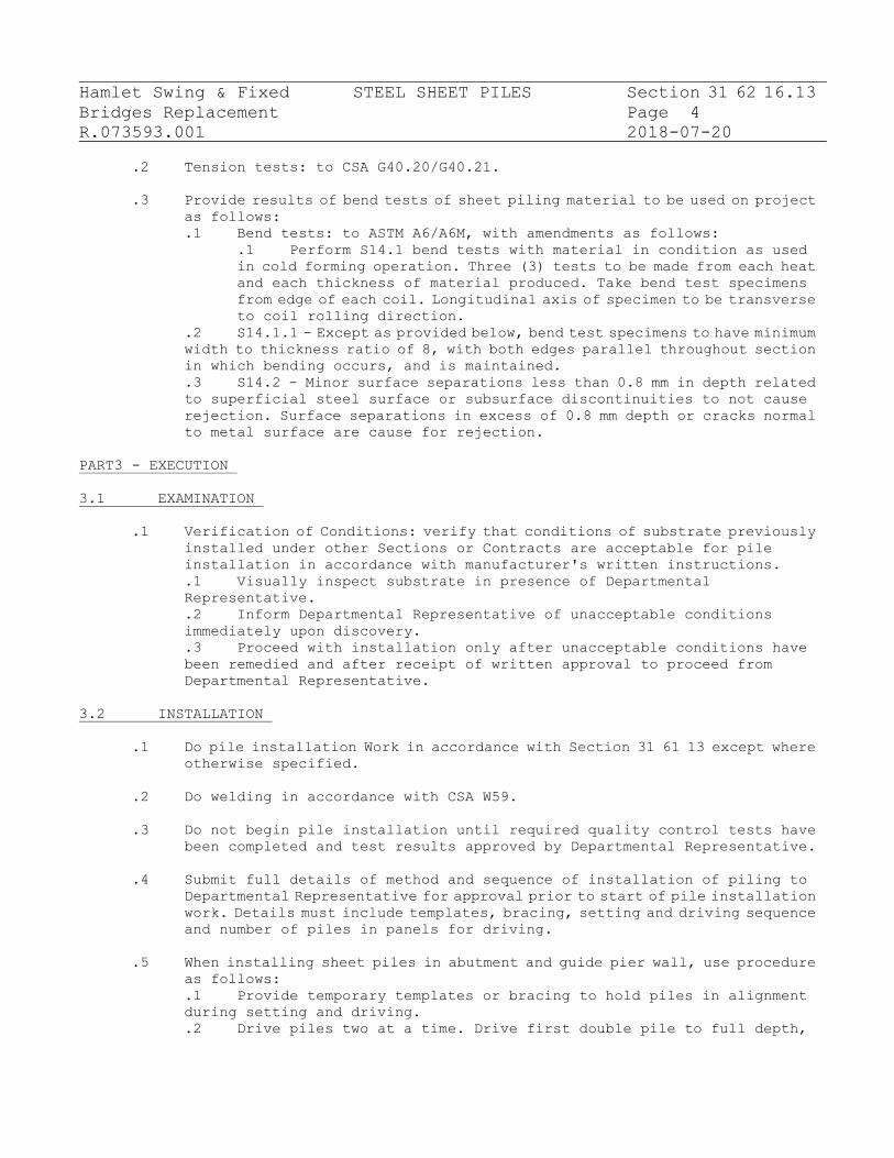
Hamlet Swing & Fixed STEEL SHEET PILES Section 31 62 16.13
Bridges Replacement Page 4
R.073593.001 2018-07-20
.2 Tension tests: to CSA G40.20/G40.21.
.3 Provide results of bend tests of sheet piling material to be used on project
as follows:
.1 Bend tests: to ASTM A6/A6M, with amendments as follows:
.1 Perform S14.1 bend tests with material in condition as used
in cold forming operation. Three (3) tests to be made from each heat
and each thickness of material produced. Take bend test specimens
from edge of each coil. Longitudinal axis of specimen to be transverse
to coil rolling direction.
.2 S14.1.1 - Except as provided below, bend test specimens to have minimum
width to thickness ratio of 8, with both edges parallel throughout section
in which bending occurs, and is maintained.
.3 S14.2 - Minor surface separations less than 0.8 mm in depth related
to superficial steel surface or subsurface discontinuities to not cause
rejection. Surface separations in excess of 0.8 mm depth or cracks normal
to metal surface are cause for rejection.
PART3 - EXECUTION
3.1 EXAMINATION
.1 Verification of Conditions: verify that conditions of substrate previously
installed under other Sections or Contracts are acceptable for pile
installation in accordance with manufacturer's written instructions.
.1 Visually inspect substrate in presence of Departmental
Representative.
.2 Inform Departmental Representative of unacceptable conditions
immediately upon discovery.
.3 Proceed with installation only after unacceptable conditions have
been remedied and after receipt of written approval to proceed from
Departmental Representative.
3.2 INSTALLATION
.1 Do pile installation Work in accordance with Section 31 61 13 except where
otherwise specified.
.2 Do welding in accordance with CSA W59.
.3 Do not begin pile installation until required quality control tests have
been completed and test results approved by Departmental Representative.
.4 Submit full details of method and sequence of installation of piling to
Departmental Representative for approval prior to start of pile installation
work. Details must include templates, bracing, setting and driving sequence
and number of piles in panels for driving.
.5 When installing sheet piles in abutment and guide pier wall, use procedure
as follows:
.1 Provide temporary templates or bracing to hold piles in alignment
during setting and driving.
.2 Drive piles two at a time. Drive first double pile to full depth,

Hamlet Swing & Fixed STEEL SHEET PILES Section 31 62 16.13
Bridges Replacement Page 5
R.073593.001 2018-07-20
then place panel of five to eight double sheet piles in templates and secure
last (end) double pile in location to prevent spreading of piles in panel.
.3 Drive end double pile in panel sufficiently deep into ground to ensure
that it will remain plumb, then, drive remaining double piles in panel to
full depth beginning with double pile next to end double pile and finishing
with double pile next to double pile first driven.
.4 After one panel has been driven, place and drive succeeding panels
in similar manner. Complete driving of end double pile of first panel after
double piles of second panel have been driven.
.6 When installation is complete, face of wall at top of sheet piles to be
within 150 mm of location as indicated and deviation from vertical not to
exceed 1 in 100.
3.3 OBSTRUCTIONS
.1 If obstruction encountered during driving, leave obstructed pile and
proceed to drive remaining piles. Return and attempt to complete driving
of obstructed pile later.
.2 Advise Departmental Representative immediately if impossible to drive
pile to full penetration, and obtain direction from Departmental
Representative on further steps required to complete Work.
3.4 HOLES
.1 Patch holes in sheet pile wall, except where permanent holes are
indicated.
.1 Use plate of material equal to that of piling to patch holes
and overlap not less than hole diameter.
.2 Weld to develop full strength of plate.
.3 No patched holes are permitted in piles in surfaces
.2 Drill any required holes in piling. Do not use flame cutting without
permission of Departmental Representative.
3.5 CUTTING
.1 When flame cutting tops of piles, and flame cutting holes in piles
approved by Departmental Representative, use following procedure:
.1 When air temperature is above 0 degrees C, no pre-heat is
necessary.
.2 When air temperature is below 0 degrees C, pre-heat until steel
25 mm on each side of line of cut has reached a temperature very
warm to hand (approximately 35 degrees C). Temperature indicating
crayon marks may be used to measure temperature.
.3 Use torch guiding device to ensure smooth round holes or
straight edges.
.4 Make cut smooth and free from notches throughout thickness. If
grinding is employed to remove notch or crack, finished radius
to be minimum 5 mm.
3.6 SPLICING
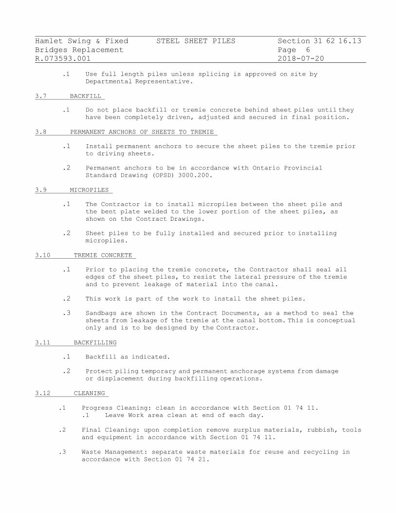
Hamlet Swing & Fixed STEEL SHEET PILES Section 31 62 16.13
Bridges Replacement Page 6
R.073593.001 2018-07-20
.1 Use full length piles unless splicing is approved on site by Departmental Representative.
3.7 BACKFILL
.1 Do not place backfill or tremie concrete behind sheet piles until they have been completely driven, adjusted and secured in final position.
3.8 PERMANENT ANCHORS OF SHEETS TO TREMIE
.1 Install permanent anchors to secure the sheet piles to the tremie prior
to driving sheets.
.2 Permanent anchors to be in accordance with Ontario Provincial
Standard Drawing (OPSD) 3000.200.
3.9 MICROPILES
.1 The Contractor is to install micropiles between the sheet pile and
the bent plate welded to the lower portion of the sheet piles, as
shown on the Contract Drawings.
.2 Sheet piles to be fully installed and secured prior to installing
micropiles.
3.10 TREMIE CONCRETE
.1 Prior to placing the tremie concrete, the Contractor shall seal all
edges of the sheet piles, to resist the lateral pressure of the tremie
and to prevent leakage of material into the canal.
.2 This work is part of the work to install the sheet piles.
.3 Sandbags are shown in the Contract Documents, as a method to seal the
sheets from leakage of the tremie at the canal bottom. This is conceptual only and is to be designed by the Contractor.
3.11 BACKFILLING
.1 Backfill as indicated.
.2 Protect piling temporary and permanent anchorage systems from damage
or displacement during backfilling operations.
3.12 CLEANING
.1 Progress Cleaning: clean in accordance with Section 01 74 11.
.1 Leave Work area clean at end of each day.
.2 Final Cleaning: upon completion remove surplus materials, rubbish, tools
and equipment in accordance with Section 01 74 11.
.3 Waste Management: separate waste materials for reuse and recycling in
accordance with Section 01 74 21.

Hamlet Swing & Fixed STEEL SHEET PILES Section 31 62 16.13
Bridges Replacement Page 7
R.073593.001 2018-07-20
.1 Remove recycling containers and bins from site and dispose of
materials at appropriate facility.
END OF SECTION

Hamlet Swing & Fixed MICROPILES Section 31 63 19
Bridges Replacement Page 1
R.073593.001 2018-07-20
PART 1 - GENERAL
1.1 RELATED REQUIREMENTS
.1 Section 01 35 43 – Environmental Procedures.
.2 Section 01 74 21 - Construction Demolition Waste Management and Disposal
.3 Section 03 20 00 – Concrete Reinforcing.
.4 Section 03 30 00 – Cast-In-Place Concrete.
.5 Section 05 50 00 - Metal Fabrication.
.6 Section 31 23 34 – Excavation for Structure and Backfill to Structure.
.7 Geotechnical Report Repair/Upgrade-Replacement of Hamlet Swing and Fixed
Bridges – Report Number: 1659973, January 19, 2018, Golder Associate.
1.2 DESCRIPTION
.1 The work in this section includes, but is not limited to, the following:
.1 Prepare and submit shop drawings for the micropiles.
.2 Supply all components of the micropiles including but not limited
to high strength steel reinforcement assemblies, grout, steel casing,
bearing plates and nut.
.3 Undertake all testings as specified herein and on the contract
drawings.
.4 The working load for the production anchors shall be as indicated
on the drawings or on reviewed shop drawings.
.5 Micropiles shall be installed using pressure grouting with provisions
for post-grouting. The Contractor is responsible for carrying out the
grouting procedures to obtain the required anchor load.
.6 All access, control of effluent during drilling/grouting and all
cleanup at the conclusion of the work.
1.3 MEASUREMENT PROCEDURES
.1 There shall be no measurement for this work.
.2 Payment will be under the Contract Lump Sum Amount and such payment shall
be full compensation of all labour, equipment and materials necessary to
complete the work.
1.4 REFERENCES
.1 ASTM International (ASTM)
.1 ASTM A722/A722M-12 Uncoated High-Strength Bar for Prestressing
Concrete.
.2 A153 Standard Specification for Zinc Coating (Hot-Dip) on Iron and
Steel Hardware.
.3 A252-10 Standard Specification for Welded and Seamless Steel Pipe

Hamlet Swing & Fixed MICROPILES Section 31 63 19
Bridges Replacement Page 2
R.073593.001 2018-07-20
Piles.
.4 C144-11 Standard Specification for Aggregate for Masonry Mortar.
.5 D1143-07 Standard Test for Deep Foundations Under Static Axial
Compressive Load.
.6 D1784-11 Standard Specification for Rigid PVC Compounds and CPVC
Compounds.
.7 D3689-07 Standard Test Method for Individual Piles Under Static Axial
Tensile Load.
.8 D 4380-84 Standard Test Method for Density of Bentonite Slurries.
.2 CSA International
.1 CSA A23.1-14/A23.2-14, Concrete Materials and Methods of Concrete
Construction/Test Methods and Standard Practices for Concrete.
.2 CSA G30.18-09(R2014), Carbon and Steel Bars for Concrete
Reinforcement.
.3 CSA G40.20-13/G40.21-13, General Requirements for Rolled or Welded
Structural Quality Steel/Structural Quality Steel.
.4 CSA S16-14, Design of Steel Structures.
.5 CSA S6-14 Package, Canadian Highway Bridge Design Code.
.6 CSA W59-13, Welded Steel Construction (Metal Arc Welding).
.7 CSA A283-06 Qualification Code for Concrete Testing Laboratories.
.3 American Welding Society, AWS:
.1 D 1.2 Structural Welding Code – Reinforcing Steel.
.2 D 1.5 Structural Welding Code – Steel.
.4 American Society of Civil Engineers, ASCE:
.1 ASCE 20-96 Standard Guidelines for the Design and Installation of
Pile Foundations.
.5 International Organization for Standardization/International
Electrotechnical Committee, ISO/IEC:
.1 DIS 17025:1999General Requirements for the Competence of the Testing
and Calibration Laboratories.
.6 Others:
.1 Post Tensioning Institute Publications - Recommendations for
Prestressed Rock and Soil Anchors – 1996.
.2 Canadian Foundation Engineering Manual (CFEM), 4th Edition.
.3 Federal Highway Administration Publication No. FHWA NHI–05- 039:
Micropile Design and Construction.
1.4 DEFINITION
.1 For the purposes of this Special Provision, the following definitions apply:
.1 Admixture means a substance added to the grout to either control bleed
and/or shrinkage, improve flowability, reduce water content, retard setting
time, or resist washout.
.2 Alignment Load (AL) means a nominal load applied to a micropile during
testing to keep the testing equipment correctly positioned.
.3 Apparent Free Micropile Length means the length of micropile that
is not bonded to the surrounding ground, as calculated from the elastic
movement data during testing.

Hamlet Swing & Fixed MICROPILES Section 31 63 19
Bridges Replacement Page 3
R.073593.001 2018-07-20
.4 Bond Length means the length of the micropile that is bonded to the
ground and capable of transferring the applied axial loads to the surrounding
soil or rock.
.5 Bond-Breaker means a sleeve placed over the reinforcement steel to
prevent load transfer.
.5 Casing means a steel pipe introduced during the drilling process to
temporarily stabilize the drill hole and/or permanently reinforce the pile.
.6 Centralizer means a device used to centrally locate the reinforcing
element(s) within the casing and/or borehole to ensure that minimum grout
cover is provided.
.7 Central Bar or Central Steel means steel reinforcing bars or pipes
used to strengthen or stiffen the pile, excluding any left-in drill rod
or casing.
.8 Coupler means a device used to transmit load from one partial length
of reinforcement to another.
.9 Creep Movement means the movement that occurs during the creep test
of a micropile under a constant load.
.10 Design Engineer means the Engineer retained by the Contractor who
produces the original design and/or Working Drawings.
.11 Design Checking Engineer means the Engineer retained by the Contractor
who checks the original design and/or Working Drawings.
.12 Design Load (DL) means the anticipated final maximum service load
in the micropile. The design load includes appropriate factors to ensure
that the overall structure has adequate capacity for its intended use.
.13 Duplex Drilling means a drilling system involving the simultaneous
rotation and advancement of (inner) drill rod and (outer) drill casing in
which the cuttings from the inner drill rod exit the borehole via the annulus
between the rod and the casing.
.14 Elastic Movement means the recoverable movement measured during a
micropile test.
.15 Encapsulation means a corrugated or deformed tube protecting the
reinforcing steel against corrosion.
.16 Engineer means a professional engineer, licensed by the Professional
Engineers of Ontario to practice in the Province of Ontario.
.17 Free (Unbonded) Length means the designed length of the micropile
that is not bonded to the surrounding ground or grout during testing.
.18 Micropile means a bored, cast-in-place pile containing steel
reinforcement, designed to accept load (axial, bending or lateral) directly,
and transfer it to an appropriate bearing stratum.
.19 Maximum Test Load (TL) means the maximum load to which the micropile
is subjected during testing.
.20 Overburden means a non-lithified material, natural or placed, which
normally requires cased drilling methods to provide an open borehole to
underlying strata.
.21 Post-Grouting means the injection of additional grout into the load
transfer length of a micropile after the Primary grout has set.
.22 Pre-Production Micropile means a sacrificial micropile that is not
part of the final foundation system and is subjected to load testing to
verify the design and installation procedures.
.23 Primary Grout means Portland cement based grout that is injected into
the micropile hole prior to or after the installation of the reinforcement
to provide the load transfer to the surrounding ground along the micropile
and affords a degree of corrosion protection when the micropile is in

Hamlet Swing & Fixed MICROPILES Section 31 63 19
Bridges Replacement Page 4
R.073593.001 2018-07-20
compression.
.24 Production Micropile means a micropile that forms part of the final
foundation support system to a structure.
.25 Proof Load Test means the incremental loading of a production
micropile, recording the total movement at each increment.
.26 Quality Engineer (QE) means an engineer who has a minimum of five
(5) years’ experience in the field of design and/or installation of
micropiling or alternatively has demonstrated expertise by providing
satisfactory quality verification services for the work at a minimum of
two (2) projects of similar scope to the Contract. The Quality Engineer
shall be retained by the Contractor to certify that the work is in general
conformance with the Contract Documents and to issue Certificate(s) of
Conformance.
.27 Reinforcement Steel means the steel component(s) of the micropile
which accepts and/or resists applied loadings. This includes the central
steel bar and/or the permanent steel casing.
1.5 ACTION AND INFORMATIONAL SUBMITTALS
.1 Submit in accordance with Section 01 33 00.
.2 One (1) week prior to commencing any work associated with the micropile
operation, the Contractor shall submit to the Departmental Representative,
a condition survey of property and structures that may be affected by the
work. The survey shall include, but not be limited to, the locations and
conditions of adjacent properties, buildings, underground structures,
utility services and structures such as houses and buildings adjacent to
the site.
.3 At least three (3) weeks prior to the commencement of the micropile
operations, the Contractor shall submit three (3) copies of the Working
Drawings to the Departmental Representative for information purposes only.
Information to be shown on the Working Drawings shall describe and illustrate
the complete details of the micropile installations, as well as the micropile
testing equipment, test set-up, and reaction system(s) for the
pre-production and production test micropile(s). This information shall
include the following:
.1 Plans, Elevations and Sections (at each foundation element):
.1 Micropile spacing.
.2 Orientation.
.3 Minimum total micropile length.
.4 Casing plunge length.
.5 Uncased bond length.
.6 Design load.
.7 A unique identification number for each micropile.
.8 Micropile components and details.
.2 Materials:
.1 Physical properties of reinforcement steel (central bar and
casing), including mill test reports.
.2 Physical properties of pile top attachment.
.3 Bond length grout materials and mix proportions.
.4 Corrosion protection material physical/mechanical properties
(if any).

Hamlet Swing & Fixed MICROPILES Section 31 63 19
Bridges Replacement Page 5
R.073593.001 2018-07-20
.3 Micropile Installation:
.1 Construction methods.
.2 Work restrictions.
.3 Schedule of major equipment resources.
.4 Sequence of pile installation and coordination of work.
.5 Procedures for monitoring micropile installation.
.6 Type, number and location of pre-production and production load
tests.
.7 Method of evaluation of load test results.
.4 Micropile Construction Details:
.1 Detailed description of the proposed construction
procedures.
.2 Method of drilling the micropile holes and maintaining the
stability of the holes during the micropile installation.
.3 Detailed description of the drilling equipment and
materials including drill bit/auger diameter and lengths, casing
diameter and lengths, flush type, slurry materials or other
materials to facilitate the construction of the micropile hole.
.4 Method of verifying the lengths of micropile holes.
.5 Method of placing and centering the central bar
reinforcement steel including the method used to maintain it in
the centre of the hole over the design bond length.
.6 Detailed description of the grout mixing procedure and the
method of grout installation and placement. The description shall
include the grout pressures and details of the procedure(s) for
assuring that the annulus between the outside of the micropile casing
and bedrock is completely filled with grout during the installation.
.5 All design assumptions, loads, parameters and bond stresses used for
production and test micropiles.
.6 Testing records and evaluation when testing has been completed to
assess bond stress and micropile movement.
.7 All of the above stamped by the Contractor’s Engineer who is licensed
in the Province of Ontario.
.4 The Contractor shall submit to the Departmental Representative at the time
of delivery to the job site, one copy of the certified mill test reports,
indicating that the steel meets the requirements for the appropriate
standards for casing and central bar reinforcement, plates and shapes. The
ultimate strength, yield strength, elongation, and material properties
composition shall be included. For steel pipe used as permanent casing,
or core steel, the Contractor shall submit a minimum of two representative
coupon tests or mill certifications on each lot of material delivered to
the project.
Where mill test certificates originate from a mill outside Canada or the
United States of America the Contractor shall have the information on the
mill certificate verified by testing by a Canadian laboratory. The
laboratory shall be accredited by a Canadian National Accreditation Body
to comply with the requirements of ISO/IEC DIS 17025 for the specific tests
or type of tests required by the material standard specified on the mill
test certificate. The mill test certificates shall be stamped with the
name of the Canadian testing laboratory and appropriate wording stating
that the material conforms to the specified material requirements. The

Hamlet Swing & Fixed MICROPILES Section 31 63 19
Bridges Replacement Page 6
R.073593.001 2018-07-20
stamp shall include the appropriate material specification number, the
date and the signature of an authorized officer of the Canadian testing
laboratory.
One copy of the stress-strain curves representative of the lots to be
used shall be submitted to the Departmental Representative together with
the mill certificates detailed in OPSS 1440.
.5 The Contractor shall submit to the Departmental Representative a suitable,
site specific grout mix design, including details of all materials to be
incorporated, and the procedure for mixing and placing the grout. This
submittal shall include certified test results verifying the acceptability
of the proposed mix designs. The acceptability of the mixes will be further
verified on site prior to production by casting a series of grout cubes.
These cubes are to be tested by the Contractor and the results submitted
to the Departmental Representative.
.6 The Contractor shall submit micropile installation records, signed by the
Quality Engineer, to the Departmental Representative, within 3 business
days after each pile installation (including all test piles and production
piles) is completed. The installation records shall include the following
information:
.1 Pile identification number and location.
.2 Pile drilling duration, including date of installation and start and
finish time.
.3 Pile drilling observations, including nature of and variation in
cuttings return, penetration rates for each 0.5 m of penetration, presence
of boulders or obstructions, connections between holes, top of bedrock.
.4 Information on depth of drilling and soil and rock types encountered,
including description of strata, depth to water, etc.
.5 Sequence of installation.
.6 Inclination and direction.
.7 Final tip elevation.
.8 Casing tip elevation.
.9 Cut-off elevation.
.10 Length and diameters of all components.
.11 Bar length, spacers/coupler details.
.12 Description of unusual installation behaviour, conditions.
.13 Any deviations from the intended parameters, exceptions and “unusual”
events.
.14 Grout pressures attained, where applicable.
.15 Grout mix proportions (grout test results provided at 7, 14 and 28
days).
.16 Grout quantities pumped.
.17 Pile materials and dimensions.
.18 Micropile test records, analysis and details.
.19 As-built drawings showing the location of the piles, their depth and
inclination, and details of their composition shall be submitted within
thirty (30) calendar days of each abutment completion. Locations shall be
surveyed by the Contractor providing northing, easting and elevation.
.7 The Contractor shall submit to the Departmental Representative details of
the micropile load testing, three (3) weeks prior to construction. The

Hamlet Swing & Fixed MICROPILES Section 31 63 19
Bridges Replacement Page 7
R.073593.001 2018-07-20
details shall include the following:
.1 Detailed description of the proposed load testing procedures.
.2 Shop drawings and structural calculations for the design of the pile
load testing, including reaction systems. The structural calculations shall
confirm that the materials will meet the specified load and movement
criteria.
.3 Detailed plans for the set-up method proposed for testing the
pre-production and production micropiles including all necessary drawings
and details to clearly describe the test method and equipment proposed.
Special attention shall be paid to providing adequate structural stability
of the reaction piles/ground anchors and loading frame connections. Special
attention shall be paid to the method of freeing the upper portion of the
test pile from the overburden soils for the pre-production load tests.
.4 Calibration reports for each test jack, pressure gauge, and master
pressure gauge to be used. The calibration tests shall have been performed
by an independent testing laboratory and tests shall have been performed
within one year of the date submitted. Testing shall not commence until
the Departmental Representative has reviewed the jack, pressure gauge and
master pressure gauge calculations.
.5 All of the above submittals for procedures, calculations and
certifications shall have the seal and signature of an Engineer licensed
in the Province of Ontario.
PART 2 - PRODUCTS
2.1 MATERIALS
.1 Water for mixing grout shall be according to Section 03 30 00.
2.2 ADMIXTURES
.1 Admixtures shall be according to Section 03 30 00. Admixtures which control
bleed, allows placement in standing water without washout, improve
flowability, reduce water content, and retard set may be used in the grout
only if the admixture manufacturer certifies that their use will not affect
the required properties of the grout. Expansive admixtures shall only be
added to the grout used for filling sealed encapsulations (if used).
Accelerators and admixtures with chlorides shall not be permitted.
Admixtures shall be compatible with the grout and mixed in accordance with
the manufacturer’s recommendations.
2.3 CEMENT
.1 All cement shall be Type GU General Use hydraulic cement conforming to
Section 03 30 00 requirements.
2.4 FILLER
.1 Inert fillers such as sand may be used in the grout in special situations
(e.g., presence of large voids in the ground, when grout take and travel
are to be limited) and only if the Quality Engineer certifies that their
use will not affect the required properties of the grout.

Hamlet Swing & Fixed MICROPILES Section 31 63 19
Bridges Replacement Page 8
R.073593.001 2018-07-20
2.5 GROUT
.1 The grout mix materials and procedures for placement and testing shall
conform to OPSS 1301, OPSS 1302, OPSS 1303, OPSS 1350 and CSA A23.2-1B.
.2 The Contractor shall provide a stable, homogenous neat cement grout or a
sand cement grout. The grout shall be free of any lumps and not contain
any evidence of poor or incomplete mixing. The grout shall be mixed to the
supplier’s specification. The water/cement ratio of the grout (by weight)
shall not exceed 0.45. The grout shall have the following physical
properties:
.1 A minimum compressive strength of 25 MPa at 7 Days.
.2 A minimum compressive strength of 35 MPa at 28 Days.
.3 No segregation and a bleed of less than 2 percent when allowed to
stand for 1 hour.
.4 Mix design shall be by the Contractor, to suit his production and
testing requirements.
.5 The Contractor shall produce a trial batch and test the grout by
casting cubes, curing the cubes and having them broken in a certified
laboratory.
2.6 REINFORCING
.1 Steel reinforcing bar shall be high strength Threadbar according to OPSS
1440 Grade 517 MPa. Bar shall meet ASTM A722 (Grade 150).
.2 Couplers for steel reinforcing bar shall be as specified by the supplier
of the steel reinforcing bar and shall develop at least 100% of the guaranteed
minimum ultimate strength of the reinforcing bar.
.3 The permanent steel casing shall meet the requirements of API N80 (80 ksi).
.1 New “Structural Grade” (a.k.a. “Mill Secondary”) steel pipe meeting
the above but without Mill Certification is acceptable for use as permanent
casing provided it is free from defects (dents, cracks, tears) and is
accompanied by two coupon tests per truckload confirming it meets the above
requirements.
.2 All casing joints shall be threaded. The casing joints shall develop
at least the required compressive, tensile and/or bending strength used
in the design of the micropile.
.4 Structural steel plates and shapes for pile top attachments shall be
according to CSA G40.21/.20 Grade 350W.
.5 Centralizers shall be fabricated from schedule 40 PVC pipe or tube, steel,
or material that is non-detrimental to the reinforcement steel. Wood shall
not be used.
2.7 SOURCE QUALITY CONTROL
.1 Materials, fabrication and installation will be subjected to Quality
Assurance Inspection by the Departmental Representative or by the
organization appointed by the Departmental Representative to ensure that

Hamlet Swing & Fixed MICROPILES Section 31 63 19
Bridges Replacement Page 9
R.073593.001 2018-07-20
the Contractor follows specifications, shop drawings and good engineering
practice.
PART3 - EXECUTION
3.1 EQUIPMENT
.1 The limited working spacing at the abutments and piers, and the soft/loose
subsurface conditions at the abutments may limit the ability to utilize
large/heavy pile driving equipment; therefore, suitable equipment shall
be used at the site.
.2 All equipment for the installation, testing and monitoring of the
pre-production (verification) and production micropiles shall be suitable
for the intended purposes and capable of working on the site under the
prevailing access and clearance conditions.
.3 The equipment used shall be capable of installing and grouting the micropiles
to the prescribed depths or elevations without damage to the pile materials
or to the adjacent structures.
.4 All grout mixers, pumps and hoses shall be of an adequate capacity and shall
be sized to enable the grout to be pumped in one continuous operation, while
keeping the grout in constant agitation prior to pumping, and to allow
continuous grouting of an individual micropile within one hour.
.1 A high speed, high shear, colloidal grout mixer with a gauge to measure
the quantity of water discharged into the mixer shall be used. A paddle
mixer is not acceptable table.
.2 The grout pump(s) shall be equipped with a pressure gauge to monitor
grout pressures of at least 1 MPa or twice the actual grouting pressures
used, whichever is greater.
.5 Micropile testing equipment shall be capable of loading the test piles to
the maximum specified test load (TL) within the rated capacity.
.1 The equipment shall be capable of loading the pile in increments so
that the load on the pile can be increased or decreased in accordance with
the test procedures outlined in the Contract Documents.
.2 Dial gauges shall have at least a 75 mm travel and longer gauge stems
or sufficient gauge blocks shall be provided to allow for greater travel
where required. Gauges shall have precision of at least 0.02 mm.
.3 Dial gauges shall allow the measurement of total micropile movement
at every load increment to be read to the nearest 0.02 mm increment. The
gauge shall have sufficient travel to record the total pile movement at
Test Load without the need to reset at an interim point.
.4 Loading equipment shall be calibrated within an accuracy of +/-2%
immediately prior to use.
.5 Current calibration curves, bearing the seal and signature of an
Engineer shall be provided for all gauges and jacks.
3.2 CONSTRUCTION
.1 The Contractor shall be responsible for the material, fabrication,
installation, testing and monitoring of the test micropiles and the

Hamlet Swing & Fixed MICROPILES Section 31 63 19
Bridges Replacement Page 10
R.073593.001 2018-07-20
production micropiles. In addition, for non-Owner designed reaction
piles/ground anchors, the Contractor shall be responsible for design
parameters and the design of the reaction piles/ground anchors.
.2 The drilling and installation method shall allow for all drilled holes
to be inspected for cleanliness, depth and diameter prior to placement
of any grout and pile reinforcement steel (i.e. permanent casing and
reinforcing bar).
.3 The Contractor shall not proceed with the installation of production
micropiles until the completion of the pre-production load tests and
until approval has been given by the Departmental Representative.
3.3 SUBSURFACE CONDITIONS
.1 A foundation Investigation Report that describes the subsurface conditions
for the project is available, as specified elsewhere in the Contract. The
Departmental Representative warrants that the information provided in the
Foundation Investigation Report can be relied upon with the following
limitations and exceptions:
.1 Any interpretation of data or opinions expressed in the reports is
not warranted.
.2 Although the raw measured data presented is warranted, the Contractor
must satisfy itself as to the sufficiency of the information presented for
the intended construction purpose and obtain any updating or additional
information as required to facilitate the deep foundation works.
3.4 TRANSPORTATION, HANDLING, STORAGE
.1 Casings and reinforcing bar shall be transported, stored and handled in
such a manner that damage and distortion is prevented and that the strength
and integrity are maintained.
.2 All materials, including cement, additives for grout and pile reinforcement
steel (reinforcing bar and casing) shall be stored off-ground, under cover
and protected against moisture and directly from the elements.
.3 Lifting of any casings and bar reinforcement shall not cause excessive
bending.
3.5 TESTING REQUIREMENTS
.1 The Contractor shall be responsible for the design of the pile load testing
set-up including the reaction systems, the reaction piles/ground anchors
and all loading frames and connections.
.1 An ultimate geotechnical resistance factor = 0.5 for the axial
geotechnical capacity of the micropiles should be used based on the
recommendation in CHBDC (2014) and in Section 5.9.2 (FHWA/NHI 2005),
considering the micropile bond zone will be formed in the competent strong
to very strong bedrock, and assuming at least one (1) verification test
should be conducted prior to commencing production micropile installation.
.2 In consideration of the potential for aggressive ground conditions

Hamlet Swing & Fixed MICROPILES Section 31 63 19
Bridges Replacement Page 11
R.073593.001 2018-07-20
at the site, it is recommended to have a minimum 1.6 mm section loss (all
around) be included in the design of the outer casing of the micropiles.
.3 The reaction piles/ground anchors and the reaction systems shall be
designed to safely withstand the applied loads specified in the Contract
Documents.
.4 The design assumptions shall accurately represent the subsurface
conditions prevalent at the site.
.5 Except as specified herein, the reaction piles/ground anchors shall
be designed in accordance with the design recommendations of the Post
Tensioning Institute Recommendations for Prestressed Rock and Soil Anchors
and the FHWA Publication NHI-05-039 (most current version).
.6 The reaction piles or ground anchors shall be located no closer than
2 m to the test micropiles.
.7 The maximum load in the reaction piles/ground anchors shall not exceed
80% of the guaranteed minimum ultimate tensile strength of the central bar
reinforcement or tendon.
.8 The Contractor shall make provisions, as appropriate and necessary,
to ensure safety and structural stability of the reaction piles or ground
anchors and their connection to the load frame.
.2 Pre-production tests shall be carried out on sacrificial test micropile(s).
Verification tests and proof tests shall be carried out on production
micropile(s). The micropile load testing shall be carried out according
to the Working Drawings and as specified herein.
.3 The Contractor shall provide to the Departmental Representative a minimum
of three (3) Working Days’ notice of when the load tests will be carried
out. The load tests shall be conducted at a time mutually acceptable to
the Contractor and Departmental Representative.
.4 The testing shall not be performed until after the grout in the micropiles
(or reaction piles/ground anchors) has reached a minimum 7 Days unconfined
compressive strength of 25 MPa.
.5 The load tests shall be closely monitored for the duration of the test by
the Contractors Quality Engineer and the test results recorded and submitted
to the Departmental Representative.
.6 The layout of the reference systems and testing equipment required for
testing shall be as detailed on the Working Drawings prepared by the
Contractor and as specified herein.
.1 The Contractor shall supply a suitable means for providing independent
reference beams for measuring micropile head movement, jack, electronic
load cell, dial gauges or electronic displacement transducers, anchor
extension, and any other hardware necessary to carry out the load tests.
A minimum of 3 dial gauges or electronic displacement transducers and piano
wire, is required. Dial gauges or displacement transducers shall have an
accuracy of ±0.0254 mm (0.001 in). Load cells shall have an accuracy of
±2% of the maximum test load. The calibration curve between the jack pressure
and the load shall be submitted to the Departmental Representative for
information purposes.
.2 All reference beams shall be independently supported with the support
firmly embedded in the ground at a distance of not less than 2.5 m from
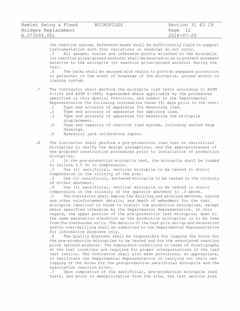
Hamlet Swing & Fixed MICROPILES Section 31 63 19
Bridges Replacement Page 12
R.073593.001 2018-07-20
the reaction system. Reference beams shall be sufficiently rigid to support
instrumentation such that variations in readings do not occur.
.3 All gauges, scales and reference points attached to the micropile
(or reaction piles/ground anchors) shall be mounted so as to prevent movement
relative to the micropile (or reaction piles/ground anchors) during the
test.
.4 The jacks shall be secured with chains to provide adequate protection
to personnel in the event of breakage of the micropile, ground anchor or
loading system.
.7 The Contractor shall perform the micropile load tests according to ASTM
D-1143 and ASTM D-3689, superseded where applicable by the procedures
specified in this Special Provision, and submit to the Departmental
Representative the following information three (3) days prior to the test:
.1 Type and accuracy of apparatus for measuring load.
.2 Type and accuracy of apparatus for applying load.
.3 Type and accuracy of apparatus for measuring the micropile
displacement.
.4 Type and capacity of reaction load system, including sealed shop
drawings.
.5 Hydraulic jack calibration report.
.8 The Contractor shall perform a pre-production load test on sacrificial
micropiles to verify the design assumptions, and the appropriateness of
the proposed construction procedures prior to installation of production
micropiles.
.1 In the pre-production micropile test, the micropile shall be loaded
to failure 2.5 DL in compression.
.2 One (1) sacrificial, vertical micropile to be tested in static
compression in the vicinity of the pier.
.3 One (1) sacrificial, battered micropile to be tested in the vicinity
of either abutment.
.4 One (1) sacrificial, vertical micropile to be tested in static
compression in the vicinity of the opposite abutment to .3 above.
.5 The Contractor shall employ the drilling and grouting methods, casing
and other reinforcement details, and depth of embedment for the test
micropile identical to those to install the production micropiles, except
where specified otherwise by the Departmental Representative. In this
regard, the upper portion of the pre-production test micropile, down to
the same excavation elevation as the production micropiles is to be free
from the overburden soils. The details of the test pile set-up and excavation
and/or over-drilling shall be submitted to the Departmental Representative
for information purposes only.
.6 The Quality Engineer shall be responsible for logging the holes for
the pre-production micropiles to be tested and for the associated reaction
piles (ground anchors). The subsurface conditions in terms of stratigraphy
at the test locations are required for proper interpretations of the load
test results. The Contractor shall also make provisions, as appropriate,
to facilitate the Departmental Representative in carrying out their own
logging of the holes for the pre-production sacrificial micropile and the
association reaction piles.
.7 Upon completion of the sacrificial, pre-production micropile load
tests, and prior to demobilization from the site, the test section area

Hamlet Swing & Fixed MICROPILES Section 31 63 19
Bridges Replacement Page 13
R.073593.001 2018-07-20
is to be restored to near original conditions as per the direction of the
Departmental Representative.
.8 Once the pre-production tests are complete and all test data provided
to the Departmental Representative by the Contractor’s Quality Engineer,
the Departmental Representative shall have two (2) days to review the data
before the Contractor commences installing production microplies.
.9 The Contractor shall perform a pre-production micropile axial
compression load test on each of the reaction piles (ground anchors).
.10 The loading test increments for the reaction piles shall be as shown
in Table 1, Verification Test Load Schedule except on the fourth cycle the
loading shall be reviewed after 1.75DL to:
Table 1 - Verification Test Load Schedule
Load Minimum Hold Time
(Minutes)
1.9DL 2.5
2.0DL 2.5
2.1DL 2.5
2.2DL 2.5
2.3DL 2.5
2.4DL 2.5
2.5DL 10*
2.0DL 5
1.5DL 5
1.0DL 5
0.5DL 5
* Hold until acceptance criterion for creep movement is satisfied
as specified in this specification.
.9 The Contractor shall perform verification tests on selected production
micropiles as follows:
.1 The Contractor shall submit to the Departmental Representative a
proposal recommending the production micropile(s) to be selected for
testing, however, the final selection will be up to the Departmental
Representative.
.2 In the verification micropile test, the production micropile shall
be tested to 200% of its Design Load (DL).
.3 The selected micropiles for proof testing will be tested no sooner
than 7 Days after installation to allow the grout to reach sufficient
strength. It is noted that the use of adjacent vertical micropiles as
reaction anchors is acceptable, provided that the minimum spacing
requirements between the reaction piles and the test pile (as defined in
Section 7.06.02) can be satisfied. The reaction system, including any
reaction anchors, if necessary, is to be entirely designed by the Contractor
and submitted to the Departmental Representative for information purposes.
.4 The Contractor shall set-up the reaction frame and load test set-up,
complete with jacks, load cells and gauges in a manner similar to the
pre-production load tests. The Contractor shall repair any previously
installed production micropiles that may have been damaged during the course
of proof load testing to the approval of the Departmental Representative
and at no cost to the Owner.

Hamlet Swing & Fixed MICROPILES Section 31 63 19
Bridges Replacement Page 14
R.073593.001 2018-07-20
.10 The Contractor shall perform proof tests on selected micropiles after the
verification tests are completed and the results interpreted.
.1 The Contractor shall submit to the Departmental Representative a
proposal recommending the production micropile(s) to be selected for
testing, however, the final selection will be up to the Departmental
Representative.
.2 In the proof micropiles test, the production micropile shall be tested
to 160% of its Design Load.
.3 Two (2) battered production micropile from each of the west and east
abutments (total four (4)) to be tested in static compression.
.4 The selected micropiles for proof testing will be tested no sooner
than 7 Days after installation to allow the grout to reach sufficient
strength and allow a minimum of 3 days to interpret the verification test
data. It is noted that the use of adjacent vertical micropiles as reaction
anchors is acceptable, provided that the minimum spacing requirements
between the reaction piles and the test pile (as defined in Section 7.06.02)
can be satisfied. The reaction system, including any reaction anchors, if
necessary, is to be entirely designed by the Contractor and submitted to
the Departmental Representative for information purposes.
.5 The Contractor shall set-up the reaction frame and load test set-up,
complete with jacks, load cells and gauges in a manner similar to the
pre-production load tests. The Contractor shall repair any previously
installed production micropiles that may have been damaged during the course
of proof load testing to the approval of the Departmental Representative
and at no cost to the Owner.
.11 Verification Test Procedures and Measurement:
.1 The Contractor shall load the tested micropile(s) to a minimum of
200 % of the design load (DL) (i.e., 2.0 DL). The jack shall be positioned
at the beginning of the test such that the unloading and repositioning of
the jack during the test will not be required. The Contractor shall apply
an Alignment Load (AL) to the pile prior to setting the movement recording
devices. This Alignment Load shall be no more than 10 % of the Design Load
(i.e., 0.1 DL). Dial gauges shall be zeroed at the first setting of the
AL.
.2 The Contractor shall carry out the axial load test by loading the
micropile and recording the micropile head movement according to the load
increments presented in Table 3. The Contractor shall maintain each load
increment for the minimum duration indicated in Table 3 or until the
settlement rate is less than 1 mm/log cycle of time.
Table 3 – Verification Test Load Schedule
Load Minimum Hold Time
(Minutes)
AL 2.5
0.15 DL 2.5
0.30 DL 2.5
0.50 DL 2.5
AL 1
0.15 DL 1
0.45 DL 1

Hamlet Swing & Fixed MICROPILES Section 31 63 19
Bridges Replacement Page 15
R.073593.001 2018-07-20
0.60 DL 2.5
0.75 DL 2.5
0.90 DL 2.5
1.00 DL 2.5
AL 1
0.15 DL 1
1.00 DL 1
1.15 DL 2.5
1.30 DL 10*
1.45 DL 2.5
AL 1
0.15 DL 1
1.45 DL 1
1.60 DL 1
1.75 DL 2.5
1.90 DL 2.5
2.00 DL 10*
1.50 DL 5
1.00 DL 5
0.50 DL 5
AL 5
AL = Alignment Load DL = Design Load
* Hold until acceptance criterion for creep movement is satisfied
as specified in 3.5.11.2.
.3 The movement of the test pile (or reaction pile/ground anchor) shall
be measured at each load increment. The load hold period shall be started
as soon as the test load is applied. The pile movement shall be measured
and recorded, with respect to a fixed reference, at 1, 2, 3, 4, 5 and 10
minutes, and at 10 minute increments thereafter (if applicable). For
durations longer than 60 minutes, take readings at 30 minute intervals (if
applicable).
.12 Verification Test Acceptance Criteria:
.1 Sustaining the axial load with no more than 15 mm total vertical
movement (at 0.78 DL) and with no more than an additional 3 mm of total
vertical movement (from 0.78 DL to 1.00 DL) at the top of the pile, as measured
relative to the top of the pile prior to the start of testing. If an Alignment
Load is used, then the allowable movement will be reduced by multiplying
by a factor of (DL-AL)/DL.
.2 Creep rate at the end of the 2.0 DL increment on Axial Test micropiles
not greater than 1 mm/log cycle time from 1 to 10 minutes or 2 mm/log cycle
time from 5 to 60 minutes and having a linear or decreasing creep rate.
.3 Failure does not occur at the 2.00 DL axial load. Failure is defined
as the slope of the applied load versus deflection (at end of load increment)
curve exceeding 0.15 mm/kN.
.4 The above is under the assumption that the test pile has been installed
in accordance with the specifications and drawings to a proper standard
of care.
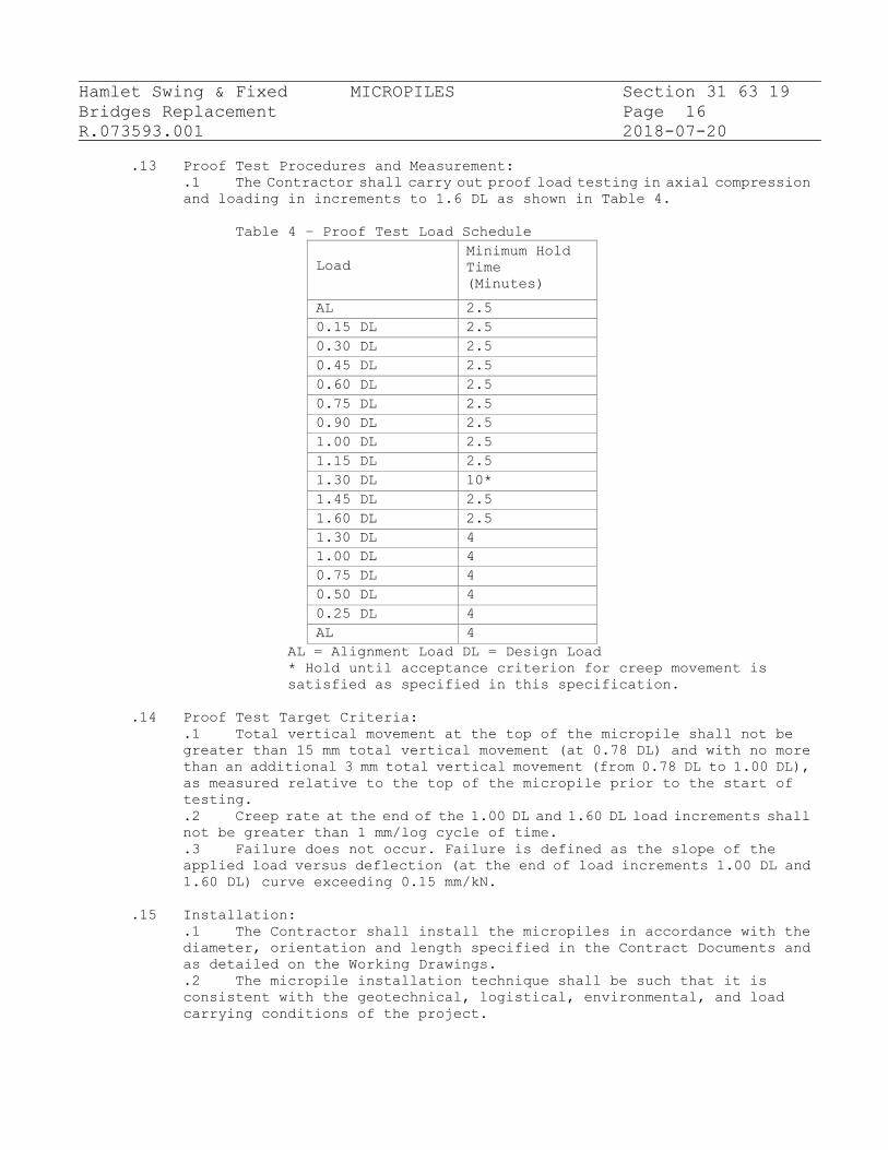
Hamlet Swing & Fixed MICROPILES Section 31 63 19
Bridges Replacement Page 16
R.073593.001 2018-07-20
.13 Proof Test Procedures and Measurement:
.1 The Contractor shall carry out proof load testing in axial compression
and loading in increments to 1.6 DL as shown in Table 4.
Table 4 – Proof Test Load Schedule
Load Minimum Hold
Time
(Minutes)
AL 2.5
0.15 DL 2.5
0.30 DL 2.5
0.45 DL 2.5
0.60 DL 2.5
0.75 DL 2.5
0.90 DL 2.5
1.00 DL 2.5
1.15 DL 2.5
1.30 DL 10*
1.45 DL 2.5
1.60 DL 2.5
1.30 DL 4
1.00 DL 4
0.75 DL 4
0.50 DL 4
0.25 DL 4
AL 4
AL = Alignment Load DL = Design Load
* Hold until acceptance criterion for creep movement is
satisfied as specified in this specification.
.14 Proof Test Target Criteria:
.1 Total vertical movement at the top of the micropile shall not be
greater than 15 mm total vertical movement (at 0.78 DL) and with no more
than an additional 3 mm total vertical movement (from 0.78 DL to 1.00 DL),
as measured relative to the top of the micropile prior to the start of
testing.
.2 Creep rate at the end of the 1.00 DL and 1.60 DL load increments shall
not be greater than 1 mm/log cycle of time.
.3 Failure does not occur. Failure is defined as the slope of the
applied load versus deflection (at the end of load increments 1.00 DL and
1.60 DL) curve exceeding 0.15 mm/kN.
.15 Installation:
.1 The Contractor shall install the micropiles in accordance with the
diameter, orientation and length specified in the Contract Documents and
as detailed on the Working Drawings.
.2 The micropile installation technique shall be such that it is
consistent with the geotechnical, logistical, environmental, and load
carrying conditions of the project.

Hamlet Swing & Fixed MICROPILES Section 31 63 19
Bridges Replacement Page 17
R.073593.001 2018-07-20
.3 The micropiles will be installed in close proximity to each other.
The Contractor shall carry out the drilling and grouting works in such a
manner as to prevent any damage to previously installed micropiles, to
prevent any loss of ground, and to prevent ground movement at the adjacent
structure.
.4 The available working space is limited. The Contractor shall inspect
the work area to ensure that adequate access and headroom are available
for the proposed equipment and procedures for the micropile installation
work.
.5 The Contractor shall employ drilling equipment and methods suitable
for drilling through the anticipated subsurface conditions to be
encountered, and cause no damage to these conditions or any overlying or
adjacent structure or service. The drill hole must be open to the defined
nominal diameter, full length, prior to installing reinforcement steel and
prior to placing grout. The Contractor shall use steel casing during drilling
to the rock level and installation as required. Bentonite slurries to
stabilize the holes are not permitted.
.6 The Contractor shall determine and schedule all installation
techniques such that there will be no interconnection or damage to previously
installed micropiles.
.7 The Contractor shall be responsible for determining the number of
centering devices required. As a minimum, centralizers shall be provided
at 3 m centre maximum spacing on reinforcing bar. The uppermost centralizer
shall be located a maximum of 1.5 m from the top of the micropile.
Centralizers shall permit the free flow of grout without misalignment of
the reinforcement.
.8 The central bar reinforcement steel with centralizers shall be lowered
into the stabilized, open and unobstructed drill holes to the desired depth.
.9 All pile top elevations shall be surveyed by the Contractor and
adjusted to ensure all installed micropiles are installed to the planned
elevations.
.10 The pile reinforcement steel connections (splices) shall be
constructed using mechanical connectors only, to develop the required design
strength of the pile section. The proposed pile splice/connections shall
be submitted to the Contract Administrator, for information purposes only,
prior to use.
.11 Reinforcement steel bar connections shall not be in the same plane
as casing connections/splices. Secure lengths of casing and reinforcement
steel central bar to be joined in proper alignments and in such a manner
that causes no eccentricity between the axes of the two joined lengths or
the angle between them.
.16 Grouting:
.1 The contractor should provide to the Departmental Representative a
grout quality control plan, at a minimum including cube or cylinder
compression testing and grout density (water/cement ratio) testing for
review prior to the construction.
.2 The grout shall be installed as specified in the Contract Documents
and as detailed on the stamped Working Drawings provided by the Contractor.
.3 The Contractor shall provide systems and equipment to measure the
grout quality and pumping pressure during the grouting operations.
.4 After drilling, the Contractor shall flush the hole to remove drill
cuttings and/or other loose debris.

Hamlet Swing & Fixed MICROPILES Section 31 63 19
Bridges Replacement Page 18
R.073593.001 2018-07-20
.5 As soon as practical after completion of drilling and installation
of reinforcement steel, the Contractor shall inject the grout from the lowest
point of the drill hole (by tremie methods) until clean, pure grout flows
from the top of the micropile (to be verified by specific gravity testing
with a Baroid mud balance). The tremie grout may be pumped through grout
tubes or drill rods.
.6 During grouting, the exit of the tremie pipe is to be kept at least
3 m below the level of the grout in the hole.
.7 Subsequent to tremie grouting, all installation operations associated
with completion of the micropile must ensure complete continuity of the
grout column. The use of compressed air to directly pressurize the fluid
grout is not permissible. The grout pressures and grout take volumes shall
be controlled for each stage of each pile to prevent excessive heave or
fracturing in the foundation soils, rock formations or adjacent structure.
The entire micropile shall be grouted to the design cut-off level through
the tremie grout tube(s). Grout volumes per micropile shall be calculated
and compared with the theoretical volume to confirm minimal grout loss into
the rock.
.8 The grout within the micropiles shall attain the minimum design
strength prior to being loaded.
.9 Any micropiles not installed according to the specifications shall
be replaced, or otherwise remediated appropriately. The cost of replacement
and any required foundation modifications are to be carried out at no
additional cost to the Owner.
.10 If necessary, the Contractor shall undertake cold weather protection
requirements, preparation and protection in accordance with CSA CAN3-A23.1.
The temperature of the grout during mixing and pumping shall be maintained
between 10ºC and 30ºC.
.11 Any grout mixture showing evidence of dampness, lumps, harden pieces,
or contamination shall not be incorporated in the work.
.17 Grout Testing:
.1 The Contractor shall be responsible for testing of bleeding,
preparation, initial storage and testing of grout cubes for determination
of compressive strength.
.2 The Contractor shall employ staff from a testing company certified
according to CSA A283 - Certification for Additional Tests 1B, by an
organization accredited by the Standards Council of Canada, to carry out
testing for bleeding, making and curing of grout cubes and early strength
determination.
.3 Making of grout cubes for compressive strength test and testing of
bleeding, shall be done on a level, vibration free surface.
.4 The Contractor shall perform specific gravity testing using a Baroid
mud balance following ASTM D4380-84 on the grout utilized for each and every
micropile.
.5 The testing for bleed of the grout shall be according to CSA A23.2-
1B.
.6 Prior to the grouting operation, in the presence of the Quality
Engineer and the Departmental Representative, a trial batch shall be mixed
and the grout tested for bleed, to ensure that the grout meets the
requirements specified in the Contract Documents. The trial batch of grout
shall not be used in the actual grouting operation unless it meets the
requirements for bleed as specified herein.
Hamlet Swing & Fixed MICROPILES Section 31 63 19
Bridges Replacement Page 19
R.073593.001 2018-07-20
.7 During the grouting operation, bleeding measurements shall be
performed on the grout sampled at the mixer. The measurements shall be
performed at least once a day and as requested by the Contract Administrator.
.8 The bleed test results shall be submitted to the Departmental
Representative in writing at the end of each calendar day. The test results
that indicate the grout is not meeting the requirements of the Contract
Documents shall be reported immediately to the Departmental Representative
and the grouting operation halted until the cause of the problem is
identified and corrected.
.9 Grout cubes shall be prepared as follows on site from the grout pumped
into the micropile:
.1 Three sets of grout cubes, consisting of three cubes each, shall
be made each day the grouting operations are carried out.
.2 The grout cubes shall be prepared and stored according to CSA
A23.2-1B, and shall not be moved prior to demoulding.
.3 The grout cubes shall be demoulded and transported to the
laboratory within 24 hours ± 4 hours.
.4 The grout cubes shall be transported in a sealed white opaque
plastic bag containing at least 250 mL of water and maintained at
a temperature between 15°C and 25°C.
.5 Compressive strength testing shall be carried out on the grout
cubes according to CSA A23.2-1B at 3, 7 and 28 Days and the test results
provided to the Departmental Representative.
.18 Tolerances:
.1 The allowable tolerances are as follows:
.1 Centreline of the installed micropiles, for micropiles that
are not combined with sheet piles, shall not be more than 75 mm from
that shown on the Contract Drawings.
.2 Centreline of the installed micropiles that are combined with
the abutment sheet piles shall be installed such that they match the
sheet pile layout and micropile sleeves that are installed on the
inside face of the sheet piles.
.3 Micropile-hole alignment shall be within 2 % of the total-length
plan alignment.
.4 Top elevation of micropile shall be within +25 mm or -50 mm
maximum of the vertical design elevation.
.5 Centreline of central bar reinforcement shall not be more than
19 mm from centerline of micropile.
.19 Quality Control:
.1 In addition to the information identified above, the Contractor’s
Quality Engineer for micropile installation shall:
.1 Provide all test results (including graphs of force
/displacement) and the pile pre-production, verification and proof
testing. The Certificate of Conformance for each test shall indicate
the results meet the general conformance of the specifications.
.2 At the conclusion of installation of the micropiles, provide
all identical deliverables in this section and a Certificate of
Conformance that the micropile installation has been completed in
general conformance with the Contract requirements.
END OF SECTION

Hamlet Swing & Fixed TREE AND SHRUB PRESERVATION Section 32 01 90.33
Bridges Replacement
Page 1
R.073593.001 2018-07-20
PART 1 – GENERAL
1.1 REFERENCES
.1 Department of Justice Canada (Jus).
.1 Canadian Environmental Protection Act (CEPA), 1999, c. 33.
.2 Fertilizers Act (R.S. 1985, c. F-10).
.3 Fertilizers Regulations (C.R.C., c. 666).
.4 Transportation of Dangerous Goods Act (TDGA), 1992, c. 34.
.2 Health Canada - Pest Management Regulatory Agency (PMRA).
.1 National Standard for Pesticide Education, Training and
Certification in Canada (2004).
.3 Health Canada/Workplace Hazardous Materials Information System
(WHMIS).
.1 Material Safety Data Sheets (MSDS).
.4
.5
ASTM A1064/A1064M-17, Standard Specification for Carbon-Steel Wire
and Welded Wire Reinforcement, Plain and Deformed, for Concrete.
Designated Sources of Materials (DSM):
http://www.roadauthority.com/mpl/mpl.asp?MPIShortName=MTO+DSM
1.2 QUALITY ASSURANCE
.1 Health and Safety:
.1 Do construction occupational health and safety in accordance
with Section 01 35 29.
1.3 SCHEDULING
.1 Obtain approval from Departmental Representative of schedule
indicating beginning of Work.
1.4 MAINTENANCE DURING WARRANTY PERIOD
.1 From time of acceptance by Departmental Representative to end
of warranty period, perform following maintenance operations.
.1 Water to maintain soil moisture conditions for optimum
growth and health of plant material without causing erosion.
.2 Apply pesticides in accordance with National Standard for
Pesticide Education, Training and Certification in Canada,
Federal, Provincial and Municipal regulations as and when
required to control insects, fungus and disease. Obtain product
approval from Departmental Representative prior to application.
.3 Apply fertilizer in early spring at manufacturer's
suggested rate.
Hamlet Swing & Fixed TREE AND SHRUB PRESERVATION Section 32 01 90.33
Bridges Replacement
Page 2
R.073593.001 2018-07-20
.4 Remove dead, broken or hazardous branches from plant
material.
PART 2 - PRODUCTS
2.1 MATERIALS
.1 Anti-desiccant: commercial, wax-like emulsion.
.2 Filter Cloth: Biodegradable burlap.
.3 Wood posts: 38 x 89 x 2400 mm length, untreated wood.
.4 Welded wire fabric (WWF): 100 x 100 mm to ASTM A1064/A1064M-17.
PART 3 – EXECUTION
3.1 IDENTIFICATION AND PROTECTION
.1 Do construction occupational health and safety in accordance with
Section 01 35 29.
.2 Identify plants and limits of root systems to be preserved as approved
by Departmental Representative.
.3 Protect plant and root systems from damage, compaction and
contamination resulting from construction as approved by Departmental
Representative.
.4 Ensure no pruning is done inside drip line. If pruning inside drip
line is required consult an aborist or Canadian Certified
Horticultural Technician (CCHT) as approved by Departmental
Representative.
3.2 ROOT CURTAIN SYSTEM
.1 Identify limits for required construction excavation as approved by
Departmental Representative.
.2 Prior to construction excavation, hand dig trench minimum 500 mm
wide x 1500 mm deep, along perimeter of excavation limits.
.3 Prune exposed roots cleanly at side of trench nearest plants to be
preserved. Pruned ends to point obliquely downwards.
.4 Install wooden posts and welded wire fabric against construction edge
of trench.

Hamlet Swing & Fixed TREE AND SHRUB PRESERVATION Section 32 01 90.33
Bridges Replacement
Page 3
R.073593.001 2018-07-20
.5 Securely attach Type 2 filter fabric on plant side of wire mesh.
.6 Prepare homogeneous mixture of fertilizer, parent material and organic
matter.
.1 Add organic matter to mixture to achieve 7-9%
organic matter content by weight.
.2 Incorporate with mixture grade 2:12:8 ratio
fertilizer (dry) at rate of 1.5 kg/m3.
.7 Backfill with homogeneous mixture between curtain wall and plants to
be preserved in layers not exceeding 150 mm in depth. Compact each
layer to 85% Standard Proctor Maximum Dry Density.
.8 Protect root curtain from damage during construction operations.
.9 Water plants and root curtain sufficiently during construction to
maintain optimum soil moisture condition until backfill operations
are complete.
.10 Protect root curtain before backfill operations. Ensure root curtain
is cut down to 300 mm below finished grade and remove cut material.
3.3 ANTI-DESICCANT
.1 Apply anti-desiccant to foliage where applicable and as directed by
Departmental Representative.
END OF SECTION

Hamlet Swing & Fixed GRANULAR “A” Section 32 11 18
Bridges Replacement
Page 1
R.073593.001 2018-07-20
PART 1 - GENERAL
1.1 Measurement Procedures
.1 Payment for the work of supplying and placing Granular 'A' shall
be made under the unit price item, "Granular A" (by the tonne)
and shall include the costs for all labour, equipment and
material necessary to complete the work of installing Granular
'A' in accordance with these Specifications and the Contract
Drawings.
1.2 Related Sections
.1 Section 31 23 10 - Earth Excavation.
.2 Section 31 05 17 - Aggregate Materials.
1.3 References
.1 OPSS.PROV 501 November 2014, Compacting
.2 OPSS.PROV 1010 April 2013, Aggregates – Base, Subbase, Select
Subgrade, and Backfill Material
.3 Designated Sources of Materials (DSM):
http://www.roadauthority.com/mpl/mpl.asp?MPIShortName=MTO+DSM
1.4 Delivery, Storage and Handling
.1 Deliver and stockpile aggregates in accordance with Section 31 05
17.
PART 2 - PRODUCTS
2.1 Materials
.1 Granular 'A' shall be in accordance with the provisions of
OPSS.PROV 1010 April 2013, Aggregates – Base, Subbase, Select
Subgrade, and Backfill Material. Maximum aggregate size of 19 mm.
PART 3 - EXECUTION
3.1 General
.1 All granular material shall be placed in small lifts, not to
exceed 150 mm, that can be fully compacted to 100% standard
proctor density in accordance with the technical provisions of
OPSS.PROV 501, Compacting.
END OF SECTION

Hamlet Swing & Fixed GRANULAR “B” TYPE II Section 32 11 19
Bridges Replacement
Page 1
R.073593.001 2018-07-20
PART 1 - GENERAL
1.1 Measurement Procedures
.1 Payment for the work of supplying and placing "Granular 'B'" Type
II shall be made under the unit price item, "Granular B type II"
(by the tonne) and shall include all costs for labour, equipment
and material necessary to complete the work of installing
Granular 'B' Type II in accordance with these Specifications and
the Contract Drawings.
1.2 Related Sections
.1 Section 31 23 10 - Earth Excavation
.2 Section 31 05 17 - Aggregate Materials
.3 Section 32 11 18 - Granular 'A'
1.3 References
.1 OPSS.PROV 501 November 2014, Compacting
.2 OPSS.PROV 1010 April 2013, Aggregates – Base, Subbase, Select
Subgrade, and Backfill Material
.3 Designated Sources of Materials (DSM):
http://www.roadauthority.com/mpl/mpl.asp?MPIShortName=MTO+DSM
PART 2 - PRODUCTS
2.1 Materials
.1 Granular B to conform to the requirements of OPSS.PROV 1010. Type
II, maximum size 26.5mm.
PART 3 - EXECUTION
3.1 General
.1 All granular material shall be placed in small lifts (not to
exceed 150 mm) that can be fully compacted to 100% Standard
Proctor density in accordance with the technical provisions of
OPSS.PROV 501.
END OF SECTION

Hamlet Swing & Fixed Aggregate Base Course Section 32 11 23
Bridges Replacement
Page 1
R.073593.001 2018-70-20
PART 1 GENERAL
1.1 SECTION INCLUDES
.1 Granular ‘A’
1.2 MEASUREMENT AND PAYMENT
.1 Payment for work in accordance with Section 31 05 16 and Section
32 11 18.
1.3 REFERENCES
.1 ASTM International
.1 ASTM C117-17, Standard Test Methods for Material Finer Than
0.075 mm (No. 200) Sieve in Mineral Aggregates by Washing.
.2 ASTM C131/C131M-14, Standard Test Method for Resistance to
Degradation of Small- Size Coarse Aggregate by Abrasion and Impact
in the Los Angeles Machine.
.3 ASTM C136/C136M-14, Standard Test Method for Sieve Analysis
of Fine and Coarse Aggregates.
.4 ASTM D698-12e2, Standard Test Methods for Laboratory
Compaction Characteristics of Soil Using Standard Effort
(12,400ft-lbf/ft3) (600kN-m/m3).
.5 ASTM D1557-12e1, Test Method for Laboratory Compaction
Characteristics of Soil Using Modified Effort (56,000ft-lbf/ft3)
(2,700kN-m/m3).
.6 ASTM D1883-16, Standard Test Method for CBR (California
Bearing Ratio) of Laboratory Compacted Soils.
.7 ASTM D4318-17e1, Standard Test Methods for Liquid Limit,
Plastic Limit and Plasticity Index of Soils.
.2 Canadian General Standards Board (CGSB)
.1 CAN/CGSB-8.1-88, Sieves, Testing, Woven Wire, Inch Series.
.2 CAN/CGSB-8.2-M88, Sieves, Testing, Woven Wire, Metric.
.3 Ontario Provincial Standard Specifications (OPSS)
.1 OPSS.PROV 1004 November 2012, Aggregates –
Miscellaneous
.2 OPSS.PROV 1010 April 2013, Aggregates - Base, Subbase,
Select Subgrade, and Backfill Material.
.4 Ministry of Transportation (MTO)
.1 Designated Sources of Materials (DSM):
http://www.roadauthority.com/mpl/mpl.asp?MPIShortName=MTO+DSM
1.4 DELIVERY, STORAGE AND HANDLING
.1 Deliver, store and handle materials in accordance with Section 31
05 16.
PART 2 PRODUCTS
2.1 MATERIALS
.1 Granular base: material in accordance with Section 31 05 16 and

Hamlet Swing & Fixed Aggregate Base Course Section 32 11 23
Bridges Replacement
Page 2
R.073593.001 2018-70-20
OPSS.PROV 1010.
.1 Crushed stone or gravel to OPSS Granular ‘A’ specifications.
.2 Gradations to be within OPSS limits.
PART 3 EXECUTION
3.1 PREPARATION
.1 Temporary Erosion and Sedimentation Control:
.1 Provide temporary erosion and sedimentation control measures
to prevent soil erosion and discharge of soil-bearing water runoff
or airborne dust to adjacent properties and walkways, according to
sediment and erosion control drawings.
.2 Inspect, repair, and maintain erosion and sedimentation
control measures during construction until permanent vegetation
has been established.
.3 Remove erosion and sedimentation controls and restore and
stabilize areas disturbed during removal.
3.2 PLACEMENT AND INSTALLATION
.1 Placing:
.1 Place granular base after subgrade or sub-base surface is
inspected and approved in writing by Departmental Representative.
.2 Ensure no frozen material is placed.
.3 Place material only on clean unfrozen surface, free from
snow and ice.
.4 For spreading and shaping material, use spreader boxes
having adjustable templates or screeds which will place material
in uniform layers of required thickness.
.5 Place material to full width in uniform layers not exceeding
150 mm compacted thickness. Departmental Representative may
authorize thicker lifts (layers) if specified compaction can be
achieved.
.6 Shape each layer to smooth contour and compact to specify
density before succeeding layer is placed.
.7 Remove and replace that portion of layer in which material
becomes segregated during spreading.
.2 Compaction Equipment:
.1 Ensure compaction equipment is capable of obtaining required
material densities.
.3 Compacting:
.1 Compact to density not less than 100% maximum dry density in
accordance with ASTM D698/D1557.
.2 Shape and roll alternately to obtain smooth, even and
uniformly compacted base.
.3 Apply water as necessary during compacting to obtain
specified density.
.4 In areas not accessible to rolling equipment, compact to
specified density with mechanical tampers approved in writing by
Departmental Representative.
.5 Correct surface irregularities by loosening and adding or
removing material until surface is within specified tolerance.
.4 Proof rolling:
.1 For proof rolling use standard roller of 45400 kg gross mass
with four pneumatic tires each carrying 11350 kg and inflated to
Hamlet Swing & Fixed Aggregate Base Course Section 32 11 23
Bridges Replacement
Page 3
R.073593.001 2018-70-20
620 kPa. Four tires arranged abreast with centre to centre spacing
of 730 mm.
.2 Obtain written approval from Departmental Representative to
use non-standard proof rolling equipment.
.3 Proof roll at level in granular base as indicated.
.1 If use of non-standard proof rolling equipment is
approved, Departmental Representative to determine level of
proof rolling.
.4 Make sufficient passes with proof roller to subject every
point on surface to three separate passes of loaded tire.
.5 Where proof rolling reveals areas of defective subgrade:
.1 Remove base, sub-base and subgrade material to a depth
as directed by Departmental Representative.
.2 Backfill excavated subgrade and sub-base materials
with base material and compact in accordance with Section 32
11 23.
.3 Replace base material and compact in accordance with
this Section.
3.3 SITE TOLERANCES
.1 Finished base surface to be within plus or minus 10 mm of
established grade and cross section but not uniformly high
or low.
3.4 CLEANING
.1 Progress Cleaning: clean in accordance with Section 01 74 11.
.1 Leave Work area clean at end of each day.
.2 Final Cleaning: upon completion remove surplus materials, rubbish,
tools and equipment in accordance with Section 01 74 11.
.3 Waste Management: separate waste materials for reuse and recycling
in accordance with Section 01 74 21.
.1 Remove recycling containers and bins from site and dispose
of materials at appropriate facility.
.2 Divert unused granular material from landfill to local
facility approved by Departmental Representative.
3.5 PROTECTION
.1 Maintain finished base in condition conforming to this Section
until succeeding material is applied or until acceptance by
Departmental Representative.
END OF SECTION

Hamlet Swing & Fixed ASPHALT TACK COAT Section 32 12 13.16
Bridges Replacement
Page 1
R.073593.001 2018-07-20
PART 1 GENERAL
1.1 RELATED REQUIREMENTS
.1 Section 32 12 16 – Asphalt Paving.
.2 Section 32 11 23 – Aggregate Base Courses.
1.2 MEASUREMENT PROCEDURES
.1 Asphalt tack coat will be measured in square metres at 15 degrees
C of undiluted emulsified asphalt actually applied.
.1 Volume to be corrected to the volume at 15 degrees C to
ASTM D1250 for cutback asphalt, and ASTM D633 for tar, and Table
IV-3 of the Asphalt Institute's Manual MS-6 for emulsified
asphalt.
.2 Water added to emulsified asphalt will not be measured for
payment.
1.3 REFERENCES
.1 American Association of State Highway and Transportation
Officials (AASHTO).
.1 AASHTO M081-92-UL-04, Standard Specification for Cutback
Asphalt (Rapid-Curing Type).
.2 ASTM International.
.1 ASTM D140/D140M-16, Standard Practice for Sampling
Bituminous Materials.
.2 ASTM D633-11(2016), Standard Volume Correction Table for
Road Tar.
.3 ASTM D1250-08(2013)e1, Standard Guide for Use of the
Petroleum Measurement Tables.
.3 Canadian General Standards Board (CGSB).
.1 CAN/CGSB-16.2-M89, Emulsified Asphalts, Anionic Type, for
Road Purposes.
.4 Ministry of Transportation (MTO)
.1 Designated Sources of Materials (DSM):
http://www.roadauthority.com/mpl/mpl.asp?MPIShortName=MTO+DSM
1.4 ACTION AND INFORMATIONAL SUBMITTALS
.1 Submit in accordance with Section 01 33 00.
.2 Product Data:
.1 Submit manufacturer's instructions, printed product
literature and data sheets for asphalt tack coat and include
product characteristics, performance criteria, physical size,
finish and limitations.
.3 Samples:

Hamlet Swing & Fixed ASPHALT TACK COAT Section 32 12 13.16
Bridges Replacement
Page 2
R.073593.001 2018-07-20
.1 Submit two - 4 L samples of asphalt tack coat material
proposed for use in new, clean, airtight, sealed, wide mouth
plastic lined cans to Department Representative, at least 2 weeks
prior to beginning Work.
.2 Sample asphalt tack coat material to: D140/D140M-16.
.3 Provide access on tank truck for Department Representative
to sample asphalt material to be incorporated into Work to [ASTM
D140].
.4 Sustainable Design Submittals:
.1 Construction Waste Management:
.1 Submit project Waste Management Plan highlighting
recycling and salvage requirements in accordance with 01 74
21.
.2 Submit calculations on end-of-project recycling
rates, salvage rates, and landfill rates demonstrating that
75% of construction wastes were recycled or salvaged.
.3 Recycled Content:
.1 Submit listing of recycled content products
used, including details of required percentages of
recycled content materials and products, showing
their costs and percentages of post-industrial
content, and total cost of materials for project.
.4 Regional Materials: submit evidence that project
incorporates required percentage 20% of regional materials
and products, showing their cost, distance from project to
furthest site of extraction or manufacture, and total cost
of materials for project.
1.5 QUALITY ASSURANCE
.1 Upon request from Department Representative, submit
manufacturer's test data and certification that asphalt prime
material meets requirements of this Section.
1.6 DELIVERY, STORAGE AND HANDLING
.1 Deliver, store and handle materials in accordance with Section
01 61 00.
.2 Delivery and Acceptance Requirements: deliver materials to site
in original factory packaging, labelled with manufacturer's name
and address.
.3 Storage and Handling Requirements:
.1 Store materials in dry location and in accordance with
manufacturer's recommendations in clean, dry, well-ventilated
area.
.2 Replace defective or damaged materials with new.
.4 Deliver, store and handle materials in accordance with
D140/D140M-16.
.5 Provide, maintain and restore asphalt storage area.

Hamlet Swing & Fixed ASPHALT TACK COAT Section 32 12 13.16
Bridges Replacement
Page 3
R.073593.001 2018-07-20
.6 Develop Construction Waste Management Plan related to Work of
this Section and in accordance with Section 01 74 20.
.7 Packaging Waste Management: remove for reuse and return by
manufacturer of asphalt tack coat as specified in Construction
Waste Management Plan in accordance with Section 01 74 20.
1.7 WASTE MANAGEMENT AND DISPOSAL
.1 Separate waste materials in accordance with Section 01 74 20.
PART 2 PRODUCTS
2.1 MATERIALS
.1 Anionic emulsified asphalt: to CAN/CGSB-16.2, grade: SS-1.
.2 Cut-back asphalt; to AASHTO M081-92-UL, grade RC-70 or RC-250.
.3 Water: clean, potable, free from foreign matter.
2.2 EQUIPMENT
.1 Equipment required for Work of this Section to be in satisfactory
working condition and maintained for duration of Work.
.2 Pressure distributor:
.1 Designed, equipped, maintained and operated so that asphalt
material can be:
.1 Maintained at even temperature;
.2 Applied uniformly on variable widths of surface up to
5 m;
.3 Applied at readily determined and controlled rates
from 0.2 to 5.4 L/m2 with uniform pressure and with
allowable variation from any specified rate, not exceeding
0.1 L/m2.
.4 Distribute in uniform spray without atomization at
temperature required.
.2 Equipped with meter, registering travel in metres per
minute, visibly located to enable truck driver to maintain
constant speed required for application at specified rate.
.3 Equipped with pump having flow meter graduated in units of
5 L or less per minute passing through nozzles and readily
visible to operator. Pump power unit to be independent of truck
power unit.
.4 Equipped with easily read, accurate and sensitive device
which registers temperature of liquid in reservoir.
.1 Measure temperature to closest whole number.
.5 Equipped with accurate volume measuring device or
calibrated tank.
.6 Equipped with nozzles of same make and dimensions,
adjustable for fan width and orientation.

Hamlet Swing & Fixed ASPHALT TACK COAT Section 32 12 13.16
Bridges Replacement
Page 4
R.073593.001 2018-07-20
.7 Equipped with nozzle spray bar, with operational height
adjustment in increments of 0.6 metres and capable of being
raised or lowered.
.8 Cleaned if previously used with incompatible asphalt
material.
PART 3 EXECUTION
3.1 EXAMINATION
.1 Verification of Conditions: verify that conditions of substrate
previously installed under other Sections or Contracts are
acceptable for asphalt tack coat installation in accordance with
manufacturer's written instructions.
.1 Visually inspect substrate in presence of Departmental
Representative.
.2 Inform Departmental Representative of unacceptable
conditions immediately upon discovery.
.3 Proceed with installation only after unacceptable
conditions have been remedied and after receipt of written
approval to proceed from Departmental Representative.
3.2 APPLICATION
.1 Apply asphalt tack coat only on clean and dry surface.
.2 Dilute asphalt emulsion with water at 1:1 ratio for application.
.1 Mix thoroughly by pumping or other method approved by
Departmental Representative.
.3 Apply asphalt tack coat evenly to pavement surface at rate
between 0.2 to 5.4 L/m2.
.4 Paint contact surfaces of curbs, gutters, headers, manholes and
like structures with thin, uniform coat of asphalt tack coat
material.
.5 Ensure that tack coat is not applied to surfaces where asphalt
will NOT be applied.
.6 Apply asphalt tack coat only when air temperature is greater than
10 degrees C and when rain is not forecast within 2 hours minimum
of application.
.7 Apply asphalt tack coat only on unfrozen surface.
.8 Evenly distribute localized excessive deposits of tack coat by
brooming as directed by Departmental Representative.
.9 Where traffic is to be maintained, treat no more than one half of
width of surface in one application.
.1 Control traffic in accordance with Section 01 35 00.06.
.10 Keep traffic off tacked areas until asphalt tack coat has set.
Hamlet Swing & Fixed ASPHALT TACK COAT Section 32 12 13.16
Bridges Replacement
Page 5
R.073593.001 2018-07-20
.11 Re-tack contaminated or disturbed areas as directed by
Departmental Representative.
.12 Permit asphalt tack coat to set before placing asphalt pavement.
.13 Submit summary report within 7 days minimum of date of
application and include information as follows:
.1 Total area tack coated.
.2 Quantity of tack coat used.
.3 Mean application rate.
.4 Actual product quantity used when using equipment on
pressure distributors.
.5 Dipstick measurements or electronic printouts are
acceptable.
.14 Carry out measurements in presence of Departmental Representative
upon request.
.15 Inspect tack coat application to ensure uniformity.
.1 Re-spray areas of insufficient or non-uniform tack coat
coverage as directed by Departmental Representative.
.2 Ensure tack coating performed using hand held devices is
consistent in appearance with adjacent areas of machine applied
material.
3.3 CLEANING
.1 Progress Cleaning: clean in accordance with Section 01 74 11.
.1 Leave Work area clean at end of each day.
.2 Final Cleaning: upon completion remove surplus materials,
rubbish, tools and equipment in accordance with Section -
01 74 11.
.3 Waste Management: separate waste materials in accordance with
Section 01 74 20.
.1 Remove recycling containers and bins from site and dispose
of materials at appropriate facility.
END OF SECTION

Hamlet Swing & Fixed ASPHALT PAVING Section 32 12 16
Bridges Replacement
Page 1
R.073593.001 2018-07-20
PART 1 - GENERAL
1.1 RELATED SECTIONS
.1 Section 31 05 17 – Aggregate Materials
1.2 DESCRIPTION
.2 The work includes the supply, placement and compaction of HL3 and HL8
hot mix asphalt, sawcutting in asphalt pavements, pavement cleaning,
tack coat, cold planing to create stepped joints and elsewhere as
required and asphalt patch repair.
.3 This work is intended to cover the placement of asphalt within the
limits as called for on the drawings and, any remediation work
necessary should the existing roadway be damaged during construction
activities.
1.3 MEASUREMENT AND PAYMENT
.1 Payment for the items "Hot Mix Asphalt HDBC" and, "Hot Mix Asphalt HL1"
shall be by the tonne. All costs associated with the work of supply and
placement of asphalt shall be included in the contract unit prices for
these items.
.2 All labour, equipment and material necessary to complete the work in
accordance with these specifications and Contract Drawings shall be
included. The following shall be included in the above items, no
additional payment shall be made for: 1. Sawcutting
2. Pavement cleaning
3. Tack coat
4. Cold Planing to fully tie in and place the asphalt
5. The supply and installation of hot poured rubberized
asphalt joint sealant at sawcut joints
1.4 REFERENCES
.1 CAN/CGSB-8.2-M88, Sieves Testing, Woven Wire, Metric.
.2 CAN/CGSB-16.2-M89, Emulsified Asphalts, Anionic Type, for Road
Purposes.
.3 CAN/CGSB-16.3-M90, Asphalt Cements for Road Purposes.
.4 ASTM C88-13, Test Method for Soundness of Aggregates by Use of
Sodium Sulphate or Magnesium Sulphate.

Hamlet Swing & Fixed ASPHALT PAVING Section 32 12 16
Bridges Replacement
Page 2
R.073593.001 2018-07-20
.5 ASTM C117-17, Test Method for Material Finer Than 0.075mm
(No.200) Sieve in Mineral Aggregates by Washing.
.6 ASTM C123/C123M-14, Test Method for Lightweight Pieces in
Aggregate.
.7 ASTM C127-15, Test Method for Density, Relative Density
(Specific Gravity) and Absorption of Coarse Aggregate.
.8 ASTM C128-15, Test Method for Specific Gravity and Absorption of
Fine Aggregate.
.9 ASTM C131/C131M-14, Test Method for Resistance to Degradation
of Small-Size Coarse Aggregate by Abrasion and Impact in the
Los Angeles Machine.
.10 ASTM C136/C138M-14, Method for Sieve Analysis of Fine and
Coarse Aggregates.
.11 ASTM D140/D140M-16, Practice for Sampling Asphalt Materials.
.12 ASTM D995-95b(2002), Specification for Requirements for Mixing
Plants for Hot-Mixed, Hot-Laid Bituminous Paving Mixtures.
.13 ASTM D2419-14, Test Method for Sand Equivalent Value of Soils
and Fine Aggregate.
.14 ASTM D3203/D3202M-17, Test Method for Percent Air Voids in
Compacted Dense and Open Bituminous Paving Mixtures.
.15 ASTM D4791-10, Test Method for Flat and Elongated Particles in
Coarse Aggregate.
.16 Asphalt Institute MS-2-2015 Sixth Edition, Mix Design Methods for
Asphalt Concrete and Other Hot-Mix Types.
.17 OPSS.MUNI 310 November 2017, Construction Specification for Hot
Mixed, Hot Laid Asphaltic Concrete Paving and Hot Mix Patching
.18 OPSS.PROV 914 November 2014, Waterproofing Bridge Deck with Hot
Applied Asphalt Membrane
.19 OPSS 1001 November 2013, Aggregates - General
.20 OPSS.PROV 1003 November 2017, Aggregates - Hot Mix Asphalt
.21 OPSS.PROV 1101 November 2014, Asphalt Cement
.22 OPSS.PROV 1103 November 2016, Emulsified Asphalt
.23 OPSS 1150 November 2010, Hot Mix Asphalt

Hamlet Swing & Fixed ASPHALT PAVING Section 32 12 16
Bridges Replacement
Page 3
R.073593.001 2018-07-20
.24 OPSS.PROV 1151 November 2016, Superpave and Stone Mastic
Asphalt Mixtures
.25 Designated Sources of Materials (DSM):
http://www.roadauthority.com/mpl/mpl.asp?MPIShortName=MTO+DSM
1.5 PRODUCT DATA
.1 Upon request submit manufacturer's test data and certification
that asphalt cement meets requirements of this section.
1.6 SAMPLES
.1 Submit samples in accordance with Section 01 33 00.
.2 Provide design mix 2 weeks prior to commencing work.
.3 Inform Departmental Representative of proposed source of
aggregates and provide access for sampling at least 2 weeks
prior to commencing work.
.4 Submit samples of following materials proposed for use at least 2
weeks prior to commencing work:
1. One L container of asphalt cement if specifically
requested by Departmental Representative. Provide name of
supplier to Departmental Representative such that the necessity
of supplying samples can be assessed.
PART 2 - PRODUCTS
2.1 MATERIALS AND MIX DESIGN
.1 Asphalt cement shall meet the requirements of OPSS.PROV 1101,
shall be in accordance with the MTO Guide for the use of
Performance Grade Asphalt Cement (PGAC), a PGAC grading of 64-28
will be used for this roadway.
.2 HL3 and Medium Duty Binder Course shall meet the requirements of
OPSS.MUNI 310 and OPSS 1150.
.3 Mix designs will be the responsibility of the Contractor.
.4 The requirements of OPSS 1150 Table 3 for AADT >5000 shall apply.
Marshall stability shall be a minimum of 8900 for HL3
.5 No recycled material will be permitted for this project.
PART 3 - EXECUTION
Hamlet Swing & Fixed ASPHALT PAVING Section 32 12 16
Bridges Replacement
Page 4
R.073593.001 2018-07-20
3.1 GENERAL
.1 The quantity of asphalt required to repair the roadway at the
bridge is relatively small but involves multiple lifts of
asphalt. The asphalt of each layer must be allowed to thoroughly
cool in a natural manner. Methods such as using cooling water
that cools the surface of a layer are not sufficient to allow
multiple lifts to be delivered in one truck even with the use of
box heaters. It is expected and required that a mobilization will
be used for each lift.
.2 Asphalt shall be placed using good practices and appropriate
cooling times. The roadway shall be constructed in the same
manner as an arterial roadway.
3.2 EQUIPMENT
.1 Equipment to be in accordance with OPSS 310.
3.3 PLANT
.1 Plant to be in accordance with OPSS 1150.
.2 Plant to be MTO approved.
3.4 PREPARATION
.1 Prior to applying tack coat, clean surfaces of loose and foreign
material.
.2 Apply tack coat evenly to clean dry pavement surface, not
exceeding 0.5 L/m2 prior to paving on existing asphalt surface or
prior to surface course paving.
.3 Mill existing asphalt and concrete surface, as indicated
or directed, and clean milled surfaces from dust.
3.5 TRANSPORTATION OF MIX
.1 Transport mix to job site in vehicles cleaned of
foreign material.
.2 Paint or spray truck beds with limewater, soap or detergent
solution, or non petroleum based commercial product, at least
daily or as required. Elevate truck bed and thoroughly drain. No
excess solution to remain in truck bed.
.3 Deposit mix from surge or storage silo to trucks in multiple
drops to reduce segregation. Do not dribble mix into
trucks.
.4 Deliver material to paver at uniform rate and in an amount within
capacity of paving and compacting equipment.
Hamlet Swing & Fixed ASPHALT PAVING Section 32 12 16
Bridges Replacement
Page 5
R.073593.001 2018-07-20
.5 Deliver loads continuously in covered vehicles and immediately
spread and compact. Deliver and place mixes at temperature within
range as directed by the Departmental Representative, but not
less than 135°C.
3.6 PLACING AND COMPACTING
.1 Place asphalt concrete to thicknesses, grades and lines
as indicated on the contract drawings.
.2 Placing of asphalt will be in accordance with OPSS 310
3.7 ASPHALT THICKNESS
.1 The asphalt thickness of the lifts off the structure shall match
those shown on the drawing or in cases where paving is occurring
over existing asphalt shall have a minimum lift thickness of 40
mm.
3.8 FINISH TOLERANCES
.1 Finished asphalt surface to be within 6 mm of design elevation
but not uniformly high or low.
.2 Finished asphalt surface not to have irregularities exceeding 6
mm when checked with 4.5 m straight edge placed in any direction.
.3 At the abutment, asphalt shall be finished within 3 mm and have
no rutting.
3.9 DEFECTIVE WORK
.1 Correct irregularities which develop before completion of rolling
by loosening surface mix and removing or adding material as
required. If irregularities or defects remain after final
compaction, remove surface course promptly and lay new material
to form true and even surface and compact immediately to
specified density.
.2 Repair areas showing checking, rippling, or segregation.
.3 Adjust roller operation and screed settings on paver to prevent
further defects such as rippling and checking of pavement.
3.10 ASPHALT PATCHING
.1 Asphalt patching on the approaches to the bridge shall include
sawcutting and cold planning of the area as shown on the
drawing and as directed by the Departmental Representative, for
the placement of asphalt.

Hamlet Swing & Fixed ASPHALT PAVING Section 32 12 16
Bridges Replacement
Page 6
R.073593.001 2018-07-20
.2 Asphalt shall include one base course of Medium Duty
Binder Course asphalt paving and one lift of HL3 top
course.
END OF SECTION

Hamlet Swing & Fixed ROADWAY DUST CONTROL Section 32 15 60
Bridges Replacement
Page 1
R.073593.001 2018-07-20
PART 1 GENERAL
1.1 RELATED SECTIONS
.1 Section 31 22 13 – Rough Grading
.2 Section 31 23 33.01 – Excavating, Trenching and Backfilling.
1.2 REFERENCES
.1 Ministry of Transportation (MTO)
.1 Designated Sources of Materials (DSM):
http://www.roadauthority.com/mpl/mpl.asp?MPIShortName=MTO+DSM
1.3 MEASUREMENT PROCEDURES
.1 Measurement and Payment:
.1 Payment for work associated with Roadway Dust Control is
included in the Contract Combined Price.
PART 2 PRODUCTS
2.1 MATERIALS
.1 Water: to Department Representative's approval.
PART 3 EXECUTION
3.1 APPLICATION
.1 Apply water with equipment approved by Departmental Representative
and when directed by Departmental Representative.
.2 Apply water with distributors equipped with means of shut-off and
with spray system to ensure uniform application.
END OF SECTION

Hamlet Swing & Fixed PAVEMENT MARKINGS Section 32 17 23
Bridges Replacement
Page 1
R.073593.001 2018-07-20
PART 1 – GENERAL
1.1 DESCRIPTION
.1 This item is for the white dashed and solid lane lines, including stop
bar markings, white dashed and solid bike lane lines, white edge lines
and yellow directional dividing lines as shown on the Contract Drawings
and/or directed by the Departmental Representative.
1.2 MEASUREMENT AND PAYMENT
.1 Measurement for payment shall be by the horizontal length in metres of
10 cm wide lines, excluding gaps. Wider lines shall be measured in 10
cm equivalents.
.2 Payment shall be made at the unit price and shall be full compensation
for all labour, materials and equipment required to complete this work
as specified in the Contract Documents.
1.3 REFERENCES
.1 OPSS 710 November 2010, Pavement Markings
.2 OPSS 1713 February 1991, Thermoplastic Pavement Marking Materials
.3 OPSS 1714 February 1991, Field Reacted Polymeric Pavement Marking
Materials
.4 OPSS 1750 December 1983, Traffic Paint Reflectorized Glass Beads
.5 Designated Sources of Materials (DSM):
http://www.roadauthority.com/mpl/mpl.asp?MPIShortName=MTO+DSM
PART 2 – PRODUCTS
2.1 MATERIALS
.1 All non-coning permanent durable markings and reflectorizing glass
beads supplied for the Work under this Contract shall be from
sources indicated in the Ministry of Transportation’s Designated
Sources Manual (DSM).
.2 Non-coning permanent durable markings shall meet the requirements of
OPSS 1713 or OPSS 1714, and reflectorizing glass beads shall meet the
requirements of OPSS 1750.
.3 The Contractor shall provide proof that the material is from an
approved source under the Ministry of Transportation’s DSM and meets
the requirements of the applicable OPSS, referenced above.
PART 3 – EXECUTION
3.1 EXECUTION
.1 Scope of Work
.1 The Contractor shall supply and apply reflectorized, non-coning,
permanent durable pavement markings.

Hamlet Swing & Fixed PAVEMENT MARKINGS Section 32 17 23
Bridges Replacement
Page 2
R.073593.001 2018-07-20
.2 The Contractor shall provide premarking to establish the position
of all pavement markings in accordance with OPSS 710. .3 The Contractor shall ensure that all freshly painted lines are
protected from being tracked or smeared by the travelling public, by
the use of appropriate traffic control measures. .4 A self-propelled pavement marking unit, capable of producing top
quality markings, with true edges, free from waviness or variations,
shall be used. The unit shall have positive skip line mechanisms
capable of varying both line and skip distances from a 3 metre line
and a 3 metre skip to a 3 metre line and a 6 metre skip to a 3 metre
line and a 9 metre skip. The unit shall be capable of spraying paint
and glass beads at the rate required. The lane line unit shall be
equipped with two tanks with a minimum combined capacity to hold 1900
litres of paint, three paint guns (two left and one right), two
outboard booms (one left and right), paint heaters, paint pumps and a
pressurized glass bead system with dispensers. The unit shall have a
large sign with a checkerboard border mounted on the rear of the
vehicle to advise motorists that line painting operations are in
progress and shall be equipped with a full complement of lights for
safety.
.2 Equipment Requirements
.1 Minimum two (2) safety warning trucks equipped with a full
complement of lights for safety. .2 Rotating amber lights mounted on each vehicle and clearly
visible from the front and the rear of each vehicle. .3 Four (4) way flashers on each vehicle. .4 Rear mounted bi-directional arrow board sign (TC 12), in
accordance with the Ontario Traffic Manual, Book 7, for each
vehicle. .5 All vehicles shall be equipped with a mobile radio for
direct truck to truck communication. .6 The equipment shall be subject to inspection and approval
by the Departmental Representative.
.3 Operations
.1 The Contractor shall ensure that all pavement marking work is
carried out in accordance with OPSS 710 and as amended herein: .2 Traffic control shall be maintained in accordance with the
requirements of the Ontario Traffic Manual, Book 7. The Contractor
shall ensure that freshly painted lines are not tracked or smeared
by motorists. .3 All work shall be carried out in compliance with the
Occupational Health and Safety Act, Highway Traffic Act and
Environmental Protection Act and all applicable regulations of
these statutes. .4 Actual painting operations shall be restricted to the hours
between 9:00 a.m. and 4:00 p.m. These hours of work may be extended
only with the prior written approval of the Departmental
Representative. .5 Pavement marking work shall be conducted by qualified
operators who have all of the necessary licensing
requirements to carry out the work.
.6 Paint application shall have a wet film thickness of 0.40 mm
and a dry film thickness of 0.30 mm, plus or minus 10%. No paint
thinners shall be used. The rate of paint application shall be a
minimum of 20 metres per litre and a maximum of 18 metres per litre. .7 Glass beads shall be applied at the rate of 0.7 kg/litre of
raw paint applied.

Hamlet Swing & Fixed PAVEMENT MARKINGS Section 32 17 23
Bridges Replacement
Page 3
R.073593.001 2018-07-20
.8 The minimum width of line applied shall not be less than 100
mm. Where double line is applied, the space between the two lines
shall not be less than 100 mm. The maximum width of the above
described line or space shall not exceed 115 mm. .9 Centre line markings shall be yellow 10 cm wide line(s). .10 Pavement markings shall be applied when the temperature is
above 10 degrees Celsius and the pavement is completely dry, as
determined by the Departmental Representative. .11 Any workmanship that does not conform to the requirements of
OPSS 710, as amended herein, shall be corrected at the Contractor’s
expense. .12 The Contractor shall correct any severe tracking situation which
was created by the Contractor, or as a result of poor traffic control
operations or other errors/omissions on the part of the Contractor.
END OF SECTION

Hamlet Swing & Fixed TOPSOIL PLACEMENT AND Section 32 91 19.13
Bridges Replacement GRADING Page 1
R.073593.001 2018-07-20
PART 1 - GENERAL
1.1 MEASUREMENT PROCEDURES AND PAYMENT
.1 Preparation of sub-grade for placing of topsoil will not be
measured for payment and shall be included in the supply of
topsoil.
.2 Topsoil stripping will not be measured.
.3 Measurement for payment of topsoil for the restoration of the areas
disturbed by construction shall per each square metre of topsoil
satisfactorily placed to the specified depth of topsoil.
.4 Specified depth of topsoil: as shown on drawings and approved by
Departmental Representative after settlement and consolidation.
.5 Payment shall be made at the unit price and shall be full compensation
for all labour, equipment and materials required to complete this work
as specified.
1.2 REFERENCES
.1 Agriculture and Agri-Food Canada
.1 The Canadian System of Soil Classification, Third Edition, 1998.
.2 Canadian Council of Ministers of the Environment
.1 PN1340-2005, Guidelines for Compost Quality.
.3 U.S. Environmental Protection Agency (EPA)/Office of Water
.1 EPA 832R92005, Storm Water Management for Construction
Activities: Developing Pollution Prevention Plans and Best Management
Practices.
.4 Ministry of Transportation (MTO)
.1 Designated Sources of Materials (DSM):
http://www.roadauthority.com/mpl/mpl.asp?MPIShortName=MTO+DSM
1.3 DEFINITIONS
.1 Compost:
.1 Mixture of soil and decomposing organic matter used as
fertilizer, mulch, or soil conditioner. .2 Compost is processed organic matter containing 40% or more
organic matter as determined by Walkley-Black or Loss On Ignition
(LOI) test.
.3 Product must be sufficiently decomposed (i.e. stable) so that
any further decomposition does not adversely affect plant growth C:N
ratio below 25, and contain no toxic or growth inhibiting
contaminates. .4 Composed bio-solids to: CCME Guidelines for Compost
Quality, Category (A) (B).
1.4 SUBMITTALS
.1 Provide submittals in accordance with Section 01 33 00.
Hamlet Swing & Fixed TOPSOIL PLACEMENT AND Section 32 91 19.13
Bridges Replacement GRADING Page 2
R.073593.001 2018-07-20
.2 Quality control submittals: .1 Soil testing: submit certified test reports showing compliance
with specified performance characteristics and physical properties as
described in PART 2 - SOURCE QUALITY CONTROL. .2 Certificates: submit product certificates signed by
manufacturer certifying materials comply with specified
performance characteristics and criteria and physical
requirements.
1.5 QUALITY ASSURANCE
.1 Pre-installation meetings: conduct pre-installation meeting to
verify project requirements, installation instructions and warranty
requirements
1.6 WASTE MANAGEMENT AND DISPOSAL
.1 Separate waste materials for reuse and recycling.
.2 Divert unused soil amendments from landfill to official hazardous
material collections site approved by Departmental Representative.
.3 Do not dispose of unused soil amendments into sewer systems, into
lakes, streams, onto ground or in locations where it will pose health
or environmental hazard.
PART 2 - PRODUCTS
2.1 GENERAL
.1 Topsoil: mixture of particulates, micro organisms and organic matter
which provides suitable medium for supporting intended plant growth.
.1 Soil texture based on The Canadian System of Soil
Classification, to consist of 20 to 70% sand, minimum 7% clay, and
contain 2 to 10% organic matter by weight. .2 Contain no toxic elements or growth inhibiting materials.
.3 Finished surface free from:
1. Debris and stones over 25 mm diameter. 2. Course vegetative material, 10 mm diameter and 100 mm
length, occupying more than 1% of soil volume.
.4 Consistence: friable when moist.
2.2 SOIL AMENDMENTS
.1 Fertilizer:
.1 Fertility: major soil nutrients present in following
amounts: .2 Nitrogen (N): 20 to 40 micrograms of available N per gram of
topsoil. .3 Phosphorus (P): 40 to 50 micrograms of phosphate per gram of
topsoil. .4 Potassium (K): 75 to 110 micrograms of potassium per gram of
topsoil. .5 Calcium, magnesium, sulfur and micro-nutrients present in
balanced ratios to support germination and/or establishment of
intended vegetation.

Hamlet Swing & Fixed TOPSOIL PLACEMENT AND Section 32 91 19.13
Bridges Replacement GRADING Page 3
R.073593.001 2018-07-20
.6 Ph value: 6.5 to 8.0.
.2 Peat moss:
.1 Derived from partially decomposed species of Sphagnum
Mosses.
.2 Elastic and homogeneous, brown in colour.
.3 Free of wood and deleterious material which could prohibit
growth.
.4 Shredded particle minimum size: 5 mm.
.3 Sand: washed coarse silica sand, medium to course textured.
.4 Organic matter: compost Category A in accordance with CCME PN1340,
unprocessed organic matter, such as rotted manure, hay, straw, bark
residue or sawdust, meeting the organic matter, stability and
contaminant requirements.
.5 Use composts meeting Category B requirements for land fill
reclamation and large scale industrial applications.
.6 Limestone:
.1 Ground agricultural limestone.
.2 Gradation requirements: percentage passing by weight, 90%
passing 1.0 mm sieve, 50% passing 0.125 mm sieve.
.7 Fertilizer: industry accepted standard medium containing nitrogen,
phosphorous, potassium and other micro-nutrients suitable to specific
plant species or application or defined by soil test.
2.3 SOURCE QUALITY CONTROL
.1 Advise Departmental Representative of sources of topsoil and
manufactured topsoil to be utilized with sufficient lead time for
testing.
.2 Contractor is responsible for amendments to supply topsoil as
specified.
.3 Soil testing by recognized testing facility for PH, P and K, and
organic matter.
.4 Testing of topsoil will be carried out by testing laboratory
designated by Departmental Representative. 1. Soil sampling, testing and analysis to be in accordance with
Provincial standards.
PART 3 - EXECUTION
3.1 TEMPORARY EROSION AND SEDIMENTATION CONTROL
.1 Provide temporary erosion and sedimentation control measures to prevent
soil erosion and discharge of soil-bearing water runoff or airborne dust
to adjacent properties and walkways, according to requirements of
authorities having jurisdiction.
.2 Inspect, repair, and maintain erosion and sedimentation control measures
during construction until permanent vegetation has been established.
.3 Remove erosion and sedimentation controls and restore and
stabilize areas disturbed during removal.

Hamlet Swing & Fixed TOPSOIL PLACEMENT AND Section 32 91 19.13
Bridges Replacement GRADING Page 4
R.073593.001 2018-07-20
3.2 PREPARATION OF EXISTING GRADE
.1 Grade soil, eliminating uneven areas and low spots, ensuring
positive drainage.
.2 Remove debris, roots, branches, stones in excess of 25 mm
diameter and other deleterious materials. .1 Remove soil contaminated with calcium chloride, toxic
materials and petroleum products. .2 Remove debris which protrudes above surface.
.3 Dispose of removed material off site.
.3 Cultivate entire area which is to receive topsoil to minimum
depth of 100 mm. .1 Cross cultivate those areas where equipment used for
hauling and spreading has compacted soil.
3.3 PLACING AND SPREADING OF TOPSOIL/PLANTING SOIL
.1 Place topsoil after Departmental Representative has accepted
subgrade.
.2 Spread topsoil in uniform layers not exceeding 150 mm.
.3 For sodded areas keep topsoil 15 mm below finished grade.
.4 Spread topsoil to following minimum depths after settlement.
1. 135 mm for sodded areas.
.5 Manually spread topsoil/planting soil around trees, shrubs and
obstacles.
3.4 FINISH GRADING
.1 Grade to eliminate rough spots and low areas and ensure positive
drainage. .1 Prepare loose friable bed by means of cultivation and
subsequent raking.
.2 Consolidate topsoil to required bulk density using equipment
approved by Departmental Representative. .1 Leave surfaces smooth, uniform and firm against deep
footprinting.
3.5 ACCEPTANCE
.1 Departmental Representative will inspect and test topsoil in place
and determine acceptance of material, depth of topsoil and finish
grading.
3.6 CLEANING
.1 Proceed in accordance with Section 01 74 11.

Hamlet Swing & Fixed TOPSOIL PLACEMENT AND Section 32 91 19.13
Bridges Replacement GRADING Page 5
R.073593.001 2018-07-20
.2 Upon completion of installation, remove surplus materials,
rubbish, tools and equipment barriers.
END OF SECTION

Hamlet Swing & Fixed SODDING Section 32 92 23
Bridges Replacement
Page 1
R.073593.001 2018-07-20
PART 1 GENERAL
1.1 REFERENCES
.1 Ministry of Transportation (MTO)
.1 Designated Sources of Materials (DSM):
http://www.roadauthority.com/mpl/mpl.asp?MPIShortName=MTO+DSM
1.2 MEASUREMENT PROCEDURES
.1 Payment for sodding will be made at unit price bid of actual area
surface measurements taken and computed by Departmental
Representative for:
.1 Turf Grass Nursery Sod per square metre.
1.3 SUBMITTALS
.1 Samples.
.1 Submit samples in accordance with Section 01 33 00.
.2 Obtain approval of samples by Department Representative.
1.4 QUALITY ASSURANCE
.1 Test Reports: certified test reports showing compliance with
specified performance characteristics and physical properties.
.2 Certificates: product certificates signed by sod nursery
certifying materials comply with specified performance
characteristics and criteria and physical requirements.
.3 Pre-Installation Meetings: conduct pre-installation meeting to
verify project requirements, installation instructions and
warranty requirements.
1.5 SCHEDULING
.1 Schedule sod laying to coincide with preparation of soil surface.
.2 Schedule sod installation when frost is not present in ground.
1.6 WASTE MANAGEMENT AND DISPOSAL
.1 Separate and recycle waste materials in accordance with Section
01 74 20.
.2 Divert unused fertilizer from landfill to official hazardous
material collections site approved by the authority having
jurisdiction and the Departmental Representative.
.3 Do not dispose of unused fertilizer into sewer systems, into
lakes, streams, onto ground or in locations where it will pose
health or environmental hazard.
PART 2 PRODUCTS
2.1 MATERIALS
.1 Number One Turf Grass Nursery Sod: sod that has been especially
sown and cultivated in nursery fields as turf grass crop.

Hamlet Swing & Fixed SODDING Section 32 92 23
Bridges Replacement
Page 2
R.073593.001 2018-07-20
.1 Turf Grass Nursery Sod types:
.1 Number One Named Cultivars: Nursery Sod grown from
certified seed.
.2 Turf Grass Nursery Sod quality:
.1 Not more than 2 broadleaf weeds or 10 other weeds per
40 square metres.
.2 Density of sod sufficient so that no soil is visible
from height of 1500 mm when mown to height of 50 mm.
.3 Mowing height limit: 35 to 65 mm.
.4 Soil portion of sod: 6 to 15 mm in thickness.
.2 Water:
.1 Supplied and paid for by Contractor from a designated
source.
.3 Fertilizer:
.1 Supply fertilizer to Canada Fertilizers Act.
.2 Supply in bags bearing the manufacturer’s label indicating
weight and guaranteed analysis.
.3 Fertilizer shall be in granular form, dry, free-flowing
without lumps.
.4 Minimum analysis shall be: 16% nitrogen, 3% phosphorus and
15% potash. The guaranteed ratio shall be 3-1-2.
.5 The total nitrogen component of the fertilizer shall be a
minimum of 30% water soluble nitrogen (controlled, slow release
nitrogen) by weight.
2.2 SOURCE QUALITY CONTROL
.1 Obtain approval from Departmental Representative of sod at source.
.2 When proposed source of sod is approved, use no other source
without written authorization from Departmental Representative.
PART 3 EXECUTION
3.1 PREPARATION
.1 Verify that grades are correct and prepared in accordance with
Section 32 91 19.13. If discrepancies occur, notify Department
Representative and do not commence work until instructed by
Department Representative.
.2 In general, sod is to be placed in the boulevard space between the
curb and the sidewalk and behind the sidewalk where the sidewalk
abuts private property and landscaped areas.
.3 Do not perform work under adverse field conditions such as frozen
soil, excessively wet soil or soil covered with snow, ice, or
standing water.
.4 Fine grade surface free of humps and hollows to smooth, even
grade, and elevations indicated, to tolerance of plus or minus 8b
mm, for Turf Grass Nursery Sod.
.5 Remove and dispose of weeds; debris; stones of 50 mm in diameter
and larger; soil contaminated by oil, gasoline and other
deleterious materials; off site.
Hamlet Swing & Fixed SODDING Section 32 92 23
Bridges Replacement
Page 3
R.073593.001 2018-07-20
3.2 SOD PLACEMENT
.1 Lay sod within 24 hours of being lifted if air temperature exceeds
20 degrees C.
.2 Lay sod sections in rows, joints staggered. Butt sections closely
without overlapping or leaving gaps between sections. Cut out
irregular or thin sections with sharp implements.
.3 Roll sod as directed by Department Representative. Provide close
contact between sod and soil by light rolling. Use of heavy roller
to correct irregularities in grade is not permitted.
.4 Areas to be sodded include, but not limited to, the following:
.1 Boulevard area between sidewalk and curb;
.2 Area immediately behind sidewalk against private property;
.3 Area around the Bridge Control Building.
3.3 SOD PLACEMENT ON SLOPES AND PEGGING
.1 Install and secure geotextile fabric in areas indicated, in
accordance with manufacturer's instructions.
.2 Start laying sod at bottom of slopes.
.3 Peg sod on slopes steeper than 3 horizontal to 1 vertical, within
1m of catch basins and drainage channels and ditches to following
pattern:
.1 100 mm below top edge at 200 mm on centre for first sod
sections along contours of slopes.
.2 Not less than 3-6 pegs per square metre.
.3 Not less than 6-9 pegs per square metre in drainage
structures. Adjust pattern as directed by Departmental
Representative.
.4 Drive pegs to 20 mm above soil surface of sod sections.
3.4 FERTILIZING PROGRAM
.1 Fertilizer shall be applied uniformly to the surface area
designated for sodding a maximum of 48 hours prior to the laying
of sod and at the rate specified on the bag supplied by the
manufacturer.
.2 Supply a second application of fertilizer at the start of the
growing season in the year following initial placement of sod.
3.5 MAINTENANCE DURING ESTABLISHMENT PERIOD
.1 Perform following operations from time of installation until
acceptance.
.2 Water sodded areas in sufficient quantities and at frequency
required to maintain optimum soil moisture condition to depth of
75 to 100 mm.
.3 Cut grass to 50 mm when or prior to it reaching height of 75 mm.
Remove clippings which will smother grassed areas.
.4 Maintain sodded areas weed free 95%.

Hamlet Swing & Fixed SODDING Section 32 92 23
Bridges Replacement
Page 4
R.073593.001 2018-07-20
.5 Fertilize areas in accordance with fertilizing program. Spread
half of required amount of fertilizer in one direction and
remainder at right angles.
3.6 ACCEPTANCE
.1 Turf Grass Nursery Sod areas will be accepted by Departmental
Representative provided that:
.1 Sodded areas are properly established.
.2 Sod is free of bare and dead spots.
.3 No surface soil is visible from height of 1500 mm when grass
has been cut to height of 50 mm.
.4 Sodded areas have been cut minimum 2 times prior to
acceptance.
.2 Areas sodded in the Fall of the year will be accepted in following
spring one month after start of growing season provided acceptance
conditions are fulfilled.
3.7 MAINTENANCE DURING WARRANTY PERIOD
.1 Perform following operations from time of acceptance until end of
warranty period:
.1 Water sodded Turf Grass Nursery Sod areas at weekly
intervals to obtain optimum soil moisture conditions to depth of
100 mm.
.2 Repair and re-sod dead or bare spots to satisfaction of
Departmental Representative.
.3 Cut grass and remove clippings as directed by Departmental
Representative to height as follows:
.1 Turf Grass Nursery Sod:
.1 50 mm during normal growing conditions.
.2 Cut grass at 2 week intervals but, as a minimum, at
intervals so that approximately one third of growth is removed in
single cut.
.3 Fertilize areas in accordance with fertilizing program.
Spread half of required amount of fertilizer in one direction and
remainder at right angles.
.4 Eliminate weeds by mechanical means to extent acceptable to
Departmental Representative.
3.8 CLEANING
.1 Upon completion of installation, remove surplus materials,
rubbish, tools and equipment barriers.
END OF SECTION

Hamlet Swing & Fixed MAINTENANCE HOLES AND
CATCH BASIN STRUCTURES
Section 33 05 16
Bridges Replacement Page 1
R.073593.001 2018-07-20
PART 1 - GENERAL
1.1 RELATED SECTIONS
.1 Section 31 23 10 – Earth Excavation
.2 Section 32 11 18 – Granular ‘A’
.3 Section 32 11 19 – Granular ‘B’
1.2 DESCRIPTION
.1 The work of this section covers the installation of all catch
basins, maintenance holes and ditch inlet structures as shown in
the Contract Documents.
1.3 MEASUREMENT AND PAYMENT
.1 Measurement for payment of maintenance holes and catch basin
structures shall be “each” unless otherwise indicated in
the Contract Plans and/or by the Departmental
Representative.
.2 Payment at the applicable unit price for these items shall be
full compensation for all labour, equipment and materials
required to complete this work, including the installation of all
frames with grates or covers as specified in the Contract
Drawings.
.3 A 150 mm diameter perforated pipe shall be installed into main
line maintenance holes as shown on OPSD 809.010. Payment for
this work will be made at the unit price for pipe sub drains.
.4 Connections of sewer pipes and subdrain shall be cored into the
structure unless pre-cut holes at the proper locations are
available. The Contractor shall place grout on the walls of the
connection holes before inserting the pipes and shall parge the
inside and outside of the structure.
1.4 REFERENCES
.1 OPSS.PROV 180 November 2016, Management Of Excess Materials
.2 OPSS.PROV 206 November 2014, Grading
.3 OPSS.PROV 209 November 2014, Swamp Excavation
.4 OPSS.MUNI 353 November 2016, Concrete Curb and Gutter Systems
.5 OPSS.PROV 402 April 2017, Excavating, Backfilling, And Compacting
For Maintenance Holes, Catch Basins, Ditch Inlets, And Valve
Chambers
Hamlet Swing & Fixed MAINTENANCE HOLES AND
CATCH BASIN STRUCTURES
Section 33 05 16
Bridges Replacement Page 2
R.073593.001 2018-07-20
.6 OPSS.PROV 403 April 2017, Rock Excavation for Pipelines,
Utilities, and Associated Structures in Open Cut
.7 OPSS.PROV 404 November 2017, Support Systems
.8 OPSS 407 November 2015, Maintenance Hole, Catch Basin, Ditch
Inlet, And Valve Chamber Installation
.9 OPSS 408 November 2015, Adjusting or Rebuilding Maintenance
Holes, Catch Basins, Ditch Inlets, and Valve Chambers
.10 OPSS 490 April 2016, Site Preparation for Pipelines, Utilities,
and Associated Structures
.11 OPSS.PROV 491 November 2017, Preservation, Protection, and
Reconstruction of Existing Facilities
.12 OPSS 492 November 2015, Site Restoration Following Installation
of Pipelines, Utilities, and Associated Structures
.13 OPSS.PROV 501 November 2014, Compacting
.14 OPSS.PROV 510 November 2014, Removal
.15 OPSS.PROV 517 November 2016, Dewatering of Pipeline, Utility, and
Associated Structure Excavation
.16 OPSS.PROV 904 November 2014, Concrete Structures
.17 OPSS.PROV 920 November 2016, Deck Joint Assemblies, Preformed
Seals, Joint Fillers, Joint Seals, Joint Sealing Compounds, and
Waterstops – Structures
.18 OPSS 1001 November 2013, Aggregates – General
.19 OPSS.PROV 1004 November 2012, Aggregates - Miscellaneous
.20 OPSS.PROV 1010 April 2013, Aggregates-Base Material, Subbase,
Select Subgrade, And Backfill Material
.21 OPSS 1301 November 2007, Cementing Materials
.22 OPSS 1302 September 1996, Water
.23 OPSS 1350 November 2016, Concrete - Materials and Production
.24 OPSS 1351 November 2014, Precast Reinforced Concrete Components
for Maintenance Holes, Catch Basins, Ditch Inlets, and Valve
Chambers
.25 OPSS.PROV 1359 November 2016, Unshrinkable Backfill
.26 OPSS.PROV 1440 November 2014, Steel Reinforcement for Concrete

Hamlet Swing & Fixed MAINTENANCE HOLES AND
CATCH BASIN STRUCTURES
Section 33 05 16
Bridges Replacement Page 3
R.073593.001 2018-07-20
.27 OPSS.PROV 1850 April 2018, Frames, Grates, Covers, and Gratings
.28 OPSS 1853 November 2007, Rubber Adjustment Units for Maintenance
Holes, Catch Basins, and Valve Chambers
.29 OPSS.PROV 1854 April 2018, High Density Polyethylene (HDPE) and
Expanded Polystyrene (EPS) Adjustment Units for Maintenance
Holes, Catch Basins, and Valve Chambers
.30 Designated Sources of Materials (DSM):
http://www.roadauthority.com/mpl/mpl.asp?MPIShortName=MTO+DSM
PART 2 – PRODUCTS
2.1 Not Used
.1 Not Used
PART 3 – EXECUTION
3.1 EXECUTION
.1 All work shall be accordance with OPSS.PROV 402 and OPSS 407
unless otherwise noted on the Contract Drawings and/or directed
by the Departmental Representative.
.2 Backfill material shall be Granular ‘B’, Type I material
conforming to the requirements of OPSS.PROV 1010.
.3 The disposal of all surplus and/or unsuitable material shall be
the responsibility of the Contractor in accordance with OPSS 180.
No separate payment will be considered for the disposal of the
surplus or unsuitable material, regardless of the amount.
.4 Structures of the type specified in the Contract Documents shall
be installed on 150 mm of Granular ‘A’ in the locations, and to
the elevations, specified in the Contract Documents and shall be
constructed plumb and true to alignment.
.5 Precast concrete maintenance holes, catch basin maintenance
holes, valve chambers and catch basins shall be placed on a 150
mm thick, Granular ‘A’ mat.
.6 All maintenance holes must be benched, except those in gutter
lines.
END OF SECTION

Hamlet Swing & Fixed STORM UTILITY DRAINAGE Section 33 41 00
Bridges Replacement PIPING Page 1
R.073593.001 2018-07-20
PART 1 - GENERAL
1.1 RELATED SECTIONS
.1 Section 31 23 10 – Earth Excavation
.2 Section 32 11 18 – Granular ‘A’
.3 Section 32 11 19 – Granular ‘B’
1.2 DESCRIPTION
.1 The work of this section covers the installation of all storm
sewers and culverts as shown in the Contract Documents.
1.3 MEASUREMENT AND PAYMENT
.1 Measurement for payment of Storm Sewers will be per linear metre
(m) along the length of the pipe unless otherwise indicated in
the Contract Plans and/or by the Departmental Representative.
.2 Payment shall include all costs for labour, materials and
equipment necessary for the excavation of asphalt, granulars,
etc. to the limits shown in the Contract Drawings and/or as
directed by the Departmental Representative.
.3 If, due to unsuitable material, the Departmental Representative
orders additional excavation beyond 150mm below the design grade,
measurement will be made in cubic meters of the excavation.
Payment for additional excavation and backfill will be made using
the Unit Price for Excavation.
1.4 REFERENCES
.1 OPSS.PROV 180 November 2016, Management and Disposal of Excess
Material
.2 OPSS.PROV 206 November 2014, Grading
.3 OPSS.PROV 209 November 2014, Embankments Over Swamps
.4 OPSS.PROV 212 November 2013, Borrow
.5 OPSS.PROV 401 November 2015, Trenching, Backfilling, and
Compacting
.6 OPSS.PROV 404 November 2017, Support Systems
.7 OPSS 407 November 2015, Maintenance Hole, Catch Basin, Ditch
Inlet, and Valve Chamber Installation

Hamlet Swing & Fixed STORM UTILITY DRAINAGE Section 33 41 00
Bridges Replacement PIPING Page 2
R.073593.001 2018-07-20
.8 OPSS.PROV 409 November 2017, Closed-Circuit Television (CCTV)
Inspection of Pipelines OPSS 490 Site Preparation for Pipelines,
Utilities, and Associated Structures
.9 OPSS.PROV 491 November 2017, Preservation, Protection, and
Reconstruction of Existing Facilities
.10 OPSS 492 November 2015, Site Restoration Following Installation
of Pipelines, Utilities, and Associated Structures OPSS 501
Compacting
.11 OPSS.PROV 510 November 2014, Construction Specification for
Removal
.12 OPSS.PROV 517 November 2016, Dewatering of Pipeline, Utility,
and Associated Structure Excavation
.13 OPSS.PROV 539 November 2014, Temporary Protection Systems
.14 OPSS 802 November 2010, Topsoil
.15 OPSS.PROV 804 November 2014, Seed and Cover
.16 OPSS 904 November 2014, Concrete Structures
.17 OPSS 905 November 2014, Steel Reinforcement for Concrete
.18 OPSS.PROV 1004 November 2012, Aggregates - Miscellaneous
.19 OPSS.PROV 1010 April 2013, Aggregates - Base, Subbase, Select
Subgrade, and Backfill Material
.20 OPSS.PROV 1205 April 2015, Clay Seal
.21 OPSS 1301 November 2007, Cementing Materials
.22 OPSS 1302 September 1996, Water
.23 OPSS.PROV 1350 November 2016, Concrete - Materials and
Production OPSS 1440 Steel Reinforcement for Concrete
.24 OPSS.PROV 1801 April 2018, Corrugated Steel Pipe Products
.25 OPSS.PROV 1820 November 2014, Circular Concrete Pipe OPSS 1840
Non-Pressure Polyethylene Plastic Pipe Products
.26 OPSS 1841 November 2015, Non-Pressure Polyvinyl Chloride (PVC)
Pipe Products
.27 OPSS.PROV 1843 April 2018, Non-Pressure Polypropylene (PP)
Plastic Pipe Products
.28 OPSS.PROV 1860 April 2018, Geotextiles

Hamlet Swing & Fixed STORM UTILITY DRAINAGE Section 33 41 00
Bridges Replacement PIPING Page 3
R.073593.001 2018-07-20
.29 Designated Sources of Materials (DSM):
http://www.roadauthority.com/mpl/mpl.asp?MPIShortName=MTO+DSM
1.5 DEFINITIONS
.1 Backfilling: means the operation of filling the trench with
bedding, cover, and backfill material or embedment and backfill
material.
.2 Concrete Appurtenances: means concrete head walls, cut-off walls,
stiffeners, aprons, collars, and any other concrete fixtures
associated with the pipe sewer, excluding concrete bedding or
concrete structures specified in the Contract Documents.
.3 Dimension Ratio: means the average specified outside diameter of
a pipe divided by the minimum specified wall thickness.
.4 Drainage Structure: means a maintenance hole, catch basin, or
ditch inlet.
.5 Excavation, Earth and Rock: means the excavation classified as
earth and rock according to OPSS 206.
.6 Flexible Pipe: means pipe that can deflect 2% or more without
cracking, such as polyvinyl chloride or polyethylene or steel
pipe.
.7 Pipe Class: means a pipe’s physical material specification, such
as load and pressure ratings, wall thickness, protective
coatings, corrugation profiles, ring stiffness constants, and
reinforcement.
.8 Pipe Run: means a section of a pipe sewer between two drainage
structures or between a drainage structure and an outlet.
.9 Pipe Sewer: means an installation designed for the conveyance of
sanitary sewage or storm water using preformed or precast pipe
sections, circular or non-circular in cross-section, laid end to
end using suitable jointing material and connected by maintenance
holes for sanitary pipe sewers and by maintenance holes, catch
basins, ditch inlets, or concrete appurtenances for storm pipe
sewers.
.10 Pipe Type: means a pipe’s inner wall design, which can be smooth
or corrugated.
.11 Service Connection: means the pipe used to convey sanitary sewage
or storm water from the property line to the main sanitary or
storm pipe sewer respectively.

Hamlet Swing & Fixed STORM UTILITY DRAINAGE Section 33 41 00
Bridges Replacement PIPING Page 4
R.073593.001 2018-07-20
PART 2 – PRODUCTS
2.1 Not Used
.1 Not Used
PART 3 – EXECUTION
3.1 EXECUTION
.1 The minimum class of pipe shall be as specified in the Contract
Documents.
.2 The disposal of all surplus and/or unsuitable material shall be
the responsibility of the Contractor in accordance with the
requirements of OPSS 180. No separate payment will be considered
for the disposal of the surplus and unsuitable material,
regardless of the amount.
.3 All pipes shall be cleaned and flushed just prior to inspection
and acceptance. Prior to commencing any flushing, the Contractor
shall submit a Methodology Summary to the Departmental
Representative for review and approval. The Methodology Summary
shall detail the entire operation including the source of water,
and the method to be employed to capture and deal with the silt,
debris and deleterious materials resulting from the flushing
operation. Sewer pipes will not be accepted until the CCTV result
is satisfactory to the Departmental Representative.
.4 Asphalt pavement and concrete removal, including saw cutting,
shall be considered to be part of the work of these items.
.5 Connections of sewer pipe into maintenance holes or catch basins
shall be made by coring. The connections shall be grouted between
the pipe and the wall of the structure to the satisfaction of the
Departmental Representative. No separate payment will be made for
connecting sewers to the structures.
.6 CCTV video inspection, as specified in OPSS 409, shall be
completed prior to acceptance of the pipes. A clear image of the
pipe interior shall be submitted to the Departmental
Representative on a portable USB hard drive or approved equal
within 5 Working Days of completion of the CCTV video inspection.
.7 Bedding material shall be Granular ‘A’ for rigid (concrete) pipe.
Embedment material for flexible pipe shall be Granular ‘B’, Type
I.
.8 Bedding for rigid (concrete) pipe storm sewers shall conform to
Class ‘B’.
.9 Cover material shall be Granular ‘B’, Type I for all pipes.

Hamlet Swing & Fixed STORM UTILITY DRAINAGE Section 33 41 00
Bridges Replacement PIPING Page 5
R.073593.001 2018-07-20
.10 Trench backfill material shall be Granular ‘B’, Type I. Trenches
off the roadway, two meters or more from the edge of pavement,
shall be backfilled with selected native Site material.
.11 At maintenance hole and catch basin connections, if concrete pipe
is used, the Contractor shall use a concrete cradle in accordance
with OPSD 708.020.
.12 Cover and backfill materials shall meet the requirements of OPSS
MUNI.501.
.13 Deflection testing in accordance with OPSS 410.07.16.05
Deflection Testing of Pipe Sewers shall be performed and the
costs of the testing shall be included in the unit prices for all
plastic pipes.
.14 All storm sewers shall be installed according to OPSD 802.010,
802.014, 802.030, 803.030 and 803.031.
END OF SECTION

Hamlet Swing & Fixed SUBDRAIN PIPING Section 33 46 16
Bridges Replacement
Page 1
R.073593.001 2018-07-20
PART 1 GENERAL
1.1 RELATED REQUIREMENTS
.1 Section 33 05 16 – Aggregate Materials.
.2 Section 33 41 00 – Storm Utility.
1.2 MEASUREMENT AND PAYMENT
.1 Excavation and backfill will be measured under Section
31 23 33.01.
.2 Supply and installation of sub-drainage including, trenching,
backfill, bedding, granular filter material and geotextile will
be measured horizontally from structure face to catch basin face
in metres of each pipe size and depth class installed.
1.3 REFERENCES
.1 ASTM International
.1 ASTM A123/A123M-17, Standard Specification for Zinc (Hot-
Dip Galvanized) Coatings on Iron and Steel Products
.2 ASTM C136/C136M-14, Standard Test Method for Sieve Analysis
of Fine and Coarse Aggregates.
.3 ASTM C444-17, Standard Specification for Perforated
Concrete Pipe [Metric].
.4 ASTM C654-15, Standard Specification for Porous Concrete
Pipe [Metric].
.5 ASTM D698-16, Standard Test Methods for Laboratory
Compaction Characteristics of Soil Using Standard Effort (12,400
ft-lbf/ft3(600 kN-m/m3)).
.6 ASTM D3034-16, Type PSM Poly (Vinyl Chloride) (PVC) Sewer
Pipe and Fittings.
.7 ASTM F679-16, Poly (Vinyl Chloride) (PVC) Large-Diameter
Plastic Gravity Sewer Pipe and Fittings.
.8 ASTM F794-03(2014), Poly (Vinyl Chloride) (PVC) Profile
Gravity Sewer Pipe and Fittings Based on Controlled Inside
Diameter.
.9 ASTM F949-15, Poly (Vinyl Chloride) (PVC) Corrugated Sewer
Pipe with a Smooth Interior and Fittings.
.10 ASTM F1760-16, Coextruded Poly (Vinyl Chloride) (PVC) Non-
Pressure Plastic Pipe Having Reprocessed-Recycled Content.
.11 ASTM F1803-15, Poly (Vinyl Chloride) (PVC) Closed Profile
Gravity Pipe and Fittings Based on Controlled Inside Diameter.
.2 Canadian General Standards Board (CGSB)
.1 CAN/CGSB-8.1-88, Sieves, Testing, Woven Wire, Inch Series.
.2 CAN/CGSB-8.2-M88, Sieves, Testing, Woven Wire, Metric.
.3 CSA International

Hamlet Swing & Fixed SUBDRAIN PIPING Section 33 46 16
Bridges Replacement
Page 2
R.073593.001 2018-07-20
.1 CAN/CSA-B1800-18, Thermoplastic Non-Pressure Pipe
Compendium.
.2 B182.1-06, Plastic Drain and Sewer Pipe and Pipe Fittings
[Part of B1800-18, Plastic Non-pressure Pipe Compendium]
.3 B182.2-06, PSM Type Polyvinylchloride (PVC) Sewer Pipe and
Fittings [Part of B1800-18, Plastic Non-pressure Pipe Compendium]
.4 B182.4-06, Profile Polyvinylchloride (PVC) Sewer Pipe and
Fittings [Part of B1800-18, Plastic Non-pressure Pipe Compendium]
.5 B182.7-06. PSM Type Multilayer Polyvinylchloride (PVC)
Sewer Pipe Having Reprocessed-Recycled Content [Part of B1800-18,
Plastic Non-pressure Pipe Compendium]
.6 CSA-G164-18, Hot Dip Galvanizing of Irregularly Shaped
Articles.
.4 Uni-Bell PVC Pipe Association
.1 UNI-B-9-90, Polyvinyl Chloride (PVC) Profile Wall Gravity
Sewer Pipe and Fittings Based on Controlled Inside Diameter
(Nominal Pipe Sizes 4 - 48-inch).
.5 U.S. Environmental Protection Agency (EPA) / Office of Water
.1 EPA 832/R-92-005, Storm Water Management for Construction
Activities: Developing Pollution Prevention Plans and Best
Management Practices.
.6 Ministry of Transportation (MTO)
.1 Designated Sources of Materials (DSM):
http://www.roadauthority.com/mpl/mpl.asp?MPIShortName=MTO+DSM
1.4 ACTION AND INFORMATIONAL SUBMITTALS
.1 Submit in accordance with Section 01 33 00.
.2 Product Data:
.1 Submit manufacturer's instructions, printed product
literature and data sheets for pipes, pipe fittings, tiles, and
aggregate and include product characteristics, performance
criteria, physical size, finish and limitations.
.3 Certificates:
.1 Submit manufacturer's certification that drain pipe
materials meet requirements of this Section.
.2 Certification to be marked on pipe.
.4 Test and Evaluation Reports:
.1 Submit manufacturer's test data that drain pipe materials
meet requirements of this Section.
.5 Sustainable Design Submittals:
.1 Construction Waste Management:
.1 Submit project Waste Management Plan highlighting
recycling and salvage requirements.
Hamlet Swing & Fixed SUBDRAIN PIPING Section 33 46 16
Bridges Replacement
Page 3
R.073593.001 2018-07-20
.2 Submit calculations on end-of-project recycling
rates, salvage rates, and landfill rates demonstrating that
75% of construction wastes were recycled or salvaged.
.2 Recycled Content:
.1 Submit listing of recycled content products used,
including details of required percentages or recycled
content materials and products, showing their costs and
percentages of post-industrial content, and total cost of
materials for project.
1.5 DELIVERY, STORAGE AND HANDLING
.1 Deliver, store and handle materials in accordance with Section
01 61 00 and with manufacturer's written instructions.
.2 Delivery and Acceptance Requirements: deliver materials to site
in original factory packaging, labelled with manufacturer's name
and address.
.3 Storage and Handling Requirements:
.1 Store materials in accordance with manufacturer's
recommendations.
.2 Store and protect pipes and tiles from damage.
.3 Replace defective or damaged materials with new.
.4 Develop Construction Waste Management Plan related to Work of
this Section.
.5 Packaging Waste Management: remove for reuse and return of
pallets, crates, padding, packaging materials as specified in
Construction Waste Management Plan in accordance with Section
01 74 20.
PART 2 PRODUCTS
2.1 MATERIALS
.1 Perforated plastic pipe and fittings: to CAN/CSA-B1800. Nominal
pipe size 150 mm.
.2 Bedding gravel or crushed stone; hard, durable particles, graded
evenly in size from 16 to 8 mm.
.3 Granular filter material in accordance with Section 31 05 16.
.4 Geotextile filter: In accordance with Section 31 32 19.01.
.5 Pipe subdrains behind abutments:
.1 Subdrain to be a perforated polyvinyl chloride pipe.
.2 Polyvinyl chloride pipe products:
.1 The extruded, moulded, and fabricated material to be
polyvinyl chloride plastic according to CSA B182.1, CSA
B182.2, CSA B182.4, CSA B182.7, ASTM D3034-16, ASTM F679-
16, ASTM F794-03(2014), ASTM F949-15, ASTM F1760-16, ASTM
F1803-15, or UNI-B-9, as applicable, for the appropriate
type of polyvinyl chloride plastic pipe products.

Hamlet Swing & Fixed SUBDRAIN PIPING Section 33 46 16
Bridges Replacement
Page 4
R.073593.001 2018-07-20
.3 Outlets to be constructed of polyvinyl chloride pipe, SDR35
having a minimum stiffness of 300 kPa.
.4 Fittings:
.1 To be suitable for and compatible with the class and
type of pipe with which they will be used.
.2 Caps to be polyethylene.
.3 Galvanizing of rodent gates to be according to ASTM
A123/A123M-17.
.5 Clear stone: To NSTIR Standard Specification Division 3,
Section 4 – Clear Stone.
PART 3 EXECUTION
3.1 EXAMINATION
.1 Verification of Conditions: verify that conditions of substrate
previously installed under other Sections or Contracts are
acceptable for sub-drainage piping installation in accordance
with manufacturer's written instructions.
.1 Visually inspect substrate in presence of the Departmental
Representative.
.2 Inform the Departmental Representative of unacceptable
conditions immediately upon discovery.
.3 Proceed with installation only after unacceptable
conditions have been remedied and after receipt of written
approval to proceed from the Departmental Representative.
3.2 PREPARATION
3.3 TRENCHING
.1 Do excavating and backfilling in accordance with Section
31 23 33.01.
.2 Place bedding material after approval of excavation by the
Departmental Representative.
3.4 INSTALLATION OF PIPE SUB-DRAINS
.1 Lay pipe drains on prepared bed, true to line and grade with
inverts smooth and free of sags or high points.
.1 Ensure barrel of each pipe is in contact with bed
throughout full length.
.2 Begin laying at outlet and proceed in upstream direction.
.3 Lay perforated pipes with perforations at 4 o'clock and 8 o'clock
positions.
.4 Wrap or sleeve the perforated pipe with geotextile filter as
indicated.
.5 Perforated pipe with supplied geotextile sock is permitted for
use.
.6 Lay bell and spigot pipe with bell ends facing upstream.

Hamlet Swing & Fixed SUBDRAIN PIPING Section 33 46 16
Bridges Replacement
Page 5
R.073593.001 2018-07-20
.1 Do not mortar joints.
.7 Make joints tight in accordance with manufacturer's instructions.
.8 Make watertight connections to existing drains, new or existing
manholes and catch basins where indicated or as directed by the
Departmental Representative.
.9 Plug open upstream ends of pipes with watertight concrete, steel
or wood bulkheads.
.10 Surround pipe with bedding gravel and compact as directed by the
Departmental Representative.
.11 Subdrain to be connected to maintenance holes, catch basins, and
ditch inlets by a 1 m section of non-perforated pipe.
.12 Subdrain and outlet pipe connections to concrete maintenance
holes, catch basins, and ditch inlets to be cored and grouted as
specified in the Contract Documents.
.13 Surround and cover drain with granular filter material in uniform
150 mm layers to an elevation of at least the bottom of the base
granular roadbed and compact to at least 95% of corrected maximum
dry density.
.14 Do not place bedding surround and backfill materials in frozen
condition.
.15 Protect sub-drains against flotation during installation.
3.5 PIPE SUBDRAINS BEHIND ABUTMENTS
.1 The stability of the subdrain and outlet pipe trenches to be
maintained at all times during excavation and backfilling.
.2 Geotextile:
.1 Wrap subdrain with a knitted sock geotextile.
.2 When a geotextile wrapped trench is specified in the
Contract Documents, wrapping of the subdrain with a knitted sock
geotextile is not required, and the geotextile is to be installed
as specified in the Contract Documents.
.3 When clear stone embedment is specified in the Contract
Documents, the subdrain trench and outlet pipe trench are to be
wrapped with geotextile.
.4 When granular embedment and backfill material are specified
for an outlet pipe connection to a catch basin, the outlet pipe
trench does not require geotextile wrap.
.3 Bedding to be placed in the trench to the depth specified in the
Contract Documents prior to laying the subdrain or outlet pipe.
The pipe bedding grade is to be inspected with grade checks and
certified by the Contractor prior to laying the subdrain or
outlet pipe.
.4 Pipe installation:
.1 The pipe is to be placed firmly on the bedding and secured
in place to prevent any movement or disturbance during
backfilling. Lay perforated pipes with perforations at 4 o'clock

Hamlet Swing & Fixed SUBDRAIN PIPING Section 33 46 16
Bridges Replacement
Page 6
R.073593.001 2018-07-20
and 8 o'clock positions. Pipe is not to be laid in water or on
saturated bedding. Pipe is not be used as a drain for the
Contractor’s operation.
.2 Connections between the subdrain and outlet pipe to be made
with prefabricated 45° elbows or pre-manufactured pipe curves as
required.
.3 Outlet pipe is to be installed at all low lying areas, at
the end of subdrain, and at a uniform spacing of 100 m along the
length of the subdrain.
.4 Subdrain and outlet pipe installation to be inspected and
approved by the Departmental Representative prior to backfilling.
.5 Outlets:
.1 The outlet is to have an internal diameter that is
slightly larger than the outlet pipe diameter so that the
outlet pipe can be inserted into the outlet a minimum
distance of 300 mm.
.2 Outlets to extend beyond the front of the ditch or
fill slope for a distance of 300 mm.
.3 The ends of all outlets to be fitted with galvanized
rodent gates.
.4 The joint between the outlet pipe and the outlet to
be wrapped with a 0.5 m width of geotextile.
.6 Embedment material to be as specified in the Contract
Documents.
.7 Ensure that the subdrain and outlet pipe are not damaged or
dislodged during the placement and compaction of embedment and
backfill material. Damaged or dislodged subdrain and outlet pipe
to be removed and replaced.
3.6 CONNECTIONS TO MUNICIPAL FACILITIES
.1 Connect pipe sub-drains to municipal catch basins where
indicated.
3.7 CLEANING
.1 Progress Cleaning: clean in accordance with Section 01 74 11.
.1 Leave Work area clean at end of each day.
.2 Final Cleaning: upon completion remove surplus materials,
rubbish, tools and equipment in accordance with Section 01 74 11.
.3 Waste Management: separate waste materials in accordance with
Section 01 74 20.
.1 Remove recycling containers and bins from site and dispose
of materials at appropriate facility.
END OF SECTION

Hamlet Swing & Fixed VEHICLE W-BEAM GUIDE RAIL Section 34 71 13.25
Bridges Replacement
Page 1
R.073593.001 2018-07-20
PART 1 GENERAL
1.1 MEASUREMENT AND PAYMENT
.1 Measure the supply and erection of roadside steel W-beam guide
rail including posts and necessary hardware in metres of guide
rail installed and measured from outer tips of steel W-beam guide
rail, including guide rail used in anchorages and terminal
sections.
1.2 REFERENCES
.1 American Association of State Highway and Transportation
Officials (AASHTO)
.1 AASHTO M180-2012, Standard Specification for Corrugated
Sheet Steel Beams for Highway Guardrails.
.2 ASTM International
.1 ASTM A123/A123M-17, Standard Specification for Zinc (Hot-
Dip Galvanized) Coatings on Iron and Steel Products.
.2 ASTM A307-14e1, Standard Specification for Carbon Steel
Bolts and Studs, 60 000 PSI Tensile Strength.
.3 CSA International
.1 CAN/CSA O80 Series-15, Wood Preservation.
.1 CAN/CSA-G164-18, Hot Dip Galvanizing of Irregularly Shaped
Articles.
.4 Forest Stewardship Council (FSC)
.1 FSC-STD-01-001-2004, FSC Principle and Criteria for Forest
Stewardship.
.2 FSC-STD-20-002-2004, Structure and Content of Forest
Stewardship Standards V2-1.
.3 FSC Accredited Certified Bodies.
.5 Master Painters Institute (MPI)
.1 Architectural Painting Specification Manual – September
2012.
.6 U.S. Environmental Protection Agency (EPA) / Office of Water
.1 EPA 832/R-92-005, Storm Water Management for Construction
Activities: Developing Pollution Prevention Plans and Best
Management Practices.
.7 OPSS.PROV 732 April 2016, Guide Rail End Treatment – Steel Beam
Energy Attenuating Terminal Systems
.8 OPSS.PROV 1504 April 2017, Steel Beam Guide Rail
.9 Ministry of Transportation (MTO)
.1 Designated Sources of Materials (DSM):
http://www.roadauthority.com/mpl/mpl.asp?MPIShortName=MTO+DSM

Hamlet Swing & Fixed VEHICLE W-BEAM GUIDE RAIL Section 34 71 13.25
Bridges Replacement
Page 2
R.073593.001 2018-07-20
1.3 ACTION AND INFORMATIONAL SUBMITTALS
.1 Submit in accordance with Section 01 33 00.
.2 Product Data:
.1 Submit manufacturer's instructions, printed product
literature and data sheets for guide rail, wood, and coatings and
include product characteristics, performance criteria, physical
size, finish and limitations.
.3 Shop Drawings:
.1 Submit drawings stamped and signed by professional engineer
registered or licensed in Province of Ontario.
.4 Sustainable Design Submittals:
.1 Construction Waste Management:
.1 Submit project Waste Management Plan highlighting
recycling and salvage requirements.
.2 Submit calculations on end-of-project recycling
rates, salvage rates, and landfill rates demonstrating that
75% of construction wastes were recycled or salvaged.
.2 Wood Certification: submit manufacturer's Chain-of-Custody
Certificate number for FSC certified wood.
1.4 QUALITY ASSURANCE
.1 Sustainable Standards Certification:
.1 Certified Wood: submit listing of wood products and
materials used in accordance with FSC-STD-01-001.
1.5 DELIVERY, STORAGE AND HANDLING
.1 Deliver, store and handle materials in accordance with
manufacturer's written instructions.
.2 Delivery and Acceptance Requirements: deliver materials to site
in original factory packaging, labelled with manufacturer's name
and address.
.3 Storage and Handling Requirements:
.1 Store materials in accordance with manufacturer's
recommendations in clean, dry, well-ventilated area.
.2 Store and protect guide rails from damage.
.3 Replace defective or damaged materials with new.
.4 Develop Construction Waste Management Plan.
.5 Packaging Waste Management: remove for reuse and/or return of
pallets, crates, padding, packaging materials as specified in
Construction Waste Management Plan in accordance with Section
01 74 20.

Hamlet Swing & Fixed VEHICLE W-BEAM GUIDE RAIL Section 34 71 13.25
Bridges Replacement
Page 3
R.073593.001 2018-07-20
PART 2 PRODUCTS
2.1 MATERIALS
.1 Steel W-beam guide rail as indicated and as follows:
.1 Steel rail and terminal sections: to Table 2 of AASHTO
M180, Class A Type 2 with a nominal base metal thickness of 2.82
mm and 2.50mm minimum, in accordance with NSTIR Standard
Specification Division 5, Section 6.
.2 Bolts, nuts and washers: to ASTM A307, hot dip galvanized
to ASTM A123/A123M.
.2 Energy Absorbing Guide Rail Terminal (EAGRT) as follows
.1 The EAGRT systems shall meet the requirements of National
Cooperative Highway Research Program (NCHRP) Report 350, Test
Level 3.
.2 Only proprietary EAGRT systems approved by the MTO will be
acceptable. The approved systems may include:
.1 Road system Inc., Big Spring, Texas.
.2 Trinity Industries Inc., Dallas, Texas.
.3 Barrier Systems Inc., Rio Vista, California
.4 Mixing and Matching of parts are not acceptable.
.3 All other specifications of the EAGRT system shall be in
accordance with NSTIR Division 5 Section 6.
.3 Sawn timber posts and offset blocks:
.1 Guide Rail posts shall be eastern hemlock, Red pine or
mixed hardwood (birch, maple, oak or ash).
.2 Guide rail posts shall be in accordance with NSTIR Standard
Specifications, Division 5, section 6 – Steel Guard Rail Systems
and Wooden Guide Posts.
.4 Energy Attenuator, End Treatment Steel Beam Energy Attenuating
Terminal Extruder Terminal System with Steel Posts: in accordance
with OPSD 922.532.
PART 3 EXECUTION
3.1 EXAMINATION
.1 Verification of Conditions: verify that conditions of substrate
previously installed under other Sections or Contracts are
acceptable for guide rail installation in accordance with
manufacturer's written instructions.
.1 Proceed with installation only after unacceptable
conditions have been remedied and after receipt of written
approval to proceed from Departmental Representative.
3.2 PREPARATION
.1 Temporary Erosion and Sedimentation Control:

Hamlet Swing & Fixed VEHICLE W-BEAM GUIDE RAIL Section 34 71 13.25
Bridges Replacement
Page 4
R.073593.001 2018-07-20
.1 Provide temporary erosion and sedimentation control
measures to prevent soil erosion and discharge of soil-bearing
water runoff or airborne dust to adjacent properties and
walkways, according to requirements of these specifications.
.2 Inspect, repair, and maintain erosion and sedimentation
control measures during construction until permanent vegetation
has been established.
.3 Remove erosion and sedimentation controls and restore and
stabilize areas disturbed during removal.
3.3 ERECTION
.1 Set posts by instrument for alignment, and locations as indicated
and as directed by Departmental Representative.
.2 Excavate post holes to depths as indicated and to diameter of 360
mm plus or minus 20 mm.
.1 Compact bottom to provide firm foundation.
.2 Set post plumb and square in hole.
.3 Backfill around posts using excavated material and compact in
uniform layers not exceeding 150 mm compacted thickness.
.4 Cut off tops of posts as indicated, with tops parallel to grade
of pavement edge.
.5 Worker protection: ensure workers wear personal protective
clothing when handling, drilling, sawing, cutting or sanding
preservative treated wood and applying preservative materials.
.6 Any exposed cuts shall be treated with two coats of 2% copper
napthenate wood preservative. Field applied wood preservative
which comes in contact with any galvanized components shall be
removed immediately.
.7 Construct anchorages to details as indicated.
.1 Place and compact backfill for anchors as directed by
Departmental Representative
.8 Erect steel W-beam components to details as indicated. Lap joints
in direction of traffic and tighten nuts to 100 Nm torque.
.9 Two 50 mm x 75 mm delineators are required for each post. A white
delineator shall be placed on the side of the post facing
traffic; a yellow delineator shall be placed on the opposite
side. The delineators shall be located at the edge of the post
nearest the road, vertical, with the top 75 mm below the lowest
point of the guard rail panel. The delineators shall be attached
with galvanized nails.
3.4 TOUCH UP
.1 Galvanized steel-touch up:
.1 Clean damaged surfaces with wire brush removing loose and
cracked coatings.

Hamlet Swing & Fixed VEHICLE W-BEAM GUIDE RAIL Section 34 71 13.25
Bridges Replacement
Page 5
R.073593.001 2018-07-20
.1 Apply 2 coats of organic zinc-rich paint to damaged
areas.
.2 Pre-treat damaged surfaces in accordance with
manufacturer's written recommendations for zinc-rich paint.
3.5 CLEANING
.1 Progress Cleaning:
.1 Leave Work area clean at end of each day.
.2 Final Cleaning: upon completion remove surplus materials,
rubbish, tools and equipment.
.3 Waste Management: separate waste materials for reuse recycling in
accordance with Section 01 74 20.
3.6 PROTECTION
.1 Protect installed products and components from damage during
construction.
.2 Repair damage to adjacent materials caused by guide rail
installation.
END OF SECTION

Hamlet Swing & Fixed TURBIDITY CURTAIN Section 35 49 25 Bridges Replacement (SILT CURTAIN) Page 1 R.073593.001 2018-07-20
PART 1 - GENERAL 1.1 RELATED SECTION
.1 Section 01 14 00 – Work Restrictions. .2 Section 01 15 01 – Dewatering. .2 Section 01 22 01 – Measurement and Payment. .3 Section 01 33 00 – Submittal Procedures. .4 Section 01 35 43 – Environmental Procedures. .5 Section 01 41 00 – Regulatory Requirements. .6 Environmental regulations per Parks Canada Agency Environmental Management
Plan (EMP) 1.2 DESCRIPTION OF WORK
.1 Supply, Installation, maintenance, and replacement (as needed) of a turbidity curtain (silt curtain) on Severn River during the construction as part of the preservation of the water course.
1.3 MEASUREMENT AND PAYMENT
.1 No measurement for payment will be made for work under this section. .2 Payment will be under the Contract Lump Sum amount and such payment shall
be full compensation of all labour, equipment and materials necessary to complete the work.
.3 Contractor is wholly responsible for the work including but is not limited
to the supply, installation, maintenance, and replacement of a Turbidity Curtain (Silt Curtain) within the Severn River during the construction.
1.4 REFERENCES
.1 American Society for Testing and Materials (ASTM): .1 ASTM D4491-99a (2014), Standard Test Methods for Water Permeability
of Geotextiles by Permittivity. .2 ASTM D4595-17, Standard Test Method for Tensile Properties of
Geotextiles by the Wide-Width Strip Method. .3 ASTM D4716 / D4716M - 14, Standard Test Method for Determining the
(In-Plane) Flow Rate Per Unit Width and Hydraulic Transmissivity of a Geosynthetic Using a Constant Head.
.4 ASTM D4751-16, Standard Test Method for Determining Apparent Opening Size of a Geotextile.
.2 Canadian General Standards Board(CGSB): .1 CAN/CGSB-4.2, Textile Test Methods.

Hamlet Swing & Fixed TURBIDITY CURTAIN Section 35 49 25 Bridges Replacement (SILT CURTAIN) Page 2 R.073593.001 2018-07-20
.2 CAN/CGSB-148.1, Methods of Testing Geosynthetics Geotextile. .1 No. 2-M85, Mass per Unit Area. .2 No. 3-M85, Thickness of Geotextiles. .3 No. 6.1-93, Bursting Strength of Geotextiles Under No
Compressive Load. .4 No. 7.3-92, Grab Tensile Test for Geotextiles. .3 Canadian Standards Association (CSA): .1 CAN/CSA-G40.20/G40.21-13, General Requirements for Rolled or Welded
Structural Quality Steel / Structural Quality Steel. .2 CAN/CSA-G164-M92 (R2003), Hot Dip Galvanizing of Irregularly Shaped
Articles. .4 Ontario Provincial Standard Drawings(OPSD): .1 OPSD 219.260 November 2015, Turbidity Curtain. .2 OPSD 219.261 November 2015, Turbidity Curtain, Seam Detail. .5 Ontario Provincial Standard Specification (OPSS): .1 OPSS 805 November 2015, Construction Specification for Temporary
Erosion and Sediment Control Measures. .6 Greater Horseshoes Area Authorities: .1 Erosion and Sediment Control Guidelines for Urban Construction,
December 2006, Toronto and Region Conservation Authority (available on-line).
.2 Toronto and Region Conservation, 2008 Erosion and Sediment Control Inspection Guide.
1.5 ACTION AND INFORMATIONAL SUBMITTALS
.1 Submit details of the proposed turbidity curtain system to the Departmental Representative three (3) weeks prior to the start of the work.
.2 Submit to Departmental Representative details of geotextile material and seam at least two (2) weeks prior to commencing work.
.3 Complete the submission of a Sediment Control Plan to the Departmental
Representative, to meet the requirements of all review agencies. Ensure compliance of the sediment control plan throughout the project.
1.6 DELIVERY AND STORAGE .1 During delivery and storage, protect geotextiles from direct sunlight,
ultraviolet rays, excessive heat, mud, dirt, dust, debris and rodents.
PART 2 - PRODUCTS 2.1 MATERIAL .1 Geotextile: Woven synthetic fibre fabric, supplied in rolls: .1 Width: Approved by the Departmental Representative. .2 Length: As specified on contract drawings. .3 Composed of: Minimum 85% by mass of polypropylene polyester with
inhibitors added to base plastic to resist deterioration by ultra-violet

Hamlet Swing & Fixed TURBIDITY CURTAIN Section 35 49 25 Bridges Replacement (SILT CURTAIN) Page 3 R.073593.001 2018-07-20
and heat exposure for 60 days. .2 Physical properties: .1 Thickness: To CAN/CGSB-148.1, No. 3, minimum 0.8 mm. .2 Mass per unit area: To CAN/CGSB-148.1, No. 2, minimum 220 g/m2. .3 Tensile strength and elongation (in any principal direction): To ASTM
D4596: .1 Tensile strength: Minimum 1350N, wet condition. .2 Elongation at break: Minimum maximum 25%. .3 Seam strength: Minimum 1350N equal to or greater than tensile
strength of fabric. .4 Mullen burst strength: To CAN/CGSB-4.2, method 11.2, minimum
4000N, equal to or greater than tensile strength of fabric. .3 Hydraulic properties: .1 Apparent opening size (AOS): To ASTM D4751. .4 Seams: Sewn in accordance with manufacturer's recommendations. .5 Thread for sewn seams: Equal or better resistance to chemical and biological
degradation than geotextile.
PART 3 - EXECUTION 3.1 GENERAL .1 Complete the submission of a Sediment Control Plan as described in the
Ministry of Natural Resources Technical Note, TN-20, Sediment Control Plans: Reducing Sediment Concerns at Water Crossings, dated 1992, to the Departmental Representative. Where directed by the Departmental Representative, submit to the review agencies, as part of any permitting requirements. Modify the Sediment and Erosion Control Plan to address the review agency comments. Ensure compliance of the Sediment Control Plan throughout the project.
.2 Supply, install, maintain and remove silt curtains when instructed by the
Departmental Representative. .3 Monitoring of water turbidity outside the silt curtain will be carried out
by the Contractor as set out in Section 01 41 00. Maximum allowable increase of turbidity above background levels is 5 NTUs (Nephelometric Turbidity Units).
3.2 INSTALLATION .1 Turbidity curtains shall consist of turbidity curtain geosynthetic, load
line, flotation, ballast, anchors, mooring buoys, mooring lines, adjustment lines and tie-downs.
.2 Design to conform to Ontario Provincial Standard Specification, OPSS 805
and Ontario Provincial Standard Drawings OPSD 219.260 and OPSD 219.261, as a minimum.

Hamlet Swing & Fixed TURBIDITY CURTAIN Section 35 49 25 Bridges Replacement (SILT CURTAIN) Page 4 R.073593.001 2018-07-20 .3 Turbidity curtains shall be constructed as follows: .1 The floatation shall provide support along the length of the turbidity
curtain. .2 A sleeve shall be formed and heat-sealed or sewn along the entire
bottom edge of the turbidity curtain geosynthetic, to contain the ballast in the sleeve. Breaks may be made in the sleeve to facilitate pulling, provided they are a minimum 100 mm in size and spaced at minimum 3 m intervals.
.3 Where turbidity curtain geosynthetic is joined to provide a continuous run, the sections shall be connected to provide a continuous seal and prevent the escape of turbid water between the sections.
.4 The turbidity curtain, as prepared for installation, shall be of sufficient width to account for water depth and wave action.
.5 Adjustment lines shall be placed at maximum intervals of 10 m and are to encircle the turbidity curtain from top to bottom.
.6 The turbidity curtain shall be prepared for installation by furling and tying with hurling ties every 1.5 m for the entire length of the curtain.
.7 Anchor locations shall be established as is necessary to maintain the turbidity curtain in place and functioning.
.8 Provide buoys or other navigation markers to identify the location of the turbidity curtain to boaters.
.9 Place turbidity curtain to maintain a clear navigation channel as set out in the contract drawings and approved by the Departmental Representative.
3.3 OPERATION AND MAINTENANCE .1 Turbidity curtains shall be installed to prevent sediment passage from the
area enclosed by the curtain to the remaining water body. Turbidity curtains shall be installed and maintained in a manner that avoids entry of equipment, other than hand-held equipment or boats, to the remaining water body.
.2 Equipment is permitted in the work area enclosed by the turbidity curtain. .3 Turbidity curtains shall be operated and maintained in the specified
location, with the entire top edge above the water surface. .4 The curtain shall be free of tears and gaps and the bottom edge of the curtain
is to be continuously in contact with the water course bed, so that sediment passage from the area enclosed is prevented.
.5 Any folds in the turbidity curtain, which form next to the floatation collar,
shall be regularly monitored and freed of collected sediment. .6 Monitor and maintain the turbidity curtain booms both during and outside
normal working shifts as required. Provide all personnel, materials and equipment necessary to maintain, repair, or relocate the silt curtain system.
.7 Carry out construction operations to minimize impact on fish habitat from
both disturbed sediments and fill materials. .8 Replace damaged or deteriorated geotextile to approval of Departmental
Representative.

Hamlet Swing & Fixed TURBIDITY CURTAIN Section 35 49 25 Bridges Replacement (SILT CURTAIN) Page 5 R.073593.001 2018-07-20 .9 Remove debris trapped by the turbidity curtain regularly and dispose at
an approved location. .10 Remove turbidity curtain when authorized by the Departmental Representative
after completion of the work.
END OF SECTION
Hamlet Swing & Fixed BRIDGE CONTROL Section 40 20 00
Bridges Replacement SEQUENCE OF OPERATION Page 1
R.073593.001 2018-07-20
PART 1 – GENERAL
1.1 GENERAL REQUIREMENT
.1 The bridge control system shall perform the function as indicated
on the design drawings and as specified herein.
1.2 SEQUENCE OF OPERATION
.1 OPENING SEQUENCE
BRIDGE STATUS PRIOR TO OPENING: Bridge Span closed, bridge open to
vehicle and pedestrian traffic, but closed to marine traffic.
.1 Operator initiates “CONTROL POWER ON” via an “ON/OFF”
selector switch.
.2 Operator initiates “TRAFFIC LIGHTS RED” sequence via a
maintained selector switch.
.1 Vehicle traffic signals automatically sequence from
GREEN to AMBER to RED.
.2 Bridge Control automatically sends command to HPU
Control to “ENABLE HPU.”
.3 Bridge Control automatically initiates vehicle traffic
gate’s “WARNING BELL SOUND” and “GATE ARM LIGHTS ON.”
.3 The Bridge Control enables “TRAFFIC SIGNAL RED PERMISSIVE.”
.4 The Bridge Control enables “HPU ENABLED PERMISSIVE.” (HPU
system ready permissive signal from HPU Control to Bridge Control).
.5 Operator initiates “NORTH/SOUTH GATEARMS LOWER” via separate
spring return selector switches.
.6 The Bridge Control enables “ALL GATES LOWERED PERMISSIVE”
(limit switch, circuit interlock and indication).
.7 Operator initiates warning horn.
.8 The Bridge Operator initiates “OPEN SPAN” sequence by turning
spring return selector switch.
.9 The Bridge Control automatically sends command to HPU control
system to “RETRACT END LIFT.”
.10 The Bridge Control received “END LIFT RETRACTED PERMISSIVE”
from HPU control system and enables “END LIFT RETRACTED PERMISSIVE”
(limit switches, circuit interlocks and indications).
.11 The Bridge Control automatically sends command to HPU control
system to “RETRACT LATCH PIN.”
.12 The Bridge Control automatically initiates traffic gate’s
“WARNING BELL SILENCE.”
.13 The Bridge Control receives “LATCH PIN RETRACTED PERMISSIVE”
from the HPU control system and enables “LATCH PIN RETRACTED
PERMISSIVE” (limit switches, circuit interlocks and indications).
.14 The Bridge Control automatically sends command to HPU control
system to “OPEN SPAN.”
.15 When the span reaches a “Nearly Open” position, the HPU
control system to disable the normal speed control function, and
enables creep speed control function.

Hamlet Swing & Fixed BRIDGE CONTROL Section 40 20 00
Bridges Replacement SEQUENCE OF OPERATION Page 2
R.073593.001 2018-07-20
.16 When the span reaches a “Fully Open Position”, the HPU control
system disables the creep speed control function, and enables
“Stop” function. The span will automatically stop at its final
fully open position.
.17 The Bridge Control enables “BRIDGE SPAN FULLY OPEN
PERMISSIVE” (limit switches, circuit interlocks and indications).
.18 When the span reaches a “Fully Open Position”, the Bridge
Control automatically initiates “NAVIGATION GREEN LIGHT.”
Note: The HPU system will remain enabled and maintain system
operating pressure between the bridge span open and close cycle.
BRIDGE STATUS: Bridge Span Opened, bridge opened to marine traffic,
but closed to vehicle and pedestrian traffic.
.2 CLOSING SEQUENCE
BRIDGE STATUS PRIOR TO CLOSING: Bridge Span Opened, bridge opened
to marine traffic, but closed to vehicle and pedestrian traffic.
.1 Operator verifies “CONTROL POWER ON”
.2 Operator initiates warning horn.
.3 Operator initiates “BRIDGE CLOSE” sequence via a spring
return selector switch.
.4 Bridge Control automatically sends command to HPU Control to
“ENABLE HPU.”
.5 The Bridge Control receives “HPU ENABLED PERMISSIVE.” (HPU
system ready permissive signal from HPU Control to Bridge Control).
.6 Bridge Control automatically initiates “LATCH PIN DRIVE”
.7 The Bridge Control receives “LATCH PIN EXTENDED PERMISSIVE”
from the HPU control system and enables “LATCH PIN EXTENDED
PERMISSIVE” (limit switches, circuit interlocks and indications)
.8 The Bridge Control System sends close bridge span signal to
HPU control system.
.9 When the span reaches a “Near Close” position, the Bridge
Control automatically initiates a command to HPU Control to disable
the normal speed control function, and enables creep speed control
function.
.10 When the span reaches a “Fully Closed Position”, the Bridge
Control automatically initiates a command to HPU Control to disable
the creep speed control function, and initiates command “STOP.”
The span will automatically stop at it final fully closed position.
.11 The Bridge Control enables span “FULLY CLOSED PERMISSIVE”
(limit switch, safety interlock and indication).
.12 The Bridge Control automatically sends command to HPU control
system to “DRIVE END LIFTS.”
.13 The Bridge Control receives “END LIFT DRIVEN PERMISSIVE” from
the HPU Control System, and enables “END LIFT DRIVEN PERMISSIVE”
(limit switches, circuit interlocks and indications).
.14 Bridge Control automatically sends command to HPU Control to
“REMOVE ENABLE HPU” after a set time delay.

Hamlet Swing & Fixed BRIDGE CONTROL Section 40 20 00
Bridges Replacement SEQUENCE OF OPERATION Page 3
R.073593.001 2018-07-20
.15 The Bridge Operator initiates “NORTH/SOUTH GATEARMS RAISE.”
.16 The Bridge Control automatically confirms when all gates are
raised (limit switch, safety interlock and indication) and enables
“ALL GATES RAISED PERMISSIVE.”
.17 Bridge Control automatically initiates traffic gate’s
“WARNING BELL SILENCE” and “GATE ARM LIGHT OFF.”
.18 The Bridge Operator initiates vehicle traffic signal to
sequence from “RED” to “GREEN” by turning selector switch.
.19 Operator initiates “CONTROL POWER OFF” via an “ON/OFF”
selector switch.
BRIDGE STATUS: Bridge Span closed, bridge open to vehicle and
pedestrian traffic, but closed to marine traffic.
.3 “EMERGENCY STOP” and “BYPASS CONTROLS”:
“EMERGENCY STOP” - The “Emergency Stop” push button located on the
Operator Control Console and on the HPU Control Panel, when pressed
will disable the HPU system and all bridge control functions.
“EMERGENCY OFF/CLOSE” - The “Emergency Off/Close” selector switch
located on the Operator Control Console and on the HPU Control
Panel, in “Close” position, will allow the operator to bypass the
bridge control relay interlocks and PLC control to close the
bridge. The emergency close contact shall send signal directly to
the selected HPU pump motor and open the bridge emergency close
control valve to close the bridge at reduced speed.
“INTERLOCK BYPASS” - The “INTERLOCK BYPASS” keyed switches located
on the Bridge Control Cabinet Maintenance Bypass Panel, when
switched to “BYPASS” position will bypass respective interlock
circuitry to allow the continuation of operation sequence. The
Operator shall assess conditions and determine safe conditions
before continue the bridge operation.
“HPU STOP” - The “HPU Stop” push button located on the Bridge
Control Cabinet Maintenance Bypass Panel, when pressed will
initiate command to HPU Control to stop the running HPU pump
motor(s) only. The control system remains in active control. Use
for maintenance purpose only.
1.3 MEASUREMENT AND PAYMENT
.1 No measurement for payment will be made for work under this
Section.
.2 Payment for all costs associated with this tender item shall be
included with payment item for the Hydraulic Power Unit (HPU)
Work Electrical.
END OF SECTION

Hamlet Swing & Fixed PROGRAMMABLE LOGIC Section 40 25 00
Bridges Replacement CONTROLLER Page 1
R.073593.001 2018-07-20
PART 1 – GENERAL
1.1 GENERAL REQUIREMENT
.1 This section includes general requirements for supply, delivery,
storage, installation, testing and commissioning of Programmable
Logic Controller (PLC) required under the scope of the contract.
.2 Provide a complete PLC system, fully programmed (in terms of
automation, control logic, operator interface, alarm and events
logging) and ready for proper operation of the movable bridge. The
supply shall be complete and shall include all equipment necessary
to guarantee the proper control of the package from operator
control panel and/or HMI.
.3 The requirements of other related specification sections shall also
apply for installation and coordination of work.
1.2 RELATED SECTION
.1 The requirements contained in other sections of project
specification shall also apply for installation and coordination
of work.
1.3 REFERENCES
.1 The Automation Systems that will be provided for the movable bridge
control system shall comply with the latest revised applicable
codes, specifications and standards here below listed:
.2 CSA Group
.1 CSA C22.1, Canadian Electrical Code, Part 1 (23nd Edition),
Safety Standard for Electrical Installations.
.2 CAN/CSA-Z462-12, Workplace Electrical Safety.
.3 CSA C22.2 NO. 254-05 Motor Control Centres.
.4 CAN/CSA-Q9000-92, Quality Management and Quality Assurance
Standards – Guidelines for Selection and Use.
.3 Electrical Equipment Manufacturers Association of Canada (EEMAC)
.4 Electronic Industry Association (EIA) 232-D: Interface between Data
Terminal Equipment and Data Communication Equipment Employing
Serial Binary Data Interchange.
.5 National Electrical Manufacturer’s Association (NEMA):
.1 AB-1: Molded Case Circuit Breakers
.2 ICS-1: General Standards for Industrial Control and Systems
.3 ICS-2: Standards for Industrial Control Devices, Controllers
and Assemblies

Hamlet Swing & Fixed PROGRAMMABLE LOGIC Section 40 25 00
Bridges Replacement CONTROLLER Page 2
R.073593.001 2018-07-20
.4 ICS-4: Terminal Blocks for Industrial Use
.5 ICS-6: Enclosures for Industrial Controls and Systems
.6 International Society of Automation (ISA):
.1 ANSI/ISA-50.00.01: Compatibility of Analog Signals for
Electronic Industrial Process Instruments
.2 ANSI/ISA-51.1: Process Instrumentation Terminology
.3 ANSI/ISA -18.2 – Management of Alarm Systems for the process
Industries (Article 11 – HMI Design for Alarm Systems)
.7 International Electrotechnical Commission (IEC)
.1 IEC 61131 Program languages for PLC based systems
.2 IEC 61508 Functional Safety of
Electrical/Electronic/Programmable Electronic Safety-related
Systems
.3 IEC 61000 series Electro Magnetic Compatibility (EMC)
.8 ANSI/IEEE Standards
.1 ANSI/IEEE C37.90.1: Standard Surge Withstand Capability (SWC)
Tests for Protection Relay Systems.
.2 ANSI/IEEE C37.90.2: Trial Use Standard Withstand Capability
of Relay Systems to Radiated Electromagnetic Interference from
Trans-receivers.
1.4 ACTION AND INFORMATIONAL SUBMITTALS
.1 Submit in accordance with Section 01 33 00 - Submittal Procedures.
.2 The Contractor shall submit copies of vendor, producer or
manufacturer product data. These shall include design and
installation shop drawings, catalog cuts, specifications, testing
requirements, and installation instructions.
.3 Product and System Data:
.1 Submit manufacturer's instructions, printed product
literature and product data shall include as minimum product
characteristics, performance criteria, physical size, weights,
arrangements of components, type of material used, type and
characteristics of used electrical devices and the minimum space
for the erection and maintenance.
.2 Schematic wiring diagrams
.3 Package control system architecture
.4 Bill of material
.5 General arrangement drawings showing
.6 Wiring Diagram: cross wiring diagrams from field terminal
strip to intrinsically safe barrier (if applicable), terminals etc.
(drawings and database format - Excel)
.7 System cable schedule(s) including cable number, number of
wire, wire size, etc.

Hamlet Swing & Fixed PROGRAMMABLE LOGIC Section 40 25 00
Bridges Replacement CONTROLLER Page 3
R.073593.001 2018-07-20
.8 Input/Output (I/O) list (with indication of range, unit,
alarm and safety thresholds)
.9 Functional description all the equipment included in the
package
.10 Specifications of all control equipment included in the
package
.11 Control logic diagrams (open and closed control loops,
automatic sequences, functional groups, interlocks) covering all
the equipment included in the package
.12 Control graphic displays for the HMI
.4 Manufacturer's Instructions: provide to indicate special handling
criteria, installation sequence, cleaning procedures and
maintenance information.
.5 Factory Acceptance Test (FAT) Procedures
.6 Site Acceptance Test (SAT) procedures
.7 Test Report
.8 Certificates
.9 Application programs (i.e. all the program source files) fully
commented provided that the software developed for the application
shall be property of the Department who has to receive a copy of
all software files prior of the package provisional acceptance
.10 Project Software with backup copy
.11 Closeout Submittals Warranty
.12 Sustainable Design Submittals:
.1 Construction Waste Management:
.1 Submit project Waste Management Plan highlighting
recycling and salvage requirements.
.2 Recycled Content:
.1 Submit listing of recycled content products used,
including details of required percentages or recycled content
materials and products, showing their costs and percentages
of post-industrial content, and total cost of materials for
project.
1.5 CLOSEOUT SUBMITTALS
.1 Submit in accordance with Section 01 78 00 - Closeout Submittals.
.2 Include data for each type and style of starter, relay and control
device.

Hamlet Swing & Fixed PROGRAMMABLE LOGIC Section 40 25 00
Bridges Replacement CONTROLLER Page 4
R.073593.001 2018-07-20
.3 Provide service and maintenance information including preventive
maintenance, assembly, and disassembly procedures. Include
electrical drawings from electrical general sections. Submit
additional information necessary to provide complete operation,
repair, and maintenance information, detailed to the smallest
replaceable unit.
.4 Provide instructions on how to adjustment, trouble-shooting,
configuration, modify program settings, and modify the control
program.
.5 Include copies of as-built submittals.
1.6 EXTRA STOCK MATERIALS
.1 Submit maintenance materials in accordance with Section 01 78 00 -
Closeout Submittals.
.2 Include: the following parts:
.1 One (1) indicating light unit for each type and color used.
.2 Two (2) indicating light colored caps for each type and color
used.
.3 Twelve (6) indicating light unit lamps for each type used.
.4 One (1) circuit breaker for each size and type used. One (1)
complete overload relay for each size and type used.
.5 Two (2) pushbutton contact blocks for each size and type used.
.6 Two (2)-selector switch contact blocks for each size and type
used.
.7 Two (2)-control relays of each size and type used.
.8 Two (2) PLC CPU modules of each type used.
.9 One (1) PLC processor module.
.10 One (1) PLC I/O module of each type used.
.11 One (1) PLC Power supply modules.
.12 One (1) PLC interface module of each type used.
1.7 DELIVERY, STORAGE AND HANDLING
.1 Deliver, store and handle materials in accordance with Section
01 61 00 - Common Product Requirements and with manufacturer's
written instructions.
.2 Delivery and Acceptance Requirements: deliver materials to site in
original factory packaging, labelled with manufacturer's name and
address.
.3 Storage and Handling Requirements:

Hamlet Swing & Fixed PROGRAMMABLE LOGIC Section 40 25 00
Bridges Replacement CONTROLLER Page 5
R.073593.001 2018-07-20
.1 Store materials off ground, indoor, in dry location and in
accordance with manufacturer's recommendations in clean, dry, well-
ventilated area.
.2 Store and protect motor control centres from damages.
.3 Replace defective or damaged materials with new.
.4 Develop Construction Waste Management Plan related to Work of this
Section.
.5 Packaging Waste Management: remove for reuse and return by
manufacturer of pallets, crates, padding, packaging materials as
specified in Construction Waste Management Plan in accordance with
Section 01 74 21 - Construction/Demolition Waste Management and
Disposal.
1.8 QUALITY ASSURANCE
.1 The programmable controller system manufacturer shall be a Company
specializing in manufacturing these products with minimum 5 years
documented experience. Contractor shall use manufacturers whose
equipment will continue to be manufactured for a period of at least
5 years or who will maintain a stock of compatible spare parts for
a period of 15 years after start-up of the control system.
.2 The company specializing in programming systems specified shall
have minimum 5 years of documented experience. Contractor shall
demonstrate minimum of 5 years of experience for projects of
similar size and complexity involving control systems with
continuous process operation, PID loop control, data
communications, graphic screens and reports in similar
applications.
.3 Products shall be tested, approved and labeled/listed by
Underwriters Laboratories, Inc., or by a nationally recognized
testing laboratory (NRTL).
.4 Equipment and materials shall be new and within one year of
manufacture date.
.5 Electrical work shall comply with the requirements of the CSA
C22.1, Canadian Electrical Code, Part 1 (23nd Edition), Safety
Standard for Electrical Installations and CAN/CSA-Z462-11,
Workplace Electrical Safety.
.6 Material and workmanship shall conform to the requirements of the
specifications. Contractor shall ensure material and workmanship
quality and provide Certificates of Conformance per the requirement
of Specification Section 01 45 00 Quality Control.

Hamlet Swing & Fixed PROGRAMMABLE LOGIC Section 40 25 00
Bridges Replacement CONTROLLER Page 6
R.073593.001 2018-07-20
PART 2 – PRODUCTS
2.1 MATERIALS AND CONSTRUCTION
.1 The PLC system shall be designed to operate properly in a harsh
environment condition with vehicle traffic vibration, high moisture
and salinity ratio. The operating environment includes possible
electromagnetic and radio frequency fields. All signal and power
wiring shall be designed to avoid interference from electromagnetic
equipment.
.2 The PLC shall comply with electromagnetic compatibility standard.
Proper documentation issued by authorized certification bodies
shall be attached.
.3 As a general rule, the PLC system shall be designed to be power
supplied by two independent feeders from UPS (single phase 120Vac,
60Hz).
.4 The system shall be immune to and not emit RFI and EMI. A dedicated
circuit breaker, installed inside the PLC cabinet, shall be
foreseen for each incoming line.
.5 Protections shall be instead performed downstream (distribution
level) by single dedicated automatic breaker or fuse. Fuses,
current limiting devices or circuit breakers to protect the system
from short circuits shall be applied to all I/O card and power
circuits.
.6 Each PLC cabinet shall have at least one socket for utilities or
maintenance and an internal cabinet light.
.7 The cabinets, according to the related location, shall satisfy the
following minimum protection requirements:
.1 NEMA 12 - Control panels installed inside electrical
equipment room;
.2 NEMA 4X - Equipment installed outdoor or under outdoor climate
conditions.
.8 PLC System Components Environmental Ratings (independent of control
panel enclosure ratings)
.1 Operating temperature: -40 °C up to +70 °C
.2 Operating in wet environment: resistance to 95% humidity
.3 Immunity to hazardous gases and salt mist: Salt mist EN 60068-
2-52 / EN 60068-2-11
.4 Immunity to vibration:
.1 4 g root mean square random vibration up to 500 Hz

Hamlet Swing & Fixed PROGRAMMABLE LOGIC Section 40 25 00
Bridges Replacement CONTROLLER Page 7
R.073593.001 2018-07-20
.2 2 g sinusoidal vibration up to 500 Hz
.5 EMC requirements:
.1 EN 61000-4-5 surge immunity test
.2 EN 61000-4-4 transient / burst immunity test
.6 The characteristic of free-standing and floor-mount panels
shall be as follows:
.1 Control panel shall be self-supporting with angle iron
or plate framework as necessary to obtain proper stiffness
and support
.2 Fabricate control panel of 12-gage carbon steel plate
with all-welded construction throughout
.3 Welds shall be ground smooth, corners shall be rounded,
and weld spatter cleaned. Corner construction shall be a
minimum of 3 inside radius
.4 Surface of control panel shall be free from mars and
defects. Finished panel surfaces shall be flat within 1.6mm
in 2m and be smooth with rounded edges. Instrument cutouts
and drilling shall be straight and true
.5 12-gage full height access doors. Access doors shall
have triple-point latch, stainless steel handle and lock,
full length stainless steel "piano" type hinge, and sponge
rubber gaskets. Door shall be supplied with devices to hold
door in 105° position when fully opened.
.6 Full-width, full height, real rectangular subpanel for
surface mounting of programmable controller, other surface-
mounted instruments, wiring troughs, and terminals strips
.7 Full-length, side-mounted subpanels for installation of
terminal strips
.8 4 identical master keys which will operate all locks of
each control panel
.7 The characteristic of surface-mounted panels shall be as
follows:
.1 Panel with seam-sealed construction with no holes or
knockouts and with stainless steel collar studs for mounting
subpanels
.2 Panel with Type 316 stainless steel hasp for padlocking
.3 Provide full size subpanel
2.2 PROCESSOR UNIT
.1 Multiple processors shall function as a network interfaced through
data communication system with network programming capability.
.2 Processors shall support simultaneous on-line/remote programming
and continuous data acquisition and control.
Programming/configuration software shall be ladder logic and/or
Function Block Diagram (FBD) IEC 61131-3 compliant, employ fill-
in-the blanks or interactive techniques.

Hamlet Swing & Fixed PROGRAMMABLE LOGIC Section 40 25 00
Bridges Replacement CONTROLLER Page 8
R.073593.001 2018-07-20
.3 The PLC system shall be fully programmable on line, maintenance
and program editing shall be done without interruption of the
bridge operation. Programming shall be possible from a laptop.
Contractor shall supply the laptop computer equipped with
configuration and communication software.
2.3 PLC I/O
.1 Each I/O module shall have multiple internal power supply paths to
ensure that output power is not lost due to a single fault.
.2 Each input shall be normally powered by PLC system and suitable to
detect any status change with loop impedances (including contact
resistance) of at least 600 Ohm.
.3 Each pulse input card shall accept pulse rates up to 10Hz
simultaneously on all pulse inputs.
.4 PLC shall be able to interface the following signal typologies:
.1 Analogue Input (AI) from field device transmitter (4-20mA)
.2 Analogue Output (AO) to field devices (4-20mA)
.3 Digital Input (DI) from field (dry contact)
.4 DI from MCC are dry contact wired to interposing relay panel
terminal.
.5 DI from proximity switches
.6 DI from other devices (relay contacts)
.7 Digital output (DO) to Field/MCC/Interposing relay Panel
(with the insertion of interposing relay if required by the
application).
.8 The I/O subsystem shall be composed of modular plug-in cards
for each kind of signal. Each card shall be installed or removed
from the system without turning off the power, without affecting
the normal functions of the other parts of the system, including
adjacent cards.
.9 Digital cards shall be equipped with LED’s indicating the
logical status of the signal in order to allow a quick check for
commissioning and maintenance.
.10 Power supplies shall be fully redundant and shall be replaced
without affecting the functions of the system.
.11 I/O analog cards shall perform a typical diagnosis of signals
quality (4-20mA broken wire, over and under range, short circuit,
etc).
.12 The distribution of power sources for input and output
channels shall be functionally performed, complying with the
following rules:
.1 The power sources shall be different for redundant
sensors;
.2 The power sources shall be identical for related
actuators;

Hamlet Swing & Fixed PROGRAMMABLE LOGIC Section 40 25 00
Bridges Replacement CONTROLLER Page 9
R.073593.001 2018-07-20
.3 The power supply for solenoid valves (if foreseen) shall
be independent from the ones feeding I/O cards.
.13 Card loading criteria shall be applied to prevent the single
point of failure affecting the package availability. For
redundant instrumentation/equipment card assignment the
following criterion shall be applied:
.1 Signals from redundant field initiators shall be wired
to different input cards
.2 Signals to redundant field equipment shall be wired to
different output cards
.14 The general criterion for spare signals is the following:
.1 The PLC hardware shall be sized including 20% of the
I/O total number as equipped spare points evenly distributed.
All equipped spare points shall be wired to the terminal
strips towards the field.
.2 The PLC cabinets shall be sized including 25% unequipped
spare racks for additional cards, in order to allow I/O
modules ready to be used for Department future use.
.15 For each type of interface module the Contractor shall provide
the relevant technical data-sheet.
.5 Analog Input
.1 The controlled Analog input signals shall be provided with at
least field to channel isolation. Each input shall be protected
from short circuits causing other inputs to fail.
.2 Common mode rejection ratio shall be less than 70dB, channel
to channel cross talk rejection shall not be less than 30dB.
.3 The Contractor shall declare the insulation level between the
system and field, and between each channel.
.4 Analog input cards shall have the following characteristics:
.1 Capacity: 16-point single ended
.2 Voltage/current: 24Vdc/4-20mA, supplied by the card or
externally supplied
.3 Resolution: 16-bit
.4 Galvanic insulation between the system (PLC) and the
field
.5 Over current and voltage peaks protection
.5 In the case of failure of the card, all the signals from the
relevant transmitters shall be ignored. The measure recorded in
the database shall be identified as “invalid” and an alarm shall
inform the operator.
.6 Analog Output
.1 Analog outputs shall be 4-20mA current sources.
.2 Each output shall have individual current limiting such that
the effect of a short-circuit to earth in an output does not affect
the operation of any other, and that the fault current is limited
to less than 30mA.

Hamlet Swing & Fixed PROGRAMMABLE LOGIC Section 40 25 00
Bridges Replacement CONTROLLER Page 10
R.073593.001 2018-07-20
.3 The controlled analog output signals shall be provided with
at least field to channel isolation.
.4 Each output shall be protected from short circuits causing
other output to fail.
.5 Analog Output cards shall have the following characteristics:
.1 Capacity: 8-point
.2 Voltage/current: 24Vdc 4-20mA, supplied by the card
.3 Loading: 0-750Ohm
.4 Resolution: 15-bit
.5 Open field wiring detection
.6 In the case of failure of the card, an alarm shall inform the
operator and the software output signals of command shall be forced
to a defined value.
.7 Digital Input
.1 Digital input shall be via contacts, normally open or normally
closed, energized by the relevant cards.
.2 The card shall be equipped with the indication of the input
status on the front panel.
.3 Galvanic separation between system and field is required.
.4 Each input shall be protected from short circuits causing
other inputs to fail.
.5 Input filter delay shall not exceed 1.0ms. The Contractor
shall declare the insulation level between system and field, as
well as between each channel.
.6 Multiplexed acquisitions are not allowed.
.7 In general, inputs shall be suitable for acquisition from
mechanical devices as free contacts, as well as from solid state
devices.
.8 Digital Input cards shall have the following characteristics:
.1 Capacity: 16 point
.2 Voltage: 24Vdc or 120Vac supplied by the card
.3 Over current and voltage peaks protection
.9 In the case of failure of the card, logic status shall be
zero and an alarm shall inform the operator.
.8 Digital Output
.1 Digital output cards shall have the following
characteristics:
.2 Capacity: 16-point
.3 Voltage: 24Vdc or 120Vac supplied by the card
.4 Any interposing relay (if required) shall be installed in the
proximity of the PLC terminal boards and power supplied by
PLC system. Interposing relays power rating depends on the
device to be actuated. The relays shall comply with the
following minimum requirements:
.1 The relay shall be suitable to drive the solenoid at
120Vac

Hamlet Swing & Fixed PROGRAMMABLE LOGIC Section 40 25 00
Bridges Replacement CONTROLLER Page 11
R.073593.001 2018-07-20
.2 The relay expected life shall be at least 100,000
operations at rated load
.3 The relays shall be immune to cabinet vibration
.4 Powered outputs to solenoid valves shall be protected
by modular circuit breakers (one for each SOV).
.5 In the case of failure of the card, an alarm shall inform
the operator and the output contacts shall be open (fail safe
position).
2.4 COMMUNICATION MODULES
.1 Communication modules shall have the following characteristics:
.1 Copper Ethernet (for cable distances 91m or less)
.2 Function: Interface PLC system with other network
components via copper media
.3 Communication rate: 10/100 Mbps
.4 TCP/IP connections: 128
.5 Connection: Single RJ-45 CAT 5 port
.6 Mounting position: Any slot in chassis
.2 Fiber Ethernet (for cable distances exceeding 91m):
.1 Function: Interface PLC system with other network
components via multimode fiber media
.2 Communication rate: 100 Mbps
.3 TCP/IP connections: 128
.4 Connection: LC connectors
.5 Mounting position: Any slot in chassis
2.5 LOCAL HMI
.1 A local HMI graphics display capable of accessing information from
programmable controller processor shall be supplied installed in
the front side door of the cubicle housing the control equipment.
.2 It shall provide an interactive capability to allow operator to
control I/O devices and acknowledge alarms from graphics display.
Operator shall be able to change modes between manual and automatic
control and change device states between on and off, enter control
set-points, timer and counter settings, process variables, and loop
information by 1 or 2 keystroke actions.
.3 Security levels shall be accessible by user-defined passwords.
Levels shall include engineering configuration of graphic displays
and setting system parameters, operator control functions only,
and process monitoring only.
.4 Operator interface shall have the following characteristics:
.1 Nominal screen size: minimum 12”
.2 Display type: Color TFT active matrix

Hamlet Swing & Fixed PROGRAMMABLE LOGIC Section 40 25 00
Bridges Replacement CONTROLLER Page 12
R.073593.001 2018-07-20
.1 Resolution: minimum 1280x1024
.2 Operator interface: Touch screen
.3 Power required: 120Vac
.4 Enclosure rating: NEMA 4X
.3 The local HMI shall have a communication interface with
Ethernet/IP communication protocol interfacing between graphics
operator interface components and to programmable controller
specified.
.4 Contractor shall supply the configuration software of HMI to
configure screens for dynamic monitoring and control of process
variable data obtained from process controller.
2.6 OPERATOR HMI (PC BASE)
.1 Provide a remote HMI dedicated to the package control shall be
provided, to be located at Operator Control desk. The PC base HMI
shall be meet the minimum following requirements:
.2 Dual 120-volt ac power feeds.
.3 Monitor Type: Flat panel color LCD.
.4 Size: 21" (525 mm), wide format.
.5 Mouse or trackball.
.6 Alphanumeric keyboard.
.7 Hard drive: 300 GB (minimum).
.8 RAM: 4 GB (minimum).
.9 Drives: CD-RW and DVD.
.10 Operating system: latest version of Microsoft Windows platform on
which the stand-alone control system is certified to operate.
2.7 APPLICATION SOFTWARE, OPERATING SYSTEM, AND LICENSES
.1 All software packages, even if not mentioned in this specification,
necessary to implement control logics and to perform the package
supervision shall be included with the relevant licenses.
.2 The licenses shall not have restriction concerning the number of
signals that can be managed. Neither partial licenses (like
database licenses with limitation on record number configuration)
nor fixed deadline licenses are acceptable.

Hamlet Swing & Fixed PROGRAMMABLE LOGIC Section 40 25 00
Bridges Replacement CONTROLLER Page 13
R.073593.001 2018-07-20
.3 All system configuration and application developed for project
application shall be provided both in compiled and in source
version, in order to allow any modification and reload by the
Department.
.4 The source files shall be properly commented during the
implementation to allow a complete understanding by the maintenance
staff.
.5 Detailed operating instruction for programming and configuration
shall be supplied by the Contractor.
.6 Standard software license shall be assigned to Department for
software provided upon initial installation of each software
component. Software licenses shall be issued in Department’s name
and transferred without restrictions to Department upon completion
of Project.
.7 Extend to Department all rights of software purchased including
telephone support during warranty period shall be extended to the
Department.
.8 Complete software and programming backup package shall be provided
by Contractor at the end of the project.
2.8 PERFORMANCE
.1 The control system has to be designed in order to guarantee at
least the following performances.
.2 Response Time for Control Loops
.1 The system shall perform a complete control loop within 200ms
to 100ms (or better), meaning the time required to digitalize the
field inputs, transmit them to the CPU, process the control
algorithm, transmit the output signal to the relative card and
generate the correct level of the output signal for the actuator,
for loops based on hardwired I/O. Longer times are allowed for
secondary measure acquisition, which do not interfere in the
control nor in the trip logic processing.
.2 The actual timing of each control function shall be
independently programmed, according to the process requirement.
.3 Concerning control loops the system shall guarantee bump-less
switch between automatic/manual operating control mode of
controller.
.3 Response Time for Monitoring and Control Functions
.1 The system shall monitor any change of the input variables
and display the updated value for each variable within 1s from the
variation of the input (in case of data transmitted through a
Hamlet Swing & Fixed PROGRAMMABLE LOGIC Section 40 25 00
Bridges Replacement CONTROLLER Page 14
R.073593.001 2018-07-20
serial link, despite of the quantity or type of data to be acquired
or any possible delay due to the interface external system, the
acquisition time shall be lower than 2s).
.2 The system shall manage any command given by the operator and
update the status of the relevant output signal within 1s from the
command.
.3 The system shall display any abnormal condition alarm as soon
as it occurs (within 1s), independently from the actual graphic
page, and record it appropriately.
.4 Refresh Time for Graphic Displays
.1 The system shall guarantee an easy navigation among the
control graphic displays guaranteeing an update time lower than 1s
on the package HMI, if foreseen, and an update time lower than 1s
on the HMI.
2.9 PANEL MOUNTED INSTRUMENTATIONS
.1 Control relays
.1 For general logic hardware interlocks
.2 Type: Plug-in
.3 Construction: Continuous duty
.4 Coil voltage: As applicable
.5 Switch configuration: 3-SPDT
.6 Indication: Mechanical or LED to indicate energized relay
.7 Switch rating: 10A minimum at coil voltage
.8 Mounting: Socket for DIN-rail mounting
.2 Interposing relay for PLC output
.1 Type: Plug-in
.2 Construction: Continuous duty
.3 Coil voltage: As applicable
.4 Switch configuration: 2-SPDT (TBC)
.5 Indication: Mechanical or LED to indicate energized relay
.6 Switch rating: 5A minimum at coil voltage
.7 Mounting: Socket for DIN-rail mounting
.3 Selector Switches
.1 Type: Non-illuminated.
.2 Contact rating: 24Vdc or 120Vac as applicable.
.3 Legend plates: As indicated on the design drawings.
.4 Indication Lights
.1 Type: Standard
.2 Input: Full voltage, 24Vdc or 120Vac as applicable.
.3 Lamp type: LED
.4 Lens color:
.1 Red: Danger, run, or open
.2 Amber: Shutdown, caution, pre-alarm, or abnormal

Hamlet Swing & Fixed PROGRAMMABLE LOGIC Section 40 25 00
Bridges Replacement CONTROLLER Page 15
R.073593.001 2018-07-20
.3 Green: Stop, closed, or satisfactory
.4 White: Power available, ready
.5 Blue: Status
.5 Legend plates: As indicated on the design drawings.
.5 Pushbuttons:
.1 Type: Non-illuminated
.2 Configuration: Single-operator, number of poles as required
for application
.3 Contact rating: 24Vdc or 120Vac as applicable.
.4 Operator:
.1 Flush head: Start applications
.2 Extended head: Stop applications
.3 Mushroom head: Emergency stop applications
.5 Button color:
.1 Red: Danger, run, or open
.2 Green: Stop, closed, or satisfactory
.3 White: Power on
.6 Legend plates: As required for application
.6 Digital display:
.1 Display: 4-digit (-1999 to 9999) red LED, 0.56” high
.2 Decimal point: Up to 3 decimal places
.3 Update rate: 3.7 to 5 times per second
.4 Input signal: 4-20mA, externally powered
.5 Enclosure: 1/8 DIN, high impact plastic
.6 Electrical classification: NEMA 4X, IP65 front
.7 Supply voltage: 24Vdc or 120Vac as applicable.
.8 Electrical connection: Screw terminal blocks
.9 Mounting: Control panel
.7 Signal splitter:
.1 Input signal: 4-20mA, externally powered
.2 Output signals: Dual, independent, 4-20mA, internally powered
.3 Power requirements: 24Vdc
.4 Mounting: DIN rail
.8 Signal convertor:
.1 Type: Universal
.2 Inputs:
.1 Thermocouple
.2 RTD
.3 Resistor. 2-wire, < 8KOhm
.4 Potentiometer: 3-wire, < 8KOhm
.5 Voltage: -20mV to 2400mV
.3 Outputs:
.1 Current: 4-20mA into 500Ohm load
.2 Power required: 18-30Vdc
.3 Mounting: DIN rail
Hamlet Swing & Fixed PROGRAMMABLE LOGIC Section 40 25 00
Bridges Replacement CONTROLLER Page 16
R.073593.001 2018-07-20
.4 Accessories: Configuration software and cable kit for
interconnection
.9 Surge suppressor:
.1 Type: Pluggable surge suppression modules fitting into fixed
base with hot swapping capability or within terminal block with
integrated knife
.2 Capacity:
.1 Current: Up to 10kA surge total current handling
.2 Peak clamping voltage: <= 45Vdc
.3 Resistance: 3.3Ohm in-line
.3 Analog signals:
.1 Circuits: 1 or 2 – 24Vdc
.2 Signals: Suitable for 4-20mA current, thermocouple or
mV
.4 Discrete 24Vdc signals:
.1 Circuits: 2 or 4
.2 Signals: Suitable for 24Vdc discrete circuits
.5 Intrinsically safe barriers:
.1 Function: Isolate instruments installed in hazardous
areas
.2 Type: Isolated switching
.3 Hazardous area classifications: Class I, II, III;
Division 1, Groups A through G
.4 Power required: 24Vdc
.5 Mounting: Nonhazardous area on DIN rail
.6 Channels: 1
2.10 FACTORY WIRING
.1 Control Power wire:
.1 Rating: 600V, 90ºC, PVC insulation/jacket, Type MTW.
.2 Conductors: Stranded copper, 12 AWG.
.2 Analog signal cable:
.1 Configuration: Twisted pair, shielded, and jacketed.
.2 Insulation: 300V, 60ºC, PVC, color-coded to permit
identification of each conductor.
.3 Conductors: Stranded copper, 18 AWG.
.4 Shield: Metalized foil or tinned copper braid providing 100%
coverage against noise together with 20 AWG stranded tinned drain
wire.
.3 Discrete signal wire:
.1 Rating: 600V, 90ºC, PVC insulation/jacket, Type MTW.
.2 Conductors: Stranded copper, 18 AWG.
.4 Power and discrete signal wire insulation color:
.1 BLK: Line voltage.
Hamlet Swing & Fixed PROGRAMMABLE LOGIC Section 40 25 00
Bridges Replacement CONTROLLER Page 17
R.073593.001 2018-07-20
.2 BRN: Line voltage/fused.
.3 RED: 120Vac.
.4 ORG: 24Vac.
.5 YEL: Caution/may be live from remote power source.
.6 GRN: Ground.
.7 BLU: Dc negative.
.8 VIO: Dc positive.
.9 WHT: Neutral at GND potential.
.5 Wires and cables shall be grouped and routed from terminal blocks
to panel-mounted instruments in separate raceway as follows:
.1 Low-voltage/low current dc analog signals (30V/50mA or
lower).
.2 High-voltage dc alarm signals (48V or greater).
.3 Low-voltage ac control signals (120V or lower).
.4 High-voltage ac power signals (greater than 120V).
.6 Provide surge suppressor terminal blocks for analog and discrete
signals for field devices not located within the same building
structure as the source I/O Modules:
.1 Analog signal blocks: Voltage rating 24Vac/dc.
.2 Discrete signal blocks: Voltage rating 24/120Vac/dc.
.7 Terminal block requirements:
.1 Type: High-density.
.2 Voltage: 600V.
.3 Wire range: 30 AWG to 12 AWG.
.4 Termination: Screw clamp compression with pressure plate
equipped with fuse (for digital output signals) and knife-edge.
Fuse Blown LED indication shall be available for fused terminals.
.5 Mounting: Rail-mounted with end anchors and barriers. All
terminal strips shall be tagged with Multi-cable Tag Number, and
each terminal shall be individually identified with a progressive
number.
.6 Spare: Provide greater amount of 20% or 6 terminals per
terminal strip
.7 Install power distribution blocks to parallel feed to power
control devices. Parallel wiring from instrument to instrument is
not acceptable.
.8 Provide plug-in strip for ac supply power to devices requiring
ac power via power cord.
.9 Circuit protection
.1 Install individual circuit breakers for protection of
control panel power supply circuits as identified above.
.2 Group circuit breakers on separate terminal strip away
from low-voltage instrumentation circuitry.
.3 Provide fuses for protection of individual
instrumentation circuits. Instrumentation circuits for field-

Hamlet Swing & Fixed PROGRAMMABLE LOGIC Section 40 25 00
Bridges Replacement CONTROLLER Page 18
R.073593.001 2018-07-20
mounted instruments may be combined in logical groupings of
no more than 10 devices/signals.
.4 Provide 8 AWG internal copper grounding bus for ground
connections.
.5 Wire tags:
.1 Type: Embossed, heat-shrink tubing. Fiber tape
tagging not acceptable.
.2 Color: White.
.3 Identify both ends of wires and/or cables with
permanent wire marker.
2.11 PANEL AUXILIARY SERVICE EQUIPMENT
.1 Fluorescent lighting fixtures of sufficient size and quantity to
provide 30 to 50 foot-candles of illumination within panel. Wire
to UL-approved switch mounted inside panel.
.2 Duplex, 120-volt ac, 3-wire grounded type convenience outlets.
Provide 1 duplex receptacle per 12 sq ft of subpanel area. Service
outlets shall be powered from separate voltage source (non UPS
feeding line) than instrumentation and PLC equipment.
2.12 POWER DISTRIBUTION
.1 Electrical power to all systems shall be 120Vac, 60 Hz, single
phase with neutral solidly grounded, from redundant Uninterruptable
Power Supply (UPS).
.2 Non-UPS 120Vac 60 Hz, single phase, with neutral solidly grounded,
from electric board shall be provided for auxiliary power
requirement like lighting, service socket, etc. of PLC cabinets.
.3 PLC shall include redundancy of DC power regulators, with automatic
back-up, such that microprocessor controller power supply failure
shall not affect loop or sequence control.
.4 Control equipment will be powered by 24Vdc derived from redundant
120Vac from UPS.
.5 Control cabinets fan will be powered by redundant 120Vac from
normal power supply.
.6 The Contractor shall provide the necessary power supply
conditioning for transients and surges resulting from a noisy
process environment and shall state limitations of his equipment.
.7 The Contractor shall regulate power individually for all I/O points
and within each controller group.
Hamlet Swing & Fixed PROGRAMMABLE LOGIC Section 40 25 00
Bridges Replacement CONTROLLER Page 19
R.073593.001 2018-07-20
.8 Solenoid valves and equipment such as PC, monitors (i.e. without
redundant power feedings) will be supplied by PLC using the third
dedicated 120Vac line from UPS.
.9 The PLC shall be capable of monitoring and reporting the status of
all supplies within the system. Diagnostic alarm indication for
Power supply fault, breaker trips, power failure on motherboard,
and cabinet high temperature, identifying the faulty unit, shall
be reported for supervision.
2.13 EQUIPMENT IDENTIFICATION
.1 Provide equipment identification in accordance with Section
26 05 00 - Common Work Results for Electrical.
.2 Nameplates for designating the motor control center shall be 8mm
minimum height and shall be mounted at the top of the motor control
equipment and bridge logic control panel. Nameplates shall be
mounted on the door of each control unit and shall be 3/16-mm
minimum height capital letters. Nameplates shall be replaceable in
nameplate holders and shall be white incised letters on black and
white laminated Bakelite. Designations shall be as indicated on
the Contract Drawings. Samples shall be submitted to the
Department’s Representative for approval.
2.14 FINISHES
.1 Apply finishes in accordance with Section 26 05 00 - Common Work
Results for Electrical.
.2 Paint motor control centre exterior light gray and interiors white.
2.15 SOURCE QUALITY CONTROL
.1 Provide manufacturer's type test certificates including short
circuit fault damage certification up to short circuit values
specified under bus bracing.
.2 Department’s Representative to witness standard factory testing of
complete motor control centre including operation of switches,
circuit breakers, starters and controls.

Hamlet Swing & Fixed PROGRAMMABLE LOGIC Section 40 25 00
Bridges Replacement CONTROLLER Page 20
R.073593.001 2018-07-20
PART 3 – EXECUITION
3.1 EXAMINATION
.1 Verification of Conditions: verify that the existing conditions
are acceptable for PLC installation in accordance with
manufacturer's written instructions.
.1 Inform Department’s Representative of unacceptable conditions
immediately upon discovery.
.2 Proceed with installation only after unacceptable conditions
have been remedied and after receipt of written approval to proceed
from Department’s Representative.
3.2 INSTALLATION
.1 The electrical installation work shall be installed as indicated
on the Contract Drawings and in accordance with approved shop
drawings and manufacturer’s recommendations.
.2 All associated construction and installation work shall be
installed using good installation judgement and in accordance with
all prevailing national and local codes and ordinances.
3.3 TESTS,INSPECTIONS,AND VERFICATIONS
.1 The Contractor shall be responsible for all the necessary tests of
the HPU’s electrical and control system, both Factory Acceptance
Test (FAT) and the Site Acceptance Test (SAT). Testing shall
include both hardware and software items included in its scope of
supply.
.2 Testing shall include all system hardware, communications, back-up
and redundancy operations, 100% of I/O points (including spares)
with simulated inputs and outputs (hardware I/O simulator with real
tag numbers shall be arranged before testing), local panel (if
any), and any other external device communications interface.
Testing shall also include complete integrated testing of the
interfaces including field devices, relay panel(s), machinery
control equipment, and operator control console.
.3 Testing shall include functional tests of all logic block diagrams,
including all associated interfaces with the operator console and
graphic displays. All testing is to be carried out to show that
the system operates correctly and in compliance with the provided
logic drawings, cause and effect matrix, ladder logics, block
diagrams.

Hamlet Swing & Fixed PROGRAMMABLE LOGIC Section 40 25 00
Bridges Replacement CONTROLLER Page 21
R.073593.001 2018-07-20
.4 In the event testing is interrupted for repairs or modification of
the PLC System, the Contractor / Department may require testing be
restarted completely.
.5 Contractor shall provide all necessary test equipment and software
including any special software or hardware required for a complete
functional test of the system.
.6 Contractor shall clear and re-test and approve all punch list items
before the PLC system may be released for shipping. In presence of
any pending punch list, the advanced shipping may be authorized by
the Contractor.
.7 The Contractor shall provide the necessary assistance to co-
ordinate the field tests, to supervise the commissioning and start-
up activities, to perform the training activities applicable for
the package.
.8 Department and Contractor may attend all of the tests. Any
limitation on time required for the tests is not accepted: any test
is considered ended if and only if completed in every part.
3.4 FACTORY ACCEPTANCE TEST(FAT)
.1 The FAT will concern all the equipment and developed software
within Contractor scope of supply, as well as the integration with
other subsystem supplied by different sub-contractor.
.2 Schedule and testing procedures shall be submitted to the
Contractor/ Department as early in the design as possible, but not
less than 60 days prior to test. After schedule approval, at least
4 weeks prior to the start of testing, the Contractor shall provide
the following documentation:
.1 Detailed FAT procedure
.2 Full documentation concerning hardware
.3 Full documentation concerning software configuration complete
with relevant comments
.4 Records of all tests priory performed by the Contractor
.5 Records of power-up of all PLC system components
.3 This documentation, even if not issued as final review, shall be
completed and detailed.
.4 Department /Contractor may ask to postpone the starting date of
FAT if any material omissions or relevant errors in the
documentation are met.
.5 Prior to the FAT all the necessary equipment shall be fully
assembled, wired and connected in order to test all the
Hamlet Swing & Fixed PROGRAMMABLE LOGIC Section 40 25 00
Bridges Replacement CONTROLLER Page 22
R.073593.001 2018-07-20
functionality of the supply. The Contractor shall provide test
documentation for all electronic devices and for the cards before
system assembling.
.6 The Contractor shall organize the testing activities and make
available all the assistance and equipment necessary so that the
testing activity proceeds as quickly as possible. Location, staff
and equipment to perform the test are completely at Contractor
charge.
.7 Hardware FAT shall be performed before and independently from
Software FAT.
.8 During the test, all the mentioned documents shall be available.
.9 The control system shall be installed in its final configuration
and mainly the following items shall be tested:
.1 Hardware components and power supply
.2 Visual check in order to verify the equipment quantities and
conformity to drawings and contractual characteristics,
identification tags, safety coverings, cable run, interconnection
between panels, etc.
.3 Project documentation check
.4 Insulation resistance and dielectric test of components
.5 Redundancy systems test
.6 Test of all I/O cards
.7 Test of loss of power and subsequent power up
.8 PLC System diagnostic
.9 Application software
.10 HMI Graphics
.11 Communication
.10 As general statement, 100% of hardware (spares included) and
application software shall be tested. In order to facilitate the
tests, the Contractor shall provide all the needed equipment to
simulate digital/analogue inputs, to check the status of
digital/analogue outputs and to simulate serial link communication.
.11 All the application software will be tested by simulation of all
I/Os (software simulating the field is accepted).
.12 After the completion of the hardwired FAT, testing procedure shall
foresee a complete integrated testing of the bridge control
interfaces (System Integration Test). All the necessary hardware
components and software application necessary to perform the test
will be provided by the Contractor.
.13 Since the Software FAT may be performed after the delivery of the
hardware at site, the Contractor shall foresee all the necessary
Hamlet Swing & Fixed PROGRAMMABLE LOGIC Section 40 25 00
Bridges Replacement CONTROLLER Page 23
R.073593.001 2018-07-20
equipment in order to proceed with software test without any
additional cost charged to the Department.
.14 All the anomalies, defections or changes will be reported and
corrected by the Contractor before the end of testing or, at least
with the Contractor approval, before shipment. Contractor shall
re-test and approve all punch list items before the PLC system may
be released for shipping. If during the test activity problems
occur so that it will be difficult to continue, in the opinion of
the Contractor personnel, the testing will be interrupted until
the Contractor remedies to these problems. In the event testing is
interrupted for repairs or modification of the PLC System, the
Department or Contractor may require testing to be restarted from
the beginning.
.15 A check list shall be issued during the FAT. Detailed check list
shall be prepared by the Contractor and included in the FAT
procedure. Other tests can be required according to the project
needs and will be defined during detailed engineering.
.16 Positive result in the test does not release the Contractor from
his responsibilities to provide a system completely working and to
perform all the modification, which could be necessary to assure
system correct working in the field.
.17 After successful completion of the FAT, the FAT completion report
shall be signed by the equipment vendor and the Contractor.
.18 A final report shall be issued at the end of FAT, highlighting
possible reservation as far the Contractor/ Department are
concerned; shipment authorization will be generally issued by the
Contractor only after the complete solution for the pending
reservation.
3.5 SITE ACCEPTANCE TEST(SAT) AND COMMISSIONING ASSISTANCE
.1 The Site Acceptance Test is intended to verify that the system, as
accepted at FAT completion, will still perform on site as per
specification after the shipment. This test will be performed after
erection and wiring completion but jointly with the loop tests on
each individual loop.
.2 It shall fully cover all the functionalities of the system that
could have been degraded by dismounting, packing, shipping and
installing the system on site (i.e. I/O cables connections, power
supply connections, HW integrity, etc).
Hamlet Swing & Fixed PROGRAMMABLE LOGIC Section 40 25 00
Bridges Replacement CONTROLLER Page 24
R.073593.001 2018-07-20
.3 The other checks shall be repeated as “Sample”, with an extent
suitable to demonstrate that the system has been properly restarted
and the configuration correctly reloaded.
.4 Vendor's technicians shall be on site during field test to perform
the test and solve any problem that could arise.
.5 Before performing the test, Contractor is asked to issue and submit
for Department approval, a Site Acceptance Test Procedure complete
with check-lists identifying each test to be performed.
.6 The tests, start up and commissioning activities at construction
site in charge to the Contractor shall at minimum include:
.1 Test without auxiliary voltage and insertion of auxiliary
voltage
.2 check of installed equipment (quantity, quality)
.3 check of insulation of cables and equipment electric
materials
.4 check of cables for continuity and conformity to drawings
.5 switch on operating voltage to equipment after checking
protection settings
.6 Switch on PLC into service
.7 White test (without power voltage)
.8 Calibration of all adjustable monitoring equipment (limit
switches, position transducers, level transducers, thermostats,
level switches, pressure switches, etc.)
.9 Calibration and proper operation checkout of all field
equipment: controls, local commands indicators, actuators both
electric and electro-pneumatic
.10 Check of the interface equipment to PLC by checking the
corresponding readings (alarms, indicators, measurement readings,
etc.)
.11 No load tests (with the machines energized)
.12 Check of direction of rotation of the machines
.13 Check of machine power consumption and protection settings
.14 Calibration and check the proper operation of the electrical
and hydraulic machine controls, which are possible only when the
machine is running
.15 Test of the entire software with all I/O connected in their
final configuration; all the controls, sequences, interlocks and
specific functions of the program shall be tested locally from the
panel interface (if any) and remotely from the main control room.
.7 Vendor representative shall have at their disposal all the
necessary equipment for testing and put the system into service.
.8 The commissioning and system tests include the download of the
final hardware/software configuration.

Hamlet Swing & Fixed PROGRAMMABLE LOGIC Section 40 25 00
Bridges Replacement CONTROLLER Page 25
R.073593.001 2018-07-20
.9 Any software programming change required by Contractor on site and
implemented by Vendor personnel shall be considered part of the
Site Acceptance Test scope of work.
3.6 WARRANTY
.1 Warranty period: refer to Commercial documentation.
.2 Performance warranty:
.1 If a failure of performance achievement occurs, the
Contractor shall provide all the necessary action to satisfy with
this specification requirements including addition or replacement
of system components, system re-configuration, etc…
.2 Special warranty (to be quoted separately):
.3 Provide extended warranty for software and firmware supplied.
Warranty shall provide parts and maintenance for installed system
to Department for period extending through start-up and acceptance
period of the project and for period extending 5 years beyond that
date.
.4 Warranty provisions of license agreement shall cover system
software and firmware including any third-party software supplied
with system.
.5 Provide telephone support service for period beginning with
delivery of equipment and extending throughout software warranty
period. Service shall provide telephone consultation services as
required on operation, configuration development, trouble
shooting, and maintenance of system hardware or software by persons
in Contractor’s organization who are thoroughly familiar with
equipment and software supplied.
.6 Extended correction period: Provide post-warranty software
maintenance program. Program shall provide operating and
configuration software upgrades for installed system to client for
a period extending through start-up and acceptance period of the
project and for a period extending 5 years beyond that date.
3.7 TRAINING
.1 Contractor shall provide training course to instruct the operator
and maintenance personnel on the main operation and maintenance
acknowledgments for PLC
.1 Operator course to instruct the operators for package
management maintenance
.2 The course content shall contain as a minimum:
.1 Introduction to the system hardware and software
.2 System configuration
.3 Programmed Control Logic and Sequence of Operation
.4 Development of graphic displays (where foreseen)
.5 Installation
.6 Routing and Preventive maintenance

Hamlet Swing & Fixed PROGRAMMABLE LOGIC Section 40 25 00
Bridges Replacement CONTROLLER Page 26
R.073593.001 2018-07-20
.2 The Contractor shall submit the courses contents to the Contractor
and the Department for approval priory to be held the training
courses.
3.8 CLEANING
.1 Progress Cleaning: clean in accordance with Section 01 74 11 -
Cleaning.
.1 Leave work area clean at end of each day.
.2 Final Cleaning: upon completion remove surplus materials, rubbish,
tools and equipment in accordance with Section 01 74 11 - Cleaning.
.3 Waste Management: separate waste materials for reuse and recycling
in accordance with Section 01 74 21 - Construction/Demolition Waste
Management and Disposal.
.1 Remove recycling containers and bins from site and dispose of
materials at appropriate facility.
3.9 MEASUREMENT AND PAYMENT
.1 No measurement for payment will be made for work under this
Section.
.2 Payment for all costs associated with this tender item shall be
included with payment item for the Hydraulic Power Unit (HPU)
Work Electrical.
END OF SECTION