hammond x-66 swell pedal & vca implementation · hammond ® and leslie ® are ... rt series are...
TRANSCRIPT

SP & VCA Feb.2010 dan.vigin
Page 1
by Dan.Vigin
Hammond ® and Leslie ® are registered trademarks of Suzuki Musical Instr ument Manufacturing Co. Ltd.
Binche / Belgium Feb.2010
Hammond® X-66 Swell Pedal &
VCA implementation

SP & VCA Feb.2010 dan.vigin
Page 2
TABLE of Contents 1. VCA for X-66 Console & External MIDI devices P 3 Forewords 2. Objective of this VCA project P 4 3. Basic Description of VCA Concept P 5 VCA Block-Diagram (simplified) P 6 4. Swell Pedal Front-End Module P 7 Mechanical aspect : White LED and Phototransitor Swell Pedal Front-End Module P 8 Mechanical aspect : Modification of Shutter shape. 5. Optical and Electronic circuitry P 11 Swell Pedal Front-End circuit P 12 6. VCA Module : simplified circuit description P 14 4 CH - VCA Module - Schematic diagram P 15 7. VCA Linearity P 16 8. Powering VCA board P 17 9. VCA installation in X-66 Console P 18 10. X-66 Block-Diagram & Final wiring P 20 11. Conclusions P 21

SP & VCA Feb.2010 dan.vigin
Page 3
1. VCA for X-66 Console & External MIDI devices. Forewords. It exists several ways to adjust the output level of an organ with the expression pedal or so-called 'Swell Pedal" in the X-66 jargon. The early generations of tone-wheels organs like B3, C3, RT series are using a variable capacitor that is mechanically linked with the expression pedal. The system works pretty well since decades, is very stable and the 'attack response' is practically instantaneous providing so the expression as wished by most organists, specially Jazz players. Other organs are using potentiometers linked with the expression pedal. This way of doing provides also an instantaneous attack response when depressing the swell pedal (Wurlitzer organs f.i.). Easy to install, basic and cheap but the disadvantage of this principle is that the carbon tracks of those potentiometers become worn out by rubbing quite fastly creating scratchy sound and those potentiometers have to be replaced. So reliability is poor. A third solution is the use of one LDR (or several LDR *) lighted up by a bulb lamp. Between those two elements a variable shutter coupled with the swell pedal increases or decreases the amount of light hitting the LDR. The variable resistance of this LDR is part of an electronic circuit that increases or decreases the output level according to the position of the variable shutter. This system works fine and is very reliable (until the bulb lamp is operating). This principle is used is more recent organs and can be found in the X-66 console notably. However, this system has a major shortcoming to my opinion: the attack response is not instantaneous. This means that when depressing very fastly the swell pedal, the output level always follows with a few tenths of second later. For those who play 'softly', this is not a relevant problem. However, for organists who want to play 'hard', in need of immediate response (rock, jazz...), this LDR principle is not the most adequate one. Again, it's a personal opinion. We have to take into consideration than 30 or 40 years ago, there were no so many optical components than LDR's available on the market, so the designers didn't had too much choice. Nowadays, since new optical components (LED's, Phototransistors, Photodiodes, Lasers..) are on the market it was interesting to envisage the replacement of those outdated LDR's by more updated optical components. For information, the New B3 is also using 'phototransistors' devices for the swell pedal. * LDR : Light Difference Resistor (the ohmic value depends on the amount of light collected)

SP & VCA Feb.2010 dan.vigin
Page 4
2. Objective of this VCA project. The advantages of using those new optical components are obvious : - instantaneous attack response (in the order of the micro-second !) - less consumption, no bulb lamp needed, no more plastic melting. - extreme high reliability - less cabling between swell pedal and preamplifiers - availability of a DC voltage to drive both internal VCA and external multi- channel VCA for MIDI devices. Will come to that point later on. - flexibility to adjust Min. & Max. volume levels to player's wishes. However, it is not as simple as that since a new circuit called VCA ( Voltage Controlled Amplifier ) must be developed and added to render the system operating. Some X-66 friends may argue on that but the way of playing becomes somewhat different since the attack response is really "sharp", completely changed by comparison with the LDR system. Except for 'B3 players', a period of adaptation is needed. The second major reason of replacing the existing LDR system with VCA and associated optical devices is the possibility to drive an external multi-channel VCA unit. As we have seen in previous chapter ' MIDI on X-66 ', another weakness of the system with MIDI installed on the upper keyboard is the fact that output levels of MIDI expanders or keyboards remain constant and do not follow the 'swing' of the X-66 swell pedal. With an external VCA unit, this problem will be fully resolved : the output level of MIDI components linked to the X-66 will be driven proportionally by the same swell pedal providing so the needed expression that is missing without this VCA concept. As a summary, VCA will provide: - inside the X-66, an instantaneous response when moving the swell pedal. - outside the X-66, a Voltage Control (Vc for short) that will drive an external multi-channel VCA so that output levels of MIDI devices will track the variations of the X-66 swell pedal. That's exactly the objective of this technical chapter. Important : this project requires a certain technical skill in music instruments. Do not attempt to realize this project without adequate expertise sustained by trustful electronic equipment.
SP & VCA Feb.2010 dan.vigin
Page 5
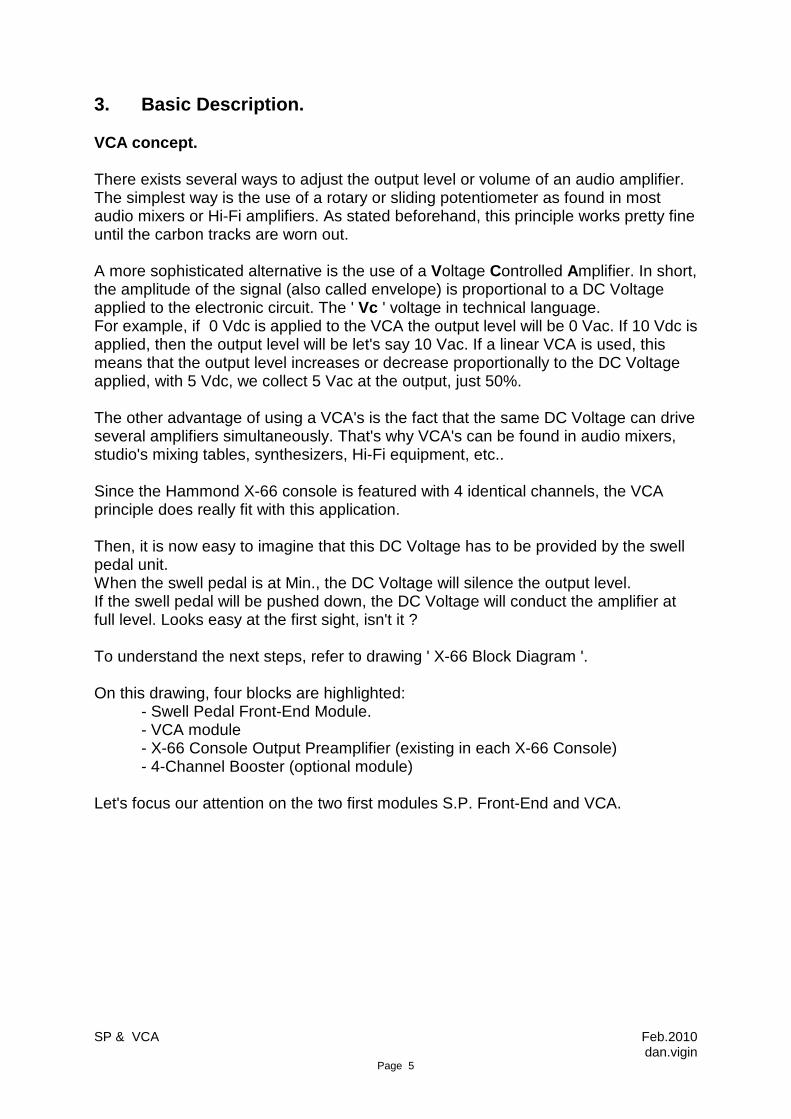
3. Basic Description. VCA concept. There exists several ways to adjust the output level or volume of an audio amplifier. The simplest way is the use of a rotary or sliding potentiometer as found in most audio mixers or Hi-Fi amplifiers. As stated beforehand, this principle works pretty fine until the carbon tracks are worn out. A more sophisticated alternative is the use of a Voltage Controlled Amplifier. In short, the amplitude of the signal (also called envelope) is proportional to a DC Voltage applied to the electronic circuit. The ' Vc ' voltage in technical language. For example, if 0 Vdc is applied to the VCA the output level will be 0 Vac. If 10 Vdc is applied, then the output level will be let's say 10 Vac. If a linear VCA is used, this means that the output level increases or decrease proportionally to the DC Voltage applied, with 5 Vdc, we collect 5 Vac at the output, just 50%. The other advantage of using a VCA's is the fact that the same DC Voltage can drive several amplifiers simultaneously. That's why VCA's can be found in audio mixers, studio's mixing tables, synthesizers, Hi-Fi equipment, etc.. Since the Hammond X-66 console is featured with 4 identical channels, the VCA principle does really fit with this application. Then, it is now easy to imagine that this DC Voltage has to be provided by the swell pedal unit. When the swell pedal is at Min., the DC Voltage will silence the output level. If the swell pedal will be pushed down, the DC Voltage will conduct the amplifier at full level. Looks easy at the first sight, isn't it ? To understand the next steps, refer to drawing ' X-66 Block Diagram '. On this drawing, four blocks are highlighted: - Swell Pedal Front-End Module. - VCA module - X-66 Console Output Preamplifier (existing in each X-66 Console) - 4-Channel Booster (optional module) Let's focus our attention on the two first modules S.P. Front-End and VCA.
SP
& V
CA
Feb.2010
dan.vigin P
age 6
White LED
Phototransistor
Variable shutter
Swell Pedal
Pivot
Front-End circuit
Tabs
Drawbar ‘A’
Drawbar ‘B’
Reverb
LDR
LDR
LDR
LDR
7-Pins socketsfor TC-1277
Vc output for ext. multi-channel VCA module
Vc
Vc
Vc
Vc
Vc
Vc
Existing X-66 Console Output Preamplifier
VCA (Voltage Controlled Amplifier)
4-CH Booster(optional)
Drawbar ‘B’
Draw.‘A’
Draw.‘B’
Tabs
Reverb
Draw.‘A’
Reverb
Tabs
Draw.‘B’
Swell Pedal Front-End Module
+24Vdc
-24Vdc
GND
OUT ‘A’
OUT ‘B’
OUT ‘Rev.’
OUT ‘Tabs’
To external Audio Mixer
+24Vdc
GND
Draw.‘B’
Tabs
Reverb
Draw.‘A’
X-66 VCA Block-DiagramFile: Block_Dia_01.vsd
Date : 03/02/2010 Issued by : Dan.Vigin
+12Vdc
GND
Light beam
SP & VCA Feb.2010 dan.vigin
Page 7
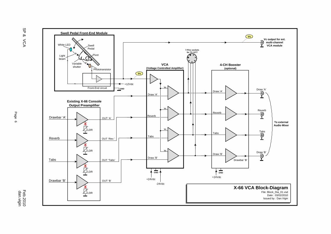
4. Swell Pedal Front-End Module. As announced, the purpose of VCA is to get rid of the LDR's and bulb lamp and replace them by new optical components. Later on, this module has to provide the adequate DC Voltage (Vc) in function of the angle of the swell pedal. If the above statement looks rather simple at the first sight, it is not because it involves mechanical modifications to accommodate those new optical devices and the addition of an electronic circuit which role is to provide the required Vc in order to drive later on the four VCA amplifiers. Mechanical aspect : White LED and Phototransistor. The shutter assembly has to be dismounted from the swell pedal unit. The bulb lamp socket is removed as well as the support fixing the original LDR's. The bulb lamp socket has to be replaced by the white LED (left side). Inevitably some mechanical adaptations are required in such way that the LED is beamed correctly. Similarly, on the right end, the Phototransistor (right side) is encased in the shutter assembly. Be sure to occult the rear side of this Phototransistor. Those devices are extremely sensitive to light and any back light will affect the normal operation.
The original filter has to be removed and replaced by a more transparent one. Transparent plastic material recuperated from blister pack slightly frosted with sand paper will do the job. That was it for the easiest mechanical part.
SP & VCA Feb.2010 dan.vigin
Page 8
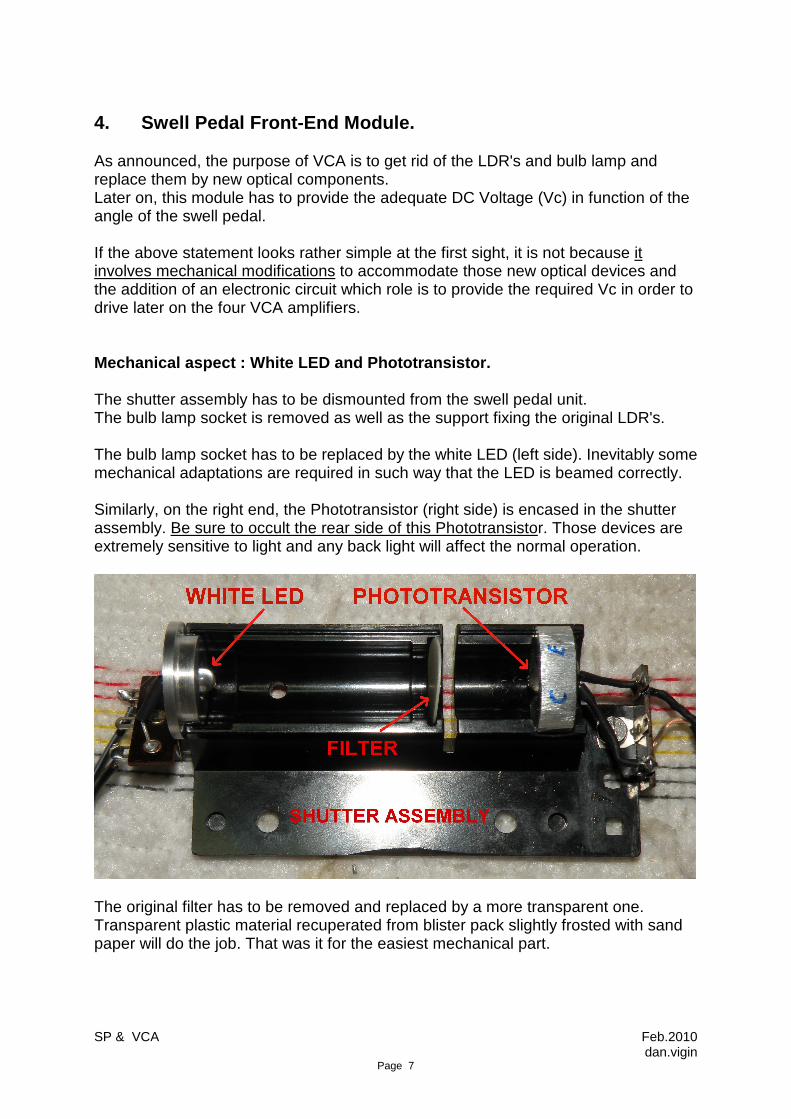
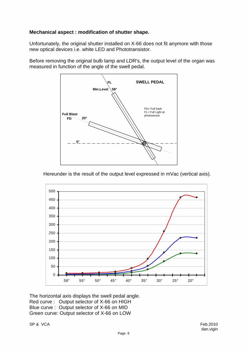
Mechanical aspect : modification of shutter shape. Unfortunately, the original shutter installed on X-66 does not fit anymore with those new optical devices i.e. white LED and Phototransistor. Before removing the original bulb lamp and LDR's, the output level of the organ was measured in function of the angle of the swell pedal.
Hereunder is the result of the output level expressed in mVac (vertical axis).
0
50
100
150
200
250
300
350
400
450
500
58° 55° 50° 45° 40° 35° 30° 25° 20°
The horizontal axis displays the swell pedal angle. Red curve : Output selector of X-66 on HIGH Blue curve : Output selector of X-66 on MID Green curve: Output selector of X-66 on LOW
0°
20°
58°Min.Level
Full Blast
FL
FD
FD= Full DarkFL= Full Light at photosensor
SWELL PEDAL
SP & VCA Feb.2010 dan.vigin
Page 9
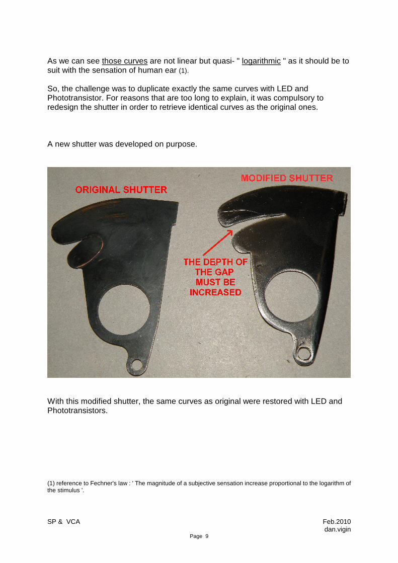
As we can see those curves are not linear but quasi- " logarithmic " as it should be to suit with the sensation of human ear (1). So, the challenge was to duplicate exactly the same curves with LED and Phototransistor. For reasons that are too long to explain, it was compulsory to redesign the shutter in order to retrieve identical curves as the original ones. A new shutter was developed on purpose.
With this modified shutter, the same curves as original were restored with LED and Phototransistors. (1) reference to Fechner's law : ' The magnitude of a subjective sensation increase proportional to the logarithm of the stimulus '.
SP & VCA Feb.2010 dan.vigin
Page 10
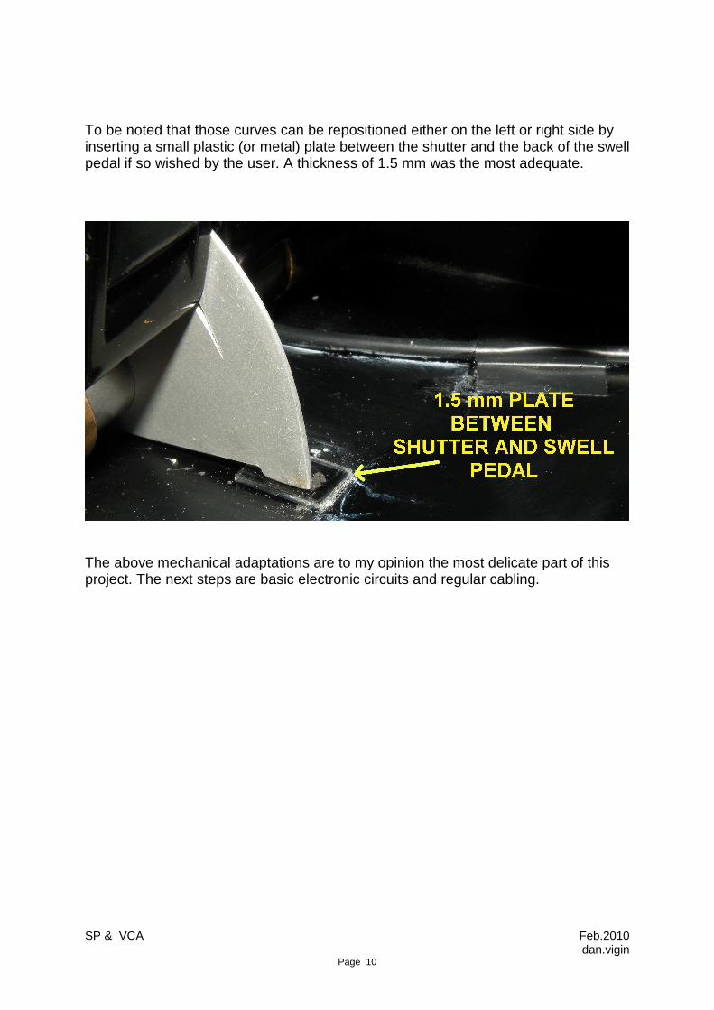
To be noted that those curves can be repositioned either on the left or right side by inserting a small plastic (or metal) plate between the shutter and the back of the swell pedal if so wished by the user. A thickness of 1.5 mm was the most adequate.
The above mechanical adaptations are to my opinion the most delicate part of this project. The next steps are basic electronic circuits and regular cabling.
SP & VCA Feb.2010 dan.vigin
Page 11
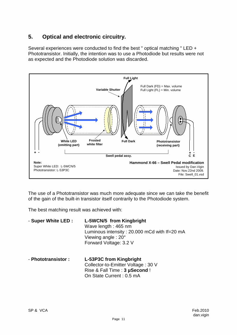
5. Optical and electronic circuitry. Several experiences were conducted to find the best " optical matching " LED + Phototransistor. Initially, the intention was to use a Photodiode but results were not as expected and the Photodiode solution was discarded.
White LED (emitting part)
Phototransistor(receiving part)
Variable Shutter
Full Dark
Swell pedal assy.
Full Light
Frosted white filter
+ +- -C E
Full Dark (FD) = Max. volumeFull Light (FL) = Min. volume
Note: Super White LED: L-5WCN/5Phototransistor: L-53P3C
Hammond X-66 – Swell Pedal modificationIssued by Dan.Vigin
Date: Nov.22nd 2009.File: Swell_01.vsd
The use of a Phototransistor was much more adequate since we can take the benefit of the gain of the built-in transistor itself contrarily to the Photodiode system. The best matching result was achieved with: - Super White LED : L-5WCN/5 from Kingbright Wave length : 465 nm Luminous intensity : 20.000 mCd with If=20 mA Viewing angle : 20° Forward Voltage: 3.2 V - Phototransistor : L-53P3C from Kingbright Collector-to-Emitter Voltage : 30 V Rise & Fall Time : 3 µSecond ! On State Current : 0.5 mA
SP & VCA Feb.2010 dan.vigin
Page 12
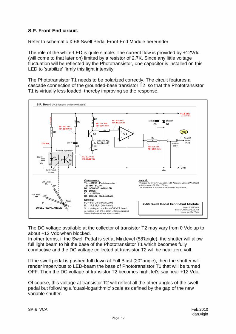
S.P. Front-End circuit. Refer to schematic X-66 Swell Pedal Front-End Module hereunder. The role of the white-LED is quite simple. The current flow is provided by +12Vdc (will come to that later on) limited by a resistor of 2.7K. Since any little voltage fluctuation will be reflected by the Phototransistor, one capacitor is installed on this LED to 'stabilize' firmly this light intensity. The Phototransistor T1 needs to be polarized correctly. The circuit features a cascade connection of the grounded-base transistor T2 so that the Phototransistor T1 is virtually less loaded, thereby improving so the response.
4
8
-
2.7
K 10K
68 K
10K
33K 1N4007
100 nF1 K
3
2
1
100 nF
100 nF
IC-1
T1
T2
D1
D2
LIN
+ 12 Vdc
GND
To VCA Board (IC2)Shielded
cable
Components.T1 : L-53P3C - PhototransistorT2 : NPN - BC107D1 : L-5WCN/5 - White LEDD2 : 1N4007IC1 : ½ LM358NR4 : 10K LIN - Min.Level Adj.
I=3.
4 m
A
FL: 0.17 VdcFD: 11.39 Vdc
FL: 2.93 VdcFD: 11.88 Vdc
FL: 2.25 VdcFD: 11.66 Vdc
FL: 2.25 VdcFD: 11.66 Vdc
FL: 2.25 VdcFD: 10.66 Vdc
2.74 Vdc
R1
R2R3
R4
R5
C1
C2
C3
Note #2:R4: adjust the level in FL position ( 58°). Adequat e values of Vc should be in the range of 2.00 to 2.50 Vdc. This adjustment of Min.level is left to user’s appreciation.
S.P. Board (PCB located under swell pedal)
Swell Pedal Shutter
20°Full Blast
FD
58°
Min.LevelFL
0°
SWELL PEDAL ANGLE
Pivot
Min.Level Adj. (see Note #2)
+
E
A
K
C
Shutter Assembly
(11.93Vdc)
X-66 Swell Pedal Front-End ModuleDate : 21/01/2010
File: SP_Front_End_01.vsdIssued by : Dan.Vigin
Note #1:FD = Full Dark (Max.Level)FL = Full Light (Min.Level)Vc = Voltage control to 4-CH VCA board All resistors ¼ W - 5% or better - otherwise specifiedSubject to change without advance notice
Vc
The DC voltage available at the collector of transistor T2 may vary from 0 Vdc up to about +12 Vdc when blocked. In other terms, if the Swell Pedal is set at Min.level (58°angle), the shutter will allow full light beam to hit the base of the Phototransistor T1 which becomes fully conductive and the DC voltage collected at transistor T2 will be near zero volt. If the swell pedal is pushed full down at Full Blast (20° angle), then the shutter will render impervious to LED-beam the base of Phototransistor T1 that will be turned OFF. Then the DC voltage at transistor T2 becomes high, let's say near +12 Vdc. Of course, this voltage at transistor T2 will reflect all the other angles of the swell pedal but following a 'quasi-logarithmic' scale as defined by the gap of the new variable shutter.

SP & VCA Feb.2010 dan.vigin
Page 13
The DC voltage available at transistor T2 is driving the operational amplifier IC-1 mounted in voltage follower/buffer configuration. This means that the gain of this stage will be " x1 " but the output impedance will be low to feed later on the VCA module. One last point is the variable potentiometer R4 on the schematic diagram. The role of this R4 is quite relevant and does merit some attention. When the swell pedal is set at Min.level (58° angle ), generally the output level of the organ is never set to 'zero' output. I mean 'no sound' can be heard. Even at Min.level, some little output level should be audible. The role of this potentiometer R4 is precisely to allow adjustment of this audio output with the swell pedal at Min. level (58°) to the lev el as wished by the user. To my opinion, the correct setting should be in the range of 2.0 Vdc to 2.5 Vdc at transistor T2 (adjusted to 2.25 Vdc in my case).
With this front-end circuit, the needed voltage " Vc " (Voltage Control) is now ready to be connected to the VCA module. Twin shielded cable is recommended: - one cable to carry the +12 Vdc from VCA board. - one cable to feed the VCA board with the voltage control ' Vc '. Note: as shown, the S.P.Front-End board has been installed on a metal plate (grounded) under the swell pedal assembly.

SP & VCA Feb.2010 dan.vigin
Page 14
6. VCA Module. Back to the Block-Diagram, the Front-End module has been covered. Now the next block involved is the VCA module (Voltage Controlled Amplifier). Since the X-66 console is featured with four channels (Draw 'A', Draw 'B', 'Tabs' and 'Reverb') evidently, the VCA module will be composed of four identical and discrete channels. Only one channel will be described hereafter while two channels are displayed on the drawing. Refer to drawing ' 4-CH VCA module for X-66 Swell Pedal ' on the next page. Several VCA circuits were experimented on the bench and the best result at least for that X-66 application was the use of the IC ' LM13700 ' ( Dual Operational Transconductance Amplifier with Linearizing Diodes and Buffers produced by National Semiconductor ). Refer to Data Sheets LM13700. VCA simplified Circuit Description. When analyzing the different VCA circuits, generally two versions are proposed: - the LOG (for logarithmic) version that provides a logarithmic output level in function of the Vc voltage. - the LINEAR version providing a linear output level proportional to Vc voltage. We have seen in the previous section S.P.Front-End that the 'logarithmic' curve is already generated by the variable shutter of the swell pedal. So only the LINEAR version will be taken into consideration in this particular case. The Voltage Control Vc issued from the S.P.Front-End board is connected to IC-2 (#5 of LM358) simply mounted in voltage follower/buffer configuration. The output of IC-2 (#7) is driving IC-3D (#13) via 100K resistor. The summed control voltage at the output of IC-3D (#14) is sent to IC-3C (#9) for additional amplification and later on to IC-4A (#1) via the 30K resistor. The current generated by IC-3C (#8) through the 30K resistor is applied to the 'Amp Bias In' of IC-4A (#1) controlling so the current through this device and the subsequent amplitude of the resulting voltage generated across the 4.7K resistor connected to the -12 Vdc. The built-in buffer of IC-4A is used to drive the output level. The 100K offset adjustment trimpot linked to IC-3D (#13) is needed to null the gain for whatever voltage used to drive the VCA. The 420 Ω resistor connected to IC-4A (#3) will adjust the input level at the non-inverting input of IC-4A. This adjustment is important and was set to 500 mVac input voltage @ 1KHz (sinus). In this application, the correct value is 420 Ω (combination of 270 Ω + 150 Ω in series). This adjustment in conjunction with the 100K offset trimpot requires the greatest attention.

SP
& V
CA
Feb.2010
dan.vigin P
age 15
-IC-3D
+
Vc
-IC-3C+
2K
100K
LIN
100K
100K
+ 12 Vdc
- 12 Vdc
2K
2K
100K470
+ 12 Vdc
- 12 Vdc
+ 12 Vdc
- 12 Vdc
30K 20K - 12 Vdc
IC-4A
+
-
+ 12 Vdc
Signal Output
GND
1K
50K500K
GND
Signal Input
+
-
10K
100K
4.7K
+ 12 Vdc
100K
420 O
+ 12 Vdc
611
- 12 Vdc
100K
2
4
31
5 7
8
13
12
14
9
10 8
4
11
GNDIC-2
-IC-3A+
-IC-3B+
2K
100K
100K
+ 12 Vdc
- 12 Vdc
2K
2K
100K470
+ 12 Vdc
- 12 Vdc
+ 12 Vdc
- 12 Vdc
30K 20K - 12 Vdc
IC-4B
+
-
+ 12 Vdc
Signal Output
1K
50K500K
GND
Signal Input
4.7K
+ 12 Vdc420
O 10
100K
3
2
16
5 7
4
11
GND
100K
N/C
N/C
14
15
13
16 11
12
9
5
6
7
8
4
LIN
Active Components :IC-2 : LM358NIC-3 : TL084NIC-4 : LM13700
½ LM13700
½ LM13700
TL084
TL084
TL084
TL084
LM358
See Note #1
See Note #1
Notes:1 – 270 O + 150 O in series2 - All resistors are ¼ W – 5% or better3 - Gain : x 1 – Linear VCA ( signal output is directly proportional to Voltage Control applied Vc).4 – Signal Input levels : from 5mVac to 2.5 Vac @ 1 KHz5 - Values of components are selected to match only with Hammond X-66 output levels.6 – Decoupling caps of 100 nF (B+ & B-) are not shown.
4-CH. VCA Module for X66 Swell Pedal Date : 22/01/2010
File: Linear_VCA_01.vsdIssued by : Dan Vigin
Voltage Control input
TABS Signal
DRAWBARS ‘A’ Signal
100K
100K
100K
To IC-5A & IC-5D
ONLY TWO CHANNELS OUT OF FOUR ARE SHOWN ON THIS SCH EMATIC DIAGRAM.
SP & VCA Feb.2010 dan.vigin
Page 16
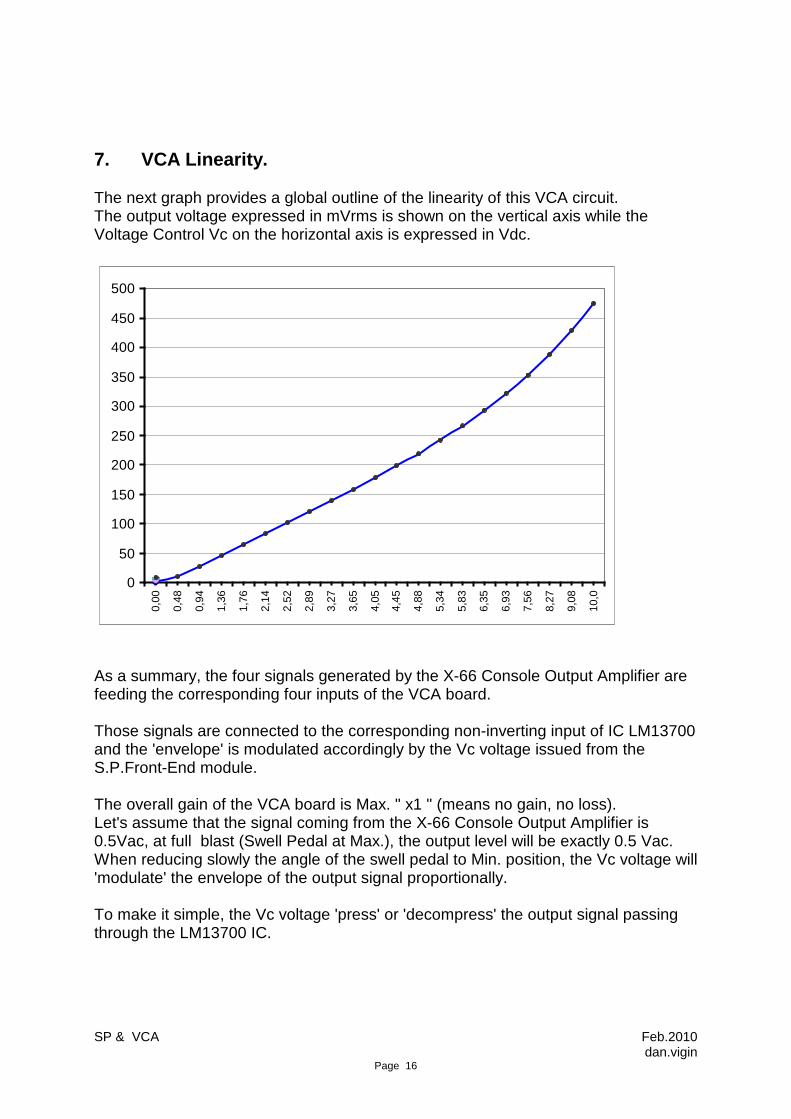
7. VCA Linearity. The next graph provides a global outline of the linearity of this VCA circuit. The output voltage expressed in mVrms is shown on the vertical axis while the Voltage Control Vc on the horizontal axis is expressed in Vdc.
0
50
100
150
200
250
300
350
400
450
500
0,00
0,48
0,94
1,36
1,76
2,14
2,52
2,89
3,27
3,65
4,05
4,45
4,88
5,34
5,83
6,35
6,93
7,56
8,27
9,08
10,0
As a summary, the four signals generated by the X-66 Console Output Amplifier are feeding the corresponding four inputs of the VCA board. Those signals are connected to the corresponding non-inverting input of IC LM13700 and the 'envelope' is modulated accordingly by the Vc voltage issued from the S.P.Front-End module. The overall gain of the VCA board is Max. " x1 " (means no gain, no loss). Let's assume that the signal coming from the X-66 Console Output Amplifier is 0.5Vac, at full blast (Swell Pedal at Max.), the output level will be exactly 0.5 Vac. When reducing slowly the angle of the swell pedal to Min. position, the Vc voltage will 'modulate' the envelope of the output signal proportionally. To make it simple, the Vc voltage 'press' or 'decompress' the output signal passing through the LM13700 IC.

SP & VCA Feb.2010 dan.vigin
Page 17
8. Powering VCA board. To be noted that this 4CH-VCA has to be powered by + 12 Vdc and -12 Vdc. This is achieved by using two voltage regulators LM7812 and LM7912 mounted on the VCA board. The +12Vdc needed to feed the S.P.Front-End module is picked up from this VCA board. Both input DC voltages (+/- 24 Vdc) are coming from the X-66 PSU block. Overall consumption is +38mAdc (S.P.Front-End included) for B+ and -35 mAdc for B-. Refer also to X-66 VCA Block-Diagram and Wiring for details in PSU part.
P1TR1
+
+
-
91O
/10W
10O
/5W
+
-
+
-
+
-
220 Vac
GRN
GRN
GRN/WHT
BLU
BLU
BLU/WHT
YEL
YEL
BRN/WHT
RED
RED
CH-2
R1
R2 C4
C3
D3
D4
C5
+ 34.1 Vdc
+ 28 Vdc
+ 3.0 Vdc
2200 µF50 V
1000 µF16 V
2200 µF50 V
2x 1N4007- 37.6 Vdc
1
5
2A
5A
GRY
YEL
F
See Fig.5-8 Schematic Diagram Power Supply – Page 5-9 – for details
Circuit to be added in existing Power Supply unit.
7924-24Vdc REG.
7824+24Vdc REG.
150 µF40 V
150 µF40 V -
-
+
100 nF100V
100 nF100V
- 24 Vdc
+ 24 Vdc1
1
2
3
32
GND
GND
GND
GND
GND
X66 POWER SUPPLY UNIT
IN
IN OUT
OUT
G
G

SP & VCA Feb.2010 dan.vigin
Page 18
9. VCA Installation in X-66 Console.
The picture herabove exhibits the VCA board installed in the X-66 console nearby the Console Output Amplifier. All cables are shielded. Short description:
- the first IC on the bottom is IC-2 (LM358) assuring the distribution of the Vc voltage to the four VCA circuits. - Nearby this IC are located the four 100 K trimpots (25 turns). - The two other IC's are basic opamps TL084 ( 4 opamps per IC ) - The two IC's on the upper side are the LM13700 ( 2 amplifiers per IC ). - On the top, both regulators LM7812 and LM7912 providing +/- 12Vdc.

SP & VCA Feb.2010 dan.vigin
Page 19
In this particular X-66, this VCA board is installed on top of a 4CH-booster board. Both units are surrounded by a metal shield enclosure to minimize background noise, interferences and the like. See picture hereunder.

SP & VCA Feb.2010 dan.vigin
Page 20
10. X-66 Block-Diagram & Final Wiring. The next drawing exhibits the concerned 'blocks' and the related cabling between each others. This drawing being in A3 format can be found in the annexes " X-66 VCA Block-Diagram & Wiring ". X-66 Power Supply. Some modifications (easy to realize) have to be implemented in the X-66 Power Supply unit (see 'circuit added' in grey background) to feed the VCA board with +/- 24 Vdc. VCA Module. The three output signals from the X-66 Console Output Amplifier are routed directly to the corresponding inputs of the VCA Module. The Reverb channel signal is coming from the Recovery Reverb Preamp and connected to the fourth input of VCA. The four output of VCA board are driving directly the 7-pin socket to TC-1277 cabinets. Those four output signals may also be connected to an external audio mixer or an optional 4-CH Booster. External Multi-Channel VCA Module. For those who want to take benefit of the X-66 swell pedal to drive their external MIDI sound modules, expanders, synth's, etc.. it is rather simple to collect the voltage Control 'Vc' from the S.P.Front-End module to command later on an external Multi-Channel VCA module. This external Multi-Channel is under development and will be available very soon. Basically, this unit will be composed of two (or three) 4-Ch VCA boards (same as described here-above) but will be featured will switchable stereo input faders. Of course, this unit will be equipped with its own PSU separated from the X-66 Console.
SP & VCA Feb.2010 dan.vigin
Page 21
11. Conclusions This S.P.Front-End and 4-CH VCA modules have been installed on my X-66 and needless to repeat that the attack response is much better by comparison with the original LDR system. The second reason to implement VCA is to drive the external MIDI devices with the same voltage control 'Vc' through the X-66 swell pedal. This Multi-Channel VCA will be the object of another project coming soon. The other 'plus-points' are the1 possibilities to adapt the levels at your own discretion, this means :
- we have seen that the Min. level can be adjusted by any user with Trimpot R4 of the S.P. Front-End module. - the horizontal position of the curves depicted on the graph of Page 8 can be adjusted to some extends by adding (or removing) spacers between the swell pedal and the variable shutter. - other adjustments on VCA board allow adaptation of input/output levels as wished.
Hope having been of some help, Dan. Vigin