hand-based verification and identification using palm–finger
TRANSCRIPT

Author's personal copy
Hand-based verification and identification using palm–fingersegmentation and fusion
Gholamreza Amayeh, George Bebis *, Ali Erol, Mircea NicolescuComputer Vision Laboratory, University of Nevada, Reno 89557, United States
a r t i c l e i n f o
Article history:Received 30 January 2008Accepted 28 November 2008Available online 24 December 2008
Keywords:BiometricsHand-based verificationHand-based recognitionFusionPCAMajority votingSVMs
a b s t r a c t
Hand-based verification/identification represent a key biometric technology with a wide range of poten-tial applications both in industry and government. Traditionally, hand-based verification and identifica-tion systems exploit information from the whole hand for authentication or recognition purposes. Toaccount for hand and finger motion, guidance pegs are used to fix the position and orientation of thehand. In this paper, we propose a component-based approach to hand-based verification and identifica-tion which improves both accuracy and robustness as well as ease of use due to avoiding pegs. Ourapproach accounts for hand and finger motion by decomposing the hand silhouette in different regionscorresponding to the back of the palm and the fingers. To improve accuracy and robustness, verification/recognition is performed by fusing information from different parts of the hand. The proposed approachoperates on 2D images acquired by placing the hand on a flat lighting table and does not require usingguidance pegs or extracting any landmark points on the hand. To decompose the silhouette of the handin different regions, we have devised a robust methodology based on an iterative morphological filteringscheme. To capture the geometry of the back of the palm and the fingers, we employ region descriptorsbased on high-order Zernike moments which are computed using an efficient methodology. The proposedapproach has been evaluated both for verification and recognition purposes on a database of 101 subjectswith 10 images per subject, illustrating high accuracy and robustness. Comparisons with relatedapproaches involving the use of the whole hand or different parts of the hand illustrate the superiorityof the proposed approach. Qualitative and quantitative comparisons with state-of-the-art approachesindicate that the proposed approach has comparable or better accuracy.
� 2008 Elsevier Inc. All rights reserved.
1. Introduction
Recently, there has been increased interest in developing bio-metrics-based verification and identification systems which hasled to intensive research in fingerprint, face, hand, ear, and irisauthentication and recognition. Each biometric has its ownstrength and weakness depending on the specific application andits requirements. Hand-based biometrics is among the oldest livebiometrics-based authentication modalities. The existence of sev-eral hand-based authentication commercial systems and patentsindicate the effectiveness of this type of biometric. Althoughhand-based live authentication has a long history and a consider-able market share [1], most studies addressing enhancements ofthis technology are rather recent [2]. Increases in computing powerand advances in computer vision and pattern recognition are ex-pected to enable the implementation of more accurate, robust,and easier to use systems. Removal of pegs, to improve conve-
nience, and use of more powerful features to represent the shapeof the hand represent promising research directions in this area.
The geometry of the hand contains relatively invariant featuresof an individual, however, geometric features of the hand (e.g., fin-ger length/width, area/size of the palm) are not as distinctive asfingerprint or iris features. Therefore, hand-based biometric sys-tems have been employed mostly in small-scale person authenti-cation applications. In this study, we demonstrate the applicationof hand-based biometrics for identification purposes as well. Themain difference between verification and identification is that inthe case of verification, an unknown subject is compared againsta specific subject in the database to verify his/her identity (i.e.,‘‘Am I who I claim”). In the case of identification, an unknown sub-ject is compared against all the subjects in the database to estab-lish his/her identity (i.e., ‘‘Who am I?”). Therefore, identificationcan be thought as verifying an unknown subject against all sub-jects in the database. As a result, identification is more time con-suming and prone to errors.
There are several reasons for developing hand-based verifica-tion/identification systems. First, the shape of the hand can beeasily captured in a relatively user friendly manner by using
1077-3142/$ - see front matter � 2008 Elsevier Inc. All rights reserved.doi:10.1016/j.cviu.2008.11.007
* Corresponding author. Fax: +1 775 784 1877.E-mail addresses: [email protected] (G. Amayeh), [email protected] (G.
Bebis), [email protected] (A. Erol), [email protected] (M. Nicolescu).
Computer Vision and Image Understanding 113 (2009) 477–501
Contents lists available at ScienceDirect
Computer Vision and Image Understanding
journal homepage: www.elsevier .com/locate /cviu
Author's personal copy
conventional CCD cameras. Second, this technology is more accept-able by the public in daily life mainly because it lacks a close con-nection to forensic applications. Finally, there has been someinterest lately in fusing different biometrics to increase systemperformance [3,4]. The ease of use and acceptability of hand-basedbiometrics make hand shape a good candidate in these heteroge-neous systems.
In this paper, we propose a novel, peg-free approach to hand-based verification and identification which does not requireextracting any landmark points on the hand and it is not sensitiveto hand and finger motion. The proposed approach operates on 2Dhand images acquired by placing the hand on a planar lighting ta-ble without any guidance pegs. There are several important ideasbehind the proposed approach. First, to deal with the issue of handand finger motion, we decompose the silhouette of the hand in dif-ferent regions corresponding to the back of the palm and fingers.This is performed using a robust methodology based on an iterativemorphological filtering scheme. To avoid touching fingers and sim-plify segmentation, subjects are required to stretch their handprior to placing it on the lighting table. No other restrictions areimposed on the subjects. Second, in contrast to traditional ap-proaches that represent the shape of the explicitly using hand-crafted geometrical measurements, we represent the geometry ofeach part of the hand implicitly using high-order Zernike moments[5]. Finally, to improve verification/identification accuracy androbustness, we fuse information from different parts of the hand.It is worth mentioning that the use of high-order moments is notpractical for many applications due to their noise sensitivity. How-ever, this is not an issue in the context of our application since weuse a robust image acquisition process which provides very highquality hand images as shown in Section 3.
Moments have been used before in a wide range of applicationsin image analysis, and object recognition [6]. In the area of biomet-rics, preliminary results have been reported using various types ofmoments (e.g., geometric, Zernike, pseudo-Zernike, and Legendremoments) for palmprint verification [7,8]. Zernike moments arequite attractive for representing the geometry of the hand due tohaving minimal redundancy (i.e., employ orthogonal basis func-tions [9]), providing invariance to translation, rotation, and scale,and demonstrating robustness to noise [6]. In most applications,the use of Zernike moments has been limited to low-orders onlyor small low-resolution images due to high computational require-ments and lack of accuracy due to numerical errors. Capturing theshape of the hand in sufficient detail, however, would require com-puting moments of rather high-orders. Although there have beenseveral efforts to reduce computational complexity by employingquantized polar coordinate systems, such transformations havean effect on accuracy. In this study, we employ an improved algo-rithm, proposed in one of our earlier studies [10], which can speedup the computation of high-order Zernike moments without sacri-ficing accuracy. To keep computational complexity low, we avoidredundant computations by detecting common terms and usinglook-up tables. To preserve accuracy, we avoid any coordinatetransformations and employ arbitrary precision arithmetic.
Fusing information from different biometric modalities (i.e.,face, fingerprint, hand) has received considerable attention lately,however, fusing information from different parts of the same bio-metric has been considered to a lesser extent. For example, Rossand Govindarajan [11] have reported a feature-level fusion schemewhich combines hand and face features. Kumar and Zhang [12]have investigated feature selection of hand shape and palm printfeatures. Cheung et al. [13] have proposed a two-level fusion strat-egy for multimodal biometric verification. Jiang and Su [14] haveproposed fusing faces and fingerprints to improve verificationaccuracy. Our approach is mostly related to component-based ap-proaches in object detection and recognition [15,16], face detec-
tion/recognition [17], and person detection [18]. The key ideabehind them is representing objects in terms of their parts andgeometrical relationships. Among them, the most relevant ap-proach to ours is the face recognition approach reported in [17].In that study, information from different parts of the face was fusedat the feature-level using Support Vector Machines (SVMs) [19].Here, we report results using several different fusion strategiesincluding feature-level, score-level and decision-level. Earlier ver-sions of our work have appeared in [20–22].
The rest of the paper is organized as follows: Section 2 containsa review of hand-based verification and identification systems. Anoverview of the proposed approach is presented in Section 3. Sec-tion 4.2 reviews Zernike moments and presents an efficient algo-rithm for computing high-order Zernike moments. Section 5presents our methodology for separating the hand from the armand decomposing the hand silhouette in different parts corre-sponding to the back of the palm and the fingers. Representingthe geometry of the shape of the palm and the fingers using Zer-nike moments is discussed in Section 6. Section 7 presents the fu-sion strategies investigated in this study. Experimental results andcomparisons are presented in Section 8. Finally, Section 9 providesour conclusions and directions for future work.
2. Review of hand-based biometrics
The majority of hand-based biometric systems employ geomet-ric measurements and are based on research limited to consider-ably old patents and commercial products [23]. In these systems,users are asked to place their hand on a flat surface and align it,with the help of some guidance pegs. The alignment operation sim-plifies feature extraction and allows for high processing speeds. Amirror is usually used to obtain a side view of the hand using a sin-gle camera. In most cases, a few hand-crafted geometric features(e.g., length, width and height of the fingers, thickness of the hand,aspect ratio of fingers and palm, etc.) are extracted, making it pos-sible to construct a small template (i.e., 9 bytes in some commer-cial systems).
Removal of pegs, to improve convenience, and use of more pow-erful feature extraction techniques to capture the shape of thehand more accurately represent promising research directions inthis area. Several studies have reported that peg-based alignmentis not very satisfactory and represents in some cases a considerablesource of failure [24,25]. Although peg removal provides a solutionto reduce user inconvenience, it also raises more challengingresearch issues due to the increase in intra-class variance. Never-theless, most recent studies have concentrated on the design ofpeg-free systems.
Extracting extremities of the hand contour, such as finger val-leys and finger tips, is usually the first processing step in these sys-tems. In peg-free systems, fingers are not guaranteed to be at thesame position and orientation at different acquisition times; there-fore they need to be segmented and identified in the input images.Analysis of the silhouette contour to locate fingertips and palm–finger intersections, which basically corresponds to curvature localmaxima, provides an effective solution to the segmentation prob-lem [26,27]. Once the fingers have been segmented, geometric fea-tures such as finger length and width can be measured atpredefined points along the finger axes [4,27–29].
Using geometric features helps to reduce storage requirementsbut can not represent hand shape in detail. Moreover, accuratelocalization of various landmark points on the fingers is not astraightforward task. Some studies have introduced new featurescapturing the full finger shape. Jain and Duta [30] have used the sil-houette contour of the fingers and an iterative closest point (ICP)alignment algorithm to compute a shape distance which is usedas a measure of similarity. Ma et al. [31] have followed a similar
478 G. Amayeh et al. / Computer Vision and Image Understanding 113 (2009) 477–501
Author's personal copy
approach using B-Spline curves. Xioang et. al. [26] introduced asemi-geometric approach by extracting geometric features afteraligning the fingers which are represented using ellipses. Kumaret. al [32] used palmprint and hand geometric features where theextremities of the hand contour were used to measure fingerlength and palm width. Recently, Yoruk et. al. [33] introduced amore accurate and detailed representation of the hand using theHausdorff distance of the hand contour, and Independent Compo-nent Analysis (ICA)[19]. Their approach requires registering the sil-houettes of the hand images using the locations of fingertips andvalleys. This study is among a few studies where hand-based bio-metrics have been demonstrated both for verification and recogni-tion purposes.
A marginally different feature extraction approach, which in-volves reconstructing the 3D surface of the hand, was proposedin [34]. Using a range sensor to reconstruct the dorsal part of thehand, local shape index values of the fingers were used as featuresin matching. In a related study, Lay [35] projected a parallel gratingonto the dorsal part of the hand to extract features that indirectlycapture 3D shape information. Use of multiple enrollment tem-plates is an effective method to improve the recognition accuracyof any biometric system. In the hand-based biometrics domain,using multiple enrollment templates is vital part of any systemmainly due to the lower distinctiveness of hand shape. User-spe-cific statistical models, such Mixtures of Gaussians [36,37], haveshown to improve system accuracy [27,29,36,37].
3. System overview
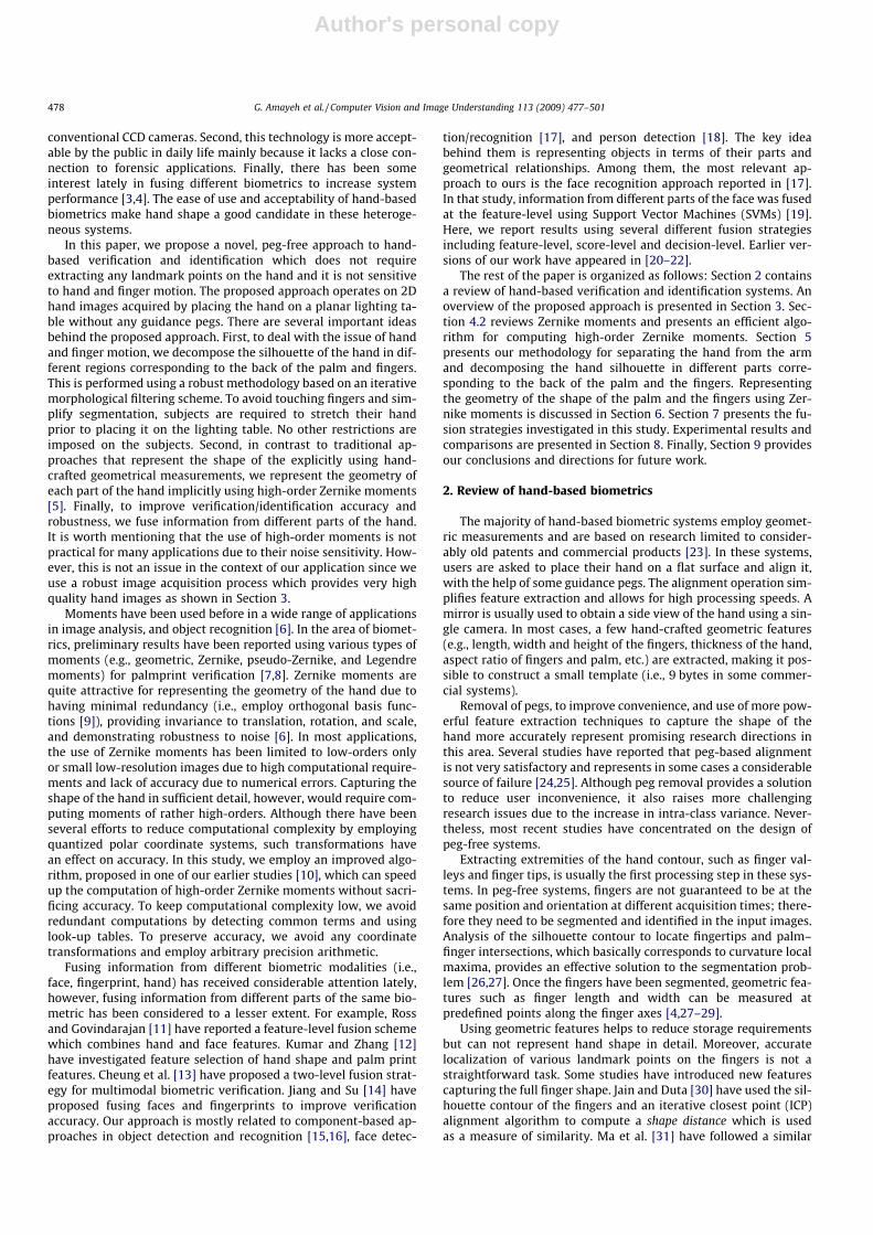
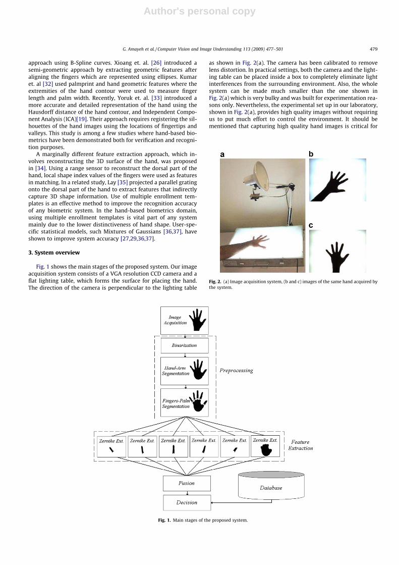
Fig. 1 shows the main stages of the proposed system. Our imageacquisition system consists of a VGA resolution CCD camera and aflat lighting table, which forms the surface for placing the hand.The direction of the camera is perpendicular to the lighting table
as shown in Fig. 2(a). The camera has been calibrated to removelens distortion. In practical settings, both the camera and the light-ing table can be placed inside a box to completely eliminate lightinterferences from the surrounding environment. Also, the wholesystem can be made much smaller than the one shown inFig. 2(a) which is very bulky and was built for experimentation rea-sons only. Nevertheless, the experimental set up in our laboratory,shown in Fig. 2(a), provides high quality images without requiringus to put much effort to control the environment. It should bementioned that capturing high quality hand images is critical for
Fig. 1. Main stages of the proposed system.
Fig. 2. (a) Image acquisition system, (b and c) images of the same hand acquired bythe system.
G. Amayeh et al. / Computer Vision and Image Understanding 113 (2009) 477–501 479

Author's personal copy
our application as it allows us to use high-order Zernike momentswithout worrying about noise sensitivity issues.
When users place their hand on the surface of the lighting ta-ble, an almost binary, shadow and noise free, silhouette of thehand is obtained as shown in Fig. 2(b) and (c). During acquisition,subjects are required to stretch their hand and place it inside arectangular region marked on the surface of the table. This is toavoid touching fingers, ensure the visibility of the whole hand,and avoid perspective distortions. No restrictions were imposedon the orientation of the hand. The image acquired is then bina-rized and goes through the segmentation module. During seg-mentation, the arm is separated from the hand and discardedfrom further processing. Then, the hand is further processed tosegment the palm and the fingers. Feature extraction is per-formed by computing the Zernike moments of each part of thehand separately. The resulting representation is invariant totranslation, rotation and scaling. Verification/identification is per-formed by fusing information from different parts of the hand.We have experimented with different fusion strategies includingfeature-level, score-level, and decision-level fusion. We employmultiple enrollment templates per subject and compute similarityscores using the minimum distance between a query image andthe templates of the subjects.
Next, we present the algorithm adopted in this study for theefficient computation of high-order moments. Then, we describein detail each stage of the proposed system.
4. Efficient computation of high-order zernike moments
4.1. Motivation and issues
The majority of peg-free systems extract a number of landmarkpoints on the hand (e.g., finger joints) and represent hand shape byexplicitly measuring certain geometric features. Alternatively, onecan imagine utilizing more general shape descriptors to provide aricher representation of the shape of the hand, replacing the con-ventional hand-crafted geometric features. In this study, we pro-pose representing the geometry of the hand implicitly usingZernike moments. Zernike moments have the potential to providea more powerful representation of the shape of the hand, however,capturing important shape details for verification/identificationpurposes would require computing high-order moments. Thisbring up the issues of speed and accuracy.
Although there exist some fast algorithms that rely on approx-imate polar coordinate transformations [38–40], they do not yieldsatisfactory results in the context of our application due to lack ofaccuracy. To deal with these issues, we have adopted an efficientalgorithm that keeps computational complexity low without sacri-ficing accuracy. To preserve accuracy, our algorithm avoids anyform of coordinate transformation by using arbitrary precisionarithmetic. To reduce computational complexity, it avoids recom-puting common terms and employs look-up tables.
4.2. Review of zernike moments
Zernike moments are based on a set of complex polynomialsthat form a complete orthogonal set over the interior of the unitcircle [5]. They are defined as the projection of the image on theseorthogonal basis functions. Specifically, the basis functionsVn;mðx; yÞ are given by
Vn;mðx; yÞ ¼ Vn;mðq; hÞ ¼ Rn;mðqÞejmh ð1Þ
where n is a non-negative integer, m is a non-zero integer subject tothe constraints n� jmj is even and jmj < n, q is the length of thevector from origin to ðx; yÞ, h is the angle between the vector q
and the x-axis in a counter clockwise direction, and Rn;mðqÞ is theZernike radial polynomial which is defined as follows:
Rn;mðqÞ ¼Xn
k¼jmj;n�k¼even
ð�1Þn�k
2 nþk2 !
n�k2 ! kþm
2 ! k�m2 !
qk ¼Xn
k¼jmj;n�k¼even
bn;m;kqk ð2Þ
Note that Rn;mðqÞ ¼ Rn;�mðqÞ. The basis functions in Eq. (1) areorthogonal, therefore, satisfying the constraint:
nþ 1p
Z Zx2þy261
Vn;mðx; yÞV�p;qðx; yÞ ¼ dn;pdm;q ð3Þ
where
da;b ¼1 if a ¼ b
0 otherwise
(ð4Þ
The Zernike moment of order n with repetition m for a digitalimage function f ðx; yÞ is given by [41]:
Zn;m ¼nþ 1
pX X
x2þy261
f ðx; yÞV�n;mðx; yÞ ð5Þ
where V�n;mðx; yÞ is the complex conjugate of Vn;mðx; yÞ. To computethe Zernike moments of a given image, the center of mass of the ob-ject is taken to be the origin. The magnitude of the Zernike mo-ments is rotation invariant by its definition (see Eq. (5)). Takingthe center of mass of the object as the origin of the coordinate sys-tem makes them translation invariant as well. Additionally, to pro-vide scale invariance, the object is scaled inside the unit circle.
The function f ðx; yÞ can then be reconstructed by the followingexpression [41]:
~f ðx; yÞ ¼XN
n¼0
Cn;0
2Rn;0ðqÞ þ
XN
n¼1
Xm>0
ðCn;mcosmhþ Sn;msinmhÞRn;mðqÞ
ð6Þ
where N is the maximum order of Zernike moments used, while Cn;m
and Sn;m denote the real and imaginary parts of Zn;m, respectively.
4.3. Computation of high-order zernike moments
A method to improve the speed of Zernike moments computa-tion involves using a quantized polar coordinate system. In [38],Mukundan and Ramakrishnan proposed a recursive algorithm forthe computation of Zernike and Legendre moments using polarcoordinates. In [39], Belkasim et al. introduced a different recursivealgorithm using radial and angular expansions of Zernike orthonor-mal polynomials. For an M �M image, the angles were quantizedto 4M and the radii were quantized to M levels. In a more recentstudy, Gu et al. [40] employed the ‘‘square to circle” transformationof Mukundan and Ramakrishnan [38] and more efficient recursiverelationships to develop an even faster algorithm, however, itsaccuracy was still limited to that of [38] due to the quantizationstep in the coordinate transformation.
A side effect of quantization is that errors are introduced in thecomputation of high-order Zernike moments (see Section 4.4). Inthis work, we have adopted a novel algorithm which avoids usingany quantization, therefore, the computation of the moments is asaccurate as in the traditional approach (i.e., no approximations). Tosave computation time, the improved algorithm finds the termsthat occur repeatedly in various orders and avoids recomputingthem. Additional computations can be saved using a look-up table.To ensure high accuracy, it uses arbitrary precision arithmetic.
Specifically, by substituting Eqs. (2) and (1) in Eq. (5) and re-organizing the terms, the Zernike moments can be computed asfollows:
480 G. Amayeh et al. / Computer Vision and Image Understanding 113 (2009) 477–501

Author's personal copy
Zn;m ¼nþ 1
pX X
x2þy261
Xn
k¼jmjbn;m;kqk
!e�jmhf ðx; yÞ
¼ nþ 1p
Xn
k¼jmjbn;m;k
X Xx2þy261
e�jmhqkf ðx; yÞ
0@
1A
¼ nþ 1p
Xn
k¼jmjbn;m;kvm;k ð7Þ
The terms vm;k, defined in Eq. (7), are common in the computa-tion of moments having the same repetition as shown in Fig. 3 inthe case of repetition m = 0. In general, to compute Zernike mo-ments up to order N, we would need to compute vm;k for each rep-etition. However, computing vm;k only once would be sufficient forcomputing Zernike moments of any order and any repetition bysimply taking linear combinations as shown in Eq. (7). As an exam-ple, Table 1 shows the terms vm;k required to be computed up toorder 10. Moreover, the coefficients bn;m;k (see Eq. (2)) do not de-pend on the input image or the coordinates; therefore, they canbe stored in a small look-up table to save additional computations.
An important issue in the computation of high-order Zernike isthe issue of numerical precision. Depending on the image size andmaximum order, double precision arithmetic does not provide en-ough precision and serious numerical errors can be introduced inthe computation of the moments. This is demonstrated in Table2 which shows the differences between Zernike moments up to or-der 50, computed using double precision and arbitrary precisionarithmetic for a 300� 300 image. As it can be observed, the error
becomes more and more significant with increasing order anddecreasing repetition.
Fig. 4 shows the effect of numerical errors on the orthogonalityof the basis functions. As it can be observed in Fig. 4(a), obtainedusing double precision arithmetic, the orthogonality of the basisfunctions is violated seriously. On the other hand, the orthogonal-ity of the basis functions is preserved using arbitrary precisionarithmetic as shown in Fig. 4(b) (i.e., only one delta peak ispresent).
4.4. Comparisons with other methods
We have compared the accuracy of our algorithm with severalother algorithms [38–40] using the fidelity of reconstruction as acriterion. The test image that we used in our experiments is shownin Fig. 5(top). This is a 64� 64 image and Zernike moments up toorder 40 were utilized for reconstruction. Fig. 5(a–c) show the re-sults using Mukundan’s method [38], Gu’s method [40] and ourmethod, respectively. As it can be observed, the former two algo-rithms give poor reconstructions mainly because of the square tocircle transformation. The effect of the transformation is clearlyvisible in the reconstructed images.
The reconstruction results using Belkasim’s [39] method andZernike moments up to order 60 is shown in Fig. 6(a) while thereconstruction results using our method is shown in Fig. 6(b).We used arbitrary precision arithmetic in the implementation ofBelkasim’s method to make the comparison fair. It can be observedthat Belkasim’s method introduces some distortions at the edgeswhile our method produces smoother edges in general.
To make the differences between the two methods more clear,we have computed reconstruction errors for each method, shownin Table 3, using different orders. The formula use to computethe error is shown below:
er ¼P
x
Pyj~f ðx; yÞ � f ðx; yÞj2P
x
Pyf ðx; yÞ2
ð8Þ
where f ðx; yÞ is the original image and ~f ðx; yÞ is the reconstructedimage (up to order N).
In general, it would be reasonable to expected that the recon-struction error decreases as the order of moments increases. Ourmethod exhibits this behavior, however, Belkasim’s method be-haves quite differently which indicates that the quantization ofthe polar coordinates has a serious effect on the computation ofhigher-order moments.
Table 4 shows the number of multiplications and additions re-quired by each method. We have assumed an image of sizeM �M pixels and Zernike moments up to order N. In the case ofour method, first we need M2N multiplications to computeqkf ðx; yÞ, k ¼ 0;1; . . . ;N. Then, we must compute vm;k ¼P
x
Pye�jmhqkf ðx; yÞ. The number of vm;k required to compute Zer-
nike moments up to order NðevenÞ is N2
N2 þ 1� �
. Since there is noneed for any multiplication when m ¼ 0 and vm;k is a complexnumber, this step requires M2NðN2 þ 1Þ multiplications and2ðM2 � 1Þ N
2 þ 1� �2 additions. For large N and M, the number of mul-
Fig. 3. Common terms in the computation of Zernike moments up to order 10 withzero repetition.
Table 1The terms vm;k required to be computed up to order 10.
Repetition m vm;k
0 v0;0,v0;2,v0;4,v0;6,v0;8,v0;101 v1;1,v1;3,v1;5,v1;7,v1;92 v2;2,v2;4,v2;6,v2;8,v2;103 v3;3,v3;5,v3;7,v3;94 v4;4,v4;6,v4;8,v4;105 v5;5,v5;7,v5;96 v6;6,v6;8,v6;107 v7;7,v7;98 v8;8,v8;109 v9;9
10 v10;10
Table 2Differences between Zernike moments up to order 50, computed using double precision and arbitrary precision arithmetic for a 300� 300 image.
Order, repetition 0 2 4 6 8 10 . . . 40 42 44 46 48 50
42 7.28e�4 6.60e�4 1.91e�4 2.72e�4 1.72e�4 6.54e�6 . . . 1.17e�17 3.82e� 1744 3.50e�3 5.57e�3 1.11e�3 1.18e�3 1.05e�4 1.49 e�4 . . . 1.52e�15 1.30e�17 1.04e�1746 3.97e�1 6.48 e�3 5.25e�3 2.04e�3 2.57e�3 1.07e�3 . . . 2.12e�14 1.48e� 15 9.06e�17 2.60e�1848 1.86e0 6.91e�2 4.39e�2 2.83e�2 1.66 e�2 3.50e�3 . . . 5.23e�14 5.92 e�14 3.11e�16 1.20e�16 3.47e�1850 1.38e1 1.81e0 1.06e�1 9.39e�2 6.92e�2 7.12e�2 . . . 7.52e�12 2.67 e�13 1.60e�14 8.60e�16 4.65e�17 2.17e�18
G. Amayeh et al. / Computer Vision and Image Understanding 113 (2009) 477–501 481

Author's personal copy
tiplications and additions required to compute Zn;m is negligibleaccording to Eq. (7). Asymptotically, our method has comparablecomputational complexity with Belaksim’s method (i.e., OðN2M2Þmultiplications) although Belaksim’s method performs less addi-tions (i.e., OðNM2Þ versus OðN2M2Þ).
5. Component-based hand representation
This stage includes the binarization of the hand image and itssegmentation into different regions corresponding to the arm,hand, palm, and fingers. Our current set up yields very high qualityimages, which are almost free of shadows and noise. As a result,binarization can be performed using a fixed threshold. To separatethe forearm from the hand, first we detect the palm by finding thelargest circle that can be prescribed inside the hand–arm silhou-ette. Then, we take the intersection of the forearm with the circle’sboundary. To separate the fingers from the palm, first we filter outthe fingers using morphological closing [42]. Then, the palm is sub-tracted from the hand silhouette. Specific details are providedbelow.
5.1. Binarization
The hand images can be captured using a grayscale camera;however, we used a color CCD camera as it was already availablein our laboratory. To obtain a grayscale image, we used the lumi-nance value Yi;j of each pixel ði; jÞ:
Yi;j ¼ 0:299Ri;j þ 0:587Gi;j þ 0:114Bi;j ð9Þ
where Ri;j;Gi;j;Bi;j denote the RGB values of the pixel. Fig. 7(a) and (b)show the original color and grayscale images, respectively. The bin-ary value Bi;j of a pixel ði; jÞ was calculated as follows:
Bi;j ¼1 if Yi;j < T
0 otherwise
�ð10Þ
where T is a fixed threshold which was determined experimentally.In all of the experiments reported in this study, T ¼ 0:5 was used.
Fig. 4. Dot product between basis function of order n ¼ 43 and repetition m ¼ 7 with other basis functions up to order 50 using (a) double precision arithmetic and (b)arbitrary precision arithmetic.
Fig. 5. Original (top) and reconstructed images using moments of order up to 40:(a) Mukundan’s method, (b) Gu’s method, and (c) our method.
Fig. 6. Reconstructed images using moment of order up to 60: (a) Belkasim’smethod, and (b) our method.
Table 3Reconstruction error using our method and Belkasim’s method.
Order Our method Belkasim’s method
35 0.0647 0.064840 0.0621 0.062845 0.0596 0.06350 0.0370 0.055755 0.0203 0.064560 0.0133 0.0665
Table 4Computational complexity of various methods.
Number of addition Number of multiplication
Mukundan’s method N2M2
2 þ 18 NM3 2N2 þ N2M2 þ 1
4 MN3
Belkasim’s method NðM þ 2ÞðM � 1Þ N2 M2
2 þ 2MN
Gu’s method 38 N2M þ 2NM2 þ 1
12 N3M þ 14 N2M2 N2 M
2 þ 2M2N
Our method 2ðN2 þ 1Þ2ðM2 � 1Þ N2 M2
2 þ 2M2N
482 G. Amayeh et al. / Computer Vision and Image Understanding 113 (2009) 477–501
Author's personal copy
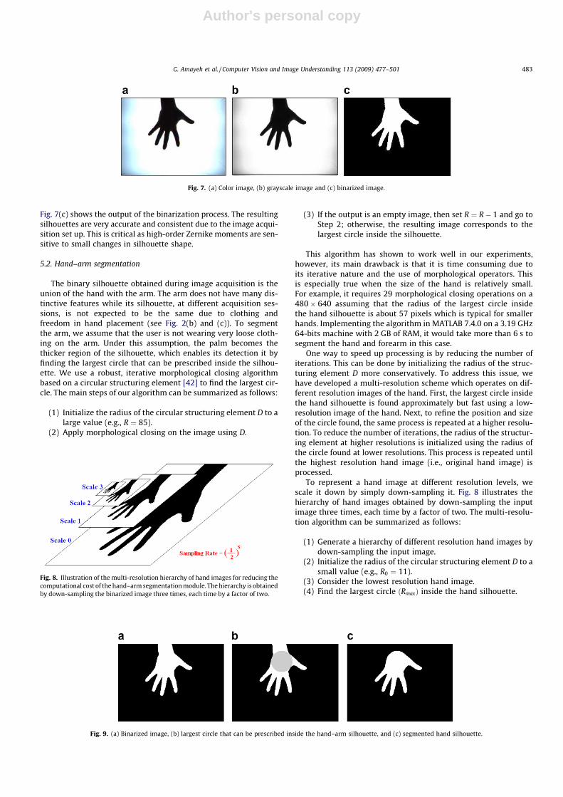
Fig. 7(c) shows the output of the binarization process. The resultingsilhouettes are very accurate and consistent due to the image acqui-sition set up. This is critical as high-order Zernike moments are sen-sitive to small changes in silhouette shape.
5.2. Hand–arm segmentation
The binary silhouette obtained during image acquisition is theunion of the hand with the arm. The arm does not have many dis-tinctive features while its silhouette, at different acquisition ses-sions, is not expected to be the same due to clothing andfreedom in hand placement (see Fig. 2(b) and (c)). To segmentthe arm, we assume that the user is not wearing very loose cloth-ing on the arm. Under this assumption, the palm becomes thethicker region of the silhouette, which enables its detection it byfinding the largest circle that can be prescribed inside the silhou-ette. We use a robust, iterative morphological closing algorithmbased on a circular structuring element [42] to find the largest cir-cle. The main steps of our algorithm can be summarized as follows:
(1) Initialize the radius of the circular structuring element D to alarge value (e.g., R ¼ 85).
(2) Apply morphological closing on the image using D.
(3) If the output is an empty image, then set R ¼ R� 1 and go toStep 2; otherwise, the resulting image corresponds to thelargest circle inside the silhouette.
This algorithm has shown to work well in our experiments,however, its main drawback is that it is time consuming due toits iterative nature and the use of morphological operators. Thisis especially true when the size of the hand is relatively small.For example, it requires 29 morphological closing operations on a480� 640 assuming that the radius of the largest circle insidethe hand silhouette is about 57 pixels which is typical for smallerhands. Implementing the algorithm in MATLAB 7.4.0 on a 3.19 GHz64-bits machine with 2 GB of RAM, it would take more than 6 s tosegment the hand and forearm in this case.
One way to speed up processing is by reducing the number ofiterations. This can be done by initializing the radius of the struc-turing element D more conservatively. To address this issue, wehave developed a multi-resolution scheme which operates on dif-ferent resolution images of the hand. First, the largest circle insidethe hand silhouette is found approximately but fast using a low-resolution image of the hand. Next, to refine the position and sizeof the circle found, the same process is repeated at a higher resolu-tion. To reduce the number of iterations, the radius of the structur-ing element at higher resolutions is initialized using the radius ofthe circle found at lower resolutions. This process is repeated untilthe highest resolution hand image (i.e., original hand image) isprocessed.
To represent a hand image at different resolution levels, wescale it down by simply down-sampling it. Fig. 8 illustrates thehierarchy of hand images obtained by down-sampling the inputimage three times, each time by a factor of two. The multi-resolu-tion algorithm can be summarized as follows:
(1) Generate a hierarchy of different resolution hand images bydown-sampling the input image.
(2) Initialize the radius of the circular structuring element D to asmall value (e.g., R0 ¼ 11).
(3) Consider the lowest resolution hand image.(4) Find the largest circle ðRmaxÞ inside the hand silhouette.
Fig. 7. (a) Color image, (b) grayscale image and (c) binarized image.
Fig. 8. Illustration of the multi-resolution hierarchy of hand images for reducing thecomputational cost of the hand–arm segmentation module. The hierarchy is obtainedby down-sampling the binarized image three times, each time by a factor of two.
Fig. 9. (a) Binarized image, (b) largest circle that can be prescribed inside the hand–arm silhouette, and (c) segmented hand silhouette.
G. Amayeh et al. / Computer Vision and Image Understanding 113 (2009) 477–501 483

Author's personal copy
(5) Set the radius of the circular structuring element D to2� Rmax þ 2.
(6) If a higher resolution image is available, go to Step 4; other-wise, stop.
In our experiments, the multi-resolution hierarchy containsfour levels, that is, we scale down the original image three times.The algorithm starts by processing the lowest resolution hand im-age which is eight times smaller than the original one. At this level,the largest circle prescribed inside the hand silhouette can befound very quickly (i.e., typically, within 4–5 iterations). Whenconsidering higher resolutions, the number of iterations stayslow by initializing the radius of the structuring element conserva-tively based on the size of the circle found at lower resolutions.Considering the small hand example mentioned earlier, it takesfive iterations at the lowest resolution image and only two itera-tions at the highest resolution (i.e., original) image. Overall, seg-menting the hand and forearm reduces processing time from 6 to0.69 s for this example. The average processing time on 250 sampleimages was 0.58 s.
Fig. 9(b) shows the output of the algorithm on the sample imageshown in Fig. 9(a). Once the largest circle has been found, the armcan be segmented by finding its intersection with the circle and theboundary of the hand–arm region. Fig. 9(c) shows the resultinghand silhouette after discarding the arm region.
5.3. Palm–finger segmentation
To simplify finger segmentation, subjects were instructed tostretch their hand during image acquisition in order to avoidtouching fingers; however, finger motion was unavoidable. Severalsample images collected from the same subject are shown in Fig. 2.As it can be observed, the relative position of the fingers varies sig-nificantly from sample to sample. The processing steps of the fin-
ger segmentation module are shown in Fig. 10. First, amorphological closing operator based on a circular disk is appliedon the hand image as shown in Fig. 10(a). The radius of the struc-turing element was experimentally set to 25 pixels, making itthicker than the widest finger in our database. The closing opera-tion filters out the fingers from the silhouette as shown inFig. 10(c). The remaining part of the silhouette corresponds tothe palm, which is subtracted from the hand image to obtain thefinger segments as shown in Fig. 10(d). It should be mentioned thatan alternative way to segment the fingers from palm is by detect-ing certain landmark points on the hand, such as fingertips and val-leys. This solution, however, would be more prone to errors due toinaccuracies in landmark detection.
To identify each of the fingers quickly, we assume that handrotations are less than 45�. In our prototype system, larger rota-tions would correspond to purposeful, unnatural hand placementby the users. In general, it would be possible to deal with largerrotations by using additional information for each finger such aslength, width, aspect ratio, and area. To extract each finger andthe back of the palm, we use connected component analysis [43].
5.4. Post-processing of finger regions
A closer examination of the results shown in Fig. 10(d) revealthat the segmented fingers have sharp tails at the locations wherethey meet the palm. The curvature of the hand contour at theselocations is smoother for the little, point, and thumb fingers asshown in Fig. 11(left). As a result, there might be significant differ-ences in the length of the tails corresponding to these fingers asshown in Fig. 11(a), where different samples from the same subjectare shown. In some cases, especially when the hand is small (i.e.,mostly for female hands), there are significant differences in thelength of the tails, which introduces significant errors in the com-putation of the Zernike moments. This can be illustrating by
Fig. 10. (a) Hand silhouette, (b) structuring element, (c) the result of morphological closing and (d) the result of subtracting the back of the palm from the hand silhouette.
Fig. 11. (Top) The junctions of finger with the palm in the hand counter where their curvature is too smoother than the others. (Right) Pairs of segmented little, point, andthumb fingers. Each pair corresponds to two different samples of the same subject. (a) Before applying the additional step, and (b) after applying the additional step.
484 G. Amayeh et al. / Computer Vision and Image Understanding 113 (2009) 477–501

Author's personal copy
observing the differences in the size of the circles enclosing the fin-gers in Fig. 11(a) versus those in Fig. 11(b) where the tails havebeen removed using post-processing.
To keep these errors as low as possible, we post-process eachfinger by applying an extra morphological closing step as shownin Fig. 11(b). The structuring element was chosen experimentallyto be a simple 4 by 4 square with values set to one. Table 5 illus-trates the effect of this step by showing the normalized distancesbetween the pairs of corresponding fingers shown in Fig. 11. Obvi-ously, this step improves matching scores considerably.
Tables 6 and 7, present statical results (i.e., mean and variance)to further support the benefits of this step in terms of matchingand non-matching distances. For each finger, we have computedall possible matching and non-matching distances in our database,before and after post-processing, using Zernike features up to order20 (121 features). Since our database contains 101 people with 10images per person, there were 4545 matching distances and1,010,000 non-matching distances for each finger. Our results indi-cate that finger post-processing reduces the overlap betweenmatching and non-matching distances significantly in the case ofthe little, point, and thumb fingers; however, it does not seem tohave an important effect in the case of the ring and middle fingers.This was an expected result since there are more segmentationproblems with these fingers due to their greater motion freedom.
6. Feature extraction
In this step, we represent the geometry of the back of the palmand the fingers implicitly using Zernike moments. A critical issue atthis stage is choosing the order of Zernike moments appropriatelyin order to capture sufficient shape information for verification andidentification purposes. Our experimental results indicate that
capturing important shape details for verification/identificationpurposes requires using high-order moments.
In general, using very high-order moments would preserve moreand more information. Fig. 12 demonstrates this idea using a300� 300 binary image, shown at the top left corner, which containsinformation at various levels of detail. The reconstructed imagesusing moments up to order 20 contain only a rough silhouette ofthe wolf. The reconstructions using moments up to order 50 showthe head of wolf clearly, however, the letters in the logo are stillblurred. Using orders up to 70 improves the reconstruction of the let-ters in the logo as well. Using very high-orders is not practical, how-ever, due to information redundancy and computational complexityissues. Moreover, Liao and Pawlak [44] have shown that there is aninherent limitation in the precision of arbitrary high-order Zernikemoments due to the circular geometry of the domain.
Here, we used the average reconstruction error (i.e., Eq. (8)) on alarge number of palm and finger images to decide the appropriateorder for our application. Our objective was to preserve importantdetails while keeping the orders as low as possible. Specifically, byanalyzing the reconstruction error, the maximum order chosen forthe fingers was 20 while the maximum order chosen for the backof the palm was 30. Fig. 13(a) shows several finger reconstructionsusing different orders. Fig. 13(b) shows the reconstruction errorusing different orders in this case. As it can be observed, the erroralmost saturates for orders higher than 40. This is also visually evi-dent from the finger reconstructions shown in Fig. 13(a). In gen-eral, using orders higher than 20 does not offer majorimprovements. Therefore, to keep computational cost low, thehighest order chosen in the case of fingers was 20. Similar experi-ments and analysis in the case of the back of the palm revealed thatthe highest order useful for verification/identification purposeswas 30. It should be mentioned that the reconstruction criterionused here to select the order of Zernike moments might not yieldthe most discriminant moments [45]. In the future, we plan toinvestigate feature selection schemes [46] to select a subset of dis-criminant Zernike moments for each part of the hand.
Using a similar analysis to represent the geometry of the wholehand, we found that orders as high as 70 were required. Fig. 14(a)shows a hand image while Fig. 14(b) shows several reconstructionsusing different orders. The reconstruction error is shown to theright of Fig. 14. Clearly, using a component-based representationof the hand offers major computational savings.
Table 5The effect of the extra morphological closing operator on the normalized distancesbetween the Zernike moments (up to order 20) of the segmented finger pairs before(Fig. 11(a)) and after (Fig. 11(b)) the extra step.
Pair of fingers dbefore dafter
Little 0.5904 0.0901Point 0.7881 0.1135Thumb 0.7424 0.1253
Table 6Mean and Variance of matching distances for each finger before and after post-processing.
Finger lbefore lafter rbefore rafter
Little 0.1724 0.0998 0.1039 0.0873Ring 0.1085 0.0817 0.1004 0.0952Middle 0.0823 0.0810 0.0983 0.0995Point 0.1928 0.0716 0.1287 0.0886Thumb 0.1843 0.1205 0.1262 0.0843
Table 7Mean and Variance of non-matching distances of each finger before and after post-processing.
Finger lbefore lafter rbefore rafter
Little 0.3564 0.2869 0.1162 0.0341Ring 0.3072 0.2861 0.0531 0.0289Middle 0.2859 0.2870 0.0290 0.0268Point 0.3672 0.2715 0.1454 0.0248Thumb 0.4136 0.3120 0.1216 0.0616
Fig. 12. Original and reconstructed images using different orders of Zernikemoments.
G. Amayeh et al. / Computer Vision and Image Understanding 113 (2009) 477–501 485

Author's personal copy
Computing very high-order Zernike moments is quite computa-tionally expensive, especially when precision is a requirement. Thealgorithm proposed in Section 4.2 was initially implemented inC++ using arbitrary precision arithmetic (i.e., 200 digits) on a2.66 GHz pentium IV with 256 MB memory. In this case, it takesabout 6 min to compute Zernike moments up to order 70, whileit only takes 35 s to compute Zernike moments up to order 30.We have verified experimentally that moments up to order 30can be computed quite accurately without resorting to arbitraryprecision arithmetic. In our application, using double precision in-stead of arbitrary precision to compute moments up to order 36yields an error less than 0:5%. Using double precision in C++ ona 3.19 GHz 64-bits machine with 2 GB of RAM, it takes less than0.01 s on the average to compute moments up to order 30. Thetime savings using double precision are significant and can be fur-ther improved by computing the Zernike moments of differentparts of the hand in parallel. In practice, a hybrid implementationcan be employed where the use of arbitrary precision arithmetic isrestricted only to orders higher than 36, therefore, reducing com-putational complexity. It should be mentioned that using featureselection [46] to choose a subset of discriminant Zernike moments,as mentioned earlier, will further decrease time requirements.
Hardware implementations could also be considered for real timeapplications [47,48].
7. Fusion
At this step, we fuse information from different parts of thehand to improve verification/identification accuracy and robust-ness. In general, fusion can be implemented at different levels. Inthis paper, we have experimented with three different fusion strat-egies: feature-level, score-level, and decision-level fusion.
In feature-level fusion, the features extracted from the fingersand the back of the palm can be fused to create a more compactand powerful feature set. Commonly, feature-level fusion is per-formed using dimensionality reduction or feature selection [45].In score-level fusion, the matching scores of the fingers and thepalm can be fused to obtain an overall score. The sum rule or theweighted-sum rule are common score-level fusion techniques[49]. In decision-level fusion, verification/identification resultsbased on different parts of the hand can be fused to obtain an over-all authentication decision. Majority voting, and AND/OR rules arewidely used decision-level fusion techniques [49]. We providemore details in the following subsections.
Fig. 13. (a) Original image (top left) and reconstructed images (left to right, top to bottom) up to order 2, 5, 10, 20, 30, 40, 50, 60, and 70, (b) reconstruction error.
Fig. 14. (a) Original and (b) reconstructed images (left to right, top to bottom) up to order 10, 20, 30, 40, 50, 60, 70, 80, and 90, (right) reconstruction error.
486 G. Amayeh et al. / Computer Vision and Image Understanding 113 (2009) 477–501
Author's personal copy
7.1. Feature-level fusion using Principal Component Analysis
Using Principal Components Analysis (PCA) [45] for feature-le-vel fusion is a very common approach. According to this ap-proach, the feature vectors of the back of the palm and thefingers are combined into a single feature vector. Then, PCA is ap-plied to map them into a lower dimensional space. The resultingPCA features are linear combinations of the original finger andpalm features.
7.2. Score-level fusion using weighted sum
The weighted-sum rule has been extensively investigated in theliterature and it is probably the most straightforward fusion strat-egy at the score-level. First, we compute matching scores betweencorresponding parts of the hand (i.e., back of the palm and fingers)in the query and the template. Then, the matching scores are com-bined into a single score using a weighted-sum rule as shownbelow:
SðQ ; TÞ ¼X6
i¼1
aiSðQi; TiÞ ð11Þ
where S is the similarity measure (e.g., Euclidean distance) betweenthe query Q and the template T. Qi and Ti represent the ith part ofthe hand, i ¼ 1;2; . . . ;6. In our system, the first five parts correspondto the little, ring, middle, point and thumb fingers while the sixthpart corresponds to the back of the palm. The parameters ai arethe weights associated with the ith part of the hand; they need tosatisfy the following constraint:
X6
i¼1
ai ¼ 1 ð12Þ
The key issue with this method is determining a set of appropri-ate weight values.
7.3. Score-level fusion using Support Vector Machines
A Support Vector Machine (SVM) is a binary classifier that mapsinput patterns X to output labels y 2 �1;1 [45]. In general, an SVMhas the following form:
f ðXÞ ¼Xi2X
aiyiKðX;XiÞ þ b ð13Þ
where ai are the Lagrange multipliers, X corresponds to the indicesof the support vectors for which ai–0, b is a bias term, X is an inputvector, and KðX;XiÞ is a kernel function. Classification decisions arebased on whether the value f ðXÞ is above or below a threshold. Wehave employed SVM to implement an alternative score-level fusionstrategy. Given a pair of hands to be verified, the input vector X iscomposed of the matching scores between corresponding parts ofthe hand. Assigning the input vector to the class ‘‘1” implies thatboth hands come from the same subject while assigning it to theclass ‘‘�1” implies that they come from different subjects.
7.4. Decision-level fusion using majority voting
Majority voting is among the most straightforward decision-le-vel fusion strategies. In this case, the final decision is based on theoutput results of several matchers. In the context of our applica-tion, first we verify/identify each subject using different parts ofthe hand (i.e., fingers and palm). Then, if three or more parts ofthe hand yield a positive verification/identification, then verifica-tion/identification is considered successful; otherwise, the subjectis rejected.
8. Experimental results and comparisons
In order to evaluate the proposed system, we have collectedhand images from 101 people of different age, sex and ethnicity.For each subject, we collected 10 images of their right hand duringthe same session. To test the performance of our system on timepassage, additional hand images were collected in a separate ses-sion from 20 of these subjects 9 months later. During each session,subjects were asked to stretch their hand and place it inside asquare area drawn on the surface of the lighting table; no otherrestrictions were imposed on the subjects. To capture differentsamples within each session, subjects were asked to remove theirhand from the lighting table, relax it for a few seconds, and thenplace it back again. We report results both on hand-based verifica-tion and recognition.
8.1. Hand-based verification results
For person verification, one must differentiate a genuine handfrom imposter hands as the user provides his/her hand image insupport of his/her claimed identity. For this purpose, we calculatethe Euclidean distance between the hand of the applicant and eachof his/her templates in the database and take the minimum dis-tance D:
D ¼ minifjjQ � Tijjg; i ¼ 1; . . . ; k ð14Þ
where Q corresponds to the query hand, Ti corresponds to the ithtemplate of a given subject in the database, and k corresponds tothe number of templates of that subject. If D is below a threshold,verification is successful; otherwise, the subject is rejected.
In the following subsections, we present the results of severaldifferent experiments. First, we investigate the performance of abaseline system which uses the whole hand for verification. Then,we investigate the verification power of different parts of the handby implementing several systems that perform verification usingeach part of the hand separately. Finally, we evaluate the proposedsystem which fuses information from different parts of the handfor verification.
8.1.1. Verification using whole handTo provide a baseline for comparisons, first we experimented
with a simpler system that uses the whole hand for verification.In this case, a global representation of the hand is used for verifica-tion. Preliminary results based on this approach have been re-ported in an earlier work [20], however, this section presentsresults based on more comprehensive experiments and a largerdatabase.
The first step in this baseline system is to separate the arm fromthe hand using the methodology presented in Section 5. Then, thegeometry of the silhouette of the whole hand is represented usingZernike moments. As mentioned in Section 6, capturing the shapedetails of the whole hand requires computing Zernike moments upto order 70; this yields feature vectors containing 1296components.
To test the approach, we used different number of samples(i.e., 3, 4, and 5) for each subject as enrollment templates. To ac-count for regularities in the choice of the templates, we repeatedthe experiments 30 times, each time choosing the enrollmenttemplates randomly. The remaining samples were used to con-struct matching and non-matching sets and estimate the FalseAcceptance Rate (FAR) and False Reject Rate (FRR) of the system.Fig. 15(a) shows the average ROC curves obtained using this pro-cedure. As it can be observed, using more templates improvesverification accuracy, however, it this would also increase verifi-cation time.
G. Amayeh et al. / Computer Vision and Image Understanding 113 (2009) 477–501 487

Author's personal copy
Since the size of the feature vectors was very high, we have alsoexperimented with PCA to reduce their dimensionality. Using asimilar procedure, we repeated the experiments 30 times, choosing3, 4, and 5 templates randomly each time. In each experiment, theeigenvectors were computed from the covariance matrix of the en-rolled templates by preserving 99:9% of the information. Fig. 15(b)shows the average ROC curves obtained using PCA features. Table 8provides comparative results in terms of the Equal Error Rate (EER),as well as the mean, and standard deviation of the True AcceptanceRate (TAR) when FAR ¼ 0:1%. As it can be observed, PCA improvesverification results by increasing TAR while at the same timereducing its standard deviation. Overall, the best verification per-formance using the whole hand was obtained with PCA featuresand five enrollment templates per subject.
8.1.2. Verification using different parts of the handTo investigate the verification power of different parts of the
hand, we experimented with several systems, each performing ver-ification using a different part of the hand. In this case, local repre-sentations of the hand were used for verification. Each system wastested using five enrollment templates (i.e., using less templatesresults in lower accuracy) and repeating the experiments 30 timesas before by choosing the enrollment templates randomly eachtime. For each system, we report the average ROC curves obtained.To ensure that the comparison was fair, we used the same trainingand test data as in the case of the whole hand. To calculate the dis-
tance between corresponding parts of the hand (i.e., fingers or backof the palm) in the query and the template hands, we used Eq. (14)as before.
Fig. 16 (blue solid line) shows the average ROC curves obtainedfor each part of the hand. In addition, we performed experimentsusing PCA to reduce the dimensionality of the feature vectors. Ineach case, we preserved 99.9% of the information. Fig. 16 (reddashed line) shows the results obtained in this case. Also, Table 9shows specific details for each case using raw and PCA featureswhen FAR ¼ 0:1%. As it can be observed, PCA features improveaccuracy slightly only in the case of the back of the palm.
To illustrate performance differences between various parts ofthe hand more clearly, we have plotted all six ROC curves, corre-sponding to raw features, on the same graph shown in Fig. 17. Asit can be observed, the best performance was obtained using theindex, middle, and ring fingers. Among them, the index yieldedthe best results. On the other hand, the thumb yielded the lowestperformance among all parts. This can be explained by the fact thatthe thumb has higher degree of freedom than any other part, mak-ing it difficult to fix its position.
8.1.3. Verification by fusing information from different parts of thehand
In this subsection, we report results by fusing information fromdifferent parts of the hand for verification. To ensure that our re-sults are comparable to the previous experiments, we used thesame evaluation methodology as well as the same training and testsets. Using feature-level fusion, we combined the feature vectors ofeach part of the hand into a single feature vector yielding 861 fea-tures. Using PCA and keeping 99.9% of the information, yields be-tween 72 and 81 features. In the case of score-level fusion usingthe weighted-sum rule, we experimented with different sets ofweight values, using the results from the previous section as aguide. The best results, reported below, were obtained using thefollowing values: w1 = 0.5/12 (little finger), w2 = 2.5/12 (ring fin-ger), w3 = 3.0/12 (middle finger), w4 = 4.5/12 (index finger),w5 = 0.5/12 (thumb), and w6 = 1.0/12 (back of the palm). The
Fig. 15. Average ROC curves using whole hand for verification: (a) raw features, (b) PCA features. Each experiment was repeated 30 times, using 3, 4, and 5 enrollmenttemplates per subject.
Table 8Verification using whole hand: comparison using raw and PCA features.
Enrollment size 3 4 5
Features Raw PCA Raw PCA Raw PC
Number of features 1296 182–203 1296 221–242 1296 252–274EER ð%Þ 3.55 2.69 2.95 2.38 2.78 2.21TAR ð%Þ (FAR = 1%) 94.22 95.84 95.62 96.66 96.26 97.06rTAR ð%Þ (FAR = 1%) 1.62 1.60 1.61 1.26 1.27 1.16
Table 9Comparison using different parts of the hand for verification: raw versus PCA features.
Finger Little Ring Middle Index Thumb Palm
Feature Raw PCA Raw PCA Raw PCA Raw PCA Raw PCA Raw PCA
Number of features 121 23–24 121 18 121 16 121 16 121 43–45 256 87–96EER ð%Þ 1.77 1.78 1.62 1.66 1.28 1.44 0.93 0.98 3.62 3.53 2.05 1.90TAR ð%Þ (FAR = 1%) 96.9 96.6 97.3 97.1 98.3 97.8 99.2 99.1 92.2 92.0 96.9 97.5rTAR ð%Þ (FAR = 1%) 1.3 1.41 0.79 0.8 0.54 0.72 0.34 0.42 1.7 1.76 1.23 1.16
488 G. Amayeh et al. / Computer Vision and Image Understanding 113 (2009) 477–501

Author's personal copy
weights were fixed in all experiments. In the case of score-level fu-sion using SVMs, we experimented using different parameter val-ues. The best results (i.e., on the average) were obtained usingthe Gaussian kernel with r ¼ 0:01 and C ¼ 1 (i.e., cost term). Theseparameter values were kept fixed in all of our experiments.
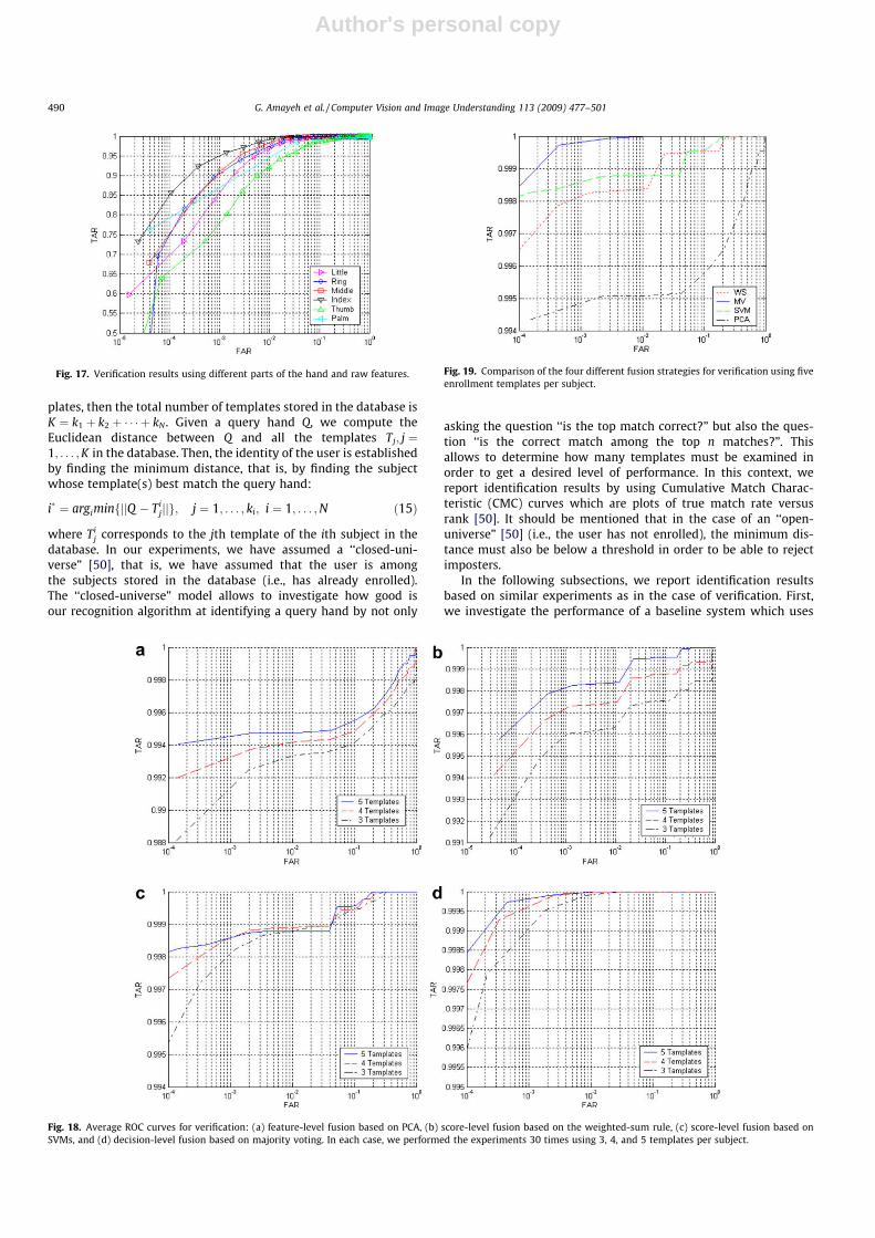
Fig. 18 shows the average ROC curves obtained for each fusionstrategy using 3, 4, and 5 templates per subject. In general, usingmore enrollment templates per subject improves verification per-formance although it would also increase verification time. Amongthe four fusion strategies considered, decision-based fusion per-forms best. Between the two different decision-based fusionschemes considered, majority voting performs best. Feature levelfusion based on PCA had the lowest performance, however, itshould be mentioned that PCA reduces the size of templates morethan 10 times.
Fig. 19 compares all fusion strategies on the same graph assum-ing five enrollment templates. Additional details are shown in Ta-ble 10 which compares the fusion strategies, using five enrollmenttemplates, in terms of EER and the mean and the standard devia-tion of TAR when FAR ¼ 0:1%. As it can be observed, all fusion haveimproved verification performance, for example, TAR is more than99.4% when FAR is more than 0.1%. Table 11 shows specific detailsin the case of majority voting.
8.2. Hand-based identification results
For person identification, the user does not provide any identityclaim, but the system must find out the user’s identity by compar-ing him/her to a database of enrolled users. Assuming that thereare N subjects in the database and that each subject i has ki tem-
Fig. 16. Average CMC curves using different parts of the hand for identification: (a) little, (b) ring, (c) middle, (d) index, (e) thumb, and (f) back of the palm. Each experimentwas performed 30 times using five samples for each subject as enrollment templates.
G. Amayeh et al. / Computer Vision and Image Understanding 113 (2009) 477–501 489
Author's personal copy
plates, then the total number of templates stored in the database isK ¼ k1 þ k2 þ � � � þ kN . Given a query hand Q, we compute theEuclidean distance between Q and all the templates Tj; j ¼1; . . . ;K in the database. Then, the identity of the user is establishedby finding the minimum distance, that is, by finding the subjectwhose template(s) best match the query hand:
i� ¼ argiminfjjQ � Tijjjg; j ¼ 1; . . . ; ki; i ¼ 1; . . . ;N ð15Þ
where Tij corresponds to the jth template of the ith subject in the
database. In our experiments, we have assumed a ‘‘closed-uni-verse” [50], that is, we have assumed that the user is amongthe subjects stored in the database (i.e., has already enrolled).The ‘‘closed-universe” model allows to investigate how good isour recognition algorithm at identifying a query hand by not only
asking the question ‘‘is the top match correct?” but also the ques-tion ‘‘is the correct match among the top n matches?”. Thisallows to determine how many templates must be examined inorder to get a desired level of performance. In this context, wereport identification results by using Cumulative Match Charac-teristic (CMC) curves which are plots of true match rate versusrank [50]. It should be mentioned that in the case of an ‘‘open-universe” [50] (i.e., the user has not enrolled), the minimum dis-tance must also be below a threshold in order to be able to rejectimposters.
In the following subsections, we report identification resultsbased on similar experiments as in the case of verification. First,we investigate the performance of a baseline system which uses
Fig. 18. Average ROC curves for verification: (a) feature-level fusion based on PCA, (b) score-level fusion based on the weighted-sum rule, (c) score-level fusion based onSVMs, and (d) decision-level fusion based on majority voting. In each case, we performed the experiments 30 times using 3, 4, and 5 templates per subject.
Fig. 19. Comparison of the four different fusion strategies for verification using fiveenrollment templates per subject.
Fig. 17. Verification results using different parts of the hand and raw features.
490 G. Amayeh et al. / Computer Vision and Image Understanding 113 (2009) 477–501

Author's personal copy
the whole hand for identification purposes. Then, we investigatethe recognition power of different parts of the hand by implement-ing several systems that perform identification using each part ofthe hand separately. Finally, we evaluate the proposed systemwhich fuses information from different parts of the hand foridentification.
8.2.1. Identification using whole handTo provide a baseline for comparisons, first we experimented
with a simpler system that uses the whole hand for identification.In this case, a global representation of the hand was used for identi-fication. Fig. 20(a) shows the average CMC curves obtained using thisprocedure while Fig. 20(c) shows the corresponding standard devia-tions. As it can be observed, using more templates improves recogni-tion accuracy, however, it also increases recognition time. Since the
size of the feature vectors was very high, we have also experimentedwith PCA to reduce their dimensionality. Using a similar procedurelike in the case of verification (i.e., see Table 8), we obtained the aver-age CMC curves shown in Fig. 20(b). The corresponding standarddeviations are shown in Fig. 20(d). As it can be observed, PCA has al-most identical performance to the approach using raw features.
8.2.2. Identification using different parts of the handTo investigate the identification power of different parts of the
hand, we experimented with several systems, each performing rec-ognition using a different part of the hand. Each system was testedusing five enrollment templates and repeating the experiments 30times as before by choosing the enrollment templates randomlyeach time. For each system, we report the average CMC curve ob-tained. To ensure that the comparison was fair, we used the sametraining and test data as in the case of the whole hand. To calculatethe distance between corresponding parts of the hand (i.e., fingersor back of the palm) in the query and the template hands, we usedEq. (15) as before. Fig. 16 (blue solid line) shows the average CMCcurves obtained for each part of the hand. In addition, we per-formed experiments using PCA to reduce the dimensionality ofthe feature vectors. In each case, we preserved 99.9% of the infor-mation (i.e., see Table 9, for details). Fig. 16 (red dashed line) showsthe results obtained in this case. As it can be observed, PCA hasslightly worse recognition accuracy to the approach using raw fea-tures, especially for low ranks.
To illustrate performance differences between various parts ofthe hand more clearly, we have plotted all six CMC curves, cor-responding to raw features, on the same graph shown inFig. 22(a). The corresponding standard deviations are shown inFigs. 20(b) and 22(b). As it can be observed, the best perfor-mance was obtained using the index, middle, and ring fingers.
Fig. 20. Average CMC curves using whole hand for identification: (a) raw features, (b) PCA features, (c) standard deviation of raw features, and (d) standard deviation of PCAfeatures. Each experiment was repeated 30 times, using 3, 4, and 5 enrollment templates per subject.
Table 10Detailed comparison of different fusion strategies for verification using five enroll-ment templates per subject.
Method PCA Weighted sum Majority voting SVM
EER ð%Þ 0.523 0.052 0.044 0.136TAR ð%Þ (FAR = 0.1%) 99.47 99.98 99.98 99.86rTAR ð%Þ (FAR = 0.1%) 0.231 0.052 0.059 0.12
Table 11Fusion using majority voting for verification: mean and standard deviation of TARwhen FAR ¼ 0:1%.
No. of training vectors 3 4 5
TAR (%) 99.92 99.96 99.98rTAR (%) 0.1115 0.0697 0.0594
G. Amayeh et al. / Computer Vision and Image Understanding 113 (2009) 477–501 491

Author's personal copy
Among them, the index yielded the best recognition results (i.e.,both higher accuracy and lower standard deviation). On theother hand, the thumb yielded the lowest recognition perfor-mance among all parts (i.e., both worst accuracy and higherstandard deviation). These results are consistent with those ob-tained for verification.
8.2.3. Identification by fusing information from different parts of thehand
In this subsection, we report results by fusing information fromdifferent parts of the hand for identification. In particular, wetested the same fusion strategies except score-level fusion usingSVMs since the use of SVMs for identification would requireextending SVMs to multiple-class classification. Such an extensionwould require a large number of training samples (i.e., enrollmenttemplates) per subject to guarantee good performance. As previ-ously, we used the same evaluation methodology as well as the
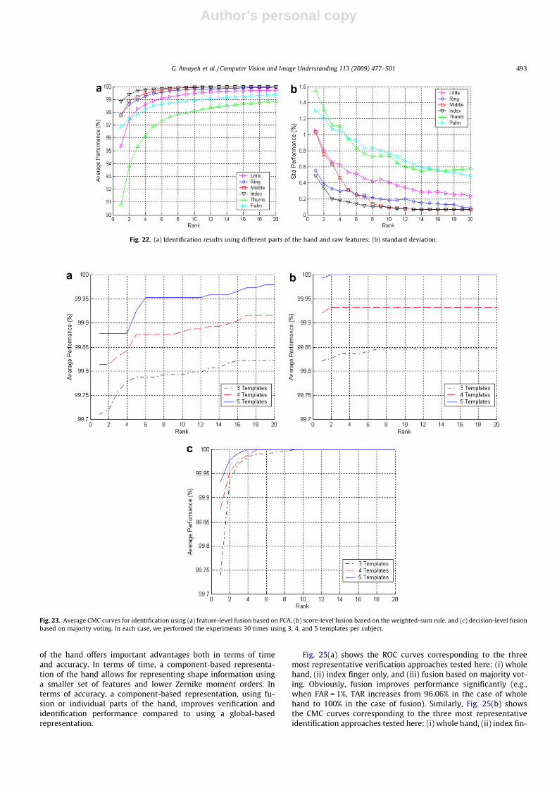
same training and test sets for consistency. Fig. 23 shows the aver-age CMC curves obtained for each fusion strategy using 3, 4, and 5templates per subject. In general, using more enrollment templatesper subject improves identification performance although it wouldalso increase identification time. Among the three fusion strategiesconsidered, score-level fusion had slightly better performance (i.e.,higher accuracy and lower standard deviation) for low ranks.Fig. 24(a) compares all three fusion strategies on the same graphassuming five enrollment templates. Fig. 24(b) shows the corre-sponding standard deviations.
8.3. Comparison between global-based and component-based handrepresentations
Representing the hand it terms of its components and per-forming verification or identification using different parts ofthe hand separately or fusing information from different parts
Fig. 21. Average ROC curves using different parts of the hand for verification: (a) little, (b) ring, (c) middle, (d) index, (e) thumb, and (f) back of the palm. Each experiment wasperformed 30 times using five samples for each subject as enrollment templates.
492 G. Amayeh et al. / Computer Vision and Image Understanding 113 (2009) 477–501
Author's personal copy
of the hand offers important advantages both in terms of timeand accuracy. In terms of time, a component-based representa-tion of the hand allows for representing shape information usinga smaller set of features and lower Zernike moment orders. Interms of accuracy, a component-based representation, using fu-sion or individual parts of the hand, improves verification andidentification performance compared to using a global-basedrepresentation.
Fig. 25(a) shows the ROC curves corresponding to the threemost representative verification approaches tested here: (i) wholehand, (ii) index finger only, and (iii) fusion based on majority vot-ing. Obviously, fusion improves performance significantly (e.g.,when FAR = 1%, TAR increases from 96.06% in the case of wholehand to 100% in the case of fusion). Similarly, Fig. 25(b) showsthe CMC curves corresponding to the three most representativeidentification approaches tested here: (i) whole hand, (ii) index fin-
Fig. 23. Average CMC curves for identification using (a) feature-level fusion based on PCA, (b) score-level fusion based on the weighted-sum rule, and (c) decision-level fusionbased on majority voting. In each case, we performed the experiments 30 times using 3, 4, and 5 templates per subject.
Fig. 22. (a) Identification results using different parts of the hand and raw features; (b) standard deviation.
G. Amayeh et al. / Computer Vision and Image Understanding 113 (2009) 477–501 493

Author's personal copy
ger only, and (iii) fusion based on weighted sum. Obviously, fusionimproves identification performance significantly (e.g., whenrank = 1, recognition accuracy increases from 96.75% in the caseof whole hand to almost 100% in the case of fusion).
It should be mentioned that the main reason that the baselineapproach (i.e., whole hand) did not perform very well is becauseit cannot tolerate well finger motion. As shown in Fig. 2(b) and(c), finger motion is unavoidable in different sample images ofthe same subject. Although Zernike moments can tolerate somedegree of finger motion(e.g., 6� rotation about the axis being per-pendicular to the joint of the finger with the palm), they are sensi-
tive to larger finger motions. Moreover, they cannot tolerate wellsituations where the hand is bent at the wrist. Fig. 26, illustratesthat finger motion affects the Zernike moments of all orders. Seg-menting the hand in different parts alleviates these problems.
8.4. Comparisons with other approaches
In this section, we report both qualitative and quantitative re-sults between our method and methods reported in the literature.Table 12 shows a qualitative comparison of the performance of oursystem and methods reported in the literature. Since there is no
Fig. 24. (a) Comparison of different fusion strategies for identification using five enrollment templates per subject; (b) Standard deviation.
Fig. 25. Comparison of the three most representative approaches for (a) verification and (b) identification, using five enrollment templates per subject: (i) whole hand, (ii)index finger, and (iii) majority voting (for verification) and weighted sum (for identification).
Fig. 26. (a and b) Images of the same hand containing finger motion, (c) normalized Zernike moment differences.
494 G. Amayeh et al. / Computer Vision and Image Understanding 113 (2009) 477–501

Author's personal copy
standard acquisition method and no benchmark databases, quanti-tative comparisons of different systems should be considered onlyindicative and not conclusive. To make the comparison more fair,for each study considered, we report several other factors includingthe number of subjects, the number of images per person, thenumber of enrollment templates, the use/no-use of pegs, the typeof features, and the distance measure. The results reported for oursystem in Table 12 correspond to using five enrollment templates.Our database size is comparable to most of the systems reported inthe table while our error rates are better than or equal even to theones reported on much smaller databases.
As it can be observed from Table 12, the majority of existingsystems employ hand geometric features for verification or identi-fication. It has been illustrated in the literature that these features
work well and can be computed efficiency. To better assess theperformance of our method, we have performed quantitative com-parisons, using the same database, to investigate whether Zernikedescriptors offer any potential advantages over geometric featuresin terms of robustness and accuracy. The geometric features usedin our experiments is a subset of the features introduced by San-chez-Reillo et al. [36,37]. Fig. 27(a) shows a sample image takenby their image acquisition system. They used 31 features (seeFig. 27(b)): width of four fingers and palm in different locations(18 features), height of middle and little fingers and palm (3 fea-tures), distances between the three inter-finger points (3 features)and angles between the inter-finger points and horizontal line (3features), distances between a middle point of the finger and themiddle point of the straight line between the inter-finger point
Table 12Qualitative comparison with existing methods.
System(s) # ofpeople
# of sampleper person
Pegs # oftemplate(s)
Feature(s) Similarity Verificationperformance
Identificationperformance
Jain [2] 50a 10 Yes 2 Geometric featuresk (16 features) Mahalanobis FAR = 0.01 —FRRb � 0.17
Wong [27] 22c 12–15 No 9 Thirteen geometric features andthree fingertip regionsk
GMM FAR = 0.022 —
FRR = 0.1111
Jain [30] 53d 2–15 Yes 1e Contour of five fingers Shape Distance FAR = 0.01 —FRRb � 0.06
Reillo [36,37] 20 10 Yes 5 Geometric featuresk deviation andangles between the inter-finger points(25 features)
Euclidean EERh = 0.049 97.0 � 10�2
Hamming Error ratef6 0.1
GMM
Ma [31] 20 6 No 1 4 B-Spline curves, length of thumband width of palm
Shape distance Error rate = 0.05 —
Kumar [4] 100 10 No 5 Geometric featuresk hand area(16 features) and
Correlation coefficient FAR = 0.01 —
FRRi � 0.32
Bulatov [29] 70g 10 No 5 Thirty geometric featuresk Nearest box FAR = 0.01 96.5 � 10�2
FRR = 0.03
Ribaric [28] 130 5 No 1 Twenty geometric featuresk Euclidean FAR = 0.153 —FRRj = 0.13
Xiong [26] 108 5 No 1 Width of four fingers at 45 differentlocation for each figure
Shape distance EER = 2.41 � 10�2 —
Yoruk [51] 100l 3 No 2 Independent Component Analysis(ICA) (200 features)
Cosine of the anglebetween vectors
EER = 1.15 � 10�2 98.81 � 10�2
Oden [55] 35 Not clear No Total 20 Combination of implicit polynomials andgeometric features (total 16 features)
Mahalanobis FAR = 0.01 95.0�10�2
FRR = 0.01
Our method 100 10 No 5 Zernike moments (861 features forfingersand palm)
Euclidean FAR = 0.01 99.98 � 10�2
FRR ¼ 0:0EER ¼ 4:38� 10�4
Error ratef = 7.42�10�4
a Out of 500 images, only 360 images were used and 140 images were discarded.b Estimated from ROC curve in [2].c A total of 288 images were used.d A total of 353 images were used.e Not all possible non-matching pairs were used.f The minimum error rate, which is the sum of FAR and FRR.g A total of 714 images were used.h This is the best EER using five training vectors and GMM for verification [37].i Hand geometry was used to improve the performance of palmprint-based verification. We have estimated FRR using only hand geometry information from the ROC curve
in [4] when FAR = 0.01.j A multi-modal biometric system was designed in [28] using fingerprint, palmprint, and hand geometry. The FAR and FRR reported here relates to hand geometry only, see
[28].k Geometric features such as length and width of the fingers, width of palm, thickness of hand and middle finger, etc.l The database includes 458 people with three samples per person. EER has been reported for different populations (i.e., 20,35,50,100, and 458).
G. Amayeh et al. / Computer Vision and Image Understanding 113 (2009) 477–501 495

Author's personal copy
and the last height where the finger width is measured (4 features).However, their image acquisition system uses a mirror to capture aside view of the hand in addition to a top view of the hand asshown in Fig. 27(a). Since our system captures a top view of thehand only, we cannot extract the height of the little and middle fin-gers as well as the palm (3 features). Therefore, we have used only28 features in our experimental comparisons. Fig. 27(c) shows themain distances measured on the binarized hand images from ourdatabase.
Systems employing pegs to fix the position of the hand, such as[36,37], use predestined axes to facilitate feature extraction. In thecase of peg-free systems, several landmarks on the hand, such asfingertips and valleys, must be extracted in order to define thesame or similar axes [26,31,27,51]. Here, we compute the curva-ture of the hand boundary to extract the fingertip and valley loca-tions by detecting curvature minima and maxima. The samemethodology has been employed in several other peg-free systemsincluding [31,26,27]. We provide more details about the landmarksextraction algorithm in the next section.
Fig. 28(a) and (b) shows the performance of hand-basedauthentication (i.e., using majority voting) and identification (i.e.,using weighted sum) between our method based on Zernikedescriptors and the method of [36,37] based on geometric features.In these experiments, five templates per person were employed forenrollment while the rest of them were used for testing. We reportthe average performance as before by repeating each experiment30 times. As it can be observed, system performance using Zernikedescriptors is superior to using geometric features both in the caseof verification and identification. Therefore, Zernike descriptorsseem to be more powerful compared to geometric features. Interms of time, as we discussed in Section 6, it takes less than0.01 s on the average to compute moments up to order 30 on a3.19 GHz 64-bits machine with 2GB of RAM, assuming double pre-cision. Table 13 compares the time requirements of the proposed
method and the method based on geometric features. Althoughthe preprocessing step of the proposed method is more time con-suming, it is most robust than detecting landmark points on thehand as illustrated in the next section.
8.5. Comparison between morphological-based finger segmentationversus landmarks-based finger segmentation
It could be claimed that segmenting the fingers and the palmcould be accomplished more efficiently using landmark points onthe hand than the algorithm described in Section 5 based on mor-phological operators. The purpose of the experiment reported inthis section is to investigate this claim by comparing finger seg-mentation using morphological operators, i.e., versus landmarkpoints. There are two main objectives behind our comparisons:(i) to investigate the computational efficiency of each methodand (ii) to investigate the effect of segmentation errors on verifica-tion and identification performance.
Fig. 29 illustrates how landmark points on the hand could beused for finger segmentation. In particular, Fig. 29(a) shows thelocation of the fingertips (blue dots)1 and valleys (red dots) while
Fig. 27. (a) A sample hand image taken using the image acquisition system in [36,37], (b) location of landmarks and features measured using the approach of [36,37], (c) themain features measured based the on approach of [36,37] on a sample hand image from our database.
Fig. 28. Comparison between geometric features and Zernike descriptors: (a) authentication results, (b) identification results.
Table 13Processing time for traditional and proposed methods. All numbers are in milli-seconds.
Method Preprocessing Feature extraction
Traditional Constructing axes/30a Geometric/20a
Proposed Hand–armsegmentation/580a
Palm–fingersegmentation/140a
Zernike/10b
a ms in MATLAB 7.4 on a 3.19 GHz, 64-bit machine with 2 GB RAM.b ms in Visual Studio 2005 on a 3.19 GHz, 64-bit machine with 2 GB RAM.
1 For interpretation of the references to color in the text, the reader is referred tothe web version of this paper.
496 G. Amayeh et al. / Computer Vision and Image Understanding 113 (2009) 477–501

Author's personal copy
Fig. 29(b) illustrates how to segment the fingers from the handusing these landmarks. It should be noted that, to segment thethumb, little finger, and index finger, some auxiliary points,namely A0, C0, and D0, need to be considered where ID0 is equal toID, HC0 is equal to HC, and EA0 is equal to EA [26,31,27,51].
Accurate extraction of landmark points on the hand is a crucialstep for peg-free systems [26,31,27,51]. A common approach to de-tect and extract the fingertips and valleys involves using curvatureinformation on the boundary of the hand [31,26,27]. The main ideais detecting curvature minima (i.e., fingertips) and maxima (i.e.,valleys); we have adopted this methodology here. The curvaturek of a planar curve, at a point on the curve, is defined as the instan-taneous rate of change of the slope of the tangent at that point withrespect to arc length, and it can be expressed as follows:
kðtÞ ¼ ð_xðtÞ€yðtÞ � _yðtÞ€xðtÞÞ2
ð _xðtÞ2 þ _yðtÞ2Þ32
ð16Þ
where _xðtÞ, €xðtÞ, _yðtÞ, and €yðtÞ are the first and second derivatives ofxðtÞ and yðtÞ, respectively, and ðxðtÞ; yðtÞÞ is the parametric represen-tation of the curve. To account for noise, xðtÞ and yðtÞ are typicallysmoothed using a Gaussian function gðt;rÞ [52,53]. The smoothedcurve curvature kðt;rÞ can be expressed as follows:
kðt;rÞ ¼ ð_Xðt;rÞ€Yðt;rÞ � _Yðt;rÞ€Xðt;rÞÞ2
ð _Xðt;rÞ2 þ _Yðt;rÞ2Þ32
ð17Þ
where _Xðt;rÞ and €Xðt;rÞ are defined at the convolution of xðtÞwithethe first and second derivatives of gðt;rÞ correspondingly. _Yðt;rÞ
and €Yðt;rÞ can be defined similarly. Before computing the curva-ture, the hand boundary is re-sampled at 1024, equal-distant,points [52,53]. Fig. 30(b) shows the curvature of the hand contourshown in Fig. 30(a). Choosing the value of r is critical to ensure bothgood detection and localization. In general, smaller r values lead tobetter localization, however, noise could give rise to false positives.On the other hand, larger r values reduce false positives but goodlocalization is difficult. To address this issue, multi-resolutionschemes have been proposed (i.e., curvature scale-space [52]), how-ever, time requirements are higher. Since our system producesimages of high quality, we have found that a r value equal to 20yields good detection and localization results.
It can be noted by observing Fig. 30(b) that the curvature of thefinger valley between the index finger and the thumb is muchsmaller compared to the other valleys. As a result, detecting andlocalizing point D is more difficult than the other three valleys.Moreover, it is easy to confuse its location with other points onthe hand boundary, having similar curvature values such as pointX. To deal with this issue, we use a reference point (i.e., R) as shownin Fig. 30(a). A disadvantage of using the landmarks shown inFig. 30(a) for partitioning the hand is that the palm cannot be sep-arated from the hand silhouette. To address this issues, additionallandmark points would be needed, for example, on the oppositesides of the wrist. However, detecting and localizing these pointsreliably would be difficult since the curvature in the wrist regionis quite as Fig. 30(b) illustrates.
The goal of our first experiment in this section is to investigatehow errors in partitioning the hand could affect verification andidentification performance. Therefore, we have performed experi-ments to compare landmarks-based segmentation versus morpho-logical-based segmentation. Since the palm cannot be segmentedusing landmark points, our comparisons used information fromthe fingers only. First, we computed Zernike descriptors for eachfinger up to order 20, segmented using landmarks or morphologi-cal operators. Then, we performed verification experiments usingeach finger separately in the spirit of the experiments reported inSection 8.1.2.
Fig. 31 shows the verification results obtained for each finger.Each experiment was performed 30 times, each time using fivesamples per person for enrollment. Our results indicate that mor-phological-based segmentation has better performance than land-marks-based segmentation in the case of the little, ring, middle,and index fingers. In the case of the thumb, morphological-basedsegmentation performs better for FAR rates smaller than 0.04.Obviously, segmenting the thumb from the hand is more challeng-ing than the rest of the fingers due to its higher flexibility. Theseresults suggest that combining morphological-based with
Fig. 30. (a) A sample hand contour, (b) the curvature of the hand contour. R is a reference point which is used for identifying the landmarks. The hand boundary has beenre-sampled at 1024, equal-distant, points.
Fig. 29. (a) A sample hand contour and its landmarks. Points E� I and A� D showthe location of the fingertips and valleys; (b) finger segmentation using thelandmarks in (a) and some auxiliary points.
G. Amayeh et al. / Computer Vision and Image Understanding 113 (2009) 477–501 497
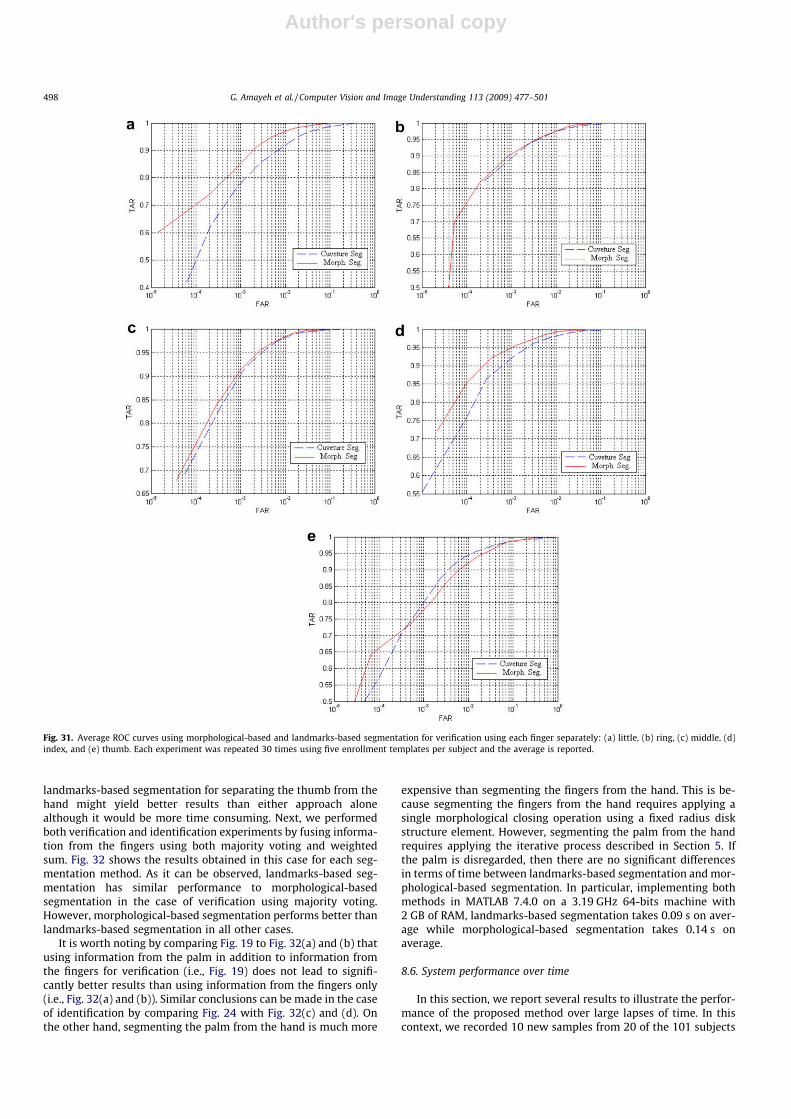
Author's personal copy
landmarks-based segmentation for separating the thumb from thehand might yield better results than either approach alonealthough it would be more time consuming. Next, we performedboth verification and identification experiments by fusing informa-tion from the fingers using both majority voting and weightedsum. Fig. 32 shows the results obtained in this case for each seg-mentation method. As it can be observed, landmarks-based seg-mentation has similar performance to morphological-basedsegmentation in the case of verification using majority voting.However, morphological-based segmentation performs better thanlandmarks-based segmentation in all other cases.
It is worth noting by comparing Fig. 19 to Fig. 32(a) and (b) thatusing information from the palm in addition to information fromthe fingers for verification (i.e., Fig. 19) does not lead to signifi-cantly better results than using information from the fingers only(i.e., Fig. 32(a) and (b)). Similar conclusions can be made in the caseof identification by comparing Fig. 24 with Fig. 32(c) and (d). Onthe other hand, segmenting the palm from the hand is much more
expensive than segmenting the fingers from the hand. This is be-cause segmenting the fingers from the hand requires applying asingle morphological closing operation using a fixed radius diskstructure element. However, segmenting the palm from the handrequires applying the iterative process described in Section 5. Ifthe palm is disregarded, then there are no significant differencesin terms of time between landmarks-based segmentation and mor-phological-based segmentation. In particular, implementing bothmethods in MATLAB 7.4.0 on a 3.19 GHz 64-bits machine with2 GB of RAM, landmarks-based segmentation takes 0.09 s on aver-age while morphological-based segmentation takes 0.14 s onaverage.
8.6. System performance over time
In this section, we report several results to illustrate the perfor-mance of the proposed method over large lapses of time. In thiscontext, we recorded 10 new samples from 20 of the 101 subjects
Fig. 31. Average ROC curves using morphological-based and landmarks-based segmentation for verification using each finger separately: (a) little, (b) ring, (c) middle, (d)index, and (e) thumb. Each experiment was repeated 30 times using five enrollment templates per subject and the average is reported.
498 G. Amayeh et al. / Computer Vision and Image Understanding 113 (2009) 477–501

Author's personal copy
after a period of 9 months (i.e., 200 images). These samples wereused to test the performance of our system when there is a sub-stantial passage time between the acquisition of the templateand test images. In a similar manner as before, we repeated eachexperiment 30 times using 3, 4, and 5 samples from our initial datacollection as enrolment templates. To keep results consistent, weused exactly the same enrolment templates in each experimentas in our previous experiments. Fig. 33(a) and (b) show the averageROC and CMC curves respectively obtained in this case. As it can beobserved by comparing Fig. 33(a) with Fig. 18(d), and Fig. 33(b)with Fig. 23(b) there is a small deterioration in system perfor-mance over time, however, this is quite reasonable and acceptable.
To further test the performance of our method on time lapse, weperformed more experiments using a publicly available hand data-
base provided by University of Notre Dame [54]. This database wascreated by collecting data on three different sessions. In the firstsession, two images from 132 subjects were collected. In the sec-ond session, which was conducted a week later, three images werecollected from the same 132 subjects. The third session, which wasconducted 15 weeks later from the second session, three imageswere collected from 177 subjects of which 86 had participated inthe first two data collections [54]. The database contains bothrange and color images, each being 640� 480 in size.
In our experiments, we used the color images of the same 86subjects who participated in all three sessions. To extract the handsilhouette, we used the same algorithm described in [54]. However,since lighting was not uniform in all images, some areas of the palmhave low contrast. As a result, the hand silhouette was defected
Fig. 32. Comparison of morphological-based and landmarks-based segmentation using different fusion strategies: (a) verification using weighted sum, (b) verification usingmajority voting, (c) identification using weighted sum, and (d) identification using majority voting. Each experiment was repeated 30 times using five enrollment templatesper subject and the average is reported.
Fig. 33. Effect of time lapse: (a) average ROC curves for verification based on decision-level fusion (majority voting) using 3, 4, and 5 templates per subject; (b) average CMCcurves for identification based on score-level fusion (weighted sum) using 3, 4, and 5 templates per subject. The experiment was performed 30 times using the sameenrollment templates as in the previous experiments. For testing, we used 200 images from 20 of the 101 subjects, taken 9 months later.
G. Amayeh et al. / Computer Vision and Image Understanding 113 (2009) 477–501 499
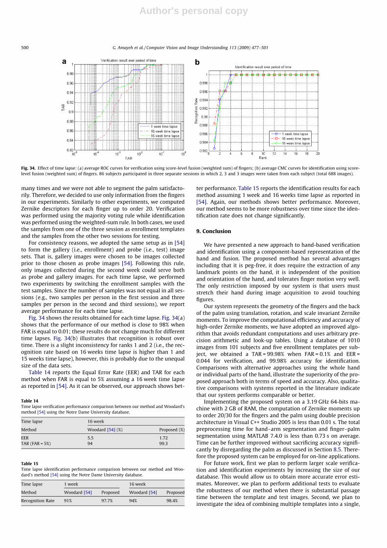
Author's personal copy
many times and we were not able to segment the palm satisfacto-rily. Therefore, we decided to use only information from the fingersin our experiments. Similarly to other experiments, we computedZernike descriptors for each finger up to order 20. Verificationwas performed using the majority voting rule while identificationwas performed using the weighted-sum rule. In both cases, we usedthe samples from one of the three session as enrollment templatesand the samples from the other two sessions for testing.
For consistency reasons, we adopted the same setup as in [54]to form the gallery (i.e., enrollment) and probe (i.e., test) imagesets. That is, gallery images were chosen to be images collectedprior to those chosen as probe images [54]. Following this rule,only images collected during the second week could serve bothas probe and gallery images. For each time lapse, we performedtwo experiments by switching the enrollment samples with thetest samples. Since the number of samples was not equal in all ses-sions (e.g., two samples per person in the first session and threesamples per person in the second and third sessions), we reportaverage performance for each time lapse.
Fig. 34 shows the results obtained for each time lapse. Fig. 34(a)shows that the performance of our method is close to 98% whenFAR is equal to 0.01; these results do not change much for differenttime lapses. Fig. 34(b) illustrates that recognition is robust overtime. There is a slight inconsistency for ranks 1 and 2 (i.e., the rec-ognition rate based on 16 weeks time lapse is higher than 1 and15 weeks time lapse), however, this is probably due to the unequalsize of the data sets.
Table 14 reports the Equal Error Rate (EER) and TAR for eachmethod when FAR is equal to 5% assuming a 16 week time lapseas reported in [54]. As it can be observed, our approach shows bet-
ter performance. Table 15 reports the identification results for eachmethod assuming 1 week and 16 weeks time lapse as reported in[54]. Again, our methods shows better performance. Moreover,our method seems to be more robustness over time since the iden-tification rate does not change significantly.
9. Conclusion
We have presented a new approach to hand-based verificationand identification using a component-based representation of thehand and fusion. The proposed method has several advantagesincluding that it is peg-free, it does require the extraction of anylandmark points on the hand, it is independent of the positionand orientation of the hand, and tolerates finger motion very well.The only restriction imposed by our system is that users muststretch their hand during image acquisition to avoid touchingfigures.
Our system represents the geometry of the fingers and the backof the palm using translation, rotation, and scale invariant Zernikemoments. To improve the computational efficiency and accuracy ofhigh-order Zernike moments, we have adopted an improved algo-rithm that avoids redundant computations and uses arbitrary pre-cision arithmetic and look-up tables. Using a database of 1010images from 101 subjects and five enrollment templates per sub-ject, we obtained a TAR = 99.98% when FAR = 0.1% and EER =0.044 for verification, and 99.98% accuracy for identification.Comparisons with alternative approaches using the whole handor individual parts of the hand, illustrate the superiority of the pro-posed approach both in terms of speed and accuracy. Also, qualita-tive comparisons with systems reported in the literature indicatethat our system performs comparable or better.
Implementing the proposed system on a 3.19 GHz 64-bits ma-chine with 2 GB of RAM, the computation of Zernike moments upto order 20/30 for the fingers and the palm using double precisionarchitecture in Visual C++ Studio 2005 is less than 0.01 s. The totalpreprocessing time for hand–arm segmentation and finger–palmsegmentation using MATLAB 7.4.0 is less than 0.73 s on average.Time can be further improved without sacrificing accuracy signifi-cantly by disregarding the palm as discussed in Section 8.5. There-fore the proposed system can be employed for on-line applications.
For future work, first we plan to perform larger scale verifica-tion and identification experiments by increasing the size of ourdatabase. This would allow us to obtain more accurate error esti-mates. Moreover, we plan to perform additional tests to evaluatethe robustness of our method when there is substantial passagetime between the template and test images. Second, we plan toinvestigate the idea of combining multiple templates into a single,
Fig. 34. Effect of time lapse: (a) average ROC curves for verification using score-level fusion (weighted sum) of fingers; (b) average CMC curves for identification using score-level fusion (weighted sum) of fingers. 86 subjects participated in three separate sessions in which 2, 3 and 3 images were taken from each subject (total 688 images).
Table 14Time lapse verification performance comparison between our method and Woodard’smethod [54] using the Notre Dame University database.
Time lapse 16 week
Method Woodard [54] (%) Proposed (%)
EER 5.5 1.72TAR (FAR = 5%) 94 99.3
Table 15Time lapse identification performance comparison between our method and Woo-dard’s method [54] using the Notre Dame University database.
Time lapse 1 week 16 week
Method Woodard [54] Proposed Woodard [54] Proposed
Recognition Rate 91% 97.7% 94% 98.4%
500 G. Amayeh et al. / Computer Vision and Image Understanding 113 (2009) 477–501

Author's personal copy
‘‘super-template”, in order to build more accurate models for eachsubject and reduce storage requirements. Third, we plan to inves-tigate feature selection schemes in order to reduce the dimension-ality of the feature vectors without sacrificing discriminationpower. This would also reduce time requirements since we wouldneed to compute a small number of Zernike moments only. Finally,we plan to perform additional comparisons with other methods inthe literature using the same database.
Acknowledgements
This research was supported in part by NSF under EPSCoR RING-TRUE III Grant No. 0447416 and in part by NASA under EPSCoRGrant No. NCC5-583.
References
[1] Biometrics market and industry report 2004–2008. Available from: <http://www.biometricgroup.com/reports/public/market_report.html>.
[2] A.K. Jain, A. Ross, S. Pankanti, A prototype hand geometry-based verificationsystem, in: Proceedings of the 2nd International Conference on Audio- andVideo-based Personal Authentication (AVBPA), Washington, USA, March 1999,pp. 166–171.
[3] A. Ross, A.K. Jain, Information fusion in biometrics, Pattern Recognition Letters24 (13) (2003) 2115–2125.
[4] A. Kumar, D.C.M. Wong, H.C. Shen, A.K. Jain, Personal verification usingpalmprint and hand geometry biometric, in: Time-Varying Image Processingand Moving Object Recognition, Guildford, UK, June 2003, pp. 668–678.
[5] F. Zernike, Beugungstheorie des schneidenverfahrens und seiner verbessertenform, derphasenkontrastmethode, Physica 1 (1934) 689–704.
[6] C. Teh, R. Chin, On image analysis by the methods of moments, IEEETransactions on Image Analysis and Machine Intelligence 10 (4) (1988) 496–513.
[7] J. Noh, K. Rhee, Palmprint identification algorithm using hu invariant momentsand otsu binarization, in: ACIS International Conference on Computer andInformation Science, 2005.
[8] Y.H. Pang, A. Teoh, D. Ngo, H.F. San, Palmprint verification with moments,Journal of WSCG 12 (2) (2004) 325–332.
[9] M.R. Teague, Image analysis via the general theory of moments, Journal of theOptical Society of America 70 (1980) 920–930.
[10] G. Amayeh, A. Erol, G. Bebis, M. Nicolescu, Accurate and efficient computationof high order zernike moments, in: First International Symposium on VisualComputing, (ISVC 2005), Lake Tahoe, NV, December 5–7, 2005, pp. 462–469.
[11] A. Ross, R. Govindarajan, Feature level fusion using hand and face biometrics,in: SPIE Conference on Biometrics Technology for Human Identification, vol.5779, No. 2, March 2005, pp. 196–204.
[12] A. Kumar, D. Zhang, Personal recognition using hand shape and texture, IEEETransactions on Image Processing 15 (2006) 2454–2461.
[13] M. Cheung, M. Mak, S. Kung, A two level fusion approach to multimodalbiometrics verification, in: IEEE International Conference on Acoustics, Speech,and Signal Processing (ICASSP’05), vol. 5, 18–23 March 2005, pp. 485–488.
[14] C. Jiang, G. Su, Information fusion in face and fingerprint identity verificationsystem, in: The Third International Conference on Machine Learning andCybernetics, 26–29 August 2004, pp. 3529–3535.
[15] S. Agarwal, A. Awan, D. Roth, Learning to detect objects in images via a sparse,part-based representation, IEEE Transactions on Pattern Analysis and MachineIntelligence 26 (11) (2004) 1475–1490.
[16] H. Schneiderman, T. Kanade, Object detection using the statistics of parts,International Journal of Computer Vision 56 (3) (2004) 151–177.
[17] B. Heisele, Visual object recognition with supervised learning, IEEE IntelligentSystems (2003) 38–42.
[18] A. Mohan, C. Papageorgiou, T. Poggio, Example-based object detection inimages by components, IEEE Transactions on Pattern Analysis and MachineIntelligence 23 (4) (2001) 349–361.
[19] R. Duda, P. Hart, D. Stork, Pattern Classification. second ed., 2000, 640p.[20] G. Amayeh and G. Bebis, A. Erol, M. Nicolescu, Peg-free hand shape verification
using high order zernike moments, in: IEEE Workshop on Multi-modalBiometrics, (in conjunction with CVPR 2006), New York City, NY, June 17–18, 2006.
[21] G. Amayeh, G. Bebis, A. Erol, M. Nicolescu, A new approach to hand-basedauthentication, in: SPIE Defense and Security Symposium: BiometricTechnology for Human Identification IV, Orlando, FL, April 9–10, 2007.
[22] G. Amayeh, G. Bebis, A. Erol, M. Nicolescu, A component-based approach tohand verification, in: IEEE Workshop on Biometrics,(in conjunction with CVPR2007), Minneapolis, MN, June 18, 2007.
[23] A.K. Jain, R. Bolle, S. Pankanti, Biometrics: Personal Identification in NetworkedSociety, Kluwer Academic Publishers, 1999.
[24] R. Sanchez-Reillo, Hand geometry pattern recognition through gaussianmixture modelling, in: Proceedings of the 15th International Conference onPattern Recognition (ICPR’00), vol. 2, 2000, pp. 937–940.
[25] A.K. Jain, N. Duta, Deformable matching of hand shapes for verification, in:Proc. IEEE International Conference on Image processing, Kobe, Japan, October1999, pp. 857–861.
[26] W. Xiong, C. Xu, S.H. Ong, Peg-free human hand shape analysis andrecognition, in: Proceedings of the IEEE International Conference onAcoustics, Speech, and Signal Processing (ICASSP’05), vol. 2, March 18–232005, pp. 77–80.
[27] L. Wong, P. Shi, Peg-free hand geometry recognition using hierarchicalgeometry and shape matching, in: IAPR Workshop on Machine VisionApplications, Nara, Japan, 2002, pp. 281–284.
[28] S. Ribaric, D. Ribaric, N. Pavesic, Multimodal biometric user-identificationsystem for network-based applications, in: IEE Proceedings on Vision Imageand Signal Processing, vol. 150, No. 6, December 2003, pp. 409–416.
[29] Y. Bulatov, S. Jambawalikar, P. Kumar, S. Sethia, Hand recognition usinggeometric classifiers, in: ICBA’04, Hong Kong, China, July 2004, pp. 753–759.
[30] A.K. Jain, N. Duta, Deformable matching of hand shapes for verification, inProceedings of the IEEE International Conference on Image Processing, Kobe,Japan, October 1999, pp. 857–861.
[31] Y.L. Ma, F. Pollick, W.T. Hewitt, Using b-spline curves for hand recognition, in:Proceedings of the 17th International Conference on Pattern Recognition(ICPR’04), vol. 3, August 2004, pp. 274–277.
[32] A. Kumar, D.C.M. Wong, H.C. Shen, A.K. Jain, Personal verification usingpalmprint and hand geometry biometric, in: Time-Varying Image Processingand Moving Object Recognition, Guildford, UK, June 2003, pp. 668–678.
[33] E. Yoruk, E. Konukoglu, B. Sankur, J. Darbon, Shape-based hand recognition,IEEE Transactions on Image Processing 15 (7) (2006) 1803–1815.
[34] D.L. Woodard and P.J. Flynn, Personal identification utilizing finger surfacefeatures, CVPR, San Diego, CA, USA, 2005.
[35] Y.L. Lay, Hand shape recognition, Optics and Laser Technology 32 (2000) 1–5.[36] R. Sanchez-Reillo, C. Sanchez-Avila, A. Gonzalez-Marcos, Biometric
identification through hand geometry measurements, IEEE Transactions onPattern Analysis and Machine Intelligence 22 (10) (2000) 1168–1171.
[37] R. Sanchez-Reillo, Hand geometry pattern recognition through gaussianmixture modelling, in: Proceedings of the 15th International Conference onPattern Recognition (ICPR’00), vol. 2, 2000, pp. 937–940.
[38] R. Mukundan, K.R. Ramakrishnan, Fast computation of legendre and zernikemoments, Pattern Recognition 28 (9) (1995) 1433–1442.
[39] S.O. Belkasim, M. Ahmadi, M. Shridhar, Efficient algorithm for fastcomputation of zernike moments, in: IEEE 39th Midwest Symposium onCircuits and Systems, vol. 3, August 1996, pp. 1401–1404.
[40] J. Gu, H.Z. Shua, C. Toumoulinb, L.M. Luoa, A novel algorithm for fastcomputation of Zernike moments, Pattern Recognition 35 (12) (2002) 2905–2911.
[41] A. Khotanzad, Y.H. Hong, Invariant image recognition by zernike moments,IEEE Transactions on Pattern Analysis and Machine Intelligence 12 (1990)489–498.
[42] R.C. Gonzalez, R.E. Woods, Digital Image Processing, Prentice-Hall, 2002.[43] R.M. Haralock, L.G. Shapiro, Computer and Robot Vision, Addison-Wesley
Longman Publishing Co., Inc., Boston, MA, USA, 1991.[44] S.X. Liao, M. Pawlak, On the accuracy of zernike moments for image analysis,
IEEE Transactions on Pattern Analysis and Machine Intelligence 20 (12) (1998)1358–1364.
[45] R.O. Duda, P.E. Hart, D.G. Stork, Pattern Classification, John-Wiley, 2001.[46] Z. Sun, G. Bebis, R. Miller, Object detection using feature subset selection,
Pattern Recognition 37 (2004) 2165–2176.[47] L. Kotoulas, I. Andreadis, Real-time computation of zernike moments, IEEE
Transactions on Circuits and Systems for Video Technology 15 (6) (2005) 801–809.
[48] O. Aubreton, L.F.C. Lew Yan Voon, B. Lamalle, G. Cathebras, F. Moniot, A cmosretina for zernike moments estimation, in: SPIE Conference on ElectronicImaging, vol. 5677, 2005, pp. 119–128.
[49] J. Kittler, M. Hatef, R. Duin, J. Matas, On combining classifiers, IEEETransactions on Patterns Analysis and Machine Intelligence 20 (1998) 226–239.
[50] J. Phillips, H. Moon, S. Rizvi, P. Rauss, The feret evaluation methodology forface-recognition algorithms, IEEE Transactions on Patterns Analysis andMachine Intelligence 22 (10) (2000) 1090–1104.
[51] E. Yoruk, E. Konukoglu, B. Sankur, J. Darbon, Shape-based hand recognition,IEEE Transactions on Image Processing 15 (7) (2006) 1803–1815.
[52] F. Mokhtarian, A. Mackworth, A theory of multiscale, curvature-based shaperepresentation for planar curves, IEEE Transactions on Pattern Analysis andMachine Intelligence 14 (8) (1992) 789–805.
[53] G. Bebis, G. Papadourakis, S. Orphanoudakis, Curvature scale space drivenobject recognition with an indexing scheme based on artificial neuralnetworks, Pattern Recognition 32 (7) (1999) 1175–1201.
[54] D.L. Woodard, P.J. Flynn, Finger surface as a biometric identifier, ComputerVision and Image Understanding 100 (2005) 357–384.
[55] Cenker Oden, Aytul Ercil, Burak Buke, Combining implicit polynomials andgeometric features for hand recognition, Pattern Recognition Letters 24 (13)(2003) 2145–2152.
G. Amayeh et al. / Computer Vision and Image Understanding 113 (2009) 477–501 501