hand biometrics - busimsankur/sankurfolder/hand_biometry_in_print.pdf · hand biometrics erdem...
TRANSCRIPT

Hand biometrics
Erdem Yoruk, Helin Dutagaci, Bulent Sankur *
Electrical and Electronic Engineering Department, Bogazici University, Bebek, Istanbul, Turkey
Received 4 December 2004; received in revised form 20 December 2005; accepted 31 January 2006
Abstract
The potential of hand shape and hand texture-based biometry is investigated and algorithms are developed. Feature extraction stage is preceded
by meticulous registration of the deformable shape of the hand. Alternative features addressing hand shape and hand texture are compared.
Independent component analysis features prove to be the best performing in the identification and verification tasks. It is shown that hand
biometric devices can be built that perform reliably for a population of at least 1000.
q 2006 Elsevier B.V. All rights reserved.
Keywords: Biometry; Identification and verification; Principal component analysis and independent component analysis; Registration for deformable shapes;
Distance transform
1. Introduction
Among a number of biometric techniques that are used for
frequent human identification tasks, hand shape and hand
shape-based biometry is an emerging new technique, with
certain advantages over the more established competitor
techniques. First, human hand data acquisition is less
cumbersome, user-friendlier. Furthermore, it is much less
susceptible to intrinsic variations and environmental artifacts
[1]. In contrast, fingerprint acquisition is usually associated
with criminal identification, and is therefore psychologically
disturbing. Iris and retinal scans require sophisticated,
expensive and more intrusive acquisition systems. Though
these alternative techniques have considerable discriminative
power, users may not be too keen employ them for daily access
control or verification in e-commerce applications. Systems
relying on human face or voice identification are more
established at present and seem user-friendlier, but suffer
from intra-class variations and background/noise elimination
problems. Pose, expression and illumination artifacts affect
face recognition, while voice recognition is prey to health and/
or emotional state of the speaker. However, both face and voice
recognition still remain as very active research areas. All in all,
0262-8856/$ - see front matter q 2006 Elsevier B.V. All rights reserved.
doi:10.1016/j.imavis.2006.01.020
* Corresponding author. Tel.: C90 212 359 6414; fax: C90 212 287 2465.
E-mail addresses: [email protected] (E. Yoruk), dutagach@boun.
edu.tr (H. Dutagaci), [email protected] (B. Sankur).
hand-based identification/verification systems provide an
attractive and growing alternative biometric scheme [2].
There have been a number of previous studies investigating
hand-based biometry. Some of these schemes rely solely on
geometrical features, others use hand silhouette shape with or
without geometric features, still others use extracted palm print
lines, and finally there are approaches that combine palm lines
with hand shape.
Schemes that utilize geometrical features of the hand focus
on such characteristics as widths of fingers at articulations,
finger and palm lengths, finger deviations and the angles of the
inter-finger valleys with the horizontal [3–6]. The number of
features varied typically, in the range of 20–30, and the
acquisition styles also differed, in that some necessitate pegs to
position fingers while others were peg-free. These schemes
have the advantage that the features are local, and hence
accurate hand registration and normalization are not needed.
Oden et al. [7] used jointly finger shape information and
geometric features. The shape information of the individual
fingers (but not the whole hand) was extracted via implicit
polynomials and the geometric features were joined at the
feature fusion stage.
There is also increasing research on palm print-based
identification/verification systems. One challenging problem
with the palm print is the extraction of features such as line
structures from the palm print image. For that reason, most of
the proposed algorithms [8–10] require ink markings for
obtaining enhanced palm print images. On the other hand, Zhan
[8,11] uses a special scanning system to automatically extract
the palm curves from high-quality and well-aligned palm print
Image and Vision Computing 24 (2006) 483–497
www.elsevier.com/locate/imavis

E. Yoruk et al. / Image and Vision Computing 24 (2006) 483–497484
images. The verification algorithm proposed by Han et al. [12]
does not require peg or ink usage, and the palm print features.
The extracted features via Sobel and morphological operators
are used with template matching and a back-propagation neural
network to determine palm print similarity between hands. In
Kong et al. [13], 2D Gabor filters are implemented to obtain
texture information and two palm print images are compared in
terms of their hamming distance.
It is possible to use both hand geometry and palm print
information. Kumar et al. [14] have proposed an approach
based on the integration of hand geometry features to hand-
based verification. They developed a system where the palm
gray level information is fused with the geometrical features of
the hand.
In this work, we propose a novel hand-based biometric
system. The originality of our work resides in two aspects. Our
first contribution is the development of a very accurate hand
normalization scheme, whereby hand images captured in
arbitrary postures are brought to standard finger orientations
and overall pose. Such a hand normalization allows the
consideration of global features and increases the capacity of
the system significantly, i.e. the size of the subject population
correctly identified. As a second contribution, we consider
global appearance-based features of the hands for identification
and verification tasks. Two of these features are data-driven
statistical features, such as principal component analysis and
independent component analysis features, and two of them are
general features, such as axial radial transform and distance
transform. We extract these features either from pure shape
information or from the hand texture plus shape information,
and we investigate their biometric impact. Finally, the size of
the enrollment in our work exceeds the populations used in the
literature by almost an order of magnitudes. As a byproduct, we
have analyzed the similarities between the right and left hands
of people, since we capture both of them.
The paper is organized as follows. In Section 2, the
segmentation of hand images from its background and the
various normalization steps for the deformable hand images are
given. Section 3 describes the features we extract from the
normalized hand silhouettes and textures. The experimental
set-up and the classification results are discussed in Section 4
and conclusions are drawn in Section 5.
2. Hand normalization
The normalization of hands is of paramount importance for
any verification and identification task. This is because the
difference between appearance-based features of a hand in
different postures, as in Fig. 1, by far exceeds the difference
between those features between hands belonging to different
subjects. The normalization task involves several consecutive
processing steps, namely, segmentation of the hand image from
the background, hand rotation and translation, finding the
finger axes and tips, removal of ring artifacts, completion of the
wrist, estimation of finger pivots (metacarpal–phalanx joints),
rotation and translation of fingers to standard orientations.
These steps are pictured in the block diagram in Fig. 2 and are
described below.
2.1. Hand segmentation
Image capturing devices (scanner or digital camera) yield
basically a two-class image, with hand texture in the
foreground and a darker background. We start with the two-
class K-means clustering algorithm, followed by morphologi-
cal operators to fill in holes and remove isolated foreground
debris [15]. Thus, size filtering is applied on the connected
components of the image to remove spurious components in
the background, and then repeat this operation on the video
reverse image to remove background holes in the hand region.
These two steps satisfactorily separate and extract the hand
from the background. Finally, we apply a ‘ring artifact
removal’ algorithm [16] to correct for any straights or
isthmuses caused by the presence of rings. The outcome is a
binary image corresponding to the silhouette of the hand
(Fig. 2a–b).
2.2. Initial hand registration
Hand images are first subjected to a global rotation and
translation. This coarse registration involves translation of the
centroid of the binary hand mass and its rotation in the direction
of the larger eigenvector of the inertia matrix [17]. The inertia
matrix can be envisioned as an ellipse fitted to the connected
component of the hand object, where the larger eigenvalue
determines the hand orientation and corresponds to the major axis
of the ellipse. The sign ambiguity in the resulting eigenvector, i.e.
the problem of the sense of rotation, is resolved by considering
the relative shift in the centroid of the eroded hand image, since
loss of mass would be more rapid in the portion of fingers.
2.3. Finger tips and valleys
Hand extremities, i.e. the finger tips and the finger valleys
form fiduciary landmarks. A robust method to extract these
contour extremities consists in computing the radial distances
with respect to a reference point around the wrist region. This
reference point can be taken as the first intersection point of the
major axis (the larger eigenvector of the inertial matrix) with
the wrist line. The resulting sequence of radial distances yields
minima and maxima corresponding to the sought extremum
points. Since the resulting extrema are very stable, the
definition of the five maxima (fingertips) and of the four
minima are not easily affected by segmentation artifacts on the
contour. The radial distance function and a typical hand
contour with extremities marked on it are given in Fig. 2e.
2.4. Wrist completion
The hand contours in the wrist region can be irregular and
noisy due to clothing occlusion or due to the different angles
that the forearm can make with the platen, and due to the
varying pressure exerted on the imaging device. These factors
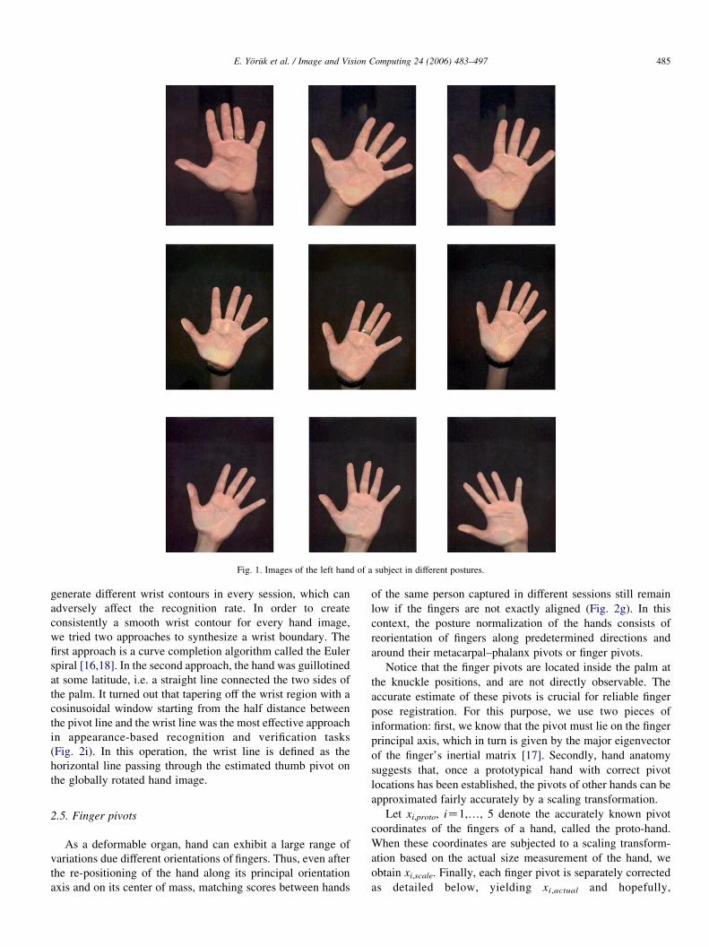
Fig. 1. Images of the left hand of a subject in different postures.
E. Yoruk et al. / Image and Vision Computing 24 (2006) 483–497 485
generate different wrist contours in every session, which can
adversely affect the recognition rate. In order to create
consistently a smooth wrist contour for every hand image,
we tried two approaches to synthesize a wrist boundary. The
first approach is a curve completion algorithm called the Euler
spiral [16,18]. In the second approach, the hand was guillotined
at some latitude, i.e. a straight line connected the two sides of
the palm. It turned out that tapering off the wrist region with a
cosinusoidal window starting from the half distance between
the pivot line and the wrist line was the most effective approach
in appearance-based recognition and verification tasks
(Fig. 2i). In this operation, the wrist line is defined as the
horizontal line passing through the estimated thumb pivot on
the globally rotated hand image.
2.5. Finger pivots
As a deformable organ, hand can exhibit a large range of
variations due different orientations of fingers. Thus, even after
the re-positioning of the hand along its principal orientation
axis and on its center of mass, matching scores between hands
of the same person captured in different sessions still remain
low if the fingers are not exactly aligned (Fig. 2g). In this
context, the posture normalization of the hands consists of
reorientation of fingers along predetermined directions and
around their metacarpal–phalanx pivots or finger pivots.
Notice that the finger pivots are located inside the palm at
the knuckle positions, and are not directly observable. The
accurate estimate of these pivots is crucial for reliable finger
pose registration. For this purpose, we use two pieces of
information: first, we know that the pivot must lie on the finger
principal axis, which in turn is given by the major eigenvector
of the finger’s inertial matrix [17]. Secondly, hand anatomy
suggests that, once a prototypical hand with correct pivot
locations has been established, the pivots of other hands can be
approximated fairly accurately by a scaling transformation.
Let xi,proto, iZ1,., 5 denote the accurately known pivot
coordinates of the fingers of a hand, called the proto-hand.
When these coordinates are subjected to a scaling transform-
ation based on the actual size measurement of the hand, we
obtain xi,scale. Finally, each finger pivot is separately corrected
as detailed below, yielding xi,actual and hopefully,
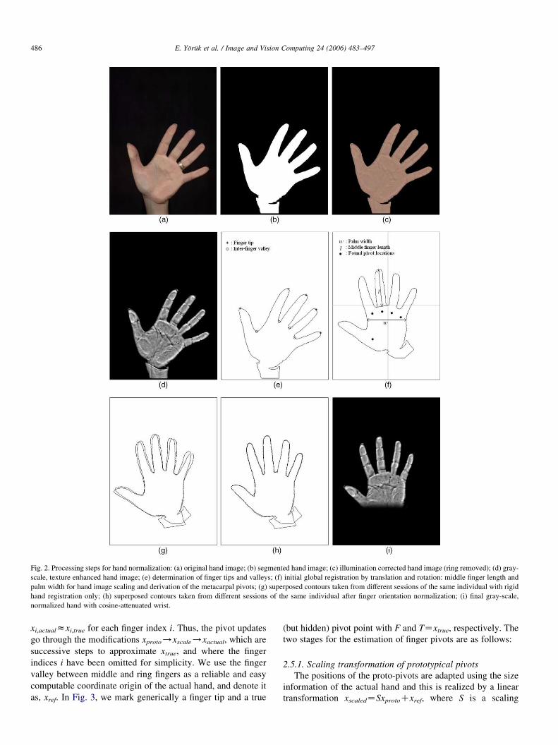
Fig. 2. Processing steps for hand normalization: (a) original hand image; (b) segmented hand image; (c) illumination corrected hand image (ring removed); (d) gray-
scale, texture enhanced hand image; (e) determination of finger tips and valleys; (f) initial global registration by translation and rotation: middle finger length and
palm width for hand image scaling and derivation of the metacarpal pivots; (g) superposed contours taken from different sessions of the same individual with rigid
hand registration only; (h) superposed contours taken from different sessions of the same individual after finger orientation normalization; (i) final gray-scale,
normalized hand with cosine-attenuated wrist.
E. Yoruk et al. / Image and Vision Computing 24 (2006) 483–497486
xi,actualzxi,true for each finger index i. Thus, the pivot updates
go through the modifications xproto/xscale/xactual, which are
successive steps to approximate xtrue, and where the finger
indices i have been omitted for simplicity. We use the finger
valley between middle and ring fingers as a reliable and easy
computable coordinate origin of the actual hand, and denote it
as, xref. In Fig. 3, we mark generically a finger tip and a true
(but hidden) pivot point with F and TZxtrue, respectively. The
two stages for the estimation of finger pivots are as follows:
2.5.1. Scaling transformation of prototypical pivots
The positions of the proto-pivots are adapted using the size
information of the actual hand and this is realized by a linear
transformation xscaledZSxprotoCxref, where S is a scaling
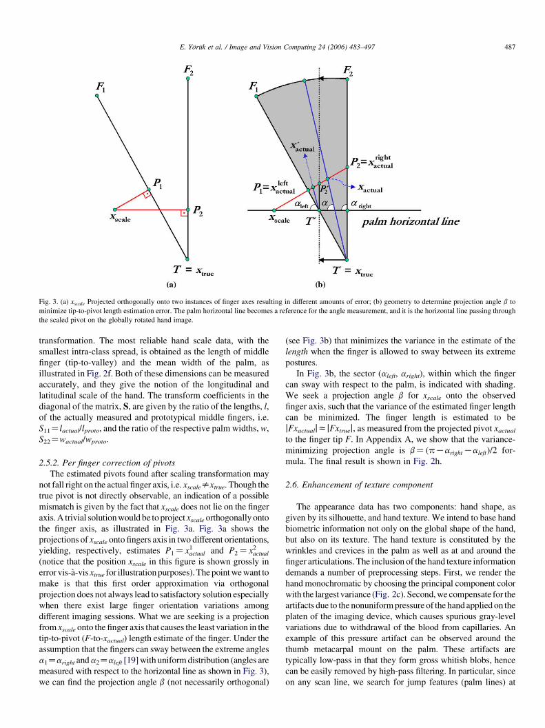
Fig. 3. (a) xscale Projected orthogonally onto two instances of finger axes resulting in different amounts of error; (b) geometry to determine projection angle b to
minimize tip-to-pivot length estimation error. The palm horizontal line becomes a reference for the angle measurement, and it is the horizontal line passing through
the scaled pivot on the globally rotated hand image.
E. Yoruk et al. / Image and Vision Computing 24 (2006) 483–497 487
transformation. The most reliable hand scale data, with the
smallest intra-class spread, is obtained as the length of middle
finger (tip-to-valley) and the mean width of the palm, as
illustrated in Fig. 2f. Both of these dimensions can be measured
accurately, and they give the notion of the longitudinal and
latitudinal scale of the hand. The transform coefficients in the
diagonal of the matrix, S, are given by the ratio of the lengths, l,
of the actually measured and prototypical middle fingers, i.e.
S11Zlactual/lproto, and the ratio of the respective palm widths, w,
S22Zwactual/wproto.
2.5.2. Per finger correction of pivots
The estimated pivots found after scaling transformation may
not fall right on the actual finger axis, i.e. xscalesxtrue. Though the
true pivot is not directly observable, an indication of a possible
mismatch is given by the fact that xscale does not lie on the finger
axis. A trivial solution would be to project xscale orthogonally onto
the finger axis, as illustrated in Fig. 3a. Fig. 3a shows the
projections of xscale onto fingers axis in two different orientations,
yielding, respectively, estimates P1Zx1actual and P2Zx2
actual
(notice that the position xscale in this figure is shown grossly in
error vis-a-vis xtrue for illustration purposes). The point we want to
make is that this first order approximation via orthogonal
projection does not always lead to satisfactory solution especially
when there exist large finger orientation variations among
different imaging sessions. What we are seeking is a projection
from xscale onto the finger axis that causes the least variation in the
tip-to-pivot (F-to-xactual) length estimate of the finger. Under the
assumption that the fingers can sway between the extreme angles
a1Zaright anda2Zaleft [19] with uniform distribution (angles are
measured with respect to the horizontal line as shown in Fig. 3),
we can find the projection angle b (not necessarily orthogonal)
(see Fig. 3b) that minimizes the variance in the estimate of the
length when the finger is allowed to sway between its extreme
postures.
In Fig. 3b, the sector (aleft, aright), within which the finger
can sway with respect to the palm, is indicated with shading.
We seek a projection angle b for xscale onto the observed
finger axis, such that the variance of the estimated finger length
can be minimized. The finger length is estimated to be
jFxactualjzjFxtruej, as measured from the projected pivot xactualto the finger tip F. In Appendix A, we show that the variance-
minimizing projection angle is bZ ðpKarightKaleftÞ=2 for-
mula. The final result is shown in Fig. 2h.
2.6. Enhancement of texture component
The appearance data has two components: hand shape, as
given by its silhouette, and hand texture. We intend to base hand
biometric information not only on the global shape of the hand,
but also on its texture. The hand texture is constituted by the
wrinkles and crevices in the palm as well as at and around the
finger articulations. The inclusion of the hand texture information
demands a number of preprocessing steps. First, we render the
hand monochromatic by choosing the principal component color
with the largest variance (Fig. 2c). Second, we compensate for the
artifacts due to the nonuniform pressure of the hand applied on the
platen of the imaging device, which causes spurious gray-level
variations due to withdrawal of the blood from capillaries. An
example of this pressure artifact can be observed around the
thumb metacarpal mount on the palm. These artifacts are
typically low-pass in that they form gross whitish blobs, hence
can be easily removed by high-pass filtering. In particular, since
on any scan line, we search for jump features (palm lines) at
E. Yoruk et al. / Image and Vision Computing 24 (2006) 483–497488
relatively higher frequencies, we can extract them by high-pass
filtering (Fig. 2c and d). The image was smoothed with a Gaussian
kernel (kernel window size is 20!20 and filter aperture, standard
deviation of Gaussian, is sZ5) and subtracted from the original
image. Thus, these two steps of choosing principal component
color and then its high-pass filtering constitute the color
normalization of the hand.
2.7. Texture blending with finger registration
If texture is to be used as a discriminating feature, one must
compensate for the plastic deformation of the knuckle region of
the palm ensuing from each finger’s rotation around its
metacarpal joint, the xactual pivot discussed in Section 2.5. In
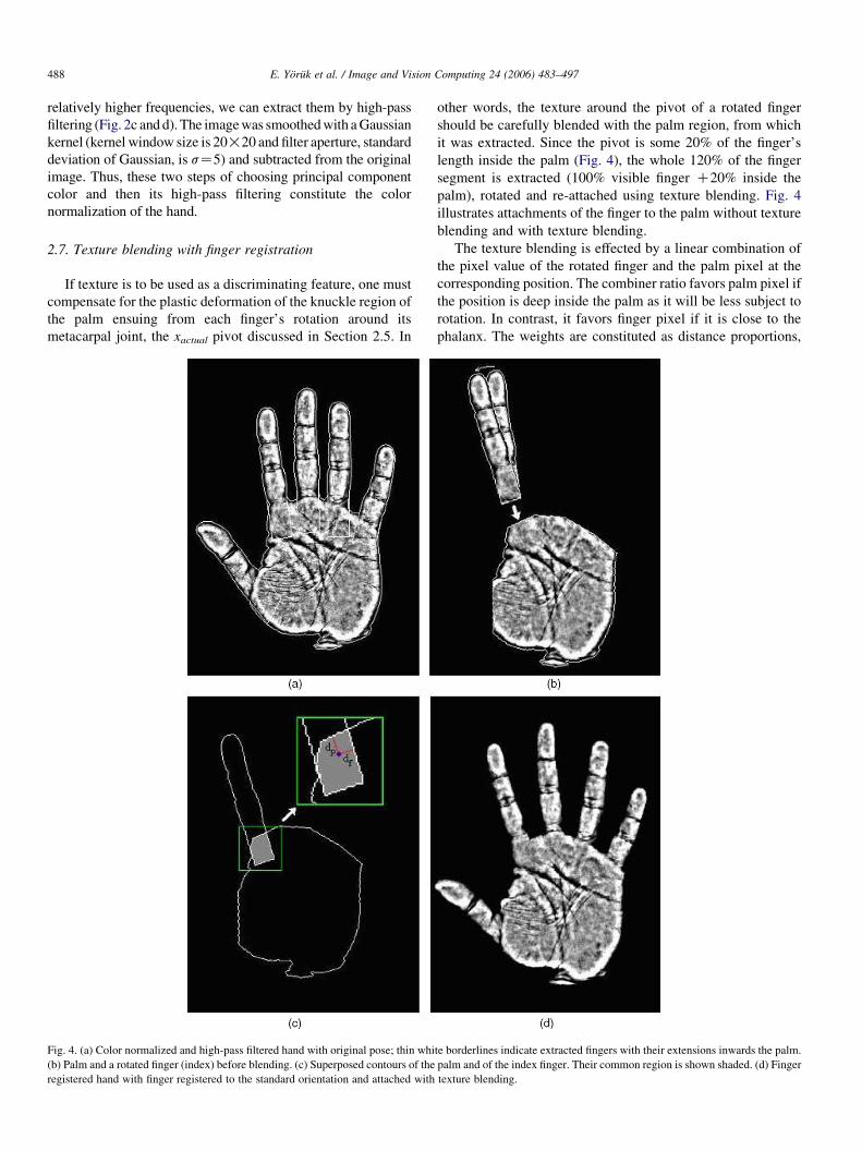
Fig. 4. (a) Color normalized and high-pass filtered hand with original pose; thin whi
(b) Palm and a rotated finger (index) before blending. (c) Superposed contours of the
registered hand with finger registered to the standard orientation and attached with
other words, the texture around the pivot of a rotated finger
should be carefully blended with the palm region, from which
it was extracted. Since the pivot is some 20% of the finger’s
length inside the palm (Fig. 4), the whole 120% of the finger
segment is extracted (100% visible finger C20% inside the
palm), rotated and re-attached using texture blending. Fig. 4
illustrates attachments of the finger to the palm without texture
blending and with texture blending.
The texture blending is effected by a linear combination of
the pixel value of the rotated finger and the palm pixel at the
corresponding position. The combiner ratio favors palm pixel if
the position is deep inside the palm as it will be less subject to
rotation. In contrast, it favors finger pixel if it is close to the
phalanx. The weights are constituted as distance proportions,
te borderlines indicate extracted fingers with their extensions inwards the palm.
palm and of the index finger. Their common region is shown shaded. (d) Finger
texture blending.

E. Yoruk et al. / Image and Vision Computing 24 (2006) 483–497 489
where the distances are the corresponding closest distances to
the boundaries (geometry illustrated in Fig. 4). A pixel
position, (i,j), common to both finger and palm regions, has
the blended intensity
Iblendði;jÞZwfingerði;jÞIfingerði;jÞCwpalmði;jÞIpalmði;jÞ
where the weights are defined as
wfingerði;jÞZdfingerði;jÞ
dfingerði;jÞCdpalmði;jÞand
wpalmði;jÞZdpalmði;jÞ
dfingerði;jÞCdpalmði;jÞ
such that dfinger(i,j) and dpalm(i,j) are the closest distances of
(i,j)th pixel to the boundary of the finger and palm segments,
respectively (see inset in Fig. 4).
Fig. 5. (a) Various hands in the database, some with rings. (b) The registered hand
texture. (d) The 100!100 pixel excerpt from the palm region.
In order to blend judiciously silhouette-based shape
information with the texture, we scale the texture information
with a weighting factor. In other words, we adjust the
contribution of the texture component by tuning its standard
deviation. If this tuning parameter is set to one, we have the
original hand appearance data, i.e. texture and shape (texture
after color normalization). As this parameter is reduced toward
zero, we use more of the silhouette and less of the texture.
When the tuning parameter is set to zero, we rely solely on the
silhouette data and exclude all texture information (Fig. 5).
3. Feature extraction
We have considered comparatively several features that
extract either pure shape information or shape information in
addition to the texture information. The features that apply to
s with color normalized texture. (c) Details of the central portion of the palm
E. Yoruk et al. / Image and Vision Computing 24 (2006) 483–497490
shape only are independent component analysis (ICA) features,
principal component analysis (PCA) features, axial radial
transform (ART) and distance transform (DT). In a previous
study, we had considered weighted Haussdorff distance as well,
but we have excluded it from the competition as its
performance falls short of ICA [16]. On the other hand, the
features extracting information from both shape and texture are
the ICA, PCA and ART schemes.
3.1. Principal component analysis features [20,21]
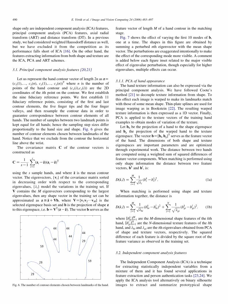
Let us represent the hand contour vector of length 2n as zZ(cx(1),., cx(n), cy(1),., cy(n))T where n is the number of
points of the hand contour and (cx(i),cy(i)) are the 2D
coordinates of the ith point on the contour. We first establish
the nine fiduciary reference points. We first establish 11
fiduciary reference points, consisting of the first and last
contour elements, the five finger tips and the four finger
valleys, and then resample the contour data in order to
guarantee correspondence between contour elements of all
hands. The number of samples between two landmark points is
kept equal for all hands; hence the sampling step sizes differ
proportionally to the hand size and shape. Fig. 6 gives the
number of contour elements chosen between landmarks of the
hand. Notice that we exclude from the contour the horizontal
line above the wrist.
The covariance matrix C of the contour vectors is
constructed as
CZ1
sK1
Xs
iZ1
ðziK~zÞðziK~zÞT
using the s sample hands, and where ~z is the mean contour
vector. The eigenvectors, {vi} of the covariance matrix sorted
in decreasing order with respect to the corresponding
eigenvalues, {li} model the variations in the training set. If
V contains the M eigenvectors corresponding to the largest
eigenvalues, then any shape vector in the training set can be
approximated as zy ~zCVb, where VZ[v1v2/vM] is the
selected eigenspace basis set and b is the projection of shape z
to this eigenspace, i.e. bZVTðzK~zÞ. The vector b serves as the
29
29
59
44
44 44
44 44
29
59
Fig. 6. The number of contour elements chosen between landmarks of the hand.
feature vector of length M of a hand contour in the matching
stage.
Fig. 7 shows the effect of varying the first 10 modes of b,
one at a time. The shapes in this figure are obtained by
summing a perturbed nth eigenvector with the mean shape
vector. The perturbations are exaggerated intentionally to make
the effect of the corresponding mode more visible. A comment
is added below each figure inset related to the major visible
effect of eigenvalue perturbation, though especially for higher
eigenvalues, multiple effects can occur.
3.1.1. PCA of hand appearance
The hand texture information can also be expressed via the
principal component analysis. We have followed Coote’s
method [21] to decouple texture information from shape. To
this effect each image is warped to make its landmarks match
with those of some mean shape. Thin-plate splines are used for
image warping as in Bookstein [22]. The resulting warped
texture information is then expressed as a 1D vector. Finally,
PCA is applied to the texture vectors of the training hand
examples to obtain modes of variation of the texture.
Let bh be the projection of a hand to the shape eigenspace
and bg the projection of the warped hand to the texture
eigenspace. The vector bZ[bh bg]T serves as the feature vector
of the hand. The dimensions of both shape and texture
eigenspaces are important parameters and are optimized
through experimental work. The distance between two hands
are computed using a weighted sum of squared differences of
feature vector components. When matching is performed using
only shape information the distance between two feature
vectors, bk and bl, is:
Dðk;lÞZXMiZ1
1ffiffiffiffili
p ðbki KbliÞ2: (1a)
When matching is performed using shape and texture
information together, the distance is
Dðk;lÞZXMiZ1
1ffiffiffiffiffiffilhi
p ðbkhiKblhiÞ2 C
XNiZ1
1ffiffiffiffiffiffilgi
p ðbkgiKblgiÞ2: (1b)
where fbkhigMiZ1 are the M-dimensional shape features of the kth
hand, fblgigNiZ1 are the N-dimensional texture features of the lth
hand, and lhi and lgi are the ith eigenvalues obtained from PCA
of shape and texture vectors, respectively. The squared
difference of each feature is divided by the square root of the
feature variance as observed in the training set.
3.2. Independent component analysis features
The Independent Component Analysis (ICA) is a technique
for extracting statistically independent variables from a
mixture of them and it has found several applications in
feature extraction and person authentication tasks [23,24]. We
apply the ICA analysis tool alternatively on binary silhouette
images to extract and summarize prototypical shape

Fig. 7. Effect of varying the weights of the first ten eigenvectors.
E. Yoruk et al. / Image and Vision Computing 24 (2006) 483–497 491
information as well as on the appearance data, which is shape
plus texture.
ICA assumes that each observed hand image, {x(k), kZ1,., K} is a mixture of a set of N unknown independent source
signals si (iZ1,., N). Here, {x(k), kZ1,., K} results from the
lexicographic ordering of the image I(i,j) in the scene, which
has a total of K pixels. Notice also that, while in the PCA
analysis we had considered images resting only within the
contours of the hand, in the case of ICA, we consider the total
scene image, consisting of its foreground and background.
With xi and si, (iZ1,., N) forming the rows of the N!K
matrices X and S, respectively, we have the following mixture
model
XZAS (2a)
SZYZWX (2b)
where A is the matrix of mixing coefficients. The ICA
algorithm finds a linear transformation SZYZWX that
minimizes the statistical dependence between the hypothesized
independent sources si, (iZ1,., N).
There exist two possible architectures for ICA, called ICA1
and ICA2 [23], depending on whether one aims for independent
basis images or for independent mixing coefficients [23]. In a
previous study [16], we found that the ICA2 architecture yielded
superior performance. In the ICA2 architecture, the superposition
coefficients are assumed to be independent, but not the basis
images. In this model, we start with the transpose of the data
matrix,XT, and reduce its large dimensionality (typically number
of pixels[number of images or K[N) via a PCA stage. Thus,
we proceed by computing the eigenvectors of the K!K
covariance matrix CZ(1/N)XTX (actually it suffices to consider
the eigenvalues of the much smaller N!N matrix XXT), we
project the data vectors onto the M (M%N) largest eigenvalues
and obtain the reduced data matrix XTreduced. The source and
mixing coefficients are then obtained using the FastICA
algorithm [25] using XTreduced in Eq. (2b). The synthesis of a
hand in the data set from the superposition of hand ‘basis images’

Fig. 8. Hand pattern synthesis using ICA2 basis functions ai, iZ1,., N denote the N basis images, while the weighting coefficients S(n,i), iZ1,., N for the hand i
are statistically independent.
E. Yoruk et al. / Image and Vision Computing 24 (2006) 483–497492
is illustrated in Fig. 8. Notice that the columns of the estimated A
matrix are the basis in of this architecture, whereas the coefficients
in the corresponding column of the estimated source matrix are
the independent weights, constituting the feature vector to be
extracted.
Similarly, whenever we want to take into account the texture
of images in the ICA formalism, we consider the image I(i,j)
(foregroundCbackground), Ishape(i,j), the binary hand silhouette
(foreground set to 1 and background to 0), and finally Itexture(i,j),
the textured image, also normalized to (0,1) interval. The image
fed into the ICA2 algorithm is Iði;jÞZ Ishapeði;jÞCaItextureði;jÞ,
with the tuning factor 0%a%1. Matching between hands are
performed by comparing ICA basis vectors, for example, the
mean-square distance between hands k and l becomes:
Dðk;lÞZPMiZ1
ðski KsliÞ2. We have observed that increasing the
texture-to-shape ratio a, from 0 to 0.2, makes the performances
significantly better as expected, since discriminative texture starts
also to play a role together with the pure shape information.
However, for a beyond 0.5, we see a certain decrease in the
overall identification rate. This can be attributed to the irrelevant
skin texture other than palm prints, which becomes to appear
more for larger values of a.
The ICA2 algorithm parameters were as follows: the
number of pixels in the hand images was KZ40,000, the
number of subjects was NZ458, and finally the number of
features, M, used in the ICA2 architecture was 200 as it yielded
the best classification result. The texture–shape power ratio
was taken as 0.2%a%0.5.
3.3. Angular radial transform features [26,27]
Angular radial transform (ART) is a complex transform
defined on the unit disk. The basis functions Vnm(r,q) are
defined in polar coordinates as a product of two separable
Fig. 9. Real parts of AR
functions along the angular and radial directions:
Vnmðr;qÞZAmðqÞRnðrÞ; where AmðqÞZ1
2pexpðjmqÞ and
RnðrÞZ1 nZ 0
2 cosðpnrÞ ns0:
(
Fig. 9 shows real parts of the ART basis functions. As can be
observed from this figure, with increasing order n, the basis
functions vary more rapidly in the radial direction, whereas the
order m expresses the variation in the angular direction.
The angular radial transform of an image f(r,q) in polar
coordinates is a set of ART coefficients {Fnm} of order n and m.
These ART coefficients can be derived as follows
Fnm Z
ð2p0
ð10
V�nmðr;qÞf ðr;qÞdr dq
and a set of N!M ART magnitude coefficients can be used as
features. Notice that, while in shape recognition, the ART
coefficients are normalized to jF00j in order to achieve scale
invariance; in our work we specifically make us of this
coefficient for discriminatory size information. After aligning
the hand images and placing them in a fixed-size image plane,
we take the center of the plane as the center of the unit disk.
Furthermore, each pixel location is converted to polar
coordinates and the radial coordinate is normalized with the
image size to have a value between 0 and 1.
We compute the ART coefficients both for the silhouette
(binary) hands as well as for the shape plus texture appearance
data, which includes palm and finger gray-level details.
T basis functions.
E. Yoruk et al. / Image and Vision Computing 24 (2006) 483–497 493
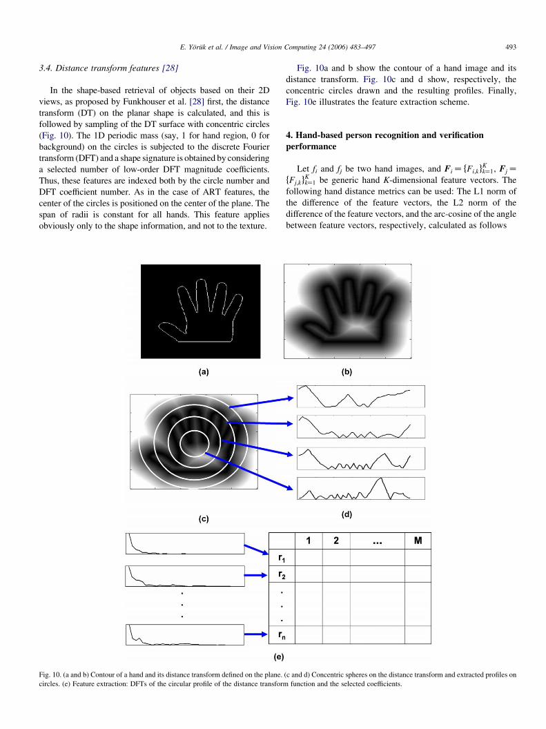
3.4. Distance transform features [28]
In the shape-based retrieval of objects based on their 2D
views, as proposed by Funkhouser et al. [28] first, the distance
transform (DT) on the planar shape is calculated, and this is
followed by sampling of the DT surface with concentric circles
(Fig. 10). The 1D periodic mass (say, 1 for hand region, 0 for
background) on the circles is subjected to the discrete Fourier
transform (DFT) and a shape signature is obtained by considering
a selected number of low-order DFT magnitude coefficients.
Thus, these features are indexed both by the circle number and
DFT coefficient number. As in the case of ART features, the
center of the circles is positioned on the center of the plane. The
span of radii is constant for all hands. This feature applies
obviously only to the shape information, and not to the texture.
Fig. 10. (a and b) Contour of a hand and its distance transform defined on the plane.
circles. (e) Feature extraction: DFTs of the circular profile of the distance transform
Fig. 10a and b show the contour of a hand image and its
distance transform. Fig. 10c and d show, respectively, the
concentric circles drawn and the resulting profiles. Finally,
Fig. 10e illustrates the feature extraction scheme.
4. Hand-based person recognition and verification
performance
Let fi and fj be two hand images, and FiZ fFi;kgKkZ1, FjZ
fFj;kgKkZ1 be generic hand K-dimensional feature vectors. The
following hand distance metrics can be used: The L1 norm of
the difference of the feature vectors, the L2 norm of the
difference of the feature vectors, and the arc-cosine of the angle
between feature vectors, respectively, calculated as follows
(c and d) Concentric spheres on the distance transform and extracted profiles on
function and the selected coefficients.

Table 1
Identification performance of feature types with different number of selected
features (population size: 458)
Feature type Number of features
40 100 200 400
ICA_shape 94.32 97.67 98.4 97.31
ICA_appearance 95.41 98.25 99.49 99.36
PCA_shape 96.01 96.97 97.19 97.16
PCA_appearance 96.27 97.91 97.99 97.91
ART_shape 94.18 95.78 95.63 95.05
ART_appearance 95.92 97.38 97.67 97.60
Distance transform 93.38 95.49 95.71 95.99
Table 2
Identification performance of feature sets with increasing population size (best
feature dimension selected for each feature type)
Feature type Population size
40 (30 Ran-
dom exper-
iments)
100 (12 Ran-
dom exper-
iments)
200 (6 Ran-
dom exper-
iments)
458
ICA_shape 99.19 99.09 98.55 98.40
ICA_appearance 99.68 99.65 99.58 99.49
PCA_shape 98.67 98.69 98.56 97.19
PCA_appearance 99.14 98.89 98.72 97.99
ART_shape 98.72 97.78 97.00 95.78
ART_appearance 99.28 98.72 98.06 97.67
DT 99.17 98.22 96.22 95.99
E. Yoruk et al. / Image and Vision Computing 24 (2006) 483–497494
d1ðfi;fjÞZXKkZ1
jFi;kKFj;kj; d2ðfi;fjÞZXKkZ1
jFi;kKFj;kj2;
dcosðfi;fjÞZ 1KFi$Fj
jjFijjjjFjjj;
where $ is the inner product notation. Thus hand distances,
whether shape-based or shape plus texture-based, are measured
in terms of some norm of their feature vectors.
In identification mode, the user does not provide any
identity claim, but the system must find out the user’s identity
from a database of enrolled users. For person identification
task, we measure the distance between the test feature vector,
Ftest and all the feature vectors Fi, iZ1,., N in the database
belonging to N different subjects. The index of the hand giving
the minimum distance is selected as the identity of the input
hand, i.e. the person i� is identified if
i�Zarg minðiÞfdðFtest;FiÞg. Notice that there could be more
than one hand image stored per person, consequently the
number of comparisons amounts to the number of subjects
times the number of images per subject.
For a person verification task, one must differentiate the
‘genuine hand’ from the ‘impostor hands’ as the user provides
her hand image in support of her claimed identity. For this
1 2 3 4 5 6 780
82
84
86
88
90
92
94
96
98
100
feature type
Iden
tific
atio
n pe
rfor
man
ce (
%)
Fig. 11. Bar graph showing the performance attainable with every feature set.
Every feature set is optimized with respect to the feature dimensions.
Maximum population size is used, i.e. 458. Gray whiskers show the region
between the best performance and average performance with each feature set.
purpose, the distances between the hand of the applicant and all
the hands in the database are calculated and the scores
compared against a threshold. As we lower the acceptance
threshold on d(Ftest, Fi), the probability of detection increases
at the risk of increased false alarm, i.e. of accepting an impostor
as a genuine.
Table 1 and Fig. 11 show the experimental identification
performance of various feature types, as the number of feature
components grows, while Table 2 gives the variation of
performance scores as the population size increases. Several
observations can be made. First, all feature types benefit from
an increase in dimensionality, as they start from a modest size
of 40. For the population size of 458, all of them seem to have a
broad peak at an around dimension 200. Second, ICA features
applied on the hand appearance data are the best among all.
This holds both in the competition between shape-only
recognition and shape-plus-texture recognition. Thirdly, as
expected, the addition of texture information improves the
recognition performance. However, the improvement remains
around 1% for the ICA and PCA features and 2% for the ART
feature. Finally, as in Table 2, the population size grows an
order of magnitude from 40 to 458 all features suffer a
performance drop ranging from 1 to 3%. The only exception is
the ICA features on appearance data, where the performance
drop is only a meager 0.2%, which again points out to the
robustness of the ICA features. These results are obtained by
averaging the performance over several randomly chosen
subsets of populations, for example, over 30 different choices
of 40-tuple subsets, etc. as shown in the first row of Table 2.
Table 3 and Fig. 12 present the hand-based verification
results. Table 3 gives the correct verification percentages as a
function of population size. The main observations are parallel
to those for the identification case, namely: (i) the slow
performance drop with increasing population size, (ii) the
superiority of the ICA features, (iii) the less than 1%
contribution of the texture component to the shape only
recognition. Notice that the verification performances seem to
increase in row 2 of Table 3. Actually, while the number of
impostors that pass through increases, the population size
increase is more rapid than the growth in the false alarm rate.
Since both right and left hands were measured, we
computed the distribution of the distance between the ICA
feature vectors between the two hands of the same person. In
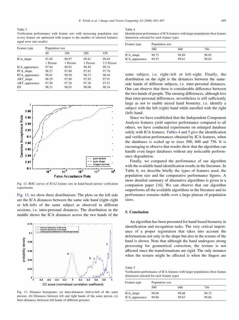
Table 3
Verification performance with feature sets with increasing population size
(every feature set optimized with respect to the number of selected features;
equal error rate results)
Feature type Population size
40 100 200 458
ICA_shape 97.49 98.97 99.41 99.45
1 Person 1 Person 1 Person 2.5 Person
ICA_appearance 97.94 98.93 99.49 99.74
PCA_shape 98.27 97.80 97.83 97.78
PCA_appearance 98.61 98.50 98.73 98.49
ART_shape 98.29 97.89 97.95 97.91
ART_appearance 97.50 97.28 97.36 97.51
DT 98.31 98.03 98.08 98.34
Fig. 12. ROC curves of ICA2 feature sets in hand-based person verification
experiments.
Table 4
Identification performance of ICA features with larger populations (best feature
dimension selected for each feature type)
Feature type Population size
500 600 756
ICA_shape 98.73 98.89 98.85
ICA_appearance 99.53 99.61 99.65
E. Yoruk et al. / Image and Vision Computing 24 (2006) 483–497 495
Fig. 13, we show three distributions: The plots on the left side
are the ICA distances between the same side hand (right–right
or left–left) of the same subject as observed in different
sessions, i.e. intra-personal distances. The distribution in the
middle shows the ICA distances across the two hands of the
Fig. 13. Distance histograms: (a) intra-distances (left-to-left of the same
person). (b) Distances between left and right hands of the same person. (c)
Inter-distances (between left hands of different persons).
same subject, i.e. right–left or left–right. Finally, the
distribution on the right is the distances between the same-
side hands of different subjects, i.e. inter-personal distances.
One can observe that there is considerable difference between
the two hands of people. The ensuing differences, although less
than inter-personal differences, nevertheless is still sufficiently
large as not to enable mixed hand biometry, i.e. identify a
subject with the left (right) hand while enrolled with the right
(left) hand.
Since we have established that the Independent Component
Analysis features yield superior performance compared to all
others, we have conducted experiments on enlarged database
solely with ICA features. Tables 4 and 5 give the identification
and verification performances obtained by ICA features, when
the databases is scaled up to sizes 500, 600 and 756. It is
encouraging to observe that results show that the algorithm can
handle even larger databases without any noticeable perform-
ance degradation.
Finally, we compared the performance of our algorithm
with the available hand identification results in the literature. In
Table 6, we describe briefly the types of features used, the
population size and the comparative performance figures. A
more detailed summary of alternative algorithms is given in a
companion paper [16]. We can observe that our algorithm
outperforms all the available algorithms in the literature and its
performance remains stable over a large plateau of population
sizes.
5. Conclusion
An algorithm has been presented for hand-based biometry in
identification and recognition tasks. The very critical import-
ance of a proper registration that takes into account the
deformations not only in the shape but also in the texture of the
hand is shown. Note that although the hand undergoes strong
processing for geometrical correction, the texture is not
affected since the transformations are rigid. The only instance
when the texture might be affected is when the fingers are
Table 5
Verification performance of ICA features with larger populations (best feature
dimension selected for each feature type)
Feature type Population size
500 600 756
ICA_shape 99.69 99.68 99.72
ICA_appearance 99.86 99.83 99.86

Table 6
Comparison of the identification performance of our algorithm vis-a-vis the performance of competitor algorithms in the literature
Reference Algorithmic features Population size Performance of com-
petitor algorithms
Performance of our
algorithm
Reillo, Avila, and Marcos [5] Finger widths at different latitudes, finger and
palm heights, finger deviations and angles of
the inter-finger valleys
20 97.0 99.70
Oden, Ercil, and Buke [7] Hand geometry via finger widths at various
positions, palm size and finger geometry via
fourth degree implicit polynomials
35 95.0 99.68
Bulatov, Jambawalikar, Kumar,
and Sethia [6]
70 98.5 99.67
Kumar, Wong, Shen, and Jain
[14]
Hand geometry and palmprint information
with decision fusion
100 99.1 99.65
– 756 – 99.65
E. Yoruk et al. / Image and Vision Computing 24 (2006) 483–497496
rotated around their metacarpal joints. But for this case, we use
the texture interpolation and correction scheme, as detailed in
Fig. 4. Several feature schemes are comparatively evaluated,
and the Independent Component Analysis features are found to
perform uniformly superior to all other features considered.
The attained performance of 99.65% correct identification, and
of 99.86% EER verification for a population of 756 subjects is
very encouraging and it indicates that hand-biometric devices
can respond to the security requirements for populations of
several hundreds.
The work is continuing to assess the performance in a time
lapse of the order of months as well as for even larger
populations. The complementary role of hand biometry in a
multimodal is also being investigated.
6. Uncited reference
[27].
Appendix A
In this appendix, we derive the optimum angle b that
minimizes the variance of the positions of xactual. We can
simplify the geometry of the problem by shifting one of the
bounding axes, say the right one, towards the left, such that
they intersect at the point T 0 as shown in Fig. 5b. If we work
with the triangle P1TP2Zxleftactualxtruex
rightactual, the length esti-
mation error becomes jxactualxtruej for any given projection
angle b. On the other hand, if we work with the triangle
P1T0x0actual, the length estimation error becomes proportional to
jT 0x0actualj. Notice that the line T 0x0actual is parallel to the line
Txactual and also the two triangles are similar, hence
minimizing xactualT is tantamount to minimizing x0actualT0 ,
since errors calculated from similar triangles are proportional
and we are only interested in minimizing the relative error.
If we focus on the ‘random’ triangle xscalex0actualT
0, from the
sine rule we have
x0actualT0
sin bZ
xscaleT0
sinð2pKaKbÞZ
xscaleT0
sinðaCbÞ
where cZxscaleT0 is a deterministic constant, which is the
distance of the scaled pivot, xscale, to the leftmost position of
the finger axis. With this relation we can formulate the variance
of
x0actualT0 Z
jxscaleT0jsin b
sinðaCbÞ;
as a function of b. Taking the expectations with respect to the
random variable a, we have:
Varfjx0actualT0jgZ
c2sin2b
ða2Ka1Þ
ða2
a1
1
sin2ðaCbÞda
Kc sin b
ða2Ka1Þ
ða2
a1
1
sinðaCbÞda
264
375
2
This expression does not have a closed form minimum,
except for the trivial solution bZ0. However, gradient descent
schemes have shown the minimum is found at around the mean
finger orientation, i.e. bZ ðpKa1Ka2Þ=2. Thus, we use this
value of b to update the pivot position to xactual, and then the
finger is rotated to its predetermined orientation angle with
respect to this pivot.
References
[1] A.K. Jain, A. Ross, S. Prabhakar, An introduction to biometric
recognition, IEEE Transactions Circuits and Systems for Video
Technology 14 (2004) 4–20.
[2] R.L. Zunkel, Hand geometry based verification, in: A. Jain, R. Bolle,
S. Pankanti (Eds.), Biometrics, Kluwer Academic Publishers, Dordrecht,
1999, pp. 87–101.
[3] A.K. Jain, A. Ross, S. Pankanti, A prototype hand geometry based
verification system, Proceedings of Second International Conference on
Audio- and Video-Based Biometric Person Authentication (1999)
166–171.
[4] A.K. Jain, N. Duta, Deformable matching of hand shapes for verification.
Proceedings of International Conference on Image Processing, Kobe,
Japan, 1999, pp. 857–861.

E. Yoruk et al. / Image and Vision Computing 24 (2006) 483–497 497
[5] R. Sanches-Reillo, C. Sanchez-Avila, A. Gonzalez-Marcos, Biometric
Identification through hand geometry measurements, IEEE Transactions
of Pattern Analysis and Machine Intelligence 22 (2000) 1171–1178.
[6] Y. Bulatov, S. Jambawalikar, P. Kumar, S. Sethia, Hand recognition using
geometric classifiers, in: Proceedings of the First International Con-
ference on Biometric Authentication (ICBA), Hong Kong, China, 2004.
[7] C. Oden, A. Ercil, B. Buke, Combining implicit polynomials and
geometric features for hand recognition, Pattern Recognition Letters 24
(2003) 2145–2152.
[8] D. Zhang, W. Shu, Two novel characteristics in palmprint verification:
datum point invariance and line feature matching, Pattern Recognition 32
(1999) 691–702.
[9] J. You, W. Li, D. Zhang, Hierarchical palmprint identification via
multiple feature extraction, Pattern Recognition 35 (2002) 847–859.
[10] N. Duta, Anil.K. Jain, K.V. Mardia, Matching of palmprints, Pattern
Recognition Letters 23 (2002) 447–485.
[11] D. Zhang, W.K. Kong, J. You, M. Wong, Biometrics—online palmprint
identification, IEEE Transactions on Pattern Analysis and Machine
Intelligence 25 (2003) 1041–1050.
[12] C.C. Han, H.L. Cheng, C.L. Lin, K.C. Fan, Personal authentication using
palm print features, Pattern Recognition 36 (2003) 371–381.
[13] A.W. Kong, D. Zhang, W. Li, Palmprint feature extraction using 2-D
Gabor filters, Pattern Recognition 36 (2003) 2339–2347.
[14] A. Kumar, D.C.M. Wong, H.C. Shen, A.K. Jain, Personal verification
using palmprint and hand geometry biometric. Proceedings of Audio-
Visual Based Person Authentication, 2003, pp. 668–678.
[15] P. Soille, Morphological Image Analysis—Principles and Applications,
Springer, Berlin, 1999.
[16] E. Yoruk, E. Konukoglu, B. Sankur, J. Darbon, Shape-based hand
recognition, to appear in IEEE Image Processing, 2006. Available at
http://busim.ee.boun.edu.tr/sankur/.
[17] A.R. Weeks, Fundamentals of Electronic Image Processing, SPIE Press,
1996. pp. 466–467.
[18] B.B. Kimia, I. Frankel, A.M. Popescu, Euler spiral for shape completion,
International Journal of Computer Vision 54 (2003) 157–180.
[19] J. Lin, Y. Wu, T. Huang, Modeling human hand constraints, in:
Proceedings of the Workshop on Human Motion (Humo 2000), Austin,
TX, December 2000.
[20] T.F. Cootes, C.J. Taylor, Statistical models of appearance for computer
vision, Technical Report, University of Manchester, Manchester, 2000.
[21] T.F. Cootes, G.J. Edwards, C.J. Taylor, Active appearance models, IEEE
Transactions on Pattern Analysis and Machine Intelligence 23 (2001)
681–685.
[22] F.L. Bookstein, Principal warps: thin-plate splines and the decomposition
of deformations, IEEE Transactions on Pattern Analysis and Machine
Intelligence 11 (1989) 567–585.
[23] H.K. Ekenel, B. Sankur, Feature selection in the independent component
subspace for face recognition, Pattern Recognition Letters 25 (2004)
1377–1388.
[24] B.A. Draper, K. Baek, M.S. Bartlett, J.R. Beveridge, Recognizing faces
with PCA and ICA, Computer Vision and Image Understanding 91 (2003)
115–137.
[25] A. Hyvarinen, E. Oja, Independent component analysis: algorithms and
applications, Neural Networks 13 (2000) 411–430.
[26] S. Jeannin, Mpeg-7 Visual part of eXperimentation Model Version 9.0, in:
ISO/IEC JTCI/SC29/WG11/N3914, 55th Mpeg Meeting, Pisa, Italia, Jan
2001.
[27] M Bober, MPEG-7 visual shape descriptors, IEEE Transactions on
Circuits, Systems and Video Technology 11 (2001) 716–719.
[28] T. Funkhouser, P. Min, M. Kazhdan, J. Chen, A. Halderman, D. Dobkin,
A search engine for 3D models, ACM Transactions on Graphics 22 (1)
(2003).