handbook - federal aviation administration 8310.6.pdf · handbook 8310.6 consolidated reprint:...
TRANSCRIPT

HANDBOOK 8310.6
Consolidated reprint:
Includes Change 1 1/4/85
AIRWORTHINESS COMPLIANCE CHECK SHEET HANDBOOK
April 10, 1969
DEPARTMENT OF TRANSPORTATION
FEDERAL AVIATION ADMINISTRATION Distribution: FFS-1, 2, 3, & 5 (all employees);
FIA-0 (Standard); FS 8310 Initiated By: FS-340
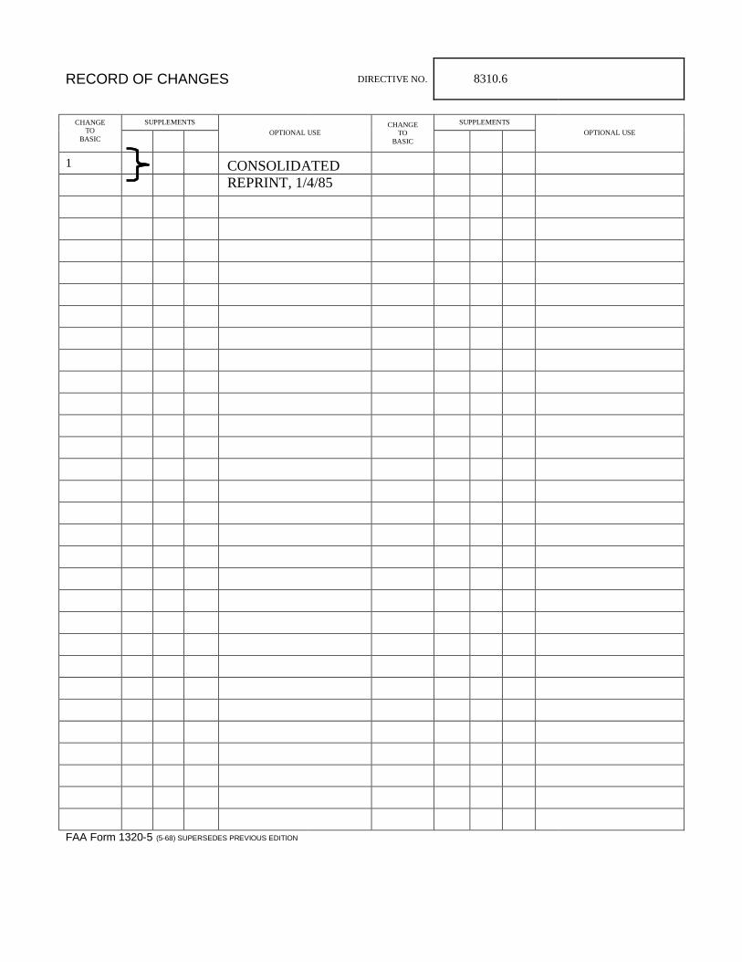
RECORD OF CHANGES DIRECTIVE NO. 8310.6
SUPPLEMENTS SUPPLEMENTS CHANGE
TO BASIC
OPTIONAL USE CHANGE
TO BASIC
OPTIONAL USE
1
FAA Form 1320-5 (5-68) SUPERSEDES PREVIOUS EDITION
CONSOLIDATED REPRINT, 1/4/85

8310.6 CHG 1 Page 1 10/27/71
FOREWORD
1. PURPOSE. This handbook provides guidance information to inspectors approving alteration data. The ACCS have been grouped into four broad chapter headings; however, the individual titles appropriate to the alteration and aircraft certification basis applicability have been retained.
2. CANCELLATION . Airworthiness Compliance Check Sheet Handbook FS P 8310.19 dated 8/20/62.
3. RELATIONSHIP TO FEDERAL AVIATION REGULATIONS . The data contained in this handbook reflects the requirements of FAR 23 and CAM 3 (whichever is applicable) in effect upon the date of issuance of the ACCS. It may be applied to aircraft type certificated prior to this date with the exception of CAR 4a-T, if the applicant so desires.
4. ISSUANCE AND USE . Information obtained from the use of the ACCS will provide a basis for the development of data for publication in AC 43.13-2.
5. INTRODUCTION : The applicable regulations shall be reviewed for changes which may affect the modification. Particular attention should also be placed on the possible effect of special regulations, policies and interpretations, or other data issued subsequent to these ACCSs.
There are four main headings under which compliance with the applicable regulations should be checked:
a. Structural requirements.
b. Hazards to the aircraft or its occupants.
c. Operating aspects.
d. Detail design standards.
*
*
*
*
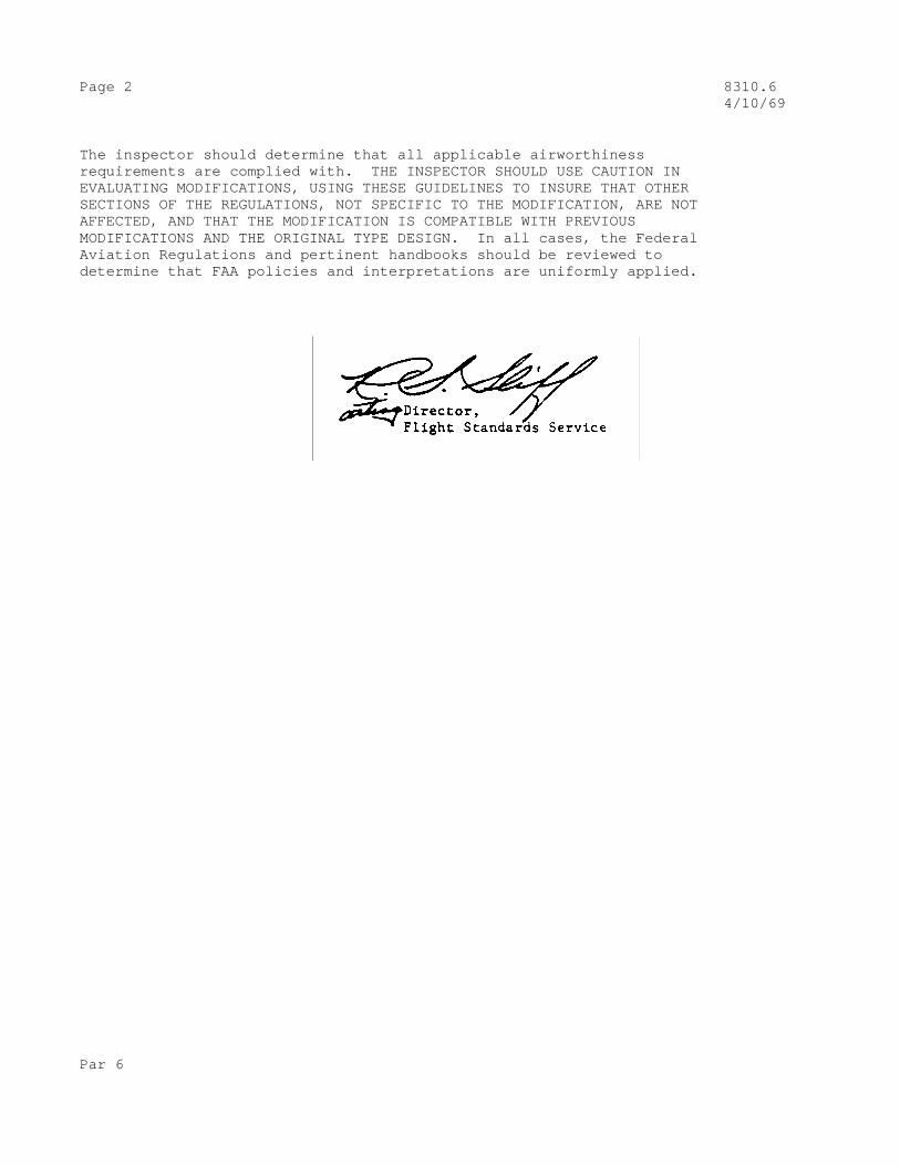
Page 2 8310.6 4/10/69
The inspector should determine that all applicable airworthiness requirements are complied with. THE INSPECTOR SHOULD USE CAUTION IN EVALUATING MODIFICATIONS, USING THESE GUIDELINES TO INSURE THAT OTHER SECTIONS OF THE REGULATIONS, NOT SPECIFIC TO THE MODIFICATION, ARE NOT AFFECTED, AND THAT THE MODIFICATION IS COMPATIBLE WITH PREVIOUS MODIFICATIONS AND THE ORIGINAL TYPE DESIGN. In all cases, the Federal Aviation Regulations and pertinent handbooks should be reviewed to determine that FAA policies and interpretations are uniformly applied.
Par 6

8310.6 CHG 1 Page i 4/10/69
TABLE OF CONTENTS
ACCS NO. PAGE
CHAPTER 1. POWERPLANT
1. Generator Installations – FAR 23 aircraft. 1
2. Generator Installations – FAR 25 aircraft. 5
3. Wind-Driven Generator Installations – FAR 23 aircraft 9
4. Motor and Dynamotor Installations – FAR 25 aircraft. 13
5. Engine lubricating Oil Filter Installation – FAR 23 aircraft. 17
6. Modification of an Airplane to Replace the Engine Exhaust System with One of New Design – FAR 23 aircraft. 19
7. Modification of an Electric Starting System by Sub- stitution of a starter made by a Different Manufacturer, Assuming that the Size and Shape of the Engine Mounting Pad is Correct – FAR 23 aircraft 23
8. Battery Installations – FAR 23 aircraft. 25
9. Battery Installations – FAR 25 aircraft. 29
10. Modification of an Airplane Involving Installation of a Fuel Flow Meter – FAR 23 aircraft. 33
11. Modification of a Fuel System by the Installation of a Fuel pump to Transfer Fuel from an Auxiliary to a Main Fuel Tank – FAR 23 Aircraft. 35
12. Modification of an Airplane to Relocate an Auxiliary Fuel Tank without Altering the Fuel System Arrangement - FAR 23 aircraft. 37
CHAPTER 2. AIRFRAME
13. Modification and/or Installation of Seats – FAR 23 aircraft. 41
14. Modification and/or Installation of Seats – FAR 25 aircraft. 45
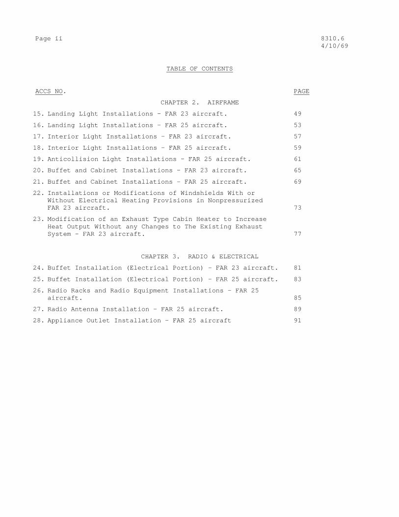
Page ii 8310.6 4/10/69
TABLE OF CONTENTS
ACCS NO. PAGE
CHAPTER 2. AIRFRAME
15. Landing Light Installations – FAR 23 aircraft. 49
16. Landing Light Installations – FAR 25 aircraft. 53
17. Interior Light Installations – FAR 23 aircraft. 57
18. Interior Light Installations – FAR 25 aircraft. 59
19. Anticollision Light Installations – FAR 25 aircraft. 61
20. Buffet and Cabinet Installations – FAR 23 aircraft. 65
21. Buffet and Cabinet Installations – FAR 25 aircraft. 69
22. Installations or Modifications of Windshields With or Without Electrical Heating Provisions in Nonpressurized FAR 23 aircraft. 73
23. Modification of an Exhaust Type Cabin Heater to Increase Heat Output Without any Changes to The Existing Exhaust System – FAR 23 aircraft. 77
CHAPTER 3. RADIO & ELECTRICAL
24. Buffet Installation (Electrical Portion) – FAR 23 aircraft. 81
25. Buffet Installation (Electrical Portion) – FAR 25 aircraft. 83
26. Radio Racks and Radio Equipment Installations – FAR 25 aircraft. 85
27. Radio Antenna Installation – FAR 25 aircraft. 89
28. Appliance Outlet Installation – FAR 25 aircraft 91

8310.6 Page iii 4/10/69
TABLE OF CONTENTS
ACCS NO. PAGE
CHAPTER 4. INSTRUMENTS
29. Instrument Installations – Relocating Instruments, FAR 23 aircraft. 93
30. Instrument Installations, Adding Instruments, FAR 23 aircraft. 97
31. Instrument Installations, Relocating Instruments, FAR 25 aircraft 99
32. Instrument Installations, Adding Instruments, FAR 25 aircraft. 103
33. Gyroscopic Instruments – FAR 23 aircraft. 105
34. Gyroscopic Instruments – FAR 25 aircraft. 107
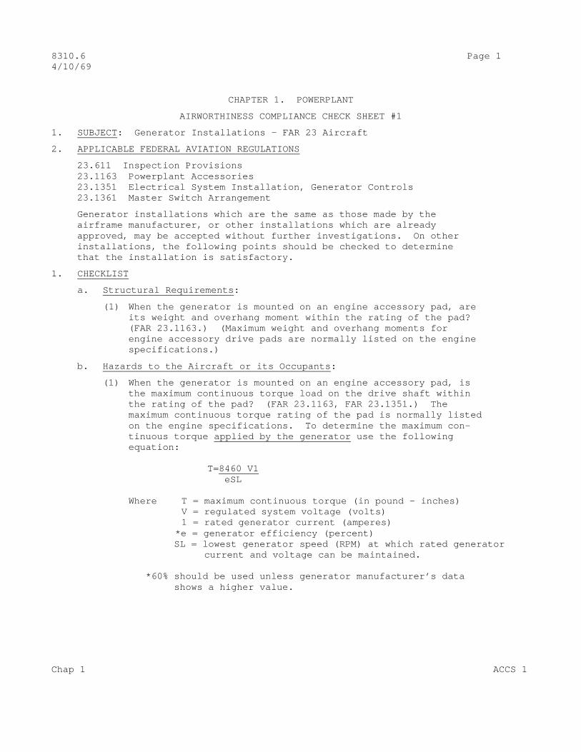
8310.6 Page 1 4/10/69
CHAPTER 1. POWERPLANT
AIRWORTHINESS COMPLIANCE CHECK SHEET #1
1. SUBJECT : Generator Installations – FAR 23 Aircraft
2. APPLICABLE FEDERAL AVIATION REGULATIONS
23.611 Inspection Provisions 23.1163 Powerplant Accessories 23.1351 Electrical System Installation, Generator Controls 23.1361 Master Switch Arrangement
Generator installations which are the same as those made by the airframe manufacturer, or other installations which are already approved, may be accepted without further investigations. On other installations, the following points should be checked to determine that the installation is satisfactory.
1. CHECKLIST
a. Structural Requirements :
(1) When the generator is mounted on an engine accessory pad, are its weight and overhang moment within the rating of the pad? (FAR 23.1163.) (Maximum weight and overhang moments for engine accessory drive pads are normally listed on the engine specifications.)
b. Hazards to the Aircraft or its Occupants :
(1) When the generator is mounted on an engine accessory pad, is the maximum continuous torque load on the drive shaft within the rating of the pad? (FAR 23.1163, FAR 23.1351.) The maximum continuous torque rating of the pad is normally listed on the engine specifications. To determine the maximum con- tinuous torque applied by the generator use the following equation: T=8460 V1 eSL Where T = maximum continuous torque (in pound – inches) V = regulated system voltage (volts) 1 = rated generator current (amperes) *e = generator efficiency (percent) SL = lowest generator speed (RPM) at which rated generator current and voltage can be maintained. *60% should be used unless generator manufacturer’s data shows a higher value.
Chap 1 ACCS 1

Page 2 8310.6 4/10/69
(2) When the generator is mounted on an engine accessory pad, is the shear section on the generator such that it will fail at a torque lower than the maximum static torque of the engine pad? (FAR 23.1163) (The maximum static torque for accessory pads is normally listed in the engine specifications.)
(3) Is the generator installed so as to minimize the possibility that arcing or sparks may come in contact with flammable fluids or vapors in a free state? (FAR 23.1163.)
NOTE: An evaluation should be made of the possibility of sparks or hot air from the generator cooling air outlets coming in contact with flammable fluids. An example would be locating the generator beneath an engine-driven fuel pump not properly fitted with overboard drain lines. A seal leak developing in the fuel pump could result in a fire.
(4) Is the electrical cable or wiring of the proper size for the electrical load involved and is it installed so as to mimimize the possibility of fire or smoke? (FAR 23.1351.)
NOTE: AC 43.13-1 Chapter 11.
(5) If electrical wiring or equipment is installed near the compass, was the compass checked for possible error? (FAR 23.1351.)
(6) Can maximum engine RPM be attained without danger of over- speeding the generator? (Refer to the generator nameplate, engine specifications and engine operating instructions for evaluation information.)
c. Operating Aspects :
(1) When the generator is required by the operating rules for operation under IFR, is its capacity sufficient to supply all probable combinations of continuous loads with adequate reserve for battery charging? Output ratings should be compared to maximum probable loads per AC 43.13-1, paragraph 238. (FAR 23.1351.) In no case shall the output exceed 80% of total rated generator capacity.
(2) Is the voltage regulator (associated with the generator) capable of maintaining rated voltage over the range of probable engine speeds at full electric system load? (FAR 23.1351.)
(3) Is the master switch provided which will disconnect the genera- tor from the main distribution system at a point adjacent to the generator? (FAR 23.1361.)
ACCS 1 Chap 1

8310.6 Page 3 (and 4) 4/10/69
d. Detail Design Standards :
(1) Is the generator installed so as to permit inspection of the condition of the brushes and wiring terminals without removal of adjacent equipment? (FAR 23.611.)
(2) Is the generator installed so as to be protected from fuel, oil, water, and other detrimental substances and mechanical damage? (FAR 23.1351.)
Chap 1 ACCS 1
8310.6 Page 5 4/10/69
AIRWORTHINESS COMPLIANCE CHECK SHEET #2
1. SUBJECT : Generator Installations – FAR 25 Aircraft
2. APPLICABLE FEDERAL AVIATION REGULATIONS
25.611 Inspection Provisions 25.1163 Powerplant Accessories 25.1309 Equipment, Systems, and Installations 25.1351 Electrical System Capacity
Generating System
25.1357 Electrical Protection
Generator installations which are the same as those made by the airframe manufacturer, or other installations which are already approved, may be accepted without further investigation. On other installations, the following points should be checked to determine that the instllation is satisfactory.
3. CHECKLIST
a. Structural Requirements :
(1) When the generator is mounted on an engine accessory pad is its overhang moment within the rating of the pad? (FAR 25.1163.) Maximum overhang moments for engine accessory drive pads are normally listed on the engine specifications.
b. Hazards to the Aircraft or its Occupants :
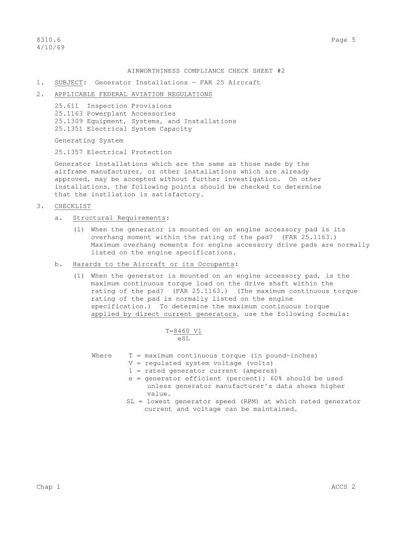
(1) When the generator is mounted on an engine accessory pad, is the maximum continuous torque load on the drive shaft within the rating of the pad? (FAR 25.1163.) (The maximum continuous torque rating of the pad is normally listed on the engine specification.) To determine the maximum continuous torque applied by direct current generators , use the following formula: T=8460 V1 eSL
Where T = maximum continuous torque (in pound–inches) V = regulated system voltage (volts) 1 = rated generator current (amperes) e = generator efficient (percent); 60% should be used unless generator manufacturer’s data shows higher value. SL = lowest generator speed (RPM) at which rated generator current and voltage can be maintained.
Chap 1 ACCS 2

Page 6 8310.6 4/10/69
(2) When the generator is mounted on an engine accessory pad, is the shear section on the generator such that it will fail at a torque lower than the maximum static torque of the engine pad? (FAR 25.1163.) (The maximum static torque for accessory pads is normally listed in the engine specifications.)
(3) Does the rated continuous rotational speed of the generator correspond approximately with drive shaft RPM when the engine is operated at cruise RPM? (FAR 25.1163.)
(4) Is the generator installed so as to minimize the possibility that arcing or sparks may come in contact with flammable fluids or vapors in a free state? (FAR 25.1163.)
(5) Is the generating system (including regulators and controls) so designed that no probable malfunction can result in permanent loss of electrical service to utilization systems which are necessary to maintain controlled flight or effect a safe landing? (FAR 25.1351.)
(6) Is the generating system provided with a device which will disconnect a generator which produces hazardous over-voltage? (FAR 25.1357.) (By hazardous overvoltage is meant an overvoltage of such magnitude and duration as could render essential electrical equipment inoperative.)
c. Operating Aspects :
(1) Are the generators so rated and distributed among the engines that the electric power system is capable of supplying (in probable operating combinations and for probable durations) (a) all loads connected to the system with the system functioning normally? (b) all essential loads after failure of any one engine, generator or storage battery? (c) all essential loads after failure of any two engines on four-or-more-engine airplanes? (FARs 25.1309, and 25.1351.)
NOTE: A load is defined as essential when its functioning is necessary in showing compliance with the regulations (FAR 25.1309.) Load reduction is permissible if the generators can safely handle any temporary overload condition and if the crew is warned that partial electric power system failure has occurred (FAR 25.1351). If a particular load is not required to maintain controlled flight, it need not be considered as an essential load in condition (c) above. (FAR 25.1309.)
(2) Are accessible controls provided to permit independent disconnec- tion of each generator form the electric power system during flight? (FAR 25.1351.)
ACCS 2 Chap 1

8310.6 page 7 (and 8) 4/10/69
(3) Are the generator controls (provided in (b) above) so grouped so as to permit expeditious disconnection of all generators? (FAR 25.1351.)
(4) Are means provided to indicate to appropriate crew members those generating system quantities which are essential for safe operation of the system? (For direct current systems, the voltage and current supplied by each generator are considered essential.) (FAR 25.1351.)
d. Detail Design Standard :
(1) Is the generator capable of withstanding the probable extremes in environmental conditions to which it will be subjected? (FAR 25.1353.)
Environmental conditions which should be considered would include vibration, temperature, altitude, and cooling.
(2) Is the generator installed so as to permit inspection of the condition of the brushes and wiring terminals without removal of adjacent equipment? (FAR 25.611.)
Chap 1 ACCS 2
8310.6 Page 9 4/10/69
AIRWORTHINESS COMPLIANCE CHECK SHEET #3
1. SUBJECT : Wind-Driven generator Installations FAR 23 Aircraft
2. APPLICABLE FEDERAL AVIATION REGULATIONS
23.611 Inspection Provisions 23.1351 Electrical System Installation 23.1361 Master Switch Arrangement 23.301 Strength Requirements, General .303 .305 .307 23.321 Flight Loads 23.471 Ground Loads 23.601 Design and Construction, General .603 .605 .607 .609 .611 23.629 Flutter and Vibration Prevention 91.167 Test Flight Passenger Provisions
3. CHECKLIST
a. Structural Requirements
(1) Is the installation satisfactory for the required loads? (FAR 23.301, .303, .305, .307, .321, .471)
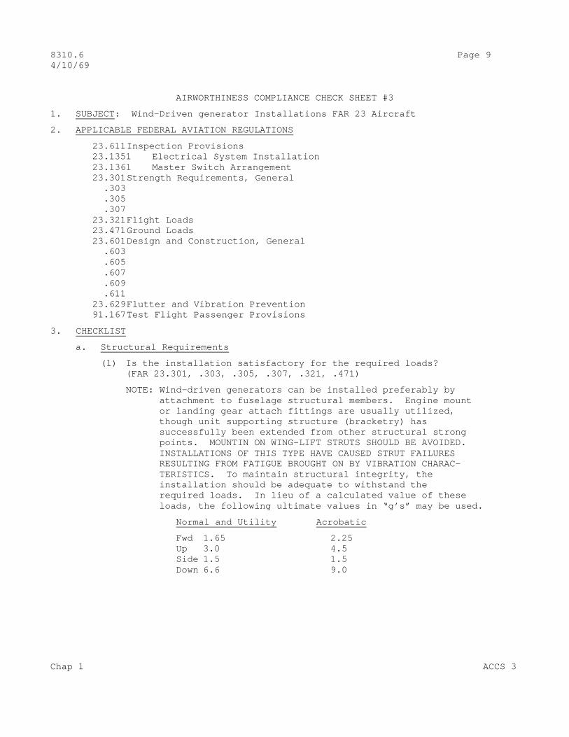
NOTE: Wind-driven generators can be installed preferably by attachment to fuselage structural members. Engine mount or landing gear attach fittings are usually utilized, though unit supporting structure (bracketry) has successfully been extended from other structural strong points. MOUNTIN ON WING-LIFT STRUTS SHOULD BE AVOIDED. INSTALLATIONS OF THIS TYPE HAVE CAUSED STRUT FAILURES RESULTING FROM FATIGUE BROUGHT ON BY VIBRATION CHARAC- TERISTICS. To maintain structural integrity, the installation should be adequate to withstand the required loads. In lieu of a calculated value of these loads, the following ultimate values in “g’s” may be used.
Normal and Utility Acrobatic
Fwd 1.65 2.25 Up 3.0 4.5 Side 1.5 1.5 Down 6.6 9.0
Chap 1 ACCS 3
Page 10 8310.6 4/10/69
With a relatively lightweight generator installation a reasonably accurate check of these values can usually be made by grasping the installation by hand and pulling or pushing in the required direction.
(2) Are the flutter or vibration characteristics of the installation satisfactory? (FAR 23.629)
Note: The relatively light weight of these installations should not normally affect the flutter and vibration properties of the airplane as a whole. There is a possibility, however, of unit vibration being transmitted to the airplane. This should be checked both on the ground during taxiing and in flight up to V NE. If a generator brake is installed, the tests should be accomplished with the propeller fixed as well as windmilling. V NE should be approached with caution during these tests. (FAR 91.167)
b. Hazards to the Aircraft and Its Occupants
(1) Is the electrical cable or wiring of the proper size for the electrical load involved and is it installed so as to minimize the possibility of fire or smoke? (FAR 23.1351, AC 43.13-1)
(2) If electrical wiring or equipment is installed near the compass, was the compass checked for possible error? (FAR 23.1351)
(3) If the generator is so located that the extended propeller disc will intersect any portion of the pilot or passenger, are such persons adequately protected from injury due to a flying generator propeller blade? (FAR 23.1351)
(A sheet of .032 heat treated aluminum alloy or .25 inch plywood is considered sufficient to furnish adequate protection.)
c. Operating Aspects
(1) When the generator is required by the operating rules (for operation under Instrument Flight Rule), is its capacity sufficient to supply all probable combinations of continuous loads with adequate reserve for battery charging? Output ratings should be compared to maximum probable loads per AC 43.13-1, paragraph 238. (FAR 23.1351, FAR 23.1351)
(2) Is the generator propeller correct for developing the required output in relation to aircraft airspeed? (FAR 23.1351)
ACCS 3 Chap 1

8310.6 Page 11 (and 12) 4/10/69
(3) Is the voltage regulator (associated with the generator) capable of maintaining voltage within rated limits at cruise airspeeds with full electric system load applied?
(4) Are there automatic means provided to prevent current from flowing from the battery into the generator when the generator voltage becomes lower than the battery voltage? (FAR 23.1351)
(This function is normally provided by the regulator or generator contol unit.)
(5) Is a master switch provided which will disconnect the generator from the main distribution system at a point adjacent to the generator? (FAR 23.1361)
d. Detail Design Standard
(1) Is the generator installed so as to permit inspection of the condition of the brushes and wiring terminals without removal of adjacent equipment? (FAR 23.611)
(2) Is the generator installed so as to be protected from fuel, oil, water, and other detrimental substances and mechanical damage? (FAR 23.1357)
(3) Is the material used in the installation satisfactory for the purpose intended and of an approved type, and is the workmanship of a high standard? (FAR 23.603)
(Approved materials are those produced to a government specification or established industry standard.)
(4) Will the method of fabrication used result in a consistently sound structure and are standard fasteners (approved type; i.e., AN, NAS, SAW, MIL, etc.) used? (FAR 23.605, 23.607)
(5) Are all members suitably protected against weathering, corrosion, and abrasion? Particular care should be taken with seaplanes where parts of different metals are in close proximity. (FAR 23.609)
Chap 1 ACCS 3
8310.6 Page 13 4/10/69
AIRWORTHINESS COMPLIANCE CHECK SHEET #4
1. SUBJECT . Motor and Dynamotor Installations – FAR 25 Aircraft.
2. APPLICABLE FEDERAL AVIATION REGULATIONS .
21.305 Approval of Materials, Parts, Processes and Appliances 25.301 Loads 25.303 Loads 25.305 Strength and Deformation 25.307 Proof of Structure 25.321 Flight Loads 25.365 Flight Loads 25.367 Flight Loads 25.471 Ground Loads 25.473 Ground Loads 25.489 Ground Loads 25.491 Ground Loads 25.499 Ground Loads 25.503 Ground Loads 25.507 Ground Loads 25.511 Ground Loads 25.561 Emergency Landing Conditions 25.603 Materials 25.605 Fabrication Methods 25.607 Standard Fastenings 25.609 Protection 25.611 Inspection Provisions 25.615 Material Strength Properties and Design Values 25.863 Flammable Fluid Fire Protection 25.1309 Equipment, Systems, and Installations 25.1357 Electrical Protection 25.1353 Electrical Equipment and Installations 25.1359 Electrical System Fire and Smoke Protection
Motor or dynamotor installations which are the same as those made by the airframe manufacturer, or other installations which are a already approved, may be accepted without further investigation. On other installations the following points should be checked to determine that the installation is satisfactory.
3. CHECKLIST .
a. Structural Requirements .
(1) Is the equipment installed in such a manner that the installation can withstand the required loads? The effect on other structure (primary or secondary) should be considered. (FARs 25.301, 25.303, 25.305, 25.307, 25.321, 25.365, 25.367, 25.373, 25.471, 25.473, 25.489, 25.491, 25.499, 25.503, 25.507, 25.511).
Chap 1 ACCS 4
Page 14 8310.6 4/10/69
NOTE: This answer can be determined by a direct comparison with an existing approved installation having the same or similar (approximately same weight and size) equipment installed, by structural analysis, or by static test.
Such installations do not necessarily lend themselves to analysis but are adaptable to static test. In conducting this test, the following procedure may be used:
(a) Determine the weight and c.g. of the equipment.
(b) Mount the equipment in the position in the airplane or simulate the equipment with a dummy so that the required loads can be applied at the c.g. position of the actual equipment.
(c) The required loads should then be applied by any suitable means. If the equipment is light in weight, the inspector could use his own strength and/or weight to determine that the installation will withstand the required loads.
All items of mass which would be apt to injure the passengers or crew in the event of a crash landing should have their supporting structure designed to the crash load requirements or the applicable critical flight or landing load factors of FAR 25.301, 25.303 or 25.471, 25.473, 25.489, 25.491, 25.499, 25.503, 25.507, 25.511, whichever is greater.
Supporting structure of other mass items should be designated to the critical flight or landing load factors of FAR 25.301, 25.303 or 25.471, 25.473, 25.489, 25.491, 25.499, 25.503, 25.507, 25.511. The values shown in FAR 25.561 may be used in lieu of a determination of these values.
(2) Are suitable materials used in the construction, including standard fasteners, and will the method of fabrication result in a consistently sound structure? (FARs 25.603, 25.605, 25.607, 25.615, 21.305)
(3) Are means provided to permit proper inspections of the installation and related or adjacent parts and components? (FAR 25.611)
b. Hazards to the Aircraft and its Occupants
(1) Is a fuse or circuit breaker of the appropriate rating installed in the connecting cables? (FAR 25.1357)
ACCS 4 Chap 1
8310.6 Page 15 (and 16) 4/10/69
(2) If a circuit breaker is installed, is it of a type which will open the circuit irrespective of the position of the control in case of a fault? (FAR 25.1357)
(3) If the motor or dynamotor performs a function essential to safety, is its circuit protective device (fuse or circuit breaker) located so that it is accessible for replacement or resetting in flight? (FAR 25.1357)
(4) Are any connecting cables, which are necessary in emergency procedures and located in designated fire zones, fire- resistant? (FAR 25.1359)
An accepted criterion for “fire-resistant” is that the cable should withstand a 2000 °F. oxidizing flame impinging on its surface for at least 5 minutes without adverse effect on the circuit function. The 2000 °F. oxidizing flame should envelop at least a 12 inch section of the cable, using a test setup simulating the actual aircraft installation. Thermocouples for measurement of flame temperature should be located within one-fourth inch of the surface exposed to the flame.
(5) If the motor or dynamotor is located in areas of the airplane where flammable fluids or vapors might be liberated by leakage or failure in fluid systems, are design precautions made to either prevent ignition of such fluids (due to operation of the motor or dynamotor) or to control any fire resulting from such ignition? (FARs 25.863 and 25.1359)
(6) If a probable malfunction in motor or dynamotor can generate hazardous quantities of smoke within the cabin, are adequate means provided to detect the faulty machine and to disconnect it from the source of power? (FAR 25.1359)
c. Operational Aspects ;
None
d. Detail Design Standards :
(1) If the motor or dynamotor performs a function which is essential to safety, will this function be performed reliably under all reasonably foreseeable environmental conditions? (FARs 25.1309 and 25.1353)
NOTE: Environmental conditions may include extremes of temperature, pressure, humidity, ventilation, position, acceleration, vibration and presence of detrimental substances.
(2) Are adequate means provided to examine the equipment to determine brush condition and for lubrication, if required? (FAR 25.611)
Chap 1 ACCS 4

8310.6 Page 17 4/10/69
AIRWORTHINESS COMPLIANCE CHECK SHEET #5
1. SUBJECT : Engine Lubrication Oil Filter Installation – FAR 23 Aircraft
2. APPLICABLE FEDERAL AVIATION REGULATIONS :
23.301 Loads 23.1017 Oil system lines, fittings, and accessories 23.1019 Oil filters 23.1021 Oil system drains 23.1121 Exhaust system, general 23.1183 Lines and fittings 23.1337 Instrument lines
Engine lubricating oil filters designed to remove solid particles and other contaminants from the oil during circulation are of two general types: (a) full flow filters in which the entire flow of oil passes through the filter, and (b) bypass filters in which a small portion of the total oil flow is diverted through the filter and returned to the engine sump or oil tank.
The installation of an oil filter shall not be a substitute for the engine screen, strainer, or cleaner provided by the engine manufacturer, unless the installation has been evaluated by the engine manufacturer and found to provide equivalent or better protection. Oil filter installations approved on an STC have been coordinated with the engine manufacturer and are acceptable in lieu of the engine screen. Filter installations which are the same as those made by the engine or aircraft manufacturer, or other installations which are already approved for a particular model of aircraft or engine, may be accepted without further investigation. On other installations, the following points should be checked to determine that the installation is satisfactory.
3. CHECKLIST
a. Structural Requirements
(1) If the filter housing is mounted on existing structure or on a bracket attached to such structure, is all of the structure adequate to support the required loads? (FAR 23.301.)
b. Hazards to the Aircraft and its Occupants
(1) Is the pressure line to the filter 1/ provided with a restricted orifice at the point of pressure takeoff at the engine, to minimize escape of oil in case of connecting line failure? (FAR 23.1337) 1/ This applies to a bypass filter only, since a restricted orifice
would prevent the proper oil flow rate through a full flow filter.
Chap 1 ACCS 5
Page 18 8310.6 4/10/69
(2) Are the filter and connection lines installed away from or under the exhaust system to minimize the possibility of oil leakage contacting the exhaust manifold? (FAR 23.1121)
c. Operating Aspects :
(1) Does an investigation, at all power ratings, of the engine oil pressure prior to and subsequent to the filter installation indi- cate that there is no difference in engine oil pressure? (FAR 23.1019)
d. Detail Design Standards
(1) If the filter is mounted in the engine compartment, are the lines and fittings (which are under pressure, or which attach directly to the engine, or which are subject to relative motion between components) flexible, fire-resistant lines with fire-resistant end fittings of the permanently attached, detachable or other approved type? (FARs 23.1017 and 23.1183)
(2) Is the filter * constructed so that complete stoppage of flow through the filter element will not jeopardize the continued operation of the engine oil supply system? (FAR 23.1019)
* Not a critical item for a bypass filter, since the oil circulation system will continue to function even if the filter is completely clogged. A full flow filter must be equipped with a flow relief valve that opens when a preset differential pressure across the filter element is exceeded. This condition will exist for starting when the oil is cold and, also, when the service life of the filter element is reached and no additional solids can be retained by the filter element.
(3) Has the filter been substantiated for the pressure to which it will be subjected when installed? (FAR 23.1019)
(4) If the filter housing is equipped with a drain, does the drain plug or valve incorporate means for positive locking or safetying? (FAR 23.1021)
(5) If the filter housing is equipped with a removable cover, does the cover wing nut or bolt incorporate means for locking after tightening? (AC 43.13-1, Chap. 5-127)
ACCS 5 Chap 1
8310.6 Page 19 4/10/69
AIRWORTHINESS COMPLIANCE CHECK SHEET #6
1. SUBJECT : Modification of an Airplane to Replace the Engine Exhaust System With One of New Design – FAR 23 Aircraft.
2. APPLICABLE FEDERAL AVIATION REGULATIONS
23.1121 Exhaust System – General 23.1121 Exhaust Manifold
The primary function of the exhaust manifold is to conduct exhaust gases overboard with minimum hazard to the airplane and pilot. The system must be reliable, exert a minimum back pressure, be accessible for inspection and not interfere with engine-cooling airflow. The material must be particularly suitable for operation under high temperature and corrosive effects of the gas,and the weight should be held to a minimum consistent with the needs of the system.
3. CHECKLIST
a. Structural Requirements :
(1) For any change or alteration of the airplane structure, have the original strength and integrity of the structure been retained? (AC 43.13-2 Chapter 1)
Note : If the specific alteration cannot be evaluated using AC 43.13 or equivalent reference, it should be referred to the Engineering Service Representative.
(2) Is the exhaust manifold properly supported and attached to the engine so that vibration and any other loads imposed during normal operation will not affect the service life of the manifold? (FAR 23.1123.)
NOTE: Brackets supporting the manifold should be properly attached to the engine. Attachment to any highly stressed components, such as cylinder hold-down studs, crankcase studs, and through bolts should be avoided.
b. Hazards to the Aircraft or its Occupants :
(1) Are any of the exhaust system components located near any systems carrying flammable fluids or vapors? (FAR 23.1121.)
(2) Whose exhaust system components are unavoidably located near systems carrying flammable fluids or vapors, have suitable precautions been taken to preclude a fire hazard? (FAR 23.1121.)
Chap 1 ACCS 6

Page 20 8310.6 4/10/69
(3) Are any drain lines or fittings which may be subject to leakage located over exhaust manifolds, thus creating a fire hazard? (FAR 23.1121.)
(4) Have fireproof shields been provided between the exhaust mani- fold and any flammable parts of the airplane structure? (FAR 23.1121.)
(5) Is the exhaust tailpipe so located so that glare could affect the pilot’s visibility, particularly during night flight? (FAR 23.1121.)
(6) Is it possible for exhaust gas to enter any par of the airplane, particularly personnel compartments? (FAR 23.1121.)
Note: If the answer to item (6) is “yes” or questionable, the Engineering Service Representative should be contacted to conduct tests to determine if carbon monoxide contamination of cabin air is occurring. Carbon monoxide content should not exceed one part in 20,000.
c. Test Procedure to Determine CO Content :
(1) A carbon monoxide indicator should be used in determining compliance with the above requirement. The instrument manufactured by the Mines Safety Appliance Company or the Bulb Type Colorimetric Indicator may be used for this purpose, one of which is located at each Flight Engineering and Factory Inspection Branch Office. The following procedure should be used:
(a) The aircraft should be flown in level flight at MC power or as nearly so as possible. Carburetor should be set full rich with all window closed; readings should be taken in at least the following locations:
1 Along the floor (approximately 4 inches above) in front of each occupant.
2 On each side of the cabin approximately a foot forward of each occupant.
3 A few inches in front of each occupant’s face.
4 In front of the cabin heater opening(s) with heat on.
(b) Conduct the same investigation as outlined in (a) 1 through 3 except with windows partially open, thus tending to produce a vacuum in the cabin.
ACCS 6 Chap 1

8310.6 Page 21 (and 22) 4/10/69
(c) The aircraft should then be flown in a glide with power off (idling) and readings taken a few inches in front of each occupant’s face with both windows open and closed as in paragraph (b)?
(d) The highest reading obtained at any of the above points shall not exceed .005%.
d. Operating Aspects :
(1) Does the new exhaust manifold appear to be substantially the same in design dimensions and attachment as the old one?
NOTE: Check the following in making this comparison:
(a) Has the arrangement been changed?
(b) Has the diameter (cross sectional area) of any of the pipe sections been decreased?
(c) Has the length of any of the pipe sections been changed?
If the comparison reveals a substantial change, refer to the Engineering Service Representative for a back pressure test.
d. Detail Design Standards
(1) Is the manifold constructed of suitable fireproof, corrosion- resistant material? (FAR 23.1123.)
(2) Will expansion due to operating temperatures result in failure of the components? (FAR 23.1121.)
(3) Where necessary, are provisions incorporated for flexibility? (FAR 23.1123)
Chap 1 ACCS 6
8310.6 Page 23 4/10/69
AIRWORTHINESS COMPLIANCE CHECK SHEET #7
1. SUBJECT : Modification of an Electric Starting System by Substitution of a Starter made by a Different Manufacturer, Assuming that the Size and Shape of the Engine Mounting Pad is Correct – FAR 23 Aircraft
2. APPLICABLE FEDERAL AVIATION REGULATIONS .
23.901 Components 23.1163 Powerplant Accessories 23.1351 Installation 23.1357 Fuses or Circuit Breakers
Consideration must be given to the fact that prescribed engine or starter mechanical limitations cannot be exceeded. Electrical limitations and devices such as relays, switches and the current carrying capacity of wires must also be evaluated.
3. CHECKLIST
a. Structural Requirements :
(1) Is the starter constructed, arranged and installed to assure continued safe operation of the airplane and powerplant? (FAR 23.901)
(2) Is the allowable weight and overhang moment of the starter less than that recorded in the engine specification for the applicable mounting pad? (FAR 23.1163)
NOTE: The overhang moment is the product of the weight (pounds) of the starter and the distance (inches) from the mounting end to the center of gravity of the starter.
b. Hazards :
(1) Does the starter incorporate electrical protective devices such as fuses or circuit breakers? (FAR 23.1357)
NOTE: Fuses are not required in the main circuits of the starter motor; therefore, either answer is acceptable. This question has been incorporated to make this information a matter of record.
(2) Are the switches, relays, engaging solenoids and wire size proper for the starter and the electrical service provided by the battery or ground power source? (FAR 23.1351)
Chap 1 ACCS 7

Page 24 8310.6 4/10/69
(3) Is the starter motor installed so as to minimize contact with inflammables from fluid or vapor lines in the event of arcing or sparking of the motor?
c. Operational :
(1) Does the starter dog properly mesh and fully engage the engine dog, when the meshing cable or solenoid is actuated? (FAR 23.1163)
(2) Is there adequate clearance between the starter and engine dogs in the fully retracted position, to prevent riding of the dogs? (Refer to manufacturer’s instruction manual for clearance.) (FAR 23.1163)
d. Detail Design :
(1) Is the starter of a type that is acceptable under one of the following means?
(a) Qualification under an AN or MIL specification. (b) Completing a qualification test approved by FAA. (c) Prior satisfactory service, record on another approved installation.
(FAR 23.1163)
(2) Will the starter dog turn in the direction of rotation required by the engine dog? (FAR 23.1163)
(3) Is the speed ratio of the starter accessory drive correct as recorded in the engine specification? (FAR 23.1163)
(4) Is the maximum static torque delivered by the starter less than that specified in the engine specification? (FAR 23.1163)
(5) Is the starter overload prevention mechanism satisfactory to permit engaging and disengaging in order to deliver sufficient but not excessive cranking torque to motor the engine? (FAR 23.1163)
(6) Is the starter clearance envelope satisfactory with respect to interference, accessibility, inspection, maintenance, removal, and electrical connections to be made? (FAR 23.901)
(7) Is the starter motor suitably protected from fuel, oil, water, and other detrimental conditions? (FAR 23.1351)
ACCS 7 Chap 1

8310.6 Page 25 4/10/69
AIRWORTHINESS COMPLIANCE CHECK SHEET #8
1. SUBJECT : Battery Installations – FAR 23 Aircraft
2. APPLICABLE FEDERAL AVIATION REGULATIONS
23.301 Loads 23.307 Proof of Structure 23.337 Maneuvering Load Factors 23.341 Gust Load Factors 23.473 Load Factor for Landing Conditions 23.605 Fabrication Methods 23.613 Material Strength Properties and Design Values 23.561 Protection 23.1351 Batteries 23.1353 Storage Battery Design and Installation
Battery installations which are the same as those made by the airframe manufacturer, or other installations which are already approved, may be accepted without further investigation. On other installations the following points should be checked to determine that the installation is satisfactory.
3. CHECKLIST
a. Structural Requirements :
(1) Is the battery installed in such a manner that it can withstand the required loads? (FARs 23.301, 23.337, 23.341, and 23.473.) (See paragraph (3)(b) below.)
(2) If a mounting bracket is used, will the method used in its fabrication produce a consistently sound structure? (FAR 23.605.)
(3) If the equipment is mounted either on existing structure or on a bracket attached to existing structure, is all of the structure (including the bracket, if used) adequate to support the required loads? (FAR 23.307, 23.613, and 23.561.) This answer can be determined by either of two methods:
(a) By direct comparison with an existing approved installation having the same or similar (approximately the same weight and size) equipment installed.
(b) By structural analysis or static test. Such installa- tions do not lend themselves readily to analysis, but are normally adaptable to static test. In conducting a static test, the following procedure may be used:
Chap 1 ACCS 8

Page 26 8310.6 4/10/69
1 Determine the weight and c.g. position of the equipment item.
2 Mount the equipment in its position in the airplane or simulate the equipment with a dummy so that the required loads can be applied at the c.g. position of the actual equipment.
3 The required loads should then be applied by any suitable means. If the equipment is light in weight, the inspector could use his own strength and/or weight to determine that the mounted equipment meets the required loads.
In accordance with FAR 23.561, all items of mass which would be apt to injure the passengers or crew in the event of a minor crash landing should have their supporting structure designed to the crash load require- ments of FAR 23.561 insofar as the forward, upward, and sideward directions are concerned. The applicable downward load factor shall be the critical flight or landing load factor specified in FAR 23.341 and 23.473. In lieu of a calculated determination of the down load factor, the ultimate factors of 6.6, 6.6, and 9.0 may be used for the normal, utility, and acrobatic cate- gories, respectively. For equipment location not covered by FAR 23.561, the required loads (ref. FAR 23. 301) are the flight and landing load factors of FARs 23.337, 23.341, and 23.473. In lieu of a calcu- lated determination of these loads, the down load factors referenced above may be used.
(4) Is the equipment so installed that is does not adversely affect other structure (either primary or secondary)? (FAR 23.1431.)
b. Hazards to the Aircraft and its Occupants :
(1) Are the parts of the airplane adjacent to the battery protected against corrosion from any products likely to be emitted by the battery during servicing or flight? (FAR 23.1353.)
(Methods which may be used to obtain protection include: acid- proof paint which will resist corrosive action by emitted electrolyte, drain to discharge corrosive liquids clear of the aircraft, positive pressure vents to carry corrosive fumes.
ACCS 8 Chap 1
8310.6 Page 27 (and 28) 4/10/69
outside the aircraft, enclosed battery cases which would contain any amount of electrolyte that might be spilled, or combinations of these methods.)
(2) Is the battery container or compartment vented in such a manner that any explosive gases released by the battery during flight are carried outside the airplane?
(3) Is the battery container or compartment vented in such a manner that any noxious gases emitted by the battery are directed away from the crew and passengers?
(4) Are the battery connector terminals or other exposed parts protected against electrical contact with the battery container or compartment? (FAR 23.1351.)
c. Operating Aspects :
(1) If a battery is the only source of electrical power, does the battery have sufficient capacity to supply the electrical power necessary for dependable operation of all electrical equipment essential to the safe operation of the airplane? (FAR 23.1351.)
(The necessary capacity can be determined by assuming the loads (including nonessential loads) connected in probable combination and for probable durations under those flight conditions which would require the greatest amount of electrical energy. The current drained from the battery will have different values during the flight. Obtain the average current and multiply by the maximum flight duration in hours. This the ampere-hour capacity required for the battery at a discharge time rate equal to the maximum flight duration time of the airplane.)
d. Detail Design Standards :
(1) Is the battery accessible for inspection or servicing on the ground? (FAR 23.1353.)
Chap 1 ACCS 8

8310.6 Page 29 4/10/69
AIRWORTHINESS COMPLIANCE CHECK SHEET #9
1. SUBJECT : Battery Installations – FAR 25 Aircraft
2. APPLICABLE FEDERAL AVIATION REGULATIONS
25.301 Loads 25.305 Strength and Deformation 25.307 Proof of Structure 25.321 Flight Loads 25.471 Ground Loads 25.561 Emergency Landing Conditions 25.603 Materials 25.605 Fabrication Methods 25.607 Standard Fastenings 25.609 Protection 25.611 Inspection Provisions 25.613 Material Strength Properties and Design Values 25.1353 Electrical Equipment and Installations
Battery installations which are the same as those made by the airframe manufacturer, or other installations which are already approved, may be accepted without further investigation. On other installations, the following points should be checked to determine that the installation is satisfactory.
3. CHECKLIST
a. Structural Requirements :
(1) Is the battery installed in such a manner that the installation can withstand the required loads? The effect on other structure (primary or secondary) should be considered. (FARs 25.301, 25.305, 25.307, 25.321, 25.471, and 25.561.)
NOTE: This answer can be determined by a direct comparison with an existing approved installation having the same or similar (approximately same weight and size) equipment installed, by structural analysis, or by static test. Such installations do not necessarily lend themselves to analysis but are adaptable to static test. In conducting this test, the following procedure may be used:
(a) Determine the weight and c.g. of the equipment.
(b) Mount the equipment in the position in the airplane or simulate the equipment with a dummy so that the required loads can be applied at the c.g. position of the actual equipment.
Chap 1 ACCS 9

Page 30 8310.6 4/10/69
(c) The required loads should then be applied by any suitable means. If the equipment is light in weight, the inspector could use his own strength and/or weight to determine that the installation will withstand the required loads.
NOTE: All items of mass which would be apt to injure the passengers or crew in the event of a crash landing should have their supporting structure designed to the crash load requirements of FAR 25.561 or the applicable critical flight or landing load factors of FARs 25.321, or 25.471, whichever is greater.
Supporting structure of other mass items should be designed to the critical flight or landing load factors of FARs 25.321, or 25.471. The values shown in FAR 25.561 may be used in lieu of determination of these values.
(2) Are suitable materials used in the construction, including standard fasteners, and will the method of fabrication result in a consistently sound structure? (FARs 25.603, 25.605, 25.607, 25.613, and 21.305.)
(3) Are means provided to permit proper inspections of the installation and related adjacent parts as components? (FAR 25.611.)
b. Hazards to the Aricraft and its Occupants:
(1) Is the battery container or compartment vented in such a manner that any gases or fumes emitted by the battery are carried outside the airplane? (FAR 25.1353.)
(2) Are the parts of the airplane adjacent to the battery protected against corrosion from any products likely to be emitted by the battery during servicing or flight? (FARs 25.1353, and 25.609.)
(Methods which may be used to obtain protection include: acid proof paint which will resist corrosion by emitted electrolyte, drains to discharge corrosive liquids clear of the aircraft, positive pressure vents to carry corrosive fumes outside the aircraft, enclosed battery cases which would contain any amount of electrolyte that might be spilled, or combinations of these methods.)
(3) Is adequate provision made for the drainage of spilled or excess battery fluid? (FAR 25.1353.)
ACCS 9 Chap 1

8310.6 Page 31 (and 32) 4/10/69
c. Operating Aspects :
None
d. Detail Design Standards :
None
Chap 1 ACCS 9

8310.6 Page 33 4/10/69
AIRWORTHINESS COMPLIANCE CHECK SHEET #10
1. SUBJECT : Modification of an Airplane Involving Installation of a Fuel Flowmeter – FAR 23 Aircraft
2. APPLICABLE FEDERAL AVIATION REGULATIONS
23.955 Fuel Flow Rate Fuel Flow Rate for Gravity Systems Fuel Flow Rate for Pump Systems Fuel Flow Rate for Auxiliary Fuel Systems and Fuel Transfer Systems 23.993 Fuel System Lines and Fittings 23.1183 Lines and Fittings 23.1337 Fuel Flowmeter System TSO-C44 Fuel Flowmeters
Whenever a flowmeter is installed in the fuel system, the fuel flow rate will be affected. To determine if an adequate supply of fuel is available at the carburetor, it is necessary to conduct fuel flow tests. The tests may be conducted on the airplane or on a suitable mockup which duplicates the particular fuel system. The Engineering Service Representative should be contacted with reference to conducting the necessary tests.
3. CHECKLIST
a. Structural Requirements :
(1) If changes or alterations of the airplane structure are made, has the original strength and integrity of the structure been retained? (AC 43.13-2 Chapter 1.)
NOTE: If the specific alteration cannot be evaluated using AC 43.13-1 or equivalent references, it should be referred to the Engineering Service Representative.
(2) If additional lines are required for the installation, are they properly installed and supported? (FAR 23.993.)
b. Hazards to the Aircraft or its Occupants :
(1) All lines and fittings installed in connection with the flowmeter will be under pressure. Does the installation comply with the powerplant fire protection provisions? (FAR 23.1183.)
Chap 1 ACCS 10

Page 34 8310.6 4/10/69
c. Operating Aspects :
(1) Do test results show an adequate supply of fuel at the carbure- tor during normal operation and with the metering element blocked? (FAR 23.995.)
d. Detail Design Standards :
(1) To insure an airworthy installation, is the flowmeter of an approved type?
Flowmeters approved for installation in civil aircraft prior to October 15, 1967, may continue to be used. New models of fuel flowmeters manufactured after October 15, 1967, shall con- form to the requirements of TSO-C44. In either case, final approval is dependent of the satisfactory installation of the flowmeter in the airplane.
(2) Is the indicator and associated components properly installed?
To insure that the indicator and its associated components have been properly installed, the manufacturer’s installation instructions should be reviewed. The Engineering Service Representative should be contacted for assistance in making this determination unless a supplementary compliance check sheet is available which covers the instrument installation portion.
ACCS 10 Chap 1
8310.6 Page 35 4/10/69
AIRWORTHINESS COMPLIANCE CHECK SHEET #11
1. SUBJECT : Modification of a Fuel System by the Installation of a Fuel Pump to Transfer Fuel from an Auxiliary to a Main Fuel Tank – FAR 23 Aircraft
2. APPLICABLE FEDERAL AVIATION REGULATIONS
23.901 Components 23.951 General Fuel System Arrangement Pressure Cross Feed Arrangements 23.995 Fuel Flow Rate for Pump Systems Fuel Flow Rate for Auxiliary Fuel Systems and Fuel Transfer systems 23.991 Fuel Pump Installation 23.1163 Powerplant Accessories 23.1351 Installation 23.1357 Fuses or Circuit Breakers
The main function of the fuel system is to deliver the required fuel flow rate and pressure to meet all engine demands; this is accomplished by the total performance of all fuel pumps (main or emergency, auxiliary or fuel transfer).
3. CHECKLIST
a. Structural Requirements :
(1) Is the fuel pump of a type that is acceptable under one of the following means? (FAR 23.1163.)
(a) Qualification under an AN or MIL specification. (b) Completing a qualification test approved by FAA. (c) Prior satisfactory service record on another approved installation.
(2) Is the fuel pump constructed, arranged and installed in a manner which will assure the continued safe operation of the airplane and powerplant? (FAR 23.901)
NOTE: The fuel pump pad of mechanically driven pumps shall be matched to the engine pad, type of drive, rotation of drive, and the pump weight, and overhang moment shall not exceed that listed in the engine specification. In addition, the required torque (continuous or static) to
Chap 1 ACCS 11

Page 36 8310.6 4/10/69
drive the pump shall not exceed that specified in the engine specification.
b. Hazards to the Aircraft or its Occupants :
(1) Does the electric driven fuel pump incorporate electrical protective devices? Are the switches, relays and wire size proper for the motor? (FARs 23.1351, and 23.1357.)
(2) Does the pressure cross feed line from the fuel pump to the main tank pass through personnel or cargo holds? (FAR 23.951.)
NOTE: If the answer is affirmative, fuel valve shutoffs at the supply of fuel to these lines shall be provided unless possible sources of fuel leakage in these lines are enclosed in fuel-and fume-proof enclosure drained and vented to the exterior of the airplane.
c. Operating Aspects :
(1) Is the fuel flow from the transfer system equal to 0.9 pound per hour for each maximum continuous horsepower or 125 percent of the actual maximum continuous fuel consumption of the engine? (FAR 23.955.)
NOTE: A lower flow rate is acceptable for a small auxiliary tank feeding into a large main tank, provided it is placarded requiring that auxiliary tank must only be opened to the main tank when a satisfactory fuel level still remains in the main tank.
d. Detail Design Standards :
(1) Does the fuel pump draw fuel from only one tank at a time? (FAR 23.951.)
(2) Does the instllation of the fuel pump provide fuel to each engine at the flow rate and pressure adequate for proper engine functioning? (FAR 23.951.)
ACCS 11 Chap 1

8310.6 Page 37 4/10/69
AIRWORTHINESS COMPLIANCE CHECK SHEET #12
1. SUBJECT : Modification of an Airplane to Relocate an Auxiliary Fuel Tank Without Altering the Fuel System Arrangement – FAR 23 Aircraft
2. APPLICABLE FEDERAL AVIATION REGULATIONS
23.995 Fuel Flow Rate Fuel Flow Rate for Gravity System Fuel Flow Rate for Pump System Fuel Flow Rate for Auxiliary Fuel System and Fuel Transfer Systems 23.957 Flow Between Interconnected Tanks 23.959 Determination of Unusable Fuel Supply and Fuel System Operation on Low Fuel 23.961 Fuel System Hot Weather Operation 23.963 Fuel Tank – General 23.965 Fuel Tank Tests 23.967 Fuel Tank Installation 23.969 Fuel Tank Expansion Space 23.971 Fuel Tank Sump 23.973 Fuel Tank Filler Connection 23.975 Fuel Tank Vents and Carburetor Vapor Vents 23.1589 Loading Information
3. CHECKLIST
a. Structural Requirements :
(1) If changes or alterations of the airplane structure are made, have the original strength and integrity of the structure been retained? (AC 43.13-2 chapter 1.)
NOTE: If the specific alteration cannot be evaluated using AC 43.13-1 or equivalent references, it should be referred to the Engineering Service Representative.
(2) Has the modification been evaluated to determine to what extent the c.g. of the airplane will be affected? (FAR 23.1589.)
(3) Is the fuel tank properly and adequately supported? (FAR 23.967)
(4) Are all lines properly supported? (FAR 23.993.)?
Chap 1 ACCS 12

Page 38 8310.6 4/10/69
(5) Have nonabsorbent pads been provided between the tank and its supports? (FAR 23.967.)
b. Hazards to the Aircraft or its Occupants :
(1) Does the installation provide proper ventilation and drainage for the tank compartment and also adjacent compartments? (FAR 23.967.)
(2) Has the rerouting of existing fuel lines or installation of new lines or fittings created a fire hazard? (FAR 23.993, and 23.1183.)
(3) Has the tank been installed with the proper clearances between it and the firewall? (FAR 23.967.)
c. Operating Aspects :
(1) Have any changes been made in the fuel system which would require a redetermination of the fuel flow rate? (FAR 23.955.)
NOTE: If the answer to item (1) is yes, check the following items to determine if fuel flow tests are necessary:
(a) Has the inside diameter of any of the plumbing been decreased?
(b) Have additional fittings or valves been added to the system?
(c) Has the overall length of the plumbing been increased?
(d) For gravity systems, has the height location of the tank been decreased in its relationship to the position of the carburetor?
(e) If fuel flow tests are necessary, contact the Engineering Service Representative.
(2) Has relocation affected the amount of unusable fuel in the tank? (FAR 23.959.)
NOTE: If the answer to item (2) is yes, contact the Engineering Service Representative to conduct the flight tests necessary to make this determination.
(3) Has the fuel quantity gauge been calibrated to reflect any change in amount of unusable fuel? (FAR 23.963.)
(4) Has the change in amount of unusable fuel affected the empty weight of the airplane?
ACCS 12 Chap 1
8310.6 page 39 (and 40) 4/10/69
NOTE: If the unusable fuel exceeds five percent of the tank capacity or one gallon, whichever is greater, a placard shall be provided noting the quantity of fuel which is not available for flight. Notation to this effect shall also be made in the flight manual. (FAR 23.1587.)
d. Detail Design Standards :
(1) Are all new lines, fittings and hoses suitable for the particu- lar application? (FAR 23.993.)
(2) Has the new location of the filler connection been properly marked? (FAR 23.973.)
(3) Is it possible for spilled fuel to enter the fuel tank compartment? (FAR 23.973.)
(4) Have the new locations of drains and vents been checked for fire hazards? (FAR 23.1183.)
Chap 1 ACCS 12

8310.6 Page 41 4/10/69
CHAPTER 2. AIRFRAME
AIRWORTHINESS COMPLIANCE CHECK SHEET #13
1. SUBJECT : Modification and/or Installation of Seats – FAR 23 Aircraft
2. APPLICABLE FEDERAL AVIATION REGULATIONS
21.305 Approval of Material, Parts, Processes and Appliances 23.23 Weight and Balance 23.301 Loads 23.307 Proof of Structure 23.561 Protection 23.603 Materials and Workmanship 23.605 Fabrication Methods 23.607 Standard Fastenings 23.609 Protection 23.613 Material Strength Properties and Design Values 23.785 Seats and Berths 23.807 Exits 23.1301 Functional and Installation Requirements 23.1413 Safety Belts 23.1589 Center Gravity Position
Modifications and/or installations of seats which are the same as those made by the manufacturer or other parties wherein previous approval has been obtained may be accepted without further investigation. When the modifications and/or installations are different from those previously approved, the following points are to be checked to assure satisfactory compliance.
3. CHECKLIST: SEAT MODIFICATION – FAR 23 AIRCRAFT
a. Structural Requirements
(1) Is the structure of the modified seat adequate to support the required loads? (FAR 23.301, .307, .561, .785)
This can be determined by one of the following methods:
(a) By direct comparison with an existing approved modi- fication which has the same or similar weight, size, and design.
(b) By structural analysis or static test. Seat structures may not always lend themselves readily to analysis, but are normally adaptable to static test.
Chap 2 ACCS 13

Page 42 8310.6 4/10/69
In conducting the static tests of the modified seats, the procedure as described in TSO C25s/C39 should be followed.
b. Hazards to Aircraft or its Occupants
(1) Does the modification affect the amount of padding or cushioning material so that corners, fittings, knobs, or similar projections are more likely to cause serious injury by human impact? (FAR 23.561.)
(2) Does change in fabric or upholstery materials comply with flame-resistant requirements? (TSO C25a/C39)
(3) Does change adversely affect operating mechanism or other subcomponent of seat, in that it may effect the safety of occupant? (FAR 23.1301)
c. Detail Design Standards
(1) Does change affect the strength of safety belt attachment? (FAR 23.1413.)
(2) Does change to seat design or seat installation have any effect regarding the access to emergency exit(s)? (FAR 23.807)
(3) Does quality of workmanship appear to be equivalent to the original? (FAR 23.603, 23.605)
4. CHECKLIST: SEAT INSTALLATION – FAR 23 AIRCRAFT
a. Structural Requirements
(1) Is the seat to be installed an approved seat which complies with the requirements of TSO C25a/C39? (FAR 23.785)
(2) If the seat has been manufactured to conform with TSO require- ments, has the strength of seat attachment to structure been determined by using the factor of 1.33 times (multiplied by) the acceleration loads prescribed by FAR 23.561? (FAR 23.785)
(3) If the seat does not have TSO approval, are the seat structure and the strength of the seat attachment adequate to support the required loads? (FAR 23.301, .307, .561, .785)
ACCS 13 Chap 2

8310.6 Page 43 (and 44) 4/10/69
In conducting the static tests on the seat and seat attachment to structure, the procedure as described in TSO C25a/C39 should be followed.
b. Hazards to the Aircraft or its Occupants .
(1) Does the seat installation create any hazard to other passengers or can it contribute to a serious injury in the event of a minor crash landing? (FAR 23.561, 23.1413)
(2) Has it been demonstrated that the seat installation functions properly in the airplane? (FAR 23.1301)
(3) Has the weight and balance effect of the seat installation been considered? (FAR 23.23, 23.1589)
(4) Does seat installation have any adverse effect regarding the access to emergency exit(s) or width of the main passenger aisle? (FAR 23.807.)
c. Detail Design Standards
(1) If the seat does not have TSO approval, do the design standards comply with approved requirements? (FAR 23.785)
Chap 2 ACCS 13
8310.6 Page 45 4/10/69
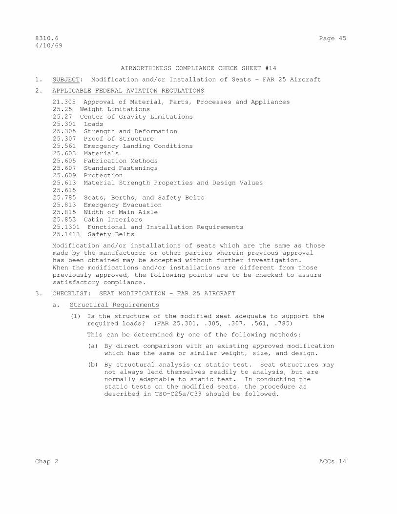
AIRWORTHINESS COMPLIANCE CHECK SHEET #14
1. SUBJECT : Modification and/or Installation of Seats – FAR 25 Aircraft
2. APPLICABLE FEDERAL AVIATION REGULATIONS
21.305 Approval of Material, Parts, Processes and Appliances 25.25 Weight Limitations 25.27 Center of Gravity Limitations 25.301 Loads 25.305 Strength and Deformation 25.307 Proof of Structure 25.561 Emergency Landing Conditions 25.603 Materials 25.605 Fabrication Methods 25.607 Standard Fastenings 25.609 Protection 25.613 Material Strength Properties and Design Values 25.615 25.785 Seats, Berths, and Safety Belts 25.813 Emergency Evacuation 25.815 Width of Main Aisle 25.853 Cabin Interiors 25.1301 Functional and Installation Requirements 25.1413 Safety Belts
Modification and/or installations of seats which are the same as those made by the manufacturer or other parties wherein previous approval has been obtained may be accepted without further investigation. When the modifications and/or installations are different from those previously approved, the following points are to be checked to assure satisfactory compliance.
3. CHECKLIST: SEAT MODIFICATION – FAR 25 AIRCRAFT
a. Structural Requirements
(1) Is the structure of the modified seat adequate to support the required loads? (FAR 25.301, .305, .307, .561, .785)
This can be determined by one of the following methods:
(a) By direct comparison with an existing approved modification which has the same or similar weight, size, and design.
(b) By structural analysis or static test. Seat structures may not always lend themselves readily to analysis, but are normally adaptable to static test. In conducting the static tests on the modified seats, the procedure as described in TSO-C25a/C39 should be followed.
Chap 2 ACCs 14
Page 46 8310.6 4/10/69
b. Hazards to Aircraft or its Occupants
(1) Does the modification affect the amount of padding or cush- ioning material so that corners, fittings, knobs, or similar projections are more likely to cause serious injury by human impact? (FAR 25.561 and 25.785.)
(2) Does change in fabric or upholstery material comply with flame- resistant requirements? (FAR 25.853)
(3) Does change adversely affect operating mechanism or other subcomponent of seat, in that it may effect the safety of occupant? (FAR 25.1301)
(4) Does the modification affect weight and balance of aircraft? (FAR 25.25, 25.27)
c. Detail Design Standards .
(1) Does change affect the strength of safety belt attachment? (FAR 253.1413)
(2) Does change to seat design or seat location have any effect regarding the access to emergency exit(s) or width of main passenger aisle? (FAR 25.813)
(3) Are acceptable government and industry standards followed with respect to: materials, fastenings, fabrication methods, protection of seat structure, and design criteria? (FAR 25.603, .605, .607, .613, .615) (See also TSO-C25a/C39)
4. CHECKLIST: SEAT INSTALLATION – FAR 25 AIRCRAFT
a. Structural Requirements
(1) Is the seat to be installed an approved seat which complies with the requirements of TSO-C25a/C39? (FAR 21.305, 25.785)
(2) If the seat has been manufactured to conform with TSO require- ments, has the strength of seat attachment to structure been determined by using the factor of 1.33 times (multiplied by) the acceleration loads prescribed by FAR 25.561? (FAR 25.785)
(3) If the seat does not have TSO approval and is thus being approved as part of the aircraft, are the seat structure and the strength of the seat attachment adequate to support the required loads? (FAR 25.561, 25.785, 25.301, 25.305, and 25.307.
ACCS 14 Chap 2

8310.6 Page 47 (and 48) 4/10/69
This can be determined by the application of loads as described in FAR 25.785. In conducting the static tests on the seat and seat attachment to structure, the procedure as described in TSO-C25a/C39 should be followed.
b. Hazards to the Aircraft or its Occupants
(1) Does the seat installation create any hazard to other passengers or can it contribute to a serious injury in the event of a minor crash landing? (FAR 25.561 and 25.1413)
(2) Has it been demonstrated that the seat installation functions properly in the airplane? (FAR 25.1301)
(3) Has the weight and balance effect of the seat installation been considered? (FAR 25.25, 25.27)
(4) Does the seat installation have any adverse effect regarding the access to emergency exit(s) or width of the main passenger aisle? (FAR 25.813 and 25.815)
c. Detail Design Standards
(1) If the seat does not have TSO approval, do the design standards comply with approved requirements? (FAR 25.785)
Chap 2 ACCS 14

8310.6 Page 49 4/10/69
AIRWORTHINESS COMPLIANCE CHECK SHEET #15
1. SUBJECT : Landing Light Installations – FAR 23 Aircraft
2. APPLICABLE FEDERAL AVIATION REGULATIONS
23.301 Loads 23.307 Proof of Structure 23.337 Maneuvering Load Factors 23.341 Gust Load Factors 23.473 Load Factor for Landing Conditions 23.603 Material and Workmanship 23.605 Fabrication Methods 23.607 Standard Fastenings 23.609 Protection 23.611 Inspection Provisions 23.1301 Functional and Installational Requirements 23.1351 Electrical System Installation
Generator
23.1357 Fuses or Circuit Breakers 23.1361 Master Switch Arrangement 23.1383 Landing Lights
Landing Light Installations
91.33 An electric landing light is required by the operating rule (FAR 91.33) only when (1) the aircraft is operated for hire and (2) the aircraft is operated at night or under IFR. Landing light installations which are the same as those made by the airframe manufacturer or other installations which are already approved, may be accepted without further investiga- tion. On other installations, the following points should be checked to determine that the installation is satisfactory.
3. CHECKLIST
a. Structural Requirements :
(1) Is the installation capable of withstanding the required loads? The effect on other structure (primary or secondary) should be considered. (FAR’s 23.301, 23.337, 23.341, and 23.473.)
NOTE: Particular care should be taken on the installation of landing lights since they are usually recessed into existing structure in the wing or fuselage. The leading edges of stress skinned (and some fabric covered) wings are usually structural to a large degree and would be adversely affected by cutouts which are not sufficiently or correctly reinforced. While the extreme nose sections
Chap 2 ACCS 15

Page 50 8310.6 4/10/69
Of the fuselage are usually not primary structure, care should be taken on these installations. It is recommended if there is any doubt as to whether the proposed installa- tion in the wing or fuselage is affecting primary or secondary structure, that the Engineering Service Representative be contacted for assistance. It is fur- ther recommended if the structure is definitely primary that the Engineering Service Representative be contacted for assistance in the evaluation of the installation.
(2) Is the material used in the installation suitable for the purpose intended and is the workmanship of a high standard? (FAR 23.603.)
(3) Will the fabrication methods used result in a consistently sound installation and are standard approved fasteners used? (FAR 23.605, and 23.607.)
(4) Is adequate protection provided to protect against deterioration or loss of strength in service due to weathering, abrasion or other causes? Are adequate inspection means provided and will the installations have an adverse effect on the inspection provisions for other components of the aircraft? (FARs 23.609, and 23.1383.)
b. Hazards to the Aircraft or its Occupants :
(1) Is the pilot compartment free from dangerous glare, halations or reflections which would interfere with the pilot’s vision during operation of the landing light? (FAR 23.1383.)
A night-flight check should be performed to assure that no interference with pilot vision exists. Reflections from the propeller disc are particularly troublesome.
(2) Is a fuse or circuit breaker of the rating appropriate to the cable used installed? (FAR 23.1357.)
(3) If a circuit breaker is used, is it of a type which will open the circuit irrespective of the position of the control in case of a fault? (FAR 23.1357.)
(4) Are the connecting cables in accordance with recognized standards for electric cable of a slow-burning type? (Cable conforming to military specification MIL-W-5086 or the equivalent is acceptable.) (FAR 23.1365.)
c. Operating Aspects:
(1) Does the landing light provide sufficient properly directed runway illumination to permit safe landings during night VFR operations? (FAR 23.1383.)
ACCS 15 Chap 2

8310.6 Page 51(and 52) 4/10/69
NOTE: A night-flight check should be performed to check landing light effectiveness.
(2) Is the landing light switch located so as to be readily accessible to the pilot? (FAR 23.1301.)
(3) Is the landing light switch adequately labeled as to operation and function performed? (FAR 23.1301.)
d. Detail Design Standards :
(1) Are the electric cables for the landing light installed in such a manner that they are suitably protected from fuel, oil, water and other detrimental substances, and mechanical damage? (FAR 23.1351.)
(2) Is the circuit to the landing light connected through the master switch arrangement? (FAR 23.1361.)
NOTE: A flight check should be performed to determine possible adverse flight characteristics with light in extended position.
Chap 2 ACCS 15

8310.6 Page 53 4/10/69
AIRWORTHINESS COMPLIANCE CHECK SHEET #16
1. SUBJECT : Landing Light Installations – FAR 25 Aircraft
2. APPLICABLE FEDERAL AVIATION REGULATIONS
21.305 Approval of Materials, Parts, Processes and Appliances 25.301 Loads 25.305 Strength and Deformation 25.307 Proof of Structure 25.321 Flight Loads .331 .333 .337 .341 .349 .351 25.471 Ground Loads .473 25.561 Emergency Landing Conditions 25.603 Materials 25.605 Fabrication Methods 25.607 Standard Fastenings 25.609 Protection 25.611 Inspection Provisions 25.613 Material Strength Properties and Design Values 25.1301 Functional and Installational Requirements 25.1309 Equipment, Systems and Installations 25.1351 Electrical System Capacity 25.1353 Electrical Equipment and Installations 25.1357 Electrical Protection 25.1363 Electrical System Tests and Analyses 25.1383 Landing Lights
Landing light installations which are the same as those made by the airframe manufacturer or other installations which are already approved, may be accepted without further investigation. On other installations, the following points should be checked to determine that the installation is satisfactory.
3. CHECKLIST
a. Structural Requirements :
(1) Is the installation capable of withstanding the required loads? The effect on other structure (primary or secondary) should be considered. (FARs 25.301, .305, .307, .321,.331, .333, .337, .341, .349, .351, .471, .473, .561.)
Particular care should be taken on the installation of landing lights since they are usually recessed into existing structure in
Chap 2 ACCS 16

Page 54 8310.6 4/10/69
the wing or fuselage. The leading edges of stress skinned wings are usually structural to a large degree and would be adversely affected by cutouts which are not sufficiently or correctly reinforced. While the extreme nose sections of fuselage are usually not primary structure, care should be taken on these installations. It is recommended if there is any doubt as to whether the proposed installation in the wing or fuselage is affecting primary or secondary structure, that the Engineering Service Representative be contacted for assistance. It is further recommended if the structure is definitely primary that the ESR be contacted for assistance in the evaluation of the installation.
(2) Is the material used in the installations suitable for the purpose intended and is the workmanship of a high standard? (FAR 21.305, 25.603, 25.613.)
(3) Will the fabrication methods used result in a consistently sound installation and are standard approved fasteners used? (FAR 25.603, 25.605, 25.607.)
(4) Is adequate protection provided to protect against deterioration or loss of strength in service due to weathering, abrasion or other causes? Are adequate inspection means provided and will the installations have an adverse effect on the inspection provisions for other components of the aircraft? (FAR 25.609, 25.611.)
b. Hazards to the Aircraft or its Occupants
(1) Are the landing lights so installed that there is no glare, reflection, or halation which would interfere with the pilot’s vision during operation of the lights? (FAR 25.1383)
Note: A night flight check should be performed to assure that no interference with pilot vision exists. Reflection from the propeller discs is particularly troublesome.
(2) Is a fuse or circuit breaker of appropriate rating to protect the cable installed in the landing light circuit? (FAR 25.1357.)
(3) If a circuit breaker is used, it is of a type which will open the circuit irrespective of the position of the control in case of a fault? (FAR 25.1357.)
ACCS 16 Chap 2

8310.6 Page 55(and 56) 4/10/69
(4) Are the cables to the landing lights so installed that damage to essential circuits will be minimized in the event of a fault in a landing light cable? (FAR 25.1353.)
c. Operating Aspects
(1) Are the landing lights so installed that they provide sufficient illumination to permit safe landings during night VFR operations? (FAR 25.1383)
Note: A night flight check should be performed to check landing light effectiveness.
(2) Are the landing light switches readily accessible to the crew and suitably labeled as to operation and function performed? (FAR 25.1301)
(3) Is a separate switch provided for each landing light? (FAR 25.1383.)
Note: If two or more lights are installed in each wing, a switch for each set of lights is acceptable.
(4) Is a means provided to indicate to the pilots when the landing lights are extended? (FAR 25.1383)
d. Detailed Design Standards
(1) Are the landing lights and cables capable of withstanding critical environmental conditions? (Cable conforming to Military Specification MIL-W-5086 or the equivalent is acceptable.) (FAR 25.1353)
(2) Are the landing lights and cables so installed and designed that operation of the lights will not affect adversely the operation of any other unit or system of units essential to the safe operation of the airplane? (FAR 25.1353)
(3) Is the electric power system capable of supplying the added lighting load without electrical or thermal distress? This may be determined by revision of the original load analysis, conducting a new load analysis, or by actual flight or ground tests. In any case, it should be determined that the system is not overloaded. (FAR 25.1309, 25.1351, 25.1363)
Chap 2 ACCS 16
8310.6 Page 57 4/10/69
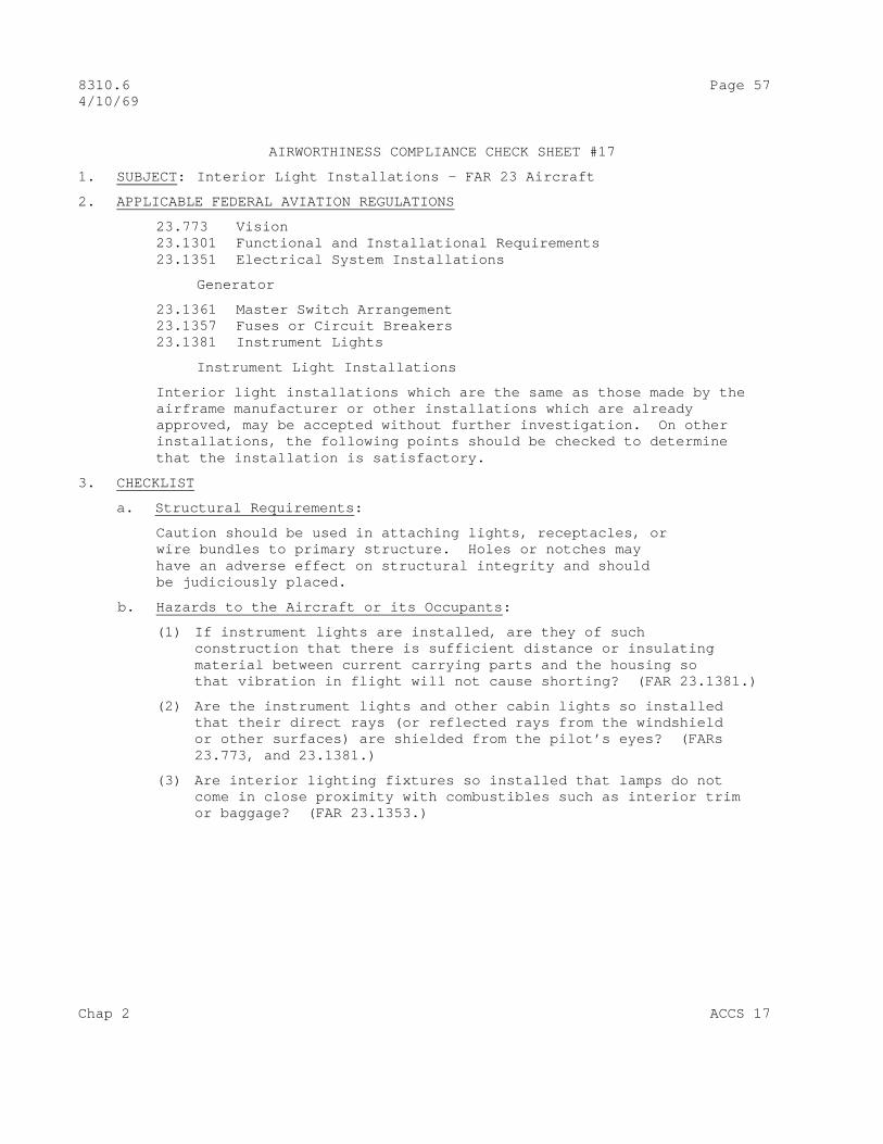
AIRWORTHINESS COMPLIANCE CHECK SHEET #17
1. SUBJECT : Interior Light Installations – FAR 23 Aircraft
2. APPLICABLE FEDERAL AVIATION REGULATIONS
23.773 Vision 23.1301 Functional and Installational Requirements 23.1351 Electrical System Installations
Generator
23.1361 Master Switch Arrangement 23.1357 Fuses or Circuit Breakers 23.1381 Instrument Lights
Instrument Light Installations
Interior light installations which are the same as those made by the airframe manufacturer or other installations which are already approved, may be accepted without further investigation. On other installations, the following points should be checked to determine that the installation is satisfactory.
3. CHECKLIST
a. Structural Requirements :
Caution should be used in attaching lights, receptacles, or wire bundles to primary structure. Holes or notches may have an adverse effect on structural integrity and should be judiciously placed.
b. Hazards to the Aircraft or its Occupants :
(1) If instrument lights are installed, are they of such construction that there is sufficient distance or insulating material between current carrying parts and the housing so that vibration in flight will not cause shorting? (FAR 23.1381.)
(2) Are the instrument lights and other cabin lights so installed that their direct rays (or reflected rays from the windshield or other surfaces) are shielded from the pilot’s eyes? (FARs 23.773, and 23.1381.)
(3) Are interior lighting fixtures so installed that lamps do not come in close proximity with combustibles such as interior trim or baggage? (FAR 23.1353.)
Chap 2 ACCS 17

Page 58 8310.6 4/10/69
(4) Is a fuse or circuit breaker of the rating appropriate to the cable used installed? (FAR 23.1357.)
(5) If a circuit breaker is used, is it of a type which will open the circuit irrespective of the position of the control in case of a fault? (FAR 23.1357.)
(6) Are the connecting cables in accordance with recognized stan- dards for electric cable of a slow-burning type? (Cable conforming to military specification MIL-W-5086 or the equivalent is acceptable.) (FAR 23.1365.)
c. Operating Aspects :
(1) If instrument lights are installed, do they provide sufficient illumination to make all instruments and controls easily readable and discernible? (FAR 23.1381.)
(2) Are all interior lighting switches (which are significant to safety) readily accessible to the pilot and suitably labeled as to operation and function performed? (FAR 23.1301.)
d. Detail Design Standards :
(1) Are the electric cables for the interior lights installed in such a manner that they are suitably protected from fuel, oil, water and other detrimental substances, and mechanical damage? (FAR 23.1351.)
(2) Is the circuit to all interior lights connected through the master switch arrangement? (FAR 23.1361.)
(3) Output ratings should be compared to maximum probable loads per AC 43.13-1, paragraph 238. (FAR 23.1351.)
ACCS 17 Chap 2
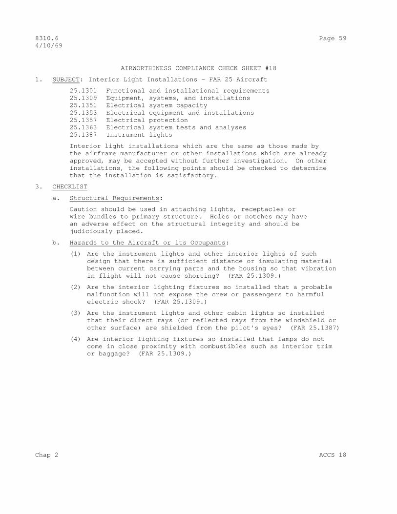
8310.6 Page 59 4/10/69
AIRWORTHINESS COMPLIANCE CHECK SHEET #18
1. SUBJECT : Interior Light Installations – FAR 25 Aircraft
25.1301 Functional and installational requirements 25.1309 Equipment, systems, and installations 25.1351 Electrical system capacity 25.1353 Electrical equipment and installations 25.1357 Electrical protection 25.1363 Electrical system tests and analyses 25.1387 Instrument lights
Interior light installations which are the same as those made by the airframe manufacturer or other installations which are already approved, may be accepted without further investigation. On other installations, the following points should be checked to determine that the installation is satisfactory.
3. CHECKLIST
a. Structural Requirements :
Caution should be used in attaching lights, receptacles or wire bundles to primary structure. Holes or notches may have an adverse effect on the structural integrity and should be judiciously placed.
b. Hazards to the Aircraft or its Occupants :
(1) Are the instrument lights and other interior lights of such design that there is sufficient distance or insulating material between current carrying parts and the housing so that vibration in flight will not cause shorting? (FAR 25.1309.)
(2) Are the interior lighting fixtures so installed that a probable malfunction will not expose the crew or passengers to harmful electric shock? (FAR 25.1309.)
(3) Are the instrument lights and other cabin lights so installed that their direct rays (or reflected rays from the windshield or other surface) are shielded from the pilot’s eyes? (FAR 25.1387)
(4) Are interior lighting fixtures so installed that lamps do not come in close proximity with combustibles such as interior trim or baggage? (FAR 25.1309.)
Chap 2 ACCS 18
Page 60 8310.6 4/10/69
(5) Is a fuse or circuit breaker, of appropriate rating to protect the cable, installed in the lighting circuit? (FAR 25.1357.)
(6) If a circuit breaker is used, is it of a type which will open the circuit irrespective of the position of the control in case of a fault? (FAR 25.1357.)
c. Operating Aspects :
(1) Are the instrument lights so installed that they provide sufficient illumination to make all instruments and switches easily readable? (FAR 25.1387.)
(2) Is a means of controlling the intensity of the instrument lights provided, except where it can be shown that nondimmed lights are satisfactory under all expected conditions of flight? (FAR 25.1387.)
(3) Are all interior lighting switches (which are significant to safety) readily accessible to the crew and suitably labeled as to operation and function performed? (FAR 25.1301.)
c. Detail Design Standards :
(1) Are all lighting fixtures and cables capable of withstanding critical environmental conditions? (Cable conforming to Military Specification MIL-W-5086 or the equivalent is acceptable). (FAR 25.1353.)
(2) Are all lights and cables so installed that the operation of any one unit or system of units will not affect adversely the simultaneous operation of any other electrical unit or system or units essential to the safe operation of the airplane? (FAR 25.1353.)
(3) Is the electric power system capable of supplying the added lighting load without electrical or thermal distress?
This may be determined by revision of the original load analysis, conducting a new load analysis, or by actual flight tests. In any case, it should be determined that the system is not overloaded. (FARs 25.1309, 25.1351, and 25.1363.)
ACCS 18 Chap 2

8310.6 Page 61 4/10/69
AIRWORTHINESS COMPLIANCE CHECK SHEET #19
1. SUBJECT : Anticollision Light Installations – FAR 25 Aircraft
2. APPLICABLE FEDERAL AVIATION REGULATIONS
25.301 Loads 25.305 Strength and Deformation 25.307 Proof of Structure 25.321 Flight Loads 25.417 Ground Loads 25.561 Emergency Landing Conditions 25.603 Materials 25.605 Fabrication Methods 25.607 Standard Fastenings 25.609 Protection 25.611 Inspection Provisions 25.629 Flutter, Deformation and Vibration 25.773 Pilot Compartment Vision 25.1309 Equipment Systems and Installations 25.1353 Electrical Equipment and Installations 25.1357 Electrical Protection 25.1401 Anticollision Light System
Anticollison light installations which are the same as those made by the airframe manufacturer, or their installations which are already approved, may be accepted without further investigation. On other installations, the following points should be checked to determine that the installation is satisfactory. The existing anticollision system requirements in FAR 25.1401 were effective April 1, 1957, and, therefore, apply only to aircraft for which an application for a type certificate was made on or after that date. Anticollision lights now installed on earlier aircraft (for which application for a type certificate was made before April 1, 1957) do not necessarily comply with latest regulation. The information contained in AC 43.13-2, Chapter 4, may be used in evaluating anticollision light modifications on such aircraft. The material below should be used when the applicant is required to ( or elects to) comply with the existing requirements.
3. CHECKLIST .
a. Structural Requirements :
(1) Is the installation capable of withstanding the required loads? The effect on other structure (primary or secondary) should be considered. (FARs 25.301, 25.305, 25.307, 25.321. 25.471 and 25.561)
NOTE: The information contained in AC 43.13-2, Chapter 4, may be used for assistance in determining compliance. For
Chap 2 ACCS 19

Page 62 8310.6 4/10/69
installation involving cutting of pressurized fuselage structure or fin and rudder installations, the regional Engineering Service Representative should be contacted for assistance in the evaluation.
(2) Will the installation affect the flutter and vibration characteristics of the aircraft? (FAR 25.629)
NOTE: The regional Engineering Service Representative should be contacted for assistance in evaluating this installation, particularly if it involves the fin, rudder, or top of fuselage just forward of the fin.
b. Hazards to the Aircraft or its Occupants :
(1) Are the anticollision lights so located that their output is not detrimental to the flight crew’s vision? (FARs 25.773 and 25.1401)
NOTE: A night-flight check should be performed to determine that there are no hazardous reflections from such sources as the propeller discs, nacelles or wing surfaces.
(2) Are the anticollision lights so located that they do not detract from the conspicuity of the position lights? (FAR 25.1401.)
(3) Is a fuse or circuit breaker (of a rating appropriate to the cable used) installed? (FAR 25.1357.)
(4) If a circuit breaker is used, is it of a type which will open the circuit irrespective of the position of the control, in case of a fault? (FAR 25.1357)
c. Operating Aspects :
(1) Does the system illuminate in all directions within 30 ° above and 30° below the horizontal plane of the aircraft, except for a solid angle obstructed visibility not exceeding 0.03 steradians in the rearward direction? (FAR 25.1401) A relatively simple method to determine the solid angle obstruction due to the tail fin is as follows:
(a) Position the levelled aircraft in a darkened hangar so that its longitudinal axis is perpendicular to the hangar wall. Place a small light at the desired top anticollision light location. Measure the areas of the tail fin shadow on the wall above the height of the lamp. This area, divided by the square of the distance from lamp to wall (in the same units), is approximately equal to the solid angle obstruc- tion in steradians. The distance from lamp to wall should be as large as practicable to keep errors low.
ACCS 19 Chap 2
8310.6 Page 63(and 64) 4/10/69
(2) Is the obstructed visibility (if any) confined within a solid angle equal to 0.15 steradians centered about the longitudinal axis of the aircraft in the reaward direction? (FAR 25.1401) (See information under paragraph (1) above on measurements of steradians.)
(3) Is the effective flash frequency of the anticollision light system, as observed from a distance, between 40 and 100 cycles per minute? (FAR 25.1401)
(4) If the anticollision light system is made up of two or more individual lights, is the effective flash frequency less that 180 cycles per minute in the overlap regions? (FAR 25.1401)
(5) Is the color of the lights aviation red in accordance with the specifications of FAR 25.1397? (FAR 25.1401) (Pending issuance of a TSO on these lights, light manufacturers’ or other laboratory test reports may be acceptable as proof of color)
(6) Are the minimum light intensities in all vertical planes measured with the red filter and expressed in terms of “effective intensities”, in accordance with Figure 25.1401? (FAR 25.1401)
d. Detail Design Standards :
(1) Are the lights and wiring components designed to withstand probable environmental extremes (of temperature, vibration, pressure, etc.) to which they could be exposed?
(2) Are approved materials used in the installation, including standard fastenings? (FARs 25.603, 25.607)
(3) Will the fabrication methods used result in a consistently sound structure? (FAR 25.605)
(4) Is the installation protected against deterioration due to weathering, corrosion, abrasion or other causes? (FAR 25.609)
(5) Are adequate inspection provisions made for this and other affected components? (FAR 25.611)
Chap 2 ACCS 19

8310.6 Page 65 4/10/69
AIRWORTHINESS COMPLIANCE CHECK SHEET #20
1. SUBJECT : Buffet and Cabinet Installations – FAR 23 Aircraft
2. APPLICABLE FEDERAL AVIATION REGULATIONS
23.23 Weight and Balance 23.301 Loads 23.307 Proof of Structure 23.337 Maneuvering Load Factors 23.341 Gust Load Factors 23.473 Load Factor for Landing Conditions 23.521 Water Load Conditions 23.561 Protection 23.603 Material and Workmanship 23.605 Fabrication Methods 23.607 Standards Fastenings 23.609 Protection 23.611 Inspection Provisions 23.613 Material Strength Properties and Design Values 23.807 Exits 23.1301 Functional and Installation Requirements 23.1431 23.1557 Baggage Compartment – Limitations 23.1589 Center of Gravity Position
Since FAR 23 design requirements do not adequately provide for buffet and cabinet installation, the following check list is intended to be used as guidance material when approving buffet and cabinet installations and is also to be used when approving modifications to existing buffet and cabinet installations.
3. CHECKLIST
a. Structural Requirements :
(1) Is the structure adequate to support the required loads? (FARs 23.301, 23.307, 23.337, 23.341, 23.473, 23.521, 23.561, and 23.23.)
This answer can be determined by either of two methods:
(a) By direct comparison with an existing approved installation having the same or similar characteristics of weight, size, and arrangement.
(b) By structural analysis or static test. Structures, such as buffets and cabinets, do not lend themselves readily to analysis but are normally adaptable to static test.
Chap 2 ACCS 20
Page 66 8310.6 4/10/69
In conduction the static test, the following procedure may be used:
1 Determine the weight and center of gravity position of the complete assembly to be tested.
2 Mount the unit either in its position in the airplane or in a rig simulating the actual installation in the airplane.
3 Dummy equipment items simulating the actual buffet units should be installed utilizing the attaching points by which the equipment is normally held in place. The dummy equipment should be such that the required loads can be applied at the c.g. position of the actual equipment.
4 The required loads should then be applied by any suitable means.
In accordance with FAR 23.561, all items of mass which would be apt to injure the passengers or crew in the event of a minor crash landing should have their supporting structure designed to the crash load requirements of (FAR 23.561) insofar as the forward, upward, and sideward direction are concerned. The applicable downward load factor shall be the critical flight or landing load factor specified in FAR 23.337, 23.341, and 23.473. In lieu of a calculated determination of the down load factor, the ultimate factors of 6.6, 6.6, and 9.0 may be used for the normal, utility, and acrobatic categories, respectively. For equipment locations not covered by FAR 23.561, the required loads (ref. FAR 23.301) are the flight and landing load factors of FARs 23.337, 23.341, and 23.473. In lieu of a calculated determination of these loads, the load factors of 23.561 plus the down load factors referenced above may be used.
(2) Is the buffet or cabinet installed so that it does not adversely affect other structure, either primary or secondary? (FAR 23.1431.)
(3) If the buffet or cabinet is installed in a compartment which has a placarded weight limitation, has this placard been changed to reflect the weight of the added equipment? (FAR 23.1557.)
ACCS 20 Chap 2

8310.6 Page 67(and 68) 4/10/69
b. Hazards to the Aircraft or its Occupants :
(1) As the result of the buffet or cabinet being installed, is the accessibility of the exits and doors adversely affected? (FAR 23.807.)
(2) Will an occupant, when making proper use of the safety belt, receive possible serious injury during minor crash conditions as the result of contact of his body with protruding or penetrating parts of the buffet or cabinet? (FAR 23.561.)
c. Detail Design Standards :
(1) Will the installation of the buffet or cabinet, and their contents, adversely affect the weight and balance of the airplane for the most forward and most aft c.g. locations? (FARs 23.23 and 23.1589.)
Electrical aspects of buffet and cabinet installations are the subject of another ACCS.
Chap 2 ACCS 20

8310.6 Page 69 4/10/69
AIRWORTHINESS COMPLIANCE CHECK SHEET #21
1. SUBJECT : Buffet and Cabinet Installations – FAR 25 Aircraft
2. APPLICABLE FEDERAL AVIATION REGULATIONS
21.305 Approval of Material, Parts, Processes, and Appliances 25.301 Loads 25.303 Loads 25.305 Strength and Deformation 25.307 Proof of Structure 25.321 Flight Loads 25.365 Flight Loads 25.367 Flight Loads 25.373 Flight Loads 25.471 Ground Loads 25.473 Ground Loads 25.489 Ground Loads 25.491 Ground Loads 25.499 Ground Loads 25.503 Ground Loads 25.507 Ground Loads 25.511 Ground Loads 25.561 Emergency Landing Conditions 25.603 Materials 25.605 Fabrication Methods 25.607 Standard Fastenings 25.609 Protection 25.611 Inspection Provisions 25.615 Material Strength Properties and Design Values 25.813 Emergency Evacuation 25.1301 Functional and Installation Requirements 25.1309 Equipment, Systems, and Installations 25.1353 Electrical Equipment and Installations 25.1583 Operating Limitations
Buffet and cabinet installations which are the same as those made by the airframe manufacturer or other installations which are already approved may be accepted without further investigation. On other installations, the following points should be checked to determine that the installation is satisfactory.
3. CHECKLIST :
a. Structural Requirements
(1) Is the structure adequate to support the required loads? (FARs 25.301, 25.303, 25.305, 25.307, 25.321, 25.365, 25.367, 25.373, 25.471, 25.473, 25.489, 25.491, 25.499, 25.503, 25.507, 25.511, 25.561)
Chap 2 ACCS 21

Page 70 8310.6
4/10/69
This answer can be determined by either of two methods:
(a) By direct comparison with an existing approved installation having the same or similar characteristics of weight, size and arrangement.
(b) By structural analysis or static test. Structures, such as buffets and cabinets, do not lend themselves readily to analysis, but are normally adaptable to static test. In conducting the static test the following procedure may be used:
1 Determine the weight and center of gravity position of the complete assembly to be tested.
2 Mount the unit either in its position in the airplane or in a rig simulating the actual installation insofar as attachments to the airplane are concerned.
3 Dummy equipment items simulating the actual buffet units should be installed utilizing the attaching points by which the equipment is normally held in place. The dummy equipment should be so that the required loads can be applied at the c.g. position of the actual equipment.
4 The required loads should then be applied by any suitable means.
All items of mass which would be apt to injure the passengers or crew in the event of a crash landing should have their supporting structure designed to the crash load requirements of FAR 25.561.
Other mass items should have their supporting structure designed to the critical load factors of FARs 25.321, 25.365, 25.367, 25.373, 25.471, 25.473, 25.489, 25.491, 25.499, 25.503, 25.507, 25.511. The load factors of 25.561 may be used in lieu of these factors.
(2) Is the buffet or cabinet installed in such a manner so that it does not adversely affect other structure, either primary or secondary? (FAR 25.307)
b. Hazards to the Aircraft or its Components
(1) As the result of the buffet or cabinet being installed, is the accessibility of the exits and doors adversely affected? (FAR 25.813)
ACCS 21 Chap 2
8310.6 Page 71(and 72) 4/10/69
(2) Will an occupant, when making proper use of the safety belt, receive possible serious injury during minor crash conditions as the result of contact of his body with protruding or penetrating parts of the buffet or cabinet? (FAR 25.561)
(3) Is the installation and surrounding area suitably protected to prevent corrosion resulting from spillage of corrosive liquids in the vicinity of the buffet? (FAR 25.609)
c. Detail Design Standards
(1) Will the installation of the buffet or cabinet, and their contents, adversely affect the weight and balance of the airplane? (FAR 25.1583)
(2) Are the locks and catches on each of the doors adequate to retain the buffet units stored within during emergency landing and severe gust conditions? (FAR 25.305)
(3) Are the materials used suitable for the purpose intended and the method of fabrication such that it will result in a consistently sound structure? (FAR 25.607, 25.615, 21.305, 25.603, 25.605)
(4) Are satisfactory inspection means provided for the installation and the surrounding area? (FAR 25.611)
The electrical aspects of these installations will be covered in another ACCS.
Chap 2 ACCS 21

8310.6 Page 73 4/10/69
AIRWORTHINESS COMPLIANCE CHECK SHEET #22
1. SUBJECT : Installations or Modifications of Windshields With or Without Electrical Heating Provisions in Nonpressurized Aircraft (FAR 23)
2. INTRODUCTION : These guidelines are applicable to windshields in non- pressurized airplanes. Windshield installations which are the same as those made by the airframe manufacturer or other installations on the same type aircraft which are already approved may be accepted without further investigation. If the installation involves modification of the basic aircraft structure, (e.g., acrylic plastic replaced with polyester or plastic replaced by glass or glass replaced by plastic), a change in material thickness or method of mounting, then extreme caution should be used in the evaluation. Hidden details may affect such installations to a considerable extent, such as the method of containing the glass or plastic.
3. APPLICABLE FEDERAL AVIATION REGULATIONS
23.301 Loads 23.307 Proof of Structure 23.321 Flight Loads 23.347 Flight Loads 23.471 Ground Loads 23.603 Materials and Workmanship 23.605 Fabrication Methods 23.607 Standard Fastenings 23.613 Material Strength Properties and Design Values 23.773 Vision 23.775 Windshields, Windows, and Canopies 23.777 Cockpit Controls 23.1351 Installation
Electric Power Sources
23.1357 Protective Devices Installation
Spare Fuses
23.1361 Master Switch Arrangement 23.1367 Switches
Switch Installation
4. CHECKLIST
a. Structural Requirements :
Chap 2 ACCS 22
Page 74 8310.6 4/10/69
(1) Can the windshield and its supporting structure support the required loads? (FARs 23.301, 23.307, 23.321, 23.347, and 23.471.)
NOTE: The windshield is generally free-floating and nonload- bearing except for aerodynamic loads. Therefore, these requirements would only be of concern if the windshield opening is change, if heat is used, or any appreciable change is made in the windshield thickness. Modifications, where it can be determined that equivalent or better structure has been installed, may be accepted after satisfactory completion of a test to Vne. This test should be conducted with caution and the speed Vne approached gradually. If the panel incorporates deicing or defogging provisions, the test should be performed with the windshield heat turned on, since the windshield interlayer material is more flexible at the higher tem- peratures.
If some doubt exists or if the installation is quite com- plex, the Engineering Service Representative should be contacted.
b. Hazards to the Aircraft or its Occupants :
(1) All internal glass panes shall be of a nonsplintering safety type. This would preclude the use of glass on the pilot side which is not a laminate of glass and plastic. (FAR 23.775.)
(2) If the windshield is electrically heated, is the electrical means properly protected by being laminated within the panel? (FAR 23.1351.)
(3) Are power leads, terminal attachments, and insulating covers installed so that they properly protect the pilot and copilot during a power-on condition? (FAR 23.1351.)
(4) Is power supply system properly safeguarded and electrically sound and adequate? Check the electrical system to the wind- shield for fuses, proper wire diameters, and specifications. (FARs 23.1351, 23.1361, 23.1357, and 23.1367.)
(5) Is there a cycling indicator to show power-on condition? (FAR 23.1351.)
(6) If the windshield draws 2 or more watts per square inch in any portion of the heated area, is there a temperature control system?
ACCS 22 Chap 2

8310.6 Page 75 4/10/69
NOTE: Windshields drawing 2 watts per square inch of heated area or more may become excessively overheated. The control system should be adjusted to provide a nominal temperature of 100 °F. at the sensing element control. This may be accomplished by checking that the temperature on the outside of the windshield does not exceed 100 °F. when measured in still air with a thermocouple or thermometer.
It is acceptable to operate one or more similar panels from one control system turning all “on” and “off”, with a temperature sensor in one panel. An interruption in any part of the circuit should cause the system to turn off power to all the windshield panels. The panels should be similar electrically and should have essentially the same heat output within reasonable tolerance limits.
(7) Is the magnetic compass or other instruments and equipment such as radio unaffected when the power is applied to the windshield? (FAR 23.1351.)
c. Operating Aspects :
(1) Is the pilot’s view through the windshield sufficiently extensive, clear, and undistorted for safe operation of the airplane, particularly during a moderate rain condition? (FAR 23.773.)
NOTE: FAR 23.773 should be reviewed in this evaluation. For aircraft intended for night operation a flight test is required. This should be performed with heat on for deicing or defogging panels. (FAR 23.1351.)
(2) Do the windshields and side windows have a luminous trans- mittance value of not less than 70 percent? This applies only to those panels which are forward of the pilot’s back when he is seated in normal flight position. (FAR 23.775.)
NOTE: If the windshield is not certified by the manufacturer as meeting the 70 percent luminous transmittance value, Federal Test Method Standard No. 406, Method 3022, or American Society for Testing Materials No. D 1003-52 can be used to determine the value. If the material is manufactured to a military specification, the luminous transmittance value may be read from the specification for the particular thickness used.
(3) Is the windshield heat switch within convenient reach of the pilot or copilot? (FAR 23.777.)
Chap 2 ACCS 22

Page 76 8310.6 4/10/69
d. Detail Design Standards :
(1) Has experience or a test established the suitability and durability of the material being used? (FAR 23.603.)
NOTE: A plastic windshield may be replaced with another plastic material, or glass with glass, provided the materials are of the same type and quality and the dimensions are unchanged. If plastic is to be replaced by glass or if the reverse occurs, it is a new installation and should be reviewed per the note under Section 4.(1). The mechan- ical means of attachment may be critical.
(2) Do the materials conform to approved specifications? (FAR 23.603)
(3) Will the method of fabrication result in a consistently sound structure? (FAR 23.605.)
NOTE: Panel edges and any fastener holes should be smooth and without nicks. Laminated parts should have Parts Manufacturer approval.
(4) Are standard approved fasteners used? (FAR 23.607.)
ACCS 22 Chap 2

8310.6 Page 77 4/10/69
AIRWORTHINESS COMPLIANCE CHECK SHEET #23
1. SUBJECT : Modifications of an Exhaust Type Cabin Heater to Increase Heat Output Without any Changes to the Existing Exhaust System – FAR 23 Aircraft.
2. APPLICABLE FEDERAL AVIATION REGULATIONS
23.1125 Exhaust Heat Exchangers, Exhaust Heat Exchangers Used in Ventilating Air Heating Systems 23.1141 Powerplant Controls 23.831 Ventilation
The type of heater under consideration is a simple muff type assembly which encloses a portion of the exhaust manifold. Since the change being evaluated does not involve any modification of the exhaust manifold, these guidelines do not cover exhaust system changes. Inspector should refer to pertinent ACCS if exhaust system changes are involved.
3. CHECKLIST
a. Structural :
(1) Is the heater assembly constructed and supported to withstand vibration, inertia, and other loads which might be imposed during normal operation? (FAR 23.1125)
b. Hazards :
(1) Are the design and construction features of the heater such as to prevent the leakage of exhaust gases from joints or discharge points into the ventilating are? (FAR 23.1125)
(2) Is the ventilating air intake so located as to prevent the entrance of fumes or fluids from any source? (FAR 23.1125)
NOTE: Watch out for areas where breathers, drains or exhaust discharge.
c. Operational :
(1) Do the heater controls maintain their setting with the engine running? (FAR 23.1141)
(2) Do controls have adequate strength and rigidity to withstand operational loads? (FAR 23.1141)
Chap 2 ACCS 23

Page 78 8310.6 4/10/69
(3) Has every possible source of carbon monoxide contamination of cabin air been investigated and corrected? (FAR 23.831)
NOTE: If there is any evidence or suspicion that carbon monoxide might enter the cabin ventilating air, the Engineering Service Representative should be contacted to conduct a flight test. Carbon monoxide concentration shall not exceed one part in 20,000 parts of air, same as ACCS on engine exhaust system.
Test Procedure to Determine CO Content
A carbon monoxide indicator should be used in determining compliance with the above requirement. The instrument manufactured by the Mines Safety Appliance Company or the Bulb type Colorimetric Indicator may be used for this purpose, one of which is located at each Flight Engineering and Factory Inspection Branch Office. The following procedure should be used:
a The aircraft should be flown in level flight at MC power or as nearly so as possible. Carburetor should be set full rich with all windows closed; reading should be taken in at least the following locations:
1 Along the floor (approximately 4 inches above) in front of each occupant.
2 On each side of the cabin approximately a foot forward of each occupant.
3 A few inches in front of each occupants face.
4 In front of the cabin heater opening(s) with heat on.
b Conduct the same investigation as outlined in a 1 through a 3 except with window partially open, thus tending to produce a vacuum in the cabin.
c The aircraft should then be flown in a glide with power off (idling) and readings taken a few inches in front of each occupant’s face with both windows open and closed as above.
d The highest reading obtained at any of the above points shall not exceed .005%
d. Detail Design :
(1) Will the material used for this heater withstand continued operation at operating temperature? (FAR 23.1125)
ACCS 23 Chap 2
8310.6 Page 79(and 80) 4/10/69
NOTE: Temperatures in the exhaust manifold at this point may run about 1000 °. Temperatures in the muff portion may run about 400 ° - 500 °F. Steel muff construction is recommended; however, aluminum alloy or similarly heat resistant material is usually acceptable unless temperatures over 600 °F are expected.
(2) Are the critical areas which might affect the service life of the heater such as welds, sharp formed corners, etc., readily accessible for inspection? (FAR 23.1125)
(3) Is the heater easily removable for necessary routine inspection of the exhaust manifold? (FAR 23.1125)
(4) When installed, is the exchanger properly ventilated with the control valve in either the hot or cold position? (FAR 23.1125)
The occurrence of hot spots under the muff could result in fatigue and failure. Any suspicion of such areas should be investigated using thermocouples to measure the temperatures. Consult the Engineering Service Representative for advice if excessive temperatures are suspected.
Chap 2 ACCS 23

8310.6 Page 81(and 82) 4/10/69
CHAPTER 3. RADIO AND ELECTRICAL
AIRWORTHINESS COMPLIANCE CHECK SHEET #24
1. SUBJECT : Buffet Installation (Electrical Portion) – FAR 23 Aircraft
2. APPLICABLE FEDERAL AVIATION REGULATIONS
23.1351 Electrical System Installations
Generator
23.1357 Fuses or Circuit Breakers 23.1361 Master Switch Arrangement 23.1365 Electric Cables
3. CHECKLIST
a. Structural Requirements :
None (See ACCS on Buffet Installations)
b. Hazards to the Aircraft or its Occupants :
(1) Is a fuse or circuit breaker, of appropriate rating to protect the cable, installed in the circuits to the buffet? (FAR 23.1357.)
(2) If a circuit breaker is used, is it of a type which will open the circuit irrespective of the position of the control in case of a fault? (FAR 23.1357.)
(3) Are the connecting cables to the buffet in accordance with recognized standards for electric cable of a slow-burning type? (Cable conforming to military specification MIL-W-5086 or the equivalent is acceptable.) (FAR 23.1365.)
c. Operating Aspects :
None
d. Detail Design Standards :
(1) Are the electric cables to the buffet installed in such a manner that they are suitably protected from fuel, oil, water (including probable drippings from the buffet itself), and other mechanical damage? (FAR 23.1351.)
(2) Is the circuit to the buffet connected through the master switch arrangement? (FAR 23.1361.)
(3) Output ratings should be compared to maximum probable loads per AC 43.13-1, paragraph 238. (FAR 23.1351)
Chap 3 ACCS 24

8310.6 Page 83 4/10/69
AIRWORTHINESS COMPLIANCE CHECK SHEET #25
1. SUBJECT : Buffet Installation (Electrical Portion) – FAR 25 Aircraft
2. APPLICABLE FEDERAL AVIATION REGULATIONS
25.1309 Equipment, systems, and installations 25.1351 Electrical system capacity 25.1353 Electrical equipment and installations 25.1357 Electrical protection 25.1363 Electrical system and analyses
3. CHECKLIST
a. Structural Requirements :
None. (See ACCS on Buffet Installation.)
b. Hazards to the Aircraft or its Occupants :
(1) Is a fuse or circuit breaker, of appropriate rating to protect the cable, installed in the circuits to the buffet? (FAR 25.1357.)
(2) If a circuit breaker is used, is it of a type which will open the circuit irrespective of the position of the control in case of a fault? (FAR 25.1357.)
(3) Is the buffet electrical equipment so installed that a probable malfunction will not expose the crew or passengers to harmful electric shock? (FAR 25.1309.)
c. Operating Aspects :
None
d. Detail Design Standards :
(1) Are the electric cables to the buffet installed in such a manner that they are suitably protected from spillage of liquids or other detrimental substances? (FAR 25.1353.)
(2) Are the electrical cables and the electrical components of the buffet installed in such a manner that operation of any one unit or system of units will not affect adversely the simultaneous operation of any other electrical unit or system of units essential to the safe operation of the airplane? (FAR 25.1353.)
Chap 3 ACCS 25

Page 84 8310.6 4/10/69
(3) Is the electric power system capable of supplying the added maximum buffet load without electrical or thermal distress? This may be determined by revision of the original load analysis, conducting a new load analysis, or by actual flight or ground tests. In any case, it should be determined that the system is not overloaded. (FAR 25.1309, 25.1351, 25.1363.)
ACCS 25 Chap 3

8310.6 Page 85 4/10/69
AIRWORTHINESS COMPLIANCE CHECK SHEET #26
1. SUBJECT : Radio Racks and Radio Equipment Installation – FAR 25 Aircraft
2. APPLICABLE FEDERAL AVIATION REGULATIONS
21.305 Approval of Materials, Parts, Processes and Appliances 25.25 Weight Limitations 25.27 Center of Gravity Limitations 25.301 Loads 25.305 Strength and Deformation 25.307 Proof of Structure 25.321 Flight Loads 25.471 Ground Loads 25.561 Emergency Landing Conditions 25.603 Materials 25.605 Fabrication Methods 25.607 Standard Fastenings 25.609 Protection 25.611 Inspection Provisions 25.613 Material Strength Properties and Design Values 25.1309 Equipments, Systems, and Installations 25.1351 Electrical System Capacity 25.1357 Electrical Protection 25.1431 Radio and Electronic Equipment
Radio racks and radio equipment installations which are the same as those made by the airframe manufacturer, or other installations which are already approved, may be accepted without further inves- tigation. On other installations, the following points should be checked to determine that the installation is satisfactory.
3. CHECKLIST
a. Structural Requirements :
(1) Is the equipment installed in such a manner that it can withstand the required loads? (FARs 25.301, 25.305, 25.307, 25.321, 25.471, 25.561)
NOTE: See item 4. below.
(2) Do shock mounted items have sufficient clearance for normal vibration and swaying of the equipment without hitting adjacent equipment or parts of the airplane? (FAR 25.1309)
Chap 3 ACCS 26
Page 86 8310.6 4/10/69
(3) Are junction boxes of sufficiently rigid construction to prevent “oil-canning” of the sides to avoid possibility of inside shorting? (FARs 25.301, 25.305, 25.1309)
(4) Is the structure of the radio rack adequate to support the required loads? The effect on other structure (either primary or secondary) should be considered. (FARs 25.301, 25.303, 25.307, 25.321, 25.471 and 25.561)
This answer can be determined by either of two methods:
(a) By direct comparison with an existing approved installation having the same or similar (approximately the same weight, size, and arrangement) equipment installed.
(b) By structural analysis or static test. Such installations do not necessarily lend themselves to analysis but are adaptable to static test. In conducting the test, the following procedure may be used?
1 Determine the wt. and c.g. position of the equipment item.
2 Mount the rack either in its position in the airplane or in a rig simulating the actual installation insofar as attachments to the airplane are concerned.
3 Dummy equipment or a rig simulating the equipment items should be installed utilizing the attaching points to which the equipment is to be attached. The dummy equipment or rig should be so that the required loads can be applied at the c.g. position of the actual equipment.
4 The required loads should then be applied by any suita- ble means.
All items of mass which would be apt to injure the passen- gers or crew in the event of a crash landing should have their supporting structure designed to the crash load requirements of FAR 25.561 or the applicable critical flight or landing load factors of FARs 25.321, whichever is greater. (FARs 25.321 and 25.471)
Supporting structure of other mass items should be designed to the critical flight or landing load factors of FARs 25.321, 25.471. The values shown in FAR 25.561 may be used in lieu of a determination of these values.
ACCS 26 Chap 3
8310.6 Page 87 4/10/69
(5) Are suitable materials used in the construction, including standard fasteners, and will the method of fabrication result in a consistently sound structure? (FARs 25.603, 25.605, 25.607, 25.613 and 21.305)
b. Hazards to the Aircraft or its Occupants :
(1) Is the rack installed so that it does not adversely affect other structure (either primary or secondary) or cause interfer- ence with any controls, emergency exits, or necessary access provisions? (FAR 25.1309)
(2) Will the installation of the rack and related equipment adversely affect weight and balance and c.g. position? (FARs 25.25, 25.27)
(3) Is a fuse or circuit breaker of the rating appropriate to the cable used installed? (FAR 25.1355)
c. Operating Aspects :
(1) In the case of dual installations, are the operating controls and instruments suitably identified to prevent misapplication by the pilot? (FAR 25.1309)
(2) Have the necessary operational tests been performed to assure that the equipment will not adversely affect the operation of other communication or navigation systems? (FAR 25.1431)
d. Detail Design Standards :
(1) Is the battery-generator combination adequate for the electrical loads imposed? (FARs 25.1309 and 25.1351)
(2) Are terminal strips designed or mounted so that loose metallic objects cannot fall across the terminal posts? (FAR 1309)
(3) If plug and receptacle type of connections are used, are the soldered connections of the wire to the plug and receptacle inserts individually insulated from each other and from metallic parts of the plug and receptacle? (FAR 25.1309)
(4) Are junction boxes made of fire-resistant or noabsorbant plastic material? (FAR 25.1309)
(5) Are interconnecting wires and cables supported by insulated clamps to avoid chafing? (FAR 25.1309)
(6) Are the interconnecting cables and wires installed in such a manner that they are suitably protected from fuel, oil, water, and other detrimental substances, and mechanical damage? (FAR 25.1309)
Chap 3 ACCS 26

Page 88 8310.6 4/10/69
(7) Is the equipment located where it will obtain sufficient cooling and will not be a smoke hazard or ignite readily flammable parts of the airplane? (FAR 25.1309)
(8) Are adequate means provided for inspection of the rack, related equipment, or adjacent components which require periodic inspections? (FAR 25.611)
ACCS 26 Chap 3

8310.6 Page 89 4/10/69
AIRWORTHINESS COMPLIANCE CHECK SHEET #27
1. SUBJECT : Radio Antenna Installations – FAR 25 Aircraft
2. APPLICABLE FEDERAL AVIATION REGULATIONS
25.251 Flutter and Vibration 25.301 Loads 25.629 Flutter, Deformation, and Vibration 25.1301 Functional and Installation Requirements 25.1309 Equipment, Systems, and Installation 25.1323 Flight and Navigational Instruments 25.1325 Flight and Navigational Instruments 25.1327 Flight and Navigational Instruments 25.1329 Flight and Navigational Instruments 25.1331 Flight and Navigational Instruments 25.1431 Radio and Electronic Equipment
Radio antenna installations, when made the same as installations by the airframe manufacturer or other installations which are already approved, may be accepted without further investigation. When in- stallations are not the same as ones already approved, the following points should be checked to determine that they are satisfactory.
3. CHECKLIST
a. Structural Requirements :
(1) Is the installation structurally adequate? (FARs 25.301, 25.1301, and 25.1431.)
NOTE: The information contained in AC 43.13-2 for the install- ation of radio antennas may be used for guidance in this evaluation. Extreme caution should be used in evaluating installations involving the cutting of primary structure, particularly where the pressurized portion of the aircraft is affected. Manufacturers’ maintenance or repair manuals may be of some assistance in evaluating the significance of the structure affected. Once it is established that the point of installation is satisfactory, the effect of airloads and possible vibration of the antenna itself should be considered. If the antenna is of the stub or mast type, this can usually be evaluated by grasping the antenna and tugging on it to ascertain that the installation is reasonably rigid. Vibration characteristics can be ascertained by observation during engine operation on the ground and a flight check up at least Vne.
Chap 3 ACCS 27

Page 90 8310.6 4/10/69
(2) Will the installation affect the flutter and vibration characteristics of the aircraft? (FARs 25.251, and 25.629.)
NOTE: The regional Engineering Service Representative should be contacted for assistance in this evaluation, particu- larly for those installations involving the fin, rudder, or top of the fuselage just forward of the fin.
b. Hazards to the Aircraft or its Occupants :
(1) Is the antenna mounted so as not to obstruct instrument pitot and static source areas? (FARs 25.1309, 25.1323, 25.1325, 25.1327, 25.1329, and 25.1331.)
(2) Is the attachment of the antenna adequate to prevent its dislodg- ment with possible damage to airplane surface? (FAR 25.1309.)
(3) Is the antenna installed so that it does not adversely affect other structure (either primary or secondary) or cause interference with any controls, emergency exits, or necessary access provisions? (FAR 25.1309.)
c. Operating Aspects :
(1) Have the necessary operational tests been performed to assure that the equipment will not adversely affect the operation of other communication or navigation systems? (FARs 25.1301, and 25.1309.)
d. Detail Design Standards :
None
ACCS 27 Chap 3

8310.6 Page 91 4/10/69
AIRWORTHINESS COMPLIANCE CHECK SHEET #28
1. SUBJECT : Appliance Outlet Installations – FAR 25 Aircraft
2. APPLICABLE FEDERAL AVIATION REGULATIONS
25.1309 Equipment, systems, and installations 25.1351 Electrical system capacity 25.1353 Electrical equipment and installations 25.1357 Electrical protection 25.1363 Electrical system tests and analyses
Appliance outlet installations which are the same as those made by the airframe manufacturer or other installations which are already approved may be accepted without further investigations. On other installations, the following points would be checked to determine that the installation is satisfactory.
3. CHECKLIST
a. Structural Requirements :
Caution should be used in attaching outlets or wire bundles to primary structure. Holes or notches may have an adverse effect on the structural integrity and should be judiciously placed.
b. Hazards to the Aircraft or its Occupants :
(1) Is a fuse or circuit breaker, of appropriate rating to protect the cable, installed in the circuit to the outlet receptacle? (FAR 25.1357.)
(2) If a circuit breaker is used, is it of a type which will open the circuit irrespective of the position of the control in case of a fault? (FAR 25.1357.)
(3) Is the outlet receptacle capable of transmitting full outlet current (fuse or circuit breaker rating) without overheating? (FAR 25.1309)
c. Operating Aspects :
(1) is the appliance outlet identified as to function and as to system voltage, frequency (if alternating current), and maximum current? (FAR 25.1309.)
Chap 3 ACCS 28

Page 92 8310.6 4/10/69
d. Detail Design Standards :
(1) Are all items of equipment used in connection with the outlet capable of withstanding critical environmental conditions? (Cable conforming to Military Specification MIL-W-5086 or the equivalent is acceptable.) (FAR 25.1351.)
(2) Are the cables to the appliance outlet and the receptacle itself installed in such a manner that use of the outlet will not affect adversely the simultaneous operation of any other electrical unit or system of units essential to the safe operation of the airplane? (FAR 25.1353.)
(3) Is the electric power system capable of supplying the added appliance outlet load (assuming full rating) without electrical or thermal distress? This may be determined by revision of the original load analysis, conducting a new load analysis, or by actual flight or ground tests. In any case, it should be determined that the system is not overloaded. (FARs 25.1309, 25.1351, and 25.1363.)
ACCS 28 Chap 3

8310.6 Page 93 4/10/69
CHAPTER 4. INSTRUMENTS
AIRWORTHINESS COMPLIANCE CHECK SHEET #29
1. SUBJECT : Instrument Installations – Relocating Instruments, FAR 23 Aircraft
2. APPLICABLE FEDERAL AVIATION REGULATIONS
23.301 Loads 23.993 Fuel System Lines, Fittings, and Accessories 23.1301 Functional and Installational Requirements 23.1321 Arrangement and Visibility of Instrument Installations Instrument Panel Vibration Characteristics 23.1327 Magnetic Direction Indicator 23.1337 Instrument Lines
Fuel Quantity Indicator Cylinder Head Temperature Indicating System for Air-Cooled Engines
23.1547 Magnetic Direction Indicator
Relocated instrument installations which are the same as those made by the airframe manufacturer or other installations which are already approved, may be accpeted without further investigation. On other accepted installations, the following points should be checked to determine that the installation is satisfactory.
3. CHECKLIST
a. Structural Requirements :
(1) If holes are added to the instrument panel, is the structural integrity of the panel or its supporting structure impaired? (FAR 23.301.)
NOTE: This may normally be determined by a visual check. If the panel or its supporting structure is an integral part of the airplane structure, caution should be used in the evaluation.
b. Hazards to the Aircraft or its Occupants :
(1) If powerplant instruments are relocated, are their lines (which carry inflammable fluids and gases under pressure) provided with restricted orifices or other safety devices at the source of pressure to prevent excessive escape of fluid or gas in case of line failure? (FAR 23.1337.)
Chap 4 ACCS 29

Page 94 8310.6 4/10/69
c. Operating Aspects :
(1) Are relocated flight, navigation and powerplant instruments installed in such a manner that they are easily visible for use by the pilot? (FAR 23.1321.)
(2) Are relocated identical powerplant instruments on multiengine aircraft so located as to prevent any confusion as to the engines to which they relate? (FAR 23.1321.)
(3) Is the relocated magnetic compass installed so that its accuracy is not affected excessively by vibration and transient magnetic fields? (FAR 23.1327.)
(4) Is the relocated magnetic compass compensated for deviation error not exceeding plus or minus ten degrees on any heading in level flight? (FAR 23.1327.)
(5) If the magnetic compass is relocated, is a placard installed with the compass deviation error recorded? (FAR 23.1327, and FAR 23.1547.)
d. Detail Design Standards :
(1) Are the instrument panel vibration characteristics such as not to impair the accuracy of relocated instruments? (FAR 23.1321.)
(2) If powerplant instruments are relocated, are their lines installed and supported to prevent excessive vibration and to withstand loads due to accelerated flight conditions? (FAR 23.993.)
(3) If powerplant instruments are relocated, do instrument lines incorporate provisions for flexibility when the lines are connected to components of the airplane and relative motion could exist between airframe and instruments? (FAR 23.993.)
(4) If powerplant instruments are relocated, is the use of flexible hose avoided in locations where exposure to excessive temperatures might adversely affect the hose during operation or shutdown? (FAR 23.993.)
(5) If a fuel quantity indicator sight gauge is relocated, is it installed and guarded in a manner to preclude the possibility of breakage or damage? (FAR 23.1337.)
(6) If a relocated fuel sight gauge forms a trap in which water can collect and freeze, is a means provided to permit drainage on the ground? (FAR 23.1337.)
ACCS 29 Chap 4

8310.6 Page 95(and96) 4/10/69
(7) Are the applicable instrument connector tubings, flexible lines, electrical conductors, and cables to relocated instruments considered satisfactory to perform their intended function and are their installations satisfactory? (FARs 23.1321, 23.1337.)
Chap 4 ACCS 29
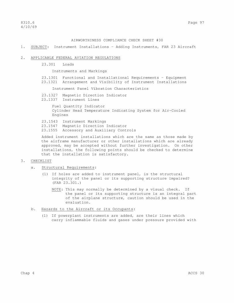
8310.6 Page 97 4/10/69
AIRWORTHINESS COMPLIANCE CHECK SHEET #30
1. SUBJECT : Instrument Installations – Adding Instruments, FAR 23 Aircraft
2. APPLICABLE FEDERAL AVIATION REGULATIONS
23.301 Loads
Instruments and Markings
23.1301 Functional and Installational Requirements – Equipment 23.1321 Arrangement and Visibility of Instrument Installations
Instrument Panel Vibration Characteristics
23.1327 Magnetic Direction Indicator 23.1337 Instrument Lines
Fuel Quantity Indicator Cylinder Head Temperature Indicating System for Air-Cooled Engines
23.1543 Instrument Markings 23.1547 Magnetic Direction Indicator 23.1555 Accessory and Auxiliary Controls
Added instrument installations which are the same as those made by the airframe manufacturer or other installations which are already approved, may be accepted without further investigation. On other installations, the following points should be checked to determine that the installation is satisfactory.
3. CHECKLIST
a. Structural Requirements :
(1) If holes are added to instrument panel, is the structural integrity of the panel or its supporting structure impaired? (FAR 23.301.)
NOTE: This may normally be determined by a visual check. If the panel or its supporting structure is an integral part of the airplane structure, caution should be used in the evaluation.
b. Hazards to the Aircraft or its Occupants :
(1) If powerplant instruments are added, are their lines which carry inflammable fluids and gases under pressure provided with
Chap 4 ACCS 30

Page 98 8310.6 4/10/69
Restricted orifices or other safety devices at the source of pressure to prevent excessive escape of fluid or gas in case of line failure? (FAR 23.1337.)
c. Operating Aspects :
(1) Are added flight, navigation and powerplant instruments in- stalled in such a manner that they are easily visible for use by the pilot? (FAR 23.1321.)
(2) Are added identical powerplant instruments on multiengine aircraft so located as to prevent any confusion as to the engines to which they relate? (FAR 23.1321.)
(3) Is the added magnetic compass installed in the aircraft so that its accuracy is not affected excessively by vibration and transient magnetic fields? (FAR 23.1327.)
(4) Is the added magnetic compass compensated for deviation error not exceeding plus or minus 10 degrees on any heading in level flight? (FAR 23.1327.)
(5) If a magnetic compass is added, is a placard installed with the compass deviation error recorded? (FAR 23.1327, and FAR 23.1547.)
d. Detail Design Standards :
(1) Are the instrument panel vibration characteristics such as not to impair the accuracy of added instruments? (FAR 23.1321.)
(2) Are the applicable instrument connector tubings, flexible lines, electrical conductors, and cables to the added instru- ments, considered satisfactory to perform their intended function and are their installations satisfactory? (FARs 23.1301, 23.1321, and 23.1337.)
(3) Are instruments properly range marked or placarded? (FAR 23.1543, and FAR 23.1583.)
ACCS 30 Chap 4

8310.6 Page 99 4/10/69
AIRWORTHINESS COMPLIANCE CHECK SHEET #31
1. SUBJECT : Instrument Installations – Relocating Instruments, FAR 25 Aircraft
2. APPLICABLE FEDERAL AVIATION REGULATIONS :
25.301 Loads 25.1301 Functional and Installational Requirements - Equipment 25.1309 Equipment, Systems, and Installations 25.1321 Arrangement and Visibility of Instrument Installations 25.1323 Flight and Navigation Instruments 25.1325 Flight and Navigation Instruments 25.1327 Flight and Navigation Instruments 25.1329 Flight and Navigation Instruments 25.1331 Flight and Navigation Instruments 25.1337 Powerplant Instruments 25.1433 Vacuum Systems 25.1541 Markings and Placards 25.1543 Instrument Markings 25.1545 Air Speed Indicator 25.1547 Magnetic Direction Indicator 25.1549 Powerplant Instruments 25.1551 Oil Quantity Indicator 25.1553 Fuel Quantity Indicator
Relocated instrument installations which are the same as those made by the airframe manufacturer or other installations which are already approved, may be accepted without further investigation. On other installations, the following points should be checked to determine that the installation is satisfactory.
3. CHECKLIST :
a. Structural Requirements :
(1) If holes are added to the instrument panel, is the structural integrity of the panel or its supporting structure impaired? (FAR 25.301)
NOTE: This may normally be determined by a visual check. If the panel or its supporting structure is an integral part of the airplane structure, caution should be used in the evaluation.
b. Hazards to the Aircraft or its Occupants :
(1) If powerplant instruments are relocated, are their lines which carry inflammable fluids and gases under pressure provided with restricted orifices or other safety devices at the source of
Chap 4 ACCS 31
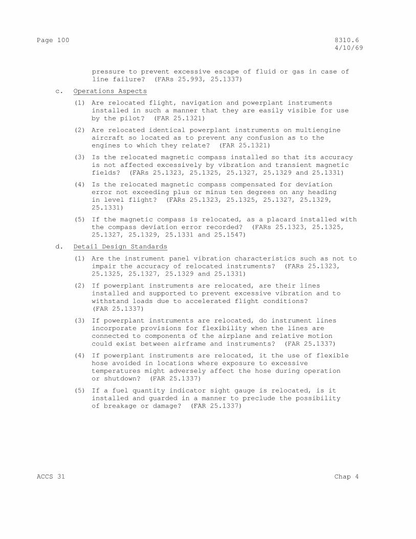
Page 100 8310.6 4/10/69
pressure to prevent excessive escape of fluid or gas in case of line failure? (FARs 25.993, 25.1337)
c. Operations Aspects
(1) Are relocated flight, navigation and powerplant instruments installed in such a manner that they are easily visible for use by the pilot? (FAR 25.1321)
(2) Are relocated identical powerplant instruments on multiengine aircraft so located as to prevent any confusion as to the engines to which they relate? (FAR 25.1321)
(3) Is the relocated magnetic compass installed so that its accuracy is not affected excessively by vibration and transient magnetic fields? (FARs 25.1323, 25.1325, 25.1327, 25.1329 and 25.1331)
(4) Is the relocated magnetic compass compensated for deviation error not exceeding plus or minus ten degrees on any heading in level flight? (FARs 25.1323, 25.1325, 25.1327, 25.1329, 25.1331)
(5) If the magnetic compass is relocated, as a placard installed with the compass deviation error recorded? (FARs 25.1323, 25.1325, 25.1327, 25.1329, 25.1331 and 25.1547)
d. Detail Design Standards
(1) Are the instrument panel vibration characteristics such as not to impair the accuracy of relocated instruments? (FARs 25.1323, 25.1325, 25.1327, 25.1329 and 25.1331)
(2) If powerplant instruments are relocated, are their lines installed and supported to prevent excessive vibration and to withstand loads due to accelerated flight conditions? (FAR 25.1337)
(3) If powerplant instruments are relocated, do instrument lines incorporate provisions for flexibility when the lines are connected to components of the airplane and relative motion could exist between airframe and instruments? (FAR 25.1337)
(4) If powerplant instruments are relocated, it the use of flexible hose avoided in locations where exposure to excessive temperatures might adversely affect the hose during operation or shutdown? (FAR 25.1337)
(5) If a fuel quantity indicator sight gauge is relocated, is it installed and guarded in a manner to preclude the possibility of breakage or damage? (FAR 25.1337)
ACCS 31 Chap 4

8310.6 Page 101 (and 102) 4/10/69
(6) If a relocated fuel sight gauge forms a trap in which water can collect and freeze, is a means provided to permit drainage on the ground? (FAR 25.1337)
(7) Are the applicable instrument connector tubings, flexible lines, electrical conductors, and cables to relocated instruments considered satisfactory to perform their intended function and are their installations satisfactory? (FARs 25.993, 25.1309, 25.1323, 25.1325, 25.1327, 25.1329, 25.1331 and 25.1337)
Chap 4 ACCS 31

8310.6 Page 103 4/10/69
AIRWORTHINESS COMPLIANCE CHECK SHEET #32
1. SUBJECT : Instrument Installations – Adding Instrument, FAR 25 Aircraft
2. APPLICABLE FEDERAL AVIATION REGULATIONS
25.301 Loads 25.1301 Functional and Installation Requirements – Equipment 25.1309 Equipment, Systems, and Installations 25.1321 Arrangement and Visibility of Instrument Installations 25.1323 Flight and Navigation Instruments 25.1325 Flight and Navigation Instruments 25.1327 Flight and Navigation Instruments 25.1329 Flight and Navigation Instruments 25.1331 Flight and Navigation Instruments 25.1337 Powerplant Instruments 25.1433 Vacuum Systems 25.1541 Markings and Placards 25.1543 Instrument Markings 25.1545 Air Speed Indicator 25.1547 Magnetic Direction Indicator 25.1549 Powerplant Instruments 25.1551 Oil Quantity Indicator 25.1553 Fuel Quantity Indicator
3. CHECKLIST
a. Structural Requirements :
(1) If holes are added to instrument panel, is the structural integrity of the panel or its supporting structure impaired? (FAR 25.301.)
NOTE: This may normally be determined by a visual check. If the panel or its supporting structure is an integral part of the airplane structure, caution should be used in the evaluation.
b. Hazards to the Aircraft or its Occupants :
(1) If powerplant instruments are added, are their lines which carry inflammable fluids and gases under pressure provided with restricted orifices or other safety devices at the source of pressure to prevent excessive escape of fluid or gas in case of line failure? (FARs 25.993, and 25.1337.)
c. Operating Aspects :
(1) Are added flight, navigation and powerplant instruments installed
Chap 4 ACCS 32
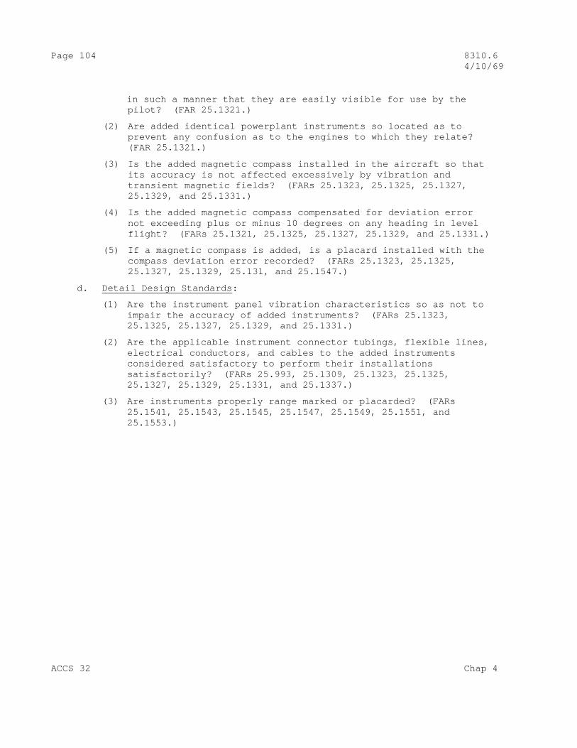
Page 104 8310.6 4/10/69
in such a manner that they are easily visible for use by the pilot? (FAR 25.1321.)
(2) Are added identical powerplant instruments so located as to prevent any confusion as to the engines to which they relate? (FAR 25.1321.)
(3) Is the added magnetic compass installed in the aircraft so that its accuracy is not affected excessively by vibration and transient magnetic fields? (FARs 25.1323, 25.1325, 25.1327, 25.1329, and 25.1331.)
(4) Is the added magnetic compass compensated for deviation error not exceeding plus or minus 10 degrees on any heading in level flight? (FARs 25.1321, 25.1325, 25.1327, 25.1329, and 25.1331.)
(5) If a magnetic compass is added, is a placard installed with the compass deviation error recorded? (FARs 25.1323, 25.1325, 25.1327, 25.1329, 25.131, and 25.1547.)
d. Detail Design Standards :
(1) Are the instrument panel vibration characteristics so as not to impair the accuracy of added instruments? (FARs 25.1323, 25.1325, 25.1327, 25.1329, and 25.1331.)
(2) Are the applicable instrument connector tubings, flexible lines, electrical conductors, and cables to the added instruments considered satisfactory to perform their installations satisfactorily? (FARs 25.993, 25.1309, 25.1323, 25.1325, 25.1327, 25.1329, 25.1331, and 25.1337.)
(3) Are instruments properly range marked or placarded? (FARs 25.1541, 25.1543, 25.1545, 25.1547, 25.1549, 25.1551, and 25.1553.)
ACCS 32 Chap 4
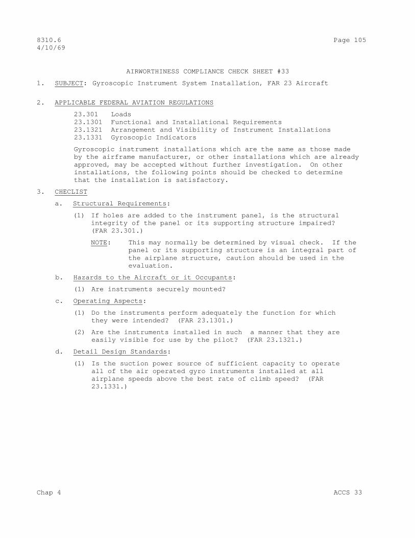
8310.6 Page 105 4/10/69
AIRWORTHINESS COMPLIANCE CHECK SHEET #33
1. SUBJECT : Gyroscopic Instrument System Installation, FAR 23 Aircraft
2. APPLICABLE FEDERAL AVIATION REGULATIONS
23.301 Loads 23.1301 Functional and Installational Requirements 23.1321 Arrangement and Visibility of Instrument Installations 23.1331 Gyroscopic Indicators
Gyroscopic instrument installations which are the same as those made by the airframe manufacturer, or other installations which are already approved, may be accepted without further investigation. On other installations, the following points should be checked to determine that the installation is satisfactory.
3. CHECLIST
a. Structural Requirements :
(1) If holes are added to the instrument panel, is the structural integrity of the panel or its supporting structure impaired? (FAR 23.301.)
NOTE: This may normally be determined by visual check. If the panel or its supporting structure is an integral part of the airplane structure, caution should be used in the evaluation.
b. Hazards to the Aircraft or it Occupants :
(1) Are instruments securely mounted?
c. Operating Aspects :
(1) Do the instruments perform adequately the function for which they were intended? (FAR 23.1301.)
(2) Are the instruments installed in such a manner that they are easily visible for use by the pilot? (FAR 23.1321.)
d. Detail Design Standards :
(1) Is the suction power source of sufficient capacity to operate all of the air operated gyro instruments installed at all airplane speeds above the best rate of climb speed? (FAR 23.1331.)
Chap 4 ACCS 33

Page 106 8310.6 4/10/69
(2) Is an indicating means provided which will indicate that the instruments are receiving adequate suction for their required performance? (FAR 23.1331.)
(3) If the airplane is multiengine, does the suction air system provide satisfactory protection, in case of line breakage or leakage to an instrument, so as not to impair the performance of the other instruments? (FAR 23.1331.)
(4) Is the electrical power supply of adequate capacity to operate all of the electrically operated gyro instruments installed? (FAR 23.1331.)
(5) Does the power failure warning indication provide adequate warning to indicate when proper power is not being received by the instruments? (FAR 25.1331.)
(6) If the airplane is multiengine, are two completely independent power sources provided which are actuated by separate means? (FAR 23.1331.)
(7) If the airplane is multiengine, is the power source circuitry such as not to impair the operation of the instruments should breakage of an electrical conductor to an instrument occur? (FAR 23.1331.)
(8) If the airplane is multiengine, is a positive means provided for selecting either power source? (FAR 23.1331.)
(9) If the airplane is multiengine, is a means provided for indication the power source output? (FAR 23.133.)
(10) Are the gyroscopic instruments and their systems installed to preclude malfunctioning due to rain, oil, and other detrimental elements? (FAR 23.1331.)
(11) If an engine-driven suction are pump(s) is installed, is it compatible with the engine mounting pad and drive provided for such pumps? (FAR 23.1301.)
(12) If an engine-driven suction air pump(s) is installed, are flexible type pump connector lines provided? (FAR 23.1301.
(13) Are the shock absorbing characteristics of the instrument panel satisfactory after adding equipment? (FAR 23.1321.)
ACCS 33 Chap4
8310.6 Page 107 4/10/69
AIRWORTHINESS COMPLICANE CHECK SHEET #34
1. SUBJECT : Gyroscopic Instrument System Installations, FAR 25
2. APPLICABLE FEDERAL AVIATION REGULATIONS
25.301 Loads 25.1163 Powerplant Accessories 25.1303 Flight and Navigational Instruments 25.1321 Arrangement and Visibility of Instrument Installations 25.1331 Functional and Installational Requirements 25.1433 Vacuum Systems
Gyroscopic instrument installations which are the same as those made by the airframe manufacturer, or other installations which are already approved, may be accepted without further investigation. On other installations, the following points should be checked to determine that the installation is satisfactory:
3. CHECKLIST
a. Structural Requirements :
(1) If holes are added to the instrument panel, is the structural integrity of the panel or its supporting structure impaired? (FAR 25.301)
This may normally be determined by a visual check. If the panel or its supporting structure is an integral part of the airplane structure, caution should be used in the evaluation.
b. Hazards to the Aircraft or its Occupants :
None
c. Operating Aspects :
(1) Do the instruments perform adequately the function for which they were intended? (FAR 25.1303)
(2) Are the instruments installed in such a manner that they are readily visible for use by the pilot? (FAR 25.1321)
d. Detail Design Standards :
(1) Is the power source of sufficient capacity to operate all of the air operated gyro instruments installed adequately during flight? (FAR 25.1331)
Chap 4 ACCS 34

Page 108 8310.6 4/10/69
(2) Is an indicating means provided which will indicate that the instruments are receiving adequate suction for their required performance? (FAR 25.1331)
(3) If the airplane is multiengine, does the suction air system provide satisfactory protection, in case of line breakage or leakage to an instrument, so as not to impair the performance of the other instruments? (FAR 25.1331.)
(4) Is the power supply of adequate capacity to operate all of the electrically operated gyro instruments installed? (FAR 25.1331.)
(5) Does the power failure warning indication provide adequate warning to indicate when proper power is not being received by the instruments? (FAR 25.1331.)
(6) Is the power source circuity such as not to impair the operation of the instruments should breakage of an electrical conductor to an instrument occur? (FAR 25.1331.)
(7) If the airplane is multiengine, are two completely independent power sources provided which are actuated by separate means? (FAR 25.1331.)
(8) Is a positive means provided for selecting either power source? (FAR 1331.)
(9) Is a means provided for indicating the power source outputs? (FAR 25.1331.)
(10) Are the gyroscopic instruments and their systems installed to preclude malfunctioning due to rain, oil, and other detrimental elements? (FAR 25.1331.)
(11) If an engine-driven suction air pump(s) is installed, is it compatible with the engine mounting pad and drive provided for such pumps? (FAR 25.1163.)
(12) If an engine-driven suction air pump(s) is installed, are fire resistant flexible type pump connector lines provided? (FAR 25.1433.)
(13) If an engine-driven suction air pump(s) is installed, is a means provided to automatically relieve unsafe air temperatures on the exhaust (high pressure) port side of the pump? (FAR 25.1433.)
ACCS 34 Chap 4

8310.6 Page 109 4/10/69
(14) If engine oil is used as a lubricant and seal in a suction airpump, is the exhaust (high pressure) port outlet connected directly to an air/oil separator with a fire resistant line? (FAR 25.1433.)
Chap 4 ACCS 34
8310.6 CHG 1 Page 111 10/21/71
AIRWORTHINESS COMPLIANCE CHECK SHEET #35
1. SUBJECT : Installation of Liquid Nitrogen Air Conditioners.
2. APPLICABE REGULATIONS .
a. Federal Aviation Regulations, Part 23
21.1(b) Applicability 21.16 Special conditions 21.21 Issue of T.C.; normal, utility, etc. 21.303 Replacement or modifications parts 21.305 Approval of materials, parts, processes, etc. 23.21 Proof of compliance 23.23 Local distribution limits 23.301 Loads 23.303 Factor of safety 23.305 Strength and deformation 23.307 Proof of structure 23.561 Emergency landing conditions 23.603 Materials and workmanship 23.605 Fabrication methods 23.609 Protection of structure 23.611 Accessibility 23.613 Material strength properties & design values 23.777 Cockpit controls 23.787 Cargo compartments 23.1357 Circuit protective devices 23.1365 Electric cables 23.1367 Switches 23.1519 Weight & center of gravity 23.1541 General (marking & placards) 23.1555 Control markings 23.1581 Airplane Flight Manual (General) 23.1589 Loading information 43.13 Performance rules (General)
b. Civil Aeronautics Manual, Part 3
3.0 Applicability 3.18 Approval of materials, parts, processes, and appliances 3.71 Weight & balance 3.76 Center of gravity position 3.171 Loads 3.172 Factor of safety 3.173 Strength and deformations 3.174 Proof of structure 3.292 Materials and workmanship
Chap 4 ACCS 35
Page 112 8310.6 CHG 1 10/21/71
3.293 Fabrication methods 3.295 Protection 3.296 Inspection provisions 3.301 Material strength properties and design values 3.384(a) Cockpit controls 3.392 Cargo compartments 3.690 Fuses or circuit breakers 3.693 Electric cables 3.694 Switches 3.748 Airplane weight 3.755 Markings & placards 3.762 General - control markings 3.777 Airplane flight manual
c. Referenced Federal Regulations Other Than Federal Aviation Regulations
CFR Title 49 – Transportation, Chapter 1.
173.304(b) (2) Relief valve setting 178.57-20 LN 2 pressure vessel markings
(1) This ACCS has been developed with assumptions that the Liquid Nitrogen Air-Conditioning System would be permanent. However, it is not intended that any part of the checklist be deleted for so-called portable or temporary installations.
(2) In general, systems installations which are the same as those made by the airframe manufacturer, or other installations which are already approved may be accepted without a detail investigation so long as the inspector satisfies himself that the system is the same.
(3) On other installations , the following checklist is designed to guide the inspector to the criteria deemed necessary for the inspector to approve the system installation.
3. CHECKLIST
a. Structural Requirements
(1) Is the liquid nitrogen supply pressure vessel (the most common one in use is a Dewar, which is defined as a double walled vacuum bottle) located in a suitable location that places it as close as practical to the evaporator unit? (FAR 23.609, .611), (3.295)
ACCS 35 Chap 4

8310.6 CHG 1 Page 113 10/21/71
(2) Is the supply pressure vessel and evaporator unit mounted securely to a frame member or other structure so as to with- stand the required inertial force levels? (FAR 23.301, .303, .307, .603, .605), 3.171, 3.18, 3.174, 3.292, 3.293). This determination may be made by direct comparison with an exist- ing approved modification which has the same or similar weight, size, and design, or by structural analysis or static test.
(3) Are the lines connecting the supply pressure vessel and the evaporator unit free of sharp or usual bends or obstructions? (FAR 23.603, .605), (3.292, .293)
(4) Are there adequate procedures taken to insure the integrity of the structure if installed in a pressurized aircraft? (FAR 23.303, .305, .603, .605, .607, .609), (3.18, 3.292, 3.293, 3.295). It is suggested that the inspector check with the controlling T.C. region for special considerations and supplementary special design conditions when he is in doubt due to some unusual aspect of the aircraft.
b. Hazards to the Aircraft or Occupants . Perhaps the greatest hazard involved in an LN 2 system is the possibility of cold-liquid burns or the discharge of sufficient quantities of LN 2 into poorly ventilated occupied areas as to reduce the oxygen content to dangerously low levels. The approving inspector should keep this in mind when inspecting LN 2 installations. It is important that all components and plumbing be suitable for the handling of LN 2.
(1) Does the LN 2 supply pressure vessel or vessels have the proper markings? (Note: There are two acceptable markings. Federal Regulations Title 49 – Transportation Specification 4L or American Society of Mechanical Engineers Boiler and Pressure Vessel Code Standard for Unfired Pressure Vessels.)
(a) 4L Specification pressure vessels will be marked DOT-4L followed by a number which indicates the design service pressure, i.e., DOT-4L200. This bottle could be operated at working pressures up to 200 PSI.
(b) Pressure vessels manufactured to A.S.M.E. standards will be marked with a U or UM symbol stamped inside a shield.
(c) The markings shall be stamped plainly and permanently on shoulder or top head of jacket or on a permanently attached plate or head protective ring.
Chap 4 ACCS 35
Page 114 8310.6 CHG 1 10/21/71
(d) In the event the pressure vessels are not marked as above the inspector should require proof that the components meet the requirements of FAR 43.13. (Reference AC 20-62A, paragraph 5 and 6)
(2) Are the valves, lines, fittings, and/or other hardware capable of withstanding the maximum pressures and flows the systems may be subjected to? (i.e. cylinders must be limited by a pressure control valve so sized and set that the pressure can never exceed 15 PSI lower than one and one fourth (1 ¼) times the marked service pressure. (Ref. Code of Federal Regulations, Title 49-Transportation, Section 173.304(b) (2). The working pressure of the LN2 system is likely to be con- siderably below the service pressure markings on the bottle. The service pressure is the pressure up to which the vessel is considered safe to operate while the working pressure is that which the particular system may be expected to reach in normal operations.
(3) Are the vent lines and the supply pressure vessel protected from the possibility of damage to the system by cargo or baggage placement or loading operation? (FAR 23.609, .787), (3.295, 3.292)
(4) Are the vent lines, pressure vessel lines, etc., located and supported properly in case of a crash landing giving due consideration to occupants survival? (FAR 23.561, .603, .605, .613, .787), (3.292, .293, .301, .392)
(5) Are the vent and burst tube discharge ends located where the escaping gas will not directly enter any cabin air or critical system intakes? (FAR 23.561, .603, .605, .613, .787) (3.292, .293, .301, 3.92)
(6) Are personnel protected form contact with the lines, liquid or gaseous nitrogen? (FAR 23.561)
(7) Are the evaporator moisture collecting pan-drain tube, burst disc-escape tube, and exhaust tube vented outside the aircraft without sharp tube bends what will restrict free flow? (FAR 23.603, .605, .609, (3.292, .293, .295)
(8) Are the ends of drain and vent lines accessible so they may be inspected and/or cleaned of obstructions and are they in a nonpositive pressure area so that adequate gas escape is possible? (FAR 23.603, .609), (3.292, .293, 295)
(9) Has the weight-and-balance effect including weight limitations been considered? Have appropriate placards and manuals been change if necessary? (FAR 23.21, .23, .1589), (3.171, .748)
Chap 4 ACCS 35

8310.6 CHG 1 Page 115 10/21/71
c. Operating Aspects .
(2) Is a gauge provided to show the pressure in the supply vessel? (FAR 23.1541), (3.755)
(3) Are the system controls readily accessible to the crew? (FAR 23.1367, (3.695)
(4) Is there a vent to discharge the LN 2 overboard after the refrigeration is spent and to route excess overboard during refilling operations? (FAR 23.609), (3.295)
(5) Are controls properly placarded and visible and is the operating information available? (FAR 23.611, .1555, .1581), (3.755, 3.777)
d. Detail Design Standards .
An important design consideration that must be considered in the design and installation of any cryogenic system is the hazard associated with line or tank rupture whenever liquified gas is trapped. Pressures can theoretically reach extremely high values if provisions are not made to furnish adequate relief. These provisions should take into account the possibility that relief, automatic or manual, valves may malfunction to trap LN 2
(1) Are at least two methods of relieving excessive pressure in the cryogenic system provided? (FAR 23.603, .605, .609), (3.292, .293, .295). These must consist of at least one pressure relief valve that may be adjustable and a burst disc with a fixed rupture pressure.
(2) Is the pressure relief valve set at a value not to exceed 15 PSI lower than one and one-fourth ( 1 ¼ ) time the pressure vessel marked service pressure? (FAR 23.609, .613, .1555, .1581), (3.295, .301, .755, .777) (Code of Federal Regulations Title 49 – Transportation, 1, 173, .304(b) (2).)
(3) Is the burst disc rupture value not in excess of 150% of the working pressure of the pressure vessel. (FAR 23.603, .605, .609, .613), (3.292, .293, .295, .301)
(4) Are the pressure relief valve and vent valve vented over- board? Is the burst disc vented overboard so that in event it should burst the cryogenic fluid will not strike personnel, damage essential equipment, structure, or deplete the oxygen level in the passenger compartment to dangerous levels. (FAR 23.609), (3.295)
Chap 4 ACCS 35

Page 116 8310.6 CHG 1 10/21/71
NOTE: Safety precaution guides of commercial companies handling LN2 state that the oxygen level should not fall below 16% in spaces occupied by personnel. It would be difficult to make such a determination but the inspector should keep in mind that the expansion coefficient of LN 2 is approximately 696 to 1 at 72 °F. Therefore, if a full supply vessel dis- charged rapidly into a passenger cabin area, it is possible dangerous oxygen levels could result.
(5) Are the supply pressure vessel lines, relief valve and burst disc designed to operate at cryogenic temperatures at the pressure setting of the burst disc? (FAR 23.603, .605, .609, .613), (3.292, .293, .295, .301)
This may be determined by direct comparison with an existing approved installation which has the same or similar design. Material markings are specified in other section of this ACCS. In the event direct comparison cannot be made the inspector should require proof that the systems valves and plumbing will withstand the pressure and temperatures involved.
(6) Is the electric power supply properly connected to the fan and not overloading the electrical system when operating? (FAR 23.1357, .1351), (3.690, .693, .694)
(7) Is the system installed so as to permit inspection without removal of other unrelated equipment? (FAR 23.611)
ACCS 35