handbook for apollo instrumentation ships - nasa · the handbook for apollo instrumentation ships,...
TRANSCRIPT
HANDBOOK
FOR
MG-402
APOLLO INSTRUMENTATION
SHIPS
September 1, 1968
This publication supersedes MG-402 dated September 30, 1966.
Prepared for
NATIONAL AERONAUTICS AND SPACE ADMINISTRATION
Contract NAS5-10750
MG-402 Table of Contents
TABLE OF CONTENTS Section I. GENERAL DESCRIPTION
Paragraph
Introduction . . . . . . . . . . . . . . . . . . . . . . . . . . . . . . . . . . . . . . . . . . . . . . . . . . . Purpose of Handbook . . . . . . . . . . . . . . . . . . . . . . . . . . . . . . . . . . . . . . . . .
Ships' Purpose . . . . . . . . . . . . . . . . . . . . . . . . . . . . . . . . . . . . . . . . . . . . . . .
1 9-Class . . . . . . . . . . . . . . . . . . . . . . . . . . . . . . . . . . . . . . . . . . . . . . . . . .
6-Class . . . . . . . . . . . . . . . . . . . . . . . . . . . . . . . . . . . . . . . . . . . . . . . . . . .
Ships' Personnel . ' . . . . . . . . . . . . . . . . . . . . . . . . . . . . . . . . . . . . . . . . . . . . . .
Reporting Aboard . . . . .. . . . . . . . . . . . . . . . . . . . . . . . . . . . . . . . . . . . . . . . .
1 9-Class . . . . . . . . . . . . . . . . . . . . . . . . . . . . . . . . . . . . . . . . . . . . . . . . . . . . .
6-Class . . . . . . . . . . . . . . . . . . . . . . . . . . . . . . . . . . . . . . . . . . . . . . . . . . . . . .
Ship's Support Plans . . . . . . . . . . . . . . . . . . . . . . . . . . . . . . . . . . . . . . . . . . . . System Tests . . . . . . . . . . . . . . . . . . . . . . . . . . . . . . . . . . . . . . . . . . . . . . . . . . .
Target AcqUIsitlon . . . . . . . . . . . . . . . . . . . . . . . . . . . . . . . . . . . . . . . . . . . . . .
Post-Mission Operations . . . . . . . . . . . . . . . . . . . . . . . . . . . . . . . . . . . . . . . . .
Ships' Performance Parameters . . . . . . . . . . . . . . . . . . . . . . . . . . . . . . . . . . . 1 9-Class . . . . . . . . . . . . . . . . . . . . . . . . . . . . . . . . . . . . . . . . . . . . . . . . . . . . .
6-Class . . . . . . . . . . . . . . . . . . . . . . . . . . . . . . . . . . . . . . . . . . . . . . . . . . . . . .
Bridge . . . . . . . . . . . . . . . . . . . . . . . . . . . . . . . . . . . . . . . . . . . . . . . . . . . . . .
Engine Room . . . . . . . . . . . . . . . . . . . . . . . . . . . . . . . . . . . . . . . . . . . . . . . .
Instrumentation Machine Shop . . . . . . . . . . . . . . . . . . . . . . . . . . . . . . . . .
Power Generation . . . . . . . . . . . . . . . . . . . . . . . . . . . . . . . . . . . . . . . . . . . .
Duration of Cruise . . . . . . . . . . . . . . . . . . . . . . . . . . . . . . . . . . . . . . . . . . .
PosItIonIng . . . . . . . . . . . . . . . . . . . . . . . . . . . . . . . . . . . . . . . . . . . . . . . . . .
Ship's Communications . . . . . . . . . . . . . . . . . . . . . . . . . . . . . . . . . . . . . . . .
Ships' Layout . . . . . . . . . . . . . . . . . . . . . . . . . . . . . . . . . . . . . . . . . . . . . . . . . .
1 9-Class . . . . . . . . . . . . . . . . . . . . . . . . . . . . . . . . . . . . . . . . . . . . . . . . . . . . .
6-Class . . . . . . . . . : . . . . . . . . . . . . . . . . . . . . . . . . . . . . . . . . . . . . . . . . . . . .
Internal Telephone System . . . . . . . . . . . . . . . . . . . . . . . . . . . . . . . . . . . . . . .
P ABX Instructions . . . . . . . . . . . . . . . . . . . . . . . . . . . . . . . . . . . . . . . . . . . Living Quarters . . . . . . . . . . . . . . . . . . . . . . . . . . . . . . . . . . . . . . . . . . . ' . . . . . .
Staterooms . . . . . . . . . . . . . . . . . . . . . . . . . . . . . . . . . . . . . . . . . . . . . . . . . .
Technicians' Lounge . . . . . . . . . . . . . . . . . . . . . . . . . . . . . . . . . . . . . . . . . .
Technicians' Messroom . , . . . . . . . . . . . . . . . . . . . . . . . . . . . . . . . . . . . . . .
Ship's Store . . . . . . . . . . . . . . . . . . . . . . . . . . . . . . . . . . . . . . . . . . . . . . . . . .
Physical Training Room . . , . . . . . . . . . . . . . . . . . . . . . . . . . . . . . . . . . . . .
Technicians' Laundry . . . . . . . . . . . . . . . . . . . . . . . . . . . . . . . . . . . . . . . . .
Barber Shop . . . . . . . . . . . . . . . . . . . . . . . . . . . . . . . . . . . . . . . . . . . . . . . . .
Medical Facilities . . . . . . . . . . . . . . . . . . . . . . . . . . . . . . . . . . . . . . . . . . . . .
Technical Library . . . . . . . . . . . . . . . . . . . . . . . . . . . . . . . . . . . . . . . . . . . .
Entertainment . . . . . . . . . . . . . . . . . . . . . . . . . . . . . . . . . . . . . . . . . . . . . . .
Page
1-1 1- 1 1- 1 1 - 1 1 -2 1 -2 1 -2 1 -2 1 -2 1 -2 1 -3 1 -3 1 -3 1 -4 1 -4 1 -4 1 -6 1-6 1 -6 1 -6
1 - 1 0 1 - 1 0 1-1 0 1 - 1 0 1 - 1 0 1 - 1 3 1 -26 1 -26 1 -27 1 -27 1-27 1 -27 1 -27 1-27 1 -27 1 -27 1 -27 1 -27 1-27
i
Table of Contents MG-402
TABLE OF CONTENTS (CONT.) Paragraph Page
11
Lifesaving Equipment (19-Class) 0 0 0 0 0 0 0 0 0 0 0 0 0 0 0 0 0 0 0 0 0 0 0 0 0 0 0 0 0 0 0 0 0 1-32 Lifesaving Equipment (6-Class) 0 0 0 0 0 0 0 0 0 0 0 0 0 0 0 0 0 0 0 0 0 0 0 0 0 0 0 0 0 0 0 0 0 0 1-32 Personal Gear 0 0 0 0 0 0 0 0 0 0 0 0 0 0 0 0 0 0 0 0 0 0 0 . 0 0 0 0 0 0 0 0 0 0 0 0 0 0 0 0 0 0 0 0 0 0 0 0 0 0 1-32 Regulations 0 0 0 0 0 0 0 0 0 0 0 0 0 0 0 0 0 0 0 0 0 0 0 0 0 0 0 0 0 0 0 0 0 0 0 0 0 0 0 0 0 0 0 0 0 0 0 0 0 0 0 0 1-32 Sailing Notice 0 0 0 0 • 0 0 0 0 0 0 0 0 0 0 0 0 0 0 0 0 0 0 0 0 0 0 0 0 0 0 0 0 0 0 0 0 0 0 0 0 0 0 0 0 0 0 0 0 0 1-32 Mail 0 0 0 0 0 0 0 0 0 0 • 0 0 0 • 0 • 0 0 0 0 0 0 0 0 0 0 0 0 0 0 0 0 0 0 0 0 0 0 0 0 0 0 0 0 0 0 0 0 0 0 0 0 0 0 0 0 1-33/1-34
SAFETY
Ships' Safety Precautions o . 0 0 0 0 0 0 0 0 0 0 0 0 0 0 0 0 0 0 0 0 0 0 0 0 0 0 0 0 0 0 0 0 0 0 0 0 0 0 S-1 Station Bill 0 0 0 0 0 0 0 0 0 0 0 0 0 • 0 0 0 0 0 0 • 0 0 0 0 0 0 0 0 0 0 0 0 0 0 0 0 0 0 0 0 0 0 0 • 0 0 0 0 0 0 0 S-1 Abandon Ship o . 0 0 • 0 • • 0 • 0 0 0 0 0 0 • • • 0 0 0 • 0 0 0 0 0 0 0 0 • 0 0 0 0 0 0 0 0 0 0 0 0 0 0 0 0 0 S-1 Fire 0 0 0 0 0 0 0 0 0 • • • 0 0 • 0 0 0 0 • • • 0 • 0 0 0 • 0 0 0 0 0 0 0 • 0 0 0 0 0 0 0 0 0 . 0 0 0 0 0 0 0 0 0 0 0 0 S-2 Emergency Traffic Flow 0 0 0 0 0 0 . 0 • • • • 0 0 0 0 0 0 0 . 0 0 0 0 0 0 0 0 0 0 0 0 0 0 0 0 0 0 0 0 0 S-2 Refueling . . ... .. . . .. . . . . 0 • • • • • • • • 0 • • • • • • • • • • • • • • • • • • • • • • • • 0 0 0 0 S-2 Restricted Areas . . . . 0 0 o • • • 0 0 0 • 0 • • 0 0 0 0 0 0 0 0 0 0 0 0 0 0 0 0 0 0 0 0 0 0 0 0 0 0 0 0 0 0 0 S-2 Water Conservation . . . 0 0 0 . 0 . 0 0 ' 0 0 • 0 0 0 0 0 0 0 0 0 0 0 0 0 0 0 0 0 0 0 0 0 0 0 0 0 0 0 0 0 0 S-2 RF-Radiation Hazard Warning 0 • 0 0 • • 0 • 0 0 0 0 0 0 • • 0 0 0 0 0 0 0 0 0 0 0 0 0 0 0 0 0 0 0 S-2
Section II. SHIPS' OPERATION
General o . 0 • 0 0 0 0 0 0 0 0 0 • 0 0 0 0 0 0 • • • • 0 0 0 0 0 0 0 0 0 0 0 0 0 0 • 0 0 0 0 • 0 0 0 0 0 0 0 0 0 • 0 2-1 Tracking Radar System o • • 0 • 0 0 0 0 0 0 0 0 . 0 • 0 0 • • 0 0 0 0 0 0 0 0 0 0 0 0 0 0 0 0 0 0 0 0 0 0 2-5
ADRAM 0 0 0 0 0 0 0 0 0 0 0 0 . 0 0 . 0 • • • o . 0 0 0 0 0 0 0 • • 0 0 0 0 0 o . 0 0 0 0 o . 0 0 o . 0 0 0 0 2-8 AUXTRACK 0 0 0 • 0 • 0 • 0 0 • • • • 0 0 0 0 • 0 • 0 • 0 0 0 0 0 0 0 • 0 0 0 0 0 0 0 0 0 0 0 0 0 0 0 0 2-8
Unified S-Band System . 0 0 • 0 0 • 0 0 0 • 0 0 0 0 0 0 • 0 0 0 0 0 0 0 0 0 0 0 0 0 0 0 0 0 0 0 0 0 0 0 0 2-11 Central Data Processing System 0 0 • 0 • 0 0 0 0 0 • • • 0 • 0 0 0 • 0 0 0 0 0 0 0 0 0 0 0 0 0 0 0 • 2-17
CDP Functions. 0 0 • 0 0 0 0 0 . 0 0 0 • 0 0 ' 0 0 0 0 0 0 0 0 0 0 0 0 0 0 0 0 0 0 0 0 0 0 0 0 0 0 0 . 0 0 2-21 Mission Support 0 0 0 0 • • • 0 • • o . 0 0 0 0 0 0 • 0 0 0 0 0 0 0 0 0 0 0 • • • 0 • • • • • • 0 • • 0 2-21 Station Support . .. .. .. . . . 0 • • • • • • • • • • • 0 0 , • • • • • • 0 • • • • • • 0 • • • • • 2-23
Telemetry System . .. . . .. . . . . . .. . . . .. .. . . . .. 0 0 • • • • • • • • • • • • • • 0 • 0 0 • 2-25 Command Control System (19-Class Only) ........................ 2-31 Timing System . . . .... . . . . .. .. . . .. . . .. . .. . . . . ... . 0 • 0 • • • • • • • 0 • • • • 2-35 Ship's Position and Attitude Measurement System . 0 • • , • • 0 • • • • • • • • • • • 2-39 Acquisition and Stabilization Network . .. . . .... . . .. . o . • • • • • • • • • • • • • 2-45 Operations Control Center . .. . . . . . .. . ... . . 0 0 0 • 0 0 • 0 • 0 • • • • • 0 • • • • • • • 2-49 Mission Control Center (19-Class Only) . 0 • • • • • • • • • • • • • • • • • • • • • • • • • 2-53 Satellite Communications Terminal (19-Class) .. . . . . .. .... . . 0 • • • • • • 0 2-57
Antenna Subsystem . .. .. . .. .. . .. . . .. . . ... . . . 0 • • 0 • • • • • • • • • • • • • 0 2-57 Receive Subsystem . 0 • • 0 0 • 0 • • • • • • • • 0 • 0 0 0 0 0 0 0 0 0 • 0 0 • • 0 0 0 0 • 0 0 0 0 0 0 0 2-57 Transmit Subsystem 0 0 0 0 0 0 0 0 0 • • 0 0 • 0 0 0 0 0 0 0 0 0 0 0 0 0 0 0 0 0 0 0 0 0 0 0 0 0 0 0 0 0 2-57 Computer Interface 0 0 0 0 0 • 0 0 0 0 0 0 0 0 0 0 0 0 0 0 0 0 0 0 0 0 0 0 0 0 0 0 0 • 0 0 0 0 0 0 0 0 • 2-57 Computer Submodes 0 0 0 0 • 0 0 0 0 0 0 0 0 0 0 0 • • 0 0 0 0 0 0 0 0 0 0 0 0 0 • 0 0 0 0 0 0 0 0 0 0 2-59
MG-402 Table of Contents
TABLE OF CONTENTS (CONT.) Section II. SHIPS' OPERATION (Cont.)
Paragraph Page
Functional De�gn . . . . . . . . . . . . . . . . . . . . . . . . . . . . . . . . . . . . . . . . . . . . 2-59 Communications Terminal Equipment Subsystem . .. . . . . . . . . . . . . . . 2-60 Operations and Control Subsystem . . . . . . . . . . . . . . . . . . . . . . . . . . . . . . 2-60
Communication System ( Instrumentation ) . . . . . . . . . . . . . . . . . . . . . . . . . 2-61 Radio Subsystem . . . . . . . . . . . . . . . . . . . . . . . . . . . . . . . . . . . . . . . . . . . . . 2-61 Interphone Subsystem . . . . . . . . . . . . . . . .. . . . . . . . . . . . . . . . . . . . . . . . . 2-66 Dial Telephone Subsystem . . . . . . . . . . . . . . . . . . . . . . . . . . . . . . . . . . . . . 2-66 Entertainment Subsystem . . . . . . . . . . . . . . . . . . . . . . . . . . . . . . . . . . . . . . 2-66
GLOSSARY OF NAUTICAL TERMS AND PHRASES . . . . . . . . . . . G-l
iii
List of Illustrations MG-402
LIST OF ILLUSTRATIONS Figure
1-1 Apollo Instrumentation Ships (Artist's Conception) ............ . 1-2 T-AGM-19-Class Hull Modification .......... , . ............ ' "
1-3 Typical Bridge ....................................
......... . 1-4 Engine Room Controls .................... ................. . 1-5 Typical Machine Shop ., ................... .... ...... ' ... .... . 1-6 T-AGM-19 Class AIS, Facilities Illustration
Sheet 1 of 2 ............................................ . Sheet 2 of 2 ........................ , .. , " ........... , .. .
1-7 Typical Stateroom .............. ........................... . 1-8 Typical Messroom ...................................... .. . . 1-9 T-AGM-6 Class AIS, Facilities Illustration
Sheet 1 of 2 .......................... .................. . Sheet 2 of 2 ............... , .... , ................... " . , .
1-10 Typical Technicians' Lounge ................................ . 1-11 Typical Barber Shop ....................................... . 1-12 Typical Hospital Arrangement ........ ........... ...... .... .. . 1-13 Typical Library ............................................ . 1-14 Life Preserver Instructions ................ ............ .. .... . 2-1 19-Class Instrumentation, Simplified Block Diagram ............. . 2-2 6-Class Instrumentation, Simplified Block Diagram .............. . 2-3 Tracking Radar Simplified Data Flow and Block Diagram ..... .. . 2-4 Typical Tracking Radar Room ., ...... ....................... . 2-5 USB System Simplified Data Flow and Block Diagram ... ........ . 2-6 Typical USB System Antenna Servo Console ................... . 2-7 19-Class CDP System Simplified Data Flow and Block Diagram ... .
2-8 6-Class CDP System Simplified Data Flow and Block Diagram ... . 2-9 19-Class CDP System Room .......................... .. ..... . 2-10 Telemetry System Simplified Data Flow and Block Diagram ... ... . 2-11 19-Class Telemetry Room .............. .................... . 2-12 6-Class Telemetry Room ......... ......... ... ........ ....... . 2-13 Command Control System Simplified Data Flow and Block Diagram 2-14 Typical Command Control Center Configuration ............. .. . 2-15 Timing System Simplified Data Flow and Block Diagram . .... .... . 2-16 Communications and Timing System Room .................... . 2-17 Ship's Position and. Attitude Measurement System, Simplified
Diagram .... ' .. , ....... .. ' . , .. , ..... , ............. ..... . 2-18 Typical SP AMS Arrangement ........... ... ............ ...... . 2-19 Acquisition and Stabilization Network Simplified Data Flow and
Block Diagram ...................................... .... . 2-20 Typical ASN Room ...... , ......... ..... .. , ..... ' .......... . 2-21 Operations Control Center Simplified Data Flow and Block Diagram
iv
Page
vii/viii 1-5 1-7 1-8 1-9
1-14 1-16 1-18 1-19
1-20 1-22 1-28 1-29 1-30 1-31
S-3/S-4 2-2
2-3/2-4 2-6 2-7
2-13 2-14 2-18 2-19 2-20 2-28 2-29 2-30 2-33 2-34 2-37 2-38
2-40 2-41
2-46 2-47 2-50
Figure
2-22 2-23 2-24 2-25 2-26 2-27
2-28
2-29
MG-402 List of Illustrations
LIST OF ILLUSTRATIONS (CONT.)
19-Class Operations Control Center ........... ............... . 6-Class Operations Control Center ............ ...... ......... . Mission Control Center Simplified Data Flow and Block Diagram .. Mission Control Center ................ .. ... ..... .. ....... .. . SATCOM System Simplified Data Flow and Block Diagram ...... . 19-Class Communications System Simplified Data Flow and Block
Diagram ........................... .. ............ ...... . 6-Class Communications System Simplified Data Flow and Block
Diagram ........... ... - - ... ........ ....... ...... ....... . Typical Communications Transmitter Room ........... ....... . .
Page
2-5 1 2-5 2 2-5 4 2-55 2-5 8
2-63
2-64 2-65
v

List of Tables MG-402
Table
1-1
1-2
vi
LIST OF TABLES
19-Class Compartment Location Directory ............... . .... "
6-Class Compartment Location Directory ., . .. ....... . ....... .. .
Page
1-11
1-24
MG-402 Section I
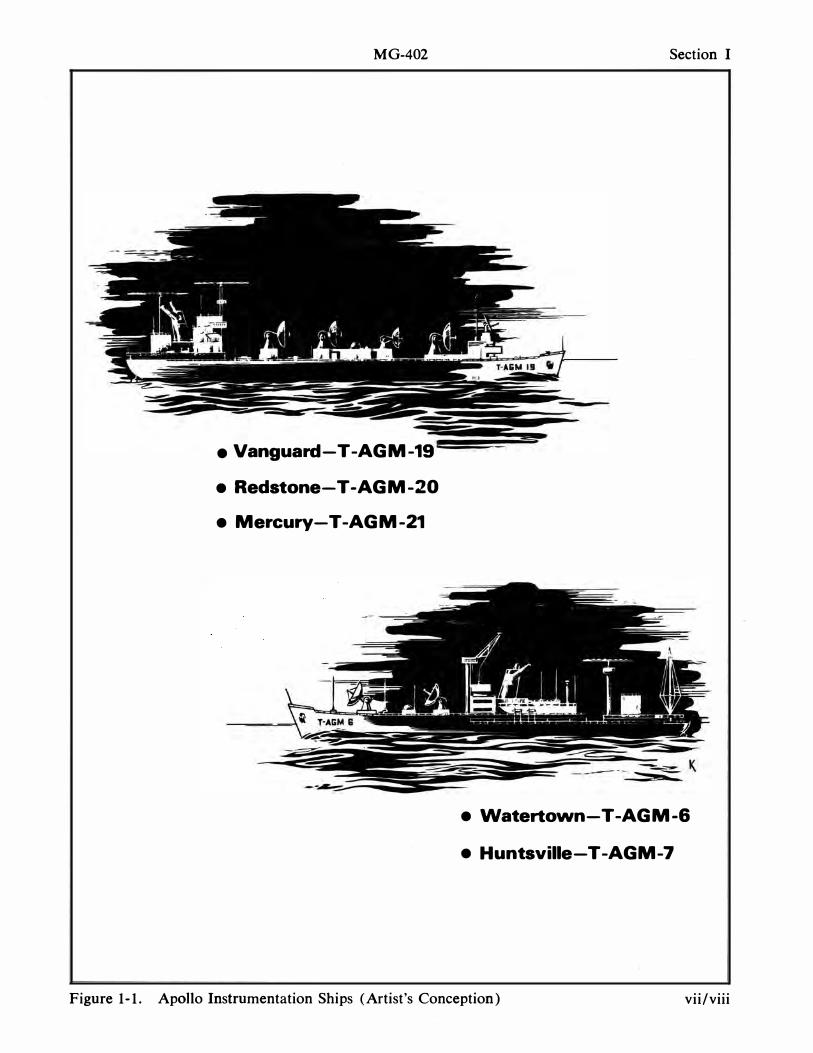
• Vanguard-T-AGM-19
• Redstone-T -AGM-20
• Mercury-T -AGM-21
• Watertown-T -AGM-6
• Huntsville-T -AGM-7
Figure 1-1. Apollo Instrumentation Ships (Artist's Conception) vii/viii
July 2008 Publication Note
The Handbook for Apollo Instrumentation Ships, MG-402, was prepared for shipboard Flight Controllers and technical personnel for their use. It describes the two different classes of Apollo ships to familiarize personnel with the ship’s configuration. The original document was provided by Ed Fendell, Apollo Flight Controller. This PDF version was produced by Bill Wood. The original pages were scanned with an Epson Expression 10000XL, using Silverfast AI Studio, to produce high quality 400 pixel per inch, 48-bit im-ages, for further processing. Each page image was straightened and cleaned up in Photoshop CS3 prior to producing 300 pixel-per-inch EPS page images. Adobe Acrobat 9 Professional was used to prepare the final PDF edition. The document is made searchable by using Adobe ClearScan. Bill Wood was a Unified S-Band Lead Engineer at the Goldstone Apollo MSFN station during the lunar missions. Ed Fendell was the Head, Apollo Communications Sections, Flight Control Operations Branch at JSC during most of the Apollo missions. Both are now retired in Barstow, California and Houston, Texas, USA.
MG-402
I LIST OF EFFECTIVE PAGES I I
TOTAL NUMBER OF PAGES IS 120, AS FOllOWS:
A
Pilge No. Issu_ Title . • • . • . . . . . . . . . . . . Original A through C • . . . . . . . . • . . Original i through viii • . . • . . . • . . . . Original 1-1 through 1-34 . . . . . . . . . Original 5-1 through 5-4 . . . . . . . . . . Original 2-1 through 2-66 . . . . . • . . . Original G-l through G-4 . . . • . . . . . Original Type Face Specimen Sheet .. . Original
• The ut8rlak Indicata. pagea reviaed, added or deleted by the ourrent chaDp.
Issu_
MG-402
RECORD-OF-CHANGES
DATE OF CONTRACTOR & DESCRIPTION DATE OF CONTRACTOR & DESCRIPTION REVISION AUTHORITY OF CHANGE REVISION AUTHORITY OF CHANGE
Reissued Bendix Extensively September 1, NAS 5-10750 rewri tten and
1968 TD-565 updated
B/C
MG-402 Section I
SECTION I CENERAL DESCRIPTION
INTRODUCTION The Manned Space Flight Network
(MSFN) , originally implemented to support Project Mercury, and subsequently, Project Gemini, is now equipped to support the requirements of Project Apollo.
The network consists primarily of stations in the United States and six foreign countries. These stations are geographically situated to provide the most efficient coverage between the latitudes of approximately 35° North and 35° South, where most of the spacecraft orbits are contained.
In support of Project Apollo, five instrumentation ships have been added to the network: three 19-Class, consisting of T-AGM-19, 20, 21 Apollo Instrumentation Ships (AIS) for earth orbital insertion and translunar injection; and two 6-Class, consisting of T -AGM-6, 7 AIS for the reentry phase of the Apollo mission.
PURPOSE OF THE HANDBOOK
This handbook has been prepared to acquaint the shipboard Flight Controllers and technical personnel with their mission, responsibilities, and the facilities available for their use. For some personnel, this may be the first experience aboard a ship. This handbook will help familiarize them with their surroundings, facilities, duties, and naval terminology. This handbook has been prepared for the National Aeronautics and Space Administration (NASA) (GSFC/ISO) by the Bendix Field Engineering Corporation, a subsidiary of The Bendix Corporation, under contract NAS5-9870, and reissued under contract NAS5-10750.
SHIPS' PURPOSE
The Ships have been instrumented and deployed for optimum coverage of the Apollo mission in areas not supported by land stations. These mobile tracking and communication platforms provide the mission with the flexibility required to support all phases from launch to recovery. Figure 1-1 is an artist's conception of both classes of ships as they might appear at sea in support of a mission.
19-CLASS
The flight of the Apollo spacecraft from lift-off to insertion into an earth orbit is programed to a launch azimuth which varies as a function of launch delay from the start of the launch window. This fan of possible launch trajectories is monitored by the Bermuda station in the North and by the Antigua station in the South. Opti
mum data coverage of launch and insertion has a gap in the middle which is filled by an instrumentation ship.
The Apollo spacecraft is injected into
its tran.slunar trajectory after a brief period
in earth orbit. Injection may take place over the Atlantic, Indian, or Pacific Oceans, so the Apollo network data coverage is supplemented by three instrumentation ships.
NASA requires as many as 30 days onstation time in support of Project Apollo. When not supporting Project Apollo, the
ships are assigned to other space programs requiring data acquisition not supported by land-based stations.
1-1
Section I
6-CLASS
MG-402
The declination of the moon determines whether a landing area in the Northern Hemisphere or Southern Hemisphere is affected. Once the landing area has been determined, the two reentry ships are assigned their positions in the landing area.
Another factor affecting the spacecraft landing area is the manner in which reentry into the earth's atmosphere is accomplished. The spacecraft may reenter directly in a minimum lift trajectory or it may reenter via a skipout trajectory. Downrange and crossrange travels from the initial point of entry into the atmosphere as a function of the spacecraft's reentry angle and bank angle are: downrange travel: 1,000 to 5,000 nautical miles, and crossrange travel: ± 250 to ± 500 nautical miles.
The ships assigned to the reentry area are concerned with the blackout areas occurring along the reentry track due to transfer of spacecraft kinetic energy into heat. These areas are of importance for proper choice of position for the reentry ship along the ground track of the spacecraft to permit data acquisition with the spacecraft during the early phase of possible skipout The selection of reentry ship position is not the most favorable one for a particular trajectory, but rather for a family of possible trajectories within the spacecraft's reentry capability.
SHIPS' PERSONNEL The marine crews are Military Sea
Transport Service personnel. The technical personnel are Department of Defense (DOD) contractor engineers and technicians. These personnel are assigned aboard ship for a cruise length determined by their agency. The Flight Controllers
1-2
are assigned by NASA for the individual Apollo missions, and their assignments are determined by mission duration. They normally experience a 5-week tour aboard ship.
REPORTING ABOARD Personnel reporting aboard are met at
the quarterdeck by one of the ship's officers. He directs them to the Ships Operations Manager's (SOM's) office where they are assigned staterooms. In each stateroom are billet cards bearing each man's name, stateroom number, work area assignment, and various emergency station assignments.
19-CLASS
The three 19-Class ships are the USNS Vanguard, USNS Redstone, and USNS Mercury. Each ship carries a NASA station designation as follows: the Vanguard (V AN) , the Redstone (RED) , and the Mercury (MER) . Each ship is manned by 17 officers, 71 crew members, and 122 technical personnel including the NASA Flight Controllers.
6-CLASS
The two 6-Class ships are the USNS Watertown (WTN) and the USNS Huntsville (HTV) . Each ship has a complement of 1 4 officers, 56 crewmen, and 72 technical personnel including the NASA Flight Controllers.
SHIP'S SUPPORT PLANS The ship's support plan is finalized 3
days before DOD missions or more than 30 days before Apollo missions. At this time, the ship starts instrumentation setup and calibration. Such operational details as meterology, equipment warmup and
MG-402 Section I
checkout times, and recorder operating The ships also participate in network times are documented for each mission in drills and simulations while functioning as countdown format. The SOM coordinates part of the NASA MSFN. Flight Conall subsystem activities and reports status troller teams are normally placed aboard to the Range. Final calibrations and 2 or 3 weeks prior to a mission. This time checks are in mission configuration. Sub- is devoted to system testing and maintesystems (telemetry, radar, etc.) are cali- nance, telemetry and display system calibrated first and checked individually, then bration and alignment, and Flight Controlthe complete instrumentation system is ler local and network exercises. Network checked as an integrated data-gathering drills and tests are used to evaluate comstation. munications and data flow paths from op-
Whenever possible, all checks are com- erational areas.
puter controlled and/or monitored to pro- This premission period also allows for
vide controllable conditions and to obtain completion of bathymetric b(lttom-map
quick confirmation of equipment status. ping operations. A bottom area near the
Ship status is monitored through daily ship's desired location (or locations, if
status reports required by Range or Apollo ships are required to move during the mis
Network Control. sion) is selected on the basis of depth
SYSTEM TESTS Before scheduling operations, a series
of shipboard electronic systems tests are performed. These tests include, but are not limited to, any or all of the following:
a. Subsystem Test (SST) -to verify station equipment on a module or subsystem level
b. System Test (ST) -to verify station equipment on a system level
c. Integrated System Test (lST) -to verify interfaced station equipments
d. Station Readiness Test (SRT) -to verify station's overall capability to support a mission
e. Dynamic Operations Test (DOT) to test station equipment in conjunction with the NASA test aircraft
f. Computation and Data Flow Integrated Subsystem Test (CADFISS) -to determine the operational readiness of the MSFN to furnish tracking and data acquisition support for a mission
profile. The area (s) is then mapped, and depth matrices computed. This data is used during tracking periods to provide precise information on the ship's position.
During premiss ion and mission periods, the ships are in radio contact with the Network Control Center. At a specified time, the ships establish mission support communications with other Range stations and report "on-station, ready to support."
TARGET ACQUISITION Telemetary systems are expected to ac
quire the target first. If the target is not acquired by this system, the Designate Controller uses the computer's inflight acquisition information to direct the antennas. All required systems are placed "on track" to collect and transmit tracking and telemetry data and to display and retransmit acquired data.
POST-MISSION OPERATIONS After mission termination, the ships per
form required post-mission calibrations. The SOM completes and sends to the
1-3
Section I MG-402
Range a "quick look" report, which includes general system performance and track times.
Copies of magnetic tape recordings are made. In the case of vehicle malfunctions, some telemetry data playback may be required to investigate specific channels. All original magnetic tape recordings, chart recordings, logs, charts, and other data are packed in special containers for security and protection. Data collected during the Apollo mission is processed and forwarded in accordance with Operations Directive 63-1 (as revised).
After completion of mission support, HF communications, timing, and navigation are maintained. When released, the ship reverts to control of the Range scheduling authority for sailing orders and operating instructions.
SHIPS' PERFORMANCE PARAMETERS
Both classes of ships have been modified from noncommissioned U.S. Navy ships. The 19-Class has undergone extensive structural modification, while the 6-Class structural modifications have been less severe. In both cases, the modifications have converted these ships from their previous tanker configuration and Victory ship configuration into fully instrumented, mobile, space-tracking platforms. Provisions have been made for officers' quarters, crew's quarters, and adequate, comfortable staterooms for the technical personnel and Flight Controllers.
The main deck area and above has been converted into several antenna platforms. Internally, space has been provided for all the various system equipment. Areas for storage of both marine spares and electronic spares are located throughout the ships. These ships have been equipped with both conventional and sophisticated
1-4
navigation systems for pinpoint position accuracy.
The ships have provisions for emergency underway replenishment of fuel, foodstuffs, and other supplies. Both ships are air conditioned in all manned and instrumented spaces.
Distilling equipment to provide fresh water, a roll stabilization system to decrease motions, a recirculating distilled water cooling system for electronic equipment, an emergency generator set, an internal communication system, and related equipment are also on board.
19-CLASS
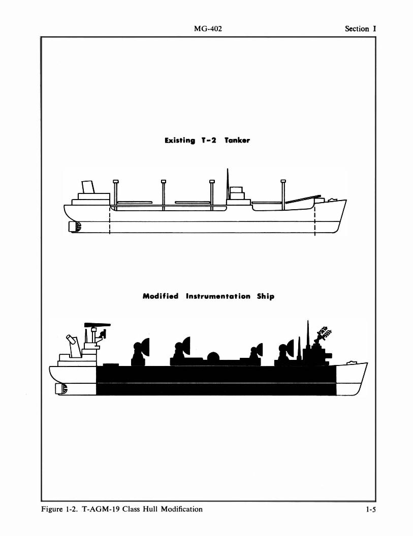
The 19-Class modification consists of joining a T -2 tanker bow and stern section to a new, larger midsection (figure 1-2) to- permit adequate space for instrumentation systems, support equipment, storage, and personnel.
The 19-Class leading particulars are as follows:
• overall length . . . . . . . 595 feet, 5 inches • extreme beam ....... 75 feet • full load draft . . . . . . . 25 feet • full load
displacement ....... . 23,310 tons • tracking speed ...... 13 knots • standard speed . , .... 15 knots • flank speed .... ..... 17 knots • shaft horsepower .... 10,000 • shaft rpm ........... 106 • potable water
capacity ............ 360 tons • fuel oil capacity ..... 3,724 tons • maximum "on-sta-
tion" endurance ..... 20,150 total nautical miles
6-CLASS
The 6-Class are former Victory ships that have undergone conversion to provide
MG-402 Section I
Existing T-2 Tanker
Modified Instrumentation Ship
Figure 1-2. T-AGM-19 Class Hull Modification 1-5
Section I MG-402
support for the reentry phase of Apollo moon flight.
the derway. Each instrumentation machine
The 6-Class leading particulars are as follows:
• overall length ...... . 455 feet, 3 inches • extreme beam . . .. . .. 62 feet • full load draft ... .. . . 23 feet, 7�
inches • full load
displacement . ..... .. 12,199 tons • tracking speed . .... . 13 knots • standard speed ... ... 15 knots • flank speed ... . .... . 16. 5 knots • shaft horsepower .... 6,000 • shaft rpm . .. . ... . . .. 92 • potable water
capacity . . ..... .. ... 168 tons • fuel oil capacity ..... 2,645 tons • maximum "on-sta-
tion" endurance .... . 10,000 total nautical miles
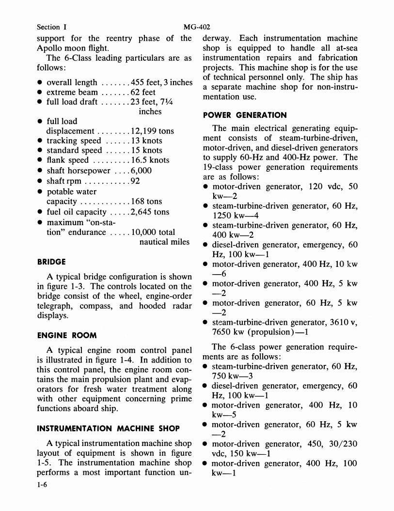
BRIDGE
A typical bridge configuration is shown in figure 1-3. The controls located on the bridge consist of the wheel, engine-order telegraph, compass, and hooded radar displays.
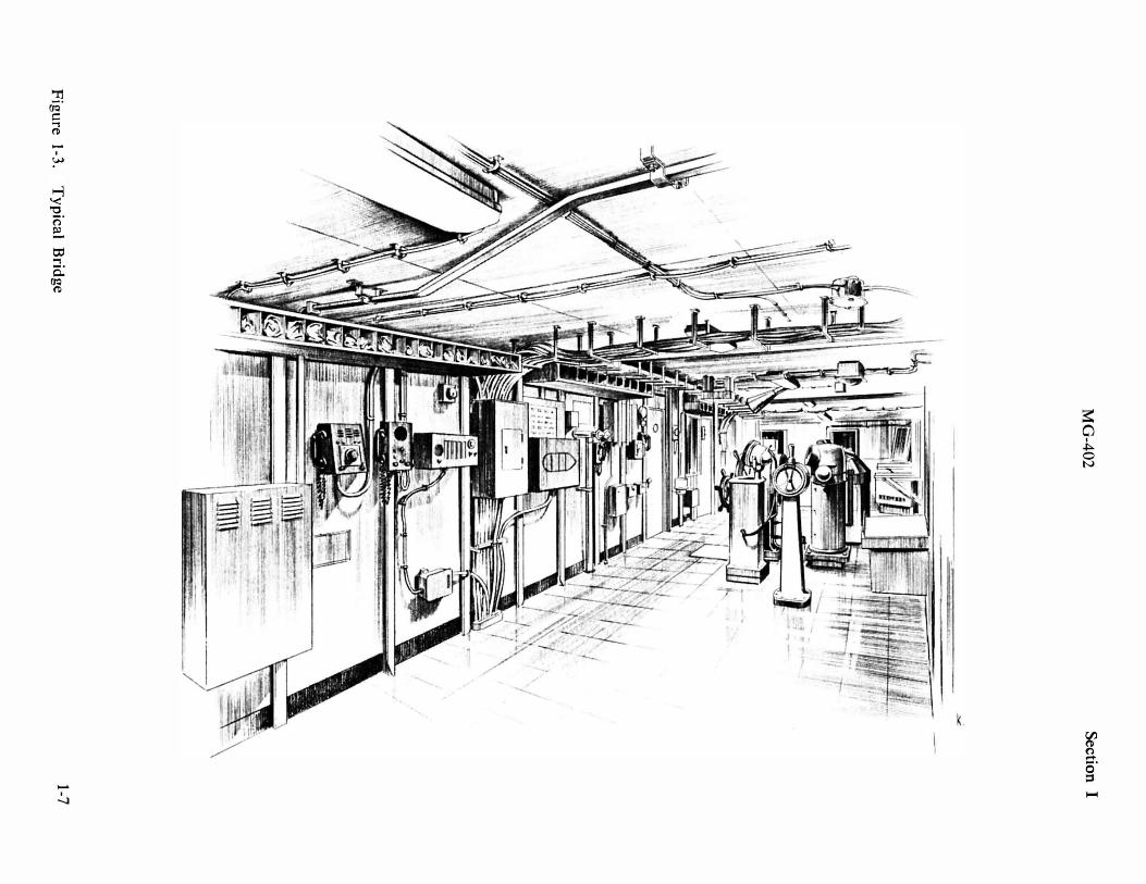
ENGINE ROOM
A typical engine room control panel is illustrated in figure 1-4. In addition to this control panel, the engine room contains the main propulsion plant and evaporators for fresh water treatment along with other equipment concerning prime functions aboard ship.
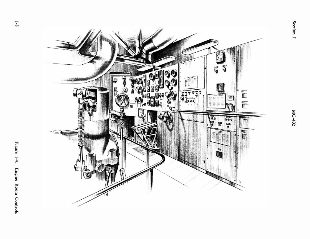
INSTRUMENTATION MACHINE SHOP
· A typical instrumentation machine shop layout of equipment is shown in figure 1-5. The instrumentation machine shop performs a most important function un-
1-6
shop is equipped to handle all at-sea instrumentation repairs and fabrication projects. This machine shop is for the use of technical personnel only. The ship has a separate machine shop for non-instru-mentation use.
POWER GENERATION
The main electrical generating equipment consists of steam-turbine-driven, motor-driven, and diesel-driven generators to supply 60-Hz and 400-Hz power. The 19-c1ass power generation requirements are as follows: • motor-driven generator, 120 vdc, 50
kw-2 • steam-turbine-driven generator, 60 Hz,
1250 kw-4 • steam-turbine-driven generator 60 Hz , ,
400 kw-2 • diesel-driven generator, emergency, 60
Hz, 100 kw-1 • motor-driven generator, 400 Hz, 10 kw
-6 • motor-driven generator, 400 Hz, 5 kw
-2 • motor-driven generator, 60 Hz, 5 kw
-2 • steam-turbine-driven generator, 3610 v,
7650 kw (propulsion)-l
The 6-c1ass power generation requirements are as follows: • steam-turbine-driven generator, 60 Hz,
750 kw-3 • diesel-driven generator, emergency, 60
Hz, 100 kw-1 • motor-driven generator, 400 Hz, 10
kw-5 • motor-driven generator, 60 Hz, 5 kw
-2 • motor-driven generator, 450, 30/230
vdc, 150 kw-1 • motor-driven generator, 400 Hz, 100
kw-1
-
I
�
..I
-...J
..... I
00
.... ,
�
� o o
3
(j o ::s
a Cii
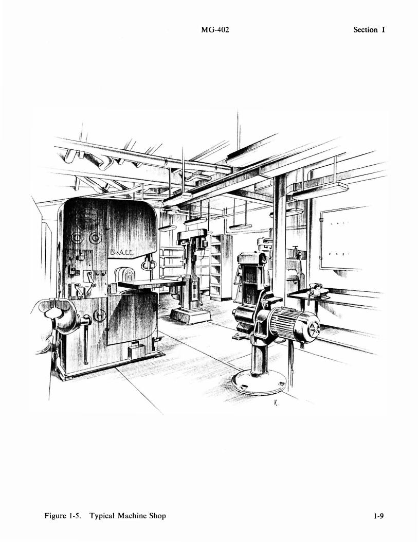
Figure 1-5. Typical Machine Shop
MG-402 Section I
1-9
Section I MG-402
DURATION OF CRUISE
The 1 9-Class and the 6-Class are programed for sea duty periods up to 60 days. Port time for provisioning, refueling, and shore leave is short, but the ships do remain in port during periods between support assignments whenever possible.
A 24-hour-notice sailing condition is observed during these periods. The ports are selected to reduce sailing time from station to port, and return, to a minimum.
POSITIONING
The Ship's Position and Attitude Measurement System ( SP AMS ) furnishes the necessary ship position and attitude data to enable the Central Data Processor to convert C-band radar and unified S-band tracking data outputs from deck-referenced to earth-referenced coordinates. Additional details of the system are in section II of this handbook.
SHIP'S COMMUNICATIONS
The T-AGM-6 and T-AGM- 1 9 Class AIS are equipped with an Instrumentation Communications System and a Ship's Radio System.
The primary function of the instrumentation system is communications support during missions. The system is also used to support the daily nonmission instrumentation operations, such as instrumentation system checkout, handling administrative traffic and range schedules, supply requisitions, emergency messages, etc.
The Ship's Radio System conforms with international maritime regulations for the safety of ships at sea and is used to support the ship's maritime operational requirements including ship-to-ship and ship-to-shore radiotelephone and CW ( Morse code ) .
1-10
Interior communications aboardship link all instrumentation and operations managers with Systems Control. The ship's telephones are used for nonoperational communications. When in port, the ship uses a cable connecting the ship's telephone system with the shore telephone system.
SHIPS' LAYOUT
The Apollo Instrumentation Ships have the necessary facilities for creating a comfortable atmosphere while underway; it i s imperative that every man lend his personal support to the ship's well-being. The Flight Controllers and technicians have semiprivate living quarters with flush and showering facilities ; this area is their responsibility and must be treated as such. However, stewards are provided for making beds and cleaning the quarters.
19-CLASS
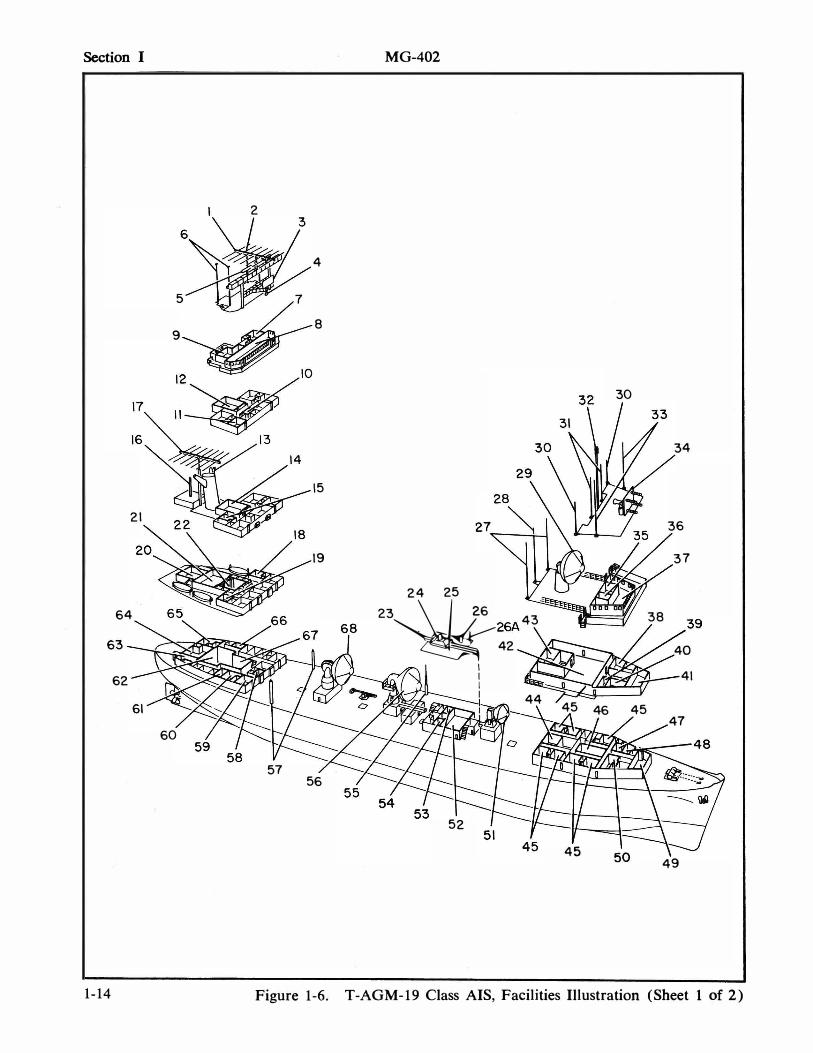
The ship's layout is illustrated in figure 1 -6, which shows the general areas of interest and concern to the Flight Controllers. A self-service laundry is provided with washers, driers, and ironing facilities; other facilities include a commissary, hospital , library, machine shop, offices, etc. A more complete listing can be found in table I-I.
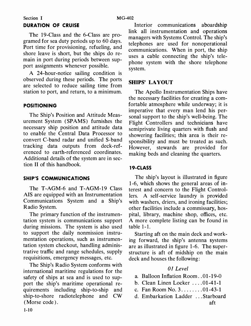
Starting aft on the main deck and working forward, the ship's antenna systems are as illustrated in figure 1 -6 . The superstructure is aft of midship on the main deck and houses the following:
01 Level a. Balloon Inflation Room . . 01-19-0 b. Clean Linen Locker .. . . 01-41-1 c. Fan Room No. 3 . . . . . . . . 01-43-1 d. Embarkation Ladder . . . Starboard
aft
02 Level a. Chief Engineer's Office . . 02-47-1 b. Fan Room No. 2 . . . . . . . 02-43-3 c. Battery Room . . . . . . . . . 02-43-5
03 Level a. Master's Office . . . . . . . . . 03-47-4 b. Gyre Room . . . . . . . . . . . 0 3-45-0 c. Fan Room No. 1 . . . . . . . 03-47-1 d. Clean Linen Locker . . . . . 03-43-1
04 Level a. Chart Room . . . . . . . . . . . 04-45-4 b . Radio Room . . . . . . . . . . 04-45-1 c. Wheelhouse . . . . . . . . . . . . 04-47-0
M G-402 Section I
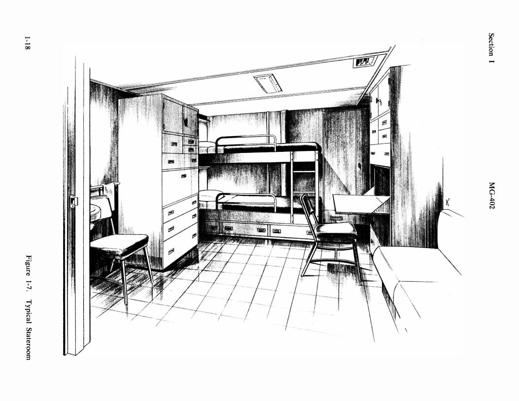
The second deck houses the crew's quarters, the technician's quarters, and most of the ship's domestic services. Figure 1-7 illustrates a typical s tateroom.
The Technicians' Messroom is also on the second deck ( 2-104-0 ) and seats 56 men. Figure 1-8 illustrates a typical messroom arrangement.
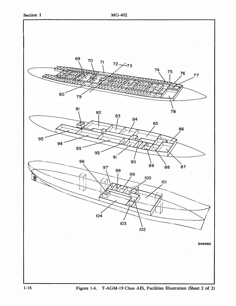
The third deck houses most of the instrumentation and range equipment as illustrated in the deck cutaway, figure 1-6, and in the equipment location illustrations in section II.
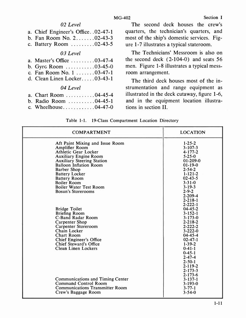
Table 1-1. 19-Class Compartment Location Directory
COMPARTMENT LOCATION
Aft Paint Mixing and Issue Room 1-25-2 Amplifier Room 3-107-3 Athletic Gear Locker 4-177-2 Auxiliary Engine Room 5-25-0 Auxiliary Steering Station 01-209-0 Balloon Inflation Room 01-19-0 Barber Shop 2-54-2 Battery Locker 1-121-2 Battery Room 02-43-5 Boiler Room 3-31-0 Boiler Water Test Room 3-19-3 Bosun's Storerooms 2-9-2
2-209-4 2-218-1 2-222-1
Bridge Toilet 04-45-2 Briefing Room 3-152-1 C-Band Radar Room 3-173-0 Carpenter Shop 2-218-2 Carpenter Storeroom 2-222-2 Chain Locker 3-222-0 Chart Room 04-45-4 Chief Engineer's Office 02-47-1 Chief Steward's Office 1-39-2 Clean Linen Lockers 0-41-1
0-45-1 2-47-4 2-50-1 2-119-2 2-173-3 2-173-6
Communications and Timing Center 3-137-1 Command Control Room 3-193-0 Communications Transmitter Room 3-77-1 Crew's Baggage Room 3-54-0
1-11
Section I M G-402
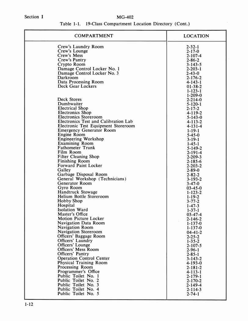
Table 1-1. 19-Class Compartment Location Directory (Cont.)
1-12
COMPARTMENT
Crew's Laundry Room Crew's Lounge Crew's Mess Crew's Pantry Crypto Room Damage Control Locker No. 1 Damage Control Locker No. 3 Darkroom Data Processing Room Deck Gear Lockers
Deck Stores Dumbwaiter Electrical Shop Electronics Shop Electronics Storeroom Electronics Test and Calibration Lab Electronic Test Equipment Storeroom Emergency Generator Room Engine Room Engineering Workshop Examining Room Fathometer Trunk Film Room Filter Cleaning Shop Finishing Room Forward Paint Locker Galley Garbage Disposal Room General Workshop (Technicians) Generator Room Gyro Room Handtruck Stowage Helium Bottle Storeroom Hobby Shop Hospital Isolation Ward Master's Office Motion Picture Locker Navigation Data Room Navigation Room Navigation Storeroom Officers' Baggage Room Officers' Laundry Officers' Lounge Officers' Mess Room Officers' Pantry Operation Control Center Physical Training Room Processing Room Programmer's Office Public Toilet No. 1 Public Toilet No. 2 Public Toilet No. 3 Public Toilet No. 4 Public Toilet No. 5
LOCATION
2-32-1 2-17-0 2-107-4 2-86-2 3-143-5 2-203-1 2-43-0 2-176-2 4-143-1 01-38-2 1-123-1 1-209-0 2-214-0 5-120-1 2-17-2 4-119-2 5-143-0 4-113-2 4-131-4 1-19-1 5-45-0 3-19-1 1-45-1 5-149-2 2-191-4 2-209-3 2-185-6 2-203-2 2-89-0 2-82-2 3-193-2 3-47-0 03-45-0 1-123-2 1-19-2 3-77-2 1-47-3 1-37-1 03-47-4 2-146-2 1-137-0 1-137-0 04-41-2 2-25-2 1-35-2 2-107-5 2-96-1 2-85-1 3-143-2 4-193-0 2-181-2 4-113-1 2-179-1 2-170-2 2-149-4 2-114-3 2-74-1
MG-402 Section I
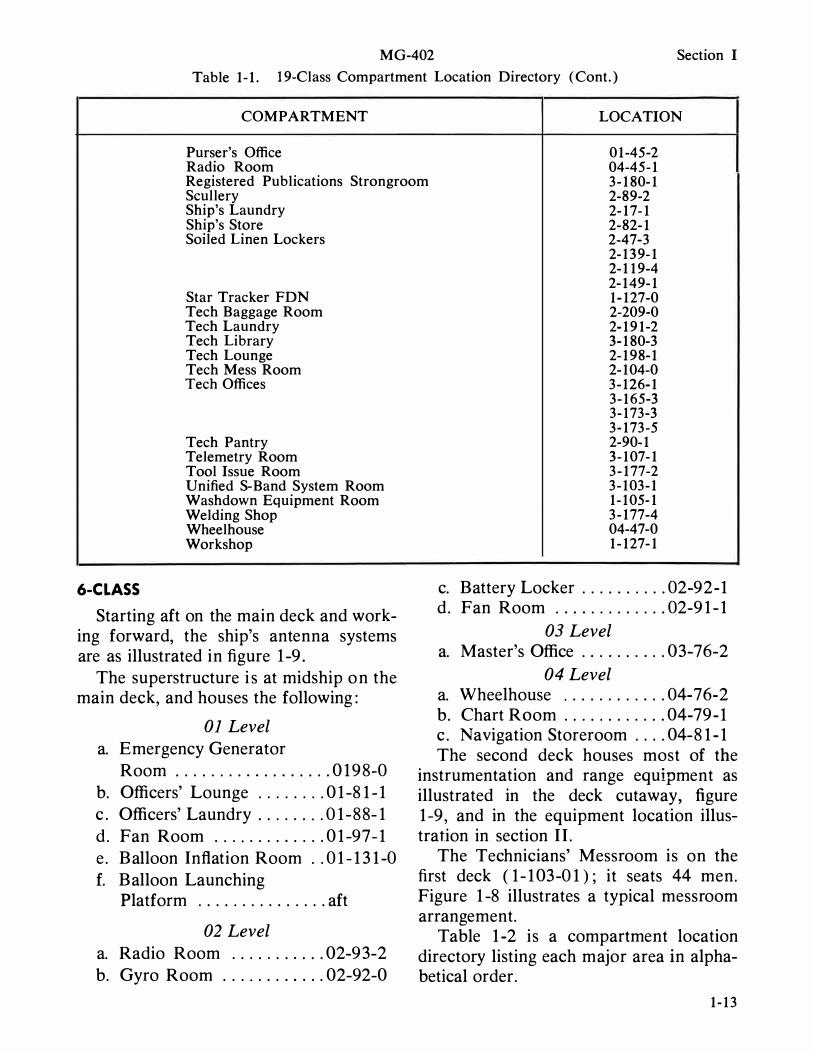
Table 1-1. 19-Class Compartment Location Directory (Cont.)
COMPARTMENT LOCATION
Purser's Office 01-45-2 Radio Room 04-45-1 Registered Publications Strongroom 3-180-1 Scullery Ship's Laundry Ship's Store Soiled Linen Lockers
Star Tracker FDN Tech Baggage Room Tech Laundry Tech Library Tech Lounge Tech Mess Room Tech Offices
Tech Pantry Telemetry Room Tool Issue Room Unified S-Band System Room Washdown Equipment Room Welding Shop Wheelhouse Workshop
6-CLASS
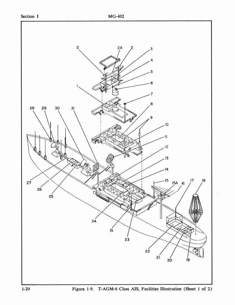
Starting aft on the main deck and working forward, the ship's antenna systems are as illustrated in figure 1 -9 .
The superstructure i s at midship o n the main deck, and houses the following:
01 Level a. Emergency Generator
Room . . . . . . . . . . . . . . . . . . 0 1 9 8-0 b. Officers' Lounge . . . . . . . . 0 1 -8 1 - 1 c . Officers' Laundry . . . . . . . . 0 1 -88- 1 d . Fan Room . . . . . . . . . . . . . 0 1 -97- 1 e . Balloon Inflation Room . . 0 1 - 1 3 1 -0 f. Balloon Launching
Platform . . . . . . . . . . . . . . . aft
02 Level a. Radio Room . . . . . . . . . . . 02-9 3-2 b. Gyro Room . . . . . . . . . . . . 02-92-0
2-89-2 2-17-1 2-82-1 2-47-3 2-139-1 2-119-4 2-149-1 1-127-0 2-209-0 2-191-2 3-180-3 2-198-1 2-104-0 3-126-1 3-165-3 3-173-3 3-173-5 2-90-1 3-107-1 3-177-2 3-103-1 1-105-1 3-177-4 04-47-0 1-127-1
c. Battery Locker . . . . . . . . . . 02-92-1 d . Fan Room . . . . . . . . . . . . . 02-9 1 - 1
03 Level a. Master's Office . . . . . . . . . . 03-76-2
04 Level a. Wheelhouse . . . . . . . . . . . . 04-76-2 b. Chart Room . . . . . . . . . . . . 04-79-1 c . Navigation Storeroom . . . . 04-8 1 - 1 The second deck houses most of the
instrumentation and range equipment as illustrated in the deck cutaway, figure 1 -9 , and in the equipment location illustration in section II .
The Technicians' Messroom is on the first deck ( 1 - 1 03-0 1 ) ; it seats 44 men. Figure 1 -8 illustrates a typical messroom arrangement.
Table 1 -2 is a compartment location directory listing each major area in alphabetical order.
1-13
Section I
9
21
64
62
60
1-14
2
4
8
15
19
57 56
MG-402
30
34
36
37
24 25
23*6 43
""
38
42 � 40
. 26A�39
1 41 I
I 44 .,(V:!�iS��m-_ 45 46 45
52
45
47
49
Figure 1-6. T-AGM-19 Class AIS, Facilities Illustration (Sheet 1 of 2)
MG-402 Section I
LEGEND FOR T-AGM-19 CLASS AIS (FIGURE 1-6, SHEET 1)
1. HF LOG PERIODIC ANTENNA 34. RF COMMAND QUAD HELIX (KING POST) ANTENNA
2. LORAN WHIP ANTENNA 35. CHART ROOM 3. LOW-GAIN TELEMETRY ANTENNA 36. NAVIGATION STOREROOM 4. DIRECTION FINDER ANTENNA 37. BRIDGE 5. NAVIGATION RADAR 38. FIRST OFFICER'S STATEROOM 6. SHIP'S COMMUNICATIONS WHIP 39. FAN ROOM
ANTENNAS 40. MASTER'S OFFICE 7. CHART ROOM 41. MASTER'S STATEROOM 8. WHEELHOUSE 42. SATCOM EQUIPMENT ROOM 9. RADIO ROOM 43. AMPLIDYNE ROOM
10. GYRO ROOM 44. FAN ROOM 11. FAN ROOM 45. TECHNICIANS' STATEROOMS 12. GENERATOR ROOM HATCH 46. FAN ROOM 13. TELEVISION ANTENNA 47. THIRD OFFICER'S STATEROOM 14. GENERATOR ROOM HATCH 48. FOURTH OFFICER'S STATEROOM 15. FAN ROOM 49. ELECTRONICS SPARE PARTS 16. HF FOLDED MONOPOLE (HAIRPIN) STOREROOM
ANTENNA (BALLOON DECK) 50. SECOND OFFICER'S STATEROOM 17. HF LOG PERIODIC ANTENNA 51. C-BAND RADAR ANTENNA
(BALLOON DECK) 52. NAVIGATION ROOM 18. PURSER'S OFFICE 53. NAVIGATION DATA ROOM 19. FAN ROOM 54. WORKSHOP 20. BALLOON INFLATION ROOM 55. TELEMETRY TRANSMITTER 21. BOILER CASING ANTENNA BEACON 22. GENERATOR ROOM HATCH 56. UNIFIED S-BAND SYSTEM 23. OPTICAL TUNNEL ANTENNA 24. STAR TRACKER ENCLOSURE 57. HF FOLDED MONOPOLE (HAIRPIN) 25. WHIP ANTENNA ANTENNA (PORT AND STARBOARD) 26. OPTICAL DIRECTOR 58. MEDICAL STOREROOM 26A. SRN 9 ANTENNA 59. SICKBAY 27. COMMUNICATIONS WHIP 60. EXAMINING ROOM
ANTENNA 61. ISOLATION WARD 28. LORAN WHIP ANTENNA 62. BOILER CASING 29. SATCOM ANTENNA 63. EMERGENCY GENERATOR ROOM 30. HF COMMUNICATIONS RECEIVING
WHIP ANTENNA (20 FT) 64. METEOROLOGICAL ROOM
31. HF COMMUNICATIONS RECEIVING 65. HELIUM BOTTLE STOREROOM WHIP ANTENNA (25 FT) 66. FAN ROOM
32. DIRECTION FINDER ANTENNA 67. GENERATOR ROOM HATCH 33. HF COMMUNICATIONS RECEIVING 68. MEDIUM GAIN TELEMETRY
WHIP ANTENNA (35 FT) ANTENNA
1-15
Section I
1-16
69 70
81
MG-402
72�73 "
, , 75 77
88 87
---------=------� 102 -----
3146965
Figure 1-6. T-AGM-19 Class AIS, Facilities Illustration (Sheet 2 of 2)
MG-402 Section I
LEGEND FOR T -AGM-19 CLASS AIS (FIGURE 1-6, SHEET 2)
69. GALLEY 88. TECHNICAL LIBRARY 70. TECHNICIANS' MESSROOM 89. TECHNICAL OFFICE 7l. CREW'S MESS ROOM 90. INSTRUMENTATION (RESERVED) 72. CREW'S QUARTERS 9l. BRIEFING ROOM 73. TECHNICIAN'S QUARTERS 92. CRYPTOGRAPHY ROOM 74. PROCESSING ROOM 93. COMMUNICATIONS AND TIMING 75. FINISHING ROOM CENTER 76. FILM VIEWING AND EDITING 94. UNIFIED S-BAND ROOM
ROOM 95. COMMUNICATIONS TRANSMITTER 77. TECHNICIANS' LAUNDRY ROOM 78. TECHNICIANS' LOUNGE 96. TECHNICAL OFFICE 79. OFFICERS' LOUNGE 97. ELECTRONIC'TEST AND CALI-80. OFFICERS' MESSROOM BRATION LABORATORY 8l. AIR DATA PICKUP KIT 98. ELECTRONICS SHOP
STOREROOM 99. TEST EQUIPMENT STOREROOM 82. TELEMETRY ROOM 100. ELECTRONICS STOREROOM 83. MISSION CONTROL CENTER 101. INSTRUMENTATION (RESERVED) 84. OPERATION CONTROL CENTER 102. SYNCHRO EQUIPMENT ROOM 85. C-BAND RADAR ROOM 103. MOTOR GENERATOR AND 86. TECHNICIANS' WORKSHOP AMPLIDYNE ROOM 87. COMMAND CONTROL ROOM 104. DATA PROCESSING ROOM
1-17
..... I
..... 00
..... I
:--I
-
s:: a
I
� o N
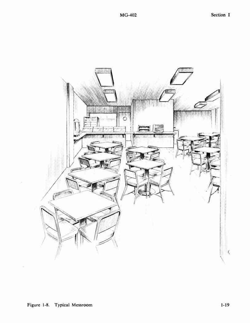
Figure 1-8. Typical Messroom
D . . '
MG-402 Section I
1-19
Section I
1-20
MG-402
2
23
3
20 19
17 18
Figure 1-9. T-AGM-6 Class AIS, Facilities Illustration (Sheet 1 of 2)
MG-402 Section I
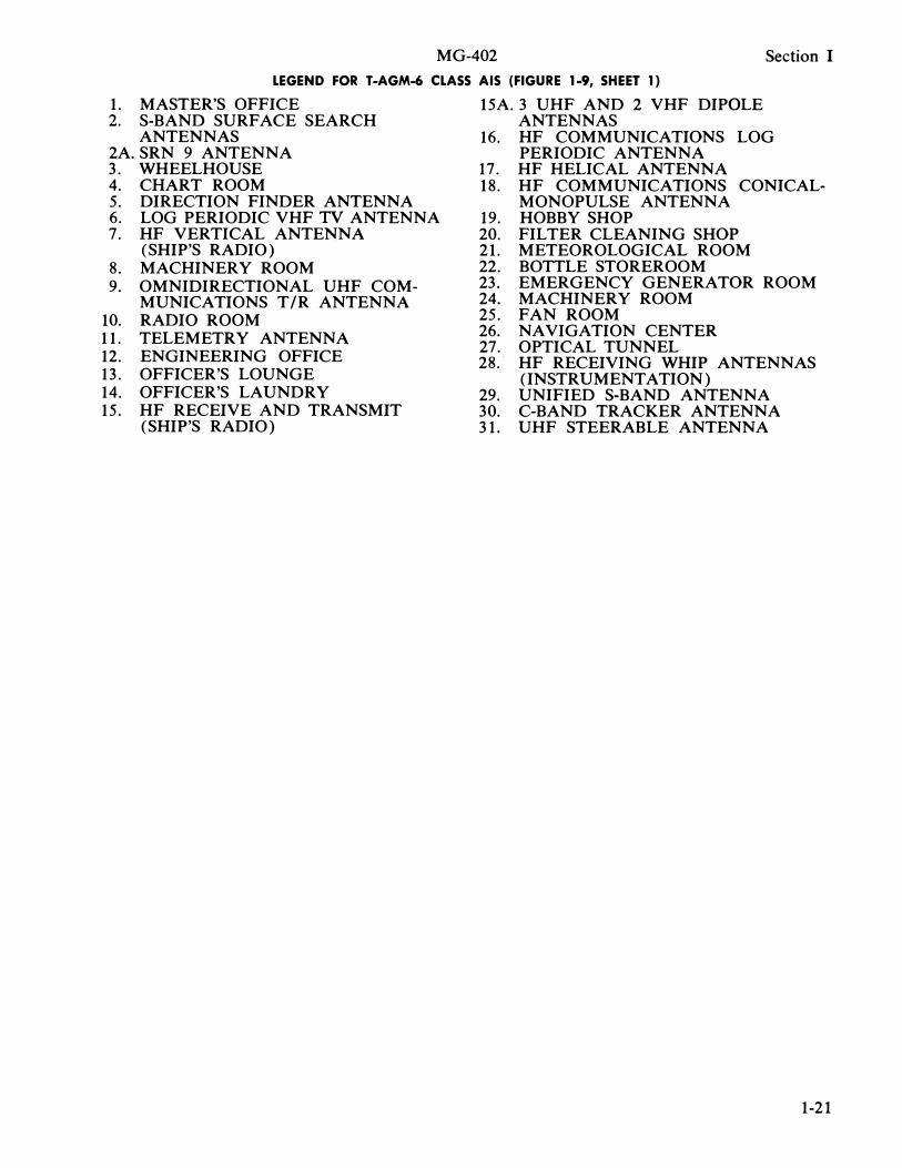
LEGEND FOR T-AGM-6 CLASS AIS (FIGURE 1-9, SHEET 1)
1. MASTER'S OFFICE 2. S-BAND SURFACE SEARCH
ANTENNAS 2A. SRN 9 ANTENNA 3. WHEELHOUSE 4. CHART ROOM 5. DIRECTION FINDER ANTENNA 6. LOG PERIODIC VHF TV ANTENNA 7. HF VERTICAL ANTENNA
(SHIP'S RADIO) 8. MACHINERY ROOM 9. OMNIDIRECTIONAL UHF COM-
MUNICATIONS T /R ANTENNA 10. RADIO ROOM 11. TELEMETRY ANTENNA 12. ENGINEERING OFFICE 13. OFFICER'S LOUNGE 14. OFFICER'S LAUNDRY 15. HF RECEIVE AND TRANSMIT
(SHIP'S RADIO)
15A. 3 UHF AND 2 VHF DIPOLE ANTENNAS
16. HF COMMUNICATIONS LOG PERIODIC ANTENNA
17. HF HELICAL ANTENNA 18. HF COMMUNICATIONS CONICAL-
MONOPULSE ANTENNA 19. HOBBY SHOP 20. FILTER CLEANING SHOP 21. METEOROLOGICAL ROOM 22. BOTTLE STOREROOM 23. EMERGENCY GENERATOR ROOM 24. MACHINERY ROOM 25. FAN ROOM 26. NAVIGATION CENTER 27. OPTICAL TUNNEL 28. HF RECEIVING WHIP ANTENNAS
(INSTRUMENTATION) 29. UNIFIED S-BAND ANTENNA 30. C-BAND TRACKER ANTENNA 31. UHF STEERABLE ANTENNA
1-21
Section I
32 33
40
59--��
1-22
MG-402
73
71
3146571
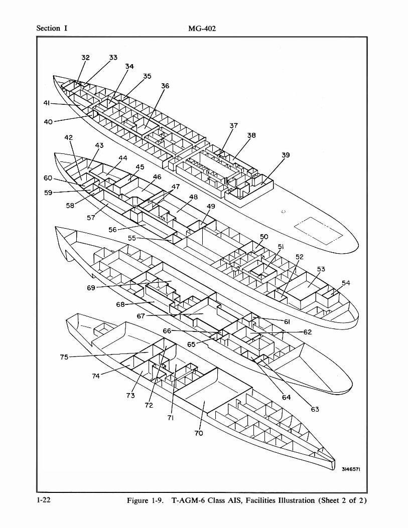
Figure 1-9. T-AGM-6 Class AIS, Facilities Illustration (Sheet 2 of 2)
MG-402 Section I
LEGEND FOR T-AGM-6 CLASS AIS (FIGURE 1-9, SHEET 2)
32. M.G. ROOM (S-BAND) 33. TECHNICAL BAGGAGE ROOM 34. TECHNICIANS' LAUNDRY 35. TECHNICIANS' STATEROOMS 36. NAVIGATION CENTER 37. PURSER'S OFFICE 38. CREW'S MESSROOM 39. TECHNICIANS' MESSROOM 40. TECHNICIANS' STATEROOMS 41. TECHNICIANS' LOUNGE 42. FILM EDITING AND VIEWING
ROOM 43. ELECTRONIC STOREROOM 44. TECHNICIANS' LIBRARY AND
BRIEFING ROOM 45. UNIFIED S-BAND SYSTEM
AMP ROOM 46. UNIFIED S-BAND SYSTEM ROOM 47. TECHNICAL OFFICE 48. TELEMETRY ROOM 49. SYNCHRO ROOM 50. CREW'S LOUNGE 51. HOSPITAL (SICKBAY) 52. CREW'S LAUNDRY 53. COMMUNICATIONS TRANSMITTER
ROOM
54. BARBER SHOP 55. CRYPTO ROOM 56. COMMUNICATIONS AND TIMING
CENTER 57. OPERATIONS CONTROL CENTER 58. DARKROOM 59. PROCESSING ROOM 60. FINISHING ROOM 6 1. CREW'S BAGGAGE ROOM 62. MACHINE SHOp· 63. WELDING SHOP 64. ELECTRICAL SHOP 65. TECHNICIANS' BAGGAGE ROOM 66. OFFICERS' BAGGAGE ROOM 67. MACHINERY SPACE 68. C-BAND RADAR ROOM 69. DATA PROCESSING ROOM 70. MACHINERY SPACE 71. ELECTRONICS STOREROOM 72. ELECTRONICS STOREROOM 73. GENERAL WORKSHOP 74. ELECTRONICS SHOP 75. ELECTRONICS TEST AND
CALIBRATION SHOP
1-23
Section I MG-402
1-24
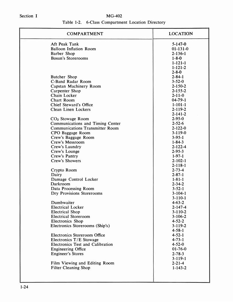
Table 1-2. 6-Class Compartment Location Directory
COMPARTMENT
Aft Peak Tank Balloon Inflation Room Barber Shop Bosun's Storerooms
Butcher Shop C-Band Radar Room Capstan Machinery Room Carpenter Shop Chain Locker Chart Room Chief Steward's Office Clean Linen Lockers
C02 Stowage Room Communications and Timing Center Communications Transmitter Room CPO Baggage Room Crew's Baggage Room Crew's Messroom Crew's Laundry Crew's Lounge Crew's Pantry Crew's Showers
Crypto Room Dairy Damage Control Locker Darkroom Data Processing Room Dry Provisions Storerooms
Dumbwaiter Electrical Locker Electrical Shop Electrical Storeroom Electronics Shop Electronics Storerooms (Ship's)
Electronics Storeroom Office Electronics TIE Stowage Electronics Test and Calibration Engineering Office Engineer's Stores
Film Viewing and Editing Room Filter Cleaning Shop
LOCATION
5-147-0 01-131-0 2-136-1 1-8-0 1-121-1 1-121-2 2-8-0 2-84-1 3-52-0 2-150-2 2-155-2 2-11-0 04-79-1 1-101-1 2-119-2 2-141-2 2-95-0 2-52-6 2-122-0 3-119-0 3-95-1 1-84-3 2-122-4 2-95-3 1-97-1 2-102-1 2-118-1 2-73-4 2-87-1 1-81-1 2-34-2 3-52-1 3-104-1 3-110-1 4-63-2 2-147-4 3-110-2 3-106-2 4-52-2 3-119-2 4-58-1 4-52-1 4-73-1 4-52-0 01-76-0 2-78-3 3-119-1 2-21-4 1-143-2
MG-402
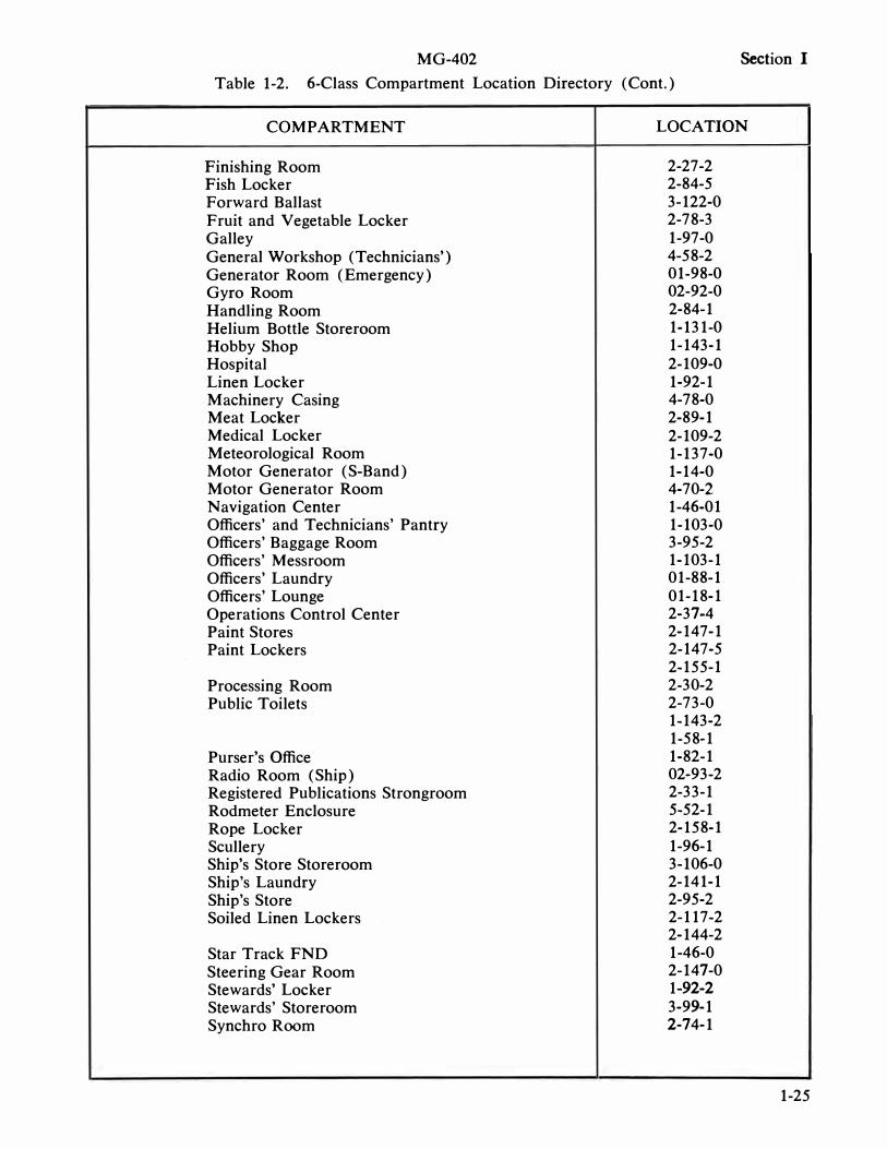
Table 1-2. 6-Class Compartment Location Directory (Cont.)
Section I
COMPARTMENT LOCATION
Finishing Room 2-27-2 Fish Locker 2-84-5 Forward Ballast 3-122-0 Fruit and Vegetable Locker 2-78-3 Galley 1-97-0 General Workshop (Technicians') 4-58-2 Generator Room (Emergency) 01-98-0 Gyro Room 02-92-0 Handling Room 2-84-1 Helium Bottle Storeroom 1-131-0 Hobby Shop 1-143-1 Hospital 2-109-0 Linen Locker 1-92-1 Machinery Casing 4-78-0 Meat Locker 2-89-1 Medical Locker 2-109-2 Meteorological Room 1-137-0 Motor Generator (S-Band) 1-14-0 Motor Generator Room 4-70-2 Navigation Center 1-46-01 Officers' and Technicians' Pantry 1-103-0 Officers' Baggage Room 3-95-2 Officers' Messroom 1-103-1 Officers' Laundry 01-88-1 Officers' Lounge 01-18-1 Operations Control Center 2-37-4 Paint Stores 2-147-1 Paint Lockers 2-147-5
2-155-1 Processing Room 2-30-2 Public Toilets 2-73-0
1-143-2 1-58-1
Purser's Office 1-82-1 Radio Room (Ship) 02-93-2 Registered Publications Strongroom 2-33-1 Rodmeter Enclosure 5-52-1 Rope Locker 2-158-1 Scullery 1-96-1 Ship's Store Storeroom 3-106-0 Ship's Laundry 2-141-1 Ship's Store 2-95-2 Soiled Linen Lockers 2-117-2
2-144-2 Star Track FND 1-46-0 Steering Gear Room 2-147-0 Stewards' Locker 1-92-2 Stewards' Storeroom 3-99-1 Synchro Room 2-74-1
1-25
Section I M G-402
Table 1-2. 6-CJass Compartment Location Directory (Cont.)
COMPARTMENT LOCATION
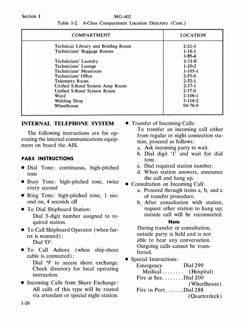
Technical Library and Briefing Room 2-21-1 Technicians' Baggage Rooms 1-16-1
3-95-4 Technicians' Laundry 1-31-0 Technicians' Lounge 1-20-2 Technicians' Messroom 1-103-1 Technicians' Office 2-55-0 Telemetry Room 2-52-1 Unified S-Band System Amp Room 2-37-1 Unified S-Band System Room Ward Welding Shop Wheelhouse
INTERNAL TELEPHONE SYSTEM
The following instructions are for operating the internal communications equipment on board the AIS.
PABX INSTRUCTIONS
• Dial Tone: continuous, high-pitched tone
• Busy Tone: high-pitched tone, twice every second
• Ring Tone: high-pitched tone, 1 second on, 4 seconds off
• To Dial Shipboard Station: Dial 3-digit number assigned to required station.
• To Call Shipboard Operator (when furret is manned ) :
Dial '0'. • To Call Ashore (when ship-shore
cable is connected ) : Dial '9' to access shore exchange. Check directory for local operating instruction.
• Incoming Calls from Shore Exchange:
1-26
All calls of this type will be routed via attendant or special night station.
2-37-0 2-106-1 3- 116-2 04-76-0
• Transfer of Incoming Calls: To transfer an incoming call either from regular or night connection station, proceed as follows: a. Ask incoming party to wait. b. Dial digit ' 1 ' and wait for dial
tone. c. Dial required station number. d. When station answers, announce
the call and hang up. • Consultation on Incoming Call:
a. Proceed through items a, b, and c of transfer procedure.
b. After consultation with station, request other station to hang up; outside call will be reconnected.
Note
During transfer or consultation, outside party is held and is not able to hear any conversation. Outgoing calls cannot be transferred.
• Special Instructions: Emergency Dial 299
Medical . . . . . . . . (Hospital) Fire at Sea . . . . . . . . Dial 200
( Wheelhouse ) Fire i n Port . . . . . . . Dial 288
( Quarterdeck )
M G-402 Section I
LIVING QUARTERS
All the normal hotel facilities are included on board for personnel comfort and convenience. Included in the following paragraphs are descriptions of the individual facilities which provide hoteltype comfort.
STATEROOMS
A typical stateroom ( figure 1-7 ) contains two berths, two secretary bureaus with chairs, and two wardrobes . Bookracks and complete semiprivate lavatory facilities are included on the 1 9-Class.
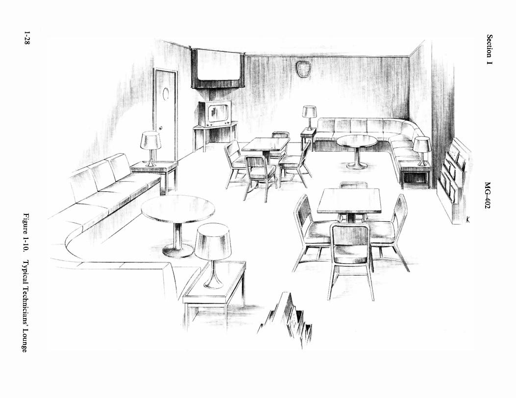
TECHNICIANS' LOUNGE
The technicians' lounge is large and comfortable. It is equipped with tables and chairs for card games, lounge chairs for reading, magazine racks, bulletin board, and bookcases ( figure 1 - 1 0 ) . Movie and television facilities are also available.
TECHNICIANS' MESSROOM
The technicians' messroom seats approximately 56 men at the tables. It has two double serving tables and a drinking fountain ( figure 1-8). The galley is between the technicians' messroom and the crew's messroom.
SHIP'S STORE
The ship's store has sales counters, display cases, and stock shelves. Most personal at-sea needs may be purchased in the ship's store. For example, cigarettes, pipe tobacco, razor blades, shirts, underwear, and khaki and denim trousers are all stocked by the store.
PHYSICAL TRAINING ROOM
The physical training room is well equipped with card tables and chairs, exercise mats, ping pong tables, a horse and
horse mat, punching bag, and weights. Additional miscellaneous equipment is planned for the physical training room.
TECHNICIANS' LAUNDRY
The laundry facilities have three washers, three dryers, and ironing equipment.
BARBER SHOP
The barber shop is modern and well equipped. There is a chair, sterilizer, and the necessary cabinets and mirrors mounted on the bulkhead. Figure 1 - 1 1 shows the barber shop.
MEDICAL FACILITIES
Above average seagoing medical facilities are found on board. A hospital with bunks and clothes lockers ; an examining room with excellent supplies and capabilities ; an isolation ward with bunks, clothing stowage and secretary bureau; and an isolation bath along with a ward bath are provided. The medical facility is staffed by a U. S . Navy medical corpsman. Figure 1 - 1 2 illustrates a typical hospital.
Note
No dental facilities are assigned to these ships.
TECHNICAL LIBRARY
The technical library contains tables, chairs, various files, a microfilm reader and printer, and the technical library unit. Figure 1 - 1 3 illustrates a typical library. Aboard the 6-Class, the library also serves as a briefing room; the 1 9-Class h as a separate briefing room.
ENTERTAINMENT
Movies are shown at certain times in the lounge. Television i s available when the ship is near enough to land. Entertainment antennas are on board, and radios may be used in the staterooms.
1-27
-
I
N 00
-
I
-
o
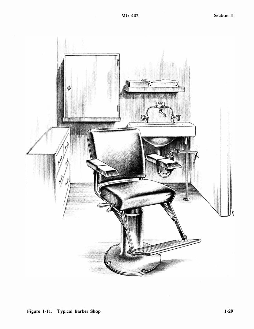
Figure 1-11. Typical Barber Shop
MG-402 Section I
K ,
1-29
Section II
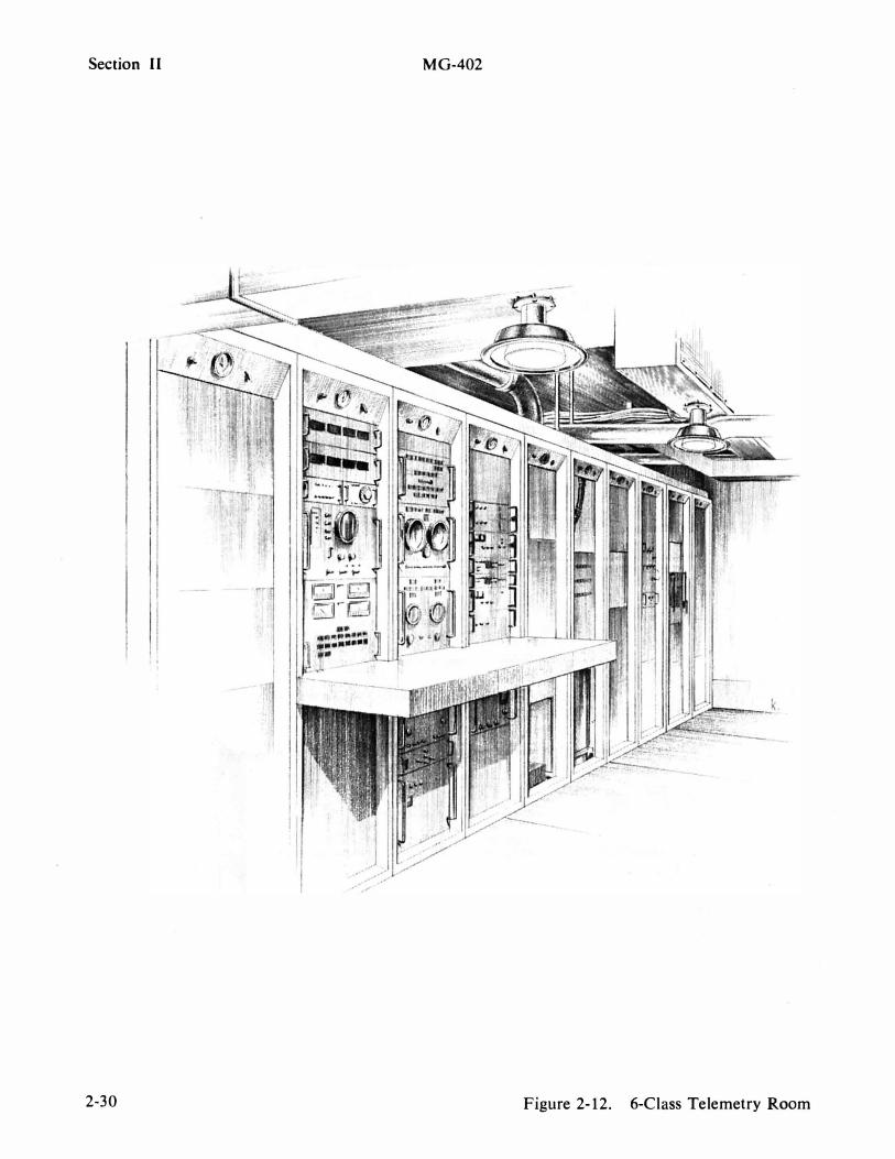
2-30
MG-402
Figure 2-12. 6-Class Telemetry Room

MG-402 Safety
SAFETY
SHIPS' SAFETY PRECAUTIONS
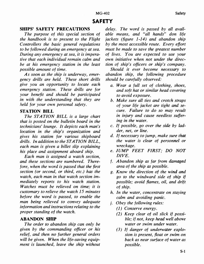
The purpose of this special section of the handbook is to present to the Flight Controllers the basic general regulations to be followed during an emergency at sea. During any emergency at sea, it is imperative that each individual remain calm and be at his emergency station in the least possible amount of time.
As soon as the ship is underway, emergency drills are held. These short drills give you an opportunity to locate each emergency station. These drills are for your benefit and should be participated in with the understanding that they are held for your own personal safety.
STATION BILL
The STATION BILL is a large chart that is posted on the bulletin board in the technicians' lounge. It depicts each man's location in the ship's organization and gives his station for various shipboard drills. In addition to the STATION BILL, each man is given a billet slip explaining his place and assignment aboard ship.
Each man is assigned a watch section, and these sections are numbered. Therefore, when the word is passed that the first section (or second, or third, etc.) has the watch, each man in that watch section immediately reports to his watch station. Watches must be relieved on time; it is customary to relieve the watch 15 minutes before the word is passed, to enable the man being relieved to convey adequate information and instructions relating to the proper standing of the watch.
ABANDON SHIP
The order to abandon ship can only be given by the commanding officer or his relief, and then no further general orders will be given. When the life-saving equipment is launched, leave the ship without
delay. The word is passed by all available means, and "all hands" don life jackets (figure 1-14) and abandon ship by the most accessible route. Every effort must be made to save the greatest number of lives. You are expected to use your own initiative when not under the direction of ship's officers or ship's company.
Should it ever become necessary to abandon ship, the following procedure should be carefully observed:
a. Wear a full set of clothing, shoes, and soft hat or similar head covering to avoid exposure.
b. Make sure all ties and crotch straps of your life jacket are tight and secure. Failure to do so may result in injury and cause needless suffering in the water.
c. If possible, go over the side by ladder, net, or line.
d. If necessary to jump, make sure that the water is clear of personnel or wreckage.
e. JUMP FEET FIRST; DO NOT
DIVE.
f. A bandon ship as far from damaged area of the ship as possible.
g. Know the direction of the wind and go to the windward side of ship if possible; avoid {tames, oil, and drift of ship.
h. In the water, concentrate on staying calm and avoiding panic.
j. Obey the following rules:
(1) Conserve energy.
(2) Keep clear of oil slick if possible; if not, keep head well above water or swim under water.
(3) If danger of underwater explosion is present, {toat or swim on back as near surface of water as possible.
8-1
Safety MG-402
(4) Stay in groups for safety and to RESTRICTED AREAS
facilitate rescue. Restricted areas are clearly marked, and (5) If ship is sinking rapidly, swim only authorized personnel are allowed to
clear promptly and tow injured enter. Retricted areas are so designated men clear to avoid suction effect. for both the safety of the individual and
Figure 1-14 contains instructions for don- the safety of the ship. ning life jackets and the care and stowage
WATER CONSERV ATION of your life jacket.
FIRE
Fire must be reported at once. Too often, fires have gone out of control because the first man to discover the fire tried to put it out by himself. Use any means to spread the alarm. Pass the word clearly and distinctly, giving the frame numbers, the side of the ship, and the compartment number or name; for example: "FIRE! FIRE, FIRE second deck, frame 82, starboard side, ship's store." If you are not qualified to fight fires, leave the area when help arrives.
EMERGENCY TRAFFIC FLOW
Shipboard emergency traffic flow is as follows:
• Forward and up on the starboard side
• Down and aft on the port side This prevents men from running into
each other or jamming narrow passages.
REFUELING
Refueling is carried out by the ship's company, and everyone aboard must abide by the following regulations:
No naked lights, lighted cigarettes, or electrical apparatus that is liable to spark are permitted within 50 feet of a fuel line, tank, compartment containing the tank, or the vent from the tank. No person is allowed to enter a fuel tank until the tank has been freed of vapor and the required precautions have been taken.
These regulations apply to all hands when refueling both at dockside and underway.
S-2
Water conservation while underway is the responsibility of all hands. The most important area in which to conserve water is in personal hygiene. When showering, the following procedure is to be adhered to: • Turn on shower; wet entire body • Turn off shower; soap entire body • Turn on shower; rinse body
The conversion of salt water to fresh water (drinking, bathing, etc.) is a slow process, and once a ship uses more water than it can process, everyone is affected. WATER RESTRICTIONS MAY RESULT. Under certain conditions, a shortage of fresh water may affect the safety of the personnel and the ship.
RF-RADIATION HAZARD
WARNING
The purpose of the Radiation Hazard Warning System is to ensure the safety of ship's personnel and personnel operating Instrumentation Complexes against RF radiation.
There are two warning systems. The primary system provides an audio warning tone at the beginning and end of any USBS, C-band, or command control antenna RF radiation period. The tone is 5 seconds continuous (beginning) and 1 second on, 1 second off for a period of 5 seconds (end), and is broadcast over the general announcing system (l Mc). In addition, red lights located at each personnel access to the main decks forward of frame 46 blink on and off for the duration of the RF radiation period.
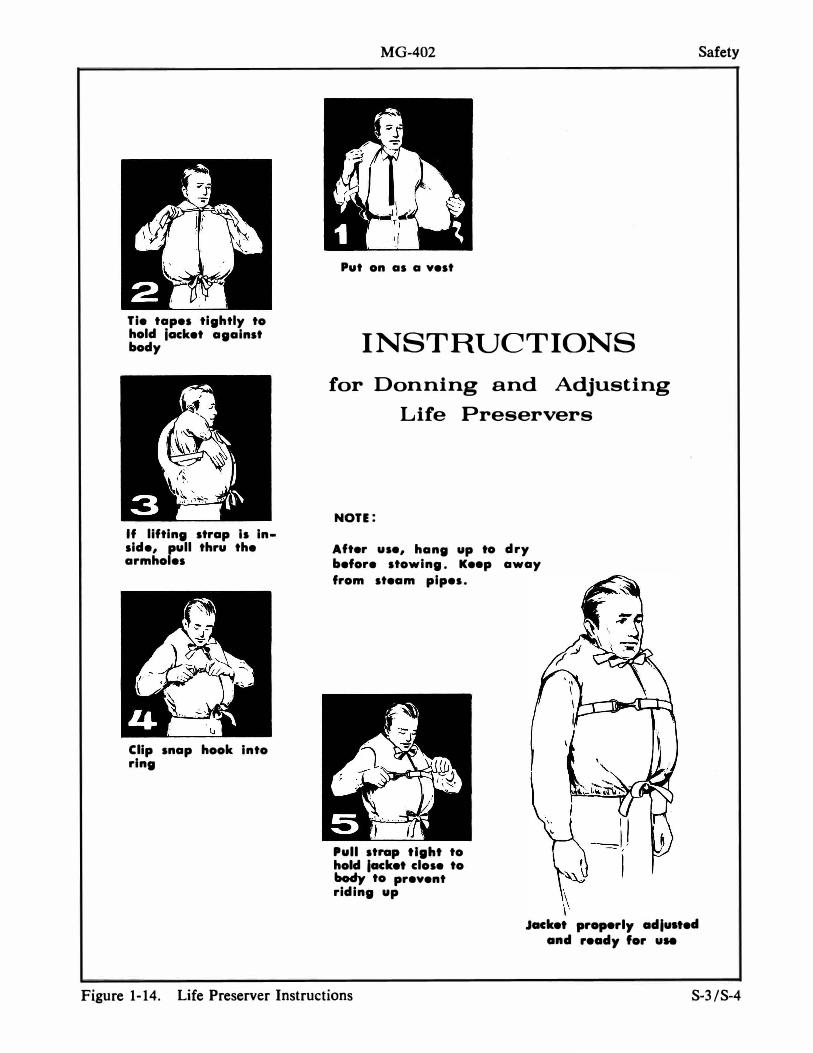
Tie tapes tightly to hold locket against body
If lifting strap Is Inside, pull thru the armholes
Clip snap hook Into ring
MG-402
Put on as a vest
INSTRUCTIONS
for Donning and Adjusting
Life Preservers
NOTE:
After use, hang up to dry before stowing. Keep away
from steam pipes.
Pull strap tight to hold lacket close to body to prevent riding up
, ��
�, Jacket properly adlustecl
and ready for use
Safety
Figure 1-14. Life Preserver Instructions S-3/S-4

MG-402 Section II
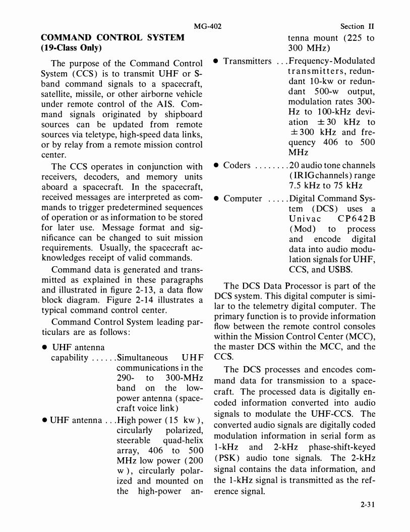
tenna mount ( 225 to 300 MHz )
COMMAND CONTROL SYSTEM (19-Class Only)
The purpose of the Command Control System ( CCS ) is to transmit UHF or Sband command signals to a spacecraft, satellite, missile, or other airborne vehicle under remote control of the AIS. Command signals originated by shipboard sources can be updated from remote sources via teletype, high-speed data links, or by relay from a remote mission control center.
The CCS operates in conjunction with receivers, decoders, and memory units aboard a spacecraft. In the spacecraft, received messages are interpreted as commands to trigger predetermined sequences of operation or as information to be stored for later use. Message format and significance can be changed to suit mission requirements. Usually, the spacecraft acknowledges receipt of valid commands.
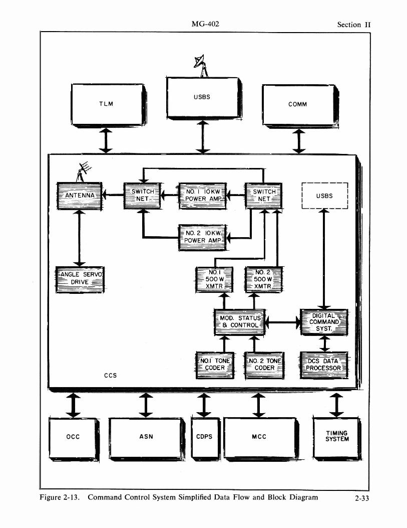
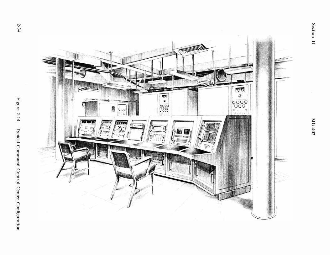
Command data is generated and transmitted as explained in these paragraphs and illustrated in figure 2- 1 3 , a data flow block diagram. Figure 2- 1 4 illustrates a typical command control center.
Command Control System leading particulars are as follows :
• UHF antenna capability . . . . . . Simultaneous U H F
communications i n the 290- to 3 00-MHz band on the lowpower antenna ( spacecraft voice link )
• UHF antenna . . . High power ( 1 5 kw ) , circularly polarized, steerable quad-helix array, 406 to 500 MHz low power ( 200 w ) , circularly polarized and mounted on the high-power an-
• Transmitters . . . Frequency - Modulated t r a n s m i t t e r s , redundant 1 0-kw or redundant 5 00-w output, modulation rates 300-Hz to 1 00-kHz deviation ± 30 kHz to ± 3 00 kHz and fre-
quency 406 to 500 MHz
• Coders . . . . . . . . 20 audio tone channels ( IRI G channels ) range 7 . 5 kHz to 75 kHz
• Computer . . . . . Digital Command System ( DCS ) uses a U n i v a c C P 6 4 2 B ( Mod ) to process and encode digital data into audio modul ation signals for UHF, CCS, and USBS.
The DCS Data Processor is part of the DCS system. This digital computer is similar to the telemetry digital computer. The primary function is to provide information flow between the remote control consoles within the Mission Control Center (MCC), the master DCS within the MCC, and the CCS.
The DCS processes and encodes command data for transmission to a spacecraft. The processed data is digitally encoded information converted into audio signals to modulate the UHF-CCS. The converted audio signals are digitally coded modulation information in serial form as I-kHz and 2-kHz phase-shift-keyed ( PSK ) audio tone signals. The 2-kHz signal contains the data information, and the I-kHz signal is transmitted as the reference signal.
2-31
Section II M G-402
The DCS can also receive ( via telemetry PCM link ) , monitor, and validate the command data transmitted by the CCS.
The same processed audio signals which modulate the UHF Command Control System are also used to modulate the USBS command control section .
Audio tone coders have also been included in the CCS for general Range use. These coders generate 20 standard IRIG ( Inter-Rartge Instrumentation Group ) audio tone frequencies between 7S00 and 7S ,000 Hz. The coders can generate and mix as many as six audio tone channels concurrently.
The Modulation Status and Control Panel provides the ability to select outputs from any of the available coders for application to either of the transmitter/ exciters.
The SOO-watt transmitter/exciters generate Command Control carrier frequencies at O .S-MHz intervals from 406 to SOO MHz. There is a modulator in the transmitter / exciter which modulates the generated carrier with the command data received from the Modulation Status and Control Panel. When used as a transmitter, the system can directly transmit the command signal through the antenna at a power level up to SOO watts . Through the use of a power dividing network and heat exchanger system, the system can be used as an exciter to supply 10 to 3S watts of power to the power amplifiers for am'plification to 1 0 kw.
2-32
This switching network permits selection of the transmitter/exciter to be used with either of the power amplifiers, transmission of the transmitter/exciter output directly to the antenna, or termination of the transmitter/exciter output into a dummy load. This network also permits automatic switch over between the transmitter / exciters in the event of failure of the system which had been selected as the master system .
The 1 0-kw power amplifiers provide amplification of the 10- to 3S-watt command signal received from the transmitter/exciter to a power level up to 1 0 kw.
This portion of the switching network provides selection of the power amplifier to be used as the master system and power amplifier used as the standby system. Automatic switchover capability from the master system to the standby system is provided if the master system fails .
The antenna array is a quad-helix array with a gain of -1 8 db and a beamwidth of 20 degrees.
Antenna elements are also provided to transmit UHF voice communications ( 290 to 300 MHz ) to and from the spacecraft.
The array is mounted on a steerable pedestal. Synchro slaving signals are received from the Acquisition and Stabilization Network, or the pedestal can be steered manually from the console in the Command Control Room.
MG-402 Section II
USBS TLM
ees
oee ASN COPS Mee
eOMM
r-----, I I I USBS : L_ __---1
TI MING SYSTE M
Figure 2-13. Command Control System Simplified Data Flow and Block Diagram 2-33
Se
ction
II
2-34
�·go::: �
& �
g . .:J
_�
_
t o_
o- : -
II \
MG
-402
�
.�-.-)
Figu
re 2-14_ T
ypical C
om
man
d C
on
trol C
enter C
on
figu
ration

MG-402 Section II
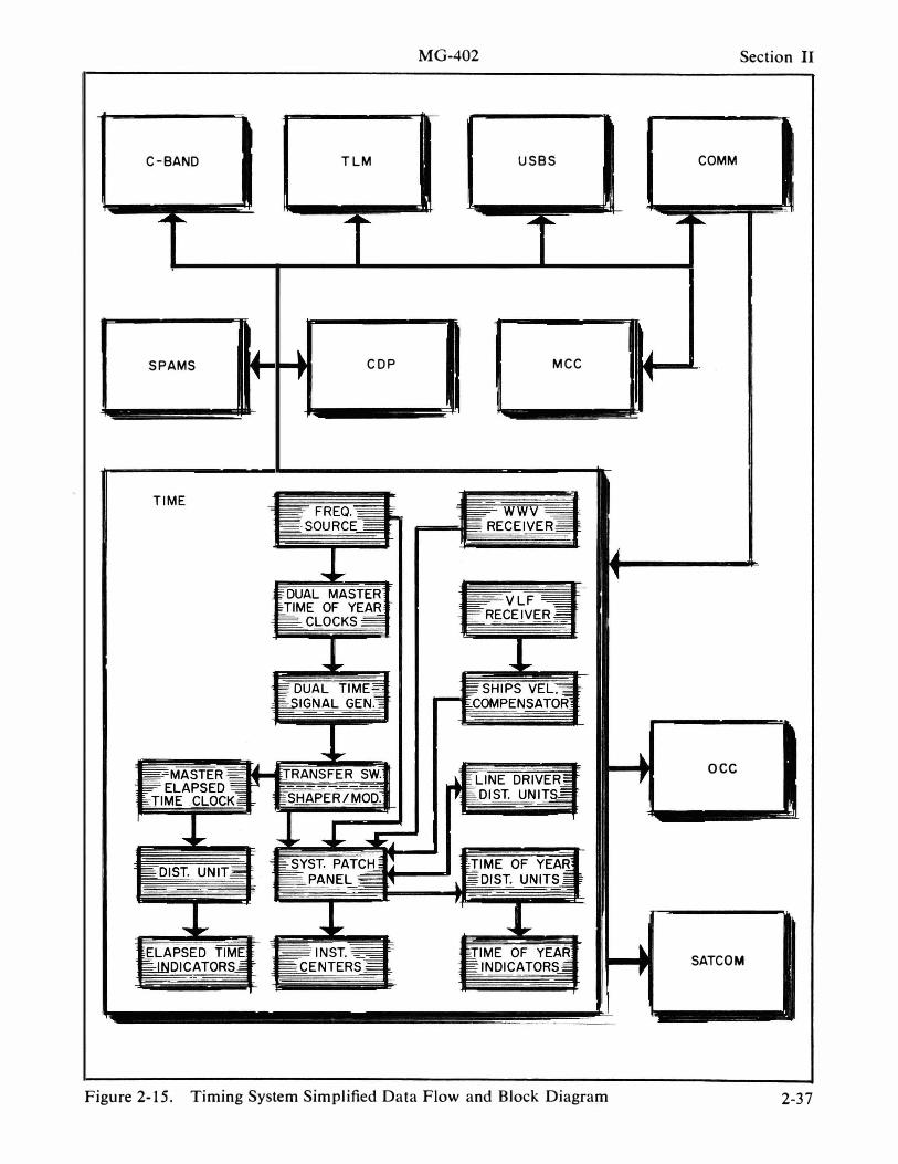
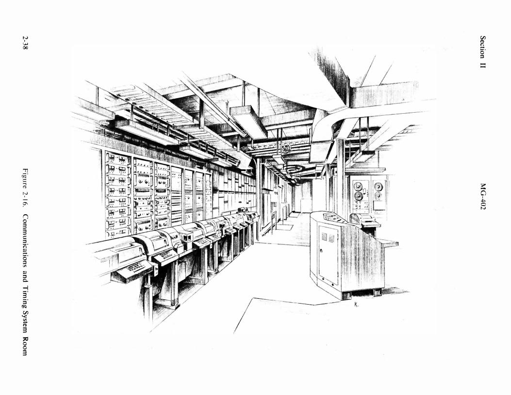
TIMING SYSTEM
The timing system generates and distributes standard frequencies, time codes, and repetition rates for use by shipborne instrumentation. How this is accomplished is illustrated by the timing system data flow and block diagram, figure 2- 1 5 . Figure 2- 1 6 illustrates the communications and timing center room.
Timing System leading particulars are as follows :
• Standard reference frequencies
• Rubidium frequency
. . 5 MHz, 1 MHz, and 1 00 kHz; pulses-2 pps, 20 pps, 400 pps, 2 ppm, and 1 0 ppm ; and time signals -BCD time-of -year to 0 . 1 sec, serial binary timeof-year to 0 . 1 sec time codes IRIG A-E, NASA 1 / sec, 1 / min, l /hr and serial decimal ; all b ased on rubidium standard. S y n c h r o n i z at i o n with WWV s t a n d a r d - t i m e broadcasts . Standard f r e q u e n c i e s , pulses, and time signals distributed to instrumen-tation centers .
standard . . . . long term stability, 5 parts in 1 01 1 per year short term stability, 1 part in 1 0 1 1 per second
• Crystal oscillator . . . . long term stability 1 part
in 1 010 per day short term stability 1 part in 1 010 per second
The WWV receiver receives standard time broadcasts on HF from the National
Bureau of Standards at Boulder, Colorado. Outputs from this receiver are time-of-day in voice and synchronization pulses from which the master time-of -year clock is synchronized.
The VLF receiver receives standard frequency broadcasts in the 1 0- to 30-kHz frequency range . Outputs from this receiver show the phase relationship between the received signal and the reference frequencies from the local fre-quency source.
The Ship's Velocity Compensator eliminates doppler effect on the VLF receivedsignal when the ship is underway. Inputs are VLF standard receiver outputs, ship's velocity, heading, and position . The output from this unit indicates the true phase relationships between the VLF signal and system reference source with the doppler effect removed.
Frequency Source-Standard reference frequencies are generated with a rubidium standard and a crystal oscillator. The primary rubidium standard has a long-term stability of 5 parts in 1 01 1 per year, and the secondary crystal oscillator has a long-term stability of 1 part in 1 01 0 per day. The Frequency Source generates and distributes 5-MHz, I -MHz, and 1 00 kHz frequencies .
Master Time-of -Year Clocks contain six-decade frequency dividers and a digital clock. These generate repetition rates and derive time-of-year information in seconds, minutes, hours, and days . Input i s a I -MHz frequency from the frequency source. Outputs are the generated signals explained previously. This unit contains the necessary output drivers for signal distribution.
The Time Signal Generator accepts the outputs of the Master Time-of-Year Clock and generates standard time codes and frequencies not available as standard outputs
2-3 5
Section II MG-402
from the Master Time-of-Year Clock. output signals . All inputs and outputs Outputs from this unit include the follow- associated with this unit are patched from ing time code formats : IRIG A, IRIG B, and returned to the patch panel. {RIG C, IRIG D, IRIG E, NASA l lsec, The patch panel is a removable proNASA Ilmin, NASA I lhr, NASA Serial gramable board. Three boards are proDecimal , Serial Binary Time-of -Year vided to satisfy different support require( seconds ) , Serial Binary Time-of-Year ments. Outputs from the patch panel are ( tenths of seconds ) , Serial Binary Time- directed to instrumentation centers. of-Day ( seconds ) , 40 pps, 20 pps, 2 pps, The Time-of-Year Distribution Unit 2 ppm, and 1 0 ppm repetition rates. accepts BCD parallel time-of-year from
Shaper Modulator Unit I Transfer the Master Time-of-Year Clocks via the Switch-The Transfer Switch allows tim- transfer switch. This unit consists of tering signals from either of the time signal minal blocks, indicator drivers, and the generators and Master Time-of-Year timing distribution frame. The BCD sigClocks to be distributed. The shaper nals, once amplified, drive the Time-ofmodulator unit contains shapers ( filters ) Year Indicators. to convert shifting logic levels to sinusoids, Elapsed Time Generator, Distribution modulators to modulate carrier frequen- and Display-the Master Elapsed Time cies with NASA and IRIG time codes, and Clock accepts the parallel BCD time-ofpulse shapers to generate pulses from year, 1 00,000 pps, and 1 pps from the transitions of the shifting logic levels. Out- Master Time-of-Year Clock via the transputs of this unit go to the patch panel . fer switch . Elapsed time is derived from
The Line Driver Distribution Unit pro- these inputs and is distributed to elapsed vides isolation, amplification, and im- time indicators in the instrumentation pedance matching for the timing system rooms.
2-3 6
MG-402
C-BANO TLM USBS
SPAMS COP MCC
Figure 2-15. Timing System Simplified Data Flow and Block Diagram
Section II
COMM
oce
SATCOM
2-37
Sec
tion
II
MG
-40
2
� ,
2-3
8
Fig
ure
2-1
6.
Co
mm
un
ica
tion
s a
nd
T
imin
g S
ystem
R
oo
m

M G-402 Section II
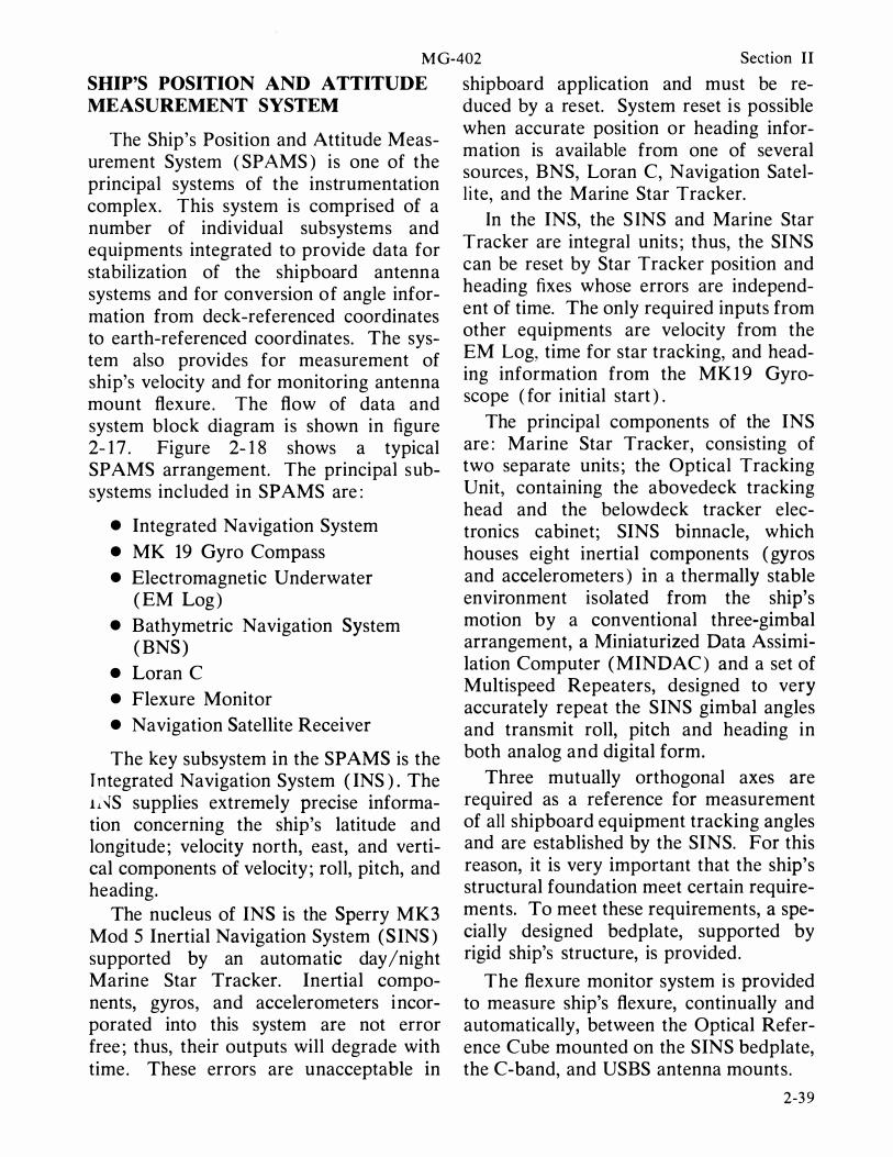
SHIP'S POSITION AND ATTITUDE shipboard application and must be re-MEASUREMENT SYSTEM duced by a reset. System reset is possible
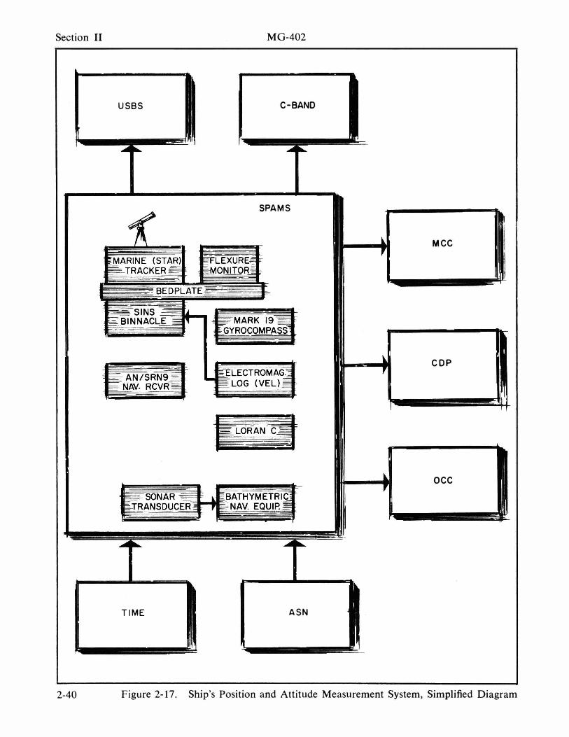
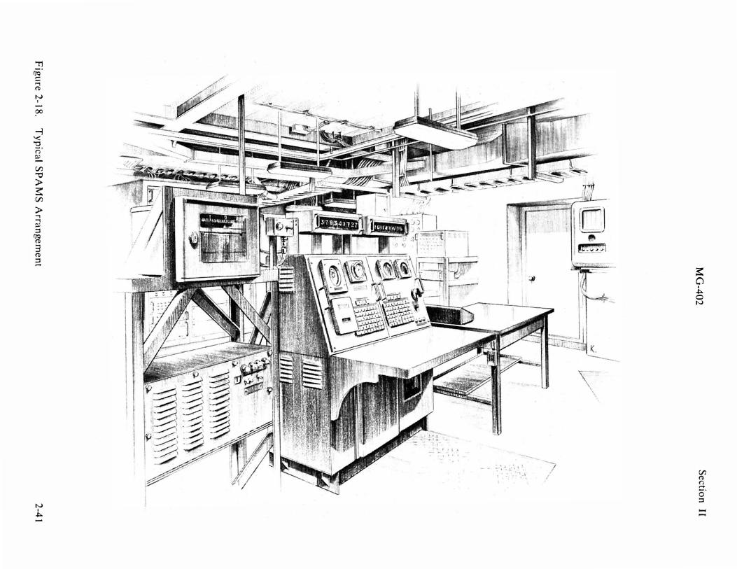
The Ship's Position and Attitude Measurement System ( SPAMS ) is one of the principal systems of the instrumentation complex. This system is comprised of a number of individual subsystems and equipments integrated to provide data for stabilization of the shipboard antenna systems and for conversion of angle information from deck-referenced coordinates to earth-referenced coordinates. The system also provides for measurement of ship's velocity and for monitoring antenna mount flexure . The flow of data and system block diagram is shown in figure 2- 1 7 . Figure 2- 1 8 shows a typical SP AMS arrangement. The principal subsystems included in SP AMS are :
• Integrated Navigation System
• MK 19 Gyro Compass
• Electromagnetic Underwater ( EM Log )
• Bathymetric Navigation System ( BNS )
• Loran C
• Flexure Monitor
• Navigation Satellite Receiver
The key subsystem in the SP AMS is the r ntegrated Navigation System ( INS ) . The 11'\lS supplies extremely precise information concerning the ship's latitude and longitude ; velocity north, east, and vertical components of velocity ; roll, pitch, and heading.
The nucleus of INS is the Sperry MK3 Mod 5 Inertial Navigation System (SINS ) supported by an automatic day /night Marine Star Tracker. Inertial components, gyros, and accelerometers incorporated into this system are not error free ; thus, their outputs will degrade with time. These errors are unacceptable in
when accurate position or heading information is available from one of several sources, BNS, Loran C, Navigation Satell ite, and the Marine Star Tracker.
In the INS, the S INS and Marine Star Tracker are integral units ; thus, the SINS can be reset by Star Tracker position and heading fixes whose errors are independent of time. The only required inputs from other equipments are velocity from the EM Log, time for star tracking, and heading information from the MK 1 9 Gyroscope ( for initial start ) .
The principal components of the INS are : Marine Star Tracker, consisting of two separate units ; the Optical Tracking Unit, containing the abovedeck tracking head and the below deck tracker electronics cabinet; SINS binnacle, which houses eight inertial components ( gyros and accelerometers ) in a thermally stable environment isolated from the ship's motion by a conventional three-gimbal arrangement, a Miniaturized Data Assimilation Computer ( MINDAC ) and a set of Multispeed Repeaters, designed to very accurately repeat the SINS gimbal angles and transmit roll, pitch and heading in both analog and digital form.
Three mutually orthogonal axes are required as a reference for measurement of all shipboard equipment tracking angles and are established by the SINS. For this reason, it is very important that the ship's structural foundation meet certain requirements. To meet these requirements, a specially designed bedplate, supported by rigid ship's structure, is provided.
The flexure monitor system is provided to measure ship's flexure, continually and automatically, between the Optical Reference Cube mounted on the SINS bedplate, the C-band, and USBS antenna mounts.
2-3 9
Section II MG-402
USBS C-BANO
SPAMS
MCC
COP
OCC
TIME ASN
2-40 Figure 2-17. Ship's Position and Attitude Measurement System, Simplified Diagram
Fig
ure
2-18
. T
yp
ica
l SP
AM
S A
rran
ge
me
nt M
G-4
02
S
ec
tion
II
2-4
1
Section II MG-402
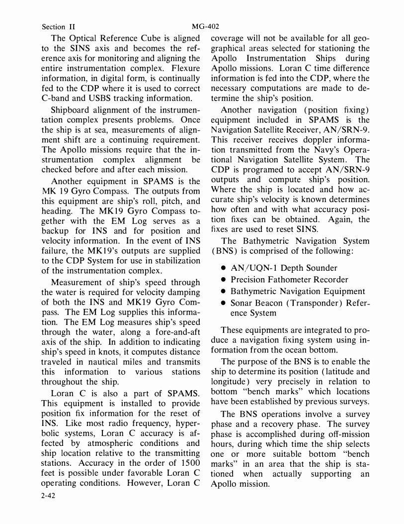
The Optical Reference Cube is aligned to the SINS axis and becomes the reference axis for monitoring and aligning the entire instrumentation complex. Flexure information, in digital form, is continually fed to the CDP where it is used to correct C-band and USBS tracking information.
Shipboard alignment of the instrumentation complex presents problems. Once the ship is at sea, measurements of alignment shift are a continuing requirement. The Apollo missions require that the instrumentation complex alignment be checked before and after each mission.
Another equipment in SP AMS is the MK 1 9 Gyro Compass. The outputs from this equipment are ship's roll , pitch, and heading. The MK 1 9 Gyro Compass together with the EM Log serves as a backup for INS and for position and velocity information. In the event of INS failure, the MK 1 9's outputs are supplied to the CDP System for use in stabilization of the instrumentation complex .
Measurement of ship's speed through the water is required for velocity damping of both the INS and MK 1 9 Gyro Compass. The EM Log supplies this information. The EM Log measures ship's speed through the water, along a fore-and-aft axis of the ship. In addition to indicating ship's speed in knots, it computes distance traveled in nautical miles and transmits this information to vanous stations throughout the ship.
Loran C is also a part of SP AMS. This equipment is installed to provide position fix information for the reset of INS. Like most radio frequency, hyperbolic systems, Loran C accuracy is affected by atmospheric conditions and ship location relative to the transmitting stations. Accuracy in the order of 1 5 00 feet is possible under favorable Loran C operating conditions. However, Loran C
2-42
coverage will not be available for all geographical areas selected for stationing the Apollo Instrumentation Ships during Apollo missions. Loran C time difference information is fed into the CDP, where the necessary computations are made to determine the ship's position.
Another navigation ( position fixing ) equipment included in SPAMS is the Navigation Satellite Receiver, AN/SRN-9 . This receiver receives doppler information transmitted from the Navy's Operational Navigation Satellite System . The CDP is programed to accept AN/SRN-9 outputs and compute ship's position. Where the ship is located and how accurate ship's velocity is known determines how often and with what accuracy position fixes can be obtained. Again, the fixes are used to reset SINS.
The Bathymetric Navigation System ( BNS ) is comprised of the following :
• AN/UQN- 1 Depth Sounder
• Precision Fathometer Recorder
• Bathymetric Navigation Equipment
• Sonar Beacon ( Transponder ) Reference System
These equipments are integrated to produce a navigation fixing system using information from the ocean bottom.
The purpose of the BNS is to enable the ship to determine its position ( latitude and longitude ) very precisely in relation to bottom "bench marks" which locations have been established by previous surveys .
The BNS operations involve a survey phase and a recovery phase . The survey phase is accomplished during off-mission hours, during which time the ship selects one or more suitable bottom "bench marks" in an area that the ship is stationed when actually supporting an Apollo mission.
MG-402 Section II
Selection of a site is based on two across the two diagonals of the area being qualifications : water depth must be in the examined. 200- to 4000-fathom range, and bottom After site selection, three transponders topography across the site must display are launched and moored to the ocean botan rms depth variation of at least 1 2 tom for use in obtaining precise knowlfathoms, with a normalized spectral edge of the ship's ground track during the density having an effective bandwidth of survey operation. This enables a surface one cycle/mile minimum. Site adequacy ship to determine its relative position is determined by taking depth profiles to an accuracy of better than 1 00 feet.
2-43 / 2-44

MG-402 Section II
ACQUISITION AND STABILIZATION NETWORK
The Acquisition and Stabilization Network ( ASN ) provides target acquisition and antenna stabilization signals required to interconnect, position, and stabilize the tracking and remotely controlled directional antennas on the ship. The system may be controlled centrally from the Operations Control Center or locally at the individual antenna consoles. The prime designation source may be either the CDP Computer, C-band Antenna, Optical Director, TM- l Antenna, or the USB Antenna. Any or all of the remaining antennas, including the TM-2 Telemetry Antenna and the Command Control Antenna, may then be slaved to the prime designation source for acquisition purposes. The Star Tracker may also be slaved to the prime designation source .
In general, initial acquisition is accomplished in either of two ways. Designation data are stabilized deck coordinates generated in the CDP and transmitted via the Acquisition Subnetwork to the selected antennas. The alternate mode of operation is to manually order antenna position from hand wheels at one of the individual antenna control areas. These data are transmitted to the computer, stabilized, then transmitted back to selected antennas via the Stabilization Subnetwork. When lock-on is accomplished and automatic tracking begins, on-track signals are transmitted to the pertinent consoles via the On-Track Subnetwork. The designate controller in the OCC receives the on-track data from the designate sources and assigns the master antenna for the acquisition and tracking bus.
The system has an optical acquisition aid and four principal subnetworks : Ship's Heading, On-Track, Stabilization, and Ac-
quisltlOn Subnetworks. These functions are described in the following paragraphs . Figure 2- 1 9 is a composite data flow and block diagram of the system. Figure 2-20 illustrates a typical ASN room.
Acquisition-Stabilization leading particulars are as follows :
• Antenna designation control and distribution
• Manually ordered antenna position stabilization
• Distribution of on-track signals of active trackers to all tracking elements
• Distribution of ship's heading • Optical director designation
• Acquisition and Stabilization
Network . . . . . . . . . 0 .5 degree overall a c c u r a c y u n d e r maximum dynamic loads
• Optical Director . , acquisition aid for balloon and aircraft
• Antenna Control Panels . . . . . . . . . . . tracking operator se
lection of designation
• Designate Control Console . . . . . . . . . . central selection of
master designation source
The Ship's Heading Subnetwork serves as a central distribution source for ship's heading indication. Ship's heading is obtained by selection in the Navigation Room of either INS or MK- 1 9 heading data and is distributed via the action cutout switchboard and synchro amplifiers to the following display units : antenna control panels, master acquisition and stabilization control panel, wheelhouse, Mission Control Center, Operations Control Center, and the Communication Transmitter Room.
2-45
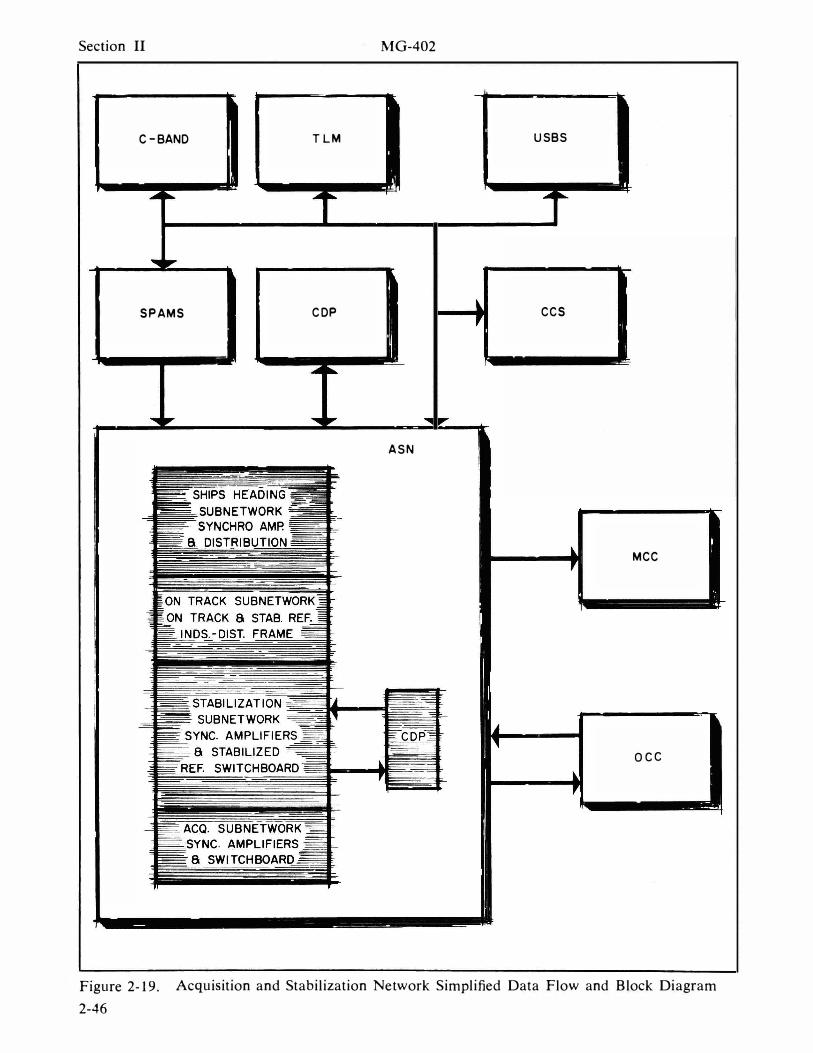
Section II MG-402
C-BANO TLM USBS
SPAMS COP CCS
ASN
MCC
acc
Figure 2-19. Acquisition and Stabilization Network Simplified Data Flow and Block Diagram
2-46
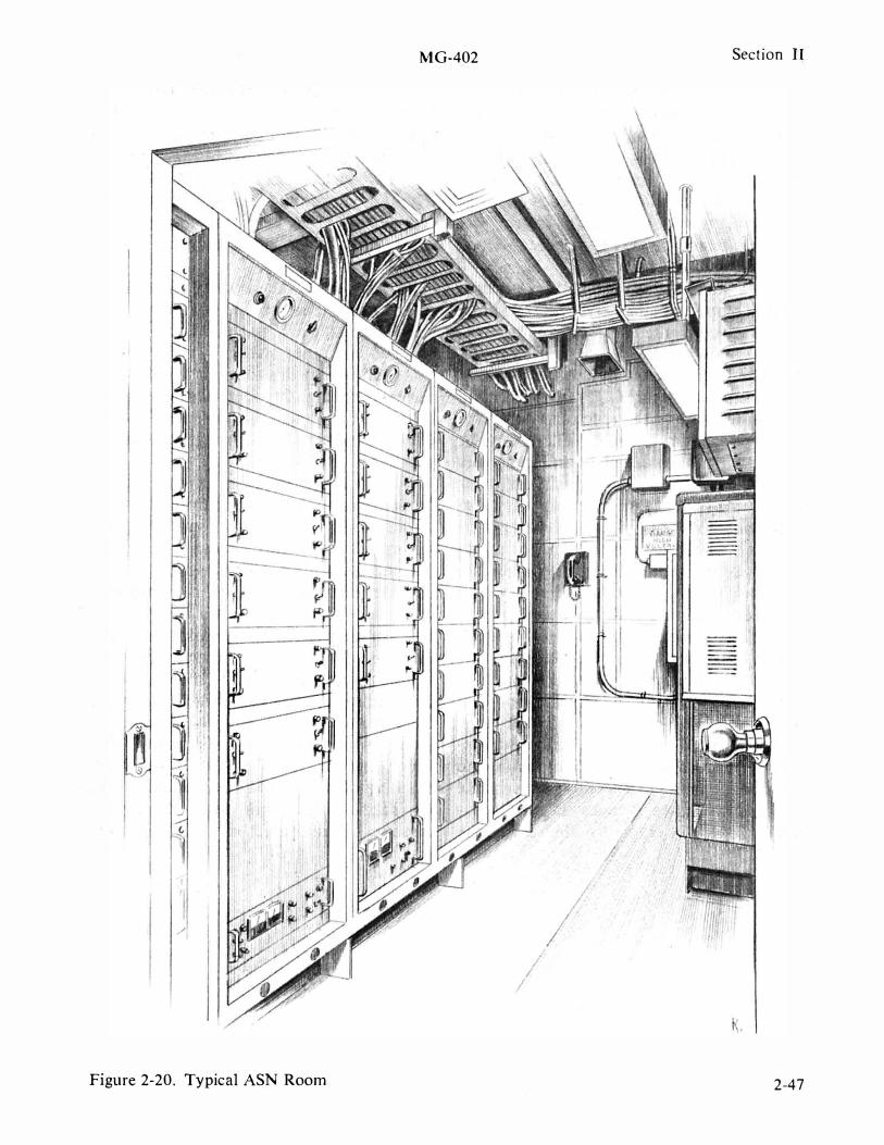
MG-402
Figure 2-20. Typical ASN Room
/ I
Section II
I
2-47
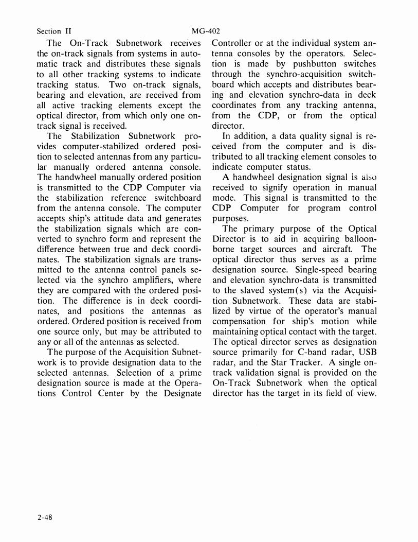
Sect ion II MG-402
The On-Track Subnetwork receIves the on-track signals from systems in automatic track and distributes these s ignals to all other tracking systems to indicate tracking status. Two on-track signals, bearing and elevation, are received from all active tracking elements except the optical dire<;:tor, from which only one ontrack signal is received.
The Stabilization Subnetwork provides computer-stabilized ordered position to selected antennas from any particular manual ly ordered antenna console. The handwheel manually ordered position is transmitted to the CDP Computer via the stabilization reference switchboard from the antenna console . The computer accepts ship's attitude data and generates the stabilization signals which are converted to synchro form and represent the difference between true and deck coordinates. The stabilization signals are transmitted to the antenna control panels selected via the synchro amplifiers, where they are compared with the ordered position. The difference is in deck coordinates, and positions the antennas as ordered. Ordered position is received from one source only, but may be attributed to any or all of the antennas as selected.
The purpose of the Acquisition Subnetwork is to provide designation data to the selected antennas. Selection of a prime designation source is made at the Operations Control Center by the Designate
2-48
Controller or at the individual system antenna consoles by the operators. Selection is made by pushbutton switches through the synchro-acquisition switchboard which accepts and distributes bearing and elevation synchro-data in deck coordinates from any tracking antenna, from the CDP, or from the optical director.
In addition, a data quality signal is received from the computer and is distributed to all tracking element consoles to indicate computer status.
A handwheel designation signal is also received to signify operation in manual mode. This signal is transmitted to the CDP Computer for program control purposes.
The primary purpose of the Optical Director is to aid in acquiring balloonborne target sources and aircraft. The optical director thus serves as a prime designation source. Single-speed bearing and elevation synchro-data is transmitted to the slaved system ( s ) via the Acquisition Subnetwork. These data are stabilized by virtue of the operator's manual compensation for ship's motion while maintaining optical contact with the target . The optical director serves as designation source primarily for C-band radar, USB radar, and the Star Tracker. A single ontrack validation signal is provided on the On-Track Subnetwork when the optical director has the target in its field of view.

MG-402 Section II
OPERATIONS CONTROL CENTER monitor and control the ship to support
The Operations Control Center ( OCC ) provides centralized control and coordination of all onboard instrumentation systems. It also provides single-point control reporting into and coordinating with the National Range Network. This control center is used by the SOM, assisted by the Ship's Instrumentation Manager ( SI�1 ) and the Designate Controller, to direct and control the ship's instrumentation. Figure 2-2 1 illustrates the data flow and block diagram. Figures 2-22 and 2-23 illustrate the OCC aboard both classes of ships .
Operations Control Center leading particulars are as follows :
• Single-point contact with the National Range Network
• Centralized control and coordination of all shipboard instrumentation systems for National Range programs
• Trajectory data display - plotting boards and height recorders
• The SOM has communication and display capabilities to monitor and control the ship and to deport and coordinate with the National Range Network .
• The SIM monitors and controls the ship's instrumentation complex .
• The Designate Controller supports the SIM by assigning source data and antennas for acquisition and tracking phase of mission .
The master systems console is manned by both the SOM and the SIM. The SOM position has communication and display capabilities which enable him to
Range missions . During Apollo missions, the SOM mans the M&O console in the MCC. An alternate mans the SOM console . The console provides for bilateral information transmISSIon with four sources : The National Range Network, the bridge, the Maintenance and Operations Supervisor ( M&O ) in the shipboard Mission Control Center, and the shipboard instrumentation complex . The SIM position has communication and display capabilities which enable him to monitor and control the shipboard instrumentation complex. The SIM can exchange information with the SOM, Designate Controller, MCC, M&O, and each instrumentation system.
The designate control console is manned by the Designate Controller, who assigns the source and appropriate antenna or antennas for the acquisition phase of the ship's mission as directed by the instrumentation plan of the mission. The Designate Controller has information on the quality of the data obtained from the designate sources. Information is exchanged between the designate console and the instrumentation systems, the SIM console, and the M&O Console in the MCC.
The Trajectory Plotting Boards in the OCC consist of two 30- by 30-inch plotting boards and one height recorder. These units display the target's present position in Cartesian coordinates along the surface of the earth as determined by the computer from the radar data or orbital parameters .
2-49
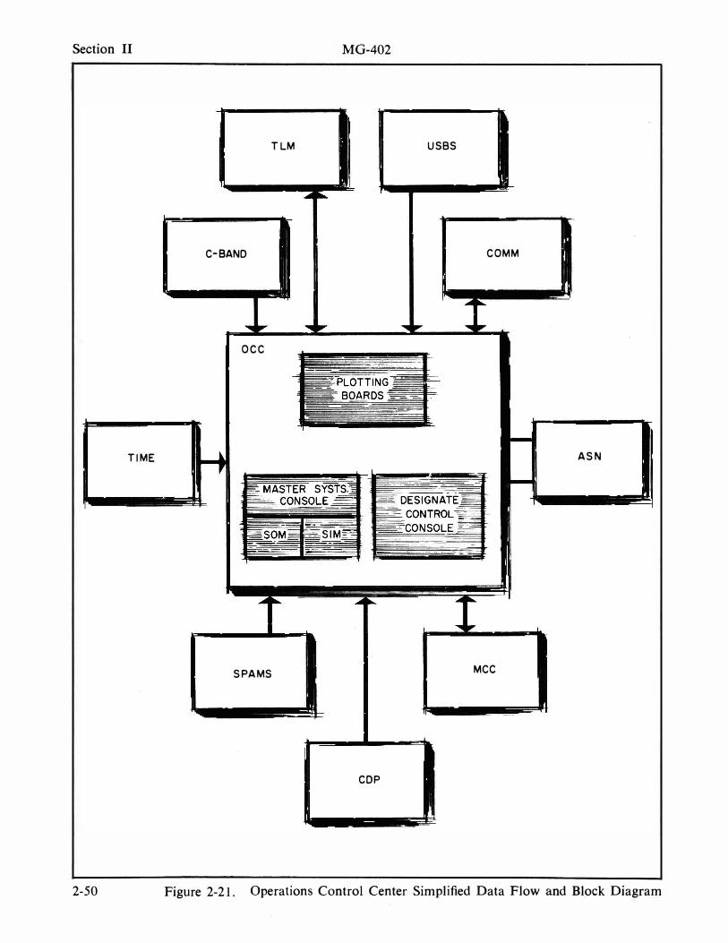
Section II
TIME
2-50
MG-402
TLM USBS
C-BANO COMM
OCC
ASN
- --- --- --�- --=
SPAMS MCC
COP
Figure 2-21. Operations Control Center Simplified Data Flow and Block Diagram
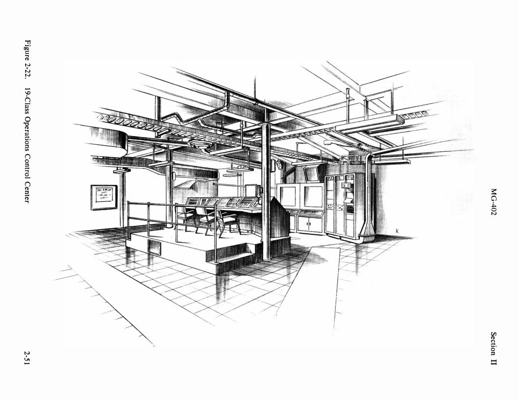
MG
-40
2
Fig
ure
2-2
2.
19-C
lass O
pe
ratio
ns C
on
trol C
en
ter
1\
Se
ction
I
I
2-5
1
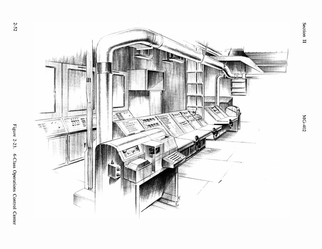
Sec
tion
II
2-5
2
MG
-40
2
I I I I '1
"
I ""-
I
1 "',-
"
Fig
ure
2-2
3.
6-C
Jass O
pera
tion
s C
on
trol
Cen
ter

MG-402 Section II
tion of cutoff conditions and flight commitment
MISSION CONTROL CENTER (19-Class Only)
The Mission Control Center ( MCC ) is the centralized control facility from which NASA Flight Control personnel monitor the shipboard instrumentation status and the APOLLO spacecraft data and communicate with the NASA Network and spacecraft. Figure 2-24 depicts the data flow and system block diagram. Figure 2-25 shows the Mission Control Center.
The MCC leading particulars are as follows : Apollo Mission Monitoring contains consoles, displays, communications, and instrumentation for NASA Flight Controllers .
Consoles • Command
Communicator . . determines status of
• Vehicle
spacecraft and astron auts by communication with spacecraft and vehicle, flight dynamic, and aeromedical monitors, forwards data to network
Monitors ( 4 ) . . . two command service
• Aeromedical
modules, one S-IVB/ LEM and one LEM monitor - displays : CRT's, pen recorder, and teletype
Monitor . . . . . . . displays : CRT's, pen recorder, and cardioscope for monitoring astronauts' and lifesupport functions
• Flight Dynamics Officer . . . . . . . . monitors insertion and
injection trajectories for emergency evalua-
• Maintenance and Operation . . monitors shipboard in
strumentation s t a t u s and displays instrumentation status on flight control consoles
The Command Communicator has the responsibility of determining the status of the spacecraft and the astronauts by means of direct communications with the spacecraft and by reports from the vehicle monitor and aeromedical members of his flight control team. He reports this status to the network and receives his instructions from the network. In event of failure of the data and communication links to the network, the Command Communicator has the responsibility for choosing and initiating the spacecraft commands necessary for the success of the mission and the well-being of the astronauts.
Four Flight Controllers man the vehicle monitor subsystem, comprised of two command services module consoles, one S-IVB/LEM console, and one lunar excursion module system monitor console. The Flight Controllers have the responsibility of monitoring the status of the spacecraft instrumentation and reporting this status to the Command Communicator. Spacecraft data is selected from the telemetry signals and printed by a highspeed printer. Other displays include event-indicating lights and a vertical pen recorder. They have the capability to take direct action concerning the spacecraft instrumention in event of data and communications link failure to the network.
2-53
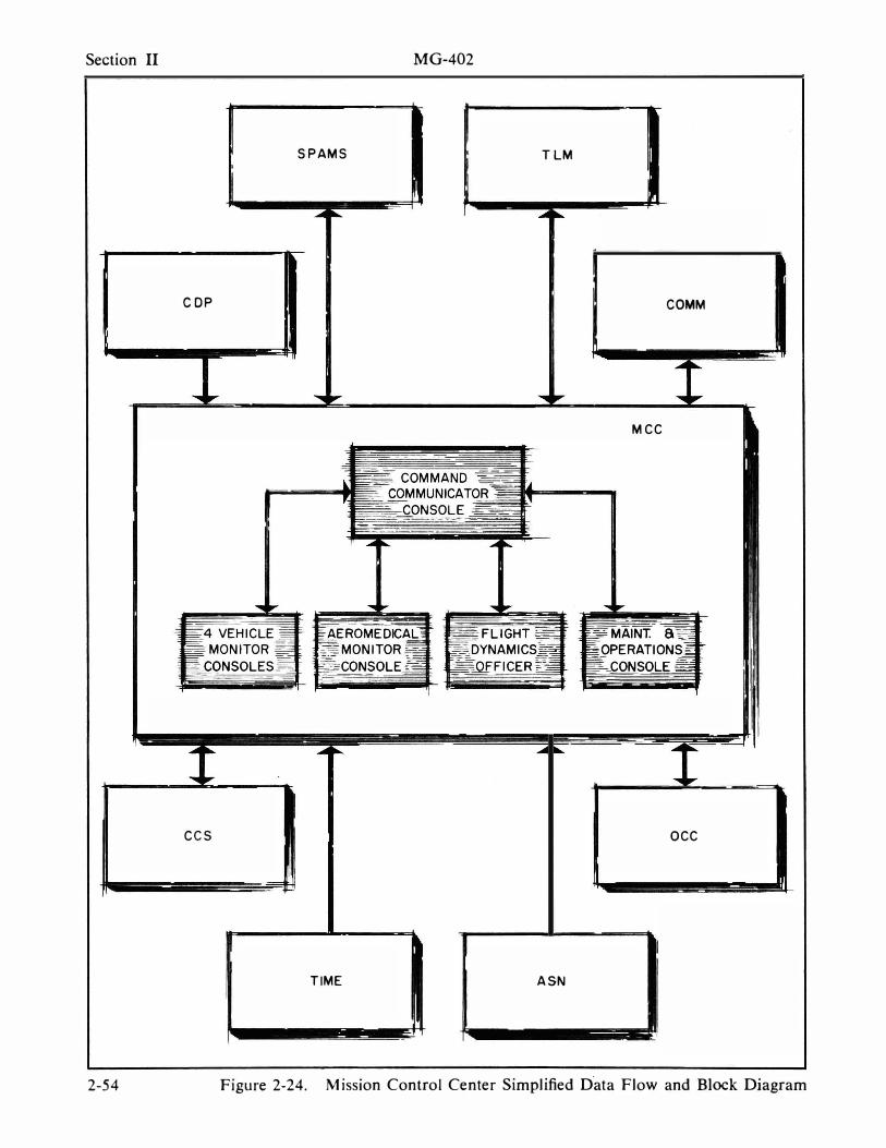
Section II
COP
ecs
2-54
MG-402
SPAMS TLM
COMM
Mee
oee
TIME ASN
Figure 2-24. Mission Control Center Simplified D"ata Flow and Block Diagram
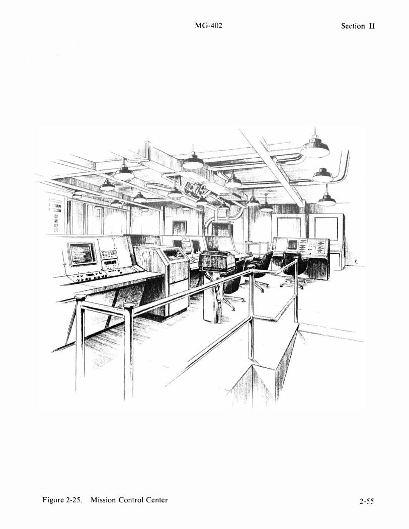
Figure 2-25. Mission Control Center
MG-402 Section II
K
2-55
Section II MG-402
The aeromedical monitor console is manned by a medical team which monitors the performance of the astronauts and the operation of the life support systems and reports of the Command Communicators . The monitoring is accomplished by observing electrocardiograms, a display module, event indicators, and a pen recorder.
The Flight Dynamics Officer ( FDO ) is responsible for monitoring" during powered flight, the insertion and injection trajectory of the Apollo spacecraft from the standpoint of crew safety and mission success. The FDO evaluates the cutoff conditions and commits the flight as a "go" or a "no go." The FDO function is
2-56
normally accomplished only in the I ntegrated Mission Control Center ( IMCC ) , Houston, Texas. However, during periods of interrupted communications or severely degraded performance, the shipboard FDO assumes this responsibility.
The Maintenance and Operations ( M&O ) Supervisor monitors the status of the shipboard instrumentation systems and displays this status on the flight controller's consoles . He requires communications with the flight controllers, the Ship's Operation Manager's ( SOM ) Console, the Ship's Instrumentation Manager ( S IM ) , the Designate Controller, and the ship's instrumentation systems.

M G-402 Section TI
SATELLITE COMMUNICATIONS TERMINAL (19-Class)
The Satellite Communications Terminal ( SATCOM ) is the primary communications system aboard the 1 9-Class for voice, tracking, and telemetry data to GSFC and MCC-H. Figure 2-26 is a composite data flow and system block diagram of the SATCOM Terminal. Each of the subsystems that comprises the SATCOM Terminal is briefly described in the following paragraphs .
ANTEN NA SUBSYSTEM
The antenna is a 30-foot parabolic antenna on a tracking mount. It has three axis characteristics : azimuth, elevation, and traverse ; therefore , it is capable of complete hemispherical coverage. The design is such that it automatically tracks a communications satellite from aboard ship and is controlled by : 1 ) a computer subsystem, or 2 ) antenna control console, or 3 ) remote-controlled position on the antenna mount, or 4 ) from the servo amplifier cabinet test panel. The antenna subsystem includes :
a . mount
b. feed
c. reflector
d. subreflector
e. RF transmission lines to the transmit and receive subsystems
f. servo drives
g. reference stable element
RECEIVE SUBSYSTEM
The receiver is capable of simultaneous reception and demodulation of any two communications frequencies in a 1 50-MHz band and anywhere within the frequency range of 3 .700 GHz to 4. 200 GHz.
A tracking receiver within the receive subsystem automatically searches a frequency spectrum, locates and locks on to the instantaneous frequency of the selected satellite beacon, and tracks the satellite frequency. In addition, the tracking receiver extracts tracking error signals which arise from an offset of the electrical axis of the antenna system in respect to the arrival of beacon signals from the true RF axis of the satellite.
The receive subsystem consists of the fol lowing :
a. low noise amplifiers
b. receiver translators
c. communication demodulators
d. tracking receiver and demodulator
T RANSMIT SUBSYSTEM
Transmitter operation is in any frequency in the band of 5 .925 to 6 .425 GHz. Power output is sufficient to deliver a maximum of 70 dbm into the transmit feed horn and is continuously adjustable down to 30 db below full power output.
The transmit subsystem is comprised of :
a . high power amplifiers
b. exciters
c. modulators
d. baseband equipment
e. protection and control circuits
f. heat exchangers
g. associated peripheral equipment
COMPUTER INTERFACE
The computer interface includes the equipment necessary to interface the Satell ite Communications ( SATCOM ) System with the existing CDP System. The computer is also used with the other tracking systems .
2-57
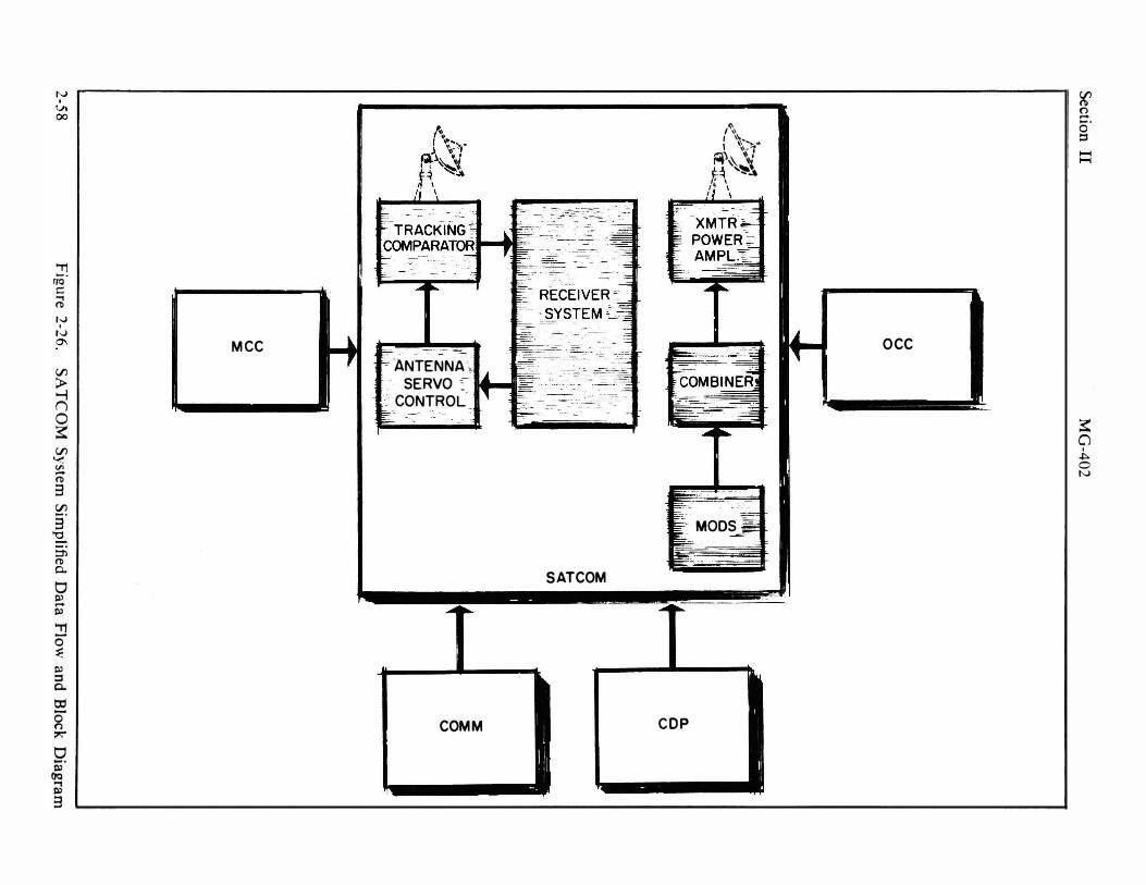
� r-----------------------�----------------------------------------------------------00
'TI rio' t:: ..., �
t-..) , N 0\ MCC
(/J :> """i n 0 � (/J V" Vi -� 3 � 3
'0 -. ::1l � 0..
0 tI' -til
'T1 0-� til ::s 0..
OJ
0-n �
9-til
OQ .., til 3
-- - -
---ANTENNA·� SERVO :
: CONTROL
COMM
- -�:-=---"'o-�:-�
SATCOM
(�, " '�'-�� '''1
�)� \� t:� ,� " \ ,� \ , \
--
.. � MODS ==
COP
OCC
W n -..... o .1:'
� CJ , """ o N
M G-402 Section II
The computer interface in conjunction of previously stored acqUisItIon paramewith the COP performs the following ters for the selected satellite and the functions : present position of the ship. The computer
a. Computes in real time the stabilized pointing angles required by the antenna subsystem to acquire and track on the satellite of interest
b. Computes in real time programed tracking angles required by the antenna subsystem for maintaining data tracking when the same cannot be accomplished actively
c. Computes line-of-sight information for the satellite of interest
d. Provides necessary buffering and signal conversion to guarantee signal compatibility at the computer subsystem interface with the antenna subsystem ( including the stable reference element) and the system time code generator
e. Computes other auxiliary functions within the limits of the subsystem which may be required or proof of interest in the operation of the system
COMP UTER SU BMO DES
The SA TCOM priority of computer operation is established at the computer input/output console . The computer, while in its internal standby mode, responds to the operator's SA TCOM submode selection. The SATCOM submode selection is not possible during computer internal acquisition or tracking modes . Provisions are made for the following submode operations :
Satellite Designate
This submode is for the purpose of acquisition . The computer calculates the required antenna line of sight on the basis
generates error signals for each antenna axis by comparing the antenna axis angles with the line of sight which has been corrected for ship's attitude .
The antenna is incrementally designated to avoid the ship's structure . The operator is notified by a printout when the desired line of sight is pointing into prohibited zones.
Manual Designate
The computer stabilizes and holds the antenna to a fixed line of sight as selected by a manual input. The input of designate angles is initiated from the tracking console .
Computer Designate
The computer designate submode is available for acquisition and track modes of operation.
Manual Mode
The computer is not required for antenna control in the manual mode, but does compute true antenna bearing and elevation angles for display on the tracking console.
A utomatic Track Mode
The computer in this mode provides tracking memory and control when the tracking signal is lost, provided that the computer is not in real-time control of the telemetry system.
FUNCTIONAL DESIGN
The CDP System is used to designate the SA TCOM antenna in three coordinates and to provide display of true bearing and elevation angles on the tracking console.
2-59
Section II MG-402
COMMUNICATIO NS TERMINAL
EQUIPMENT SUBSYSTEM
The communications terminal equipment subsystem provides the necessary equipment and facilities to implement six voice/ data channels, two teletype channels, and one order wire voice channel.
OPERATIONS AND CONTROL
SUBSYSTEM
An integrated operations control center is provided to facilitate the operation of the shipboard satellite communication system with a minimum number of operators. Operation of the entire terminal is possible from this center, including operation of the Apollo communications transmitters, receivers, antenna subsystem, computer subsystem, time standard, and telephone and interphone systems. Status of the equipments is displayed at the Control Center to aid in system operation. The antenna tracking console is located adja-
2-60
cent to the communications control console to achieve physical integrity.
The communications console section provides monitoring and controlling functions for both transmitter and receiver subsystems.
The tracking console provides controls and indicators for use in establishing position and track operation and status displays.
The power and station control console contains indicators and meters for selecting standby and ON modes of operatiC'", for continuously monitoring station ac and dc powers. In addition, this console contains the necessary warning lamps and audible alarm and control circuits to ensure against equipment damage due to loss of critical power sources.
The communications system patch panel is located in the communications central area to facilitate interconnecting of terminal equipments.

MG-402 Section II
COMMUNICATION SYSTEM (INSTRUMENT ATION)
incorporated in the ship's radio system allows use of the ship's MF radio trans-
I ncluded in the Instrumentation Com-mitter as a homing beacon.
The LF-VLF receiver facility provides munication System are a radio subsystem, an instrumentation interphone subsystem, a dial telephone subsystem, and entertainment subsystem. Figures 2-27 and 2-28 depict the systems for each class of ships in data flow and block diagram form. Figure 2- 1 6 shows the Communications and Timing Room and Figure 2-29 shows the Transmitter Room for the AIS . The SATCOM System ( 1 9-Class ) is treated as a separate system from the Communication System ; however, the interphone and teletype facilities in the Communication System ( radio subsystem ) are used III common with the SATCOM System.
RADIO SU BSYSTEM
The radio subsystem provides radio communications in the high frequency ( HF ) , very high frequency ( VHF ) , and ultra high frequency ( UHF ) bands with voice , radio telegraph, radio teletype, and Hi-Speed Data transmission ( 1 9-Class ) capabilities . Secure means for teletype radio communications are induded in the HF subsystem circuitry.
The HF facility serves as a long haul or point-to-point, ship-to-shore voice, teletype, and data transmission medium . The HF is a backup for the SA TCOM System (T-AGM- 1 9-Class ) and is used during SA TCOM failure and as a supplement to the SATCOM System.
The VHF facility serves as a short haul ship-to-ship or ship-to-aircraft VOIce medium.
The UHF facility serves as a line-ofsight ship-to-spacecraft or ship-to-aircraft voice medium . A VHF homing beacon is included to permit aircraft to use the VHF facility for navigation. An automatic keyer
for the reception of VLF teletype and CW signals .
The HF Ionospheric Sounder Receiver is used in conjunction with one of any number of shore sounder transmitters and displays the usable ( propagating ) frequencies at a given time between the geographical location of the ship and the sounder transmitter to which it I S turned.
Radio subsystem leading equipment and characteristics are as follows :
• Transmitters
HF- I 0 kw PEP output, 2-32 MHz, frequency synthesized, stability 1 part in 1 08 per day, remotely tuned, ISB, SSB, AM, CW, FAX, FSK
UHF-225-400 MHz, AM, 1 5w VHF- 1 1 8- 1 5 1 .9 MHz AM, 25w
• Transmitter/Receivers
UHF-225-400 MHz, AM 1 00w VHF- 1 1 6- 1 49 .5 MHz, AM, 40w HF-2-30 MHz, I SB, SSB, AM,
FSK, MCW, CW, 500w
• Receivers
LF-VLF-70 kHz-30 MHz, AM, CW, MCW, SSB, FSK
HF-2-30 MHz, stability 1 part in 1 08 per day, ISB, SSB, AM, CW, MCW, FSK, FAX, remotely tuned
HF General Coverage-2-30 MHz, ISB, SSB , AM, CW
VHF- 1 1 8- 1 5 1 .9 MHz, AM UHF-225 -400 MHz, AM Ionosphere Sounder-2-30 MHz, 80
or 1 60 channels, stability 5 parts in I on per day
2-6 1
Section II M G-402
• Antennas
2-62
Transmitters-HF Log Periodic-7 .5-30 MHz, steerable, 6- 1 0db gain, 1 0 kw PEP, horizontal beamwidth 60 ° , vertical beamwidth 1 20 °
Transmitters-HF Folded Monopole ( Hairpin ) -2-3 0 MHz, omnidirectional , 1 0 kw PEP, remotely tuned.
Transmitters-HF Helical ( 6-Class ) -2-28 MHz, 1 0 kw PEP, remotely tuned, omnidirectional Receive HF 20 ft, 25 ft, and 35 ft whips, untuned, end fed. Transmit/receive (UHF and VHF
aircraft-N avy type dipole Transmit /receive ( UHF space
craft )
6-Class-Modified AGAVE 1 9-Class-Elements in Com
mand Control Antennna and Secondary/T elemetry
Antenna
• Teletype Machines
Keyboard Send Receiver ( KSR ) , Automatic Send Receiver ( ASR ) , Transmitter Distributor ( TD ) , Reperforator (ROTR ) are all Teletype Corp. Model 28 and are capable of 60, 66, 1 00 wpm .
• Teletype Terminal
1 6-channel frequency division multiplex 60 rna, 60-66- 1 00 wpm, frequency shift ±42.5 cycles.
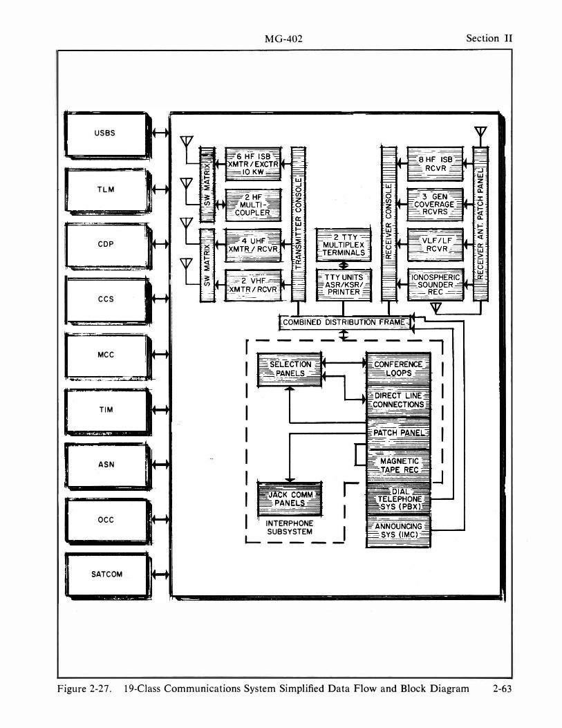
MG-402 Section II
USBS
TLM
COP
CCS
MCC r :l I I
�_�.-.:.... .:..ri... � . •
I I TIM I I
I I ASN I I
I J r I I OCC I INTERPHONE
SUBSYSTEM J L- ___
SATCOM
Figure 2-27. 19-CJass Communications System Simplified Data Flow and Block Diagram 2-63
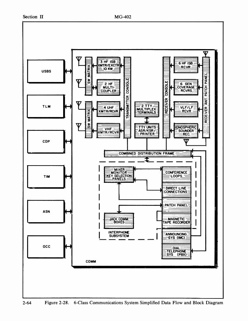
Section II
U SBS H
T lM H
COP H
TIM H
A SN H
OC C H
MG-402
Y-g E � EC3 HF I SB� � � � XMTR/EXCTR t-� �IOKW-=I'f �
;r. � § F=.... t==: 6 HF 158 ==:" = I:::::::::: ' t-=-RCVR = .,
r
r
17
� r-:----::: F== Cl F== :i F== � �
!::= r· F== � F== tw � �2HF= 0 r::: .. . t=" . = (/) MULTI-.=:::::: z �' , �COUPlER-= 0 g §
i== 6 GEN-= It �OVERAGE-= it-� RCVRS-= F= -=.!.= U � 0:: \oJ 0::
� � \oJ � - � t::c E"'" � F2TTY� \oJ �L. �4 UHF== � (/) MUlTIPlEX= frl � t=VlF/lF==
�I'f XMTRIRCVR z F RCVR = TERMIN AlS 0:: 0:: Cl � � 0::. �
I I=-:i E t===:=: E== t===:=: � F== � �L. t== VHF -==== t.. � ETTY UNITS �IL ��SPHERI� FASRIKSR1=
E� XMTR/RCVR I::::::: I' SOUNDER-� �PRINTERj: �RECo::::::::: � � � -
Y ..
COMBINED DI STRIBUTION FRAME ---t' 0 0 .
-----� ----I I �MIXER �ON ITO !f==. �CONFERENCE --=' I I �Y SELECTIC>t:!, I� � lOOPS---====:
�PAN ELS-=
I I , t=DIRECtlfN� • bCONNECTIONS::: I I
I I -" - PATCH PANEL=::
1- --- I I L =-JACK COM� =MAGNETlC� I I �BOXES = TAPE RECORDER
� � --
INTERPHONE I I �ANNOUNCING -= SUBSYSTEM ==-SYS (lMC).:::::: --------
====DI Al= �EPH�1.t =SYS (PBX;':::::: I'
COMM
�
IL I'
= ;= � \oJ
z Cl Il. :t: u � �-� Z Cl 0:: \oJ > iii U \oJ
� r= � --f:=
T
2-64 Figure 2-28. 6-Class Communications System Simplified Data Flow and Block Diagram
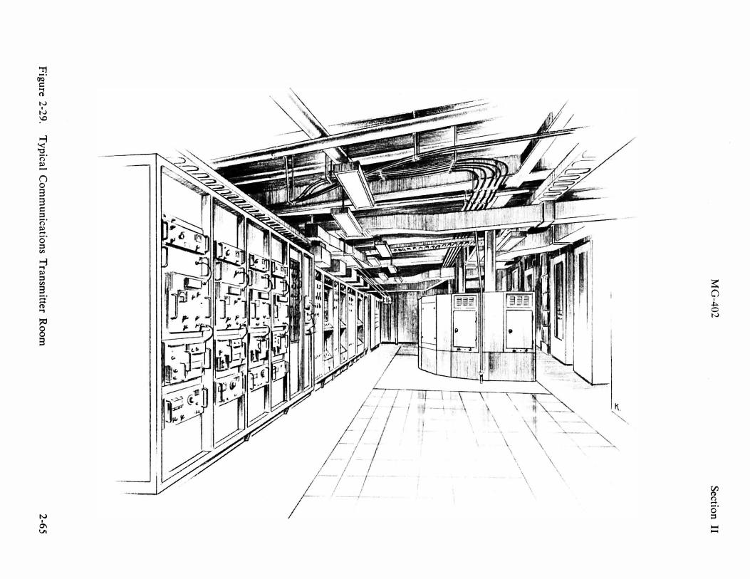
MG
-402
�-------.------
--
-
Fig
ure 2-29.
Ty
pica
l Co
mm
un
icatio
ns T
ran
smitter R
oom
Sectio
n II
2-6
5
Section II MG-402
INT ERPHON E SU BSYSTEM
The interphone subsystem provides the flexibility and service required to support operational missions .
The communications subcircuits are the conference loop type affording talk and/ or monitor access at the control of the operators . Normally, each of the operators i s assigned to monitor one loop and can be given talk and/or monitor capability of the other loops as required. There are two types of conference loops : local type and radio interface, which vary from 1 2- to 24-position capability each.
Direct l ines are interconnected between two or more interphone positions with both visual and audible signaling on the key-selection panels.
The key-selection panels and mixer monitor panels contain the pushbuttons to control the access to conference loops .
Cross-connecting in the Combined Distribution Frame ( CDF ) and patching at the jack field provide for the following :
Communication between any selected shipboard instrumentation areas operating on a press-to-talk basis, conferencing of any selected combination of shipboard instrumentation areas, and two-way radio communications as required to any shipboard instrumentation area or conference net.
Seven-track and 1 4-track magnetic tape recorders are capable of recording selected, simultaneous communication cIrcuits with time correlation .
2-66
The announcing system ( 1 Mc ) input can be connected to any conference loop with local muting provided.
Radio contacts with other ships or shore can be made via the patch panel to any instrumentation area by conference loops or telephones. Voice-actuated electronic relays or press-to-talk switching provides for transmitter keying. Tone-actuated relays supply remote keying of UHF transmitters.
DIAL TELEPHONE S U BSYSTEM
The dial telephone subsystem i s for general administrative and logistic support use.
The dial telephone (PAB X ) switchboard provides, in addition to the normal 3-digit shipboard extension dialing system ( a secondary communication system ) , a capability for patching into the interphone conference loops, and a radio communications l ink to a ship extension number.
In port, an umbilical cable connects the subsystem to shore l ines.
ENTERTAINMENT SU BSYSTEM
The entertainment subsystem consists of a radio broadcast antenna and a distribution faci lity to all staterooms, a television antenna system, and television antenna distribution facility to lounges and messrooms.
MG-402 Glossary
GLOSSARY OF N AU T I CAL TERMS AN D P H RASES ABAFT : behind, or farther aft. The
mainmast is abaft the foremast.
ABEAM : at right angles to the center line of the ship. Refers to an object outside the ship.
ABOARD : on or in a ship.
ACCOMMODATION LADDER : steps leading down a ship's side ; used for boarding.
ACKNOWLEDGEMENT : a statement that a message has been received.
AFT : at, near, or in the direction of the stern.
ALL HANDS : refers to every man aboard .
AMIDSH IPS : in the line of the keel ; sometimes halfway between the bow and stern.
ASTERN : behind the ship ; on a bearing of 1 80 0 from ahead.
AUX I LIARY : an assisting machine or vessel, such as an air-conditioning machine or a fuel ship.
BALLAST : heavy weights in the hold of a vessel or ship to increase stability by lowering center of gravity.
BEACON : an aid to navigation placed on or near a danger spot.
BEA M : the greatest width of a ship.
BEARING : the direction of an object expressed either in degrees either as relative or true bearing.
BELOW : beneath the main deck.
BERTH : a space for a ship to moor or anchor.
B ILGE : lower part of a vessel where waste and seepage collect.
B I LLET : an allotted place to sleep ; refers also to a particular man's duties aboard ship.
B LINKER : a set of lights at the masthead or on the end of a yardarm, connected to a telegraph key and used for sending flashing light signals .
BOA T : a small vessel which can be hoisted onto or carried by a ship.
BO'SN'S CHAIR : a seat, consisting of a short board fastened in the end of a line, on which a man may be suspended for working aloft or over the side .
BO'SN'S P I PE : a small , shrill whistle used by the bo'sn's mate in passing a call or in piping the side.
BOW : forward part of a vessel .
BRIDGE : the raised platform in the forward part of the ship from which the ship is steered or navigated.
BULKHEAD : a partition separating compartments ; corresponds to a wall in a building.
BUOY : a floating marker moored to the bottom which by shape and color conveys navigational information .
CABIN : the captain's quarters .
CAPSIZE : to overturn in a small boat.
CAST OFF : to let go .
CENTER LINE : imaginary straight line running from the bow to the stern of a ship.
CHAR T : a nautical map used as an aid in navigation.
CLEAR : to leave a port with all formalities concluded ; to empty ; to work clear, as of a shoal ; to untangle.
G- l
Glossary MG-402
CLOSE ABOARD : near to the ship.
COLORS : the national ensign.
COMMAND : term applied to a ship or ships under one officer; a directive indicating what to do and how to do it.
COMPANION WAY : passageway on board ship.
COMP AR TMENT : a space below deck between bulkheads, corresponding to a room of a building.
COUNTRY : the space near to a compartment or quarters, such as wardroom country or officers' country .
COURSE : the direction steered by a vessel expressed in degrees.
COXSWAIN : the enlisted man in charge of a boat and usually serving as steers-man.
DAMAGE CONTROL : maintenance of watertight integrity of the ship during batle or storms, including necessary repaIrs.
DA VIT : a curved metal spar fitting in a socket on the deck and projecting over the side of the ship for hoisting boats or handling weights.
DEAD AHEAD : directly ahead.
DEAD RECKONING : a navigator's estimate of the ship's position dependent upon course steered and distance run, independent of sights or bearings ; derived from "deduced reckoning."
DECK : corresponds to the floor of a building.
DOCK : a landing pier for boats or ships .
DOG : a type of bolt and nut used to secure watertight doors, hatch covers, or manhole covers.
DOLDDRUMS : belts on each side of the Equator in which, ordinarily, little or no wind blows.
G-2
DOUBLE BOTTOMS : watertight subdivisions of a ship next to the keel and between the outer and inner bottoms.
DOWSE : to put out a light ; to cover with water.
DRAFT : the depth of water from the surface to the ship's keel ; a detail of men.
EBB TIDE : condition along the coast when the tide is going out.
EMBARK : to go on board ship.
EMERGENCY SPEED : all the speed of which a ship is capable.
ENSIGN : the national flag; a junior commissioned officer in the Navy.
EVEN KEEL : floating level.
FAIR TIDE : a tide running in the same direction as the ship.
FAI RWAY : an open channel.
F ANT A I L : the part of the stern of the ship.
FAST : secure.
FA THOM : a unit of measurement equalling 6 feet.
FLANK SPEED : a certain prescribed increment above standard speed.
FLYING BRIDGE : a bridge on a ship having no supports and extending out from the control tower.
FORE AND AFT : running in the direction of the keel .
FORECASTLE : the upper deck forward of the foremast ; a forward compartment where the crew l ives.
FRAME : the ribs of a ship strengthening and supporting the plating.
FUNNEL : the smokestack of a ship.
GALLEY : the ship's kitchen .
GANGPLANK : a portable bridge used for boarding a ship from a dock.
MG-402 Glossary
G I G : ship's boat used by the command- LEE : away from the direction of the wind. ing officer. LIFELINE : a line secured along the deck
GUNWHALE : the upper edge or rail of a to lay hold of in heavy weather; a line ship or boat's side. thrown on board a wreck by a life-
HAND : a member of the crew. saving crew ; a knotted line secured to the span of life boat davits for the use
HANDY -BI LLY : a small portable pump. of the crew when hoisting and lowering. HA TCH : an opening in the ship's deck L IGHTSHIP : a small ship equipped with
for communication or for handling a distinctive light and anchored near stores and cargo. an obstruction to navigation or in shal-
HEAD : a ship's toilet. low water to protect passing ships.
HELM : a tiller ; the gear by which the LINE : the Equator; a seagoing term for
ship is steered. light rope or cable.
HIGH SEAS : the entire ocean beyond the L INE OFFICER : an officer who holds
three-mile limit where no nation has military authority in the chain of com-
special privileges or j urisdiction. mand, as opposed to a staff officer such
HULL : framework of a vessel together as a doctor or chaplain. May be im-
with all decks, deckhouses, inside plat-port ant for NASA personnel to under-
-stand. ing or planking, exclusive of masts, yards, rigging, all equipment, and all LOG : a book containing the official rec-
items generally classed as super- ord of a ship's activities.
structure. MAIN DECK : the highest complete deck
INBOARD : toward the center line of the extending from stem to stern and from
ship. side to side.
ISLAND : superstructure containing conning tower, navigation bridge, communication platform, flying bridge, etc.
JETSOM : goods which sink when thrown overboard at sea.
JETTY : a landing wharf or pier, a dike at a river's mouth.
KEEL : the backbone of a ship running from stem to sternpost at the bottom.
KNOT : one nautical mile per hour.
LADDER : a metal, wooden, or rope stairway.
LANDF ALL : first sighting of land at the end of a sea voyage .
LASH : to tie or secure.
LEAVE : special permission to be absent from ship or station.
MOORING : securing a ship to a dock or buoy, or anchoring with two anchors.
NAUTICAL MILE : the length of a minute of a great circle of the earth or 6,080.20 feet.
OFFICER OF THE DECK : the officer in charge of the ship during each watch and on deck as the captain's representative.
OVERHEAD : equivalent to the ceiling in a building.
P ASSAGEW A Y : a corridor or hallway on board ship.
P ILOT : an expert who conducts ships in and out of harbors and in dangerous waters.
POOP DECK : the partial raised deck and after structure at the stern over the main deck of a vessel.
G-3
Glossary MG-402
PORT : the left side of a ship facing for- STAFF OFFICER : an officer whose ward; an opening in the ship's side ; a duties are special rather than military, harbor. such as a doctor or chaplain.
QUARTERDECK : the part of the upper STARBOARD : the right side of a ship
deck reserved for honors and cere- looking forward.
momes. ST ATION BILL : a bill listing stations of
QUARTERS : living space ; all hands assembled at established stations for revIew.
REEF : a chain or ridge of racks, coral, or sand in shallow water.
RUNNING LIGHTS : lights required by l aw which are carried by a ship underway.
SCREW : propeller.
the crew at emergency drills and other shipboard evolutions.
STERN : the after part of a ship. SUBMERSIBLE PUMP : an electrically
driven pump that can be lowered into a flooded compartment.
SUPERSTRUCTURE : all equipment and fittings except armament extending above the hull.
SWAB : a rope mop. SCUTTLEBUTT : a container
water for drinking purposes the crew; a rumor.
of fresh SWELL : the heave of the sea. used by
SEA KEEPING : the ability of a ship to stay at sea for long periods of time.
SECOND DECK : a complete deck next below the main deck.
SECURE : to make fast; to tie ; order given on completion of a drill or exercise on board ship.
SHAKEDOWN CRUISE : cruise of a newly commissioned ship to test out all machinery and train the crew.
SICKBA Y : ship 's hospital or dispensary .
SIDE LIGHTS : the red and green running lights carried on the part and starboard sides respectively.
SKIPPER : slang for the captain.
SMOKING LAMP : the expression, "the smoking lamp it lit," means permission is given to smoke.
SOUND-POWERED PHONE : a phone powered by voice ; standard battle phone.
SQUARE A WAY : to get things settled down or in order ; to complete a job .
G-4
TAFFRAIL : a rail at the stern of a ship .
TOPSIDE : above decks.
UNDER WAY : a vessel is said to be underway when she is not at anchor nor made fast to the shore, nor aground.
UNDERTOW : a seaward current near the bottom in heavy surf.
WAKE : the track or trail in water which a vessel leaves behind.
WARDROOM : officers' assembly and mess room aboard a ship.
WATCH : a post or period of duty.
WATCH, QUARTER, AND STATION BILL : a list or chart giving the watch duties, billet and emergency, or battle station of every man aboard ship.
WEATHER DECK : the portion of the main, forecastle, poop, and upper decks which is exposed to the elements.
WINDWARD : into the wind; toward the direction from which the wind is blowing.
YARD : shipbuilding and repair depot for Navy vessels-as Boston Navy Yard.
YAW : to steer badly, zigzagging back and forth across the intended course.