handbook of electronic weighing · - the dual slope principle ra tiometric measurements ... dual...
TRANSCRIPT

K. Elis Norden
Handbook of Electronic Weighing
69 WILEY-VCH Weinheim . New York - Chichester - Brisbane - Singapore - Toronto

This Page Intentionally Left Blank

IS. Elis Norden
Handbook of Electronic Weighing
@3 WILEY-VCH

This Page Intentionally Left Blank

K. Elis Norden
Handbook of Electronic Weighing
69 WILEY-VCH Weinheim . New York - Chichester - Brisbane - Singapore - Toronto

K. Elis Norden Norden Consulting International Grossfeldstr. 76 CH-7320 Sargans Switzerland
This hook was clirefullv produced. Nevertheless, author and piihli.;her do not warrant therein tn he Tree of errors. Readers are advised to keep in mind tha t stntc'ments. data. illu\trntiuns. prlwduml de- tails o r other items niav inndvertentlv he inaccurate.
First Edition 1998
Library of Congress Card No.: applied for.
British Library Cataloguing-in-Publication Data: A catalogue record for this book is available from the British Library.
Die Deutsche Bibliothek - CIP Einheitsaufnahme Norden, K. Elis: Handbook of electronic weighing I K. Elis Norden. - 1. ed. - Weinheim : New York ; Chichester : Brisbane ; Singapore :Toronto : Wiley-VCH, 1998
ISBN 3-527-29568-2
0 WILEY-VCH Verlag GmbH. D-69469 Weinheim (Federal Republic of Germany). 1998
Printed on acid-free and low chlorine paper
All rights reserved (including those of translation into other languages). No part of this hook may be reproduced in any form - by photoprinting, microfilm. or any other means ~ nor transmitted or translated into a machine lan- guage without written permission from the publishers Registered names. trademarks, etc. used in this book. even when not specifically marked as such, are not to be considered unprotected by law.
Printing: Strauss Offsetdruck, D-69509 Miirlenbach Bookbinding: Wilhelm Osswald Rr Co., D-67433 NeustadtiWeinstraBe
Printed in the Federal Republic of Germany

Contents
1 1.1 1.2 1.3 1.3.1 1.3.2 1.3.2.1 1.3.2.2 1.3.2.3 1.3.3 1.3.4
2 2.1 2.2 2.2.1 2.3 2.3.1 2.4
2.4.1 2.4.1.1 2.4.1.2 2.4.1.3 2.4.2 2.4.2.1 2.4.2.2 2.4.2.3 2.5 2.5.1
Preface
Acknowledgements
Load cell principles Magnetic transducers The Oscillating strings transducer Strain gauge load cells - -
Electrical properties of strain gauges Specimen shapes - application of the strain gauges - Column type load cell - The bending beam load cell - The shear beam load cell Strain gauge load cells - electrical circuitry Analysis of sources of error
- -
Load cell designs and installation principles Load cell designs Load cell installation principles - Application of load Guide and restraining elements for the load carrier - Different types of guide and restraining elements Load cell installation in surface mounted static weighing systems - Weighbridges and platforms
- Weighbridges fixed with beam flexures or rods - Free floating platform or weighbridge - Low profile weighbridges
- High capacity weighbridge scales - Motor truck scales - Railway scales - Scrap scales
Load cell installation under hoppers and tanks - Mechanical requirements on foundation and
load carrier
1
4
5 5 8
10 10 14 14 16 17 20 24
31 31 35 35 38 39
42 42 42 45 46 47 47 49 51 52
52

vi
2.5.2 2.5.3
2.6 2.6.1 2.6.2 2.6.3 2.7
2.7.1 2.7.2 2.8
3 3.1 3.2 3.2.1 3.2.2 3.2.3 3.2.3.1 3.2.3.2 3.2.4 3.2.5 3.2.5.1 3.2.5.2 3.2.6 3.2.6.1 3.2.7 3.3 3.3.1 3.3.2 3.4
4 4.1
Contents
- Force shunts - pipe connections - Layout of load cell installation under
hoppers and tanks Load cell installation in travelling cranes - Load cell installation in the hook assembly - Load cells in the hoisting crab - Battery powered electronic crane scale Load cell installation in continuous casters and transfer vehicles - Continuous casting machines - Transfer vehicles Load cell installation in travelling weigh hoppers
Weighing electronics and data processing General principles Weighing electronics
Prerequisites on the weighing electronics Bridge excitation Electronic welghing instruments - Analogue display - Digital display Digital voltmeter systems Digitizing principles - Counting of unit pulses - The dual slope principle Ra tiometric measurements - Voltage to frequency conversion Microcomputer controlled load cell digitizer
Data processing - - Computerized weighing Sources of error due to the electronics and electrical installation
Data processing with microcomputer techniques
Static weighing systems System design and layout of technical procurement specifications
55
57 59 60 65 67
68 68 69 71
73 73 74 74 75 76 76 76 77 77 77 78 79 79 81 85 85 86
87
89
89

Contents Vi i
4.2 4.3 4.4
4.5 4.6 4.7
4.8
4.9
5 5.1 5.1.1 5.1.2 5.1.3 5.1.4 5.2 5.2.1 5.2.2 5.2.3 5.2.4 5.3
5.3.1 5.3.2
5.4 5.4.1 5.4.2 5.4.3 5.4.4
5.5
Specification: Specification: Specification:
Specification: Specification: Specification:
Specification:
Specification:
Dual weighbridge truck weighing system Railway car scale Platform scales, integrated in a data processing system for yield analyses Roller conveyor scale Weighing system for transfer car Overhead ladle crane scale with data transfer to the ground Weighing, length control and dataproces- Sing system for optimization of billet weights in a continuous casting machine Weighing and data processing system for scrap charging in a steel plant
Batchweighing principles and systems Batchweighing procedures - Positive batching - Negative batching - Overshoot of material - Cumulative batching Weighing accuracy and batching accuracy - Weighing accuracy - Batching accuracy - A further random source of error - Weighing and batching accuracy in practice Requirement on weighmg and batching accuray in the steelmaking process - Weighing and analysis accuracy - Required batch weight and maximum permissible
batching and weighing error Batchweighmg Systems - General principles - Hardware controlled batchweighmg - Software controlled batchweighing - Multiple batchweighing system with
Layout and technical procurement specification for an electronic batching system for alloying materials
microcomputer control
90 107
125 143 161
179
205
229
257 257 257 258 258 259 259 259 260 263 263
264 264
265 266 266 267 268
269
271

... rn Contents
6
6.1 6.1.1 6.1.2 6.2 6.2.1 6.2.2 6.2.3
6.2.4 6.2.5 6.2.6 6.3 6.3.1 6.3.2 6.3.3 6.4 6.4.1 6.4.2 6.5 6.5.1 6.5.2 6.5.3 6.5.4 6.5.5 6.6 6.6.1 6.6.2 6.6.2.1
6.6.2.2 6.7 6.7.1
6.8
6.9
Beltconveyor weighing and flow control of bulk solids 295 General principles 295 - Theoretical analysis 295 - Electronic belt scale - principal layout 296 Mechanical aspects 296 - Prerequisites for weighmg on a conveyor belt 296 - Idler misalignment 297 - Calculation of weighmg errors due to
idler misalignment 299 - Weighmg in inclined belt conveyors 301 - Belt pre-tension 302 - Weighmg in dog leg belt conveyors 303 Belt speed/travel measurement 304 - Installation of tachometers 304 - Tachometer measurement errors 305 - Total weighing errors in belt weighing installations 308 Load cell application in belt conveyors 309 - Calculation of load on the load cells 309 - Load cell installation designs 311 Beltwelgher instrumentation - belt scales 314 - General principles 314 - Microcomputer controlled belt scale 314 - Belt scale and batching unit 3 16 - The Resometric belt scale 317 - The nucleonic beltweigher 318 Material flow control with belt conveyor weighing 319 - General control principles 319 - Belt feeders for constant flowrate 320
- Belt feder with separate weighing belt for constant flowrate 321
- Integrated flow control systems with belt feeders 322 Beltweigher testing 323 - Accuracy checking of belt feeders without
interruption of the material feed 323 Technical procurement specification for belt weighing system to be installed in an existing belt conveyor 326 Technical procurement specification for a belt feeder with separate weighing belt 343

Contents ix
7 7.1 7.2 7.2.1 7.2.2 7.2.3 7.2.4 7.2.5 7.2.6 7.2.6.1 7.2.6.2
8 8.1 8.2 8.3 8.3.1 8.3.2 8.4 8.4.1 8.4.2 8.4.3
8.5
9 9.1 9.2 9.3 9.4 9.5 9.5.1 9.5.2 9.5.3 9.6 9.7
Flow measurement of bulk solids General Measuring principles - Measurement of impact - Measurement of impetus - The K-SFM flowmeter - Measurement of coriolis force - -
Force measurment on a rotating plate Differential batching with weigh hopper - Calculation of feedrate - Integration of the discharged material weight
363 363 363 363 364 365 367 369 369 371 372
In-motion weighing 375 General principles 375 Dynamic forces on the vehicles causing weighing errors 375 Layout of weighbridges 380 - Long weighbridge for single draft we-g 380 - Short weighbridge for dual draft weighing 381 Application of in-motion weighing systems 383 - In-motion scale for railway cars 383 - In-motion weighing of air freight and cargo 386 - Weigh-in-motion (WIM) system
389 Layout and technical procurement specification for an in-motion weighing system for railway cars 391
for highway weight law enforcement
Checkweighing scales General principles Working principles of a checkweigher Package weight control theory Checkweigher Accuracy Checkweigher design and applications - In-feed mechanisms - Scale conveyors and platforms - Reject mechanisms Automatic weigh - price labelling Checkweigher electronic components
411 411 411 412 419 422 422 424 425 428 428

X Contents
10 10.1 10.2 10.3 10.4 10.5 10.5.1 10.5.2 10.5.3 10.6 10.7 10.7.1 10.7.2 10.7.3
11 11.1 11.2 11.3 11.4 11.5 11.6 11.7 11.8 11.9 11-10 11.11 11.12
Counting scales General Principles Counting principles Sources of error - counting accuracy Application and uses of counting scales Design and operational principles of counting scales - Counting scales with strain gauge transducer - The moving coil transducer - Dual platform counting scales Technical data Typical counting scale designs - Single platform counting scale - Double platform counting scale - Dual hybrid counting scale
Testing and calibrating procedures General principles Testing principles - static scales Testing procedures - static scales Testing principles - batching scales Testing procedures - batching scales Testing principles - beltscales and dosimeters Testing procedures - beltscales and dosimeters Test results - test report Testing of static scales Testing of batching scales Testing of belt conveyor scales Testing of dosimeter with belt conveyor scale
43 1 431 43 1 432 433 434 434 435 436 437 437 437 438 439
441 441 44 1 442 449 449 452 454 458 459 463 465 467
Index 469

Preface
The objective of this book is to systematically step by step analyse the requirements and evaluate the theoretical basis for the application of electronic weighing in industrial processes, leading to optimum design and layout of computer controlled weighing systems for static weighing, batch weighing of bulkmaterials and liquids, weighing and control of material flow as well as weighing of vehicles in motion.
In static weighing systems comprising platform scales, truck- and railway scales, crane scales and transfer car scales, the mechanical design of the load carrier is usually determined by operational requirements, and from the weighing point of view it is a question to choose and install the load cells under the load carrier so that a maximum of opera- tional accuracy and reliability is obtained.
In batch weighing systems also all mechanical parts such as material bunkers, weigh hoppers, material feeders and conveyors form integral parts in the integrated system, with the electronic components with load cells, weighing instruments, program logic control, and computer for data processing and presentation in real time.
Weighing of material flow in existing belt conveyors designed for transfer of bulk materials often present considerable problems with regard to weighing accuracy, but high precision systems and systems for control of the material flow usually comprise specially designed belt conveyors.
Systems for in-motion weighing of vehicles require special care of the surrounding stretch before and after the weighbridge to reduce influences of disturbing forces from revolving movements of the vehicle, and the electronics must be designed to integrate the weight signal over a certain short period of time to obtain an average representing the true axle load.
To provide an optimum of performance in an integrated mechanical and electronic system, the technical design data of the system and the reliability of the components play an equal role. A system with extreme accuracy, but which frequently breaks down, provides no better overall performance than a less accurate system with for instance conservatively rated components with extreme operational reliability.

2 Preface
An optimum is reached when possible wear out on mechanical parts are reduced to a minimum, and the electronic system components are desig- ned to work within conservative levels.
To be able to evalulate the influence on the weighing accuracy of, for instance disturbing forces acting on the load cells in a weighing system, it is important to understand the theoretical background for the conversion of a mechanical force into an electric property, which is the basic principle of a load cell.
Hence, chapter 1. reviews the principles of different types of load cells, and especially analyses the theoretical background and the operatio- nal characteristics for the strain gauge load cell, which is the overwhel- mingly used load cell design in industrial weighing.
Chapter 2. presents different mechanical designs of the load cells with their individual application and installation reuirements and limitations. Theoretical analysis and formulas for calculation of the influence of disturbing forces are applied to practical cases for static weighing in industry.
In chapter 3. introduction to the state of the art of industrial weig- hing electronics and data processing in computers is reviewed, including sources of error influencing the operational reliability and weighing accuracy of the weighing electronics.
Chapter 4. contains systems layout and basic technical specifications of equipment hardware and software menus as a basis for procurement of the static weighing systems, comprising platform scales, truck- and railway scales, roller conveyor and transfer car scales, as well as crane scales and weighing systems for scrap charging in steel plants and for optimizing of billet (slab) weights in continuous casting machines.
Batchweighing principles and systems are presented in chapter 5. including the analysis of weighing and batching accuracy, and the requi- rement on weighing and batching accuracy in the steel making process.
Furthermore the principles of hardware and software menus for computer controlled batchweiging systems are described, including a complete technical procurement specification for a batching system for alloying materials in a steel plant, with a r e f i g system for the day bunkers, whereby also the principles for calculation and improvement of metallic yield and precision of aim in the alloying in real time are discussed.
In chapter 6. the general principles for beltconveyor weighing of bulk solids are described with analyses of sources of error due to the mecha- nical installation of the load cells and the tachometers or other equip- ment for measurement of belt transfer. The principles for weighing in

Preface 3
belt conveyors with the Resometric and the Nucleonic belt scales, as well as the principles and equipment for control of the material Row and on- line mixing of materials with belt feeders are described.
A technical procurement specification for a beltweighing system to be installed in an existing belt conveyor is also included, and the chapter ends with a technical procurement specification for a belt feeder with a separate weighing belt.
In chapter 7. flow measurement of bulk solids through other measuring principles, such as measuring of impact, or impetus, or Coriolis force etc are analysed.
Chapter 8. contains the principles for in-motion weighing and layout of systems for weighing of carts for air freight and cargo handling, as well as examples of systems for weighing of railroad cars, and for weigh- in-motion (WIM) system for highway weight law enforcement,
Furthermore, a complete technical procurement specification including the software menu for an "in-motion weighmg system of railway cars" ends the chapter.
In chapter 9. the theoretical principles and practical designs of check- weighing scales are presented. Such scales are being used in packing industries for filling and for checking and sorting prefilled bottles, tins and packages with a very precise weight of material. As the weighing and sorting is made in running production lines great efforts are put in to obtain a smooth operation with in-feed mechanisms, weighing in-motion and reject mechanisms, all making an integral part of a checkweighmg scale.
Chapter 10. presents the theory, design and operational principles of counting scales, which today have become important tools in all kind of industries for delivery and inventory control of materials in stockrooms, warehouses, production departments, printers of books and newsprint etc.
When a weighing system is installed it is important that a comprehen- sive calibration and testing of the operational performance is carried out, as a system that delivers false information can be disastrous for the process and cause considerable economical losses.
As the equipment often works under extreme arduous conditions, there are possibilities that the calibration and operational performance may change with time, and it is therefore equally important that regular tests with eventually needed adjustments are carried out.
To facilitate such tests and calibration procedures, the principles and procedures for testing of static scales, batching scales, as well as belt scales and dosimeters are presented in chapter 11. including lay out of test reports with forms for test data and calculation of test results.

Acknowledgements
As I have already mentioned in the preface, the intention of this book is to give the reader a theoretical and practical background for the choice of electronic weighing equipment and systems for different industrial applications, including comprehensive technical specifications to serve as a basis for procurement of equipment hardware and software.
Hence, it has been a desire to exemplify the principles and the components as well as the systems with descriptive material and photo- graphs from renowned suppliers of electronic weighing.
This has been made possible through generous support of illustrative material from manufacturers of weighing equipment and suppliers of components in Europe and USA.
My sincere thanks goes to all these companies, and it is my hope that I have been able to provide an impartial and apprehensible basis for procurement of the right equipment for the right application in the industrial processes, and thus avoid malfunctional installations through a better understanding of requirements and possibilities, leading to an improvement of the apprehension of responsible suppliers.
My very special thanks goes to my wife Beatrice, who has not only supported and encouraged me in writing this book, but also for her great contribution in producing the time consuming graphic material illustrating principles and systems layout.
K. Elis Norden

1 Load cell principles
To be able to analyse the requirements on load cells and their installation, as well as the influence of disturbing forces that may endanger the weighing accuracy in a weighing system, a basic knowledge regarding the types of load cells being used in industrial weighing and their technical characteris- tics is needed.
Different physical principles can be utilized for measuring of forces, but in industrial weighmg systems there are mainly three types being used, namely:
1. Magnetic transducers, measuring change in magnetic permeability.
2. Oscillating strings transducers, measuring change in frequency.
3. Strain gauge transducers, measuring change in resistance.
The basic principles and design of load cells based on these principles will be discussed in the following sections.
1.1 Magnetic tranducers
Of the magnetic type transducers, the best known is the "Pressductor" load cell developed by ASEA of Sweden (now-a-days ABB), which utilizes the change in permeability in a magnetic core occuring when a force is applied to the core.
Owing to their characteristic electron structures, most atoms have a magnetic moment with a north and a south pole like a magnetic compass needle. The ferromagnetic elements, iron, cobalt and nickel, have a remark- able property - when in solid state they form continuous areas of "macro- scopic" size of 1 - 10 pm, in which the magnetic moments of the atoms act in the same direction. These areas are called the "Weiss" domains, and each exerts a powerful magnetic flux in a certah direction. Normally, the mutual orientation is such that the material externally is non-magnetic.

6 Load cell principles
When a solid body is subjected to a mechanical stress, energy is stored in the body, resulting in a certain minute deformation. There are however materials that also produce other effects, for example: ice melts when pressure is applied, quartz releases charges so that an electric field appears, and so on.
Ferromagnetic elements change the magnetic moments of the domains when pressure is applied, resulting in changes in the magnetic characte- ristics in the directions in which the mechanical forces act. This is called the magneto-elastic effect, which is the basis of the pressductor force transducer.
The principle for the pressductor is shown in figure 1.1. A square sheet of transformer iron is being magnetized along one diagonal (a). Magnetic isotropy is assumed, i.e. the magnetic flux density vector (B) is parallel to the magnetizing field vector (H), and the vertical and hori- zontal components B, = B,.
(a)
Figure 1.1 The Pressductor principle
Anisotropy caused by the magneto-elastic effect will occur when vertical forces are applied (b), so that the permeability decreases in the direction of the forces and B, 5 B,.
The pressductor transducer consists basically of a laminated iron core with two perpendicular windings as shown in figure 2.2 (a). An alterna- ting current through the "primary" winding sets up an alternating magnetic field in the core according to the pattern "no load" in figure 1.2 (b), whereby no voltage is induced in the perpendicular "secondary" winding.
When load is applied to the iron core, figure 1.2 (c), the change in permeability discussed above, causes the magnetic flux lines (B) to change

Load cell principles 7
the angle (@), whereby the current through the primary winding enclosing the cross section (A) will set up a flux (@) through the secondary winding:
A magnetic field varying with time will induce a voltage (V) in the secondary winding:
volts
The induced voltage (V) is depending on the magneto-elastic properties, influenced by the applied force, so that the induced voltage principally is proportional to the applied force.
Figure 1.2 The Pressductor transducer
The calibration curve of the pressductor is principally S-shaped, and a linearization is needed to obtain high accuracy. This is achieved partly by using core material which contains internal stresses, and partly through external linearization elements.
The output impedance of the pressductor is very low, only about 1 Q per rated ton, and the current in the primary winding causes magnetic saturation in the iron core, so that the load cell is insensitive for exter- nal influences from currents, magnetic fields, insulating resistance etc.
The output is high; at a frequency of 50 Hz about 1 mW per ton rated load, proportional to the capacity of the load cell.
However, the output of the pressductor has an inductive characteristic, which causes a frequency dependence of the signal occuring across the external load impedance. This can however be eliminated through correct selection of the external impedance.

8 Load cell principles
(a) (b)
Figure 1.3 Pressductor load cells (Courtesy of ASEA)
A pressductor load cell for 50 kg - 20 t, class 0.05 %, with a second linearizing core (3) is shown in figure 1.3 (a), and for loads between 40 t - 160 t, class 0.1 % in figure 1.3 (b).
1.2 The oscillating strings transducer
The oscillating striigs transducer is mainly being used in laboratory scales and other scales for smaller weights, but also in industrial applications the oscillating strings transducer is being used in for instance platform and belt conveyor scales.
The transducer operates according to the elementary physical laws that a current through a wire placed in a magnetic field causes a motion of the wire perpendicular to the magnetic field, and that through the motion a voltage is induced in the wire, which if connected to an elec- tronic oscillating circuit causes the wire to vibrate at the natural fre- quency (fo),
f, =
Here are:
which can be calculated according to the equation:
2.L *gA Hz (3)
(L) =
(F) =
(6) =
(A) =
the length of the wire, the tensional force applied to the wire, the density of the wire material, the cross section area of the wire.
Figure 1.4 below illustrates the principle of operation. The vibrating strings or wires (B) are placed in the airgap of two permanent magnets,

Load cell pririciples 9
and each of them is connected to an electronic oscillator circuit, which causes the strings to vibrate at their natural frequency (fJ.
The strings are preloaded through a reference mass (C), and when the unknown load (A) is applied to the load connection (D) through a string at a certain angle (E), the left string (Bl) will be exposed to an increased tensional force, which increases the natural frequency (fJ of that string, whereas the other string (B2) will lower its natural frequency (fJ, due to the decrease in the tensional force.
Figure 1.4 The principle of the oscillating strings transducer
The two frequencies are linearized through an electronic circuitry and the difference (6f) = (fl - f2) which represents the applied load (A), produces a pulse train (df). A direct weight reading is achieved by sampling the pulse train in a pulse counter during a predetermined time, and as this oscillating strings load cell compares the unknown force with a known reference mass (C), it is independent of the earth's gravity.
In oscillating string load cells with only one preloaded string, the oscillating frequency (f,) can produce an opening gate into a counter for sampling of a second constant frequency (fJ, whereby the number of pulses counted represents the applied force (F), according to the voltage to frequency conversion principle as described in chapter 3. "Weighing electronics and data processing".
The oscillating string load cells are reported to have high accuracy, and extreme long term stability.

10 Load cell principles
1.3 Strain gauge load cells
The overwhelming majority of manufacturers of electronic we- equip- ment, however, use the strain gauge type load cells in various designs. Because of its importance, the theoretical background of the strain gauge load cell will in the following section be analysed more in detail.
The strain gauge is fundamentally an electric resistance made as a pattern of parallel wires or thin metal foil embedded into an insulating base of plastic material. Some typical patterns of foil strain gauges are shown in figure 1.5.
Fig. 1.5 Foil strain gauge patterns (Courtesy Of HBM)
The stamp-like element is bonded onto the surface of a steel body, and follows the elongation or compression of the surface minutely. with the effect that the magnitude of the resistance varies accordingly. It is this change in resistance, which is proportional to the applied force on the steel body, which is measured very precisely.
1.3.1 Electrical properties of strain gauges
The resistance (R) of a metallic wire or foil with the resistivity (B), the length (L) and the cross section (A) can be calculated according to the formula:
52 (3)

Load cell principles 11
To study what happens when minute mechanical changes occur the loga- rithmic derivative of equation (3) is established:
(4) dR df3 dL dA R O L A
+ - - _ -
The volume (V) of the wire or foil is: (V = L.A), with the derivative:
dV = A - d L + L - d A ( 5 )
The change in volume (dV) for a fractional change in length ( E ) of a wire or a long slim body is:
dV = L . ( l + € ) . A . ( l - PE)’
where (p) is the Poisson’s constant.
As the fractional change in length ( E
grade terms of ( E ) can be neglected,
dV = L . A * E . ( l - 2p)
and through insertion of (6):
dV = A * d L * ( l - 2p)
- LA (6)
dL L
= -- ) is very small, the higher
so that the equation reads:
(7)
A combination of the equations (5) and (8) gives:
A.dL + L.dA = A . d L * ( l - 2p)
or: dL dA L A - .2p = _ -
which inserted in (4) gives:
dR d13 dL R f 3 L _ - - - t - ’(1 + 2p)
An important factor in the design of strain gauge load cells is the gauge factor (G), which determines the relation between the resistance change for a fractional change in length.

12 Load cell principles
The gauge factor (G) for a strain gauge is defined:
dR/R dL/L
G = -
which inserted in (11) gives:
dB/B dL/L
G = l t 2 p + -
dB/B The last term (-) is positive for most materials and close to zero
dL/L for some;
between:
in a few cases it is negative, and (p) = 0.3.
Hence, theoretically the gauge factor for the strain gauges varies
1.6 5 (G) 5 2.4 (14)
and for most strain gauges the gauge factor (G) = 2.0.
1.3.1.1 Heat dissipation
The strain gauges in a load cell are connected into a Wheatstone’s bridge circuit, whereby, when a force is acting on the load cell, the resistance change in the individual strain gauges causes an unbalance of the bridge.
The heat dissipation of a strain gauge is a limiting factor on the allowable current through the strain gauge and consequently on the un- balance voltage output of the load cell.
This heating effect will be illustrated on a typical strain gauge, with a nominal resistance of R = 120 Q, grid dimensons (10.5) mm, and the foil made of Constantan with a thickness of approximately 0.003 mm.
The power dissipated in the strain gauge is (W = R - f ) Watts. With an excitation voltage to the Wheatstone’s bridge of 12 V, the current through the strain gauges will be 50 mA, and the power 0.3 Watts.
As 1 W represents 0.996 J/sec, the total heat dissipation in the strain gauge is (0.3.0.996) = 0.299 J/sec.
The weight of the metallic strain gauge grid with the dimensions 10.5 mm, and thickness 0.003 mm is approximately 0.0043 grams.
As the Constantan foil has a specific heat value of 0.406 J/T/g, the strain gauge grid has a heat capacity of (0.0043-0.406) = 0.0017 J/”C.
If no heat dissipation into the load cell specimen would take place,

Load cell pririciples 13
there would be a temperature rise in the grid of:
0.299 J/sec 0 .OO 17 J/"C
= 175 "C/sec
which gives an indication of how important it is to have an effective heat dissipation into the load cell specimen to obtain stable results of the measurements.
The heat dissipation is also a limiting factor for the design of load cells with strain gauges for very small loads.
1.3.1.2 Linear thermal expansion
Temperature dependent changes of the strain gauge resistance occur in the applied gauge owing to thermal linear expansion coefficients of the grid and the load cell specimen material. If there is a difference in these, there will be a resistance change in the strain gauge indicating an appa- rent mechanical strain in the specimen. The representation of the appa- rent strain as a function of temperature is called the temperature charac- teristic of the strain gauge application.
In order to keep apparent strain through temperature changes as small as possible, the strain gauge grid is made of material with a certain linear thermal expansion coefficient matching the thermal expansion of the load cell specimen. For instance, for ferritic steel: (a = 11*10"/K), and for aluminium: (a = 23. 1O4/K), etc.
1.3.1.3 Temperat w e variations
In the strain gauge load cell, temperature variations naturally have an effect on the zero load balance of the Wheatstone's bridge formed by the strain gauges, and also on the magnitude of the modulus of elasticity (E) of the steel specimen. In the design of the load cells these effects are however compensated for so as to reduce them to a minimum.
The zero balance can be compensated for through small resistances with the appropriate resistance temperature coefficient in the arms of the Wheatstone's bridge.
The change in modulus of elasticity can be compensated for in two ways, either: 1) through a resistance with the appropriate resistance temperature coefficient in serial with the bridge excitation, or: 2) by making the strain gauges themselves of an alloy which has an appropriate

14 Load cell principles
resistance temperature coefficient to match the increased deflection of the load cell specimen through the change in the modulus of elasticity with the temperature.
Most manufacturers of strain gauge load cells present data where they guarantee that these effects have been reduced to less than 10 % of their original values.
1.3.2 Specimen shapes - application of the strain gauges
Different shapes of specimen, such as columns or bending beams etc, can be used as measuring specimens in strain gauge load cells, as will be demonstrated in the following section.
1.3.2.1 Column type load cell
The principle of the conversion of a mechanical force into a measurable electric property in a strain gauge load cell will in the following be illustrated on a column type specimen as shown in figure 1.6.
Figure 1.6 Column type specimen
A force (F) N applied along the longitudinal axis of a cylindrical steel column, with the length (L) cm and the cross sectional area (A) cm’, is causing a strain (0) in the steel column, which can be calculated accor- ding to the equation:
F A
o = - N/cmZ

Load cell pririciples 15
According to Hook‘s law, the strain, within the proportionality limit, can also be expressed:
u = 6.E N/cm2 (17)
dL L
Here
modulus of elasticity for the specimen. (For steel E = 21-106 N/cmZ).
(e = - ) is the relative fractional change in length, and (E) the
A combination of the equations (16) and (17) above gives:
dL F L A * E
- e =
The strain gauges that are bonded onto the surface along the longitudinal axis of the steel column are exposed to this fractional change in length, and hence there will be a resistance change according to the definition of the gauge factor (12):
dL 1 dR L G R _ - _ . - -
and finally combining the equations (18) and (19) we get:
dR G R A - E
- - - - .
which shows that the resistance the applied force (F), within the
change (dR) is directly proportionality limit for
proportional to steel, with (G),
(E), (A) and (R) principally being constant. As the volume of the steel column remains unchanged, and as there
is a fractional change in length (t) when the force (k F) is applied, it is obvious that there will be a lateral contraction or expansion perpen- dicular to the longitudinal axis.
Hence, the strain gauges that are bonded perpendicular to the longi- tudinal axis will be exposed to a deformation:
where (p) is the coefficient of lateral contraction or expansion (Poisson’s constant).
As ( p ) = 0.3, the strain appearing in the laterally bonded strain gauges will be approximately 30 % of the strain occuring in the strain gauges along the longitudinal axis.

16 Load cell prirtciples
The perpendicularly mounted strain gauges form two branches in the Wheatstone’s bridge, and provide principally for automatic temperature compensation of the zero balance of the bridge.
A typical compression load cell is shown in figure 1.7 below:
Figure 1.7 Compression load cell (Courtesy of Phiups AG)
1.3.2.2 The bending beam load cell
A typical design of a bending beam load cell i shown in figure 1.8 below. The load cell is fixed to the supporting structure through bolts in the two holes to the left, and the load (F) is applied through the hole to the right.
Figure 1.8 Bending beam load cell (Courtesy of HBM)
Load cell principles 17
I I
L-.---l ' t 1 / ( I ' @ i i 1 ; I 1 ! - I 1 I
The bending beam load cell with the lever arm (L) is exposed to a bending moment (F-L), and the resistance change in strain gauges can equivalent to equation (20) above be calculated according to:
/I////////////// //'/I/////.'//
dR G - D F . L R 2 - E - I _ - - . -
q,//l
where (I) is the moment of inertia of the cross section with the diameter (D). (G) is the gauge factor according to equation (12) and (E) is the modulus of elasticity for the specimen.
This shows that the resistance change (dR) is proportional to the applied bending moment (F-L), with (G), (D), (E) and (I) principally being constant.
Hence, the resistance change (dR) is also directly influenced by the lever arm (L). In some cases, especially at high loads, it can be difficult to obtain a clearly defined length (L), which thus will cause a propor- tional error in the relationship between the force (F) and the resistance change (dR).
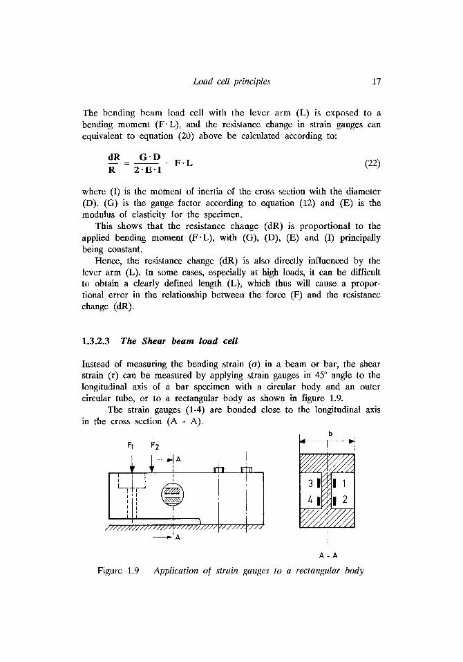
1.3.2.3 The Shear beam load cell
18 Load cell principles
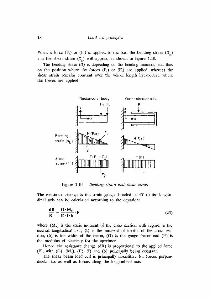
When a force (F,) or (Fz) is applied to the bar, the bending strain (a,) and the shear strain (Z ) will appear, as shown in figure 1.10.
The bending strain (a) is depending on the bending moment, and thus on the position where the forces (FJ or (F,) are applied, whereas the shear strain remains constant over the whole length irrespective where the forces are applied.
F
Rectangular body
F 2 Fi
Shear strain ( T F )
Outer circular tube
t
Figure 1.10 Bending strain and shear strain
The resistance change in the strain gauges bonded in 45" to the longitu- dinal axis can be calculated according to the equation:
F dR G-M, R E - I - b - =-.
where (M$ is the static moment of the cross section with regard to the neutral longitudinal axis, (I) is the moment of inertia of the cross sec- tion, (b) is the width of the beam, (G) is the gauge factor and (E) is the modulus of elasticity for the specimen.
Hence, the resistance change (dR) is proportional to the applied force (F), with (G), (MJ, (E), (I) and @) principally being constant.
The shear beam load cell is principally insensitive for forces perpen- dicular to, as well as forces along the longitudinal axis.