handbook of industrial - heat-trace.co.krheat-trace.co.kr/handbook.pdfhandbook of industrial...
TRANSCRIPT

Handbook ofIndustrial
Electric Heat Tracing
TheHeat Tracing AuthorityTM
System Design
Product Selection
Installation
Commissioning
Maintenance

ContentsContents Page 2
HEAT TRACE LIMITED11� The Innovation Culture – the Past, the Present and the Future 4-5� Heat Trace Limited 6-7
INDUSTRIAL HEAT TRACING – An Introduction22� What is it? 8� What is its purpose? 8� Steam or Electric? 8� The Need? 8� The System? 8� Safe Practice 9� Applicable Standards 9� Applications 10-11
SYSTEM DESIGN – General33� Objective – A safe system that works 12-13� Considerations in Hazardous Areas 14-17� Heating Loads 18-19� Temperature control 20� Circuit monitoring 21
PRODUCTS AND PRODUCT SELECTION44� Heating Cables – Generic types 22-25� Heating Cables – Selection Guide 26-27� Typical Long Pipeline Applications 28-29
� Parallel, self-regulating 30-35� Parallel, constant power 36-39� Series resistance, Longline 40-43
� Termination Components 44-45
� Temperature Control – Selection Guide 46-47
� Type I Temperature controllers - Maintaining above a minimum point 48-49� Type II Temperature controllers - Maintaining within a broad band 50-51� Type III Temperature controllers - Maintaining within a narrow band 52-53
� Circuit Monitoring Equipment 54-55

ContentsContentsPage 3
INSTALLATIONS 55� Installation and System Testing 56-63� Commissioning & Documentation 64-65� Maintenance 66-67
EVOLUTION – The Complete Design Tool 66� Evolution – The Complete Heat Tracing System Design Suite 68-69
� A Customer’s Perspective 70-71
� Enquiry Management 72-73
� Enquiry Modelling 74-83 Enquiry Details 74 Design Selections 75 Heater Selection 76 Pipe Groups 77 Pipe Dimensions 78-79 Bill of Material 80-81 Quotations and Reports 82-85

The Past
When Heat Trace Limited was founded in 1974, electric heat tracing was in its infancy – most heat tracing used steam as its heat source at that time.
In the four decades since, electric heat tracing has grown into an industry in its own right. Heat Trace Limited has played a prominent role in its growth throughout as a Leader in Innovation.
From the start, Heat Trace developed products and systems meeting Heat Trace’s own corporate objectives of improving:-
safety, efficiency, reliability and performance.
The world’s first parallel resistance cut-to-length Heat Tracer heating cable was patented, developed and launched by Heat Trace Limited in 1975. It remains within our product range to this day, bearing testament to the significance of this invention.
Heat Trace Limited were perhaps the first Heat Tracing company to recognise the important link between control technology and the “safety, efficiency, reliability and performance” of heat tracing installations.
The company patented PowerMatch, a self-regulating proportional controller that turns heater power up or down in response to changes in heat losses. Although launched almost 20 years ago, the benefits of ambient proportional control to safety and efficiency have only recently been recognised on a global basis.
Innovation-led technology resulted in Heat Trace Limited becoming the industry’s technical leader…
11
The Past, the Present, ......and the Future
Page 4
The Present
Heat Trace’s Innovation Culture has culminated in its position as the Technology Leader within our Industry today. This position is demonstrated by:-
1. The largest and best range ofself-regulating heating cables
� Highest continuous ‘maintain’ temperature (200ºC)� Highest continuous ‘withstand’ temperature (300ºC)� Widest voltage range (12 to 1000V)� All inherently temperature-safe (IT-S)
Heat Trace’s range of self-regulating heating cables cater for most heat tracing applications
2. The highest temperature cut-to-lengthHeat Tracer in the world.
Heat Trace’s patented mineral insulated, metal sheathed, type AHT heating cable can withstand 425ºC continuously, and deliver up to 200W/m.
The AHT tracer can cater for virtually all applications outside the capability of the self-regulating tracer range.
3. EVOLUTION - the world’s most advancedheat tracing Design Tool (See section 6).
Additionally, Heat Trace’s range of electronic control and monitoring equipment extends from simple thermostats to microprocessor controls capable of integrating into overall plant SCADA and DCS systems.
Today, Heat Trace Limited is a global company providing complete heat tracing solutions. In addition to systems manufacture, services include consultancy, system design, installation and commissioning, project management, maintenance and training.
Heat Trace Limited continues to be…
TheHeat Tracing AuthorityTM
TheHeat Tracing AuthorityTM
HEAT TRACE LIMITED - AN INNOVATION CULTURE

11
The Past, the Present, ......and the Future
Page 5
The Future
Heat Trace’s emphasis on an Innovation Culturehas resulted in an extensive and active Research and Development Department, located at the Heat Trace Innovation & Technology Centre near Manchester UK.
In addition to test equipment the Centre has its own specialist pre-production, prototyping and compounding facilities, including polymer, elastomer, mineral and metal continuous extrusion capability.
The Technology Centre is fully equipped to carry out all international standard type testing. In addition, the Centre has a 40ft (12m) x 7ft (2.2m) x 6.5ft (2m) refrigerated cold room facility that allows us to carry out product and systems testing down to -40ºC.
At the time that this brochure went to press, Heat Trace Limited had multiple patents/patent applications in the course of development, and an extensive Product Development project list, mainly involving semi-conductive polymer formulations.
These projects will result in many new and unique products and processes over the forthcoming decade ensuring Heat Trace Limited’s position as the Technology Leader within its industry sector….
Heat Trace Limited will remain…
TheHeat Tracing AuthorityTM
Cold Room facility
Gravimetric Blending System
HEAT TRACE LIMITED - AN INNOVATION CULTURE

Heat Trace Ltd has been manufacturing electrical heating cables in the U.K. since 1974.
The main manufacturing facility and headquarters of the company is at Helsby in the North West of England. This factory houses the main processing equipment for the manufacture of semi-conductive self-regulating heating cables; core compounding, heating matrix extrusion, and other more recognised standard cable making processes. The main item of capital equipment is the Electron Beam Unit – one of only two similar units in the U.K., and one of only a few in Europe.
The Helsby Headquarters handles sales to all countries around the world. Exports account for over 90% of Heat Trace sales.
In addition, the Heat Trace Innovation & Technology Centre is located close to Manchester, only 56 km from the Helsby headquarters. The Bredbury complex has been a Heat Trace owned premises for over 25 years, and constant power heating cables are made here.
Heat Trace Limited in the UK11
Heat Trace Limited ………………. In the U.K.
Page 6
Helsby Headquarters
Bredbury Manufacturing Facility
Research & Development Laboratoryat Bredbury

Heat Trace Limited in the UK 11
Heat Trace Limited
Page 7
3m Pipe Test RigExtrusion Temperature Control Unit
24 Spindle Braider
Skin Effect Test Rig
Control Panel for 3m Pipe Test Rig

Heat Tracing – What is it?
“Heat Tracing (or Trace Heating, or Surface Heating) is the method of applying heat to a body, or to a product (liquid, powder, or gas) contained within a system (pipework, vessel or equipment) for storage or transportation, in order to avoid processing problems or difficulties.”
Heat may be applied, for example, to:-
� Liquids - to prevent freezing - to enable pumping by reducing the viscosity of the liquid� Powders - to eliminate condensation from the walls of equipment
that could result in ‘clogging’ of the product� Gases - to prevent hydration due to a drop in gas pressure across
pipework fittings such as valves
Heat Tracing – What is its purpose?
Heat Tracing is usually provided to maintain a product or equipment at a temperature that will prevent processing problems. For example :-
- Above 5ºC – to freeze protect water or aqueous solutions
- Above, for example, 50ºC – to prevent oil from becoming too viscous to pump
- To maintain surfaces above a dew point temperature below which condensation could form on a surface and potentially create ‘clogging’ of a powder.
Heat Tracing may also be required to heat raise products or equipment from cold to the required maintain temperature. For example :-
- A pipeline is used infrequently to deliver fuel oil from an off-loading berth into a plant area. In such a case, the pipeline and its contents may be raised from the ambient temperature to the fuel oil pumping temperature over a period of, for example, 24 hours prior to the delivery of the fuel oil.
Heat Tracing – The Need
Whenever the contents of a pipe or equipment are maintained at a process temperature exceeding the ambient temperature, there will be a flow of heat from the product or equipment through the thermal insulation to the external air, and therate of heat loss varies directly with changes in ambient temperature.
In order to prevent the temperature of the product from falling below its required level, this variable heat loss must be compensated for by heat tracing the pipeline or equipment.
INDUSTRIAL HEAT TRACING – An Introduction
INDUSTRIAL HEAT TRACING – An Introduction222222222 Page 8
Heat Tracing – Steam or Electric?
The energy source for heat tracing is most commonly electricity or steam.
When excess steam is available, it may, incorrectly, be perceived to be ‘free’. But steam tracing is rarely controlled and may typically deliver six times the quantity of heat required to provide freeze protection to a pipe. Additionally, it has high running and maintenance costs due to leaks from steam traps.
In such circumstances, often the most efficient course of action is to use the excess steam to generate electricity, which is then used as the energy source for a controlled and highly efficient electric heat tracing system.
Heat Tracing – The System
An electric heat tracing system often comprises:-
- heating cable(s) together with termination components- ancillary items such as junction boxes and fixing materials- temperature control devices (sometimes / optional)- monitoring / alarm facilities (sometimes / optional)- power distribution / circuit protection facilities

2
INDUSTRIAL HEAT TRACING – An Introduction
INDUSTRIAL HEAT TRACING – An Introduction 22222Page 9
Heat Tracing – Safe Practice
A heat tracing installation should provide the highest appropriate levels of Safety. This is mainly provided for by:-
- ensuring temperature safety- over-current circuit protection- earth-leakage protection
This is discussed in more detail in SECTION 3 – System Design.
Heat Tracing – Applicable Standards
Electric heat tracing is governed by a number of International and National Standards covering Industrial (Safe) and Industrial (Hazardous) locations. A list of the most important standards, to which many of Heat Trace’s products are approved, are shown in the table below
Although Heat Trace can design and supply equipment approved to most national standards, for purposes of clarity, this document focuses on the standards developed especially for Electric heat tracing:-
- IEC62395 - Electric Heat Tracing for Safe Industrial locations or commercial applications, and
- IEC60079-30 - Electric Heat Tracing for Hazardous locations (formerly IEC62086)
This is because these are the most recent publications, and are truly international. The International Electro-technical Commission comprises most industrialised nations from all continents.
The trace heating industry is co-operating to produce harmonised standards. Currently the hazardous location part of IEEE515 and IEC60079 are being directly aligned into a single dual-logo standard.
R
Hazardous LocationsIndustrial Locations
IEC 60079-30-2(EN 60079-30-2)
Explosive atmospheres - Part 30-2:Electrical resistance trace heating -
Application guide for design, installationand maintenance
IEC 60079-30-1(EN 60079-30-1)
Explosive atmospheres - Part 30-1:Electrical resistance trace heating -General and testing requirements
UL 515Part 1: Commercial and industrial ordinary locations
Part 2: Heat tracing intended for use with fire suppressionsprinkler or standpipe systems
UL 515Parts 3 - 9:
Hazardous location requirementsUL 1588
Roof and gutter de-icing cable units
UL 1673Electric Space Heating Cables
IEC 62395-1, (EN 62395-1)Electrical resistance trace heating systems for industrial and
commercial applications - Part 1: General and testing requirements
IEC 62395-2Electrical resistance trace heating systems for industrial and commercial
applications - Part 2: Application guide for system design,installation and maintenance
IEC 60519-10Safety in electroheat installations - Part 10: Particular requirements for electrical
resistance trace heating systemsfor industrial and commercial applications
CAN/CSA-C22.2 No. 130-03Requirements for electrical resistance heating cables and heating device sets
IEEE Std.515.1Standard for the Testing,Design, Installation and
Maintenance of ElectricalResistance Heat Tracing forCommercial Applications
IEEE Std.515Standard for the Testing, Design, Installation, and Maintenance of
Electrical Resistance Trace Heating for Industrial Applications

Bakery equipment� heating fuel oil pipes to the ovens � bread fat heating � anti-condensation for flour storage � heating glucose and sucrose products
Brewing� heating malt, glucose and water pipes and tanks � fuel oil systems
Chemicals� heating numerous viscous liquids and/or gases � research projects � many refinery applications
Ceramic industry� heating fuel oil � paint and varnish heating
Chocolate and sweets� heating chocolate in pipes and vats � heating chocolate in road tankers � heating liquid sugars � heating cocoa butter and fats
Detergent and soaps� heating various viscous liquids � general frost protection
Medicine� many applications especially in the pharmaceutical
industry where waxes, tallows and stearates are used.
Non-ferrous metal industries� fuel oil heating and frost protection � Oil industry � fuel oil heating � lubrication oil heating � grease line heating � oil additives heating � many refinery processes require tracing
Drying and cleaning� heating fuel oil � dyestuffs manufacture
Electric motors� curing glass-fibre banding tape � heating commutators during manufacture � anti-condensation heating
Electric transformers� curing glass-fibre banding tapes � drying out oil-filled transformers � frost protection of water-filled transformers
INDUSTRIAL HEAT TRACING – An Introduction22
Typical Applications / market sectors
Page 10
Internal pipe tracing
Tank base heating
Pipe tracing

Food processing� heating many food process materials, eg malt, sugars,
molasses, sauces, honeys, jams, � Chocolates, waxes, fats, cooking oils � keeping powdered food dry � heating storage tanks � tracing refrigeration rooms
Fertiliser industry� tracing liquids used in manufacturing inorganic fertiliser
Power generation stations � boron water � carbon dioxide� fuel oil � caustic solutions� instrument lines � frost protection � pre-heating steam lines to prevent stress � Precipitator - fly ash hoppers and silos � flue gas desulphurisation processes, i.e. frost protection
and liquid sulphur temperature maintenance
Road construction� heating asphalt (bituminous tar) and pitch in road stone plants � fuel oil � frost protection of sand and aggregate in storage hoppers
Iron and steel� fuel oil systems � frost protection � grease pipelines � hopper heating
Printing� inks and dyes during manufacture and storage
Plastics industry� curing thermosetting resins � accelerated curing of glass fibre
Paints� paints and varnishes during manufacture and in paint
spray applications
Refrigeration� heating drain lines and drip trays � heating refrigerator doors � anti-frost heave of concrete floors
Rubber� curing rubber sections and fabrications
Sprinkler & fire system manufacture� frost protection of water-filled lines
Tar distilleries� heating bituminous materials � heating road tankers
INDUSTRIAL HEAT TRACING – An Introduction 22
Typical Applications / market sectors
Page 11
Buried pipeline tracing
Final Settlement Tank de-icing
High Temperature Tank heating

SYSTEM DESIGN – GENERAL33 Page 12
A heat tracing installation should provide the highest appropriate levels of Safety. This is mainly provided for by:-
- ensuring temperature safety- over-current circuit protection- earth-leakage protection
Temperature safety is ensured by preventing the surface of the heat tracer from exceeding the limiting temperature. This limiting temperature may be the maximum rating of the tracer itself, or, for example, the Temperature Classification where the installation is within a hazardous area.
� Ensuring temperature safety
Temperature safety may be provided in a number of ways. The choice open to a specifier, in descending order of preference are:-
- Inherently temperature-safe heat tracers.
Many self-regulating tracers are inherently temperature-safe, their power output reducing with rising temperature such that limiting temperatures e.g. Temperature Classification or temperature withstand of the heater, cannot be exceeded due to the heat produced by the tracer. Inherentlytemperature-safe heat tracers therefore provide the highest level of temperature safety.
- Stabilised Design
Here, a calculation is made to ensure that, under the worst case conditions, a tracer always operates at below the limiting temperature, without the need for external temperature control. Where inherently temperature-safe heat tracers are not available, stabilised design provides the favoured form of temperature safety.
Stabilised design calculations are complex and should only be undertaken by persons suitably skilled. Heat Trace’s Evolution software is able to automatically confirm whether a design is temperature-safe. When it is not, the designer has the choice of selecting tracers having a lower power output or opting for a less safe temperature controlled system.
- Temperature control
Where a stabilised design cannot be assured, it is then necessary to employ temperature control. Here the safety of the system is reliant on the correct functioning of the controller and the correct location and operation of the temperature sensor. This is therefore the least safe option.
Specifiers should guard against being offered such designs, which may have capital benefits but with attendant safety risks.
Objective - a Safe system that works
Temperature
Pow
er O
utpu
t
Safety“ The inherent ability to self-regulate at a temperature level below the maximum product rating and withstand temperature of the insulating materials, without the use of temperature control.”
Inherent Temperature Safety - Definition
Self-Regulating cables reduce their outputas the pipe temperature increases.

SYSTEM DESIGN – GENERAL 33Page 13
� Circuit Over-current Protection
Each heating circuit should be provided with over-current protection. Maximum safety is provided by a circuit breaker having a rating close to the operating current of the circuit.
Some self-regulating heat tracers exhibit a high in-rush current on start up from cold and require the use of a highly rated circuit breaker with a delayed breaker action. This reduces the level of safety provided.
Safety is maximised when Heat Trace Limited self-regulating heat tracers are specified and circuits are designed to incorporate the patented SSD SoftStart device. The SSD reduces in-rush currents by up to 50% and allows the use of circuit breakers having lower ratings more closely matched to the operating current.
� Circuit Earth Leakage Protection
Each heating circuit should be provided with earth leakage protection.
The residual current device should normally have a sensitivity of 30mA and operate within 30ms. Exceptionally, for example where long heating circuits apply, it may be necessary to decrease the sensitivity level to avoid ‘nuisance’ tripping.
Objective - a Safe system that works
RCBO Earth leakage circuit breaker
SSD Softstart device can help reduce in-rush current

Design and equipment selection for use in hazardous areas will be influenced by:-
- the area classification- the gas ( or dust ) group- the temperature classification and equipment selected
providing an appropriate type of protection
As stated above, this document focuses on the international standards developed especially for electric heat tracing, IEC62395 – for Safe Industrial locations and IEC60079-30 – for Hazardous locations.
Area ClassificationThe probability of explosive conditions being present is defined by zone classification
� Zone 0 may have explosive gas-air mixtures present continuously or for long periods. Heat tracing is rarely, if ever, used in Zone 0 areas.
� Zone 1 may have explosive gas-air mixtures present in normal operation.
� Zone 2 may have explosive gas-air mixtures present only under abnormal conditions.
North American hazardous locations are catagorised in divisions rather than zones. As stated above IEC60079 and IEEE515 are being harmonised as a dual-logo standard. Therefore Heat Trace’s product approvals cater for divisions as well as zone locations.
SYSTEM DESIGN – GENERAL33
Considerations in Hazardous Areas
Page 14
PETROL
GARAGE
Unventilatedgarage
inspection pit
Transfer of flammable liquidfrom container to container
Fuel Storage Tank
Flammable materialin liquid form Zone 0 Zone 1 Zone 2
IEC/CENELEC Zone 1 Zone 2Zone 0
Zone 1 Zone 2Zone 0NEC 505US
NEC 500 Division 1 Division 2
( Zone 20 Dust ) ( Zone 21 Dust ) ( Zone 22 Dust )
Flammable MaterialPresent Continuously
Flammable MaterialPresent Intermittently
Flammable MaterialPresent Abnormally
IEC classification per IEC 79-10CENELEC classification per EN 60 079-10US classification per ANSI/NFPA 70 National Electric Code (NEC) Article 500 or Article 505
IEC / CENELECExample of hazardous area zones - Petrol Station Forecourt & Garage
Gas GroupsGas groups relevant to heat tracing in hazardous locations are:-
- IIA – Acetone, benzene, butane, ethane, methane, propane, etc..
- IIB - Ethylene, town gas etc..- IIC – Acetylene, hydrogen
NORTH AMERICAN APPROVAL MARKING
NORTH AMERICAN / EUROPEAN AREACLASSIFICATION EQUIVALENTS - GAS
IEC / EU Zone 0
FlammableMaterial Present
Continuously
FlammableMaterial PresentIntermittently
FlammableMaterial Present
Abnormally
Zone 0Zone 1Zone 1
Zone 2Zone 2
Zone 0 Zone 1 Zone 2
Division 2Division 1
Division 2Division 1
US NEC 505US NEC 500
CA CEC Section 18
CEC AnnexIEC classification per IEC 60079-10 IEC classification per EN 60079-10
US classification per ANSI / NFPA 70 National Electrical Code (NEC) Article 505
CA classification per CSA C22.1 Canadian Electrical Code (CEC) Section 18 or Annex J
NORTH AMERICAN / EUROPEAN AREACLASSIFICATION EQUIVALENTS - DUST
IEC / EU Zone 20
CombustibleDust PresentContinuously
CombustibleDust Present
Intermittently
CombustibleDust PresentAbnormally
Zone 21 Zone 22
Zone 20 Zone 21 Zone 22
Division 2
Division 2
Division 1
Division 1
US NEC 506
US NEC 500
CA CEC Section 18
US area classification per ANSI / NFPA 70 National Electrical Code (NEC) Article 500 or 506
CA area classification per CSA C22.1 Canadian Electrical Code (CEC) Section 18
EU area classification per EN 61241-10 IEC area classification per IEC 61241-10
NORTH AMERICAN / EUROPEANEQUIPMENT GROUPING EQUIVALENTS - GAS
Acetylene Group IIC
Group IIBGroup IIA
Group I* Mining*
Class I / Group A
(Group IIB + H²) Class I / Group BClass I / Group CClass I / Group D
US (NEC 505)CA (CEC Section 18)EUIEC
US (NEC 500)CA (CEC Annex J)Typical Gas
HydrogenEthylene
Propane
Methane
*Not within scope of NEC. Under jurisdiction of MSHA. Not within scope of CEC.
NORTH AMERICAN / EUROPEANEQUIPMENT GROUPING EQUIVALENTS - DUST
Metal dusts IIIC Class II,Group E
Class II,Group F
Class II,Group G
Class III
IIIB
IIIB
IIIA
N/A
D
D
D
D
D
D
D
EU (60079-0)IEC (60079-0)
IEC (61241-0)EU (61241-0)US (NEC 506)
US (NEC 500)CA (CEC Section 18)
Carbonaceous dusts
Non-conductive dusts
Fibres and flyings
Typical Material

Temperature Classification
The maximum surface temperature of the heater must be kept below the auto ignition temperature of the explosive gas or vapour mixtures which could be present. The classifications are:-
In reality, most gases encountered will have an ignition temperature of T1 or T2. However, it will be recognised that the lower the operating temperature of the heater, the safer the system will be.
For this reason, self-regulating heaters which are inherently temperature-safe should be the preferred safety option. When this is not possible, a calculated stabilised design is preferable to a system that relies on temperature controls for the safety of the system.
SYSTEM DESIGN – GENERAL 33
Considerations in Hazardous Areas
Page 15
450 ºCT1
CELENEC/IEC/NEC 505 T1
T1 T2D T2C T2B T2A T3C T3B T3A T4A
T2
T3
T4
T5
T6
300 ºC
280 ºC
0 ºC
85 ºC
100 ºC
120 ºC
200 ºC
215 ºC
230 ºC
135 ºC
180 ºC
160 ºC
260 ºC
T2
T2
T3
T3
T4
T4
T5
T5
T6
T6NEC 500
Types of Protection
As non-sparking devices, most heaters are likely to be approved to the concept ‘e’ – increased safety (EExe).
Sparking devices such as thermostats or circuit breakers are most commonly approved to the concept ‘d’ – flameproof or explosion proof (EExd), although concepts ‘i’ – intrinsic safety (EExi), and ‘p’ – pressurised apparatus (EExp) are also sometimes appropriate.
Heat Trace are able to uniquely provide tracers having a continuous metal extruded jacket. Such products can be provided with an EX’d’ certificate, in addition to an Ex’e’ certificate.
Sometimes, distribution boards and control panels can be located outside the hazardous area to avoid the need for the additional costly protection.
MORE DETAILED INFORMATION ON HAZARDOUS AREA CONSIDERATION ISAVAILABLE FROM THE HEAT TRACE LTD WALL CHART WHICH CAN BE FOUND ON THE WEBSITE
www.heat-trace.com

SYSTEM DESIGN – GENERAL33 Page 16
European Environmental Protection Classification- IP System
The IP rating system for enclosures containing moving and electrical equipment is recognised in most European countries, meeting a number of British and European standards. It is usually quoted as two digits, in the form IP11.
Relevant standards to which this rating system applies include:
BS EN 60529 and IEC 60529
NEMA Equivalents of IP Ratings
The NEMA and IP Ratings (IEC) differ due to the parameters measured and, to some extent, the methods used.NEMA 250 tests for external environmental conditions such as corrosion, rust, oil and coolants, which are not specified in the IEC standards IEC 60529.
Note: as many of the NEMA standards meet or exceed the equivalent IP ratings, it is incorrect to use this table to determine IP equivalents of NEMA Ratings.
Considerations in Hazardous Areas
FIRST NUMERAL
Protection against solid objects
0 - No special protection
1 - Objects > 50mm diameter ( e.g. part of a hand)
2 - Objects > 12.5 mm diameter ( e.g. finger)
3 - Objects > 2.5 mm diameter ( e.g. tool)
4 - Objects > 1.0 mm diameter ( e.g. wire)
5 - Dust protected
6 - Dust tight
SECOND NUMERAL
Protection against water
0 - No special protection
1 - Vertically dripping water
2 - Vertically dripping water when enclosure tilted by 15º
3 - Sprayed water up to 60º from the vertical
4 - Sprayed water from all directions
7 - Temporary submersion to a depth of 1m
8 - Extended submersion to a depth > 1m
5 - Water jets
6 - Powerful water jets
IEC Enclosure Ingress Classification
NEMA ENCLOSURE TYPE No. EQUIVALENT IEC ENCLOSURE APPROXIMATION
2 - Drip tight indoor use IP11
3 and 3S - Outdoor weather resistant to rain, sleet, ice and blown dust
3R - As 3/3S except dust
4 and 4X - Indoor/outdoor rain, ice, splashing and hosed water, blown dust. 4X - Also corrosion
5 - Dust tight indoor use
6 and 6P - Outdoor/indoor, occasional limited immersion, ice
12 and 12K - Indoor, dust/falling/non-corrosive liquid drips
13 - Indoor, dust, spraying water, oil and non-corrosive coolant
IP54
IP14
IP56
IP52
IP67
IP52
IP54

SYSTEM DESIGN – GENERAL 33Page 17
Methods of Protection
Considerations in Hazardous Areas
ProtectionMethod
Flameproof
Intrinsic Safety
Intrinsic Safety
Pressurisation
Increased Safety
Oil Immersion
Encapsulation
Type ‘n’ Protection
* Ventilation
IEC 60079-1
IEC 60079-11
IEC 60079-11
IEC 60079-2
IEC 60079-7
IEC 60079-6
IEC 60079-18
IEC 60079-15
-
EN 60079-1
EN 60079-11
EN 60079-11
EN 60079-2
EN 60079-7
EN 60079-6
EN 60079-18
EN 60079-15
-
CSA E60079-1
CSA E60079-11
CSA E60079-11
CSA E60079-2
CSA E60079-7
CSA E60079-6
CSA E60079-18
CSA E60079-15
-
CSA C22.2 No. 30
CSA C22.2 No. 157
CSA C22.2 No. 157
CSA TIL. E13 A
-
-
-
CSA C22.2 No. 213
-
ISA 60079-1
ISA 60079-11
ISA 60079-11
ISA 60079-2
ISA 60079-7
ISA 60079-6
ISA 60079-18
ISA 60079-15
-
FM 3618
FM 3610
FM 3610
FM 3620
FM 3619
FM 3621
FM 3614
-
-
AS/NZS60079-1 / AS2380.2
AS/NZS60079-11 / AS2380.7
AS/NZS60079-11 / AS2380.7
AS/NZS60079-2 / AS2380.4
AS/NZS60079-7 / AS2380.6
AS/NZS60079-6
AS/NZS60079-18
AS/NZS60079-15
AS 1482
d
ia
ib
p
e
o
m
n
v
ID. Letter IEC CENELEC CSA (IEC) CSA (Annex J) NEC 505 NEC 500 AS / NZS
ProtectionMethod
Flameproof
Intrinsic Safety
Intrinsic Safety
Pressurisation
Increased Safety
Oil Immersion
Encapsulation
Type ‘n’ Protection
* Ventilation
* Only recognised in Australia
Explosion is Contained
Sparks are not ignition capable (Safe 2 faults)
Sparks are not ignition capable (Safe 1 faults)
Flammable atmosphere is eliminated
Source of ignition eliminated
Flammable atmosphere is eliminated
Flammable atmosphere is eliminated
n Protection includes several methods of ignitionprotection
Flammable atmosphere is eliminated
Enclosure contains internal explosion
I.S. circuits are unable to cause ignition
I.S. circuits are unable to cause ignition
Protection by over pressured enclosure
Electric sparks & high temp. possibilitieseliminated
Protection by Immersion
Encapsulated apparatus
Non-Sparking apparatus
Protection by Ventilation
Division 2
Division 1 or 2
Division 2
Division 1 or 2
Division 2
Division 1 or 2
Division 2
Division 2
-
Zone 1 or 2
Zone 0, 1 or 2
Zone 1 or 2
Zone 1 or 2
Zone 1 or 2
Zone 1 or 2
Zone 1 or 2
Zone 2
-
d
ia
ib
p
e
o
m
n
v
NEC 500 / CEC Annex J Permitted Division
IEC / CENELEC Permitted Zone
ID. Letter Type of Protection Mode of Function
Off-Shore Helicopter platform, ice prevention systems

The following is a simplistic method for calculation of heating loads for pipes and vessels.
It should be stressed that the heat losses from pipeline fittings, such as valves, flanges, strainers, filters, pumps, are often significant, accounting for typically an additional 25% of the pipe work heating load requirements. Also, pipe supports, which are rarely detailed on drawings, can also account for significant heat losses unless the supports are thermally insulated.
Heat loss compensation for pipelines As its name implies, this form of heating is used to balance or compensate for heat losses from a pipeline to the surrounding atmosphere. The following method may be used to calculate the amount of heat required:
1 Table 1a - select loss factor for pipe size and insulation thickness.
2 Table 1b - multiply the selected loss factor by the ’K’ value of insulation used.
3 Multiply the resultant from Tables 1a and 1b by the temperature difference between lowest ambient and required temp ( t°C).
4 Multiply - by an appropriate safety factor - typically 1.2 5 The resultant number x is the heating load in watts/
metre of pipe
It should be noted that this heating load is only needed when the ambient temperature is at it’s minimum design level. At all other times the heating load will be greater than necessary. The excess heating load is normally accommodated by the temperature control system.
SYSTEM DESIGN – GENERAL33
Heating Loads - Pipelines
Page 18
Pipe Pipe Insulation thickness
nominal O.D 12 25 37 50 75 100 125 150mm
bore 1/2 1 11/2 2 3 4 5 6 in
in mm Normalised loss factor1/2 21.35 8.01 5.16 4.13 3.583/4 26.7 9.39 5.89 4.65 4.00 3.30 1 33.4 11.34 6.91 5.36 4.56 3.71
11/2 48.3 14.86 8.74 6.63 5.54 4.412 60.3 17.88 10.28 7.69 6.36 4.98 4.26
21/2 73.05 21.05 11.89 8.79 7.21 5.57 4.72 3 88.9 25.00 13.90 10.15 8.24 6.29 5.284 114.3 17.08 12.30 9.88 7.42 6.156 169.3 23.82 16.82 13.30 9.74 7.93 6.83 8 219.1 30.13 21.04 16.50 11.89 9.57 8.16 7.20 10 273 36.82 25.53 19.86 14.17 11.29 9.55 8.38 12 324 43.12 29.73 23.03 16.29 12.90 10.85 9.4714 355 47.05 32.36 25.00 17.60 13.90 11.66 10.15 16 406 53.35 36.56 28.16 19.73 15.50 12.90 11.20 18 457 59.64 40.76 31.31 21.84 17.08 14.22 12.30 20 508 65.92 44.96 34.46 23.95 18.67 15.49 13.37 24 609 78.50 53.35 40.76 28.16 21.84 18.04 15.5030 762 97.36 65.92 50.20 34.60 26.58 21.84 18.60
Raising temperature of pipelines In many cases, it is more economic to maintain the heating over short shutdown periods, eg. weekends, than to make provision for heating up from cold. Where it is essential to provide sufficient heat for warming up in addition to heat loss compensation, the time allowed for warming up should be at least 12-24 hours, as shorter periods normally involve inconveniently high loadings.
Heat required for warming up can be calculated as follows:
Formula 1W= (P x S) + (C x Q ) x T W/m
E x H x 3600
where W = heating required in watts/metreP = weight of pipe work in kg/m S = specific heat of pipe work in J/kgºCC = weight of contents in kg/m Q = specific heat of contents in J/kgºCT = temperature rise °C H = time allowed in hours E = efficiency factor, use 0.73 but may vary
This figure must be added to the heat loss compensation calculated previously. It is not necessary to work on the full temperature because, during the heating-up period, the pipe temperature will be below the final temperature, therefore the following equation should be applied:
Total Load = heating up load + 2/3 steady loss at final temperature
Heat Trace’s Evolution design software is able to automatically calculate the appropriate heating load in order to compensate for heat losses from a pipe, vessel and line equipment, or to heat raise the temperature of the equipment and its contents.
Table 1a

SYSTEM DESIGN – GENERAL 33
Heating Loads - Tanks & Vessels
Page 19
Heat loss compensation for tanks, vessels & hoppers
Similarly the design criteria for calculating heat loss compensating and/or raising and maintaining temperature associated with tanks, vessels, or hoppers are as follows:
Formula 2a (for flat surfaces)
Loading required = A x K x (T1 - T2) watts
E x t
2b (for cylindrical surfaces)
Loading required = 2.72 x K x L x (T1 - T2) watts
E x log10 (D/d)
where A = total surface area of tank, vessel, etc. to be heated in square metres (m2)
K = thermal conductivity of the insulation in W/m°C T1 = temperature to be maintained °CT2 = min. ambient temperature °C
t = thermal insulation thickness in mmL = length of surface D = diameter across insulationd = outside diameter of pipe E = efficiency factor, use 0.73 but may vary
Raising temperature of tanks, vessels and hoppers
Formula 3
Kilowatt loading required =
mass(kg) x sp heat (J/kgºC) x temp rise °C kW
E(0.73) x 1000 x hours x 3600
As for pipe work, it is necessary to consider both the vessel and its contents. Therefore apply the above formula to both vessel and contents and add the respective loads together to arrive at the total kilowatt loading.
After raising the tank and contents to the required level, it will be necessary to allow for heat losses as in FORMULAE 2a or 2b.Therefore the total heat required = Amount of heat to raise temperature of contents + 2/3 of amount of heat to maintain temperature.
Types of thermal insulation used for pipelines and vessels together with thermal conductivity, i.e. ‘K’ factor, are shown in Table 1b.
20 40 60 80 100
0.01
0.02
0.03
0.04
0.05
0.06
Foamed isocyanuratesStandard phenolic and polystyrene
Mineral wool / glass fibreFoamed elastomerics
Calcium silicate
Mean Temperature °C
‘K’ v
alu
e -
W/m
°C
Table 1b
Temperature control may be provided to a system in order to:-
- Ensure temperature safety or- Provide process temperature accuracy
Ensuring temperature safety
As previously stated, it is recommended that the provision of temperature controls to ensure that limiting temperatures are not exceeded should only be considered when the use of inherently temperature-safe heaters or a stabilised design is not possible.
Where this form of temperature safety cannot be avoided, it is necessary that:-
- In safe areas, a controller provided for process control may also act as over temperature controller
- In Zone 2 areas, two controllers, process temperature plus over-temperature are required, and
- In Zone 1 areas, two controllers, process temperature plus over-temperature are required, where the over-temperature device is a manually re-settable lock-out type, unless a monitored alarm is provided.
It is important that the sensor of the over-temperature controller is fitted to the pipe or work piece to limit the pipe to a temperature level at which the heater will not exceed the maximum limiting temperature.
Warning: It is legal to fit the sensor of the over-temperature controller to the surface of the heater itself. However, this is a practice that Heat Trace Ltd. does not recommend because:-
- It will rarely be known to be sensing the hottest point of the heater (which is likely to be where the heater is out of contact with the equipment) and
- When the sensor is removed, for example during maintenance work, it cannot be guaranteed to be returned to the hottest part of the heater
THE PRACTICE OF FITTING A TEMPERATURE SENSOR TO THE HEATER TO ENSURE TEMPERATURE SAFETY IS DANGEROUS!
SYSTEM DESIGN – GENERAL33
Temperature Control
Page 20
Process temperature accuracy
The IEC electric heat tracing standards define 3 levels of process temperature accuracy
Type I
A Type I process is one in which the temperature should be maintained above a minimum point. No temperature control or simple ambient sensing control may be acceptable. Large blocks of power may be controlled by means of a single device.
Type II
A Type II process is one in which the temperature should be maintained within a moderate band.
Type III
A Type III process is one in which the temperature should be controlled within a narrow band. Type III systems require strict adherence to flow patterns if surface sensing controls are utilised.
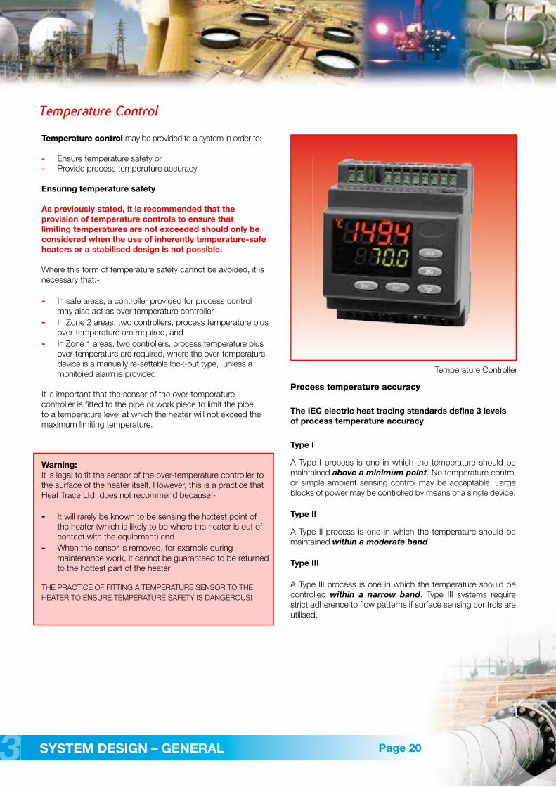
Temperature Controller

Circuit Monitoring
If failure of a heater can result in a safety or process problem, then the heat tracing system may be considered to be critical to the total process. The temperature control and circuit monitoring requirements of an application are defined by the IEC Electric Heat Tracing standards according to the temperature control types as previously described, together with the circuit monitoring criticality as described in the table below.
Process types
When heat tracing is critical to the process, circuit monitoring for correct operation is recommended. Malfunction alarms, and back-up (redundant) heat tracers may also be considered. Spare or back-up controllers can be specified to be automatically activated in the event of a fault being indicated by the monitoring / alarm system. This is sometimes known as “redundancy”. Back-up heat tracers will maintain availability and may allow maintenance or repairs to be performed without a process shutdown.
SYSTEM DESIGN – GENERAL 33
Circuit Monitoring
Page 21
Desired accuracy of process temperature control
Is heat tracing a Maintain Maintain Maintaincritical component above a within a within a
of the process? minimum moderate narrow point Type I band Type II band Type III
Yes = Critical (C) C – I C – II C – III
No = Non-critical (NC) NC – I NC – II NC – III
Temperature Controller with Monitoring

There are four generic types of heat tracer
� Parallel Self-Regulating� Parallel Constant Power
Parallel Self-Regulating
Self-Regulating (or self-limiting) tracers are most popular, as they can conveniently be cut-to-length and are often inherently temperature-safe, due to the positive temperature coefficient heating matrix. Thus temperature control is not usually needed to provide temperature safety.
Until recently, their availability for only low or moderate temperatures limited their use. Now though, Heat Trace Ltd. have pioneered new 3rd generation semi-conductive tracersable to withstand up to 300ºC energised or power off. So now, Self-Regulating tracers can fulfil 90% of all applications within industrial heat tracing – but currently only from Heat Trace!
Ever since the introduction of self-regulating tracers, the high currents on start up from cold have created a problem requiring the need for larger than necessary feed cables and switchgear. Additionally, safety was compromised, as circuit protection had to be sized in excess of operating currents. Now however, Heat Trace has made significant reductions in start currents, thereby improving safety, and reducing distribution costs.
A patented SoftStart device (see illustrations below) having NTC (negative temperature coefficient) characteristics negates the PTC (positive temperature coefficient) of the heating matrix. Start currents are reduced by about 50% (see Figure below). This is further aided by a patented processing method known as Directional Conductivity. Here the conductive particles within the heating matrix are dispersed and distributed in such a way as to control the direction of current flow.
Single phase Self-Regulating tracers are typically limited in circuit length to 100 or 200 metres, and so are used mainly for in-plant applications. However Heat-Trace can now provide the world’s first 3 phase self-regulating tracer capable of circuit lengths upto 600m.
PRODUCTS AND PRODUCT SELECTION44
Heating Cables - Generic types
Page 22
Heat Trace’s range of self regulating heat tracers
Heat Trace Limited is able to produce self-regulating tracers within the following range:
12 - 1000 VoltsUp to 300ºC withstand temperatureUp to 150 W/m
Datasheets for some of the standard Heat Trace range are provided, pages 30 - 35 inclusive
Temperature ranges:
LowFSLe 85ºC On or Off - up to 31W/mFSR 85ºC On or Off - up to 40W/m FSE 100ºC On or Off - up to 60W/m
HIghFS+ 225ºC On or Off - up to 60W/mFSS 225ºC On or Off - up to 75W/mFSU 250ºC On or Off - up to 100W/mFSU+ 275ºC On or Off - up to 125W/mAFS 300ºC On or Off - up to 150W/m
� Series Resistance� Skin-Trace
Temperature
Pow
er O
utpu
t
Inrush Current Trend
Time
Cur
rent
MODIFIED CURVE USINGSOFTSTART DEVICE
TYPICAL IN-RUSH CHARACTERISTICFOR SELF-REGULATING HEATING CABLE
Soft Start Device

PRODUCTS AND PRODUCT SELECTION 44
Heating Cables - Generic types
Page 23
Parallel Constant Power
Parallel Constant Power (zonal) tracers can be conveniently cut-to-length, but are less popular than Self-Regulating heaters, because they often require thermostatic control to ensure temperature safety, (although sometimes a calculated temperature-safe stabilised design is possible).
Until recently, all constant power tracers were polymeric, and so were limited in temperature capability. However, Heat Trace has patented a parallel resistance, convenient cut-to-length metal sheathed, mineral insulated (MI) heater having a withstand temperature of 425 deg. C. This type AHT product caters for most applications that the new high temperature Self-Regulating heaters are unable to handle. Thus cut-to-length parallel tracers are now available for virtually all heat tracing applications.
This is particularly beneficial in the case of instrument lines, the lengths of which are usually unknown at the design stage of a project, and which are site run according to convenience.
Parallel Constant Power tracers are typically limited in circuit length to 100 or 200 metres, and so are used mainly for in-plant applications
Parallel heating zones
Heat Trace’s range of Parallel Constant Power heat tracers
Heat Trace Limited is able to produce tracers within the following limitations
Up to 425ºC withstand temperatureUp to 200 W/m
Datasheets of some of the standard Heat Trace range are provided, pages 36 - 39 inclusive
Temperature ranges:
MediumMTF 200ºC On or Off - up to 50W/mEMTF 200ºC On or Off - up to 50W/m
HighPHT 425ºC On or Off - up to 70W/mAHT 425ºC On or Off - up to 150W/m)
Series Resistance Tracers
Series Resistance Tracers have to be individually designed into particular length/load configurations and so are not so versatile as parallel types.
However, an advantage is that very long circuit lengths are possible – typically 3 phase ‘Longline’ tracers require electric supply points only at multi-kilometre intervals. So the major outlet for series heaters is long pipelines.
Traditionally, metal sheathed, mineral insulated (MI) series cables were used when process temperatures exceeded the capability of the more convenient polymeric parallel tracers. However, the introduction of Heat Trace’s cut-to-length parallel type AHT MI tracer virtually eliminates the need for series MI tracers which require skill to terminate and are costly.
Series Resistance Tracers often require temperature controls to ensure temperature safety.
Heat Trace’s range of series ‘Longline’ heat tracers
Heat Trace Limited is able to produce tracers within the following limitations
Up to 6.6kV Volts 3 phaseUp to 300ºC withstand temperatureUp to 200 W/m of pipe
Datasheets of some of the standard Heat Trace range are provided, pages 40 - 43 inclusive
Temperature ranges
Low Medium HighHTP3 HTS3F HT/A3FHTP1 HTS1F HT/A1F
Longline series resistance tracers are for the heating of very long pipelines, a very competitive option to Skin Trace.
Heating Cables - Generic types
PRODUCTS AND PRODUCT SELECTION44 Page 24
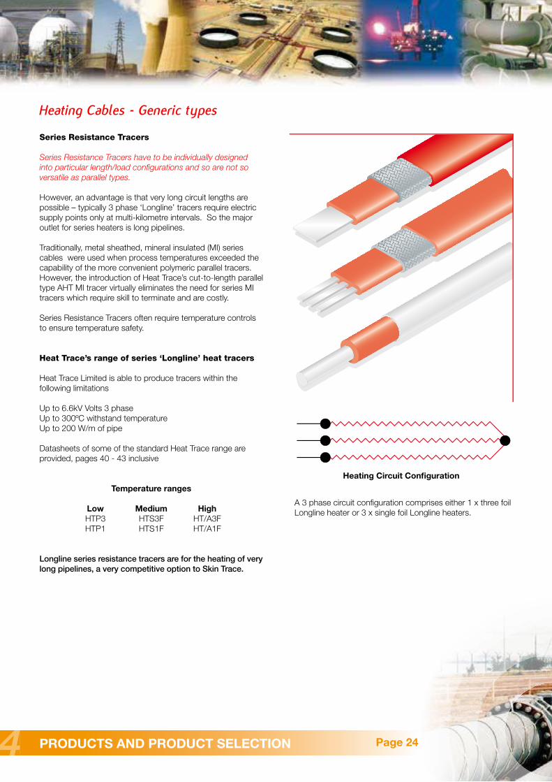
Heating Circuit Configuration
A 3 phase circuit configuration comprises either 1 x three foil Longline heater or 3 x single foil Longline heaters.

Heating Cables - Generic types
Depending on the heating power required and the pipeline length, SKIN-TRACE may consist of either one, two, or three, heater tubes (see image above).
OPERATING TEMPERATURE -40ºC to +200ºC
POWER SUPPLY up to 3kV AC 50 or 60 Hz
POWER OUTPUT
Rated power output of one heating element
Rated Power output of one heater tube, W/m
Heater Tube Dimension
1 40mm2 25mm3 19mm4 10mm
PRODUCTS AND PRODUCT SELECTION 44Page 25
12
34
80
60
40
20
00 2 4 6 8 10 12 14 16 18
L e n g t h o f h e a t e d p i p e l i n e , km
W/m
O u
t p
u t
Skin-Trace
Skin-Trace is induction-resistive heat tracing based on skin and proximity effects of an AC current within a ferromagnetic tube.
The heating element comprises a carbon steel tube into which is inserted an insulated non-magnetic conductor. The conductor and the steel tube are connected together at one end. At the other end an AC voltage is applied between the conductor and the tube. The relationship of conductor/tube sizes and voltage determines the output power developed.
The skin effect of the magnetic tube results in the current being concentrated towards the tube’s inner surface, the potential to the outside being zero.
Skin-Trace’s advantage is that long circuit lengths are possible – typically a pipeline of up to 20km may be heated from a single electric supply point. So Skin-Trace is most appropriate for the heating of cross-country pipelines.
� Typically up to 20 km lines heated from one supply point
� Robust and reliable system with outputs up to 120W/m
� Suitable for up to 200ºC operating temperature
� Suitable for use in hazardous areas
SKIN-TRACEheater tube
Pipe wall
Heat�ow

� In-plant areas
Heat tracers for in-plant areas are usually selected according to the maximum temperature to which the tracer will be subjected, and the power output required from the tracer.
The following table shows the relationship between temperature withstand and power output for various self-regulating, constant power, and series MI tracers. It may be seen that self-regulating tracers, which can be conveniently cut-to-length and which are usually temperature-safe, are available for exposure temperatures up to 300ºC.
AHT constant power tracers can cater for higher exposure temperatures up to 425ºC and high power outputs up to 150W/m.
Only exceptionally is it necessary to employ series MI cables, which must be specifically designed for a particular length and output.
PRODUCTS AND PRODUCT SELECTION44
Heating Cables – Selection Guide
Page 26
Stainless steel sheathedMI Series Type
AHT
FSU
FSU+
FSS
FS+FSE
FSR
FSLe
AFS
50 100 150 200 250 300 350 400 450 500 550 600
0
25
50
75
100
125
150
175
200
0
Withstand Temperature °C
Wat
ts/m
Parallel / Self Regulating Parallel Constant Power Series Resistance M.I.
Cut to length Speci�c design factory fabricated
Temperature Capability (typical)

PRODUCTS AND PRODUCT SELECTION 44
� Transfer and long pipe runs
Until recently, parallel resistance heaters – self-regulating or constant power – were limited by volt drop to around 150 metres circuit length.
Now, Heat Trace’s patented 3 phase self-regulating tracer, particularly when connected to an elevated voltage e.g. 600 volts, is capable of circuit lengths of up to 700 metres. Consequently, inherently temperature-safe heating systems are now available for applications previously not possible.
Beyond 700 metres, it is necessary to select series resistance 3 phase Longline heating cables, which have a capability to, for example 5km.
For very long pipe runs, e.g. >10km from a single electrical supply point, there was, until recently, no alternative to the Skin-Trace, skin-effect heating system. However, Heat Trace’s new continuous metal extrusion facility has enabled Longlinesystems to heat up to 50km of pipe from a single electrical feed point.
The advantages of the Longline system over Skin-Trace are:-
� Lower capital cost
� Cheaper/ simpler installation
� Lower operating costs (Skin-Trace power factor is 0.85 against the unity factor of Longline)
Heating Cables – Selection Guide
Page 27
Circuit Length (typical) - MetresSingle PhaseSelf Regulating/
Parallel ConstantWattage
3 Foil Longline
Skin Trace
0 1500m200m 600m 60,000m20,000m
Self Regulating3 Phase
3 x 1 Foil Longline

PRODUCTS AND PRODUCT SELECTION44 Page 28
Heater selection is usually governed by the pipe length. Some interesting selections and applications are:-
‘Downhole’ oilwells
In these, oil exits the reservoir into the production tube at high temperature, cooling as it rises to the surface. To prevent the oil temperature falling below its pour point where waxing can occur on the walls of the production tube, the upper sections of the tube may be heated.
In ‘Downhole’ applications of heated depths to 700 metres, the benefits of inherently temperature-safe self-regulating heaters are preferred. The principle of self-regulating is attractive, because progressively more heat is produced as the oil rises towards the surface, cools, and the temperature falls. In the past this has not been feasible, but Heat Trace have developed the world’s first self-regulating 3 phase heater, a patented product based on it’s unique phase-balanced load design.
Typical Long Pipeline Applications
Heater Power SupplyOil Flow
Well Head
3 Phase Self-RegulatingHeating Cable withContinuous Metal Jacket
Downhole Heater
Production Tube
Heater PowerTermination
Heater Power Supply Cable
3 Phase Constant PowerHeating Cable withContinuous Metal Jacket
In another well, requiring heating down to 2km, a unique Heat Trace Longline product can be provided with heating conductors whose power output varies from point to point along the pipe route within a single heating cable. Heat Trace’s conductor extrusion facility is able to vary it’s cross-section, and hence the power output, at will in a continuous extruded length.
Long Pre-insulated PipelinesThe picture below shows a typical long pipeline application where a pre-insulated pipeline is fitted with an HTS3F-CS LONGLINE series resistance heating cable. The pre-insulated pipe is constructed with a metal “raceway” during construction. The heating cable is pulled through the raceway on site as the pre-fabricated pipe lengths are joined together at site, prior to being buried. The pipeline was carrying crude oil from the on-land oil well to a central gathering station.
Skin Effect Heat TracingThe picture below shows a completed skin effect tracing system prior to being buried. Skin effect tracing systems may be employed for very long cross-country pipelines. Skin trace is an inductive heating system and may be used for pipelines of up to 30km circuit lengths from a single power supply.
Buried, Pre-insulated Pipe with Longline HTS3F
Completed Skin Trace system prior to burying

PRODUCTS AND PRODUCT SELECTION 44Page 29
Off-shore Applications
In-shore Applications
Subsea pipelines for in-shore applications are also used extensively around the world. A typical application might be a fuel tanker off-loading facility for an on-shore plant or power station. These systems are generally run from the on-shore plant storage tank, across the shore line and out to a PLEM located on the seabed and attached to a CALM buoy. The subsea section of the pipe can vary, usually between 1 - 3km from the shore, depending on the depth of water. The pipelines for these applications generally use pre-insulated pipe sections fitted with raceways for the heating cables. These sections are joined together on-shore and the completed pipeline floated/towed into position prior to sinking to the seabed. Alternatively, the pipe sections can be assembled and laid from a barge. Due to the shallow water, these pipelines are usually laid in a trench, or protected in some way, such as a “rock dump”.
Off-shore Applications
As one of the world’s leading suppliers of electric heat tracing products, Heat Trace Limited (HTL) can provide a wide range of heaters and ancillary products that are particularly suited to offshore applications.
In the harsh off-shore environment, safety and reliability are high priorities and HTL is able to supply high quality products and services to meet the demands of the industry. Heaters for subsea pipelines and risers, topside pipeline heating for both freeze protection and temperature maintenance, helicopter platform snow and ice prevention systems, under-floor heating for accommodation - these are just some of the application solutions available from Heat Trace Limited.
Subsea Pipeline Heating
Heat Trace’s ‘Longline’ heating system has recently been installed on the world’s first reelable heat traced, subsea pipe-in-pipe for a 6.5km gas condensate pipeline, using 75km of heating conductors produced by our new continuous metal extrusion facility. The 2kV system is capable of maintaining the required pipeline temperatures from a single electrical supply point in a 3 phase balanced load configuration by a single heating cable. Temperature control and system monitoring is achieved through the use of fibre optic cables installed with the heaters on the inner production flowline. At the time of writing, several other larger subsea installations, for pipelines up to 50km in length, are in the process of being designed. Heat Trace’s heat tracing system for pipe-in-pipe systems are suitable for relatively shallow water applications of around 80-100m depth or for deep sea applications down to 2500 - 3000 metres.
FOR FURTHER INFORMATION ON LONG PIPELINE HEATING SYSTEMS PLEASE VISIT OUR WEBSITE AND READ THE ARTICLE ABOUT “ ELECTRIC HEAT TRACING OF LONG PIPELINES “
www.heat-trace.com
Typical subsea tie back from well head to production platform
Completed electrically heat-traced pipe-in-pipe being reeled onto the pipelay vessel.
Helicopter platform, ice prevention systems

PRODUCTS AND PRODUCT SELECTION44 Page 30
Product Data - Parallel Self-Regulating Heaters to 100°C
FREEZSTOP - Low Temperature RangeSelf-Regulating Heating Cables for exposuretemperatures up to 100°C
A versatile range of industrial grade self-regulating heating cables for freeze protection and low process temperature maintenance duties. All cables are available with a choice of flexible metallic braid or continuous metallic extruded jacket. Further corrosion resisting overjacket in thermoplastic or fluoropolymer is optional. Approved for use in both safe and hazardous areas. Available for voltages 100 – 120VAC and 208 – 277VAC.
FREEZSTOP EXTRAFSE withstand temperatures - 100°C energised / 100°C un-energised.
FREEZSTOP LITEFSLe withstand temperatures - 85°C energised / 85°C un-energised.
FREEZSTOP REGULARFSR withstand temperatures - 85°C energised / 85°C un-energised.
Low
Tem
pera
ture
Buswires
Semi-conductive self-limiting matrix
Thermoplastic elastomer insulation
Metallic braid or continuous metal jacket
Overjacket ( optional )
� Use Type C or D motor rated circuit breakers� Maximum circuit lengths are based on a start
up temperature of 10ºC� If circuits are started up when heaters are below
10ºC, circuit breakers may trip. If this happens, re-energise the circuits until the heaters warm up, and circuit breakers remain switched on
� For maximum circuit lengths for start up temperatures below 10ºC, please consult Heat Trace Limited
� THERMAL RATINGSNominal power output at 115V or 230V when installed on insulated metal pipes.
FREEZSTOP MICROFSM withstand temperatures - 65°C energised / 85°C un-energised.

PRODUCTS AND PRODUCT SELECTION 44Page 31
Product Data - Parallel Self-regulating Heaters to 100°C
MICRO - FSM Specification Data MAXIMUM LENGTH (m) vs. CIRCUIT BREAKER SIZECat 115V 230VRef 6A 16A 6A 16A
11FSM 38 64 76 128
17FSM 27 51 54 102
LITE - FSLe Specification Data MAXIMUM LENGTH (m) vs. CIRCUIT BREAKER SIZECat 115V 230VRef 10A 16A 20A 10A 16A 20A
12FSLe 38 90 - 132 180 -
17FSLe 31 73 - 104 146 -
23FSLe 23 62 - 76 124 -
31FSLe 17 46 51 58 92 102
REGULAR - FSR Specification DataMAXIMUM LENGTH (m) vs. CIRCUIT BREAKER SIZECat 115V 230VRef 16A 20A 25A 16A 20A 25A
10FSR 99 - - 198 - -
17FSR 77 - - 154 --25FSR 62 - - 124 --31FSR 37 46 55 74 92 110
40FSR 28 35 44 56 70 88
Extra - FSE Specification DataMAXIMUM LENGTH (m) vs. CIRCUIT BREAKER SIZECat 115V 230VRef 16A 20A 25A 16A 20A25A17FSE 60 74 - 120 148-31FSE 41 55 - 82 104 110
45FSEw 31 38 48 62 76 96
60FSEw 26 33 41 52 6682
0 5 10 15 20 25 30 35 40 45 50 55 60 65 70 75 80 85
5
10
15
20
25
30
35
40
45
50
55
60
65
70
90 95 100
17
31
45
60
Pipe Temperature (ºC)
W/m
0 5 10 15 20 25 30 35 40 45 50 55 60 65 70 75 80 85
5
10
15
20
25
30
35
12
17
23
31
Pipe Temperature (ºC)
W/m
0 5 10 15 20 25 30 35 40 45 50 55 60 65 70 75 80 85
5
10
15
20
25
30
35
40
45
10
17
25
31
40
Pipe Temperature (ºC)
W/m
Low
Tem
pera
ture
FULL TECHNICAL DATA SHEETS ARE AVAILABLE ON OUR WEBSITE FOR ALL PRODUCTSwww.heat-trace.com
Pipe Temperature (ºC)
W/m
0 5
5
10
15
20
25
10 15 20 25 30 35 40 45 6050 55 65
17
11

PRODUCTS AND PRODUCT SELECTION44 Page 32
Product Data - Parallel Self-Regulating Heaters to 250°C
FAILSAFE - High Temperature Range Self-Regulating Heating Cables for exposuretemperatures up to 250°C
A versatile range of industrial grade self-regulating heating cables for freeze protection and high process temperature maintenance duties. All cables are available with a choice of flexible metallic braid or continuous metallic extruded jacket. Further corrosion resisting overjacket in silicone rubber or fluoropolymer is optional. Approved for use in both safe and hazardous areas. Available for voltages 100 – 120VAC and 208 – 277VAC.
FAILSAFE +FS+ withstand temperatures - 225°C energised / 225°C un-energised.
FAILSAFE SUPERFSS withstand temperatures - 225°C energised / 225°C un-energised.
Hig
h T
em
pera
ture
Buswires
Semi-conductive self-limiting matrix
Insulation
Metallic braid orcontinuous metal Jacket
Overjacket ( optional )
� Use Type C or D motor rated circuit breakers� Maximum circuit lengths are based on a start up
temperature of 10ºC� If circuits are started up when heaters are below
10ºC, circuit breakers may trip. If this happens, re-energise the circuits until the heaters warm up, and circuit breakers remain switched on
� For maximum circuit lengths for start up temperatures below 10ºC, please consult Heat Trace Limited
� THERMAL RATINGSNominal power output at 115V or 230V when installed on insulated metal pipes.
FAILSAFE ULTIMOFSU withstand temperatures - 250°C energised / 250°C un-energised.

PRODUCTS AND PRODUCT SELECTION 44Page 33
Product Data - Parallel Self-regulating Heaters to 250°C
FAILSAFE + Specification DataMAXIMUM LENGTH (m) vs. CIRCUIT BREAKER SIZECat 115V 230VRef 20A 25A 32A 20A 25A32A
15FS+ 77 - - 154 - -
30FS+ 51 - - 102 - 108
45FS+ 38 - 44 76 - 88
60FS+ 31 - 38 62 - 76
FAILSAFE SUPER Specification DataMAXIMUM LENGTH (m) vs. CIRCUIT BREAKER SIZECat 115V 230VRef 20A 25A 32A 20A 25A 32A
15FSS 77 - - 154 - -
30FSS 51 55 54 102 110 108
45FSS 30 38 48 60 76 96
60FSS 26 33 41 52 66 82
75FSS 26 33 41 52 66 82
FAILSAFE ULTIMO Specification DataMAXIMUM LENGTH (m) vs. CIRCUIT BREAKER SIZECat 115V 230VRef 20A 25A 32A 20A 25A 32A
15FSU 77 - - 154 - -
30FSU 51 55 - 102 110 -
45FSU 30 38 48 76 76 96
60FSU 26 31 41 62 62 82
75FSU 26 33 41 46 66 82
100FSUw 26 33 41 30 66 82
0 20
10
20
30
40
50
60
70
40 60 80 100 120 140 160 180 200 220
80
15
30
45
60
75
Pipe Temperature (ºC)
W/m
0 20
10
20
40
30
50
60
70
40 60 80 100 120 140 160 180 200
15
30
45
60
Pipe Temperature (ºC)
W/m
Hig
h T
em
pera
ture
FULL TECHNICAL DATA SHEETS ARE AVAILABLE ON OUR WEBSITE FOR ALL PRODUCTSwww.heat-trace.com
0 20
15
30
45
60
75
90
105
40 60 80 100 120 140 160 180 200 220 240
15
30
45
60
75
100
Pipe Temperature (ºC)
W/m

PRODUCTS AND PRODUCT SELECTION44 Page 34
Product Data - Parallel Self-Regulating Heaters to 300°C
FAILSAFE - Ultra High Temperature Range Self-Regulating Heating Cables for exposuretemperatures up to 300°C
A versatile range of industrial grade self-regulating heating cables for freeze protection and ultra high process temperature maintenance duties.All cables are available with a continuous extruded patented metal coating for earth protection and mechanical strength and optionally with a fluoropolymer outer jacket. Approved for use in both safe and hazardous areas. Available for voltages from 12 – 1000V ( AC or DC ).
FAILSAFE ULTIMO+FSU+ withstand temperatures - 275°C energised / 275°C un-energised.
AUTO FAILSAFEAFS withstand temperatures - 300°C energised / 300°C un-energised.( reduced to 275ºC when overjacketis provided ).
Very
Hig
h T
em
pera
ture
Buswires
Semi-conductive self-limiting matrix
Electrical insulation
Continuous conductivemetal jacket
Overjacket ( optional )
� Use Type C or D motor rated circuit breakers
� Maximum circuit lengths are based on a start up temperature of 10ºC
� If circuits are started up when heaters are below 10ºC, circuit breakers may trip. If this happens, re-energise the circuits until the heaters warm up, and circuit breakers remain switched on
� For maximum circuit lengths for start up temperatures below 10ºC, please consult Heat Trace Limited
� THERMAL RATINGSNominal power output at 115V or 230V when installed on insulated metal pipes.

PRODUCTS AND PRODUCT SELECTION 44Page 35
Product Data - Parallel Self-regulating Heaters to 300°C
ULTIMO - FSU+ Specification Data MAXIMUM LENGTH (m) vs. CIRCUIT BREAKER SIZECat 115V 230VRef 20A 32A 20A 32A
15FSU+ 77 - 154 -
30FSU+ 51 54 102 108
45FSU+ 38 44 76 88
60FSU+ 31 38 62 76
75FSU+ 23 34 46 68
100FSU+w 15 25 30 50
125FSU+w 10 10 20 20
AUTO - AFS Specification DataMAXIMUM LENGTH (m) vs. CIRCUIT BREAKER SIZECat 115V 230VRef 20A 40A 63A 20A 40A 63A
15AFS 77 98 - 154 196 -
30AFS 46 69 - 92 138 -
50AFS 31 49 54 62 98 108
75AFS 23 37 44 46 74 88
100AFS 15 25 38 30 50 76
125AFS 10 15 30 20 30 60
150AFS 7 11 21 14 22 42
0 20
10
20
30
40
50
60
70
80
90
100
110
120
130
140
150
40 60 80 100 120 140 160 180 200 220
15
30
50
75
100
125
150
Pipe Temperature (ºC)
W/m
0 20
15
30
45
60
75
90
105
120
40 60 80 100
Pipe Temperature (ºC)
W/m
120 140 160 180 200 220 240
15
30
45
60
75
100
125
Very
Hig
h T
em
pera
ture
FULL TECHNICAL DATA SHEETS ARE AVAILABLE ON OUR WEBSITE FOR ALL PRODUCTSwww.heat-trace.com

PRODUCTS AND PRODUCT SELECTION44
Product Data - Parallel Constant Power Heaters to 200°C
Page 36
MINITRACER - Low to Medium Temperature Range Parallel Constant Power Heating Cables for exposure temperatures up to 200°C
Types MTF and EMTF are parallel resistance, constant wattage, cut-to-length heating cables that can be used for freeze protection or low to medium process heating of pipe work and vessels. They can be cut to length at site and easily terminated. Suitable for use in both safe and hazardous areas. MTF and EMTF heaters are available with metallic braid, or braid and fluoropolymer outer jacket.As an alternative to the braid, a continuous metal jacket can be provided for additional mechanical protection.
Available for 100/120 and 208/240VAC. Installation of the heating cables is quick and simple and requires no special skills or tools. Termination and power connection components are all provided in convenient kits.
MINITRACER
MICROTRACER
Low
- M
ediu
m T
em
pera
ture
Copper Buswires
Silicone Rubber Insulation
Parallel Circuit ConnectionMetal Sprayed Joint
Heating Element
Fluoropolymer Jacket
Metallic Braid or ContinuousMetal Jacket.
Overjacket ( optional )

PRODUCTS AND PRODUCT SELECTION 44
Product Data - Parallel Constant Power Heaters to 200°C
Page 37
MAXIMUM PIPE / WORKPIECE TEMPERATURES (°C)CAT NOM. AREA CLASSIFICATIONREF OUTPUT HAZARDOUS
(W/m) T6 T5 T4 T3 T2 T1 SAFEMTF..C 6.5 60 75 120 190 190 190 190MTF..A 13 40 55 95 175 180 180 180
23 - 30 65 155 155 155 15533 - - 40 115 120 120 12050 - - - 70 80 80 80
MTF..CF 6.5 60 80 125 190 190 190 190MTF..AF 13 35 50 100 185 185 185 185
23 - 25 55 160 165 165 16533 - - 35 115 120 120 12050 - - - 80 85 85 85
MTF Specification DataMAXIMUM LENGTH (m) vs. CIRCUIT BREAKER SIZE
OUTPUT MAX. CIRCUIT LENGTH*(W/m) 115V 230V
6.5 106 21213 75 15023 56 11333 47 9450 38 76
* For ±10% end to end power output variation
MAXIMUM PIPE / WORKPIECE TEMPERATURES (°C)NOM.
OUTPUT EMTF-C EMTF-CF(W/m) EMTF-A EMTF-AF
6.5 190 19013 175 18523 145 15533 100 10050 60 70
EMTF Specification DataMAXIMUM LENGTH (m) vs. CIRCUIT BREAKER SIZE
OUTPUT MAX. CIRCUIT LENGTH*(W/m) 115V 230V
6.5 82 16413 58 11623 44 8733 36 7350 30 59
* For ±10% end to end power output variation
Low
- M
ediu
m T
em
pera
ture
POWER CONVERSION FACTORS
115V HEATING CABLE 230V HEATING CABLE125V Multiply output by 1.18 277V Multiply output by 1.45120V Multiply output by 1.09 240V Multiply output by 1.09110V Multiply output by 0.91 220V Multiply output by 0.91100V Multiply output by 0.76 208V Multiply output by 0.82
For conditions other than worst case, or pipes of other materials (eg. plastic, stainless steel, etc..), consult Heat Trace Ltd. Tolerances: Voltage +10%; Resistance +10%; -0%
FULL TECHNICAL DATA SHEETS ARE AVAILABLE ON OUR WEBSITE FOR ALL PRODUCTSwww.heat-trace.com

PRODUCTS AND PRODUCT SELECTION44 Page 38
Product Data - Parallel Constant Power Heaters to 425°C
POWERHEAT - High Temperature Range Parallel Constant Power Heating Cables for exposure temperatures up to 425°C
Powerheat range PHT and AHT are parallel circuit, mineral insulated, cut-to-length, constant power heating cables. They are used for freeze protection and process heating of pipe work and vessels, where very high withstand temperatures, or where high power outputs are required. Their cut-to-length capability means they can be easily terminated at site. They are suitable for use in both safe and hazardous areas.
Powerheat cables are insulated with multiple layers of non-hygroscopic mineral materials to withstand high temperatures. PHT is available with a metallic braid, or braid and fluoropolymer outer jacket. AHT cables have an aluminium outer jacket, giving a high mechanical strength, yet still retaining flexibility. Available for 100/120 and 208/277VAC.
POWERHEAT - PHTWithstand Temperature up to 285°C
POWERHEAT - AHTWithstand Temperature up to 425°C
Hig
h T
em
pera
ture
Copper Buswires
Non-Hygroscopic mineralInsulation
Non-Hygroscopic mineralInsulation
Heating Element
Parallel Circuit ConnectionMetal Sprayed Joint
Non-Hygroscopic mineralInsulation
Aluminium Jacket
Type AHT

PRODUCTS AND PRODUCT SELECTION 44Page 39
Product Data - Parallel Constant Power Heaters to 425°C
MAXIMUM PIPE / WORKPIECE TEMPERATURES (°C)CAT NOM. AREA CLASSIFICATIONREF OUTPUT HAZARDOUS
(W/m) T6 T5 T4 T3 T2 T1 SAFEPHT..N 10 44 61 102 180 275 275 275
30 - - 24 116 246 246 24650 - - - 48 200 200 20070 - - - - 144 144 144
PHT..NF 10 40 60 105 186 275 275 27530 - - 22 132 255 255 25550 - - - 63 215 215 21570 - - - - 168 168 168
PHT Specification DataMAXIMUM LENGTH (m) vs. CIRCUIT BREAKER SIZE
OUTPUT MAX. CIRCUIT LENGTH*(W/m) 115V 230V
10 79 15230 46 8850 35 6870 30 56
* For ±10% end to end power output variation
MAXIMUM PIPE / WORKPIECE TEMPERATURES (°C)CAT NOM. AREA CLASSIFICATIONREF OUTPUT HAZARDOUS
(W/m) T6 T5 T4 T3 T2 T1 SAFEAHT 15 - 36 71 160 289 350 350
30 - 11 28 100 246 323 32350 - - - 39 178 276 276
100 - - - - 48 140 140150 - - - - - 36 36
AHT Specification DataMAXIMUM LENGTH (m) vs. CIRCUIT BREAKER SIZE
OUTPUT MAX. CIRCUIT LENGTH*(W/m) 115V 230V
15 59 11830 42 8350 32 64100 23 46150 19 37
* For ±10% end to end power output variation
Hig
h T
em
pera
ture
POWER CONVERSION FACTORS
115V HEATING CABLE 230V HEATING CABLE125V Multiply output by 1.18 277V Multiply output by 1.45120V Multiply output by 1.09 240V Multiply output by 1.09110V Multiply output by 0.91 220V Multiply output by 0.91100V Multiply output by 0.76 208V Multiply output by 0.82
For conditions other than worst case, or pipes of other materials (eg. plastic, stainless steel, etc..), consult Heat Trace Ltd. Tolerances: Voltage +10%; Resistance +10%; -0%
FULL TECHNICAL DATA SHEETS ARE AVAILABLE ON OUR WEBSITE FOR ALL PRODUCTSwww.heat-trace.com

PRODUCTS AND PRODUCT SELECTION44 Page 40
Product Data - Series Resistance Heaters to 125°C
LONGLINE - Low Temperature Range Series constant power heating cables for long pipelines. Exposure temperatures up to 125°C
Longline HTP3F and HTP1F are series resistance, constant power heating cables used for freeze protection, or, process temperature maintenance of long pipelines where low temperatures are encountered.
HTP3F cables are used typically for pipelines up to 2km between supply points. HTP1F cables are used where there is approx 10km between supply points.
Longline series heating cables minimise the number of electrical supplies needed and so minimise supply cabling / distribution equipment costs. Circuits are often fed at the pipe ends only. All cables are available with a choice of flexible metallic braid or continuous metallic extended jacket. A further corrosion resisting overjacket in thermoplastic or fluoropolymer is optional.This style of cable is specifically designed to suit each application. The output of the heater is a function of the circuit length, the size of the conductor foils and the supply voltage.
Longline is an extremely viable option to skin effect heating for very long pipelines.
LONGLINE - HTP3F
LONGLINE - HTP1F
Low
Tem
pera
ture
Metal Heating
Foil Conductor
Primary Insulation
Thermoplastic elastomer
Metallic braid or
Continuous Metal Jacket
Overjacket ( optional )

PRODUCTS AND PRODUCT SELECTION 44Page 41
Product Data - Series Resistance Heaters to 125°C
HTP3F Specification DataMAXIMUM PIPE / WORKPIECE TEMPERATURES (°C)
NOM. OUTPUT(W/m) HTP3F-C HTP3F-CT/CF
HTP3F-A HTP3F-AT/AF10 109 10015 95 8523 80 70
For conditions other than worst case, or pipes of other materials (eg. plastic, stainless steel, etc..), consult Heat Trace Ltd.
Tolerances: Voltage +10%; Resistance +10%; -0%
HTP1F Specification DataMAXIMUM PIPE / WORKPIECE TEMPERATURES (°C)
NOM. OUTPUT(W/m) HTP1F-C HTP1F-CT/CF
HTP1F-A HTP1F-AT/AF10 109 10015 95 8523 80 70
For conditions other than worst case, or pipes of other materials (eg. plastic, stainless steel, etc..), consult Heat Trace Ltd.
Tolerances: Voltage +10%; Resistance +10%; -0%
Low
Tem
pera
ture
FULL TECHNICAL DATA SHEETS ARE AVAILABLE ON OUR WEBSITE FOR ALL PRODUCTSwww.heat-trace.com
Typical Longline applications for heating of pre-insulated pipe work with heaters in raceways.
3 Foil Longline heater
3 x Single FoilLongline heater

PRODUCTS AND PRODUCT SELECTION44
Product Data - Series Resistance Heaters - 230°C
Page 42
LONGLINE - Medium Temperature Range Series constant power heating cables for long pipelines. Exposure temperatures up to 230°C
Longline HTS3F and HTS1F are series resistance, constant power heating cables with silicone insulation, used for freeze protection, or process temperature maintenance of long pipelines where medium temperatures are encountered.
HTS3F cables are used generally for long pipelines up to 2km between supply points.
HTS1F cables are typically used where there is approx up to 10km between supply points. Longline series heating cables minimise the number of electrical supplies needed and so minimises supply cabling / distribution equipment costs. Circuits are often fed at the pipe ends only. All cables are available with metallic braid, braid and silicone rubber jacket, or braid and fluoropolymer jacket.This style of cable is specifically designed to suit each application. The output of the heater is a function of the circuit length, the size of the conductor foils and the supply voltage.Longline is an extremely viable option to skin effect heating for very long pipelines.
LONGLINE - HTS3F
LONGLINE - HTS1F
Mediu
m T
em
pera
ture
Metal Heating
Foil Conductor
Primary Insulation
Silicone Rubber
Metallic braid or
Continuous Metal Jacket
Overjacket ( optional )

PRODUCTS AND PRODUCT SELECTION 44
Product Data - Series Resistance Heaters - 230°C
Page 43
HTS1F Specification DataMAXIMUM PIPE / WORKPIECE TEMPERATURES (°C)NOM. OUTPUT
(W/m) HTS1F-C HTS1F-CS HTS1F-CF-A -AS -AF
10 218 208 19220 191 180 17830 164 158 16540 134 127 12750 97 93 9360 46 57 57
For conditions other than worst case, or pipes of other materials (eg. plastic, stainless steel, etc..), consult Heat Trace Ltd.
Tolerances: Voltage +10%; Resistance +10%; -0%
HTS3F Specification DataMAXIMUM PIPE / WORKPIECE TEMPERATURES (°C)CAT NOM. AREA CLASSIFICATIONREF OUTPUT HAZARDOUS
(W/m) T6 T5 T4 T3 T2 T1 SAFEHTS3F-C 10 48 66 107 181 218 218 218
-A 20 – 32 75 158 191 191 191 30 – – 41 133 164 164 164 40 – – – 109 134 134 134 50 – – – 76 97 97 97 60 – – – 30 46 46 46HTS3F-CS 10 58 74 112 181 208 208 208
-AS 20 37 54 94 166 180 180 180 30 – 31 74 153 158 158 158 40 – – 51 127 127 127 127 50 – – 27 93 93 93 93 60 – – – – – – 57HTS3F-CF 10 58 74 112 181 192 192 192
-AF 20 37 54 94 166 178 178 178 30 – 31 74 153 165 165 165 40 – – 51 127 127 127 127 50 – – 27 93 9 3 93 93 60 – – – – – – 57
For conditions other than worst case, or pipes of other materials (eg. plastic, stainless steel, etc..), consult Heat Trace Ltd.
Tolerances: Voltage +10%; Resistance +10%; -0%
Mediu
m T
em
pera
ture
FULL TECHNICAL DATA SHEETS ARE AVAILABLE ON OUR WEBSITE FOR ALL PRODUCTSwww.heat-trace.com

Terminations – power end
Heat Trace have three different methods for the termination of its parallel heat tracers at the power supply. All methods are available for both safe and hazardous locations:-
� Direct Entry Sealed Termination Unit (DESTU) – This is an improved method, where the junction box is connected to the DESTU, which is mounted onto the pipe surface. The tracer passes through the DESTU into the junction box, avoiding the possibility of damage to the tracer where it exits the thermal insulation.
� StripFree Unit – The StripFree connection box has been specially developed by Heat Trace to reduce installation time and component costs. Tracers can be terminated without the need to strip the ends of self-regulating tracers. StripFree units are available for connection to the power supply and also for series and tee connections. StripFree boxes are particularly useful for small diameter instrument lines which cannot support large junction boxes.
� Standard Method – This uses tracer termination gland components and a junction box. To avoid the possibility of damage to the tracer where it exits from the thermal insulation, a separate lagging entry kit is required.
PRODUCTS AND PRODUCT SELECTION44
Termination Components
Page 44
DESTU
StripFree
StandardGlanded Method

PRODUCTS AND PRODUCT SELECTION 44
Terminations – remote end
Heat Trace have three different methods for the termination of its parallel heat tracers at the remote end. All methods are available for both safe and hazardous locations:-
� Moulded end seal – The silicone rubber end seal is fixed with an adhesive. It is a simple and low cost form of sealing.
� StripFree end seal – The StripFree end seal has been specially developed by Heat Trace to reduce installation time. The end of the tracer is simply pushed into the end seal which immediately seals. It cannot be removed without a tool, and therefore provides additional safety. This seal is considered to be the best form of end-sealing.
� Heat Shrink seal – The fitting of shrink seals require the use of a hot air gun. This may not be practical in a hazardous area.
Termination Components
Page 45
FULL TECHNICAL DATA SHEETS ARE AVAILABLE ON OUR WEBSITE FOR ALL PRODUCTSwww.heat-trace.com
Moulded Endseal
StripFree
Heatshrink Endseal

The selection of an appropriate temperature control system is dictated by its purpose or objective. This guide to selection considers two forms of control:-
• Air-sensing, where the air temperature is monitored and the heating load is either:
a) fully applied at a set temperature, as traditionally used for freeze protection installations, or,
b) varied with changes in ambient temperature, and hence heat losses (called PowerMatching).
• Pipe or surface sensing, where the controller sensor is located directly on the pipe or equipment surface. This method has been traditionally employed for all temperature maintenance duties.
The purpose or objective of the temperature control system may be any one or more of the following:-
1. Ensuring temperature safety
It has already been stated in Section 2 (page 12) that temperature control to ensure temperature safety is the least favoured option – inherently temperature safe self-regulating heaters, or a stabilised design provide greater safety. But where necessary for ensuring temperature safety, pipe or surface sensing is almost always required. Care is required to ensure that all pipes which can experience differing flow conditions are controlled independently – this may result in a large number of heating circuits.
2. Process temperature accuracy
The three levels of process temperature accuracy defined in IEC heat tracing standards, types I, II, and III, are explained in Section 3 (page 18). The approach to selecting the best control system for each type of process is described on page 47.
PRODUCTS AND PRODUCT SELECTION44
TEMPERATURE CONTROL – Selection Guide
Page 46
3. Energy efficiency
The highest levels of energy efficiency have usually required a pipe or surface sensing form of control system. This again often results in multiple heating circuits to accommodate the many permutations of flow conditions. In this case, sections of pipe having differing flow conditions need to be controlled independently.
The degree of energy efficiency is also influenced by the accuracy of the controller – electronic devices are often more accurate than mechanical types.
4. Low capital costs
The lowest capital costs will usually result from a temperature control system having the fewest number of heating circuits. This is normally achieved by an air-sensing form of temperature control system.

Type III process control – maintaining within a narrow temperature band
To control all sections of a piping system within a narrow temperature band of 2ºC, as required for temperature sensitive materials (e.g. chocolate), has traditionally required the use of numerous high accuracy electronic controllers, controlling several sections of pipe which may have differing flow conditions. This has necessarily been provided at a high capital cost.
However, Type III process temperature accuracy can now be achieved with the same PowerMatching control system described for Type II systems above, but with the addition of a fine tuning temperature control.
Again, the heating load delivered at any time is matched to losses according to the ambient conditions. To ensure a narrow band process accuracy, a further sensor is located on a short heated ‘dummy’ line incorporated into the piping system.
SUMMARYType I process control – maintaining above a minimum temperature level
- is very energy wasteful. Not recommended – upgrade to Type II process control
Type II process control – maintaining within a broad temperature band
- can be achieved by air-sensing PowerMatch control to provide good energy efficiency from the fewest number of heating circuits i.e. least capital cost
Type III process control – maintaining within a narrow temperature band
- can be achieved by air-sensing PowerMatch control plus fine-tune line control to provide good energy efficiency from the fewest number of heating circuits.
PRODUCTS AND PRODUCT SELECTION 44
TEMPERATURE CONTROL – Selection Guide
Page 47
Type I process control – maintaining above a minimum temperature level
It should be recognised that a Type I control system will be extremely energy wasteful. For example, a freeze protection installation controlled by an air-sensing thermostat will be 100% energised at all times when the ambient temperature falls below the thermostat setting (typically 2 or 3ºC). However, the average heating requirement over the number of winter hours that the system is energised is likely to be less than 20%, i.e. over 80% of the delivered heat will be wasted.
Most of this waste heat can be avoided by upgrading the system to a Type II process, achieved at a very modest cost, where energy savings recover the additional cost in a very short period of time.
FOR THIS REASON, HEAT TRACE RARELY RECOMMEND ATYPE I TEMPERATURE CONTROL SYSTEM.
Type II process control – maintaining within a broad temperature band
This has traditionally been achieved by means of mechanical capillary thermostats, having their sensors located on the pipe surface.
However, in-plant piping systems are often complex, having multiple flow permutations. To control all possible permutations, a separate thermostat is required for each section of pipe having differing flow conditions. This results in many heating circuits within an expensive distribution system.
To meet the requirements of a Type II process, whilst at the same time reducing to a minimum the number of heating circuits, and hence, distribution and control panel costs, Heat Trace is able to recommend a heat tracing system where:-
a) the tracers are spiralled to the pipes to just compensate for heat losses at the minimum ambient design temperature.
b) the controller is Heat Trace’s unique PowerMatch unit. This monitors the ambient temperature and varies the heat delivered by the tracer according to changes in ambient temperature, and hence, heat losses.
By monitoring the air rather than the pipe surface temperature, only one controller is needed for each different ‘maintain’ temperature. The system can be used equally for either freeze protection of process temperature maintenance.
This system may occasionally result in heat being delivered unnecessarily to some sections of pipe having flow conditions. However, the system is an excellent balance of process temperature accuracy, energy efficiency, and low capital costs.

PRODUCTS AND PRODUCT SELECTION44
Type I Process Control - Maintain above a minimum point
Page 48
FULL TECHNICAL DATA SHEETS ARE AVAILABLE ON OUR WEBSITE FOR ALL PRODUCTSwww.heat-trace.com
Type DescriptionArea Air or pipe/Location Equipment Sensing
CTCAPSTAT
The CAPSTAT is a temperature adjustable ON-OFF thermostat comprising a liquid filled sensing bulb connected to an electrical switch via a capillary tube. Expansion of the liquid on rise in temperature causes the switch to open and on cooling, it closes. The CAPSTAT sensing bulb may be positioned to sense the air temperature.
Safe Areas Air Sensing
CT-FLCAPSTAT
The CAPSTAT CT-FL and CT-FL/DUAL are temperature adjustable ON-OFF thermostats but for use in Zone 1 and Zone 2 hazardous areas, with enclosures suitable for Gas Groups IIA, IIB and IIC . The sensing bulb may be positioned to sense the air temperature.
Hazardous AreasZone 1 & Zone 2 Areas
Air Sensing
AT-FAIRSTAT
The AT-F AIRSTAT is a non-adjustable controller that energises the heating circuit when the sensor temperature falls to +2°C. The system then de-energises as the sensor temperature rises above +5°C. It has a MAINS ON and HEATER ON indication.
Safe Areas Air Sensing

PRODUCTS AND PRODUCT SELECTION 44Page 49
Type I Process Control - Maintain above a minimum point
Switch Rating Comments
16 amps direct switching, or via suitably rated contactor.
� CT Capstat is adjustable in the range 0-40°C
� Suitable for outdoor use
� Large blocks of heating may be switched from a single controller - fewer heating circuits are required
� Least efficient form of control
16 amps direct switching, or via suitably rated contactor.
� CT-FL Capstat is adjustable in the range 0-40°C
� Suitable for outdoor use
� Large blocks of heating may be switched from a single controller - fewer heating circuits are required
� Least efficient form of control
8 amps direct switching, or via suitably rated contactor.
� AT-F AirStat is non-adjustable
� Must be located indoors
� Large blocks of heating may be switched from a single controller - fewer heating circuits are required
� Least efficient form of control

PRODUCTS AND PRODUCT SELECTION44 Page 50
Type II Process Control - Maintain within a broad band
Type DescriptionArea Air or pipe/Location Equipment Sensing
POWERMATCHMicro+
The POWERMATCH Micro+ is an electronic digital controller that senses changes in air temperature and then automatically adjusts the ratio of the periods in which the heaters are energised and switched off so that the heat delivered matches heat losses.
Safe Area - For hazardous areas protection is required.
Air Sensing.
IRE168 The IRE168 is a single point electronic temperature controller. When connected to RTD’s will energise trace heating circuits at the desired set point.
Safe Area - For Hazardous areas, appropriate Ex protection is required.(consult Heat Trace Ltd)
Air or Surface Sensing by PT100 sensor.
CTCT-FLCT-FL/Dual
The CAPSTAT is a temperature adjustable ON-OFF thermostat comprising a liquid filled sensing bulb connected to an electrical switch via a capillary tube. Expansion of the liquid on rise in temperature causes the switch to open and on cooling, it closes. The CAPSTAT sensing bulb may be positioned to sense the line temperature or surface temperature of a vessel.
Safe Area Hazardous Area Zones 1 & 2.
Line Sensing.
FULL TECHNICAL DATA SHEETS ARE AVAILABLE ON OUR WEBSITE FOR ALL PRODUCTSwww.heat-trace.com

PRODUCTS AND PRODUCT SELECTION 44Page 51
Type II Process Control - Maintain within a broad band
Switch Rating Comments
8 amps direct switching, or via suitably rated contactor.
� Unit located in control panel
� Powermatching is significantly more efficient than conventional air sensing thermostats
� Large blocks of heating may be switched from a single controller - fewer heating circuits are required
� May be used with self regulating heating cables
� Temperature range -50 to +80ºC
Internal 16A or external switch-ing via contactors, solid state relays or Thyristor drives.
� Unit located in control panel
� DIN Rail Mounting
� Digital display
� Accurate temperature control (0.5% scale range)
� Temperature range -200 to +800ºC
� Pt100 three wire sensing
� 4-20mA temperature control output
16 amps direct switching, or via suitably rated contactor.
� CT and CT-FL are adjustable thermostats with 3 temperature ranges:Type A 0–40°CType B 20–110°CType C 20–300°C
� Suitable for outdoor use
� One thermostat is required for each pipeline - more heating circuits may be required

PRODUCTS AND PRODUCT SELECTION44
Type III Process Control - Maintain within a narrow band
Page 52
Type DescriptionArea Air or pipe/Location Equipment Sensing
POWERMATCHMicro+
The POWERMATCH Micro+ is an electronic digital controller that senses changes in air temperature and then automatically adjusts the ratio of the periods in which the heaters are energised and switched off so that the heat delivered matches heat losses.
A separate line sensing controller provides fine tune control. This sensor may be located on a “dummy” heated pipe section having no flow (dead leg).
Safe Area - For hazardous areas protection is required
Air Sensing and line sensing
IRE168 Safe Area - For Hazardous areas, appropriate Ex protection is required(consult Heat Trace Ltd)
Air or Surface Sensing by PT100 sensor
The IRE168 is a single point electronic temperature controller. When connected to RTD’s will energise trace heating circuits at the desired set point.
IRE8 The IRE8 is a user friendly multi-channel (4 or 8) electronic PID temperature controller. Control parameters for each output can be preset independently and are automatically set by auto-tuning. For monitoring purposes, 3 different alarm outputs are provided. Each channel is connected to air or pipe sensing PT100 RTD’s.
Safe Area - For Hazardous areas, appropriate Ex protection is required(consult Heat Trace Ltd)
Air and Surface Sensing by PT100 sensor.
FULL TECHNICAL DATA SHEETS ARE AVAILABLE ON OUR WEBSITE FOR ALL PRODUCTSwww.heat-trace.com
GUARDIANENERGYMANAGEMENTSYSTEM
Guardian is an 8 channel, computer assisted energy management, control and auditing system for large / critical heat tracing installations. It may be provided as a stand alone system or integrated into the plant’s SCADA or DCS system. Details of the auditing / monitoring facilities are provided on page 55.
Safe Area - For hazardous areas protection is required
Line sensing

PRODUCTS AND PRODUCT SELECTION 44Page 53
Type III Process Control - Maintain within a narrow band
Switch Rating Comments
16 amps direct switching, or via suitably rated contactor.
� Unit located in control panel
� Powermatching is significantly more efficient than conventional air sensing thermostats. Type III accuracy is provided by the additional line sensing control
� Large blocks of heating may be switched from a single controller - fewer heating circuits are required
� May be used with self regulating heating cables
� Temperature range -50 to +80ºC
Internal 16A or external switching via contactors, solid state relays or Thyristor drives.
� Unit located in control panel
� DIN Rail Mounting
� Digital display
� Accurate temperature control (0.5% scale range)
� Temperature range -200 to +800ºC
� Pt100 three wire sensing
� 4-20mA temperature control output
Internal 3A or external switching via contactors, solid state relays or Thyristor drives.
� Unit located in control panel
� Fascia Mounted
� Multi Digital display
� Full navigation facilities
� Accurate temperature control (0.5% scale range)
� 3 alarm outputs
� Temperature range -199 to +600ºC
� Pt100 three wire sensing
� Output: relay or SSR; (optional: TRIAC, 0-20mA or 4-20mA)
� RS485, RS422 & RS232 communication
Internal 5A relays or suitably rated, contactors or solid state relays.
� Unit located in control panel, DIN rail mounted
� Controls and monitors up to 8 individual heating circuits per Guardian
� Precise temperature control
� Full time surveillance of heating system integrity
� Pt100 three wire sensing
� Alarm Functions
� Output by Relay or SSR
� Local LCD Monitoring panel with full navigation (Optional)
� RS485 Modbus Communication to remote PC with “Guardian Consultant” package
� Trend analysis, Performance and Alarm Reports (Optional)

PRODUCTS AND PRODUCT SELECTION Page 54
Circuit Monitoring of smaller heat tracing installations
Where critical to the process, circuit health monitoring is provided by Heat Trace’s Watchdog system. This is located in the control and monitoring panel and periodically energises the circuits to ensure that they are operating correctly. In the event of damage to a tracer, an alarm is raised to enable corrective action. This can often take place before the pipeline has time to cool to an unacceptable level.
Watchdog is available as a single or 5 circuit device.
PRODUCTS AND PRODUCT SELECTION4444444
Circuit Monitoring
Page 54

PRODUCTS AND PRODUCT SELECTIONPage 55 PRODUCTS AND PRODUCT SELECTION 4444444
Circuit Monitoring of large heat tracing installations
Large heat tracing installations, when critical to the process, may be monitored by the 5 circuit Watchdog monitoring devices shown opposite.
However, when the Guardian computer assisted energy management control and auditing system is selected, this provides the user with the ultimate in monitoring facilities.This SCADA type control has all the benefits of electronic control, complemented by the addition of computerisation.This development allows two-way communication between the control system and a remotely located computer.Additionally, all control parameters, collected data system drawings and system information can be stored and retrieved, and full visual indication is available.
Heating circuits are continuously monitored for correct function and temperature. Circuit currents and supply voltage may be measured and used by the software package to calculate the individual circuit power and running costs.Alarms are raised in the event of any non-compliance.A data link to the main process computer is also available, with the option of an internet protocol module for providing communications over TCP/IP and HTTP for web pages, or emailing of alarm messages.
Control and monitoring parameters may be inputted either remotely or locally as required. System parameters are stored in the computer and in each Guardian controller. This gives ultimate reliability, as all parameters are capable of being downloaded to replacement units.
Circuit Monitoring
Page 55

It is essential that the heat tracing system is correctly installed, tested, commissioned, and maintained. Heat Trace will provide comprehensive instructions for the installation of the system equipment. However, we would recommend that the following points are taken into consideration:-
Personnel
Persons involved in the installation and testing of electric heat tracing systems should be suitably trained in all special techniques required. Installation should be carried out under the supervision of a qualified electrician who has undergone supplementary training in electric heat tracing systems. Where systems are for use in explosive gas atmospheres, additional qualifications apply, such as knowledge of system certifications.
Equipment verification
Prior to installation, the design data used for the heat tracing design should be verified and the as-built piping and other equipment should be checked against the enquiry drawings.
The installation of the heat tracing system should be co-ordinated with the piping, thermal insulation and instrument disciplines.
Pre-installation testing
Pre-installation tests shall be performed and documented on a checklist similar to that opposite. This also helps verify the heat tracing design.
a) Heat tracers shall be visually checked for damage. Continuity and insulation checks should be made and insulation resistance measured from heat tracer conductors to the metallic braid or sheath, with a minimum 500 Vdc test voltage. The measured insulation resistance shall not be less than 20 M.Ohms.
b) Controls shall be tested to ensure correct calibration of, for example, set points, operating temperature range and span.
c) Control panels shall include documentation certifying that all wiring, layout and functions are correct and have been tested. A general inspection of the panels shall confirm that no damage has occurred in transit.
INSTALLATIONS55
Pre-installation
Page 56

INSTALLATIONS 55
Pre-installation checks
Page 57
1 Is the work piece fully erected and tested and all temporary supports removed? Is the surface to be heated free from sharp edges, weld spatter and rough surfaces?
2 Is the surface upon which the heat tracer is to be applied normal steel or non-metallic?
3 Do the items to be heated correspond in size, position, etc.. with the design?
4 Has it been specified that metallic foil be installed before the application of the heat tracer?
5 Has it been specified that metallic foil be installed after the application of the heat tracer?
6 Can flow of product under normal or abnormal conditions reach temperatures greater than those that the heat tracer can withstand?
7 Is the heat tracing system documentation (working drawings, designs, and instructions) available?
8 Can pipes or surfaces expand and contract so as to cause stress on any part of the heat tracing installation?
9 Can sensors of temperature controllers be affected by external influences?
10 Is the heat tracer to be spiralled or zigzagged onto the work piece, according to the design?
11 Are cold leads, when fitted, suitable for contact with the heated surface?
12 Is the pipe work hung from a pipe rack?
13 Does pipe work have its full complement of supports?
14 Are sample lines/bleed lines, etc.. at the plant but not on drawings?
15 Are other parameters used in the design of the equipment as specified by the design documentation?
16 Are the heat tracers, controllers, junction boxes, switches, cable glands, etc.., suitable for the environmental conditions and are they protected as necessary against corrosion and the ingress of liquids and particulate matter?
Any welding or pressure testing after the installation of a heat tracer could damage the device
If the surface is of polished stainless steel, very thin-walled pipe or non-metallic of any kind, special precautions may be necessary
It is sometimes difficult to be sure that the correct pipe is being heated. A suitable line numbering system may be of assistance
This may be used to aid heat distribution
This may be used to prevent insulation from surrounding the heat tracer or to aid heat distribution
This would normally be covered in the design stage; however, further discussion with staff at the plant may show that incorrect or out-of-date information has been used
No change should be contemplated without reviewing the heat tracing system documentation, as careful calculations are necessary to ensure safe operation
In this case precautions are necessary to avoid damage
An adjacent heating circuit could affect the sensor
Check design loading per unit length of pipe (or surface area) to determine if spiral or zigzag application is necessary
If the cold lead is to be buried under the insulation, it has to be able to withstand the temperature
In this case, special precautions are required to ensure the weatherproofing of the insulation at points of suspension
The addition of intermediate supports at a later stage could damage the heating system
These could obstruct or prevent the fitting of the heat tracer, and a review of the heat tracing system documentation may be necessary
More or less lengths of trace heater may be required than was called for in the design. This may require for redesign of the circuit.
If the trace heater design does not meet the intended application, the circuit must be redesigned and the system documentation must be updated.
Items to be checked Remarks
Table 1 - Pre-installation checks

Heat tracers should be attached to clean piping and equipment in accordance with the instructions. Care should be taken at flanges and fittings to position heaters so as to avoid damage. Check that the heater assembly can accommodate movement and vibration.
The installer should allow the appropriate amount of heater to compensate for additional heat losses from pipeline fittings, as allocated by the Evolution design software.
A heat tracer should be kept in as intimate a contact as possible to the heated surface. Where close contact is not possible, such as on valves, a heat-conductive covering of metal foil may be used.
It is recommended that the heat tracer is not folded, twisted, or allowed to overlap, cross or touch itself. Attention should be given to the minimum bending radius.
Where heat tracers cross possible sources of leaks, for example, flanges, they should be positioned to minimize contact with the leaking medium.
Only genuine Heat Trace components may be used or else the system certification will be invalidated.
� Straight tracing runs on pipe
Single straight traced runs are usually positioned at the underside of the pipe, fixed at 300mm centres, using only the correct Heat Trace fixing tape.
Multiple straight heat tracers should be equally spaced around the circumference of the pipe. Extra lengths of heat tracer will have been provided for in the design to compensate for the additional heat losses at pipe fittings, valves etc..
� Spiral tracing runs on pipe
The pipe and equipment should be marked at the design spiral pitch. Then apply the heat tracer in a uniform spiral from the power supply point maintaining slight tension in the tracer as it is applied. Fix at no more than 2 metre centres using only the correct Heat Trace fixing tape.
Spiral tracing runs should be applied in such a way that valves, etc.., can be easily removed or replaced.
INSTALLATIONS55
Installation of heat tracers - General
Page 58

INSTALLATIONS 55
Installation of heat tracers - General
Page 59
� Connections and terminations
It is essential that all heat tracers are terminated correctly with approved components to Heat Trace’s instructions.
Longline heat tracers intended for site termination should be checked to ensure that the installed lengths correspond to the design length and loading.
Connection of the heat tracer to the power supply should be such as to prevent physical damage, and positioned to prevent the ingress of water.
Heat tracing circuits are connected into Heat Trace junction boxes specifically designed for connection of the tracer. The boxes provide appropriate protection and certification. Junction box lids should not be left open at any time.
The metallic braid or sheath of the heat tracer must be bonded to the earthing system to provide for an effective ground path.
Tracer end seals must be securely fitted to Heat Trace’s instructions and protected to avoid mechanical damage and ingress of water.
� Marking and tagging
After installation, all the circuits must be properly marked / tagged, as follows:-
a) Branch circuit breakerb) Monitor and alarm apparatusc) Heat tracer power connectiond) Circuit number and set point for each temperature
controller
Marking shall be carried out for each heat tracing circuit, on the respective junction box.
� Post installation testing
The pre-installation insulation resistance test described above shall be repeated on all heat tracer circuits after installation, using a minimum 500Vdc megger. The measured insulation resistance shall not be less than 20 M.Ohms.
Continuity and resistance checks shall be made for each circuit and the installed tracer load confirmed with the design load.
The type, length and electrical data of each heat tracer shall be noted for inclusion in the final documentation. The connection points shall be recorded for entry in the piping and instrumentation diagrams.

General
The installer is usually responsible for fixing the control and monitoring and distribution panels. These will, as a minimum, provide over-current and earth-leakage protection as well as means of isolation. Some form of temperature control or limitation is usually provided to ensure safe temperatures or for energy efficiency purposes.
Verification of equipment suitability
The supplied controllers, thermostats, sensors, and related devices shall be checked to match those specified in the design with regard to the service temperature, the IP rating, and, for hazardous areas, certification. The certification of heat tracing systems may prescribe the use of specific components. In these cases it is mandatory to use only parts specified by Heat Trace.
Temperature controller and monitoring devices
The sensors of the temperature controllers may be air sensing or applied directly to the pipe. The sensors are usually resistance temperature detectors, or capillary tube thermostats.
Water and corrosive vapour intrusion can cause failure of temperature controllers. The cover or lid of a controller housing should always be closed after installation, except when required for access.
INSTALLATIONS55
Installation of control and monitoring equipment
Page 60

General sensor installation
The sensor for surface temperature control is installed onto the surface of the pipe or equipment in accordance with the designer’s instructions in a position that will provide a temperature representative of the overall circuit. The sensor should be positioned so as not to be influenced by the temperature of the heat tracer, or other factors such as heat sinks and solar gain.
Ambient temperature-sensing controllers should be sited in the most exposed position for the installation.
Line sensors should be strapped in good thermal contact with the pipe or equipment and protected so that thermal insulation cannot be trapped between the sensor and the heated surface. Care should be taken not to damage the capillary tube, or RTD leads, or to distort the sensor and thereby cause calibration error.
Care should be taken to ensure that the capillary tube, or RTD leads emerge from the thermal insulation in a manner that will not allow the ingress of moisture.
Sensor installation for temperature limiting device
When a system has to employ a temperature controller in order to ensure temperature safety, then clearly the positioning of the sensor is critical to the safety of the plant.
The sensor for the temperature limiting controller is installed onto the surface of the pipe or equipment in a position that will provide a temperature representative of the overall circuit. In order to assure that the safety temperature controller can accurately react to the maximum heat tracer surface temperature, particular attention must be paid to the location, method of attachment and set point. This method of sensor installation is based on the known relationship between the equipment temperature and the heater sheath temperature at a given power output.
It is important that the controller is set such that the heater sheath temperature does not exceed the limiting temperature under worst-case conditions (e.g. voltage +10%, tracer at upper limit of manufacturing power tolerance, heater out of contact with the pipe/equipment, high ambient, no external convection).high ambient, no external convection).
INSTALLATIONS 55
Installation of control and monitoring equipment
Page 61
WarningSome heat tracing companies offer low cost series resistance heaters of minimal mechanical strength that are designed for use with voltage regulating devices. These require the sensor of the over-temperature controller to be fitted to the surface of the heater itself. However, this is a practice that Heat Trace Ltd. does not recommend because:-
• It will rarely be known to be sensing the hottest point of the heater (which is likely to be where the heater is out of contact with the equipment) and
• When the sensor is removed, for example during maintenance work, it cannot be guaranteed to be returned to the hottest part of the heater
The practice of fitting a temperature sensor to the heater to ensure temperature safety is dangerous!

INSTALLATIONS Page 62
Precautions must be taken to protect tracers from mechanical damage and moisture intrusion after they have been installed and prior to the application of thermal insulation. The installation supervisor shall coordinate with the thermal insulation contractor, so that the thermal insulation is applied as soon as possible after the installation and testing of heat tracers.
It should be confirmed that the thermal insulation to be installed is of the size, specification and thickness used for the design of the heat tracing system.
When a tracer is installed onto the surface of a pipe, it’s effective diameter is increased. The thermal insulation is usually provided in pre-formed sections. Thus a small gap may occur due to the addition of the tracer. In this case, ‘filler’ segments should be installed to ensure full insulation. Note that, if over-sized insulation is used (i.e. the next pipe size up), then heat loss calculations must be based on the over-sized pipe value.
The thermal insulation installation crew should be experienced /trained in fitting insulation over tracers, particularly with a view to avoiding mechanical damage, which is most likely when cutting and forming sheet metal cladding around flanges and other line equipment.
Warning labels must be fixed to the cladding at 6m intervals advising that electric tracers are installed beneath the thermal insulation and fitted to the cladding over each valve or item of equipment that may require periodic maintenance.
Field circuit insulation resistance test
The test procedure described above shall be conducted on all heat tracer circuits after lagging, with the requirement that the measured insulation resistance shall not be less than 20M
Visual inspection
Carry out a visual inspection of the thermally insulated system to ensure that:
1. moisture cannot penetrate the insulation 2. screws used for fastening cladding are short enough
to preclude any possibility of damage to tracers or temperature sensors.
3. entry cut-outs in the cladding for heat tracers, temperature sensors, etc.., are dimensioned so as to render contact impossible.
4. cladding joints and thermal insulation entries are properly sealed with an elastic, non-hardening sealant resistant to chemical attack.
Documentation
The thermal insulation material and its thickness shall be documented.
INSTALLATIONS5555555
Installation of thermal insulation system
Page 62

The branch circuit wiring of each heat tracing circuit requires an over-current protective device. The size and type of distribution wiring, and the ratings of the branch circuit protective devices is based on heater start-up currents and their duration at the minimum temperature that the heat tracing device may experience.
An earth fault protective device RCD shall also be provided Check that protective devices are sized correctly to the rated current and, where applicable, have appropriate certificates.
INSTALLATIONS 55
Installation of electrical power
Page 63
A FULL INSTALLATION, TESTING AND MAINTENANCE MANUAL IS AVAILABLE ON OUR WEBSITEwww.heat-trace.com

Functional check and final documentation
The heat tracing system(s) shall be commissioned after the thermal insulation has been installed and the electrical distribution is completed. The heat tracer commissioning record given in Table 2 shall be completed and retained.
a) Close all branch circuits and verify proper current. A temporary bypass may be required for the temperature control device.
b) Verify that monitor or alarm circuits are operable. A bypass may be required at field contacts.
c) Fill out the heat tracer commissioning record (Table 2) for each circuit. This shall clearly document all testing and commissioning data.
d) Record the electrical insulation resistance values for each measurement taken.
e) Record the applied voltage and resulting current after five minutes of energization, and pipe temperature if required.
f) Verify that the alarm and monitor components operate as intended.
g) Verify that the calibration check at the temperature controller setpoint has been performed and the controller has been set at this value.
Final documentation
Adequate and uniform documentation of the electric heat tracing circuits is an essential precondition for economical maintenance of this equipment. This is especially important to facilitate rapid troubleshooting in the event of circuit problems. It also provides the basis for simpler, faster and less costly handling of any desired modifications and expansions by a specialist for electric heat tracing systems.
The documentation of each heating circuit of a heat tracing system shall include the following elements:
INSTALLATIONS55
Commissioning & Documentation
Page 64
Design and testing documentation:
a) Table of contentsb) Piping diagram showing the heat tracing circuits and the
location of power points, connections, splices, tees, end terminations, and temperature sensors for control and limitation
c) For vessels: layout of the heat tracingd) Pipe and thermal insulation liste) Individual circuit length of heat tracersf) Calculation and dimensioning datag) Material listh) Heat tracer installation instructionsi) Heater cabling planj) Description of and installation instructions for temperature
sensorsk) Heater commissioning record (Table 2)l) Temperature profile measurementm) Installation certificate
Circuit diagrams:
a) Wiring and circuit diagramb) Terminal connection diagrams, switchgear with parts listc) Installation instructions
Other:
a) Technical descriptions and instruction manuals for the individual pieces of equipment
b) Functional diagram as agreed to with the design engineerc) Certificates or declarations of conformity from a
certification agency for explosive gas atmosphere equipment, as required

INSTALLATIONS 55Page 65
Commissioning & DocumentationTable 2 - Heat tracer commissioning record
Location
Line number
Panel number Location
Heat Tracer modelHeat Tracer manufacturer
Verify certification marking:
Heat Tracer total design length Heat Tracer total installed length
Thermal insulation thicknessThermal insulation type
Test ambient temperature
Start-up
After 5 min
After 4 h
Ambient temperature at time of test
Pipe temperature at beginning of test After 4 h
After 4 hCalculated watts per unit length (V x A/m)
Heating controls calibrated
Heating controls operation verified
ALARMS/MONITORING: type
Temperature High setting
High setting
Low setting Operation verified
Operation verified
Operation verified
Operation verified
Operation verified
Low setting
SettingHeat Tracer current
Residual current
Loss of voltage
Other
Setting
Performed by:
Witnessed by:
Accepted by:
Approved by:
Measured current Tested in operation
Company Date
Company Date
Company Date
Company Date
TEMPERATURE CONTROL: type
Heat Tracer controller
RCD PROTECTION: type
Ambient sensing Workpiece sensing Temperature setpoint
Temperature setpointLocationHigh limit controller Type
Volts a.c.
Panel Field
Line A phase B phase C phase Neutral
Three-phaseSingle-phase
Current in amperesPERFORMANCE DATA:
Workpiece maintain temperature
Electrical resistance (continuity) test, in ohms
Electrical insulation resistance test, in Megohms
Maximum workpiece temperature
HEAT TRACER INFORMATION:
HEAT TRACER TESTING: (data from heat tracer installation record)
Circuit number
Heat Tracer wattage unit length/voltage rating
Circuit amp/voltage
Heat Tracer number Area classification Temperatureclassification
System Project number Referencedrawing(s)

INSTALLATIONS
Maintenance
Page 66
General
It is recommended that the maintenance schedule given in Table 3 should be undertaken each year. All maintenance activities should be recorded in a maintenance log (such as that shown in Table 3) and retained in the system documentation.
Fault location
Specialised methods of fault location are necessary to find faults in electric heat tracing systems covered by thermal insulation and metallic cladding, and advice should be sought from the electric heat tracing system designer. Most commonly, faults are caused by mechanical damage, corrosion, overheating or ingress of moisture.
Fault rectification
When the fault has been located, the defective component should be replaced or repaired. Those parts of the installation that have been disturbed should be checked in accordance with Table 2 and recorded in accordance with Table 3.
INSTALLATIONS5555555 Page 66

INSTALLATIONS
Maintenance
Page 67 INSTALLATIONS 5555Page 67
Table 3 – Maintenance schedule and log record
Location system System Reference drawing(s)
CIRCUIT INFORMATION
Heat tracer number Circuit length Breaker panel no.
Power connection Design voltage Breaker pole(s) no.
Tee connection Residual current protection (type)
Splice connection Residual current trip setting
Process control type I, II or III Heating controller type
Circuit Monitoring YES / NO
VISUAL
Panel no. Circuit no.
Date
Initial
Thermal insulation
Damaged insulation/ lagging
Water seal acceptable
Insulation/lagging missing
Presence of moisture
Heating system components
Enclosures, boxes sealed
Presence of moisture
Signs of corrosion
Heat tracer lead discolouration
Heating and/or high limit controller
Operating properly
Controller set point
ELECTRICAL
Insulation resistance testing (bypass controller if necessary)
Test voltage
Megger value, M
Heat tracer supply voltage
Value at power source
Value at field connection
Heat tracer circuit current reading
Amps reading at 2 to 5 min.
Amps reading after 15 min.
Ground-fault current
Comments and actions
Performed by: Company Date
Approved by: Company Date

EVOLUTION – The Complete Design Tool66 Page 68
Define Customer Details and Selling Prices
Enquiry Details
Define Customer Details
Multiple applications and sections of your enquiry
Pipe Groups
Multiple applications and sections of your enquiry
All Enquiries Logged
Enquiry Tracking
Select your product Preferences
Design Selections
Select your product Preferences
Control which heatersare selected
Heater Selections
Control which heaters
Import Data from Excel and PDMS
Pipe Dimensions
Import Data from Excel and PDMS
Collate and Analyse Costs and Selling Pricesfor your Enquiry
Bill of Material
Collate and Analyse Costs
Intuitive screen to enable user to calculate
tank design
Tank Designer
Intuitive screen to enable
Finally analyse and track your enquiry
Enquiry Tracking and Analysis
EvolutionThe Complete Heat Tracing System Design Suite
Produce custom Documents, Quotations
and Reports
Documentation
Produce custom Documents, Quotations
Produce custom Produce custom

EVOLUTION – The Complete Design Tool 66
Heat Trace Ltd has taken it’s 40 years of experience in design, manufacturing, installation and innovation and used it to produce an intuitive and comprehensive heat tracing design suite.
Heat Trace’s Evolution Software has been designed and written by Heat Trace utilising our understanding of the way in which Heat Tracing enquiries and projects are received, designed and installed. Evolution was not written by a software company having only limited understanding and appreciation of heat tracing system design.
The software is of value to users, engineering houses and contractors alike. From their own line lists, they can produce heat tracing budgets and a simple shopping list of requirements. Alternatively, the software can be used to validate a supplier’s bid.
The software includes an intuitive drawing package having AutoCAD compatibility. Isometric pipe layout drawings, which have traditionally required a high design input and involved large costs, may be produced quickly and Evolution will determine heat losses, heat tracer selections, bills of material, and the final installation drawings.
The following pages of this brochure give a flavour of what Evolution is capable of and what Heat Trace’s Innovation culture has meant to Heat Tracing design. It extends not only to our products but also to the support and services that we provide to our customers.
The key features of Evolution are:
• Calculations and product selections are performed on all generic types of heat tracer: Parallel Self-Regulating, Parallel Constant Power and Series Resistance.
• Evolution can design systems for both Safe and Hazardous Areas, considering stabilised and temperature controlled designs.
• Heating applications such as Freeze Protection, Temperature Maintenance, Heat Raising, Long Pipes, Tanks and Vessels can all be calculated in a single enquiry.
Evolution – The Complete Heat Tracing System Design Suite
Page 69
• An enquiry entered into Evolution can be broken down into different sections or groups depending on the user’s preferences. Individual bills of material can be produced for each group. This allows the user to break the quotation into different sections according to the format required.
For Example:
− The customer may wish that Plant Area 1 be itemised separately from Plant Area 2
− The user may wish to offer options for the customer to choose from.
This can now be done automatically under the same enquiry. The flexibility of the reports allows the user to present the quotation in an appropriate format.
• Large or small, simple or complex enquiries can be designed and quoted accurately, confidently, quickly and efficiently.
• Data is usually supplied in an electronic format. Whether typed into Microsoft Excel or exported from a Pipe Design Management System, it can be imported directly into Evolution. This saves time and eliminates data input errors.
• Evolution is multi-lingual with the facility to translate the software into your own language.
• There are no messages requesting you contact the manufacturer’s design engineer for advice. For many applications, there is no need for a design engineer at all. Evolution empowers the user to design heat tracing systems with the knowledge that the system will be the safest system that works and having the greatest commercial advantages.
• Evolution goes beyond engineering principles, calculations and product selections. Evolution is firstly a piece of computer software. It is simple to use and does not require knowledge of heat tracing or electrical engineering. In the hands of a heat tracing engineer it becomes even more powerful and allows the design engineer to spend more time designing and less time on clerical activities. Secondly the software has been written from a Customer Perspective, providing tools that utilise the data in the enquiry for analysis, emails, reports and many other CRM activities.
• Evolution automatically updates itself from the Heat Trace website so you will always be working with the latest software, products and literature.

Evolution has been written with our customers in mind. Unlike other software Evolution is not limited to calculations and product selection. It contains many features to allow the user to consolidate all activities related to the preparation of designs, reports and quotations in a single piece of software.
Features to manage customer and contact information, pricing structures, product stock records, graphical product libraries, and a document designer can all be used to minimise time spent producing quotations and to maximise productivity.
Evolution can also be tailored to meet the requirements of the user. The user can modify software defaults, manipulate how Evolution performs calculations and makes product selections, further reducing data entry and time spent preparing quotations.
Collectively these programs empower the user to design heat tracing systems and produce professional quotations all within a single piece of software.
Product knowledge, catalogues, datasheets are no longer required. As a result, mistakes, time spent entering data and preparing quotations is substantially reduced and accuracy and productivity of expensive engineering resources are significantly increased.
Associates Records
The Associates Records allows the user to enter their customer addresses and contact details. The customer can then be selected from a drop down list when a new enquiry is entered. Address details will then be copied from the Associates Database into the enquiry, saving time and improving accuracy.
EVOLUTION – The Complete Design Tool66
A Customer’s Perspective
Page 70
Pricing Structures
The Associates Records can be extended further to include a pricing structure. Pricing Structures allow Evolution to determine the selling price for the products selected when the bill of material is compiled. This ensures that the correct prices are used and removes the need to enter prices for each quotation.
Pricing Structures can be simple or complex. Simple PricingStructures take the form of Cost plus a percentage margin or a List Price less a percentage discount. Complex Pricing Structures allowthe user to also add specific prices for individual products.
When a customer is selected from the Associates Database,the Pricing Structure is copied along with the address. The Pricing Structure can be modified for each individual enquiry.
Stock Records
Customer Stock Records allow the user to record which Heat Trace products the customer holds in stock. Evolution is capable of importing stock data from most resource management or stock control systems.
Evolution can be instructed to design a heat tracing system using only cables that are currently in stock. This is particularly useful when quick delivery is required for the heat tracing system. It can also be beneficial when the user carries only a certain range of cables and wants the software to use only those cables.
Customer Stock Records can also be used to check against the bill of material to determine if the user has sufficient stock to supply the heat tracing system.
is copied along with the address. The

EVOLUTION – The Complete Design Tool 66
A Customer’s Perspective
Page 71
Product Search
Evolution has a graphical Product Search that can be used to identify a particular product. A flexible search facility gives the user the ability to find the appropriate product quickly without the need for product knowledge.
Having identified the product, the user is only a click away from product datasheets, images, literature and pricing. There is no longer the need to shuffle through catalogues, datasheets and price sheets to find the information required.Product data is continually updated from the company website.
Images, videos, literature and articles, contained within Evolution, can be used to compile the user’s own literature and documentation.
System Information contains links to all the underlying information required by the program to allow evolution to calculate designs. Fluid materials, pipe sizes, insulation types can all be amended and added to by the user. This further empowers the user to use the software without reference to Heat Trace.
Document Text Library and Document Designer
The Document Designer allows the setting up of templates for an array of documents such as quotations. The documents are constructed on a “copy and paste” basis. The user enters paragraphs of text or images in the Document Text Library.
Entering the text can be done by typing or copying and pasting the text from the user’s current documents.The text and images are then dragged and dropped into the document template. The user can also drop in reports such as Bills of Material, Technical Calculations and Product Datasheets.
The user can create as many document templates as required. A document template may be selected for a given enquiry and Evolution will do the rest compiling and collating your document into an interactive PDF document complete with bookmarks.
Images, videos, literature and articles, contained within

General Principles
An Enquiry consists of sections: Enquiry Details, Design Selections, Heater Selections, Pipe Group References, Pipe/Tank Dimensions, Bill of Material and Reports.
An Enquiry can have as many different Pipe Group References as required and each Pipe Group Reference can have as many pipe or tank items as necessary. Enquiries can be added to or amended at any time. There is no practical limit to the number of enquiries, pipe groups references or pipe / tank line items that can be entered into Evolution.
Enquiry Management
The Enquiry Management manages all enquiries, allowing easy location and access to each. Enquiries are listed in descending date order so that the last one created appears at the top of the list. The list displays the main fields for identification and also displays the status and value of the enquiry. The information is useful for enquiry tracking and progressing.
EVOLUTION – The Complete Design Tool66
Enquiry Management
Page 72
Enquiry Search & Filter
This function allows the user to search and filter out enquiries according to the content of specific fields.
For example, the user can enter a customer name and the enquiry list will be filtered to display all enquiries for the selected customer, again in descending date order, so that the most recent enquiries are at the top.
Data Protection
In Evolution the data is saved automatically as the user proceeds through the enquiry. The user never needs to remember to press a button to save the data. If your computer crashes you will not lose any data.
Backup Enquiry
It is important to backup data. A backup facility allows the user to create small text files that contain the input data required to re-build an enquiry in the event of a disaster. Even deleting Evolution only requires the user to re-install the software and import backup files. Within a few minutes Evolution is back up and running. Evolution allows the user to backup any number of enquiries in a single operation.

EVOLUTION – The Complete Design Tool 66
Enquiry Management
Page 73
Enquiries can be allocated to a geographical Area, Region and to an Agent or salesman.
Evolution contains various status/progress items in the management of an enquiry. The user can change these to tailor Enquiry Tracking.
The example above shows various actions recorded against the enquiry, allowing the user to know the status of each enquiry, when the next action should be completed and the sales potential factor.
Reminders can be set to advise users that an action is required.
The user can record comments against each status/progress item to detail conversations with the customer or actions required..
An additional feature of Backup Enquiry is that the backup file can be e-mailed directly to another user. This allows the user to get support from Heat Trace for an enquiry, or the user could send the file to a customer who also has a copy of Evolution, for review.
Import Enquiry
The Import Enquiry facility allows the user to import backup files, or to import an enquiry that has been sent to them by another user.
Enquiry Tracking
Enquiry Tracking allows the user to manage the progress of enquiries and analyse the content of enquiries.

Adding categories to your enquiry tracking allows the user to further analyse enquiries.
Categories group similar enquiries together. All categories are defined by the user.
The user can produce various reports detailing the status of enquiries, critical dates, extent of work and analysing the content and value of the enquiries.
The user can also analyse the success or failure to convert enquiries into orders. Collectively reports can be used to determine which enquiries the user is most likely to win and therefore allocate resources more effectively.
In the Enquiry Details screen the user can enter details of the enquiry such as reference numbers and customer details. The customer details can be selected from a drop down list of customers from the Associates Records.
This form also contains an Enquiry Status field indicating the next task to be carried out on the enquiry or to indicate whether the enquiry was won or lost.
EVOLUTION – Enquiry Modelling66
Enquiry Details
Page 74
Enquiry Contacts
All contact details for the enquiry, the customer, main contractor, installation company can be added to the enquiry. These contacts can be emailed from Evolution.
Enquiry Pricing
Each enquiry in Evolution can be set to different currencies for product costs, selling prices and a different currency for quoting. For example costs maybe in British Pounds Sterling, selling prices in local currency Euros and the quote is presented in US Dollars.
Customer Selling Price
If the customer has been selected from the drop down list then the Pricing Structure for that customer will have been added to this enquiry.
The Pricing Structurecan be individually set for each enquiry.Modifications are applied only to the individual enquiry.
Adding categories to your enquiry tracking allows the user to further analyse enquiries.
Categories group similar enquiries together. All categories are defined by the user.
If the customer has been selected from the drop down list then the Pricing Structurecustomer will have been added to this enquiry.
TheThecan be individually set for each enquiry.Modifications are applied only to the individual enquiry.

EVOLUTION – Enquiry Modelling 66
Design Selections
Page 75
The Design Selections screen allows the user to control how Evolution determines which products and what quantity of product are calculated. For example the user can:
• Choose whether cables are to be spiral traced around pipes or straight traced.
• Select the preferred termination method: Standard, DESTU or StripFree.
• Select fixing methods and calculation allowances
These options significantly increase the flexibility of the design, allowing the user to manipulate the system design determined by Evolution.
Cable Selection Options
Cable Selection Options allows the user to define for this enquiry how cable can be calculated and fitted to the piping system.
Spiral Tracing
The term “Spiral Tracing” refers to the method in which the heating tape is applied to the pipe.
Maximum Spiral Ratio
The user can set a Maximum Spiral Ratio. Evolution calculates the spiral ratio required. If this exceeds the Maximum Spiral Ratio, then Evolution reverts to a Straight Traced method using multiple tracers.
Enquiry Settings
The Enquiry Settings screen allows the user to choose the units of measure for your pipe data. The software allows the use of various units of measure:
Property Options
Temperature Degrees Celsius (°C) Degrees Fahrenheit (°F)
Length Metres (m) Feet (ft)
Output or Heat Loss Watts/Metre (W/m) Watts/Foot (W/ft)
Insulation Thickness Millimetres (mm) Inches (“ins)
Pipe Size Millimetres (mm) Inches (“ins)
The user can use any combination of units. Users can also change settings at any time. If the pipe length was entered as metres, but it should have been feet, then simply change the unit of measure and you can choose whether Evolution converts all the numbers you have entered.

The Heater Selection screen allows the user to restrict or influence which cables are selected. Evolution selects a cable based primarily on a “safe system that works” having the least cost per metre of pipe to provide the required heat output.
Method of Selection
The user can choose one of the following options:
• Full Cable Selection – Evolution will choose the best solution from all cables.
• Select Only From Stock – Evolution will choose the best solution from the cables listed in the stock records for the user.
• Manual Selection – The user can now specify particular product styles or families that Evolution can choose from.
The final selection of a heater is based upon cost to provide the lowest cost per metre of pipe.
EVOLUTION – Enquiry Modelling66
Heater Selection
Page 76
Approved Cables
If the heating cables must carry a specific approval, then the user selects this option to specify the Approval Body.Evolution will now only select cables that are approved by the selected Approval Body.
This option saves the user a lot of time looking through Heat Trace’s extensive product approvals to determine if the cable is approved. This ensures that unapproved products are not selected.

EVOLUTION – Enquiry Modelling 66
Pipe Groups
Page 77
• The voltage to be used for calculations and product selections is set at the group level. Having more groups allows the user to have different voltages in the same enquiry.
• The enquiry may consist of both a Hazardous Area section and a Safe area section. It is good practice to separate the two areas. The enquiry may also consist of Hazardous areas with different T-Classes. A new group must be created for each T-Class as this is set at group level.
• Different applications such as Temperature Maintenance, Heat Raise and Tanks are set at group level. So if the enquiry consists of both Heat Raise and Temperature Maintenance, then a group must be created for each.
• The enquiry may specify, or the user may wish to split the quotation and bill of material into different areas of the plant. A group could be created for each area and then reports will present the data broken into these groups.
• The user may wish to provide different options for the customer. For instance, an option A using self-regulating heat tracers and an option B for constant power heat tracers. Setting up two groups named Option A and Option B will allow this to be done.
Pipe Groups allows the user to split the enquiry into different sections. Each section can then have different applications parameters or methods of circuit calculation.
There are various reasons for splitting an enquiry. It is at the user’s discretion to split it in any way he chooses. Typical reasons for doing this are:
Each enquiry can have as many Pipe Groups as required.
Pipe Line Items are entered against a particular Pipe Group.
Individual reports can be produced for each Pipe Group.
Reports can also be produced for the overall enquiry

The Pipe / Tank Dimensions screen is the engine room of Evolution. It is where the user enters the details of each pipe to be temperature maintained, heat raised or each tank to be heated.
The Pipe Groups are listed on the left and the user can select a group to display the pipe or tank data for that group.
When a line item of pipe data is added or edited Evolution performs numerous calculations to determine the best cable solution according to the user’s selections. Evolution calculates for all possible heaters and selects the most appropriate in terms of safety and cost.
Tank Designer
The Tank Designer provides a simple intuitive screen to enable the user to enter the required information to calculate a tank design.
EVOLUTION – Enquiry Modelling66
Pipe Dimensions – The Engine Room
Page 78
There are many different styles of tanks to choose from in order to perform your design.
Manual Heater Selection
When Evolution selects the most appropriate cable, it determines a solution for all cables selected in the Heater Selections section of the enquiry. All these solutions can be viewed by double-clicking the heater selection field. The user can override Evolution’s selection and choose a different cable.
The user may wish to make a manual selection for a number of reasons.
For every cable shown in the Full Heater Selection screen Evolution has determined the cost per metre of pipe, the maximum pipe temperature, performed stabilised design* calculations and assessed if any additional temperature control is required.
* stabilised design - see page 12

EVOLUTION – Enquiry Modelling 66
Maximum Pipe Temperature
Evolution can also generate a graph showing the intersection where the maximum pipe temperature occurs for each individual line item.
Data Import Wizard
The Data Import Wizard allows data to be imported directly into Evolution. Data can be imported from most Pipe Design Management Systems (PDMS) or from Excel compatible spread sheets.
The order and format of the data is irrelevant as the DataImport Wizard validates and arranges the imported data for you.
Once imported, Evolution automatically performs all calculations and product selections.Inputting line item data manually is the single biggest drain on resource in the design process. Importing data saves all this time, and eliminates data input error.
Pipe Dimensions – The Engine Room
Page 79
Mass Updates Wizard
The Mass Updates Wizard allows the user to update many properties of their design, or pipe dimension data, in a single action.Enquiry design parameters often change between quotation and order placement. For example the effect of increasing or
reducing thermal insulation thickness, Mass Updates Wizard enables these changes to be realised in just a few minutes, significantly reducing the time spent on quotations and the commitments of an essential resource.
Pipe Transfer Wizard
The Pipe Transfer Wizard is used to transfer pipe and tank data from one Pipe Group to another. If the user enters many lines of data into a single group, then decides to split this into a
number of groups, the Pipe Transfer Wizard allows this to be done.
This can also work in reverse when the user has a number of groups and wishes to consolidate the pipe line item data into fewer groups.
The Copy button allows the pipe data to be copied instead of moved from one group to another and the cut button allows many lines to be removed in one operation.
Data Import Wizard

Evolution compiles a Bill of Material according to the user’s product and cable selections. Evolution collates product descriptions, the user’s cost prices, the customer’s selling prices according to the enquiry Selling Price Structure and determines the margin for the products.
Evolution then displays the Bill of Material screen. This screen shows each separate product and the total quantity required for all groups. The function of this screen is for the user to adjust and check the selling prices to be applied for this enquiry.
The Bill of Material is the section in the enquiry where the user can view the results of the product selections made. The user is able to add additional Heat Trace Products. The products database also includes a number of miscellaneous items such as packing, shipping, engineering and documentation, which can be added to the Bill of Material.
EVOLUTION – Enquiry Modelling66
Bill of Material
Page 80
Spares
The Bill of Material screen has input fields for the provision of up to three types of spares. Spares can be manually added, or calculated on a percentage basis of the total quantity of the product.

EVOLUTION – Enquiry Modelling 66Page 81
Preview Products
The Preview Products button uses the features of the ProductLibrary to display an image of each of the products listed in the Bill of Material.
With a few simple clicks, the user can navigate to view datasheets and product literature of the selected products. This further reduces the need for the user to have more than just basic product knowledge.
The Bill of Material can be compared to the user’s current stock holding to determine if the user has enough stock to supply the products required.
Bill of Material
Evolution comes equipped with all the predefined reports required to satisfy everyone from the engineer and company accountant to the procurement officer and installer.
Bill of Material Reports
Bill of material reports are available both with and without unit pricing.
Bill of Material Summary
A summary of all products, quantities and selling prices but this report also includes 3D illustrations of the products.
Bill of Material List
A summary of all products, quantities and quotation selling prices.

EVOLUTION – Enquiry Modelling66
Quotations & Reports – It’s all for free.
Page 82
Bill of Material Spares
A report on the quantity of spares calculated according to the user’s selections for each pipe group.
Bill of Material List by Group
Similar to the above report but this report is broken down to give an individual Bill of Material for each pipe group.

EVOLUTION – Enquiry Modelling 66
Quotations & Reports – It’s all for free.
Page 83
Summary Reports
Installation Summary
This summary provides an estimate of the installation time required to install all the products required by pipe group.
Pipe Size Summary
A summary of each size of pipe and the total length of pipe for each group.
Insulation Summary
A summary of thermal insulation requirements for each pipe size by group. This report can be used to determine the insulation requirements of the project.
Heater Summary
A summary of the range of heating cables required for the enquiry, showing the type and quantity for each group.

EVOLUTION – Enquiry Modelling66
Quotations & Reports – It’s all for free.
Page 84
Product Datasheet and Certification
Product Datasheets - allows a copy of all datasheets for the products listed in the Bill of Material to be printed.
If in the enquiry selections the user selected specific product approvals then a similar report can be produced covering all certificates according to the products in the bill of material.
Technical Reports
Maximum Pipe Temperature Graphs
This report shows the point at which the heat loss of the pipe is equal to the maximum output of the cable at 110% of the voltage.
This report is available in three formats: 8 per page, 2 per page and 1 per page.

EVOLUTION – The Complete Design Tool 66
Quotations & Reports – It’s all for free.
Page 85
Temperature Control
On this report all pipe line items are expressed in terms of temperature and temperature control requirements. It can be seen at a glance which lines stabilise at a safe temperature and those lines requiring to be controlled to ensure temperature safety.
Technical Calculations
A detailed technical report showing circuit information such as in-rush current, run current, duty and heater requirements for each pipe line item on the enquiry split into pipe groups.
Technical data can also be exported to an Excel spread sheet.
TheHeat Tracing AuthorityTM

EVOLUTION – The Complete Design Tool66
Notes
Page 86

EVOLUTION – The Complete Design Tool 66
Notes
Page 87

Heat Trace Limited, Mere’s Edge, Chester Road, Helsby, Frodsham, Cheshire, WA6 0DJ, England.Tel: +44 (0)1928 726 451 Fax: +44 (0)1928 727 846 www.heat-trace.com
A Handbook of Industrial Electric Heat Tracing
HTL
IND
HB
Jan
14