handbook of optical and laser scanning · 17/02/2015 · handbook of optical and laser scanning,...
TRANSCRIPT

H A N D B O O K O F
POLYGONAL SCANNERS: COMPONENTS, PERFORMANCE, AND DESIGN
Optical and Laser Scanning
www.CambridgeTechnology.com

Handbook of Optical and Laser Scanning, Second Edition
Editors/Affiliations
Gerald F. Marshall, Niles, Michigan, USA
Glenn E. Stutz, Lincoln Laser Company, Phoenix, Arizona, USA
Revealing the fundamentals of light beam deflection control, factors in image fidelity and quality, and the newest technological developments currently impacting scanner system design and applications, this second edition highly practical reference reviews elements of laser beam characterization and describes optical systems for laser scanners. Featuring a logical chapter organization, authoritative yet accessible writing, hundreds of supporting illustrations, and contributions from 27 international subject specialists, this book affords a valuable range of perspectives as well as global coverage of optical and laser beam scanning.
Key Features
Reviews elements of laser beam characterization
Describes optical systems for laser scanners
Scrutinizes monogonal and polygonal scanner system design, highlighting various applications
Covers motors, drivers, and rotary scanner bearings for polygonal scanners
Outlines attributes of pre-objective scanners and image yield
Dissects galvanometric, resonant, and oscillatory scanners
Regards optical disk scanning and thermal print-head technologies
Includes a convenient glossary of scanner terminology
Selected Contents
Characterization of Laser Beams: The M2 Model. Optical Systems for Laser Scanners. Image Quality for Scanning and Digital Imaging Systems. Polygonal Scanners: Components, Performance, and Design. Motors and Controllers (Drivers) for High-Performance Polygonal Scanners. Bearings for Rotary Scanners. Pre-objective Polygonal Scanning. Galvanometric and Resonant Scanners. Flexure Pivots for Oscillatory Scanners. Holographic Barcode Scanners: Applications, Performance, and Design. Acousto-Optic Scanners and Modulators. Electro-Optical Scanners. Piezo Scanning. Optical Disk Scanning Technology. CTP Scanning Systems. Synchronous Laser Line Scanners for Undersea Imaging Applications. Index.
SAVE
25%
SAVE 25% when you order online and enter Promo Code EEE34 FREE standard shipping when you order online.
Catalog no. K10433 August 2011, 788 pp.
ISBN: 978-1-4398-0879-5 $209.95 / £134.00
247
4PolygonalScanners:Components,Performance,andDesign
Glenn E. StutzLincolnLaserCompanyPhoenix,Arizona,USA
CONTENTS
4.1. Introduction......................................................................................................................... 2484.2. Types.of.Scanning.Mirrors................................................................................................ 248
4.2.1. Prismatic.Polygonal.Scanning.Mirrors................................................................ 2494.2.2. Pyramidal.Polygonal.Scanning.Mirrors..............................................................2504.2.3. “Monogons”.............................................................................................................2504.2.4. Irregular.Polygonal.Scanning.Mirrors................................................................250
4.3. Materials............................................................................................................................... 2524.4. Polygonal.Mirror.Fabrication.Techniques.......................................................................253
4.4.1. Conventional.Polishing..........................................................................................2534.4.2. Single.Point.Diamond.Turning.............................................................................2544.4.3. Polishing.versus.Diamond.Turning.....................................................................254
4.5. Polygon.Specifications........................................................................................................2554.5.1. Facet-to-Facet.Angle.Variance...............................................................................2564.5.2. Pyramidal.Error......................................................................................................2564.5.3. Facet-to-Axis.Variance............................................................................................2564.5.4. Facet.Radius............................................................................................................. 2574.5.5. Surface.Figure..........................................................................................................2584.5.6. Surface.Quality.and.Scatter...................................................................................258
4.6. Thin.Film.Coatings............................................................................................................. 2604.7. Motors.and.Bearing.Systems............................................................................................. 262
4.7.1. Pneumatic.Drives.................................................................................................... 2624.7.2. Hysteresis.Synchronous.Motors........................................................................... 2624.7.3. Brushless.DC.Motors.............................................................................................. 2634.7.4. Bearing.Types.......................................................................................................... 263
4.8. Scanner.Specifications........................................................................................................2644.8.1. Dynamic.Track........................................................................................................ 2654.8.2. Jitter.and.Speed.Stability....................................................................................... 2664.8.3. Balance...................................................................................................................... 2664.8.4. Perpendicularity..................................................................................................... 2674.8.5. Time.to.Synchronization........................................................................................ 268
4.9. Scanner.Cost.Drivers.......................................................................................................... 2684.10. System.Design.Considerations......................................................................................... 2694.11. Polygon.Size.Calculation................................................................................................... 272

248 HandbookofOpticalandLaserScanning
4.1 INTRODUCTION
Polygonal.scanners.have.found.a.role.in.a.wide.range.of.applications.including.inspection,.laser.printing,.medical.imaging,.laser.marking,.laser.radar,.and.displays,.to.name.a.few..Ever.since.the.laser.was.first.discovered,.engineers.have.needed.a.means.to.move.the.laser.output.in.a.repetitive.format.
The.term.“polygonal.scanner”.refers.to.a.category.of.scanners.that.incorporate.a.rotat-ing.optical.element.with.three.or.more.reflective.facets..The.optical.element.in.a.polygonal.scanner.is.usually.a.metal.mirror..In.addition.to.the.polygonal.scanner.other.scanners.can.have.as.few.as.one.facet.such.as.a.pentaprism,.cube.beam.splitter,.or.“monogon.”.This.sec-tion.will.concentrate.on.scanners.that.use.a.metal.mirror.as.the.optical.element.
Polygonal.scanners.are.not.the.only.technology.available.to.move.an.optical.beam..These.other. technologies. include. galvanometers,. micromirrors,. hologons,. piezo. mirrors,. and.acousto-optic.deflectors..Each.technology.has.a.niche.where.it.excels..Polygonal.scanners.excel.in.applications.requiring.unidirectional.scans,.high.scan.rates,.large.apertures,.large.scan.angles,.or.high.throughputs..The.polygonal.scanner.in.most.applications.is.paired.with.another.means.for.beam.steering.or.object.motion.to.produce.a.second.axis..This.cre-ates.a.raster.image.with.the.polygonal.scanner.producing.the.fast.scan.axis.of.motion.
This.chapter.will.provide.information.on.types.of.scan.mirrors,.fabrication.techniques.to.create.these.mirrors,.and.typical.specifications.for.these.mirrors..The.motor.and.bearing.systems.used.with.the.mirror.to.construct.a.scanner.are.covered..A.section.on.properly.specifying.a.polygonal.scanner.as.well.as.the.cost.drivers.in.the.scanner.design.is.included..The.incorporation.of.the.scanner.into.a.scan.system.including.system.level.specifications.and. design. approaches. is. reviewed.. The. final. section. covers. system. image. defects. and.methods.used.to.compensate.for.these.defects.in.a.scanning.system.
4.2 TYPES OF SCANNING MIRRORS
There. are. many. types. of. scan. mirrors,. but. most. can. be. included. in. the. following.categories:
1. Prismatic.polygonal.scanning.mirrors2. Pyramidal.polygonal.scanning.mirrors
4.12. Minimizing.Image.Defects.in.Scanning.Systems.......................................................... 2744.12.1. Banding.................................................................................................................... 2744.12.2. Jitter........................................................................................................................... 2764.12.3. Scatter.and.Ghost.Images...................................................................................... 2764.12.4. Intensity.Variation..................................................................................................2774.12.5. Distortion.................................................................................................................2774.12.6. Bow........................................................................................................................... 278
4.13. Summary.............................................................................................................................. 278Acknowledgments....................................................................................................................... 278References...................................................................................................................................... 278

PolygonalScanners:Components,Performance,andDesign 249
3. “Monogons”4. Irregular.polygonal.scanning.mirrors
4.2.1 Prismatic Polygonal Scanning Mirrors
A.regular.prismatic.polygon.is.defined.as.one.having.a.number.of.plane.mirror.facets.that.are.parallel.to,.equidistant.from,.and.face.away.from.a.central.rotational.axis.(Figure.4.1)..This.type.of.scan.mirror.is.used.to.produce.repetitive.scans.over.the.same.image.plane..It.is.the.most.cost.effective.to.manufacture.and.therefore.finds.its.way.into.the.vast.majority.of.applications.including.barcode.scanning.and.laser.printing..An.illustration.of.why.the.manufacturing.cost.can.be.lower.than.other.types.of.scan.mirrors.is.shown.in.Figure.4.2..
FIGURE 4.1Regular.prismatic.polygonal.scanning.mirror.
FIGURE 4.2Mirror.stack.reduces.fabrication.costs.
250 HandbookofOpticalandLaserScanning
Here.we.see.a.stack.of.mirrors.that.can.be.moved.through.the.manufacturing.process.as.a.single.piece.resulting.in.less.handling,.more.consistency,.and.less.machining.time.
4.2.2 Pyramidal Polygonal Scanning Mirrors
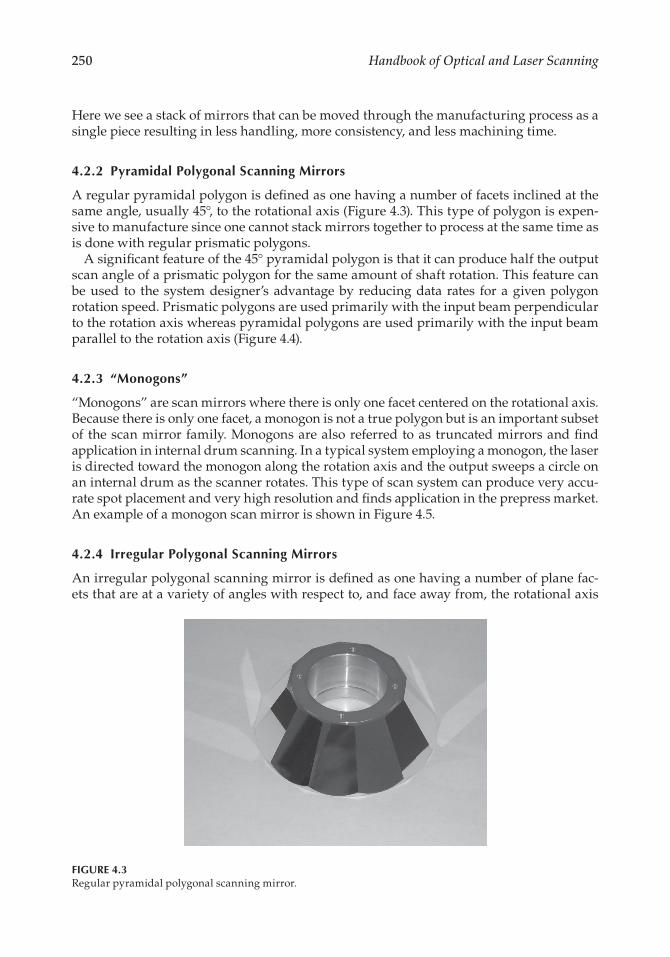
A.regular.pyramidal.polygon.is.defined.as.one.having.a.number.of.facets.inclined.at.the.same.angle,.usually.45°,.to.the.rotational.axis.(Figure.4.3)..This.type.of.polygon.is.expen-sive.to.manufacture.since.one.cannot.stack.mirrors.together.to.process.at.the.same.time.as.is.done.with.regular.prismatic.polygons.
A.significant.feature.of.the.45°.pyramidal.polygon.is.that.it.can.produce.half.the.output.scan.angle.of.a.prismatic.polygon.for.the.same.amount.of.shaft.rotation..This.feature.can.be.used. to. the.system.designer’s.advantage.by. reducing.data. rates. for.a.given.polygon.rotation.speed..Prismatic.polygons.are.used.primarily.with.the.input.beam.perpendicular.to.the.rotation.axis.whereas.pyramidal.polygons.are.used.primarily.with.the.input.beam.parallel.to.the.rotation.axis.(Figure.4.4).
4.2.3 “Monogons”
“Monogons”.are.scan.mirrors.where.there.is.only.one.facet.centered.on.the.rotational.axis..Because.there.is.only.one.facet,.a.monogon.is.not.a.true.polygon.but.is.an.important.subset.of.the.scan.mirror.family..Monogons.are.also.referred.to.as.truncated.mirrors.and.find.application.in.internal.drum.scanning..In.a.typical.system.employing.a.monogon,.the.laser.is.directed.toward.the.monogon.along.the.rotation.axis.and.the.output.sweeps.a.circle.on.an.internal.drum.as.the.scanner.rotates..This.type.of.scan.system.can.produce.very.accu-rate.spot.placement.and.very.high.resolution.and.finds.application.in.the.prepress.market..An.example.of.a.monogon.scan.mirror.is.shown.in.Figure.4.5.
4.2.4 Irregular Polygonal Scanning Mirrors
An.irregular.polygonal.scanning.mirror.is.defined.as.one.having.a.number.of.plane.fac-ets.that.are.at.a.variety.of.angles.with.respect.to,.and.face.away.from,.the.rotational.axis.
FIGURE 4.3Regular.pyramidal.polygonal.scanning.mirror.

PolygonalScanners:Components,Performance,andDesign 251
(Figure.4.6)..The.unique.feature.of.this.type.of.scan.mirror.is.that.it.can.produce.a.raster.output.without.a.second.axis.of.motion..The.resulting.output.scans.are.nonsuperimposing.if.the.facets.are.at.different.angles..This.type.of.scanner.finds.its.way.into.coarse.scanning.applications.such.as:
1. Point-of-sale.barcode.readers2. Laser.heat-treating.systems3. Low.resolution.writing.and.display.systems
Inputbeam
Inputbeam
Regular 45° pyramidal polygon
Regular prismatic polygon
Output
beam
Output
beam
θ
θ2θ
θ
FIGURE 4.4Scan.angle.versus.rotation.angle.
FIGURE 4.5“Monogon.”

252 HandbookofOpticalandLaserScanning
These.polygons.typically.cost.significantly.more.than.regular.polygons.because.their.asymme-try.prevents.cost.savings.from.stacking..Another.disadvantage.of.these.scanners.is.the.inherent.dynamic.imbalance.of.the.polygon.during.rotation..This.limits.use.to.low-speed.applications..A.special.case.where.equal.and.opposing.facets.are.used.on.each.side.of.the.polygon.helps.with.the.balance.problem..The.result.is.the.scan.pattern.is.generated.twice.each.revolution.
Now.that.the.types.of.scan.mirrors.have.been.covered,.a.logical.next.step.is.to.consider.the.materials.used.to.fabricate.the.mirrors..The.following.section.addresses.the.most.com-mon.materials.in.use.today.
4.3 MATERIALS
Material.selection.for.polygonal.mirrors.is.driven.by.considerations.of.performance.and.cost..The.most.common.materials.for.polygonal.mirrors.are.aluminum,.plastic,.and.beryllium..Facet.distortion/flatness.is.a.key.performance.consideration.when.choosing.a.material.
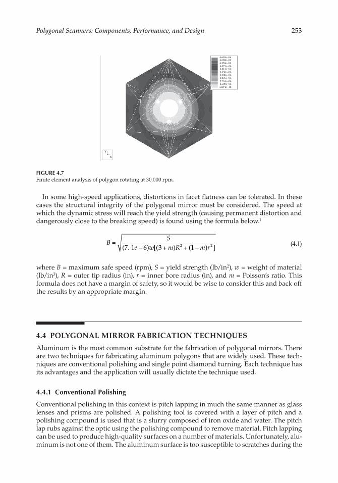
Aluminum.represents.a.good. trade-off.between.cost.and.performance..This.material.has.good.stiffness,.is.relatively.light,.and.lends.itself.to.low-cost.fabrication.methods..The.upper.limit.for.the.use.of.aluminum.mirrors.without.the.risk.of.facet.distortion.beyond.λ/10.is.on.the.order.of.a.tip.velocity.of.76.m/s..Above.this.speed.the.size.of.the.facet,.the.disc. shape,.and. the.mounting.method.all.play.a. role. in. the.distortion.of. the. facet.. It. is.recommended.that.a.finite.element.analysis.be.performed.if.you.intend.to.operate.above.this.level..An.example.of.the.shape.change.due.to.high-speed.rotation,.for.a.six-faceted.polygon,.is.shown.in.Figure.4.7.
Plastic. is.used. in.applications.where.cost. is. the.primary.concern.and.performance. is.good. enough. for. the. application.. An. example. is. in. the. hand-held. barcode. market. and.other. short-range,. low-resolution. scanning. applications.. Injection. molding. techniques.have.come.far.in.the.past.few.years.but.it.is.still.difficult.to.reliably.produce.plastic.mirrors.larger.than.2-mm.diameter.with.facets.flat.to.better.than.1.wave.
Beryllium.has.been.used.successfully.in.applications.where.high.speed.and.low.distor-tion.are.required..It.is.a.very.expensive.substrate.and.produces.toxic.dust.when.machined,.requiring.specialized.extraction.and.filtration.equipment..Therefore.it.does.not.find.wide.usage.and.is.a.very.expensive.solution..Beryllium.is.typically.nickel.plated.prior.to.polish-ing..The.nickel.plating.seals.in.the.beryllium.and.removes.the.risk.of.toxic.dust.
FIGURE 4.6Irregular.polygonal.scanning.mirror.
PolygonalScanners:Components,Performance,andDesign 253
In.some.high-speed.applications,.distortions.in.facet.flatness.can.be.tolerated..In.these.cases. the.structural. integrity.of. the.polygonal.mirror.must.be.considered..The.speed.at.which.the.dynamic.stress.will.reach.the.yield.strength.(causing.permanent.distortion.and.dangerously.close.to.the.breaking.speed).is.found.using.the.formula.below.1
.B
Se w m R m r
=− + + −( . ) [( ) ( ) ]7 6 3 12 2 1 .
(4.1)
where.B = maximum.safe.speed.(rpm),.S = yield.strength.(lb/in2),.w = weight.of.material.(lb/in3),.R = outer.tip.radius.(in),.r = inner.bore.radius.(in),.and.m = Poisson’s.ratio..This.formula.does.not.have.a.margin.of.safety,.so.it.would.be.wise.to.consider.this.and.back.off.the.results.by.an.appropriate.margin.
4.4 POLYGONAL MIRROR FABRICATION TECHNIQUES
Aluminum.is.the.most.common.substrate.for.the.fabrication.of.polygonal.mirrors..There.are.two.techniques.for.fabricating.aluminum.polygons.that.are.widely.used..These.tech-niques.are.conventional.polishing.and.single.point.diamond.turning..Each.technique.has.its.advantages.and.the.application.will.usually.dictate.the.technique.used.
4.4.1 Conventional Polishing
Conventional.polishing.in.this.context.is.pitch.lapping.in.much.the.same.manner.as.glass.lenses.and.prisms.are.polished..A.polishing. tool. is.covered.with.a. layer.of.pitch.and.a.polishing.compound.is.used.that.is.a.slurry.composed.of.iron.oxide.and.water..The.pitch.lap.rubs.against.the.optic.using.the.polishing.compound.to.remove.material..Pitch.lapping.can.be.used.to.produce.high-quality.surfaces.on.a.number.of.materials..Unfortunately,.alu-minum.is.not.one.of.them..The.aluminum.surface.is.too.susceptible.to.scratches.during.the.
4.602e–064.600e–064.338e–064.075e–063.813e–063.550e–063.288e–063.025e–062.763e–062.500e–066.894e–10
xy
FIGURE 4.7Finite.element.analysis.of.polygon.rotating.at.30,000.rpm.
254 HandbookofOpticalandLaserScanning
polishing.process..New.techniques.have.been.developed,.but.these.rely.on.minimal.abra-sive.mixtures.and.therefore.material.removal.rates.that.are.too.slow.to.be.cost.effective.
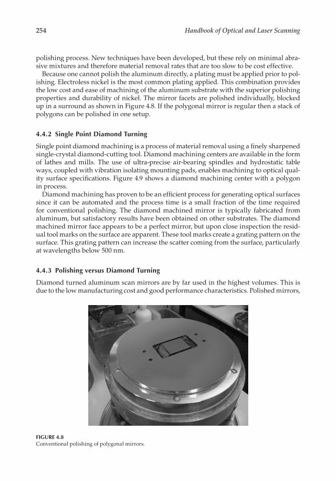
Because.one.cannot.polish.the.aluminum.directly,.a.plating.must.be.applied.prior.to.pol-ishing..Electroless.nickel.is.the.most.common.plating.applied..This.combination.provides.the.low.cost.and.ease.of.machining.of.the.aluminum.substrate.with.the.superior.polishing.properties.and.durability.of.nickel..The.mirror.facets.are.polished.individually,.blocked.up.in.a.surround.as.shown.in.Figure.4.8..If.the.polygonal.mirror.is.regular.then.a.stack.of.polygons.can.be.polished.in.one.setup.
4.4.2 Single Point Diamond Turning
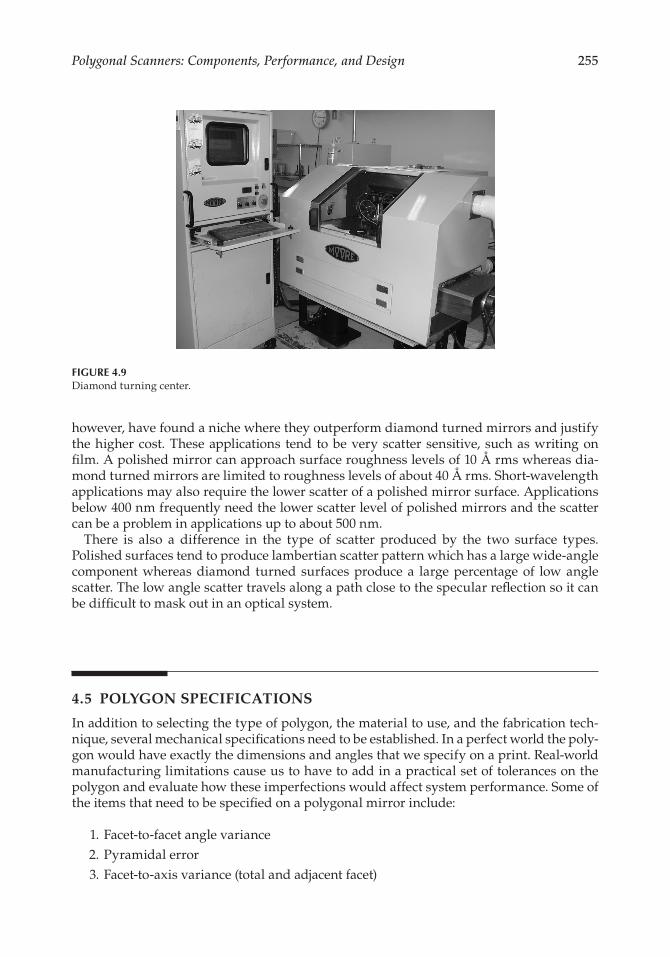
Single.point.diamond.machining.is.a.process.of.material.removal.using.a.finely.sharpened.single-crystal.diamond-cutting.tool..Diamond.machining.centers.are.available.in.the.form.of. lathes. and. mills.. The. use. of. ultra-precise. air-bearing. spindles. and. hydrostatic. table.ways,.coupled.with.vibration.isolating.mounting.pads,.enables.machining.to.optical.qual-ity.surface.specifications..Figure.4.9.shows.a.diamond.machining.center.with.a.polygon.in.process.
Diamond.machining.has.proven.to.be.an.efficient.process.for.generating.optical.surfaces.since. it. can.be.automated.and. the.process. time. is.a.small. fraction.of. the. time.required.for. conventional. polishing.. The. diamond. machined. mirror. is. typically. fabricated. from.aluminum,.but.satisfactory.results.have.been.obtained.on.other.substrates..The.diamond.machined.mirror.face.appears.to.be.a.perfect.mirror,.but.upon.close.inspection.the.resid-ual.tool.marks.on.the.surface.are.apparent..These.tool.marks.create.a.grating.pattern.on.the.surface..This.grating.pattern.can.increase.the.scatter.coming.from.the.surface,.particularly.at.wavelengths.below.500.nm.
4.4.3 Polishing versus Diamond Turning
Diamond.turned.aluminum.scan.mirrors.are.by.far.used.in.the.highest.volumes..This.is.due.to.the.low.manufacturing.cost.and.good.performance.characteristics..Polished.mirrors,.
FIGURE 4.8Conventional.polishing.of.polygonal.mirrors.
PolygonalScanners:Components,Performance,andDesign 255
however,.have.found.a.niche.where.they.outperform.diamond.turned.mirrors.and.justify.the.higher.cost..These.applications. tend. to.be.very.scatter.sensitive,.such.as.writing.on.film..A.polished.mirror.can.approach.surface.roughness.levels.of.10.Å.rms.whereas.dia-mond.turned.mirrors.are.limited.to.roughness.levels.of.about.40.Å.rms..Short-wavelength.applications.may.also.require.the.lower.scatter.of.a.polished.mirror.surface..Applications.below.400.nm.frequently.need.the.lower.scatter.level.of.polished.mirrors.and.the.scatter.can.be.a.problem.in.applications.up.to.about.500.nm.
There. is. also. a. difference. in. the. type. of. scatter. produced. by. the. two. surface. types..Polished.surfaces.tend.to.produce.lambertian.scatter.pattern.which.has.a.large.wide-angle.component. whereas. diamond. turned. surfaces. produce. a. large. percentage. of. low. angle.scatter..The.low.angle.scatter.travels.along.a.path.close.to.the.specular.reflection.so.it.can.be.difficult.to.mask.out.in.an.optical.system.
4.5 POLYGON SPECIFICATIONS
In.addition.to.selecting.the.type.of.polygon,.the.material.to.use,.and.the.fabrication.tech-nique,.several.mechanical.specifications.need.to.be.established..In.a.perfect.world.the.poly-gon.would.have.exactly.the.dimensions.and.angles.that.we.specify.on.a.print..Real-world.manufacturing.limitations.cause.us.to.have.to.add.in.a.practical.set.of.tolerances.on.the.polygon.and.evaluate.how.these.imperfections.would.affect.system.performance..Some.of.the.items.that.need.to.be.specified.on.a.polygonal.mirror.include:
. 1..Facet-to-facet.angle.variance
. 2..Pyramidal.error
. 3..Facet-to-axis.variance.(total.and.adjacent.facet)
FIGURE 4.9Diamond.turning.center.
256 HandbookofOpticalandLaserScanning
. 4..Facet.radius:. i.. nominal.tolerance,. ii.. variation.of.all.facets.tolerance;. 5..Surface.figure.(composed.of.power.and.irregularity). 6..Surface.quality.and.scatter
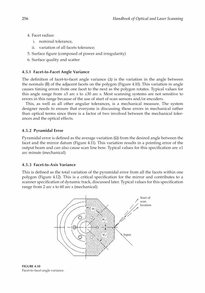
4.5.1 Facet-to-Facet Angle Variance
The. definition. of. facet-to-facet. angle. variance. (Δ). is. the. variation. in. the. angle. between.the.normals.(y).of.the.adjacent.facets.on.the.polygon.(Figure.4.10)..This.variation.in.angle.causes.timing.errors.from.one.facet.to.the.next.as.the.polygon.rotates..Typical.values.for.this.angle.range. from.±5.arc.s. to.±30.arc.s..Most.scanning.systems.are.not.sensitive. to.errors.in.this.range.because.of.the.use.of.start.of.scan.sensors.and/or.encoders.
This,. as. well. as. all. other. angular. tolerances,. is. a. mechanical. measure.. The. system.designer.needs. to.ensure. that. everyone. is.discussing. these.errors. in.mechanical. rather.than.optical.terms.since.there.is.a.factor.of.two.involved.between.the.mechanical.toler-ances.and.the.optical.effects.
4.5.2 Pyramidal Error
Pyramidal.error.is.defined.as.the.average.variation.(Ω).from.the.desired.angle.between.the.facet.and.the.mirror.datum.(Figure.4.11)..This.variation.results.in.a.pointing.error.of.the.output.beam.and.can.also.cause.scan.line.bow..Typical.values.for.this.specification.are.±1.arc.minute.(mechanical).
4.5.3 Facet-to-Axis Variance
This.is.defined.as.the.total.variation.of.the.pyramidal.error.from.all.the.facets.within.one.polygon. (Figure.4.12)..This. is. a. critical. specification. for. the.mirror.and.contributes. to.a.scanner.specification.of.dynamic.track,.discussed.later..Typical.values.for.this.specification.range.from.2.arc.s.to.60.arc.s.(mechanical).
Start ofscan location
Inputψ3
ψ2
ψ1
FIGURE 4.10Facet-to-facet.angle.variance.

PolygonalScanners:Components,Performance,andDesign 257
Another.parameter.related.to.this.is.the.adjacent.facet-to-axis.variance..This.is.defined.as.the.largest.step.in.the.pyramidal.angle.from.one.facet.to.the.next.within.a.polygon..This.is.important.to.control.in.order.to.reduce.banding.artifacts.in.the.final.system..Typical.values.for.this.specification.are.in.the.range.of.1–30.arc.s.(mechanical).
Optical. scanning. systems. may. employ. correction. devices. that. allow. this. value. to. be.reduced..System.resolution.plays.a. large.part. in.determining.the.actual.value.required..Film.writing.applications.tend.to.have.the.tightest.requirements.and.passive.reading.sys-tems.tend.to.have.the.loosest.requirements.
4.5.4 Facet Radius
The.facet.radius.(referred.to.as.facet.height.by.some.manufacturers).is.the.distance.from.the.center.of.the.polygon.to.the.facet..The.variation.in.this.radius.within.the.polygon.and. the. tolerance. on. the. average. radius. are. important. to. specify.. The. average. facet.radius.is.important.because.it. locates.the.facet.in.the.optical.system..The.variation.of.this.radius.within.a.polygon.causes.errors.in.the.focal.plane.location.from.one.facet.to.the.next..It.also.causes.velocity.variations.within.the.scan.line,.which.are.usually.small.and.show.up.as. jitter.errors..Typical.values. for. these.parameters.are.±60.microns.for.the.facet.radius.average.position.and.±25.microns.for.the.facet.radius.variation.within.a.polygon.
Desired facet pointingActual facet pointing
Desired output2Ω
ΩΩ
Actual output
FIGURE 4.11Pyramidal.error.
Variation in facetpointing for all facets
Inputoutputs
Reflect
ed
outputs
FIGURE 4.12Facet-to-axis.variance.
258 HandbookofOpticalandLaserScanning
4.5.5 Surface Figure
Surface.figure.is.the.macro.shape.of.the.polygon.facet.and.is.measured.as.the.deviation.from.an.ideal.flat.surface..The.flatness.of.polygon.facets.will.have.an.impact.both.on.the.aberrations.in.the.beam.as.well.as.the.pointing.of.the.beam..The.aberrations.can.affect.the.final.focused.spot.size.in.the.scan.system..The.pointing.error.results.in.velocity.variations.across.the.scan.
Several.factors.influence.the.flatness.of.polygon.facets:
. 1.. Initial.fabrication.tolerances
. 2..Distortion.due.to.mounting.stresses
. 3..Distortion.due.to.forces.induced.when.rotating.at.high.speeds
. 4..Distortion.due.to.long-term.stress.relief
Interferometers.are.commonly.used.to.measure.static.flatness..The.flatness.is.specified.in.wavelengths,.λ,.(or.fractions.thereof).of.light..A.typical.flatness.specification.is:.λ/8.at.633 nm..Departure.from.flatness.can.have.a.variety.of.forms,.depending.on.how.the.sur-face.was.fabricated..For.example,.conventionally.polished.mirror.surfaces.tend.to.depart.from.flat.in.a.regular.spherical.form,.either.convex.or.concave..Diamond.machined.surfaces.usually.depart.from.flat.in.a.regular.cylindrical.form,.either.convex.or.concave..A.polygon.will.typically.have.two.specifications.related.to.flatness,.a.surface.power.specification.and.irregularity..The. irregularity. is.defined.as. the.deviation.from.a.best-fit.sphere..Another.common.way.of.specifying.the.optical.surface.is.in.terms.of.power.and.pv—power.(peak.to.valley.error.minus.power),.which.separate.the.regular.and.irregular.shapes..Most.poly-gons.used.in.printing.applications.are.specified.in.the.λ/8.to.λ/10.range.at.the.wavelength.of.interest.
4.5.6 Surface Quality and Scatter
Ideally.a.reflective.optical.surface.will.reflect.all.of.the.incident.light.without.introducing.any. scattered. components.. In. reality. an. optical. surface. has. multiple. defects. of. various.sizes..The.U.S..military.developed.a.scratch.and.dig.specification.for.surface.defects,.which.is.included.in.MIL-PRF-13830B.and.is.in.broad.use.within.the.optics.industry..This.method.of.quality.determination.involves.close.examination.of.a.surface.and.identifying.a.scratch.and.dig.level.in.a.given.unit.area..A.typical.high-quality.conventionally.polished.polygon.will.have.a.quality.level.of.40–20.scratch.and.dig.
Machined.optical.surfaces.on.the.other.hand,.are.made.up.of.a.precise.regular.pattern.of.machine.tool.marks,.which.are.sufficiently.high.in.frequency.and.low.in.height.errors.as.to.behave.as.a.plane.mirror.at.most.visible.and.infrared.wavelengths..The.scratch.and.dig. specification. must. be. supplemented. with. an. additional. measure. of. surface. quality.here..A more.representative.definition. for. the.overall.surface.quality. is. the.rms.surface.roughness..The.rms.surface.roughness.can.be.measured.directly.by.mechanical.or.optical.profilometry.means.or.indirectly.by.measuring.the.scatter.from.the.surface.
A.special.test.system.is.required.to.measure.the.scatter.from.the.surface.and.correlate.this.to.an.rms.roughness.value..Different.tests.must.be.used.for.the.measurement.of.scat-ter. of. diamond. turned. and. conventionally. polished. mirrors.. Diamond. turned. surfaces.produce.a.significant.fraction.of.scattered.energy.in.a.narrow.cone.around.the.reflected.beam..Conventionally.polished.mirrors.have.the.majority.of. their.scattered.energy.in.a.cone.significantly.greater.than.the.divergence.angle.of.the.reflected.beam.

PolygonalScanners:Components,Performance,andDesign 259
Conventionally.polished.mirrors.can.be.tested.using.an.integrating.sphere.that.gathers.a.wide.cone.angle.(Figure.4.13)..Scattered.light.in.the.cone.of.4–180°.is.gathered.with.this.test.method..The.diamond.turned.mirrors.can.be.tested.using.a.combination.of.the.integrating.sphere.and.a.near.angle.test.(Figure.4.14)..Scattered.light.in.the.cone.of.0.4–4°.is.gathered.using.this.test.
A.correlation.has.been.developed.between.the.rms.surface.roughness.and.the.total.inte-grated.scattered.incident.light:2
.rms roughness =
−( )lp
ln TIS1
4 .(4.2)
where.TIS is.the.total.integrated.scatter.
Exit port
Polygon under test
Specularreflection
Integrating sphere
Entranceport
Incidentlaser
Detector
FIGURE 4.13Test.for.wide.angle.scatter.
Spatialfilter
Laser
Polygon under test
Focussing/recollimatinglenses
30''
Ø1.875
Ø.281 centralobstruction
Lens Detector
FIGURE 4.14Test.for.near.angle.scatter.

260 HandbookofOpticalandLaserScanning
The.combination.of.scratch.and.dig.along.with.rms.surface.roughness.provide.a.good.description.of.the.surface.structure.higher.in.frequency.than.surface.figure.
4.6 THIN FILM COATINGS
There.are.two.major.functions.of.optical.coatings.on.polygons:.to.improve.the.reflectance.of.the.surface.and/or.to.improve.durability..In.the.case.of.diamond.machined.polygons,.the.substrate.is.usually.aluminum.(in.itself.a.good.reflector.over.most.of.the.visible.spec-trum)..This.aluminum.surface.is.too.soft.without.a.coating..It.is.easily.scratched.during.even.a.light.cleaning.so.one.solution.is.to.apply.a.thin.layer.of.silicon.monoxide,.a.dielectric.material,.as.a.surface.protector..The.optical.thickness.is.usually.about.one-half wavelength.at.the.wavelength.of.interest..This.material.is.more.durable.than.the.base.aluminum.and.can.be.readily.cleaned..The.coating.just.described.is.typically.referred.to.as.a.protected.aluminum.coating..This.coating.has.a.reflectivity.of.>88%.across.the.450–650.nm.range.
The.protected.aluminum.coating.is.fine.for.many.applications.and.because.of.its.simplic-ity.is.relatively.inexpensive..Many.applications,.however,.require.enhancement.coatings.due.to.needs.for.higher.reflectivity.performance.at.various.wavelengths.
The.first.layer.deposited.in.most.applications.is.a.binding.layer,.then.a.metal,.such.as.aluminum,.silver,.or.gold..The.layer.or.layers.above.the.metal.are.composed.of.dielectric.materials..The.metal.is.selected.based.on.the.wavelengths.of.interest..As.mentioned.earlier,.aluminum.is.a.good.choice.in.the.visible.region..It.is.also.selected.for.ultraviolet.applica-tions.since.its.reflectivity.can.be.enhanced.in.this.region.with.a.dielectric.stack..Gold.is.often.selected.as.the.base.metal.in.applications.above.600.nm..It.has.good.reflectivity.at.600 nm.(90%).and.very.good.reflectivity.from.1.micron,.out.past.10.6.microns.(>98%).
Silver.exhibits.very.desirable.reflectance.characteristics.over.a.broad.spectrum.and.is.fre-quently.considered.as.a.material.for.polygon.coating..In.practice,.however,.it.is.frequently.a.disappointing.choice. for. the. long. term..The.slightest.pinhole. (or.minute.scratch. from.cleaning).will.expose.the.silver.to.reactive.contaminants.from.the.atmosphere,.which.over.time.(several.days.or.weeks).will.diffuse.into.the.silver,.producing.an.expanding.blemish..Aluminum,.which.initially.exhibits.somewhat.lower.values.of.reflectance.than.silver,.is.far.superior.in.terms.of.durability.
Common.dielectric.materials.used.to.protect.the.surface.and.enhance.reflectivity.are.sil-icon.monoxide,.silicon.dioxide,.hafnium.oxide,.and.titanium.dioxide..A.quarter.wave.stack.combining.high. refractive. index.and. low.refractive. index.materials. is.used. to.enhance.the.reflectivity.in.the.wavelength.region.of. interest..The.term.quarter.wave.stack.refers.to.an.alternating.series.of.high.and.low.index.materials.that.are.one-quarter.of.an.opti-cal.wavelength.thick.at.the.wavelength.of.interest..The.design.of.this.quarter.wave.stack.can.be.tailored.to.raise.the.reflectivity.of.the.base.metal.significantly.in.various.regions.of.interest..Most.companies.will.offer.a.variety.of.standard.reflectivity.enhancing.coatings.for.different.wavelengths.
Thin.film.coatings.are.applied.in.vacuum.deposition.chambers.such.as.the.one.shown.in.Figure.4.15..The.tooling.to.coat.a.polygon.is.specialized.because.the.polygon.has.opti-cal.surfaces.around.its.periphery..The.polygons.are.stacked.onto.coating.arbors.that.are.placed.in.the.chamber.above.the.evaporant.sources..The.arbors.are.rotated.with.a.drive.mechanism.during.the.deposition.process.at.a.constant.rate.so.that.all.facets.will.see.the.same.thickness.of.coating.material..The.rotation.rate.must.be.fast.enough.that.the.time.for.

PolygonalScanners:Components,Performance,andDesign 261
one.revolution.is.a.small.fraction.of.the.deposition.time.for.a.single.layer..Otherwise.there.will.be.significant.variation.around.the.polygon.depending.on.when.the.shutter.is.opened.and.closed.
Reflectance. uniformity. both. within. a. facet. and. facet-to-facet. is. an. important. poly-gon.specification..The.reflectance.uniformity.can.impact.the.accuracy.of.written.or.read.images.. In.practice,. the.reflectance.uniformity.of.rather. large.polygon.facets. (e.g.,.a. few.inches.square).is.more.difficult.to.achieve.than.if.the.facets.are.small.(e.g.,.1
2in.square)..This.has.to.do.with.the.consistency.of.the.cleaning.of.the.surface.prior.to.coating.and.the.varia-tions.in.deposition.rates.with.location.and.time.within.the.coating.chamber.
Aluminum.polygons.cannot.be.heated.up.to.high.temperatures.during.a.coating.run.as.one.would.typically.do.for.good.adhesion.and.layer.density..The.shape.of.the.polygons.makes.them.susceptible.to.slight.stress.changes.during.this.heating.cycle..This.results.in.changes.to.the.facet.flatness..The.coating.process.should.be.designed.to.keep.the.polygons.below.a.temperature.of.225°C.to.maintain.the.flatness.
Crucial.to.all.of.the.desired.characteristics.of.the.coating.of.a.polygon.is.its.cleanliness.prior.to.coating..Irrespective.of.the.fabrication.methods,.polygons.will.be.handled.prior.to.coating.during.the.inspection.processes,.transport,.and.installation.into.the.coating.cham-ber..The.polygon.must.be.cleaned.thoroughly.to.remove.foreign.material.that.will.degrade.surface.quality,.prevent.good.coating.adhesion,.or.outgas.in.the.coating.system.
Several.tools.are.available.to.measure.the.optical.performance.of.the.coating..Common.measuring.tools.to.determine.reflectance.are.spectrophotometers.and.laser.reflectometers..Spectrophotometers.are.used.to.provide.information.on.the.reflectance.versus.wavelength..The.majority.of.spectrophotometers.with.a.reflectance.measuring.attachment.are.limited.to.small. sample.sizes.on. the.order.of.1. to.2. in. in.diameter..This. fact.usually.precludes.measuring.the.polygon.itself..A.witness.sample.is.coated.at.the.same.time.as.the.polygon.and.can.be.used.to.represent.the.actual.part.performance..This.can.be.a.reliable.method.of.ascertaining.the.performance.of.the.polygon.as.long.as.the.witness.sample.has.a.similar.surface.preparation.and.quality. level. to. the.polygon..This.means. that.diamond. turned.witness. samples. should. be. used. with. diamond. turned. polygons. and. polished. witness.samples.used.with.polished.mirrors.
FIGURE 4.15Thin.film.deposition.chamber.
262 HandbookofOpticalandLaserScanning
Laser.reflectometers.compare.the.reflected.beam.to.the.incident.beam.at.a.specific.wave-length.and.can.be.designed.to.test.over.a.range.of.angles.with.either.S.or.P.polarization..Reflectometers. are. useful. for. determining. performance. at. one. specific. wavelength. but.cannot.provide.broadband.information.
4.7 MOTORS AND BEARING SYSTEMS
The.polygonal.mirror.requires.a.bearing.system.and.a.drive.mechanism.to. turn. it. into.a.functional.scanner..Drive.mechanisms.include.pneumatic,.AC.hysteresis.synchronous,.and.brushless.DC..Bearing.systems.used.in.most.applications.are.ball.bearing,.aerostatic.air.bearings,.or.aerodynamic.air.bearings.
4.7.1 Pneumatic Drives
Much.of.today’s.scan.mirror.technology.has.evolved.from.the.development.of.ultra-high-speed.polygon/turbine.motors.for.the.high-speed.photography.industry..Compressed.air.turbines.continue.to.offer.an.attractive.method.of.rotating.a.polygonal.mirror.at.speeds.beyond.the.capability.of.electric.motors..The.advantages.of.turbine.drives.are:
. 1..Substantial.horsepower.can.be.delivered.to.the.scan.mirror.to.produce.rapid.accel-eration.and.very.high.speed.(up.to.1,000,000.rpm).
. 2..Compact.in.size.and.low.in.weight.in.proportion.to.delivered.power.
. 3..Can.be.equipped.with.shaft.seals.so.that.the.scan.mirror.can.be.used.in.a.partial.vacuum.
The.disadvantages.of.turbine.drives.are:
. 1..Require.a.compressed.air.source
. 2..Asynchronous.devices
. 3..Relatively.high.in.cost
. 4..Relatively.short.total.running.life
Pneumatic. drives. are. only. recommended. for. short. duty. cycles. and. where. ultra-high.speed.is.essential.
4.7.2 Hysteresis Synchronous Motors
The.rotor.of.a.hysteresis.synchronous.motor.is.usually.fabricated.from.a.single.piece.of.hardened.steel.selected.out.of.a.group.(predominantly.alloyed.with.cobalt).that.exhibits.substantial.hysteresis.loss..This.resistance.to.the.movement.of.magnetic.flux.in.the.mate-rial.imparts.torque.to.a.rotor.out.of.sync.with.the.drive.current..This.torque.is.responsible.for.the.motor’s.ability.to.start.rotation..When.the.rotor.approaches.the.speed.of.the.stator.flux,.it.becomes.permanently.magnetized.and.“locks.in”.to.synchronism.with.the.drive..If.the.motor.is.turned.off.and.restarted,.the.stator.flux.demagnetizes.the.rotor.and.hysteresis.

PolygonalScanners:Components,Performance,andDesign 263
takes.over.again..The.synchronous.mode.of.operation.is.more.efficient.than.the.hysteresis.or.startup.mode,.and.in.many.systems.a.sync.detector.is.used.to.reduce.drive.current.after.the.motor.is.locked.in.to.save.energy.and.reduce.heating.
AC.hysteresis.synchronous.motors.exhibit.a.characteristic.called.phase.jitter.(hunting)..The.rotors.behave.as.though.they.were.coupled.to.the.drive.waveform.by.a.spring..Within.synchronism. the. rotor. springs. forward. and. back. in. phase. at. a. rate. determined. by. the.spring.rate.(flux.density).and.the.torque/inertia.ratio.of.the.system..Typically,.the.frequency.of.this.phase.jitter.is.in.the.range.of.0.5–3.Hz,.at.an.amplitude.of.a.few.degrees.(1–6°.peak.to.peak)..Under.perfect.conditions.this.jitter.damps.to.zero.values.of.amplitude..However,.perfection.is.seldom.seen.and.continual.recurrence.of.jitter.may.be.expected,.caused.by.electrical. transients.on. the. input,.mechanical. shock. to. the.assembly,.variable. resistance.torque.of.the.motor.bearings,.and.so.on..For.many.systems.the.0.5–0.01%.velocity.error.contribution.of.phase.jitter.is.acceptably.small..If.this.is.not.the.case.then.a.feedback.loop.is.needed.to.reduce.this.level.
4.7.3 Brushless DC Motors
Brushless.DC.motors.are.by.far.the.most.common.motor.used.to.drive.polygonal.scanners..These.motors.use.a.permanent.motor.magnet.and.a.stator.that.supplies.the.varying.mag-netic.force..Motor.magnets.are.composed.of.various.materials.including.neodymium.and.ferrite.depending.on.the.application..Stators.can.be.iron-based.or.ironless,.with.or.without.teeth..The.number.of.magnetic.poles.is.usually.determined.by.the.operating.speed..Low-speed.motors.tend.to.have.higher.pole.counts.(8–12).while.higher.speed.motors.(>10,000.rpm).tend.to.have.lower.pole.counts.(4–6)..The.reason.for.the.large.number.of.poles.at.low.speed.is.to.achieve.smoother.rotation..At.higher.speeds.this.is.not.required.and.the.lower.pole.count.motors.have.less.losses.because.the.stator.flux.speed.is.lower.
Brushless.motors.do.not.have.the.hunting.problem.associated.with.AC.hysteresis.syn-chronous.motors..The.motor.controls.used.to.drive.these.motors.can.hold.a.tighter.control.loop..These.motors.can.exhibit.more.high-frequency.variations.due.to.the.torque.available.to.rapidly.change.speed..This.high-frequency.velocity.change.is.referred.to.as.jitter..The.amount.of.jitter.is.related.to.the.rotor.inertia.and.the.number.of.feedback.pulses.per.revolu-tion..At.higher.speeds.the.inertia.smoothes.out.the.rotation.and.limits.the.amount.of.jitter..At.lower.speeds.the.number.of.feedback.pulses.helps.keep.the.control.loop.errors.small.and.therefore.less.velocity.jitter.when.the.motor.has.a.correction.torque.applied..Hall.effect.devices.are.used.at.higher.speeds.to.provide.magnetic.position.feedback.to.the.controller..Hall.effect.devices.at.lower.speeds,.where.inertia.is.lower,.can.induce.jitter.as.the.controller.chases.the.positional.and.triggering.errors.of.the.Hall.effect.devices..At.lower.speeds.an.encoder.on.the.rotor.may.be.required.to.achieve.low.jitter.levels..Even.incremental.encod-ers.can.induce.jitter.errors.due.to.disc.quality,.alignment,.and.component.quality.
4.7.4 Bearing Types
Polygonal.scanners.require.a.bearing.support.system.to.allow.the.rotor.to.rotate..The.most.common.bearings.used.in.scanners.are:
. 1..Ball.bearings
. 2..Aerostatic.air.bearings
. 3..Aerodynamic.air.bearings

264 HandbookofOpticalandLaserScanning
These.three.types.of.bearing.systems.are.discussed.in.detail.in.other.chapters.in.this.book..Ball.bearings.are.used.where.possible.due.to.their.low.cost..Applications.requiring.speeds.less.than.20,000.rpm.and.that.can.tolerate.bearing.nonrepeatable.errors,.both.in.scan.and.cross.scan,.are.candidates.for.ball.bearings.
Aerodynamic.air.bearings.have.made.large.inroads.in.laser.scanning.since.the.1980s..An.aerodynamic.bearing.generates.its.own.air.pressure.as.it.rotates..It.is.commonly.designed.with.two.close-fitting.cylinders.for.the.radial.bearing..The.axial.bearing.can.be.either.an.air.thrust.bearing.or.magnetic.bearing..These.systems.have.many.advantages.over.both.conventional.ball.bearing.systems.and.aerostatic.air.bearings..The.speed.range.for.aero-dynamic.bearings.is.from.approx..4000.rpm.to.over.100,000.rpm..These.bearings.are.only.slightly.more.costly.than.an.equivalent.ball.bearing.system..There.is.no.wear.while.operat-ing.and.they.require.no.external.pressure.support.equipment..These.bearings.have.been.developed.to.withstand.over.20,000.start/stop.cycles..Aerodynamic.bearings.do.have.some.limitations. that. limit. their.application..They.are.not.well. suited. to.dirty.environments..Many. designs. exchange. outside. air. frequently. during. operation,. thereby. ingesting. the.outside.debris..Most.designs.cannot.withstand.high.shock.loads.because.the.bearing.stiff-ness.is.limited..The.mass.of.the.optic.is.limited.in.many.applications.due.to.both.the.lack.of.support.and.the.need.to.withstand.constant.starting.and.stopping..Additional.mass.causes.added.wear.to.the.bearing.during.startup.and.shutdown.
Aerostatic.air.bearings.provide.the.ultimate.in.performance.at.a.high.cost..An.aerostatic.bearing.uses.pressurized.air.and.closely.spaced.axial.and.radial.bearing.surfaces.to.float.the.rotor..When.pressurized,.the.bearing.has.no.contacting.parts,.resulting.in.extremely.long.life..These.bearings.are.very.stiff.and.have.wobble.errors.less.than.1.arc.s..They.are.capable.of.supporting.heavy.loads.and.do.not.suffer.from.wear.at.startup.and.shutdown..They.do.require.external.components.to.supply.the.pressure.to.the.bearing..This.increases.system.complexity.as.well.as.cost.
4.8 SCANNER SPECIFICATIONS
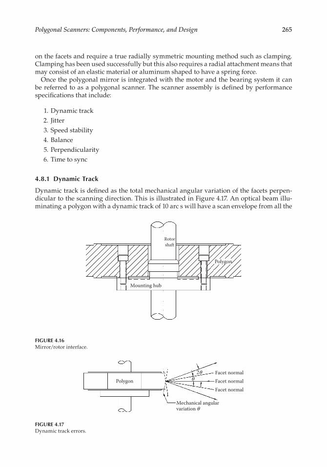
Once.the.polygon,.motor,.and.bearing.system.have.been.decided.on,.the.packaging.of.the.assembly.becomes.the.next.concern..One.of. the.key.elements. in.attaining.high.scanner.performance.is.the.mounting.of.the.scan.mirror.to.the.rotating.spindle.
To.preserve.the.facet.flatness.achieved.during.initial.polygon.fabrication,.it.is.necessary.to.fasten.the.polygon.to.its.drive.spindle.with.care,.particularly.if.λ/8.or.better.flatness.is.required..The.interface.between.the.mirror.and.the.rotor.must.not.induce.stress.in.the.mir-ror.that.is.translated.out.to.the.facets.
A.typical.mounting.scheme.is.shown.in.Figure.4.16..In.this.case.the.datum.surface.of.the.polygon.and.the.locating.annulus.of.the.mounting.hub.are.lapped.to.optical.quality.so.that.when.the.two.are.firmly.held.together,.distortions.are.minimized.
Equally.important.to.the.accurate.mounting.of.mirror.datum.and.rotor.hub.surfaces.is.cleanliness.at.assembly.and.the.appropriate.torque.levels.of.the.fastening.screws..Polygons.can.be.attached.in.the.manner.described.in.low-.and.medium-speed.applications..When.tip.velocities.approach.76.m/s,.other.methods.of.mounting.need.to.be.considered.
In.many.applications.the.facets.can.be.allowed.to.distort.as.long.as.they.all.change.by.the.same.amount..A.symmetrical.mounting.method.with.screws.aligned.with.every.apex.will.work.in.this.type.of.application..Other.applications.cannot.stand.significant.shape.change.
PolygonalScanners:Components,Performance,andDesign 265
on.the.facets.and.require.a.true.radially.symmetric.mounting.method.such.as.clamping..Clamping.has.been.used.successfully.but.this.also.requires.a.radial.attachment.means.that.may.consist.of.an.elastic.material.or.aluminum.shaped.to.have.a.spring.force.
Once.the.polygonal.mirror.is.integrated.with.the.motor.and.the.bearing.system.it.can.be.referred.to.as.a.polygonal.scanner..The.scanner.assembly.is.defined.by.performance.specifications.that.include:
. 1..Dynamic.track
. 2.. Jitter
. 3..Speed.stability
. 4..Balance
. 5..Perpendicularity
. 6..Time.to.sync
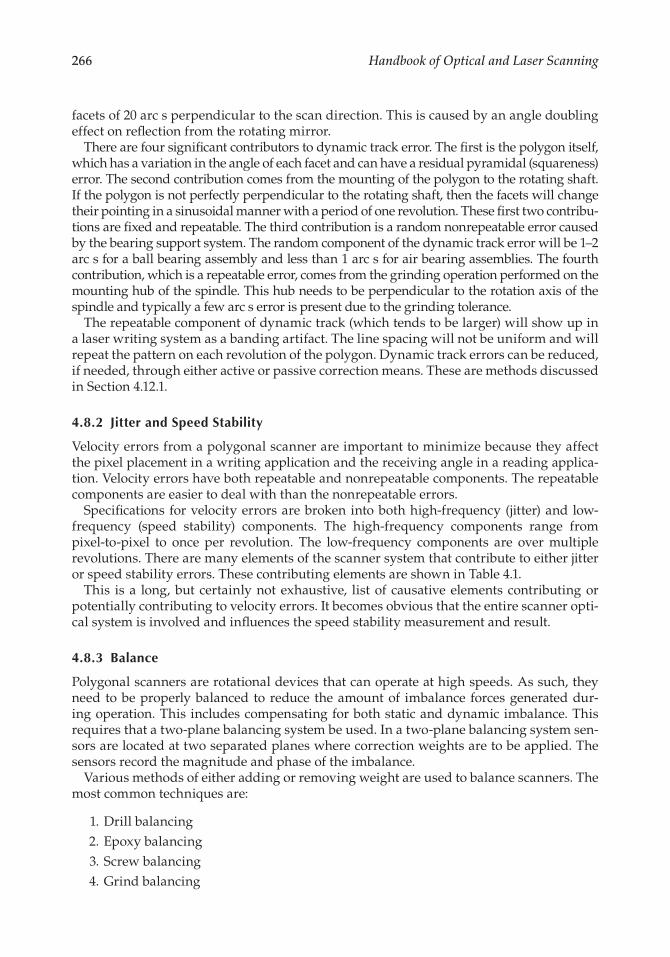
4.8.1 Dynamic Track
Dynamic.track.is.defined.as.the.total.mechanical.angular.variation.of.the.facets.perpen-dicular.to.the.scanning.direction..This.is.illustrated.in.Figure.4.17..An.optical.beam.illu-minating.a.polygon.with.a.dynamic.track.of.10.arc.s.will.have.a.scan.envelope.from.all.the.
Rotorshaft
Polygon
Mounting hub
FIGURE 4.16Mirror/rotor.interface.
Polygon
Mechanical angularvariation θ
θ2θ Facet normal
Facet normalFacet normal
FIGURE 4.17Dynamic.track.errors.
266 HandbookofOpticalandLaserScanning
facets.of.20.arc.s.perpendicular.to.the.scan.direction..This.is.caused.by.an.angle.doubling.effect.on.reflection.from.the.rotating.mirror.
There.are.four.significant.contributors.to.dynamic.track.error..The.first.is.the.polygon.itself,.which.has.a.variation.in.the.angle.of.each.facet.and.can.have.a.residual.pyramidal.(squareness).error..The.second.contribution.comes.from.the.mounting.of.the.polygon.to.the.rotating.shaft..If.the.polygon.is.not.perfectly.perpendicular.to.the.rotating.shaft,.then.the.facets.will.change.their.pointing.in.a.sinusoidal.manner.with.a.period.of.one.revolution..These.first.two.contribu-tions.are.fixed.and.repeatable..The.third.contribution.is.a.random.nonrepeatable.error.caused.by.the.bearing.support.system..The.random.component.of.the.dynamic.track.error.will.be.1–2.arc.s.for.a.ball.bearing.assembly.and.less.than.1.arc.s.for.air.bearing.assemblies..The.fourth.contribution,.which.is.a.repeatable.error,.comes.from.the.grinding.operation.performed.on.the.mounting.hub.of.the.spindle..This.hub.needs.to.be.perpendicular.to.the.rotation.axis.of.the.spindle.and.typically.a.few.arc.s.error.is.present.due.to.the.grinding.tolerance.
The.repeatable.component.of.dynamic.track.(which.tends.to.be.larger).will.show.up.in.a.laser.writing.system.as.a.banding.artifact..The.line.spacing.will.not.be.uniform.and.will.repeat.the.pattern.on.each.revolution.of.the.polygon..Dynamic.track.errors.can.be.reduced,.if.needed,.through.either.active.or.passive.correction.means..These.are.methods.discussed.in.Section.4.12.1.
4.8.2 Jitter and Speed Stability
Velocity.errors.from.a.polygonal.scanner.are.important.to.minimize.because.they.affect.the.pixel.placement.in.a.writing.application.and.the.receiving.angle.in.a.reading.applica-tion..Velocity.errors.have.both.repeatable.and.nonrepeatable.components..The.repeatable.components.are.easier.to.deal.with.than.the.nonrepeatable.errors.
Specifications.for.velocity.errors.are.broken.into.both.high-frequency.(jitter).and.low-frequency. (speed. stability). components.. The. high-frequency. components. range. from.pixel-to-pixel. to. once. per. revolution.. The. low-frequency. components. are. over. multiple.revolutions..There.are.many.elements.of.the.scanner.system.that.contribute.to.either.jitter.or.speed.stability.errors..These.contributing.elements.are.shown.in.Table.4.1.
This. is.a. long,.but.certainly.not.exhaustive,. list.of. causative.elements.contributing.or.potentially.contributing.to.velocity.errors..It.becomes.obvious.that.the.entire.scanner.opti-cal.system.is.involved.and.influences.the.speed.stability.measurement.and.result.
4.8.3 Balance
Polygonal.scanners.are.rotational.devices.that.can.operate.at.high.speeds..As.such,.they.need. to.be.properly.balanced. to.reduce. the.amount.of. imbalance. forces.generated.dur-ing.operation..This.includes.compensating.for.both.static.and.dynamic.imbalance..This.requires.that.a.two-plane.balancing.system.be.used..In.a.two-plane.balancing.system.sen-sors.are.located.at.two.separated.planes.where.correction.weights.are.to.be.applied..The.sensors.record.the.magnitude.and.phase.of.the.imbalance.
Various.methods.of.either.adding.or.removing.weight.are.used.to.balance.scanners..The.most.common.techniques.are:
. 1..Drill.balancing
. 2..Epoxy.balancing
. 3..Screw.balancing
. 4..Grind.balancing

PolygonalScanners:Components,Performance,andDesign 267
The.preferred.approach.for.high-speed.operation.is.either.grinding.or.drilling.to.remove.material..The.addition.of.material.always.brings.risk.of.improper.attachment.and.slinging.of.bonding.agents.
Unbalance.is.typically.measured.in.mg.mm,.a.mass.multiplied.by.the.distance.from.the.rotational.axis..An.unbalance.of.100.mg.mm,.for.example,.indicates.one.side.of.the.rotor.has.excess. mass.equivalent. to.100.mg.at. a.1-mm.radius..Typical.values. for. small. high-speed.scanners.range.from.10.to.100.mg.mm..The. impact.of.unbalance.on.a.scanner. is.vibration..This.vibration.can.be.measured.and.from.this.the.actual.scanner.unbalance.can.be.calculated.
4.8.4 Perpendicularity
Another. important. scanner. parameter. is. the. perpendicularity. of. the. rotation. axis. to.the. mounting. datum.. This. is. important. to. ensure. proper. pointing. of. the. beam. after.reflection.from.the.polygon.and.to.minimize.the.bow.that.can.be.created.by.striking.the.polygon.out.of.the.rotation.plane..A.typical.specification.for.perpendicularity.is.3.to.5 arc.minutes.
TABLE 4.1
Elements.Contributing.to.Jitter.or.Speed.Stability.Errors
Primary causes•. Optical.system
Fixed.geometric.errors.of.the.scan.lens•. Electronic.driver.stability
Frequency.and.phase.stabilityVoltage.stabilityNoise•. Motor.characteristics
AC.motor.hunting.(low.frequency)Cogging.(high.frequency)•. Bearing.behavior
Varying.resistance.torque.from.lube.migrationRoughness.from.wear.and/or.dirtBearing.preload•. Polygonal.mirror.characteristics
FlatnessFacet.radius.variation.(distance.from.center.of.rotation)•. Environmental.(external.shocks.and.vibrations)•. Encoder.errors—sine.wave.errors.due.to.disk.centering
Secondary causes
•. Reflectance.uniformity•. SOS.detector/amplifier.noise•. Facet.(polygon).surface.roughness•. Air.turbulence.in.the.optical.path.(high-speed.systems)•. Polygon/motor.tracking.accuracy•. Laser.pointing.errors.(dynamic)

268 HandbookofOpticalandLaserScanning
4.8.5 Time to Synchronization
The.time.that.it.takes.for.the.scanner.to.reach.operating.speed.from.a.stopped.condition.can.be.important.in.some.applications..This.is.a.function.of.the.motor/winding.and.the.available.current.as.well.as.the.rotor.inertia.and.the.windage.that.must.be.overcome.as.the.scanner.approaches.operating.speed..Typical.values.range.from.3.to.60.s.
4.9 SCANNER COST DRIVERS
Polygonal.scanners.can.range.from.low-cost,.easy-to-manufacture.units,.to.high-cost.state-of-the-art.devices.. It. is. important.when.designing.a.scan.system.to.understand.the.cost.drivers..One.should.try.to.minimize.the.overall.cost.through.system.level.trade-offs..The.scanner.assembly.has.many.cost.drivers.including:
. 1..Polygon.shape
. 2..Number.of.facets
. 3..Fabrication.method,.conventionally.polished.or.diamond.turned
. 4..Optical.specifications.including.surface.figure,.surface.roughness,.and.scratch/dig
. 5..Coating.requirements
. 6..Polygon.size
. 7..Type.of.bearing.system
. 8..Speed
. 9..Velocity.stability
. 10..Dynamic.track.specification
In.an.earlier.section.the.various.shapes.of.polygons.were.discussed.. In.order. to.reduce.costs.it.is.advisable.when.possible.to.select.either.a.regular.polygon.or.a.monogon..The.other.polygon.shapes.have.cost.penalties.that.may.or.may.not.be. justified.based.on.the.application..While.polygons.can.be.manufactured.with.any.number.of.facets,.fewer.facets.result.in.lower.cost..This.is.not.a.large.cost.component.in.a.diamond.turned.mirror.but.has.a.large.impact.on.the.cost.of.a.polished.mirror.
The.selection.of.diamond.turned.or.polished.mirror.has.a.major.impact.on.scanner.cost..Diamond.turned.mirrors.are.the.lowest.cost.and.have.surface.roughness.values.greater.than.40.Å.rms..Conventionally.polished.mirrors.are.more.costly.but.can.bring.the.surface.roughness.down.to.10.Å.rms..All.but.the.most.scatter-sensitive.short-wavelength.systems.can.use.diamond.turned.mirrors.
The.optical.specification.of.surface.figure.can.also.have.a.large.influence.on.cost..Optical.surface.figure.values.of.λ/4.per.inch.at.633.nm.are.common.but.surface.figure.values.down.to.λ/20.can.be.achieved.at.additional.cost..A.scratch/dig.specification.of.80/50.is.a.typical.standard,.but.specifications.down.to.10/5.can.be.achieved.at.significantly.higher.cost.
The.optical.coating.chosen.for. the.polygon.can.have.a.minor. impact.on.the.cost..The.lowest. cost. option. is. a. simple. aluminum. coating. with. a. silicon. monoxide. overcoat.. As.the. reflectivity. specifications. get. higher,. more. dielectric. layers. are. needed. to. enhance.the. reflectivity,. which. can. increase. chamber. time. and. therefore. costs.. Gold. is. another.
PolygonalScanners:Components,Performance,andDesign 269
expensive.coating.option.for.the.infrared..The.inherent.high.reflectivity.of.gold.across.the.IR.spectrum.is.often.worth.the.cost.of.the.material.
Bearing.selection.can.have.a.significant.effect.on.cost..In.the.speed.range.of.500–4000.rpm,.the.choice.is.between.ball.bearings.and.aerostatic.air.bearings..Ball.bearing.scanners.are.relatively.low.in.cost.and.are.the.appropriate.solution.for.many.applications,.but.are.susceptible.to.damage,.generate.many.vibration.frequencies,.and.can.create.motor.speed.instability.. Aerostatic. scanners. are. costly. and. require. support. equipment,. but. offer. the.ultimate.in.scanning.performance.
The.bearing.choice.in.the.speed.range.of.4000–20,000.rpm.includes.ball.bearings,.aero-dynamic. air. bearings,. and. aerostatic. air. bearings.. The. selection. is. based. on. cost. and.performance.criteria.such.as.velocity.stability.and.dynamic.track..Above.20,000.rpm,.aero-dynamic.air.bearings.are.usually.the.best.solution..These.bearings.are.relatively.low.in.cost.and.have.long.life.operating.at.this.speed..Ball.bearings.start.to.have.life.issues.above.20,000.rpm.and.aerostatic.bearings.usually.are.not.cost.effective.
Velocity. stability. standard. specifications. are. a. function. of. speed. and. mirror. load.. If.speeds.are.too.low.or.mirror.loads.too.small.then.an.encoder.is.required.to.achieve.tight.velocity.stability..Velocity.stability.in.this.context.is.a.measurement.of.the.variation.in.the.time.for.a.beam.reflected.from.the.same.facet.of.a.scanner.to.cross.two.stationary.detectors.in.an.image.plane.over.500–1000.revolutions..Scanners.operating.faster.than.4000.rpm.can.easily.achieve.0.02%.velocity.stability..On.most.units.this.can.be.improved.upon.down.to.0.002%.at.additional.cost..Below.4000.rpm.the.mirror.load.becomes.very.important..The.lighter.the.mirror.and.slower.the.speed,.the.more.difficult. it. is.to.achieve.tight.velocity.stability.
A.final.significant.cost.driver.is.the.track.specification.placed.on.the.assembly..Mechanical.track.values.of.45.arc.s.results.in.low-cost.assemblies,.but.specifications.as.tight.as.1.arc.s.can.be.achieved.by.some.vendors.at.much.higher.costs..This.specification.is.a.serious.cost.driver,. so. it. is. recommended. that.you.review.your.actual.needs.carefully. to.obtain. the.most.cost-effective.design.
4.10 SYSTEM DESIGN CONSIDERATIONS
Laser. scanning. systems. based. on. polygon. technology. can. take. on. a. variety. of. forms..Systems.can.range.from.very.simple.to.extremely.complex.based.on.the.performance.level.required..The.first.system.consideration.is.whether.it.will.be.a.reading.or.writing.system..Writing.systems.tend.to.have.much.tighter.performance.requirements.than.reading.sys-tems..This.is.due.to.the.fact.that.writing.system.errors.tend.to.be.visible,.whereas.the.same.level.of.error.in.a.reading.system.will.not.typically.be.great.enough.to.impact.data.integ-rity..A.reading.system,.however,.has.the.additional.complexity.of.collecting.the.scattered.light.back.from.the.target.
Reading.systems.will.either.use.an.external.collection.system.that.is.separate.from.the.scan.system.or.an.internal.collection.system.where.the.scattered.light.passes.back.through.the.scan.system.and. is.derotated.by. the.polygonal.scanner..The. internal.collection.sys-tem.places. increased.demands.on.the.scan.system.by.requiring.less.backscattered.light.and.reduced.ghost.images..For.laser.radar.systems,.one.often.has.a.scanning.system.for.transmitting.the.laser,.and.a.separate.receiver,.with.a.synchronized.scanner.to.avoid.this.problem..This,.however,.is.a.very.expensive.solution..Another.approach.taken.with.laser.

270 HandbookofOpticalandLaserScanning
radar.is.to.increase.the.facet.width.and.separate.the.transmission.and.receive.apertures..Care.must.be.taken.in.the.design.to.ensure.that.the.receiver.instantaneous.field.of.view.encompasses.the.transmitter.output.over.the.distance.range.desired..This.topic.is.covered.in.greater.detail.in.the.chapter.on.laser.radar.later.in.this.book.
Beyond.having.knowledge.of.the.basic.system.configuration.it.is.important.to.develop.a.thorough.list.of.performance.specifications.when.starting.the.system.design.process..A.list.of.key.parameters.and.typical.values.are.shown.in.Table.4.2.
The.list.in.Table.4.2.covers.the.majority.of.specifications.that.are.placed.on.a.scanning.system.. Some. scan. systems. will. require. additional. specifications. based. on. the. unique.nature.of.the.writing.or.reading.application.
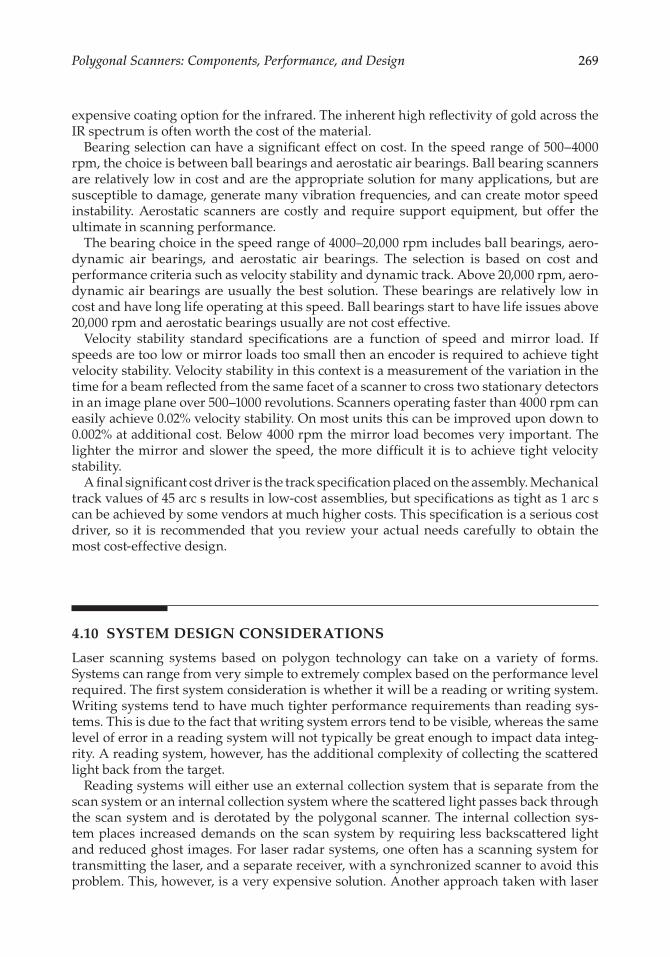
The.optical.system.used.in.laser.scanners.can.be.separated.into.two.generic.types:.pre-objective.and.post-objective..Pre-objective.is.a.term.used.to.describe.the.use.of.a.polygon.to.deflect.a.ray.bundle,.which.after.deflection.is.imaged.by.a.lens.or.curved.mirror.(Figure 4.18)..This.method.of.scanning.places.the.function.of.focal.plane.definition.on.the.lens,.referred.to.as.a.scan.lens,.rather.than.on.the.scanning.facet..Several.desirable.characteristics.can.be.designed.into.the.scan.lens.when.employed.in.pre-objective.scanning..An.example.is.a.lens.design.referred.to.as.F-Theta..An.F-Theta.lens.has.the.following.characteristics:
. 1..A.flat.focal.plane
. 2..Uniform.spot.diameter.over.the.entire.scan
. 3..Linear.spot.velocity.at.the.scan.plane.(assuming.constant.angular.velocity.of.the.polygon)
Usually.it.is.desirable.to.have.the.scanning.spot.move.with.a.highly.accurate.and.constant.velocity.in.the.scan.plane..Polygonal.mirror.deflectors.provide.angular.velocity.stability.in.the.range.0.002%–0.05%,.depending.on.the.speed.and.inertia.of.the.scanner..Without.the.aid.of.an.F-Theta.lens,.however,.the.spot.velocity.variation.on.a.flat.focal.surface.will.be.
TABLE 4.2
List.of.Key.Parameters
Wavelength 350–10,600.nm
Number.of.resolvable.points 100–50,000Spot.size 1.micron–25.mmSpot.size.variation.across.scan ≤5%–15%Scan.length 1.mm–2.mTelecentricity 0.5–30°Bow ≤0.001%.of.scan.line.lengthScan.efficiency 30%–90%Intensity.nonuniformity ≤2%.to.≤10%Pixel.placement.accuracy•. Jitter ≤0.002%.to.≤0.02%•. Cross-scan.error ≤1%.to.≤25%.of.line.spacing
Scatter ≤0.2%.to.≤5%Data.rateLaser.noise.levelsEnvironmental.factors.and.system.interfaces
PolygonalScanners:Components,Performance,andDesign 271
proportional.to.the.tangent.of.the.scan.angle,.which.for.systems.involving.several.degrees.of.scan.means.several.percent.variation.
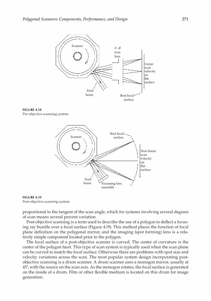
Post-objective.scanning.is.a.term.used.to.describe.the.use.of.a.polygon.to.deflect.a.focus-ing.ray.bundle.over.a.focal.surface.(Figure.4.19)..This.method.places.the.function.of.focal.plane.definition.on.the.polygonal.mirror,.and.the.imaging.(spot.forming).lens.is.a.rela-tively.simple.component.located.prior.to.the.polygon.
The.focal.surface.of.a.post-objective.scanner. is.curved..The.center.of.curvature. is. the.center.of.the.polygon.facet..This.type.of.scan.system.is.typically.used.when.the.scan.plane.can.be.curved.to.match.the.focal.surface..Otherwise.there.are.problems.with.spot.size.and.velocity.variations.across.the.scan..The.most.popular.system.design.incorporating.post-objective.scanning.is.a.drum.scanner..A.drum.scanner.uses.a.monogon.mirror,.usually.at.45°,.with.the.source.on.the.scan.axis..As.the.monogon.rotates,.the.focal.surface.is.generated.on.the.inside.of.a.drum..Film.or.other.flexible.medium.is.located.on.this.drum.for.image.generation.
Scanner
Feedbeam Best focal
surface
Linearscanvelocityonflatsurface
F–θscanlens
FIGURE 4.18Pre-objective.scanning.system.
Scanner
Feedbeam
Best focalsurface
Non-linearscanvelocityonflatsurface
Focussing lensassembly
FIGURE 4.19Post-objective.scanning.system.

272 HandbookofOpticalandLaserScanning
Post-objective. scanning. finds. application. in. very. high-resolution. systems. requiring.greater. than.25,000.points.across.the.scan..Scanners.designed.for. the.prepress. industry.use.this.design.technique.quite.often.
Another.factor.to.consider.when.designing.a.scan.system.is.the.degree.of.telecentric-ity.required..A.system.is.considered.to.be.telecentric.if.the.output.from.the.scan.system.strikes.the.image.plane.at.90°.for.all.points.across.the.scan.line..A.post-objective.scanner.can.be.telecentric.if.the.image.plane.can.be.curved.to.intercept.the.output.from.the.scan-ner..If.a.flat.image.plane.is.required,.a.pre-objective.scan.system.will.need.to.have.a.scan.lens.that.is.slightly.larger.than.the.scan.plane.to.meet.the.telecentric.requirement..This.can.drive.up.the.scan.lens.costs.and.result.in.a.prohibitively.expensive.system..Normally,.some.level.of.deviation.from.telecentricity.is.given.in.a.system.specification.
In.a.writing.application.a.decision.as.to.how.to.use.the.available.polygon.facet.is.needed..Systems.can.either.be.under-.or.overfilled..Underfilled.designs.are.the.most.common.and.do.not.waste.available.laser.energy.because.the.facet.is.sized.such.that.the.beam.footprint.on.the.facet.never.crosses.over.the.edges.of.the.facet.during.the.full.system.scan.angle..On.the.other.hand,.in.an.overfilled.design.the.polygon.facet.is.sized.such.that.the.beam.completely.fills.the.polygon.facet.over.the.entire.full.scan.angle..Underfilled.designs.are.preferred.in.many.applications.because.there.is.less.wasted.energy.and.there.is.minimal.diffraction.from.the.facet.edges..Overfilled.designs.have.the.one.advantage.that.the.system.duty.cycle.can.approach.100%..The.duty.cycle.is.the.ratio.of.the.active.scan.time.to.the.full.facet.time.
4.11 POLYGON SIZE CALCULATION
Once.a.system.concept.is.chosen,.and.the.optical.design.completed,.the.polygon.size.needs.to.be.calculated..A.few.key.parameters.must.be.known.in.order.to.size.the.polygon:
. 1..Scan.angle,.θ
. 2..Beam.feed.angle,.α
. 3..Wavelength,.λ
. 4..Desired.duty.cycle,.C
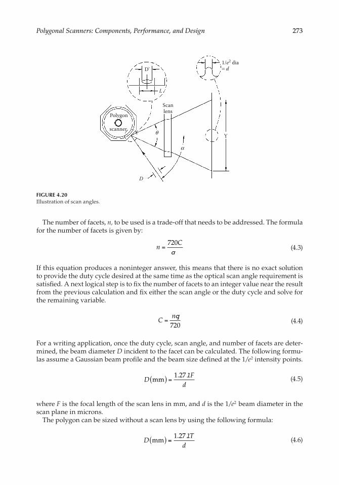
θ is. the. full. extent.of. the.active.scan.measured. in.degrees.as. illustrated. in.Figure.4.20..This.value.is.usually.in.the.range.of.5–70°..α is.the.beam.feed.angle.measured.in.degrees.between.the.input.beam.to.the.polygon.and.the.center.of.the.scan.exiting.the.polygon..It.will.be.cost.effective.to.keep.this.angle.as.small.as.possible.in.order.to.reduce.polygon.size..In.certain.scanner.applications.the.beam.feed.angle.is.zero..The.beam.is.brought.in.through.a.beamsplitter.in.the.center.of.scan.or.at.a.slight.angle.relative.to.the.exiting.scanned.beam..λ.is.the.operating.wavelength.expressed.in.microns.and.to.be.used.in.the.calculation.of.the.beam.size.on.the.polygon.with.a.known.desired.spot.size.in.the.scan.plane..C.is.the.duty.cycle,.which.is.the.ratio.of.active.scan.time.to.total.time..Duty.cycles.in.the.range.of.30%–90%.are.common..However,.the.greater.the.duty.cycle,.the.larger.and.more.costly.the.polygon..With.all.conventional.scan.systems.with.the.exception.of.monogon.drum.scan-ners.some.portion.of.the.time.will.be.spent.transitioning.from.one.facet.to.the.next..We.will.assume.that.the.design.being.considered.is.underfilled..This.means.that.only.one.facet.is.being.used.to.scan.the.image.plane.at.any.given.time.
PolygonalScanners:Components,Performance,andDesign 273
The.number.of.facets,.n, to.be.used.is.a.trade-off.that.needs.to.be.addressed..The.formula.for.the.number.of.facets.is.given.by:
.n
C=
720q . (4.3)
If.this.equation.produces.a.noninteger.answer,.this.means.that.there.is.no.exact.solution.to.provide.the.duty.cycle.desired.at.the.same.time.as.the.optical.scan.angle.requirement.is.satisfied..A.next.logical.step.is.to.fix.the.number.of.facets.to.an.integer.value.near.the.result.from.the.previous.calculation.and.fix.either.the.scan.angle.or.the.duty.cycle.and.solve.for.the.remaining.variable.
.C
n=
q720 . (4.4)
For.a.writing.application,.once.the.duty.cycle,.scan.angle,.and.number.of.facets.are.deter-mined,.the.beam.diameter.D incident.to.the.facet.can.be.calculated..The.following.formu-las.assume.a.Gaussian.beam.profile.and.the.beam.size.defined.at.the.1/e2.intensity.points.
.D
Fd
mm( ) = 1 27. l
.(4.5)
where.F is.the.focal.length.of.the.scan.lens.in.mm,.and.d is.the.1/e2..beam.diameter.in.the.scan.plane.in.microns.
The.polygon.can.be.sized.without.a.scan.lens.by.using.the.following.formula:
.D
Td
mm( ) = 1 27. l
.(4.6)
Polygon
scanner
Scanlens
D
Y
1/e2 dia= d
L
D'
θ
α
FIGURE 4.20Illustration.of.scan.angles.
274 HandbookofOpticalandLaserScanning
where.T is. the.distance. from. the.polygon. to. the. focal. surface. in.mm,.and.d is. the.1/e2.
beam diameter.on.the.focal.surface.in.microns.For.a.reading.system,.D is.a.selected.value.based.on.the.system-limiting.aperture..The.
intensity.profile.across.the.diameter.is.no.longer.Gaussian.but.top.hat.instead.Since.the.size.of.the.facet.depends.on.the.actual.beam.footprint.on.the.facet,.the.feed.angle.
effect.on.D must.be.taken.into.account..The.value.D′ is.the.projected.footprint.on.the.polygon.facet..It.takes.into.account.the.truncation.diameter.and.the.cosine.growth.of.the.beam.on.the.facet.due.to.the.beam.feed.angle..The.formula.for.calculating.the.beam.footprint.is:
.D
Dʹ =
1 52
.cos( / )a
. (4.7)
The.calculations.assume.a.TEM00.Gaussian.beam.that.is.truncated.at.the.1.5.×.1/e2.diam-eter..If.the.application.can.tolerate.more.clipping.at.the.start.and.end.of.scan.the.polygon.size.can.be.reduced.
The. length. of. the. facet. (L). can. be. approximated. from. the. beam. footprint. using. the.following:3
.L
DC
( )mm =ʹ
−1. (4.8)
The.polygon.diameter.can.now.be.approximated.as.follows:
.Diam
tan(180/ )inscribed ⊕L
n . (4.9)
If.the.polygon.diameter.is.too.large.then.there.are.three.options..The.first.is.to.reduce.the.duty.cycle.and.suffer.a.higher.speed.and.burst.data.rate..The.second.is.to.reduce.the.beam.feed.angle..The.third.is.to.allow.more.intensity.variation.across.the.scan.by.reducing.the.1.5.multiplier..This.in.turn,.reduces.the.facet.length.
4.12 MINIMIZING IMAGE DEFECTS IN SCANNING SYSTEMS
In.order.to.design.a.scanning.system.that.accurately.reproduces.information,.knowledge.of.the.types.of.artifacts.that.the.scan.system.can.produce.and.visibility.thresholds.of.these.artifacts.is.needed..The.specifications.required.to.reduce.the.artifacts.to.acceptable.levels.vary. by. application;. for. example,. a. prepress. imager. has. different. requirements. from. a.laser.printer..This.section.is.written.with.writing.applications.in.mind..Many.of.the.defects.associated.with.writing.applications.can.also.be.present.in.reading.applications.
4.12.1 Banding
Banding.is.one.of.the.most.common.scan.artifacts.that.will.show.up.in.scanning.systems..Banding.is.a.periodic.variation.in.the.line-to-line.separation.or.intensity.of.the.output..The.human.eye.is.very.sensitive.to.periodic.errors..The.sensitivity.is.frequency.dependent.and.great.care.must.be.taken.to.ensure.that.scan.errors.in.the.peak.frequency.range.are.mini-mized.4.In.continuous.tone.and.halftone.printers.the.line-to-line.placement.errors.need.to.be.reduced.to.less.than.0.5%.of.the.line.spacing..In.other.applications.this.can.be.as.large.as.10%–20%.before.banding.becomes.visible.

PolygonalScanners:Components,Performance,andDesign 275
The.sources.of.banding.include.reflectivity.variations,.dynamic.track.errors.between.fac-ets,.mechanical.vibrations,.electrical.noise.and.secondary.axis.translation.errors..Polygon.reflectivity.variations.can.be.easily.eliminated.by.properly.specifying.the.polygon.coating.such.that.these.errors.will.not.be.visible..A.specification.of.less.than.1%.variation.of.reflec-tivity.on.all.facets.will.be.adequate.for.all.but.the.most.demanding.applications.
Either.improving.the.polygon.itself.or.compensating.for.the.error.can.reduce.dynamic.track.errors..Either.approach.will.increase.system.costs.so.the.trade-off.between.the.brute.force.approach.of.improving.the.polygonal.scanner.must.be.weighed.against.the.costs.of.additional.system.complexity.
Dynamic. track.error. compensation.can.either. be.active.or.passive..Active. techniques.rely.on.using.an.active.component.to.move.the.beam.to.compensate.for.the.error.whereas.passive.techniques.rely.on.optics.to.minimize.the.errors..Active.correction.techniques.will.compensate.for.repeatable.errors,.but.not.errors.that.vary.throughout.the.scan.line..Passive.techniques.will.compensate.for.both.repeatable.and.nonrepeatable.errors.
Active.correction.techniques.are.usually.based.on.sampling.the.beam.position.errors.perpendicular.to.the.scan.direction.(cross.scan).between.scans.and.applying.a.beam.steer-ing. correction. in. the. system. prior. to. the. polygon. to. change. the. beam. pointing.. These.techniques.are.used.primarily.in.low-speed.systems.due.to.the.frequency.response.limita-tions.of.the.beam.steering.components..Active.correction.systems.are.rare.because.there.is.added.mechanical.complexity,.higher.cost,.and.the.lack.of.correction.for.changes.that.occur.during.scan.
Passive.correction.techniques.are.quite.common.and.the.basic.concept.is.illustrated.in.Figure.4.21..The.polygon.facet.is.reimaged.with.some.magnification.to.the.scan.plane.in.the.cross-scan.axis..A.cylindrical.lens.element.is.typically.used.to.create.a.line.focus.on.the.polygon.facet..The.reimaging.of.this.line.in.the.cross-scan.axis.can.be.accomplished.using.a.variety.of.components..Common.methods.include.using.a.toroidal.element.near.the.polygon,.a.cylindrical.lens.near.the.scan.plane,.or.a.cylindrical.mirror.near.the.scan.plane.5,6.These.passive.methods.will.provide.a.significant.reduction,.but.not.perfect.com-pensation.due.to.pupil.shifting..The.pupil.shift.is.due.to.the.fact.that.the.polygon.rotates.about.its.center.rather.than.rotating.about.the.facet..The.facet.vertex.changes.during.rota-tion.so.the.object.point.moves.in.and.out.as.the.facet.rotates.
Banding.does.not.necessarily.result.from.optical.effects..Other.sources.such.as.vibration.or.electrical.noise.can.contribute.to.banding..Mechanical.vibrations.can.be.introduced.by.the.rotating.device.and.amplified.by.the.scan.system.platform..If.the.platform.is.not.rigidly.coupled.to.the.image.plane,.then.relative.motion.between.the.scanner.and.the.image.can.result.in.a.banding.artifact.
Polygon Cross-scan axis view
Scanlens Cylindrical
lens
Line focuson facet
FIGURE 4.21Passive.cross-scan.correction.

276 HandbookofOpticalandLaserScanning
Electrical.noise.can.be.generated.by.lasers.or.laser.power.supplies..It.can.modulate.the.laser.output.directly.or. it. can.affect. the.performance.of. an.external.modulation. device.such.as.an.acousto-optic.modulator..Continuous.tone.applications.can.be.particularly.sen-sitive.to.electrical.noise..Repeatable.noise.on.the.order.of.0.5%.of.peak.power.can.be.visible..The.electrical.noise.can.appear.to.be.banding.if.the.frequency.is.near.to.or.a.multiple.of.the.revolution.rate.
In.most.scan.systems.the.second.axis.of.the.image.is.controlled.by.a.mechanical.device,.such.as.a.translation.stage,.direct.drive.rollers,.or.a.belt.drive..The.velocity.stability.of.this.second.axis.must.be. specified. to. the. same. level.of. requirements.as. the. scanner.device..Velocity.errors.in.this.second.axis.directly.impact.the.banding.in.the.image.
This.section.has.shown.that.there.are.a.variety.of.sources.of.banding..Care.must.be.taken.in. the.design.phase. to.properly. specify.all. components. that. contribute. to. this.problem.since.it.can.be.difficult.to.isolate.the.root.cause.when.this.defect.appears.in.a.scan.system.
4.12.2 Jitter
Jitter.is.the.high-frequency.variation.in.the.pixel.placement.along.the.scan.direction..Various.systems.can.tolerate.different.levels.of.jitter.before.artifacts.become.visible..Output.scanners.that.place.a.premium.on.pixel.placement.will.typically.require.0.1-pixel.accuracy.whereas.visual.image.outputs.can.tolerate.up.to.1.pixel.in.many.applications..Jitter.has.both.random.and.repeatable.components..Random.jitter.is.visually.less.objectionable.than.periodic.jitter.
Random.jitter.errors.can.be.produced.by.the.ball.bearings.used.in.most.low-speed.scan-ning.systems..The.magnitude.of.these.errors.is.dependent.on.the.inertia.of.the.rotor,.the.ball.bearings.chosen,.and.the.bearing.mounting.method..Errors.are.usually.small.enough.not.to.be.of.concern..Aerostatic.air.bearings.offer.an.alternative.if.the.system.is.sensitive.to.the.ball.bearing.errors.
Motor.cogging.with.brushless.DC.motors.can.also.create.jitter.errors.that.repeat.once.per.revolution..The.motor.controller.can.reduce.these.errors.with.proper.feedback.rates.(encoders.or.start.of.scan.feedback),.but.they.cannot.be.eliminated..One.method.to.over-come.these.errors.in.low-speed.applications.is.to.retime.the.output.data,.based.on.actual.scanner.position. information.provided.by.an.encoder..The.only.way. to.eliminate. these.errors.is.to.find.a.motor.with.zero.cogging.torque..There.is.a.class.of.toothless.motors.that.have.close.to.zero.cogging.torque..They.are.expensive,.but.may.become.more.affordable.as.they.further.penetrate.the.market.
Polygon.facet.flatness.variations.result.in.a.periodic.jitter.with.a.frequency.of.once.per.revolution.or.higher..The.curvature.causes.small.deviations.in.the.angle.of.reflection.from.the.facet..If.the.curvature.of.each.facet.varies,.this.causes.the.time.between.start.of.scan.and.end.of.scan.to.vary..A.special.case.exists.where.there.is.no.contribution.to.jitter.if.all.facets.have.the.same.curvature..A.facet.flatness.specification.on.the.order.of.λ/8.is.adequate.for.most.applications.
Facet.radius.variations.in.systems.using.post-objective.scanning.result.in.beam.displace-ment.in.the.scan.plane.7.A.facet.radius.variation.specification.of.less.than.25.microns.is.acceptable.for.most.scanning.applications.
4.12.3 Scatter and Ghost Images
There. are. many. sources. of. scattered. light. and. ghost. images. in. an. optical. system.. The.majority.of.ghost.images.can.be.controlled.through.proper.coatings.and.the.placement.of.baffles..For.example,.if.the.strays.are.out.of.the.plane.of.the.scanned.image.an.exit.slit.does.
PolygonalScanners:Components,Performance,andDesign 277
a.good.job.of.eliminating.them..Scan.lenses.can.create.problems.with.ghost.images..The.interior.surfaces.in.these.lens.systems.set.up.ghost.images.that.are.difficult.if.not.impossi-ble.to.eliminate.with.baffles..The.antireflection.coatings.need.to.be.high.quality,.reducing.reflections.to.near.zero.
As. mentioned.earlier. in. the. chapter,. the.polygon. surface. can. contribute. to. scatter.. In.extremely.sensitive.applications.a.diamond.turned.surface.may.produce.too.much.scatter..This. type.of.surface.also.produces.a. large.percentage.of.near.angle.scatter. that. is.diffi-cult.to.baffle..A.conventionally.polished.polygon.produces.wide-angle.scatter.and.a.much.lower.magnitude.of.total.integrated.scatter.
If. the.system.contains.an.exit.window.or.has.a. lens.close. to. the.scan.plane,. then. the.cleanliness.of.this.element.is.important..Dust.particles.on.this.element.can.cause.localized.scatter.in.the.scan.plane.since.the.spot.is.typically.small.at.this.point.in.the.optical.system..If.repeated.each.scan,.this.will.result.in.a.line.being.produced.down.the.image.
Adjacent.polygon.facets.tend.to.be.problematic.in.many.systems.where.there.is.signifi-cant.reflection.from.the.target.surface..The.beam.can.find.its.way.back.through.the.system.to.the.next.facet..The.problem.with.this.type.of.stray.light.is.that.it.will.be.on.axis..The.best.solution.is.to.tilt.the.scan.plane.a.few.degrees.relative.to.the.scan.system.so.scan.plane.reflections.are.out.of.plane..Another.solution.is.to.mask.the.polygon.sufficiently.to.leave.only.the.active.scan.aperture.open.
The.time.between.scans.when.the.beam.is.passing.over.the.tips.of.the.polygon.is.another.source.for.scatter..Light.will.scatter.from.the.tips.of.the.polygon.and.from.the.side.of.scan.lens.mounts..Turning.off. the.beam.between.scans.and.using.a. time. interval.counter. to.turn.the.beam.on.just.prior.to.the.start.of.scan.sensor.will.eliminate.this.possible.source.of.problems.
Acousto-optic.modulators.can.produce.several.undesirable.effects..Scatter.from.the.crystal.can.limit.the.extinction.ratio..Long.decay.times.may.result.in.tails.when.transitioning.from.black.to.gray.in.a.continuous.tone.application..The.crystals.used.can.also.suffer.from.sound.field.reflections.that.show.up.as.ghost.images..Working.with.an.application.engineer.at.the.modulator.supplier.is.the.best.way.to.avoid.these.issues.from.affecting.a.scan.system.
4.12.4 Intensity Variation
Variations.in.laser.intensity.can.produce.a.variety.of.image.artifacts.depending.on.the.fre-quency.of.the.variation..A.slowly.varying.fluctuation.is.much.less.objectionable.than.a.high-frequency.variation..Whereas.intensity.variation.on.the.order.of.a.few.percent.may.be.tolerable.over.an.entire.image,.local.intensity.variations.may.need.to.be.controlled.to.less.than.0.5%.
Scan.lens.coatings.and.the.coatings.on.any.other.elements.located.after.the.polygon.can.cause.variations.in.the.scan.plane.intensity.across.the.scan..A.transmission.or.reflection.uniformity.specification.is.needed.to.control.this.variable.
4.12.5 Distortion
Scanning.systems.typically.employ.a.scan.lens.that.has.an.F-theta.characteristic..The.lens.distortion.is.controlled.to.produce.image.height.that.is.proportional.to.the.scan.angle..This.F-theta.characteristic.ensures.linear.scans.with.constant.velocity..These.lenses.are.not.per-fect.but.they.do.reduce.the.nonlinearity.down.to.0.01%–0.1%.range..This.is.adequate.for.all.but.the.most.critical.applications..These.residual.errors.are.repeatable,.therefore;.intensity.compensation.for.dwell.time.differences.or.variable.clocking.schemes.for.pixel.placement.differences.can.be.employed.to.remove.the.residual.error.

278 HandbookofOpticalandLaserScanning
4.12.6 Bow
Bow.is.defined.as.the.variation.from.straightness.of.a.scan.line..Bow.is.usually.a.slowly.varying.function.across.the.scan..A.considerable.amount.of.bow.can.be.tolerated.before.becoming.visually.objectionable..In.most.applications.0.05%.of.the.scan.line.length.of.bow.is.an.adequate.specification..If.the.system.is.designed.to.have.the.beam.brought.in.on.the.same.axis.as.the.scan.then.bow.is.caused.by.the.errors.in.beam.alignment..This.can.nor-mally.be.adjusted.to.very.fine.levels.and.is.therefore.usually.not.a.serious.problem.in.a.polygonal.scan.system..An.equation.for.bow.is.given.by:
.E F=
1−⎡
⎣⎢⎤⎦⎥
sincos
bq
1.
(4.10)
where.F is.the.focal.length.of.the.scan.lens,.E is.the.spot.displacement.as.a.function.of.field.angle,.θ is.the.field.angle,.and.β is.the.angle.between.the.incoming.beam.and.the.plane.that.is.perpendicular.to.the.rotation.axis.8
4.13 SUMMARY
This. chapter. has. covered. the. components,. performance. characteristics,. and. design.approaches.for.polygonal.scanners.and.systems.based.on.these.scanners..This.technology.continues. to. evolve.and. thrives.among. increasing.competition. from.other. technologies.both.in.writing.and.reading.applications..I.fully.expect.that.the.performance.values.that.are.stated.in.this.chapter.will.be.significantly.improved.on.in.the.near.future..However,.the.system.level.artifacts.that.a.system.designer.must.be.careful.to.avoid.tend.to.remain.a.constant..An.in-depth.knowledge.of.these.artifacts.and.their.root.causes.will.help.reduce.development.time.for.new.systems.
ACKNOWLEDGMENTS
The.author.would.like.to.thank.Randy.Sherman.for.his.contributions.to.this.chapter..Steve.Lock.and.Jim.Oschmann.assisted.with.technical.reviews.of.the.chapter.that.were.greatly.appreciated..The.author.would.also.like.to.thank.Luis.Gomez.of.Lincoln.Laser.Company.for.providing.the.illustrations.and.Steven.Stewart.for.the.cover.art..Photographs.are.cour-tesy.of.Lincoln.Laser.Company.
REFERENCES
. 1.. Oberg,.E..Machinery’s Handbook, 23rd.Ed;.Industrial.Press:.New.York,.1988;.196.
. 2.. Bennett,. J.M.;.Mattsson,.L..Introduction to Surface Roughness and Scattering; Optical.Society.of.America:.Washington,.DC,.1989;.50–52.
. 3.. Beiser,. L.. Design. equations. for. a. polygon. laser. scanner.. In. Beam Deflection and Scanning Technologies; Marshall,.G.F.,.Beiser,.L.,.Eds;.Proc. SPIE.1454;.1991;.60–65.

PolygonalScanners:Components,Performance,andDesign 279
. 4.. Bestenreiner,.F.;.Greis,.U.;.Helmberger,.J.;.Stadler,.K..Visibility.and.corrections.of.periodic.inter-ference.structures.in.line-by-line.recorded.images..J. Appl. Phot. Eng..1976, 2,.86–92.
. 5.. Fleischer,.J..Light.Scanning.and.Printing.Systems..US.Patent.3,750,189,.July.1973.
. 6.. Brueggemann,.H..Scanner.with.reflective.pyramid.error.compensation..US.Patent.4,247,160,.January.1981.
. 7.. Horikawa,.H.;.Sugisaki,.I.;.Tashiro,.M..Relationship.between.fluctuation.in.mirror.radius.(within.polygon).and.the.jitter..In.Beam Deflection and Scanning Technologies; Marshall,.G.F.,.Beiser,.L.,.Eds;.Proc. SPIE 1454;.1991;.46–59.
. 8.. Hopkins,. R.;. Stephenson,. D.. Optical. systems. for. laser. scanners.. In. Optical Scanning; Marcel.Dekker:.New.York,.1991;.46.