handbook - rgb.be
TRANSCRIPT
0-004-7799-1 (EN), 2001-11-19
TAC Xenta® 110-DHandbook


TAC Xenta 110-D Handbook Preface
3 (80), 0-004-7799-1 (EN) TAC AB, 2001-11-19
PrefaceWelcome to the handbook of the TAC Xenta 110-D.
If you should discover errors and/or unclear descriptions in this manual,please contact your TAC representative. You may also send e-mail [email protected]
This document, as well as the product it refers to, is only intended forlicensed users of the product and the document. TAC AB owns thecopyright of this document and reserves the right to make changes,additions or deletions. TAC AB assumes no responsibility for possiblemistakes or errors that might appear in this document.
Do not use the product for any other purposes than those indicated inthis document.
Only licensed users of the product and the document are permitted touse the document or any information therein. Distribution, disclosure,copying, storing or use of the product, the information or the illustra-tions in the document on the part of non-licensed users, in electronic ormechanical form, as a recording or by other means, including photoco-pying or information storage and retrieval systems, without the expresswritten permisson of TAC AB, will be regarded as a violation of copy-right laws and is strictly prohibited.
TAC Xenta are registered trademarks of TAC AB in Sweden and othercountries. All other brand names are trade marks of their respectiveowners.

TAC Xenta 110-D Handbook Preface
TAC AB, 2001-11-19 0-004-7799-1 (EN), 4 (80)
Revisions
Part number Comments Author Date
0-004-7799-0 First edition. SUWA 2001-08-14
0-004-7799-1 Second edition. Sun blinds edited. New section (2.8)about lamp loads.
SUWA 2001-11-19

TAC Xenta 110-D Handbook
TAC AB, 2001-11-19 0-004-7799-1(EN), 5 (80)
Contents
Preface ..................................................................................................................................... 3
1 Introduction .......................................................................................................................... 71.1 The content of the handbook .......................................................................................................................... 7
1.2 Documentation ................................................................................................................................................. 8
1.3 Terminology ..................................................................................................................................................... 9
2 Applications ......................................................................................................................... 112.1 General ............................................................................................................................................................ 11
2.2 Two rooms controlled by one TAC Xenta 110-D ........................................................................................ 12
2.2.1 Without locally connected occupancy sensors ............................................................................................. 122.2.2 With locally connected occupancy sensors .................................................................................................. 132.2.3 With locally connected occupancy sensors and wall modules ..................................................................... 142.2.4 With networked wall module or ScreenMate ............................................................................................... 15
2.3 One room controlled by one TAC Xenta 110-D .......................................................................................... 16
2.3.1 With light level control ................................................................................................................................. 162.3.2 With lux-sensor and light level control ......................................................................................................... 172.3.3 With networked wall module or ScreenMate ............................................................................................... 18
2.4 One room controlled by one TAC Xenta 110-D and one TAC Xenta 10x ................................................ 19
2.5 Flexible solutions with master/slave ............................................................................................................. 20
2.5.1 With two TAC Xenta 110-D ......................................................................................................................... 202.5.2 With one TAC Xenta 110-D ......................................................................................................................... 21
2.6 Wall modules .................................................................................................................................................. 22
2.7 ScreenMate ..................................................................................................................................................... 23
2.8 Lamp loads ..................................................................................................................................................... 24
3 Installation ........................................................................................................................... 253.1 Mechanical installation .................................................................................................................................. 25
3.1.1 Fitting ............................................................................................................................................................ 25
3.2 Electrical installation ..................................................................................................................................... 27
3.2.1 General .......................................................................................................................................................... 273.2.2 Wiring of TAC Xenta 110-D/24 .................................................................................................................. 293.2.3 Wiring of TAC Xenta 110-D/115 ................................................................................................................ 303.2.4 Wiring of TAC Xenta 110-D/230 ................................................................................................................ 313.2.5 How to connect the TAC Xenta OP to the wall module ............................................................................... 32
3.3 Commissioning ............................................................................................................................................... 34
3.3.1 General .......................................................................................................................................................... 343.3.2 Node status .................................................................................................................................................... 343.3.3 Configuration parameters (nci’s) .................................................................................................................. 353.3.4 Network installation ...................................................................................................................................... 353.3.5 Network variable binding ............................................................................................................................. 363.3.6 Network variable preservation ...................................................................................................................... 363.3.7 Function test .................................................................................................................................................. 36
3.4 Configuration parameters ............................................................................................................................. 37
3.4.1 nciAppOptions .............................................................................................................................................. 37

TAC Xenta 110-D Handbook
6 (80), 0-004-7799-1 (EN) TAC AB, 2001-11-19
3.4.2 nciAppOptions2 ............................................................................................................................................38
4 Operation .............................................................................................................................414.1 General ............................................................................................................................................................41
4.2 Alarm ...............................................................................................................................................................42
4.3 Problems and solutions ..................................................................................................................................43
5 Functional description ........................................................................................................455.1 General ............................................................................................................................................................45
5.2 Space Comfort controller, SCC ....................................................................................................................46
5.2.1 Occupancy modes .........................................................................................................................................465.2.2 Zone temperature control ..............................................................................................................................485.2.3 Heating and cooling control ..........................................................................................................................50
5.3 Lamp actuators, LA .......................................................................................................................................52
5.4 Constant light control, CLC ..........................................................................................................................54
5.5 More about functions .....................................................................................................................................57
5.5.1 Occupancy sensor ..........................................................................................................................................575.5.2 Minimum heat output, nciHeatPrimMin .......................................................................................................585.5.3 Master/slave operation ..................................................................................................................................58
6 Communication ...................................................................................................................616.1 General ............................................................................................................................................................61
6.2 Default settings and power on .......................................................................................................................62
6.3 Updating network variables, Heartbeat .......................................................................................................62
6.4 Not accepted values ........................................................................................................................................62
6.5 The node object ..............................................................................................................................................63
6.5.1 The node object’s inputs (nvi) .......................................................................................................................636.5.2 The node object’s outputs (nvo) ....................................................................................................................646.5.3 The node object’s configuration parameters (nci) ........................................................................................64
6.6 Lamp actuator object .....................................................................................................................................65
6.6.1 The lamp actuator object’s inputs (nvi) ........................................................................................................656.6.2 The lamp actuator object’s outputs (nvo) ......................................................................................................65
6.7 The constant light controller object ..............................................................................................................66
6.7.1 The constant light controller object’s inputs (nvi) ........................................................................................666.7.2 The constant light controller object’s outputs (nvo) .....................................................................................676.7.3 The constant light controller object’s configuration parameters (nci) ..........................................................67
6.8 The space comfort controller object .............................................................................................................68
6.8.1 The space comfort controller’s inputs (nvi) ..................................................................................................696.8.2 The space comfort controller’s outputs (nvo) ...............................................................................................706.8.3 The controller object’s configuration parameters (nci)) ...............................................................................71
Appendix A: Technical data ................................................................................................73
Appendix B: Commissioning protocol ................................................................................75

TAC Xenta 110-D Handbook Introduction
TAC AB, 2001-11-19 0-004-7799-1 (EN), 7 (80)
1 Introduction1.1 The content of the handbook
Chapter 1 Introduction,
gives an overview over the structure of this handbook, additional infor-mation about the product, and has a short terminology section.
Chapter 2 Applications,
describes different applications for the TAC Xenta 110-D.
Chapter 3 Installation,
contains instructions on mechanical and electrical installation of thecontroller, instructions on commissioning and network installation anddescribes the setting of the zone controller’s configuration parameters.
Chapter 4 Operation,
contains an overview of alarms and some troubleshooting.
Chapter 5 Functional description,
gives detailed information about the zone controller’s basic functions,operating modes and other functions.
Chapter 6 Communication,
describes the zone controller’s communication with other units via thenetwork by means of network variables.
Appendix A, Technical data
lists all technical data and dimensions for TAC Xenta 110-D.
Appendix B, Commissioning protocol
contains a commissioning protocol, which can be used together withchapter 3 during installation and commissioning.
Index
are in the end of the handbook. Use the index to make your search forinformation easier, and the reply form to let us know whether there issomething wrong or unclear in this handbook.
TAC Xenta 110-D Handbook Introduction
8 (80), 0-004-7799-1 (EN) TAC AB, 2001-11-19
1.2 DocumentationEnclosed documentation
TAC Xenta 110-D is delivered with an installation instruction for eachof the variations of TAC Xenta 110-D:
• TAC Xenta 110-D/24,Installation instruction, part number 0FL-3985
• TAC Xenta 110-D/115,Installation instruction, part number 0FL-4002
• TAC Xenta 110-D/230,Installation instruction, part number 0FL-4003
Other documentation
There is additional information about TAC Xenta 110-D in the follo-wing documents:
• Data sheet for TAC Xenta 110-D,part number 0-003-2057
• Data sheet for ZS 101-ZS 105,part number 0-003-1661. Here the wall modules are described.
• TAC Xenta Network Guide,part number 0-004-7460. Here you can find additional informationon network installation.
• TAC Xenta OP Handbook,part number 0-004-7506. Here you will find information on how touse TAC Xenta OP together with TAC Xenta 110-D and the wallmodules.
• TAC Xenta, Zone System Guidelinespart number 0-004-7637. Here you will find information on how thezone system is built with TAC Xenta-components.
• TAC Xenta and LonMaker for Windowspart number 0-004-7775. Here you will find information on how touse LonMaker together with TAC Xenta.
All the above mentioned documents can be found on the internet atwww.tac-global.com or can be ordered from your nearest TAC serviceprovider.

TAC Xenta 110-D Handbook Introduction
TAC AB, 2001-11-19 0-004-7799-1 (EN), 9 (80)
1.3 TerminologyIn this handbook there are some abbreviations and terms which are spe-cific for the zone controller’s applications and network communication.Therefore, the most common terms have been gathered, together with ashort explanation, in the list below.
CLC Constant Light Controller
HF unit High Frequency unit (for electronic light con-trol) without dimming capability
HFD As above but with dimming capability
LA Lamp Actuator
LON Local Operating Network - communicationconcept from Echelon
LNS LonWork Network Services; system tool usedfor installation, configuration and maintenanceof a LonWorks network
ncixxx configuration parameter; variable which gets itsvalue from another unit on the network andkeep it during a power failure
neuron communication processer with built-in protocol
NO/NC Normally Open/Normally Closed
node communication unit on the network
nvixxx variable which gets its value from another uniton the network
nvoxxx variable which sends its value to another unit onthe network
PWM Pulse Width Modulation
service pin useful function for locating controller duringcommissioning
SCC Space Comfort Controller object
SCPT Standard Configuration Properties
SNVT Standard Network Variable Type
wink confirmation of the connection to a specificcontroller via the network (a light-emittingdiode is lit for about 10 seconds)

TAC Xenta 110-D Handbook Introduction
10 (80), 0-004-7799-1 (EN) TAC AB, 2001-11-19

TAC Xenta 110-D Handbook Applications
TAC AB, 2001-11-19 0-004-7799-1 (EN), 11 (80)
2 Applications2.1 General
The applications shown in this chapter are intended to give examples ofthe possibilities with TAC Xenta 110-D.
The zone controller TAC Xenta 110-D is intended for cost effective so-lutions for climate and light control in one or two rooms.
This is achieved by using the 7 LonMark objects (described in chapter6) in different combinations. There are:
• 4 Lamp Actuator objects
• 1 Constant Light Controller objects
• 2 Space Comfort Controller objects
The lamp outputs are intended for one or two HF-equipped lamps in atypical office room. In larger rooms with several lamps, conferencerooms etc, external relays must be used.
The TAC Xenta 110-D controller has,
• climate control with four triac outputs for heating/cooling valves,with possibility for master/slave operation
• light group control with four relay outputs
• an input R1 for use as a dimmer, toggle switch or for temperaturesetpoint adjustment
• inputs X1-X3 for use as light switcher, bypass or occupancy inputs
• an input U1 for use as a lux-level input, digital input (same as X1-X3) or for temperature setpoint adjustment.
For more detailed information, refer to chapter 5, functional description.
The controller comes in three variations for different voltages:TAC Xenta 110-D/24, 110-D/115 and 110-D/230.

TAC Xenta 110-D Handbook Applications
12 (80), 0-004-7799-1 (EN) TAC AB, 2001-11-19
2.2 Two rooms controlled by one TAC Xenta 110-D
2.2.1 Without locally connected occupancy sensorsControlling heating and cooling in sequence using thermal actuators(on/off). Setpoint adjustment and operation mode (occupancy) is set vianetwork variables. Bypass is performed with the light switches.
• Space temperature sensor (input B1 and B2).
• Light switches (inputs X1-3 and U1): Choice of toggle switch disa-bled/enabled in bit 0-3 in nciAppOptions2.
• Choice of toggle switch/bypass disabled/enabled in bits 2-9 in nci-AppOptions.
• Light actuators (outputs K1-4): Choice if power up status off/on inbit 4-7 in and how occupancy detection will affect light in bit 8-11in nciAppOptions2.
• Heating/cooling valves, actuators (outputs V1-V4): Choice of actu-ators NC/NO in bit 13 in nciAppOptions2.
It is possible to use the occupancy sensor for light control by interope-ration between node objects. The network variables can be bound as infigure 2.2:
TAC Xenta110-D
Space tempe-rature sensor
Light switch 1
Light switch 2
Light 1
Light 2
Cooling valve
Heating valve
Space tempe-rature sensor
Light switch 1
Light switch 2
Light 1
Light 2
Cooling valve
Heating valve
Room 1 Room 2
Figure 2.1 Two rooms without occupancy sensors
TAC Xenta 110-D Handbook Applications
TAC AB, 2001-11-19 0-004-7799-1 (EN), 13 (80)
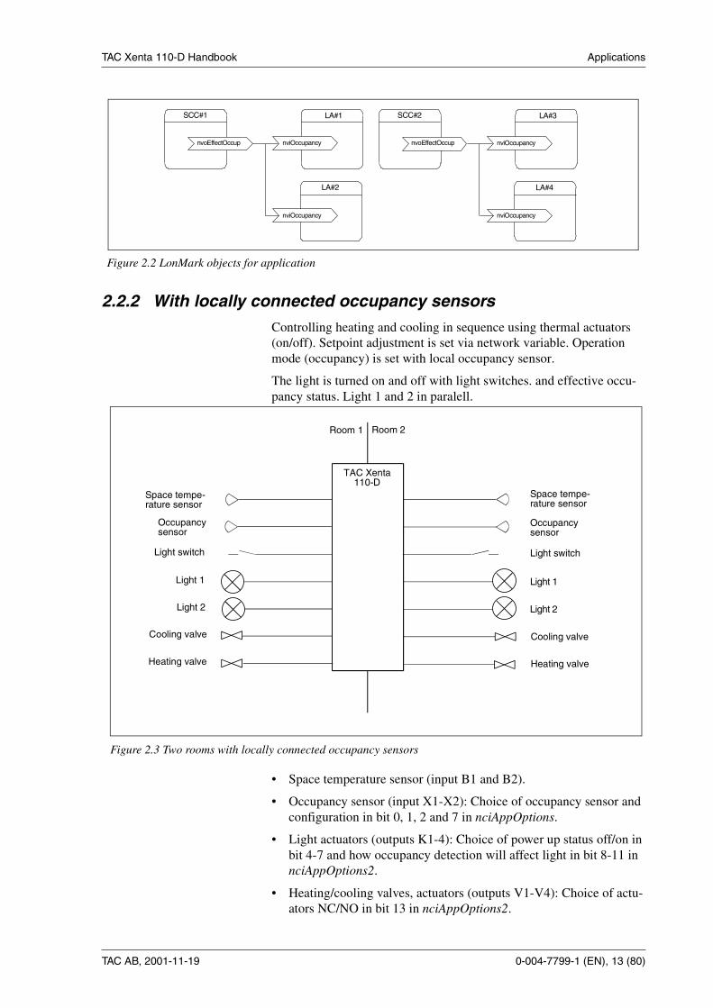
2.2.2 With locally connected occupancy sensorsControlling heating and cooling in sequence using thermal actuators(on/off). Setpoint adjustment is set via network variable. Operationmode (occupancy) is set with local occupancy sensor.
The light is turned on and off with light switches. and effective occu-pancy status. Light 1 and 2 in paralell.
• Space temperature sensor (input B1 and B2).
• Occupancy sensor (input X1-X2): Choice of occupancy sensor andconfiguration in bit 0, 1, 2 and 7 in nciAppOptions.
• Light actuators (outputs K1-4): Choice of power up status off/on inbit 4-7 and how occupancy detection will affect light in bit 8-11 innciAppOptions2.
• Heating/cooling valves, actuators (outputs V1-V4): Choice of actu-ators NC/NO in bit 13 in nciAppOptions2.
LA#2
SCC#1
nviOccupancy
LA#1
nviOccupancy
nvoEffectOccup
LA#4
SCC#2
nviOccupancy
LA#3
nviOccupancy
nvoEffectOccup
Figure 2.2 LonMark objects for application
TAC Xenta110-D
Space tempe-rature sensor
Light switch
Space tempe-rature sensor
Light switch
Light 1
Room 1 Room 2
Occupancysensor
Light 1
Cooling valve
Heating valve
Light 2
Cooling valve
Heating valve
Light 2
Occupancysensor
Figure 2.3 Two rooms with locally connected occupancy sensors

TAC Xenta 110-D Handbook Applications
14 (80), 0-004-7799-1 (EN) TAC AB, 2001-11-19
It is possible to use the occupancy sensor for light control by interope-ration between node objects. The network variables can be bound as infigure 2.4:
2.2.3 With locally connected occupancy sensors and wall modules
Controlling heating and cooling in sequence using thermal actuators(on/off). Setpoint adjustment is set via wall modules. Operation mode(occupancy) is set with local occupancy sensor.
The light is turned on and off with light switches and effective occupan-cy status.
• Space temperature sensor (input B1 and B2).
• Setpoint adjustment (input R1 and U1).
• Occupancy sensor (input X1-X2): Choice of occupancy sensorinput configuration in bit 0, 1, 2 and 7 in nciAppOptions.
SCC#1
nviOccupancy1
LA#1
nvoLampValueFb1
nviLampValue2
LA#2
nvoEffectOccup
Figure 2.4 Interoperability between objects
TAC Xenta110-D
Light switchLight
Cooling valve
Heating valve
Light switchLight 1
Cooling valve
Heating valve
Room 1 Room 2
Occupancysensor
Light
Space tempe-rature sensor
Wall moduleSetpointadjustment
Occupancysensor
Space tempe-rature sensor
Setpointadjustment
Wall module
Light 2
Figure 2.5 Two rooms with locally connected occupancy sensors

TAC Xenta 110-D Handbook Applications
TAC AB, 2001-11-19 0-004-7799-1 (EN), 15 (80)
• Light actuators (outputs K1-K4): Choice of power up status off/onin bit 4-7 and how occupancy detection will affect light in bit 8-11in nciAppOptions2.
• Heating/cooling valves, actuators (outputs V1-V4): Choice of actu-ators NC/NO in bit 13 in nciAppOptions2.
2.2.4 With networked wall module or ScreenMateTo be able to set the setpoint adjustment locally there must be a Lon-Works-based wall module or a ScreenMate installed. A LonWorks ba-sed wall module can enable functions like space temperature sensor,setpoint adjustment, bypass button, occupancy sensor, light switchesand more.
If ScreenMate is used, a local space temperature sensor must be used al-so. Setpoint adjustment, bypass button and light switches can be hand-led from the ScreenMate.
• Space temperature sensor (input B2).
• Light actuators (outputs K1-4): Choice if power up status off/on inbit 4-7 and how occupancy detection will affect light in bit 8-11 innciAppOptions2.
• Heating/cooling valves, actuators (outputs V1-V4): Choice of actu-ators NC/NO in bit 13 in nciAppOptions2.
• Wall module (section 2.6) or ScreenMate (section 2.7).
TAC Xenta110-D
Space tempe-rature sensor
Cooling valve
Heating valve
Space tempe-rature sensor
Light 1
Cooling valve
Heating valve
Room 1 Room 2Wall module ScreenMate
Light 2
Light 1
Light 2
Figure 2.6 Two rooms with networked wall module or ScreenMate

TAC Xenta 110-D Handbook Applications
16 (80), 0-004-7799-1 (EN) TAC AB, 2001-11-19
2.3 One room controlled by one TAC Xenta 110-D
2.3.1 With light level controlControlling heating and cooling in sequence using thermal actuators(on/off). Setpoint adjustment and operation mode (occupancy) is set vianetwork variable. Bypass is performed with the light switches.
The three lights are toggled with the light switches when in occupancymode and turned off in standby and unoccupied mode. Two of the lightsare also light-level controlled with a 1-10 V signal for HFD units. A luxsensor and an NV input (lux setpoint) determine the light level.
A switch is also connected for toggling the CLC output between 10%,100% and controlling the light level.
Auxiliary units (such as relays, fans ,sun blinds) are controlled via net-work variables and requires the SCC object to be configured for slavemode. The nvi:s get their values from another LON device.
• Lux sensor (input U1): set bit 10 to 0 / bit 11 to 1 in nciAppOptions.
• Space temperature sensor (input B1).
• Light switches (inputs X1-3): Set to toggle switches enabled in bit0-2 in nciAppOptions2.
• Toggle switch (input R1): Set bits 12 and 15 in nciAppOptions2 to1. Alternative: Light SP adjustment (input R1): Set bits 12 to 0 and15 to 1 in nciAppOptions2.
• Light actuators (outputs K1-3): Choice if power up status off/on inbit 4-6 and how occupancy detection will affect light in bit 8-10 innciAppOptions2.
• Heating/cooling valves, actuators (outputs V1-V2): Choice of actu-ators NC/NO in bit 13 in nciAppOptions2.
• Auxiliary units (output V3-4): Use master/slave mode, enable slavemode in bit 13 in nciAppOptions. Dependant on the cycle time ofthe controller, 4 seconds.
TAC Xenta110-D
Cooling valve
Heating valve
Lux sensor
Auxiliary unit
Light 3
Light 2
Light 1
HFD (1-10 V)
Light switch 1
Light switch 2
Light switch 3
CLC toggle switch orlight SP adjustment
Space tempe-rature sensor
Figure 2.7 One room with light level control

TAC Xenta 110-D Handbook Applications
TAC AB, 2001-11-19 0-004-7799-1 (EN), 17 (80)
2.3.2 With occupancy sensor and light level control
Heating and cooling is controlled in sequence using thermal actuators(on/off). Setpoint adjustment and operation mode is set locally.
Lights 1 and 2 are toggled with light switches 1 and 2 when in occupu-ied mode, and they are off in standby and unoccupied mode. Light 3 iscontrolled by network variables in occupied mode, and off in standbyand unoccupied mode. Two of the lights are also light-level controlledwith a 1-10 V signal for HFD units. A lux sensor and an NV input(nciLuxSetpoint) determines the light level.
• Lux sensor (input U1): set bit 10 to 0 and bit 11 to 1 in nciAppOp-tions.
• Occupancy sensor (input X1): Set occupancy sensor input to enab-led in bits 0 and 2 in nciAppOptions.
• Space temperature sensor (input B1).
• Setpoint adjustment (input R1): Set bit 15 in nciAppOptions2 to 0.
• Light switches (inputs X2-3): Choice of toggle switch disabled/ena-bled in bit 1-2 in nciAppOptions2.
• Light actuators (outputs K2-4): Choice if power up status off/on inbit 5-7 and if occupancy detection will affect light in bit 8-10 innciAppOptions2.
• Heating/cooling valves, actuators (outputs V1-V4): Choice of actu-ators NC/NO in bit 13 in nciAppOptions2.
TAC Xenta110-D
Cooling valve
Heating valve
Lux sensor
Light 3
Light 2
Light 1
HFD (1-10 V)
Light switch 1
Light switch 2
Space tempe-rature sensor
Occupancy sensor
Temperature set-point adjustment
Figure 2.8 One room with lux-sensor and light level control

TAC Xenta 110-D Handbook Applications
18 (80), 0-004-7799-1 (EN) TAC AB, 2001-11-19
2.3.3 With networked wall module or ScreenMate
Similar to the application in preceding section except for the use of aLonWorks-based wall module or ScreenMate.
• Lux sensor (input U1): set bit 10 to 0 and bit 11 to 1 in nciAppOp-tions.
• Light actuators (outputs K1-3): Choice if power up status off/on inbit 4-6 and how occupancy detection will affect light in bit 8-10 innciAppOptions2.
• Heating/cooling valves, actuators (outputs V1-V2): Choice of actu-ators NC/NO in bit 13 in nciAppOptions2.
• Wall module (section 2.6) or ScreenMate (section 2.7).
• Space temperature sensor (wall module).
TAC Xenta110-D
Space tempe-rature sensor
Cooling valve
Heating valve
Light 3
Wall module
Lux sensor
Light 2
Light 1
HFD (1-10 V)
Figure 2.9 One room with networked wall module or ScreenMate

TAC Xenta 110-D Handbook Applications
TAC AB, 2001-11-19 0-004-7799-1 (EN), 19 (80)
2.4 One room controlled by one TAC Xenta 110-Dand one TAC Xenta 10x
For more advanced demands the TAC Xenta 110-D can work togetherwith a TAC Xenta 101, TAC Xenta 102, TAC Xenta 103 or TAC Xenta104 and still be a very competetive solution.
The application below (figure 2.9) shows a combination with TAC Xe-nta 102-ES (VAV) and TAC Xenta 110-D, but there are many possibil-ties. The interaction between the TAC Xenta 102-ES and TAC Xenta110-D is the operation mode (occupied mode). The window contact canbe used to control auxiliary units when a window is opened.
• Lux sensor (input U1): set bit 10 to 0 / bit 11 to 1 in nciAppOptions.
• Dimmer (input R1): set bit 12 to 0 in nciAppOptions2.
• Light switches (inputs X1-3): Choice of toggle switch disabled/ena-bled in bit 0-2 in nciAppOptions2.
• Light actuators (outputs K1-3): Choice if power up status off/on inbit 4-6 and if occupancy detection will turn light off/on in bit 8-10in nciAppOptions2.
• Auxiliary units (output V3-4): Use master/slave mode, enable slavemode in bit 13 in nciAppOptions. Dependant on the cycle time ofthe controller, 4 seconds.
• Wall module with occupancy sensor and CO2-sensor.
• LON panel bound to nviSetting.
TAC Xenta110-D
Lux sensor
Auxiliary unit
Light 3
Light 2
Light 1
HFD (1-10 V)
Light switch 1
Light switch 2
Light switch 3
TAC Xenta102-ES
Occupancy sensor
Heating valve
VAV boxIncreasedamperDecreasedamper
Wall moduleCO2 sensor
Spacetemp.Setpoint adj.
Bypass button
Mode indicator
Window contact
Increase/decrease signalsLON-panel for lightsetpoint adjustment
I
0
Figure 2.10 One room with one TAC Xenta 110-D and one TAC Xenta 102-ES

TAC Xenta 110-D Handbook Applications
20 (80), 0-004-7799-1 (EN) TAC AB, 2001-11-19
2.5 Flexible solutions with master/slave
2.5.1 With two TAC Xenta 110-DA room is divided into several zones with individual functions or as partof a bigger room, for example in a building with movable walls.
This application has two TAC Xenta 110-D, with one as master and theother as slave. If the room gets divided in two, the slave is configured tobe a master and have a wall module and an occupancy sensor connectedto it.
• Master/slave operation: choice of slave mode disabled/enabled inbit 12 and bit 13 in nciAppOptions.
• Lux sensor (input U1): set bit 10 to 0 and bit 11 to 1 in nciAppOp-tions.
• Light actuators (outputs K1-3): Choice if power up status off/on inbit 4-6 and how occupancy detection will affect light in bit 8-10 innciAppOptions2.
TAC Xenta110-D
Cooling valve
Heating valve
Light 3
Lux sensor
Light 2
Light 1
HFD (1-10 V)
TAC Xenta110-D
Cooling valve
Heating valve
Light 3
Lux sensor
Light 2
Light 1
HFD (1-10 V)
Master
Slave
Occupancysensor
SCC#1
Space tempe-rature sensor
Wall moduleSetpointadjustment
SCC#2
Figure 2.11 One room with two TAC Xenta 110-D as master/slave

TAC Xenta 110-D Handbook Applications
TAC AB, 2001-11-19 0-004-7799-1 (EN), 21 (80)
• Heating/cooling valves, actuators (outputs V1-V4): Choice of actu-ators NC/NO in bit 13 in nciAppOptions2.
• Auxiliary units (output V3-4): Use master/slave mode, enable slavemode in bit 13 in nciAppOptions. Dependant on the cycle time ofthe controller, 4 seconds.
• Space temperature sensor (wall module, section 2.6).
2.5.2 With one TAC Xenta 110-D
The separate objects (controllers) inside of TAC Xenta 110-D can beused as master/slave.
Another option is to use a TAC Xenta 400 as a master to several slaves.In one TAC Xenta 400 there may be several masters.
• Master/slave operation: choice of slave mode disabled/enabled inbit 12 and bit 13 in nciAppOptions.
• Space temperature sensor (input B1 and B2).
• Light switches (inputs X1-3 and U1): Choice of toggle switch disa-bled/enabled in bit 0-3 in nciAppOptions2.
• Light actuators (outputs K1-4): Choice if power up status off/on inbit 4-7.
• Heating/cooling valves, actuators (outputs V1-V4): Choice of actu-ators NC/NO in bit 13 in nciAppOptions2.
Figure 2.12 Four zones divided into rooms controlled with two TAC Xenta 110-D in master/slave configuration
TAC Xenta110-D
Space tempe-rature sensor
Light switch
Light
Cooling valve
Heating valve
Space tempe-rature sensor
Light switch
Light
Cooling valve
Heating valve
TACXenta110-D
Space tempe-rature sensor
Light switch
Light
Cooling valve
Heating valve
Space tempe-rature sensor
Light switch
Light
Cooling valve
Heating valveMaster
Master
Slave
Slave
Room 1
Room 2

TAC Xenta 110-D Handbook Applications
22 (80), 0-004-7799-1 (EN) TAC AB, 2001-11-19
2.6 Wall modulesIt is possible to use a wall module from the ZS 100 (ZS101-ZS104) se-ries, which measures the temperature, together with the TAC Xenta110-D. On the wall module (figure 2.13) there are a setpoint knob anda bypass button with setting possibilities.
NOTE: TAC Xenta 110-D does not support the LED indicator foundon the ZS100 series.
The setpoint knob is used to adjust the zone temperature setpoint with amaximum of ±3 °C (±5 °F).
The bypass button is used to change the operating mode, and by pres-sing the key, an internal timer in the controller, which runs for a specifictime (configurable), is started. Read more about different operating mo-des and ways to force the controller in chapter 5.
Note! The TAC Xenta OP is normally connected directly to the control-ler, not the wall module. The TAC Xenta 110-D has a TAC Xenta OPaccess connecter (type RJ-10) on the controller instead of dedicated ter-minals.
There is additional information on the wall modules and how the tem-peratures can be adjusted locally in the zone by means of the keys in"Data sheet for ZS 101-ZS 105", part number 0-003-1661.
COMFORTECONOMYOFF
Locking screw
Bypass button
Setpoint knob
Temperature sensor
Figure 2.13 Wall module in the ZS100 series
TAC Xenta 110-D Handbook Applications
TAC AB, 2001-11-19 0-004-7799-1 (EN), 23 (80)
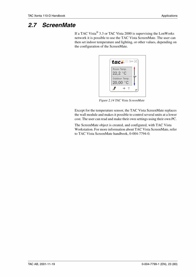
2.7 ScreenMateIf a TAC Vista® 3.3 or TAC Vista 2000 is supervising the LonWorksnetwork it is possible to use the TAC Vista ScreenMate. The user canthen set indoor temperature and lighting, or other values, depending onthe configuration of the ScreenMate.
Except for the temperature sensor, the TAC Vista ScreenMate replacesthe wall module and makes it possible to control several units at a lowercost. The user can read and make their own settings using their own PC.
The ScreenMate object is created, and configured, with TAC VistaWorkstation. For more information about TAC Vista ScreenMate, referto TAC Vista ScreenMate handbook, 0-004-7794-0.
Figure 2.14 TAC Vista ScreenMate

TAC Xenta 110-D Handbook Applications
24 (80), 0-004-7799-1 (EN) TAC AB, 2001-11-19
2.8 Lamp loadsThe relay outputs in TAC Xenta 110-D are only suitable for modernlamp devices equipped with HF or HFD units.
Maximum lamp load
A maximum of 250W lamp loads is recommended for each relay outputto ensure a long relay life time. The limiting factor is the transients ofthe power-up current.
Note: Conventional old fluorescent lamps suffer from severe power-upcurrent transients and should not be used with the controller’s relays.Use external relays instead.
Maximum resistive load
If there is a need to connect something other than lamps (relays etc.), thetotal resistive load per relay must be less than 3 A.

TAC Xenta 110-D Handbook Installation
TAC AB, 2001-11-19 0-004-7799-1 (EN), 25 (80)
3 Installation3.1 Mechanical installation
3.1.1 Fitting
TAC Xenta 110-D can either be snapped onto a DIN rail (figure 3.1) orfastened with two screws to a level surface (figure 3.2). It should alwaysbe fitted into a cabinett or other protective enclosure to fulfill the elec-trical safety requirements.
To fasten the controller onto a DIN rail:
1 Place the controller on the top of the rail as is shown byarrow 1.
2 Turn the controller downwards until it snaps onto the rail as is indi-cated by arrow 2.
3 To remove, place a screwdriver in the lock on the bottom of the con-troller and pull down. It is then possible to lift the controller diago-nally upwards and off the rail..
Figure 3.1 TAC Xenta 110-D fastened on a DIN rail
TAC Xenta 110-D Handbook Installation
26 (80), 0-004-7799-1 (EN) TAC AB, 2001-11-19
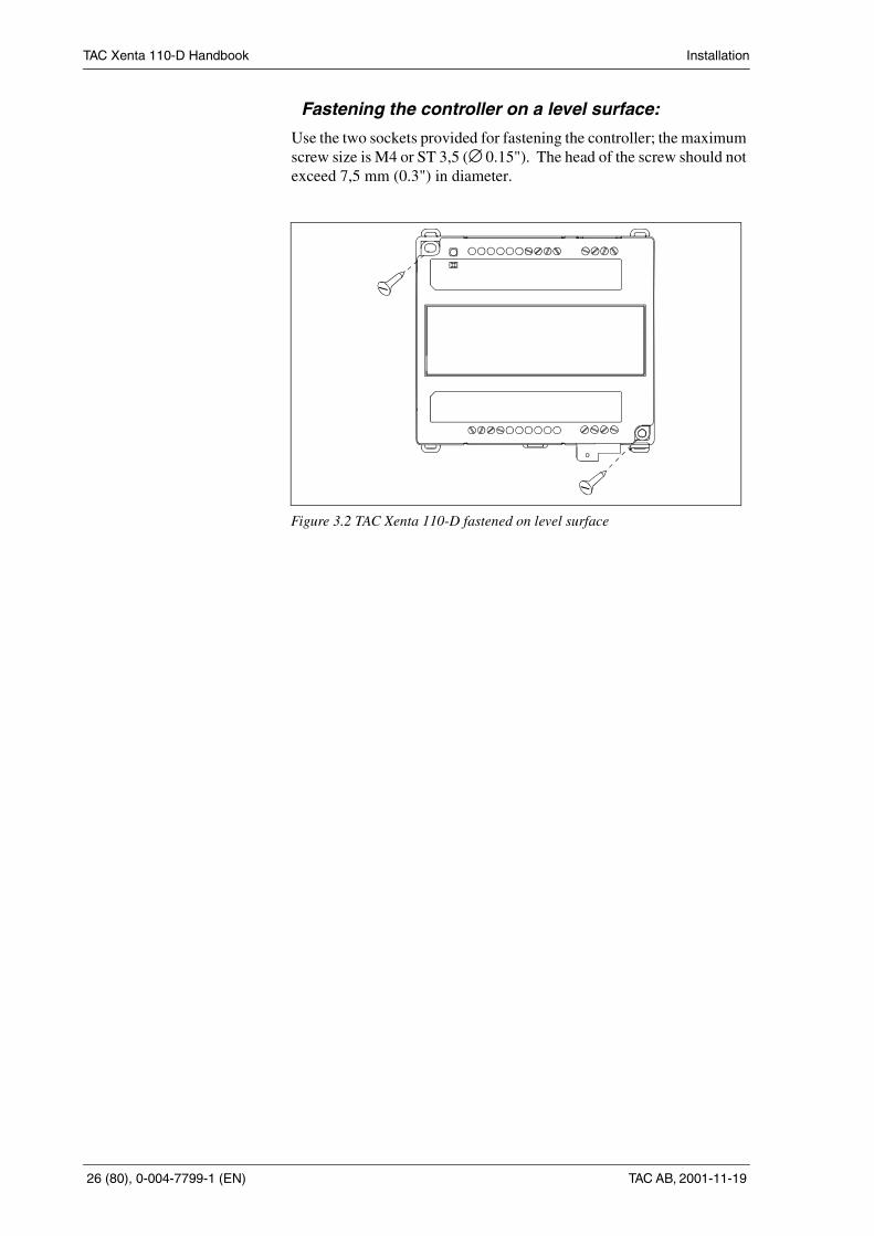
Fastening the controller on a level surface:
Use the two sockets provided for fastening the controller; the maximumscrew size is M4 or ST 3,5 (∅ 0.15"). The head of the screw should notexceed 7,5 mm (0.3") in diameter.
Figure 3.2 TAC Xenta 110-D fastened on level surface

TAC Xenta 110-D Handbook Installation
TAC AB, 2001-11-19 0-004-7799-1 (EN), 27 (80)
3.2 Electrical installation
3.2.1 General
1 Each controller or group of controllers must be fitted with max. 6 Afuses.
2 The controller is only intended for mounting inside an enclosureproviding required cable clamping and necessary protection againstelectrical shock.
3 Strap wires or shrink-to-fit tubes must be fitted to make sure thatloose 230 V (115 V) cables cannot get in contact with ELV supplycables or signal cables-and vice versa.
4 It must be simple to break the power supply for the controller or forthe complete installation.
5 TAC Xenta 110-D/24: When several TAC Xenta controllers aresupplied from a common transformer, it is important that all G’s areconnected with each other and that all G0’s are connected with eachother. They must not be interchanged.
6 TAC Xenta 110-D/24: At the transformer, G0 should be connectedto protective earth. This is to get a grounding point for interferencediversion.
7 Lamp Loads: Conventional old fluorescent lamps suffer from severepower-up current transients. The relay outputs in TAC Xenta 110-Dare only suitable for modern lamp devices equipped with HF- units.A maximum of 250W lamp loads is recommended for each outputto ensure a long relay life time.
Safety standard
Transformers supplying the controller must comply to the safety stan-dard EN 60 742 or any other relevant safety standard for ELV, 24 V AC.When equipment with a power supply of its own is connected, this po-wer supply must also comply with this norm.
Cable lengths
For information on communication cable lengths, see TAC Xenta Net-work Guide, part number 0-004-7460. For all other cables, maximumlength is 30 m (100 feet) and min. area is 0,7 mm2 (AWG-19).
The wall modules ZS 101-ZS 104
The wall modules ZS 101-ZS 104 are intended for use with theTAC Xenta 110-D.
Warning! All 230/115 V supply cables must beinstalled by authorised electricians.

TAC Xenta 110-D Handbook Installation
28 (80), 0-004-7799-1 (EN) TAC AB, 2001-11-19
Connection terminals
The designation of the connection terminals can be seen in two placeson the controller: on the edge of the printed circuit board, and on the la-bel on the front of the controller.
Termin. Design. Function Type
1*1 X2 Light switch/Occupancy sensor/Bypass Digital input
2 M Measurement neutral -
3*1 X3 Light switch/Occupancy sensor/Bypass Digital input
4 B2 Zone temperature sensor SCC#2 Thermistor input
5 Y1 Modulating light control 1-10 V output
6 M Measurement neutral -
7*1 X1 Light switch/Occupancy sensor/bypass Digital input
8*1 R1 Setpoint adjustment for SCC#1Toggle switch for CLC
10 kΩ linear potentiometer SCC#1Digital input CLC
9 M Measurement neutral -
10 B1 Zone temperature sensor SCC#1 Thermistor input
11 K4 Light control LA#4 Relay output
12 KC2 Light control LA#4 relay common -
13 G0/115/230 V Supply voltage -
14 G/115/230 V Supply voltage -
15 C1 TP/FT-10 communication channel LON
16 C2 TP/FT-10 communication channel LON
17 M Measurement neutral -
18*1 U1 Light switch / occupancy sensor / bypass/ lux sensor/ setpoint offset dial SCC#2
Digital input 0-10 V10 kΩ linear potentiometer SCC#2
19*1 V1 Heating valve SCC#1, on-off Triac output
20 G 24 V AC (L) supply for V1, V2 -
21*1 V2 Cooling valve SCC#1, on-off Triac output
22*1 V3 Heating valve SCC#2, on-off Triac output
23 G 24 V AC (L) supply for V3, V4 -
24*1 V4 Cooling valve SCC#2, on-off Triac output
25 K3 Light control LA#3 Relay output
26 K2 Light control LA#2 Relay output
27 K1 Light control LA#1 Relay output
28 KC1 Light control LA#1-3 common -
*1 See Configuration parameters

TAC Xenta 110-D Handbook Installation
TAC AB, 2001-11-19 0-004-7799-1 (EN), 29 (80)
3.2.2 Wiring of TAC Xenta 110-D/24
Note! Read section 3.2.1 "General" before you connect the cables ac-cording to the wiring diagram in figure 3.3.
Note: KC2/K4 may not be connected to mains supply since isolationclearance to G0 terminal does not meet 6.5 mm (1/4") safety require-ment.
Light control
Light sensor/switchOccupancy sensor/Temperature offset 2
X3M MM R1 B1
V1 KC1G G
1 2 3 4 5 6 7 8 9 10 11 12 13 14
15 16 17 18 19 20 21 22 23 24 25 26 27 28K1V2
TAC Xenta 110-D/24
B2
Thermal actuators
V3 V4
Ligh
tcon
trol
grou
ps
K3 K2C2C1 M U1
X2 Y1 X1 GG0KC2K4
24V
24V
1-10 V
0-10
V
Tem
p.1
Tem
p.2
Temperature offset 1
HFD Unit
TAC Xenta OPLON
230 V ACor
115 V AC
24 V AC
Ligh
tsw
itche
s/O
ccup
ancy
sesn
ors/
Byp
as
10 kΩ
Hea
ting
Hea
ting
Coo
ling
Coo
ling
!CAT III (IEC 664)
Figure 3.3 Wiring of TAC Xenta 110-D/24

TAC Xenta 110-D Handbook Installation
30 (80), 0-004-7799-1 (EN) TAC AB, 2001-11-19
3.2.3 Wiring of TAC Xenta 110-D/115
Note! Read section 3.2.1 "General" before you connect the cables ac-cording to the wiring diagram in figure 3.4.
Note: KC2 may also be connected to 24 V but must in this case be wiredaccording to mains safety rules since isolation clearance to the mainsterminal do not meet 6.5 mm (1/4") safety requirements.
X3M MM R1 B1
V1 KC1G G
1 2 3 4 5 6 7 8 9 10 11 12 13 14
15 16 17 18 19 20 21 22 23 24 25 26 27 28K1V2
TAC Xenta 110-D/115
B2
Thermal actuators
V3 V4
Ligh
tcon
trol
grou
ps
K3 K2C2C1 M U1
X2 Y1 X1 KC2K4
24V
24V
1-10 V
0-10
V
Tem
p.1
Tem
p.2
Temperature offset 1
HFD Unit
Light control
Light sensor/switchOccupancy sensorTemperature offset 2
TAC Xenta OP
LON
115 V AC
Ligh
tsw
itche
s/O
ccup
ancy
sesn
ors/
Byp
ass
115 V
10 kΩ
Figure 3.4 Wiring of TAC Xenta 110-D/115
TAC Xenta 110-D Handbook Installation
TAC AB, 2001-11-19 0-004-7799-1 (EN), 31 (80)
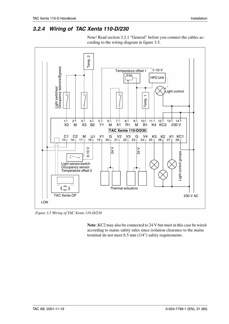
3.2.4 Wiring of TAC Xenta 110-D/230
Note! Read section 3.2.1 "General" before you connect the cables ac-cording to the wiring diagram in figure 3.5.
Note: KC2 may also be connected to 24 V but must in this case be wiredaccording to mains safety rules since isolation clearance to the mainsterminal do not meet 6.5 mm (1/4") safety requirements.
X3M MM R1 B1
V1 KC1G G
1 2 3 4 5 6 7 8 9 10 11 12 13 14
15 16 17 18 19 20 21 22 23 24 25 26 27 28K1V2
TAC Xenta 110-D/230
B2
Thermal actuators
V3 V4
Ligh
tcon
trol
grou
ps
K3 K2C2C1 M U1
X2 Y1 X1 KC2K4
24V
24V
1-10 V
0-10
V
Tem
p.1
Tem
p.2
Temperature offset 1
HFD Unit
Light control
Light sensor/switchOccupancy sensorTemperature offset 2
TAC Xenta OP
LON
230 V AC
Ligh
tsw
itche
s/O
ccup
ancy
sesn
ors/
Byp
ass
230 V
10 kΩ
Figure 3.5 Wiring of TAC Xenta 110-D/230

TAC Xenta 110-D Handbook Installation
32 (80), 0-004-7799-1 (EN) TAC AB, 2001-11-19
3.2.5 How to connect the TAC Xenta OP to the wall module
The TAC Xenta 110-D has an OP access connecter (RJ-10) mounted di-rectly on the controller. This should be used to connect the TAC XentaOP (not to the wall module as with previous TAC Xenta 100 control-lers).
If there is a need to connect the TAC Xenta OP to the wall module, it ispossible to modify the wiring and connect an RJ-10 to terminal adapter(0-073-0921-0). The same requirements apply to the LON-connectionas for the rest of the installation (see section 3.2.1). The terminalsshould be connected as:
RJ-10 to terminal adapter Signal Wall module
T2 BK 24 V AC, OP supply OP
R1 RD 24 V AC, OP supply G
T1 GR Lon (TP/FT-10) C1
R2 YL Lon (TP/FT-10) C2
R2 YL T1 GR
R1 RDT2 BK
Figure 3.6 Terminal adapter

TAC Xenta 110-D Handbook Installation
TAC AB, 2001-11-19 0-004-7799-1 (EN), 33 (80)
How to connect the adapter (with two different ways to connect to theLonWorks network) can be seen in the figures below:
Note! The cable between the controller and the adapter must not becrossed (see figures above).
Max. 1 m Max. 30 m
ZS 10X
TA
CX
enta
110-
D
LON
RJ-10 to termi-nal adapter C2 C1G OP
LON cable
Figure 3.7 TAC Xenta OP to wall module connection, alternative 1
Max. 1 m Max. 30 m
ZS 10X
TA
CX
enta
110-
D
LON
C2 C1G OP
Figure 3.8 TAC Xenta OP to wall module connection, , alternative 2
TAC Xenta 110-D Handbook Installation
34 (80), 0-004-7799-1 (EN) TAC AB, 2001-11-19
3.3 Commissioning
3.3.1 GeneralWhen the mechanical and electrical installation has been made, you cancommission the controller. This means:
• Installing the controller on the network, set node status andgive it an address.
• Set the controller’s configuration parameters.
• Bind network variables.
• Test the function.
When it comes to the commisioning of complete zone systems, read themanual "TAC Xenta - Zone Systems Guideline". Here you will find ashort description of what to do and when to do it.
When TAC Xenta 100 will be used stand-alone, this is how:
1 Set node status to "Configured" with TAC Xenta OP.
2 Set the basic parameters with TAC Xenta OP.
3 Test the function.
4 If required, fine tune other parameters and variables with TACXenta OP.
You could also use a network management tool for the commissioning.
3.3.2 Node statusThe node status indicates which mode the controller is in, when it comesto network configuration and program. The status can be changed withTAC Vista (version 3.1 or later), network management tool, or, to someextent, TAC Xenta OP. The controller can be in these states:
Unconfigured
The controller is in this state when delivered from the factory. Neitherthe program nor the network communication are running. The servicelight emitting diode is flashing.
The controller cannot work on a network in this state. To do so, it mustbe in configured, online state, see below.
You cannot set configuration parameters or network variables in thisstate.
Configured, online
By means of TAC Xenta OP, TAC Vista or a network management tool,the status can be changed to configured. Then, both the program and thenetwork communication are running. The service LED is off. This is thenormal state for a controller in operation.
Now the controller uses the address which it was given by the toolduring configuration. With TAC Xenta OP you cannot, however, set anaddress. Therefore all controllers get default addresses. This means that

TAC Xenta 110-D Handbook Installation
TAC AB, 2001-11-19 0-004-7799-1 (EN), 35 (80)
such a TAC Xenta 100 cannot work on a network. It can only workstand-alone.
In this state you can set parameters and variables.
Configured, soft offline
To get the controller into this state, you need a network managementtool. The controller has a program and a network configuration, but theprogram and the communication are at a standstill. The light emittingdiode is off. If the controller is reset, it will go into configured, online.
Configured, hard offline
To get the controller into this state, you need a network managementtool. The controller has a program and a network configuration, but theprogram and the communication are at a standstill. The light emittingdiode is off. If the controller is reset, it will remain in this state.
Without a program and not configured
This states indicates that there is something wrong with the controller.No program can be detected. The ligh emitting diode is lit.
3.3.3 Configuration parameters (nci’s)TAC Xenta 100 has a number of configuration parameters, where youcan set how the controller should be working. There are also networkvariables which controls the controller during operation. For a descrip-tion of the configuration parameters, see section 3.4.
Use the commissioning protocol in Appendix B to write down your set-tings at commissioning. In chapter 6, there is information on all parame-ters and variables, such as their index, accepted values, default values.
A plug-in for use with LonMaker for Windows is available.
3.3.4 Network installation
For network installation, you need either a network management tool(LNS based or not). The TAC prefered choice of network managementtools is LonMaker for Windows. Here you find brief information onhow this is made. You find more information in "TAC Xenta, Guideli-nes for zone applications" and "TAC Xenta and LonMaker".
The installation has two steps:
1 Feed information about the controllers’ unique neuron-ID into thenetwork management tool’s data base.
2 Let the network management tool install the controller on the net-work. The controller will then also get an address.
There are two ways to feed the neuron-ID into the data base:
1 Manually feed the neuron-ID into the network management tool. Tomake this easier you can use a bar code reader to read the detacha-ble ID-neuron label, which you find on every controller. It is suita-ble to gather these labels when you go around and make the basicconfiguration, and stick them to a form, drawing or similar. In the

TAC Xenta 110-D Handbook Installation
36 (80), 0-004-7799-1 (EN) TAC AB, 2001-11-19
manual "TAC Xenta, Guidelines for zone applications" there is aform for this purpose.
2 Use the service pin function. You can only do this when the control-ler is connected to the network. On the controller there is a servicepin key in a hole in the upper left corner, at terminal X2. When youpush this, the controller sends out its neuron-ID. The networkmanagement tool can then read the neuron-ID from the network, tosave it in its data base.
3.3.5 Network variable bindingHow binding is done depends on which network management tool isused. To get exact information, you should use the tool’s documenta-tion. In "TAC Xenta Network manual", there is a description of hownetwork variables are bound.
To bind network variables is not an issue when the controller is used instand-alone operation.
3.3.6 Network variable preservationIt is important to know that only configuration variable (nci:s) are pre-served after a power down.
Note: If not bound network variables (nvi:s) are changed by a networktool, TAC Xenta OP or LonMaker for Windows, their value will revertto default after a power up.
3.3.7 Function testYou should also make sure that the controller works as intended.
In chapter 5 all the controller’s functions are described.
In chapter 4 you find help, should a problem occur.

TAC Xenta 110-D Handbook Installation
TAC AB, 2001-11-19 0-004-7799-1 (EN), 37 (80)
3.4 Configuration parametersThe controller can be easily configured by using the configuration pa-rameters:
3.4.1 nciAppOptions
These parameters are used to set selectable functions in the controller.nciAppOptions consists of 16 bits, where each bit sets a specific func-tion (0 or 1). When you use the TAC Xenta OP to view nciAppOptions,the leftmost digit shown is bit 0. The table below shows an overview ofthe options. Default values in bold.
Index Variable Description
0 nciLocation Location label. Used to make a label for the actual place where the con-troller is mounted.
16 nciLuxSepoint Lux control setpoint. Default value 300 lux.
17 nciLuxMin Minimum lux level. Default value 0 lux.
18 nciGain Gain for lux controller. Default value 1.
19 nciItime Integral time for lux controller. Default value 60 s.
20 nciLuxPerVolt Conversion factor Lux per Volt. Default value 1000.
34 nciSetpoints1 Occupancy temperature setpoints for SCC#1. Used for setting the tempe-rature setpoints in the different operating modes: comfort, economy andunoccupied mode (see section 5.2).
35 nciBypassTime1 Time for bypass mode for SCC#1. Default value 120 minutes.
36 nciHeatPrimMin1 Minimum output for heating controller for SCC#1. Used for setting theminimum value for the operation of the heating valve. Default value 0%.
50 nciSetpoints2 Occupancy temperature setpoints for SCC#2. Used for setting the tempe-rature setpoints in the different operating modes: comfort, economy andunoccupied mode (see section 5.2).
51 nciBypassTime2 Time for bypass mode for SCC#2. Default value 120 minutes.
52 nciHeatPrimMin2 Minimum output for heating controller for SCC#2. Used for setting theminimum value for the operation of the heating valve. Default value 0%.
58 nciAppOptions See section 3.4.1.
59 nciAppOptions2 See section 3.4.2.
60 nciSndHrtBt Send heartbeat. Used for setting the intervall between sending the nvo’son the network. Default value 0.0 s (disabled).
Bit no. Function
Bit 0 0 Hard wired bypass button for SCC#1 control
1 Hard wired occupancy sensor for SCC#1 control
Bit 1 0 Hard wired bypass button for SCC#2 control

TAC Xenta 110-D Handbook Installation
38 (80), 0-004-7799-1 (EN) TAC AB, 2001-11-19
3.4.2 nciAppOptions2nciAppOptions2 also consists of 16 bits, where each bit sets a specificfunction (0 or 1). When you use the TAC Xenta OP to viewnciAppOptions2, the leftmost digit shown is bit 0. Default values inbold.
The table below shows an overview of the options:
1 Hard wired occupancy sensor for SCC#2 control
Bit 2 0 Disable X1 as bypass/occupancy input for SCC#1
1 Enable X1 as bypass/occupancy input for SCC#1
Bit 3 0 Disable X2 as bypass/occupancy input for SCC#1
1 Enable X2 as bypass/occupancy input for SCC#1
Bit 4 0 Disable X3 as bypass/occupancy input for SCC#1
1 Enable X3 as bypass/occupancy input for SCC#1
Bit 5 0 Disable U1 as bypass/occupancy input for SCC#1
1 Enable U1 as bypass/occupancy input for SCC#1
Bit 6 0 Diable X1 as bypass/occupancy input for SCC#2
1 Enable X1 as bypass/occupancy input for SCC#2
Bit 7 0 Disable X2 as bypass/occupancy input for SCC#2
1 Enable X2 as bypass/occupancy input for SCC#2
Bit 8 0 Disable X3 as bypass/occupancy input for SCC#2
1 Enable X3 as bypass/occupancy input for SCC#2
Bit 9 0 Disable U1 as bypass/occupancy input for SCC#2
1 Enable U1 as bypass/occupancy input for SCC#2
Bit 10&11 00 U1 used as digital input for toggle switch or bypass/occupancy input
01 U1 used as lux input for the CLC
10 U1 used as temperature offset input for SCC#2
Bit 12 0 Slave mode for SCC#1 disabled
1 Slave mode for SCC#1 enabled
Bit 13 0 Slave mode for SCC#2 disabled
1 Slave mode for SCC#2 enabled
Bit 14 0 Not used
Bit no. Function
Bit 0 0 Disable X1 as toggle switch for Lamp actuator #1
Bit no. Function

TAC Xenta 110-D Handbook Installation
TAC AB, 2001-11-19 0-004-7799-1 (EN), 39 (80)
1 Enable X1 as toggle switch for Lamp actuator #1
Bit 1 0 Disable X2 as toggle switch for Lamp actuator #2
1 Enable X2 as toggle switch for Lamp actuator #2
Bit 2 0 Disable X3 as toggle switch for Lamp actuator #3
1 Enable X3 as toggle switch for Lamp actuator #3
Bit 3 0 Disable U1 as toggle switch for Lamp actuator #4
1 Enable U1 as toggle switch for Lamp actuator #4
Bit 4 0 Power up status for Lamp Actuator #1 is OFF
1 Power up status for Lamp Actuator #1 is ON
Bit 5 0 Power up status for Lamp Actuator #2 is OFF
1 Power up status for Lamp Actuator #2 is ON
Bit 6 0 Power up status for Lamp Actuator #3 is OFF
1 Power up status for Lamp Actuator #3 is ON
Bit 7 0 Power up status for Lamp Actuator #4 is OFF
1 Power up status for Lamp Actuator #4 is ON
Bit 8 0 Occupancy detection resumes status of Lamp Actuator #1
1 Occupancy detection requires switch X1 action to turn Lamp Actuator #1 on
Bit 9 0 Occupancy detection resumes status of Lamp Actuator #2
1 Occupancy detection for toggle switch X2 action to turn Lamp Actuator #2 on
Bit 10 0 Occupancy detection resumes status of Lamp Actuator #3
1 Occupancy detection for toggle switch X3 action to turn Lamp Actuator #3 on
Bit 11 0 Occupancy detection resumes status of Lamp Actuator #4
1 Occupancy detection for toggle switch U1 action to turn Lamp Actuator #4 on
Bit 12 0 R1 used as input for setpoint adjustment to CLC (only when bit 15=1)
1 R1 used as input for light toggle switch to CLC (only when bit 15=1)
Bit 13 0 Thermal actuators are of NC type (Normally Closed)
1 Thermal actuators are of NO type (Normally Open)
Bit 14 0 Temperature control hysteris is 0.2 degrees
1 Temperature control hysteris is 0.8 degrees
Bit 15 0 R1 used as input for SCC#1
1 R1 used as input for CLC
Bit no. Function
TAC Xenta 110-D Handbook Installation
40 (80), 0-004-7799-1 (EN) TAC AB, 2001-11-19

TAC Xenta 110-D Handbook Operation
TAC AB, 2001-11-19 0-004-7799-1 (EN), 41 (80)
4 Operation4.1 General
TAC Xenta 110-D is normally a very reliable controller.
The controller has several alarms, explained in section 4.2.
If there are any problems, you can use the troubleshooting tips in thischapter (section 4.3), preferably when the controller is run on a network,but also when it is used stand-alone. If you need further help, pleasecontact the nearest local sales office.

TAC Xenta 110-D Handbook Operation
42 (80),0-004-7799-1 (EN) TAC AB, 2001-11-19
4.2 AlarmWhen TAC Xenta 110-D reports alarms to a monitoring system, this isdone with the network variable nvoAlarmStatus. The variable has 16bits, which corresponds to different alarm situations.
Alarm modes for nvoAlarmStatus
Bit Alarm Cuts out when... Is reset when...
0 Deviating zone temperatureSCC#1
The deviation in zone tempera-ture is more than 2 ºC (4 ºF) formore than 60 minutes (occupiedand bypass modes).
The deviation in zone tempera-ture is less than 1.5 ºC (3 ºF)(hysteresis 0.5 ºC, 0.9 ºF)
1 Deviating zone temperatureSCC#2
The deviation in zone tempera-ture is more than 2 ºC (4 ºF) formore than 60 minutes (occupiedand bypass modes).
The deviation in zone tempera-ture is less than 1.5 ºC (3 ºF)(hysteresis 0.5 ºC, 0.9 ºF)
2 Low zone temperatureSCC#1
The zone temperature is lowerthan 10 ºC (50 ºF) for more than60 minutes (standby and unocc.modes).
The zone temperature is morethan 12 ºC (54 ºF).
3 Low zone temperatureSCC#2
The zone temperature is lowerthan 10 ºC (50 ºF) for more than60 minutes (standby and unocc.modes).
The zone temperature is morethan 12 ºC (54 ºF).
4 Deviation of CLC lightlevel
The deviation of CLC level ismore than 20% of actual set-point.
The deviation of CLC level isless than 20% of actual setpoint.
10 Unbound nvi:s have notbeen received
Power on. When the first not bound net-work variable have been recei-ved.
11 Adaption of thermistor Internal writing error in the con-troller memory.
The controller must be replaced.
13 Non-valid value on input An input network variable isoutside of its accepted values.
The variable gets an acceptedvalue.
14 No application program No valid application program. The controller must be replaced.
15 (Flash) memory write error The controller is faulty. The controller must be replaced.

TAC Xenta 110-D Handbook Operation
TAC AB, 2001-11-19 0-004-7799-1 (EN), 43 (80)
4.3 Problems and solutionsA list of common problems and solutions is supplied below:
What affects... Check...
Operation? • Bypass button on wall module (X1-3, U1). If the bypass buttonhas been pressed, the time (nciBypassTime) must expire beforenormal occupancy mode returns.• Occupancy sensor (X1-3, U1) or network variable nviOccSen-sor. If the occupancy sensor indicated occupancy, there will be adelay (nciBypassTime) before switching to standby.• Order via network, nviOccManCmd.
Operation mode?(Forcing the controller)
• Chosen settings in nciAppOptions and nciAppOptions2.• Outputs heating/cooling, nvoUnitStatus, nvoTerminalLoad,nvoHeatPrimary, nvoCoolPrimary which can be affected bynormal control or nciHeatPrimMin.
Control temperature set-point?
• Current operation mode, nvoEffectOccup.• Set basic setpoints, nciSetpoints.• nviSetpntOffset and or the setpoint knob on the wall module.Both of them give an offset to the values in nciSetpoints.
Read room temperature? • Zone temperature sensor (B1-2) or network variable nviSpace-Temp. A valid value on the network overrides the temperaturesensor.
That an alarm is set? • Current operation mode, nvoEffectOccup.
The light is off whenentering a room?
• Current state of nviLampValue and occupancy mode, nviOccu-pancy.• Configuration of toggle switch in bit 0-3 in nciAppOptions2.• Configuration of power up status in bit 4-7 in nciAppOptions2.• Configuration of resume function in bit 8-11 innciAppOptions2.
Light level control? • The value of nvoLampValue.• Lux level sensor (U1) or network variable nviLuxLevel.• If the input R1 is assigned as a toggle switch, the light levelsetpoint will toggle between 10%, 100% and light control.• If the Input R1 is assigned for light SP adjustment, the effec-tive setpoint is not possible to monitor once the adjustmentswitch has been pushed the first time.• Configuration of input R1, bit 12 and 15 in nciAppOptions2.• Configuration of input U1, bit 10/11 in nciAppOptions.

TAC Xenta 110-D Handbook Operation
44 (80),0-004-7799-1 (EN) TAC AB, 2001-11-19

TAC Xenta 110-D Handbook Functionaldescription
TAC AB, 2001-11-19 0-004-7799-1 (EN), 45 (80)
5 Functional description5.1 General
The TAC Xenta 110-D introduces several new features to theTAC Xenta 100 family:
• It is possible to have space comfort control and lighting control intwo zones.
• There are several inputs with multi-purpose use, for occupancy sen-sors, bypass buttons , toggle switch and more.
The controller contains 8 LonMark objects:
• 2 Space comfort controllers, SCC (section 5.2) for basic coolingand heating (on/off) control.
• 4 light actuator objects, LA (section 5.3) for switching lamps on/offby using switches and occupancy signals.
• 1 Constant Light controller object, CLC (section 5.4) for adjustablelight level control.
• 1 node object
The flexibility of the TAC Xenta 110-D is the possibility of interactionbetween the different objects.
The node status is explained in section 5.5.
In section 5.6, More about functions, you will find a description of:occupancy sensors, minimum heat output, sun-blind control and master/slave operation.
Each section in this chapter is ended with information on which networkvariables are used in the current control situation. If you need detailsabout the network variables’ characteristics, such as default values andaccepted values, you find this in chapter 6.

TAC Xenta 110-D Handbook Functionaldescription
46 (80),0-004-7799-1 (EN) TAC AB, 2001-11-19
5.2 Space Comfort controller, SCC
The controller has two identical Space Confort controller objects. In thedescription below, all the variables are mentioned without any SCCnumber. They all have either a 1 or a 2, depending on which SCC theybelong to.
5.2.1 Occupancy modesThe two SCC objects has four selectable operation modes:
• Occupied
• Standby
• Bypass
• Unoccupied
The occupancy mode is controlled by nviOccManCmd, but is also influ-enced by occupancy sensors or the bypass button on the wall module.The connection between these are shown in table below. There you willalso find the controller’s values during stand-alone operation.
Occupied mode
In occupied mode, the controller maintains a comfortable indoor clima-te. This is the default mode after power up or reset. The controller is inthis mode when nviOccManCmd=OC_OCCUPIED (or OC_NUL aftera power down).
Desired operationnviOccManCmd Bypass timer1 Occupancy sensor2 nvoEffectOccup
OccupiedOC_OCCUPIED
Enabled Without significance OC_OCCUPIED
At a stand-still OccupiedUnoccupied
OC_OCCUPIEDOC_STANDBY
StandbyOC_STANDBY
Enabled Without significance OC_BYPASS
At a stand-still Without significance OC_STANDBY
UnoccupiedOC_UNOCCUPIED
Enabled Without significance OC_BYPASS
At a stand-still Without significance OC_UNOCCUPIED
Stand-aloneOC_NUL
Enabled OccupiedUnoccupied
OC_OCCUPIEDOC_BYPASS
At a stand-still OccupiedUnoccupied
OC_OCCUPIEDOC_STANDBY
BypassOC_BYPASS
Without signifi-cance
Without significance OC_BYPASS
1 Activated by the bypass button on the wall module2 See section 5.5.1 about occupancy sensors
TAC Xenta 110-D Handbook Functionaldescription
TAC AB, 2001-11-19 0-004-7799-1 (EN), 47 (80)
• The setpoints used are found in nciSetpoints (occupied_heat andoccupied_cool).
• Bypass function is enabled.
• Network variable nviSetpntOffset is valid.
• Setpoint offset dial is valid.
• The alarm for zone temperature deviation is enabled.
• The alarm for low zone temperature is disabled.
Standby mode
In standby mode, the controller lowers the energy consumption in thezone. The controller is in this mode when nviOccManCmd =OC_STANDBY and the bypass button has not been pressed.
• The setpoints used are found in nciSetpoints (standby_heat andstandby_cool).
• Bypass function is enabled.
• Network variable nviSetpntOffset is valid.
• Setpoint offset dial is valid.
• The alarm for zone temperature deviation is disabled.
• The alarm for low zone temperature is enabled.
Bypass mode
The bypass key on the wall module is used if you want to turn to occu-pied mode occasionally from standby or unoccupied mode. When so-meone presses the bypass button on the wall module, the bypass timeris started and the controller turns to bypass mode. The bypass timer runsfor the time specified in nciBypassTime, and after that the controllerchanges operation mode according to table above.
Bypass mode can also be set with nviOccManCmd. When nciBypassTi-me has elapsed, nviOccManCmd resumes it’s previous state.
• The setpoints used are found in nciSetpoints (occupied_heat andoccupied_cool).
• Bypass function is enabled.
• Network variable nviSetpntOffset is valid.
• Setpoint offset dial is valid.
• The alarm for zone temperature deviation is enabled.
• The alarm for low zone temperature is disabled.
Unoccupied mode
When the zone is not used for a longer period of time, the controller canbe set in unoccupied mode. The controller is in this mode when nviOcc-ManCmd=OC_UNOCCUPIED.
• The setpoints used are found in nciSetpoints (unoccupied_heat andunoccupied_cool).
• Bypass function is enabled.

TAC Xenta 110-D Handbook Functionaldescription
48 (80),0-004-7799-1 (EN) TAC AB, 2001-11-19
• Network variable nviSetpntOffset is invalid.
• Setpoint offset dial is invalid.
• The alarm for zone temperature deviation is disabled.
• The alarm for low zone temperature is enabled.
5.2.2 Zone temperature controlSCC#1 and SCC#2 have 3 dedicated physical in/outputs each:
The control principle is ON/OFF with configurable hysteresis and neu-tral zone. Some additional inputs, like bypass and occupancy signals,can be configured to different inputs.
Zone temperature measurement
The zone temperature can be measured either with a hard-wired tempe-rature sensor (usually in the wall module) or with a LonTalk temperatu-re sensor node connected to nviSpaceTemp.
The network variable nvoSpaceTemp is used to monitor the effectivezone temperature. If nviSpaceTemp has a valid value, this output willecho the value of the input. If there is no valid value for nviSpaceTemp,the value from the hard-wired sensor is used. If neither variable is avai-lable, the output will send the invalid value.
nvoSpaceTemp is sent out when it has changed more than 0,1°C.
Zone temperature setpoints
nciSetpoints defines six temperature setpoints:
• heating setpoint occupied mode
• cooling setpoint occupied mode
Index Variable name Description
21 nvoEffectOccup1 Actual occupancy output SCC#1
28 nviOccManCmd1 Occupancy scheduler input SCC#1
34 nciSetpoints1 Temperature setpoints SCC#1
35 nciBypassTime1 Bypass timer SCC#1
37 nvoEffectOccup2 Actual occupancy output SCC#2
44 nviOccManCmd2 Occupancy scheduler input SCC#2
50 nciSetpoints2 Temperature setpoints SCC#2
51 nciBypassTime2 Bypass timer SCC#2
Heating output Cooling output Space temperature input
SCC#1 V1 V2 B1
SCC#2 V3 V4 B2

TAC Xenta 110-D Handbook Functionaldescription
TAC AB, 2001-11-19 0-004-7799-1 (EN), 49 (80)
• heating setpoint standby mode
• cooling setpoint standby mode
• heating setpoint unoccupied mode
• cooling setpoint unoccupied mode
The minimum accepted deviation between the heating and cooling set-points is 0,5 °C, and the heating setpoints must be lower than the coo-ling setpoints. If the heating setpoints are higher or equal to the coolingsetpoints, the controller resets the heating setpoint to 0,5 °C lower thanthe cooling setpoint. The table below shows accepted values and defaultvalues for the six temperature setpoints in nciSetpoints.
The setpoints for occupied and standby mode are basic setpoints, whichcan be changed with nviSetPntOffset and the setpoint knob. The unoc-cupied mode setpoints are always valid.
Setpoint offset input
The network varaible nviSetpointOffset is used for adding an offset tothe current setpoint (only for occupied and standby mode).
Can be used:
• bound to a supervisory node providing outside temperature com-pensation
• bound to an external Lon-based wall module node with a relativesetpoint dial.
• Inputs R1 (SCC#1) and U1 (SCC#2) can be configured for hard-wired setpoint offset dials (e.g. wall module).
If both nviSetpointOffset and the local setpoint offset dial are used to-gether, the result on the effective setpoints is additive.
Setpoint Min. Max. Default
Cooling, occupied 10 °C 35 °C 23 °C
Heating, occupied 10 °C 35 °C 21 °C
Cooling, standby 10 °C 35 °C 25 °C
Heating, standby 10 °C 35 °C 19 °C
Cooling, unoccupied 10 °C 35 °C 28 °C
Heating, unoccupied 10 °C 35 °C 16 °C
Index Variable name Description
25 nvoSpaceTemp1 Zone temperature output SCC#1
29 nviSpaceTemp1 Zone temperature input SCC#1
30 nviSetpntOffset1 Setpoint offset input SCC#1
34 nciSetpoints1 Occupancy temperature setpoints SCC#1
TAC Xenta 110-D Handbook Functionaldescription
50 (80),0-004-7799-1 (EN) TAC AB, 2001-11-19
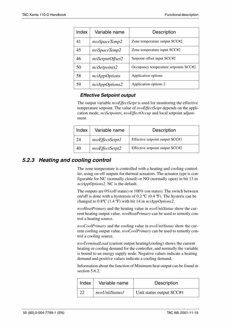
Effective Setpoint output
The output variable nvoEffectSetpt is used for monitoring the effectivetemperature setpoint. The value of nvoEffectSetpt depends on the appli-cation mode, nciSetpoints, nvoEffectOccup and local setpoint adjust-ment.
5.2.3 Heating and cooling controlThe zone temperature is controlled with a heating and cooling control-ler, using on-off outputs for thermal actuators. The actuator type is con-figurable for NC (normally closed) or NO (normally open) in bit 13 innciAppOptions2. NC is the default.
The outputs are 0%(off status) or 100% (on status). The switch betweenon/off is done with a hysteresis of 0.2 ºC (0.4 ºF). The hysteris can bechanged to 0.8ºC (1.4 ºF) with bit 14 in nciAppOptions2.
nvoHeatPrimary and the heating value in nvoUnitStatus show the cur-rent heating output value. nvoHeatPrimary can be used to remotly con-trol a heating source.
nvoCoolPrimary and the cooling value in nvoUnitStatus show the cur-rent cooling output value. nvoCoolPrimary can be used to remotly con-trol a cooling source.
nvoTerminalLoad (current output heating/cooling) shows the currentheating or cooling demand for the controller, and normally the variableis bound to an energy supply node. Negative values indicate a heatingdemand and positive values indicate a cooling demand.
Information about the function of Minimum heat output can be found insection 5.6.2.
41 nvoSpaceTemp2 Zone temperature output SCC#2
45 nviSpaceTemp2 Zone temperature input SCC#2
46 nviSetpntOffset2 Setpoint offset input SCC#2
50 nciSetpoints2 Occupancy temperature setpoints SCC#2
58 nciAppOptions Application options
59 nciAppOptions2 Application options 2
Index Variable name Description
24 nvoEffectSetpt1 Effective setpoint output SCC#1
40 nvoEffectSetpt2 Effective setpoint output SCC#2
Index Variable name Description
22 nvoUnitStatus1 Unit status output SCC#1
Index Variable name Description

TAC Xenta 110-D Handbook Functionaldescription
TAC AB, 2001-11-19 0-004-7799-1 (EN), 51 (80)
23 nvoTerminalLoad1 Heating/cooling demand outputSCC#1
26 nvoHeatPrimary1 Heating control output SCC#1
27 nvoCoolPrimary1 Cooling control output SCC#1
38 nvoUnitStatus2 Unit status output SCC#2
39 nvoTerminalLoad2 Heating/cooling demand outputSCC#2
42 nvoHeatPrimary2 Heating control output SCC#2
43 nvoCoolPrimary2 Cooling control output SCC#2
59 nciAppOptions2 Application options 2
Index Variable name Description

TAC Xenta 110-D Handbook Functionaldescription
52 (80),0-004-7799-1 (EN) TAC AB, 2001-11-19
5.3 Lamp actuators, LAThe controller has four identical Lamp Actuator objects. In the descrip-tion below, all the variables are mentioned without any LA number.They all have either 1, 2, 3 or 4, depending on which LA they belong to.
The controller can control up to four lamp relays at the same time byLamp Actuator objects, LA#1-LA#4. The are linked to relay outputsK1-K4 respectively.
nviLampValue is affected by network changes but also by the toggleswitch inputs configured in nciAppOptons2 for the object. The statechanges on the negative flank, and will take 250 ms at most. The net-work variable nvoLampValueFb:state always reflects the current relaystatus according to nviLampValue:state and nviOccupancy (see tablebelow).
To achieve increased lamp load capacity, LA objects can be bound to-gether, in paralell or in chains, and still be controlled by a single toggleswitch, configured for the first object in the chain.
To share an occupancy sensor between climate and light control, a bin-ding between nvoEffectOccup on one of the SCCs and nviOccupancy onone or more LA can be done.
There are two different ways of occupancy detection. The choice offunction is made in bit 8-11 in nciAppOptions2. At power up, the lampstatus will reflect the settings in nciAppOptions2.
When reentering a zone with an occupancy sensor, there are two modesto choose from:
1 the light is switched on using the toggle switch
2 the same state (on/off) is resumed as when the zone was last occu-pied.
nviLampValue nviOccupancy nvoLampValueFb
Off Occupied Off
Off Bypass Off
Off Standby Off
Off Unoccupied Off
Off Invalid (default) Off
On Occupied On
On Bypass On
On Standby Off
On Unoccupied Off
On Invalid (default) On
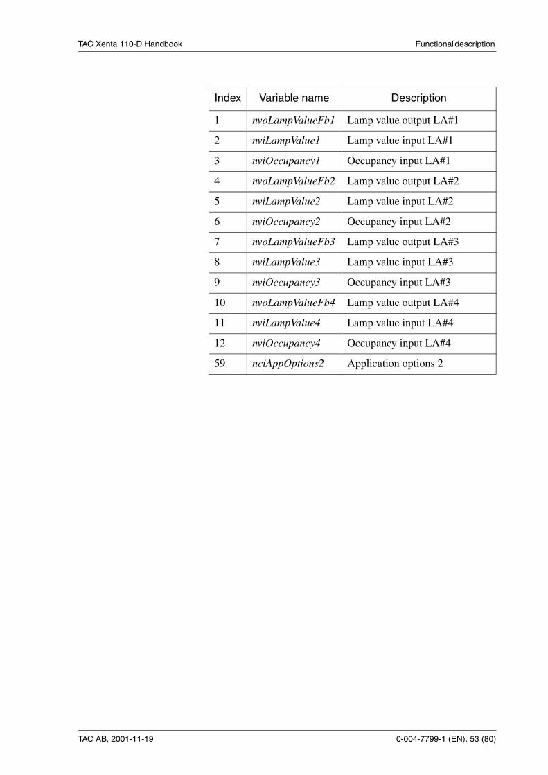
TAC Xenta 110-D Handbook Functionaldescription
TAC AB, 2001-11-19 0-004-7799-1 (EN), 53 (80)
Index Variable name Description
1 nvoLampValueFb1 Lamp value output LA#1
2 nviLampValue1 Lamp value input LA#1
3 nviOccupancy1 Occupancy input LA#1
4 nvoLampValueFb2 Lamp value output LA#2
5 nviLampValue2 Lamp value input LA#2
6 nviOccupancy2 Occupancy input LA#2
7 nvoLampValueFb3 Lamp value output LA#3
8 nviLampValue3 Lamp value input LA#3
9 nviOccupancy3 Occupancy input LA#3
10 nvoLampValueFb4 Lamp value output LA#4
11 nviLampValue4 Lamp value input LA#4
12 nviOccupancy4 Occupancy input LA#4
59 nciAppOptions2 Application options 2

TAC Xenta 110-D Handbook Functionaldescription
54 (80),0-004-7799-1 (EN) TAC AB, 2001-11-19
5.4 Constant light control, CLCThe controller has one constant light control object, CLC.
By using a lux sensor (hardwired or networked) the controller can con-trol an external HFD-unit. The Constant Light object can be configuredin several ways:
• All functions controlled via network. Usually with a LON-basedpanel (see section 2.4).
• Light level setpoint temporarily changed (up/down) by a one-poleswitch on R1.
• Light level toggled between 10%, 100% and SP-control by a one-pole switch on R1.
Configuration is made in nciAppOptions bit 10 & 11:
and in nciAppOptions2 in bit 12 and 15:
The output Y1 will deliver the constant light level, 1-10V (10-100%).nvoLampValue will echo the output (10-100%). An external HFD-devi-ce connected to a light group executes the light control.
The light feedback is fetched from nviLuxLevel (if nciAppOptions bit11=0) or the physical input U1 (if nciAppOptions bit 10=0 and 11=1).
The real light value can be monitored in nviLuxLevel when a hard-wiredsensor is connected to U1. No dedicated output variable has been assig-ned so binding the light value is not possible.
The effective setpoint used by the controller is a combination of nciLux-Setpoint and nviSetting. When nviSetting = SET_UP or SET_DOWN,every NV- update results in an increment or decrement on the Y1 outputand nvoLampValue by 2%. 10 sec. after last NV- update, the real lightvalue (from nviLuxLevel or U1) is fetched and used as a new temporarylight level setpoint.
Bit 10 Bit 11 Input U1 used as:
0 0 Digital input for toggle switch or bypass/occupancy
0 1 Lux input for the CLC object
1 0 Temperature offset input for SCC#2
Bit 12 Input R1 used as:
0 Setpoint adjustment to CLC
1 Light toggle switch to CLC
Bit 15 Input R1 used as:
0 Input to SCC#1
1 Input to CLC

TAC Xenta 110-D Handbook Functionaldescription
TAC AB, 2001-11-19 0-004-7799-1 (EN), 55 (80)
When nviSetting receives SET_OFF, the light controller is disabled andthe Y1 output and nvoLampValue (value) preserves their present status(nvoLampValue (state)=0). This gives the possibility to freeze a desiredlight output value without any control function active. When nviSettingagain receives SET_ON, the light controller is enabled and starts to con-trol against nciLuxSetpoint until a new temporary change order is recei-ved (nvoLampValue (state)=1).
The output nvoLampValue from the CLC- object can be bound to thecorresponding input on one of the lamp actuator objects for power On/Off (relay K1-K4) to the light level controlled lamp group.
In this way a LON- rotary switch can be used to toggle the lamp on/off(by pushing the rotary switch) and to adjust the lamp to a desired lightlevel (by turning the rotary switch). In a similar way a LON- four-buttonswitch (up, down, on, off) can be used for the same purpose.
When nviSetting receives SET_STATE, the real light value (from nvi-LuxLevel or U1) is fetched and copied to nciLuxSetpoint as a new de-fault setpoint for the light level.
nciGain and nciItime are configuration variables for fine tuning the lightlevel control function.
If R1 has been assigned as light setpoint adjustment input (nciAppOp-tions2 bit 12 and 15), a wall-mounted switch gives the possibility totemporarily offset the light setpoint up/down from the lux setpoint. Hol-ding the switch starts ramping the setpoint up/down (appr. 10%/sec) un-til the switch is released. The next the switch is used, it will do the same,but in the opposite direction.
If R1 is assigned as a toggle light switch input, the light level will togglebetween 0%, 100% and light setpoint for each negative signal transition.
An alarm bit, in nvoAlarmStatus, will be set when the deviation betweeneffective setpoint and the real value is more than 20%.
The calculated real value from Lux input U1 equals the voltage level (0-10 V) times the constant in nviLuxPerVolt.
Index Variable name Description
13 nvoLampValue Lamp value output CLC
14 nviLuxLevel Lux level input CLC
15 nviSetting Settings for CLC
16 nciLuxSetpoint Basic lux setpoint for CLC
17 nciLuxMin Minimum allowed lux level
18 nciGain Gain for CLC
19 nciItime Integral time for CLC
20 nciLuxPerVolt Conversion factor Lux per volt
57 nvoAlarmStatus Alarm status output
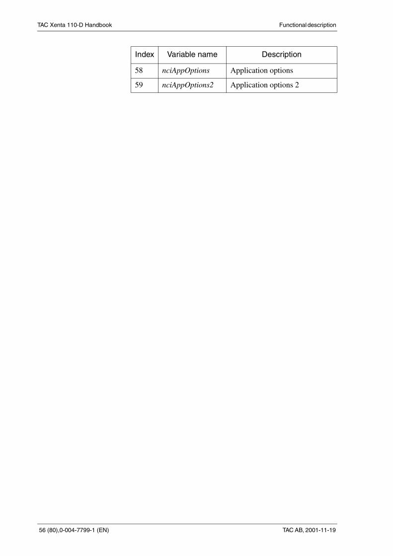
TAC Xenta 110-D Handbook Functionaldescription
56 (80),0-004-7799-1 (EN) TAC AB, 2001-11-19
58 nciAppOptions Application options
59 nciAppOptions2 Application options 2
Index Variable name Description

TAC Xenta 110-D Handbook Functionaldescription
TAC AB, 2001-11-19 0-004-7799-1 (EN), 57 (80)
5.5 More about functions
5.5.1 Occupancy sensorThe TAC Xenta 110-D has four digital inputs configurable for use withoccupancy sensors, input X1, X2, X3 and U1. The configuration aredone with nciAppOptions:
Bit 10/11 in nciAppOptions configures the use of input U1:
There can be a sensor connected to TAC Xenta 110-D, to each SCC, todetermine whether someone is in the room or not. If there is no occu-pancy sensor connected, the controller supposes that there is always so-meone in the room. The controller uses the information to determine theoperation mode. When the controller is used stand-alone, the sensor isused to choose between occupied mode or standby mode. See table inchapter 5.2.1.
All the digital inputs (X1, X2, X3 and U1) are fast scanned, with a 250ms interval.
If the input is configured for use with an occupancy sensor, the value innciBypassTime determines the delay before mode change when occu-pancy is no longer detected.
If the input is configured for use with a bypass button the detection isused for starting the bypass timer. Then the controller will be in occu-pied mode, for the time set in nciBypassTime.
Bit 0 1
0 Hard wired bypass button for SCC#1 Hard wired occupancy sensor for SCC#1
1 Hard wired bypass button for SCC#2 Hard wired occupancy sensor for SCC#2
2 Disable X1 as bypass/occupancy input for SCC#1 Ensable X1 as bypass/occupancy input for SCC#1
3 Disable X2 as bypass/occupancy input for SCC#1 Ensable X2 as bypass/occupancy input for SCC#1
4 Disable X3 as bypass/occupancy input for SCC#1 Ensable X3 as bypass/occupancy input for SCC#1
5 Disable U1 as bypass/occupancy input for SCC#1 Ensable U1 as bypass/occupancy input for SCC#1
6 Disable X1 as bypass/occupancy input for SCC#2 Ensable X1 as bypass/occupancy input for SCC#2
7 Disable X2 as bypass/occupancy input for SCC#2 Ensable X2 as bypass/occupancy input for SCC#2
8 Disable X3 as bypass/occupancy input for SCC#2 Ensable X3 as bypass/occupancy input for SCC#2
9 Disable U1 as bypass/occupancy input for SCC#2 Ensable U1 as bypass/occupancy input for SCC#2
Bit 10 Bit 11 Input U1 used as:
0 0 Digital input for toggle switch or bypass/occupancy
0 1 Lux input for the CLC object
1 0 Temperature offset input for SCC#2
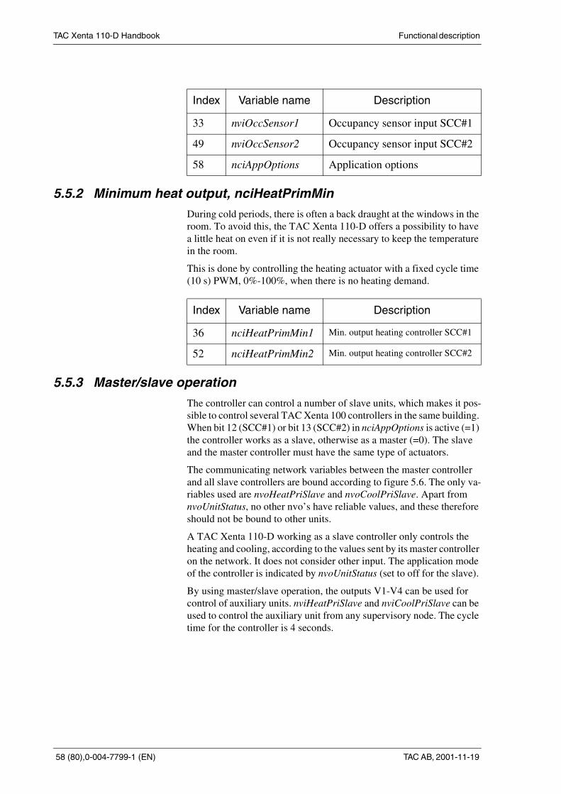
TAC Xenta 110-D Handbook Functionaldescription
58 (80),0-004-7799-1 (EN) TAC AB, 2001-11-19
5.5.2 Minimum heat output, nciHeatPrimMinDuring cold periods, there is often a back draught at the windows in theroom. To avoid this, the TAC Xenta 110-D offers a possibility to havea little heat on even if it is not really necessary to keep the temperaturein the room.
This is done by controlling the heating actuator with a fixed cycle time(10 s) PWM, 0%-100%, when there is no heating demand.
5.5.3 Master/slave operation
The controller can control a number of slave units, which makes it pos-sible to control several TAC Xenta 100 controllers in the same building.When bit 12 (SCC#1) or bit 13 (SCC#2) in nciAppOptions is active (=1)the controller works as a slave, otherwise as a master (=0). The slaveand the master controller must have the same type of actuators.
The communicating network variables between the master controllerand all slave controllers are bound according to figure 5.6. The only va-riables used are nvoHeatPriSlave and nvoCoolPriSlave. Apart fromnvoUnitStatus, no other nvo’s have reliable values, and these thereforeshould not be bound to other units.
A TAC Xenta 110-D working as a slave controller only controls theheating and cooling, according to the values sent by its master controlleron the network. It does not consider other input. The application modeof the controller is indicated by nvoUnitStatus (set to off for the slave).
By using master/slave operation, the outputs V1-V4 can be used forcontrol of auxiliary units. nviHeatPriSlave and nviCoolPriSlave can beused to control the auxiliary unit from any supervisory node. The cycletime for the controller is 4 seconds.
Index Variable name Description
33 nviOccSensor1 Occupancy sensor input SCC#1
49 nviOccSensor2 Occupancy sensor input SCC#2
58 nciAppOptions Application options
Index Variable name Description
36 nciHeatPrimMin1 Min. output heating controller SCC#1
52 nciHeatPrimMin2 Min. output heating controller SCC#2
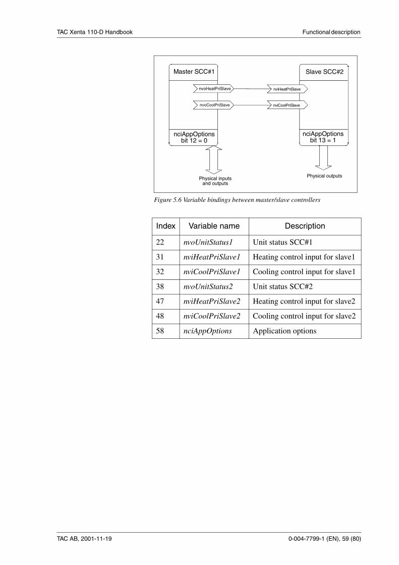
TAC Xenta 110-D Handbook Functionaldescription
TAC AB, 2001-11-19 0-004-7799-1 (EN), 59 (80)
Index Variable name Description
22 nvoUnitStatus1 Unit status SCC#1
31 nviHeatPriSlave1 Heating control input for slave1
32 nviCoolPriSlave1 Cooling control input for slave1
38 nvoUnitStatus2 Unit status SCC#2
47 nviHeatPriSlave2 Heating control input for slave2
48 nviCoolPriSlave2 Cooling control input for slave2
58 nciAppOptions Application options
Master SCC#1
nciAppOptionsbit 12 = 0
nvoCoolPriSlave
nvoHeatPriSlave nviHeatPriSlave
nviCoolPriSlave
nciAppOptionsbit 13 = 1
Slave SCC#2
Physical inputsand outputs
Physical outputs
Figure 5.6 Variable bindings between master/slave controllers

TAC Xenta 110-D Handbook Functionaldescription
60 (80),0-004-7799-1 (EN) TAC AB, 2001-11-19

TAC Xenta 110-D Handbook Communication
TAC AB, 2001-11-19 0-004-7799-1 (EN), 61 (80)
6 Communication6.1 General
The controller consists of 8 LonMark objects: the node object (section6.5), 4 lamp actuator objects (section 6.6), one constant light controllerobject (section 6.7) and 2 space comfort controller objects (section 6.8).These objects are monitored by using the network variables nviRequest(object request) and nvoStatus (object status).
The network variable nciLocation (location label) is used when confi-guring the basic parameters (chapter 3) to give a detailed description ofthe actual place of the controller. The variable receives an arbitrarystring of characters and dividers as long as the string is not longer than30 characters. You can program a certain location label, i. e.
A LNS based network management tool uses nciLocation when a data-base is recreated. The monitoring of an already installed network ismade by the LNS tool reading nciLocation, and using the informationto give the node a subsystem name and a unit name. The string shouldconsist of a name and a search path for the subsystem, followed by aslash and the unit name, i.e.
TAMF.main.floor3.room343/RC40
system.subsystem[.subsystem...]/unitname
TAC Xenta 110-D Handbook Communication
62 (80),0-004-7799-1 (EN) TAC AB, 2001-11-19
6.2 Default settings and power onThe default settings are:
• nvo:s are all unacknowledged
• nvi:s and nci:s are all acknowledged.
All network variables have the same index as in the operator panel TACXenta OP. They represent the order by which they are declared in thesystem program. The order is important for the self documentatorystring of each variable. The variables are of type SNVT (Standard Net-work Variable Types) and the values each SNVT can receive are listedin tables in the latter part of this chapter (see section 6.5-6.8).
There are also two types of parameters: SCPT (Standard ConfigurationProperty Types) and UCPT (User Configuration Property Types). If youwant more information about SNVT/SCPT/UCPT and their functions,look for “The SNVT Master List and Programmer’s Guide” available atwww.lonmark.org.
6.3 Updating network variables, HeartbeatThe TAC Xenta 110-D has a function, called Heartbeat, which can beconfigured to frequently update the output variables on the network.
The values of the bound outputs are usually sent when they change.
If a network variable is sent on heartbeat, it is shown in tables in the lat-ter part of this chapter under the heading Hb (see section 6.5-6.8).
The update intervals are set in nciSndHrtBt. The default value is 0.0, nofrequent update is performed.
6.4 Not accepted valuesAll nvo’s are limited to their accepted values, and all nvi’s detectwhether the incoming value is within the accepted limits. If the value isnot accepted, the controller activates bit 13 in nvoAlarmStatus. For annvi, the controller resume the default value, which is included as an ac-cepted value.

TAC Xenta 110-D Handbook Communication
TAC AB, 2001-11-19 0-004-7799-1 (EN), 63 (80)
6.5 The node objectThe variables in the node object (figure 6.1) are separated into three ca-tegories:
• Mandatory (M)
• Optional (O)
• Configuration properties (C)
The category “Mandatory” contains mandatory variables (according toLonMark profile for node objects), “Optional” are also described in thesame profile and “Configuration properties” contains the nci’s.
Note! The network variables’ indexes are not the same as “nv” in thefigure below.
6.5.1 The node object’s inputs (nvi)
Variable Hb1 SNVT Accepted values Default value Description
53 nviRequest No SNVT_obj_request
0=RQ_NORMAL2=RQ_UPDATE_STATUS5=RQ_REPORT_MASK
RQ_NUL(Confirmed)
Objectrequest
55 nviFileReq No SNVT_file_req see “SNVT Master List” FR_NUL(Confirmed)
File request
nv1 nv2
nv6
nviRequestSNVT_obj_request
nvoStatusSNVT_obj_status
nvoFileStatSNVT_file_status
MandatoryNetworkVariables
OptionalNetworkVariables
Node ObjectObject Type: 0
nv5 nviFileReqSNVT_file_req
Configuration PropertiesnciAppOptions SNVT_statenciAppOptions2 SNVT_statenciSendHrtBt SNVT_time_secnciLocation SNVT_location
nv1nvoAlarmStatusSNVT_state
Figure 6.1 The node object
1 Heartbeat

TAC Xenta 110-D Handbook Communication
64 (80),0-004-7799-1 (EN) TAC AB, 2001-11-19
6.5.2 The node object’s outputs (nvo)
6.5.3 The node object’s configuration parameters (nci)
Variable Hb1 SNVT Accepted values Default value Description
54 nvoStatus No SNVT_obj_status invalid_id (0..1)invalid_request (0..1)
All=0(Confirmed)
Object status
56 nvoFileStat No SNVT_file_status see “SNVT Master List” FS_NUL(Confirmed)
File status
57 nvoAlarm-Status
No SNVT_state 16 bits, 0=normal,1=alarm
0000000000000000
Alarm statusoutput
Variable SNVT Accepted valuesDefaultvalue
Description
0 nciLocation SNVT_str_ascSCPT_location (17)
30 ASCII characters All nul Location label
58 nciAppOptions SNVT_stateUCPT (1)
16 bits, 0-1 0000000000100000
Applicationoptions
59 nciAppOptions2 SNVT_stateUCPT (62)
16 bits, 0-1 1111111111110000
Applicationoptions2
60 nciSndHrtBt SNVT_time_secSCPT_maxSendTime(49)
5.0 s to 6553.4 s0.0 s = disabled
0.0 s(disabled)
Send heartbeat
1 Heartbeat

TAC Xenta 110-D Handbook Communication
TAC AB, 2001-11-19 0-004-7799-1 (EN), 65 (80)
6.6 Lamp actuator objectThe variables in the 4 lamp actuator objects (figure 6.2) are separatedinto two categories:
• Mandatory (M)
• Manufacture defined
The category “Mandatory” contains mandatory variables (according toLonMark profile for Lamp Actuator Objects), Note! The network vari-ables’ indexes are not the same as “nv” in the figure below.
6.6.1 The lamp actuator object’s inputs (nvi)
6.6.2 The lamp actuator object’s outputs (nvo)
Variable Hb1 SNVT Accepted valuesDefaultvalue
Description
25811
nviLampValue1nviLampValue2nviLampValue3nviLampValue4
No SNVT_switch state: 0=Off, 1=On,255=invalidvalue: 0-100%
state:Onvalue: 0%
Lamp command
369,12
nviOccupancy1nviOccupancy2nviOccupancy3nviOccupancy4
No SNVT_occupancy OC_OCCUPIEDOC_UNOCCUPIEDOC_BYPASSOC_STANDBYOC_NUL
OC_NUL Occupancyscheduler input
Variable Hb1 SNVT Accepted values Default value Description
14710
nvoLampValueFb1nvoLampValueFb2nvoLampValueFb3nvoLampValueFb4
No SNVT_switch state: 0=Off, 1=Onvalue: 0-100%
- Lamp status
nv1 nv2nviLampValueSNVT_switch
nvoLampValueFbSNVT_switch
MandatoryNetworkVariables
Manufacturedefined
Lamp Actuator ObjectObject Type: #3040
nv1 nviOccupancySNVT_occupancy
Figure 6.2 Lamp actuator object
1 Heartbeat
1 Heartbeat

TAC Xenta 110-D Handbook Communication
66 (80),0-004-7799-1 (EN) TAC AB, 2001-11-19
6.7 The constant light controller objectThe variables in the constant light controller object (figure 6.3) are se-parated into two categories:
• Mandatory (M)
• Configuration properties (C)
The category “Mandatory” contains mandatory variables (according toLonMark profile for CLC Objects), and “Configuration properties”contains the nci’s.
Note! The network variables’ indexes are not the same as “nv” in thefigure below.
6.7.1 The constant light controller object’s inputs (nvi)
Variable Hb1 SNVTAccepted
valuesDefault value Description
14 nviLuxLevel No SNVT_lux value: 0-65534655352
655352 Lux level input
15 nviSetting No SNVT_setting0=SET_ON1=SET_OFF2=SET_DOWN3=SET_UP4=SET_STATE
SET_OFF Lamp control settings:Controller onController offDecrement setpointIncrement setpointCopy real value to nci-LuxSetpoint
nv1 nv3nviLuxLevelSNVT_lux
nvoLampValueSNVT_switch
MandatoryNetworkVariables
Constant Light Controller ObjectObject Type: #3050
Configuration Properties
nv2 nviSettingSNVT_setting
nciLuxSetpoint SNVT_luxnciLuxPerVolt SNVT_luxnciLuxMin SNVT_luxnciGain SNVT_multipliernciItime SNVT_time_sec
Figure 6.3 The constant light controllerobject
1 Heartbeat2 Invalid value

TAC Xenta 110-D Handbook Communication
TAC AB, 2001-11-19 0-004-7799-1 (EN), 67 (80)
6.7.2 The constant light controller object’s outputs (nvo)
6.7.3 The constant light controller object’s configuration parame-ters (nci)
Variable Hb1 SNVT Accepted values Default value Description
13 nvoLampValue No SNVT_switch state: 0=Off, 1=On,value: 0-100%
Off 0% Lamp statusoutput
Variable SNVT Accepted valuesDefaultvalue
Description
16 nciLuxSetpoint SNVT_lux value: 0-65535 300 Lux control setpoint
17 nciLuxMin SNVT_lux value: 0-65535 0 Minimum lux level
18 nciGain SNVT_multiplier 0 to 32.7675 1 Gain for lux controller
19 nciItime SNVT_time_sec 0 to 3600 s0.0 s = disabled
60 s(1 minute)
Integral time for lux controller
20 nciLuxPerVolt SNVT_lux 0-5000 1000 Lux per volt
1 Heartbeat

TAC Xenta 110-D Handbook Communication
68 (80),0-004-7799-1 (EN) TAC AB, 2001-11-19
6.8 The space comfort controller objectThe variables in the two space comfort controller objects (figure 6.4) areseparated into four categories: Mandatory (M), Optional (O), Manufac-turer Defined Section (MDS) andf Configuration properties (C)
The category “Mandatory” contains mandatory variables (according toLonMark profile for Space Comfort Controller objectss), “Optional”are also described in the same profile. The “Manufacturer Defined Sec-tion” are variables used in the controller (not in the profile). “Configu-ration properties” contains the nci’s.
Note! The indexes of the network variables are not the same as “nv” inthe figure below.
nv1
nv6
nv7
nv55
nviSpaceTempSNVT_temp_p
nviOccManCmdSNVT_occupancy
nviOccSensorSNVT_occupancy
nviHeatPriSlaveSNVT_lev_percent
nciSetpoints SNVT_temp_setptnciBypassTime SNVT_time_min
Configuration Properties
Manufacturer Defined Section
MandatoryNetworkVariables
OptionalNetworkVariables
Space Comfort Controller ObjectObject Type: 8506
nv57 nviCoolPriSlaveSNVT_lev_percent
nv26 nvoSpaceTempSNVT_temp_p
nv38nvoHeatPrimarySNVT_lev_percent
nv40 nvoCoolPrimarySNVT_lev_percent
nv27 nvoUnitStatusSNVT_hvac_status
nv28 nvoEffectSetptSNVT_temp_p
nv3 nviSetpntOffsetSNVT_temp_p
nv29 nvoEffectOccupSNVT_occupancy
nv37 nvoTerminalLoadSNVT_lev_percent
nciHeatPrimMin SNVT_lev_percent
Figure 6.4 The space comfort controller
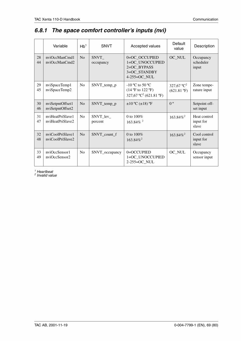
TAC Xenta 110-D Handbook Communication
TAC AB, 2001-11-19 0-004-7799-1 (EN), 69 (80)
6.8.1 The space comfort controller’s inputs (nvi)
Variable Hb1 SNVT Accepted valuesDefaultvalue
Description
2844
nviOccManCmd1nviOccManCmd2
No SNVT_occupancy
0=OC_OCCUPIED1=OC_UNOCCUPIED2=OC_BYPASS3=OC_STANDBY4-255=OC_NUL
OC_NUL Occupancyschedulerinput
2945
nviSpaceTemp1nviSpaceTemp2
No SNVT_temp_p -10 ºC to 50 ºC(14 ºF to 122 ºF)327,67 ºC2 (621.81 ºF)
327,67 ºC2
(621.81 ºF)Zone tempe-rature input
3046
nviSetpntOffset1nviSetpntOffset2
No SNVT_temp_p ±10 ºC (±18) ºF 0 º Setpoint off-set input
3147
nviHeatPriSlave1nviHeatPriSlave2
No SNVT_lev_percent
0 to 100%163.84% 2
163.84%2 Heat controlinput forslave
3248
nviCoolPriSlave1nviCoolPriSlave2
No SNVT_count_f 0 to 100%163.84%2
163.84%2 Cool controlinput forslave
3349
nviOccSensor1nviOccSensor2
No SNVT_occupancy 0=OCCUPIED1=OC_UNOCCUPIED2-255=OC_NUL
OC_NUL Occupancysensor input
1 Heartbeat2 Invalid value

TAC Xenta 110-D Handbook Communication
70 (80),0-004-7799-1 (EN) TAC AB, 2001-11-19
6.8.2 The space comfort controller’s outputs (nvo)
Variable Hb1 SNVT Accepted valuesDefaultvalue
Description
2137
nvoEffectOccup1nvoEffectOccup2
Yes SNVT_occupancy 0=OCCUPIED1=OC_UNOCCUPIED2=OC_BYPASS3=OC_STANDBY
OC_OC-CUPIED
Effectiveoccupancyoutput
2238
nvoUnitStatus1nvoUnitStatus2
Yes SNVT_hvac_statusmode
heat_output_primaryheat_output_secondarycool_output
1=HVAC_HEAT3=HVAC_COOL6=HVAC_OFF0% to 100%163.84%2
0% to 100%163.84%2
0% to 100%163.84%2
HVAC_-HEAT
163.83%2
163.83%2
163.83%2
Unit statusoutput
2339
nvoTerminalLoad1nvoTerminalLoad2
Yes SNVT_lev_percent
-163.84% to 163.83% 0% Terninal loadoutput
2440
nvoEffectSetpt1nvoEffectSetpt2
Yes SNVT_temp_p 10 ºC to 35 ºC(50 ºF to 95 ºF)327,67 ºC2
327,67 ºC2 Effective set-point output
2541
nvoSpaceTemp1nvoSpaceTemp2
Yes SNVT_temp_p -10 ºC to 50 ºC(14 ºF to 122 ºF)327,67 º2C
327,67 ºC2 Zone tempe-rature output
2642
nvoHeatPrimary1nvoHeatPrimary2
Yes SNVT_lev_percent
0% to 100%163.84%2
0 Heating con-trol outputfor slave
2743
nvoCoolPrimary1nvoCoolPrimary2
Yes SNVT_lev_percent
0% to 100%163.84%2
0 Cooling con-trol outputfor slave
1 Heartbeat2 Invalid value
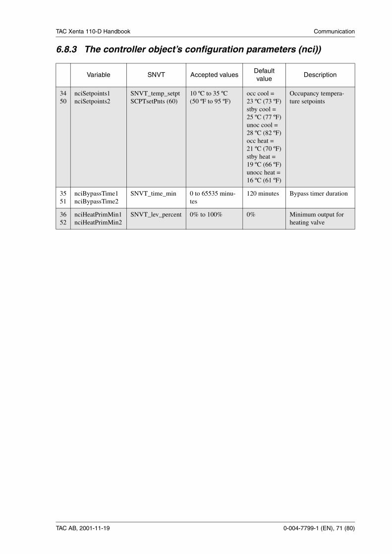
TAC Xenta 110-D Handbook Communication
TAC AB, 2001-11-19 0-004-7799-1 (EN), 71 (80)
6.8.3 The controller object’s configuration parameters (nci))
Variable SNVT Accepted valuesDefaultvalue
Description
3450
nciSetpoints1nciSetpoints2
SNVT_temp_setptSCPTsetPnts (60)
10 ºC to 35 ºC(50 ºF to 95 ºF)
occ cool =23 ºC (73 ºF)stby cool =25 ºC (77 ºF)unoc cool =28 ºC (82 ºF)occ heat =21 ºC (70 ºF)stby heat =19 ºC (66 ºF)unocc heat =16 ºC (61 ºF)
Occupancy tempera-ture setpoints
3551
nciBypassTime1nciBypassTime2
SNVT_time_min 0 to 65535 minu-tes
120 minutes Bypass timer duration
3652
nciHeatPrimMin1nciHeatPrimMin2
SNVT_lev_percent 0% to 100% 0% Minimum output forheating valve

TAC Xenta 110-D Handbook Communication
72 (80),0-004-7799-1 (EN) TAC AB, 2001-11-19

TAC Xenta 110-D Handbook Appendix A: Technical data
TAC AB, 2001-11-19 0-004-7799-1 (EN), 73 (80)
Appendix A: Technical dataSupply voltage:
110-D/24 ......................................24 V AC –20% +20%, 50–60 Hz110-D/115 ........................................115 V AC –10% +10%, 60 Hz110-D/230 ..................................230 V AC –10% +10%, 50–60 Hz
Power consumption 110-D/24:Controller with TAC Xenta OP.................................................4 VADigital outputs.............................................max. 4×19 VA = 76 VATotal ...............................................................................max. 80 VA
Power consumption 110-D/115 or 110-D/230:Controller with TAC Xenta OP.................................................5 VADigital outputs, individual outputs and total ..................max. 12 VATotal (including transformer losses) ..............................max. 20 VA
Ambient temperature:Operation........................................ 0 °C – +50 °C (32 °F – 122 °F)Storage......................................... –20 °C – +50 °C (-4 °F – 122 °F)Humidity ......................................... max. 90% RH, non-condensing
Enclosure:Material .................................................................... ABS/PC plasticEnclosure rating ........................................................................ IP 30Color..................................................................................... grey/redDimensions.................................... 122×126×50 mm (4.8"x5.0"x2")Weight ................................................... 110-D/24 - 0.3 kg (0.66 lb)....................................... 110-D/115 and 110-D/230 - 0.6 kg (1.3 lb)
Inputs X1–X3 and U1 for bypass button, light switch or occupancy sen-sor:
Voltage across open contact............................... 23 V DC ± 1 V DCCurrent through closed contact .................................................4 mAMinimum pulse input duration .............................................. 250 ms
Outputs V1–V4 for heating/cooling valve actuators (triac):Type of actuator ......................................... thermal actuator NC/NOMaximum load ....................................................... 110-D/24 - 0.8 A..................................................... 110-D/115 and 110-D/230 - 0.5 A
Relay outputs for light control, K1, K2, K3 and KC1/K4 and KC2:
Maximum voltage ............................................................. 250 V ACMaximum resistive load (see section 2.8)....................................3 AMaximum lamp load (see section 2.8) ....................................250 W
Output for modulating light control, Y1:Voltage range ...................................................................1-10 V DCMaximum load ..........................................................................2 mA
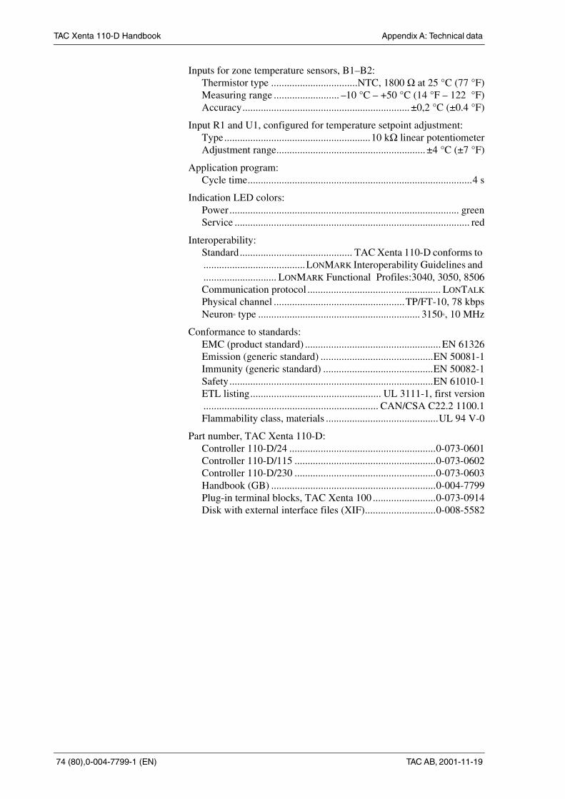
TAC Xenta 110-D Handbook Appendix A: Technical data
74 (80),0-004-7799-1 (EN) TAC AB, 2001-11-19
Inputs for zone temperature sensors, B1–B2:Thermistor type .................................NTC, 1800 Ω at 25 °C (77 °F)Measuring range ......................... –10 °C – +50 °C (14 °F – 122 °F)Accuracy................................................................ ±0,2 °C (±0.4 °F)
Input R1 and U1, configured for temperature setpoint adjustment:Type........................................................10 kΩ linear potentiometerAdjustment range......................................................... ±4 °C (±7 °F)
Application program:Cycle time......................................................................................4 s
Indication LED colors:Power........................................................................................ greenService .......................................................................................... red
Interoperability:Standard........................................... TAC Xenta 110-D conforms to.......................................LONMARK Interoperability Guidelines and............................ LONMARK Functional Profiles:3040, 3050, 8506Communication protocol ................................................... LONTALK
Physical channel ..................................................TP/FT-10, 78 kbpsNeuron® type .............................................................. 3150®, 10 MHz
Conformance to standards:EMC (product standard) ....................................................EN 61326Emission (generic standard) ...........................................EN 50081-1Immunity (generic standard) ..........................................EN 50082-1Safety..............................................................................EN 61010-1ETL listing.................................................. UL 3111-1, first version................................................................... CAN/CSA C22.2 1100.1Flammability class, materials ...........................................UL 94 V-0
Part number, TAC Xenta 110-D:Controller 110-D/24 ........................................................0-073-0601Controller 110-D/115 ......................................................0-073-0602Controller 110-D/230 ......................................................0-073-0603Handbook (GB) ...............................................................0-004-7799Plug-in terminal blocks, TAC Xenta 100 ........................0-073-0914Disk with external interface files (XIF)...........................0-008-5582

TAC Xenta 110-D Handbook Appendix B: Commissioning protocol
TAC AB, 2001-11-19 0-004-7799-1 (EN), 75 (80)
Appendix B: Commissioning protocolThis protocol can be used when commissioning the TAC Xenta 110-D.Note: The variables are listed in numerical order, not in the order follo-wed during commissioning. If you need information on accepted valu-es, these can be found in tables in chapter 6.
Index Function Variable Default value Set value Remarks
0 Configuration location label nciLocation 0
2 Lamp command 1 nviLampvalue1 state: 255value: 0%
3 Occupancy scheduler input 1 nviOccupancy1 OC_NUL
5 Lamp command 2 nviLampvalue2 state: 255value: 0%
6 Occupancy scheduler input 2 nviOccupancy2 OC_NUL
8 Lamp command 3 nviLampvalue3 state: 255value: 0%
9 Occupancy scheduler input 3 nviOccupancy3 OC_NUL
11 Lamp command 4 nviLampvalue4 state: 255value: 0%
12 Occupancy scheduler input 4 nviOccupancy4 OC_NUL
14 Lux level input nviLuxLevel 65535
15 Lamp control settings nviSetting SET_OFF
28 Occupancy scheduler inputSCC#1
nviOccManCmd1 OC_NUL
29 Zone temperature inputSCC#1
nviSpaceTemp1 327,67 °C(invalid value)
30 Setpoint offset input SCC#1 nviSetpntOffset1 0 °C
31 Heat control input for slaveSCC#1
nviHeatPriSlave1 163.84%(invalid value)
32 Cool control input for slaveSCC#1
nviCoolPriSlave1 163.84%(invalid value)
33 Occupancy sensor inputSCC#1
nviOccSensor1 OC_NUL
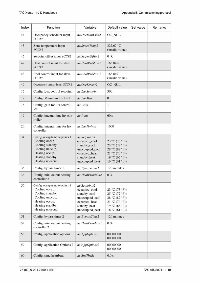
TAC Xenta 110-D Handbook Appendix B: Commissioning protocol
76 (80),0-004-7799-1 (EN) TAC AB, 2001-11-19
44 Occupancy scheduler inputSCC#2
nviOccManCmd2 OC_NUL
45 Zone temperature inputSCC#2
nviSpaceTemp2 327,67 °C(invalid value)
46 Setpoint offset input SCC#2 nviSetpntOffset2 0 °C
47 Heat control input for slaveSCC#2
nviHeatPriSlave2 163.84%(invalid value)
48 Cool control input for slaveSCC#2
nviCoolPriSlave2 163.84%(invalid value)
49 Occupancy sensor input SCC#2 nviOccSensor2 OC_NUL
16 Config. Lux control setpoint nciLuxSetpoint 300
17 Config. Minimum lux level nciLuxMin 0
18 Config. gain for lux control-ler
nciGain 1
19 Config. integral time lux con-troller
nciItime 60 s
20 Config. integral time for luxcontroller
nciLuxPerVolt 1000
34 Config. occup temp setpoints 1(Cooling occup.(Cooling standby(Cooling unocup.(Heating occup.(Heating standby(Heating unoccup.
nciSetpoints1occupied_coolstandby_coolunoccupied_cooloccupied_heatstandby_heatunoccupied_heat
23 °C (73 °F))25 °C (77 °F))28 °C (82 °F))21 °C (70 °F))19 °C (66 °F))16 °C (61 °F))
35 Config. bypass timer 1 nciBypassTime1 120 minutes
36 Config. min. output heatingcontroller 2
nciHeatPrimMin2 0 %
50 Config. occup temp setpoints 1(Cooling occup.(Cooling standby(Cooling unocup.(Heating occup.(Heating standby(Heating unoccup.
nciSetpoints2occupied_coolstandby_coolunoccupied_cooloccupied_heatstandby_heatunoccupied_heat
23 °C (73 °F))25 °C (77 °F))28 °C (82 °F))21 °C (70 °F))19 °C (66 °F))16 °C (61 °F))
51 Config. bypass timer 2 nciBypassTime2 120 minutes
52 Config. min. output heatingcontroller 2
nciHeatPrimMin1 0 %
58 Config. application options nciAppOptions 0000000000000000
59 Config. application Options 2 nciAppOptions2 0000000000000000
60 Config. send heartbeat nciSndHrtBt 0.0 s
Index Function Variable Default value Set value Remarks
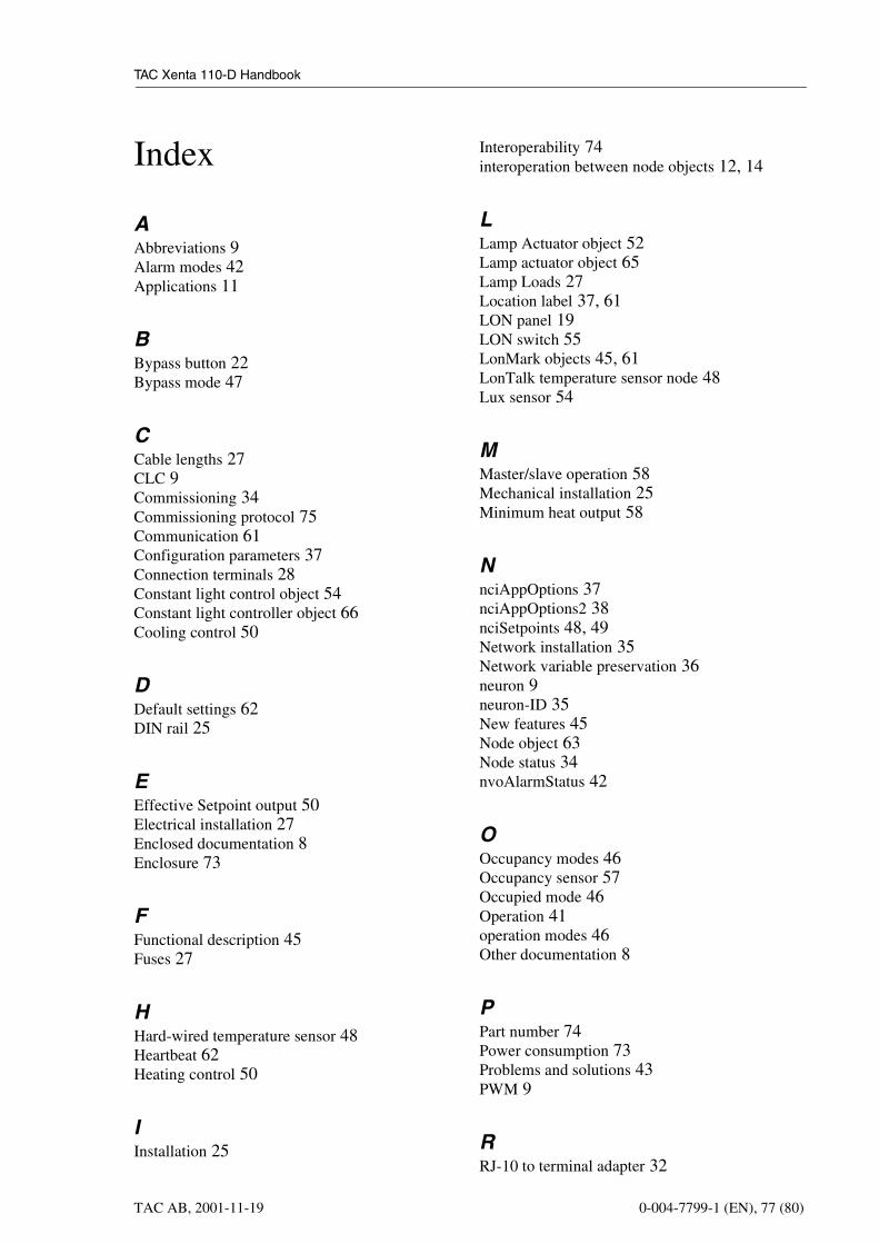
TAC Xenta 110-D Handbook
TAC AB, 2001-11-19 0-004-7799-1 (EN), 77 (80)
Index
AAbbreviations 9Alarm modes 42Applications 11
BBypass button 22Bypass mode 47
CCable lengths 27CLC 9Commissioning 34Commissioning protocol 75Communication 61Configuration parameters 37Connection terminals 28Constant light control object 54Constant light controller object 66Cooling control 50
DDefault settings 62DIN rail 25
EEffective Setpoint output 50Electrical installation 27Enclosed documentation 8Enclosure 73
FFunctional description 45Fuses 27
HHard-wired temperature sensor 48Heartbeat 62Heating control 50
IInstallation 25
Interoperability 74interoperation between node objects 12, 14
LLamp Actuator object 52Lamp actuator object 65Lamp Loads 27Location label 37, 61LON panel 19LON switch 55LonMark objects 45, 61LonTalk temperature sensor node 48Lux sensor 54
MMaster/slave operation 58Mechanical installation 25Minimum heat output 58
NnciAppOptions 37nciAppOptions2 38nciSetpoints 48, 49Network installation 35Network variable preservation 36neuron 9neuron-ID 35New features 45Node object 63Node status 34nvoAlarmStatus 42
OOccupancy modes 46Occupancy sensor 57Occupied mode 46Operation 41operation modes 46Other documentation 8
PPart number 74Power consumption 73Problems and solutions 43PWM 9
RRJ-10 to terminal adapter 32
TAC Xenta 110-D Handbook
TAC AB, 2001-11-19 0-004-7799-1 (EN), 78 (80)
SSafety standard 27SCC 9Send heartbeat 37service pin 9Setpoint offset input 49, 50SNVT 9Space Comfort controller 46Space comfort controller object 68stand-alone operation 46Standards 74Standby mode 47Supply voltage 73
TTAC Vista ScreenMate 23TAC Xenta Network Guide 8Technical data 73Terminology 9Thermal actuators 50Toggle light switch 55
UUnoccupied mode 47
WWall module 22wink 9Wiring of TAC Xenta 110-D/115 30Wiring of TAC Xenta 110-D/230 31Wiring of TAC Xenta 110-D/24 29
ZZone temperature control 48Zone temperature setpoints 48


UK I l d
Today we spend 90 percent of our time indoors. TAC helps us all to feel and function better - as a direct result of greater comfort. This is made possible by TAC’s new con-cept for efficient buildings - Open Systems for Building IT™. This provides our clients with advantages such as energy savings, wider choice and greater flexibility, security and user friendliness.
Trademarks and registered trademarks are properties of their respektive owners. TAC Vista®,
TAC Menta® och TAC Xenta® are registered trademarks of TAC AB. LonWorks®, LonMark® and
LonTalk® are registered trademarks of the Echelon Corporation.
As a LonMark® Sponsor TAC takes an active part in providing Open Systems for Building IT™.