hands on relay school - ieeeewh.ieee.org/soc/pes/newyork/newsite/pdfs/protection related... ·...
TRANSCRIPT
Hands On Relay SchoolTransformer Protection Open Lecture

Hands On Relay SchoolTransformer Protection Open Lecture
Class Outline• Transformer protection overview• Review transformer connections• Discuss challenges and methods of current
differential Protection• Discuss other protective elements used in
transformer protection
Scott CooperEastern Regional ManagerManta Test Systems
[email protected](727)415-5843
204 37th Avenue North #281Saint Petersburg, FL 33704
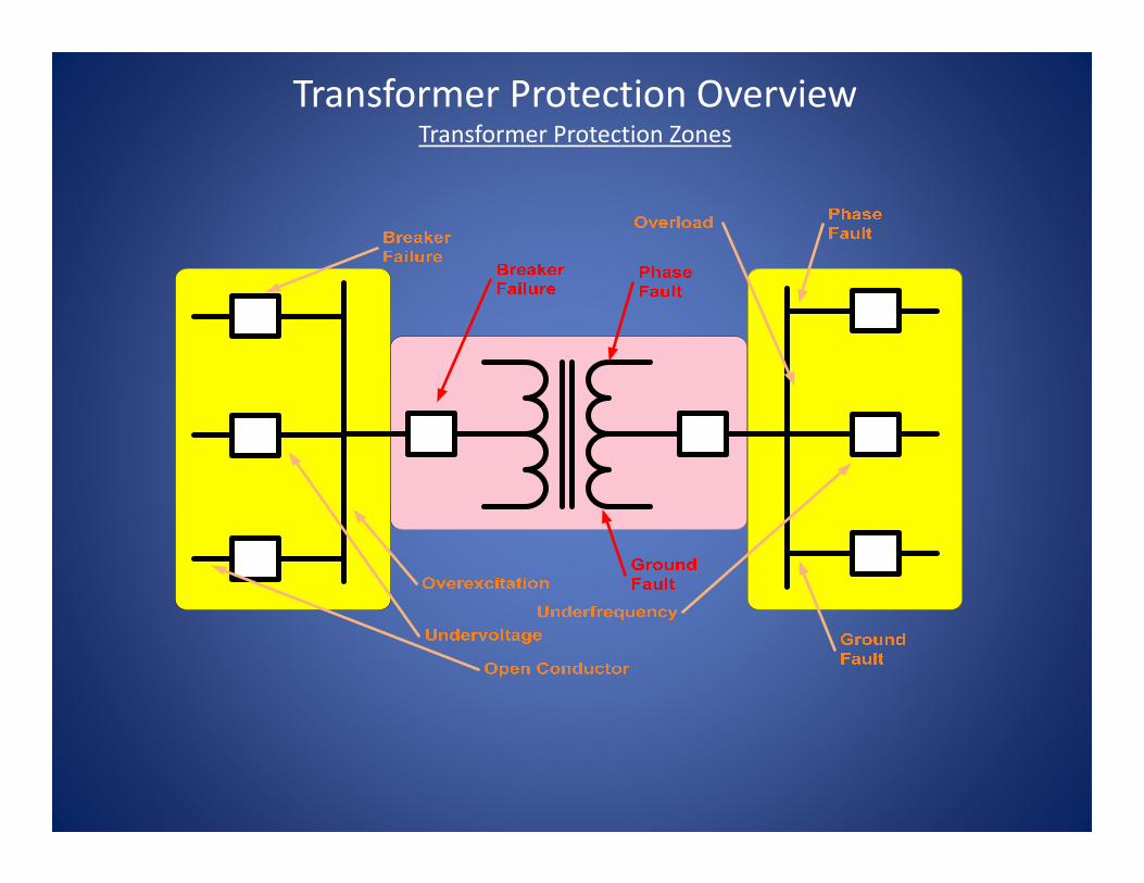
Transformer Protection Overview Transformer Protection Zones
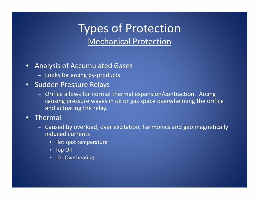
Types of ProtectionMechanical Protection
• Analysis of Accumulated Gases– Looks for arcing by‐products
• Sudden Pressure Relays– Orifice allows for normal thermal expansion/contraction. Arcing
causing pressure waves in oil or gas space overwhelming the orifice and actuating the relay.
• Thermal– Caused by overload, over excitation, harmonics and geo magnetically
induced currents• Hot spot temperature• Top Oil• LTC Overheating

Types of ProtectionRelay Protection
• Internal Short Circuit– Phase: 87HS, 87T– Ground: 87HS, 87T, 87GD
• System Short Circuit Back Up Protection– Phase and Ground Faults
• Buses: 50, 50N, 51, 51N, 46• Lines: 50, 50N, 51, 51N, 46
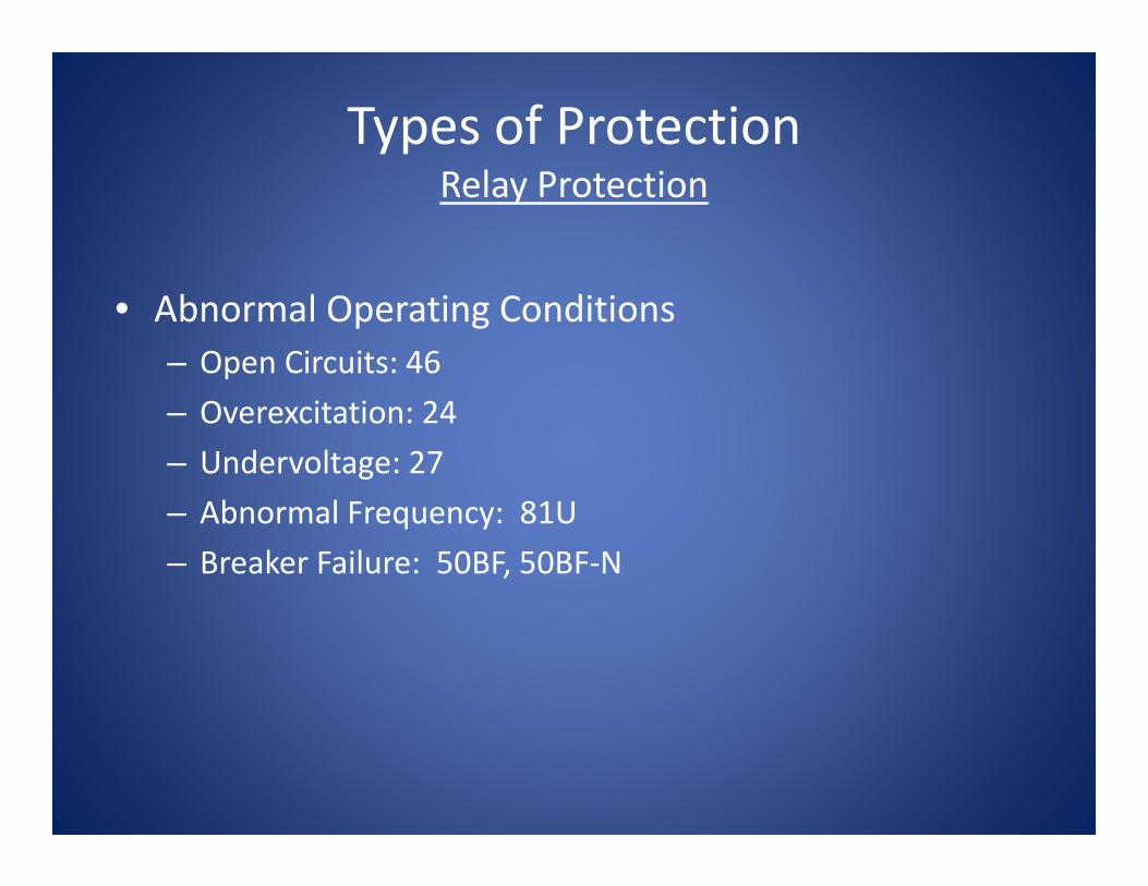
Types of ProtectionRelay Protection
• Abnormal Operating Conditions– Open Circuits: 46– Overexcitation: 24– Undervoltage: 27– Abnormal Frequency: 81U– Breaker Failure: 50BF, 50BF‐N

Phase DifferentialOverview
• What goes into a “unit” comes out of a “unit”
• Kirchoff’s Law: The sum of the currents entering and leaving a junction is (should be) zero
• Straight forward concept, but not that simple in practice with transformers
UNITI1 I2
I3
I1 + I2 + I3 = 0
Phase DifferentialOverview
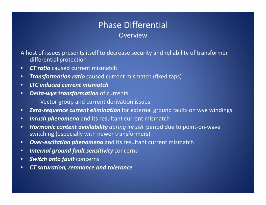
A host of issues presents itself to decrease security and reliability of transformer differential protection
• CT ratio caused current mismatch• Transformation ratio caused current mismatch (fixed taps)• LTC induced current mismatch• Delta‐wye transformation of currents
– Vector group and current derivation issues• Zero‐sequence current elimination for external ground faults on wye windings• Inrush phenomena and its resultant current mismatch• Harmonic content availability during inrush period due to point‐on‐wave
switching (especially with newer transformers)• Over‐excitation phenomena and its resultant current mismatch• Internal ground fault sensitivity concerns• Switch onto fault concerns• CT saturation, remnance and tolerance

Compensation (2)Change in CT Ratio 1:1, Y-Y
1:1, 3Y4:1, 3Y
IA, IB, IC Ia, Ib, Ic
IA'*4 = Ia'IB' * 4 = Ib'IC' * 4 = Ic'
IA', IB', IC' Ia', Ib', Ic'
Phase DifferentialOverview‐Transformer Basics
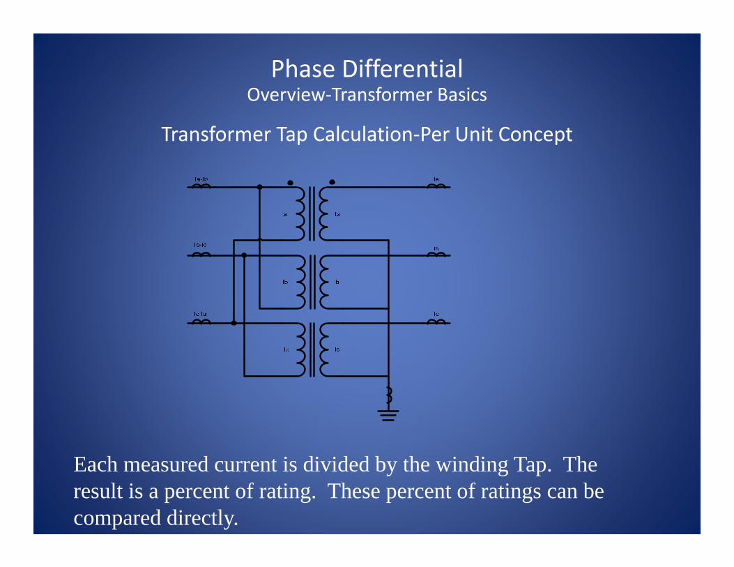
Transformer Tap Calculation‐Per Unit Concept
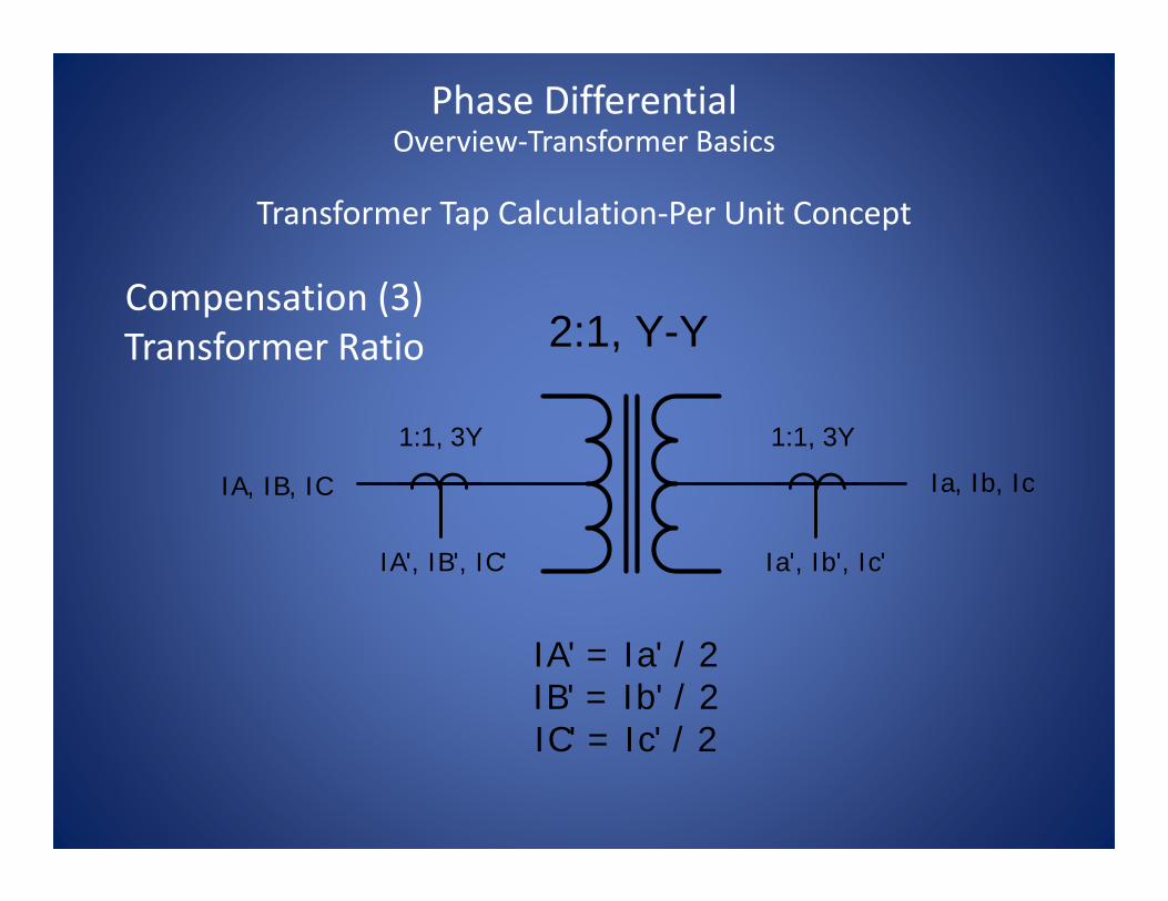
Compensation (3)Transformer Ratio 2:1, Y-Y
1:1, 3Y1:1, 3Y
IA, IB, IC Ia, Ib, Ic
IA' = Ia' / 2IB' = Ib' / 2IC' = Ic' / 2
IA', IB', IC' Ia', Ib', Ic'
Phase DifferentialOverview‐Transformer Basics
Transformer Tap Calculation‐Per Unit Concept
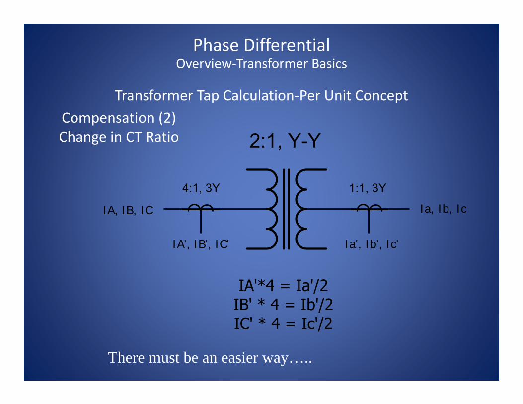
Compensation (2)Change in CT Ratio
IA, IB, IC Ia, Ib, Ic
IA', IB', IC' Ia', Ib', Ic'
Phase DifferentialOverview‐Transformer Basics
Transformer Tap Calculation‐Per Unit Concept
There must be an easier way…..

Transformer Tap Calculation‐Per Unit Concept
Phase DifferentialOverview‐Transformer Basics
100MVAIN
100MVAOUT
Transformer Tap Calculation‐Per Unit Concept
Phase DifferentialOverview‐Transformer Basics
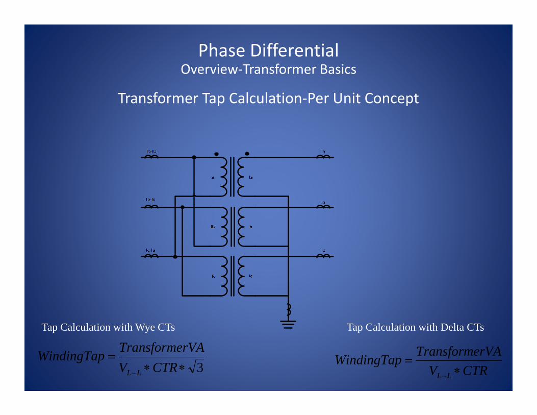
3∗∗=
− CTRVrVATransformeWindingTap
LL CTRVrVATransformeWindingTap
LL ∗=
−
Tap Calculation with Delta CTsTap Calculation with Wye CTs
Transformer Tap Calculation‐Per Unit Concept
Phase DifferentialOverview‐Transformer Basics
Each measured current is divided by the winding Tap. The result is a percent of rating. These percent of ratings can be compared directly.

AB connected delta‐wye transformer
Phase DifferentialOverview‐Transformer Basics
a
b
c -b
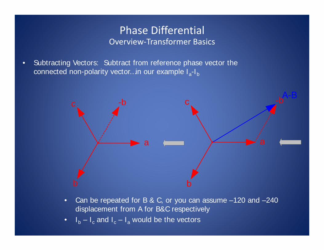
• Subtracting Vectors: Subtract from reference phase vector the connected non-polarity vector…in our example Ia-Ib
• Can be repeated for B & C, or you can assume –120 and –240 displacement from A for B&C respectively
• Ib – Ic and Ic – Ia would be the vectors
Phase DifferentialOverview‐Transformer Basics
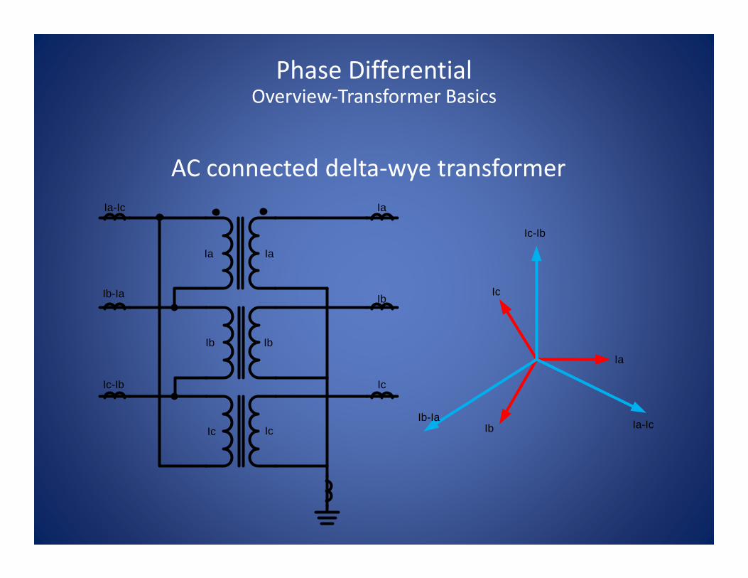
AC connected delta‐wye transformer
Ia Ia
Ib Ib
IcIc
Ia
Ib
Ic
Ia-Ic
Ib-Ia
Ic-Ib
Ia
Ia-IcIb
Ic
Ib-Ia
Ic-Ib
Phase DifferentialOverview‐Transformer Basics

• Subtracting vectors: Subtract from reference phase vector the connected non-polarity vector…in our example Ia-Ic
• Can be repeated for B & C, or you can assume –120 and –240 displacement from A for B&C respectively
• Ib – Ia and Ic – Ib would be the vectors
a
b
c
-c
Phase DifferentialOverview‐Transformer Basics
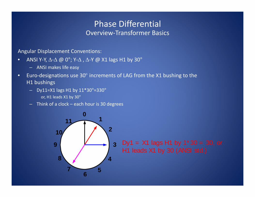
Angular Displacement Conventions:• ANSI Y‐Y, Δ‐Δ@ 0°; Y‐Δ , Δ‐Y @ X1 lags H1 by 30°
– ANSI makes life easy
• Euro‐designations use 30° increments of LAG from the X1 bushing to the H1 bushings
– Dy11=X1 lags H1 by 11*30°=330°or, H1 leads X1 by 30°
– Think of a clock – each hour is 30 degrees
0
6
39
8
7
10
11 12
5
4
Dy1 = X1 lags H1 by 1*30 = 30, or H1 leads X1 by 30 (ANSI std.)
Phase DifferentialOverview‐Transformer Basics

US Standard Dy Example:• H1 (A) leads X1 (a) by 30• Currents on “H” bushings are delta quantities
a
b
c A
B
C
Assume 1:1 transformer
Phase DifferentialOverview‐Transformer Basics

Assume 1:1 transformer
a
b
c
AB
C
Phase DifferentialOverview‐Transformer Basics
US Standard Yd Example:•H1 (a) leads X1 (A) by 30•Currents on “X” bushings are delta quantities
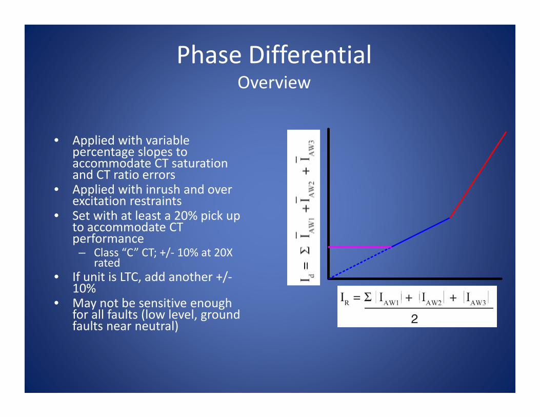
Phase DifferentialOverview
• Applied with variable percentage slopes to accommodate CT saturation and CT ratio errors
• Applied with inrush and over excitation restraints
• Set with at least a 20% pick up to accommodate CT performance– Class “C” CT; +/‐ 10% at 20X
rated• If unit is LTC, add another +/‐
10%• May not be sensitive enough
for all faults (low level, ground faults near neutral)
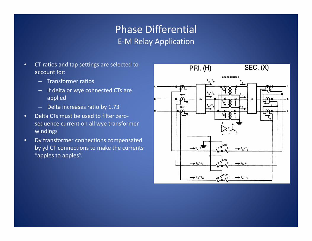
• CT ratios and tap settings are selected to account for:
– Transformer ratios– If delta or wye connected CTs are
applied– Delta increases ratio by 1.73
• Delta CTs must be used to filter zero‐sequence current on all wye transformer windings
• Dy transformer connections compensated by yd CT connections to make the currents “apples to apples”.
Phase DifferentialE‐M Relay Application

Zero‐sequence elimination: In E‐M relays with wye connected transformers, delta connected CTs are used to remove the ground current.
Phase DifferentialE‐M Relay Application

Settings compensate for the following:• Transformer ratio• CT ratio• Vector quantities
– Which vectors are used– Where the 1.73 factor (√3) is applied
• When examining line to line quantities on delta connected transformer windings and CT windings
• Zero‐sequence current filtering for wye windings so the differential quantities do not occur from external ground faults
Phase DifferentialDigital Relay Application

Angular displacement (IEC and SEL)• IEC (Euro) practice does not
have a standard like ANSI• Most common connection is
Dy11 (low lead high by 30!)• Obviously observation of
angular displacement is extremely important when paralleling transformers!
*1
*1
*2
*2
*1 = ANSI std. @ 0°
*2 = ANSI std. @ X1 lag H1 by 30°, or “high lead low by 30 ° “
Phase DifferentialDigital Relay Application

Digital Relay Application
All wye CTs shown, most can retrofit legacy delta CT applications

Benefits of Wye CTs
• Phase segregated line currents– Individual line current oscillography– Currents may be easily used for overcurrent protection and metering
– Easier to commission and troubleshoot– Zero sequence elimination performed by calculation

Zero‐sequence elimination: In digital relays with wye connected transformers and wye connected CTs, ground current must be removed from the differential calculation.
•3I0 = [Ia + Ib + Ic]I0 = 1/3 *[Ia + Ib + Ic]
•Used where filtering is required, such as wyewinding with wye CTs
Phase DifferentialDigital Relay Application
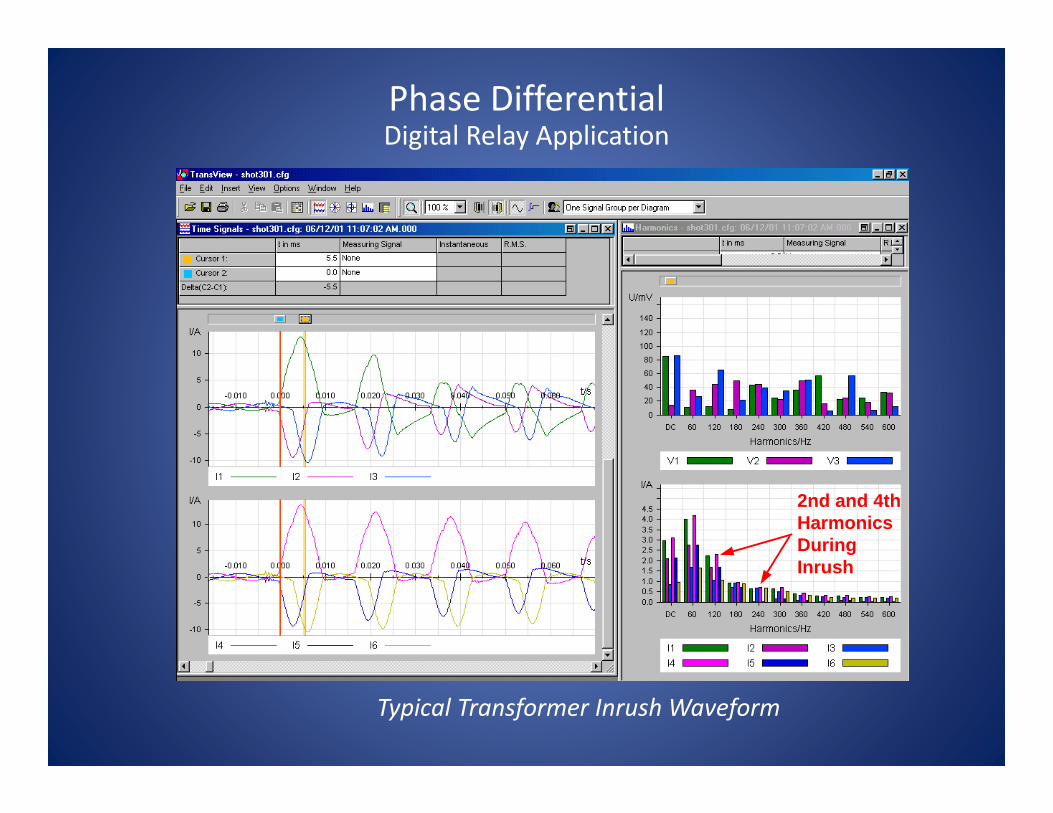
Typical Transformer Inrush Waveform
2nd and 4thHarmonicsDuringInrush
Phase DifferentialDigital Relay Application

Harmonically Restrained Differential Element• Inrush Detection and Restraint
– Inrush occurs on transformer energizing as the core magnetizes– Sympathy inrush occurs from adjacent transformer(s) energizing, fault
removal, allowing the transformer to undergo a low level inrush– Characterized by current into one winding of transformer, and not out
of the other winding(s)– This causes the differential element to pickup– Use inrush restraint to block differential element during inrush period
Phase DifferentialDigital Relay Application

• Inrush Detection and Restraint– 2nd harmonic restraint has been employed for years– “Gap” detection has also been employed– As transformers are designed to closer tolerances, both 2nd harmonic
and low current gaps in waveform have decreased– If 2nd harmonic restraint level is set too low, differential element may
be blocked for internal faults with CT saturation (with associated harmonics generated)
Phase DifferentialDigital Relay Application
• Inrush Detection and Restraint– 4th harmonic is also generated during inrush– Odd harmonics are not as prevalent as Even harmonics during inrush– Odd harmonics more prevalent during CT saturation– Use 4th harmonic and 2nd harmonic together– M‐3310/M‐3311 relays use RMS sum of the 2nd and 4th harmonic as
inrush restraint– Result: Improved security while not sacrificing reliability
Phase DifferentialDigital Relay Application

• Overexcitation Restraint– Overexcitation occurs when volts per hertz level rises (V/Hz)
– This typically occurs from load rejection and malfunctioning generation AVRs
– The voltage rise at nominal frequency causes the V/Hz to rise
– This causes 5th harmonics to be generated in the transformer as it begins to go into saturation
– The current entering the transformer is more than the current leaving due to this increase in magnetizing current
– This causes the differential element to pick‐up– Use 5th harmonic level to detect overexcitation
Phase DifferentialDigital Relay Application

0.5
1.0
1.5
2.0
0.5 1.0 1.5 2.0
87T Pick Up
87T Pick Upwith 5th Harmonic Restraint
Slope 1
Slope 2
Slope 2Breakpoint
TRIP
RESTRAIN
Phase DifferentialDigital Relay Application
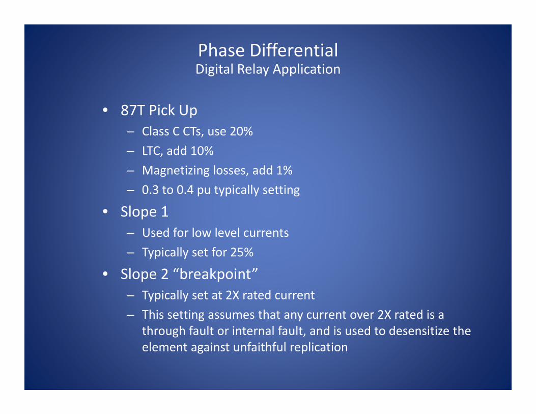
• 87T Pick Up– Class C CTs, use 20%– LTC, add 10%– Magnetizing losses, add 1%– 0.3 to 0.4 pu typically setting
• Slope 1– Used for low level currents– Typically set for 25%
• Slope 2 “breakpoint”– Typically set at 2X rated current– This setting assumes that any current over 2X rated is a
through fault or internal fault, and is used to desensitize the element against unfaithful replication
Phase DifferentialDigital Relay Application

• Slope 2– Typically set at 70%
• Inrush Restraint (2nd and 4th harmonic)– Typically set from 15‐20%– Employ cross phase averaging blocking for security
• Over‐excitation Restraint (5th harmonic)– Typically set at 30%– Raise 87T pick up to 0.60 pu during overexcitation– No cross phase averaging needed, as overexcitation is
symmetric on the phases
Phase DifferentialDigital Relay Application

• Unrestrained 87H Pick Up– Typically set at 8‐10pu rated current– This value should be above maximum possible inrush current
and lower than the CT saturation current– C37.91, section 5.2.3, states 10pu an acceptable value– Can use data captured from energizations to fine tune the
setting
Phase DifferentialDigital Relay Application
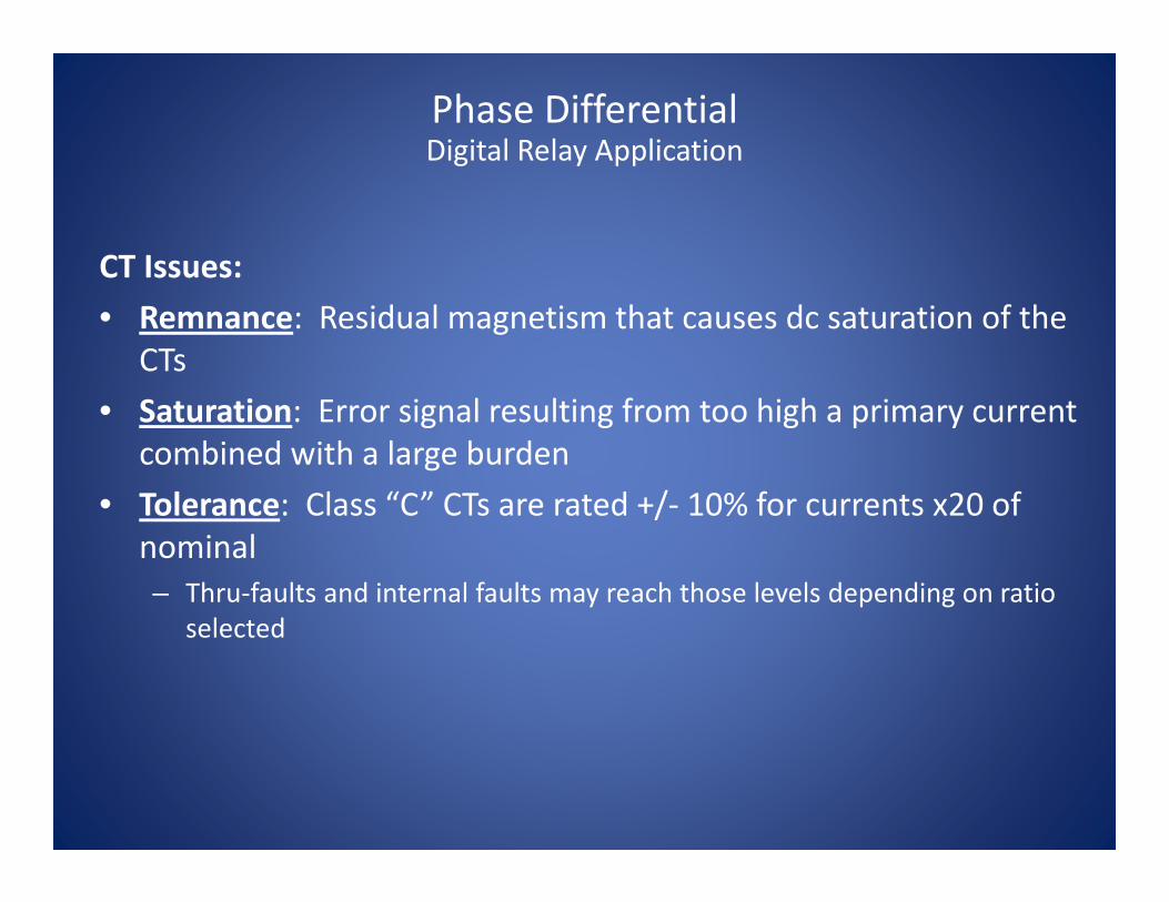
CT Issues:• Remnance: Residual magnetism that causes dc saturation of the
CTs• Saturation: Error signal resulting from too high a primary current
combined with a large burden• Tolerance: Class “C” CTs are rated +/‐ 10% for currents x20 of
nominal – Thru‐faults and internal faults may reach those levels depending on ratio
selected
Phase DifferentialDigital Relay Application

CT Issues (cont.)• Best defense is to use high “Class C” voltage levels
– C400, C800– These have superior characteristics against saturation and relay/wiring
burden• Use low burden relays
– Digital systems are typically 0.020 ohms• Use a variable percentage slope characteristic to desensitize
the differential element when challenged by high currents that may cause replication errors
Phase DifferentialDigital Relay Application

“Point‐on‐Wave” Considerations During Energization• As most circuit breakers are ganged three‐pole, each phase is closed at a
different angle resulting in less harmonics on one phase and more on the others
• Low levels of harmonics may not provide inrush restraint for affected phase –security risk!
• Most modern relays employ some kind of cross‐phase averaging scheme to compensate for this issue
– Provides security if any phase has low harmonic content during inrush or overexcitation– This can occur depending on the voltage point‐on‐wave when the transformer is energized for a
given phase– Cross phase averaging uses the average of harmonics on all three phases to determine level
Phase DifferentialDigital Relay Application

Improved Ground Fault Sensitivity:• 87T element is typically set with 20‐40% pick up• This is to accommodate Class “C” CT accuracy
during a fault plus the effects of LTCs• That leaves 20‐40% of the winding not covered for
a ground fault• Employ a ground differential element to improve
sensitivity (87GD)
Phase DifferentialDigital Relay Application
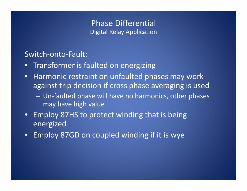
Switch‐onto‐Fault:• Transformer is faulted on energizing• Harmonic restraint on unfaulted phases may work against trip decision if cross phase averaging is used– Un‐faulted phase will have no harmonics, other phases may have high value
• Employ 87HS to protect winding that is being energized
• Employ 87GD on coupled winding if it is wye
Phase DifferentialDigital Relay Application
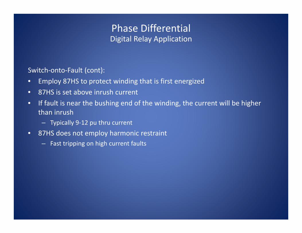
Switch‐onto‐Fault (cont):• Employ 87HS to protect winding that is first energized• 87HS is set above inrush current• If fault is near the bushing end of the winding, the current will be higher
than inrush– Typically 9‐12 pu thru current
• 87HS does not employ harmonic restraint– Fast tripping on high current faults
Phase DifferentialDigital Relay Application

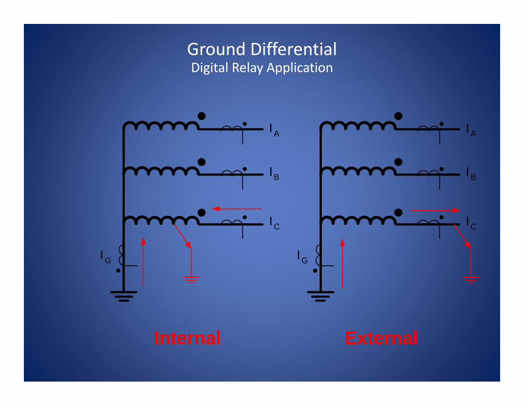
• Use 87GD• IA + IB + IC = 3I0
• If fault is internal, opposite polarity
• If fault is external, same polarity
IG
IA
IB
IC
Ground DifferentialDigital Relay Application
IG
IA
IB
IC
IG
IA
IB
IC
Internal External
Ground DifferentialDigital Relay Application
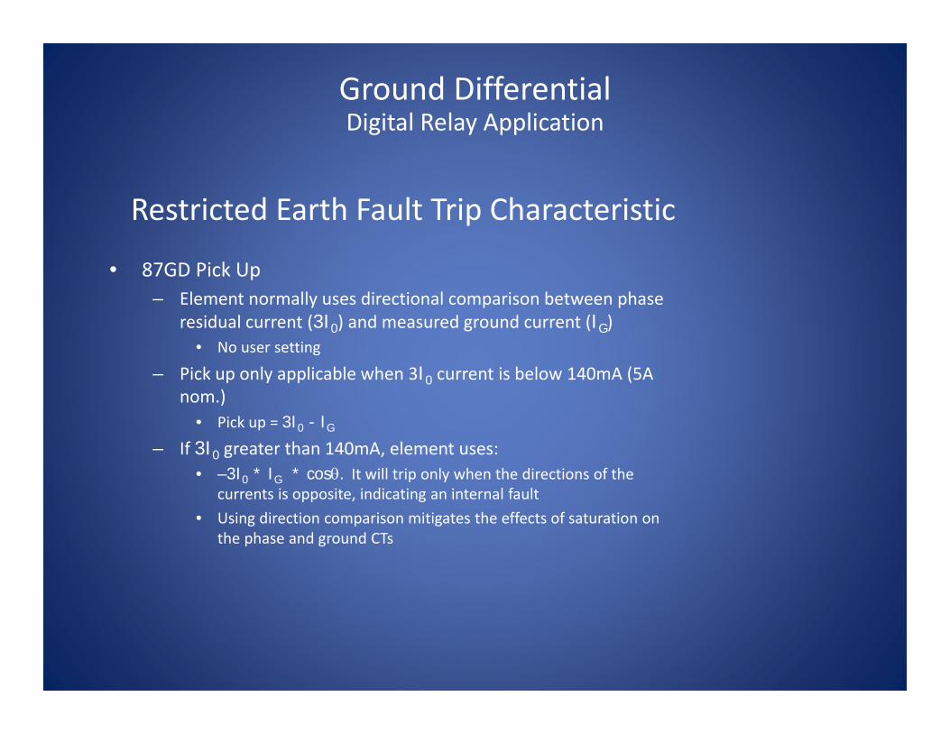
Restricted Earth Fault Trip Characteristic
• 87GD Pick Up– Element normally uses directional comparison between phase
residual current (3I0) and measured ground current (IG)• No user setting
– Pick up only applicable when 3I0 current is below 140mA (5A nom.)
• Pick up = 3I0 - IG
– If 3I0 greater than 140mA, element uses:• –3I0 * IG * cosθ. It will trip only when the directions of the
currents is opposite, indicating an internal fault• Using direction comparison mitigates the effects of saturation on
the phase and ground CTs
Ground DifferentialDigital Relay Application

IG
IA
IB
IC
3I0IG
Residual currentcalculated fromindividual phasecurrents. ParalleledCTs shown toillustrate principle.
0
90
180
270
IG
-3IO
Ground DifferentialDigital Relay Application

0
90
180
270
IG
-3IO
Ground DifferentialDigital Relay Application

• Fuses– Small transformers ( <10 MVA)– Short circuit protection only
• Over current protection– H‐side
• Through fault protection• Differential back‐up protection for high side faults
– X‐side• System back up protection• Unbalanced load protection
Other Transformer ProtectionOver current Elements
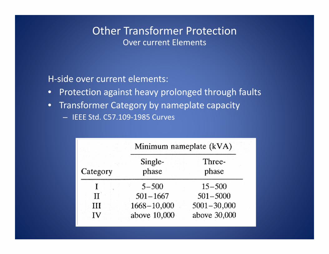
H‐side over current elements:• Protection against heavy prolonged through faults• Transformer Category by nameplate capacity
– IEEE Std. C57.109‐1985 Curves
Other Transformer ProtectionOver current Elements

Cat. 2 & 3 Fault Frequency
Zones
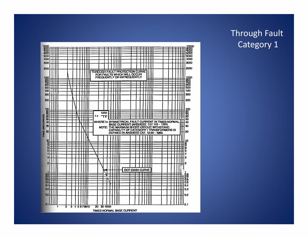
Through Fault Category 1
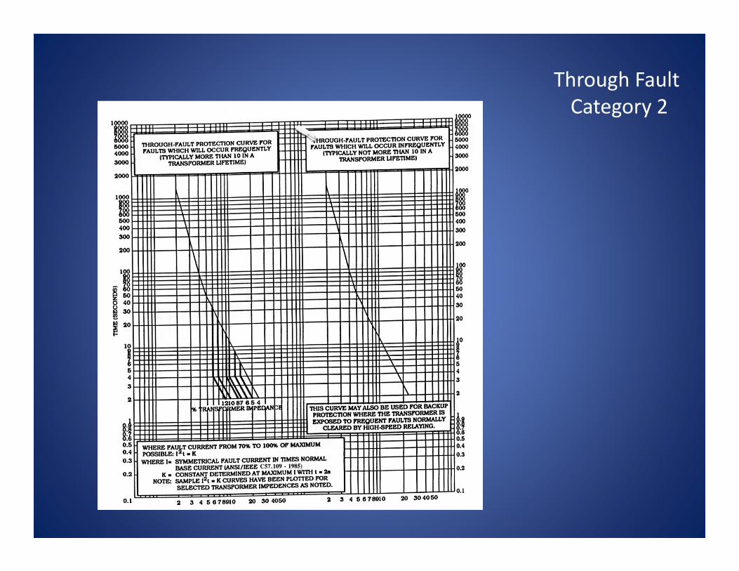
Through Fault Category 2
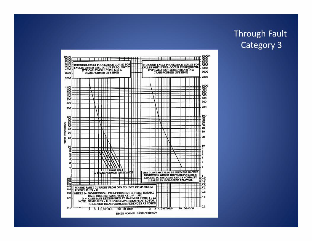
Through Fault Category 3
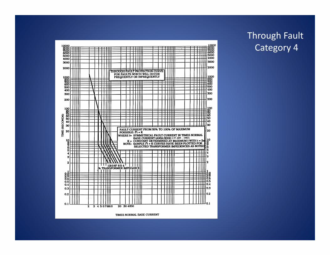
Through Fault Category 4

X‐side Over Current Elements
• Used to protect against un‐cleared faults downstream of the transformer
• May consist of phase and ground elements
• Coordinated with line protection off the bus Failed Breaker
5151G
Other Transformer ProtectionOver current Elements

X‐side Over Current Elements:• Negative sequence over
current used to protect against unbalanced loads & open conductors
• Easy to coordinate46
Other Transformer ProtectionOver current Elements
• Overexcitation:– Responds to overfluxing; excessive v/Hz– Continuous operational limits
• ANSI C37.106 & C57.12– 1.05 loaded, 1.10 unloaded
• Inverse curves typically available for values over the continuous allowable maximum
Other Transformer ProtectionOver current Elements

Causes:• Generating Plants
– Excitation system runaway – Sudden loss of load– Operational issues (reduced frequency)
• Static starts• Pumped hydro starting• Rotor warming
• Transmission Systems– Voltage and Reactive Support Control Failures
• Capacitor banks ‘ON’ when they should be ‘OFF’• Shunt reactors ‘OFF’ when they should be ‘ON’• Generator unit transformer connected to long line with no‐load (Ferranti effect)
• Runaway LTCs
Other Transformer ProtectionOver current Elements

Overexcitation Curve
This is typically how the apparatus manufacturer specs it

Overexcitation Curve
This is how protection engineers enter the v/Hz curve into a protective device
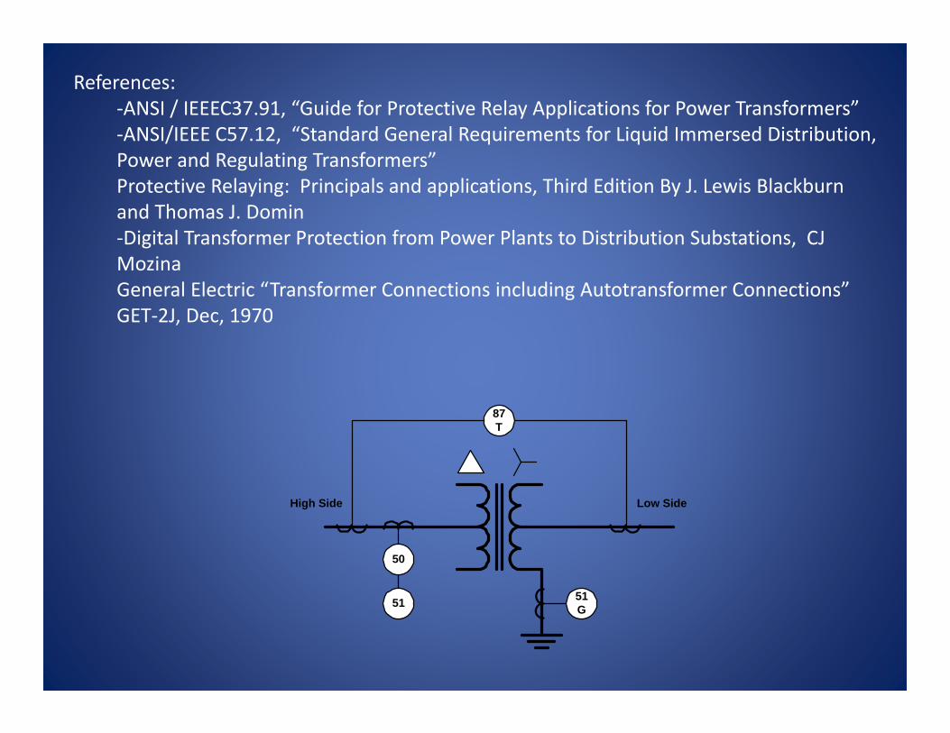
References:‐ANSI / IEEEC37.91, “Guide for Protective Relay Applications for Power Transformers”‐ANSI/IEEE C57.12, “Standard General Requirements for Liquid Immersed Distribution, Power and Regulating Transformers”Protective Relaying: Principals and applications, Third Edition By J. Lewis Blackburn and Thomas J. Domin‐Digital Transformer Protection from Power Plants to Distribution Substations, CJ MozinaGeneral Electric “Transformer Connections including Autotransformer Connections” GET‐2J, Dec, 1970
87T
50
51 51G
High Side Low Side