hangers and supports - spswestbehringer clamps are used in many different types of applications...
TRANSCRIPT

Hygienic Hangers and Supports
CH SeriesSmooth Bore Series
StanchionsHeight Adjusters
Accessories
Page 1 | www.behringersystems.com | 973-948-0226 | next | | previous |
Hygienic Hangers & SupportsTable of Contents
TOC |
Introduction . . . . . . . . . . . . . . . . . . . . . . . . . . . . . . . . . . . . . . . . . . . . . . . . . . . . . . . . . . . . . . . . . . . . . . . . . . 3Introduction Applications Product AssistanceGuarantee Please Read
CH Series . . . . . . . . . . . . . . . . . . . . . . . . . . . . . . . . . . . . . . . . . . . . . . . . . . . . . . . . . . . . . . . . . . . . . . . . . . . . . . . . 5CH-Dynamic Mount Hanger CHT-Rigid Threaded Mount HangerCHR-Rigid Mount Hanger Threaded Support RodCHW-Weld Plate Mount Support Tapered Guides
Smooth Bore Series . . . . . . . . . . . . . . . . . . . . . . . . . . . . . . . . . . . . . . . . . . . . . . . . . . . . . . . . . . . . . . . . . . . .30Mounting / Hardware Configuration Fig. 203 RAL-1 Rail MountingFig. 200 Weld Plate Mount Fig. 204 Stacking KitFig. 201 Hang Plate Mount Fig. 211 Unistrut Mount Fig. 202 Base Plate Mount Fig. 221 Rod Mount
Stanchions . . . . . . . . . . . . . . . . . . . . . . . . . . . . . . . . . . . . . . . . . . . . . . . . . . . . . . . . . . . . . . . . . . . . . . . . . . . 64Fig. 223 Telescopic Adjusting Round Floor StandFig. 224 CH Series Rod Stand Plate Fig. 225 Telescopic Adjusting Stanchion - Hang Mount Fig. 226 Telescopic Adjusting Stanchion - Floor Mount
Height Adjusters . . . . . . . . . . . . . . . . . . . . . . . . . . . . . . . . . . . . . . . . . . . . . . . . . . . . . . . . . . . . . . . . . 78Rigid Height AdjustersDynamic Height Adjusters
Accessories . . . . . . . . . . . . . . . . . . . . . . . . . . . . . . . . . . . . . . . . . . . . . . . . . . . . . . . . . . . . . . . . . . . . . . . . . . 82
Technical Data . . . . . . . . . . . . . . . . . . . . . . . . . . . . . . . . . . . . . . . . . . . . . . . . . . . . . . . . . . . . . . . . . . . . . 83Proper Slope for Drainability Slope Conversion ChartRecommended Mounting Practices Shear Force DiagramMaterial Properties Spacing of Hangers Surface Finishing for Metal Parts
Page 2 | www.behringersystems.com | 973-948-0226 | next | | previous |

IntroductionThank you for choosing Behringer, the world’s leading manufacturer of Pipe and Tube supports. Behringer has been manufacturing pipe clamps and support systems for over 30 years, and has developed a reputation in the industrial and sanitary markets that is second to none. We have made developments and product improvements over the years both strengthening and broadening our product offering. This is evident in the breadth of our line and ability to accommodate new applications and designs. You can count on Behringer for all your clamping and support requirements.
ProductBehringer Hygienic Tube Supports are designed to meet the high demands of process piping in hygienic service applications. The automatic slope adjustment feature of the CH Series Dynamic hanger will promote drainability of the piping without imparting unnecessary stress into the piping. Drainability is a critical design feature in hygienic process piping. Behringer Sanitary Pipe and Tube Supports are available in a wide range of sizes and configurations and are offered with both an anchor or guide insert to meet the needs of any application. Behringer offers many different series and within each series there are many different configurations available. We offer options for mounting such as welding, bolting, rail and strut mounting, double, and group mounting, etc. Behringer always welcomes a challenge, and would be happy to work with you to design a product that is custom-tailored to your application. This is where many of our developments are first generated, and helps to further progress the complexity of our product. Challenge us with your requirements.
GuaranteeBehringer Corporation, hereinafter called the “MANUFACTURER”, guarantees that this product shall be free from defects in workmanship and materials. THIS GUARANTEE IS IN LIEU OF ALL OTHER GUARANTEES EITHER EXPRESSED OR IMPLIED, INCLUDING GUARANTEES FOR FITNESSFOR PURPOSE INTENDED. The MANUFACTURER’S liability is limited to the replacement of any materials which, after inspection by the MANUFACTURER at its sole option, are found to be defective. The MANUFACTURER will honor only those claims that are presented to it within one hundred eighty (180) days of the delivery of the materials to the purchaser. The MANUFACTURER SPECIFICALLY DISCLAIMS ANY AND ALL LIABILITY FOR CONSEQUENTIAL DAMAGES. The MANUFACTURER shall not be liable for any damages which arise out of the misuse or abuse of the products.
IntroductionHANGERS & SUPPORTS
TOC |
Page 3 | www.behringersystems.com | 973-948-0226 | next | | previous |
IntroductionHANGERS & SUPPORTS
TOC |
ApplicationsBehringer clamps are used in many different types of applications ranging from low pressure lubrication and water systems to high pressure hydraulic and process systems. Anywhere that there are pipes, tubes, or hoses is a viable application for Behringer clamps. Behringer clamps are used in the following markets and applications most frequently:
Mobile Equipment Power GenerationMining Equipment Pulp and PaperOffshore and Marine Applications Industrial HydraulicsShipbuilding Power UnitsInstrumentation Agricultural EquipmentNuclear OEM MachineryGeneral ConstructionElectrical / Mechanical ContractingProcess PipingPharmaceutical / BiotechnologyFood and DairyBeverage
AssistanceBehringer Corporation has a competent and highly skilled staff of inside sales and customer service personnel available to assist you with any of your needs. Behringer can be reached in the following ways:
Post Mail: Behringer Corporation17 Ridge RoadBranchville, NJ 07826
Telephone:+1 (973) 948-0226
Fax:+1 (973) 948-2562
Email: [email protected]
Our regular business hours are Monday through Friday, 8AM - 5 PM Eastern Time. For after-hours service, please contact your regional sales manager.
Please ReadThe information contained in this document is provided as an aid in properly selecting products and/or options. It is intended to be used by technically experienced users for general reference only. The supplier assumes no responsibility or liability for the accuracy or completeness of this document, as well as results obtained by the use of this information. Due to the variety of possible operating conditions, it is highly recommended that the user make their own tests to determine the safety and suitability of all products and combinations thereof. The user is solely responsible for final determination of such conditions.
Page 4 | www.behringersystems.com | 973-948-0226 | next | | previous |
CH SeriesHANGER & SUPPORTS
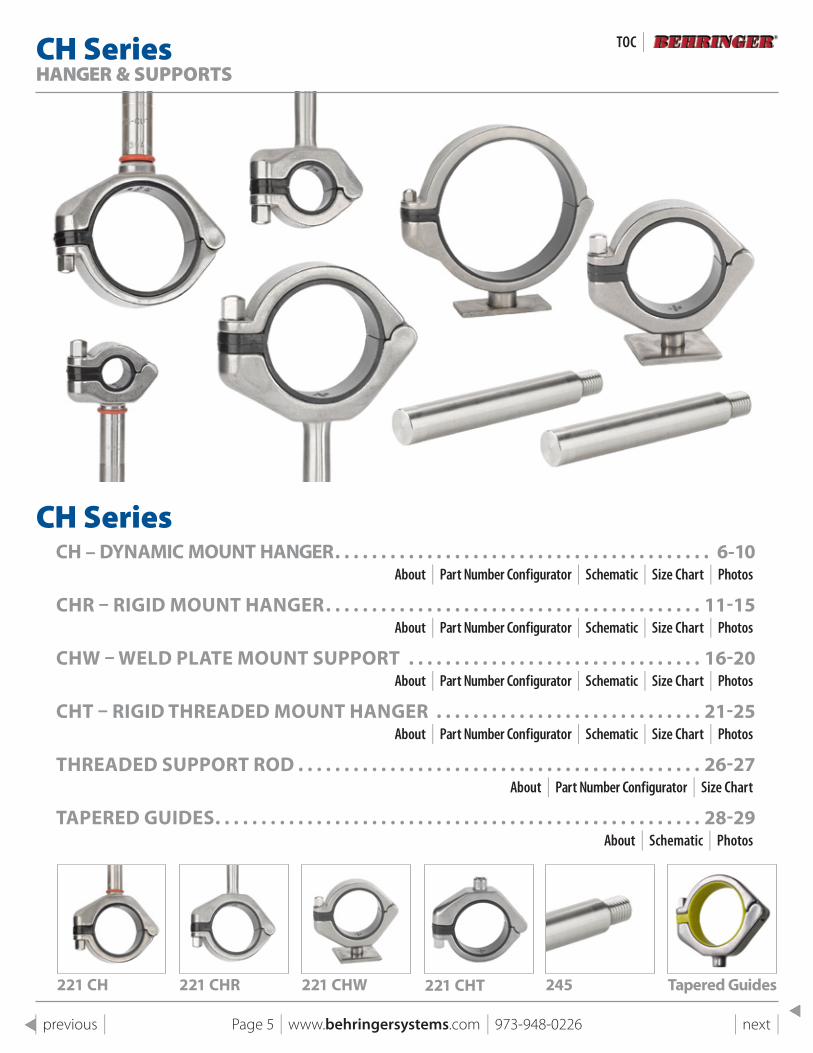
CH SeriesCH – DYNAMIC MOUNT HANGER . . . . . . . . . . . . . . . . . . . . . . . . . . . . . . . . . . . . . . . . . 6-10
About | Part Number Configurator | Schematic | Size Chart | Photos
CHR – RIGID MOUNT HANGER . . . . . . . . . . . . . . . . . . . . . . . . . . . . . . . . . . . . . . . . . 11-15About | Part Number Configurator | Schematic | Size Chart | Photos
CHW – WElD plATE MOUNT sUppORT . . . . . . . . . . . . . . . . . . . . . . . . . . . . . . . . 16-20About | Part Number Configurator | Schematic | Size Chart | Photos
CHT – RIGID THREADED MOUNT HANGER . . . . . . . . . . . . . . . . . . . . . . . . . . . . . 21-25About | Part Number Configurator | Schematic | Size Chart | Photos
THREADED sUppORT ROD . . . . . . . . . . . . . . . . . . . . . . . . . . . . . . . . . . . . . . . . . . . . 26-27About | Part Number Configurator | Size Chart
TApERED GUIDEs . . . . . . . . . . . . . . . . . . . . . . . . . . . . . . . . . . . . . . . . . . . . . . . . . . . . . 28-29About | Schematic | Photos
221 CH 221 CHR 221 CHW 221 CHT 245 Tapered Guides
Page 5 | www.behringersystems.com | 973-948-0226 | next | | previous |
TOC |
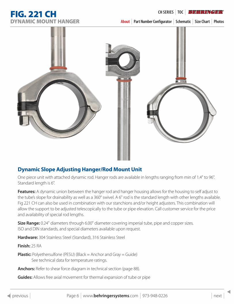
FIG . 221 CHDYNAMIC MOUNT HANGER About | Part Number Configurator | Schematic | Size Chart | Photos
Dynamic slope Adjusting Hanger/Rod Mount UnitOne piece unit with attached dynamic rod. Hanger rods are available in lengths ranging from min of 1.4" to 96". Standard length is 6".
Features: A dynamic union between the hanger rod and hanger housing allows for the housing to self adjust to the tube’s slope for drainability as well as a 360° swivel. A 6" rod is the standard length with other lengths available. Fig 221 CH can also be used in combination with our stanchions and/or height adjusters. This combination will allow the support to be adjusted telescopically to the tube or pipe elevation. Call customer service for the price and availability of special rod lengths.
Size Range: 0.24" diameters through 6.00" diameter covering imperial tube, pipe and copper sizes. ISO and DIN standards, and special diameters available upon request.
Hardware: 304 Stainless Steel (Standard), 316 Stainless Steel
Finish: 25 RA
Plastic: Polyethersulfone (PESU) (Black = Anchor and Gray = Guide) See technical data for temperature ratings.
Anchors: Refer to shear force diagram in technical section (page 88).
Guides: Allows free axial movement for thermal expansion of tube or pipe
Page 6 | www.behringersystems.com | 973-948-0226 | next | | previous |
CH SeRIeS | TOC |
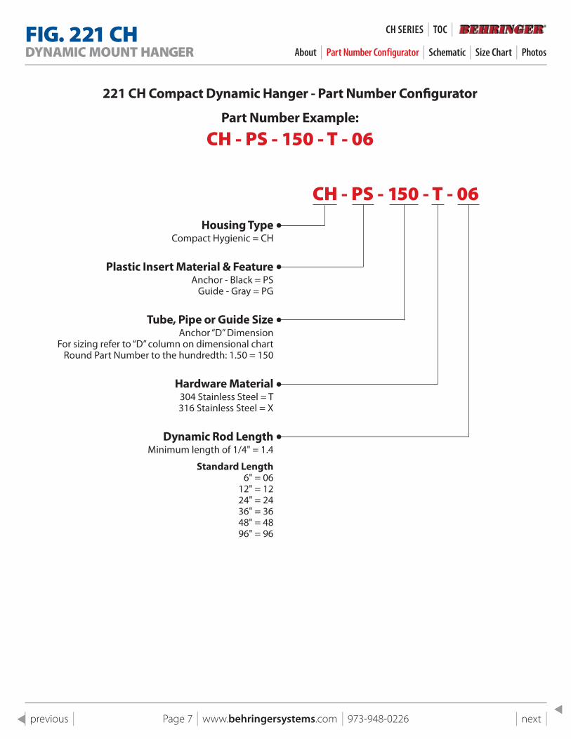
FIG . 221 CHDYNAMIC MOUNT HANGER About | Part Number Configurator | Schematic | Size Chart | Photos
CH - PS - 150 - T - 06
221 CH Compact Dynamic Hanger - part Number Configurator
part Number Example:
CH - PS - 150 - T - 06
Housing TypeCompact Hygienic = CH
plastic Insert Material & FeatureAnchor - Black = PS
Guide - Gray = PG
Tube, pipe or Guide sizeAnchor “D” Dimension
For sizing refer to “D” column on dimensional chartRound Part Number to the hundredth: 1.50 = 150
Hardware Material304 Stainless Steel = T 316 Stainless Steel = X
Dynamic Rod lengthMinimum length of 1/4" = 1.4
standard length6" = 06
12" = 1224" = 2436" = 3648" = 4896" = 96
Page 7 | www.behringersystems.com | 973-948-0226 | next | | previous |
CH SeRIeS | TOC |
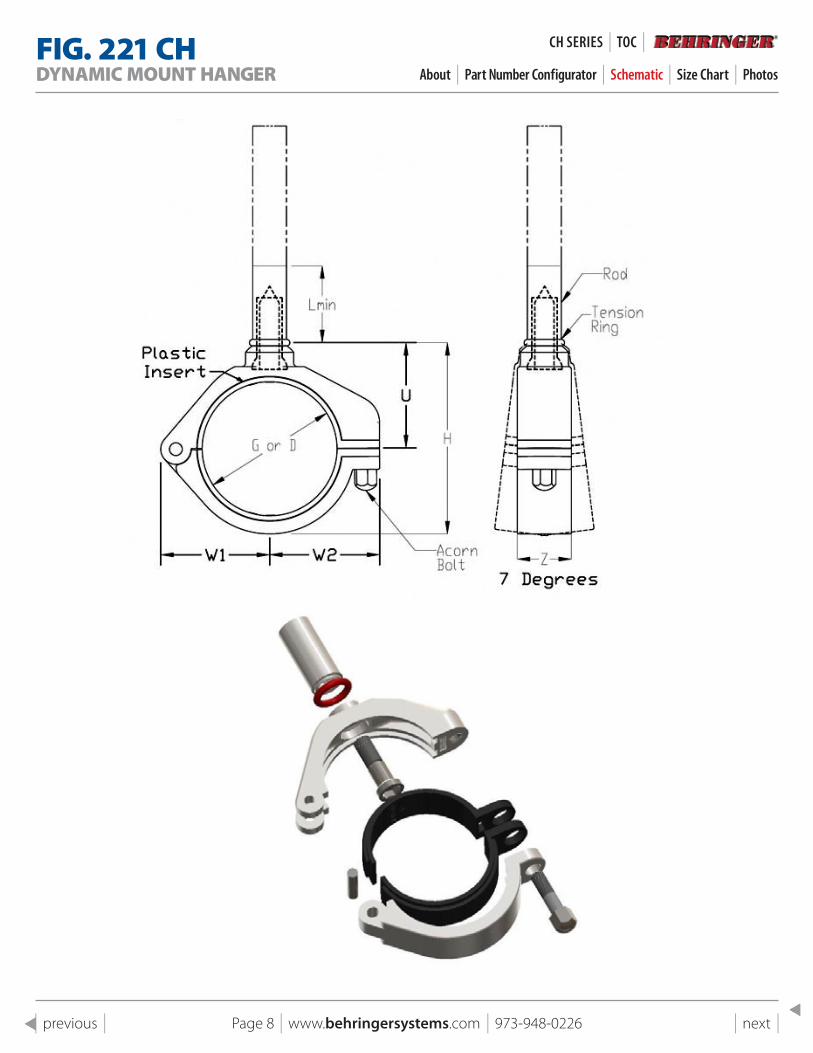
FIG . 221 CHDYNAMIC MOUNT HANGER About | Part Number Configurator | Schematic | Size Chart | Photos
Page 8 | www.behringersystems.com | 973-948-0226 | next | | previous |
CH SeRIeS | TOC |

FIG . 221 CHDYNAMIC MOUNT HANGER About | Part Number Configurator | Schematic | Size Chart | Photos
Gro
up N
o.
Sta
inle
ss T
ube
Pip
e
Cop
per
Tube
Out
side
Dia
met
er (m
m)
221 CHUNIVERSAL DIMENSIONS
AMONG HOUSINGS221 CH
Part Number (-PS- as displayed
is an Anchor & -PG- would make
a Guide) “D"
Anc
hor
Pla
stic
“G"
Gui
de
Pla
stic
Dimension, in. (mm)
Wei
ght,
lb (k
g)
W1 W2 Z L, min U H
Rod
D
iam
eter
1
6 mm 6.0 CH-PS-024-T-?? 0.24 0.27
0.93 (24)
1.02 (26)
0.75 (19)
1.26 (32)
0.95 (24)
1.54 (39)
0.63 (16)
0.76 (0.34)
1/4" 6.3 CH-PS-025-T-?? 0.25 0.29
3/8" 9.6 CH-PS-038-T-?? 0.38 0.40
1/2" 12.7 CH-PS-050-T-?? 0.50 0.54
2
1/4" 13.7 CH-PS-054-T-?? 0.54 0.581.06 (27)
1.15 (29)
0.75 (19)
1.26 (32)
1.07 (27)
1.77 (45)
0.63 (16)
0.79 (0.36)
1/2" 16.0 CH-PS-063-T-?? 0.63 0.67
3/4" 19.0 CH-PS-075-T-?? 0.75 0.79
3
20 mm 20.0 CH-PS-079-T-?? 0.79 0.82
1.20 (31)
1.28 (33)
0.75 (19)
1.26 (32)
1.20 (30)
2.04 (52)
0.63 (16)
0.82 (0.37)
1/2" 21.3 CH-PS-084-T-?? 0.84 0.88
3/4" 22.4 CH-PS-088-T-?? 0.88 0.91
1" 25.4 CH-PS-100-T-?? 1.00 1.04
4
3/4" 26.7 CH-PS-105-T-?? 1.05 1.09
1.45 (37)
1.56 (40)
0.75 (19)
1.26 (32)
1.45 (39)
2.53 (65)
0.63 (16)
0.86 (0.39)
1" 28.7 CH-PS-113-T-?? 1.13 1.16
1" 33.5 CH-PS-132-T-?? 1.32 1.35
1 1/2" 38.1 CH-PS-150-T-?? 1.50 1.54
5
40 mm 40.0 CH-PS-158-T-?? 1.58 1.61
1.74 (44)
1.79 (46)
0.75 (19)
1.26 (32)
1.70 (43)
3.03 (77)
0.63 (16)
0.97 (0.44)
1 1/2" 41.4 CH-PS-163-T-?? 1.63 1.66
1 1/2" 48.3 CH-PS-190-T-?? 1.90 1.94
2" 50.8 CH-PS-200-T-?? 2.00 2.04
6
52 mm 52.0 CH-PS-205-T-?? 2.05 2.10
2.02 (51)
2.04 (52)
1.00 (25)
1.36 (35)
2.04 (52)
3.63 (92)
0.75 (19)
1.37 (0.62)
2" 54.0 CH-PS-213-T-?? 2.13 2.18
2" 60.3 CH-PS-238-T-?? 2.38 2.43
2 1/2" 63.5 CH-PS-250-T-?? 2.50 2.55
7
70 mm 70.0 CH-PS-276-T-?? 2.76 2.812.27 (58)
2.29 (58)
1.00 (25)
1.36 (35)
2.29 (58)
4.13 (105)
0.75 (19)
1.42 (0.64)
2 1/2" 73.1 CH-PS-288-T-?? 2.88 2.93
3" 76.1 CH-PS-300-T-?? 3.00 3.05
8
3" 79.5 CH-PS-313-T-?? 3.13 3.182.76 (70)
2.79 (71)
1.00 (25)
1.36 (35)
2.79 (71)
5.13 (131)
0.75 (19)
1.62 (0.73)
3" 88.9 CH-PS-350-T-?? 3.50 3.55
4" 101.6 CH-PS-400-T-?? 4.00 4.05
8A
104 mm 104.0 CH-PS-409-T-?? 4.09 4.143.00 (76)
3.09 (78)
1.00 (25)
1.36 (35)
3.04 (77)
5.63 (143)
0.75 (19)
1.72 (0.78)
4" 104.9 CH-PS-413-T-?? 4.13 4.18
4" 114.3 CH-PS-450-T-?? 4.50 4.55
9129 mm 129.0 CH-PS-508-T-?? 5.08 5.13 3.98
(101)4.46 (113)
1.50 (38)
1.78 (45)
4.16 (106)
7.74 (197)
1.00 (25)
5.33 (2.42)6" 152.4 CH-PS-600-T-?? 6.00 6.05
Page 9 | www.behringersystems.com | 973-948-0226 | next | | previous |
CH SeRIeS | TOC |
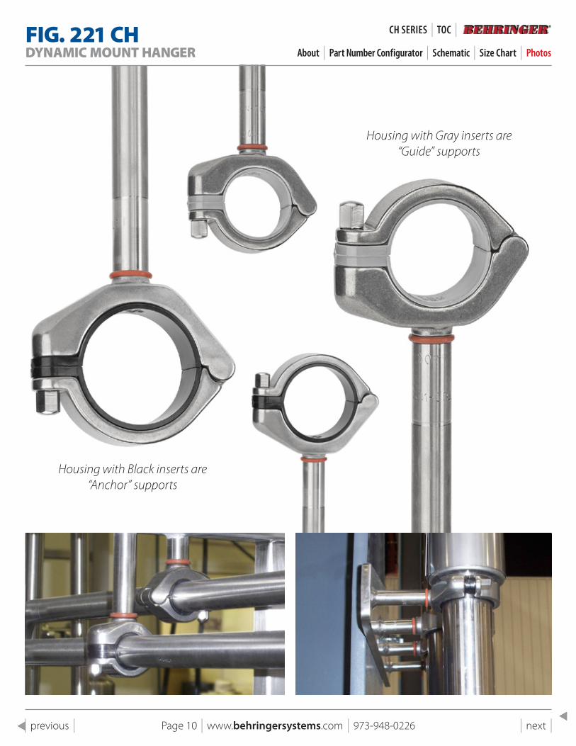
FIG . 221 CHDYNAMIC MOUNT HANGER About | Part Number Configurator | Schematic | Size Chart | Photos
Housing with Gray inserts are “Guide” supports
Housing with Black inserts are “Anchor” supports
Page 10 | www.behringersystems.com | 973-948-0226 | next | | previous |
CH SeRIeS | TOC |
Page 11 | www.behringersystems.com | 973-948-0226 | next | | previous |
FIG . 221 CHRRIGID MOUNT HANGER About | Part Number Configurator | Schematic | Size Chart | Photos
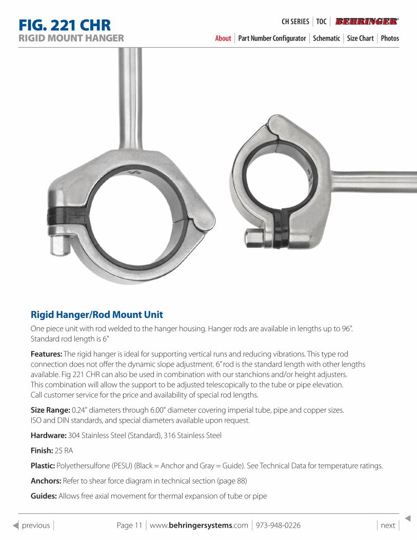
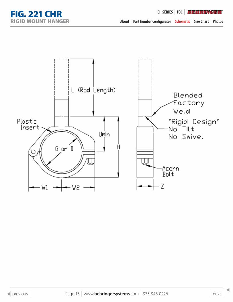
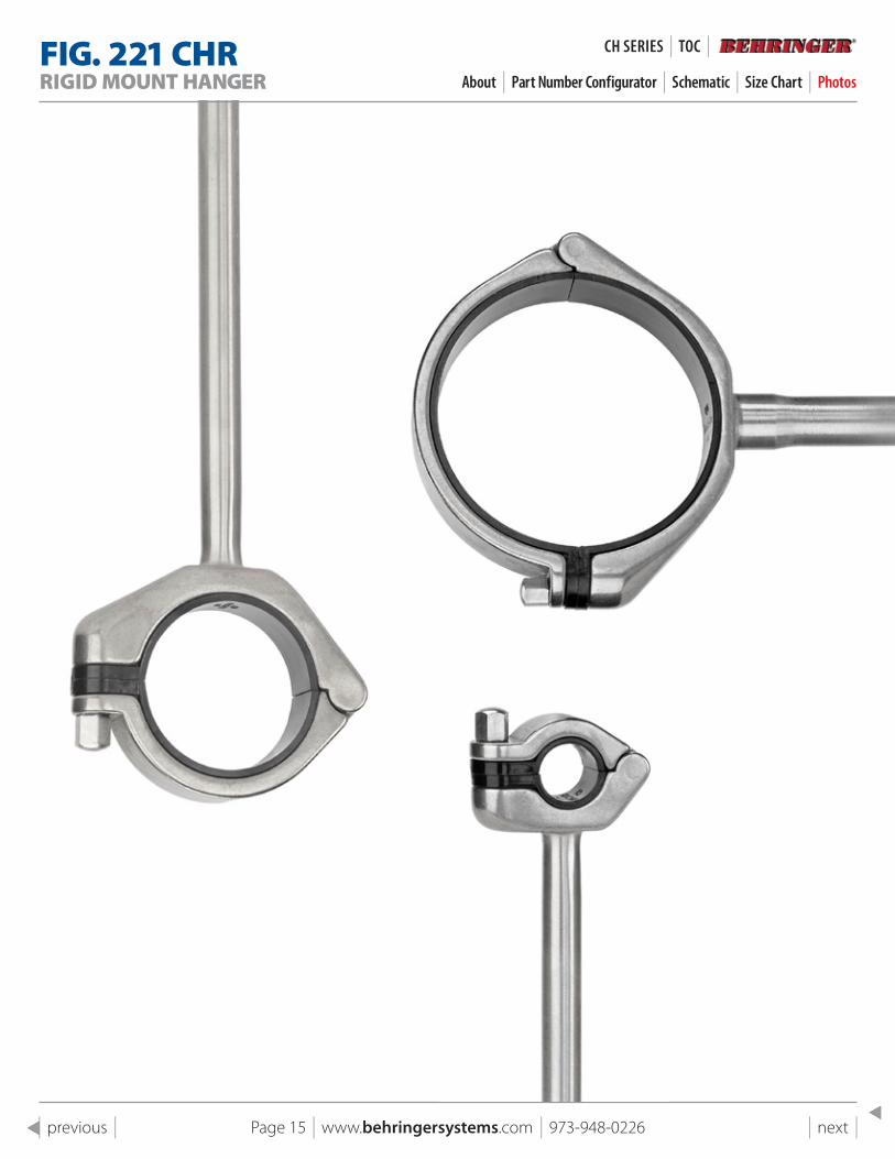
Rigid Hanger/Rod Mount UnitOne piece unit with rod welded to the hanger housing. Hanger rods are available in lengths up to 96". Standard rod length is 6"
Features: The rigid hanger is ideal for supporting vertical runs and reducing vibrations. This type rod connection does not offer the dynamic slope adjustment. 6” rod is the standard length with other lengths available. Fig 221 CHR can also be used in combination with our stanchions and/or height adjusters. This combination will allow the support to be adjusted telescopically to the tube or pipe elevation. Call customer service for the price and availability of special rod lengths.
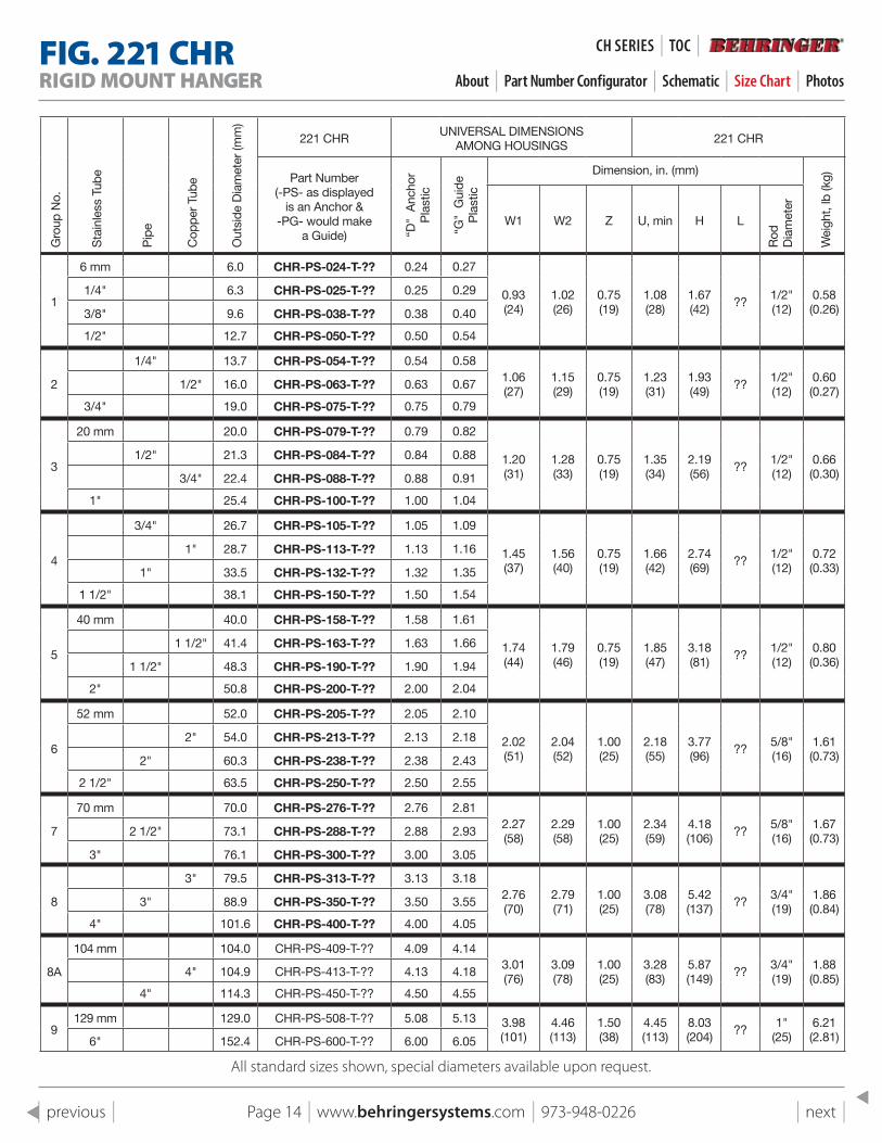
Size Range: 0.24" diameters through 6.00" diameter covering imperial tube, pipe and copper sizes. ISO and DIN standards, and special diameters available upon request.
Hardware: 304 Stainless Steel (Standard), 316 Stainless Steel
Finish: 25 RA
Plastic: Polyethersulfone (PESU) (Black = Anchor and Gray = Guide). See Technical Data for temperature ratings.
Anchors: Refer to shear force diagram in technical section (page 88)
Guides: Allows free axial movement for thermal expansion of tube or pipe
CH SeRIeS | TOC |
Page 12 | www.behringersystems.com | 973-948-0226 | next | | previous |
FIG . 221 CHRRIGID MOUNT HANGER About | Part Number Configurator | Schematic | Size Chart | Photos
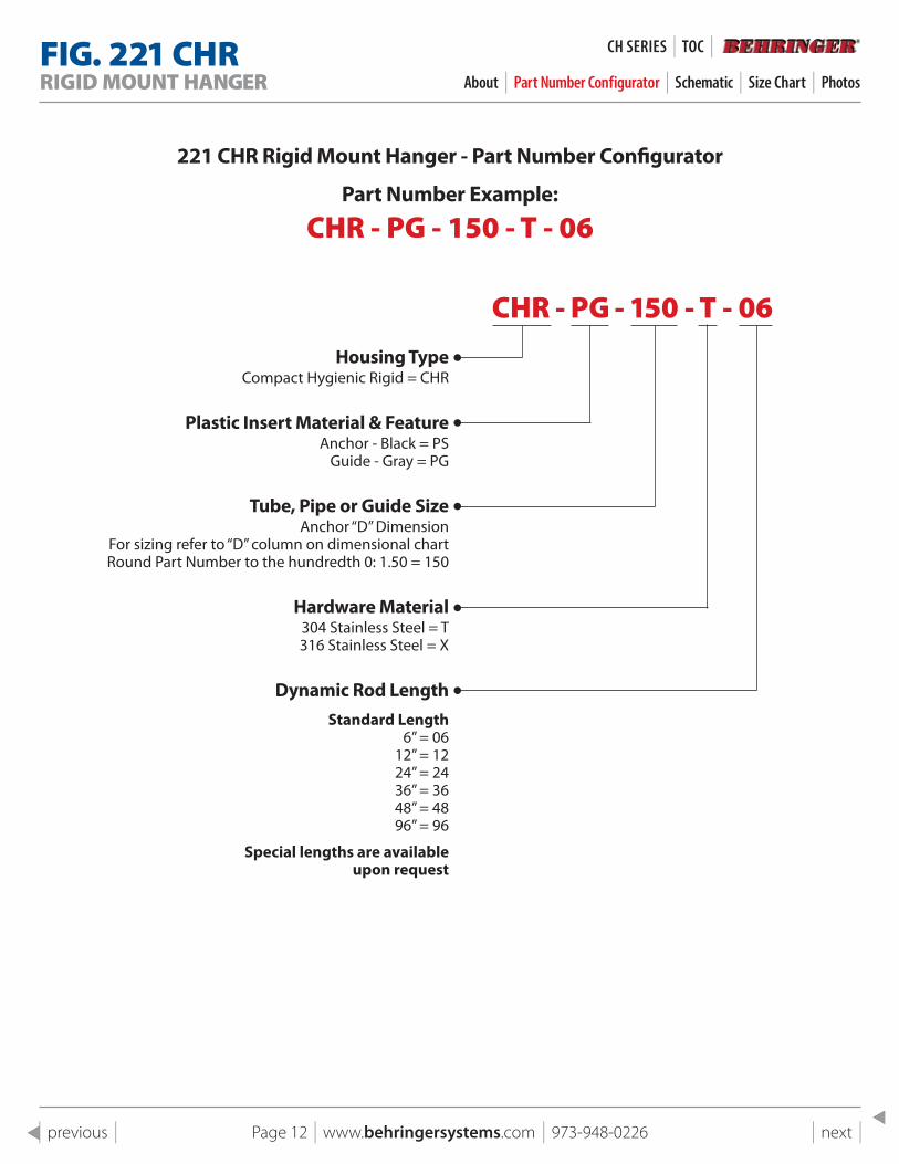
221 CHR Rigid Mount Hanger - part Number Configurator
part Number Example:
CHR - PG - 150 - T - 06
CHR - PG - 150 - T - 06Housing Type
Compact Hygienic Rigid = CHR
plastic Insert Material & FeatureAnchor - Black = PS
Guide - Gray = PG
Tube, pipe or Guide sizeAnchor “D” Dimension
For sizing refer to “D” column on dimensional chartRound Part Number to the hundredth 0: 1.50 = 150
Hardware Material304 Stainless Steel = T 316 Stainless Steel = X
Dynamic Rod lengthstandard length
6” = 0612” = 1224” = 2436” = 3648” = 4896” = 96
special lengths are availableupon request
CH SeRIeS | TOC |
Page 13 | www.behringersystems.com | 973-948-0226 | next | | previous |
FIG . 221 CHRRIGID MOUNT HANGER About | Part Number Configurator | Schematic | Size Chart | Photos
CH SeRIeS | TOC |
Page 14 | www.behringersystems.com | 973-948-0226 | next | | previous |
FIG . 221 CHRRIGID MOUNT HANGER About | Part Number Configurator | Schematic | Size Chart | Photos
Gro
up N
o.
Sta
inle
ss T
ube
Pip
e
Cop
per
Tub
e
Out
side
Dia
met
er (m
m)
221 CHRUNIVERSAL DIMENSIONS
AMONG HOUSINGS221 CHR
Part Number (-PS- as displayed
is an Anchor & -PG- would make
a Guide) “D"
Anc
hor
Pla
stic
“G"
Gui
de
Pla
stic
Dimension, in. (mm)
Wei
ght,
lb (k
g)
W1 W2 Z U, min H L
Rod
D
iam
eter
1
6 mm 6.0 CHR-PS-024-T-?? 0.24 0.27
0.93 (24)
1.02 (26)
0.75 (19)
1.08 (28)
1.67 (42)
??1/2" (12)
0.58 (0.26)
1/4" 6.3 CHR-PS-025-T-?? 0.25 0.29
3/8" 9.6 CHR-PS-038-T-?? 0.38 0.40
1/2" 12.7 CHR-PS-050-T-?? 0.50 0.54
2
1/4" 13.7 CHR-PS-054-T-?? 0.54 0.581.06 (27)
1.15 (29)
0.75 (19)
1.23 (31)
1.93 (49)
??1/2" (12)
0.60 (0.27)
1/2" 16.0 CHR-PS-063-T-?? 0.63 0.67
3/4" 19.0 CHR-PS-075-T-?? 0.75 0.79
3
20 mm 20.0 CHR-PS-079-T-?? 0.79 0.82
1.20 (31)
1.28 (33)
0.75 (19)
1.35 (34)
2.19 (56)
??1/2" (12)
0.66 (0.30)
1/2" 21.3 CHR-PS-084-T-?? 0.84 0.88
3/4" 22.4 CHR-PS-088-T-?? 0.88 0.91
1" 25.4 CHR-PS-100-T-?? 1.00 1.04
4
3/4" 26.7 CHR-PS-105-T-?? 1.05 1.09
1.45 (37)
1.56 (40)
0.75 (19)
1.66 (42)
2.74 (69)
??1/2" (12)
0.72 (0.33)
1" 28.7 CHR-PS-113-T-?? 1.13 1.16
1" 33.5 CHR-PS-132-T-?? 1.32 1.35
1 1/2" 38.1 CHR-PS-150-T-?? 1.50 1.54
5
40 mm 40.0 CHR-PS-158-T-?? 1.58 1.61
1.74 (44)
1.79 (46)
0.75 (19)
1.85 (47)
3.18 (81)
??1/2" (12)
0.80 (0.36)
1 1/2" 41.4 CHR-PS-163-T-?? 1.63 1.66
1 1/2" 48.3 CHR-PS-190-T-?? 1.90 1.94
2" 50.8 CHR-PS-200-T-?? 2.00 2.04
6
52 mm 52.0 CHR-PS-205-T-?? 2.05 2.10
2.02 (51)
2.04 (52)
1.00 (25)
2.18 (55)
3.77 (96)
??5/8" (16)
1.61 (0.73)
2" 54.0 CHR-PS-213-T-?? 2.13 2.18
2" 60.3 CHR-PS-238-T-?? 2.38 2.43
2 1/2" 63.5 CHR-PS-250-T-?? 2.50 2.55
7
70 mm 70.0 CHR-PS-276-T-?? 2.76 2.812.27 (58)
2.29 (58)
1.00 (25)
2.34 (59)
4.18 (106)
??5/8" (16)
1.67 (0.73)
2 1/2" 73.1 CHR-PS-288-T-?? 2.88 2.93
3" 76.1 CHR-PS-300-T-?? 3.00 3.05
8
3" 79.5 CHR-PS-313-T-?? 3.13 3.182.76 (70)
2.79 (71)
1.00 (25)
3.08 (78)
5.42 (137)
??3/4" (19)
1.86 (0.84)
3" 88.9 CHR-PS-350-T-?? 3.50 3.55
4" 101.6 CHR-PS-400-T-?? 4.00 4.05
8A
104 mm 104.0 CHR-PS-409-T-?? 4.09 4.143.01 (76)
3.09 (78)
1.00 (25)
3.28 (83)
5.87 (149)
??3/4" (19)
1.88 (0.85)
4" 104.9 CHR-PS-413-T-?? 4.13 4.18
4" 114.3 CHR-PS-450-T-?? 4.50 4.55
9129 mm 129.0 CHR-PS-508-T-?? 5.08 5.13 3.98
(101)4.46 (113)
1.50 (38)
4.45 (113)
8.03 (204)
??1"
(25)6.21 (2.81)6" 152.4 CHR-PS-600-T-?? 6.00 6.05
All standard sizes shown, special diameters available upon request.
CH SeRIeS | TOC |
Page 15 | www.behringersystems.com | 973-948-0226 | next | | previous |
FIG . 221 CHRRIGID MOUNT HANGER About | Part Number Configurator | Schematic | Size Chart | Photos
CH SeRIeS | TOC |
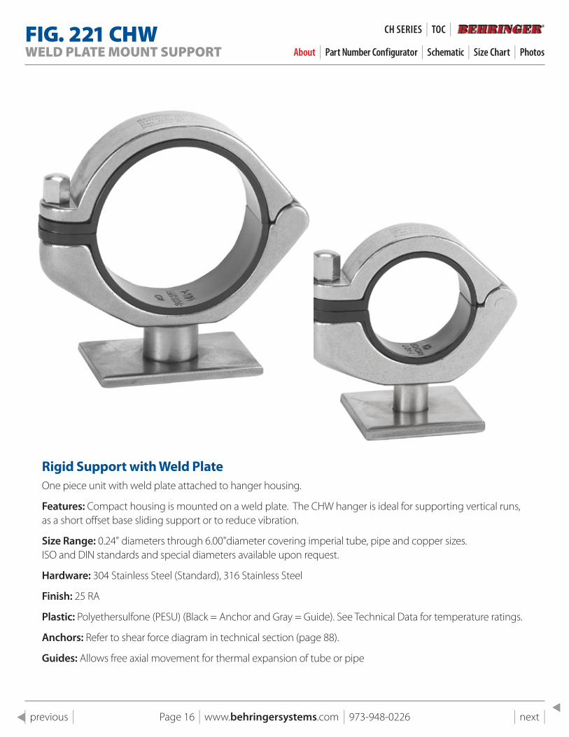
FIG . 221 CHWWELD PLATE MOUNT SUPPORT About | Part Number Configurator | Schematic | Size Chart | Photos
Rigid support with Weld plateOne piece unit with weld plate attached to hanger housing.
Features: Compact housing is mounted on a weld plate. The CHW hanger is ideal for supporting vertical runs, as a short offset base sliding support or to reduce vibration.
Size Range: 0.24" diameters through 6.00"diameter covering imperial tube, pipe and copper sizes. ISO and DIN standards and special diameters available upon request.
Hardware: 304 Stainless Steel (Standard), 316 Stainless Steel
Finish: 25 RA
Plastic: Polyethersulfone (PESU) (Black = Anchor and Gray = Guide). See Technical Data for temperature ratings.
Anchors: Refer to shear force diagram in technical section (page 88).
Guides: Allows free axial movement for thermal expansion of tube or pipe
Page 16 | www.behringersystems.com | 973-948-0226 | next | | previous |
CH SeRIeS | TOC |
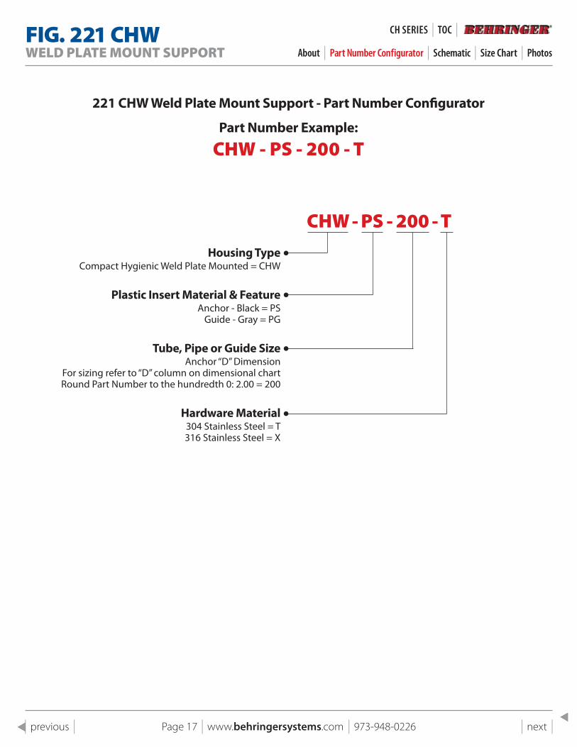
FIG . 221 CHWWELD PLATE MOUNT SUPPORT About | Part Number Configurator | Schematic | Size Chart | Photos
221 CHW Weld plate Mount support - part Number Configurator
part Number Example:
CHW - PS - 200 - T
CHW - PS - 200 - THousing Type
Compact Hygienic Weld Plate Mounted = CHW
plastic Insert Material & FeatureAnchor - Black = PS
Guide - Gray = PG
Tube, pipe or Guide sizeAnchor “D” Dimension
For sizing refer to “D” column on dimensional chartRound Part Number to the hundredth 0: 2.00 = 200
Hardware Material304 Stainless Steel = T 316 Stainless Steel = X
Page 17 | www.behringersystems.com | 973-948-0226 | next | | previous |
CH SeRIeS | TOC |
FIG . 221 CHWWELD PLATE MOUNT SUPPORT About | Part Number Configurator | Schematic | Size Chart | Photos
Page 18 | www.behringersystems.com | 973-948-0226 | next | | previous |
CH SeRIeS | TOC |
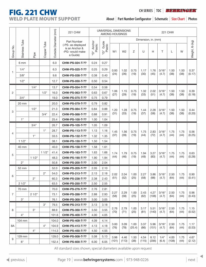
FIG . 221 CHWWELD PLATE MOUNT SUPPORT About | Part Number Configurator | Schematic | Size Chart | Photos
All standard sizes shown, special diameters available upon request
Gro
up N
o.
Sta
inle
ss T
ube
Pip
e
Cop
per
Tube
Out
side
Dia
met
er (m
m)
221 CHWUNIVERSAL DIMENSIONS
AMONG HOUSINGS221 CHW
Part Number (-PS- as displayed
is an Anchor & -PG- would make
a Guide) “D"
Anc
hor
Pla
stic
“G"
Gui
de
Pla
stic
Dimension, in. (mm)
Wei
ght,
lb (k
g)
W1 W2 Z U H T L W
1
6 mm 6.0 CHW-PS-024-T-?? 0.24 0.27
0.93 (24)
1.02 (26)
0.75 (19)
1.17 (30)
1.76 (45)
3/16" (4.7)
1.50 (38)
1.50 (38)
0.37 (0.17)
1/4" 6.3 CHW-PS-025-T-?? 0.25 0.29
3/8" 9.6 CHW-PS-038-T-?? 0.38 0.40
1/2" 12.7 CHW-PS-050-T-?? 0.50 0.54
2
1/4" 13.7 CHW-PS-054-T-?? 0.54 0.581.06 (27)
1.15 (29)
0.75 (19)
1.32 (33)
2.02 (51)
3/16" (4.7)
1.50 (38)
1.50 (38)
0.39 (0.18)
1/2" 16.0 CHW-PS-063-T-?? 0.63 0.67
3/4" 19.0 CHW-PS-075-T-?? 0.75 0.79
3
20 mm 20.0 CHW-PS-079-T-?? 0.79 0.82
1.20 (31)
1.28 (33)
0.75 (19)
1.44 (37)
2.28 (58)
3/16" (4.7)
1.50 (38)
1.50 (38)
0.44 (0.20)
1/2" 21.3 CHW-PS-084-T-?? 0.84 0.88
3/4" 22.4 CHW-PS-088-T-?? 0.88 0.91
1" 25.4 CHW-PS-100-T-?? 1.00 1.04
4
3/4" 26.7 CHW-PS-105-T-?? 1.05 1.09
1.45 (37)
1.56 (39)
0.75 (19)
1.75 (44)
2.83 (72)
3/16" (4.7)
1.75 (44)
1.75 (44)
0.56 (0.25)
1" 28.7 CHW-PS-113-T-?? 1.13 1.16
1" 33.5 CHW-PS-132-T-?? 1.32 1.35
1 1/2" 38.1 CHW-PS-150-T-?? 1.50 1.54
5
40 mm 40.0 CHW-PS-158-T-?? 1.58 1.61
1.74 (44)
1.79 (46)
0.75 (19)
1.94 (49)
3.27 (83)
3/16" (4.7)
1.75 (44)
1.75 (44)
0.63 (0.28)
1 1/2" 41.4 CHW-PS-163-T-?? 1.63 1.66
1 1/2" 48.3 CHW-PS-190-T-?? 1.90 1.94
2" 50.8 CHW-PS-200-T-?? 2.00 2.04
6
52 mm 52.0 CHW-PS-205-T-?? 2.05 2.10
2.02 (51)
2.04 (52)
1.00 (25)
2.27 (58)
3.86 (98)
3/16" (4.7)
2.50 (64)
1.75 (44)
0.90 (0.41)
2" 54.0 CHW-PS-213-T-?? 2.13 2.18
2" 60.3 CHW-PS-238-T-?? 2.38 2.43
2 1/2" 63.5 CHW-PS-250-T-?? 2.50 2.55
7
70 mm 70.0 CHW-PS-276-T-?? 2.76 2.812.27 (58)
2.29 (58)
1.00 (25)
2.43 (62)
4.27 (108)
3/16" (4.7)
2.50 (64)
1.75 (44)
0.96 (0.43)
2 1/2" 73.1 CHW-PS-288-T-?? 2.88 2.93
3" 76.1 CHW-PS-300-T-?? 3.00 3.05
8
3" 79.5 CHW-PS-313-T-?? 3.13 3.182.76 (70)
2.79 (71)
1.00 (25)
3.17 (81)
5.51 (140)
3/16" (4.7)
2.50 (64)
1.75 (44)
1.15 (0.52)
3" 88.9 CHW-PS-350-T-?? 3.50 3.55
4" 101.6 CHW-PS-400-T-?? 4.00 4.05
8A
104 mm 104.0 CHW-PS-409-T-?? 4.09 4.143.00 (76)
3.09 (78)
1.00 (25.4)
3.37 (86)
5.96 (151)
3/16" (4.7)
2.50 (64)
1.75 (44)
1.17 (0.53)
4" 104.9 CHW-PS-413-T-?? 4.13 4.18
4" 114.3 CHW-PS-450-T-?? 4.50 4.55
9129 mm 129.0 CHW-PS-508-T-?? 5.08 5.13 3.98
(101)4.46 (113)
1.50 (38)
4.54 (115)
8.12 (206)
1/4" (6.4)
4.00 (108)
1.75 (44)
4.67 (2.12)6" 152.4 CHW-PS-600-T-?? 6.00 6.05
Page 19 | www.behringersystems.com | 973-948-0226 | next | | previous |
CH SeRIeS | TOC |
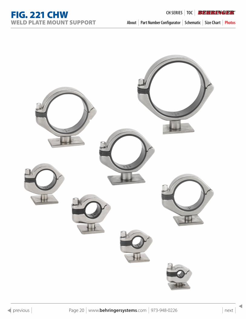
FIG . 221 CHWWELD PLATE MOUNT SUPPORT About | Part Number Configurator | Schematic | Size Chart | Photos
Page 20 | www.behringersystems.com | 973-948-0226 | next | | previous |
CH SeRIeS | TOC |
Page 21 | www.behringersystems.com | 973-948-0226 | next | | previous |
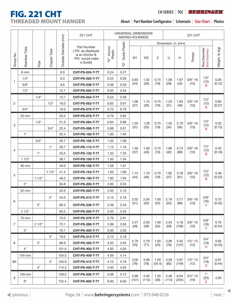
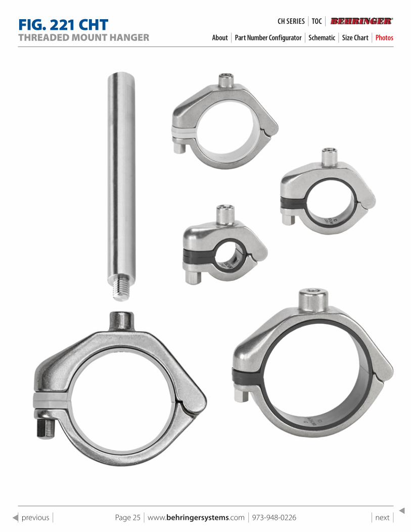
FIG . 221 CHTTHREADED MOUNT HANGER About | Part Number Configurator | Schematic | Size Chart | Photos
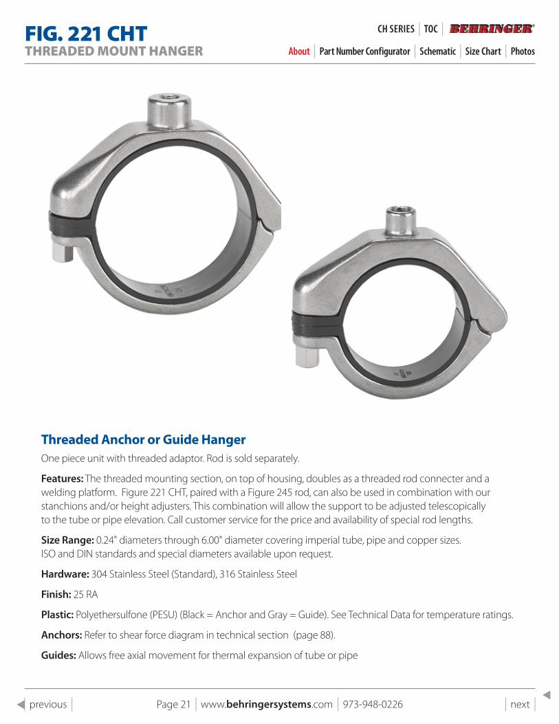
Threaded Anchor or Guide HangerOne piece unit with threaded adaptor. Rod is sold separately.
Features: The threaded mounting section, on top of housing, doubles as a threaded rod connecter and a welding platform. Figure 221 CHT, paired with a Figure 245 rod, can also be used in combination with our stanchions and/or height adjusters. This combination will allow the support to be adjusted telescopically to the tube or pipe elevation. Call customer service for the price and availability of special rod lengths.
Size Range: 0.24" diameters through 6.00" diameter covering imperial tube, pipe and copper sizes.ISO and DIN standards and special diameters available upon request.
Hardware: 304 Stainless Steel (Standard), 316 Stainless Steel
Finish: 25 RA
Plastic: Polyethersulfone (PESU) (Black = Anchor and Gray = Guide). See Technical Data for temperature ratings.
Anchors: Refer to shear force diagram in technical section (page 88).
Guides: Allows free axial movement for thermal expansion of tube or pipe
CH SeRIeS | TOC |
Page 22 | www.behringersystems.com | 973-948-0226 | next | | previous |
FIG . 221 CHTTHREADED MOUNT HANGER About | Part Number Configurator | Schematic | Size Chart | Photos
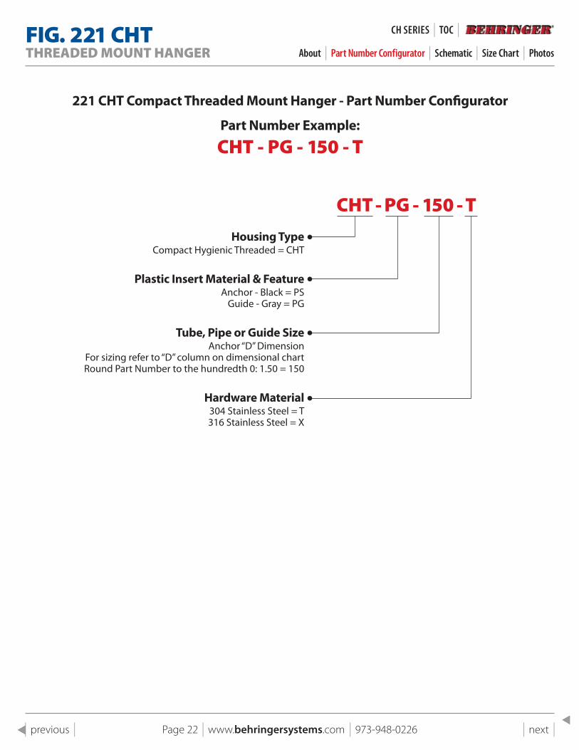
221 CHT Compact Threaded Mount Hanger - part Number Configurator
part Number Example:
CHT - PG - 150 - T
CHT - PG - 150 - THousing Type
Compact Hygienic Threaded = CHT
plastic Insert Material & FeatureAnchor - Black = PS
Guide - Gray = PG
Tube, pipe or Guide sizeAnchor “D” Dimension
For sizing refer to “D” column on dimensional chartRound Part Number to the hundredth 0: 1.50 = 150
Hardware Material304 Stainless Steel = T 316 Stainless Steel = X
CH SeRIeS | TOC |
Page 23 | www.behringersystems.com | 973-948-0226 | next | | previous |
FIG . 221 CHTTHREADED MOUNT HANGER About | Part Number Configurator | Schematic | Size Chart | Photos
CH SeRIeS | TOC |
Page 24 | www.behringersystems.com | 973-948-0226 | next | | previous |
FIG . 221 CHTTHREADED MOUNT HANGER About | Part Number Configurator | Schematic | Size Chart | Photos
Gro
up N
o.
Sta
inle
ss T
ube
Pip
e
Cop
per
Tube
Out
side
Dia
met
er (m
m) 221 CHT
UNIVERSAL DIMENSIONS AMONG HOUSINGS
221 CHT
Part Number (-PS- as displayed
is an Anchor & -PG- would make
a Guide) “D"
Anc
hor
Pla
stic
“G"
Gui
de P
last
ic Dimension, in. (mm)
Wei
ght,
lb (k
g)
W1 W2 Z U H
Thre
ad
Rod
Dia
met
er
(Sol
d S
epar
tely
)
1
6 mm 6.0 CHT-PS-024-T-?? 0.24 0.27
0.93 (24)
1.02 (26)
0.75 (19)
1.08 (28)
1.67 (42)
3/8"-16 (10)
1/2" (12) B
0.26 (0.12)
1/4" 6.3 CHT-PS-025-T-?? 0.25 0.29
3/8" 9.6 CHT-PS-038-T-?? 0.38 0.40
1/2" 12.7 CHT-PS-050-T-?? 0.50 0.54
2
1/4" 13.7 CHT-PS-054-T-?? 0.54 0.581.06 (27)
1.15 (29)
0.75 (19)
1.23 (31)
1.93 (49)
3/8"-16 (10)
1/2" (12)B
0.60 (0.27)
1/2" 16.0 CHT-PS-063-T-?? 0.63 0.67
3/4" 19.0 CHT-PS-075-T-?? 0.75 0.79
3
20 mm 20.0 CHT-PS-079-T-?? 0.79 0.82
1.20 (31)
1.28 (33)
0.75 (19)
1.35 (34)
2.19 (56)
3/8"-16 (10)
1/2" (12) B
0.33 (0.15)
1/2" 21.3 CHT-PS-084-T-?? 0.84 0.88
3/4" 22.4 CHT-PS-088-T-?? 0.88 0.91
1" 25.4 CHT-PS-100-T-?? 1.00 1.04
4
3/4" 26.7 CHT-PS-105-T-?? 1.05 1.09
1.46 (37)
1.56 (40)
0.75 (19)
1.66 (42)
2.74 (69)
3/8"-16 (10)
1/2" (12) B
0.40 (0.18)
1" 28.7 CHT-PS-113-T-?? 1.13 1.16
1" 33.5 CHT-PS-132-T-?? 1.32 1.35
1 1/2" 38.1 CHT-PS-150-T-?? 1.50 1.54
5
40 mm 40.0 CHT-PS-158-T-?? 1.58 1.61
1.74 (44)
1.79 (46)
0.75 (19)
1.85 (47)
3.18 (81)
3/8"-16 (10)
1/2" (12) B
0.48 (0.22)
1 1/2" 41.4 CHT-PS-163-T-?? 1.63 1.66
1 1/2" 48.3 CHT-PS-190-T-?? 1.90 1.94
2" 50.8 CHT-PS-200-T-?? 2.00 2.04
6
52 mm 52.0 CHT-PS-205-T-?? 2.05 2.10
2.02 (51)
2.04 (52)
1.00 (25)
2.18 (55)
3.77 (96)
3/8"-16 (10)
5/8" (16) C
0.70 (0.32)
2" 54.0 CHT-PS-213-T-?? 2.13 2.18
2" 60.3 CHT-PS-238-T-?? 2.38 2.43
2 1/2" 63.5 CHT-PS-250-T-?? 2.50 2.55
7
70 mm 70.0 CHT-PS-276-T-?? 2.76 2.812.27 (58)
2.29 (58)
1.00 (25)
2.34 (59)
4.18 (106)
3/8"-16 (10)
5/8" (16) C
0.76 (0.34)
2 1/2" 73.1 CHT-PS-288-T-?? 2.88 2.93
3" 76.1 CHT-PS-300-T-?? 3.00 3.05
8
3" 79.5 CHT-PS-313-T-?? 3.13 3.182.76 (70)
2.79 (71)
1.00 (25)
3.08 (78)
5.42 (137)
1/2"-13 (12)
3/4" (19) D
0.95 (0.43)
3" 88.9 CHT-PS-350-T-?? 3.50 3.55
4" 101.6 CHT-PS-400-T-?? 4.00 4.05
8A
104 mm 104.0 CHT-PS-409-T-?? 4.09 4.143.00 (76)
3.09 (78)
1.00 (25.4)
3.28 (83)
5.87 (149)
1/2"-13 (12)
3/4" (19) D
0.97 (0.44)
4" 104.9 CHT-PS-413-T-?? 4.13 4.18
4" 114.3 CHT-PS-450-T-?? 4.50 4.55
9129 mm 129.0 CHT-PS-508-T-?? 5.08 5.13 3.98
(101)4.46 (113)
1.50 (38)
4.46 (113)
8.04 (204)
3/4"-10 (19)
1" (25) E
4.206" 152.4 CHT-PS-600-T-?? 6.00 6.05
CH SeRIeS | TOC |
Page 25 | www.behringersystems.com | 973-948-0226 | next | | previous |
FIG . 221 CHTTHREADED MOUNT HANGER About | Part Number Configurator | Schematic | Size Chart | Photos
CH SeRIeS | TOC |
Page 26 | www.behringersystems.com | 973-948-0226 | next | | previous |
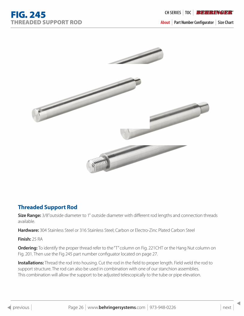
FIG . 245THREADED SUPPORT ROD About | Part Number Configurator | Size Chart
Threaded support RodSize Range: 3/8"outside diameter to 1" outside diameter with different rod lengths and connection threads available.
Hardware: 304 Stainless Steel or 316 Stainless Steel; Carbon or Electro-Zinc Plated Carbon Steel
Finish: 25 RA
Ordering: To identify the proper thread refer to the “T” column on Fig. 221CHT or the Hang Nut column on Fig. 201. Then use the Fig 245 part number configuator located on page 27.
Installations: Thread the rod into housing. Cut the rod in the field to proper length. Field weld the rod to support structure. The rod can also be used in combination with one of our stanchion assemblies. This combination will allow the support to be adjusted telescopically to the tube or pipe elevation.
CH SeRIeS | TOC |
Page 27 | www.behringersystems.com | 973-948-0226 | next | | previous |
FIG . 245THREADED SUPPORT ROD About | Part Number Configurator | Size Chart
CH SeRIeS | TOC |
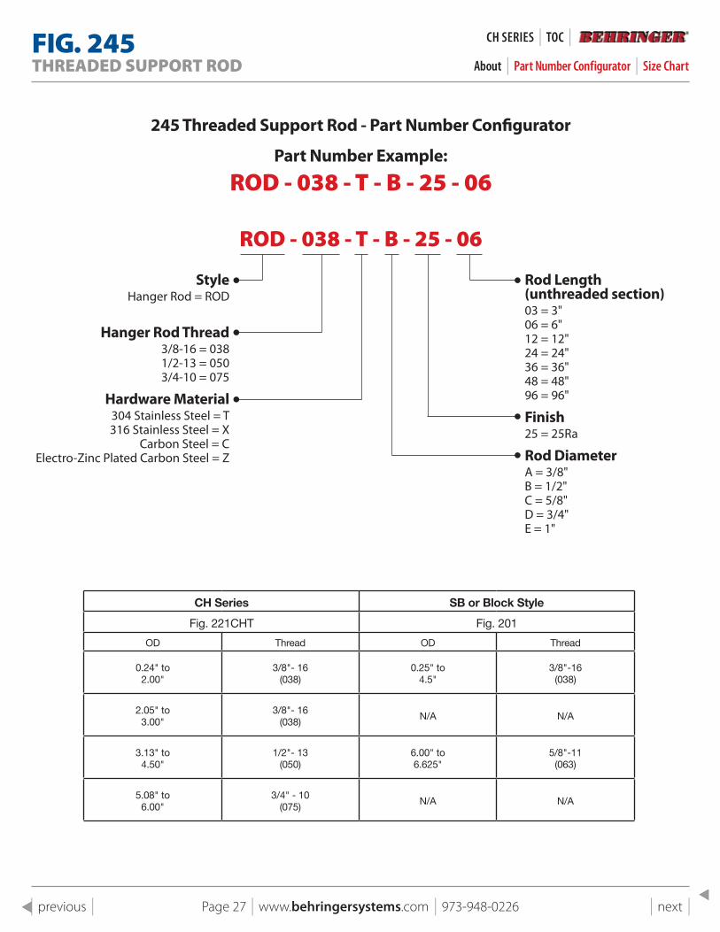
245 Threaded support Rod - part Number Configurator
part Number Example:
ROD - 038 - T - B - 25 - 06
ROD - 038 - T - B - 25 - 06
styleHanger Rod = ROD
Hanger Rod Thread3/8-16 = 0381/2-13 = 0503/4-10 = 075
Hardware Material304 Stainless Steel = T316 Stainless Steel = X
Carbon Steel = CElectro-Zinc Plated Carbon Steel = Z
Rod length (unthreaded section)03 = 3"06 = 6"12 = 12"24 = 24"36 = 36"48 = 48"96 = 96"
Finish25 = 25Ra
Rod DiameterA = 3/8"B = 1/2"C = 5/8"D = 3/4"E = 1"
CH Series SB or Block Style
Fig. 221CHT Fig. 201
OD Thread OD Thread
0.24" to 2.00"
3/8"- 16(038)
0.25" to4.5"
3/8"-16(038)
2.05" to 3.00"
3/8"- 16(038)
N/A N/A
3.13" to 4.50"
1/2"- 13(050)
6.00" to6.625"
5/8"-11(063)
5.08" to 6.00"
3/4" - 10(075)
N/A N/A
Page 28 | www.behringersystems.com | 973-948-0226 | next | | previous |
Tapered GuidesHANGERS & SUPPORTS About | Schematic | Photos
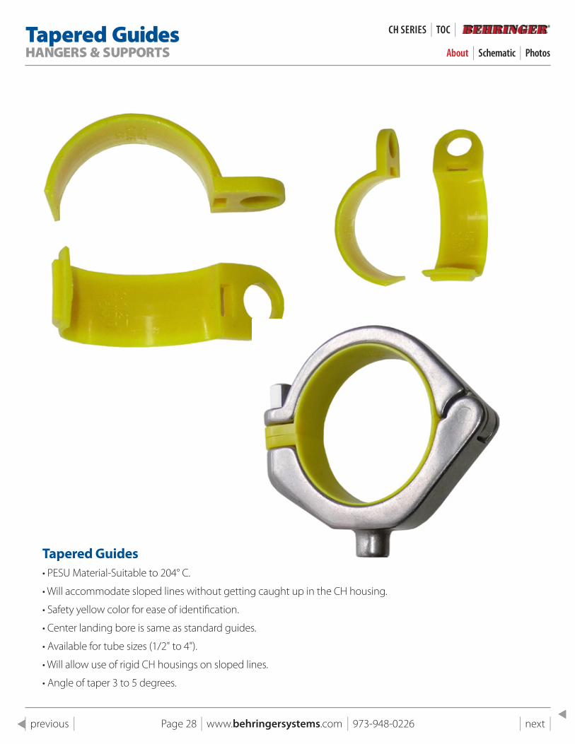
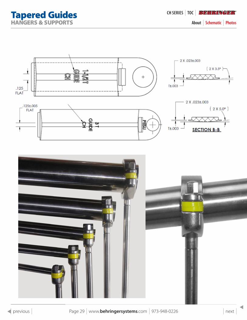
Tapered Guides• PESU Material-Suitable to 204° C.
• Will accommodate sloped lines without getting caught up in the CH housing.
• Safety yellow color for ease of identification.
• Center landing bore is same as standard guides.
• Available for tube sizes (1/2" to 4").
• Will allow use of rigid CH housings on sloped lines.
• Angle of taper 3 to 5 degrees.
CH SeRIeS | TOC |
Page 29 | www.behringersystems.com | 973-948-0226 | next | | previous |
Tapered GuidesHANGERS & SUPPORTS
CH SeRIeS | TOC |
About | Schematic | Photos
Smooth Bore SeriesHANGER & SUPPORTS
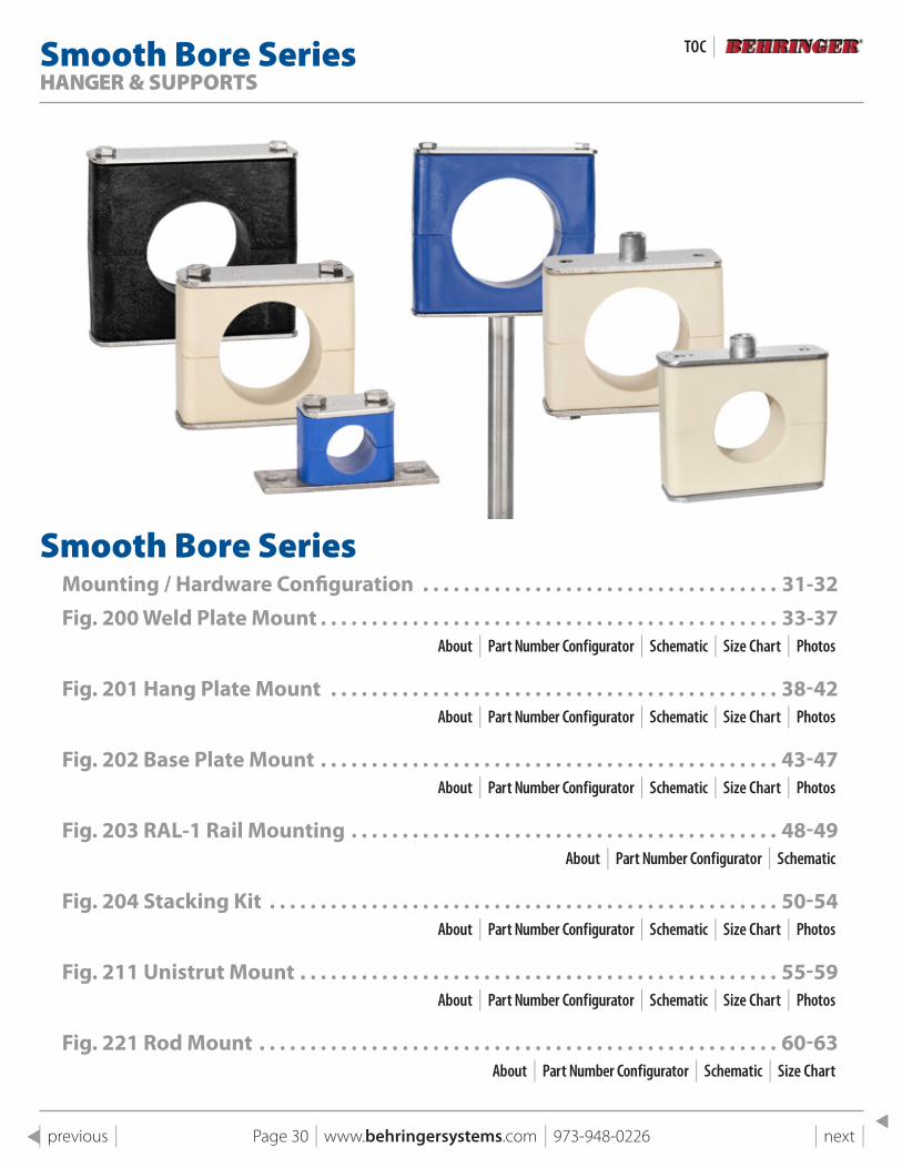
Smooth Bore SeriesMounting / Hardware Configuration . . . . . . . . . . . . . . . . . . . . . . . . . . . . . . . . . . . 31-32Fig . 200 Weld plate Mount . . . . . . . . . . . . . . . . . . . . . . . . . . . . . . . . . . . . . . . . . . . . . 33-37
About | Part Number Configurator | Schematic | Size Chart | Photos
Fig . 201 Hang plate Mount . . . . . . . . . . . . . . . . . . . . . . . . . . . . . . . . . . . . . . . . . . . . 38-42About | Part Number Configurator | Schematic | Size Chart | Photos
Fig . 202 Base plate Mount . . . . . . . . . . . . . . . . . . . . . . . . . . . . . . . . . . . . . . . . . . . . . 43-47About | Part Number Configurator | Schematic | Size Chart | Photos
Fig . 203 RAl-1 Rail Mounting . . . . . . . . . . . . . . . . . . . . . . . . . . . . . . . . . . . . . . . . . . 48-49About | Part Number Configurator | Schematic
Fig . 204 stacking Kit . . . . . . . . . . . . . . . . . . . . . . . . . . . . . . . . . . . . . . . . . . . . . . . . . . 50-54About | Part Number Configurator | Schematic | Size Chart | Photos
Fig . 211 Unistrut Mount . . . . . . . . . . . . . . . . . . . . . . . . . . . . . . . . . . . . . . . . . . . . . . . 55-59About | Part Number Configurator | Schematic | Size Chart | Photos
Fig . 221 Rod Mount . . . . . . . . . . . . . . . . . . . . . . . . . . . . . . . . . . . . . . . . . . . . . . . . . . . 60-63About | Part Number Configurator | Schematic | Size Chart
TOC |
Page 30 | www.behringersystems.com | 973-948-0226 | next | | previous |
Smooth Bore SeriesMOUNTING & HARDWARE CONFIGURATION
SMOOTH BORe SeRIeS | TOC |
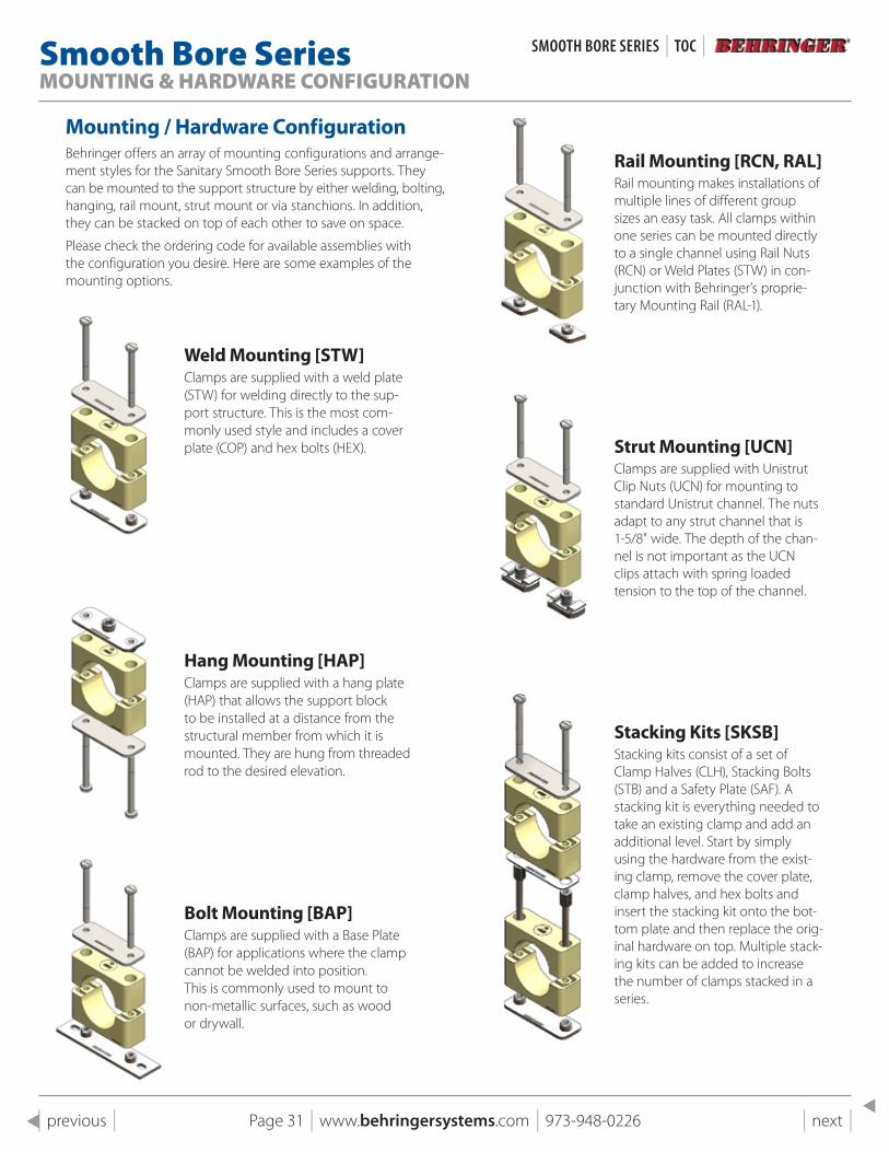
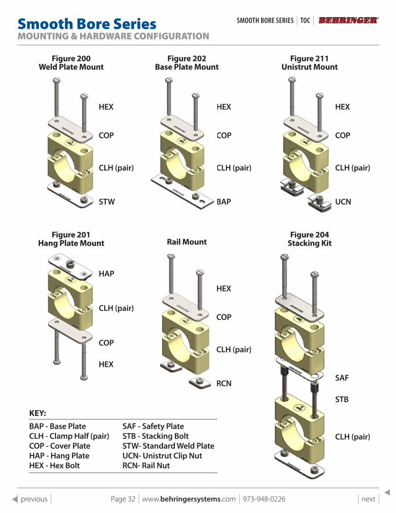
Mounting / Hardware ConfigurationBehringer offers an array of mounting configurations and arrange-ment styles for the Sanitary Smooth Bore Series supports. They can be mounted to the support structure by either welding, bolting, hanging, rail mount, strut mount or via stanchions. In addition, they can be stacked on top of each other to save on space.
Please check the ordering code for available assemblies with the configuration you desire. Here are some examples of the mounting options.
Weld Mounting [sTW]Clamps are supplied with a weld plate (STW) for welding directly to the sup-port structure. This is the most com-monly used style and includes a cover plate (COP) and hex bolts (HEX).
Hang Mounting [HAp]Clamps are supplied with a hang plate (HAP) that allows the support block to be installed at a distance from the structural member from which it is mounted. They are hung from threaded rod to the desired elevation.
Bolt Mounting [BAp]Clamps are supplied with a Base Plate (BAP) for applications where the clamp cannot be welded into position. This is commonly used to mount to non-metallic surfaces, such as wood or drywall.
Rail Mounting [RCN, RAl]Rail mounting makes installations of multiple lines of different group sizes an easy task. All clamps within one series can be mounted directly to a single channel using Rail Nuts (RCN) or Weld Plates (STW) in con-junction with Behringer’s proprie-tary Mounting Rail (RAL-1).
strut Mounting [UCN]Clamps are supplied with Unistrut Clip Nuts (UCN) for mounting to standard Unistrut channel. The nuts adapt to any strut channel that is 1-5/8" wide. The depth of the chan-nel is not important as the UCN clips attach with spring loaded tension to the top of the channel.
stacking Kits [sKsB]Stacking kits consist of a set of Clamp Halves (CLH), Stacking Bolts (STB) and a Safety Plate (SAF). A stacking kit is everything needed to take an existing clamp and add an additional level. Start by simply using the hardware from the exist-ing clamp, remove the cover plate, clamp halves, and hex bolts and insert the stacking kit onto the bot-tom plate and then replace the orig-inal hardware on top. Multiple stack-ing kits can be added to increase the number of clamps stacked in a series.
Page 31 | www.behringersystems.com | 973-948-0226 | next | | previous |
Smooth Bore SeriesMOUNTING & HARDWARE CONFIGURATION
Figure 200 Weld plate Mount
Figure 201 Hang plate Mount
Figure 202 Base plate Mount
Rail Mount
Figure 211 Unistrut Mount
Figure 204 stacking Kit
KEY:
BAP - Base Plate SAF - Safety PlateCLH - Clamp Half (pair) STB - Stacking BoltCOP - Cover Plate STW- Standard Weld PlateHAP - Hang Plate UCN- Unistrut Clip NutHEX - Hex Bolt RCN- Rail Nut
HEX HEX
SAF
HEX
HEX
HEX
COP COP
STB
COP
COP
COP
CLH (pair) CLH (pair)
CLH (pair)
CLH (pair)
CLH (pair)
CLH (pair)
STW UCNBAP
RCN
HAP
Page 32 | www.behringersystems.com | 973-948-0226 | next | | previous |
SMOOTH BORe SeRIeS | TOC |
Page 33 | www.behringersystems.com | 973-948-0226 | next | | previous |
FIG . 200SMOOTH BORE WELD PLATE MOUNT About | Part Number Configurator | Schematic | Size Chart | Photos
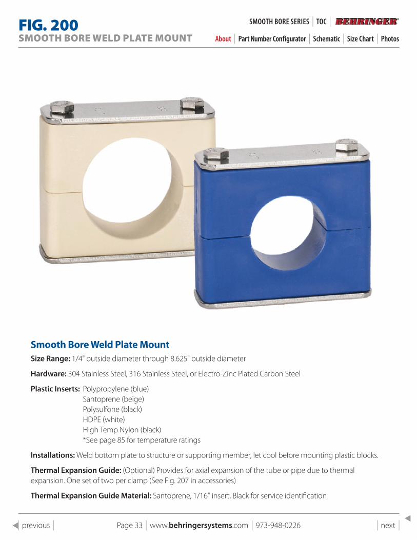
smooth Bore Weld plate MountSize Range: 1/4" outside diameter through 8.625" outside diameter
Hardware: 304 Stainless Steel, 316 Stainless Steel, or Electro-Zinc Plated Carbon Steel
Plastic Inserts: Polypropylene (blue)Santoprene (beige) Polysulfone (black) HDPE (white) High Temp Nylon (black) *See page 85 for temperature ratings
Installations: Weld bottom plate to structure or supporting member, let cool before mounting plastic blocks.
Thermal Expansion Guide: (Optional) Provides for axial expansion of the tube or pipe due to thermal expansion. One set of two per clamp (See Fig. 207 in accessories)
Thermal Expansion Guide Material: Santoprene, 1/16" insert, Black for service identification
SMOOTH BORe SeRIeS | TOC |
Page 34 | www.behringersystems.com | 973-948-0226 | next | | previous |
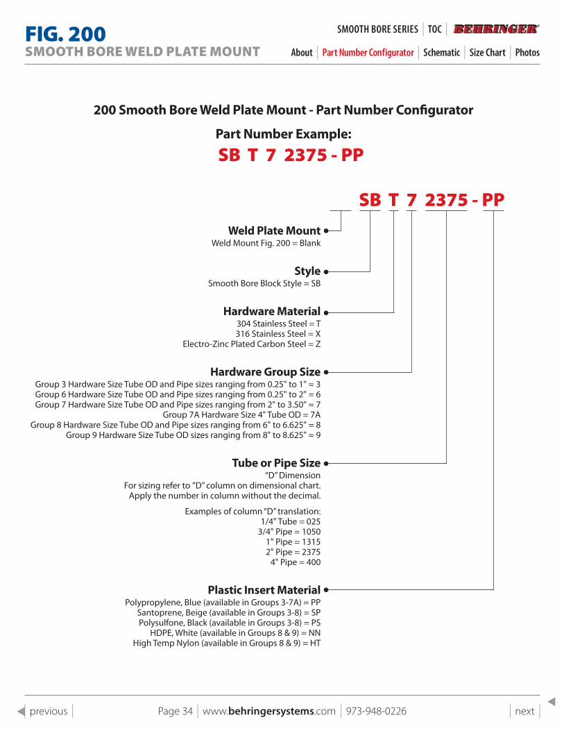
200 smooth Bore Weld plate Mount - part Number Configurator
part Number Example:
SB T 7 2375 - PP
SB T 7 2375 - PPWeld plate Mount
Weld Mount Fig. 200 = Blank
styleSmooth Bore Block Style = SB
Hardware Material304 Stainless Steel = T 316 Stainless Steel = X
Electro-Zinc Plated Carbon Steel = Z
Hardware Group sizeGroup 3 Hardware Size Tube OD and Pipe sizes ranging from 0.25" to 1" = 3 Group 6 Hardware Size Tube OD and Pipe sizes ranging from 0.25" to 2" = 6 Group 7 Hardware Size Tube OD and Pipe sizes ranging from 2" to 3.50" = 7
Group 7A Hardware Size 4" Tube OD = 7AGroup 8 Hardware Size Tube OD and Pipe sizes ranging from 6" to 6.625" = 8
Group 9 Hardware Size Tube OD sizes ranging from 8" to 8.625" = 9
Tube or pipe size“D” Dimension
For sizing refer to ”D” column on dimensional chart.Apply the number in column without the decimal.
Examples of column “D” translation:1/4" Tube = 025
3/4" Pipe = 10501" Pipe = 13152" Pipe = 2375
4" Pipe = 400
plastic Insert Material Polypropylene, Blue (available in Groups 3-7A) = PP
Santoprene, Beige (available in Groups 3-8) = SP Polysulfone, Black (available in Groups 3-8) = PS
HDPE, White (available in Groups 8 & 9) = NN High Temp Nylon (available in Groups 8 & 9) = HT
FIG . 200SMOOTH BORE WELD PLATE MOUNT About | Part Number Configurator | Schematic | Size Chart | Photos
SMOOTH BORe SeRIeS | TOC |
Page 35 | www.behringersystems.com | 973-948-0226 | next | | previous |
1
1
2
2
3
3
4
4
A A
B B
C C
D D
SHEET 1 OF 1
DRAWN
CHECKED
QA
MFG
APPROVED
11/4/2018
DWG NO
200 pg 19 Assembly
TITLE
Fig 200 Weld Plate Block Mount
SIZE
CSCALE
REV
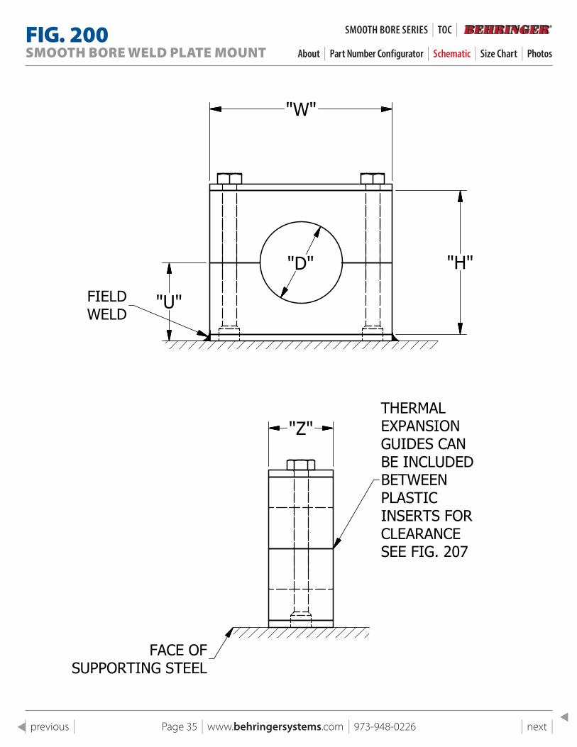
"W"
"H"
"U"FIELDWELD
"D"
"Z"
FACE OFSUPPORTING STEEL
THERMALEXPANSIONGUIDES CANBE INCLUDEDBETWEENPLASTIC INSERTS FORCLEARANCESEE FIG. 207
1
1
2
2
3
3
4
4
A A
B B
C C
D D
SHEET 1 OF 1
DRAWN
CHECKED
QA
MFG
APPROVED
11/4/2018
DWG NO
200 pg 19 Assembly
TITLE
Fig 200 Weld Plate Block Mount
SIZE
CSCALE
REV
"W"
"H"
"U"FIELDWELD
"D"
"Z"
FACE OFSUPPORTING STEEL
THERMALEXPANSIONGUIDES CANBE INCLUDEDBETWEENPLASTIC INSERTS FORCLEARANCESEE FIG. 207
FIG . 200SMOOTH BORE WELD PLATE MOUNT About | Part Number Configurator | Schematic | Size Chart | Photos
SMOOTH BORe SeRIeS | TOC |
Page 36 | www.behringersystems.com | 973-948-0226 | next | | previous |
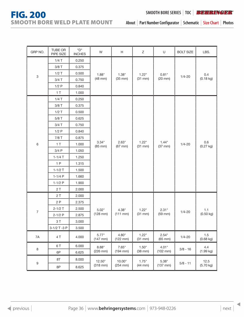
GRP NO.TUBE OR PIPE SIZE
"D" INCHES
W H Z U BOLT SIZE LBS.
3
1/4 T 0.250
1.88" (48 mm)
1.38" (35 mm)
1.22" (31 mm)
0.81" (20 mm)
1/4-200.4
(0.18 kg)
3/8 T 0.375
1/2 T 0.500
3/4 T 0.750
1/2 P 0.840
1 T 1.000
6
1/4 T 0.250
3.34" (85 mm)
2.63" (67 mm)
1.22" (31 mm)
1.44" (37 mm)
1/4-200.6
(0.27 kg)
3/8 T 0.375
1/2 T 0.500
5/8 T 0.625
3/4 T 0.750
1/2 P 0.840
7/8 T 0.875
1 T 1.000
3/4 P 1.050
1-1/4 T 1.250
1 P 1.315
1-1/2 T 1.500
1-1/4 P 1.660
1-1/2 P 1.900
2 T 2.000
7
2 T 2.000
5.02" (128 mm)
4.38" (111 mm)
1.22" (31 mm)
2.31" (59 mm)
1/4-201.1
(0.50 kg)
2 P 2.375
2-1/2 T 2.500
2-1/2 P 2.875
3 T 3.000
3-1/2 T -3 P 3.500
7A 4 T 4.0005.77"
(147 mm)4.80"
(122 mm)1.22"
(31 mm)2.54"
(65 mm)1/4-20
1.5(0.68 kg)
86 T 6.000 8.88"
(226 mm)7.65"
(194 mm)1.50"
(38 mm) 4.01"
(102 mm)3/8 - 16
4.4(1.99 kg)6P 6.625
98T 8.000 12.50"
(318 mm)10.00"
(254 mm)1.75"
(44 mm)5.38"
(137 mm)5/8 - 11
12.5(5.70 kg)8P 8.625
FIG . 200SMOOTH BORE WELD PLATE MOUNT About | Part Number Configurator | Schematic | Size Chart | Photos
SMOOTH BORe SeRIeS | TOC |
Page 37 | www.behringersystems.com | 973-948-0226 | next | | previous |
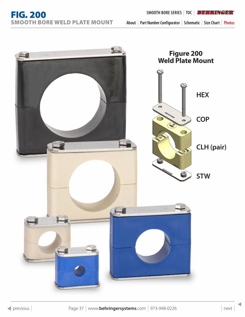
Figure 200 Weld plate Mount
HEX
COP
CLH (pair)
STW
FIG . 200SMOOTH BORE WELD PLATE MOUNT About | Part Number Configurator | Schematic | Size Chart | Photos
SMOOTH BORe SeRIeS | TOC |
Page 38 | www.behringersystems.com | 973-948-0226 | next | | previous |
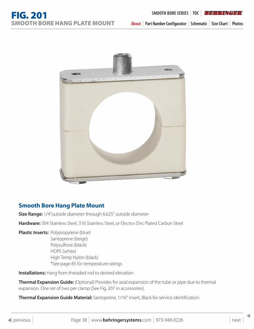
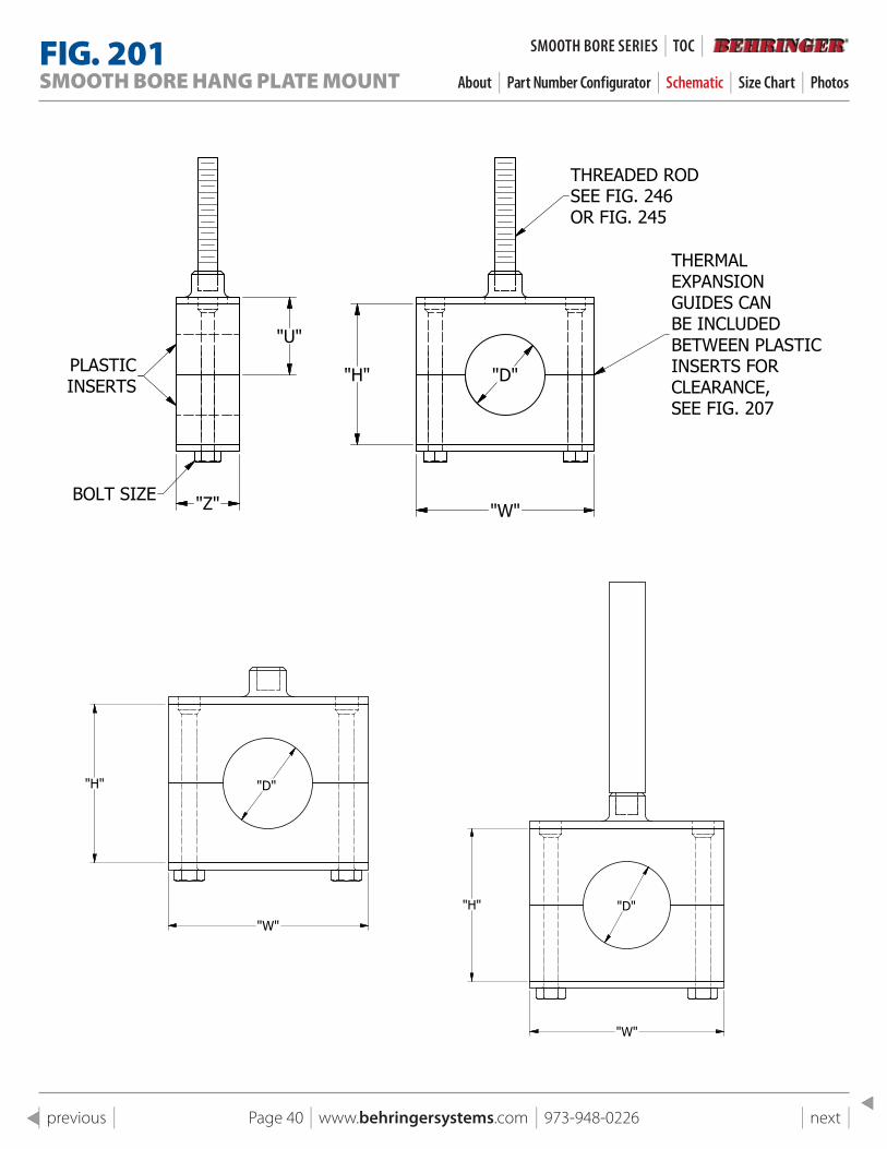
FIG . 201SMOOTH BORE HANG PLATE MOUNT About | Part Number Configurator | Schematic | Size Chart | Photos
smooth Bore Hang plate MountSize Range: 1/4"outside diameter through 6.625" outside diameter
Hardware: 304 Stainless Steel, 316 Stainless Steel, or Electro-Zinc Plated Carbon Steel
Plastic Inserts: Polypropylene (blue)Santoprene (beige) Polysulfone (black) HDPE (white) High Temp Nylon (black) *See page 85 for temperature ratings
Installations: Hang from threaded rod to desired elevation.
Thermal Expansion Guide: (Optional) Provides for axial expansion of the tube or pipe due to thermal expansion. One set of two per clamp (See Fig. 207 in accessories).
Thermal Expansion Guide Material: Santoprene, 1/16" insert, Black for service identification.
SMOOTH BORe SeRIeS | TOC |
Page 39 | www.behringersystems.com | 973-948-0226 | next | | previous |
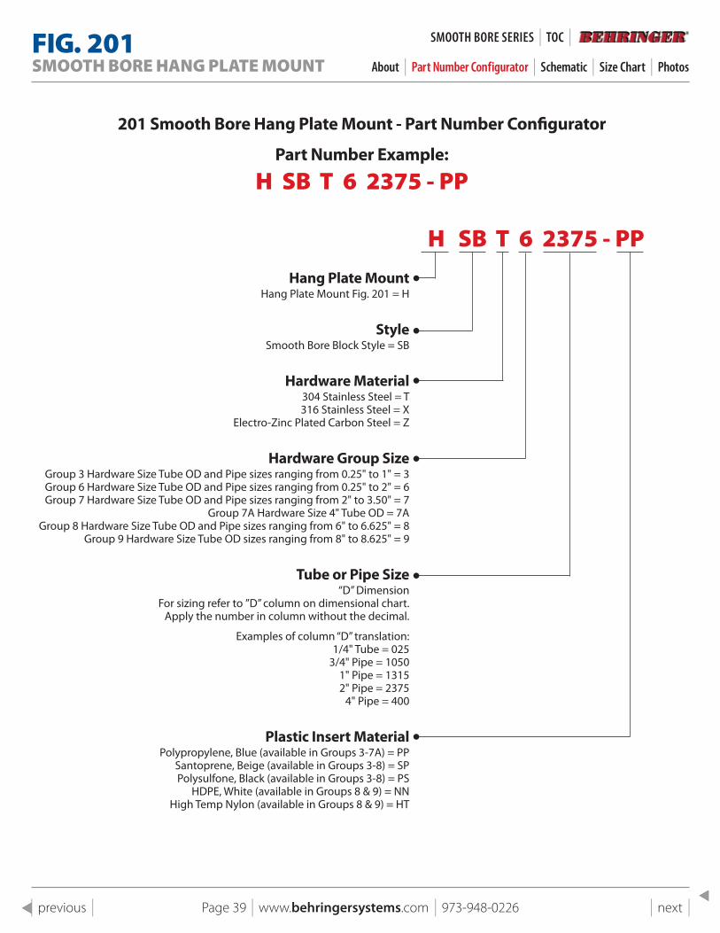
201 smooth Bore Hang plate Mount - part Number Configurator
part Number Example:
H SB T 6 2375 - PP
H SB T 6 2375 - PPHang plate Mount
Hang Plate Mount Fig. 201 = H
styleSmooth Bore Block Style = SB
Hardware Material304 Stainless Steel = T 316 Stainless Steel = X
Electro-Zinc Plated Carbon Steel = Z
Hardware Group sizeGroup 3 Hardware Size Tube OD and Pipe sizes ranging from 0.25" to 1" = 3 Group 6 Hardware Size Tube OD and Pipe sizes ranging from 0.25" to 2" = 6 Group 7 Hardware Size Tube OD and Pipe sizes ranging from 2" to 3.50" = 7
Group 7A Hardware Size 4" Tube OD = 7AGroup 8 Hardware Size Tube OD and Pipe sizes ranging from 6" to 6.625" = 8
Group 9 Hardware Size Tube OD sizes ranging from 8" to 8.625" = 9
Tube or pipe size“D” Dimension
For sizing refer to ”D” column on dimensional chart.Apply the number in column without the decimal.
Examples of column “D” translation:1/4" Tube = 025
3/4" Pipe = 10501" Pipe = 13152" Pipe = 2375
4" Pipe = 400
plastic Insert Material Polypropylene, Blue (available in Groups 3-7A) = PP
Santoprene, Beige (available in Groups 3-8) = SP Polysulfone, Black (available in Groups 3-8) = PS
HDPE, White (available in Groups 8 & 9) = NN High Temp Nylon (available in Groups 8 & 9) = HT
FIG . 201SMOOTH BORE HANG PLATE MOUNT About | Part Number Configurator | Schematic | Size Chart | Photos
SMOOTH BORe SeRIeS | TOC |
Page 40 | www.behringersystems.com | 973-948-0226 | next | | previous |
1
1
2
2
3
3
4
4
A A
B B
C C
D D
SHEET 1 OF 1
DRAWN
CHECKED
QA
MFG
APPROVED
11/4/2018
DWG NO
201 pg 20 no rod
TITLE
Fig 201 Hang Plate Mount No Rod
SIZE
CSCALE
REV
"D"
"W"
"H"
1
1
2
2
3
3
4
4
A A
B B
C C
D D
SHEET 1 OF 1
DRAWN
CHECKED
QA
MFG
APPROVED
11/4/2018
DWG NO
201 pg 20 rod toe
TITLE
Fig 201 Hang Plate Mount w/Rod
SIZE
CSCALE
REV
"D"
"W"
"H"
1
1
2
2
3
3
4
4
A A
B B
C C
D D
SHEET 1 OF 1
DRAWN
CHECKED
QA
MFG
APPROVED
11/4/2018
DWG NO
201 pg 20 Assembly
TITLE
Fig 201 Hang Plate Mount
SIZE
CSCALE
REV
"U"
"Z"BOLT SIZE
PLASTICINSERTS
"W"
THREADED RODSEE FIG. 246OR FIG. 245
"H"
THERMALEXPANSIONGUIDES CANBE INCLUDEDBETWEEN PLASTICINSERTS FORCLEARANCE,SEE FIG. 207
"D"
1
1
2
2
3
3
4
4
A A
B B
C C
D D
SHEET 1 OF 1
DRAWN
CHECKED
QA
MFG
APPROVED
11/4/2018
DWG NO
201 pg 20 Assembly
TITLE
Fig 201 Hang Plate Mount
SIZE
CSCALE
REV
"U"
"Z"BOLT SIZE
PLASTICINSERTS
"W"
THREADED RODSEE FIG. 246OR FIG. 245
"H"
THERMALEXPANSIONGUIDES CANBE INCLUDEDBETWEEN PLASTICINSERTS FORCLEARANCE,SEE FIG. 207
"D"
FIG . 201SMOOTH BORE HANG PLATE MOUNT About | Part Number Configurator | Schematic | Size Chart | Photos
SMOOTH BORe SeRIeS | TOC |
Page 41 | www.behringersystems.com | 973-948-0226 | next | | previous |
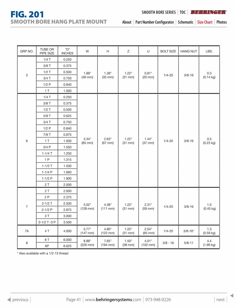
GRP NO.TUBE OR PIPE SIZE
"D" INCHES
W H Z U BOLT SIZE HANG NUT LBS.
3
1/4 T 0.250
1.88" (48 mm)
1.38" (35 mm)
1.22" (31 mm)
0.81" (20 mm)
1/4-20 3/8-160.3
(0.14 kg)
3/8 T 0.375
1/2 T 0.500
3/4 T 0.750
1/2 P 0.840
1 T 1.000
6
1/4 T 0.250
3.34" (85 mm)
2.63" (67 mm)
1.22" (31 mm)
1.44" (37 mm)
1/4-20 3/8-160.5
(0.23 kg)
3/8 T 0.375
1/2 T 0.500
5/8 T 0.625
3/4 T 0.750
1/2 P 0.840
7/8 T 0.875
1 T 1.000
3/4 P 1.050
1-1/4 T 1.250
1 P 1.315
1-1/2 T 1.500
1-1/4 P 1.660
1-1/2 P 1.900
2 T 2.000
7
2 T 2.000
5.02" (128 mm)
4.38" (111 mm)
1.22" (31 mm)
2.31" (59 mm)
1/4-20 3/8-161.0
(0.45 kg)
2 P 2.375
2-1/2 T 2.500
2-1/2 P 2.875
3 T 3.000
3-1/2 T -3 P 3.500
7A 4 T 4.0005.77"
(147 mm)4.80"
(122 mm)1.22"
(31 mm)2.54"
(65 mm)1/4-20 3/8-16*
1.3(0.59 kg)
86 T 6.000 8.88"
(226 mm)7.65"
(194 mm)1.50"
(38 mm) 4.01"
(102 mm)3/8 - 16 5/8-11
4.4(1.99 kg)6P 6.625
* Also available with a 1/2-13 thread
FIG . 201SMOOTH BORE HANG PLATE MOUNT About | Part Number Configurator | Schematic | Size Chart | Photos
SMOOTH BORe SeRIeS | TOC |
Page 42 | www.behringersystems.com | 973-948-0226 | next | | previous |
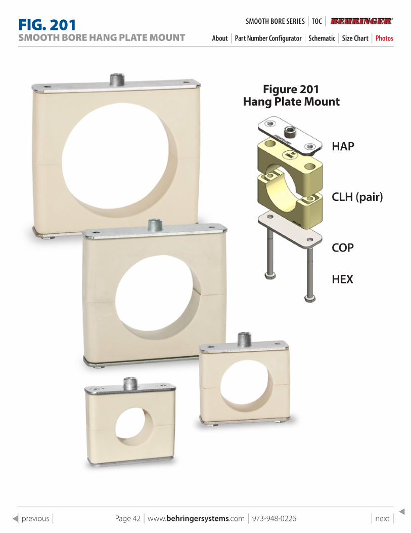
Figure 201 Hang plate Mount
HEX
COP
CLH (pair)
HAP
FIG . 201SMOOTH BORE HANG PLATE MOUNT About | Part Number Configurator | Schematic | Size Chart | Photos
SMOOTH BORe SeRIeS | TOC |
Page 43 | www.behringersystems.com | 973-948-0226 | next | | previous |
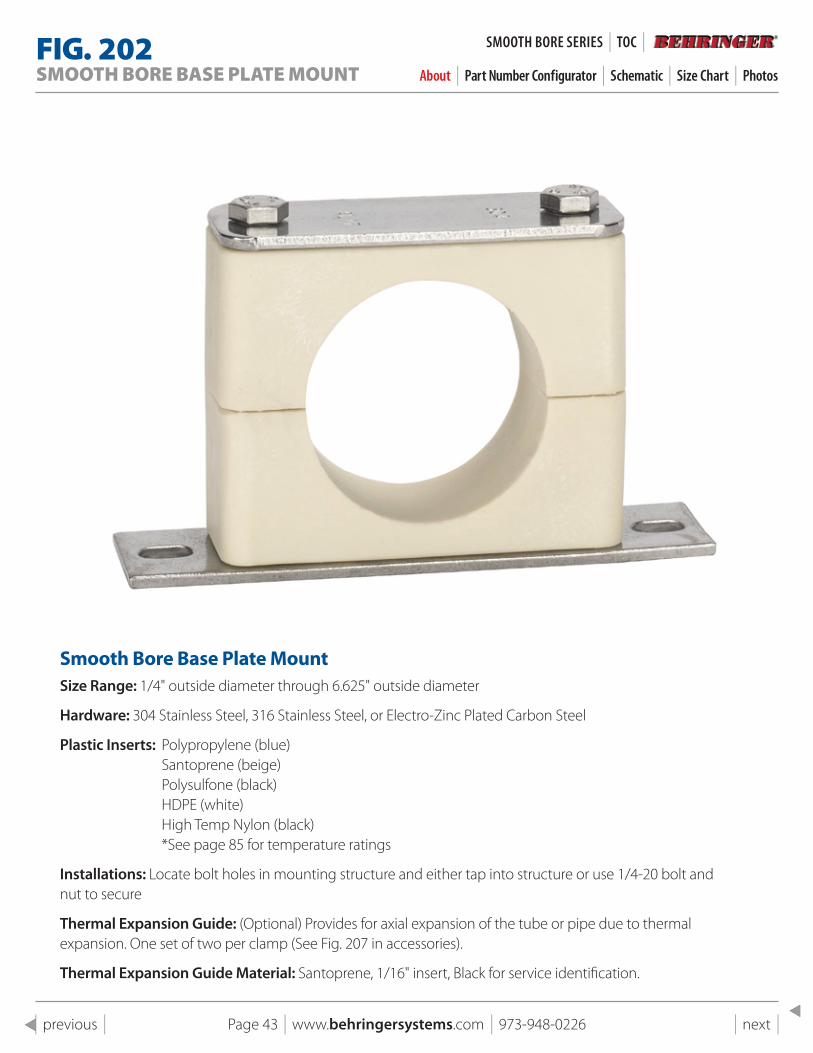
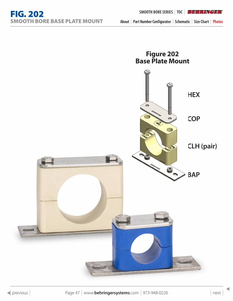
FIG . 202SMOOTH BORE BASE PLATE MOUNT About | Part Number Configurator | Schematic | Size Chart | Photos
smooth Bore Base plate MountSize Range: 1/4" outside diameter through 6.625" outside diameter
Hardware: 304 Stainless Steel, 316 Stainless Steel, or Electro-Zinc Plated Carbon Steel
Plastic Inserts: Polypropylene (blue)Santoprene (beige) Polysulfone (black) HDPE (white) High Temp Nylon (black) *See page 85 for temperature ratings
Installations: Locate bolt holes in mounting structure and either tap into structure or use 1/4-20 bolt and nut to secure
Thermal Expansion Guide: (Optional) Provides for axial expansion of the tube or pipe due to thermal expansion. One set of two per clamp (See Fig. 207 in accessories).
Thermal Expansion Guide Material: Santoprene, 1/16" insert, Black for service identification.
SMOOTH BORe SeRIeS | TOC |
Page 44 | www.behringersystems.com | 973-948-0226 | next | | previous |
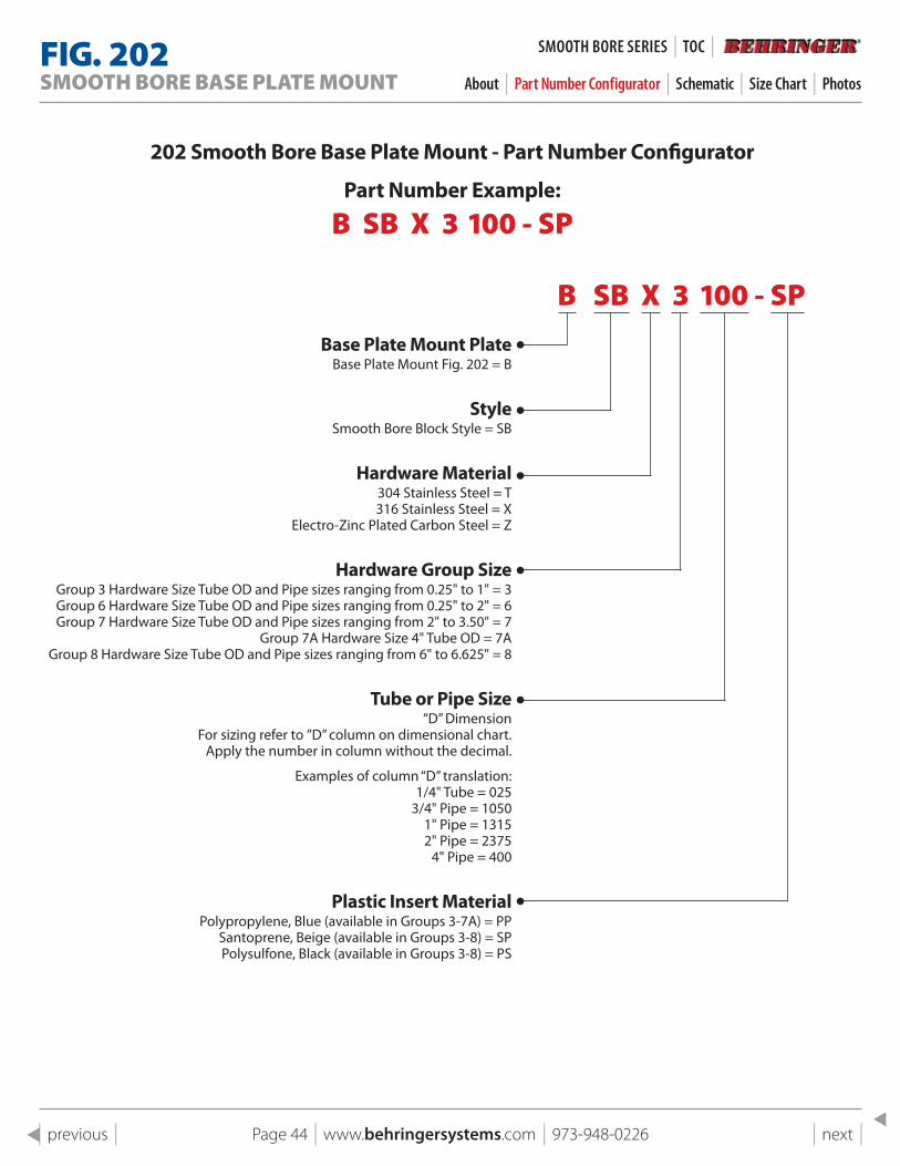
202 smooth Bore Base plate Mount - part Number Configurator
part Number Example:
B SB X 3 100 - SP
B SB X 3 100 - SPBase plate Mount plate
Base Plate Mount Fig. 202 = B
styleSmooth Bore Block Style = SB
Hardware Material304 Stainless Steel = T 316 Stainless Steel = X
Electro-Zinc Plated Carbon Steel = Z
Hardware Group sizeGroup 3 Hardware Size Tube OD and Pipe sizes ranging from 0.25" to 1" = 3 Group 6 Hardware Size Tube OD and Pipe sizes ranging from 0.25" to 2" = 6 Group 7 Hardware Size Tube OD and Pipe sizes ranging from 2" to 3.50" = 7
Group 7A Hardware Size 4" Tube OD = 7AGroup 8 Hardware Size Tube OD and Pipe sizes ranging from 6" to 6.625" = 8
Tube or pipe size“D” Dimension
For sizing refer to ”D” column on dimensional chart.Apply the number in column without the decimal.
Examples of column “D” translation:1/4" Tube = 025
3/4" Pipe = 10501" Pipe = 13152" Pipe = 2375
4" Pipe = 400
plastic Insert Material Polypropylene, Blue (available in Groups 3-7A) = PP
Santoprene, Beige (available in Groups 3-8) = SP Polysulfone, Black (available in Groups 3-8) = PS
FIG . 202SMOOTH BORE BASE PLATE MOUNT About | Part Number Configurator | Schematic | Size Chart | Photos
SMOOTH BORe SeRIeS | TOC |

Page 45 | www.behringersystems.com | 973-948-0226 | next | | previous |
1
1
2
2
3
3
4
4
A A
B B
C C
D D
SHEET 1 OF 1
DRAWN
CHECKED
QA
MFG
APPROVED
11/24/2018
DWG NO
202 pg 21 Assembly
TITLE
Fig 202 Base Plate Mount
SIZE
CSCALE
REV
"D"
"W"
"H"
FACE OFSUPPORTINGSTRUCTURE
3/8" (TYP.)
7/16 x 9/32SLOTS FORMOUNTINGBOLTS
PLASTICINSERTS
1/4-20MOUNTING BOLTS(NOT INCLUDED)
BOLT SIZE
"U"
"Z"
THERMALEXPANSIONGUIDES CANBE INCLUDEDBETWEENPLASTICINSERTS FORCLEARANCE,SEE FIG. 207
FACE OFSUPPORTINGSTRUCTURE
"K"
1
1
2
2
3
3
4
4
A A
B B
C C
D D
SHEET 1 OF 1
DRAWN
CHECKED
QA
MFG
APPROVED
11/24/2018
DWG NO
202 pg 21 Assembly
TITLE
Fig 202 Base Plate Mount
SIZE
CSCALE
REV
"D"
"W"
"H"
FACE OFSUPPORTINGSTRUCTURE
3/8" (TYP.)
7/16 x 9/32SLOTS FORMOUNTINGBOLTS
PLASTICINSERTS
1/4-20MOUNTING BOLTS(NOT INCLUDED)
BOLT SIZE
"U"
"Z"
THERMALEXPANSIONGUIDES CANBE INCLUDEDBETWEENPLASTICINSERTS FORCLEARANCE,SEE FIG. 207
FACE OFSUPPORTINGSTRUCTURE
"K"
FIG . 202SMOOTH BORE BASE PLATE MOUNT About | Part Number Configurator | Schematic | Size Chart | Photos
SMOOTH BORe SeRIeS | TOC |
Page 46 | www.behringersystems.com | 973-948-0226 | next | | previous |
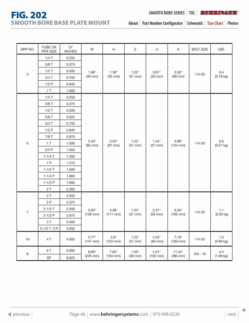
GRP NO.TUBE OR PIPE SIZE
"D" INCHES
W H Z U K BOLT SIZE LBS.
3
1/4 T 0.250
1.88" (48 mm)
1.38" (35 mm)
1.22" (31 mm)
0.81" (20 mm)
3.50"(89 mm)
1/4-200.4
(0.18 kg)
3/8 T 0.375
1/2 T 0.500
3/4 T 0.750
1/2 P 0.840
1 T 1.000
6
1/4 T 0.250
3.34" (85 mm)
2.63" (67 mm)
1.22" (31 mm)
1.44" (37 mm)
4.88"(124 mm)
1/4-200.6
(0.27 kg)
3/8 T 0.375
1/2 T 0.500
5/8 T 0.625
3/4 T 0.750
1/2 P 0.840
7/8 T 0.875
1 T 1.000
3/4 P 1.050
1-1/4 T 1.250
1 P 1.315
1-1/2 T 1.500
1-1/4 P 1.660
1-1/2 P 1.900
2 T 2.000
7
2 T 2.000
5.02" (128 mm)
4.38" (111 mm)
1.22" (31 mm)
2.31" (59 mm)
6.50"(165 mm)
1/4-201.1
(0.50 kg)
2 P 2.375
2-1/2 T 2.500
2-1/2 P 2.875
3 T 3.000
3-1/2 T -3 P 3.500
7A 4 T 4.0005.77"
(147 mm)4.8"
(122 mm)1.22"
(31 mm)2.54"
(65 mm)7.19"
(183 mm)1/4-20
1.5(0.68 kg)
86 T 6.000 8.88"
(226 mm)7.65"
(194 mm)1.50"
(38 mm) 4.01"
(102 mm)11.25"
286 mm)3/8 - 16
4.4(1.99 kg)6P 6.625
FIG . 202SMOOTH BORE BASE PLATE MOUNT About | Part Number Configurator | Schematic | Size Chart | Photos
SMOOTH BORe SeRIeS | TOC |
Page 47 | www.behringersystems.com | 973-948-0226 | next | | previous |
Figure 202 Base plate Mount
HEX
COP
CLH (pair)
BAP
FIG . 202SMOOTH BORE BASE PLATE MOUNT About | Part Number Configurator | Schematic | Size Chart | Photos
SMOOTH BORe SeRIeS | TOC |
Page 48 | www.behringersystems.com | 973-948-0226 | next | | previous |
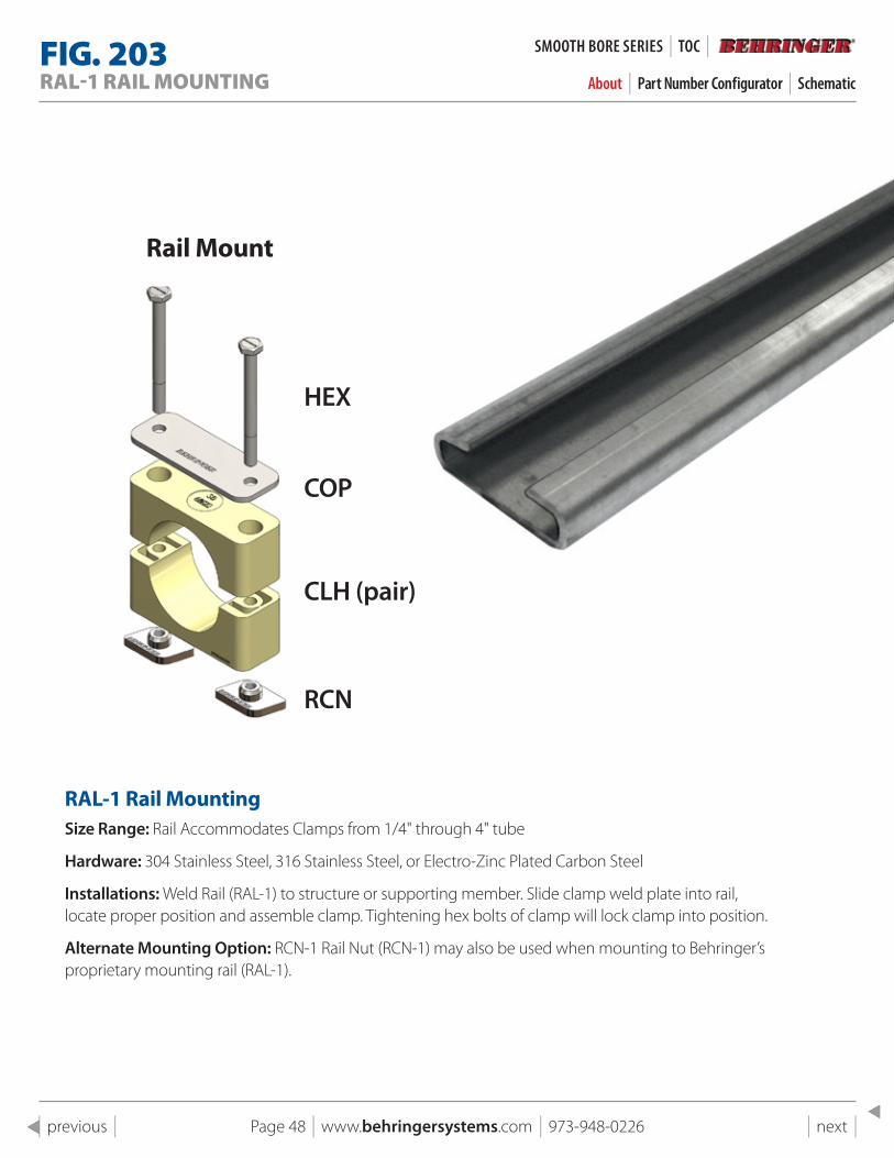
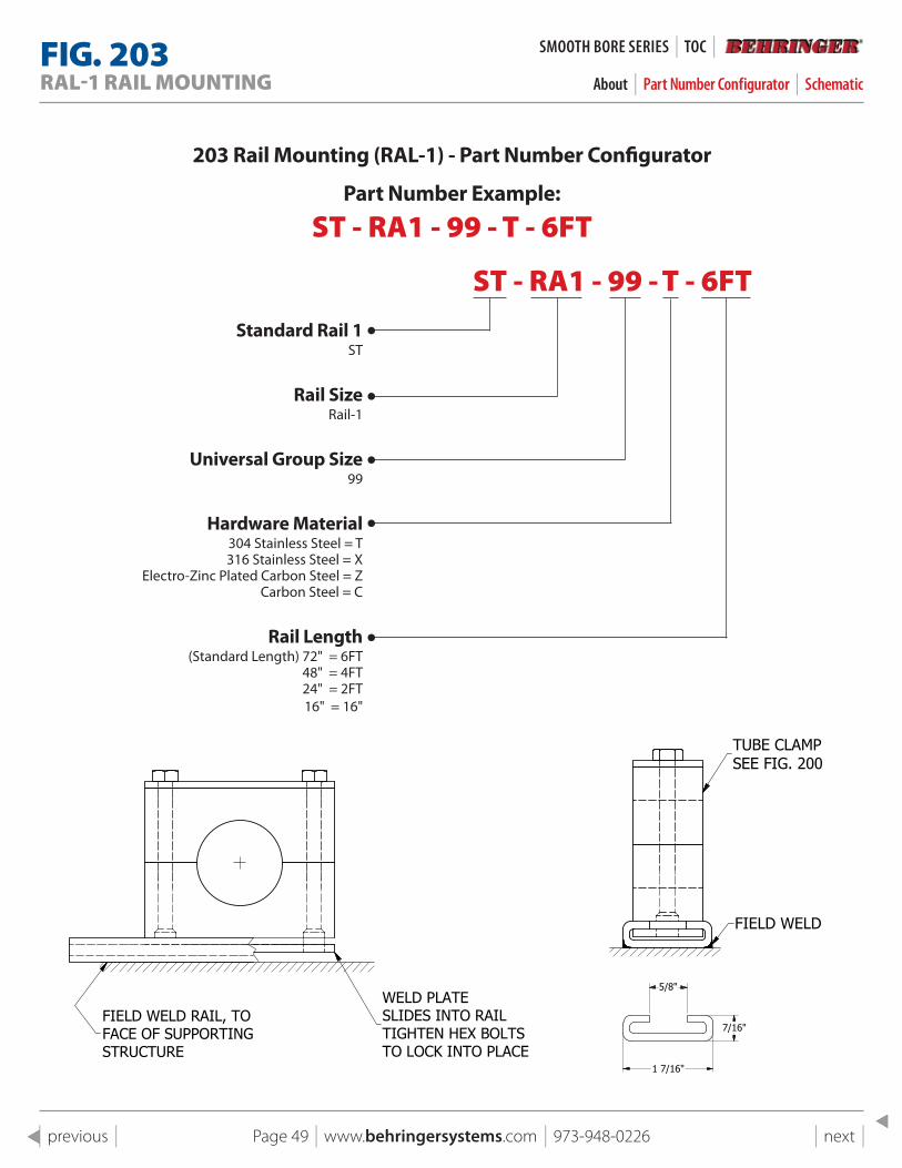
FIG . 203RAL-1 RAIL MOUNTING About | Part Number Configurator | Schematic
RAl-1 Rail MountingSize Range: Rail Accommodates Clamps from 1/4" through 4" tube
Hardware: 304 Stainless Steel, 316 Stainless Steel, or Electro-Zinc Plated Carbon Steel
Installations: Weld Rail (RAL-1) to structure or supporting member. Slide clamp weld plate into rail, locate proper position and assemble clamp. Tightening hex bolts of clamp will lock clamp into position.
Alternate Mounting Option: RCN-1 Rail Nut (RCN-1) may also be used when mounting to Behringer’s proprietary mounting rail (RAL-1).
Rail Mount
HEX
COP
CLH (pair)
RCN
SMOOTH BORe SeRIeS | TOC |
Page 49 | www.behringersystems.com | 973-948-0226 | next | | previous |
203 Rail Mounting (RAl-1) - part Number Configurator
part Number Example:
ST - RA1 - 99 - T - 6FT
ST - RA1 - 99 - T - 6FTstandard Rail 1
ST
Rail sizeRail-1
Universal Group size99
Hardware Material304 Stainless Steel = T 316 Stainless Steel = X
Electro-Zinc Plated Carbon Steel = ZCarbon Steel = C
Rail length(Standard Length) 72" = 6FT
48" = 4FT 24" = 2FT 16" = 16"
1
1
2
2
3
3
4
4
A A
B B
C C
D D
SHEET 1 OF 1
DRAWN
CHECKED
QA
MFG
APPROVED
11/4/2018
DWG NO
203 pg 22 Assembly
TITLE
Fig 203 Ral-1 Rail Mounting
SIZE
CSCALE
REV
WELD PLATESLIDES INTO RAILTIGHTEN HEX BOLTSTO LOCK INTO PLACE
FIELD WELD RAIL, TOFACE OF SUPPORTINGSTRUCTURE
TUBE CLAMPSEE FIG. 200
FIELD WELD
5/8"
1 7/16"
7/16"
1
1
2
2
3
3
4
4
A A
B B
C C
D D
SHEET 1 OF 1
DRAWN
CHECKED
QA
MFG
APPROVED
11/4/2018
DWG NO
203 pg 22 Assembly
TITLE
Fig 203 Ral-1 Rail Mounting
SIZE
CSCALE
REV
WELD PLATESLIDES INTO RAILTIGHTEN HEX BOLTSTO LOCK INTO PLACE
FIELD WELD RAIL, TOFACE OF SUPPORTINGSTRUCTURE
TUBE CLAMPSEE FIG. 200
FIELD WELD
5/8"
1 7/16"
7/16"
FIG . 203RAL-1 RAIL MOUNTING About | Part Number Configurator | Schematic
SMOOTH BORe SeRIeS | TOC |
Page 50 | www.behringersystems.com | 973-948-0226 | next | | previous |
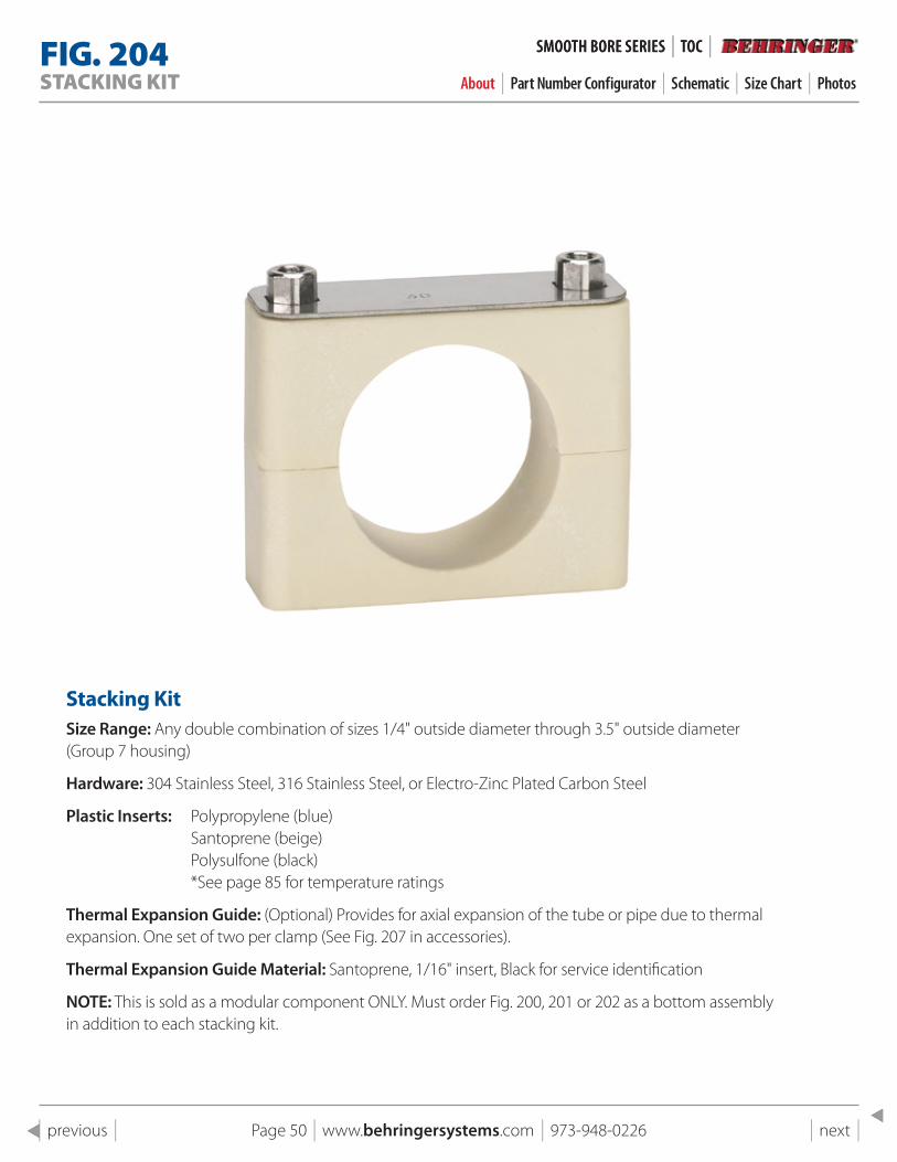
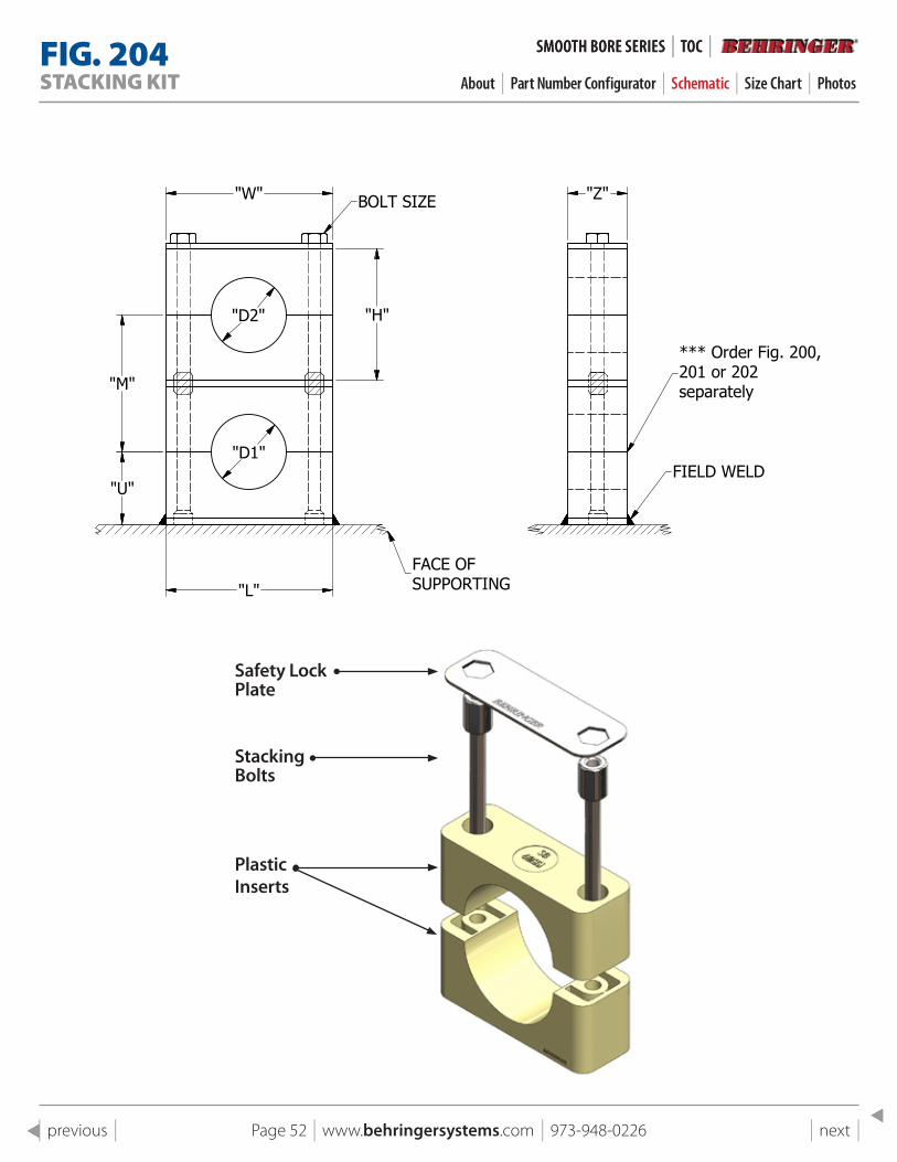
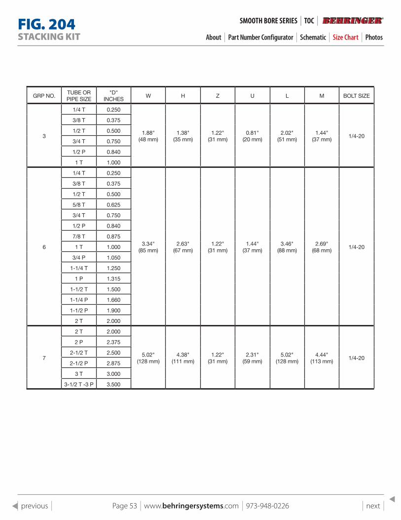
FIG . 204STACkING kIT About | Part Number Configurator | Schematic | Size Chart | Photos
SMOOTH BORe SeRIeS | TOC |
stacking KitSize Range: Any double combination of sizes 1/4" outside diameter through 3.5" outside diameter (Group 7 housing)
Hardware: 304 Stainless Steel, 316 Stainless Steel, or Electro-Zinc Plated Carbon Steel
Plastic Inserts: Polypropylene (blue) Santoprene (beige) Polysulfone (black) *See page 85 for temperature ratings
Thermal Expansion Guide: (Optional) Provides for axial expansion of the tube or pipe due to thermal expansion. One set of two per clamp (See Fig. 207 in accessories).
Thermal Expansion Guide Material: Santoprene, 1/16" insert, Black for service identification
NOTE: This is sold as a modular component ONLY. Must order Fig. 200, 201 or 202 as a bottom assembly in addition to each stacking kit.
SMOOTH BORe SeRIeS | TOC |
Page 51 | www.behringersystems.com | 973-948-0226 | next | | previous |
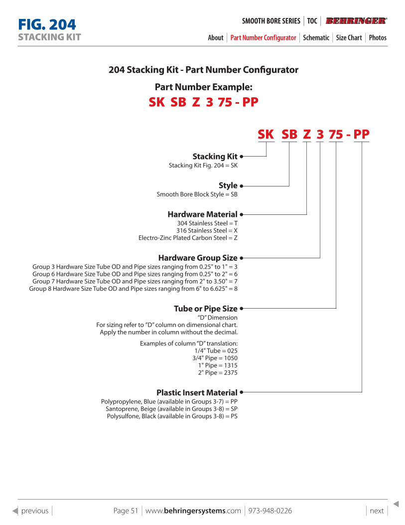
204 stacking Kit - part Number Configurator
part Number Example:
Sk SB Z 3 75 - PP
Sk SB Z 3 75 - PPstacking Kit
Stacking Kit Fig. 204 = SK
styleSmooth Bore Block Style = SB
Hardware Material304 Stainless Steel = T 316 Stainless Steel = X
Electro-Zinc Plated Carbon Steel = Z
Hardware Group sizeGroup 3 Hardware Size Tube OD and Pipe sizes ranging from 0.25" to 1" = 3 Group 6 Hardware Size Tube OD and Pipe sizes ranging from 0.25" to 2" = 6 Group 7 Hardware Size Tube OD and Pipe sizes ranging from 2" to 3.50" = 7
Group 8 Hardware Size Tube OD and Pipe sizes ranging from 6" to 6.625" = 8
Tube or pipe size“D” Dimension
For sizing refer to ”D” column on dimensional chart.Apply the number in column without the decimal.
Examples of column “D” translation:1/4" Tube = 025
3/4" Pipe = 10501" Pipe = 13152" Pipe = 2375
plastic Insert Material Polypropylene, Blue (available in Groups 3-7) = PP
Santoprene, Beige (available in Groups 3-8) = SP Polysulfone, Black (available in Groups 3-8) = PS
FIG . 204STACkING kIT About | Part Number Configurator | Schematic | Size Chart | Photos
SMOOTH BORe SeRIeS | TOC | SMOOTH BORe SeRIeS | TOC |
Page 52 | www.behringersystems.com | 973-948-0226 | next | | previous |
Safety Lock Plate
Stacking Bolts
PlasticInserts
1
1
2
2
3
3
4
4
A A
B B
C C
D D
SHEET 1 OF 1
DRAWN
CHECKED
QA
MFG
APPROVED
11/4/2018
DWG NO
204 pg 23 Assembly
TITLE
Fig 204 Stacking Kit
SIZE
CSCALE
REV
"D1"
"D2"
"W"
"H"
"M"
"U"
"L"
FACE OFSUPPORTING
BOLT SIZE
FIELD WELD
*** Order Fig. 200, 201 or 202separately
"Z"
FIG . 204STACkING kIT About | Part Number Configurator | Schematic | Size Chart | Photos
SMOOTH BORe SeRIeS | TOC | SMOOTH BORe SeRIeS | TOC |
Page 53 | www.behringersystems.com | 973-948-0226 | next | | previous |
GRP NO.TUBE OR PIPE SIZE
"D" INCHES
W H Z U L M BOLT SIZE
3
1/4 T 0.250
1.88" (48 mm)
1.38" (35 mm)
1.22" (31 mm)
0.81" (20 mm)
2.02"(51 mm)
1.44"(37 mm)
1/4-20
3/8 T 0.375
1/2 T 0.500
3/4 T 0.750
1/2 P 0.840
1 T 1.000
6
1/4 T 0.250
3.34" (85 mm)
2.63" (67 mm)
1.22" (31 mm)
1.44" (37 mm)
3.46"(88 mm)
2.69"(68 mm)
1/4-20
3/8 T 0.375
1/2 T 0.500
5/8 T 0.625
3/4 T 0.750
1/2 P 0.840
7/8 T 0.875
1 T 1.000
3/4 P 1.050
1-1/4 T 1.250
1 P 1.315
1-1/2 T 1.500
1-1/4 P 1.660
1-1/2 P 1.900
2 T 2.000
7
2 T 2.000
5.02" (128 mm)
4.38" (111 mm)
1.22" (31 mm)
2.31" (59 mm)
5.02"(128 mm)
4.44"(113 mm)
1/4-20
2 P 2.375
2-1/2 T 2.500
2-1/2 P 2.875
3 T 3.000
3-1/2 T -3 P 3.500
FIG . 204STACkING kIT About | Part Number Configurator | Schematic | Size Chart | Photos
SMOOTH BORe SeRIeS | TOC | SMOOTH BORe SeRIeS | TOC |
Page 54 | www.behringersystems.com | 973-948-0226 | next | | previous |
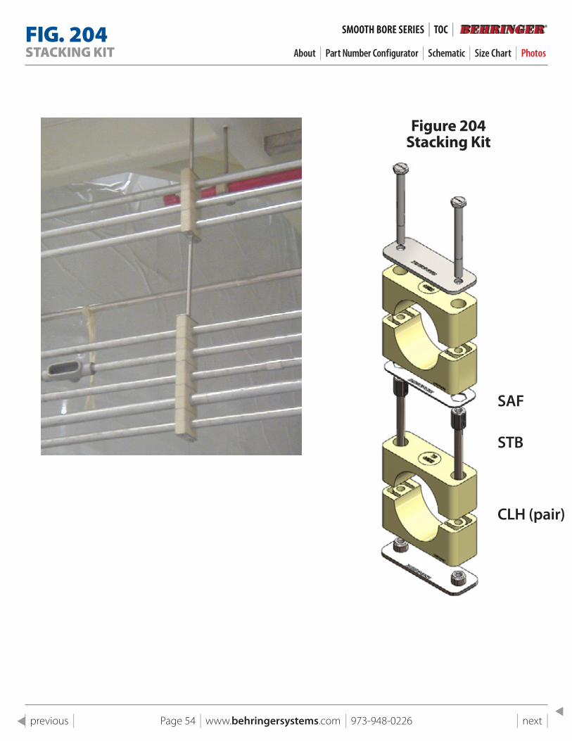
Figure 204 stacking Kit
SAF
STB
CLH (pair)
FIG . 204STACkING kIT About | Part Number Configurator | Schematic | Size Chart | Photos
SMOOTH BORe SeRIeS | TOC | SMOOTH BORe SeRIeS | TOC |
Page 55 | www.behringersystems.com | 973-948-0226 | next | | previous |
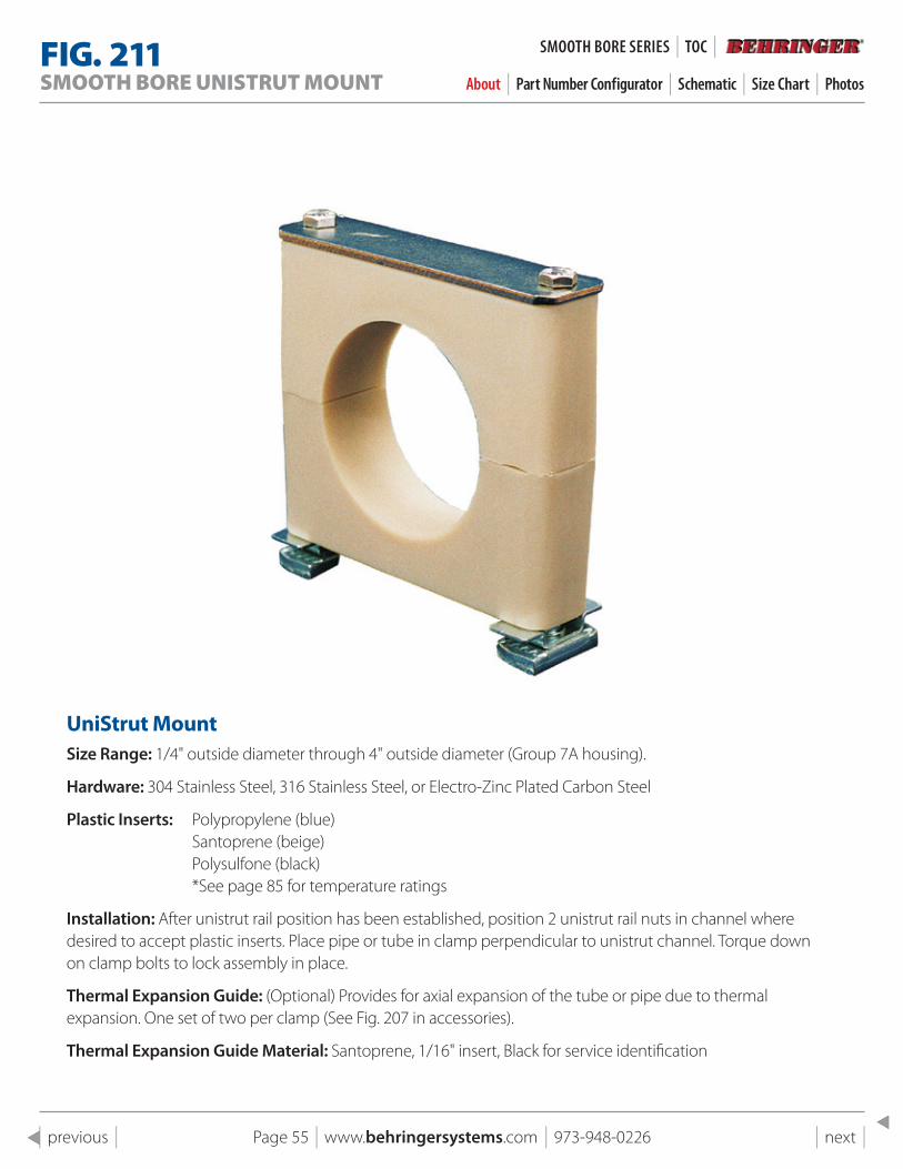
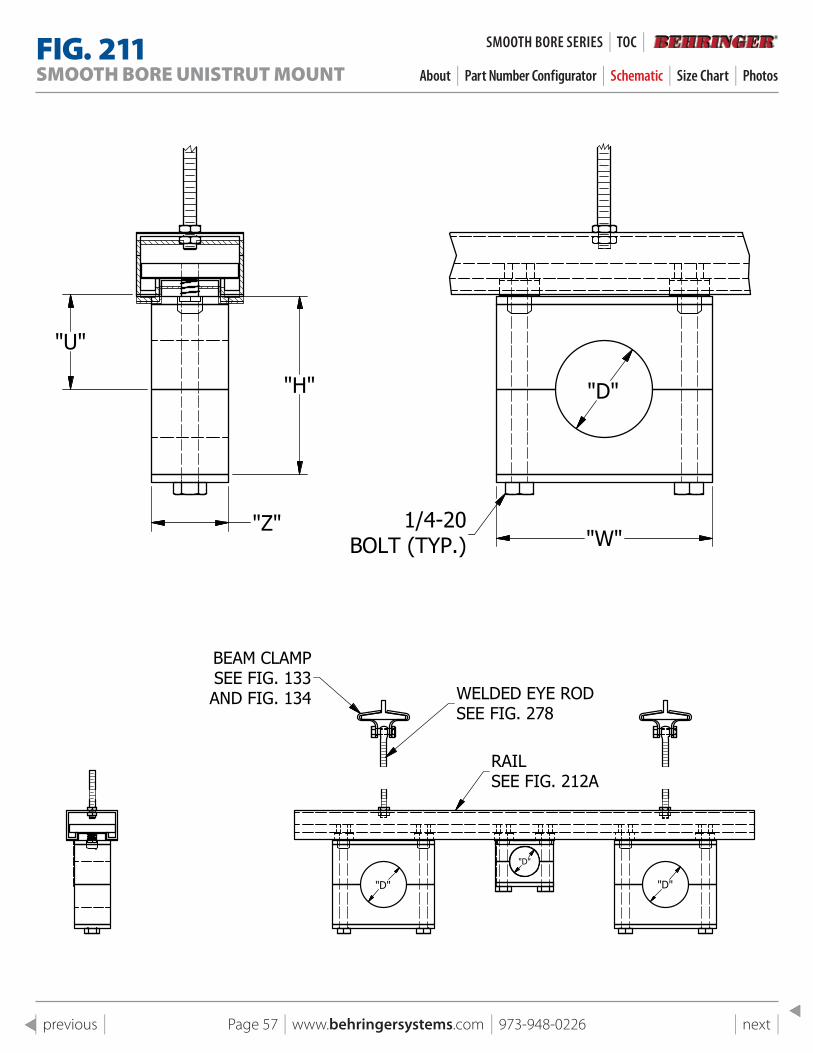
FIG . 211SMOOTH BORE UNISTRUT MOUNT About | Part Number Configurator | Schematic | Size Chart | Photos
Unistrut MountSize Range: 1/4" outside diameter through 4" outside diameter (Group 7A housing).
Hardware: 304 Stainless Steel, 316 Stainless Steel, or Electro-Zinc Plated Carbon Steel
Plastic Inserts: Polypropylene (blue) Santoprene (beige) Polysulfone (black) *See page 85 for temperature ratings
Installation: After unistrut rail position has been established, position 2 unistrut rail nuts in channel where desired to accept plastic inserts. Place pipe or tube in clamp perpendicular to unistrut channel. Torque down on clamp bolts to lock assembly in place.
Thermal Expansion Guide: (Optional) Provides for axial expansion of the tube or pipe due to thermal expansion. One set of two per clamp (See Fig. 207 in accessories).
Thermal Expansion Guide Material: Santoprene, 1/16" insert, Black for service identification
SMOOTH BORe SeRIeS | TOC |
Page 56 | www.behringersystems.com | 973-948-0226 | next | | previous |
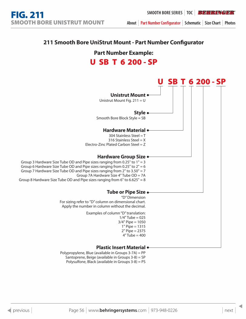
211 smooth Bore Unistrut Mount - part Number Configurator
part Number Example:
U SB T 6 200 - SP
U SB T 6 200 - SPUnistrut Mount
Unistrut Mount Fig. 211 = U
styleSmooth Bore Block Style = SB
Hardware Material304 Stainless Steel = T 316 Stainless Steel = X
Electro-Zinc Plated Carbon Steel = Z
Hardware Group sizeGroup 3 Hardware Size Tube OD and Pipe sizes ranging from 0.25" to 1" = 3 Group 6 Hardware Size Tube OD and Pipe sizes ranging from 0.25" to 2" = 6 Group 7 Hardware Size Tube OD and Pipe sizes ranging from 2" to 3.50" = 7
Group 7A Hardware Size 4" Tube OD = 7A Group 8 Hardware Size Tube OD and Pipe sizes ranging from 6" to 6.625" = 8
Tube or pipe size“D” Dimension
For sizing refer to ”D” column on dimensional chart.Apply the number in column without the decimal.
Examples of column “D” translation:1/4" Tube = 025
3/4" Pipe = 10501" Pipe = 13152" Pipe = 23754" Tube = 400
plastic Insert Material Polypropylene, Blue (available in Groups 3-7A) = PP
Santoprene, Beige (available in Groups 3-8) = SP Polysulfone, Black (available in Groups 3-8) = PS
FIG . 211SMOOTH BORE UNISTRUT MOUNT About | Part Number Configurator | Schematic | Size Chart | Photos
SMOOTH BORe SeRIeS | TOC |
Page 57 | www.behringersystems.com | 973-948-0226 | next | | previous |
1
1
2
2
3
3
4
4
A A
B B
C C
D D
SHEET 1 OF 1
DRAWN
CHECKED
QA
MFG
APPROVED
11/4/2018
DWG NO
221 UniStrut Mount Clamp
TITLE
Fig 211 UniStrut Mount Clamp
SIZE
CSCALE
REV
"U"
"H"
"Z"
"D"
"W"1/4-20
BOLT (TYP.)
"D"
"D"
"D"
BEAM CLAMPSEE FIG. 133AND FIG. 134 WELDED EYE ROD
SEE FIG. 278
RAILSEE FIG. 212A
1
1
2
2
3
3
4
4
A A
B B
C C
D D
SHEET 1 OF 1
DRAWN
CHECKED
QA
MFG
APPROVED
11/4/2018
DWG NO
221 UniStrut Mount Clamp
TITLE
Fig 211 UniStrut Mount Clamp
SIZE
CSCALE
REV
"U"
"H"
"Z"
"D"
"W"1/4-20
BOLT (TYP.)
"D"
"D"
"D"
BEAM CLAMPSEE FIG. 133AND FIG. 134 WELDED EYE ROD
SEE FIG. 278
RAILSEE FIG. 212A
FIG . 211SMOOTH BORE UNISTRUT MOUNT About | Part Number Configurator | Schematic | Size Chart | Photos
SMOOTH BORe SeRIeS | TOC |
Page 58 | www.behringersystems.com | 973-948-0226 | next | | previous |
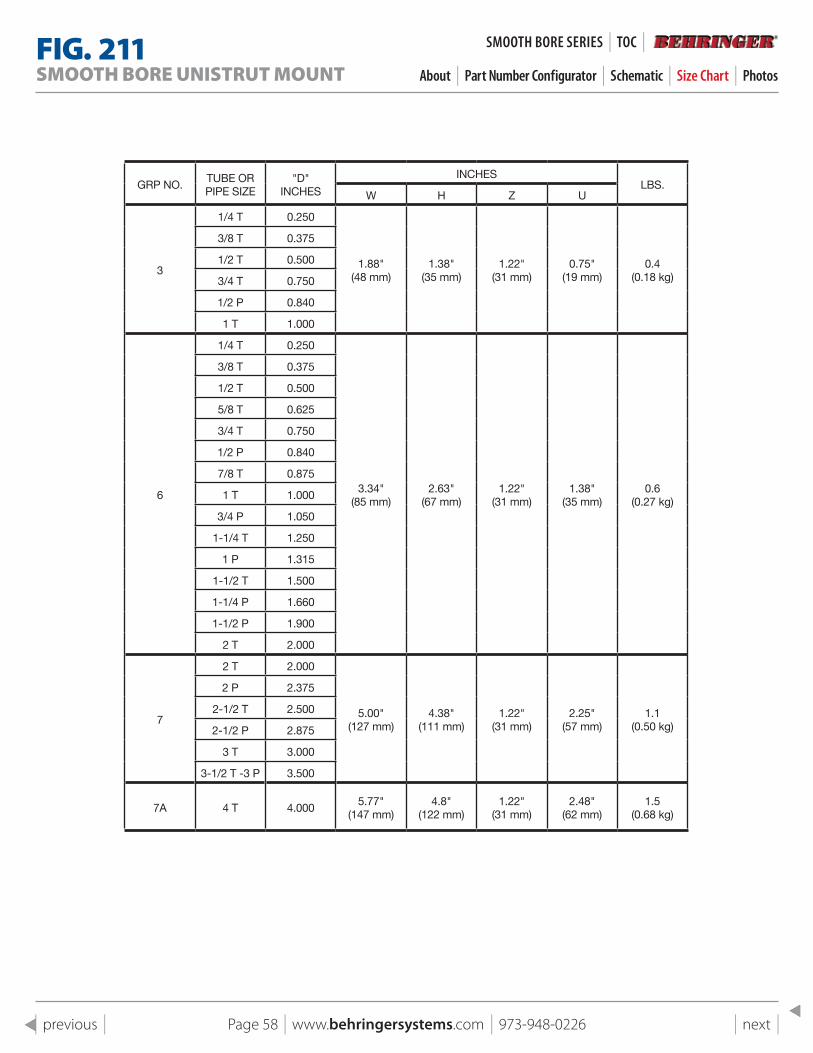
GRP NO.TUBE OR PIPE SIZE
"D" INCHES
INCHESLBS.
W H Z U
3
1/4 T 0.250
1.88" (48 mm)
1.38" (35 mm)
1.22" (31 mm)
0.75" (19 mm)
0.4(0.18 kg)
3/8 T 0.375
1/2 T 0.500
3/4 T 0.750
1/2 P 0.840
1 T 1.000
6
1/4 T 0.250
3.34" (85 mm)
2.63" (67 mm)
1.22" (31 mm)
1.38" (35 mm)
0.6(0.27 kg)
3/8 T 0.375
1/2 T 0.500
5/8 T 0.625
3/4 T 0.750
1/2 P 0.840
7/8 T 0.875
1 T 1.000
3/4 P 1.050
1-1/4 T 1.250
1 P 1.315
1-1/2 T 1.500
1-1/4 P 1.660
1-1/2 P 1.900
2 T 2.000
7
2 T 2.000
5.00" (127 mm)
4.38" (111 mm)
1.22" (31 mm)
2.25" (57 mm)
1.1(0.50 kg)
2 P 2.375
2-1/2 T 2.500
2-1/2 P 2.875
3 T 3.000
3-1/2 T -3 P 3.500
7A 4 T 4.0005.77"
(147 mm)4.8"
(122 mm)1.22"
(31 mm)2.48"
(62 mm)1.5
(0.68 kg)
FIG . 211SMOOTH BORE UNISTRUT MOUNT About | Part Number Configurator | Schematic | Size Chart | Photos
SMOOTH BORe SeRIeS | TOC |
Page 59 | www.behringersystems.com | 973-948-0226 | next | | previous |
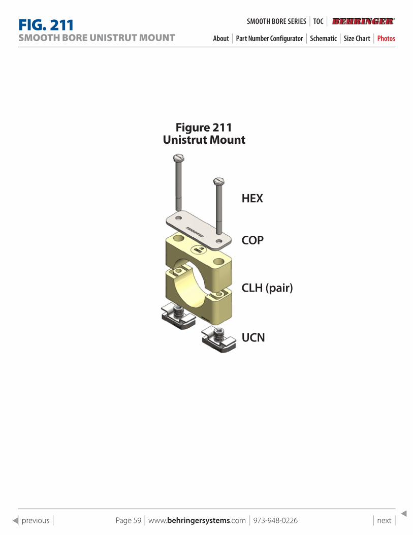
Figure 211 Unistrut Mount
HEX
COP
CLH (pair)
UCN
FIG . 211SMOOTH BORE UNISTRUT MOUNT About | Part Number Configurator | Schematic | Size Chart | Photos
SMOOTH BORe SeRIeS | TOC |
Page 60 | www.behringersystems.com | 973-948-0226 | next | | previous |
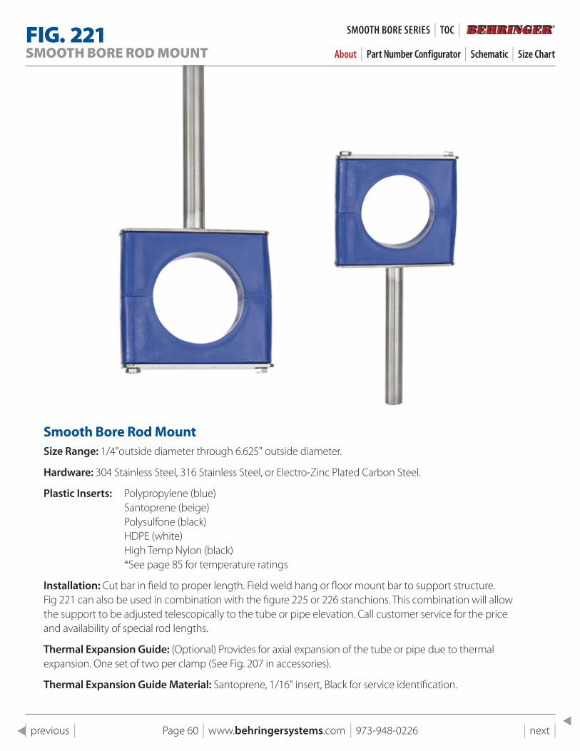
FIG . 221SMOOTH BORE ROD MOUNT About | Part Number Configurator | Schematic | Size Chart
smooth Bore Rod MountSize Range: 1/4"outside diameter through 6.625" outside diameter.
Hardware: 304 Stainless Steel, 316 Stainless Steel, or Electro-Zinc Plated Carbon Steel.
Plastic Inserts: Polypropylene (blue) Santoprene (beige) Polysulfone (black) HDPE (white) High Temp Nylon (black) *See page 85 for temperature ratings
Installation: Cut bar in field to proper length. Field weld hang or floor mount bar to support structure. Fig 221 can also be used in combination with the figure 225 or 226 stanchions. This combination will allow the support to be adjusted telescopically to the tube or pipe elevation. Call customer service for the price and availability of special rod lengths.
Thermal Expansion Guide: (Optional) Provides for axial expansion of the tube or pipe due to thermal expansion. One set of two per clamp (See Fig. 207 in accessories).
Thermal Expansion Guide Material: Santoprene, 1/16" insert, Black for service identification.
SMOOTH BORe SeRIeS | TOC |
Page 61 | www.behringersystems.com | 973-948-0226 | next | | previous |
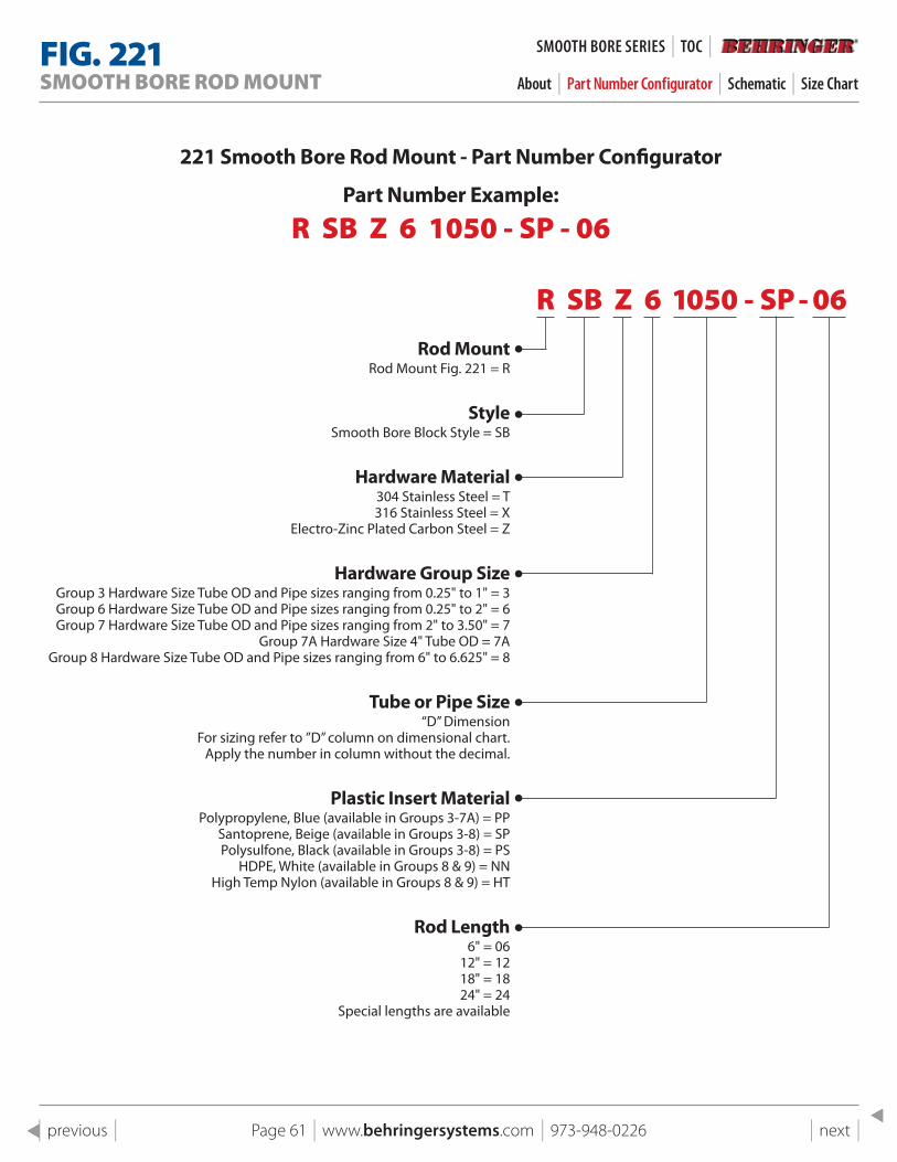
221 smooth Bore Rod Mount - part Number Configurator
part Number Example:
R SB Z 6 1050 - SP - 06
R SB Z 6 1050 - SP - 06Rod Mount
Rod Mount Fig. 221 = R
styleSmooth Bore Block Style = SB
Hardware Material304 Stainless Steel = T 316 Stainless Steel = X
Electro-Zinc Plated Carbon Steel = Z
Hardware Group sizeGroup 3 Hardware Size Tube OD and Pipe sizes ranging from 0.25" to 1" = 3 Group 6 Hardware Size Tube OD and Pipe sizes ranging from 0.25" to 2" = 6 Group 7 Hardware Size Tube OD and Pipe sizes ranging from 2" to 3.50" = 7
Group 7A Hardware Size 4" Tube OD = 7AGroup 8 Hardware Size Tube OD and Pipe sizes ranging from 6" to 6.625" = 8
Tube or pipe size“D” Dimension
For sizing refer to ”D” column on dimensional chart.Apply the number in column without the decimal.
plastic Insert Material Polypropylene, Blue (available in Groups 3-7A) = PP
Santoprene, Beige (available in Groups 3-8) = SP Polysulfone, Black (available in Groups 3-8) = PS
HDPE, White (available in Groups 8 & 9) = NN High Temp Nylon (available in Groups 8 & 9) = HT
Rod length6" = 06
12" = 1218" = 1824" = 24
Special lengths are available
FIG . 221SMOOTH BORE ROD MOUNT About | Part Number Configurator | Schematic | Size Chart
SMOOTH BORe SeRIeS | TOC |
Page 62 | www.behringersystems.com | 973-948-0226 | next | | previous |
1
1
2
2
3
3
4
4
A A
B B
C C
D D
SHEET 1 OF 1
DRAWN
CHECKED
QA
MFG
APPROVED
11/4/2018
DWG NO
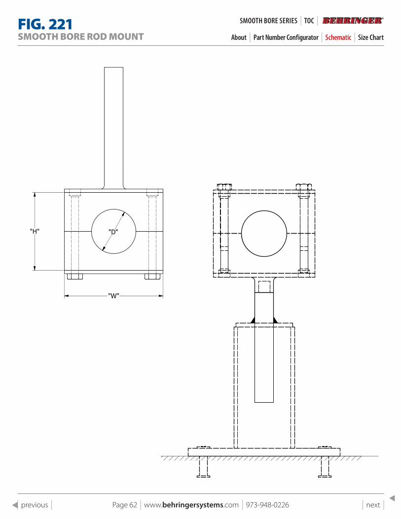
221 Smooth Bore Rod Mount
TITLE
Fig 221 Hang Plate Smooth Bore Rod Mount
SIZE
CSCALE
REV
"D"
"W"
"H"
FIG . 221SMOOTH BORE ROD MOUNT About | Part Number Configurator | Schematic | Size Chart
SMOOTH BORe SeRIeS | TOC |
Page 63 | www.behringersystems.com | 973-948-0226 | next | | previous |
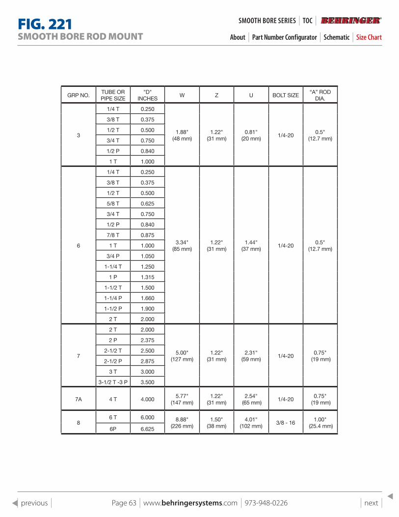
GRP NO.TUBE OR PIPE SIZE
"D" INCHES
W Z U BOLT SIZE“A” ROD
DIA.
3
1/4 T 0.250
1.88" (48 mm)
1.22" (31 mm)
0.81" (20 mm)
1/4-200.5"
(12.7 mm)
3/8 T 0.375
1/2 T 0.500
3/4 T 0.750
1/2 P 0.840
1 T 1.000
6
1/4 T 0.250
3.34" (85 mm)
1.22" (31 mm)
1.44" (37 mm)
1/4-200.5"
(12.7 mm)
3/8 T 0.375
1/2 T 0.500
5/8 T 0.625
3/4 T 0.750
1/2 P 0.840
7/8 T 0.875
1 T 1.000
3/4 P 1.050
1-1/4 T 1.250
1 P 1.315
1-1/2 T 1.500
1-1/4 P 1.660
1-1/2 P 1.900
2 T 2.000
7
2 T 2.000
5.00" (127 mm)
1.22" (31 mm)
2.31" (59 mm)
1/4-200.75"
(19 mm)
2 P 2.375
2-1/2 T 2.500
2-1/2 P 2.875
3 T 3.000
3-1/2 T -3 P 3.500
7A 4 T 4.0005.77"
(147 mm)1.22"
(31 mm)2.54"
(65 mm)1/4-20
0.75" (19 mm)
86 T 6.000 8.88"
(226 mm)1.50"
(38 mm) 4.01"
(102 mm)3/8 - 16
1.00" (25.4 mm)6P 6.625
FIG . 221SMOOTH BORE ROD MOUNT About | Part Number Configurator | Schematic | Size Chart
SMOOTH BORe SeRIeS | TOC |
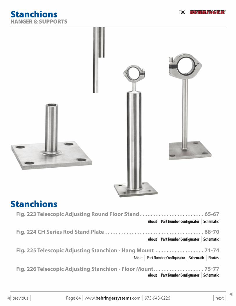
StanchionsHANGER & SUPPORTS
StanchionsFig . 223 Telescopic Adjusting Round Floor stand . . . . . . . . . . . . . . . . . . . . . . . . 65-67
About | Part Number Configurator | Schematic
Fig . 224 CH series Rod stand plate . . . . . . . . . . . . . . . . . . . . . . . . . . . . . . . . . . . . . 68-70About | Part Number Configurator | Schematic
Fig . 225 Telescopic Adjusting stanchion - Hang Mount . . . . . . . . . . . . . . . . . . 71-74About | Part Number Configurator | Schematic | Photos
Fig . 226 Telescopic Adjusting stanchion - Floor Mount . . . . . . . . . . . . . . . . . . . 75-77About | Part Number Configurator | Schematic
TOC |
Page 64 | www.behringersystems.com | 973-948-0226 | next | | previous |
Page 65 | www.behringersystems.com | 973-948-0226 | next | | previous |
FIG . 223TELESCOPIC ADJUSTING ROUND FLOOR MOUNT STAND
About | Part Number Configurator | Schematic
STANCHIONS | TOC |
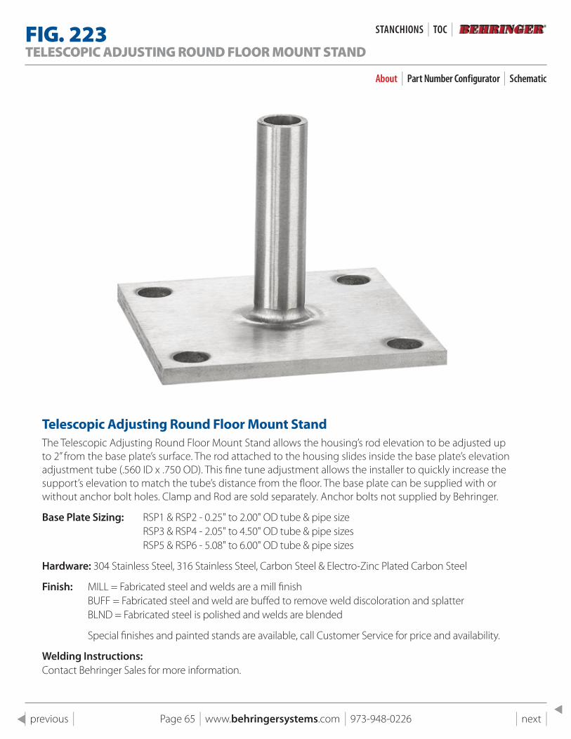
Telescopic Adjusting Round Floor Mount standThe Telescopic Adjusting Round Floor Mount Stand allows the housing’s rod elevation to be adjusted up to 2” from the base plate’s surface. The rod attached to the housing slides inside the base plate’s elevation adjustment tube (.560 ID x .750 OD). This fine tune adjustment allows the installer to quickly increase the support’s elevation to match the tube’s distance from the floor. The base plate can be supplied with or without anchor bolt holes. Clamp and Rod are sold separately. Anchor bolts not supplied by Behringer.
Base Plate Sizing: RSP1 & RSP2 - 0.25" to 2.00" OD tube & pipe size RSP3 & RSP4 - 2.05" to 4.50" OD tube & pipe sizes RSP5 & RSP6 - 5.08" to 6.00" OD tube & pipe sizes
Hardware: 304 Stainless Steel, 316 Stainless Steel, Carbon Steel & Electro-Zinc Plated Carbon Steel
Finish: MILL = Fabricated steel and welds are a mill finish BUFF = Fabricated steel and weld are buffed to remove weld discoloration and splatter BLND = Fabricated steel is polished and welds are blended
Special finishes and painted stands are available, call Customer Service for price and availability.
Welding Instructions: Contact Behringer Sales for more information.
Page 66 | www.behringersystems.com | 973-948-0226 | next | | previous |
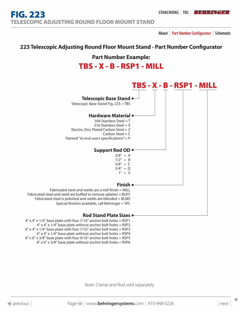
Note: Clamp and Rod sold separately
223 Telescopic Adjusting Round Floor Mount stand - part Number Configurator
part Number Example:
TBS - X - B - RSP1 - MILL
TBS - X - B - RSP1 - MILLTelescopic Base stand
Telescopic Base Stand Fig. 223 = TBS
Hardware Material304 Stainless Steel = T 316 Stainless Steel = X
Electro-Zinc Plated Carbon Steel = ZCarbon Steel = C
Painted “to end users specifications” = P
support Rod OD 3/8" = A 1/2" = B 5/8" = C 3/4" = D 1" = E
Finish Fabricated steel and welds are a mill finish = MILL
Fabricated steel and weld are buffed to remove splatter = BUFF Fabricated steel is polished and welds are blended = BLND
Special finishes available, call Behringer = SPL
Rod stand plate sizes 4" x 4" x 1/4" base plate with four 7/16" anchor bolt holes = RSP1
4" x 4" x 1/4" base plate without anchor bolt holes = RSP2 6" x 4" x 1/4" base plate with four 7/16" anchor bolt holes = RSP3
6" x 4" x 1/4" base plate without anchor bolt holes = RSP4 8" x 6" x 3/8" base plate with four 9/16" anchor bolt holes = RSP5
8" x 6" x 3/8" base plate without anchor bolt holes = RSP6
FIG . 223TELESCOPIC ADJUSTING ROUND FLOOR MOUNT STAND
About | Part Number Configurator | Schematic
STANCHIONS | TOC |
Page 67 | www.behringersystems.com | 973-948-0226 | next | | previous |
1
1
2
2
3
3
4
4
A A
B B
C C
D D
SHEET 1 OF 1
DRAWN
CHECKED
QA
MFG
APPROVED
11/4/2018
DWG NO
223 pg 13 Assembly
TITLE
Fig 223 Telescope Adjusting Floor Mount Stand
SIZE
CSCALE
REV
"U"
"L" = 3.0
1.000 TYP.
1.000 TYP.
(4) Holes, (TYP.)For Hole Dia. Referto Part NumberConfigurator
Support Rod O.D.
1
1
2
2
3
3
4
4
A A
B B
C C
D D
SHEET 1 OF 1
DRAWN
CHECKED
QA
MFG
APPROVED
11/4/2018
DWG NO
223 pg 13 Stub & Base Assembly
TITLE
Fig 223 Stub & Base
SIZE
CSCALE
REV
Base
Tube Support
1
1
2
2
3
3
4
4
A A
B B
C C
D D
SHEET 1 OF 1
DRAWN
CHECKED
QA
MFG
APPROVED
11/4/2018
DWG NO
223 pg 13 Stub & Base Assembly
TITLE
Fig 223 Stub & Base
SIZE
CSCALE
REV
"X" Tube Support I.D.
"L"
Base Plate
FIG . 223TELESCOPIC ADJUSTING ROUND FLOOR MOUNT STAND
About | Part Number Configurator | Schematic
STANCHIONS | TOC |
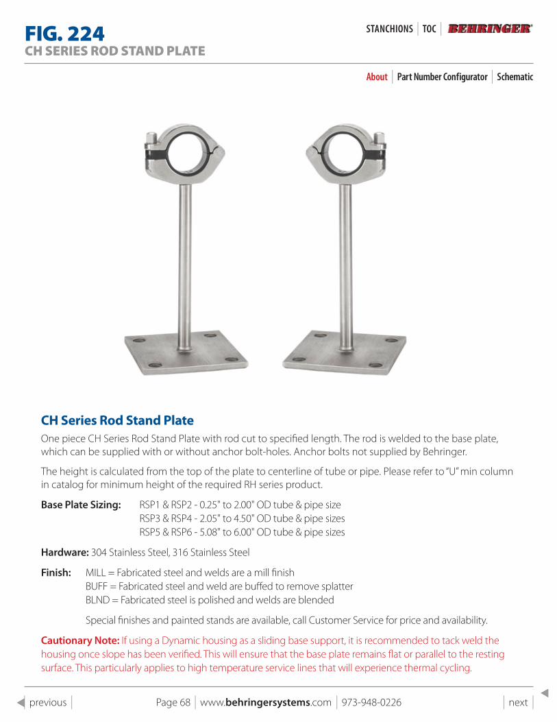
Page 68 | www.behringersystems.com | 973-948-0226 | next | | previous |
FIG . 224CH SERIES ROD STAND PLATE
About | Part Number Configurator | Schematic
CH series Rod stand plateOne piece CH Series Rod Stand Plate with rod cut to specified length. The rod is welded to the base plate, which can be supplied with or without anchor bolt-holes. Anchor bolts not supplied by Behringer.
The height is calculated from the top of the plate to centerline of tube or pipe. Please refer to “U” min column in catalog for minimum height of the required RH series product.
Base Plate Sizing: RSP1 & RSP2 - 0.25" to 2.00" OD tube & pipe size RSP3 & RSP4 - 2.05" to 4.50" OD tube & pipe sizes RSP5 & RSP6 - 5.08" to 6.00" OD tube & pipe sizes
Hardware: 304 Stainless Steel, 316 Stainless Steel
Finish: MILL = Fabricated steel and welds are a mill finish BUFF = Fabricated steel and weld are buffed to remove splatter BLND = Fabricated steel is polished and welds are blended
Special finishes and painted stands are available, call Customer Service for price and availability.
Cautionary Note: If using a Dynamic housing as a sliding base support, it is recommended to tack weld the housing once slope has been verified. This will ensure that the base plate remains flat or parallel to the resting surface. This particularly applies to high temperature service lines that will experience thermal cycling.
STANCHIONS | TOC |
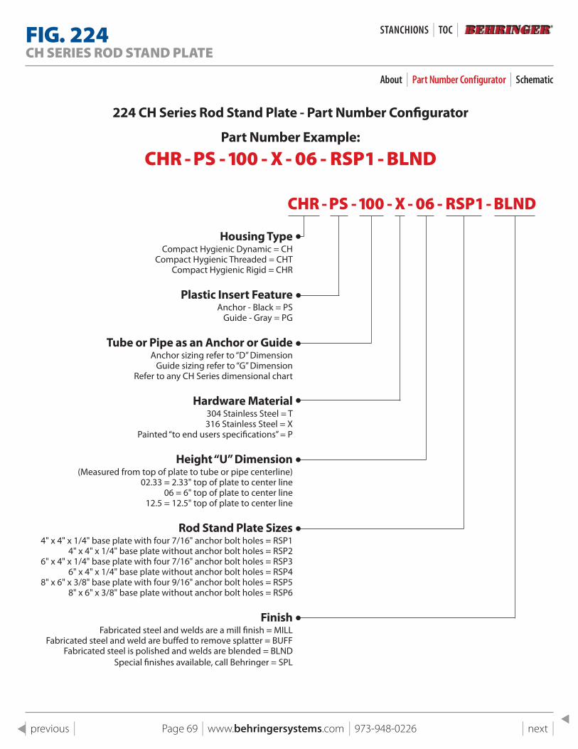
Page 69 | www.behringersystems.com | 973-948-0226 | next | | previous |
224 CH series Rod stand plate - part Number Configurator
part Number Example:
CHR - PS - 100 - X - 06 - RSP1 - BLND
CHR - PS - 100 - X - 06 - RSP1 - BLND
Housing TypeCompact Hygienic Dynamic = CH
Compact Hygienic Threaded = CHTCompact Hygienic Rigid = CHR
plastic Insert FeatureAnchor - Black = PS
Guide - Gray = PG
Tube or pipe as an Anchor or GuideAnchor sizing refer to “D” Dimension
Guide sizing refer to “G” DimensionRefer to any CH Series dimensional chart
Hardware Material304 Stainless Steel = T 316 Stainless Steel = X
Painted “to end users specifications” = P
Height “U” Dimension (Measured from top of plate to tube or pipe centerline) 02.33 = 2.33" top of plate to center line
06 = 6" top of plate to center line12.5 = 12.5" top of plate to center line
Rod stand plate sizes 4" x 4" x 1/4" base plate with four 7/16" anchor bolt holes = RSP1
4" x 4" x 1/4" base plate without anchor bolt holes = RSP2 6" x 4" x 1/4" base plate with four 7/16" anchor bolt holes = RSP3
6" x 4" x 1/4" base plate without anchor bolt holes = RSP4 8" x 6" x 3/8" base plate with four 9/16" anchor bolt holes = RSP5
8" x 6" x 3/8" base plate without anchor bolt holes = RSP6
Finish Fabricated steel and welds are a mill finish = MILL
Fabricated steel and weld are buffed to remove splatter = BUFF Fabricated steel is polished and welds are blended = BLND
Special finishes available, call Behringer = SPL
FIG . 224CH SERIES ROD STAND PLATE
About | Part Number Configurator | Schematic
STANCHIONS | TOC |
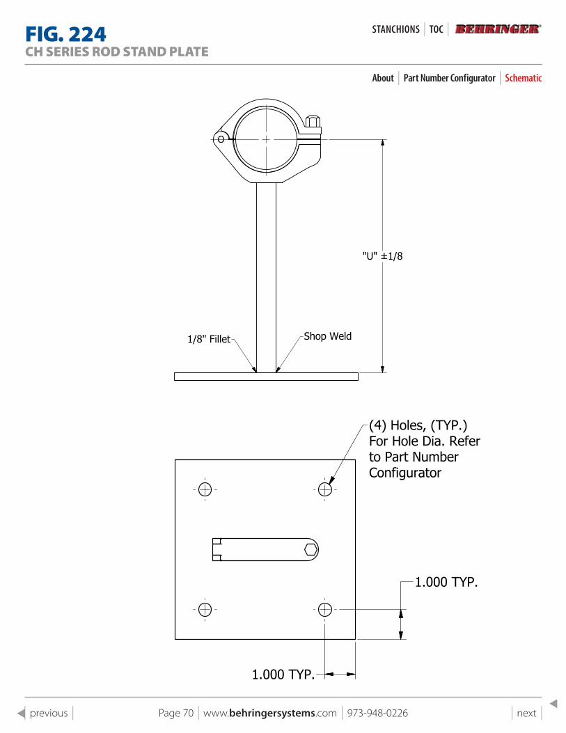
Page 70 | www.behringersystems.com | 973-948-0226 | next | | previous |
1
1
2
2
3
3
4
4
A A
B B
C C
D D
SHEET 1 OF 1
DRAWN
CHECKED
QA
MFG
APPROVED
11/4/2018
DWG NO
224 pg 14 Assembly
TITLE
Fig 224 CH Series Rod Stand Plate
SIZE
CSCALE
REV
"U" ±1/8
Shop Weld1/8" Fillet
1.000 TYP.
1.000 TYP.
(4) Holes, (TYP.)For Hole Dia. Referto Part NumberConfigurator
1
1
2
2
3
3
4
4
A A
B B
C C
D D
SHEET 1 OF 1
DRAWN
CHECKED
QA
MFG
APPROVED
11/4/2018
DWG NO
224 pg 14 Assembly
TITLE
Fig 224 CH Series Rod Stand Plate
SIZE
CSCALE
REV
"U" ±1/8
Shop Weld1/8" Fillet
1.000 TYP.
1.000 TYP.
(4) Holes, (TYP.)For Hole Dia. Referto Part NumberConfigurator
1
1
2
2
3
3
4
4
A A
B B
C C
D D
SHEET 1 OF 1
DRAWN
CHECKED
QA
MFG
APPROVED
11/4/2018
DWG NO
224 pg 14 Assembly
TITLE
Fig 224 CH Series Rod Stand Plate
SIZE
CSCALE
REV
"U" ±1/8
Shop Weld1/8" Fillet
1.000 TYP.
1.000 TYP.
(4) Holes, (TYP.)For Hole Dia. Referto Part NumberConfigurator
FIG . 224CH SERIES ROD STAND PLATE
About | Part Number Configurator | Schematic
STANCHIONS | TOC |
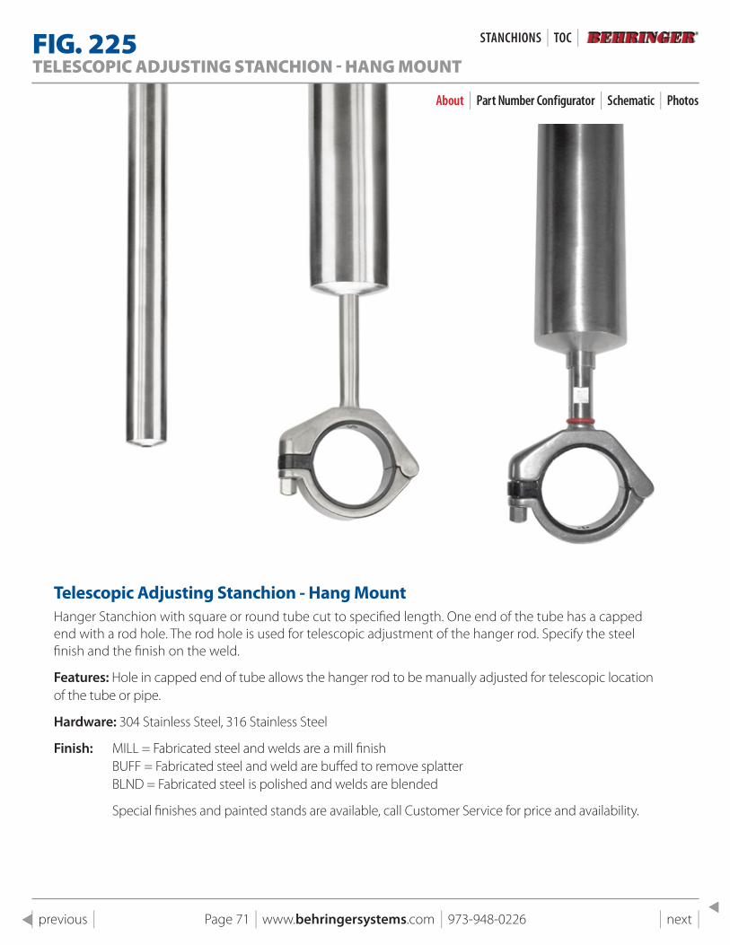
Page 71 | www.behringersystems.com | 973-948-0226 | next | | previous |
FIG . 225TELESCOPIC ADJUSTING STANCHION - HANG MOUNT
About | Part Number Configurator | Schematic | Photos
Telescopic Adjusting stanchion - Hang MountHanger Stanchion with square or round tube cut to specified length. One end of the tube has a capped end with a rod hole. The rod hole is used for telescopic adjustment of the hanger rod. Specify the steel finish and the finish on the weld.
Features: Hole in capped end of tube allows the hanger rod to be manually adjusted for telescopic location of the tube or pipe.
Hardware: 304 Stainless Steel, 316 Stainless Steel
Finish: MILL = Fabricated steel and welds are a mill finish BUFF = Fabricated steel and weld are buffed to remove splatter BLND = Fabricated steel is polished and welds are blended
Special finishes and painted stands are available, call Customer Service for price and availability.
STANCHIONS | TOC |
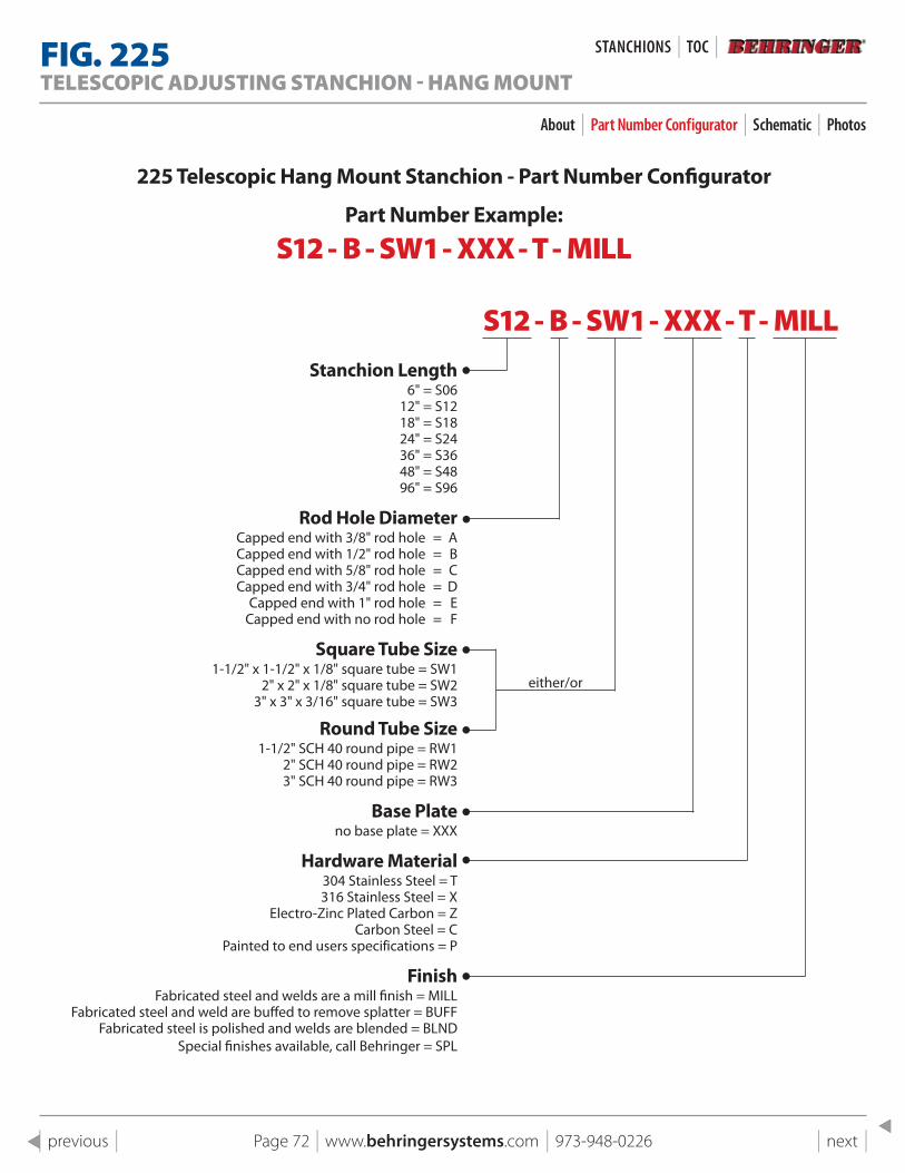
Page 72 | www.behringersystems.com | 973-948-0226 | next | | previous |
225 Telescopic Hang Mount stanchion - part Number Configurator
part Number Example:
S12 - B - SW1 - XXX - T - MILL
S12 - B - SW1 - XXX - T - MILLstanchion length
6" = S0612" = S1218" = S1824" = S2436" = S3648" = S4896" = S96
Rod Hole Diameter Capped end with 3/8" rod hole = A Capped end with 1/2" rod hole = B Capped end with 5/8" rod hole = C Capped end with 3/4" rod hole = D Capped end with 1" rod hole = E Capped end with no rod hole = F
square Tube size1-1/2" x 1-1/2" x 1/8" square tube = SW1
2" x 2" x 1/8" square tube = SW23" x 3" x 3/16" square tube = SW3
Round Tube size1-1/2" SCH 40 round pipe = RW1
2" SCH 40 round pipe = RW23" SCH 40 round pipe = RW3
Base plateno base plate = XXX
Hardware Material304 Stainless Steel = T 316 Stainless Steel = X
Electro-Zinc Plated Carbon = ZCarbon Steel = C
Painted to end users specifications = P
Finish Fabricated steel and welds are a mill finish = MILL
Fabricated steel and weld are buffed to remove splatter = BUFF Fabricated steel is polished and welds are blended = BLND
Special finishes available, call Behringer = SPL
either/or
FIG . 225TELESCOPIC ADJUSTING STANCHION - HANG MOUNT
About | Part Number Configurator | Schematic | Photos
STANCHIONS | TOC |
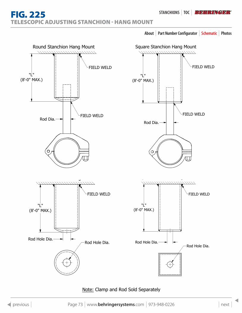
Page 73 | www.behringersystems.com | 973-948-0226 | next | | previous |
1
1
2
2
3
3
4
4
A A
B B
C C
D D
SHEET 1 OF 1
DRAWN
CHECKED
QA
MFG
APPROVED
11/4/2018
DWG NO
225 pg 15 Assembly Round Top
TITLE
Fig 225 Telescopic Adjusting Stanchion - Hang Mount
SIZE
CSCALE
REV
"L"(8'-0" MAX.)
FIELD WELD
Round Stanchion Hang Mount
Round Stanchion Hang Mount
FIELD WELD
Rod Hole Dia.
Rod Dia.
Rod Hole Dia.
Note: Clamp and Rod Sold Separately
Rod Hole Dia.
"L"(8'-0" MAX.)
"L"(8'-0" MAX.)
FIELD WELD
1
1
2
2
3
3
4
4
A A
B B
C C
D D
SHEET 1 OF 1
DRAWN
CHECKED
QA
MFG
APPROVED
11/4/2018
DWG NO
225 pg 15 Assembly
TITLE
Fig 225 Telescopic Adjusting Stanchion - Hang Mount
SIZE
CSCALE
REV
"L"(8'-0" MAX.)
FIELD WELD
Square Stanchion Hang Mount
Square Stanchion Hang Mount
FIELD WELD
"L"(8'-0" MAX.)
FIELD WELD
Rod Hole Dia.
Rod Dia.
Rod Hole Dia.
Note: Clamp and Rod Sold Separately
1
1
2
2
3
3
4
4
A A
B B
C C
D D
SHEET 1 OF 1
DRAWN
CHECKED
QA
MFG
APPROVED
11/4/2018
DWG NO
225 pg 15 Assembly Round Top
TITLE
Fig 225 Telescopic Adjusting Stanchion - Hang Mount
SIZE
CSCALE
REV
"L"(8'-0" MAX.)
FIELD WELD
Round Stanchion Hang Mount
Round Stanchion Hang Mount
FIELD WELD
Rod Hole Dia.
Rod Dia.
Rod Hole Dia.
Note: Clamp and Rod Sold Separately
Rod Hole Dia.
"L"(8'-0" MAX.)
"L"(8'-0" MAX.)
FIELD WELD
1
1
2
2
3
3
4
4
A A
B B
C C
D D
SHEET 1 OF 1
DRAWN
CHECKED
QA
MFG
APPROVED
11/4/2018
DWG NO
225 pg 15 Assembly
TITLE
Fig 225 Telescopic Adjusting Stanchion - Hang Mount
SIZE
CSCALE
REV
"L"(8'-0" MAX.)
FIELD WELD
Square Stanchion Hang Mount
Square Stanchion Hang Mount
FIELD WELD
"L"(8'-0" MAX.)
FIELD WELD
Rod Hole Dia.
Rod Dia.
Rod Hole Dia.
Note: Clamp and Rod Sold Separately
FIG . 225TELESCOPIC ADJUSTING STANCHION - HANG MOUNT
About | Part Number Configurator | Schematic | Photos
STANCHIONS | TOC |
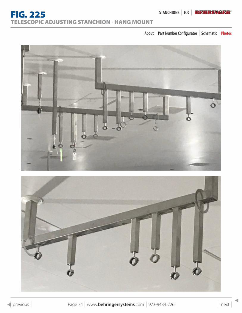
Page 74 | www.behringersystems.com | 973-948-0226 | next | | previous |
FIG . 225TELESCOPIC ADJUSTING STANCHION - HANG MOUNT
About | Part Number Configurator | Schematic | Photos
STANCHIONS | TOC |
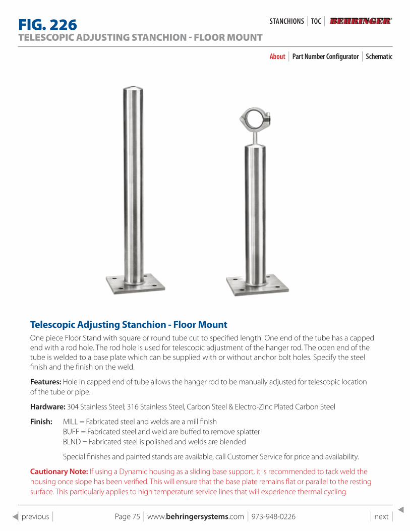
Page 75 | www.behringersystems.com | 973-948-0226 | next | | previous |
FIG . 226TELESCOPIC ADJUSTING STANCHION - FLOOR MOUNT
About | Part Number Configurator | Schematic
Telescopic Adjusting stanchion - Floor MountOne piece Floor Stand with square or round tube cut to specified length. One end of the tube has a capped end with a rod hole. The rod hole is used for telescopic adjustment of the hanger rod. The open end of the tube is welded to a base plate which can be supplied with or without anchor bolt holes. Specify the steel finish and the finish on the weld.
Features: Hole in capped end of tube allows the hanger rod to be manually adjusted for telescopic location of the tube or pipe.
Hardware: 304 Stainless Steel; 316 Stainless Steel, Carbon Steel & Electro-Zinc Plated Carbon Steel
Finish: MILL = Fabricated steel and welds are a mill finish BUFF = Fabricated steel and weld are buffed to remove splatter BLND = Fabricated steel is polished and welds are blended
Special finishes and painted stands are available, call Customer Service for price and availability.
Cautionary Note: If using a Dynamic housing as a sliding base support, it is recommended to tack weld the housing once slope has been verified. This will ensure that the base plate remains flat or parallel to the resting surface. This particularly applies to high temperature service lines that will experience thermal cycling.
STANCHIONS | TOC |
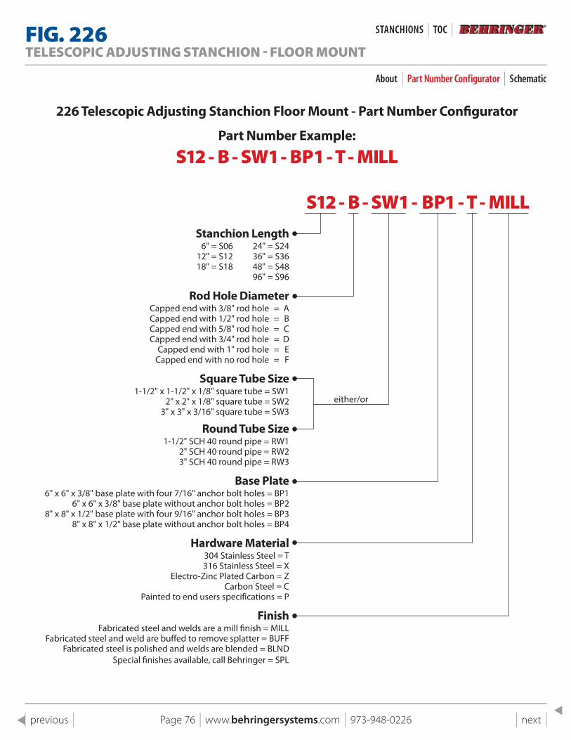
Page 76 | www.behringersystems.com | 973-948-0226 | next | | previous |
226 Telescopic Adjusting stanchion Floor Mount - part Number Configurator
part Number Example:
S12 - B - SW1 - BP1 - T - MILL
S12 - B - SW1 - BP1 - T - MILLstanchion length
6" = S06 24" = S2412" = S12 36" = S3618" = S18 48" = S48
96" = S96
Rod Hole Diameter Capped end with 3/8" rod hole = A Capped end with 1/2" rod hole = B Capped end with 5/8" rod hole = C Capped end with 3/4" rod hole = D Capped end with 1" rod hole = E Capped end with no rod hole = F
square Tube size1-1/2" x 1-1/2" x 1/8" square tube = SW1
2" x 2" x 1/8" square tube = SW23" x 3" x 3/16" square tube = SW3
Round Tube size1-1/2" SCH 40 round pipe = RW1
2" SCH 40 round pipe = RW23" SCH 40 round pipe = RW3
Base plate 6" x 6" x 3/8" base plate with four 7/16" anchor bolt holes = BP1
6" x 6" x 3/8" base plate without anchor bolt holes = BP2 8" x 8" x 1/2" base plate with four 9/16" anchor bolt holes = BP3
8" x 8" x 1/2" base plate without anchor bolt holes = BP4
Hardware Material304 Stainless Steel = T 316 Stainless Steel = X
Electro-Zinc Plated Carbon = ZCarbon Steel = C
Painted to end users specifications = P
Finish Fabricated steel and welds are a mill finish = MILL
Fabricated steel and weld are buffed to remove splatter = BUFF Fabricated steel is polished and welds are blended = BLND
Special finishes available, call Behringer = SPL
either/or
FIG . 226TELESCOPIC ADJUSTING STANCHION - FLOOR MOUNT
About | Part Number Configurator | Schematic
STANCHIONS | TOC |
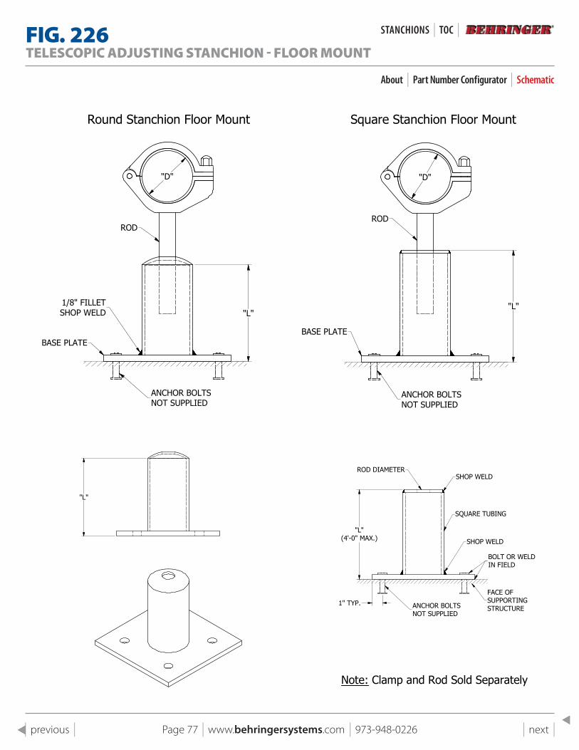
Page 77 | www.behringersystems.com | 973-948-0226 | next | | previous |
1
1
2
2
3
3
4
4
A A
B B
C C
D D
SHEET 1 OF 1
DRAWN
CHECKED
QA
MFG
APPROVED
11/4/2018
DWG NO
226 pg 16 Assembly Square Assembly
TITLE
Fig 226 Telescopic Adjusting Stanchion - Square Floor Mount
SIZE
CSCALE
REV
Square Stanchion Floor MountSquare Stanchion Floor Mount
"L"(4'-0" MAX.)
1" TYP.
ROD DIAMETERSHOP WELD
SQUARE TUBING
SHOP WELD
BOLT OR WELDIN FIELD
ANCHOR BOLTSNOT SUPPLIED
FACE OFSUPPORTINGSTRUCTURE
ROD
"L"
BASE PLATE
ANCHOR BOLTSNOT SUPPLIED
"D"
1
1
2
2
3
3
4
4
A A
B B
C C
D D
SHEET 1 OF 1
DRAWN
CHECKED
QA
MFG
APPROVED
11/4/2018
DWG NO
226 pg 16 Assembly
TITLE
Fig 226 Telescopic Adjusting Stanchion - Floor Mount
SIZE
CSCALE
REV
Square Stanchion Floor MountRound Stanchion Floor Mount
"L"
"D"
ROD
BASE PLATE
1/8" FILLETSHOP WELD
ANCHOR BOLTSNOT SUPPLIED
"L"(4'-0" MAX.)
1" TYP.
ROD DIAMETERSHOP WELD
SQUARE TUBING
SHOP WELD
BOLT OR WELDIN FIELD
ANCHOR BOLTSNOT SUPPLIED
FACE OFSUPPORTINGSTRUCTURE
1
1
2
2
3
3
4
4
A A
B B
C C
D D
SHEET 1 OF 1
DRAWN
CHECKED
QA
MFG
APPROVED
11/4/2018
DWG NO
226 pg 16 Assembly base plate wpipe only
TITLE
Fig 226 Telescopic Adjusting Stanchion - Floor Mount, Plate & Pipe Only
SIZE
CSCALE
REV
"L"
1
1
2
2
3
3
4
4
A A
B B
C C
D D
SHEET 1 OF 1
DRAWN
CHECKED
QA
MFG
APPROVED
11/4/2018
DWG NO
226 pg 16 Assembly base plate wpipe only
TITLE
Fig 226 Telescopic Adjusting Stanchion - Floor Mount, Plate & Pipe Only
SIZE
CSCALE
REV
"L"
1
1
2
2
3
3
4
4
A A
B B
C C
D D
SHEET 1 OF 1
DRAWN
CHECKED
QA
MFG
APPROVED
11/4/2018
DWG NO
225 pg 15 Assembly Round Top
TITLE
Fig 225 Telescopic Adjusting Stanchion - Hang Mount
SIZE
CSCALE
REV
"L"(8'-0" MAX.)
FIELD WELD
Round Stanchion Hang Mount
Round Stanchion Hang Mount
FIELD WELD
Rod Hole Dia.
Rod Dia.
Rod Hole Dia.
Note: Clamp and Rod Sold Separately
Rod Hole Dia.
"L"(8'-0" MAX.)
"L"(8'-0" MAX.)
FIELD WELD
FIG . 226TELESCOPIC ADJUSTING STANCHION - FLOOR MOUNT
About | Part Number Configurator | Schematic
STANCHIONS | TOC |
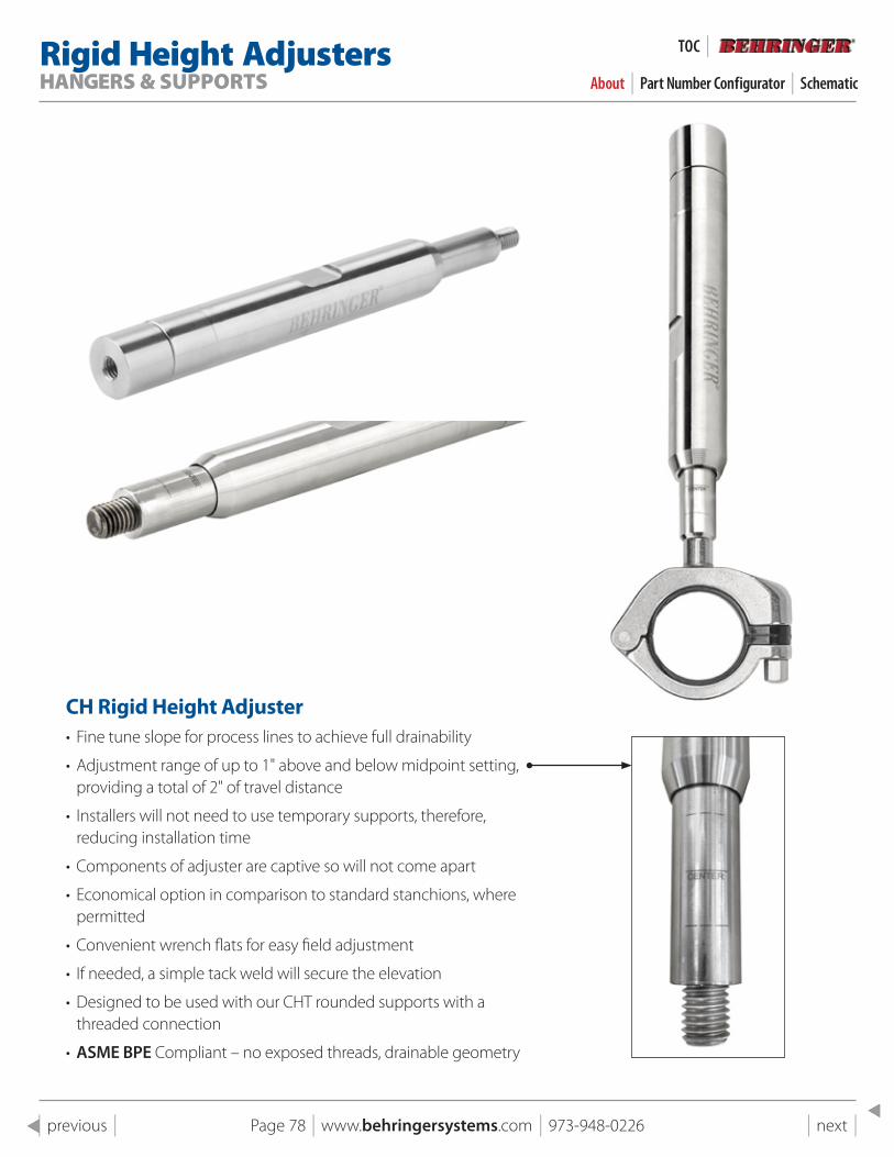
Rigid Height AdjustersHANGERS & SUPPORTS About | Part Number Configurator | Schematic
TOC |
Page 78 | www.behringersystems.com | 973-948-0226 | next | | previous |
CH Rigid Height Adjuster• Fine tune slope for process lines to achieve full drainability
• Adjustment range of up to 1" above and below midpoint setting, providing a total of 2" of travel distance
• Installers will not need to use temporary supports, therefore, reducing installation time
• Components of adjuster are captive so will not come apart
• Economical option in comparison to standard stanchions, where permitted
• Convenient wrench flats for easy field adjustment
• If needed, a simple tack weld will secure the elevation
• Designed to be used with our CHT rounded supports with a threaded connection
• ASME BPE Compliant – no exposed threads, drainable geometry
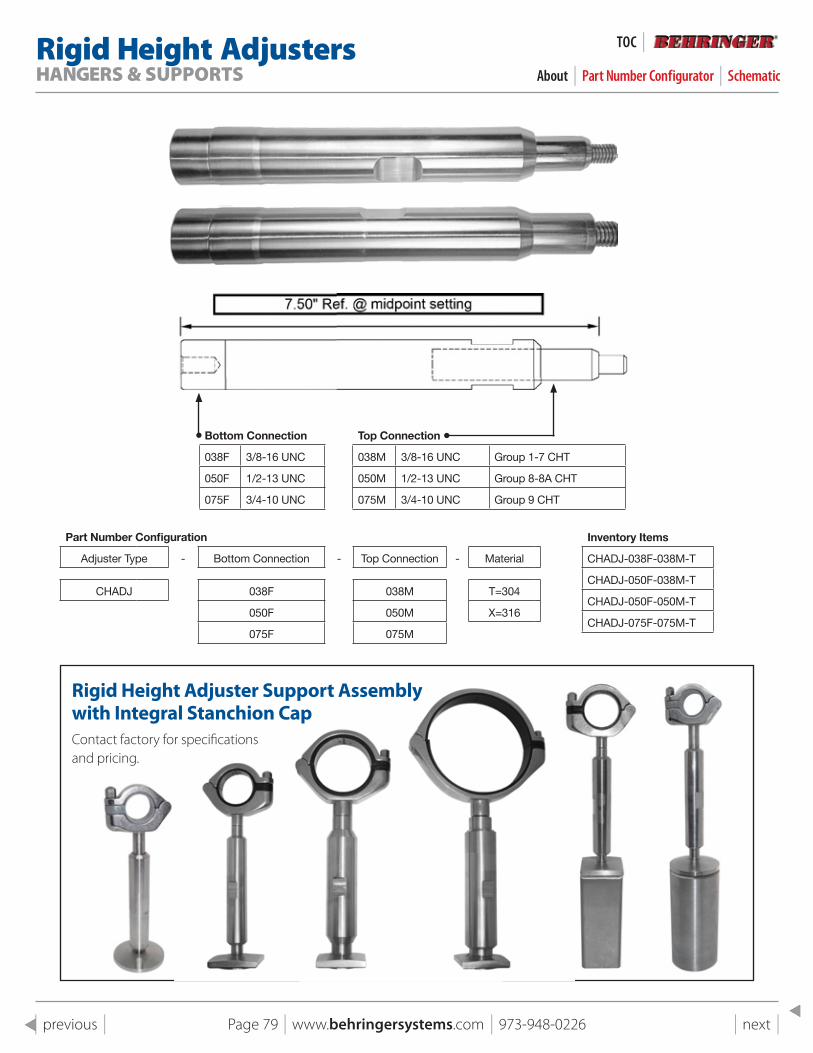
Page 79 | www.behringersystems.com | 973-948-0226 | next | | previous |
Bottom Connection Top Connection
038F 3/8-16 UNC 038M 3/8-16 UNC Group 1-7 CHT
050F 1/2-13 UNC 050M 1/2-13 UNC Group 8-8A CHT
075F 3/4-10 UNC 075M 3/4-10 UNC Group 9 CHT
Inventory Items
CHADJ-038F-038M-T
CHADJ-050F-038M-T
CHADJ-050F-050M-T
CHADJ-075F-075M-T
Part Number Configuration
Adjuster Type - Bottom Connection - Top Connection - Material
CHADJ 038F 038M T=304
050F 050M X=316
075F 075M
Rigid Height AdjustersHANGERS & SUPPORTS About | Part Number Configurator | Schematic
TOC |
Rigid Height Adjuster support Assembly with Integral stanchion CapContact factory for specifications and pricing.

Page 80 | www.behringersystems.com | 973-948-0226 | next | | previous |
CH Dynamic Height Adjuster• Dynamic style offers both height and slope adjustment after installation
• Saves time on piping installation-No need to install temporary supports
• Fine tune slope for process lines to achieve full drainability
• 1-1/2" of total travel length (3/4" length of adjustment from mid-point setting)
• Assembly includes CH Dynamic housing
• Shorter offset dimension than standard CH Height Adjuster
• Economical option in comparison to standard stanchions, where permitted
• Wrench flats for easy adjustment adjacent to the tube support
• Internal O-Ring seal to keep out any fluids
• Captive design for safety
• ASME BPE Compliant-No exposed threads, drainable geometry
Dynamic Height AdjustersHANGERS & SUPPORTS About | Photos
TOC |

Page 81 | www.behringersystems.com | 973-948-0226 | next | | previous |
Dynamic Height AdjustersHANGERS & SUPPORTS About | Photos
TOC |
The Height Adjustment Coupling:This coupling is designed for fine tuning of the elevation on hangers to get the proper slope for drainability. It can be used in conjunction with our stanchions or by themselves. The hygienic design of this coupling incorporates an integral o-ring seal and has a travel length of ½ in. Socket weld connection (Size to suit).
Part Number: CH-HA-T-1
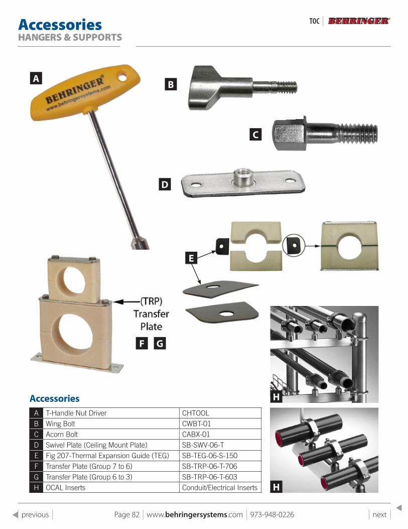
Page 82 | www.behringersystems.com | 973-948-0226 | next | | previous |
AccessoriesHANGERS & SUPPORTS
TOC |
AccessoriesA T-Handle Nut Driver CHTOOLB Wing Bolt CWBT-01C Acorn Bolt CABX-01D Swivel Plate (Ceiling Mount Plate) SB-SWV-06-TE Fig 207-Thermal Expansion Guide (TEG) SB-TEG-06-S-150F Transfer Plate (Group 7 to 6) SB-TRP-06-T-706G Transfer Plate (Group 6 to 3) SB-TRP-06-T-603H OCAL Inserts Conduit/Electrical Inserts
A B
C
D
F G
H
H
E
Technical AppendixHANGERS & SUPPORTS
TOC |
Page 83 | www.behringersystems.com | 973-948-0226 | next | | previous |
Technical Appendixproper slope for Drainability . . . . . . . . . . . . . . . . . . . . . . . . . . . . . . . . . . . . . . . . . . . . 84
Recommended Mounting practices . . . . . . . . . . . . . . . . . . . . . . . . . . . . . . . . . . . . . . 85
Thermal Expansion . . . . . . . . . . . . . . . . . . . . . . . . . . . . . . . . . . . . . . . . . . . . . . . . . . . . . 85
Material properties . . . . . . . . . . . . . . . . . . . . . . . . . . . . . . . . . . . . . . . . . . . . . . . . . . . . . 86
surface Finishing for Metal parts . . . . . . . . . . . . . . . . . . . . . . . . . . . . . . . . . . . . . . . . . 87
slope Conversion Chart . . . . . . . . . . . . . . . . . . . . . . . . . . . . . . . . . . . . . . . . . . . . . . . . . 88
shear Force Diagram . . . . . . . . . . . . . . . . . . . . . . . . . . . . . . . . . . . . . . . . . . . . . . . . . . . . 89
spacing of Hangers . . . . . . . . . . . . . . . . . . . . . . . . . . . . . . . . . . . . . . . . . . . . . . . . . . . . . 90
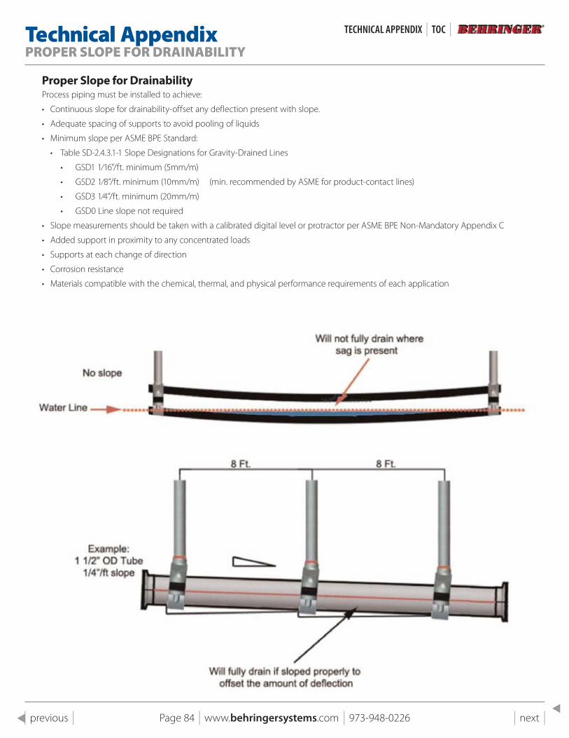
Page 84 | www.behringersystems.com | 973-948-0226 | next | | previous |
Technical AppendixPROPER SLOPE FOR DRAINABILITY
TeCHNICAL APPeNDIx | TOC |
proper slope for DrainabilityProcess piping must be installed to achieve:
• Continuous slope for drainability-offset any deflection present with slope.
• Adequate spacing of supports to avoid pooling of liquids
• Minimum slope per ASME BPE Standard:
• Table SD-2.4.3.1-1 Slope Designations for Gravity-Drained Lines
• GSD1 1⁄16”/ft. minimum (5mm/m)
• GSD2 1⁄8”/ft. minimum (10mm/m) (min. recommended by ASME for product-contact lines)
• GSD3 1⁄4”/ft. minimum (20mm/m)
• GSD0 Line slope not required
• Slope measurements should be taken with a calibrated digital level or protractor per ASME BPE Non-Mandatory Appendix C
• Added support in proximity to any concentrated loads
• Supports at each change of direction
• Corrosion resistance
• Materials compatible with the chemical, thermal, and physical performance requirements of each application
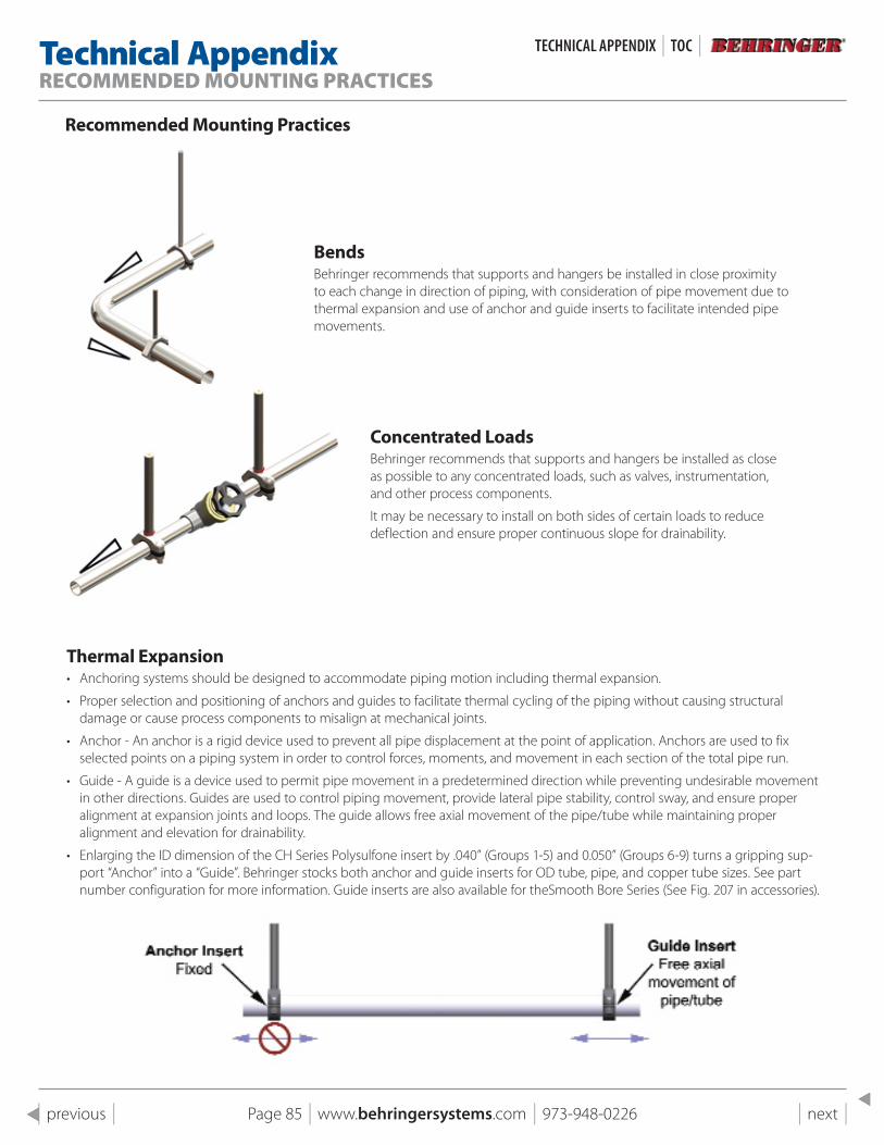
Page 85 | www.behringersystems.com | 973-948-0226 | next | | previous |
Technical AppendixRECOMMENDED MOUNTING PRACTICES
Recommended Mounting practices
BendsBehringer recommends that supports and hangers be installed in close proximity to each change in direction of piping, with consideration of pipe movement due to thermal expansion and use of anchor and guide inserts to facilitate intended pipe movements.
Concentrated LoadsBehringer recommends that supports and hangers be installed as close as possible to any concentrated loads, such as valves, instrumentation, and other process components.
It may be necessary to install on both sides of certain loads to reduce deflection and ensure proper continuous slope for drainability.
Thermal Expansion• Anchoring systems should be designed to accommodate piping motion including thermal expansion.
• Proper selection and positioning of anchors and guides to facilitate thermal cycling of the piping without causing structural damage or cause process components to misalign at mechanical joints.
• Anchor - An anchor is a rigid device used to prevent all pipe displacement at the point of application. Anchors are used to fix selected points on a piping system in order to control forces, moments, and movement in each section of the total pipe run.
• Guide - A guide is a device used to permit pipe movement in a predetermined direction while preventing undesirable movement in other directions. Guides are used to control piping movement, provide lateral pipe stability, control sway, and ensure proper alignment at expansion joints and loops. The guide allows free axial movement of the pipe/tube while maintaining proper alignment and elevation for drainability.
• Enlarging the ID dimension of the CH Series Polysulfone insert by .040” (Groups 1-5) and 0.050” (Groups 6-9) turns a gripping sup-port “Anchor” into a “Guide”. Behringer stocks both anchor and guide inserts for OD tube, pipe, and copper tube sizes. See part number configuration for more information. Guide inserts are also available for theSmooth Bore Series (See Fig. 207 in accessories).
TeCHNICAL APPeNDIx | TOC |
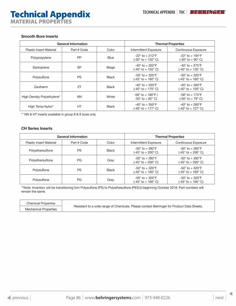
Page 86 | www.behringersystems.com | 973-948-0226 | next | | previous |
Technical AppendixMATERIAL PROPERTIES
Smooth Bore Inserts
General Information Thermal Properties
Plastic Insert Material Part # Code Color Intermittent Exposure Continuous Exposure
Polypropylene PP Blue-22° to + 212°F
(-30° to + 102° C)-22° to + 194°F(-30° to + 90° C)
Santoprene SP Beige-40° to + 302°F
(-40° to + 150° C)-40° to + 275°F
(-40° to + 135° C)
Polysulfone PS Black-50° to + 320°F
(-45° to + 160° C)-50° to + 320°F
(-45° to + 160° C)
Zeotherm ZT Black-40° to + 350°F
(-40° to + 175° C)-40° to + 300°F
(-40° to + 150° C)
High Density Polyethylene* NN White-58° to + 180°F (-50° to + 82° C)
-58° to + 175°F(-50° to + 79° C)
High Temp Nylon* HT Black-40° to + 350°F
(-40° to + 177° C)-40° to + 260°F
(-40° to + 127° C)
** NN & HT inserts available in group 8 & 9 sizes only
CH Series Inserts
General Information Thermal Properties
Plastic Insert Material Part # Code Color Intermittent Exposure Continuous Exposure
Polyethersulfone PS Black-50° to + 392°F
(-45° to + 200° C)-50° to + 392°F
(-45° to + 200° C)
Polyethersulfone PG Gray-50° to + 392°F
(-45° to + 200° C)-50° to + 392°F
(-45° to + 200° C)
Polysulfone PS Black-50° to + 320°F
(-45° to + 160° C)-50° to + 320°F
(-45° to + 160° C)
Polysulfone PG Gray-50° to + 320°F
(-45° to + 160° C)-50° to + 320°F
(-45° to + 160° C)
**Note: Inventory will be transitioning fom Polysulfone (PS) to Polyethesulfone (PESU) beginning October 2018. Part numbers will remain the same.
Chemical PropertiesResistant to a wide range of Chemicals. Please contact Behringer for Product Data Sheets.
Mechanical Properties
TeCHNICAL APPeNDIx | TOC |
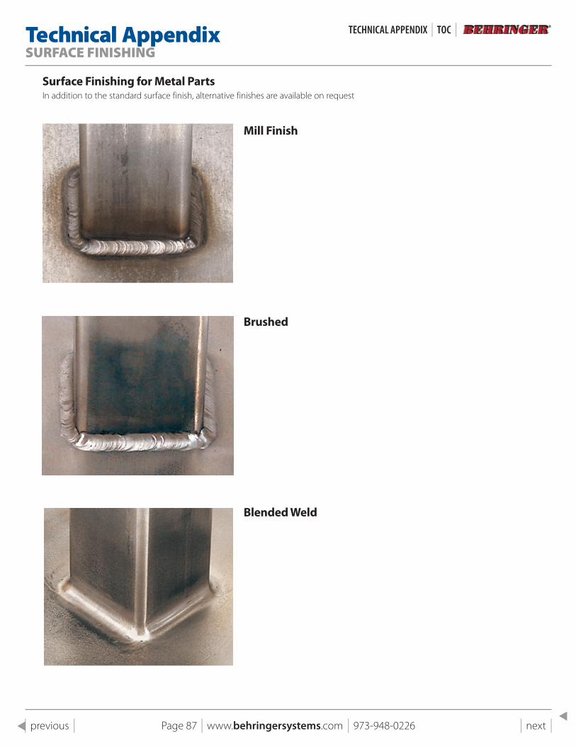
Page 87 | www.behringersystems.com | 973-948-0226 | next | | previous |
Technical AppendixSURFACE FINISHING
surface Finishing for Metal partsIn addition to the standard surface finish, alternative finishes are available on request
Mill Finish
Brushed
Blended Weld
TeCHNICAL APPeNDIx | TOC |
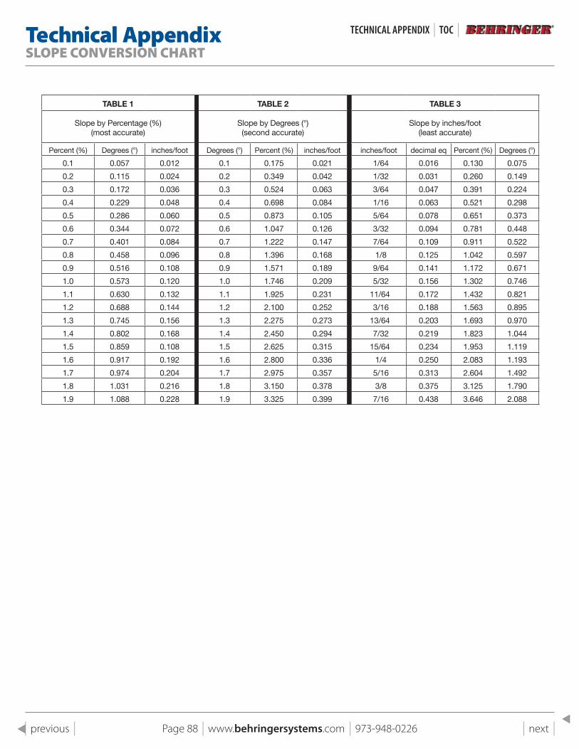
Page 88 | www.behringersystems.com | 973-948-0226 | next | | previous |
Technical AppendixSLOPE CONVERSION CHART
TaBle 1 TaBle 2 TaBle 3
Slope by Percentage (%)(most accurate)
Slope by Degrees (°)(second accurate)
Slope by inches/foot(least accurate)
Percent (%) Degrees (°) inches/foot Degrees (°) Percent (%) inches/foot inches/foot decimal eq Percent (%) Degrees (°)
0.1 0.057 0.012 0.1 0.175 0.021 1/64 0.016 0.130 0.075
0.2 0.115 0.024 0.2 0.349 0.042 1/32 0.031 0.260 0.149
0.3 0.172 0.036 0.3 0.524 0.063 3/64 0.047 0.391 0.224
0.4 0.229 0.048 0.4 0.698 0.084 1/16 0.063 0.521 0.298
0.5 0.286 0.060 0.5 0.873 0.105 5/64 0.078 0.651 0.373
0.6 0.344 0.072 0.6 1.047 0.126 3/32 0.094 0.781 0.448
0.7 0.401 0.084 0.7 1.222 0.147 7/64 0.109 0.911 0.522
0.8 0.458 0.096 0.8 1.396 0.168 1/8 0.125 1.042 0.597
0.9 0.516 0.108 0.9 1.571 0.189 9/64 0.141 1.172 0.671
1.0 0.573 0.120 1.0 1.746 0.209 5/32 0.156 1.302 0.746
1.1 0.630 0.132 1.1 1.925 0.231 11/64 0.172 1.432 0.821
1.2 0.688 0.144 1.2 2.100 0.252 3/16 0.188 1.563 0.895
1.3 0.745 0.156 1.3 2.275 0.273 13/64 0.203 1.693 0.970
1.4 0.802 0.168 1.4 2.450 0.294 7/32 0.219 1.823 1.044
1.5 0.859 0.108 1.5 2.625 0.315 15/64 0.234 1.953 1.119
1.6 0.917 0.192 1.6 2.800 0.336 1/4 0.250 2.083 1.193
1.7 0.974 0.204 1.7 2.975 0.357 5/16 0.313 2.604 1.492
1.8 1.031 0.216 1.8 3.150 0.378 3/8 0.375 3.125 1.790
1.9 1.088 0.228 1.9 3.325 0.399 7/16 0.438 3.646 2.088
TeCHNICAL APPeNDIx | TOC |
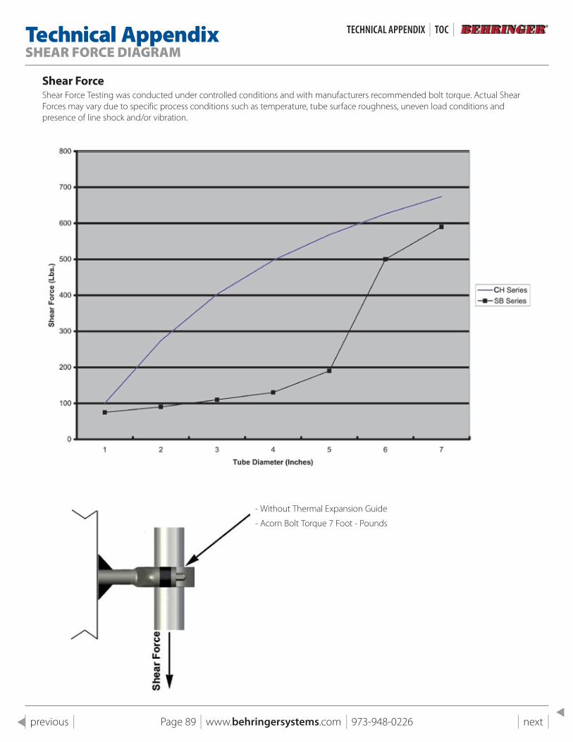
Page 89 | www.behringersystems.com | 973-948-0226 | next | | previous |
Technical AppendixSHEAR FORCE DIAGRAM
shear ForceShear Force Testing was conducted under controlled conditions and with manufacturers recommended bolt torque. Actual Shear Forces may vary due to specific process conditions such as temperature, tube surface roughness, uneven load conditions and presence of line shock and/or vibration.
- Without Thermal Expansion Guide
- Acorn Bolt Torque 7 Foot - Pounds
TeCHNICAL APPeNDIx | TOC |
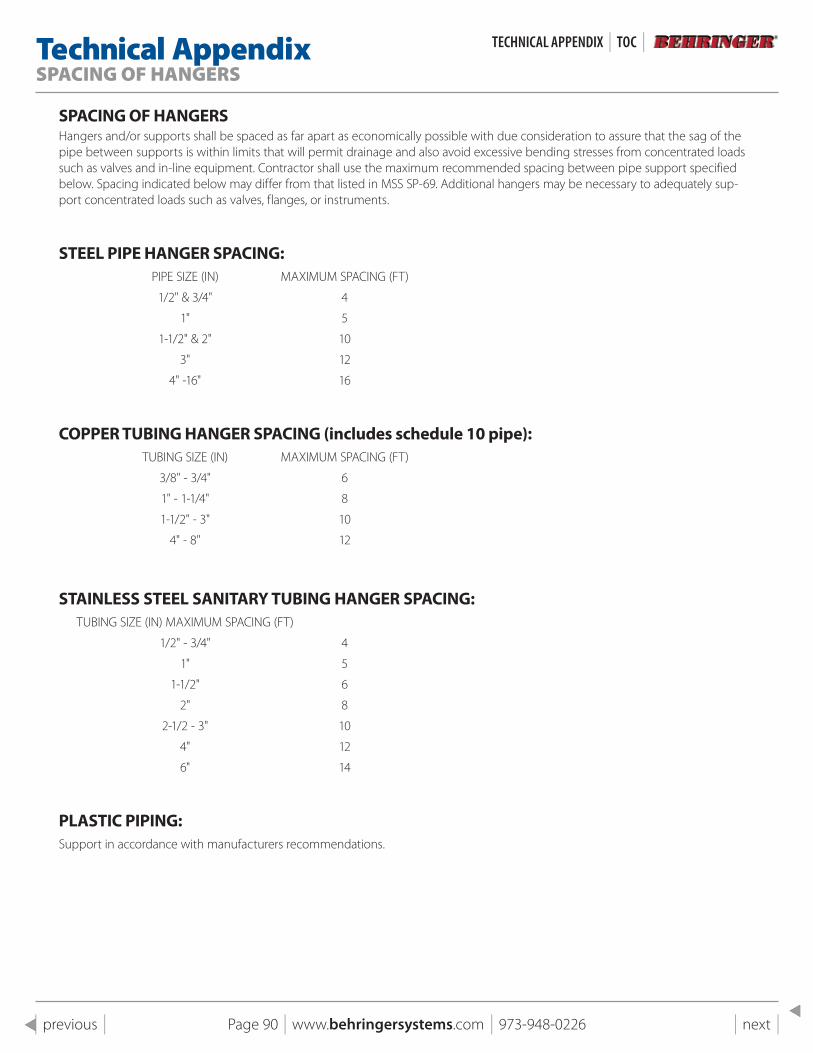
Page 90 | www.behringersystems.com | 973-948-0226 | next | | previous |
Technical AppendixSPACING OF HANGERS
spACING OF HANGERsHangers and/or supports shall be spaced as far apart as economically possible with due consideration to assure that the sag of the pipe between supports is within limits that will permit drainage and also avoid excessive bending stresses from concentrated loads such as valves and in-line equipment. Contractor shall use the maximum recommended spacing between pipe support specified below. Spacing indicated below may differ from that listed in MSS SP-69. Additional hangers may be necessary to adequately sup-port concentrated loads such as valves, flanges, or instruments.
sTEEl pIpE HANGER spACING: PIPE SIZE (IN) MAXIMUM SPACING (FT)
1/2" & 3/4" 4
1" 5
1-1/2" & 2" 10
3" 12
4" -16" 16
COppER TUBING HANGER spACING (includes schedule 10 pipe): TUBING SIZE (IN) MAXIMUM SPACING (FT)
3/8" - 3/4" 6
1" - 1-1/4" 8
1-1/2" - 3" 10
4" - 8" 12
sTAINlEss sTEEl sANITARY TUBING HANGER spACING: TUBING SIZE (IN) MAXIMUM SPACING (FT)
1/2" - 3/4" 4
1" 5
1-1/2" 6
2" 8
2-1/2 - 3" 10
4" 12
6" 14
plAsTIC pIpING:Support in accordance with manufacturers recommendations.
TeCHNICAL APPeNDIx | TOC |

For more information on Behringer Pipe Supports for industrial applications, visit our website:www.behringersystems.com
Or call us at +1 (973) 948-0226
Your local stocking distributor: Behringer Corporation17 Ridge RoadBranchville, NJ 07826Tel: +1 (973) 948-0226Fax: +1 (973) 948-2562email: [email protected]: www.behringersystems.com