hans-dieter harder marc brugger rolf brück · hans-dieter harder marc brugger rolf brück . ......
TRANSCRIPT

1
Future SCR NOX Aftertreatment Systems for Euro 6
Hans-Dieter Harder
Marc Brugger
Rolf Brück

Future SCR NOX Aftertreatment Systems for Euro 6
2
Abstract
Euro 6 legislation will focus on exhaust aftertreatment systems that reduce nitrogen oxide emissions. SCR systems for selective catalytic reduction using a reducing agent (urea/water solution) that is precisely injected and uniformly distributed in the exhaust system have the potential for high conversion rates. This increases the scope for the treatment of nitrogen oxide raw emissions and is likely to have a corresponding positive impact on fuel consumption and CO2 emissions. Overall exhaust aftertreatment can be significantly optimised by raising the exhaust gas temperature before the DOC and before the SCR catalysts.
This paper examines various factors that can affect the efficiency of an SCR system. They include important limiting operating conditions, such as the quality of the evaporation of the urea/water solution (UWS) or the degree of uniform distribution of the ammonia formed by the UWS upstream of the SCR catalyst, as well as criteria that affect the catalysts themselves, including the diesel oxidation catalyst and the SCR catalyst.
This paper also identifies potential resulting from controlled thermal management, e.g. from the use of electrically heated catalysts in a DOC or SCR position. Overall the tests show that the prospects for more efficient Euro 6 NOX exhaust aftertreatment systems are generally good.
Future SCR NOX Aftertreatment Systems for Euro 6
3
1. Introduction
Statutory provisions for exhaust aftertreatment systems for combustion engines demand another dramatic reduction of emissions from car diesel engines, especially with regard to NOX. This can be achieved by improving the operation of catalyst and filter systems. In addition, there are other requirements regarding CO2 and fuel consumption.
These systems are highly complex and cost-intensive. Against this background diesel engines will continue to offer an alternative in future only if the potentials of the overall system are developed and implemented in combination with NOX exhaust aftertreatment.
This paper focuses on the application of a UWS-based system. The future requirements for catalyst systems will change from today’s in many respects:
Utmost priority is given to maximum catalytic conversion because the future potential of combustion engines depends on emissions being reduced to nearly zero, i.e. on the conversion rates of all regulated components being almost 100%.
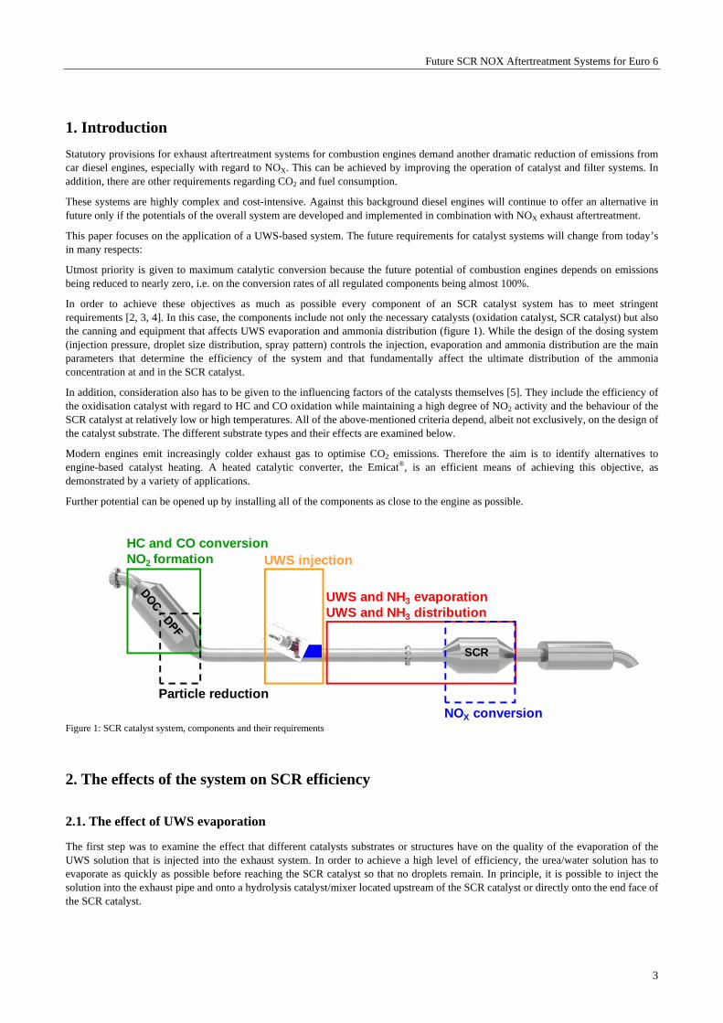
In order to achieve these objectives as much as possible every component of an SCR catalyst system has to meet stringent requirements [2, 3, 4]. In this case, the components include not only the necessary catalysts (oxidation catalyst, SCR catalyst) but also the canning and equipment that affects UWS evaporation and ammonia distribution (figure 1). While the design of the dosing system (injection pressure, droplet size distribution, spray pattern) controls the injection, evaporation and ammonia distribution are the main parameters that determine the efficiency of the system and that fundamentally affect the ultimate distribution of the ammonia concentration at and in the SCR catalyst.
In addition, consideration also has to be given to the influencing factors of the catalysts themselves [5]. They include the efficiency of the oxidisation catalyst with regard to HC and CO oxidation while maintaining a high degree of NO2 activity and the behaviour of the SCR catalyst at relatively low or high temperatures. All of the above-mentioned criteria depend, albeit not exclusively, on the design of the catalyst substrate. The different substrate types and their effects are examined below.
Modern engines emit increasingly colder exhaust gas to optimise CO2 emissions. Therefore the aim is to identify alternatives to engine-based catalyst heating. A heated catalytic converter, the Emicat®, is an efficient means of achieving this objective, as demonstrated by a variety of applications.
Further potential can be opened up by installing all of the components as close to the engine as possible.
Figure 1: SCR catalyst system, components and their requirements
2. The effects of the system on SCR efficiency
2.1. The effect of UWS evaporation
The first step was to examine the effect that different catalysts substrates or structures have on the quality of the evaporation of the UWS solution that is injected into the exhaust system. In order to achieve a high level of efficiency, the urea/water solution has to evaporate as quickly as possible before reaching the SCR catalyst so that no droplets remain. In principle, it is possible to inject the solution into the exhaust pipe and onto a hydrolysis catalyst/mixer located upstream of the SCR catalyst or directly onto the end face of the SCR catalyst.
SCR
HC and CO conversionNO2 formation
Particle reduction
UWS and NH3 evaporationUWS and NH3 distribution
NOX conversion
UWS injection

Future SCR NOX Aftertreatment Systems for Euro 6
4
The aim was to determine the extent to which spraying the solution onto metal catalyst substrates upstream of the SCR catalyst supported the evaporation and especially which of the structures were particularly able to support the evaporation of the droplets. Corresponding tests were carried out on an engine test bench and also examined whether the process was aided by a catalytic coating, and what results could be expected under various limiting conditions (temperature, mass flow and injected volume).
2.1.1 Test setup and boundary conditions
The test was carried out on a 3-litre passenger car diesel engine. The UWS dosing device, the test catalysts and the optical analysis box were integrated in the exhaust system [1]. The more or less droplet-loaded exhaust gas escaping from the test catalyst was fed into a transparent glass box where the flow was analysed with the aid of two flashing stroboscopes. The flashing light was scattered or reflected by droplets in the exhaust gas and recorded by a camera positioned on the other side of the exhaust system. The resulting images were analysed using a method for determining droplet concentration.
2.1.2 Tested catalyst substrates
The aim was to establish the effect of the substrate and the channel structure on evaporation behaviour. In particular, the tests were expected to show the effects of the cell density, the coating and the type/surface of the channel wall (e.g. metal wire fleece vs. smooth walls). In addition, identical substrate structures in seven different lengths ranging from 8 to 150 mm were tested to determine how substrate length affected the quality of evaporation.
The following parameters remained unchanged:
Diameter: 143 mm
Cell density: 200 cpsi (only 40 cpsi for MX)
Foil strength: 65 µm
Coating: 150 g/l hydrolysis coating (40 g/l Al2O3 for PM)
The following substrate parameters varied:
Channel structure: STD, LSPE [5, 6], PM [8], MX
Catalyst length: 8 – 150 mm
Coating: yes / no
Table 1 contains a summary of all the key substrate parameters:
Diameter [mm]
Length [mm] Structure Coating [g/l]
143 mm 8 / 20 / 32 / 55 / 74 / 103 / 150
200 cpsi standard (STD)
uncoated / 150 g/l hydrolysis
143 mm 8 / 20 / 32 / 55 / 74 / 103 / 150
200/400 cpsi LSPE
uncoated / 150 g/l hydrolysis
143 mm 8 / 20 / 32 / 55 / 74 / 103 / 150
200 cpsi PM uncoated / 40 g/l Al2O3
143 mm 8 / 20 / 32 / 55 / 74 / 103 / 150
40 cpsi MX uncoated / 150 g/l hydrolysis
Table 1: Catalyst types used in the analysis of droplet evaporation on the engine test bench

Future SCR NOX Aftertreatment Systems for Euro 6
5
2.1.3 Result
Figure 2 shows the results for droplet frequency downstream of coated Standard and PM substrates of different lengths. The droplet concentration after a length of 8 mm largely corresponds to that before the catalyst. The PM structure can be seen to significantly reduce the concentration after a length of only 20 mm, while droplets are still visible after 32 mm and even 150 mm in the Standard structure. This is primarily due to factors such as optical impermeability (blades in the PM channels) combined with absorbent capillary-active substrate surfaces (wire fleece in the PM-Metalit), which provide a good basis for high evaporation rates.
Figure 2: Comparison of sum images (droplet frequency) downstream of Standard and PM substrates of different lengths (coated, 150 g/l or 40 g/l for PM), load point 300°C / 300 kg/h / 3 ml/min
PM and Standard structures represent the two extremes in this comparison. Shown below are the evaluation figures (droplet area x frequency) of some of the other tested structures plotted against their length. Figure 3 shows this comparison at a load point of 300 kg/h / 300°C / 3 ml/min.
Figure 3: Comparison of evaluation figures (area x frequency) for the downstream droplet concentrations of the tested structures as a function of substrate length (all coated with 150 g/l or 40 g/l for PM, standard also uncoated), 300°C / 300 kg/h, 3 ml/min
As expected, more length increases the likelihood of evaporation in the substrate. A coating also has a clearly positive effect on evaporation. Coated substrates achieve better values irrespective of their structure.
8 mm 20 mm 32 mm 150 mm
Catalyst length
200 cpsiStandard
200 cpsi PM
0
20
40
60
80
100
120
140
160
180
0 20 40 60 80 100 120 140 160
Catalyst length [mm]
Dro
ple
t ar
ea x
fre
qu
ency
[-] PM 200 cpsi
Standard 200 cpsiLSPE 200/400 cpsi MX 40 cpsi

Future SCR NOX Aftertreatment Systems for Euro 6
6
Nonetheless, the structure of the substrate has a clearly detectable effect. The best result by far was produced by a PM structure, which contained hardly any droplets after as little as 20 mm. In the 40 cpsi MX structure and LSPE 200/400 cpsi no droplets were detected after a substrate length of 70 and 100 mm respectively (each with a coating). In all other structures there was detectable slip even after a substrate length of 150 mm. The more pronounced the optical obstruction of the channel and the liquid storage capacity of the channel wall are the more effectively the liquid can be evaporated.
2.2 The effect of ammonia distribution
It is safe to assume that the injection of a UWS into the exhaust pipe, even when supported by measures to aid UWS evaporation, such as a PM-Metalit or a mixer, does not result in a perfectly uniform ammonia distribution across the inlet cross-section of the downstream SCR catalyst.
Uniformity of distribution can only be accomplished through greater substrate lengths and by deflecting the flow. However, this is generally unachievable for reasons of space and backpressure.
It would therefore be beneficial if the SCR catalyst itself were able to attain a certain level of uniformity in the ammonia concentration along its length. The next section of this paper examines the ability of various substrate structures to facilitate radial mixing along the length of the catalyst.
2.2.1 Test setup and boundary conditions
Engine, exhaust system and canning geometry, including the design of the dosing point, were identical to the setup described above [1]. However, instead of a UWS injector, an axially displaceable gas lance was used to inject gaseous ammonia. This made it possible to adjust the mixing section or the quality of the ammonia distribution in front of the SCR catalyst. A preset amount of sample gas was injected via a mass flow controller fitted with a nozzle that had four 0.5 mm openings. The nozzle was positioned directly in front of the substrate end face in order to achieve as inhomogeneous an NH3 distribution in the substrate inlet as possible. In this respect, the test setup represented a worst-case scenario.
As in the previous test, it was possible to swap over the test catalysts. A gas sensor, which could be moved along two axes parallel to the plane of the catalyst outlet, was positioned directly downstream of the catalyst. This traversing unit was able to trace the required measurement grid automatically. The ammonia concentration was measured with an FTIR analyser.
2.2.2 Tested catalyst substrates
The catalysts used in the test were a subset of the test substrates described in table 1. Only uncoated substrates were used to exclude the effects of adsorbed ammonia. The catalysts are listed in table 2.
Diameter [mm]
Length [mm] Structure Coating [g/l]
143 mm 74.5 and 150 mm 200 cpsi Standard
uncoated
143 mm 74.5 and 150 mm 200/400 cpsi LSPE
uncoated
Table 2: Catalyst types used in the analysis of radial ammonia distribution on the engine test bench
2.2.3 The effect of substrate structures on the uniformity index
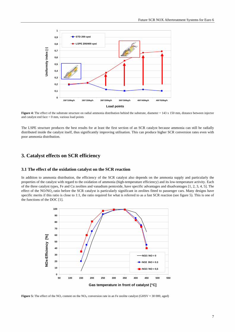
Figure 4 shows the uniformity index of two different structures (standard and LSPE) with a substrate length of 150 mm each.
The perforated flat layers of the LSPE structure permit the gas to flow perpendicular to the foil pack. At load points with low flow speeds the effect is initially small, above 150 kg/h the benefits of the LSPE structure steadily increase in terms of dramatically improved uniform ammonia distribution behind the catalyst, compared to the standard structure.
Future SCR NOX Aftertreatment Systems for Euro 6
7
Figure 4: The effect of the substrate structure on radial ammonia distribution behind the substrate, diameter = 143 x 150 mm, distance between injector and catalyst end face = 0 mm, various load points
The LSPE structure produces the best results for at least the first section of an SCR catalyst because ammonia can still be radially distributed inside the catalyst itself, thus significantly improving utilisation. This can produce higher SCR conversion rates even with poor ammonia distribution.
3. Catalyst effects on SCR efficiency
3.1 The effect of the oxidation catalyst on the SCR reaction
In addition to ammonia distribution, the efficiency of the SCR catalyst also depends on the ammonia supply and particularly the properties of the catalyst with regard to the oxidation of ammonia (high-temperature efficiency) and its low-temperature activity. Each of the three catalyst types, Fe and Cu zeolites and vanadium pentoxide, have specific advantages and disadvantages [1, 2, 3, 4, 5]. The effect of the NO/NO2 ratio before the SCR catalyst is particularly significant in zeolites fitted to passenger cars. Many designs have specific merits if this ratio is close to 1:1, the ratio required for what is referred to as a fast SCR reaction (see figure 5). This is one of the functions of the DOC [1].
Figure 5: The effect of the NO2 content on the NOX conversion rate in an Fe zeolite catalyst (GHSV = 30 000, aged)
0
0,1
0,2
0,3
0,4
0,5
0,6
0,7
0,8
0,9
1
150°/100kg/h 150°/150kg/h 300°/200kg/h 300°/300kg/h 400°/400kg/h 400°/520kg/h
Load points
Un
ifo
rmit
y i
nd
ex
[-]
STD 200 cpsi
LSPE 200/400 cpsi
0
10
20
30
40
50
60
70
80
90
100
50 100 150 200 250 300 350 400 450 500 550
Gas temperature in front of catalyst [°C]
NO
x-E
ffic
ien
cy
[%]
NO2 / NO = 0
NO2 /NO = 0.3
NO2 / NO = 0,5
Future SCR NOX Aftertreatment Systems for Euro 6
8
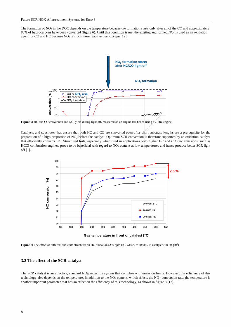
The formation of NO2 in the DOC depends on the temperature because the formation starts only after all of the CO and approximately 80% of hydrocarbons have been converted (figure 6). Until this condition is met the existing and formed NO2 is used as an oxidation agent for CO and HC because NO2 is much more reactive than oxygen [12].
Figure 6: HC and CO conversion and NO2 yield during light off, measured on an engine test bench using a 2-litre engine
Catalysts and substrates that ensure that both HC and CO are converted even after short substrate lengths are a prerequisite for the preparation of a high proportion of NO2 before the catalyst. Optimum SCR conversion is therefore supported by an oxidation catalyst that efficiently converts HC. Structured foils, especially when used in applications with higher HC and CO raw emissions, such as HCCI combustion engines, prove to be beneficial with regard to NO2 content at low temperatures and hence produce better SCR light off [1].
Figure 7: The effect of different substrate structures on HC oxidation (250 ppm HC, GHSV = 30,000, Pt catalyst with 50 g/ft2)
3.2 The effect of the SCR catalyst
The SCR catalyst is an effective, standard NOX reduction system that complies with emission limits. However, the efficiency of this technology also depends on the temperature. In addition to the NO2 content, which affects the NOX conversion rate, the temperature is another important parameter that has an effect on the efficiency of this technology, as shown in figure 8 [12].
co
nve
rsio
n [
% ]
40
60
80
100 CO conversion HC conversion NO2 formation
NO2 formation starts after HC/CO-light off
NO2 formation
NO2 use
90
91
92
93
94
95
96
97
98
99
100
50 100 150 200 250 300 350 400 450 500 550
Gas temperature in front of catalyst [°C]
HC
co
nve
rsio
n [
%]
200 cpsi STD
200/400 LS
200 cpsi PE
2,5 %

Future SCR NOX Aftertreatment Systems for Euro 6
9
Figure 8: NOX conversion of a standard Fe-based SCR catalyst as a function of exhaust gas temperatures, measured in a model gas reactor under synthetic test conditions (NOX feed: 100% NO)
Other influencing parameters that have a bearing on the effectiveness of an SCR catalyst include the cell density of the substrate structure; structured foils produce better results here, too [1]. These become apparent, for example in cases where an LSPE structure is used to ensure the highly uniform distribution of gaseous ammonia over the cross-section of the SCR catalyst. This substantially improves the utilisation of the substrate and makes it possible to increase the SCR conversion rate even with poor ammonia distribution (see figure 4).
Figure 9: The effect of substrate structures on storage speed (NH3 inlet concentration = 500 ppm, temperature = 200° C, RG = 30000 1/h)
LS blades improve the mass transfer from the gas to the channel wall. This accelerates the absorption of the injected/formed NH3, leading to a more rapid rise in NOX conversion (figure 9). Improved mass transfer also substantially increases effectiveness at higher temperatures.
NO
X c
onve
rsio
n [%
]
0
2 0
4 0
6 0
8 0
1 0 0
Temperature [°C]1 50 2 0 0 2 50 300 350 400 450 5 0 0

Future SCR NOX Aftertreatment Systems for Euro 6
10
4. Temperature management of SCR systems
In addition to the mere activity of the SCR catalyst, temperature is a major factor in the dosing of the reducing agent (UWS). The conversion of urea to ammonia and the prevention of deposits in the exhaust system demand that the start temperature does not drop to below a value between 150°C and 200°C, depending on the application. Higher exhaust gas temperatures are preferable in terms of exhaust aftertreatment. A CO2-minimised supply of this energy is essential to maintain a positive total energy balance.
There are different methods of raising the temperature in the exhaust system. Engine-based measures (late post-injection, charge air throttling, etc.) are effective but the fact that the entire downstream exhaust system is heated cannot be ignored. An integrated system, consisting of a DOC, DPF and an SCR catalyst in the underbody, requires a lot of energy to raise the temperature in the SCR catalyst sufficiently. There may be alternatives that are able to increase the temperature directly, i.e. locally. One example is the electrically heated catalyst [9].
4.1 The electrically heated catalyst Emicat®
4.1.1 Design, function, potential applications
The aim of the development of electrically heated catalysts was the fast light off of catalytic activity even under unfavourable cold start conditions, i.e. at very low exhaust gas temperatures. Since the crucial factor for this activity is the temperature of the substrate rather than that of the exhaust gas the design focused on ensuring that as much as possible of the available electric power was used to heat the metal matrix, in part directly and in part by highly efficient heat transfer from the exhaust gas.
To this end, the actual heater was designed as an integral part of the catalyst in the form of a honeycomb disc in the catalyst inlet. This directly heated disc also has a catalytic coating, which allows it to start converting pollutants immediately. The disc is mechanically supported by the second part of the catalyst, the support catalyst. This catalyst and other downstream components are heated by the exhaust gas, which has been heated by the disc.
The disc works on the principle of a heating coil. Power is supplied at one end by an electrical connection, which conducts electricity to the foil packet via a half shell. The resistance of the foil packet itself determines the electric power of the heated catalyst. Like the normal winding process of the metal matrix, the disc receives its specific form by being wound into an S shape. Contact with the vehicle mass is provided by a second half shell, which is usually connected to another section of the catalyst jacket or via a separate contact (figure 10).
An air gap prevents short circuits inside the heated disc and ensures that power flows through every part of it. The heated disc is mechanically supported by insulated pins that are soldered to the heated disc and the support catalyst. This construction ensures that the catalyst is able to permanently withstand the high thermal and mechanical loads in the exhaust system. [6].
Figure 10: Design of the electrically heated catalyst Emicat®
Electrical connection
Electrical heated matrix
Inner mantel
Outer mantel
Half shell
Support pin
MatrixSupport pin
Future SCR NOX Aftertreatment Systems for Euro 6
11
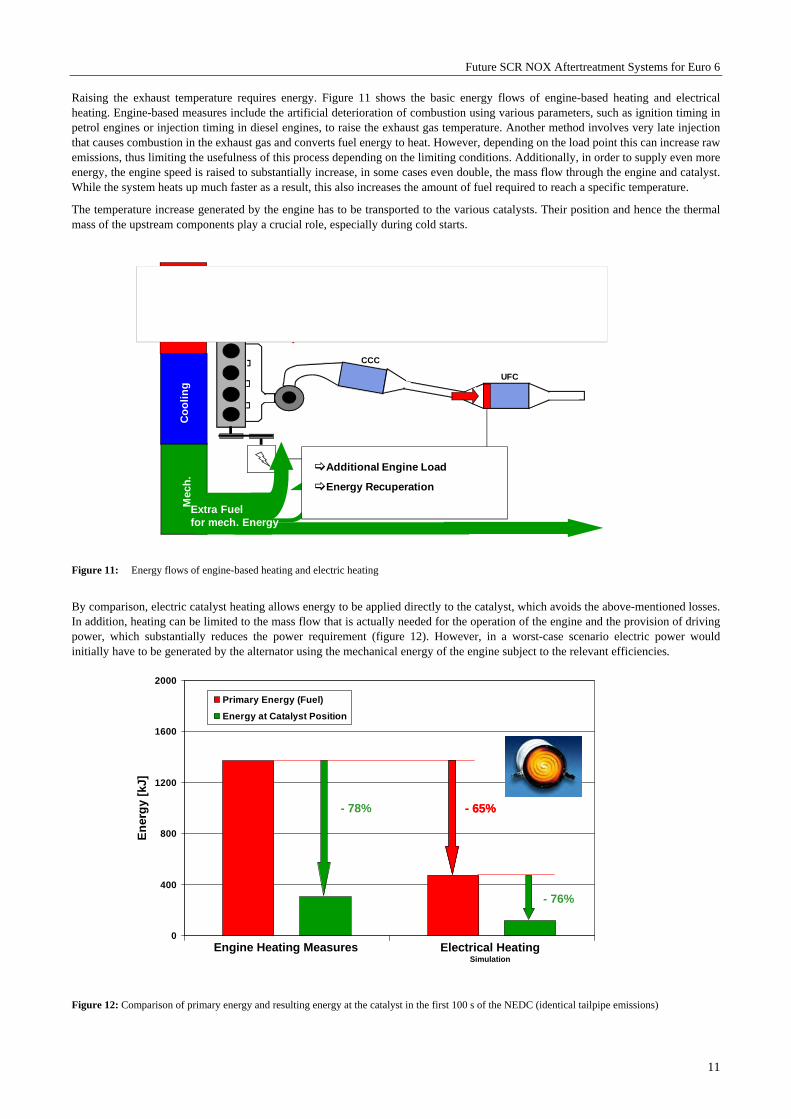
Raising the exhaust temperature requires energy. Figure 11 shows the basic energy flows of engine-based heating and electrical heating. Engine-based measures include the artificial deterioration of combustion using various parameters, such as ignition timing in petrol engines or injection timing in diesel engines, to raise the exhaust gas temperature. Another method involves very late injection that causes combustion in the exhaust gas and converts fuel energy to heat. However, depending on the load point this can increase raw emissions, thus limiting the usefulness of this process depending on the limiting conditions. Additionally, in order to supply even more energy, the engine speed is raised to substantially increase, in some cases even double, the mass flow through the engine and catalyst. While the system heats up much faster as a result, this also increases the amount of fuel required to reach a specific temperature.
The temperature increase generated by the engine has to be transported to the various catalysts. Their position and hence the thermal mass of the upstream components play a crucial role, especially during cold starts.
Figure 11: Energy flows of engine-based heating and electric heating
By comparison, electric catalyst heating allows energy to be applied directly to the catalyst, which avoids the above-mentioned losses. In addition, heating can be limited to the mass flow that is actually needed for the operation of the engine and the provision of driving power, which substantially reduces the power requirement (figure 12). However, in a worst-case scenario electric power would initially have to be generated by the alternator using the mechanical energy of the engine subject to the relevant efficiencies.
Figure 12: Comparison of primary energy and resulting energy at the catalyst in the first 100 s of the NEDC (identical tailpipe emissions)
UFC
CCC
Mec
h.
Co
oli
ng
Exh
aust
Extra Fuelfor mech. Energy
Extra Fuelfor Heating
Additional Engine Load
Energy Recuperation
0
400
800
1200
1600
2000
En
erg
y [k
J]
Primary Energy (Fuel)
Energy at Catalyst Position
- 78%
- 76%
- 65%- 65%
Engine Heating Measures Electrical HeatingSimulation
Future SCR NOX Aftertreatment Systems for Euro 6
12
Engine-based heating consumes almost three times as much energy as electric heating to reach a defined catalyst temperature. Ultimately, electric heating requires two to three times less primary energy to achieve a similar level of efficiency (figure 12).
In terms of power consumption this makes the Emicat® a sensible solution for modern vehicle architectures.
4.2 The Emicat® in SCR exhaust aftertreatment systems
4.2.1 DOC Position
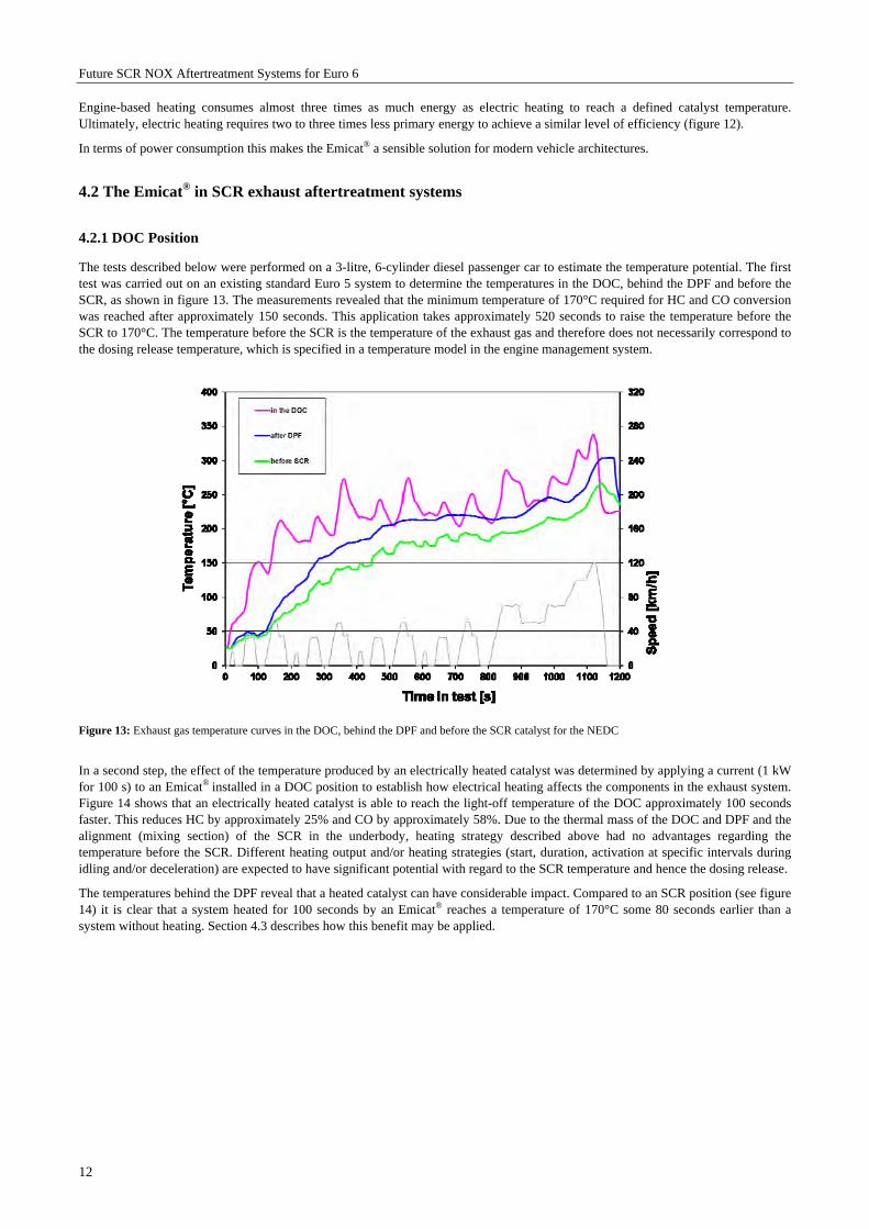
The tests described below were performed on a 3-litre, 6-cylinder diesel passenger car to estimate the temperature potential. The first test was carried out on an existing standard Euro 5 system to determine the temperatures in the DOC, behind the DPF and before the SCR, as shown in figure 13. The measurements revealed that the minimum temperature of 170°C required for HC and CO conversion was reached after approximately 150 seconds. This application takes approximately 520 seconds to raise the temperature before the SCR to 170°C. The temperature before the SCR is the temperature of the exhaust gas and therefore does not necessarily correspond to the dosing release temperature, which is specified in a temperature model in the engine management system.
Figure 13: Exhaust gas temperature curves in the DOC, behind the DPF and before the SCR catalyst for the NEDC
In a second step, the effect of the temperature produced by an electrically heated catalyst was determined by applying a current (1 kW for 100 s) to an Emicat® installed in a DOC position to establish how electrical heating affects the components in the exhaust system. Figure 14 shows that an electrically heated catalyst is able to reach the light-off temperature of the DOC approximately 100 seconds faster. This reduces HC by approximately 25% and CO by approximately 58%. Due to the thermal mass of the DOC and DPF and the alignment (mixing section) of the SCR in the underbody, heating strategy described above had no advantages regarding the temperature before the SCR. Different heating output and/or heating strategies (start, duration, activation at specific intervals during idling and/or deceleration) are expected to have significant potential with regard to the SCR temperature and hence the dosing release.
The temperatures behind the DPF reveal that a heated catalyst can have considerable impact. Compared to an SCR position (see figure 14) it is clear that a system heated for 100 seconds by an Emicat® reaches a temperature of 170°C some 80 seconds earlier than a system without heating. Section 4.3 describes how this benefit may be applied.
Future SCR NOX Aftertreatment Systems for Euro 6
13
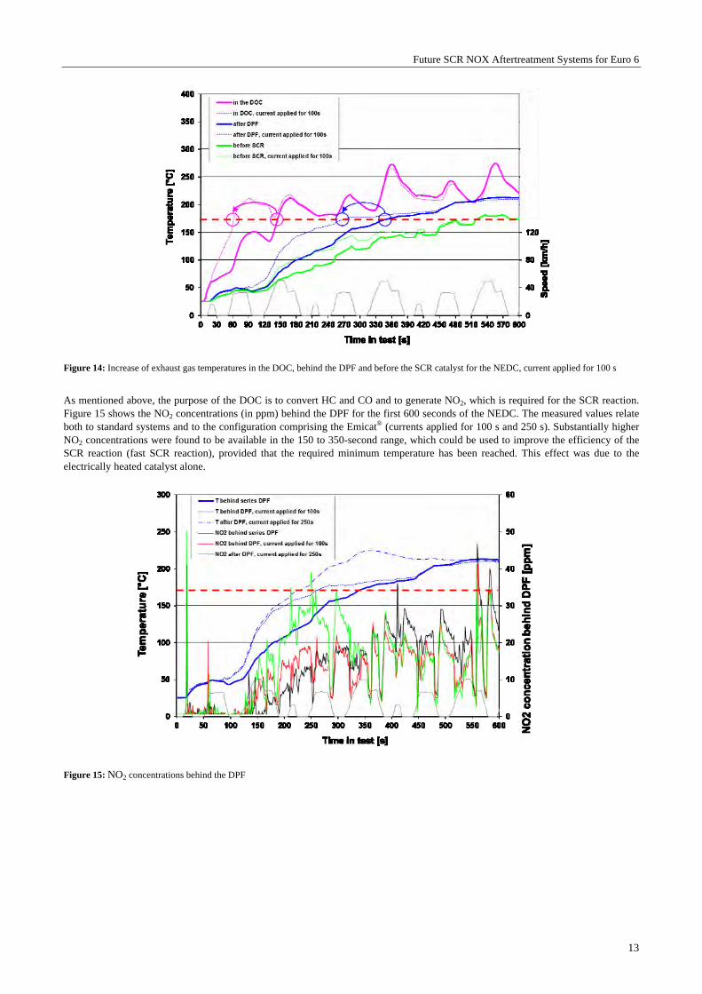
Figure 14: Increase of exhaust gas temperatures in the DOC, behind the DPF and before the SCR catalyst for the NEDC, current applied for 100 s
As mentioned above, the purpose of the DOC is to convert HC and CO and to generate NO2, which is required for the SCR reaction. Figure 15 shows the NO2 concentrations (in ppm) behind the DPF for the first 600 seconds of the NEDC. The measured values relate both to standard systems and to the configuration comprising the Emicat® (currents applied for 100 s and 250 s). Substantially higher NO2 concentrations were found to be available in the 150 to 350-second range, which could be used to improve the efficiency of the SCR reaction (fast SCR reaction), provided that the required minimum temperature has been reached. This effect was due to the electrically heated catalyst alone.
Figure 15: NO2 concentrations behind the DPF

Future SCR NOX Aftertreatment Systems for Euro 6
14
4.2.2 SCR Position
Following the highly positive results produced by the Emicat® in a DOC position this section examines the effects of an SCR position. Initially, special attention was given to improving the SCR reaction by positioning the Emicat® directly in front of the SCR catalyst. Since SCR substrates are usually fitted in the underbody downstream of the DOC and DPF, the disadvantages of having to heat the exhaust system and its components become particularly evident. Electrical heating of the SCR catalyst or an upstream hydrolysis catalyst would perform much better here.
Generally, this is a particular problem at low loads, such as urban cycles. Figure 16 shows the exhaust gas temperatures of a van with an SCR system in the Artemis Urban Cycle. In this example an electrically heated hydrolysis catalyst was fitted upstream of the SCR catalyst. Normally, the temperature before the heated catalyst would correspond to the SCR inlet temperature. The selected heating strategy was to provide heating until the exhaust gas temperature rose to 180°C, thus keeping the temperature in the SCR substrate at a relatively constant level. Even under these limiting conditions it was thus possible to achieve very good NOX conversion rates. This is another area where a start/stop function could open up additional potential.
Figure 16: Temperatures and NOX emissions using a heated SCR system in the Artemis Urban Cycle
The SCR catalyst patently achieves significant NOX conversion rates even at temperatures below 180°C as long as sufficient ammonia is stored in the coating. The supply of ammonia or the injection of UWS requires a minimum temperature (between 160 and 180°C) to ensure evaporation, preparation and hydrolysis.
4.3 Potential optimised arrangement of system components
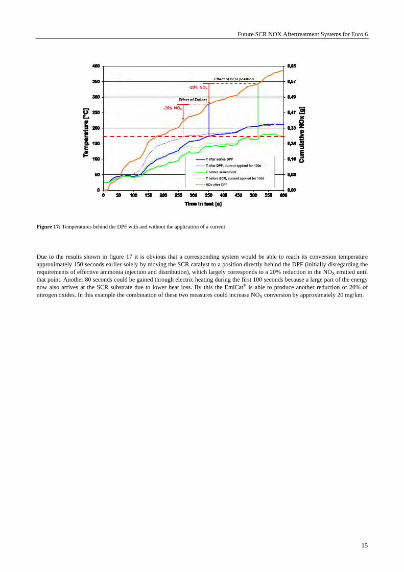
This paper focuses on the optimisation of existing Euro 6 NOX exhaust aftertreatment systems with an SCR catalyst that has to be installed in the underbody for a number of reasons (volume, installation space, length of the mixing section). The temperature curves and the cumulative NOX raw emissions shown in figure 17 formed the basis for an estimate of the potential that could be developed by an SCR catalyst installed closer to the engine combined with additional electric heating in a DOC position, where appropriate.
Future SCR NOX Aftertreatment Systems for Euro 6
15
Figure 17: Temperatures behind the DPF with and without the application of a current
Due to the results shown in figure 17 it is obvious that a corresponding system would be able to reach its conversion temperature approximately 150 seconds earlier solely by moving the SCR catalyst to a position directly behind the DPF (initially disregarding the requirements of effective ammonia injection and distribution), which largely corresponds to a 20% reduction in the NOX emitted until that point. Another 80 seconds could be gained through electric heating during the first 100 seconds because a large part of the energy now also arrives at the SCR substrate due to lower heat loss. By this the EmiCat® is able to produce another reduction of 20% of nitrogen oxides. In this example the combination of these two measures could increase NOX conversion by approximately 20 mg/km.

Future SCR NOX Aftertreatment Systems for Euro 6
16
Summary / outlook
This paper dealt with various factors that affect the efficiency of an SCR system, such as the quality of the evaporation of the urea/water solution (UWS) or the uniformity of the distribution of the ammonia formed by the UWS at a point upstream of the SCR catalyst, as well as criteria that relate to the catalysts themselves, including the diesel oxidation catalyst and the SCR catalyst. Both these factors were the subject of comprehensive tests that were carried out on a variety of metal catalyst substrates. Radially open catalyst structures proved to have major advantages over standard substrates with smooth channels when it comes to the preparation of the UWS, the supply of ammonia to the SCR catalyst and the conversion of nitrogen oxides and hydrocarbons. These structures are able to increase the efficiency of a diesel catalytic converter system. In terms of UWS evaporation the PM-Metalit was shown to be particularly effective at supporting the evaporation and hydrolysis of the UWS when installed in an SCR system downstream of the injection point. Wherever a high level of uniform distribution of gaseous ammonia over the cross-section of the SCR catalyst is required, the LSPE structure offers considerable advantages thanks to its perforated foils, which significantly improve substrate utilisation, thus achieving higher SCR rates even with poor ammonia distribution. Tests carried out on the oxidation catalyst revealed that hydrocarbons, in particular, seemed to be able to displace NO from the surface of the catalyst or reduce already formed NO2 back to NO, which means that strong HC activity of the oxidation catalyst is a prerequisite for the production of a high NO2 content before the SCR catalyst. Above 250°C LS and PE structures are particularly effective at converting HC even at low or medium channel and space velocities. On the basis of these detailed results an correspondingly optimised SCR catalytic converter system should comprise the following components:
Oxidation catalyst based on an LS or PE structure First SCR catalyst substrate based on an LSPE structure Second SCR catalyst substrate based on an LS structure
An electrically heated catalyst, the Emicat®, in combination with the remaining necessary components arranged in the interest of best possible thermal management, offers further potential for improvement. Optimum integration of the different functionalities and operating parameters enables the electrically heated catalyst to provide effective thermal management also in terms of energy. Compared to conventional engine-based heating there are a number of further advantages, such as locally targeted energy input, short controlled systems with fast response times and good controllability and, ultimately, little dependence on specific engine operating points. To some extent this opens the path for the development of new heating and control strategies, especially relating to the operation of SCR systems.
The Emicat® provides a previously unavailable degree of freedom with regard to earlier light off, the formation of NO2 and offers more scope for NOX raw emissions and reductions in fuel consumption, all of which should be analysed and developed. The design of the mixing section for the urea/water solution, which has to meet the requirements of ammonia evaporation and distribution to optimise the efficiency of the SCR reaction, is going to be a particular challenge.

Future SCR NOX Aftertreatment Systems for Euro 6
17
Bibliography [1] P. Hirth, R. Brück, H. Stock: Emitec GmbH; FAD Dresden 2010: „ Metallische SCR-Katalysatorsysteme; Kenngrößen für
optimale Effektivität “ [2] O. Kröcher: Paul Scherrer Institut; Haus der Technik, MinNOx, 2007; „New Challenges for Urea-SCR Systems: From Vanadia-
Based to Zeolite-Based SCR Catalysts“ [3] S. Malmberg, M. Votsmeier, J. Gieshoff, N. Söger, L. Mußmann: Umicore AG; A. Schuler, A. Drochner: TU Darmstadt; CTI-
Abgastechnik, Januar 2007; „Untersuchung und Simulation der NH3-SCR Reaktion an FE-Zeolithen; Experimental Investigation and Simulation of NH3-SCR Reaction on FE-Exchanged Zeolites”
[4] I. Nova: Politecnico di Milano; Haus der Technik, MinNOx, 2007; „Mechanism and Modelling of the NO/NO2/NH3-SCR
Reactions for Aftertreatment of Diesel Exhausts” [5] P. Spurk, M. Pfeifer, F.-W. Schütze: Umicore AG & Co. KG; CTI-Abgastechnik, Januar 2007; „Anforderungen an den DOC &
DPF in Dieselabgasnachbehandlungssystemen mit NOx Nachbehandlung“ [6] W. Maus, R. Brück: Emitec GmbH; 26. Internationales Wiener Motorensymposium, 2005; „Die Zukunft der heterogenen Katalyse
im Automobil: Turbulente Katalysatoren für Otto- und Diesel-Anwendungen“ [7] U. Pfahl, M. Rice, J. Kramer, C. Bruestle: Emitec, Inc.; SAE 2009-01-1073; „Advanced Catalyst Substrate Technology
Development for Cost Efficient Exhaust Gas Aftertreatment Systems” [8] W: Maus, R. Brück, P. Hirth: Emitec GmbH; 10. Internationales Stuttgarter Symposium 2010; „SCR- und Partikel-
Abgasnachbehandlungssysteme für Heavy Duty EU VI und NRMM Stufe VI“ [9] F. J. Hanel, Alpina GmbH & Co., E. Otto, BMW AG, R. Brück, Emitec GmbH ‘Electrically Heated Catalytic Converter (EHC) in
the BMW Alpina B12 5.7 Switch-Tronic’ 1996 SAE International Congress and Exposition Detroit, Michigan (USA), 1996
[10] F. J. Hanel, Alpina GmbH & Co., E. Otto, BMW AG, R. Brück, T. Nagel. N. Bergau, Emitec GmbH ‘Practical Experience with the EHC System in the BMW Alpina B12’; 1997 SAE International Congress and Exposition Detroit, Michigan (USA), 1997
[11] A. Wiartalla, C. Severin, Y. Rosefort, H. Kemper, FEV Motorentechnik GmbH; H. Kwee, Lehrstuhl für Verbrennungskraftmaschinen, RWTH Aachen ‘Diesel Hybrid and Exhaust Aftertreatment – Synergies and Optimization Potentials’ MinNox Berlin, Juni 2008
[12] A. Waldhelm , Prof. Dr. C. Beidl: TU Darmstadt vkm; Dr. P. Spurk , H.-D. Noack: Umicore AG & Co. KG; R. Brück, R. Konieczny , M. Brugger: Emitec GmbH; Dresden Emission Control Juni 2010: “Aktives Temperaturmanagement in SCR-Systemen - Anwendungsmöglichkeiten und Betriebsstrategien des elektrisch beheizbaren Katalysators EmiCat®”