hard/soft informatio n fusion in the condition …
TRANSCRIPT

The Pennsylvania State University
The Graduate School
College of Information Sciences and Technology
HARD/SOFT INFORMATION FUSION
IN THE CONDITION MONITORING OF AIRCRAFT
A Dissertation in
Information Sciences and Technology
by
Joseph T. Bernardo
2014 Joseph T. Bernardo
The U.S. Government has a copyright license in this work pursuant to a Cooperative Research and Development Agreement with Naval Air Warfare Center Aircraft Division Patuxent River.
Submitted in Partial Fulfillment of the Requirements
for the Degree of
Doctor of Philosophy
December 2014

The dissertation of Joseph T. Bernardo was reviewed and approved* by the following:
David L. Hall Professor, College of Information Sciences and Technology Dissertation Advisor Chair of Committee Michael D. McNeese Co-director, General Electric (GE) Center for Collaborative Research in
Intelligent Gas Systems (CCRNGS) Research Center, Professor, College of Information Sciences and Technology, Affiliate Professor of Psychology, Affiliate Professor of Learning and Performance Systems Guoray Cai Associate Professor of Information Sciences and Technology, Affiliate Associate Professor of Geography Richard L. Tutwiler Deputy Director, Center for Network-Centric Cognition and Information
Fusion (NC2IF), Professor of Acoustics, Affiliate Professor of Information Sciences and Technology Carleen Maitland Director of Graduate Programs, Interim Associate Dean for Undergraduate and Graduate Studies, Associate Professor of Information Sciences and Technology, Affiliate Professor of the School of International Affairs
*Signatures are on file in the Graduate School
iii
ABSTRACT
The synergistic integration of information from electronic sensors and human
sources is called hard/soft information fusion. In the condition monitoring of aircraft, the
addition of the multisensory capability of human cognition to traditional condition
monitoring may create a more complete picture of aircraft condition. A large data set from
Naval Air Systems Command (NAVAIR) on maintenance of multi-mission vertical takeoff
and landing (VTOL) 22 series B (MV-22B) aircraft provided the opportunity to explore the
value of hard/soft information fusion in aviation maintenance.
First, cognitive and functional frameworks were applied to hard/soft information
fusion in the condition monitoring of aircraft. The steps of the Orasanu decision process
model were applied to the macrocognitive functions and processes of the aviation
maintainer. Emerging literature on hard/soft information fusion in condition monitoring was
organized into the levels of the Joint Directors of Laboratories (JDL) data fusion process
model, and the levels were applied to the process functions of aviation maintenance.
Second, a research design was created for a retrospective analysis of sensor
readings, human observations, and choices made in the maintenance of MV-22B aircraft.
The data set from Decision Knowledge Programming for Logistics Analysis and Technical
Evaluation (DECKPLATE), a NAVAIR database, provided information collected without
the interference of interviewer bias.
Third, a research methodology was created for studying hard/soft information fusion
in aviation maintenance. Content analysis of the descriptive and corrective action narratives
showed faults and aircraft components chosen for repair, replacement, fabrication, or
calibration. Problem complexity was found to be an important factor. Additionally, expertise
level also had an effect, and it was described through longitudinal trending.

iv
Fourth, the addition of human observation to sensor data was highly associated with
the aircraft components chosen for action. Additionally, for complex problems, the addition
of human observation to sensor data was significantly associated with improved outcomes.
Descriptive statistics showed reduced diagnostic effort with human observation in complex
problems. The improved outcomes and reduced diagnostic effort with human observation in
complex problems may reduce operational maintenance cost, increase mission readiness,
and increase flight safety.
Keywords: hard/soft information fusion, condition-based maintenance, condition
monitoring, aircraft maintenance, human factors, and decision-making

v
TABLE OF CONTENTS
Contents
LIST OF FIGURES ................................................................................................................. viii
LIST OF TABLES ................................................................................................................... x
LIST OF EQUATIONS ........................................................................................................... xi
ACKNOWLEDGEMENTS ..................................................................................................... xii
Chapter 1 Introduction ............................................................................................................ 1
Definitions ........................................................................................................................ 1 Sociotechnical Systems .................................................................................................... 2 Failure Modes and Effects Analysis (FMEA) and Failure Modes, Effects, and Criticality Analysis (FMECA) ....................................................................................... 5
FMEA and the JDL Model ............................................................................................... 8 Motivation ........................................................................................................................ 9 Research Questions .......................................................................................................... 10 Findings and Implications ................................................................................................ 11 Research Goal and Contributions ..................................................................................... 12 Roadmap for this Dissertation .......................................................................................... 13
Chapter 2 Background: The Context of Maintenance Work on MV-22B Aircraft ................ 16
Introduction to Naval Aviation ........................................................................................ 16 MV-22B Bell Boeing Osprey .......................................................................................... 19 How Aircraft Work .......................................................................................................... 24 Flight Crew ...................................................................................................................... 32 Pilots ................................................................................................................................ 33 Warrant Officers .............................................................................................................. 34 Maintainers....................................................................................................................... 35 Aviation Maintenance ...................................................................................................... 36
Chapter 3 Literature Review ................................................................................................... 40
Macrocognition ................................................................................................................ 40 Machines Need People to ... but People Need Machines to ... ......................................... 42 Condition-Based Maintenance Plus ................................................................................. 44 Hard/Soft Information Fusion .......................................................................................... 47 JDL Data Fusion Process Model ...................................................................................... 49
The JDL Model and CBM+ ...................................................................................... 50 Organizing the Literature on Hard/Soft Fusion in Condition Monitoring into Levels of the JDL Data Fusion Process Model .............................................................. 53
Level 2/3 Human-Influenced Diagnostics and Prognostics ..................................... 53

vi
Level 2/3/5 Integrated Machine- and Human-Based Diagnostics and Prognostics ........................................................................................................... 54
Level 5 Human Information Processing ................................................................... 55 Alternative Information Fusion Frameworks ................................................................... 56 Summary .......................................................................................................................... 58
Chapter 4 Cognitive and Functional Frameworks .................................................................. 61
Cognitive Framework for Hard/Soft Information Fusion in the Condition Monitoring of Aircraft.................................................................................................... 61
Functional Framework for Hard/Soft Information Fusion in the Condition Monitoring of Aircraft.................................................................................................... 64
Chapter 5 Research Design ..................................................................................................... 68
Philosophy ........................................................................................................................ 68 Operating Environment .................................................................................................... 69 Population ........................................................................................................................ 71 Data Set Development and Measures .............................................................................. 72 Summary .......................................................................................................................... 74
Chapter 6 Methodology .......................................................................................................... 75
Design and Tests .............................................................................................................. 76 Limitations and Operational Definitions .......................................................................... 76 Explanatory Variables ...................................................................................................... 77 Response Variables .......................................................................................................... 79 Development of Hypotheses ............................................................................................ 80 Summary .......................................................................................................................... 81
Chapter 7 Summary of Results ............................................................................................... 82
Hypothesis 1 ..................................................................................................................... 82 Descriptive Statistics ................................................................................................ 82 Test and Conditions .................................................................................................. 90 Test of Significance .................................................................................................. 92
Hypotheses 2 and 3 .......................................................................................................... 93 Descriptive Statistics ................................................................................................ 93 Test Conditions for H2 ............................................................................................. 96 Test of Significance for H2 ...................................................................................... 97 Test Conditions for H3 ............................................................................................. 98 Test of Significance for H3 ...................................................................................... 98
Chapter 8 Discussion .............................................................................................................. 100
Suggestions for Further Research .................................................................................... 105
Chapter 9 Conclusions ............................................................................................................ 107
References ................................................................................................................................ 110

vii
Appendix A .............................................................................................................................. 124
List of 1-, 2-, and 3-Grams Containing Adjectives, References to Periods, or References to Persons, Used to Identify Human Observation in the Descriptive Narrative and Corrective Action Narratives of Diagnostic Maintenance Actions Records ........................................................................................ 124
Appendix B .............................................................................................................................. 131
Type MAF Codes and Descriptions ................................................................................. 131
Appendix C .............................................................................................................................. 133
Nonstandard Words Found in Descriptive and Corrective Action Narratives ................. 133
viii
LIST OF FIGURES
Figure 1 – FMEA analysis cycle .............................................................................................. 7
Figure 2 – Associations between sources of information, aircraft components chosen for repair; replacement, fabrication, or calibration; and outcomes .................................. 11
Figure 3 – Roadmap for this dissertation ................................................................................. 14
Figure 4 – First flight of an airplane, taking off from the U.S.S. Birmingham ........................ 17
Figure 5 – The U.S.S. Langley, the U.S. Navy’s first aircraft carrier ...................................... 17
Figure 6 – An MV-22B Osprey rotating its nacelles from vertical position to a horizontal position ............................................................................................................ 20
Figure 7 – The MV-22B performing many different missions ................................................ 20
Figure 8 – The first V-22 Osprey squadron, VMM-263, during Operation Iraqi Freedom at Al Asad Air Base, Iraq, in October 2007 ...................................................... 23
Figure 9 – The forces of lift, weight, thrust, and drag on the MV-22B Osprey ....................... 25
Figure 10 – Air movement past a wing with a cambered airfoil, producing lift ...................... 26
Figure 11 – Controlling surfaces and aircraft movement about the principal axes of motion .............................................................................................................................. 28
Figure 12 – The MV-22B Osprey’s dual-tailed empennage .................................................... 28
Figure 13 – MV-22B Osprey instrument panel ....................................................................... 30
Figure 14 – Pilot’s seat, including instrument panel, of an MV-22B Osprey .......................... 31
Figure 15 – MV-22B Osprey simulator cockpit ...................................................................... 31
Figure 16 – O-Level maintenance organization in the U.S. Marine Corps .............................. 37
Figure 17 – I-Level maintenance organization in the U.S. Marine Corps ............................... 38
Figure 18 – Function and processes of macrocognition .......................................................... 41
Figure 19 – The performance-failure (P-F) curve .................................................................... 46
Figure 20 – The JDL data fusion process model ..................................................................... 50
Figure 21 – The Orasanu decision process model ................................................................... 58

ix
Figure 22 –Cognitive framework for hard/soft fusion in the condition monitoring of aircraft .............................................................................................................................. 62
Figure 23 – Functional framework for hard/soft fusion in the condition monitoring of aircraft .......................................................................................................................... 65
Figure 24 – Two views of a maintainer’s workstation at an aviation maintenance hangar ............................................................................................................................... 69
Figure 25 – An MV-22B Bell-Boeing Osprey ......................................................................... 72
Figure 26 – Histogram of the number of independent, diagnostic maintenance actions by year ................................................................................................................. 84
Figure 27 – Success rate of independent, diagnostic maintenance actions grouped by faults that occurred at least 25 times ................................................................................ 88
Figure 28 – Mean effort of maintainers in independent, diagnostic maintenance actions grouped by faults that occurred at least 25 times ................................................. 89
Figure 29 – Human observation vs. mean success rate of independent, diagnostic maintenance actions by complexity ................................................................................. 94
Figure 30 – Human observation vs. mean diagnostic effort, grouped by fault, of independent, diagnostic maintenance actions by complexity .......................................... 95
Figure 31 – Mean diagnostic effort of maintainers in independent, diagnostic maintenance actions vs. year by human observation ....................................................... 96
Figure 32 – Relationships between information sources, cognitive styles, decision-making strategies, maintenance actions, and outcomes ................................................... 103

x
LIST OF TABLES
Table 1 – Commissioned officer ranks of pilots in a U.S. Marine Corps squadron ................ 34
Table 2 – Warrant officer ranks in a U.S. Marine Corps squadron ......................................... 35
Table 3 – Enlisted ranks of maintainers in a U.S. Marine Corps squadron ............................. 36
Table 4 – Machines need people to ... but people need machines to ... ................................... 43
Table 5 – Maintenance strategies by date of origination, and by proactive and predictive nature ............................................................................................................... 45
Table 6 – Comparison of the original interpretation (e.g., air-to-air defense) of the JDL model to the interpretation for CBM+ ...................................................................... 51
Table 7 – Literature on hard/soft fusion in condition monitoring organized into levels of the JDL model ................................................................................................... 54
Table 8 – Alternative information fusion frameworks ............................................................. 57
Table 9 – The JDL data fusion process model applied to hard/soft information fusion in the condition monitoring of aircraft .................................................................. 65
Table 10 – Selected Tri-Service designation system aircraft mission codes ........................... 70
Table 11 – Selected Tri-Service designation aircraft types ..................................................... 70
Table 12 – MV-22B Data Set Metrics ..................................................................................... 83
Table 13 – Distinct faults from independent, diagnostic maintenance actions that occurred at least 25 times ................................................................................................. 86
Table 14 – Distinct aircraft components from independent, diagnostic maintenance actions that were chosen for repair, replacement, fabrication, or calibration at least 40 times .................................................................................................................... 90
Table 15 – The contingency table of human observation and aircraft components ................. 92
Table 16 – χ2 tests for H1 ......................................................................................................... 92
Table 17 – Contingency table of human observation and outcome for H2.............................. 97
Table 18 – χ2 tests for H2 ......................................................................................................... 97
Table 19 – Contingency table of human observation and outcome for H3.............................. 98
Table 20 – χ2 tests for H3 ......................................................................................................... 98

xi
LIST OF EQUATIONS
( 1 ) Success rate 86
( 2 ) Expected value 91

xii
ACKNOWLEDGEMENTS
Special thanks go to my wife, Valerie D. Bernardo, M.S., R.D., for her support,
proofreading, and thoughtful review. This work is dedicated to our children, Bethany and
Justin.
I would like to extend my thanks to Duane Henry and Apryl Gilbert for their
leadership and support as representatives of NAVAIR.
Thanks to my advisor, Professor David L. Hall, for his expert guidance as I
developed this dissertation.
This work was performed under Contract Number NCRADA-NAWCADPAX-14-253 between NAVAIR Warfare Center Aircraft Division and The Pennsylvania State University. Any opinions, findings and conclusions or recommendations expressed in this material are those of the authors and do not necessarily reflect the views of the U.S. Government.

1
Chapter 1
Introduction
The problem of aircraft maintenance and operation involves multiple challenges in
understanding and processing sensor data, accessing and applying information from humans
including pilots, maintenance personnel, engineers, fleet support teams (FSTs), baseline
managers (BLMs), and logisticians. Monitoring the mechanical condition of aircraft is
ultimately a critical requirement for the safety of passengers and pilots. While increasing
opportunities for advanced sensors are available to support condition-based maintenance
plus (CBM+) and monitoring of aircraft, human observations, including assessments of
relevant contextual information would appear to be important for success.
Numerous advances have been made in the past few years as follows: i) multi-sensor
data fusion, including integrating information from physical “hard” sensors and from human
observations “soft” data [1], ii) understanding of cognitive models for human decision-
making and situation awareness [2], and iii) human-centric design of human-computer
systems [3]. This dissertation focused on hard/soft information fusion and its use in
decision-making in the context of the condition monitoring of aircraft.
Definitions
Information fusion is the synergistic integration of information from multiple sources [4].
Hard fusion is the integration of data from electronic sensors [5].
Soft fusion is the integration of observations from human sources [5].
CBM+ is the application and integration of processes, technologies, and knowledge-based capabilities to improve the availability, reliability, and operation of systems [6].

2
Sociotechnical Systems
Until the mid-1970s, most information behavior research was focused on the system
rather than on user behavior [7]. Since that time, the dominant focus has shifted to the
behavior of the user [8][9][10][11]. Today, researchers attempt to conceptualize the
interaction between the system and user.
According to Suchman, the machine-centric approach to system design does not
result in effective cognition and collaboration [12]. Her study of the relations of human and
machine at Xerox Palo Alto Research Center (PARC) in 1981 illustrates the limitations of
electronic sensors, even so-called intelligent ones [12]. Specifically, her study of artificially
intelligent photocopiers, designed to sense the user and to autonomously offer the most
appropriate help, revealed that the machine was oblivious to human difficulty, and thus
utterly failed at its task. She reported, “It was as if the machine were watching the user’s
actions through a very small keyhole.” Apparently, electronic sensors have their limitations.
Suchman advocated systems design through the analysis of situated actions that
arise in the work context [12]. Specifically, she viewed cognition to be heavily influenced by
social processes and situational contingencies [13]. Her view is called distributed cognition,
which, like naturalistic decision making (NDM), places importance on naturalistic, situated
components [14]. NDM is a framework that is built upon cognitive engineering principles in
which the design is informed with knowledge elicited from culture-sharing group members
in the exercise of their work in its natural setting [15]. The study of sociotechnical systems
led to a specialized branch of systems engineering—cognitive systems engineering [16].
Systems design efforts have been problematic in two ways. First, the traditional
approach toward systems design has been machine-centric [17]: the systems designer
utilized technology or data without knowing the demands and constraints of the work

3
domain. The resulting designs were often flawed with a device’s clumsy automation
surprises [18].
The lesson from these mistakes is that design for human interaction with machines,
particularly for aviation, requires improved understanding of the context in which machines
are operated. For example, the introduction of gas-plasma displays decreased human
performance in aviation command and control (C2) in the U.S. Navy because the displays
were not specifically designed for human use (e.g., inadequate refresh rate for real-time
video) [10]. Hence, displays that “look good” in a lab environment may be unsuitable for
actual operational environments.
Second, systems designed from task listings and data flow analyses tend to be
brittle, and perform poorly when pushed to the limit. Clumsy automation can become an
obstacle during nonstandard events [19]. For example, Obradovich and Woods reported that
when hospital patients were given a system to self-administer medication, many errors
occurred due to lack of feedback on success or failure of the patient’s attempts because the
system designers had failed to consider the patient’s cognitive demands [20]. In other cases,
operators have “just turned off the system rather than bother wrestling with it” [21], as with
Electronic Support Measure (ESM) systems that produce a number of false alarms [22].
In contrast, a human-centric design is a more effective design approach. It uses the
Subject Matter Expert’s (SME’s) knowledge of the needs, requirements, and constraints of
the work environment to inform the design [23]. In this approach, knowledge elicitation, and
design storyboarding can be employed to encode the SME’s knowledge into an effective
design. One human-centric method is decision-centered design (DCD). It exploits difficult,
key decisions in the work context to focus design efforts where it will have the highest
impact [24], resulting in a robust system design [21].
4
Sociotechnical systems involve human information behavior. According to Wilson,
information seeking behavior “is the purposive seeking for information as a consequence of
a need to satisfy some goal” [7]. In hard/soft fusion, in addition to sensors, humans provide
information for input to the fusion process, and information is transformed into usable
knowledge through cognitive processes [25].
There are several motivations for the utilization of information fusion for CBM+.
First, sensors to detect impending mechanical problems are not infallible [4]. Second, the
“mapping” between a sensor measurement and possible mechanical failure precursors to
failure are not one-to-one (e.g., many types of mechanical problems cause excessive
vibration) [26]. Third, humans can often provide contextual information that improves the
potential to understand the sensor measurements or possible failure conditions [27] [28] [3].
Examples of contextual factors in aviation maintenance are as follows:
i. failed diagnostic equipment
ii. improper maintenance, such as over-torqueing a bolt, incorrect information
in the maintenance manuals, such as an incorrect torque value
iii. unexpected environment conditions, such as sand, causing additional wear
on components
iv. higher than expected operational tempo (i.e., decrease time available)
v. material deficiency, such as improper parts manufacture and or quality
assurance, which may be attributed to a different manufacturer using
substandard materials or manufacturing processes
vi. pilot error, such as hard landings, gravitational force (g-force) exceedances,
and engine overspeed conditions

5
In an additional example, a pilot might make the following observation, “At an
engine speed of 2,100 RPM, I felt moderately heavy vibration through the airframe having a
two-to-one beat frequency.” This is important because time-variant beat frequencies
measured with sensors are difficult to analyze. The potential value of a correct diagnosis is
the prevention of catastrophic mechanical failure and therefore, prevention of loss of life.
Driven by the information need described by Spink and Cole [29] to discover why that
vibration occurred, the maintainer seeks additional information from the crew and from
interactive electronic technical manuals (IETMs). Additionally, the maintainer takes test
measurements recorded by the built-in test equipment. He or she pores over IETMs, and
seeks information from the original equipment manufacturer (OEM) field service
representative (FSR). He or she diagnoses the cause of the vibration to a scratch on a rotor
blade causing it to become out of balance. Finally, he or she traces the root cause to a
particular mission during which gravel was unexpectedly present at an off-airport landing
zone.
Failure Modes and Effects Analysis (FMEA) and Failure Modes, Effects, and Criticality Analysis (FMECA)
The severity and likelihood of failures can be determined by performing FMEA
[30][31]. FMEA is a formal, bottom-up, inductive process that has been extensively
employed by The Department of Defense (DoD) since 1949 [32]. National Aeronautics and
Space Administration (NASA) adopted FMEA for the Apollo program in 1966 [33], and it
has been applied in commercial aviation as well [34].
6
In Figure 1, Subramaniam gives a good summary of FMEA [35]. Data are collected
either by electronic sensors or by human observation about impending failures of a particular
component. Based upon this data, a FMEA analysis is performed as follows:
1. The possible failure modes (e.g., corrosion, deformation, and open circuit) are listed.
2. Based upon impact to the user, the severity of each failure is determined. The
severity is dependent on the context of use (e.g., flight regime, mission).
3. A probability of occurrence is assigned to each failure mode. Data for probabilities
of occurrence are obtained initially from a test bed, and then from historical data.
4. A probability of detection is assigned to each failure mode. A probability of
detection is different from probability of occurrence, because some failure modes
are not easily detectible (e.g., corrosion in concealed places). Note that the
probability of detection is certainly not static, but it is a function of things such as,
the progression of the failure or condition, the flight regime of the aircraft, the
condition of the sensor, etc.
5. Risk priority = (Severity) x (Probability of occurrence) x (probability of detection)
6. Corrective action is performed, and participants learn from their mistakes as they
begin the next cycle.

7
Figure 1 – FMEA analysis cycle Courtesy of Subramaniam [35]
An example of the use of FMEA analysis in CBM+ for aircraft is Milner and
Ochieng’s use of FMEA for the diagnosis of faults occurring on aircraft’s global positioning
system (GPS) navigation equipment [36]. Using FMEA, they created a new failure model of
the GPS navigation equipment that accurately considers the effects of receiver autonomous
integrity monitoring (RAIM) performance.
During the 1990s, the medical community embraced FMEA [37] as a complement to
root cause analysis (RCA) in diagnosing patients’ illnesses [38]. According to Senders,
FMEA and RCA are inseparable complements: FMEA seeks the effects of root causes, and
FCA seeks the root causes of effects [39]. The medical community’s growing use of FMEA
is a tribute to transdisciplinary efforts of physicians, information scientists, and engineers.
There is an interesting parallel between condition-based maintenance and the use of
similar techniques in the medical community. One motivation for CBM+ rather than time-

8
based or use-based maintenance, is that even when preventive maintenance procedures are
performed correctly, there is a significant (30-40%) chance of inducing a mechanical failure
simply due to disturbing the structural integrity of a machine during the maintenance process
[40]. Similarly, in medical procedures, there is a significant chance of inducing problems
simply due to hospitalization or undergoing the procedure. A prime example is the 1 million
people (approximately 500,000 die) per year who contract sepsis [41]. This problem of
hospital or procedure-based illness is called iatropic illness and is an entire field of study in
medicine.
FMEA and the JDL Model
In the Joint Directors of Laboratories (JDL) data fusion process model, FMEA is
diagnostic in nature, and it is a level-2 function: situation refinement [42]. In the condition
monitoring of aircraft, the situation consists of equipment state parameters, equipment faults,
abnormal conditions, flight regimes, environmental conditions, and mission type. The JDL
data fusion process model is discussed more fully in Chapter 3.
FMECA is an extension to FMEA that assesses the evolution, trajectory, effects, and
impact of faults [33]. FMECA is predictive in nature, and it is a level-3 function in the JDL
data fusion process model.
Hard/soft fusion utilizes FMEA, particularly steps two and four. At FMEA step two,
judgments are made about context of use and context (e.g., flight regime, mission). At step
four, the human cognitive function of adaptability is useful to observe problems not easily
detected by electronic sensors (e.g., the odor of a slow fuel leak inside the cabin).

9
Motivation
Aircraft maintenance is crucial to flight safety—low-quality maintenance has been a
leading factor of aviation accidents, flight delays, and flight diversions [43]. Additionally,
maintainers, face unique stresses [44], such as knowing that the work that they perform
today will affect the safety of the crew for years in the future—an emotional burden that is
largely unrecognized outside the maintenance community.
A major trend in information fusion is to include human observation as a source of
information [1], often referred to as “soft sensing” [4]. According to Hobbs, “From a human
factors perspective, maintenance personnel have more in common with doctors than with
pilots” [44]. As doctors involved in medical treatment may unintentionally cause iatrogenic
injury, a threat to patient health induced by the act of treatment [45]. Likewise, the
disassembly of aircraft components required for routine inspection may cause aircraft
mechanical problems [44]. These maintenance-induced problems cause almost 15% of
commercial aviation accidents [46]. Maintenance of a single civil aircraft used as an air
carrier costs an average of $300,000 per year [47]. A single flight cancellation costs an
airline $140,000, and flight delays cost an airline $17,000 per hour on average [48]. In the
safety-critical domain of aviation, the avoidance of iatrogenic (i.e., maintenance-induced)
problems constitutes a strong rationale for condition-based maintenance, which is a
maintenance strategy that relies on evidence that indicates the state of deterioration.
According to this strategy, the decision to disassemble an aircraft component is based upon
evidence rather than a specified time interval (e.g., 1 year) or use interval (e.g., 2000 engine
hours).

10
Research Questions
Aviation maintenance is a complex domain [49] that is multidisciplinary [44], high
stakes [50], and safety-critical [51]. Therefore, it is crucial to understand how the addition of
human observation to sensor data affects not only the aircraft components chosen for action
in diagnostic maintenance, but also the outcome of those actions. This leads to two research
questions.
RQ1: Is there a significant association between the aircraft components selected
for action and the addition of human observations to sensor data in independent,
diagnostic maintenance actions on MV-22B aircraft?
RQ2: Is there a significant association between outcomes and the addition of
human observation to sensor data significantly associated in independent,
diagnostic maintenance actions on MV-22B aircraft?
RQ1 inquires about the association of sources of information and its effect on
aircraft components chosen for repair, replacement, fabrication, or calibration (see Figure 2).

11
Figure 2 – Associations between sources of information, aircraft components chosen for repair;
replacement, fabrication, or calibration; and outcomes
Hard/soft information fusion offers an interdisciplinary perspective that is
appropriate for the problem of hard/soft fusion in the context of the condition monitoring of
aircraft. A human-machine collaborative approach to decision-making for fusion exploits the
relative strengths of both human and machine, resulting in successful outcomes. Therefore,
RQ2 inquires about outcomes of diagnostic maintenance.
Findings and Implications
In this dissertation, the addition of human observation to sensor data was highly
associated with the aircraft components chosen for repair, replacement, fabrication, or
calibration. Additionally, for complex problems, the addition of human observation to sensor
data was significantly associated with improved outcomes. Descriptive statistics showed
reduced diagnostic effort with human observation in complex problems. Maintainers’
decision-making may have benefitted from peoples’ innate strengths in context awareness
[52] and adaptability [21], which led to the gathering of additional information in the form

12
of human observation. The more complete, accurate assessment of aircraft condition led to
better diagnostics. The improved outcomes and reduced diagnostic effort with human
observation in complex problems may reduce operational maintenance cost, increase
mission readiness, and increase flight safety.
Research Goal and Contributions
Research in hard/soft fusion creates a foundation for improving flight safety,
increasing mission readiness, and reducing the cost of maintenance operations. Therefore,
doing so may save lives, money, and time. The fusion of data from electronic sensors with
human observation provides an opportunity for better outcomes because of humans’
cognitive strength in context awareness [52].
The current effort is the first to study how hard/soft information fusion could
support the condition monitoring of aircraft. This proposed research studies the fusion of
pilot, crew, and maintainer observations with sensor data, aircraft components chosen for
repair, replacement, fabrication, or calibration, and resulting outcomes. This may provide a
foundation for improving flight safety, increasing mission readiness, and reducing the cost
of maintenance operations.
The following six contributions regarding hard/soft information fusion’s potential
improvement of the condition monitoring of aircraft are realized in this study:
1. Literature review (see Chapter 3) on the topic
2. Application of functional and cognitive frameworks (see Chapter 4) to hard/soft
information fusion for aviation maintenance
3. Research design (see Chapter 5) for studying hard/soft information fusion for
CBM+ in aviation

13
4. Methodology (see Chapter 6) for studying hard/soft information fusion that uses
content analysis on maintenance narratives in support of CBM+ in aviation
5. Summary of results
6. Suggestions for further research
Roadmap for this Dissertation
Figure 3 details the work completed in nine chapters. Chapter 1 introduces CBM+ in
aviation and describes the shortcomings of traditional sensor fusion, as well as the potential
benefits of adding human sources into the information fusion process. It explains the type of
research, research questions, research goal, and contributions.

14
Figure 3 – Roadmap for this dissertation
Chapter 2 describes the background surrounding the context of maintenance work
on MV-22B aircraft. Starting with an introduction to naval aviation and the MV-22B
Osprey, it explains how aircraft work. The chapter describes the crew, including the pilots
who fly the aircraft, the warrant officers who provide technical assistance, and the
maintainers who repair the aircraft. Furthermore, the structure and operation of aviation
maintenance organizations are described.

15
Chapter 3 is a transdisciplinary review of the literature on macrocognition, cognitive
systems engineering, CBM+, hard/soft information fusion, the JDL data fusion process
model, and alternative information fusion frameworks.
Chapter 4 discusses a gap that exists in previous research: the application of
cognitive and functional frameworks for hard/soft information fusion for condition
monitoring of aircraft. These frameworks serve to frame the discussion.
Chapter 5 describes the research design. It explains the research philosophy, study
population, assumption, group, and hypotheses. Chapter 6 explains the research
methodology that was used, including the statistical methods that were used to test the
hypotheses.
Chapter 7 contains a summary of results. Chapter 8 includes a discussion of findings
and suggestions for further research. Finally, in Chapter 9 are the conclusions of the study.

16
Chapter 2
Background: The Context of Maintenance Work on MV-22B Aircraft1
Introduction to Naval Aviation
Naval aviation encompasses all military aircraft of the United States Department of
the Navy (DON). The DON is comprised of the U.S. Navy and the U.S. Marine Corps. The
DON was established by an Act of Congress in 1798 [54]. The U.S. Marine Corps was
organized as part of the DON in 1834 [55].
In 1806, the H.M.S. Pallas was the first naval vessel to perform an airborne
operation when it dropped propaganda leaflets by kite over the French coastline against
Napoleon Bonaparte [56]. The U.S. Navy first took part in airborne operations during the
American Civil War. In 1861, the U.S.S. George Washington Parke Custis launched an air
balloon for reconnaissance against the Confederacy [57]. The term “aviation” was first used
in 1863 by aviation pioneer Guillaume Joseph Gabriel de La Landelle; it comes from the
Latin stem avis (“bird”) [58].
In 1903, the Wright brothers achieved the first sustained, powered flight [59].
Clement Ader is credited with the conception of an aircraft carrier. In 1909, he described a
flat-deck ship with an island superstructure, deck elevators, and a hangar bay from which to
launch airplanes at sea [60]. One year later, in 1910, the first flight of an airplane, a Curtiss
biplane piloted by Eugene Ely, took off from a naval vessel: the U.S.S. Birmingham (see
Figure 4) [61]. Although the U.S.S. Birmingham was not an aircraft carrier, Ely’s flight
made the idea viable. In 1913, the U.S.S. Mississippi became the U.S. Navy’s first seaplane
tender [57]. Then, in 1922, the U.S.S. Langley became the U.S. Navy’s first aircraft carrier.
1 The U.S. Marine Corps has operated the MV-22B Bell Boeing Osprey since 1999 [53].

17
Figure 4 – First flight of an airplane, taking off from the U.S.S. Birmingham Courtesy of The Daily Inter Lake [162]
Figure 5 – The U.S.S. Langley, the U.S. Navy’s first aircraft carrier Courtesy of the U.S. Navy [63]
The aircraft carrier is important because it allows airborne military force to deploy
close to the enemy target; therefore, it serves as a powerful deterrent to acts of war against
friendly interests. However, carrier airborne operations are demanding, and they require
sturdy aircraft that can withstand landings on a tossing ship and survive exposure to
corrosive salt spray. The U.S. Navy knows that it must carefully maintain its aircraft so that
they are mission ready and achieve a high level of safety. Therefore, NAVAIR was
established in 1966.
18
NAVAIR … provides … research, design, development and systems engineering;
acquisition; test and evaluation; training facilities and equipment; repair and
modification; and in-service engineering and logistics support ... for all aircraft
operated by the U.S. Navy and the U.S. Marine Corps [64].
NAVAIR is headquartered in Patuxent River, Maryland, and it has bases at eight
continental United States (CONUS) locations and at one outside continental United States
(OCONUS) location [64]. NAVAIR’s vision statement is, “Sailors and Marines armed with
confidence… because we develop, deliver, and sustain aircraft, weapons, and systems—on
time, on cost, with proven capability and reliability—so they succeed in every mission and
return safely home” [64].
Just as medical costs of people usually increase with age, maintenance costs of
aircraft usually increase with age. According to Nick Kunesh, former Deputy Assistant
Secretary of the Navy for Expeditionary Programs and Logistics Management, “As [aircraft
components] age (e.g., weapon systems, moving parts, electro-mechanical, electrical parts)
they become more and more difficult and costly to repair” [65]. As a trend, since 1990, the
DoD has purchased fewer aircraft. Consequently, as of 2006, the 3,880 aircraft of the U.S.
Navy and U.S. Marine Corps were, on average, eighteen years old: the oldest aviation fleet
in DON history [66]. Furthermore, recent budget cuts (e.g., the Sequester [67]) make the
purchase of new aircraft even more unlikely. In response to this trend, NAVAIR has placed
greater emphasis on CBM+.
19
MV-22B Bell Boeing Osprey
Two branches of the U.S. military operate the Bell Boeing VTOL 22 (V-22) Osprey.
Each branch of service flies its own variant as follows [68]: MV-22B in the U.S. Marine
Corps and cargo VTOL 22 (CV-22) in the U.S. Air Force. For two reasons, the focus of this
study is on the U.S. Marine Corps variant, the MV-22B; therefore, the remainder of this
dissertation does not discuss the other variants. First, VTOL 22 (V-22) is one of the few
aircraft that provide BIT codes. Second, MV-22B is the most numerous of the V-22 models.
At NAVAIR, Program Management Activity 275 (PMA-275) manages the lifecycle
procurement, development, support, and fielding of the MV-22B Osprey.
The MV-22B Osprey is a tiltrotor, which is a unique type of aircraft that is neither
airplane nor helicopter, but has the benefits of both. The MV-22B has the high cruise speed,
high fuel efficiency, long range, and long endurance of a turboprop airplane [69]. Yet, it
hovers and lands vertically in the same way as a helicopter, using collective pitch-control,
and cyclic pitch-control. The MV-22B has wings that have nacelles at each wing tip. The
nacelles each house 6,200 horsepower Rolls-Royce turbine engines and gearboxes. The
nacelles can rotate from vertical position for helicopter mode to a horizontal position for
airplane mode. With nacelles in vertical position, the MV-22B can takeoff, hover, and land
vertically. With nacelles in horizontal position , the MV-22B benefits from decreased rotor
drag, decreased risk of retreating blade stall, and reduced vibrations [69].

20
Figure 6 – An MV-22B Osprey rotating its nacelles from vertical position to a horizontal position Courtesy of the U.S. Marine Corps [70]
“The MV-22 mission for the U.S. Marine Corps is the transportation of troops,
equipment, and supplies from ships and land bases for combat assault and assault support”
[53]. In addition, it also serves medical evacuation and search-and-rescue roles. Its capability
to refuel mid-flight means that it can self-deploy, thereby reducing the logistical burden on
strategic deployments. Its high speed, long range, and mid-mission hover capabilities make
it airfield independent, and suited to being sea based or deployed to mountain or wilderness
regions [71].
Figure 7 – The MV-22B performing many different missions Left, courtesy of Laird [72]; right, top and bottom, courtesy of NAVAIR [71]

21
The MV-22B Osprey began operations in June 2007 as a medium-lift replacement
for the Cargo Helicopter 46 (CH-46) Sea Knight helicopter, which dates from 1964.
Compared to the CH-46, the MV-22B can cruise two times faster, fly six times farther, and
carry three times more weight [53]. As of this writing, the U.S. Marine Corps has 181 MV-
22Bs, and they plan to have 360 by 2018. The specifications of the MV-22B are as follows
[53]:
Primary Function: Medium-lift assault support Contractor: Bell Boeing Cost: $60 million per aircraft Flight Controls: Fly-by-wire Named: MV-22 Osprey, January 1985 First Flight of Prototypes (MV-22): March 1989 Preproduction (MV-22B): February 1997 Initial Production: May 1999 Production: June 2007 First Combat Deployment: October 2007 Propulsion: Two counter-rotating2 Rolls-Royce Liberty AE1107C engines, each deliver 6,200 shaft horsepower. Length: 63 feet Wingspan: 84.6 feet from proprotor3 tip to proprotor tip Height: 22 feet, 1 inch with nacelles vertical Maximum Gross Weight: Vertical Takeoff: 52,600 pounds Short Takeoff: 57,000 pounds Top Airspeed: 280 knots Cruise Airspeed: 241 knots Ceiling: 25,000 feet Range: 860 nautical miles Crew: 3 – pilot, copilot, crew chief; additionally, 24 troops as passengers
2 One engine rotates clockwise and the other counterclockwise, so there is no critical engine,
combined p-factor, or combined torque effect. 3 A proprotor functions aerodynamically as both propeller and rotor.
22
Inception
The Osprey was designed to replace the CH-46 after the failure of the Iran hostage
rescue in 1980 [73]. In response to this failure, the Marines needed “a new type of aircraft
that not only could take off and land vertically but also could carry combat troops, and do so
at speed” [74]. In 1985, the aircraft received the name Osprey [75].
Flight Testing
Several prototype V-22s were created and flown in March 1989 [76]. Two
prototypes crashed due to weight and balance in 1991 [77]. In response, the manufacturer,
Bell Boeing, reduced the weight of the aircraft in a redesign, the V-22 [78], which entered
preproduction in February 1997 [79], and initial production in May 1999 [80].
Controversy
There were three controversies regarding the MV-22B. First, in 2000, there were
two fatal crashes due to Vortex ring state (VRS), killing 19 Marines [81]. VRS is a
dangerous condition resulting in loss of lift when the aircraft descends into its own
downwash. In response to the accident, the U.S. Government Accountability Office (GAO)
said, “In VRS, [the MV-22B] is "less forgiving than conventional helicopters" [79]. The
Marines adopted a solution of giving pilots training on sensing, recognizing, and recovering
from VRS.
Second, in 2001, squadron commander Lt. Col. Odin Lieberman and three others
were relieved of duty after he ordered his maintainers to hide mechanical failures by
falsifying maintenance records [53].
Third, in 2005, the Pentagon testing office found that in the event of failure of both
engines, an autorotation is not survivable. In response, Capt. Justin “Moon” McKinney
23
devised a workaround, recommending using airplane mode to glide to an emergency landing
[82].
Combat Deployment
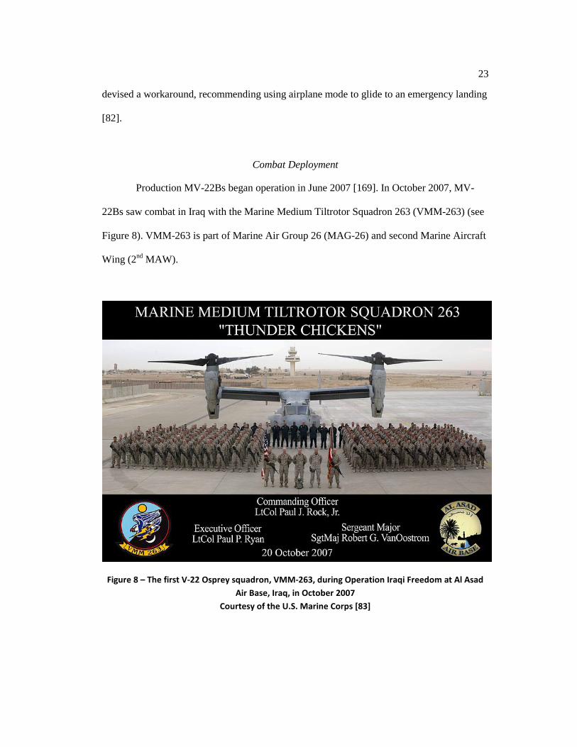
Production MV-22Bs began operation in June 2007 [169]. In October 2007, MV-
22Bs saw combat in Iraq with the Marine Medium Tiltrotor Squadron 263 (VMM-263) (see
Figure 8). VMM-263 is part of Marine Air Group 26 (MAG-26) and second Marine Aircraft
Wing (2nd MAW).
Figure 8 – The first V-22 Osprey squadron, VMM-263, during Operation Iraqi Freedom at Al Asad Air Base, Iraq, in October 2007
Courtesy of the U.S. Marine Corps [83]

24
How Aircraft Work
In this section, the principles of aviation provide the reader with the necessary
background from which to understand aircraft maintenance.
A Boeing MV-22B Osprey tiltrotor can weigh up to 57,000 pounds at takeoff [53].
Later in this chapter, additional details are provided about the MV-22B. Knowledge of the
forces acting on the aircraft: lift, weight, thrust, and drag (see Figure 9) help the reader to
understand how such a heavy machine can fly.
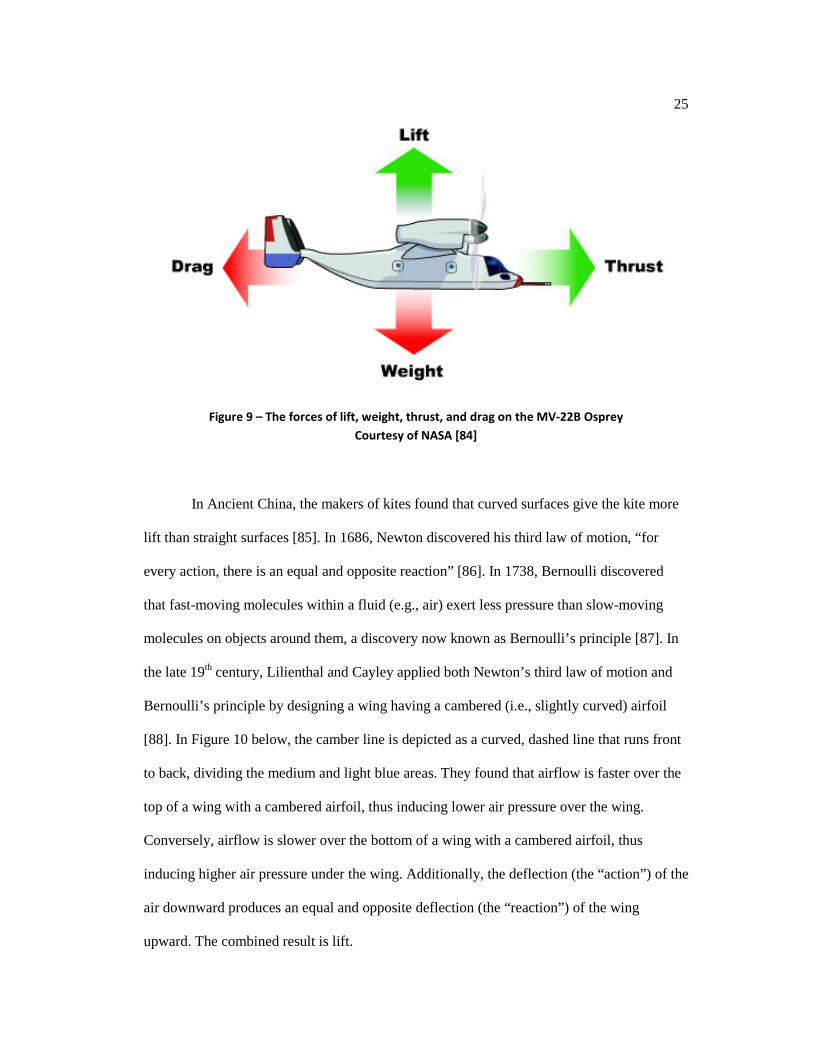
1. Lift is an upward force that is produced by air flowing past the wings or by the
proprotors when the nacelles of the MV-22B are tilted vertically. The force of lift
opposes the force of weight.
2. Weight is downward force resulting from the gravitational force on the mass of the
payload, fuel, equipment, airframe, etc.
3. Thrust is a forward force produced by the proprotors. The force of thrust opposes the
force of drag.
4. Drag is a backward force resulting from either parasitic or induced friction of the
surface of aircraft components (e.g., rivets, antennas, wings, landing gear) with the
air.
25
Figure 9 – The forces of lift, weight, thrust, and drag on the MV-22B Osprey Courtesy of NASA [84]
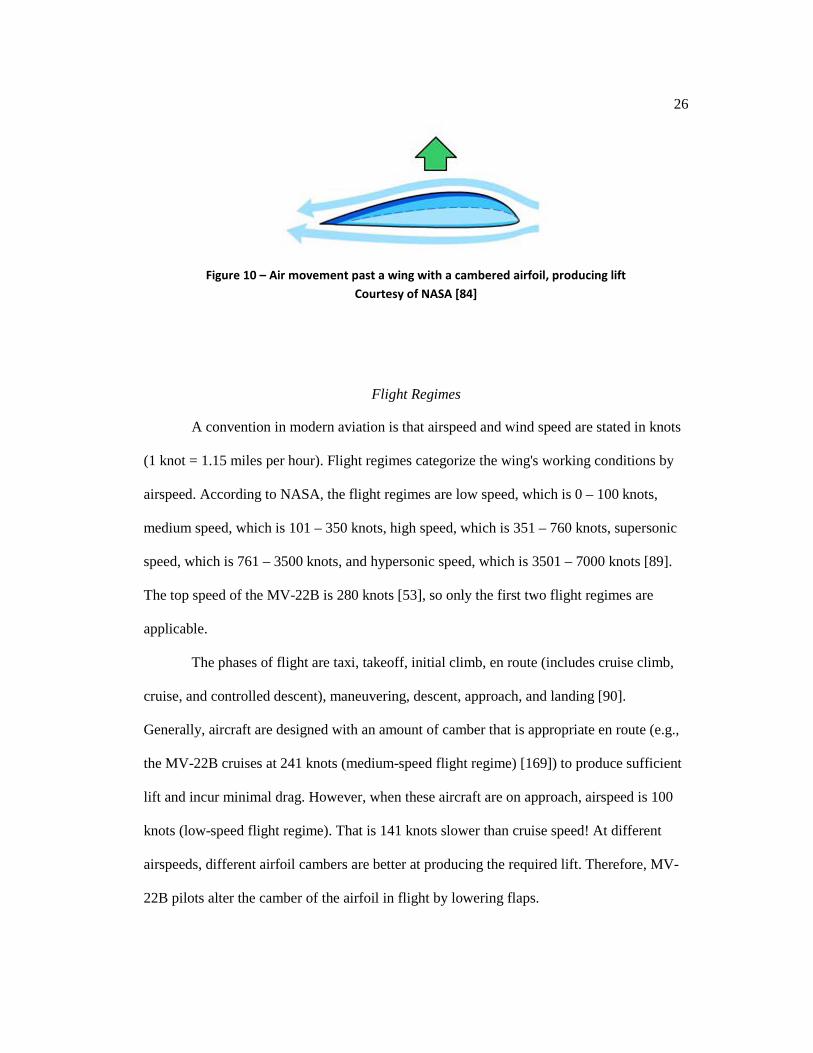
In Ancient China, the makers of kites found that curved surfaces give the kite more
lift than straight surfaces [85]. In 1686, Newton discovered his third law of motion, “for
every action, there is an equal and opposite reaction” [86]. In 1738, Bernoulli discovered
that fast-moving molecules within a fluid (e.g., air) exert less pressure than slow-moving
molecules on objects around them, a discovery now known as Bernoulli’s principle [87]. In
the late 19th century, Lilienthal and Cayley applied both Newton’s third law of motion and
Bernoulli’s principle by designing a wing having a cambered (i.e., slightly curved) airfoil
[88]. In Figure 10 below, the camber line is depicted as a curved, dashed line that runs front
to back, dividing the medium and light blue areas. They found that airflow is faster over the
top of a wing with a cambered airfoil, thus inducing lower air pressure over the wing.
Conversely, airflow is slower over the bottom of a wing with a cambered airfoil, thus
inducing higher air pressure under the wing. Additionally, the deflection (the “action”) of the
air downward produces an equal and opposite deflection (the “reaction”) of the wing
upward. The combined result is lift.
26
Figure 10 – Air movement past a wing with a cambered airfoil, producing lift Courtesy of NASA [84]
Flight Regimes
A convention in modern aviation is that airspeed and wind speed are stated in knots
(1 knot = 1.15 miles per hour). Flight regimes categorize the wing's working conditions by
airspeed. According to NASA, the flight regimes are low speed, which is 0 – 100 knots,
medium speed, which is 101 – 350 knots, high speed, which is 351 – 760 knots, supersonic
speed, which is 761 – 3500 knots, and hypersonic speed, which is 3501 – 7000 knots [89].
The top speed of the MV-22B is 280 knots [53], so only the first two flight regimes are
applicable.
The phases of flight are taxi, takeoff, initial climb, en route (includes cruise climb,
cruise, and controlled descent), maneuvering, descent, approach, and landing [90].
Generally, aircraft are designed with an amount of camber that is appropriate en route (e.g.,
the MV-22B cruises at 241 knots (medium-speed flight regime) [169]) to produce sufficient
lift and incur minimal drag. However, when these aircraft are on approach, airspeed is 100
knots (low-speed flight regime). That is 141 knots slower than cruise speed! At different
airspeeds, different airfoil cambers are better at producing the required lift. Therefore, MV-
22B pilots alter the camber of the airfoil in flight by lowering flaps.
27
Flaperons are on the trailing edge of the wing. On approach, the pilot lowers flaps,
moving the flaperons downward to increase camber; therefore, lift is increased. Conversely,
en route, the pilot neutralizes flaps, moving the flaperons to a neutral position, decreasing
camber. Therefore, drag is reduced, and consequently, airspeed is increased.
Flight Control Surfaces
There are three flight control surfaces on an aircraft that the pilot can use to control
the aircraft’s motion in three-dimensional space about the three principal axes. The MV-22B
uses a fly-by-wire system, which means that flight control surfaces are actuated by servo
(i.e., electronically) rather than by cable. Elevators are moving flight control surfaces on the
empennage (i.e., tail) of the aircraft, and elevators control the pitch of the aircraft. Rudders
are moving flight control surfaces on the empennage that control the yaw of the aircraft.
Note that the MV-22B Osprey has a dual-tailed empennage, so it has two rudders: left and
right. On most airplanes, ailerons are moving flight control surfaces on the wing that control
the roll of the aircraft; however, on the MV-22B, flaperons on the wings combine the
functions of both flaps and ailerons.

28
Figure 11 – Controlling surfaces and aircraft movement about the principal axes of motion Courtesy of Brain et al. [91]
Figure 12 – The MV-22B Osprey’s dual-tailed empennage Courtesy of Marchmann [92]

29
Flight Instruments
The six basic flight instruments provide important information to pilots, especially
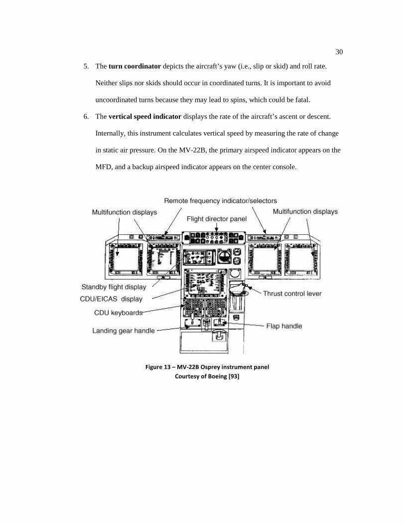
during instrument metrological conditions (IMC) such as clouds or fog. On the MV-22B
Osprey, all primary flight instruments appear on the multifunction displays (MFDs) of the
instrument panel (see Figure 13). Three of the six instruments are so important that backup
instruments appear on the center console. Backup instruments are second instances that the
pilot would use if the MFDs, which display the primary instruments, failed in flight. The six
primary flight instruments are as follows:
1. The airspeed indicator displays the speed at which the aircraft is travelling in the
direction of flight through the surrounding air mass. Internally, this instrument
calculates airspeed from the difference between the dynamic air pressure and the
static air pressure at altitude. On the MV-22B Osprey, the primary airspeed indicator
appears on the MFD (see Figure 15), and a backup airspeed indicator appears on the
center console (see Figure 14).
2. The altimeter is a barometer that measures the altitude of the aircraft by measuring
static air pressure. On the MV-22B, the primary altimeter appears on the MFD, and
a backup altimeter appears on the center console.
3. The attitude indicator (AI) depicts the aircraft’s pitch and roll. It provides spatial
clarity to the pilot even in IMC. On the MV-22B, the primary AI appears on the
MFD. Internally, it uses an attitude and heading reference system (AHRS), which is
a system of three-dimensional magnetometers and accelerometers. A backup AI,
which uses a gyroscope internally, appears on the center console.
4. The heading indicator depicts the aircraft’s magnetic heading. On the MV-22B, the
heading indicator appears on the MFD. Internally, it uses AHRS.
30
5. The turn coordinator depicts the aircraft’s yaw (i.e., slip or skid) and roll rate.
Neither slips nor skids should occur in coordinated turns. It is important to avoid
uncoordinated turns because they may lead to spins, which could be fatal.
6. The vertical speed indicator displays the rate of the aircraft’s ascent or descent.
Internally, this instrument calculates vertical speed by measuring the rate of change
in static air pressure. On the MV-22B, the primary airspeed indicator appears on the
MFD, and a backup airspeed indicator appears on the center console.
Figure 13 – MV-22B Osprey instrument panel Courtesy of Boeing [93]

31
Figure 14 – Pilot’s seat, including instrument panel, of an MV-22B Osprey Adapted from Wikimedia.org [94]
Figure 15 – MV-22B Osprey simulator cockpit Adapted from Bohemia Interactive [95]
Heading Indicator
Primary AI
Primary Altimeter
Primary Airspeed Indicator
Backup AI
Backup Altimeter
Backup Airspeed Indicator
32
Flight Crew
The MV-22B Osprey has a flight crew of three: pilot, copilot, and crew chief.
Additionally, it carries up to 24 passengers. The pilot and copilot each have their own stick,
rudder pedals, and set of MFDs. The MFDs provide access to the cockpit management
system, basic flight instruments, sensor video (e.g., FLIR), communication, navigation,
engine, aircraft configuration, and system status [68]. The crew chief sits in a jump seat on
the forward side of the cabin/cockpit door. On the MV-22B Osprey, there are multifunction
displays for the six basic instruments. The remote frequency indicators and selectors are
used for radio communication and navigation. The flight director panel (see Figure 13)
allows the pilot to select between the two airborne radio communication 210 (ARC-210)
radios for communication, seven intercom stations (i.e., locations), navigation systems, and
autopilot modes. The standby flight display shows the angle of the nacelles, performance of
the engines (i.e., thrust), status of the hydraulic system, angle of the flaps, and fuel
remaining. The engine instrument crew alerting system (EICAS) (see Figure 13) displays
engine instruments: power turbine (NP) rotation, gas generator (NG) spools rotation,
measured gas temperature (MGT), oil pressure, gearbox temperatures, gearbox pressures,
and hydraulic system pressures. The control display unit (CDU) keyboard (see Figure 13)
provides a means for data entry into the cockpit management system. The CDU display
alerts the crew by display of caution and advisory messages and aircraft state indications,
including aircraft health indications.
A thrust lever controls the level of thrust produced by the two engines. The flaps
handle lowers or neutralizes the flaperons, and the landing gear handle raises or lowers the
landing gear.

33
Pilots
The pilot and copilot manipulate the flight controls (e.g., stick and rudder pedals),
engine power settings, engine angle, and aircraft configuration (e.g., flaperons, landing
gear), navigate the aircraft, and communicate with air traffic control (ATC). They monitor
flight instruments during flight. Pilots use their senses and cognitive processes to ensure safe
and timely movement of people, equipment, and supplies. Flight controls (e.g., stick and
rudder pedals), engine power settings, engine angle, and aircraft configuration (e.g.,
flaperons, landing gear) are manipulated. Typically, pilots have offices in the same building
(i.e., the hangar), but not in the same room as the maintainers. Instead, maintainers would
usually be with the aircraft in the hanger bay.
After a flight, the pilot, copilot, or crew chief may write a work order containing a
description of a problem, and then, maintainers examine the work orders [96]. Additionally,
the pilot, copilot, and crew chief typically communicate with maintainers in face-to-face
conversations to clarify the problem and to provide additional information about their
observations.
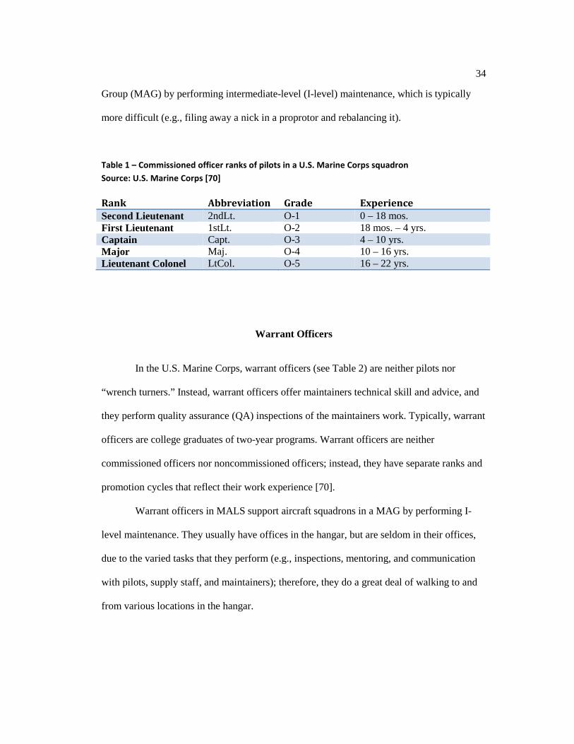
U.S. Marine Corps pilots in the squadron are commissioned officers (see Table 1)
[70]. Typically, commissioned officers are college graduates of four-year programs who
have gone through flight school to become pilots. They could be ranked second lieutenant,
first lieutenant, captain, major, or lieutenant colonel. There are usually more lieutenants in a
squadron than captains, and there are usually more captains than majors. A lieutenant
colonel usually commands the squadron.
Additionally, there are pilots in supporting squadrons called Marine Aviation
Logistics Squadrons (MALS). A MALS supports the aircraft squadrons in a Marine Air
34
Group (MAG) by performing intermediate-level (I-level) maintenance, which is typically
more difficult (e.g., filing away a nick in a proprotor and rebalancing it).
Table 1 – Commissioned officer ranks of pilots in a U.S. Marine Corps squadron Source: U.S. Marine Corps [70]
Rank Abbreviation Grade Experience Second Lieutenant 2ndLt. O-1 0 – 18 mos. First Lieutenant 1stLt. O-2 18 mos. – 4 yrs. Captain Capt. O-3 4 – 10 yrs. Major Maj. O-4 10 – 16 yrs. Lieutenant Colonel LtCol. O-5 16 – 22 yrs.
Warrant Officers
In the U.S. Marine Corps, warrant officers (see Table 2) are neither pilots nor
“wrench turners.” Instead, warrant officers offer maintainers technical skill and advice, and
they perform quality assurance (QA) inspections of the maintainers work. Typically, warrant
officers are college graduates of two-year programs. Warrant officers are neither
commissioned officers nor noncommissioned officers; instead, they have separate ranks and
promotion cycles that reflect their work experience [70].
Warrant officers in MALS support aircraft squadrons in a MAG by performing I-
level maintenance. They usually have offices in the hangar, but are seldom in their offices,
due to the varied tasks that they perform (e.g., inspections, mentoring, and communication
with pilots, supply staff, and maintainers); therefore, they do a great deal of walking to and
from various locations in the hangar.

35
Table 2 – Warrant officer ranks in a U.S. Marine Corps squadron Source: U.S. Marine Corps [70]
Rank Abbreviation Grade Experience Warrant Officer WO W-1 0 – 18 mos. Chief Warrant Officer 2 CWO2 W-2 18 mos. – 4 yrs. Chief Warrant Officer 3 CWO3 W-3 4 – 10 yrs. Chief Warrant Officer 4 CWO4 W-4 10 – 16 yrs. Chief Warrant Officer 5 CWO5 W-5 16 – 22 yrs.
Maintainers
In the U.S. Marine Corps, maintainers are enlisted or noncommissioned officers (see
Table 3) [70]. Usually, they are high school graduates. The crew chief is not only a
crewmember on an MV-22B flight, but also a maintainer. Usually, a crew chief is assigned
to one aircraft; however, there are circumstances when other crew chiefs in the squadron
must fill in. For example, the regular chief for a particular aircraft might be on leave, or may
be in the process of an assignment rotation to another squadron. When present, he or she is
responsible to note any problems that occur during the flight, including startup, taxiing, and
shutdown. Typically, maintainers are in the hangar bay, but not in the same room as the
pilots or warrant officers.
After a flight, the pilot, copilot, or crew chief may write a work order containing a
description of a problem, and then, maintainers examine the work orders [96]. Additionally,
the pilot, copilot, crew chief, and maintainers typically communicate with each other in face-
to-face conversations to clarify the problem and to provide additional information about
their observations. Then, maintainers write a maintenance action form (MAF) from the work
order and from their face-to-face conversation containing the descriptive narrative in Naval
Aviation Logistics Command Management Information System (NALCOMIS).

36
Subsequently, NALCOMIS sends the data to DECKPLATE. Maintainers in MALS support
aircraft squadrons in a MAG by performing I-level maintenance.
Table 3 – Enlisted ranks of maintainers in a U.S. Marine Corps squadron Source: U.S. Marine Corps [70]
Rank Abbrv. Grade Status Experience Private Pvt. E-1 Enlisted 0 – 6 mos. Private First Class PFC. E-2 Enlisted 6 – 9 mos.
Lance Corporal LCpl. E-3 Enlisted 9 mos. – 2 ½ yrs.
Corporal Cpl. E-4 Noncommissioned Officer 2 – 4 yrs. Sergeant Sgt. E-5 Noncommissioned Officer 3 – 6 yrs. Staff Sergeant SSgt. E-6 Noncommissioned Officer 5 – 12 yrs. Gunnery Sergeant GySgt. E-7 Noncommissioned Officer 10 – 16 yrs. Master Sergeant MSgt. E-8 Noncommissioned Officer 12 – 20 yrs. Master Gunnery Sergeant MGySgt. E-9 Noncommissioned Officer 16 – 25 yrs.
Aviation Maintenance
The three levels of maintenance in the U.S. Marine Corps are organizational-level
(O-level), intermediate-level (I-level), and depot-level (D-level) maintenance. O-level
maintenance is the simplest type, and is performed by the aircraft squadron. Generally, an
aircraft squadron performs mostly on-aircraft maintenance and a modest amount of off-
aircraft maintenance. O-level maintenance personnel are organized as in Figure 16 [97].

37
Figure 16 – O-Level maintenance organization in the U.S. Marine Corps Courtesy of Burns [97]
O-level maintenance functions consist of the following functions [97]:
1. Inspections (e.g., preflight checkout)
2. Servicing (e.g., inflating the tires, cleaning the bugs off the windshield)
3. Handling (e.g., tugging the aircraft to or from the hangar)
4. On-equipment corrective and preventive maintenance (e.g., removing and replacing
a defective ARC-210 radio)
5. Compliance with technical directives (TDs)
6. Record keeping and reports preparation
7. Operating aeronautical equipment (AE)
8. Supporting the reliability-centered maintenance (RCM) program
38
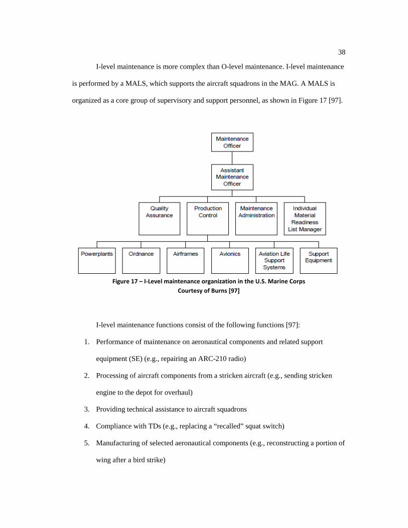
I-level maintenance is more complex than O-level maintenance. I-level maintenance
is performed by a MALS, which supports the aircraft squadrons in the MAG. A MALS is
organized as a core group of supervisory and support personnel, as shown in Figure 17 [97].
Figure 17 – I-Level maintenance organization in the U.S. Marine Corps
Courtesy of Burns [97]
I-level maintenance functions consist of the following functions [97]:
1. Performance of maintenance on aeronautical components and related support
equipment (SE) (e.g., repairing an ARC-210 radio)
2. Processing of aircraft components from a stricken aircraft (e.g., sending stricken
engine to the depot for overhaul)
3. Providing technical assistance to aircraft squadrons
4. Compliance with TDs (e.g., replacing a “recalled” squat switch)
5. Manufacturing of selected aeronautical components (e.g., reconstructing a portion of
wing after a bird strike)

39
6. Performance of on-aircraft maintenance (e.g., rust remediation)
7. Operating AE
8. Supporting the RCM program
D-level maintenance is the most complex level of maintenance. D-level maintenance
is performed at the depot on components requiring major overhaul [97]. At the depot,
government civilian personnel work in conjunction with OEM contractors at naval industrial
establishments. D-level maintenance consists of the following [97]:
1. Rebuilding of engines, components, and SE (e.g., a complete engine overhaul)
2. Compliance with TDs
3. Modification of aircraft, engines, and SE (e.g., retrofitting with an upgraded
gearbox)
4. Manufacturing or modification of components (e.g., improved wing root fairings)
5. Technical and engineering assistance by field teams about AE and RCM

40
Chapter 3
Literature Review
The literature is reviewed of the following components: macrocognition, a
comparison of the relative strengths and weaknesses of machine and people, condition-based
maintenance, hard/soft information fusion, JDL data fusion process model, CBM+ and the
JDL model, Hard/Soft information fusion in condition monitoring in relation to levels of the
JDL data fusion process model, and alternative information fusion frameworks.
Macrocognition
Macrocognition is a collection of mental processes and functions [98], including
information processing within the person’s mind [99]. Cacciabue and Hollnagel said,
“Macrocognition is a collection of cognitive functions and processes that describes how
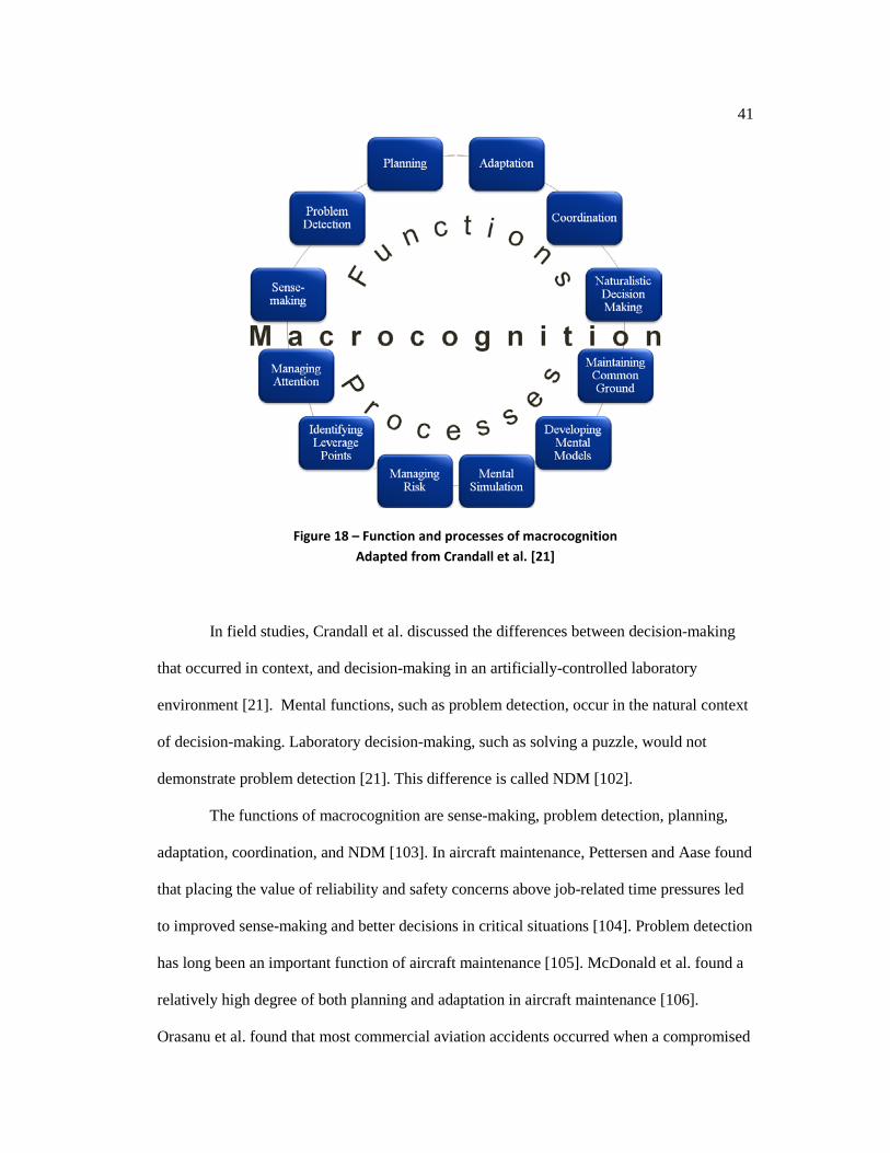
people think in the performance of their work in its natural settings” [100]. In the framework
of macrocognition (see Figure 18), mental functions are supported by mental processes [21].
Aircraft maintainers employ cognitive functions and processes in the performance of their
work [101].
41
Figure 18 – Function and processes of macrocognition Adapted from Crandall et al. [21]
In field studies, Crandall et al. discussed the differences between decision-making
that occurred in context, and decision-making in an artificially-controlled laboratory
environment [21]. Mental functions, such as problem detection, occur in the natural context
of decision-making. Laboratory decision-making, such as solving a puzzle, would not
demonstrate problem detection [21]. This difference is called NDM [102].
The functions of macrocognition are sense-making, problem detection, planning,
adaptation, coordination, and NDM [103]. In aircraft maintenance, Pettersen and Aase found
that placing the value of reliability and safety concerns above job-related time pressures led
to improved sense-making and better decisions in critical situations [104]. Problem detection
has long been an important function of aircraft maintenance [105]. McDonald et al. found a
relatively high degree of both planning and adaptation in aircraft maintenance [106].
Orasanu et al. found that most commercial aviation accidents occurred when a compromised

42
flight plan was not replanned [107], and replanning depends heavily on problem detection
[21]. Taylor et al. improved dependability and safety by training maintainers in teamwork
coordination skills [108]. Decision-making in context, or NDM [102], is an important
function of aircraft maintenance [49]. Experience of the maintainer was also shown to be an
important factor in decision-making [109].
The processes of macrocognition are managing attention, identifying leverage
points, managing risk, mental simulation, developing mental models, and maintaining
common ground [103]. Klein et al. found that managing attention was an important process
in problem detection [110]. Zsambok et al. “argued that problem solving is nonlinear and
moves forward by identifying leverage points” [102]. Gill and Shergill cited risk
management as a key factor in the safety practices of aircraft maintenance [111]. Johnson
and Satchwell improved technical performance of apprentice maintainers through the use of
“runnable” functional flow diagrams, a form of mental simulation [112].
Machines Need People to ... but People Need Machines to ...
Several challenges arise when sharing cognitive functions with information
technology. For example, since the advent of the flight management system (FMS), a
challenge has been the lack of instant feedback from the FMS as there would be if the pilot
were using stick and rudder [113].
In the words of Shneiderman: “People are not machines and machines are not
people” [114]. By stating the obvious, Shneiderman offers an entry point for considering the
fundamental differences between humans and silicon information systems [115]. Humans
differ from machines, and their abilities have fundamentally different strengths [115].
Humans excel at cognitive abilities: adaptation, inductive reasoning, and judgment [116]. In

43
comparison, machines are better at storing large series of data, responding quickly,
performing repetitive tasks, reasoning deductively, and doing fast, accurate mathematical
computations. Therefore, the cognitive level is where a human-machine collaborative
approach to fusion could potentially add the greatest value.
The relationship between human and machine is asymmetric, with agency unevenly
distributed across human and machine—a significant difference [12]. Effective designs are
those that exploit the asymmetric abilities of human and machines [117], as described by
Fitts [116]. Artificially intelligent machines are entities that are actants in human-computer
interaction. An actant is an entity that has been granted permission by humans to initiate an
action [118] by humans. In contrast to a machine-centered approach to systems design,
practitioners in cognitive systems engineering hold to a human-centered approach [52],
shown in Table 4, as an effective way to exploit the asymmetric abilities of human and
machine [116]. The table was adapted from Hoffman et al.’s [52] response to Fitts’ list
[116], which they called the “Un-Fitts list”.
Table 4 – Machines need people to ... but people need machines to ... Adapted from the “Un-Fitts list” of Hoffman et al. [52] and Bernardo [119]
Machines People
Are limited in that ...
And need people to ... Are not limited in that ...
But need machines to ...
Sensitivity to context is … Low To keep them aligned to
the context High To keep them informed of context
Sensitivity to change is … Low
To keep them stable given the variability and change inherent in the world
High To align and repair their perceptions because they rely on mediated stimuli
Adaptability is … Low To repair their ontologies High To effect positive change
following situation change Context-awareness is …
Low To keep the model aligned with the world High
To computationally instantiate their models of the world

44
Condition-Based Maintenance Plus
Maintenance-induced (iatrogenic) problems are a significant cause of aircraft
mechanical problems [44]. Avoidance of maintenance-induced problems constitutes a strong
rationale for CBM+, in the safety-critical domain of aviation. CBM+ is a maintenance
strategy that relies on evidence to indicate states of deterioration, meaning that the decision
to disassemble an aircraft component is based upon evidence rather than upon a specified
time interval (e.g., 1 year) or use interval (e.g., engine hours) [120]. In aircraft that have fault
reporting capability, the aircraft’s state can be monitored, which is called condition
monitoring, and CBM+ can be utilized to monitor the state of such aircraft.
CBM+ became feasible in the 1980s when low-cost microprocessors became widely
available [121]. In contrast to CBM+ , previous maintenance strategies were corrective
maintenance, time-based, and use-based maintenance (see Table 5) [122]. Corrective
maintenance is a strategy described by the adage, “If it isn’t broken, don’t fix it.” As a
maintenance strategy, it has been in existence since the beginning of the industrial era, and it
is neither proactive nor predictive [30]. Time- and use-based maintenance involves “setting a
quantifiable standard relating to the root cause of concern and implementing a maintenance
program to control the root cause” [122] (e.g., turbine with a mandatory time between
overhaul (TBO) of 5,000 hours, change of oil every 3,000 miles for an automobile). As a
maintenance strategy, it has been in existence since the early 1900s.
Corrective, time-, and use-based maintenance strategies have several weaknesses.
The selection of the time or use interval for maintenance is based on assumptions or data
about how long a mechanical system can be operated before it “needs” intervention. Clearly,
there is no perfect interval or use-metric. If the time or use interval is selected to be too long,
then mechanical failures can occur, possibly causing serious problems. For example,

45
changing the timing belt on a vehicle is critical, since the vehicle will not operate with a
broken timing belt. However, the choice of when to make the change must be commensurate
with an accurate assessment of when such change is justifiable. On the other hand, selecting
a time or use interval that is too short results in undue maintenance performed, leading to
unnecessary operational maintenance cost and to maintenance-induced (iatrogenic)
problems.
Table 5 – Maintenance strategies by date of origination, and by proactive and predictive nature
Maintenance Strategy Mnemonic Proactive or Predictive Nature
Date of Origination
Corrective maintenance
“If it isn’t broken, don’t fix it”
Neither proactive nor predictive [30]
Beginning of the industrial era
Time- and use-based maintenance
Time between overhaul or parts expiration dates
Proactive, but not predictive [30]
Early 1900s
Condition–based maintenance
“’Check engine’ light on steroids”
Both proactive and predictive [122]
1980s
CBM+ has undergone an information explosion [123] due to advances in sensor
technologies [124] such as the proliferation of high-capacity, low-cost electronics [125] (i.e.,
Moore’s Law [126]), and advances in signal processing methods [127]. The sheer volume of
data collected from monitoring the condition of complex machines has become a big data
problem [128]. For example, as of this writing, Naval Air Systems Command (NAVAIR)
already has over ten terabytes of structured and unstructured aircraft maintenance data.
According to Moubray, a primary goal (see Figure 19) in CBM+ is to increase the
time available to act. The underutilization of condition monitoring data is an obstacle to
achieving this goal. The use of CBM+ increases flight safety and mission readiness, and it
decreases the cost of maintenance operations [122].

46
Figure 19 – The performance-failure (P-F) curve
Adapted from Moubray [30]
CBM+ has six major challenges. First, there is a relatively high failure rate of sensors
compared to the machines they monitor; hence, false alarm rates tend to be elevated [123]. A
consequence is that operator trust in automation (e.g., the “check engine” light in a car) is
slow to recover following false alarms[129]. Second, the training of pattern recognition or
machine learning algorithms tend to have the following problems: learning the precursors to
failure require a lot of effort [130], over-learning is detrimental [131], and it is difficult to
find training data of the mechanical faults necessary for good calibration [132]. Third, there
is a high cost associated with driving machines to failure to obtain appropriate training data
[30]. Fourth, machines tend to have difficulty in understanding the context in which
observations are made [52]. Fifth, the complexity is high for systems of many-to-many maps
between failure indicators (e.g., high temperature, increased vibration) and failure
mechanisms [123][133][134]. Sixth, CBM+ has undergone an information explosion, leading
to such a quantity that it is difficult to analyze [123]. A theme of this research is to overcome
some of these obstacles by integrating other sources of information—human sources.

47
Hard/Soft Information Fusion
Lambert[135] described information fusion research as being at a crossroads [136].
He stated, “The data fusion community [is] beginning to exceed its historical roots in sensor
fusion” [135]. He identified the next big step in fusion research, “requiring greater
development of automated situation and impact assessments and more appropriate
integration with humans engaged in fusion activity” [135].
The literature is extensive on techniques to fuse data from electronic sensors, but
work on fusing observations from humans with data from electronic sensors (i.e., hard/soft
fusion) is developing [137]. Although hard/soft information fusion has only recently been
recognized as a research area, extensive literature is emerging in some domains. Since 2002,
there have been several papers written about level 5 of the JDL data fusion process model
[138][139][140], a book on human-centered fusion [1], dissertations in the domains of
situation awareness [2], and sense-making [141], and several noteworthy papers in the
domains of intelligence [142],[143],[144], theory[3], risk analysis [145],[146],[147],[5], and
collaborative sensing[148]. However, such literature is just emerging for the condition
monitoring of aircraft. The current effort is the first to study hard/soft information fusion in
the domain of the condition monitoring of aircraft.
Hall and Jordan characterized the inputs to the hard/soft information fusion process
as belonging to three main groups, which are referred to as spaces: sensor space (S-space),
human space (H-space), and information space (I-space) [1]. The S-space consists of
traditional data sensors, such as thermistors, accelerometers, and various transducers. The H-
space consists of human observers. The I-space augments direct human observations and
data from electronic sensors with historical information, which may be stored in databases,
government publications, news articles, or on the Internet in the form of blogs. In aviation
48
maintenance, the I-space includes maintenance logs, service bulletins, and other mechanical
notes regarding a type of aircraft and its major components. I-space information would come
from the manufacturer, the Federal Aviation Administration (FAA), an organization’s
maintenance personnel, or the Internet.
Traditionally, CBM+ involves equipping machinery with electronic sensors to gather
data for diagnostic analysis. While these electronic sensors provide valuable data, they lack
human cognition, which excels at multisensory pattern recognition, natural language [149],
intuition [150], versatility, inductive reasoning, judgment [116], and decision-making. This
dissertation focuses on decision-making because of its key role in aviation maintenance.
Human strengths provide an opportunity to utilize a dynamic resource—people acting as soft
sensors. The fusion of human observation and sensor data create a fuller picture of
machinery condition [140]. The key is humans making context-based assessments of what
the machine is doing (conditions under which it is operating, etc.) when the observations are
made [151].
For monitoring complex machinery, such as aircraft, a CBM+ system focuses on
real-time collection of physical data (e.g., vibrations, temperature, etc.) using hard sensors
and performing signal processing, pattern recognition and other operations to provide a
current assessment of the condition of the monitored system. Sensor data flows regularly
from aircraft to information systems such as Optimized Organizational Maintenance
Activity (OOMA), Logistics Analysis, and Technical Evaluation (DECKPLATE), and Joint
Deficiency Reporting System (JDRS). The cognitive level (i.e., higher-level fusion) is where
humans add value; the aircraft maintainer would contrast and compare his senses now to his
senses on a previous maintenance task (e.g., the sound of the engine running, the odors in
and around the aircraft, visual changes, and vibration through the airframe) [105].

49
Challenges in estimating the state (condition) of aircraft by using hard and soft data
sources would be the infrequency, tasking, inaccuracy, errors, high variance, and bias
associated with human observation [152]. On the other hand, trained observers may function
more efficiently than electronic sensors when challenges in the observing environment result
in electronic sensors being uncertain, incorrect, and inconclusive. “There [is] no substitute
for a good sensor that is appropriate to the situation of interest: No amount of fusion of
multiple poor sensors can substitute for an effective sensor” [140]. Therefore, if the right
“sensor” is a human, then human observation should be used as an information source in the
fusion process.
As outlined above, the sources of information are the built-in test equipment and
human observation in the descriptive narratives and the corrective action narratives. As
Svensson stated, “information fusion incorporates techniques for the collection of multiple
sensor resources in order to gather more accurate and reliable information” [153]. The fusion
of information from both of the above sources in the activity of maintenance of aircraft is
important to the safety of the pilot, crew, and others associated with the flight.
JDL Data Fusion Process Model
The JDL data fusion process model (see Figure 20) is a functional information
fusion framework [8] that contains many important, relevant concepts. Since 1988, the JDL
data fusion process model has served as a framework for information fusion research. In
large part, it was originally developed for military domain applications such as air-to-air
defense, surface-to-air defense using radar, and anti-submarine warfare using sonar. In 2002,
it was revised by Blasch and Plano to consist of six high-level processes [138].

50
Figure 20 – The JDL data fusion process model Courtesy of Hall et al. [140]
The JDL Model and CBM+
According to the U.S. Army Aviation and Missile Research, Development and
Engineering Center (AMRDEC), the following definitions apply to CBM+ [154]:
“A condition indicator is a measure of detectable phenomena, derived from sensors, that shows a change in physical properties related to a specific failure mode or fault.”
“A health indicator is an indicator for needed maintenance resulting from the combination of one or more condition indicator values.”
Using the definitions above, Table 6 shows comparison of original interpretation
(e.g., air-to-air defense) of the JDL data fusion process model to the interpretation for
CBM+.
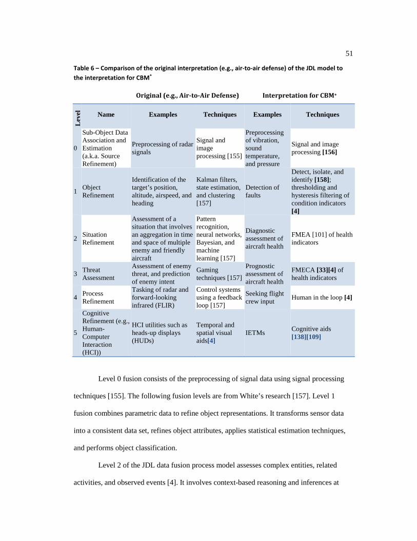
51
Table 6 – Comparison of the original interpretation (e.g., air-to-air defense) of the JDL model to the interpretation for CBM+
Original (e.g., Air-to-Air Defense) Interpretation for CBM+
Lev
el
Name Examples Techniques Examples Techniques
0
Sub-Object Data Association and Estimation (a.k.a. Source Refinement)
Preprocessing of radar signals
Signal and image processing [155]
Preprocessing of vibration, sound temperature, and pressure
Signal and image processing [156]
1 Object Refinement
Identification of the target’s position, altitude, airspeed, and heading
Kalman filters, state estimation, and clustering [157]
Detection of faults
Detect, isolate, and identify [158]; thresholding and hysteresis filtering of condition indicators [4]
2 Situation Refinement
Assessment of a situation that involves an aggregation in time and space of multiple enemy and friendly aircraft
Pattern recognition, neural networks, Bayesian, and machine learning [157]
Diagnostic assessment of aircraft health
FMEA [101] of health indicators
3 Threat Assessment
Assessment of enemy threat, and prediction of enemy intent
Gaming techniques [157]
Prognostic assessment of aircraft health
FMECA [33][4] of health indicators
4 Process Refinement
Tasking of radar and forward-looking infrared (FLIR)
Control systems using a feedback loop [157]
Seeking flight crew input Human in the loop [4]
5
Cognitive Refinement (e.g., Human-Computer Interaction (HCI))
HCI utilities such as heads-up displays (HUDs)
Temporal and spatial visual aids[4]
IETMs Cognitive aids [138][109]
Level 0 fusion consists of the preprocessing of signal data using signal processing
techniques [155]. The following fusion levels are from White’s research [157]. Level 1
fusion combines parametric data to refine object representations. It transforms sensor data
into a consistent data set, refines object attributes, applies statistical estimation techniques,
and performs object classification.
Level 2 of the JDL data fusion process model assesses complex entities, related
activities, and observed events [4]. It involves context-based reasoning and inferences at

52
higher than level 1 of the JDL data fusion process model. The performance of automated
reasoning is a key challenge, and relevant techniques come from the field of artificial
intelligence.
Level 3 fusion processing computes a prognosis and assesses impacts. Techniques
similar to those in level 2 are utilized. In essence, level 3 fusion seeks to identify alternative
consequences of the current situation and evaluate those alternatives to select the most likely
consequence of the current situation.
Level 4 fusion is a meta-process, i.e., a process modeling other processes. It
involves real-time control, process performance management, process improvement,
requirements management, and autonomous control.
Level 5 fusion optimizes human-computer collaboration [138]. There are at least
two examples of level 5 fusion research at the Pennsylvania State University. First, “The
Cave” is a 3-D full-immersion visualization environment at the NC2IF in the College of IST.
[18].Dr. Richard Tutwiler is the deputy director of NC2IF. The project’s goal is to improve
data analysis by “conservation of analyst attention,” i.e., it lets the analyst focus on analysis
and interpretation rather than the otherwise laborious task of information searching.
Second, Dr. Mark Ballora’s Rhythms of the Universe is a sonification of scientific
data sets about celestial phenomena, which is used as an educational tool for the visually
impaired as well as for the general population [20]. Dr. Ballora is a Professor of Music at
Penn State.
The JDL data fusion process model is a good functional information fusion
framework. However, in the literature, a gap exists on applying the JDL model to hard/soft
information fusion for the condition monitoring of aircraft.

53
Organizing the Literature on Hard/Soft Fusion in Condition Monitoring into Levels of the JDL Data Fusion Process Model
The hard/soft fusion literature on condition monitoring is summarized by level
according to the JDL data fusion process model [136]. Galar et al.[28],[159],[160] and
Reiger [27] made no mention of JDL data fusion process model; however, for the purpose of
comparison, all are organized into corresponding levels of the JDL data fusion process
model. The distinction between levels of the JDL data fusion process model does not imply
that levels are decoupled. On the contrary, in real-world information fusion systems,
information processing is coordinated across many levels[4].
The hard/soft literature provides little mention of level 0 and level 1 processing
because these levels deal primarily with source pre-processing (e.g., signal and image
processing, feature extraction, coordinate transformations) for level 0 and state estimation
(e.g., Kalman filtering, feature-based pattern recognition) for level 1. While there are level 0
and level 1 analogs for soft data processing (e.g., text extraction, meta-data generation,
image to text transformations, etc.), these are not the primary focus of hard/soft fusion
processing.
Level 2/3 Human-Influenced Diagnostics and Prognostics
Level 2/3 human-influenced diagnostics and prognostics are primarily machine
based, but have been enhanced to benefit from some human intervention. Reiger [27]
proposed that people be employed to increase the resiliency of automated (i.e., machine-
based) diagnostics to unexpected conditions. He studied the identification of abnormal
conditions and implications in a control system using automated, distributed reasoning
amongst multiple software agents.

54
Reiger’s case studies involve the monitoring of industrial processes: electric power
substations, chemical facility reactors, and hazardous facility climate control[27]. The
unexpected conditions introduced were sabotage, sensor failure, and equipment failure. The
manifestations of unexpected conditions in automated systems create competing goals that
are difficult to resolve without human intervention. As shown in Table 7, Reiger posited that
systems benefit from improved resilience due to the human cognitive ability to adapt and
reason.
Reiger acknowledged that human contribution to resilience could be either
beneficial or detrimental. Therefore, he emphasized the importance of training, because
“[the] system … will be no better than the competency and proficiency of the least capable
individual” [27].
Table 7 – Literature on hard/soft fusion in condition monitoring organized into levels of the JDL model Source: Bernardo [136]
Levels Name Author Findings
2/3 Human-influenced diagnostics and prognostics
Reiger [27] Systems could benefit from improved resilience due to the human cognitive ability to adapt.
2/3/5
Integrated machine- and human-based diagnostics and prognostics
Galar et al. [28][159][160]
A more complete, accurate assessment of the condition led to better diagnostics and prognostics. Consequently, safety and reliability were increased, and life-cycle maintenance costs were reduced.
5 Human information processing Nilsson et al. [3] Hard/soft information fusion emerges from the
interaction between machines and humans.
Level 2/3/5 Integrated Machine- and Human-Based Diagnostics and Prognostics
In level-2/3/5 integrated machine- and human-based diagnostics and prognostics,
functions are shared across machine and human. No single level of the JDL data fusion
55
process model encompasses integrated machine- and human-based diagnostics and
prognostics; instead, such systems are comprised of two components of equal importance.
The machine-based component belongs to levels 2 and 3, and the human-based component
belongs to level 5. Together, the two components comprise a level-2/3/5 integrated machine-
and human-based diagnostics and prognostics fusion system.
In a series of three papers, Galar et al. promoted a hybrid, data-driven, and
phenomenological approach to fusion in order to aid the condition-based maintenance of
railway assets (e.g., locomotives, track components, interchanges) [28],[159],[160]. In a
Machinery Information Management Open System Alliance (MIMOSA) framework,
measurements were collected from electronic sensors. Maintainers’ notes contain free-text
descriptions of faults and actions performed. Each maintainer may describe the same
phenomenon differently; therefore, semantic analysis, which is JDL level 0 and level 1
processing for soft data, is essential. Galar et al. reported that the context mined from the
maintainers’ notes benefitted diagnostics and prognostics analyses, and it resulted in a more
complete, accurate assessment of the condition of railway assets[160]. Consequently, safety
and reliability of railway assets were increased, and life-cycle maintenance costs were
reduced.
Level 5 Human Information Processing
Nilsson et al. explored the role of human information processing in level-5 fusion
[3]. They proposed the employment of people as active participants in human-machine
distributed cognition. They found that hard/soft information fusion emerges from the
interaction between machines and humans. They identified the processes of human cognition
as fusion resources.

56
Although Nilsson et al. chose a case study in maritime surveillance [3], the same
concepts could be applied to the condition monitoring of aircraft. For example, some aircraft
have more than one ground system to aid in diagnostic and prognostic analyses of aircraft
components (e.g., engines, transmissions, and avionics). Using the cognitive functions and
processes involved in human information processing, engineers and maintainers could work
in cooperation to identify readings, called features, on those ground systems to corroborate
the tracking of risks present on the aircraft, even before they may become faults.
Alternative Information Fusion Frameworks
Other frameworks address the processes of information fusion. Hall et al.
categorized the frameworks into two broad categories: information fusion and decision-
making frameworks [161]. One of the most well-known is the Observe-Orient-Decide-Act
(OODA) loop [162][163][164][165]. Each of these frameworks has their own advantages
and disadvantages concerning information fusion.
The research literature on information fusion is vast [166][151][4]. It is beyond the
scope of this literature review to cover these extensive works in detail. A summary of
alternative fusion models in Table 8 shows the variation in fusion processes and how they
might be used in decision-making. Note that the list is non-exhaustive. See Hall et al. for an
excellent discussion of information fusion frameworks [161].
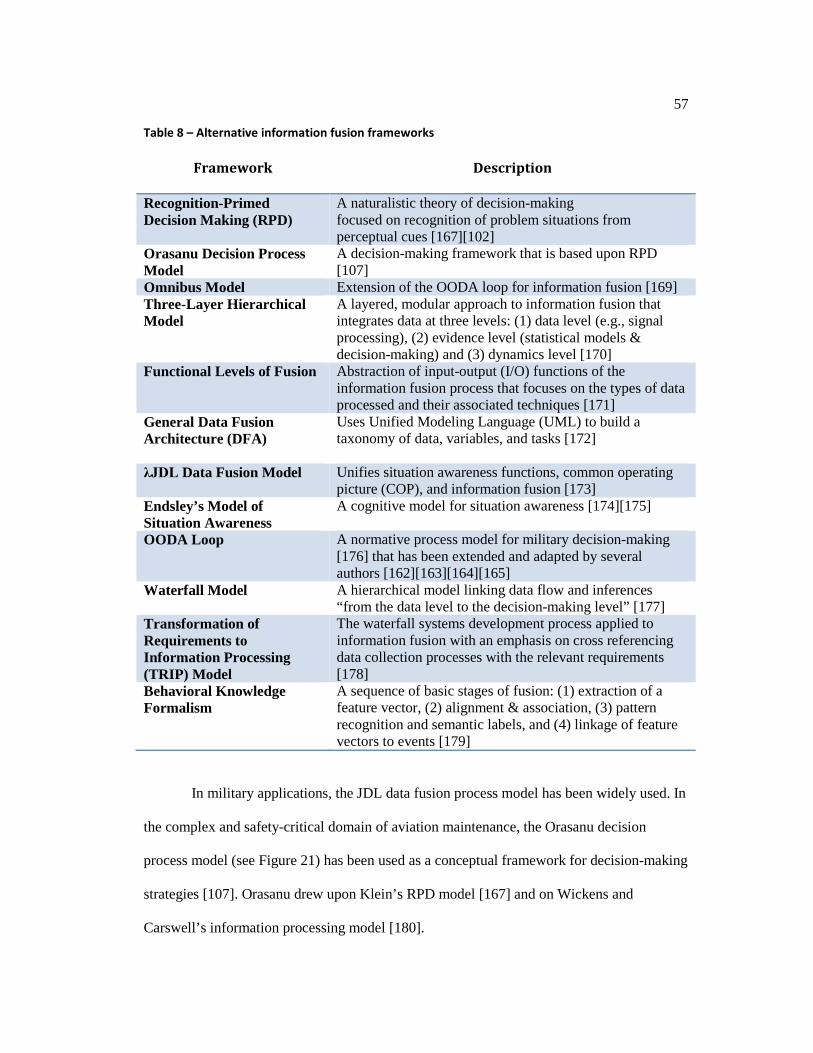
57
Table 8 – Alternative information fusion frameworks
Framework Description
Recognition-Primed Decision Making (RPD)
A naturalistic theory of decision-making focused on recognition of problem situations from perceptual cues [167][102]
Orasanu Decision Process Model
A decision-making framework that is based upon RPD [107]
Omnibus Model Extension of the OODA loop for information fusion [169] Three-Layer Hierarchical Model
A layered, modular approach to information fusion that integrates data at three levels: (1) data level (e.g., signal processing), (2) evidence level (statistical models & decision-making) and (3) dynamics level [170]
Functional Levels of Fusion Abstraction of input-output (I/O) functions of the information fusion process that focuses on the types of data processed and their associated techniques [171]
General Data Fusion Architecture (DFA)
Uses Unified Modeling Language (UML) to build a taxonomy of data, variables, and tasks [172]
λJDL Data Fusion Model Unifies situation awareness functions, common operating picture (COP), and information fusion [173]
Endsley’s Model of Situation Awareness
A cognitive model for situation awareness [174][175]
OODA Loop
A normative process model for military decision-making [176] that has been extended and adapted by several authors [162][163][164][165]
Waterfall Model A hierarchical model linking data flow and inferences “from the data level to the decision-making level” [177]
Transformation of Requirements to Information Processing (TRIP) Model
The waterfall systems development process applied to information fusion with an emphasis on cross referencing data collection processes with the relevant requirements [178]
Behavioral Knowledge Formalism
A sequence of basic stages of fusion: (1) extraction of a feature vector, (2) alignment & association, (3) pattern recognition and semantic labels, and (4) linkage of feature vectors to events [179]
In military applications, the JDL data fusion process model has been widely used. In
the complex and safety-critical domain of aviation maintenance, the Orasanu decision
process model (see Figure 21) has been used as a conceptual framework for decision-making
strategies [107]. Orasanu drew upon Klein’s RPD model [167] and on Wickens and
Carswell’s information processing model [180].

58
Figure 21 – The Orasanu decision process model Courtesy of Orasanu [181]
Summary
In summary, the following points were made in the literature review:
1. Maintenance of aircraft is costly; time-based and use-based methods lead to
high maintenance operations costs and iatrogenic failures.
2. There is a rapid movement towards CBM+ via deployment of sensors and semi-
automated processing of sensor data (via machine learning, artificial
intelligence, etc.)
3. While increasingly effective, CBM+ currently utilizes only hard sensor data and
does not incorporate human observations (i.e., soft data) to provide contextual
interpretation of sensor data. Because context is important in NDM, human
59
observation provides an opportunity to improve diagnostics, leading to better
outcomes.
4. Research conducted in the military situation awareness domain has provided
evidence that the combination of human (i.e., soft sensor) observation and hard
(i.e., physical sensor) data can provide more accurate, and timely inferences
compared to those using either soft data or hard data alone.
5. It was hypothesized that the combination of hard and soft data has the potential
to improve CBM+ for aircraft operations.
6. The following three gaps exist:
a. Cognitive and functional frameworks have not been applied to hard/soft
information fusion of CBM+ data for aircraft operations. In Chapter 4,
this gap was addressed by the following:
i. Applying a functional framework to hard/soft information
fusion for the condition monitoring of aircraft
ii. Applying a cognitive framework to hard/soft information fusion
for the condition monitoring of aircraft
b. The research problem at hand involved a combination of sensor data,
human observations, human decisions, and inferences. Therefore, it was
necessary to develop a research design in Chapter 5 that involved a
combination of analytical and interpretive techniques.
c. This application involved the use of hard sensor data and human
observations focused on decision-making (e.g., related to aircraft
maintenance). There has been no literature on the application of hard
and soft fusion techniques applied specifically to CBM+ of aircraft. For
this application, the soft data involves both observations of aircraft

60
conditions and contextual information that would modulate the
interpretation of the hard sensor data. Moreover, the hard and soft data
are utilized for JDL level-3 processing (i.e., the identification of
potential hypotheses regarding impending mechanical failures and
evaluation of those hypotheses). Thus, it was necessary to formulate a
research approach to address this application in Chapter 6.
61
Chapter 4
Cognitive and Functional Frameworks
Previous research has left a gap: the lack of the application of cognitive and
functional frameworks to hard/soft information fusion for condition monitoring of aircraft.
These frameworks are applied to the domain, and they are informed by other conceptual
frameworks. The cognitive framework is informed by the research of Orasanu [181]; Klein
[168]; Wickens and Carswell [180]; and Crandall, Klein, and Hoffman [21]. The functional
framework is informed by the research of Blasch[139], Hall et al.[140], and Bernardo [136].
Cognitive Framework for Hard/Soft Information Fusion in the Condition Monitoring of Aircraft
Aviation maintenance is complex and safety critical. In Chapter 3, The concept of
macrocognition of Crandall et al. [21] and the decision process model of Orasanu [181] were
reviewed. Cacciabue and Hollnagel said, “Macrocognition is a collection of cognitive
functions and processes that describes how people think in the performance of their work in
its natural settings” [100]. In the context of aviation maintenance, macrocognition can be
viewed as cognitive functions and processes within the aircraft maintainer’s mind.
In field studies, Crandall et al. discussed the differences between decision-making
in context, and decision-making in an artificially-controlled laboratory environment [21].
Mental functions, such as problem detection, which are relevant to aircraft maintenance,
occur in the natural context of decision-making. They found that decisions in the field were
often primed by the recognition of the problem situation as something similar to what was
experienced in the past. Klein called this recognition primed decision-making (RPD) [167].
Supporting Klein’s model, Evans said, “As a pilot/maintainer, you never check an aircraft

62
component better than those that you have seen broken before. Once you have seen it
broken, the next time you can recognize the issue and solution much more quickly” [182].
The Orasanu decision process model [181] (see Figure 21) is a conceptual
framework for decision-making strategies. Orasanu drew upon Klein’s RPD model [168]
and on Wickens and Carswell’s information processing model [180]. By adapting the
Orasanu decision process model and Klein’s macrocognition framework, a cognitive
framework is applied to hard/soft information fusion in CBM+. In Figure 22, the cognitive
framework has been informed by Orasanu decision process model, Wickens and Carswell’s
information processing model, and Klein’s macrocognition.
Figure 22 –Cognitive framework for hard/soft fusion in the condition monitoring of aircraft Adapted from Orasanu [181]; Klein [168]; Wickens and Carswell [180]; and Crandall, Klein, and
Hoffman [21]
63
Aviation maintenance is safety critical and complex. In selecting a decision-making
strategy, maintainers often juggle competing priorities of safety against the organizational
unit’s mission capability goals (e.g., completing a landing gear inspection during the middle
of the night before the aircraft’s already scheduled dawn mission). One decision-making
strategy that maintainers employ is the use of heuristics (i.e., rules of thumb), if they fall
within guidance of the maintenance manuals. Time pressure, stress, or both are a rationale
for using heuristics for decision-making. Therefore, a focus of this framework is on the
differences between “rule available” (i.e., heuristics) and “multiple options available.”
The functions of macrocognition are sense-making, problem detection, planning,
adaptation, coordination, and naturalistic decision-making. The processes constituting
macrocognition are managing attention, identifying leverage points, managing risk,
performing mental simulations, developing mental models, and maintaining common ground
[25]. At the top level of Figure 22, faults, represented by built-in test (BIT) codes [183], and
human observations regarding an aviation maintenance problem are present. The maintainer
initiates problem detection by asking, “What is the problem?” Then, he or she attempts to
manage risk by asking, “How much time is available to fix the problem? How risky is the
situation?” For example, Pettersen and Aase found that maintainers balance safety concerns
with job-related time pressures [104]. Gill and Shergill cited managing risk as a key factor in
the safety practices of aircraft maintenance [111].
The maintainer engages in sense-making and uses mental models in order to
recognize the problem. If both rule and multiple options are available, the maintainer has a
choice. Does he or she simply apply the rule, perhaps to manage attention, or does he or she
evaluate multiple options? Klein et al. found that managing attention was an important
process in problem detection [110]. In choosing to evaluate multiple options, the maintainer
identifies key leverage points, and engages in planning. Zsambok et al. argued that problem

64
solving is nonlinear and moves forward by identifying leverage points [102]. Orasanu et al.
found that most commercial aviation accidents occurred when a compromised flight plan
was not replanned [107]. After an option is chosen by the maintainer, he or she engages in
mental simulations of each option in order to answer the question, “Will it work?” If the
answer is “yes,” the maintainer performs the maintenance, decision-making in context, or
naturalistic decision-making [102], is an important function of aircraft maintenance [102].
On the other hand, if none of the options are feasible, the maintainer gathers more
information; a process called “deepening” by Zsambok and Klein [102]. In deepening, the
maintainer is context aware and engages in adaptation. In addition, he or she maintains
common ground and coordinates with crew and other maintainers. Taylor et al. improved
dependability and safety by training maintainers in teamwork coordination skills [108].
Functional Framework for Hard/Soft Information Fusion in the Condition Monitoring of Aircraft
The JDL data fusion process model is a framework that contains many important,
relevant concepts[119]. Since 1988, the JDL data fusion process model has served as a
framework for information fusion research. In 2002, it was revised by Blasch and Plano to
consist of six high-level processes[138]. Hoffman et al.’s response to Fitts’ list was also
reviewed [52]. Since 1988, the JDL data fusion process model has served as a functional
information fusion framework [8] that contains many important, relevant concepts and
consists of six high-level processes [138]. The data-information-knowledge hierarchy was
introduced by Cleveland in 1985 [184]. He explained that when data are organized, they are
transformed into information, which is raw material for the formation of knowledge. Figure

65
23 and Table 9 show these levels in terms of hard/soft information fusion in the condition
monitoring of aircraft [136].
Figure 23 – Functional framework for hard/soft fusion in the condition monitoring of aircraft Adapted from Blasch[139], Hall et al.[140], and Bernardo [136]
Table 9 – The JDL data fusion process model applied to hard/soft information fusion in the condition monitoring of aircraft Source: Bernardo [136]
Level Name Action Example/Technique
0 Preprocessing Parameterize data; normalize text
Reveal harmonics; convert “SWPLT,” “SWPL,” and “SWP” to “swashplate”
1 Object Assessment
Detect, isolate, and identify faults
Apply recognition of flight regime to pattern recognition, trending, and thresholding
2 Situation Assessment
Diagnose the condition of the aircraft FMEA
3 Impact Assessment Compute a prognosis FMECA
4 Process Refinement
Apply MOPs and MOEs Adjust fault thresholds
5 Cognitive Refinement
Perform decision-making
“What caused the problem? Is the aircraft airworthy for its next flight?”
66
Level 0 consists of the preprocessing of raw data using signal-processing
techniques[155] or of the normalization of descriptive narratives. For example, a fast-Fourier
transform converts raw signals from accelerometers on a helicopter gearbox into frequency-
domain representations to reveal harmonics and other parameters that are used in level-1
analyses[157]. In another example, the abbreviations “SWPLT,” “SWPL,” and “SWP” are
all converted to the standard term “swashplate.”
Level 1 integrates sensor parametric data[4] and observations of context. For
example, the recognition of flight regime is important in statistical estimation, pattern
recognition, trending, and thresholding techniques, which are applied in order to detect,
isolate, and identify faults that are present on the aircraft[30].
Level 2 diagnoses the condition of the aircraft by assessing complex mechanical
faults, related mission activities, and observations of context [4]. FMEA form a basis for in-
flight troubleshooting procedures.
Level 3 computes a prognosis and assesses impacts[4]. For example, an early
identification of single points of failure critical to mission success and safety is performed
using FMECA. The analysis recommends that engine thrust be limited to 85% until a
scheduled retrofit at depot-level maintenance; however, the reduced capability makes the
aircraft ineligible for high-altitude or high-gross-weight missions.
Level 4 is a meta-process that regulates other fusion processes, often in accordance
with measures of performance (MOPs) and measures of effectiveness (MOEs) [185]. For
example, fault thresholds are adjusted to reduce the number false positives.
Level 5 supports effective and efficient proactive decision-making [139]. For
example, a maintainer asks, “Is the aircraft airworthy for the next flight?” In response, the
system should report values for components that have the least remaining useful life.
67
Sources are maintainers, aircrew, and electronic sensors; the consumer is the
maintainer. The Data-Information-Knowledge Hierarchy is juxtaposed to show the
progressive creation of information from data and knowledge from information [140]. The
level of inference increases as the level of the information fusion increases [4]. In
accordance with the human-centered cognitive systems engineering principles of Hoffman et
al. [52], a machine’s capabilities to perform information fusion are dominant at lower levels
of the Hard/Soft Information Fusion Process Framework. In contrast, a maintainer’s
capabilities to perform information fusion are dominant at the higher levels of the fusion.
The work of an aviation maintainer involves decision-making in order to select an
aircraft component for repair, replacement, fabrication, or calibration. In making decisions,
knowledge (i.e., awareness and familiarity gained by experience of situations) of the
maintainer as well as information are accessed. The maintainer would utilize a hard/soft
information fusion system in order to integrate information with this knowledge. In
accordance with the human-centered approach that is a main theme of this dissertation, Hall
et al. aptly said, “The utility of the [information] fusion system must be measured by the
extent to which it supports effective decision-making” [140].

68
Chapter 5
Research Design
The research problem at hand involved a combination of sensor data, human
observations, human decisions, and inferences. Therefore, it was necessary to develop a
research design that involved a combination of analytical and interpretive techniques.
Philosophy
A retrospective design was chosen to examine contextual influences on aviation
maintainers’ decisions. Data found in DECKPLATE, a NAVAIR database, was studied.
Retrospective research [186][187] is a well-established method for observing subjects
without introducing interviewer bias.
There are several advantages to retrospective studies. The results are readily
generalizable, because the data are from a real-life work context [188]. In addition,
retrospective studies do not suffer from reactive arrangement bias, because subjects are
unaware that they are being observed. Conducting the study retrospectively has several
additional advantages over performing it prospectively. A retrospective study is economical,
and problems scheduling interviews at site visits are avoided.
There are disadvantages to a retrospective design. Researchers cannot ask subjects
specialized questions used for this research, such as why they behaved as they did. Kirk said,
“As the researcher’s control of the experiment decreases, so does the ability to
unambiguously interpret the results” [188]. Overall, the advantages of relying on already
collected information outweigh the disadvantages.
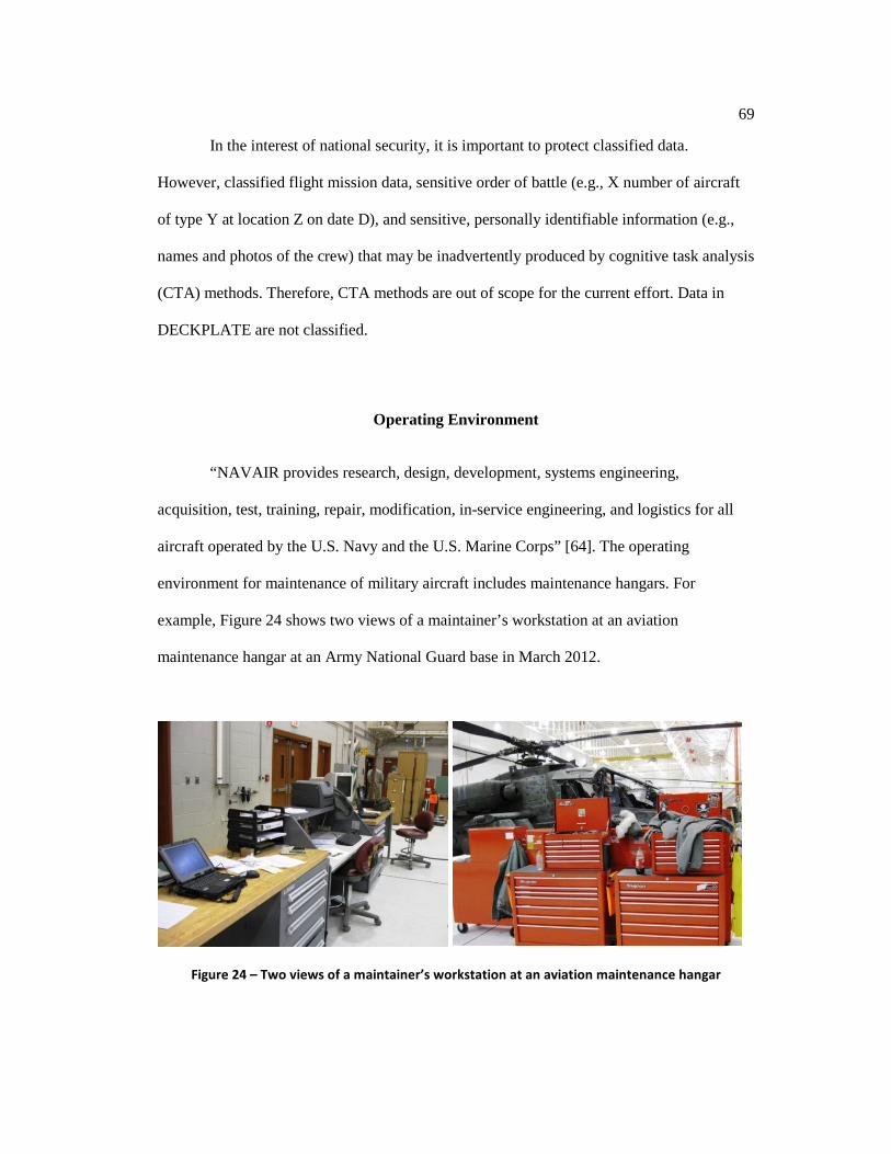
69
In the interest of national security, it is important to protect classified data.
However, classified flight mission data, sensitive order of battle (e.g., X number of aircraft
of type Y at location Z on date D), and sensitive, personally identifiable information (e.g.,
names and photos of the crew) that may be inadvertently produced by cognitive task analysis
(CTA) methods. Therefore, CTA methods are out of scope for the current effort. Data in
DECKPLATE are not classified.
Operating Environment
“NAVAIR provides research, design, development, systems engineering,
acquisition, test, training, repair, modification, in-service engineering, and logistics for all
aircraft operated by the U.S. Navy and the U.S. Marine Corps” [64]. The operating
environment for maintenance of military aircraft includes maintenance hangars. For
example, Figure 24 shows two views of a maintainer’s workstation at an aviation
maintenance hangar at an Army National Guard base in March 2012.
Figure 24 – Two views of a maintainer’s workstation at an aviation maintenance hangar

70
NAVAIR is responsible for U.S. Navy and U.S. Marine Corps rotorcraft, tiltrotor,
fixed-wing, and unmanned aircraft. The Tri-Service designation system uses an optional
one-character modified mission code, one-character basic mission code (see Table 10), a
one-character aircraft type code (not required for fixed-wing aircraft; see Table 11), a dash, a
numeric aircraft model, and a one-character aircraft series code [189]. Subsequent variants
of the same basic aircraft are given sequential series codes, starting with the letter A. For
example, MH-53E is the fifth variant (“E” is the fifth letter of the alphabet) of multi-mission
helicopter model 53. DON aircraft variants are referred to as a type/model/series (T/M/S).
Table 10 – Selected Tri-Service designation system aircraft mission codes4 Source: Covington [189]
Mission Code Mission A Attack C Cargo Transport E Electronic Countermeasures F Fighter H Search and Rescue K Tanker M Multi-Mission P Maritime Patrol R Reconnaissance S Antisubmarine T Trainer U Utility V Staff Transport X Experimental
Table 11 – Selected Tri-Service designation aircraft types5 Source: Covington [189]
Type Code Type H Helicopter Q Unmanned Aerial System (UAS) V VTOL
4 Boldface and underlining has been added for emphasis. 5 Tri-Service designation is not required for fixed-wing aircraft.

71
NAVAIR is responsible for thousands of Navy and Marine Corps aircraft, which are
comprised of the 64 aircraft variants.
Population
DECKPLATE contains approximately ten terabytes of maintenance data from
aviation squadrons on military bases, a natural setting for aviation operations, reflecting the
context of maintenance performed. DECKPLATE contains one record for every
maintenance action performed on the thousands of aircraft. Hundreds of millions of
maintenance action records are in DECKPLATE.
Out of the 64 aircraft variants, this dissertation focused on one: the MV-22B Osprey
(see example in Figure 25). Out of several thousand aircraft at NAVAIR, several hundred
are MV-22Bs, and the Marine Corps uses those aircraft extensively. In DECKPLATE, there
are approximately one million records of MV-22B data, one for every maintenance action
performed on MV-22B aircraft from July 1999 forward. This is the entire population, not
just a sample.
Access to DECKPLATE provided to the author by NAVAIR is a rare opportunity to
analyze aviation maintenance data for which access would otherwise be difficult or
impossible to obtain due to two reasons. First, caution by the information assurance (IA)
bureaucracy could delay or block a research project. Second, program manager (PM) or
OEM protectionism could block a research project due to worry about giving away
competitive advantage or about others discovering an embarrassing problem.

72
Figure 25 – An MV-22B Bell-Boeing Osprey Courtesy of the U.S. Marine Corps [70]
Data Set Development and Measures
In response to work orders written by pilot, copilot, crew chief, or maintenance
supervisor and additional face-to-face conversations, the data are entered by maintainers on
an electronic MAF in Naval Aviation Logistics Command Management Information System
(NALCOMIS), a DON information system [96]. As prescribed in the Naval Aviation
Maintenance Program (NAMP), maintainers fill out a MAF for every maintenance action
performed. Data from NALCOMIS are sent to DECKPLATE, which is the data set that was
utilized for the current dissertation.
Maintenance data in DECKPLATE contain faults, narratives, and aircraft
components chosen for action. Faults are represented by BIT codes, which are produced by
automatic diagnostic algorithms acting on measurements from electronic sensors. There is
no specific field in the data that solely conveys the fault. However, many diagnostic
maintenance actions give the fault either explicitly as a BIT code or describe the fault

73
textually in the descriptive and corrective action narratives. The narratives are the
observations of people, either pilots or maintainers.
Aircraft components repaired, replaced, fabricated, or calibrated during the
maintenance action are recorded by using a unified numbering system (UNS) code.
UNS is a system that provides a standardized methodology for functionally coding
equipment, systems, sub-systems, assemblies, components, and piece parts as they
apply to airborne weapons, trainers, and support equipment while providing a
specific designation reference for maintenance data collection [190].
Although there are hundreds of distinct BIT codes [183], 37 occur in the data set at
least 25 times. A sufficient number of occurrences is required to be useful in the
methodology described in the next chapter; therefore, only those that occurred at least 25
times were included. There are two narrative fields: the descriptive narrative and the
corrective action narrative. Each narrative consists of free-form text and is usually a
sentence or two in length. Although there are thousands of distinct UNS codes [190], 23 are
in the data set at least 40 times. Again, a sufficient number are required to be useful;
therefore, only the codes that occurred at least 40 times were included. Miscellaneous,
general, and “not otherwise classified” UNS codes were not used.
In addition to faults, narratives, and aircraft components chosen for repair,
replacement, fabrication, or calibration, several other fields of the data set are used. Type of
MAF code of troubleshooting (TYPE_MAF_CODE = TS) distinguished diagnostic
maintenance action for others. Completion date determines the year in which the
maintenance occurred, which is used for longitudinal analysis to show trends due to

74
expertise. Bureau number (BUNO6) identifies the specific aircraft, and is necessary in order
to determine success or failure of a diagnostic maintenance action by looking for recurrence
on the same aircraft over time. Man-hours are used to determine the diagnostic effort
performed, which is used to form levels for cross-sectional comparison.
Summary
The research problem at hand involved a combination of sensor data, human
observations, human decisions, and inferences. A retrospective design was chosen to
examine contextual influences on aviation maintainers’ decisions using an existing data set
because of the following reasons:
1. Retrospective design is a well-established method for observing subjects without
introducing interviewer bias [186][187]
2. Generalizable to the real-life context [188]
3. Does not suffer from reactive arrangements bias [188]
4. Economical (no travel costs were incurred in travelling from the author’s location in
State College, Pennsylvania, to NAVAIR headquarters in Patuxent River, Maryland)
5. Scheduling problems are avoided
6. Rare opportunity to analyze aviation maintenance data for which access would
otherwise be difficult to impossible to obtain due to the following:
a. Caution by the IA bureaucracy could delay or block a research project
b. PM and OEM protectionism could block a research project due to worry
about giving away competitive advantage
6 No BUNOs are divulged in this dissertation.

75
Chapter 6
Methodology
There is extensive literature on evaluation of the use of hard and soft data for
military situation assessment applications (e.g., a MURI project conducted recently at the
Pennsylvania State University College of Information Sciences and Technology [5]).
However, this application involved use of hard sensor data and human observations focused
on decision-making (e.g., related to aircraft maintenance). There has been no literature on
the application of hard and soft fusion techniques applied specifically to CBM+ of aircraft.
For this application, the soft data involves both observations of aircraft conditions and
contextual information that would modulate the interpretation of the hard sensor data.
Moreover, the hard and soft data are utilized for JDL level-3 processing (i.e., the
identification of potential hypotheses regarding impending mechanical failures and
evaluation of those hypotheses). Thus, it was necessary to formulate a research approach to
address this application.
In Chapter 1, research questions were identified to further our understanding of
hard/soft information fusion in the condition monitoring of aircraft. In this chapter, a
methodology is described and conducted to answer two research questions:
RQ1: Is there a significant association between the aircraft components selected
for action and the addition of human observations to sensor data in independent,
diagnostic maintenance actions on MV-22B aircraft?
76
RQ2: Is there a significant association between outcomes and the addition of
human observation to sensor data significantly associated in independent,
diagnostic maintenance actions on MV-22B aircraft?
RQ1 inquires about the association of sources of information and about its effect on
aircraft components chosen for repair, replacement, fabrication, or calibration, while RQ2
inquires about outcomes of maintenance actions.
A large data set from NAVAIR on maintenance of MV-22B aircraft provided the
opportunity to test each of these research questions. Research methodology, variables, and
development of hypotheses are outlined in this chapter, as well as relevant literature
supporting them.
Design and Tests
Xie et al. [191] and Davila et al. [192] built contingency tables and performed χ2
tests of association during their research on diagnosing cancer. Similarly, to best approach
the two main research questions, this study utilized 2xn and 2x2 contingency tables between
the explanatory variables of human observation and the response variables of aircraft
components chosen and outcome. Descriptive statistics were compiled about the variables,
and χ2 tests of association were performed on the contingency tables.
Limitations and Operational Definitions
For the purpose of this dissertation, complexity, content, and expertise are
operationally defined, and limitations of the data set are noted in this section. Complexity is

77
the difficulty involved in the cognitive processing of the many facets involved in diagnosing
a problem with the aircraft. There are many possible ways to operationally define
complexity. However, due to the limitations in the current data set, the best available
operational definition is by using diagnostic effort. Diagnostic maintenance actions were
divided at median diagnostic effort into two groups: noncomplex and complex. Problems
that require more effort to resolve are more complex because they have many different
facets to process and evaluate [193].
Content is subject matter of relevance. Specifically, faults and observations of
aircraft condition are considered content, and they that appear either numerically of textually
in the maintenance narratives. Content analysis on the narratives was coded as particular
faults or as a human observation using natural language processing.
Expertise is the level of skill or knowledge that a maintainer has in aviation
maintenance. However, a limitation of the current data set is that the identities of individual
maintainers were not available; therefore, it was not possible to categorize an individual
maintainer’s expertise (e.g., novice, journeyman, expert). Due to this limitation, only
longitudinal, descriptive statistics of overall diagnostic effort in man-hours could be
compiled. Expert maintainers would require less effort to diagnose a problem than would
novices.
Explanatory Variables
Human observations were coded based on a list of 1-, 2-, and 3-grams using content
analysis on the descriptive narrative and corrective narrative fields of diagnostic
maintenance records in the data set using commercially available text mining software
(RapidMiner). The descriptive narrative is a free-form text field entered by the maintainer,
78
which also contains gripes from the pilot that describes the perceived problem with the
aircraft. The corrective action narrative is another free-form text field that is entered by the
maintainer, which describes the corrective action performed on the aircraft.
N-grams with adjectives (e.g., “disbonded,” “visible”), references to periods (e.g.,
“on landing”), or references to persons (e.g., “pilot states”) were used to code the
explanatory variable for either presence (human observation = 1) or lack (human observation
= 0) of human observation. A full list of phrases coded as human observations is provided in
Appendix A. The list was cross-checked for accuracy and relevance by a SME in aviation
maintenance.
Problem complexity is a contextual variable. In complex problems, ambiguity
weakens the links between an aircraft’s true condition, the chosen diagnosis, and the action
performed. This ambiguity lengthens sense making and problem solving [194]; therefore,
diagnostic effort increases.
In order to test if problem complexity is a factor, the data set was divided into two
groups by complexity. Problem complexity was derived using the diagnostic effort in man-
hours. Because of the heavy skew to the right, the median7 is a better measure of central
tendency for this case (descriptive statistics are in Chapter 7). Diagnostic maintenance
actions with higher than median diagnostic effort were coded as complex (complex = 1), and
diagnostic maintenance actions with average or lower diagnostic effort were coded as
noncomplex (complex = 0).
Another factor is expertise. As maintainers gain expertise on the MV-22B, aircraft
components chosen and the outcome may differ from previous years. DECKPLATE
contains entries from July 1999 to September 2013. However, it does not record a
7 Note that for skewed distributions, the median tends to move closed to the mean as sample
size increases; therefore, as n increases, the median would decrease slightly, and more diagnostic maintenance actions would be classified as complex.
79
maintainer’s identity, so it is impossible to monitor an individual maintainer’s expertise over
time. However, it is plausible that on average, maintainers had lower expertise on the MV-
22B in the first few years than in later years. The effect of expertise as a confounding factor
was explored by examining longitudinal trends.
Response Variables
For RQ1, the response variable is the aircraft components chosen for repair,
replacement, fabrication, or calibration by maintainers of MV-22B aircraft. Aircraft
components are represented by UNS codes [190], which consist of up to 14 alphanumeric
characters that are defined by the U.S. Department of the Navy.
Aircraft components were grouped by fault during this study. There is no specific
field in the data that solely conveys the fault. However, many diagnostic maintenance
actions give the fault either in numerical form as a BIT code or by describing the fault
textually in the descriptive and corrective action narratives. Faults not written explicitly as
BIT codes were derived from the narrative fields. Using content analysis, faults and
corresponding BIT codes were derived. Additionally, a list of nonstandard words and
acronyms used in the descriptive narrative and corrective action narrative were compiled to
examine maintainers’ information-seeking behavior. Adjectives (e.g. “discolored”),
references to time periods (e.g., “on landing”), or references to person (e.g., “pilot states”)
would indicate that the maintainer sought information, including context-based assessments,
from colleagues.
For RQ2, the response variable is the outcome of diagnostic maintenance actions on
MV-22B aircraft. The outcome of the maintenance action performed is either successful or
unsuccessful. This dissertation defines an unsuccessful outcome as one in which the same

80
BIT code recurs during the subsequent 90 days. Conversely, in a successful outcome, the
same BIT code does not recur during the subsequent 90 days. Generally, MV-22B aircraft
fly twice per week, and it unlikely that an active aircraft would not fly during a 90-day
period.
Development of Hypotheses
The overall goal of this study is to understand the effect of hard/soft information
fusion on aviation maintenance. More specifically, it is to understand the addition of human
observation to sensor data on aircraft components chosen for repair, replacement,
fabrication, or calibration of independent diagnostic maintenance actions on MV-22B
aircraft, and, perhaps most importantly, on outcomes. Using the metrics described and the
research questions outlined at the beginning of this chapter, three hypotheses were
developed for this observational study. The following section describes the development of
each hypothesis.
Traditionally, CBM+ involves equipping machinery with electronic sensors to gather
data for diagnostic analysis. While these electronic sensors provide valuable data, they lack
human cognition, which excels at multisensory pattern recognition, natural language [149],
intuition [150], versatility, inductive reasoning, judgment [116], and decision-making. This
dissertation focuses on decision-making because of its key role in aviation maintenance.
Human strengths provide an opportunity to utilize a dynamic resource—people
acting as soft sensors. The fusion of human observation and sensor data creates a fuller
picture of machinery condition [140]. The key is humans making context-based assessments
of what the machine is doing (conditions under which it is operating, etc.) when the
observations are made [151]. Therefore, Hypothesis 1 (H1) follows:
81
H1: There is a significant association between the aircraft components selected for
action and the addition of human observations to sensor data in independent,
diagnostic maintenance actions on MV-22B aircraft.
Complexity is a contextual variable [195]. Humans have an innate advantage over
hard sensors with respect to context awareness that may influence outcomes [52]. Therefore,
Hypothesis 2 (H2) and Hypothesis 3 (H3) follow:
H2: For noncomplex problems, there is a significant association between outcomes
and the addition of human observation to sensor data in independent, diagnostic
maintenance actions on MV-22B aircraft.
H3: For complex problems, there is a significant association between outcomes
and the addition of human observation to sensor data in independent, diagnostic
maintenance actions on MV-22B aircraft.
Summary
A research approach was formulated to study hard/soft information fusion for the
condition monitoring of aircraft. Key hypotheses were identified, key variables and factors
were indicated, and the evaluation of hypotheses using statistical tests was explained.
82
Chapter 7
Summary of Results
This chapter presents a summary of the results of the evaluation of the three
hypotheses H1, H2, and H3. Data were analyzed from a NAVAIR database called
DECKPLATE, which included free-form text data about conditions and resulting decisions
about MV-22B aircraft maintenance actions. Statistical analyses were conducted that were
comprised of χ2 tests of association on contingency tables. H1 and H3 were statistically,
highly significant, while H2 was not statistically significant.
Hypothesis 1
H1 inquires about the effect of hard/soft fusion on actions chosen in diagnostic
maintenance. The variables are human observation and aircraft components chosen.
Descriptive statistics, test conditions, and significance tests are explained in this section.
Descriptive Statistics
Data in DECKPLATE contain approximately ten terabytes of maintenance data
from aviation squadrons on U.S. Navy and U.S. Marine Corps bases. Faults are represented
as BIT codes [183]. DECKPLATE contains one record for every maintenance action
performed on the aircraft, totaling hundreds of millions of maintenance action records.
Out of the 64 aircraft variants, this report focuses on one: the MV-22B Osprey. Out
of several thousand aircraft at NAVAIR, several hundred are MV-22Bs, and the Marine
Corps uses those aircraft extensively. In DECKPLATE, there are approximately 800,000
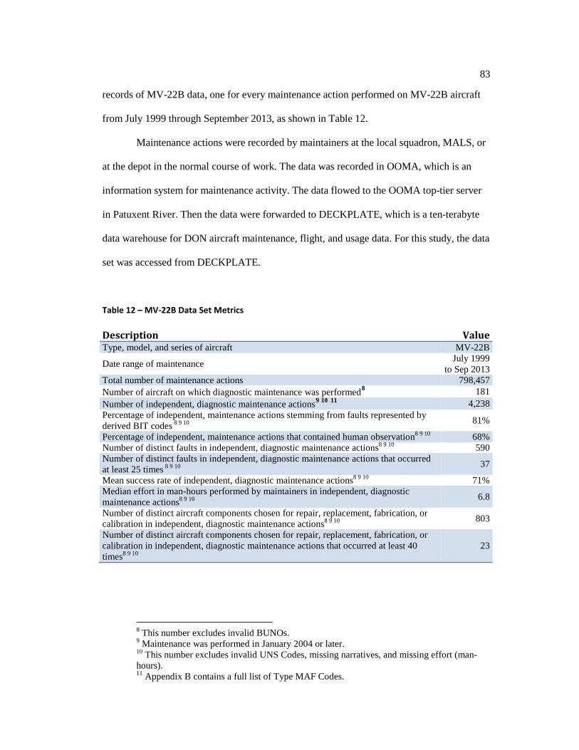
83
records of MV-22B data, one for every maintenance action performed on MV-22B aircraft
from July 1999 through September 2013, as shown in Table 12.
Maintenance actions were recorded by maintainers at the local squadron, MALS, or
at the depot in the normal course of work. The data was recorded in OOMA, which is an
information system for maintenance activity. The data flowed to the OOMA top-tier server
in Patuxent River. Then the data were forwarded to DECKPLATE, which is a ten-terabyte
data warehouse for DON aircraft maintenance, flight, and usage data. For this study, the data
set was accessed from DECKPLATE.
Table 12 – MV-22B Data Set Metrics
Description Value Type, model, and series of aircraft MV-22B
Date range of maintenance July 1999 to Sep 2013
Total number of maintenance actions 798,457 Number of aircraft on which diagnostic maintenance was performed8 181 Number of independent, diagnostic maintenance actions9 10 11 4,238 Percentage of independent, maintenance actions stemming from faults represented by derived BIT codes 8 9 10 81%
Percentage of independent, maintenance actions that contained human observation8 9 10 68% Number of distinct faults in independent, diagnostic maintenance actions8 9 10 590 Number of distinct faults in independent, diagnostic maintenance actions that occurred at least 25 times 8 9 10 37
Mean success rate of independent, diagnostic maintenance actions8 9 10 71% Median effort in man-hours performed by maintainers in independent, diagnostic maintenance actions8 9 10 6.8
Number of distinct aircraft components chosen for repair, replacement, fabrication, or calibration in independent, diagnostic maintenance actions8 9 10 803
Number of distinct aircraft components chosen for repair, replacement, fabrication, or calibration in independent, diagnostic maintenance actions that occurred at least 40 times8 9 10
23
8 This number excludes invalid BUNOs. 9 Maintenance was performed in January 2004 or later. 10 This number excludes invalid UNS Codes, missing narratives, and missing effort (man-hours). 11 Appendix B contains a full list of Type MAF Codes.

84
Every record of the data set represents a maintenance action. The data set contained
798,457 maintenance actions in total. Maintenance actions with the same Job Control
Number (JCN) are related. A requirement of the χ2 test applied in this study is to have
independent samples. Therefore, this analysis excludes more than one diagnostic
maintenance actions with the same JCN. This was done by identifying, by date, the first
completed diagnostic maintenance action of each JCN, and then excluding the remaining
maintenance actions. This study is about diagnostics, so it only includes diagnostic
maintenance actions (TYPE_MAF_CODE = TS), not of related repairs, replacements,
inspections, etc.
As shown in Figure 26, very few maintenance actions were performed before 2004.
This is because very few MV-22B aircraft were manufactured and operational before 2004.
Therefore, for better statistical power, records prior to 2004 are excluded from further
analysis. From 2004, the number of maintenance actions generally increased yearly as
additional aircraft became operational. The last year, 2013, only covers the first three
quarters; therefore, it shows fewer maintenance actions.
20132012201120102009200820072006200520042003200220012000
900
800
700
600
500
400
300
200
100
0
Year
Freq
uenc
y
Independent, Diagnostic Maintenance Actionsby Year
Figure 26 – Histogram of the number of independent, diagnostic maintenance actions by year
85
Maintenance actions containing invalid BUNOs (e.g., 012345, 111111, 222222),
undetermined UNS codes (76AFJ00, 71X2Z, 4511800, 1000000, 71X2800, 44000, 45000,
4500000, and 25504103), missing narratives, or missing effort (i.e., man-hours) were
excluded. After all of the exclusions, 4,238 maintenance records that met all of the criteria
remained.
Sensor data are used by the built-in test equipment of the aircraft to estimate faults
(e.g., “FCS - L OUTBD SWASHPLATE ACTUATOR (FCC 1)”) represented by BIT codes
(e.g., 4680), which are Navy-defined [183], four-character hexadecimal codes. The response
variable was grouped by fault. There is no specific field in the data that solely conveys the
fault. However, many diagnostic maintenance actions give the fault either in numerical form
as a BIT code or by describing the fault textually in the descriptive and corrective action
narratives.
Faults that are not written explicitly as BIT codes were derived from the narrative
fields. Using content analysis, a list of nonstandard words and acronyms used in the
descriptive narrative and corrective action narrative was compiled and used in the content
analysis for deriving the BIT codes of faults. In Chapter 8, inferences were made about the
cognitive processes underlying the decision-making during diagnostic maintenance. For a
complete list of nonstandard words (e.g., “LDG” means landing gear, “PNL” means panel)
used in the descriptive and corrective action narratives, see Appendix C. There were 3,452
independent maintenance actions stemming from derived BIT codes.
The outcome of a diagnostic maintenance action is either successful or unsuccessful.
This dissertation defines an unsuccessful outcome (outcome = 0) as one in which the same
fault recurs on the same aircraft during the subsequent 90 days. Conversely, in a successful

86
outcome (outcome = 1), the same fault does not recur during the subsequent 90 days. The
success rate, grouped by fault, is given in Eq. ( 1 ).
𝑠𝑠𝑠𝑠𝑠𝑠𝑠 𝑟𝑟𝑟𝑠 = 𝑛𝑠𝑛𝑛𝑠𝑟 𝑜𝑜 𝑠𝑠𝑠𝑠𝑠𝑠𝑠𝑜𝑠𝑠 𝑜𝑠𝑟𝑠𝑜𝑛𝑠𝑠
𝑛𝑠𝑛𝑛𝑠𝑟 𝑜𝑜 𝑠𝑠𝑠𝑠𝑠𝑠𝑠𝑜𝑠𝑠 𝑜𝑠𝑟𝑠𝑜𝑛𝑠𝑠 + 𝑛𝑠𝑛𝑛𝑠𝑟 𝑜𝑜 𝑠𝑛𝑠𝑠𝑠𝑠𝑠𝑠𝑠𝑜𝑠𝑠 𝑜𝑠𝑟𝑠𝑜𝑛𝑠𝑠 ( 1 )
Of the 590 distinct faults from independent, diagnostic maintenance actions, 37
distinct faults occurred at least 25 times; they are listed in Table 13. The number 25 was
used as a minimum for the reasons described in Chapter 5. Diagnostic maintenance actions
in response to “Rotor Brake - CALIPER POSITION SENSOR 1 (WIU)” had the best
success rate, at 0.93, and diagnostic maintenance actions in response to “Drive Train - CHIP
DETECTOR FAIL” had the worst success rate, at 0.43. At 17.35 man-hours, diagnostic
maintenance actions in response to “FCS - R INBD SWASHPLATE ACTUATOR (FCC 3)”
had the greatest mean diagnostic effort, and at 3.25 man-hours, diagnostic maintenance
actions in response to “Engine - R ABCV FADEC A” had the least mean diagnostic effort.
Table 13 – Distinct faults from independent, diagnostic maintenance actions that occurred at least 25 times BIT codes provided by the U.S. Navy [183]
Fault (BIT
Code)
Fault Description Success Rate
Mean Diagnostic Effort(man-hours)
2A00 NIU - R NIU FAIL 0.80 10.20 430E APU - APU FAIL TO LIGHT 0.58 7.85 4680 FCS - L OUTBD SWASHPLATE ACTUATOR (FCC 1) 0.69 9.90 4683 FCS - R OUTBD SWASHPLATE ACTUATOR (FCC 1) 0.85 13.97 4684 FCS - R CNTR SWASHPLATE ACTUATOR (FCC 1) 0.81 12.58 4685 FCS - R INBD SWASHPLATE ACTUATOR (FCC 1) 0.76 12.39 4687 L INBD OUTBD FLAPERON ACTR 0.76 10.34 46BE FCS - L HPDU 1 0.74 11.84 4884 FCS - R CNTR SWASHPLATE ACTUATOR (FCC 2) 0.64 10.73
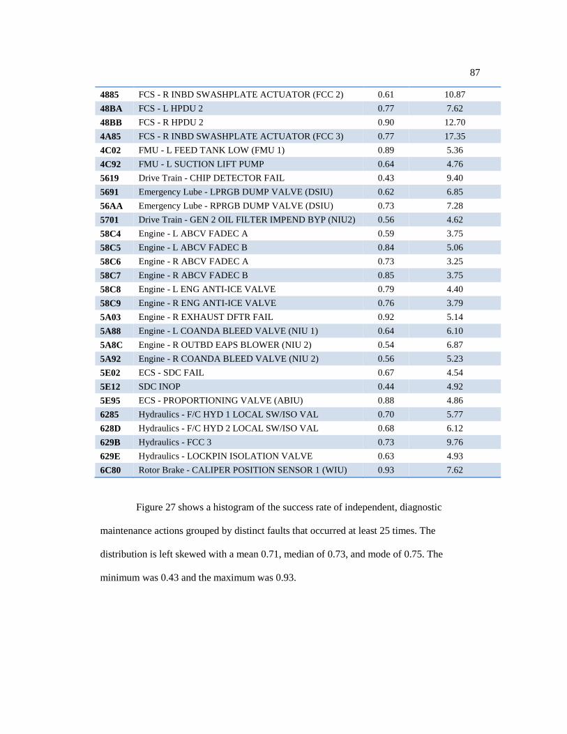
87
4885 FCS - R INBD SWASHPLATE ACTUATOR (FCC 2) 0.61 10.87 48BA FCS - L HPDU 2 0.77 7.62 48BB FCS - R HPDU 2 0.90 12.70 4A85 FCS - R INBD SWASHPLATE ACTUATOR (FCC 3) 0.77 17.35 4C02 FMU - L FEED TANK LOW (FMU 1) 0.89 5.36 4C92 FMU - L SUCTION LIFT PUMP 0.64 4.76 5619 Drive Train - CHIP DETECTOR FAIL 0.43 9.40 5691 Emergency Lube - LPRGB DUMP VALVE (DSIU) 0.62 6.85 56AA Emergency Lube - RPRGB DUMP VALVE (DSIU) 0.73 7.28 5701 Drive Train - GEN 2 OIL FILTER IMPEND BYP (NIU2) 0.56 4.62 58C4 Engine - L ABCV FADEC A 0.59 3.75 58C5 Engine - L ABCV FADEC B 0.84 5.06 58C6 Engine - R ABCV FADEC A 0.73 3.25 58C7 Engine - R ABCV FADEC B 0.85 3.75 58C8 Engine - L ENG ANTI-ICE VALVE 0.79 4.40 58C9 Engine - R ENG ANTI-ICE VALVE 0.76 3.79 5A03 Engine - R EXHAUST DFTR FAIL 0.92 5.14 5A88 Engine - L COANDA BLEED VALVE (NIU 1) 0.64 6.10 5A8C Engine - R OUTBD EAPS BLOWER (NIU 2) 0.54 6.87 5A92 Engine - R COANDA BLEED VALVE (NIU 2) 0.56 5.23 5E02 ECS - SDC FAIL 0.67 4.54 5E12 SDC INOP 0.44 4.92 5E95 ECS - PROPORTIONING VALVE (ABIU) 0.88 4.86 6285 Hydraulics - F/C HYD 1 LOCAL SW/ISO VAL 0.70 5.77 628D Hydraulics - F/C HYD 2 LOCAL SW/ISO VAL 0.68 6.12 629B Hydraulics - FCC 3 0.73 9.76 629E Hydraulics - LOCKPIN ISOLATION VALVE 0.63 4.93 6C80 Rotor Brake - CALIPER POSITION SENSOR 1 (WIU) 0.93 7.62
Figure 27 shows a histogram of the success rate of independent, diagnostic
maintenance actions grouped by distinct faults that occurred at least 25 times. The
distribution is left skewed with a mean 0.71, median of 0.73, and mode of 0.75. The
minimum was 0.43 and the maximum was 0.93.
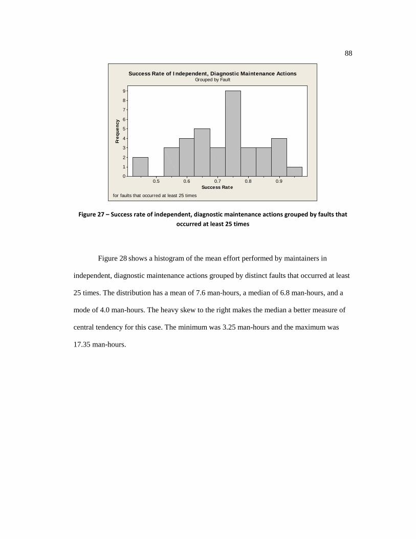
88
0.90.80.70.60.5
9
8
7
6
5
4
3
2
1
0
Success Rate
Freq
uenc
y
Success Rate of Independent, Diagnostic Maintenance ActionsGrouped by Fault
for faults that occurred at least 25 times
Figure 27 – Success rate of independent, diagnostic maintenance actions grouped by faults that occurred at least 25 times
Figure 28 shows a histogram of the mean effort performed by maintainers in
independent, diagnostic maintenance actions grouped by distinct faults that occurred at least
25 times. The distribution has a mean of 7.6 man-hours, a median of 6.8 man-hours, and a
mode of 4.0 man-hours. The heavy skew to the right makes the median a better measure of
central tendency for this case. The minimum was 3.25 man-hours and the maximum was
17.35 man-hours.

89
1816141210864
12
10
8
6
4
2
0
Man-Hours
Freq
uenc
y
Mean Effort Performed by Mantainersin Independent, Diagnostic Maintenance Actions, Grouped by Fault
for faults that occurred at least 25 times Figure 28 – Mean effort of maintainers in independent, diagnostic maintenance actions grouped
by faults that occurred at least 25 times
Of the 803 distinct aircraft components chosen for repair, replacement, fabrication,
or calibration in independent, diagnostic maintenance actions, 23 distinct faults occurred at
least 40 times. They are listed in Table 14. A minimum of 40 was chosen to ensure that no
more than 20% of the cells in the forthcoming contingency table had expected counts of less
than 5 in a χ2 test. The most frequent aircraft component chosen for repair, replacement,
fabrication, or calibration in independent, diagnostic maintenance actions was a “LEFT
ANTI-ICING AIR VALVE,” which is a safety-critical part of the anti-icing system. During
icing conditions (e.g., freezing rain), the MV-22B can direct hot air, called bleed air, from
the engines to prevent ice from accreting on the wing, proprotors, and empennage.
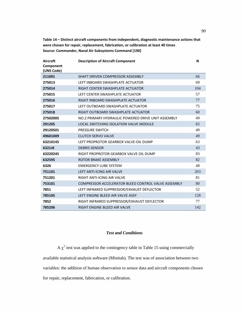
90
Table 14 – Distinct aircraft components from independent, diagnostic maintenance actions that were chosen for repair, replacement, fabrication, or calibration at least 40 times Source: Commander, Naval Air Subsystems Command [190]
Aircraft Component (UNS Code)
Description of Aircraft Component N
211001 SHAFT DRIVEN COMPRESSOR ASSEMBLY 66 275013 LEFT INBOARD SWASHPLATE ACTUATOR 69 275014 RIGHT CENTER SWASHPLATE ACTUATOR 104 275015 LEFT CENTER SWASHPLATE ACTUATOR 57 275016 RIGHT INBOARD SWASHPLATE ACTUATOR 77 275017 LEFT OUTBOARD SWASHPLATE ACTUATOR 75 275018 RIGHT OUTBOARD SWASHPLATE ACTUATOR 60 27502005 NO.2 PRIMARY HYDRAULIC POWERED DRIVE UNIT ASSEMBLY 49 291205 LOCAL SWITCHING ISOLATION VALVE MODULE 65 29120501 PRESSURE SWITCH 49 49601009 CLUTCH SERVO VALVE 49 63210145 LEFT PROPROTOR GEARBOX VALVE-OIL DUMP 63 6321JK DEBRIS SENSOR 43 63220245 RIGHT PROPROTOR GEARBOX VALVE OIL DUMP 83 632595 ROTOR BRAKE ASSEMBLY 82 6326 EMERGENCY LUBE SYSTEM 48 751101 LEFT ANTI-ICING AIR VALVE 203 751201 RIGHT ANTI-ICING AIR VALVE 81 753101 COMPRESSOR ACCELERATOR BLEED CONTROL VALVE ASSEMBLY 80 7851 LEFT INFRARED SUPPRESSOR/EXHAUST DEFLECTOR 52 785105 LEFT ENGINE BLEED AIR VALVE ASSY 128 7852 RIGHT INFRARED SUPPRESSOR/EXHAUST DEFLECTOR 77 785206 RIGHT ENGINE BLEED AIR VALVE 142
Test and Conditions
A χ2 test was applied to the contingency table in Table 15 using commercially
available statistical analysis software (Minitab). The test was of association between two
variables: the addition of human observation to sensor data and aircraft components chosen
for repair, replacement, fabrication, or calibration.
91
The χ2 test measures the divergence of observed data from expected values under
H10. The expected value of each cell was calculated in accordance with Eq. (2), where n is
the total number of observations included in the table.
(row total*column total)/n ( 2 )
The following are conditions for a χ2 test of association: independence, having no
cells in the contingency table with expected counts of less than 1, and having no more than
20% of the cells in the contingency table with expected counts of less than 5. In Table 15,
the contingency table of human observation and aircraft components chosen for repair,
replacement, fabrication, or calibration was compiled from diagnostic maintenance actions
of different JCNs; therefore, observations were independent, meeting the first condition. The
expected counts (not shown) meet the second and third conditions of the χ2 test.

92
Table 15 – The contingency table of human observation and aircraft components
Count Human Observation No Yes Total UNS 211001 14 52 66 275013 14 55 69 275014 27 77 104 275015 8 49 57 275016 26 51 77 275017 23 52 75 275018 17 43 60 27502005 24 25 49 291205 24 41 65 29120501 18 31 49 49601009 22 27 49 63210145 14 49 63 6321JK 14 29 43 63220245 21 62 83 632595 26 56 82 6326 18 30 48 751101 49 154 203 751201 14 67 81 753101 32 48 80 7851 15 37 52 785105 29 99 128 7852 19 58 77 785206 26 116 142 Total 494 1308 1802
Table 16 – χ2 tests for H1
Value Df p Pearson χ2 58.512 22 0.000 Likelihood Ratio χ2 57.532 22 0.000
Test of Significance
In Table 16, the Pearson χ2 test for association between human observation and
aircraft components had a very small p-value of approximately zero and a very large
magnitude test statistic of 58.512. The degrees of freedom were 22. The likelihood ratio χ2
test also had a very small p-value of approximately zero and a very large magnitude test
statistic of 57.532. Because the p-value is less than α = 0.05, H10, is rejected, and the

93
association is statistically, highly significant between the addition of human observation to
sensor data and aircraft components chosen for repair, replacement, fabrication, or
calibration.
Hypotheses 2 and 3
H2 and H3 inquire about hard/soft fusion and its effect on outcomes of diagnostic
maintenance. The variables are human observation, complexity, and outcomes. Descriptive
statistics, test conditions, and significance tests are explained in this section.
Descriptive Statistics
In Figure 29, human observation is plotted vs. mean success rate of independent,
diagnostic maintenance actions. The dashed red line shows the relationship between human
observation and mean success rate for complex problems, and the solid black line shows the
relationship for noncomplex problems. Mean success rates were computed across faults in a
two-by-two cross section: no human observation, noncomplex; no human observation,
complex; human observation, noncomplex; and human observation, complex. The two lines
are not parallel, so there is an interaction with problem complexity. For complex problems,
there is a strong, positive relationship between human observation and success rate. In
contrast, for noncomplex problems, there is a slight, positive relationship.

94
10
0.78
0.77
0.76
0.75
0.74
0.73
0.72
0.71
0.70
0.69
Human Observation (1 = Yes, 0 = No)
Mea
n Su
cces
s R
ate
01
Complexity
Success Rate of Diagnosticsby Human Observation and Problem Complexity
Figure 29 – Human observation vs. mean success rate of independent, diagnostic maintenance actions by complexity
In the relationships between human observation and mean diagnostic effort, grouped
by fault (see Figure 30), the dashed red line shows the relationship between human
observation and diagnostic effort for complex problems, and the solid black line shows the
relationship for noncomplex problems. Mean diagnostic effort was computed across faults in
the same two-by-two cross section: no human observation, noncomplex; no human
observation, complex; human observation, noncomplex; and human observation, complex.
There is an interaction with problem complexity, as evidenced by the fact that the two lines
are not parallel. For complex problems, there is a negative relationship between human
observation and diagnostic effort. In contrast, for noncomplex problems, there is almost no
relationship.

95
10
20
15
10
5
Human Observation (1 = Yes, 0 = No)
Mea
n D
iagn
osti
c Ef
fort
(m
an-h
ours
) 01
Complexity
Diagnostic Effortby Human Observation and Problem Complexity
Figure 30 – Human observation vs. mean diagnostic effort, grouped by fault, of independent, diagnostic maintenance actions by complexity
In research on medical diagnostics, expertise was found to be a factor associated
with patient outcomes [196]. Likewise, expertise could be factor in aircraft maintenance. As
Hobbs said, “From a human factors perspective, maintenance personnel have more in
common with doctors than with pilots” [44].
Although DECKPLATE does not record the maintainers’ identities, making it
impossible to monitor an individual maintainer’s proficiency over time, a longitudinal look
at mean diagnostic effort may offer some insight. Figure 31 is a plot of mean diagnostic
effort vs. year. Maintenance actions before 2004 were excluded, because very few MV-22B
aircraft were in operation at that time. The dashed red line shows mean diagnostic effort for
complex problems of independent, diagnostic maintenance actions, grouped by fault that
included human observation of the aircraft condition. The solid black line shows effort vs.
year for the same maintenance actions, grouped by fault, but without human observation of
the aircraft condition.
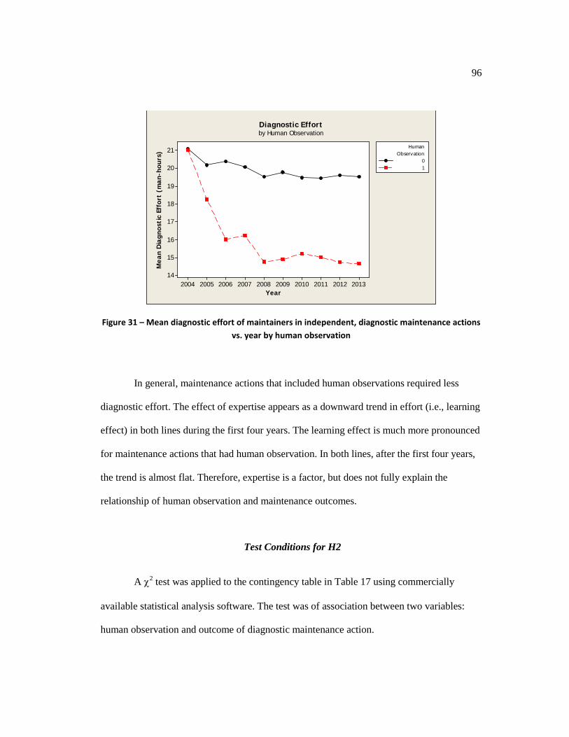
96
2013201220112010200920082007200620052004
21
20
19
18
17
16
15
14
Year
Mea
n D
iagn
osti
c Ef
fort
(m
an-h
ours
)01
ObservationHuman
Diagnostic Effortby Human Observation
Figure 31 – Mean diagnostic effort of maintainers in independent, diagnostic maintenance actions vs. year by human observation
In general, maintenance actions that included human observations required less
diagnostic effort. The effect of expertise appears as a downward trend in effort (i.e., learning
effect) in both lines during the first four years. The learning effect is much more pronounced
for maintenance actions that had human observation. In both lines, after the first four years,
the trend is almost flat. Therefore, expertise is a factor, but does not fully explain the
relationship of human observation and maintenance outcomes.
Test Conditions for H2
A χ2 test was applied to the contingency table in Table 17 using commercially
available statistical analysis software. The test was of association between two variables:
human observation and outcome of diagnostic maintenance action.
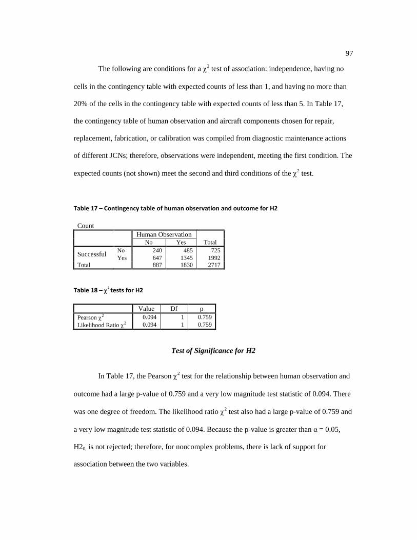
97
The following are conditions for a χ2 test of association: independence, having no
cells in the contingency table with expected counts of less than 1, and having no more than
20% of the cells in the contingency table with expected counts of less than 5. In Table 17,
the contingency table of human observation and aircraft components chosen for repair,
replacement, fabrication, or calibration was compiled from diagnostic maintenance actions
of different JCNs; therefore, observations were independent, meeting the first condition. The
expected counts (not shown) meet the second and third conditions of the χ2 test.
Table 17 – Contingency table of human observation and outcome for H2
Count Human Observation No Yes Total
Successful No 240 485 725 Yes 647 1345 1992
Total 887 1830 2717 Table 18 – χ2 tests for H2
Value Df p Pearson χ2 0.094 1 0.759 Likelihood Ratio χ2 0.094 1 0.759
Test of Significance for H2
In Table 17, the Pearson χ2 test for the relationship between human observation and
outcome had a large p-value of 0.759 and a very low magnitude test statistic of 0.094. There
was one degree of freedom. The likelihood ratio χ2 test also had a large p-value of 0.759 and
a very low magnitude test statistic of 0.094. Because the p-value is greater than α = 0.05,
H20, is not rejected; therefore, for noncomplex problems, there is lack of support for
association between the two variables.

98
Test Conditions for H3
A χ2 test of association was applied between two variables: human observation and
outcome of diagnostic maintenance action. In Table 19, the contingency table of human
observation and aircraft components chosen for repair, replacement, fabrication, or
calibration was compiled from diagnostic maintenance actions of different JCNs; therefore,
observations were independent, meeting the first condition of the χ2 test. The expected
counts (not shown) meet the second and third conditions of the test.
Table 19 – Contingency table of human observation and outcome for H3
Count Human Observation No Yes Total
Successful No 145 231 376 Yes 335 810 1145
Total 480 1041 1521 Table 20 – χ2 tests for H3
Value Df p Pearson χ2 11.349 1 0.001 Likelihood Ratio χ2 11.095 1 0.001
Test of Significance for H3
In Table 20, the Pearson χ2 test for the relationship between human observation and
outcome had a very small p-value of 0.001 and a large magnitude test statistic of 11.349.
There was one degree of freedom. The likelihood ratio χ2 test also had a very low p-value of
0.001 and a large magnitude test statistic of 11.095. Because the p-value is less than α =
0.05. Therefore, for complex problems, H30, is rejected, and there is a statistically highly

99
significant, positive relationship between human observation and outcome of independent
diagnostic maintenance actions on MV-22B aircraft.

100
Chapter 8
Discussion
Carroll and Johnson said, “Decision-making is a process by which a person …
identifies a choice to be made, gathers and evaluates information about alternatives, and
selects from among alternatives” [197]. Decision makers often gather information from
people. Researchers from a myriad of medical environments, including nursing [198][195],
physician practice [194], clinical decision-making [199], and audiology [200], have studied
medical professionals’ information-seeking behaviors to make inferences about the cognitive
processes underlying their decision-making and its implications for diagnoses, treatments,
and resulting outcomes.
In nursing, Bucknall found that the nurses’ decision-making was strongly influenced
by contextual variables, such as time, risk, and resource availability [198]. Carnevali and
Thomas demonstrated that task complexity is a factor in the number of cues that nurses
found accessible [195]. In physician practice, Eddy argued that ambiguity about a patient’s
symptoms weakens the links between a patient’s true condition and the chosen diagnosis and
treatment [194]. Dee and Blazek [196] found that physicians seek input from colleagues
because they convey relevant, context-aware information [201]. The impact of these
contextual variables on decision-making has implications for improving patient outcomes.
The researchers listed above devised the methodology to study health professionals’
information-seeking behavior and to make inferences about the cognitive processes
underlying their decision-making. A similar research design methodology is valid for
studying aviation maintenance, because, as Hobbs said, “From a human factors perspective,
maintenance personnel have more in common with doctors than with pilots” [44].
101
Maintainers of MV-22B aircraft often juggle competing priorities of safety against
the organizational unit’s mission readiness goals when selecting a decision-making strategy
(e.g., completing a landing gear inspection during the middle of the night before the
aircraft’s already scheduled dawn mission). Observing the information-seeking behavior of
maintainers of MV-22B aircraft, one can make inferences about the cognitive processes
underlying their decision-making and its implications for actions performed and resulting
outcomes.
Aviation maintainers’ information-seeking behaviors were examined in order to
study the cognitive processes underlying their decision-making during diagnostic
maintenance. Faults triggered by noncomplex problems frequently involve an obvious
diagnosis and action performed. Complex problems frequently require a second decision-
making strategy: weighing multiple options, which involves the adaptability and context
sensitivity of people as observers. Complex problems on MV-22B aircraft evidenced a
strong negative relationship between human observation and diagnostic effort; in contrast,
noncomplex problems evidenced a weak relationship. Therefore, human input most
benefitted the diagnosis of complex problems in MV-22B aircraft.
Complexity is a contextual factor. Reduced diagnostic effort indicated that human
observations decreased the ambiguity of the problem by providing context awareness.
Higher success rates corresponded with human observations. The innate context awareness
of pilot, crew chief, and maintainer strengthened the links between an aircraft’s true
condition and aircraft components chosen for repair, replacement, fabrication, or calibration.
Rationality is a style of behavior in which cost and benefit (a.k.a. utility) are
weighed toward the achievement of a goal. The theory of bounded rationality incorporates
the influence of the field environment (i.e., context) on cognitive processes related to
information seeking and use [202]. According to Simon, decision makers exhibit two
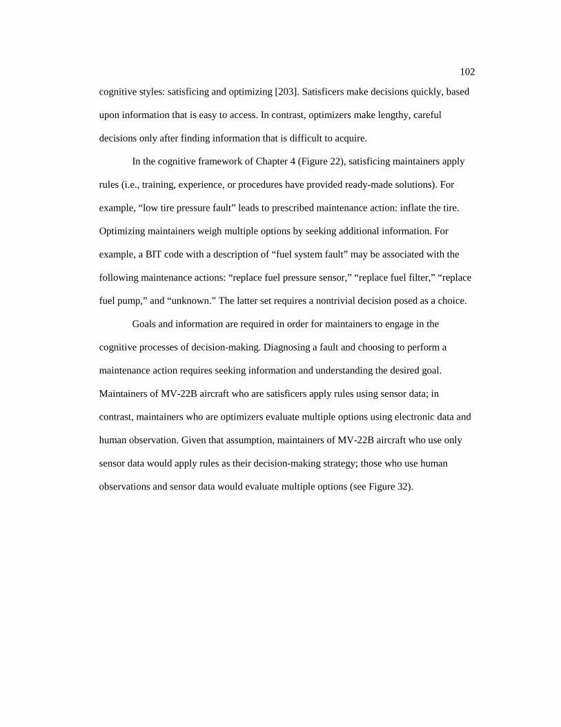
102
cognitive styles: satisficing and optimizing [203]. Satisficers make decisions quickly, based
upon information that is easy to access. In contrast, optimizers make lengthy, careful
decisions only after finding information that is difficult to acquire.
In the cognitive framework of Chapter 4 (Figure 22), satisficing maintainers apply
rules (i.e., training, experience, or procedures have provided ready-made solutions). For
example, “low tire pressure fault” leads to prescribed maintenance action: inflate the tire.
Optimizing maintainers weigh multiple options by seeking additional information. For
example, a BIT code with a description of “fuel system fault” may be associated with the
following maintenance actions: “replace fuel pressure sensor,” “replace fuel filter,” “replace
fuel pump,” and “unknown.” The latter set requires a nontrivial decision posed as a choice.
Goals and information are required in order for maintainers to engage in the
cognitive processes of decision-making. Diagnosing a fault and choosing to perform a
maintenance action requires seeking information and understanding the desired goal.
Maintainers of MV-22B aircraft who are satisficers apply rules using sensor data; in
contrast, maintainers who are optimizers evaluate multiple options using electronic data and
human observation. Given that assumption, maintainers of MV-22B aircraft who use only
sensor data would apply rules as their decision-making strategy; those who use human
observations and sensor data would evaluate multiple options (see Figure 32).
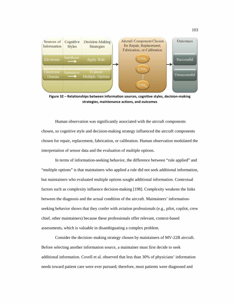
103
Figure 32 – Relationships between information sources, cognitive styles, decision-making
strategies, maintenance actions, and outcomes
Human observation was significantly associated with the aircraft components
chosen, so cognitive style and decision-making strategy influenced the aircraft components
chosen for repair, replacement, fabrication, or calibration. Human observation modulated the
interpretation of sensor data and the evaluation of multiple options.
In terms of information-seeking behavior, the difference between “rule applied” and
“multiple options” is that maintainers who applied a rule did not seek additional information,
but maintainers who evaluated multiple options sought additional information. Contextual
factors such as complexity influence decision-making [198]. Complexity weakens the links
between the diagnosis and the actual condition of the aircraft. Maintainers’ information-
seeking behavior shows that they confer with aviation professionals (e.g., pilot, copilot, crew
chief, other maintainers) because these professionals offer relevant, context-based
assessments, which is valuable in disambiguating a complex problem.
Consider the decision–making strategy chosen by maintainers of MV-22B aircraft.
Before selecting another information source, a maintainer must first decide to seek
additional information. Covell et al. observed that less than 30% of physicians’ information
needs toward patient care were ever pursued; therefore, most patients were diagnosed and

104
treated without additional information seeking [204]. Gorman and Helfand demonstrated
that the urgency of the problem and the belief in a definitive answer were positive predictors
of physicians seeking additional information [205].
Complex problems require a nontrivial decision by the maintainer. This dissertation
showed an association between human observation and aircraft components chosen for
repair, replacement, fabrication, or calibration. This dissertation also showed an association
between human observation and outcomes for complex problems. This is because
complexity led maintainers to adopt the cognitive style of optimizers and evaluate multiple
options in the cognitive framework of Chapter 4 (Figure 22). Human observation improved
outcomes and decreased diagnostic effort for complex problems. Maintainers’ decision-
making benefitted from context awareness [52] and adaptability [21].
Expertise was a factor, as evidenced by the learning effect of the first four years of
full-rate production. Level of expertise (e.g., novice, expert) is a factor in the cognitive
function and processes of the cognitive framework of Chapter 4 (Figure 22). For example,
the paucity of experiences and mental models of the novice results in less problem
recognition and more frequent “deepening” that requires more effort than for the expert.
A recent report for NAVAIR by the author [206] contains a ranked list of BIT codes
(i.e., faults) and UNS codes (i.e., aircraft components) repaired, replaced, fabricated, or
calibrated in the historical maintenance data of MV-22B. The purpose of that report was to
furnish MV-22B maintainers who are troubleshooting a fault with a ranked list of aircraft
components historically chosen for the particular fault code. In light of the current
dissertation, this ranked list is appropriate for noncomplex problems. However, for complex
problems, more is needed—human observation, including contextual information.

105
Suggestions for Further Research
The current research has inherent limitations, because it was retrospective. One
important limitation is the lack of knowledge about the individual maintainers and of insight
into the maintenance personnel’s cognitive processes and mental models due to the inability
to interview them and to ask about their information-seeking behaviors and decision-making
processes from their own perspective. Furthermore, retrospective studies such as this one do
not establish causality.
Future studies should address these limitations by conducting interviews with
maintainers. Interviews, based on CTA methods, would elicit knowledge needed to develop
mental models of the maintainers’ decision-making. The opportunity to gather information
about the training and experience of the maintainers would provide a way to control for the
confounding of expertise on the success rate of maintenance actions. Causality could be
established through the performance of planned experiments with aviation maintainers.
Another issue that could be explored by CTA methods is the definition of
complexity. Because of limitations in the data set, complexity was defined with respect to
median diagnostic effort. However, a broader view of complexity includes perception.
Novices would perceive more problems as complex than experts. Therefore, the frequencies
with which particular paths are taken in of the cognitive framework in Figure 22 may differ
between novices and experts. Knowledge of individual maintainer’s overall experience in
aviation maintenance, and years of experience in relevant T/M/S would enable a comparison
of how novices differ from experts in frequencies of paths taken of the cognitive framework.
Data on 63 other aircraft variants stored within DECKPLATE also could be
analyzed using the research approach developed in this dissertation. Additionally, the
106
research approach could be utilized to study hard/soft fusion in other domains where human
observations could be added to diagnostic procedures (e.g., medicine, auto mechanics).
Machines tend to be context insensitive [12] and need people to inform them of
changing context [52]. In this study, the context sensitivity of people as observers informed
the fusion process at higher levels of the JDL data fusion process model [139][140][136],
and this led to better outcomes. One application of this result is to enhance IETMs, so that
diagnostics procedures encourage the collection of relevant human observation, which may
provide substantial time and resource savings.
Additionally, IETMS could be enhanced using collaborative filtering (CF), which is
a set of data fusion techniques [207] utilized by many recommender systems (e.g., Tapestry
[208], GroupLens [209])12. Perhaps best known as “Customers Also Bought,” CF has been
used successfully by large online retailers (e.g., Amazon) as a way to enhance customers’
online shopping experience. Essentially, CF is the process of recognizing patterns of
information from multiple sources [211]. CF techniques typically operate over large data
sets.
CF techniques could be successfully applied to the domain of aviation maintenance.
For example, k-means clustering could be utilized to identify the k most similar diagnostic
maintenance actions for a set of human observations and BIT codes on a particular aircraft
variant. The resulting ranked list of the aircraft components could be titled “Maintainers
Also Chose.”
Furthermore, maintainers’ information-seeking behavior could be guided toward
statistically better outcomes during the diagnostic process by enhanced IETMS that analyze
historical maintenance actions for the relevant aircraft variant. For example, “80% of the
time, a better outcome occurred if the pilot were asked this additional question: …”
12 For a comprehensive list of CF techniques, see Su and Khoshgoftaar [210].

107
Chapter 9
Conclusions
The synergistic integration of information from electronic sensors and human
sources is called hard/soft information fusion. In the condition monitoring of aircraft, the
addition of the multisensory capability of human cognition to traditional condition
monitoring creates a more complete picture of aircraft condition. A large data set from
NAVAIR on maintenance of MV-22B aircraft showed the value of hard/soft information
fusion in aviation maintenance in complex problems.
Cognitive and functional frameworks were applied to hard/soft information fusion in
the condition monitoring of aircraft. The macrocognitive functions and processes of the
aviation maintainer aligned with the steps of the cognitive framework. Emerging literature
on hard/soft information fusion in condition monitoring was organized into the levels of the
JDL data fusion process model, and the levels were applied to the process functions of
aviation maintenance.
A research design was created to perform a retrospective analysis of a large-scale
data set from DECKPLATE, made available by NAVAIR, which provided information
collected without the interference of interviewer bias. Studying past actions and their
outcomes provided an opportunity to learn from them. The database contained maintenance
records, sensor readings, human observations, comments, outcomes, and choices made in the
maintenance of MV-22B aircraft, which were compiled and analyzed on the performance of
maintenance over several years.
A research methodology was created for studying hard/soft information fusion in
aviation maintenance that could be applied to a variety of other data sets on vehicle
maintenance. Content analysis of the descriptive and corrective action narratives, which are

108
free-text fields, indicated faults and aircraft components chosen for repair, replacement,
fabrication, or calibration. Problem complexity was found to be an important factor.
The addition of human observation to sensor data was strongly associated with
aircraft components chosen for action. Furthermore, for complex problems, the addition of
human observation to sensor data was significantly associated with improved outcomes.
Descriptive statistics showed reduced diagnostic effort with human observation in complex
problems.
Complexity influenced the paths taken by maintainers in the cognitive framework of
Chapter 4 Figure 22. For complex problems, maintainers’ decision-making benefitted from
peoples’ innate strengths in context awareness [52] and adaptability [21]. Expertise level
also had an effect, and it was described through longitudinal trending.
The addition of human observation (soft data) to sensor data (hard data) added value
to CBM and resulted in better outcomes of complex problems in MV-22B aircraft
maintenance. It resulted in more successful and more efficient (fewer man-hours required)
maintenance-enhanced mission readiness, and has the potential to save the lives of our
servicemen and servicewomen—our most valuable assets.
The contributions of this research to the area of the study of hard/soft information
fusion have been thoroughly discussed, but it would be remiss not to consider the practical
applications of these findings, especially to the area of aviation maintenance. Clearly, the
addition of human observations improved the outcome of aviation maintenance, so the most
likely application would be to emphasize in the training of maintainers the importance of
conferring with other aviation professionals when making diagnoses and deciding what
actions to take.
Further studies may address the limitations of the current study by conducting
interviews with a significant group of maintainers, by performing knowledge elicitation to

109
develop mental models and elicit rules of thumb, by finding expert maintenance personnel
and learning from them, and by utilizing other CTA methods. The outcome of maintenance
actions as a function of the relative maintenance problem complexity should be studied.
IETMs may be enhanced in three ways. First, they could encourage the collection of
relevant human observation to aid in future diagnoses. Second, IETMs could utilize
collaborative filtering, resulting in a ranked list of the aircraft components that could be
labeled “Maintainers Also Chose.” Third, IETMs could guide maintainers’ information-
seeking behavior toward statistically better outcomes during the diagnostic process that
analyze historical maintenance actions for the relevant aircraft variant. The improved
outcomes and reduced diagnostic effort with human observation in complex problems may
reduce operational maintenance cost, increase mission readiness, and increase flight safety.

References
[1] D. L. Hall and J. M. Jordan, Human-centered information fusion. Artech House Publishers, 2010.
[2] N. A. Giacobe, “Measuring the effectiveness of visual analytics and data fusion techniques on situation awareness in cyber-security,” Pennsylvania State University, 2013.
[3] M. Nilsson, J. van Laere, T. Susi, and T. Ziemke, “Information fusion in practice: A distributed cognition perspective on the active role of users,” Information Fusion, vol. 13, no. 1, pp. 60–78, 2012.
[4] D. L. Hall and S. A. H. McMullen, Mathematical techniques in multi-sensor data fusion. Artech House, 2004.
[5] D. L. Hall, J. Graham, L. D. More, and J. C. Rimland, “Test and evaluation of soft/hard information fusion systems: A test environment, methodology and initial data sets,” in Information Fusion (FUSION), 2010 13th Conference on, 2010, pp. 1–7.
[6] Department of Defense, “DoDI 4151.22 Condition Based Maintenance Plus (CBM+) for Materiel Maintenance,” Oct. 2012.
[7] T. D. Wilson, “Human information behavior,” Informing science, vol. 3, no. 2, pp. 49–56, 2000.
[8] B. Dervin, An overview of sense-making research: Concepts, methods, and results to date. The Author, 1983.
[9] D. D. Woods and E. Hollnagel, “Cognitive systems engineering,” 1983.
[10] M. D. McNeese and C. E. Brown, “Large group displays and team performance: An evaluation and projection of guidelines, research, and technologies,” DTIC Document, 1986.
[11] M. D. McNeese, P. Bains, I. Brewer, C. Brown, E. S. Connors, T. Jefferson, R. E. Jones, and I. Terrell, “The NeoCITIES simulation: Understanding the design and experimental methodology used to develop a team emergency management simulation,” in Proceedings of the Human Factors and Ergonomics Society Annual Meeting, 2005, vol. 49, pp. 591–594.
[12] L. Suchman, “Human/Machine Reconsidered,” The Centre for Science Studies, Lancaster University, Lancaster LA1 4YN, UK, 2003.
111
[13] L. B. Resnick, “Shared cognition: Thinking as social practice,” Perspectives on social shared cognition, pp. 1–20, 1991.
[14] G. Salomon, “No distribution without individuals’ cognition: A dynamic interactional view,” Distributed cognitions: Psychological and educational considerations, pp. 111–138, 1993.
[15] M. D. McNeese, E. S. Connors, T. Jefferson Jr, P. Bains, R. E. T. Jones, I. S. Terrell, I. Brewer, P. L. Craven, J. Van Vactor, and E. Rotthoff, “An Assessment of Image Analyst Work Using the Living Laboratory Framework,” Pennsylvania State University, School of Information Sciences and Technology, Washington DC, Report to the National Geospatial-intelligence Agency (NGA), 2004.
[16] E. Hollnagel and D. D. Woods, “Cognitive systems engineering: New wine in new bottles,” International Journal of Man-Machine Studies, vol. 18, no. 6, pp. 583–600, 1983.
[17] M. D. McNeese, B. S. Zaff, and C. E. Brown, “Computer-supported collaborative work: A new agenda for human factors engineering,” in Aerospace and Electronics Conference, 1992. NAECON 1992., Proceedings of the IEEE 1992 National, 1992, pp. 681–686.
[18] D. D. Woods, L. J. Johannesen, R. I. Cook, and N. B. Sarter, “Behind human error: Cognitive systems, computers and hindsight,” DTIC Document, 1994.
[19] P. Koopman and R. R. Hoffman, “Work-arounds, make-work, and kludges,” Intelligent Systems, IEEE, vol. 18, no. 6, pp. 70–75, 2003.
[20] J. H. Obradovich and D. D. Woods, “SPECIAL SECTION: Users as Designers: How People Cope with Poor HCI Design in Computer-Based Medical Devices,” Human Factors: The Journal of the Human Factors and Ergonomics Society, vol. 38, no. 4, pp. 574–592, 1996.
[21] B. Crandall, G. Klein, and R. R. Hoffman, Working minds: A practitioner’s guide to cognitive task analysis. MIT Press, 2006.
[22] A. Stove, “Sharing false alarm rate information between disparate sensors,” in 2007 IET International Conference on Radar Systems, 2007, pp. 1–5.
[23] M. D. McNeese, E. S. Connors, R. E. T. Jones, I. S. Terrell, T. Jefferson Jr, I. Brewer, and P. Bains, “Encountering computer-supported cooperative work via the living lab: Application to emergency crisis management,” in Proceedings of the 11th International Conference of Human-Computer Interaction, 2005.
[24] S. Dekker and D. Woods, “Extracting data from the future- Assessment and certification of envisioned systems,” Coping with computers in the cockpit(A 00-40958 11-54), Aldershot, United Kingdom and Brookfield, VT, Ashgate Publishing, 1999, pp. 131–143, 1999.
[25] M. Chen, D. Ebert, H. Hagen, R. S. Laramee, R. Van Liere, K. L. Ma, W. Ribarsky, G. Scheuermann, and D. Silver, “Data, information, and knowledge in visualization,” Computer Graphics and Applications, IEEE, vol. 29, no. 1, pp. 12–19, 2009.

112
[26] J. L. Otegui, Failure Analysis. Springer International Publishing, 2014.
[27] C. G. Rieger, “Notional examples and benchmark aspects of a resilient control system,” in Resilient Control Systems (ISRCS), 2010 3rd International Symposium on, 2010, pp. 64–71.
[28] D. Galar, P. Sandborn, U. Kumar, and C.-A. Johansson, “SMART: Integrating Human Safety Risk Assessment with Asset Integrity,” in Advances in Condition Monitoring of Machinery in Non-Stationary Operations, G. Dalpiaz, R. Rubini, G. D’Elia, M. Cocconcelli, F. Chaari, R. Zimroz, W. Bartelmus, and M. Haddar, Eds. Berlin, Heidelberg: Springer Berlin Heidelberg, 2014, pp. 37–59.
[29] A. Spink and C. Cole, “Human information behavior: Integrating diverse approaches and information use,” Journal of the American Society for information Science and Technology, vol. 57, no. 1, pp. 25–35, 2006.
[30] J. Moubray, Reliability-centered maintenance. Industrial Press, 1997.
[31] J. T. Bernardo, “Response to a Candidacy Exam Question,” The Pennsylvania State University, College of Information Sciences and Technology, 2012.
[32] U.S. Department of Defense, MIL-STD-1629A. 1980.
[33] National Aeronautics and Space Administration (NASA), Procedure for Failure Mode, Effects and Criticality Analysis (FMECA). 1966.
[34] M. S. Reveley, J. L. Briggs, J. K. Evans, S. M. Jones, T. Kurtoglu, K. M. Leone, C. E. Sandifer, and M. Thomas, “Causal Factors and Adverse Events of Aviation Accidents and Incidents Related to Integrated Vehicle Health Management,” National Aeronautics and Space Administration, Glenn Research Center, 2011.
[35] A. Subramaniam, “FMEA Analysis Cycle,” 16-Jul-2010.
[36] C. D. Milner and W. Y. Ochieng, “Failure Modes and Effects Analysis of GNSS Aviation Application,” International Loran Association, vol. Available online at http://www.loran.org/Meetings/Meeting2008/Papers/Milner_2A3r.pdf, 2008.
[37] M. R. Cohen, J. Senders, and N. M. Davis, “Failure mode and effects analysis: a novel approach to avoiding dangerous medication errors and accidents.,” Hospital pharmacy, vol. 29, no. 4, p. 319, 1994.
[38] M. Apkon, J. Leonard, L. Probst, L. DeLizio, and R. Vitale, “Design of a safer approach to intravenous drug infusions: failure mode effects analysis,” Quality and Safety in Health Care, vol. 13, no. 4, p. 265, 2004.
[39] J. W. Senders, “FMEA and RCA: the mantras; of modern risk management,” Qual Saf Health Care, vol. 13, no. 4, pp. 249–250, Aug. 2004.
[40] V. S. Deshpande and J. P. Modak, “Application of RCM to a medium scale industry,” Reliability Engineering & System Safety, vol. 77, no. 1, pp. 31–43, 2002.
113
[41] Jesse B. Hall, Gregory A. Wood, and D.H. Lawrence, Principles Of Critical Care. 2005.
[42] D. L. Hall, “Topic 11: Level 2 Process,” vol. Available at https://cms.psu.edu, 2012.
[43] I. Hampson, A. Junor, and S. Gregson, “Missing in action: aircraft maintenance and the recent ‘HRM in the airlines’ literature,” The International Journal of Human Resource Management, vol. 23, no. 12, pp. 2561–2575, 2012.
[44] A. Hobbs, “An overview of human factors in aviation maintenance,” ATSB Safety Report, Aviation Research and Analysis Report AR, vol. 55, 2008.
[45] L. L. Leape, “Error in medicine,” JAMA-Journal of the American Medical Association-US Edition, vol. 272, no. 23, pp. 1851–1856, 1994.
[46] H. S. Rashid, C. S. Place, and G. R. Braithwaite, “Investigating the investigations: a retrospective study in the aviation maintenance error causation,” Cognition, Technology & Work, pp. 1–18, 2011.
[47] C. Adams, “Tracking Down Maintenance Tracking Software,” Aviation Today, 01-Aug-2008.
[48] Boeing Commercial Airplanes, “Flight Interruption Cost Estimates,” Boeing Minute, 2008.
[49] Civil Aviation Authority, “Aviation maintenance human factors (EASA/JAR145 approved organisations),” Guidance material on the UK CAA interpretation of Part-145 Human Factors and Error Management Requirements (CAP 716), vol. 14, 2003.
[50] E. Salas and D. E. Maurino, Human factors in aviation. Academic Press, 2010.
[51] M. R. Endsley and M. M. Robertson, “Team situation awareness in aviation maintenance,” in Proceedings of the Human Factors and Ergonomics Society Annual Meeting, 1996, vol. 40, pp. 1077–1081.
[52] R. R. Hoffman, P. J. Feltovich, K. M. Ford, and D. D. Woods, “A rose by any other name... would probably be given an acronym [cognitive systems engineering],” Intelligent Systems, IEEE, vol. 17, no. 4, pp. 72–80, 2002.
[53] Naval Air Systems Command, “MV-22 Osprey,” Naval Air Systems Command, 2013.
[54] B. C. Steiner, Life and Correspondence of James McHenry: Secretary of War Under Washington and Adams. Kessinger Publishing, LLC, 2006.
[55] C. Congress, “A Century of Lawmaking for a New Nation: US Congressional Documents and Debates 1774-1875,” in Journals of the Continental Congress, 1784, vol. 27.
[56] F. S. Haydon, Military Ballooning during the Early Civil War. JHU Press, 2000.
[57] Naval Historical Center, Dictionary of American Naval Fighting Ships. Department of the Navy, Naval Historical Center, 2004.
114
[58] D. Harper, “Avis,” Online Etymology Dictionary. 2013.
[59] C. F. Gray, “The First Five Flights, The Slope and Winds of Big Kill Devil Hill – The First Flight Reconsidered, 1903 – Who Made the First Flight?” 2003.
[60] C. Ader, “Military Aviation,” DTIC Document, 2003.
[61] H. B. Zobel and J. H. Zobel, “Those Magnificent Men 100 Years,” AMERICAN HERITAGE, vol. 60, no. 4, pp. 46–53, 2011.
[62] D. Phillips, “Bird-Man sails in the air,” The Daily Inter Lake, 2011.
[63] Naval Historical Center, “USS Langley,” 2000.
[64] Naval Air Systems Command, “Overview of NAVAIR,” Naval Air Systems Command, 2013.
[65] Navy League of the United States, “Sea Power,” 2006.
[66] P. Ross, “Aging Aircraft Redux: Seapower on U.S. Navy & USMC Fleets,” Free Republic, 21-Nov-2006.
[67] W. Edelberg, “Automatic Reductions in Government Spending -- aka Sequestration,” Congressional Budget Office, 2013.
[68] Global Security, “V-22 Osprey,” Global Security, 2013.
[69] Naval Air Systems Command, “V-22: General Infomation,” Naval Air Systems Command, 2013.
[70] U.S. Marine Corps, “The official website of the United States Marine Corps,” Marine Corps Photos, 2013. [Online]. Available: http://www.marines.mil/Photos.aspx.
[71] Naval Air Systems Command, “Game Changer,” Naval Air Systems Command, 2013.
[72] R. Laird, “Maturing Of The Osprey; First V-22 Pilots Awarded DFCs,” Breaking Defense, 31-Jul-2013. .
[73] O. Kreisher, “Finally, the Osprey-With the CV-22, special operations forces will be able to do things never before possible.,” Air Force Magazine, vol. 92, no. 2, p. 58, 2009.
[74] R. Mackenzie, “Flight of the V-22 Osprey,” Military Channel, Apr-2008.
[75] A. Lorraine, “Sales Talk Whirs about Bell Helicopter,” Dallas Morning News, 1985.
[76] Toledo Blade, “"Revolutionary plane passes first test,” Toledo Blade, Mar-1989.
[77] Fort Worth Star-Telegram, “Navy halts test flights of V-22 as crash investigated,” Fort Worth Star-Telegram, Jun-1991.

115
[78] B. Norton, Bell/Boeing V-22 Osprey. Midland, 2004.
[79] K. V. Schinasi, Defense Acquisitions: Readiness of the Marine Corps’ V-22 Aircraft for Full-Rate Production. DIANE Publishing, 2008.
[80] J. Gertler, “V-22 osprey Tilt-rotor aircraft: Background and issues for Congress,” 2009.
[81] R. Berler, “Saving the Pentagon’s Killer Chopper-Plane,” Wired Magazine, Jul-2005.
[82] M. McKinney, “Flying the V-22,” Vertical Magazine, 28-Mar-2012.
[83] U.S. Marine Corps, “VMM-263,” U.S. Marine Corps, 2007.
[84] NASA, “Aeronautics,” Virtual Skies, 2010.
[85] Scientific American, “Kites,” Scientific American, vol. 80–81, Dec. 1899.
[86] P. Murdin, “Newton’s Laws of Motion,” Encyclopedia of Astronomy and Astrophysics, vol. 1, p. 4567, 2000.
[87] D. Bernoulli, Daniellis Bernouilli... Hydrodynamica, sive de Viribus et motibus fluidorum commentarii, opus academicum... Sumptibus Johannis Reinholdi Dulseckeri, 1738.
[88] J. D. Anderson, Introduction to flight, vol. 199. McGraw-Hill Boston, 2000.
[89] S. Ashby, “Regimes of Flight: A Supplemental Aeronautics Guide,” NASA.
[90] International Civil Aviation Organization, Commercial Aviation Safety Team, “Phases of Flight,” Apr. 2013.
[91] M. Brain, R. Lamb, and B. Adkins, “How Airplanes Work,” How Stuff Works, 2013.
[92] J. F. Marchmann, “Tail Designs,” Salem Press, 2002.
[93] Boeing, “V-22 Osprey,” 2014. [Online]. Available: http://www.boeing.com/boeing/rotorcraft/military/v22/.
[94] Wikimedia.org, “Pilot’s seat including instrument panel of an MV-22B Osprey.” 2012.
[95] Bohemia Interactive, “V-22 Simulator,” 2010. .
[96] Commander, Naval Air Forces, “COMNAVAIRFORINST 4790.2B:The Naval Aviation Maintenance Program (NAMP),” Jun. 2013.
[97] T. L. Burns, “USMC Aviation Maintenance: Keeping Pace With I-Level Maintenance,” DTIC Document, 2000.
[98] G. E. Seymour and M. B. Cowen, “A review of team collaboration tools used in the military and government,” DTIC Document, 2007.

116
[99] J. M. Nasman, “Deployed virtual consulting the fusion of wearable computing, collaborative technology, augmented reality and intelligent agents to support fleet aviation maintenance,” Monterey, California Naval Postgraduate School, 2004.
[100] J.-M. Hoc, P. C. Cacciabue, and E. Hollnagel, Expertise and technology. Lawrence Erlbaum Associates, 1995.
[101] A. Hobbs and A. Williamson, “Skills, rules and knowledge in aircraft maintenance: errors in context,” Ergonomics, vol. 45, no. 4, pp. 290–308, 2002.
[102] C. E. Zsambok and G. A. Klein, Naturalistic decision making. Mahwah, N.J.: L. Erlbaum Associates, 1997.
[103] D. E. Klein, H. A. Klein, and G. A. Klein, “Macrocognition: Linking cognitive psychology and cognitive ergonomics,” Psychology, vol. 1100, p. 716, 2000.
[104] K. A. Pettersen and K. Aase, “Explaining safe work practices in aviation line maintenance,” Safety Science, vol. 46, no. 3, pp. 510–519, 2008.
[105] B. R. Aubin, Aircraft Maintenance: the Art and Science of Keeping Aircraft Safe. 2004.
[106] N. McDonald, S. Corrigan, C. Daly, and S. Cromie, “Safety management systems and safety culture in aircraft maintenance organisations,” Safety Science, vol. 34, no. 1, pp. 151–176, 2000.
[107] J. Orasanu, U. Fischer, L. K. McDonnell, J. Davison, K. E. Haars, E. Villeda, and C. VanAken, “How do flight crews detect and prevent errors? Findings from a flight simulation study,” in Proceedings of the human factors and ergonomics society annual meeting, 1998, vol. 42, pp. 191–195.
[108] J. C. Taylor, M. M. Robertson, R. Peck, and J. W. Stelly, “Validating the impact of maintenance CRM training,” in International Symposium on Aviation Psychology, 7th, Columbus, OH, 1993, pp. 538–542.
[109] C. Botello, J. Jernigan, D. Stimson, S. W. Marquardt, D. E. Kancler, C. K. Curtis, D. R. Barthol, C. M. Burneka, and V. T. Whited, “Aircraft Maintenance Intuitive Troubleshooting (AMIT),” DTIC Document, 2006.
[110] G. Klein, R. Pliske, B. Crandall, and D. D. Woods, “Problem detection,” Cognition, Technology & Work, vol. 7, no. 1, pp. 14–28, 2005.
[111] G. K. Gill and G. S. Shergill, “Perceptions of safety management and safety culture in the aviation industry in New Zealand,” Journal of Air Transport Management, vol. 10, no. 4, pp. 231–237, 2004.
[112] S. D. Johnson and R. E. Satchwell, “The effect of functional flow diagrams on apprentice aircraft mechanics’ technical system understanding,” Performance Improvement Quarterly, vol. 6, no. 4, pp. 73–91, 1993.
[113] E. L. Wiener, “Intervention strategies for the management of human error,” 1993.
117
[114] B. Shneiderman and P. Maes, “Direct manipulation vs. interface agents,” interactions, vol. 4, no. 6, pp. 42–61, 1997.
[115] R. B. Allen, “Information: A Fundamental Construct,” 2013. [Online]. Available: http://boballen.info/ISS/. [Accessed: 04-Aug-2012].
[116] P. M. Fitts, E. Gardner, M. S. Viteles, W. E. Kellum, D. R. Brimhall, N. L. Barr, S. S. Stevens, G. Finch, and W. F. Grether, “Human engineering for an effective air navigation and traffic-control system,” Mar. 1951.
[117] L. G. Terveen, “Overview of human-computer collaboration,” Knowledge-Based Systems, vol. 8, no. 2–3, pp. 67–81, 1995.
[118] B. Latour, “On actor network theory: A few clarifications,” CSI-Paris/Science Studies-San Diego, 1997.
[119] J. T. Bernardo, “A methodology for hard/soft information fusion in the condition monitoring of aircraft,” SPIE Defense, Security, and Sensing, vol. 8756, pp. 701 – 714, May 2013.
[120] P. Lloret, J. L. Velásquez, L. Molas-Balada, R. Villafáfila, A. Sumper, and S. Galceran-Arellano, “IEC 61850 as a flexible tool for electrical systems monitoring,” in Electrical Power Quality and Utilisation, 2007. EPQU 2007. 9th International Conference on, 2007, pp. 1–6.
[121] M. A. Goldman, S. E. Groves, and J. M. Sibigtroth, “The Role of Microprocessors in Future Automotive Electronics,” in Transportation Electronics, 1990. Vehicle Electronics in the 90’s: Proceedings of the International Congress on, 1990, pp. 121–130.
[122] Department of Defense, “Condition Based Maintenance Plus DoD Guidebook,” May 2008.
[123] A. K. S. Jardine, D. Lin, and D. Banjevic, “A review on machinery diagnostics and prognostics implementing condition-based maintenance,” Mechanical Systems and Signal Processing, vol. 20, no. 7, pp. 1483–1510, Oct. 2006.
[124] M. Kitsuregawa and T. Nishida, “Special issue on information explosion,” New Generation Computing, vol. 28, no. 3, pp. 207–215, 2010.
[125] M. Smit, J. Van der Tol, and M. Hill, “Moore’s law in photonics,” Laser & Photonics Reviews, vol. 6, no. 1, pp. 1–13, 2012.
[126] R. K. Cavin, P. Lugli, and V. V. Zhirnov, “Science and Engineering Beyond Moore’s Law,” Proceedings of the IEEE, vol. 100, no. 13, pp. 1720–1749, 2012.
[127] O. Kanoun and H.-R. Trankler, “Sensor technology advances and future trends,” Instrumentation and Measurement, IEEE Transactions on, vol. 53, no. 6, pp. 1497–1501, 2004.

118
[128] R. Kothamasu, S. H. Huang, and W. H. VerDuin, “System health monitoring and prognostics—a review of current paradigms and practices,” The International Journal of Advanced Manufacturing Technology, vol. 28, no. 9, pp. 1012–1024, 2006.
[129] R. Parasuraman and V. Riley, “Humans and automation: Use, misuse, disuse, abuse,” Human Factors: The Journal of the Human Factors and Ergonomics Society, vol. 39, no. 2, pp. 230–253, 1997.
[130] J. G. Carbonell, R. S. Michalski, and T. M. Mitchell, “An overview of machine learning,” in Machine learning, Springer, 1983, pp. 3–23.
[131] T. Raiko, A. Ilin, and J. Karhunen, “Principal component analysis for large scale problems with lots of missing values,” in Machine Learning: ECML 2007, Springer, 2007, pp. 691–698.
[132] M. Pecht and R. Jaai, “A prognostics and health management roadmap for information and electronics-rich systems,” Microelectronics Reliability, vol. 50, no. 3, pp. 317–323, 2010.
[133] W. Wang, “Condition-based maintenance modelling,” in Complex system maintenance handbook, Springer, 2008, pp. 111–131.
[134] Y. Peng, M. Dong, and M. J. Zuo, “Current status of machine prognostics in condition-based maintenance: a review,” The International Journal of Advanced Manufacturing Technology, vol. 50, no. 1–4, pp. 297–313, 2010.
[135] Lambert, D.A., “A blueprint for higher-level fusion systems,” Information Fusion 10, 2009.
[136] J. T. Bernardo, “Application of the JDL data fusion process model to hard/soft information fusion in the condition monitoring of aircraft,” 2014, p. 91220L.
[137] D. L. Hall, M. McNeese, J. Llinas, and T. Mullen, “A framework for dynamic hard/soft fusion,” in Information Fusion, 2008 11th International Conference on, 2008, pp. 1–8.
[138] E. Blasch and S. Plano, “JDL Level 5 fusion model: user refinement issues and applications in group tracking,” in SPIE Aerosense, 2002, vol. 4729, pp. 270–279.
[139] E. Blasch, “Level 5 (User Refinement) issues supporting information fusion management,” in Information Fusion, 2006 9th International Conference on, 2006, pp. 1–8.
[140] D. L. Hall, C. S. Hall, and S. A. H. McMullen, “Perspectives on the human side of data fusion: Prospects for improved effectiveness using advanced human-computer interfaces,” in Handbook of multisensor data fusion: theory and practice, vol. 22, M. E. Liggins, D. L. Hall, and J. Llinas, Eds. CRC, 2008, pp. 537–548.
[141] J. C. Rimland, “Hybrid human-computing distributed sense-making: extending the SOA paradigm for dynamic adjudication and optimization of human and computer roles,” Pennsylvania State University., 2013.

119
[142] J. C. Rimland, D. Coughlin, D. L. Hall, and J. L. Graham, “Advances in data representation for hard/soft information fusion,” in Proceedings of SPIE, 2012, vol. 8407, p. 84070Q.
[143] M. P. Jenkins, G. Gross, A. M. Bisantz, and R. Nagi, “Towards context-aware hard/soft information fusion: Incorporating situationally qualified human observations into a fusion process for intelligence analysis,” in Cognitive Methods in Situation Awareness and Decision Support (CogSIMA), 2011 IEEE First International Multi-Disciplinary Conference on, 2011, pp. 74–81.
[144] M. P. Jenkins and A. M. Bisantz, “Identification of human-interaction touch points for intelligence analysis information fusion systems,” in Information Fusion (FUSION), 2011 Proceedings of the 14th International Conference on, 2011, pp. 1–8.
[145] M. Ballora, N. A. Giacobe, M. McNeese, and D. L. Hall, “Information Data Fusion and Computer Network Defense,” Situational Awareness in Computer Network Defense: Principles, Methods and Applications, p. 141, 2012.
[146] D. L. Hall, J. Llinas, and M. McNeese, “Modeling and mapping of human source data,” DTIC Document, 2011.
[147] J. L. Graham, D. L. Hall, and J. Rimland, “A COIN-inspired synthetic dataset for qualitative evaluation of hard and soft fusion systems,” in Information Fusion (FUSION), 2011 Proceedings of the 14th International Conference on, 2011, pp. 1–8.
[148] A. Shapiro, “Tasking the soft sensor: using cues to direct visual attention,” The Pennsylvania State University, 2009.
[149] S. Pinker, How the mind works. Norton, 1997.
[150] C. D. Buckingham and A. Adams, “Classifying clinical decision making: interpreting nursing intuition, heuristics and medical diagnosis,” Journal of Advanced Nursing, vol. 32, no. 4, pp. 990–998, Oct. 2000.
[151] D. L. Hall and J. Llinas, “An introduction to multisensor data fusion,” Proceedings of the IEEE, vol. 85, no. 1, pp. 6–23, 1997.
[152] T. Kaupp, “Probabilistic human-robot information fusion,” The University of Sydney, 2008.
[153] P. Svensson, “Information fusion in the future Swedish RMA defence,” Swedish Journal of Military Technology, vol. 69, no. 3, pp. 2–8, 2000.
[154] U.S. Army Research, Development, and Engineering Command, Aviation Engineering Directorate, “ADS-79D-HDBK Aeronautical Design Standard Handbook Condition-Based Maintenance System for U.S. Army Aircraft,” Mar. 2013.
[155] A. N. Steinberg, C. L. Bowman, and F. E. White, “Revisions to the JDL data fusion model,” DTIC Document, 1999.
120
[156] A. Davies, Handbook of Condition Monitoring, 1998. Chapman and Hall, London.
[157] F. White, “A model for data fusion,” in Proc. 1st National Symposium on Sensor Fusion, 1988, vol. 2, pp. 149–158.
[158] R. Dorr, F. Kratz, J. Ragot, F. Loisy, and J.-L. Germain, “Detection, isolation, and identification of sensor faults in nuclear power plants,” Control Systems Technology, IEEE Transactions on, vol. 5, no. 1, pp. 42–60, 1996.
[159] D. Galar, A. GuSTAFSON, B. Tormos, and L. Berges, “Maintenance Decision Making Based On Different Types of Data Fusion,” Maintenance and Reliability, vol. 14, no. 2, pp. 135–144, 2012.
[160] D. Galar, U. Kumar, R. Villarejo, and C.-A. Johansson, “Hybrid Prognosis for Railway Health Assessment: An Information Fusion Approach for PHM Deployment,” CHEMICAL ENGINEERING, vol. 33, 2013.
[161] D. Hall, B. D. Hellar, M. McNeese, and J. Llinas, “Assessing the JDL model: A survey and analysis of decision and cognitive process models and comparison with the JDL model,” in Proceedings of the National Symposium on Sensor Data Fusion, 2007.
[162] B. Brehmer, “The dynamic OODA loop: Amalgamating Boyd’s OODA loop and the cybernetic approach to command and control,” in 10th international command and control research and technology symposium, 2005, pp. 1–15.
[163] D. J. Bryant, “Rethinking OODA: Toward a Modern Cognitive Framework of Command Decision Making.,” Military Psychology, vol. 18, no. 3, p. 183, 2006.
[164] R. Rousseau and R. Breton, “The M-OODA: A model incorporating control functions and teamwork in the OODA loop,” in Proceedings of the 2004 Command and Control Research Technology Symposium, 2004.
[165] T. Grant, “Unifying planning and control using an OODA-based architecture,” in Proceedings of the 2005 annual research conference of the South African institute of computer scientists and information technologists on IT research in developing countries, 2005, pp. 159–170.
[166] M. E. Liggins, Handbook of Multisensor Data Fusion. Taylor & Francis Ltd, 2008.
[167] G. A. Klein, “A recognition-primed decision (RPD) model of rapid decision making,” Decision making in action: Models and methods, vol. 5, no. 4, pp. 138–147, 1993.
[168] J. Orasanu, “Training for aviation decision making: The naturalistic decision making perspective,” in Proceedings of the Human Factors and Ergonomics Society Annual Meeting, 1995, vol. 39, pp. 1258–1262.
[169] M. Bedworth and J. O’Brien, “The Omnibus model: a new model of data fusion?,” IEEE Aerospace and Electronic Systems Magazine, vol. 15, no. 4, pp. 30–36, 2000.

121
[170] S. C. Thomopoulos, “Sensor integration and data fusion,” in 1989 Advances in Intelligent Robotics Systems Conference, 1990, pp. 178–191.
[171] B. V. Dasarathy, Decision fusion, vol. 1994. IEEE Computer Society Press, 1994.
[172] H. Carvalho, W. Heinzelman, A. Murphy, and C. Coelho, “A general data fusion architecture,” in Int. Conf. on Info. Fusion, 2003, pp. 1465–1472.
[173] D. A. Lambert, “Grand challenges of information fusion,” in Proceedings of the Sixth International Conference on Information Fusion, 2003, vol. 1, pp. 213–220.
[174] M. R. Endsley, Designing for situation awareness: An approach to user-centered design. Taylor & Francis US, 2003.
[175] M. R. Endsley, “Designing for situation awareness in complex systems,” in Proceedings of the Second International Workshop on symbiosis of humans, artifacts and environment, 2001.
[176] J. R. Boyd, C. W. Richards, F. C. Spinney, and G. G. Richards, Patterns of conflict. Defense and the National Interest, 2007.
[177] C. J. Harris, A. Bailey, and T. J. Dodd, “Multi-sensor data fusion in defence and aerospace,” The Aeronautical Journal, vol. 102, no. 1015, pp. 229–244, 1998.
[178] O. Kessler and B. Fabian, “Estimation and ISR process integration,” Defense Advanced Projects Research Agency, Washington, DC, 2001.
[179] L.-F. Pau, “Sensor data fusion,” Journal of Intelligent and Robotic Systems, vol. 1, no. 2, pp. 103–116, 1988.
[180] C. D. Wickens and C. M. Carswell, “Information processing,” Handbook of human factors and ergonomics, vol. 2, pp. 89–122, 1997.
[181] J. Orasanu, “Shared problem models and flight crew performance,” Aviation psychology in practice, pp. 255–285, 1994.
[182] S., Col. (USA Ret.) Evans, “Private communication with Col Sam Evans (USA Ret.),” 2014.
[183] U.S. Navy, “V-22 AMEGS Reference Data (ARD).” 2014.
[184] H. Cleveland, “The twilight of hierarchy: Speculations on the global information society,” Public Administration Review, pp. 185–195, 1985.
[185] E. Blasch, P. Valin, and E. Bosse, “Measures of effectiveness for high-level fusion,” in Information Fusion (FUSION), 2010 13th Conference on, 2010, pp. 1–8.
[186] James C. Goodwin, Research in psychology: methods and design, 5th ed. Wiley, 2008.

122
[187] Robert L. Mason, Richard F. Gunst, and James L. Hess, Statistical design and analysis of experiments: with applications to engineering and science, 2nd ed. Wiley, 2003.
[188] R. E. Kirk, Experimental design. Wiley Online Library, 1982.
[189] H. Covington, “Model designation of military aerospace vehicles,” DTIC Document, 1996.
[190] Commander, Naval Air Subsystems Command, “Unified Numbering System: Navy Models MV-22B Aircraft,” Sep. 2011.
[191] W. Xie, S. Aisner, S. Baredes, G. Sreepada, R. Shah, and M. Reiss, “Alterations of Smad expression and activation in defining 2 subtypes of human head and neck squamous cell carcinoma,” Head & neck, vol. 35, no. 1, pp. 76–85, 2013.
[192] J. A. Davila, J. R. Kramer, Z. Duan, P. A. Richardson, G. L. Tyson, Y. H. Sada, F. Kanwal, and H. B. El-Serag, “Referral and receipt of treatment for hepatocellular carcinoma in United States veterans: effect of patient and nonpatient factors,” Hepatology, vol. 57, no. 5, pp. 1858–1868, 2013.
[193] J. R. Anderson, The architecture of cognition. Psychology Press, 2013.
[194] D. M. Eddy, “Variations in physician practice: the role of uncertainty,” Health affairs, vol. 3, no. 2, pp. 74–89, 1984.
[195] D. L. Carnevali, M. D. Thomas, L. T. Godson, and I. A. Waterloo, Diagnostic reasoning and treatment decision making in nursing. Philadelphia, Pa., 1993.
[196] C. Dee, “Information needs of the rural physician: A descriptive study,” Bulletin of the Medical Library Association, vol. 81, no. 3, pp. 259–264, 1993.
[197] J. S. Carroll and E. J. Johnson, Decision research: A field guide. Sage Publications, Inc, 1990.
[198] T. Bucknall, “The clinical landscape of critical care: nurses’ decision-making,” Journal of Advanced Nursing, vol. 43, no. 3, pp. 310–319, 2003.
[199] J. Dowie and A. Elstein, Professional judgment: A reader in clinical decision making. Cambridge University Press, 1988.
[200] J. Doyle, “A survey of Australian audiologists’ clinical decision-making,” Australian Journal of Audiology, vol. 11, no. 2, p. 75, 1989.
[201] G. J. Leckie, K. E. Pettigrew, and C. Sylvain, “Modeling the information seeking of professionals: a general model derived from research on engineers, health care professionals, and lawyers,” The Library Quarterly, pp. 161–193, 1996.
[202] J. G. March, “Bounded rationality, ambiguity, and the engineering of choice,” The Bell Journal of Economics, pp. 587–608, 1978.

123
[203] H. A. Simon, “Theories of bounded rationality,” Decision and organization, vol. 1, pp. 161–176, 1972.
[204] D. G. Covell, G. C. Uman, P. R. Manning, and others, “Information needs in office practice: are they being met?,” Annals of Internal Medicine, vol. 103, no. 4, p. 596, 1985.
[205] P. N. Gorman and M. Helfand, “Information Seeking in Primary Care How Physicians Choose Which Clinical Questions to Pursue and Which to Leave Unanswered,” Medical Decision Making, vol. 15, no. 2, pp. 113–119, 1995.
[206] Bernardo, J.T., “Naval Aviation Systems Command (NAVAIR) Built-In Test (BIT) Code – Unified Numbering System (UNS) Code Correlation Report,” Apr. 2014.
[207] T. Mullen, V. Avasarala, and D. L. Hall, “Customer-driven sensor management,” Intelligent Systems, IEEE, vol. 21, no. 2, pp. 41–49, 2006.
[208] D. Goldberg, D. Nichols, B. M. Oki, and D. Terry, “Using Collaborative Filtering to Weave an Information Tapestry,” Commun. ACM, vol. 35, no. 12, pp. 61–70, Dec. 1992.
[209] P. Resnick, N. Iacovou, M. Suchak, P. Bergstrom, and J. Riedl, “GroupLens: An Open Architecture for Collaborative Filtering of Netnews,” in Proceedings of the 1994 ACM Conference on Computer Supported Cooperative Work, New York, NY, USA, 1994, pp. 175–186.
[210] X. Su and T. M. Khoshgoftaar, “A Survey of Collaborative Filtering Techniques,” Advances in Artificial Intelligence, vol. 2009, p. e421425, Oct. 2009.
[211] L. Terveen and W. Hill, “Beyond recommender systems: Helping people help each other,” HCI in the New Millennium, vol. 1, pp. 487–509, 2001.

124
Appendix A
List of 1-, 2-, and 3-Grams Containing Adjectives, References to Periods, or References to Persons, Used to Identify Human Observation in the Descriptive Narrative and Corrective
Action Narratives of Diagnostic Maintenance Actions Records
1-, 2-, and 3-grams able to reset able to start affected after flight after landing after refuel after refueling after shutdown after start after startup after takeoff after transition after turning afterwards agl airflow aligned any time appear appears are off are on are pulled are working attached avail available balanced bald before start bent broke off broken off

125
build up burn burned burnt by pilots came back chaffed chaffing clicking clogged come on come online come out comes back comes on coming off coming out cool cooled cooler corrosion crack cracked cracks cycling damage damaged damp dead defective degraded dent dented dim dirty disbonded discovered does not blow does not close during during fcf

126
during flight during op during refuel during start during startup during taxi during testing excessive oil excessive vibration faded fast faulty filled flicker fluctuates fluctuation free freely functional functions properly gap goes away hashed hold the load hot illuminate immediately in the green in the red in the yellow inaccurate incorrect indication indications inflight intermittent intermittently is below is low is off is on
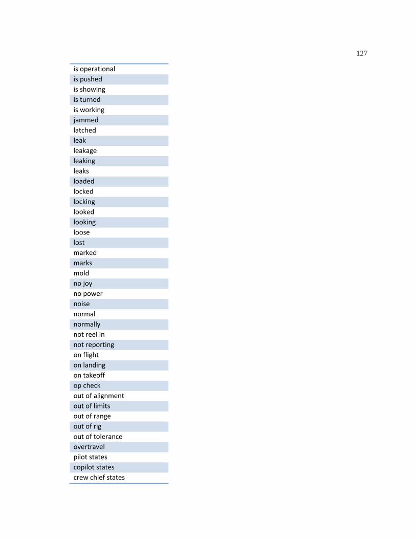
127
is operational is pushed is showing is turned is working jammed latched leak leakage leaking leaks loaded locked locking looked looking loose lost marked marks mold no joy no power noise normal normally not reel in not reporting on flight on landing on takeoff op check out of alignment out of limits out of range out of rig out of tolerance overtravel pilot states copilot states crew chief states

128
poc capt poc cpl poc gysgt poc is poc lcpl poc sgt poc ssgt pointed popped popping pops post flight postflight pre flight preflight pressure drops pulled quick quickly randomly rapidly reappears remained on remained stuck ripped rolled down rolling running rupture ruptured rust seemed sheared shorted shorting shot down showing shut down shut off slashed slow

129
slowly soft Solid spinning spins split spot stayed stays stays in steady sticking sticks stopped stops straight stripe striped stuck take off tear thin throughout flight tight trapped turned off turned on turned over turning on turns on upon inspection upon installation upon landing upon shutdown valid visible visual was low was on was working weak

130
wear were correct were low were on wet while in flight will not allow will not extend will not fold will not go will not unstow worked fine working properly works fine worn

131
Appendix B
Type MAF Codes and Descriptions
Source: U.S. Navy [190]
Type MAF Code
Description
AC ACCEPTANCE/POST-DEPOT INSPECTION CONTROL AD ASSIST MAINTENANCE ACTION AF ACCEPTANCE/POST-DEPOT INSPECTION FIX PHASE AL ACCEPTANCE/POST-DEPOT INSPECTION LOOK AT ASSIST TECHNICAL DIRECTIVE MAINT ACTION AX ACCEPTANCE/POST-DEPOT INSPECTION SINGLE WORK CENTER BC DEPRESERVATION CONTROL WORK ORDER BF DEPRESERVATION FIX PHASE MAINT ACTION BX SINGLE W/C DEPRESERVATION WORK ORDER CC CONDITIONAL INSPECTION CONTROL WORK ORDER CF CONDITIONAL INSP FIX PHASE MAINT ACTION CL CONDITIONAL INSPECTION LOOK PHASE WORK ORDER CM CANNIBALIZATION MAINTENANCE ACTION CP CORROSION PREVENTION WORK ORDER CT CORROSION TREATMENT WORK ORDER CX SINGLE W/C CONDITIONAL INSP WORK ORDER DF DAILY/PRE/POST FLT/TURNAROUND DISCREPANC DM DISCREPANCY MAINTENANCE ACTION DT DAILY/TURNAROUND DISCREPANCY ET ENGINE TD SCIR WORK ORDER FC PRESERVATION CONTROL WORK ORDER FF PRESERVATION FIX PHASE MAINT ACTION FO FACILITATE OTHER MAINTENANCE FX SINGLE W/C PRESERVATION WORK ORDER HA HOSTING ACTIVITY MAINT DOCUMENTATION IA INTRA-ACTIVITY SUPPORT IC IMC CONTROL WORK ORDER IF IMC FIX PHASE WORK ORDER IL IMC LOOK PHASE WORK ORDER MC SDLM CONTROL WORK ORDER MF SDLM FIX PHASE WORK ORDER ML SDLM LOOK PHASE WORK ORDER MX SDLM SINGLE W/C INSP WORK ORDER OC ONE TIME INSP CONTROL WORK ORDER OF ONE TIME INSP FIX PHASE WORK ORDER OL ONE TIME INSP LOOK WORK ORDER OM OTHER TYPE MAINTENANCE ACTIONS OX SINGLE W/C ONE TIME INSP WORK ORDER

132
PC PHASE CONTROL WORK ORDER PF PHASE FIX PHASE MAINTENANCE ACTION PL PHASE LOOK PHASE WORK ORDER PX SINGLE W/C PHASE/PM INSP WORK ORDER QT TD REMOVAL RT ROUTINE TASKS WORK ORDER SC SPECIAL INSPECTION CONTROL WORK ORDER SD DEPRESERVATION W/C ACTION WORK ORDER SF SPECIAL INSP FIX PHASE MAINT ACTION SL SPECIAL INSPECTION LOOK PHASE WORK ORDER SP PRESERVATION W/C ACTION WORK ORDER SX SINGLE W/C SPECIAL INSP WORK ORDER TC TRANSFER/PRE-DEPOT INSPECTION CONTROL TD TECHNICAL DIRECTIVE MAINTENANCE ACTION TF TRANSFER/PRE-DEPOT INSPECTION FIX PHASE TL TRANSFER/PRE-DEPOT INSPECTION LOOK PHASE TM TRANSIT MAINTENANCE DOCUMENTATION TS TROUBLESHOOTING MAINTENANCE ACTION TX TRANSFER/PRE-DEPOT INSPECTION SINGLE WORK CENTER WR WORK REQUEST MAINTENANCE ACTION
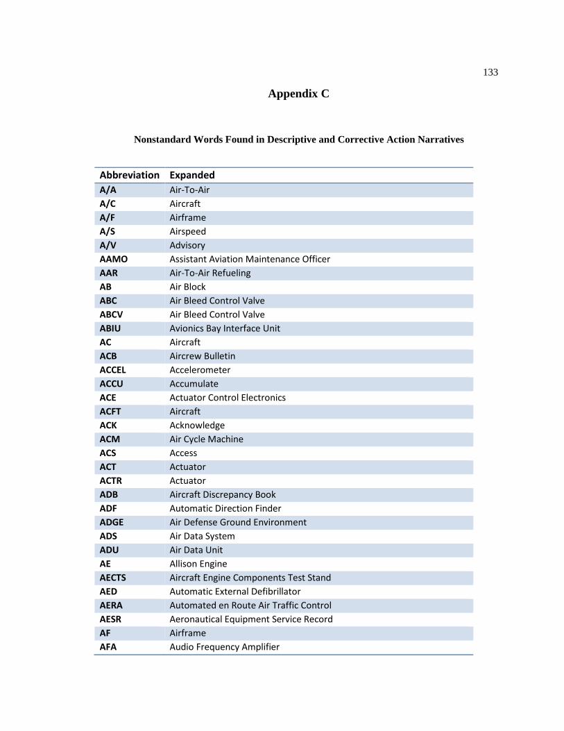
133
Appendix C
Nonstandard Words Found in Descriptive and Corrective Action Narratives
Abbreviation Expanded A/A Air-To-Air A/C Aircraft A/F Airframe A/S Airspeed A/V Advisory AAMO Assistant Aviation Maintenance Officer AAR Air-To-Air Refueling AB Air Block ABC Air Bleed Control Valve ABCV Air Bleed Control Valve ABIU Avionics Bay Interface Unit AC Aircraft ACB Aircrew Bulletin ACCEL Accelerometer ACCU Accumulate ACE Actuator Control Electronics ACFT Aircraft ACK Acknowledge ACM Air Cycle Machine ACS Access ACT Actuator ACTR Actuator ADB Aircraft Discrepancy Book ADF Automatic Direction Finder ADGE Air Defense Ground Environment ADS Air Data System ADU Air Data Unit AE Allison Engine AECTS Aircraft Engine Components Test Stand AED Automatic External Defibrillator AERA Automated en Route Air Traffic Control AESR Aeronautical Equipment Service Record AF Airframe AFA Audio Frequency Amplifier
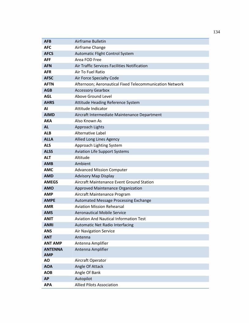
134
AFB Airframe Bulletin AFC Airframe Change AFCS Automatic Flight Control System AFF Area FOD Free AFN Air Traffic Services Facilities Notification AFR Air To Fuel Ratio AFSC Air Force Specialty Code AFTN Afternoon; Aeronautical Fixed Telecommunication Network AGB Accessory Gearbox AGL Above Ground Level AHRS Attitude Heading Reference System AI Attitude Indicator AIMD Aircraft Intermediate Maintenance Department AKA Also Known As AL Approach Lights ALB Alternative Label ALLA Allied Long Lines Agency ALS Approach Lighting System ALSS Aviation Life Support Systems ALT Altitude AMB Ambient AMC Advanced Mission Computer AMD Advisory Map Display AMEGS Aircraft Maintenance Event Ground Station AMO Approved Maintenance Organization AMP Aircraft Maintenance Program AMPE Automated Message Processing Exchange AMR Aviation Mission Rehearsal AMS Aeronautical Mobile Service ANIT Aviation And Nautical Information Test ANRI Automatic Net Radio Interfacing ANS Air Navigation Service ANT Antenna ANT AMP Antenna Amplifier ANTENNA AMP
Antenna Amplifier
AO Aircraft Operator AOA Angle Of Attack AOB Angle Of Bank AP Autopilot APA Allied Pilots Association

135
APAF All Parts Accounted For APAP Approach Path Alignment Panels APD Activity Predictor Display APLN Airplane; Automatic Position Location Navigator & Reporting APP Approach Centre / Control; Approach APPR Approximately; Approach APPROX Approximately APPX Approximately APROX Approximately APU Auxiliary Power Unit APX Approximately AR Arial Refueling ARC Airborne Radio Communications ARM Air Data System Report Message ARMA Adaptability Rating For Military Aviation ARN Aviation Reference Number ARRP Air-To-Air Refueling Probe ASAP As Soon As Possible ASC Air Safety Committee; Ascending ASE Aircraft Survivability Equipment ASHE Aircraft Salvage Handling Equipment ASI Air Speed Indicator ASR Air Safety Report ASSY Assembly ATA Actual Time Of Arrival; Air Transport Association ATAF All Tools Accounted For ATC Air Traffic Control ATF Auxiliary Tank Fuel ATSN Air Traffic System Network ATT Attitude Indicator AU Airborne Unit AUTO Automatic AUX Auxiliary AV Avionics AVB Avionics Bulletin AVC Avionics Change AVG Average AVI Avionics AVR Availability Information Request Details AVSS Active Vibration Suppression System AYB Accessory Bulletin

136
AYC Accessory Change B/F Blade Fold B/U Backup BA Barometric Altitude BAL Ballast BATT Battery BB Blowback BC Because BD Bearing And Distance BDD Blade De-Ice Distributor BF Before BFCU Blade Fold Control Unit BFWS Blade Fold Wing Stow BIT Built-In Test BKR Breaker BL Below BLD Blade BLK Black BLWR Blower BRG Bearing BRK Brake BTW Between BTWN Between BU Backup BUNO Bureau Number BYP Bypass CAC Continuous Adjustment Control CAGE Commercial And Government Entity CAL Calibration CALC Calculated CANC Cancel CANN Cannibalization CAPT Captain CB Circuit Breaker CBP Circuit Breaker Panel CC Crew Chief CCA Central Control Actuator CCDL Cross Channel Data Link CCFDA Cockpit Control Feel Drive Actuator CCPT Cockpit Control Position Transducer CCTDA Cockpit Control Thrust Drive Actuator

137
CCU Computer Control Unit CDD Central De-Ice Distributor CDI Course Deviation Indicator CDP Compressor Discharge Pressure CDT Compressor Discharge Temperature CDU Control Display Unit CERT Certification CFG Constant Frequency Generator CG Center Of Gravity CH Cargo Helicopter CHG Change CHK Check CIU Cockpit Interface Unit CK Check CKPT Cockpit CLR Clear CMDR Commander CMDS Cockpit Management Display System CMPRSS Compressor CMPTR Computer CMPTRS Computers CMS Cockpit Management System CNAF Commander, Naval Air Forces CNTR Center CNTRL Control CO PILOT Copilot COM Communications COMM Communications COMSEC Communications Security CONFIG Configuration CONN Connect CONT Control CONTR Control CONV Conversion CO-PILOT Copilot CORR Corrosion CP Control Panel CPC Cabin Pressure Controller CPL Current Flight Plan CPLD Coupled CPLT Copilot
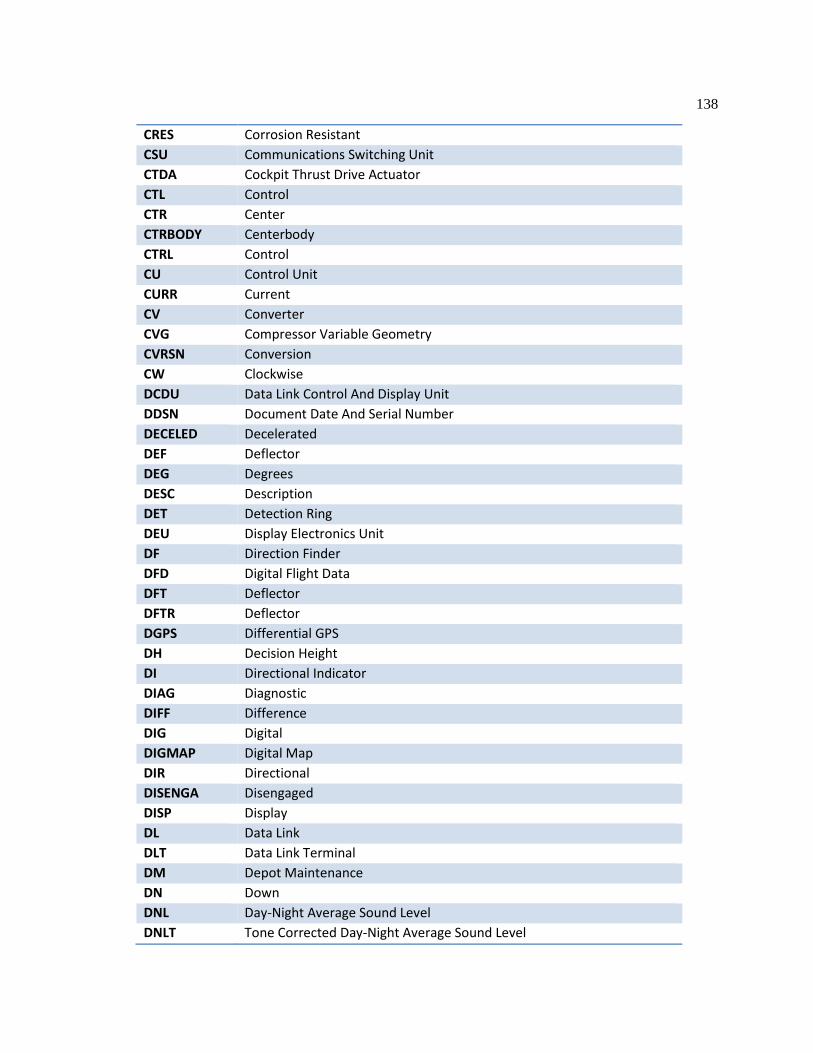
138
CRES Corrosion Resistant CSU Communications Switching Unit CTDA Cockpit Thrust Drive Actuator CTL Control CTR Center CTRBODY Centerbody CTRL Control CU Control Unit CURR Current CV Converter CVG Compressor Variable Geometry CVRSN Conversion CW Clockwise DCDU Data Link Control And Display Unit DDSN Document Date And Serial Number DECELED Decelerated DEF Deflector DEG Degrees DESC Description DET Detection Ring DEU Display Electronics Unit DF Direction Finder DFD Digital Flight Data DFT Deflector DFTR Deflector DGPS Differential GPS DH Decision Height DI Directional Indicator DIAG Diagnostic DIFF Difference DIG Digital DIGMAP Digital Map DIR Directional DISENGA Disengaged DISP Display DL Data Link DLT Data Link Terminal DM Depot Maintenance DN Down DNL Day-Night Average Sound Level DNLT Tone Corrected Day-Night Average Sound Level

139
DOC Document DODIC Department Of Defense Identification Code DOM Domestic; Directed DR Door DRAT Defect Reliability Analysis Tool DS Data Source DSBL Disable DSI Data Source Interface DSIU Drive System Interface Unit DSRA Docking Selected Restricted Availability DT Date DTD Data Transfer Device DTED Digital Terrain Elevation Display DTG Date-Time Group DTM Data Transfer Module DU Display Unit DV Data Validation DW Dual Wheels DWN Down E3 Electromagnetic Environmental Effects EA Each EAC Emergency And Abnormal Checklist EAPS Engine Air Particle Separator EB Eastbound ECL Engine Control Lever ECLS Electrical Cargo Loading System ECM Electronic Countermeasures ECS Environmental Control System ECU Environmental Control Unit ED Estimated Departure EDD Electronic Data Display EELS Emergency Egress Lighting System EI Engineering Information EICAS Engine Instrument And Crew Alerting System EID Engine Instrument Display EKMS Electronic Key Management System EL Electroluminescent ELEC Electrical ELEV Elevator ELS Emergency Lubrication System EMC Electromagnetic Compatibility

140
EMCON Emissions Control (Radio Silence) EMER Emergency EMERG Emergency EMI Electromagnetic Interference EMU Event Monitoring Unit EMV Electromagnetic Vulnerability ENG Engine ENV Environmental EPGS Electrical Power Generating System ERAC Electronic Rapid Action Change EW Electronic Warfare EWS Electronic Warfare System EXH Exhaust EXP Expected F (C) Communication Built-In Test Failure F (P) Periodic Built-In Test Failure F (T) Initiated Built-In Test Failure FADEC Full Authority Digital Engine Control FAIL Failure FCC Flight Control Computer FCCS Forward Cabin Control Station FCF Functional Check Flight FCS Flight Control System FF Fuel Flow FLAP Flaperon FLD Fold FLIR Forward-Looking Infrared FLT Flight FMU Fuel Management Unit FOD Foreign Object Debris FOM Facilitate Other Maintenance; Flight Operations Manual FP Flight Plan FPMU Fuel Pump Metering Unit FR From; Fuel Remaining FRAG Fragmentation FREQ Frequency FSR Field Service Representative FST Fleet Support Team FTIP Flight Test Interface Panel FTP Functional Test Procedure FWD Forward
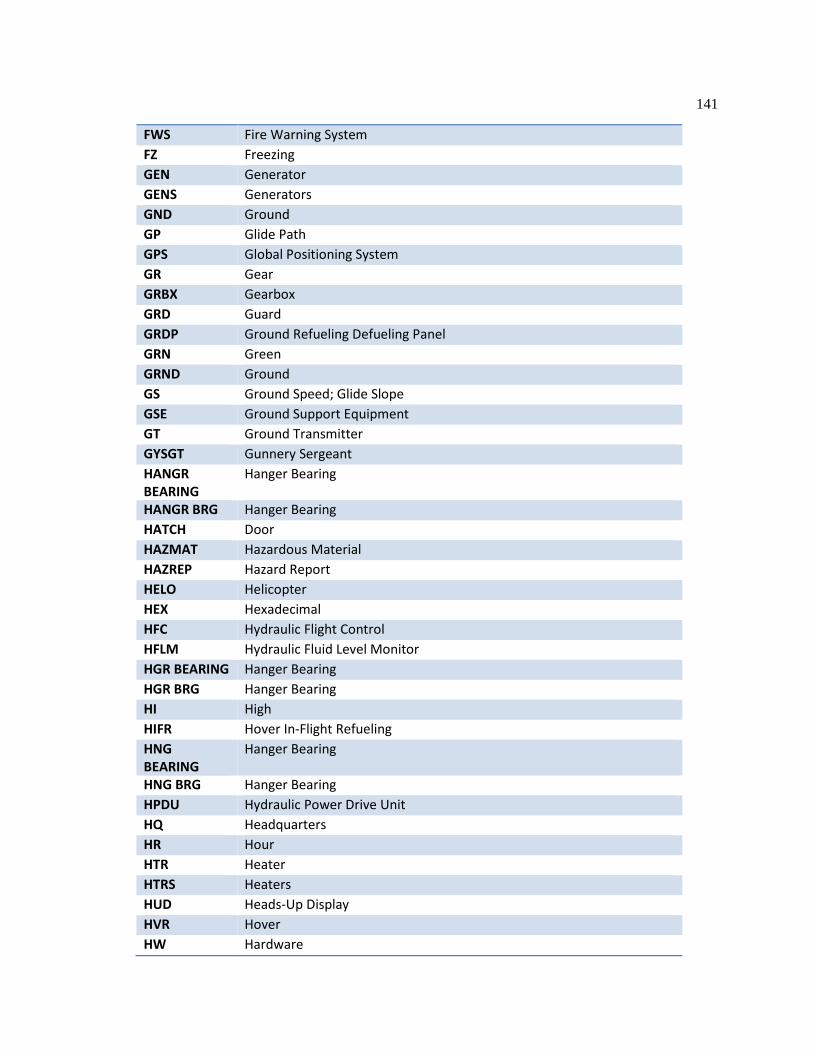
141
FWS Fire Warning System FZ Freezing GEN Generator GENS Generators GND Ground GP Glide Path GPS Global Positioning System GR Gear GRBX Gearbox GRD Guard GRDP Ground Refueling Defueling Panel GRN Green GRND Ground GS Ground Speed; Glide Slope GSE Ground Support Equipment GT Ground Transmitter GYSGT Gunnery Sergeant HANGR BEARING
Hanger Bearing
HANGR BRG Hanger Bearing HATCH Door HAZMAT Hazardous Material HAZREP Hazard Report HELO Helicopter HEX Hexadecimal HFC Hydraulic Flight Control HFLM Hydraulic Fluid Level Monitor HGR BEARING Hanger Bearing HGR BRG Hanger Bearing HI High HIFR Hover In-Flight Refueling HNG BEARING
Hanger Bearing
HNG BRG Hanger Bearing HPDU Hydraulic Power Drive Unit HQ Headquarters HR Hour HTR Heater HTRS Heaters HUD Heads-Up Display HVR Hover HW Hardware
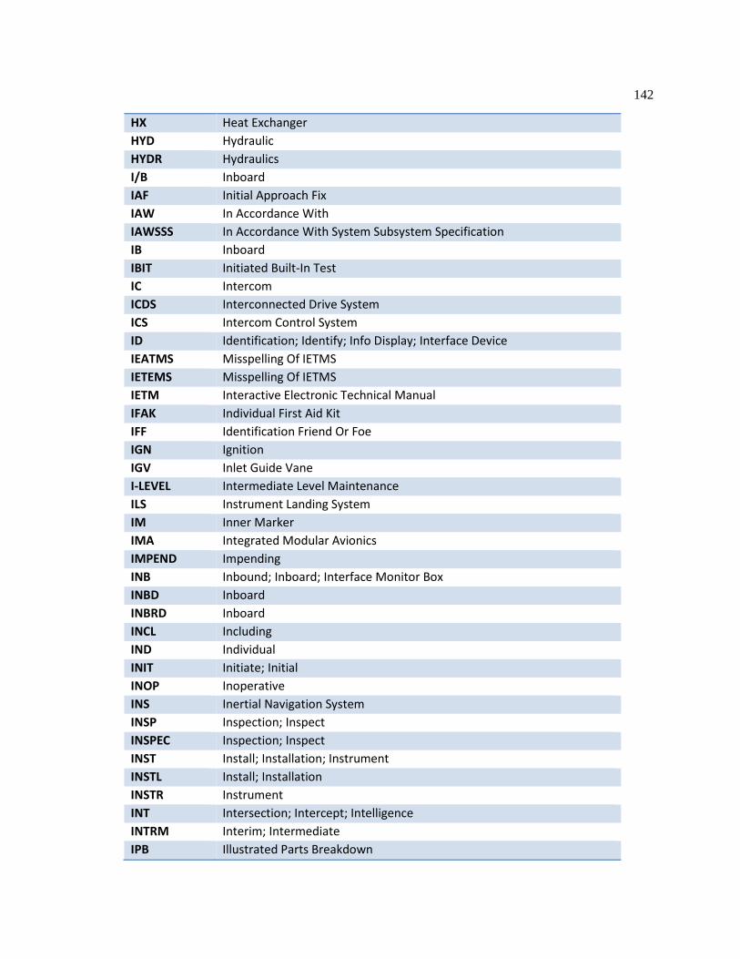
142
HX Heat Exchanger HYD Hydraulic HYDR Hydraulics I/B Inboard IAF Initial Approach Fix IAW In Accordance With IAWSSS In Accordance With System Subsystem Specification IB Inboard IBIT Initiated Built-In Test IC Intercom ICDS Interconnected Drive System ICS Intercom Control System ID Identification; Identify; Info Display; Interface Device IEATMS Misspelling Of IETMS IETEMS Misspelling Of IETMS IETM Interactive Electronic Technical Manual IFAK Individual First Aid Kit IFF Identification Friend Or Foe IGN Ignition IGV Inlet Guide Vane I-LEVEL Intermediate Level Maintenance ILS Instrument Landing System IM Inner Marker IMA Integrated Modular Avionics IMPEND Impending INB Inbound; Inboard; Interface Monitor Box INBD Inboard INBRD Inboard INCL Including IND Individual INIT Initiate; Initial INOP Inoperative INS Inertial Navigation System INSP Inspection; Inspect INSPEC Inspection; Inspect INST Install; Installation; Instrument INSTL Install; Installation INSTR Instrument INT Intersection; Intercept; Intelligence INTRM Interim; Intermediate IPB Illustrated Parts Breakdown

143
IPS Inlet Particle Separator IR Infrared IRAC Interim Rapid Action Change IRS Infrared Suppression IRU Interface Receptacle Unit IS Interface Specification; Intermediate System ISC Intercom Set Controller ISO Isolation IYAOYAS "If You Ain't Ordnance You Ain't S___" (Aviation Ordnancemen Slogan) JAN January; Joint Army-Navy JASS JVX Application Systems Software JCN Job Control Number JUL July JUN June JVX Joint Services Vertical Lift Aircraft Experimental KCAS Knots Calibrated Airspeed KM Kilometer KTS Knots KYBD Keyboard L Left L/H Left LASER Light Amplification By Stimulated Emission Of Radiation LAT Lateral LB Pound LBS Pounds LCK Lock LCPL Lance Corporal LDG Landing Gear LDV Laser Doppler Velocimeter LE Leading Edge LES Leading Edges LEV Level; Lever LFT Left LG Landing Gear LGCU Landing Gear Control Unit LH Left Hand LHEAPS Left-Hand Engine Air Particle Separator LHOB Left-Hand Outboard LK Lock LND Landing LNK Air Link

144
LOC Location LOS Line Of Sight LP Low Pressure LPRGB Left Proprotor Gearbox LRIP Low Rate Initial Production LRU Line Replaceable Unit LT Light; Left Turn; Lieutenant LTAGB Left Tilt-Axis Gearbox LTCOL Lieutenant Colonel LTR Later LTS Lights LUBE Lubrication LVDT Linear Variable Differential Transformer LVL Level LW Landing Weight; Low LWGG Lightweight Gas Generator LWINS Light Weight Inertial Navigation System LWR Lower LZ Landing Zone MAF Maintenance Action Form MAGR Miniature Airborne Global Positioning System Receiver MAINT Maintenance MAJ Major MAJCOM Major Commander MALS Medium Intensity Approach Light System MAN Manual MAR March MARTS Mean Active Repair Time MAX Maximum MB Megabyte; Millibars MBIT Maintenance Built-In Test MC Mission Computer MCL Master Configuration List MCN Mission Control Number MCP Maximum Continuous Power MDR Master Data Record MDU Multiplexer Decoder Unit MECH Mechanic MEI Multi Engine Instructor MEM Memory MEU Marine Expeditionary Unit

145
MEW Microwave Early Warning MEWS Microwave Early Warning System MFD Multifunction Display MFG Manufacturing MFR Memorandum For The Record MGT Measured Gas Temperature MH Man Hours; MI Mile MIC Microphone MID Middle MIDWING Mid-Wing MIL Military MIN Minimum; Minute MINS Minimums; Minutes MIPCU Master Ice Protection Control Unit MK Mark ML Maintenance Level MLG Main Landing Gear MM Middle Marker MMCO Maintenance Material Control Officer MMR Multimode Receiver MOD Modification MRC Maintenance Requirement Card MSG Message MSL Mean Sea Level MSN Mission MT Mount MTR Module Test And Repair MULTI Multiple MV-22B Multi-Mission Vertical Takeoff And Landing 22 Series B MW Mid-Wing MWGB Mid-Wing Gearbox MWS Missile Warning System NAC Nacelle NADEP Naval Aviation Depot NALCOMIS Naval Aviation Logistics Command Management Information System NARF Naval Air Rework Facility NAS Naval Air Station NATOPS Naval Air Training And Operational Procedures Standardization NAV Navigation NAVAIR Naval Air Systems Command

146
NAWC Naval Air Warfare Center NDI Nondestructive Inspection NG Gas Generator Speed NIPC Nacelle Ice Protector Controller NIPCU Nacelle Ice Protection Control Unit NIU Nacelle Interface Unit NLG Nose Landing Gear NLT Not Later Than NM Nautical Miles NOAP Navy Oil Analysis Program NORM Normal NOV November NP Power Turbine Speed NPC Navy Personnel Command NR Rotor Speed NRFI Not Ready For Issue NSN National Stock Number; NATO Stock Number NUM Number; Numerical NVD Night Vision Device NVG Night Vision Goggles NW Nose Wheel NWS Nose Wheel Steering NXT Next O/B Outboard O2N2 Oxygen Nitrogen System OA Operational Analysis; Operational Availability; Object-Oriented Analysis OAP Offset Aiming Point OAT Outside Air Temperature OB Outboard OBD Outboard OBE Overcome By Events OBIGGS Onboard Inert Gas Generating System OBOGGS Onboard Oxygen Gas Generating System OBOGS Onboard Oxygen Generating System OC Operational Capability OCT October OCU Oil Conditioning Unit OEM Original Equipment Manufacturer OFP Operational Flight Program OOMA Optimized Organizational Maintenance Activity OP Operation
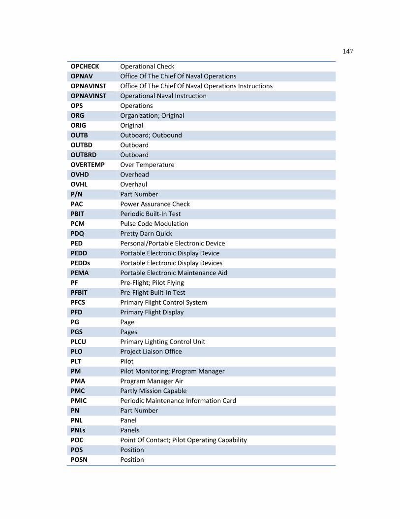
147
OPCHECK Operational Check OPNAV Office Of The Chief Of Naval Operations OPNAVINST Office Of The Chief Of Naval Operations Instructions OPNAVINST Operational Naval Instruction OPS Operations ORG Organization; Original ORIG Original OUTB Outboard; Outbound OUTBD Outboard OUTBRD Outboard OVERTEMP Over Temperature OVHD Overhead OVHL Overhaul P/N Part Number PAC Power Assurance Check PBIT Periodic Built-In Test PCM Pulse Code Modulation PDQ Pretty Darn Quick PED Personal/Portable Electronic Device PEDD Portable Electronic Display Device PEDDs Portable Electronic Display Devices PEMA Portable Electronic Maintenance Aid PF Pre-Flight; Pilot Flying PFBIT Pre-Flight Built-In Test PFCS Primary Flight Control System PFD Primary Flight Display PG Page PGS Pages PLCU Primary Lighting Control Unit PLO Project Liaison Office PLT Pilot PM Pilot Monitoring; Program Manager PMA Program Manager Air PMC Partly Mission Capable PMIC Periodic Maintenance Information Card PN Part Number PNL Panel PNLs Panels POC Point Of Contact; Pilot Operating Capability POS Position POSN Position

148
POT Potentiometer PPB Provisioning Parts Breakdown PQDR Product Quality Deficiency Report PREF Preferred PREPED Misspelling Of Prepped PRESS Pressure PRF Pulse Repetition Frequency PRG Preamble Generator PRGB Proprotor Gearbox PRI Primary PROP Proprotor PROPRTR Proprotor PROT Protection PRPRTR Proprotor PRQ Pilot Request PRTR Proprotor PS Power Supply PSI Pounds Per Square Inch PSIG Pounds Per Square Inch Gauge PSO Pressure Shutoff PSOV Pressure Shutoff Valve PSS Processor Support Software PT Point PTCH Pitch PTT Push To Talk PWR Power QA Quality Assurance QE Quote Estimate QEC Quick Engine Change QM Mast Torque QTY Quantity R Right R/H Right R/O Right Outboard R/T Receiver Transmitter RAD Radar RADALT Radar Altimeter RB Right Bank; Rotor Brake RCCB Remote Controlled Circuit Breaker RCU Remote Control Unit RCVR Receiver

149
RDR Radar RDY Ready RE Recent (Weather); Right Engine RECIRC Recirculating REF Reference REG Regulation REP Receiver Exciter-Processor; Report; Repelling REQ Required REQD Required RES Radio Engineering Services; Radar Environment Simulator; Residue RET Return RETQ Retorque RETQED Retorqued REV Revision RF Radio Frequency RFI Radio Frequency Interference RFIS Radio Frequency Information System RFL Refuel RFU Radio Frequency Unit RG Range RGR Ranger; Rapid Ground Refueling RH Right-Hand RHOB Right-Hand Outboard RHS Reserve Headquarters System RI Route Intercept RIFIS Remote Indication Frequency Indicator System RLY Relay RM Replaceable Module RMU Removable Memory Unit RMVL Removal RMWS Ramp Mounted Weapon System ROC Rate Of Climb ROD Rate Of Descent RPM Revolutions Per Minute RPRGB Right Proprotor Gearbox RPU Rotor Phasing Unit RSVR Reservoir RTAGB Right Tilt-Axis Gearbox RTB Rotor, Track, And Balance RTN Return RTR Rotor
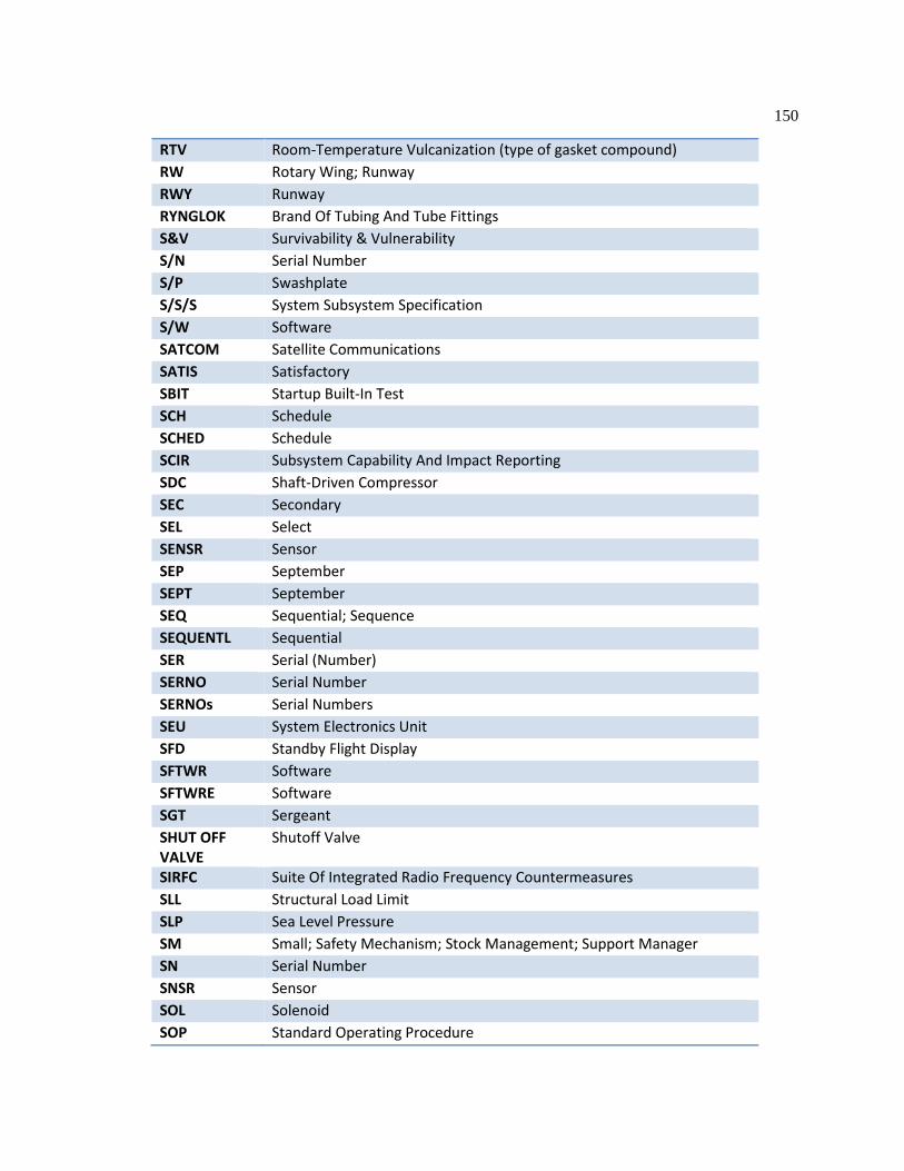
150
RTV Room-Temperature Vulcanization (type of gasket compound) RW Rotary Wing; Runway RWY Runway RYNGLOK Brand Of Tubing And Tube Fittings S&V Survivability & Vulnerability S/N Serial Number S/P Swashplate S/S/S System Subsystem Specification S/W Software SATCOM Satellite Communications SATIS Satisfactory SBIT Startup Built-In Test SCH Schedule SCHED Schedule SCIR Subsystem Capability And Impact Reporting SDC Shaft-Driven Compressor SEC Secondary SEL Select SENSR Sensor SEP September SEPT September SEQ Sequential; Sequence SEQUENTL Sequential SER Serial (Number) SERNO Serial Number SERNOs Serial Numbers SEU System Electronics Unit SFD Standby Flight Display SFTWR Software SFTWRE Software SGT Sergeant SHUT OFF VALVE
Shutoff Valve
SIRFC Suite Of Integrated Radio Frequency Countermeasures SLL Structural Load Limit SLP Sea Level Pressure SM Small; Safety Mechanism; Stock Management; Support Manager SN Serial Number SNSR Sensor SOL Solenoid SOP Standard Operating Procedure

151
SOV Shutoff Valve SP Swashplate SPA Swashplate Actuator SPNS Sponson SPNSN Sponson SPSN Sponson SQD Squadron SQDN Squadron SRCH Search SRUT Shop-Replaceable Unit SS Segment Specification SSGT Staff Sergeant SSS System Subsystem Specification STA Station STAB Stabilizer STAT Status STBY Standby STRL Structural SUB Substitution SUBS Substitutions SUBSEQ Subsequent SUPPY Supplementary SW Switch SWA Swashplate Actuator SWASHPLT Swashplate SWP Swashplate SWPL Swashplate SWPLT Swashplate SYS System SYST System T Temperature T/M/S Type Model Series T/O Takeoff T/S Troubleshoot TACAN Tactical Air Navigation TAGB Tilt-Axis Gearbox TARG Target TBC To Be Confirmed TBD To Be Determined TCL Thrust Control Lever TCTO Time Compliance Tech Order

152
TD Technical Directive TECH Technical TEE Task-Essential Equipment TEMPS Temperatures TFOA Things Falling Off Aircraft TFOM Time for Other Maintenance TFOW Thin-Film Optical Waveguide TFU Turret Forward Looking Infrared Unit TH True Heading TK Tank TORQ Torque TOW Take-Off Weight TPUMP Transfer Pump TQ Torque TQD Torqued TQED Torqued TQS Torques TRANS Transmitter TREND AMP Trend Amplitude TRI Type-Rating Indicator TRQ Torque TRQD Torqued TS Technical Specs; Technical Supplement TSN Time Since New TYCOM Type Commander UHF Ultra High Frequency UNS Unified Numbering System UPPR Upper UPR Upper UPS Uninterruptible Power Supply UTIL Utility UUT Unit Under Test UV Ultra-Violet VAL Value VDC Volts Direct Current VEL Velocity VERT Vertical VESTL V-22 Engineering System Test Laboratory VF Visual Flying VFG Variable Frequency Generator VHF Very High Frequency
153
VIB Vibration VIBE Vibration VL Vertical Landing VLV Valve VMS Vehicle Management System VMX Marine Tiltrotor Operational Test And Evaluation Squadron VN Vertical Navigation VOL Volume VOR Vhf Omnidirectional Range VOX Voice-Activated Switch VS Stalling Velocity; Vertical Speed VSLED Vibration, Structural Life, And Engine Diagnostics VT Vertical Takeoff VTOL Vertical Takeoff And Landing VV Vertical Visibility W Watts; West W/C Work Center W/S Windshield W/W Windshield Wiper WA Work Authorization WB Weight & Balance WC Work Center WCA Warning, Caution, Advisory WFPC Wing Fire Protection Controller WFPS Wing Fire Protection System WG Wing WHA Wiring Harness Assembly WHT White; Weapon Handling Test WIA Wiring Interface Assembly WIU Wing Interface Unit WO Without; Warrant Officer WOW Weight On Wheels WP Waypoint WRA Weapons Replaceable Assembly WRAs Weapons Replaceable Assemblies WRSD Wire Repair Source Data WT Weight WUC Work Unit Code XD Transducer XDCR Transducer XDUCER Transducer

154
XFER Transfer XFR Transfer XO Executive Officer XT Crosstie XTIE Crosstie XW Cross-Wind YR Year YYMMDD Date ZV Zero Velocity

VITA
Joseph T. Bernardo, Ph.D. E-mail: [email protected]
Education: Ph.D., Information Sciences and Technology, Pennsylvania State University 2014 M.S., Electrical Engineering, Pennsylvania State University 1988 B.S., Electrical Engineering, Pennsylvania State University 1986
Biographical Sketch: Joseph T. Bernardo is a principal investigator. He has twenty-six years of experience in research and development (R&D) in the fields of information science, computer science, and electrical engineering.
Experience: Applied Research Lab at Penn State University 2009 – present
Principal Investigator
Raytheon, AT&T, and Lucent Technologies 1988 – 2009 Systems Engineer
Selected Publications: Bernardo, J. T., 2014. Application of the JDL Model to Hard/Soft Fusion in the
Condition Monitoring of Aircraft, SPIE Defense, Security, and Sensing Conference, Baltimore, MD. May 5 - 8, 2014.
Bernardo, J. T., 2013. A Methodology for Hard/Soft Fusion in the Condition Monitoring of Aircraft, SPIE Defense, Security, and Sensing Conference, Baltimore, MD. April 29 - May 2, 2013.
Bernardo, J. T., 2011. Partition Exchange Loading Improves Condition-Based Maintenance. ASNE Fleet Maintenance and Modernization Symposium. San Diego, CA. August 30-31, 2011.
Bernardo, J. T., 2011. Architecture for Communicating and Processing Parametric Data Collected on Military Platforms. Report for Program Manager Autonomic Logistics, USMC, April 7, 2011.
Bernardo, J. T., 2007. Can Virtual Private Database Implement PL3 Multi-Level Security and Dissemination Controls? Raytheon 6th Annual Software Systems Symposium. Richardson, TX, April 30- May 3, 2007.
Bernardo, J. T. and Bose, N.K., 1988. Phase and Magnitude Retrieval with the Knowledge of One Corner Point of a Finite Support Digital Image. Proceedings of the 1988 Conference on Information Sciences and Systems. 22 (1988), 11-15.
Certifications: FAA Commercial Pilot, Instrument-Rated 2009 – present Oracle Certified Professional 2005 – present
Memberships: Member, Institute of Electrical and Electronics Engineers (IEEE) 1986 – present Chairman, Supervisory Committee of the SPE Federal Credit Union 2006 – 2008