hardware installation guide - crcbe.ca · pdf filehardware installation guide). ... ecb-400...
TRANSCRIPT
www.distech-controls.com 1/14
1. Product Description
This document describes the hardware installation procedures for the ECB series BACnet controllers.
The Distech Controls BACnet controllers are designed to control and monitor various HVAC equipment such as roof top units, air handling units as well as chillers, boilers, and central plant applications. Moreover, these controllers are suitable for any lighting control and power measurement applications. This product line includes the following controllers: ECB-203, ECB-300, ECB-400 Series, and ECB-600 Series.
For 50 Series controllers (models equipped with an operator interface), refer to the 50 Series Controller User Guide for how to use this interface.
The ECB-600 Series are compatible with the IO Extension Module product line, which includes the following modules: ECx-400, ECx-410, and ECx-420 (refer to the ECx-400 series IO Extension Module Hardware Installation Guide).
Each controller uses the BACnet® MS/TP LAN communication
protocol.
This document describes the hardware installation procedures for the following controllers: ECB-203 Series, ECB-300 Series, ECB-400 Series, and ECB-600 Series controllers only.
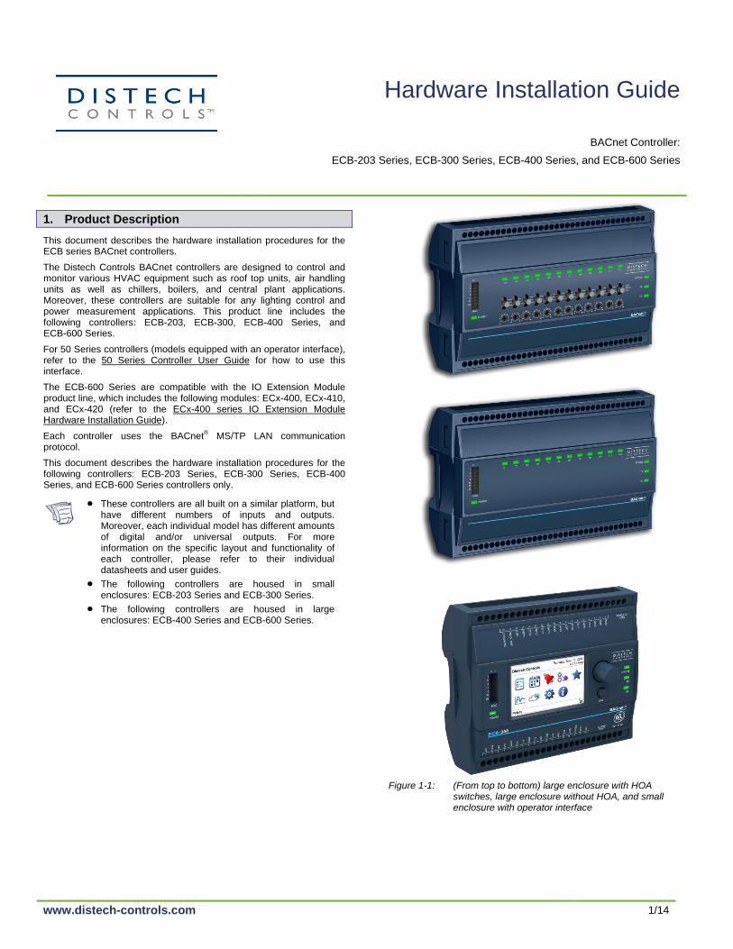
These controllers are all built on a similar platform, but have different numbers of inputs and outputs. Moreover, each individual model has different amounts of digital and/or universal outputs. For more information on the specific layout and functionality of each controller, please refer to their individual datasheets and user guides.
The following controllers are housed in small enclosures: ECB-203 Series and ECB-300 Series.
The following controllers are housed in large enclosures: ECB-400 Series and ECB-600 Series.
Figure 1-1: (From top to bottom) large enclosure with HOA switches, large enclosure without HOA, and small enclosure with operator interface
Hardware Installation Guide
BACnet Controller:
ECB-203 Series, ECB-300 Series, ECB-400 Series, and ECB-600 Series

2/14
2. General Installation Requirements
For proper installation and subsequent operation of each controller, pay special attention to the following recommendations:
- It is recommended that the controller(s) be kept at room temperature for at least 24 hours before installation to allow any condensation that may have accumulated due to low temperature during shipping/storage to evaporate.
- Upon unpacking the product, inspect the contents of the carton for shipping damages. Do not install damaged controllers.
- Avoid areas where corroding, deteriorating or explosive vapors, fumes or gases may be present.
- Allow for proper clearance around the controller’s enclosure, wiring terminals, and MAC Addressing switches to provide easy access for hardware configuration and maintenance, and to ventilate heat generated by the controller.
- Orient the controller with the ventilation slots and power supply/output terminal block connectors towards the top to permit proper heat dissipation. When installed in an enclosure, select one that provides sufficient surface area to dissipate the heat generated by the controller and by any other devices installed in the enclosure. A metal enclosure is preferred. If necessary, provide active cooling for the enclosure.
- The controller’s datasheet specifies the power consumption (amount of heat generated), the operating temperature range, and other environmental conditions the controller is designed to operate under.
- Ensure that all equipment is installed according to local, regional, and national regulations.
- The controller’s plastic enclosure has a back plate that is separable from the front plate allowing the back plates (with the connectors) to be shipped directly to the installation site while all the engineering is done in the office.
- Do not drop the controller or subject it to physical shock.
- If the controller is used and/or installed in a manner not specified by Distech Controls, the functionality and the protection provided by the controller may be impaired.
Any type of modification to any Distech Controls product will void the product’s warranty.
Take special care to keep the front and back plate
aligned when separating and joining them.
Before installation of the Wireless Receiver, verify that local communication regulations allow the installation of wireless devices that operate at a frequency of 315 MHz or 868.3MHz. Refer to the Open-to-Wireless™ Solution Guide for more information.
Take reasonable precautions to prevent electrostatic discharges to the controller when installing, servicing or operating the controller. Discharge accumulated static electricity by touching one’s hand to a securely grounded object before working with the controller.
3. General Wiring Recommendations
Turn off power before any kind of servicing.
- All wiring must comply with electrical wiring diagrams as well as national and local electrical codes.
- To connect the wiring to a controller, use the terminal connectors. It is recommended to remove the front plate from the back plate to facilitate the wiring process, however it is possible to do all wiring with the front and back plates together. Use a small flat screwdriver to tighten the terminal connector screws once the wires have been inserted.
- Comply with all BACnet network and power supply guidelines outlined in the Network Guide.
- Power type cables (i.e. for power, 3-wire voltage and current inputs and outputs) should be kept apart from other types of wiring to avoid any ambient noise transmission to other wires.
- The board connectors accept wires or flat cables ranging from 22 to 14AWG (0.644 to 1.630mm diameter) per pole. However, power cables must be between 18 and 14AWG (1.024 to 1.630mm diameter).
- Do not connect the universal inputs, analog/digital outputs or common terminals to earth or chassis ground (unless stated otherwise).
- Keep all wires away from high speed data transmission cables (for example, Ethernet, etc.).
- Keep input and output wiring in conduits, trays or close to the building frame if possible.
4. Mounting Instructions
Each controller can be mounted on a DIN rail to speed up the installation procedure. They are also equipped with two mounting holes 0.25” x 0.165” (6.35mm x 4.191mm). The controller can be mounted in a panel or on a wall by using appropriate screw types (use sheet metal, thread forming, or self-tapping screws accordingly).
DIN Rail-Mounted Installation
1. Ensure the DIN rail is properly mounted on the wall. 2. Simply clip controller onto the DIN rail.
Figure 4-1: DIN rail-mounted controller
Wall-Mounted Installation
1. Open the controller by separating the front and back plate while pressing on the side clips.
2. Use the back plate’s mounting holes to mark the location of any holes that need to be drilled.
3. Drill the holes. 4. Clean the surface and mount the controller using the appropriate
screw types.
Figure 4-2: Wall-mounted controller

3/14
5. Controller Dimensions
Figure 5-1: (From top to bottom) rear view of the large enclosure, rear view of the small enclosure and side view of the large and small enclosure
6. Power Wiring
Voltage: 24VAC/DC; ± 15%, Class 2
This is a Class 2 Product. Use a Class 2 transformer only (rated at 100VA or less at 24VAC) to power the controller(s).
The Network Guide provides extensive information and requirements for powering a controller that uses a BACnet network for communications. It can be downloaded from our website.
It is recommended to wire only one controller per 24VAC transformer.
If only one 24VAC transformer is available, determine the maximum number of controllers that can be supplied using the following method to determine the required power transformer capacity:
- Add up the maximum power consumption of all controllers including external loads and multiply this sum by 1.3.
- If the resulting number is higher than 100VA, use multiple transformers.
Use an external fuse on the 24VAC side (secondary side) of the transformer, as shown in Figure 6-1 and Figure 6-2, to protect all controllers against power line spikes.
Maintain consistent polarity when connecting controllers and devices to the transformer. One terminal on the secondary side of the transformer must be connected to the building’s ground. All 24V COM terminals of all controllers and peripherals throughout the BACnet MS/TP network must be connected to the grounded transformer terminal as shown in Figure 6-1 and Figure 6-2. This ensures that the 24V COM terminals of all devices connected to any BACnet MS/TP bus in the building are at the same potential.
A mechanical ground is unacceptable: Do not use a pipe, conduit, or duct work for a ground. The power supply must have a dedicated ground wire that comes from the main electrical supply panel.
Failure to maintain consistent polarity throughout the entire BACnet MS/TP network will result in a short circuit and/or damage to the controller! The COM terminals of the controller are internally wired to the 24V COM terminal of the power supply. Connecting a peripheral or another controller to the same transformer without maintaining polarity between these devices will cause a short circuit.
Controller 2 Transformer
Controller 1
AC
24V AC24V COM
Fuse: 4 A Max.
Fast Acting
24 VAC
Electrical System Ground
- At Transformer Only
24V AC24V COM
Figure 6-1: Power wiring – AC
Controller 2
Controller 1
24V AC/DC24V COM
Fuse: 4 A Max.
Fast Acting
Electrical System Ground
- At Power Supply Only
24V AC/DC24V COM 24 VDC
Figure 6-2: Power wiring – DC

4/14
7. Configuration Jumper Location and Identification
Controllers have the following onsite configurable jumpers.
* Factory-default positions
Subnet
Port
Wireless
Port
BACnet MS/TP Network EOL
TerminationEOL Off
(Disabled)*
EOL On
(Enabled)
Net Port
Figure 7-1: ECB-203 Controller Jumper Locations
Net Port
* Factory-default positions
BACnet MS/TP Network Board
BACnet MS/TP Network EOL
Termination
EOL Off
(Disabled)
EOL On
(Enabled)
Universal Outputs (UO)
0-10V / 0-20mA Select
0-10V 0-20mA
Subnet
Port
Wireless
Port
Universal Inputs (UI)
0-20mA Enable / Disable
0-20mA
Disable
0-20mA
Enable
Figure 7-2: ECB-300 Controller Jumper Locations
* Factory-default positions
BACnet MS/TP Network Board
BACnet MS/TP Network
EOL Termination
EOL Off
(Disabled)*
EOL On
(Enabled)
Universal Outputs (UO)
0-10V / 0-20mA Select
0-10V* 0-20mA
Universal Inputs (UI)
0-20mA Enable / Disable0-20mA
Disable*
0-20mA
Enable
ECB-600 ONLY: Subnetwork
EOL Termination
Subnet
Port
EOL Off
(Disabled)*
EOL On
(Enabled)
EOL Off
(Disabled)*
EOL On
(Enabled)
OR
Wireless
Port
Typical locations: Quantity may vary according to controller model
Net Port
Figure 7-3: ECB-400 Series and ECB-600 Series Controller Jumper Locations
8. Input Wiring
Each controller has physical connections for inputs (marked as UIx) that are configured in EC-gfxProgram. Each input can be configured for digital, resistive, current, voltage, or pulse signals. Input types must be configured properly in software to ensure proper input readings.
Table 8-1: Controller Input Support
Controller Fast and Slow Pulse Inputs support
Current Input Jumper support: 0 to 10VDC / 0 to 20mA
50Hz: 10ms minimum ON/OFF (Fast Pulse)
1Hz: 500ms minimum ON/OFF (Slow Pulse)
ECB-203 None UI1 to UI6 None
ECB-300 UI1 to UI4 UI5 to UI10 Yes; see Figure 8-8 and Section 7.
ECB-400 Series UI1 to UI4 UI5 to UI12
ECB-600 Series UI1 to UI4 UI5 to UI16
Before connecting sensor to the controller, refer to the installation guide of the equipment manufacturer.
For a wire length less than 75’ (23m), either a shielded or unshielded 18AWG wire may be used.
For a wire up to 200’ (61m) long, a shielded 18AWG wire is recommended.
The shield of the wire should be grounded on the controller side and the shield length should be kept as short as possible.
Wiring Digital Inputs
This input configuration is used to monitor digital dry contacts, as well as pulsed contacts.
UIx
COM
To Digital
InputDigital Dry Contact
NO-NC
Figure 8-1: Digital input – Digital dry contact (NO & NC)
Wiring Resistive Inputs
This input configuration is used to monitor Resistance Temperature Detectors (RTD), thermistors such as 1000Ω RTDs to 10kΩ type II and III thermistors, as well as 10kΩ and 100kΩ potentiometers.
UIx
COM
To Analog-
To-Digital
Converter
RTD/
Thermistor
Figure 8-2: Resistive input – RTD /Thermistor input
UIx
COM
To Analog-
To-Digital
Converter
Potentiometer
10kΩ
Figure 8-3: Resistive input – 10kΩ Potentiometer input
Wiring Current Inputs
Current inputs have a range of 0 to 20mA. Depending on the transducer power requirements, any one of the following input configurations can be used. Use the following configuration for a 2-wire, 0 to 20mA transducer powered by the controller’s internal 15VDC power supply.
+
–
Transducer0-20mA UIx
COM
+15VDC
To Controller’s
Analog-To-Digital
Converter249Ω / ¼W
Figure 8-4: Current input – 2-wire transducer powered by the controller
Use the following configuration for a 2-wire, 0 to 20mA transducer powered by an external 24 AC/DC power supply.
-
+
0-20mA
Transducer
UIx
COM
To Analog-
To-Digital
Converter24VDC
249Ω ¼W
Figure 8-5: Current input – 2-wire transducer, externally powered

5/14
Use the following configuration for a 3-wire, 0 to 20mA transducer powered by an external 24 AC/DC power supply.
AC
+
Common0-20mA
Transducer
UIx
COMTo Analog-
To-Digital
Converter
24VAC
249Ω ¼W
Figure 8-6: Current input – 3-wire transducer, externally powered
Use the following configuration for a transducer powered by its own power source.
+
-
0-20mA
Transducer
UIx
COM
To Analog-
To-Digital
Converter
249Ω ¼W
Figure 8-7: Current input – Transducer with its own power source
For ECB-300, ECB-400 Series, and ECB-600 Series controllers, it is unnecessary to connect a 249Ω resistor at the input as this resistor is built-in to the controller. For these models, configure the input jumper as follows. For jumper location, see Section 7.
Controller
0-20mA Input
Equivalent
Circuit
UIx
COM
To Analog-
To-Digital
Converter
249Ω
Jumper
Setting
0-10V
0-20mA
Figure 8-8: Equivalent circuit for 0 to 20mA current input showing the jumper setting for ECB-300, ECB-400 Series, and ECB-600 Series controllers
Wiring Voltage Inputs
Voltage inputs have a range of 0 to 10VDC or 0 to 5VDC. Connect the voltage input according to the following figure if a 3-wire 0 to 10V or 0 to 5V transducer is being used.
AC
+
Common0-10V
Transducer
UIx
COMTo Analog-
To-Digital
Converter24VAC
Figure 8-9: Voltage input – 3-wire transducer
Connect the voltage input according to the following figure if the transducer is powered by its own power source.
+
-
0-10V
Transducer
UIx
COM
To Analog-
To-Digital
Converter
Figure 8-10: Voltage input – Transducer with its own power source
Wiring Pulse Inputs
The input must be wired according to the requirements of the connected pulse meter (Fast Pulse or Slow Pulse and Internal or External supply type). See Table 8-1.
Pulse Input types must be configured properly in software according to how the pulse meter is powered (set the Internal / External Supply Type).
Connect the pulse input according to the following figure for a pulse meter that can pull-down a +5VDC supply with a 10KΩ pull-up resistor (Internal supply type).
Pulse Meter
Output
Controller
Pulse Input
Equivalent
Circuit
UIx
COMTo Pulse Count
Accumulator
+
-
10KΩ
5VDC
Figure 8-11: All Pulse Input Types – Internal supply: 2-wire pulse meter for ECB-203, ECB-300, ECB-400 Series, and ECB-600 Series controllers
When using a pulse meter that requires more than 5VDC to operate, a Fast Pulse Input type (see Figure 8-12) must be used. An external power supply is required to operate the pulse meter. For this, the controller’s built-in power supply may be used as shown in Figure 8-12, or by using an external power source (from 6VDC to 27VDC maximum) as shown in Figure 8-13.
Pulse Meter
Output
Controller
15VDC
COM
+
-
Suitable current-limiting resistor as
recommended by the pulse meter’s
manufacturer (field supplied)
UI1 to UI4To Pulse Count Accumulator
Trigger Threshold: 2.5Volts
23.5kΩ
Equivalent Load
Figure 8-12: Fast Pulse Input Type – External supply: 2-wire pulse meter for ECB-300, ECB-400 Series, and ECB-600 Series controllers
Pulse Meter
Output
Controller
COM
To Pulse Count Accumulator
Trigger Threshold: 2.5Volts+
-
Suitable current-limiting
resistor as recommended
by the pulse meter’s
manufacturer (field supplied)
Power Source
6 to 27VDC Max.
UI1 to UI4
23.5kΩ
Equivalent Load
Figure 8-13: Fast Pulse Input Type – External supply: 2-wire pulse meter for ECB-300, ECB-400 Series, and ECB-600 Series controllers
9. Allure™
EC-Smart-Vue Wiring
The Allure EC-Smart-Vue sensor is a communicating room temperature sensor with backlit display and graphical menus. Connect the Allure EC-Smart-Vue sensor to the SUBNET PORT modular connector of the controller with a standard Category 5e Ethernet patch cable fitted with RJ-45 connectors. The Network Guide provides extensive information and requirements for the connection of Allure EC-Smart-Vue sensors. It contains information about network topology and length, cable type, setting the Subnet ID, etc. It can be downloaded from our website. See also the Hardware Installation Guide supplied with the Allure EC-Smart-Vue sensor.
If you make your own patch cable, use Category 5e cable crimped with RJ-45 connectors either as T568A or T568B.
Do not crimp one connector as T568A and crimp the other connector as T568B on the same cable.
Table 9-1: T568A and T568B Terminations for an RJ-45 Connector
Pin T568A (at both cable ends) T568B (at both cable ends)
Pair Color Pair Color
1 3 white/green stripe
2 white/orange stripe
2 3 green solid
2 orange solid
3 2 white/orange stripe
3 white/green stripe
4 1 blue solid
1 blue solid
5 1 white/blue stripe
1 white/blue stripe
6 2 orange solid
3 green solid
7 4 white/brown stripe
4 white/brown stripe
8 4 brown solid
4 brown solid
The final result of a crimped RJ-45 connector is shown graphically below.

6/14
T568A T568B
Stripe Solid
1 2 3 4 5 6 7 8 1 2 3 4 5 6 7 8
Pair 3 Pair 1 Pair 2 Pair 4 Pair 2 Pair 1 Pair 3 Pair 4
Key:
Figure 9-1: T568A and T568B Crimp Wire Sequence for an RJ-45 Connector
Figure 9-2: Pins on RJ-45 Jack Face
Patch cables fitted with connectors supplied by Distech Controls are wired as T568B.
10. Output Wiring
Each controller has physical connections for digital (triac) outputs and/or universal outputs, depending on the type and model. These outputs are all software configurable.
Table 10-1: Controller Output Support
Controller Digital (Triac) Outputs
Universal Outputs
Jumper 0 to 10VDC/0 to 20mA
ECB-203 5 3
ECB-300 0 8
ECB-4x0 Series 0 12
ECB-4x3 Series 8 4
ECB-600 Series 0 12
For jumper location, see Section 7.
Before connecting an output device (actuator, relay, etc.) to the controller, refer to the installation guide of the equipment manufacturer.
For a wire length less than 75’ (23m) long, either a shielded or unshielded 18AWG wire may be used.
For a wire length up to 200’ (61m) long, a shielded 18AWG wire is recommended.
The shield of the wire should be grounded on the controller side and the shield length should be kept as short as possible.
Wiring Digital Outputs (DOx)
Digital outputs are all made of triacs and there is no voltage present on the output terminals. Therefore, an external power source, typically 24VAC, has to be added.
To measure the state of a triac output, an external load must be connected.
If a 24VAC relay is being controlled, connect the digital output according to Figure 10-1 or Figure 10-2, ensuring that the transformer’s secondary winding is grounded as shown.
DOx
Cx
24VAC Relay
A2
A1
Transformer
24VAC
24VCOMAC
Electrical
System Ground
Fuse: 4A Max.
Fast Acting
Controller
24VAC
LoadDOx
Cx
24VAC Relay
A2
A1
Transformer
24VAC
24VCOMAC
Electrical
System Ground
Fuse: 4A Max.
Fast Acting
Controller
24VAC
Load
Line Switching Neutral Switching
Figure 10-1: Digital triac output – Relay using the same power source as the controller
DOx
Cx
24VAC RelayA2
A1
Transformer
AC
Electrical
System Ground
Fuse: 4A Max.
Fast Acting
24VAC
LoadDOx
Cx
24VAC RelayA2
A1
Transformer
AC
Electrical System
Ground
Fuse: 4A Max.
Fast Acting
24VAC
Load
Line Switching Neutral Switching
Figure 10-2: Digital triac output, line switching – Relay using an external power source
If a floating actuator is being controlled, connect the digital output according to the following figure.
External power supplies must be grounded as shown below.
Actuator
~
~24VAC
DOy
Cx
DOx
Cy
Figure 10-3: Digital triac output – Floating actuator
Wiring Universal Outputs (UOx)
Universal outputs can be configured to provide either a discrete signal of 0 or 12VDC, a linear signal ranging from 0 to 10VDC or a 0 to 20mA signal (ECB-300, ECB-400 Series, and ECB-600 Series only). The discrete signal can be used to generate a pulse wave modulation (PWM) signal or a simple two-state signal. These outputs are protected by an auto-reset fuse.
Wiring Discrete Outputs
If a 12VDC relay is being controlled, connect it to a universal output according to the following figure.
From
Digital
Output
12VDC Relay
A1
A2
UOx
COM
Figure 10-4: Discrete 0 or 12VDC universal output – Relay
Wiring Current Outputs
The 0 to 20mA signal is configurable by jumper (Available for ECB-300 Series, ECB-400 Series, and ECB-600 Series only – for jumper location, see Section 7).
JUMPER
SETTING
0-10V
0-20mA0-20mA
Common
From Digital-
To-Analog
Output
UOx
COM
Figure 10-5: Current 0 to 20mA universal output & jumper configuration
Wiring Voltage Outputs
Connect the 0 to 10VDC output according to the following figure.
0-10V
Common
From Digital-
To-Analog
Output
UOx
COM
Figure 10-6: Voltage 0 to 10VDC universal output

7/14
If an analog actuator is being controlled, connect the 0 to 10VDC output, along with an external 24VAC power source, to the analog actuator according to the following figure.
0-10V
~ or +
From Digital-
To-Analog
Output
UOx
COM
Actuator
or -24VAC
Figure 10-7: Voltage 0 to 10VDC universal output – Analog actuator
11. Communications Wiring
The Network Guide provides extensive information and requirements to implement a BACnet MS/TP network. It contains information about network and sub network length, cable type, device addressing, etc. It can be downloaded from our website. For optimal performance, use Distech Controls 24 AWG (0.65 mm) stranded, twisted pair shielded cable or refer to the Network Guide for cable specification. The BACnet MS/TP communication wire is polarity sensitive and the only acceptable topology is to daisy-chain the cable from one controller to the next.
As shown in Figure 11-1 below:
- The first and last daisy-chained BACnet MS/TP device must have its EOL resistors enabled / installed. All other devices must have their EOL resistor disabled (default factory setting).
- When the BACnet MS/TP data bus is connected to a following device, twist data bus shields together.
- Isolate all shields with electrical tape so there is no exposed metal that can touch ground or other conductors.
- The shield of the data bus must be connected to the electrical system ground at only one point – usually at one end of the bus as shown below.
- Connect no more than 50 devices to a BACnet MS/TP data bus.
Data Bus Shield: Connect
to the ‘S’ terminal
Typical BACnet Device
First and last daisy-chained device:-- EOL Jumpers are ON
All other Devices::
- EOL Jumpers are OFF
EOL ON: For the EC-BOSAX
as the first or last daisy
chained device:
- OPTIONALLY set the EOL jumper internally
- AND add a 120 Ohm EOL
resistor as shown here
NE
T+
NE
T-
Typical BACnet Device
NE
T+
NE
T-
Typical EC-BOSAX
Device
EOL ON EOL OFF
+- S
Data Bus: Shielded Twisted Pair CableData Bus Shield:: Isolate with
electrical tape
Data Bus Shields: Twist together and isolate
with electrical tape
Up to 50 Devices Total
120Ω
The shield of the
data bus must be
connected to the
electrical system
ground at only one
point – usually at
one end of the bus
as shown.
Figure 11-1: Communications wiring
If inserting multiple wires in the terminals, ensure to properly twist wires together prior to inserting them in the terminal connectors.
For more information and detailed explanations on network topology and wire length restrictions, refer to the Network Guide, which can be downloaded from our website.
12. Device Addressing
The Network Guide provides extensive information and requirements to implement a BACnet
® MS/TP network. It contains information about
network planning and MAC Address numbering schemes. It can be downloaded from our website.
The MAC Address must be set according to your network planning document by setting the DIP switch located on the faceplate or when this DIP switch is set to 0 (all off), the MAC address can be set by connecting an Allure EC-Smart-Vue sensor to the controller as shown in Figure 23-1. See also Section 16. An example of how to set the device’s MAC Address DIP switch is shown below.
ON
Must be set to the
OFF (0) position
Figure 12-1: Typical Device MAC Address DIP Switch Set to 82
The address is the sum of the numbers set to ON. For example, if the second (2), fifth (16), and seventh (64) DIP switches are set to ON, the device MAC address is 82 (2 + 16 + 64). Only addresses from 1 to 127 are recommended to be used.
The controller must be power cycled after the MAC address DIP switch has been changed. The device instance (DevID) is automatically configured when setting the MAC Address to prevent network address conflict. The following formula is used to determine the device instance:
DevID = 364 * 1000 + MAC
For example:
MAC: 37
DevID = 364 * 1000 + 37 = 364037
The Device Instance can be changed once the controller has been commissioned through the network management software interface.
13. Temporary BACnet Network Access
To temporarily access the BACnet MS/TP LAN for commissioning and maintenance purposes, connect a BACnet MS/TP Adaptor to the NET PORT audio plug. Wire a standard ⅛” (3.5 mm) three-conductor stereo jack as shown below.
The BACnet MS/TP Adaptor must have an electrically-isolated RS-485 port. Otherwise a ground path from the BACnet network will be made through the computer that will disrupt BACnet network communications.
Net
Port
To BACnet MS/TP
Adaptor
NET+
NET-
Shield
LAN Access
Connector
EC-Net Pro
- Temporary
Commissioning and
Maintenance
Connection
- No EOL Resistors are
Necessary
BACnet MS/TP Adaptor
with Isolated RS-485 Port
Cable Supplied with
BACnet MS/TP Adaptor
NET+ (White)
NET- (Red)
Shield (bare)
Figure 13-1: ⅛” (3.5 mm) Stereo Jack Connection for a Portable Router
14. Subnetwork Communications Wiring with the ECB-600 Series Controller
ECx-400 series IO Extension Modules are connected to the SUBNET– and SUBNET+ terminals of the ECB-600 series controller. The Network Guide provides extensive information and requirements to implement the subnetwork for the ECx-400 series IO Extension Modules. It contains information about network length, cable type, controller addressing, etc. It can be downloaded from our website. See also the Hardware Installation Guide supplied with the ECx-400 series IO Extension Module.
8/14
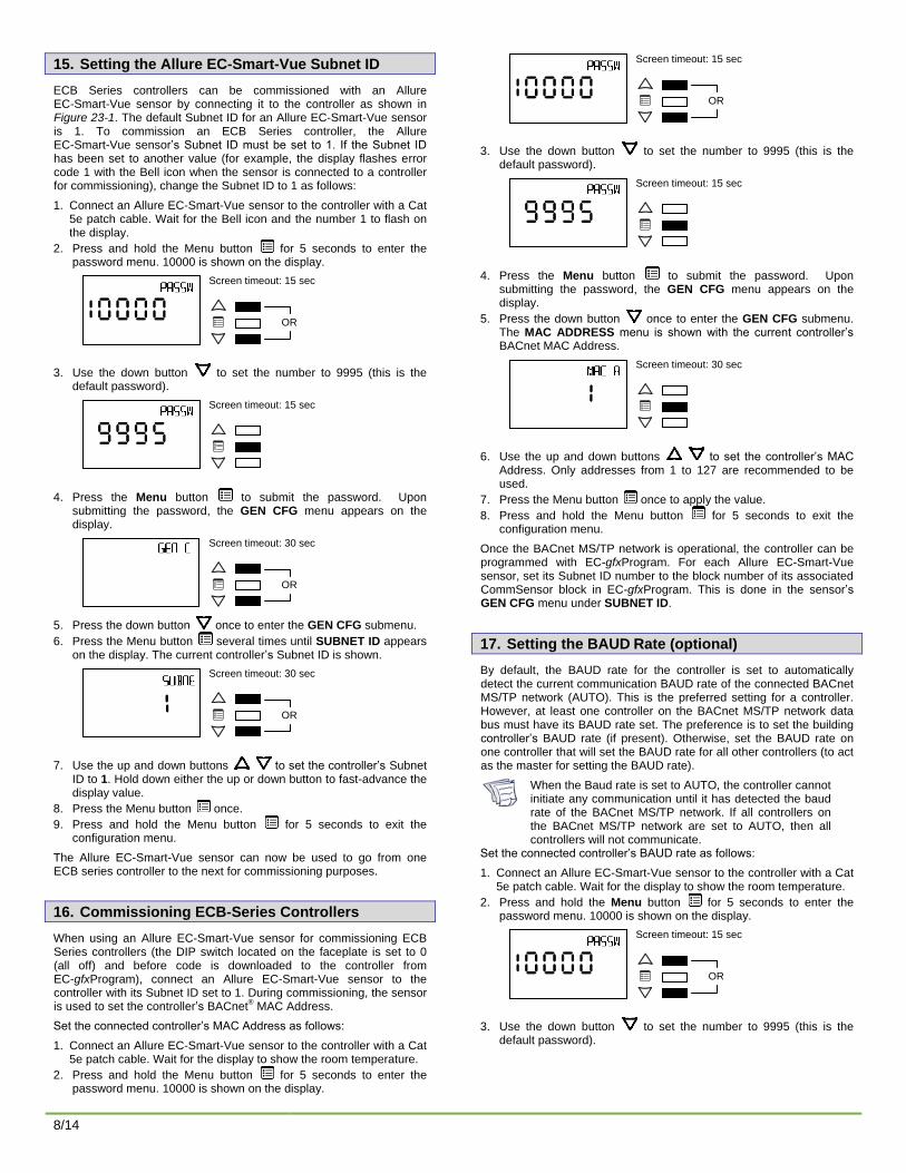
15. Setting the Allure EC-Smart-Vue Subnet ID
ECB Series controllers can be commissioned with an Allure EC-Smart-Vue sensor by connecting it to the controller as shown in Figure 23-1. The default Subnet ID for an Allure EC-Smart-Vue sensor is 1. To commission an ECB Series controller, the Allure EC-Smart-Vue sensor’s Subnet ID must be set to 1. If the Subnet ID has been set to another value (for example, the display flashes error code 1 with the Bell icon when the sensor is connected to a controller for commissioning), change the Subnet ID to 1 as follows:
1. Connect an Allure EC-Smart-Vue sensor to the controller with a Cat 5e patch cable. Wait for the Bell icon and the number 1 to flash on the display.
2. Press and hold the Menu button for 5 seconds to enter the password menu. 10000 is shown on the display.
Screen timeout: 15 sec
OR
3. Use the down button to set the number to 9995 (this is the default password).
Screen timeout: 15 sec
4. Press the Menu button to submit the password. Upon submitting the password, the GEN CFG menu appears on the display.
Screen timeout: 30 sec
OR
5. Press the down button once to enter the GEN CFG submenu.
6. Press the Menu button several times until SUBNET ID appears on the display. The current controller’s Subnet ID is shown.
Screen timeout: 30 sec
OR
7. Use the up and down buttons to set the controller’s Subnet ID to 1. Hold down either the up or down button to fast-advance the display value.
8. Press the Menu button once.
9. Press and hold the Menu button for 5 seconds to exit the configuration menu.
The Allure EC-Smart-Vue sensor can now be used to go from one ECB series controller to the next for commissioning purposes.
16. Commissioning ECB-Series Controllers
When using an Allure EC-Smart-Vue sensor for commissioning ECB Series controllers (the DIP switch located on the faceplate is set to 0 (all off) and before code is downloaded to the controller from EC-gfxProgram), connect an Allure EC-Smart-Vue sensor to the controller with its Subnet ID set to 1. During commissioning, the sensor is used to set the controller’s BACnet
® MAC Address.
Set the connected controller’s MAC Address as follows:
1. Connect an Allure EC-Smart-Vue sensor to the controller with a Cat 5e patch cable. Wait for the display to show the room temperature.
2. Press and hold the Menu button for 5 seconds to enter the password menu. 10000 is shown on the display.
Screen timeout: 15 sec
OR
3. Use the down button to set the number to 9995 (this is the default password).
Screen timeout: 15 sec
4. Press the Menu button to submit the password. Upon submitting the password, the GEN CFG menu appears on the display.
5. Press the down button once to enter the GEN CFG submenu. The MAC ADDRESS menu is shown with the current controller’s BACnet MAC Address.
Screen timeout: 30 sec
6. Use the up and down buttons to set the controller’s MAC Address. Only addresses from 1 to 127 are recommended to be used.
7. Press the Menu button once to apply the value.
8. Press and hold the Menu button for 5 seconds to exit the configuration menu.
Once the BACnet MS/TP network is operational, the controller can be programmed with EC-gfxProgram. For each Allure EC-Smart-Vue sensor, set its Subnet ID number to the block number of its associated CommSensor block in EC-gfxProgram. This is done in the sensor’s GEN CFG menu under SUBNET ID.
17. Setting the BAUD Rate (optional)
By default, the BAUD rate for the controller is set to automatically detect the current communication BAUD rate of the connected BACnet MS/TP network (AUTO). This is the preferred setting for a controller. However, at least one controller on the BACnet MS/TP network data bus must have its BAUD rate set. The preference is to set the building controller’s BAUD rate (if present). Otherwise, set the BAUD rate on one controller that will set the BAUD rate for all other controllers (to act as the master for setting the BAUD rate).
When the Baud rate is set to AUTO, the controller cannot initiate any communication until it has detected the baud rate of the BACnet MS/TP network. If all controllers on the BACnet MS/TP network are set to AUTO, then all controllers will not communicate.
Set the connected controller’s BAUD rate as follows:
1. Connect an Allure EC-Smart-Vue sensor to the controller with a Cat 5e patch cable. Wait for the display to show the room temperature.
2. Press and hold the Menu button for 5 seconds to enter the password menu. 10000 is shown on the display.
Screen timeout: 15 sec
OR
3. Use the down button to set the number to 9995 (this is the default password).

9/14
Screen timeout: 15 sec
4. Press the Menu button to submit the password. Upon submitting the password, the GEN CFG menu appears on the display.
Screen timeout: 30 sec
OR
5. Press the down button once to enter the GEN CFG submenu.
6. Press the Menu button several times until BAUD RATE appears on the display. The current controller’s baud rate is shown.
Screen timeout: 30 sec
7. Use the up and down buttons to set the controller’s baud rate. The AUTO setting detects and uses the current baud rate being used by the BACnet MS/TP network.
8. Press the Menu button once to apply the value.
9. Press and hold the Menu button for 5 seconds to exit the configuration menu.
18. Wireless Installation
When connected to a Wireless Receiver, controllers can receive input signals from a wide selection of wireless devices. Compatible wireless devices include temperature sensors, duct sensors, window/door contacts and light switches. These devices are easy to install, and can be mounted on a wide range of building materials.
The Wireless Receiver is available in 315MHz or 868.3MHz frequencies.
Connecting the Wireless Receiver
The Wireless Receiver is connected to the controller using a 2m (6.5ft) telephone cable with 4P4C modular connectors at both ends. Do not exceed this cable length. The Wireless Receiver’s telephone socket is located inside the device. To locate it, open the Wireless Receiver by separating its front and back plates.
Figure 18-1: Location of the Wireless Receiver’s telephone socket
Connecting to the Controller’s Wireless Port
Each controller has a Wireless Port in which one end of the Wireless Receiver’s telephone cable plugs in.
19. Strain Relief and Terminal Block Cover
In certain jurisdictions, terminal block covers are required to meet local safety regulations. Strain reliefs and terminal block covers are available for controllers housed in large enclosures and are used to relieve tension on the wiring and conceal the controllers’ wire terminals. Strain reliefs and terminal block covers are optional and are sold as peripherals.
Prior to connecting all wires, it is recommended to install the strain relief. Three screws are provided for its installation under the bottom part of the enclosure. Tie wraps can then be used to group wires together and attach them securely to the strain relief in an effort to relieve undue tension. If necessary, the terminal block cover can then be clipped on to the strain relief as shown below.
Figure 19-1: Large enclosure strain relief and terminal block cover installation
20. Maintenance
Turn off power before any kind of servicing.
Each controller requires minimal maintenance, but it is important to take note of the following:
- Clean the outside of the controller by polishing it with a soft dry cloth.
- Retighten terminal connector screws annually to ensure the wires remain securely attached.
21. Disposal
The Waste Electrical and Electronic Equipment (WEEE) Directive sets out regulations for the recycling and disposal of products. The WEEE2002/96/EG Directive applies to standalone products, for example, products that can function entirely on their own and are not a part of another system or piece of equipment.
For this reason Distech Controls products are exempt from the WEEE Directive. Nevertheless, Distech Controls products are marked with the
WEEE symbol , indicating devices are not to be thrown away in municipal waste.
Products must be disposed of at the end of their useful life according to local regulations and the WEEE Directive.

10/14
22. FCC Statement
Changes or modifications not expressly approved by Distech Controls could void the user's authority to operate the equipment.
This equipment has been tested and found to comply with the limits for a Class B digital device, pursuant to Part 15 of the FCC Rules. These limits are designed to provide reasonable protection against harmful interference in a residential installation. This equipment generates, uses and can radiate radio frequency energy and, if not installed and used in accordance with the instructions, may cause harmful interference to radio communications. However, there is no guarantee that interference will not occur in a particular installation. If this equipment does cause harmful interference to radio or television reception, which can be determined by turning the equipment off and on, the user is encouraged to try to correct the interference by one or more of the following measures:
- Reorient or relocate the receiving antenna.
- Increase the separation between the equipment and receiver.
- Connect the equipment into an outlet on a circuit different from that to which the receiver is connected.
- Consult the dealer or an experienced radio/TV technician for help.

11/14
23. Typical Roof Top Application Wiring Diagram
Figure 23-1: Typical Power and Network Connections with an Allure EC-Smart-Vue sensor
CoolHeat
Re
turn
Air T
em
pe
ratu
re
10kΩ
typ
e II
Su
pp
ly A
ir T
em
pe
ratu
re
10kΩ
typ
e II
Mix
ed
Air T
em
pe
ratu
re
10kΩ
typ
e II
Su
pp
ly A
ir H
um
idity
2-w
ire, 4
-20
mA
Su
pp
ly F
an
Sta
te
Dig
ita
l co
nta
ct
Re
turn
Fa
n S
tate
Dig
ita
l co
nta
ct
Damper
Re
turn
Air H
um
idity
2-w
ire, 4
-20
mA
CT CT
0-10
VDC ~+ - 0-10
VDC ~+ -
Humidifier
A2
A1
A2
A1
To
Supply
Fan
Starter
To
Return
Fan
Starter
0-10
VDC ~+ - 0-10
VDC ~+ -
Transformer
24VAC
Fuse: 4A Max.
Fast Acting
Electrical
System
Ground
Data Bus Shields: Twist together
and Isolate with electrical tape
Fro
m P
revio
us D
evic
e
To
Ne
xt D
evic
e
BA
Cn
et M
S/T
P N
etw
ork
ECB-400
*
* 249 ohm resistor built-in for inputs configured as 0-20mA
Allure EC-Smart-Vue
EOL Enabled at
the last sensor
at the end of
the Bus
ON EO
L
OFF
Back of an Allure
EC-Smart-Vue

12/14
24. Troubleshooting Guide
Controller is powered but does not turn on Fuse has blown Disconnect power from the controller. Check the fuse integrity. Reconnect power to the controller.
Power supply polarity Verify that consistent polarity is maintained between all controllers and the transformer. Ensure that the 24VCOM terminal of each controller is connected to the same terminal on the secondary side of the transformer. See Figure 6-1 and Figure 6-2.
Controller cannot communicate on an BACnet MS/TP network Absent or incorrect supply voltage 1. Check power supply voltage between 24VAC ±15% and 24VCOM pins and ensure that it is within acceptable limits.
2. Check for tripped fuse or circuit breaker.
Overloaded power transformer Verify that the transformer used is powerful enough to supply all controllers. See Power Wiring.
Network not wired properly Double check that the wire connections are correct.
Absent or incorrect network termination Check the network termination(s).
Max Master parameter Configure the maximum number of master device on the MS/TP network in all devices to the controller’s highest MAC address used on the MS/TP trunk.
There is another controller with the same MAC Address on the BACnet MS/TP data bus
Each controller on a BACnet MS/TP data bus must have a unique MAC Address. Look at the MAC Address DIP switch on the faceplate of each controller. If it is set to 0 (all off), use an Allure EC-Smart-Vue sensor to check the MAC Address.
There is another controller with the same Device ID on the BACnet intranetwork
Each controller on a BACnet intranetwork (the entire BACnet BAS network) must have a unique Device ID. Use an Allure EC-Smart-Vue sensor to check the Device ID of each controller.
Controller communicates well over a short network, but does not communicate on large network
Network length Check that the total wire length does not exceed the specifications of the Network Guide.
Wire type Check that the wire type agrees with the specification of the Network Guide.
Network wiring problem Double check that the wire connections are correct.
Absent or incorrect network termination Check the network termination(s). Incorrect or broken termination(s) will make the communication integrity dependent upon a controller’s position on the network.
Number of controllers on network segment exceeded
The number of controllers on a channel should never exceed 50. Use a router or a repeater in accordance to the Network Guide.
Max Master parameter Configure the maximum number of master device on the MS/TP network in all devices to the controller’s highest MAC address used on the MS/TP trunk.
IO Extension Module cannot communicate on the subnetwork Absent or incorrect supply voltage 1. Check power supply voltage between 24VAC ±15% and COM pins and ensure that it is within acceptable limits.
2. Check for tripped fuse or circuit breaker.
Overloaded power transformer Verify that the transformer used is powerful enough to supply all controllers. See Power Wiring.
Network not wired properly Double check that the wire connections are correct.
Absent or incorrect network termination Check the subnetwork termination(s). Only the last ECx-400 Series IO Extension module must have its EOL termination set to ON. When one or more Allure EC-Smart-Vue sensors are connected to the controller, only the last Allure EC-Smart-Vue sensor must have its EOL termination set to ON. See the Hardware Installation Guide supplied with either the ECx-400 Series IO Extension Module or Allure EC-Smart-Vue sensor.
There is another controller with the same Subnet ID on the subnetwork
Each IO Extension Module on the subnetwork must have a unique Subnet ID. Look at the Subnet ID DIP switch on the faceplate of each IO Extension Module.
Network length Check that the total wire length does not exceed the specifications of the Network Guide.
Wire type Check that the wire type agrees with the specification of the Network Guide.
Hardware input is not reading the correct value
Input wiring problem Check that the wiring is correct according to this manual and according to the peripheral device’s manufacturer.
Open circuit or short circuit Using a voltmeter, check the voltage on the input terminal. Short circuit (0V) and open circuit (5V).
Configuration problem Using the controller configuration wizard, check the configuration of the input. Refer to the controller’s user guide for more information.
Over-voltage or over-current at an input An over-voltage or over-current at one input can affect the reading of other inputs. Respect the allowed voltage / current range limits of all inputs. Consult the appropriate datasheet for the input range limits of this controller.
Hardware output is not operating correctly Fuse has blown (Auto reset fuse) Disconnect the power and outputs terminals. Then wait a few seconds to allow the auto-reset fuse to cool down. Check
the power supply and the output wiring. Reconnect the power.
Output wiring problem Check that the wiring is correct according to this manual and according to the peripheral device’s manufacturer.
Configuration problem Using the controller configuration wizard, check the configuration of the output. Refer to the controller’s programming user guide for more information.
0 to 10V output, 24VAC powered actuator is not moving.
Check the polarity of the 24VAC power supply connected to the actuator while connected to the controller. Reverse the 24VAC wire if necessary.
Wireless devices not working correctly Device not associated to controller Using the device configuration wizard, check the configuration of the input. Refer to the device’s user guide for more
information.
Power discharge 1. Recharge device with light (if solar-powered) or replace battery (if battery-powered), 2. Ensure sufficient light intensity (200lx for 4 hours/day).
Device too far from the Wireless Receiver Reposition the device to be within the range of the Wireless Receiver. For information on typical transmission ranges, refer to the Open-to-Wireless Solution Guide.
Configuration problem Using the device configuration plug-in or wizard, check the configuration of the input. Refer to the Wireless Battery-less Sensors and Switches Solutions Guide for more information.
Rx/Tx LEDs RX LED not blinking Data is not being received from the BACnet MS/TP data bus.
TX LED not blinking Data is not being transmitted onto the BACnet MS/TP data bus.

13/14
For issues with the Allure EC-Smart-Vue sensor, refer to the Allure EC-Smart-Vue Hardware Installation Guide. For issues with the ECx-400 Series IO Extension Module, refer to the ECx-400 Series IO Extension Module Hardware Installation Guide.
Status LED– Normal Operation One fast blink
Initialization: The device is starting up.
Fast blink continuous:
(150ms On, 150ms Off, continuous)
Firmware upgrade in progress. Controller operation is temporarily unavailable. The new firmware is being loaded into memory. This takes a few seconds. Do not interrupt power to the device during this time.
The Status LED is always OFF The controller is operating normally.
Status LED blink patterns – Repeats every 2 seconds (highest priority shown first) Long Long Long blink
(800ms On, 300ms Off, 800ms On, 300ms Off, 800ms On)
The device has not received a BACnet token, and therefore cannot communicate on the network: Verify that the controller’s MAC Address is unique on the BACnet MS/TP Data Bus – see Section 12. Make sure the controller’s BAUD rate is the same as the BACnet MS/TP Data Bus’ BAUD rate (see Section 17). Verify that the Max Master is set high enough to include this controller’s MAC Address (See the Network Guide).
Short Short Long blink
(150ms On, 300ms Off, 150ms On, 300ms Off, 800 ms On)
Poor-quality power; The device has browned-out: The voltage at the 24VAC and 24VCOM terminals has gone below the device’s acceptable limit during power up.
Short Long blink
(150ms On, 300ms Off)
Invalid MAC address: The device’s MAC address is set to zero (0) or is set to an address higher than the Max Master. See the Network Guide .
Long Short Short Short Short Long Short:
(800ms On, 300ms Off, 150ms On, 300ms Off, 150ms On, 300ms Off, 150ms On, 300ms Off, 150ms On, 300ms Off, 800ms On, 300ms Off, 150ms On)
Backup and Restore. The controller is being backed-up or restored.
Total Quality Commitment
All Distech Controls product lines are built to meet rigorous quality standards. Distech Controls is an ISO 9001 registered company.
Hardware Installation Guide: ECB-203, ECB-300, ECB-400, and ECB-600 Series
©, Distech Controls Inc., 2010. All rights reserved.
Images are simulated. While all efforts have been made to verify the accuracy of information in this manual, Distech Controls is not responsible for damages or claims arising from the use of this manual. Persons using this manual are assumed to be trained HVAC specialist / installers and are responsible for using the correct wiring procedures and maintaining safe working conditions with fail-safe environments. Distech Controls reserves the right to change, delete or add to the information in this
manual at any time without notice.
Distech Controls, the Distech Controls logo, Open-to-Wireless, Innovative Solutions for Greener Buildings, and Allure are trademarks of Distech Controls Inc. BACnet is a registered trademark of ASHRAE. NiagaraAX Framework is a registered trademark of Tridium, Inc.
14/14 *05DI-HIECBXX-17* 05DI-HIECBXX-17