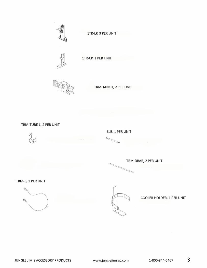
hardware qty part # description · hardware qty part # description 44 104 3/8” – 16 x ¾”...
TRANSCRIPT

HARDWARE
QTY PART # DESCRIPTION 44 104 3/8” – 16 x ¾” Carriage Bolt Zinc
60 315 3/8” – 16 Hex Flange Nut 16 414 3/8” – 16 Split Ring Lock Washer YZ 4 109 3/8” – 16 x 2 ¾” Carriage Bolt Z
14 407 3/8” USS Flat Washer YZ
4 107 3/8” – 16 x 1 ¾” Carriage Bolt Z 8 200 3/8” – 16 x ½” Hex Cap Screw YZ 4 412 5/16” Split Ring Lock Washer YZ
4 213 5/16” – 18 x ¾” Hex Cap Screw YZ 1 806 Hit Pin Clip 16 Z 2 402 ½” Flat Washer YZ 1 GC—SLB HOSE 5/8”I.D. x 2” L. Hose
1 Cool-Hard Cooler Hardware 1 303 3/8” – 16 Nylon Lock Nut YZ 3 ATR-WASH 3/8” Square Washer YZ 3 101 5/16” – 18 x 5/8” Flange Bolt Z
3 711 ½” x 1” Hose 3 ATR-CP Trimmer Rack Compression Pin YZ 3 206 3/8” – 16 x 2” FHSCS Z
3 ATR-LN TR Locking Nut 36 104 3/8” – 16 x ¾” Carriage Bolt Z 52 315 3/8” – 16 Hex Flange Nut YZ
***For missing hardware or product questions, please contact Jungle Jim’s.***

JUNGLE JIM’S ACCESSORY PRODUCTS www.junglejimsap.com 1-800-844-5467 2
JUNGLE JIM’S ACCESSORY PRODUCTS www.junglejimsap.com 1-800-844-5467 3

JUNGLE JIM’S ACCESSORY PRODUCTS www.junglejimsap.com 1-800-844-5467 4
ASSEMBLY
ASSEMBLE THE BASKET
1 For this step you will need a 9/16” wrench or socket and the following parts:
QTY PART DESCRIPTION
16 104 3/8” – 16 x ¾” Carriage Bolt YZ
16 315 3/8” – 16 Flange Nut YZ
16 414 3/8” Split Lock Washer YZ
1 TRM-BOTTOM
2 TRM-SIDE
2 TRM-END
2 Attach both of the TRM-SIDES to the TRM-BOTTOM. The sides mount under the edge of the bottom as shown
in the figure above. There are four holes on the long sides of the TRM-BOTTOM. Insert part # 104 through
both the TRM-SIDE & TRM-BOTTOM. Note direction of the bolts in the figure above. Do NOT fully tighten the
bolts until after the legs are attached in a later step.
3 Attach both TRM-ENDS. Note that the TRM-END is mounted to the inside of the TRM-SIDES and under the
edge of the TRM-BOTTOM. There is one hole for mounting to the TRM-END to the TRM-SIDE and two holes
for mounting the TRM-END to the TRM-BOTTOM.
***WAIT TO FULLY TIGHTEN BOLTS UNTIL THE BASKET IS FULLY ASSEMBLED AND ON THE TRAILER***

JUNGLE JIM’S ACCESSORY PRODUCTS www.junglejimsap.com 1-800-844-5467 5
ATTACH THE BLOWERPOSTS
1 For this step, you will need a 9/16” wrench or socket and the following parts:
QTY PART DESCRIPTION
2 TRM-BLOWER
2 TRM-BLOWERPOST1
2 TRM-BHOOK1
4 109 3/8” – 16 x 2 ¾” Carriage Bolt YZ
4 407 3/8” USS Flat Washer YZ
4 315 3/8” – 16 Hex Flange Nut Z
4 107 3/8” – 16 x 1 ¾” Carriage Bolt Z
2 Attach a TRM-BLOWER & TRM-BLOWERPOST1 to each TRM-END using two 109’s, two 407’s, and two 315’s.
3 Attach the TRM-BHOOK1 to the TRM-BLOWERPOST1 using two 107’s, two 407’s, and two 315’s.
4 Adjust the TRM-BLOWERPOST1 to make sure the blower sits above the legs.
****The hole on the end of the TRM-BHOOK1 can be used in conjunction with a lock for added security.****

JUNGLE JIM’S ACCESSORY PRODUCTS www.junglejimsap.com 1-800-844-5467 6
ASSEMBLE THE LEGS
For this step, you will need a 9/16” wrench or socket and the following parts:
QTY PART DESCRIPTION
8 104 3/8” – 16 x ¾” Carriage Bolt YZ
8 414 3/8” Split Lock Washer YZ
8 315 3/8” – 16 Flange Nut YZ
1 TRM-SLEGRW
1 TRM-SLEGLW
2 TRM-SLEGMAIN
4 TRM-ALEG2
1 The above picture shows correct placement of parts.
2 Tighten all bolts.
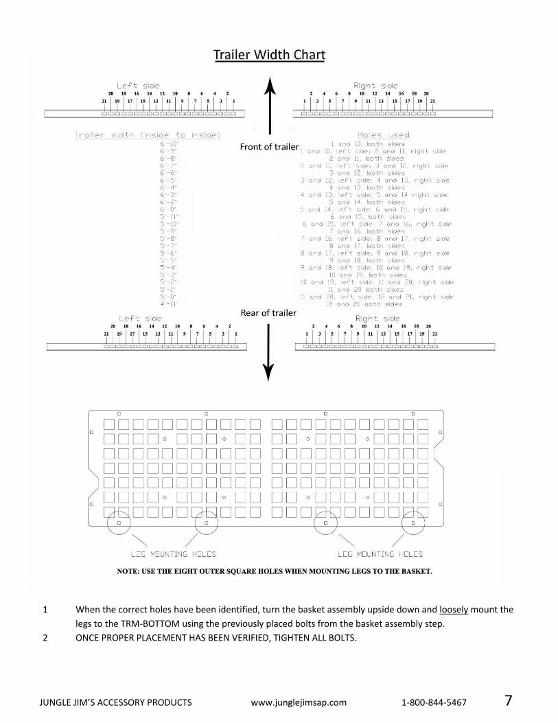
3 Once the legs are assembled, use the following chart for mounting the basket on the legs. The width of your
trailer will determine which holes you use on the TRM-ALEGS to mount your basket onto the trailer.
JUNGLE JIM’S ACCESSORY PRODUCTS www.junglejimsap.com 1-800-844-5467 7
1 When the correct holes have been identified, turn the basket assembly upside down and loosely mount the
legs to the TRM-BOTTOM using the previously placed bolts from the basket assembly step.
2 ONCE PROPER PLACEMENT HAS BEEN VERIFIED, TIGHTEN ALL BOLTS.

JUNGLE JIM’S ACCESSORY PRODUCTS www.junglejimsap.com 1-800-844-5467 8
MOUNT BASKET ASSEMBLY ON TRAILER
1 For this step, you will need assistance in placing the basket on the trailer rails.
2 Once the desired location (of the legs) has been determined, mark the rails and remove the basket from
trailer.
3 Using a 3/8” or larger drill bit, drill holes in the trailer rails. Bolts included with the product are long enough
for .250 angle iron frames. Square or round tube rails will require longer bolts that can be purchased at a
hardware store.
4 Replace basket assembly and secure to the rails using eight 104’s and eight 315’s.
5 Align both 1TR-LP on each side of the trailer to ensure proper trimmer position. Mark rails and drill holes
using the same drill bit. Using four 104’s and four 315’s, secure both 1TR-LP to the trailer rails.
6 Repeat for the front mounted 1TR-LP and 1TR-CP.
ADJUSTMENT
TOOLS REQUIRED: ½” socket wrench with extension or ½” deep socket.
1 Place the trimmer in the rack by putting the cutting end of the shaft into the hook on the compression pole.
Lift the engine end of the trimmer up and into the hook on the locking pole. The trimmer should be
positioned so that the handle is resting in the hook on the engine end. Be careful not to damage the throttle
trigger when placing the trimmer into the rack.
2 In order to prevent the trimmer from rotating while in the rack, the compression pin must be adjusted
properly. Slide the compression pin down until it is touching the trimmer shaft and tighten the bolt. Remove
the trimmer and slide the compression pin down another 1/8” lower and fully tighten the bolt on the
compression pin.
3 Place the trimmer in the rack and test to make sure the trimmer doesn’t rotate easily. If it does, remove the
trimmer and re-adjust the compression pin down in 1/16” increments until the rack holds the trimmer firmly,
but not so tightly that the trimmer cannot be removed.
JUNGLE JIM’S ACCESSORY PRODUCTS www.junglejimsap.com 1-800-844-5467 9
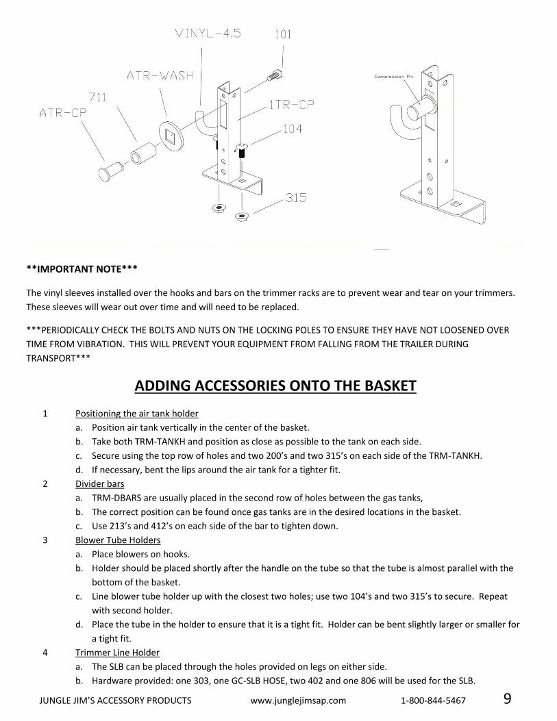
**IMPORTANT NOTE***
The vinyl sleeves installed over the hooks and bars on the trimmer racks are to prevent wear and tear on your trimmers.
These sleeves will wear out over time and will need to be replaced.
***PERIODICALLY CHECK THE BOLTS AND NUTS ON THE LOCKING POLES TO ENSURE THEY HAVE NOT LOOSENED OVER
TIME FROM VIBRATION. THIS WILL PREVENT YOUR EQUIPMENT FROM FALLING FROM THE TRAILER DURING
TRANSPORT***
ADDING ACCESSORIES ONTO THE BASKET
1 Positioning the air tank holder
a. Position air tank vertically in the center of the basket.
b. Take both TRM-TANKH and position as close as possible to the tank on each side.
c. Secure using the top row of holes and two 200’s and two 315’s on each side of the TRM-TANKH.
d. If necessary, bent the lips around the air tank for a tighter fit.
2 Divider bars
a. TRM-DBARS are usually placed in the second row of holes between the gas tanks,
b. The correct position can be found once gas tanks are in the desired locations in the basket.
c. Use 213’s and 412’s on each side of the bar to tighten down.
3 Blower Tube Holders
a. Place blowers on hooks.
b. Holder should be placed shortly after the handle on the tube so that the tube is almost parallel with the
bottom of the basket.
c. Line blower tube holder up with the closest two holes; use two 104’s and two 315’s to secure. Repeat
with second holder.
d. Place the tube in the holder to ensure that it is a tight fit. Holder can be bent slightly larger or smaller for
a tight fit.
4 Trimmer Line Holder
a. The SLB can be placed through the holes provided on legs on either side.
b. Hardware provided: one 303, one GC-SLB HOSE, two 402 and one 806 will be used for the SLB.
JUNGLE JIM’S ACCESSORY PRODUCTS www.junglejimsap.com 1-800-844-5467 10
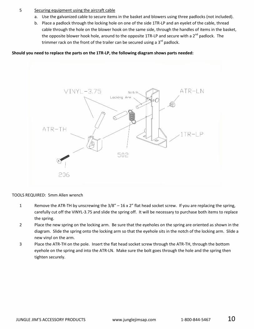
5 Securing equipment using the aircraft cable
a. Use the galvanized cable to secure items in the basket and blowers using three padlocks (not included).
b. Place a padlock through the locking hole on one of the side 1TR-LP and an eyelet of the cable, thread
cable through the hole on the blower hook on the same side, through the handles of items in the basket,
the opposite blower hook hole, around to the opposite 1TR-LP and secure with a 2nd padlock. The
trimmer rack on the front of the trailer can be secured using a 3rd padlock.
Should you need to replace the parts on the 1TR-LP, the following diagram shows parts needed:
TOOLS REQUIRED: 5mm Allen wrench
1 Remove the ATR-TH by unscrewing the 3/8” – 16 x 2” flat head socket screw. If you are replacing the spring,
carefully cut off the VINYL-3.75 and slide the spring off. It will be necessary to purchase both items to replace
the spring.
2 Place the new spring on the locking arm. Be sure that the eyeholes on the spring are oriented as shown in the
diagram. Slide the spring onto the locking arm so that the eyehole sits in the notch of the locking arm. Slide a
new vinyl on the arm.
3 Place the ATR-TH on the pole. Insert the flat head socket screw through the ATR-TH, through the bottom
eyehole on the spring and into the ATR-LN. Make sure the bolt goes through the hole and the spring then
tighten securely.

JUNGLE JIM’S ACCESSORY PRODUCTS www.junglejimsap.com 1-800-844-5467 11
COOLER HOLDER INSTRUCTIONS
For this step, you will need the following parts:
QTY PART # DESCRIPTION 1 each 705 Male & Female Buckles
2 703 Tri-glide fasteners
2 717 30” straps
1 COOL-CHB Cooler Holder Bracket
1 COOL-CB Cooler Base
2 201 3/8” – -16 X 5/8” Round M/S Z
2 313 3/8” – 16 Lock Jam Nut
2 203 3/8” – 16 x 1” HCS GR5 Z
2 307 3/8” -16 Hex Flange Nut
2 416 3/8” Split Lock Washer Z
1 Mount Cooler Holder Bracket (COOL-CHB) on the Cooler Base (COOL-CB) using two each of parts # 313 and
201.
2 Determine placement for the cooler assembly on the trailer and mark holes on trailer.
3 Drill holes through rail and mount cooler assembly to trailer using two each of parts # 203, 307 and 416
4 Insert one 30” strap through the right side of cooler holder bracket.
5 Pull strap so that both sides are even.
6 Insert only the right side of the strap through the right side of one of tri-glide fastener.
7 Follow the same strap over and through the same tri-glide.
8 Slide the tri-glide to the center of the strap.
9 Insert both ends of the strap through the left slot of the male buckle.
10 Insert both ends of the strap over and through the right slot of the male buckle.
11 Insert both ends of the strap up and through the left side of the tri-glide.
JUNGLE JIM’S ACCESSORY PRODUCTS www.junglejimsap.com 1-800-844-5467 12
12 Insert both ends of the strap over and through the right side of the tri-glide. Right side is now complete.
13 Repeat steps 4 – 12 using the female buckle, second strap and second tri-glide.
14 Insert cooler on base and buckle straps.
15 Adjust strap size using tri-glide fasteners so that the cooler is held securely in the holder.
MOUNTING THE OPTIONAL TOOL RACK (TRM-TR)
QTY PART # DESCRIPTION
1 TR-TOP Top rail of Tool Rack 1 TR-BOTTOM Bottom Rail of Tool Rack
2 TRM-BLOWERPOST Posts for mounting onto Basket
8 203 3/8"-16 x 1 HCS GR5 Z 2 109 3/8"-16 X 2 ¾" Carriage Bolt Z
12 307 3/8"-16 Hex Flange Nut Z 4 407 3/8” USS Flat Washer
5 800 Tool Rack Grommet 2 209 3/8"-16 X 2 ¾" HCS GR5 Z
ASSEMBLY
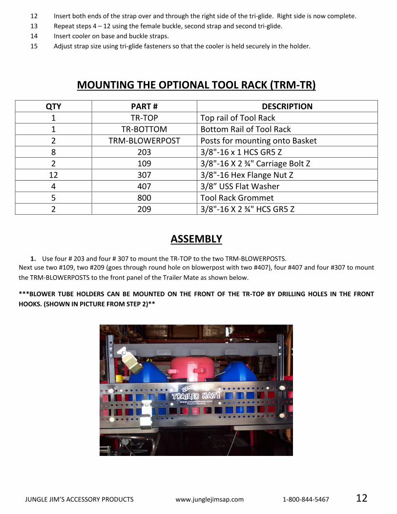
1. Use four # 203 and four # 307 to mount the TR-TOP to the two TRM-BLOWERPOSTS. Next use two #109, two #209 (goes through round hole on blowerpost with two #407), four #407 and four #307 to mount
the TRM-BLOWERPOSTS to the front panel of the Trailer Mate as shown below.
***BLOWER TUBE HOLDERS CAN BE MOUNTED ON THE FRONT OF THE TR-TOP BY DRILLING HOLES IN THE FRONT
HOOKS. (SHOWN IN PICTURE FROM STEP 2)**

JUNGLE JIM’S ACCESSORY PRODUCTS www.junglejimsap.com 1-800-844-5467 13
2. Mount the TR-BOTTOM using the remaining 4- #203 and 4- #307’s to the inside of the front rail of the trailer as shown below.
LIMITED WARRANTY
Seller (Jungle Jim’s Accessory Products, Inc.) warrants that the Trailer Mate product (device) will comply with applicable
laws governing the operation of such a device. Seller further warrants that the device will be free from defects in material
and workmanship for a period of one year from the date that the device is purchased. During the stated one year period,
seller will supply replacements for parts found to be defective free of charge to the purchaser. Any parts which are not
found to be defective shall be replaced at additional cost to the purchaser. Seller shall not be required to replace any part
that has been abused or not operated in accordance with the printed instructions which were provided with the device.
After the initial one year period, seller shall have no obligations or liability to the purchaser. The warranties provided
hereunder shall not apply if the device has been subject to accident, negligence, alteration (including signs of welding)
abuse, or misuse. Seller makes no warranty whatsoever with respect to accessories or parts not supplied with it. Further,
this warranty shall apply only to the original purchaser. Original purchaser shall mean that person or entity who first
acquired the device. Seller does not warrant this device to meet the requirements of any safety code of any state,
municipality or other jurisdiction. Purchaser assumes all risk and liability whatsoever resulting from the use thereof
whether used singly or in combination with other machines or apparatus. Further, seller is not liable for replacement of
equipment secured on the device. Purchaser is responsible for ensuring that all hardware is checked periodically for
security of said equipment. THIS WARRANTY IS EXPRESSLY MADE IN LIEU OF THE WARRANTIES OF MERCHANTABILITY
AND FITNESS FOR USE AND ANY OTHER WARRANTIES EXPRESSED OR IMPLIED. THE SOLE LIABILITY OF THE WARRANTY
SHALL BE THE REPAIR AND REPLACEMENT OF PARTS, NECESSARY ADJUSTMENTS, OR OTHER REPAIRS REQUIRED TO
MAINTAIN THE DEVICE IN PROPER WORKING ORDER. THE SELLER SHALL NOT BE HELD LIABLE FOR ANY DELAYS CAUSED
BY CIRCUMSTANCES BEYOND ITS CONTROL OR BY DAMAGES CAUSED BY THE OPERATION OF THE DEVICE IN ANY MANNER
NOT IN ACCORDANCE WITH THE PRINTED INSTRUCTIONS PROVIDED WITH THE DEVICE.
Two year limited warranty is dependent upon the return of the registration form.
Mail to:
Jungle Jim’s Accessory Products, Inc., 550 O’Byrne Avenue, Louisville, KY 40223 Or fax to: 502-254-3677
Registration must be mailed within 30 days of purchase with a copy of the original receipt showing date of purchase.

JUNGLE JIM’S ACCESSORY PRODUCTS www.junglejimsap.com 1-800-844-5467 14
-----------------------------------------------------------------------------------------------------------------------------------------------------------
WARRANTY REGISTRATION – TRAILER MATE PRO
COMPANY
LAST NAME
FIRST
ADDRESS
CITY
STATE ZIP
PHONE
PLACE OF PURCHASE
CITY
STATE ZIP
COMMENTS/SUGGESTIONS: