harmonic drive servomotor chm - treffer.com.br · harmonic drive system gmbh was established in...
TRANSCRIPT
CHM – Harmonic Drive ServomotorCHM – Harmonic Drive Servo Motor
Inhalt
Das Unternehmen
The Company
Produktbeschreibung
Product Description
Bestellbezeichnungen
Ordering Code
Technische Daten
Technical Data
6 Leistungsdaten / Rating Table
8 Leistungscharakteristik / Performance Characteristics
9 Abmessungen / Dimensions
10 Montage der Last / Assembly of the Load
10 Montage des Gehäuseflansches
Assembly of the Housing Flange
3
4
5
6
2
InhaltContent
Das UnternehmenThe Company
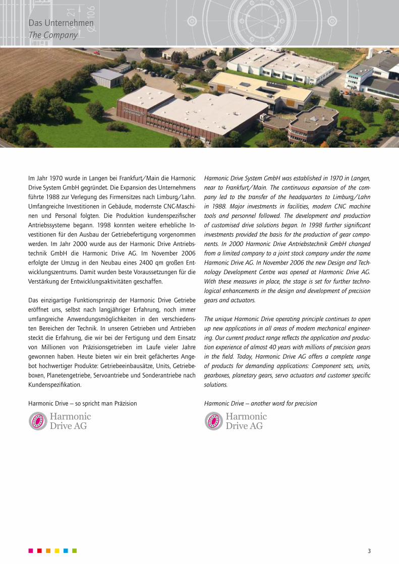
Im Jahr 1970 wurde in Langen bei Frankfurt/Main die Harmonic Drive System GmbH gegründet. Die Expansion des Unternehmens führte 1988 zur Verlegung des Firmensitzes nach Limburg/Lahn. Umfangreiche Investitionen in Gebäude, modernste CNC-Maschi-nen und Personal folgten. Die Produktion kundenspezifischer Antriebssysteme begann. 1998 konnten weitere erhebliche In-vestitionen für den Ausbau der Getriebefertigung vorgenommen werden. Im Jahr 2000 wurde aus der Harmonic Drive Antriebs-technik GmbH die Harmonic Drive AG. Im November 2006 erfolgte der Umzug in den Neubau eines 2400 qm großen Ent-wicklungszentrums. Damit wurden beste Voraussetzungen für die Verstärkung der Entwicklungsaktivitäten geschaffen.
Das einzigartige Funktionsprinzip der Harmonic Drive Getriebe eröffnet uns, selbst nach langjähriger Erfahrung, noch immer umfangreiche Anwendungsmöglichkeiten in den verschiedens-ten Bereichen der Technik. In unseren Getrieben und Antrieben steckt die Erfahrung, die wir bei der Fertigung und dem Einsatz von Millionen von Präzisionsgetrieben im Laufe vieler Jahre gewonnen haben. Heute bieten wir ein breit gefächertes Ange-bot hochwertiger Produkte: Getriebeeinbausätze, Units, Getriebe-boxen, Planetengetriebe, Servoantriebe und Sonderantriebe nach Kundenspezifikation.
Harmonic Drive – so spricht man Präzision
Harmonic Drive System GmbH was established in 1970 in Langen, near to Frankfurt/Main. The continuous expansion of the com-pany led to the transfer of the headquarters to Limburg/Lahn in 1988. Major investments in facilities, modern CNC machine tools and personnel followed. The development and production of customised drive solutions began. In 1998 further significant investments provided the basis for the production of gear compo-nents. In 2000 Harmonic Drive Antriebstechnik GmbH changed from a limited company to a joint stock company under the name Harmonic Drive AG. In November 2006 the new Design and Tech-nology Development Centre was opened at Harmonic Drive AG. With these measures in place, the stage is set for further techno-logical enhancements in the design and development of precision gears and actuators.
The unique Harmonic Drive operating principle continues to open up new applications in all areas of modern mechanical engineer-ing. Our current product range reflects the application and produc-tion experience of almost 40 years with millions of precision gears in the field. Today, Harmonic Drive AG offers a complete range of products for demanding applications: Component sets, units, gearboxes, planetary gears, servo actuators and customer specific solutions.
Harmonic Drive – another word for precision
3
Das UnternehmenThe Company
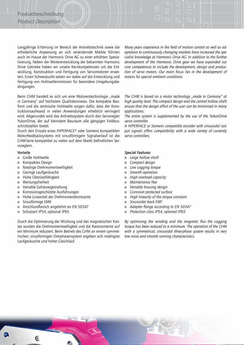
Langjährige Erfahrung im Bereich der Antriebstechnik sowie die erforderliche Anpassung an sich verändernde Märkte führten auch im Hause der Harmonic Drive AG zu einer erhöhten Spezia-lisierung. Neben der Weiterentwicklung der bekannten Harmonic Drive Getriebe haben wir unsere Kernkompetenzen um die Ent-wicklung, Konstruktion und Fertigung von Servomotoren erwei-tert. Einen Schwerpunkt setzen wir dabei auf die Entwicklung und Fertigung von Hohlwellenmotoren für besondere Umgebungsbe-dingungen.
Beim CHM handelt es sich um eine Motorentechnologie „made in Germany“ auf höchstem Qualitätsniveau. Die kompakte Bau-form und die zentrische Hohlwelle sorgen dafür, dass der Kons-truktionsaufwand in vielen Anwendungen erheblich verringert wird. Abgerundet wird das Antriebssystem durch den Servoregler YukonDrive, der auf kleinstem Bauraum alle gängigen Feldbus-schnittstellen bietet.Durch den Einsatz eines HIPERFACE® oder Siemens kompatiblen Motorfeedbacksystems mit sinusförmigem Signalverlauf ist die CHM-Serie kompatibel zu vielen auf dem Markt befindlichen Ser-voreglern.
Many years experience in the field of motion control as well as ad-aptation to continuously changing markets have increased the spe-cialist knowledge at Harmonic Drive AG. In addition to the further development of the Harmonic Drive gear we have expanded our core competences to include the development, design and produc-tion of servo motors. Our main focus lies in the development of motors for special ambient conditions.
The CHM is based on a motor technology „made in Germany“ at high quality level. The compact design and the central hollow shaft ensure that the design effort of the user can be minimised in many applications.The entire system is supplemented by the use of the YukonDrive servo controller.A HIPERFACE or Siemens compatible encoder with sinusoidal out-put signals offers compatibility with a wide variety of currently servo controllers.
Vorteile Große Hohlwelle Kompaktes Design Niedrige Drehmomentwelligkeit Geringe Laufgeräusche Hohe Überlastfähigkeit Wartungsfreiheit Variable Gehäusegestaltung Korrosionsgeschützte Ausführungen Hohe Linearität der Drehmomentkonstante Sinusförmige EMK Anschlussflansch angelehnt an EN 50347 Schutzart IP54, optional IP65
Durch die Optimierung der Wicklung und des magnetischen Krei-ses wurden die Drehmomentwelligkeit und die Rastmomente auf ein Minimum reduziert. Beim Betrieb des CHM an einem symmet-rischen, sinusförmigen Dreiphasensystem ergeben sich niedrigste Laufgeräusche und hoher Gleichlauf.
Special Features Large hollow shaft Compact design Low cogging torque Smooth operation High overload capacity Maintenance free Variable housing design Corrosion protected surface High linearity of the torque constant Sinusoidal back EMF Adapter flange according to EN 50347 Protection class IP54, optional IP65
By optimising the winding and the magnetic flux the cogging torque has been reduced to a minimum. The operation of the CHM with a symmetrical, sinusoidal three-phase system results in very low noise and smooth running characteristics.
4
ProduktbeschreibungProduct Description
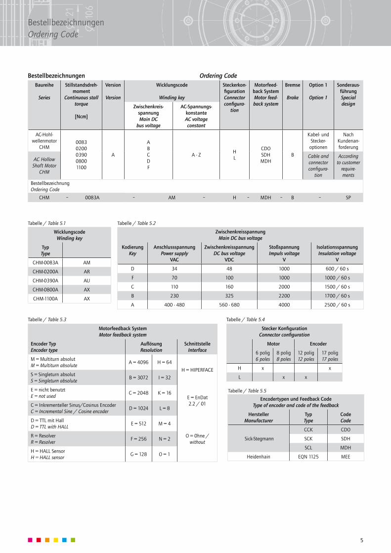
Bestellbezeichnungen Ordering Code
Zwischenkreisspannung Main DC bus voltage
Kodierung Key
Anschlussspannung Power supply
VAC
Zwischenkreisspannung DC bus voltage
VDC
Stoßspannung Impuls voltage
V
Isolationsspannung Insulation voltage
V
D 34 48 1000 600 / 60 s
F 70 100 1000 1000 / 60 s
C 110 160 2000 1500 / 60 s
B 230 325 2200 1700 / 60 s
A 400 - 480 560 - 680 4000 2500 / 60 s
Tabelle / Table 5.1 Tabelle / Table 5.2
Tabelle / Table 5.4Tabelle / Table 5.3
Tabelle / Table 5.5
Stecker KonfigurationConnector configuration
Motor Encoder
6 polig6 poles
8 polig8 poles
12 polig12 poles
17 polig17 poles
H x x
L x x
Motorfeedback System Motor feedback system
Encoder Typ Encoder type
Auflösung Resolution
Schnittstelle Interface
M = Multiturn absolut M = Multiturn absolute
A = 4096 H = 64
H = HIPERFACES = Singleturn absolut S = Singleturn absolute
B = 3072 I = 32
E = nicht benutzt E = not used
C = 2048 K = 16E = EnDat 2.2 / 01C = Inkrementeller Sinus/Cosinus Encoder
C = Incremental Sine / Cosine encoderD = 1024 L = 8
D = TTL mit Hall D = TTL with HALL
E = 512 M = 4
O = 0hne / without
R = Resolver R = Resolver
F = 256 N = 2
H = HALL Sensor H = HALL sensor
G = 128 O = 1
Encodertypen und Feedback Code Type of encoder and code of the feedback
Hersteller Manufacturer
Typ Type
Code Code
Sick-Stegmann
CCK CDO
SCK SDH
SCL MDH
Heidenhain EQN 1125 MEE
Wicklungscode Winding key
Typ Type
CHM-0083A AM
CHM-0200A AR
CHM-0390A AU
CHM-0800A AX
CHM-1100A AX
Baureihe
Series
Stillstandsdreh-moment
Continuous stall torque
[Ncm]
Version
Version
Wicklungscode
Winding key
Steckerkon-figuration Connector configura-
tion
Motorfeed-back System Motor feed-back system
Bremse
Brake
Option 1
Option 1
Sonderaus-führung Special designZwischenkreis-
spannung Main DC
bus voltage
AC-Spannungs-konstante AC voltage constant
AC-Hohl-wellenmotor
CHM0083 0200 0390 0800 1100
A
A B C D F
A - ZH L
CDO SDH MDH
B
Kabel- und Stecker-
optionen
Nach Kundenan-forderung
AC Hollow Shaft Motor
CHM
Cable and connector configura-
tion
According to customer
require-ments
Bestellbezeichnung Ordering Code
CHM 0083A AM H MDH B SP– – – – – –
5
BestellbezeichnungenOrdering Code
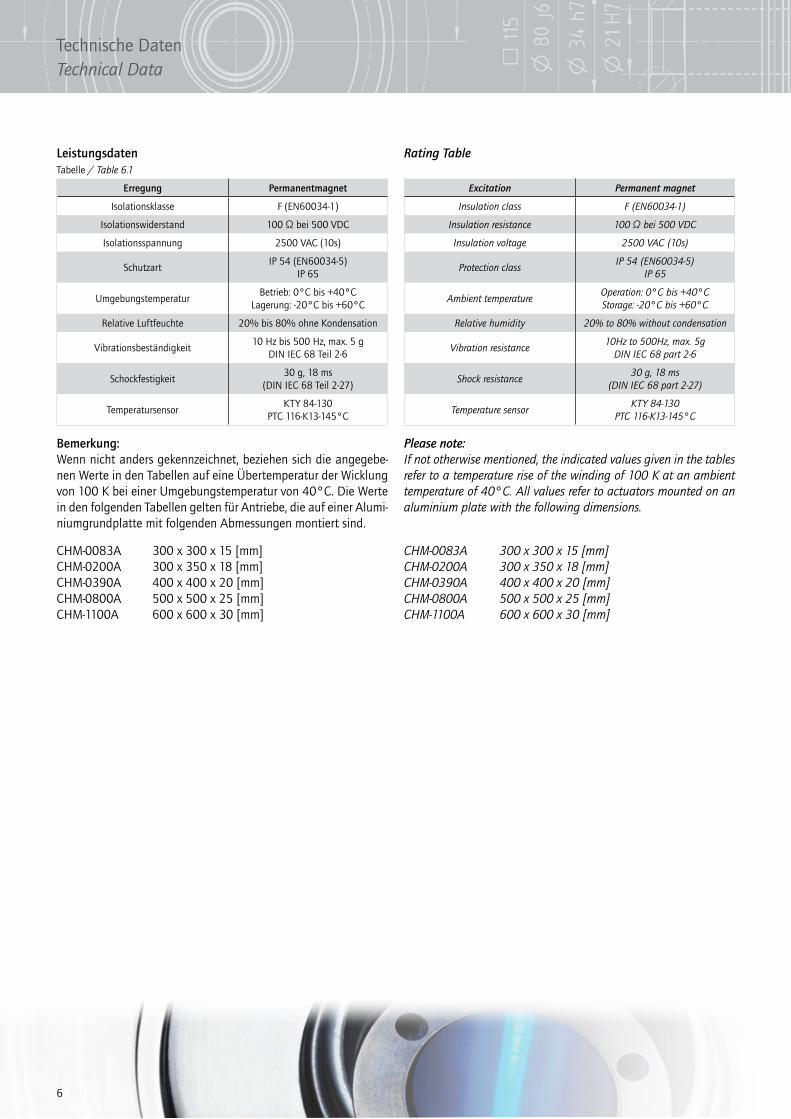
Leistungsdaten Rating TableTabelle / Table 6.1
Erregung Permanentmagnet
Isolationsklasse F (EN60034-1)
Isolationswiderstand 100 Ω bei 500 VDC
Isolationsspannung 2500 VAC (10s)
SchutzartIP 54 (EN60034-5)
IP 65
UmgebungstemperaturBetrieb: 0°C bis +40°C
Lagerung: -20°C bis +60°C
Relative Luftfeuchte 20% bis 80% ohne Kondensation
Vibrationsbeständigkeit10 Hz bis 500 Hz, max. 5 g
DIN IEC 68 Teil 2-6
Schockfestigkeit30 g, 18 ms
(DIN IEC 68 Teil 2-27)
TemperatursensorKTY 84-130
PTC 116-K13-145°C
Excitation Permanent magnet
Insulation class F (EN60034-1)
Insulation resistance 100 Ω bei 500 VDC
Insulation voltage 2500 VAC (10s)
Protection classIP 54 (EN60034-5)
IP 65
Ambient temperatureOperation: 0°C bis +40°C Storage: -20°C bis +60°C
Relative humidity 20% to 80% without condensation
Vibration resistance10Hz to 500Hz, max. 5g
DIN IEC 68 part 2-6
Shock resistance30 g, 18 ms
(DIN IEC 68 part 2-27)
Temperature sensorKTY 84-130
PTC 116-K13-145°C
Bemerkung:Wenn nicht anders gekennzeichnet, beziehen sich die angegebe-nen Werte in den Tabellen auf eine Übertemperatur der Wicklung von 100 K bei einer Umgebungstemperatur von 40°C. Die Werte in den folgenden Tabellen gelten für Antriebe, die auf einer Alumi-niumgrundplatte mit folgenden Abmessungen montiert sind.
Please note:If not otherwise mentioned, the indicated values given in the tables refer to a temperature rise of the winding of 100 K at an ambient temperature of 40°C. All values refer to actuators mounted on an aluminium plate with the following dimensions.
CHM-0083A 300 x 300 x 15 [mm]CHM-0200A 300 x 350 x 18 [mm]CHM-0390A 400 x 400 x 20 [mm]CHM-0800A 500 x 500 x 25 [mm]CHM-1100A 600 x 600 x 30 [mm]
CHM-0083A 300 x 300 x 15 [mm]CHM-0200A 300 x 350 x 18 [mm]CHM-0390A 400 x 400 x 20 [mm]CHM-0800A 500 x 500 x 25 [mm]CHM-1100A 600 x 600 x 30 [mm]
6
Technische DatenTechnical Data
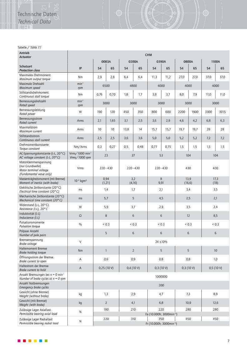
Tabelle / Table 7.1
Antrieb Actuator
CHM
0083A 0200A 0390A 0800A 1100ASchutzart Protection class
IP 54 65 54 65 54 65 54 65 54 65
Maximales Drehmoment Maximum output torque
Nm 2,9 2,8 6,4 6,4 11,3 11,2 27,0 27,0 37,0 37,0
Maximale Drehzahl Maximum speed
min-1 rpm
6500 4800 4000 4000 4000
Stillstandsdrehmoment Continuous stall torque
Nm 0,76 0,70 1,8 1,7 3,9 3,7 8,0 7,9 11,0 11,0
Bemessungsdrehzahl Rated speed
min-1 rpm
3000 3000 3000 3000 3000
Bemessungsleistung Rated power
W 190 120 450 350 800 600 2200 1900 3300 3015
Bemessungsstrom Rated current
Arms 2,1 1,65 3,1 2,5 3,6 2,9 4,6 4,2 6,8 6,3
Maximalstrom Maximum current
Arms 10 10 13,8 14 15,7 15,7 19,7 19,7 28 28
Stillstandsstrom Continuous stall current
Arms 2,5 2,5 3,6 3,6 5,0 5,0 5,2 5,2 7,2 7,2
Drehmomentkonstante Torque constant
Nm/Arms 0,3 0,27 0,5 0,48 0,77 0,75 1,5 1,5 1,5 1,5
AC-Spannungskonstante (L-L, 20°C) AC voltage constant (L-L, 20°C)
Vrms/1000 min-1 Vrms/1000 rpm
23 37 53 104 104
Motorklemmenspannung (nur Grundwelle) Motor terminal voltage (Fundamental wave only)
Vrms 220 - 430 220 - 430 220 - 430 430 430
Massenträgheitsmoment (mit Bremse) Moment of inertia (with brake)
10 -4 kgm²0,94 (1,21)
3,2 (4,16)
8 9,91
13,9 (16,6)
17,3 (18)
Elektrische Zeitkonstante (20°C) Electrical time constant (20°C)
ms 1,4 1,7 2,1 3,4 3,5
Mechanische Zeitkonstante (20°C) Mechanical time constant (20°C)
ms 5,7 5 4,5 2,5 2,1
Widerstand (L-L, 20°C) Resistance (L-L), 20°C
W 5,9 3,7 2,9 3,5 2,4
Induktivität (L-L) Inductance (L-L)
Ω 8 6 6 12 8,5
Pulsationsmomente Pulsation torque
% < 0.3 < 0.3 < 0.3 < 0.3 < 0.3
Polpaar Anzahl Number of pole pairs
5 6 6 6 6
Bremsenspannung Brake voltage
V 24 ±10%
Haltemoment Bremse Brake holding torque
Nm 1 2 5 5 10
Öffnungsstrom der Bremse Brake current to open
A 0,6 0,9 0,8 0,8 1,0
Haltestrom der Bremse Brake current to hold
A 0,25 (10 V) 0,4 (10 V) 0,3 (10 V) 0,3 (10 V) 0,5 (10 V)
Anzahl Bremsungen bei n = 0 min-1 Number of brake cycles at n = 0 rpm
1000000
Anzahl Notbremsungen Emergency brake cycles
200
Gewicht (ohne Bremse) Weight (without brake)
kg 1,3 2,9 4,7 7,3 8,9
Gewicht (mit Bremse) Weight (with brake)
kg 2 4,1 6,8 10,9 12,6
Zulässige Lager Axiallast Permissible bearing axial load
N180 210 220 280 280
Fa (10.000h; 3000min-1))
Zulässige Lager Radiallast Permissible bearing radial load
N220 310 350 450 450
Fr (10.000h; 3000min-1))
7
Technische DatenTechnical Data
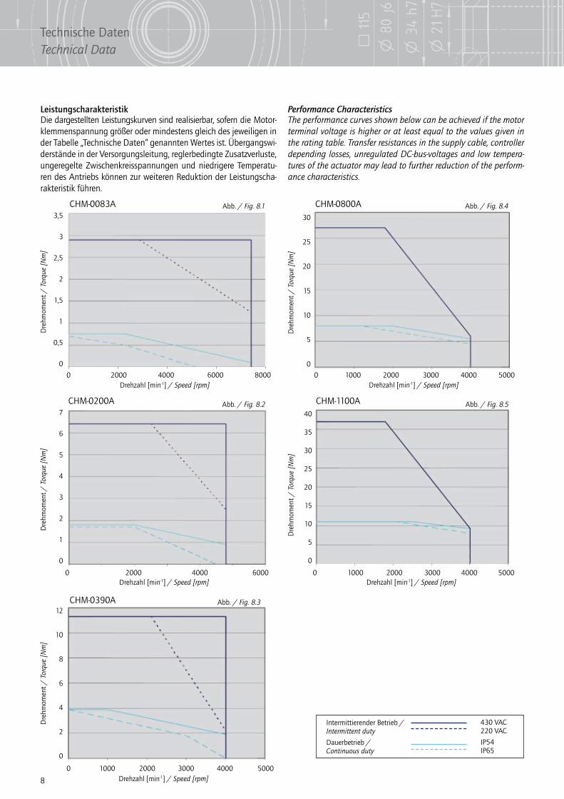
Leistungscharakteristik Performance CharacteristicsDie dargestellten Leistungskurven sind realisierbar, sofern die Motor-klemmenspannung größer oder mindestens gleich des jeweiligen in der Tabelle „Technische Daten“ genannten Wertes ist. Übergangswi-derstände in der Versorgungsleitung, reglerbedingte Zusatzverluste, ungeregelte Zwischenkreisspannungen und niedrigere Temperatu-ren des Antriebs können zur weiteren Reduktion der Leistungscha-rakteristik führen.
The performance curves shown below can be achieved if the motor terminal voltage is higher or at least equal to the values given in the rating table. Transfer resistances in the supply cable, controller depending losses, unregulated DC-bus-voltages and low tempera-tures of the actuator may lead to further reduction of the perform-ance characteristics.
CHM-0800A
CHM-0390A
CHM-0200A CHM-1100A
Abb. / Fig. 8.4
Abb. / Fig. 8.3
Abb. / Fig. 8.2 Abb. / Fig. 8.5
Drehzahl [min-1] / Speed [rpm] Drehzahl [min-1] / Speed [rpm]
Drehzahl [min-1] / Speed [rpm]
Drehzahl [min-1] / Speed [rpm] Drehzahl [min-1] / Speed [rpm]
Dre
hmom
ent /
Tor
que
[Nm
]
Dre
hmom
ent /
Tor
que
[Nm
]
Dre
hmom
ent /
Tor
que
[Nm
]D
rehm
omen
t / T
orqu
e [N
m]
Dre
hmom
ent /
Tor
que
[Nm
]
0 2000 4000 6000 8000 0 1000 2000 3000 4000 5000
0 1000 2000 3000 4000 5000
0 2000 4000 6000 0 1000 2000 3000 4000 5000
7
6
5
4
3
2
1
0
12
10
8
6
4
2
0
30
25
20
15
10
5
0
40
35
30
25
20
15
10
5
0
Intermittierender Betrieb / Intermittent duty
Dauerbetrieb / Continuous duty
430 VAC220 VAC
IP54IP65
3,5
3
2,5
2
1,5
1
0,5
0
Abb. / Fig. 8.1CHM-0083A
8
Technische DatenTechnical Data
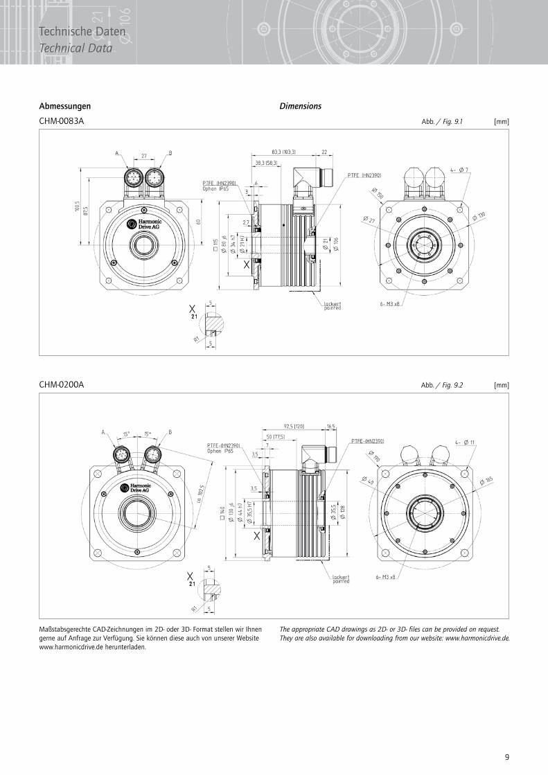
Abmessungen Dimensions
CHM-0083A [mm]
CHM-0200A [mm]
Abb. / Fig. 9.1
Abb. / Fig. 9.2
Maßstabsgerechte CAD-Zeichnungen im 2D- oder 3D- Format stellen wir Ihnen gerne auf Anfrage zur Verfügung. Sie können diese auch von unserer Website www.harmonicdrive.de herunterladen.
The appropriate CAD drawings as 2D- or 3D- files can be provided on request. They are also available for downloading from our website: www.harmonicdrive.de.
9
Technische DatenTechnical Data

CHM-0390A [mm]
CHM-0800A [mm]
Abb. / Fig. 10.1
Abb. / Fig. 10.2
Maßstabsgerechte CAD-Zeichnungen im 2D- oder 3D- Format stellen wir Ihnen gerne auf Anfrage zur Verfügung. Sie können diese auch von unserer Website www.harmonicdrive.de herunterladen.
The appropriate CAD drawings as 2D- or 3D- files can be provided on request. They are also available for downloading from our website: www.harmonicdrive.de.
10
Technische DatenTechnical Data
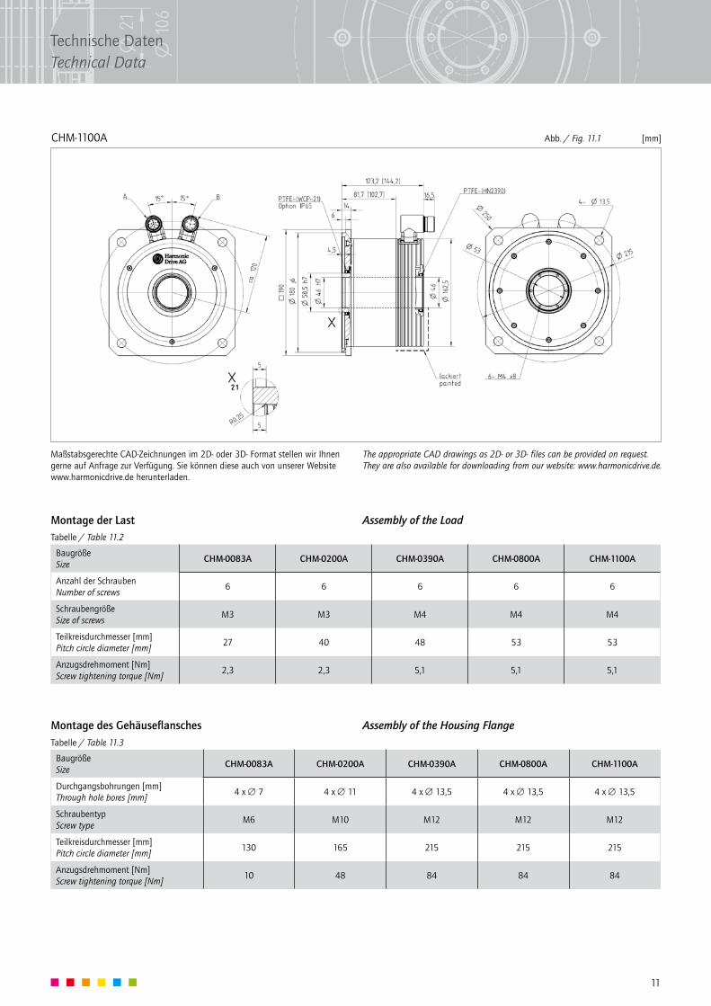
CHM-1100A [mm]Abb. / Fig. 11.1
Maßstabsgerechte CAD-Zeichnungen im 2D- oder 3D- Format stellen wir Ihnen gerne auf Anfrage zur Verfügung. Sie können diese auch von unserer Website www.harmonicdrive.de herunterladen.
The appropriate CAD drawings as 2D- or 3D- files can be provided on request. They are also available for downloading from our website: www.harmonicdrive.de.
Montage der Last Assembly of the Load
Montage des Gehäuseflansches Assembly of the Housing Flange
Baugröße Size
CHM-0083A CHM-0200A CHM-0390A CHM-0800A CHM-1100A
Anzahl der Schrauben Number of screws
6 6 6 6 6
Schraubengröße Size of screws
M3 M3 M4 M4 M4
Teilkreisdurchmesser [mm] Pitch circle diameter [mm]
27 40 48 53 53
Anzugsdrehmoment [Nm] Screw tightening torque [Nm]
2,3 2,3 5,1 5,1 5,1
Tabelle / Table 11.2
Tabelle / Table 11.3
Baugröße Size
CHM-0083A CHM-0200A CHM-0390A CHM-0800A CHM-1100A
Durchgangsbohrungen [mm] Through hole bores [mm]
4 x ∅ 7 4 x ∅ 11 4 x ∅ 13,5 4 x ∅ 13,5 4 x ∅ 13,5
Schraubentyp Screw type
M6 M10 M12 M12 M12
Teilkreisdurchmesser [mm] Pitch circle diameter [mm]
130 165 215 215 215
Anzugsdrehmoment [Nm] Screw tightening torque [Nm]
10 48 84 84 84
11
Technische DatenTechnical Data

03
/20
10
900
187
Deutschland GermanyHarmonic Drive AGHoenbergstraße 1465555 Limburg/Lahn
Technische Änderungen vorbehalten.We reserve the right to make technical changes and modifications without prior notice.
+49 (0)64 31 - 50 08-0 +49 (0)64 31 - 50 08-119
Frankreich Francewww.harmonicdrive.fr
Japan Japanwww.hds.co.jp
Tschechien Czech Republicwww.harmonicdrive.de
Großbritannien UKwww.harmonicdrive.co.uk
Norwegen Norwaywww.servokontroll.no
USA USAwww.harmonicdrive.net
Indien Indiawww.system-controls.com
Niederlande Netherlandswww.linearmotion.skf.com
Spanien Spainwww.harmonicdrive.es
Israel Israelwww.axy-systems.com
Schweden Swedenwww.eie.se
Österreich Austriawww.harmonicdrive.at
Finnland Finlandwww.eie.fi
Italien Italywww.harmonicdrive.it
Schweiz Switzerlandwww.assag.ch
Belgien Belgiumwww.linearmotion.skf.com
Türkei Turkeywww.egmltd.com
Polen Polandwww.harmonicdrive.de
Russland Russiawww.aviton.spb.ru