harmonic planetary gear fem
TRANSCRIPT

Department of Mechanical and Indutrial Engineering Technology
Project 1
MODELLING OF SUN GEAR AND SHAFT
OF A HAMONIC PLANETARY GEAR By
Sandile Shembe (Student No - 201503655)
A mini-project report submitted
in partial fulfilment of the requirements for the module
STRESS ANALYSIS IV (ESA411)
FOR THE DEGREE OF BACHELOR OF
MECHANICAL ENGINEERING TECHNOLOGY
Submitted to
Supervisor - Dr. Daramy Kallon
DEPARTMENT OF MECHANICAL AND INDUSTRIAL ENGINEERING
TECHNOLOGY
FACULTY OF ENGINEERING AND THE BUILT ENVIRONEMNT
UNIVERSITY OF JOHANNESBURG

Modelling of Sun Gear and Shaft of a Harmonic Planetary Gear – ESA411
Page | 1
Submitted: Thursday 17th September, 2015
Marking plan
Chapter Section Description Sum-
mark
Maximum
Marks
1 I Abstract 5 15
II Introduction 5
III Problem formulation 5
2 I Approach 5 20
II Literature review 10
III Methodology 5
3 I Design 8 20
II Simulation (at all four sections) 10
III Results (tabular, graphical) 2
4 I Discussion (interpretation of graphs) 12 15
II List of assumptions 3
5 I Conclusion (location of critical zones) 6 10
II Recommendations 4
References 6 10
Appendices 4
Report layout 4 10
Neatness 3
Presentation 3
Total Marks 100 100
Name: ………………………..……………Student No: ………………………. ………….
Signature: ..................................................Date: …………………………………………...

Modelling of Sun Gear and Shaft of a Harmonic Planetary Gear – ESA411
Page | 2
DECLARATION
I ……………………………………….. Hereby declare that this mini-project report is
wholly my own work and has not been submitted anywhere else for academic credit, either
by myself or another person.
I understand what plagiarism implies and declare that this report embodies my own ideas,
words, phrases, arguments, graphics, figures, results and organization except where reference
is explicitly made to another work.
I understand further that any unethical academic behaviour, which includes plagiarism, is
seen in a serious light by the University of Johannesburg and is punishable by disciplinary
action as stipulated by the university rules and regulations.
Name: ………………………..……………
Student No: ………………………. …….
Signature: ..................................................
Date: ………..............................................
Modelling of Sun Gear and Shaft of a Harmonic Planetary Gear – ESA411
Page | 3
ACKNOWLEDGEMENTS
I would like to express my gratitude to my Lecture Dr Kallon for his guidance and assistance
which helped me to be able to conduct this Project Report appropriately.
He made it clear for me what is required from the readings taken during the lab and also what
is expected in terms of the ELO’s on the discussion.
I would also like to thank my classmates for taking their time assisting me in inventor CAD.

Modelling of Sun Gear and Shaft of a Harmonic Planetary Gear – ESA411
Page | 4
ABSTRACT
This document reports the stress analysis of the Sun Gear and a shaft of a harmonic planetary
gear design assemble. Both Gear and Shaft are manufactured from mild steel. The Material
was chosen taking to considerations the mechanical properties, manufacturability and cost
study. The analysis is done so that critical stress concentrations can be identified and design
changes can be done to minimise chances of failure. Other motives for the analysis is that it is
critical to design transmission components as they possess high risk to passengers of the
motor vehicles.
The shaft and gear must withstand static and dynamic loads exacted on it. The sun gear is
locked on the shaft by a key. Loads varying from 15kN to 25kN directly on the
circumference of the gear. The assembly model is created on Inventor professional as well as
the simulation, then the stress concentration deflection is analysed and discussed in this
document.
The stress analysis of the gear and shaft is clearly illustrated graphically for the interpretation
and design decision. The graph indicates the force on the x-axis and the stress on the y-axis.
Theoretically the graph should be linear and increase proportionally.
The first graph on the table is section A-A, it indicating a true relationship between the load
applied and the stress induced. The stress is increases with the increase in load and the graph
is linear. However on the graph for B-B vs load, the stress increases with the load but it
reaches a point where it is constant.
In conclusion section A-A proved to be the only graph repreasenting true results for stress vs
load analysis.The minimum avarage principal stress is 84.45MPa and the maximum avarage
principal stress is 565.5MPa.The relationship is directly proportional because the as the force
increases the stress also increases.As it was stated on the assumptions the graph for this
material obeys Hookes law of stresses as the relationship is propotional.

Modelling of Sun Gear and Shaft of a Harmonic Planetary Gear – ESA411
Page | 5
Table of Contents
DECLARATION ............................................................................................................................ 2
ACKNOWLEDGEMENTS ............................................................................................................ 3
ABSTRACT .................................................................................................................................... 4
CHAPTER 1 ................................................................................................................................... 9
INTRODUCTION .......................................................................................................................... 9
1.1. Project Background ..................................................................................................... 9
1.2. Problem Formulation................................................................................................... 9
1.2.1 Problem Statement ................................................................................................... 9
1.2.2 Scope of Project ..................................................................................................... 10
1.2.3 Limitations ............................................................................................................. 10
2.1 Introduction [Note: Give a one paragraph summary of this chapter] ....................... 11
2.2 Approach ................................................................................................................... 11
2.3 Literature review ....................................................................................................... 11
2.3.1 The Sun Gear and Shaft of a Harmonic Planetary Gear ........................................ 11
2.3.2 Design and Application of the Sun Gear of a Harmonic Planetary Gear .............. 13
2.3.3 Fatigue and failure of the Sun Gear and Shaft of a Harmonic Planetary Gear
Error! Bookmark not defined.
2.3.4 Engineering Stress Analysis Procedure (Steps in FEM) ....................................... 17
2.3.5 Stress Analysis of the Sun Gear and Shaft of a Harmonic Planetary Gear ........... 18
3.1 Introduction [Note: Give a one paragraph summary of this chapter] ....................... 19
3.2 Design........................................................................................................................ 19
3.3 Simulation (at all four sections) ................................................................................ 21
3.4 Results (tabular and graphical) .................................................................................. 33
4.1 Introduction [Note: Give a one paragraph summary of this chapter] ....................... 34
4.2 Discussions ................................................................................................................ 34
4.3 Assumptions .............................................................................................................. 35
5.1 Introduction [Note: Give a one paragraph summary of this chapter] ....................... 36
5.2 Conclusions ............................................................................................................... 36
5.3 Recommendations ..................................................................................................... 36
REFERENCES ............................................................................................................................. 38

Modelling of Sun Gear and Shaft of a Harmonic Planetary Gear – ESA411
Page | 6
LIST OF FIGURES
Figure 1.1 Planetary gear system illustration……………………………………….9
Figure 2.3.1 Mild steel Stress Vs Strain Curve…………………………………12
Figure 2.3.2.2 (a). Gantry Milling Machine………………………………………..14
Figure 2.3.2.2 (b). Gantry Milling Machine ………………………………………14
Figure 2.3.2.2(c) Other Applications of Planetary gears…………………………14
Figure 2.3.3 (b) fatigue crack……………………………………………………...15
Figure 3.2a Harmonic gear and Shaft 2 D…………………………………….….19
Figure 3.2b Sun Gear 2 D…………………………………………………………19
Figure 3.2.2 Assembly 2 D………………………………………………………..20
Figure 3.4 Stress Vs Force Graph’s……………………………………………….33
Figure 5.2.1 Stress Vs Force (A-A) graphical Representation…………………….36

Modelling of Sun Gear and Shaft of a Harmonic Planetary Gear – ESA411
Page | 7
LIST OF TABLES
Table 3.1 Assemble Bill of Material
Table 3.3.1 Table of Result - 15kN
Table 3.3.2 Table of Result - 17kN
Table 3.3.3 Table of Result - 19kN
Table 3.3.4 Table of Result - 21kN
Table 3.3.5 Table of Result - 23kN
Table 3.3.6 Table of Result - 25kN
Table 3.4 Sectional Planes

Modelling of Sun Gear and Shaft of a Harmonic Planetary Gear – ESA411
Page | 8
LIST OF SYMBOLS or NOMENCLATURE
Symbol Description
P Point Load
x Varying distance
y Displacement
d^2y/dx^2 Moment Integral
dy/dx Slope Integral
Mmax Maximum Moment
Ixx Moment of Inertia
D Diameter
E Modulus of Elasticity
C Integration Constants

Modelling of Sun Gear and Shaft of a Harmonic Planetary Gear – ESA411
Page | 9
CHAPTER 1
INTRODUCTION
----------------------------------------------------------------------------------------------------------------
1.1. Project Background
Figure 1.1 Planetary gear system illustration
The purpose for this project is to identify critical location where the beam is likely to failure.
The analysis is done based on stresses induced by varying the load acting on the gear. The
material for the whole assemble is mild steel. Investigate the material selected satisfy the four
main properties or criteria namely High tensile and endurance strength allowing the material
to withstand static and dynamic loads respectively.
This sun gear and shaft to be design is for an automatic transmission of a Bell Front End
Loader. Then using Autodesk Inventor Professional 2015 both the sun gear and shaft is
designed, and simulate is run to identify stress concentration as well as deflection. The results
will be inspected, conclusion and recommendations are pointed out.
1.2. Problem Formulation
1.2.1 Problem Statement
A shaft of an automatic transmission planetary gear system carries a sun gear linked to three
gears orbiting around the planetary ring gear.
The assembly components are made up of mild steel. The loading on the shaft need to be
analysed for failure stress analysis. The aim is to find the location of the Fatigue and direct
stresses induced on assemble that may result in to mechanical failure. The load applied is
varied for different stress values.
The shaft geometry and material selected must be able to allow it to withstand the load of
gear and the point load varying from 15kN to 25kN acting on top of the gear and the beam is
fixed on the left-hand.

Modelling of Sun Gear and Shaft of a Harmonic Planetary Gear – ESA411
Page | 10
1.2.2 Scope of Project
Designing a sun gear and shaft of harmonic planetary gears, and then selecting mild steel as a
base material that will provide acceptable yield strength, cost effective and that has good
manufacturability.
The design assemble needs to simulated for stress analysis results and conclusion need to be
drawn based on the results. CAD simulation is done to investigate the degree of failure of the
selected material; this is achieved by data inputting material properties on the design model.
Deflection and slope is calculated for the designed assembly at maximum point load of 25KN
applied at 42mm from the fixed end.
The following is guideline or scope of the project.
1. Literature review on material selection for planetary gears.
2. Select mild steel as a material for the shaft, gear and key of the planetary system.
3. Determine the slope and deflection at maximum loading.
4. Model the design and do stress analysis on inventor.
1.2.3 Limitations
Since material is assigned based on the procedure stated on this report and can only be
proved by calculations and stress analysis on Inventor Auto Cad.The limitations are practical
testing of the material selected, because selection was done by investigating the material used
in industry then selected on the standard tables.
To ensure proper selection of material, hardness test must be done on the material then a
prototype must be manufactured to do precise test

Modelling of Sun Gear and Shaft of a Harmonic Planetary Gear – ESA411
Page | 11
CHAPTER 2
Approach, Literature Review and Methodology
----------------------------------------------------------------------------------------------
2.1 Introduction
The engine drives the transmission, and then the transmission will transmit the drive through
the propeller shaft to the axle for wheel drive. In the system there must be a sun gear and
shaft of a planetary gear system, this system or mechanism convert the reciprocating motion
to rotational motion. Therefore the harmonic shaft is induced with mechanical stresses and
then material selection becomes a critical or import factor in the design so as to try and
minimise those stresses. The literature covers the theory behind material selection,
application and methodology of designing effective structures.
2.2 Approach
In this design the history and applications of a sun gear and a harmonic shaft is investigated.
The sun gear and shaft being designed is used on the automatic transmission. In this design
the shaft and the gear are mild steel and assemble is simulate on CAD for stress analysis and
deformation, results are documented on chapter three.
The material to be selected must also have the shaft diameter as a standard size so that the
design can be cost effective. Results will be illustrated by the drawing programme so that it
can be concluded about the impact of the applied force on the shaft of selected material.
2.3 Literature review
2.3.1 The Sun Gear and Shaft of a Harmonic Planetary Gear
The sun gear is located at the centre of the planetary gears traveling on the ring gear. The sun
gear is transmitting torque from the shaft to the planet gears.
Therefore the material of the sun gear must be able to withstand bending and torsional
stresses induced by the motor driving the harmonic shaft. When the sun and planetary gear
system was invented the aim was to convert reciprocation motion to rotary motion. In trying
to convert the reciprocating motion to rotary motion the planetary gears are exposed to
mechanical stress in different planes.

Modelling of Sun Gear and Shaft of a Harmonic Planetary Gear – ESA411
Page | 12
The following performance material indices are considered for the material selection of
transmission gears.
surface fatigue limit
root bending fatigue limit
wear resistance of tooth’s flank and
Machinability.
The material used for the gear and shaft design is mild steel.
Mild Steel
Mild steel composition consist of iron alloy containing 0.3 % carbon ,but the range is
normally between 0.1-0.25 %.It main characteristics are its ductility and malleability.
Those characteristics are important and therefore mild steels are used to manufacture
fasteners and also used in railings and decorative gates.
The property of malleability allows mild steels to be bent, twisted without fracture and
fatigue.
Figure 2.3.1 Mild steel Stress Vs Strain Curve (Design of Steel Structures at Indian Institute
of Technology Madras)
Modelling of Sun Gear and Shaft of a Harmonic Planetary Gear – ESA411
Page | 13
Low Carbon steels
Low carbon steels has less composition of carbon, ranging from 0.05% to 0.3%.Generally in
vehicle body panels, pipes chains, rivets and fasteners the composition of carbon is between 0
.05 And 0.2 while on gears, shafts it ranges from 0.2 – 0.3 % of C.
Low carbon steels are normally used where high strength is not a requirement.
2.3.2 Design and Application of the Sun Gear of a Harmonic Planetary Gear
2.3.2.1 Design of the Sun Gear of a Harmonic Planetary Gear
Transmissions of this century are becoming more based on high speeds and precision which
then require gear systems with special design.
Therefore planetary gears are mostly used in machines that are required to transfer
information, energy and materials. The design is in such a way that there are no internal
backlash or minimal if complex to ignore totally. The design of harmonic gears have
advantages of high output capacity on the bearing.
The other advantages of modern design of harmonic gears high torque capacity, precise
positioning geometry, compact design, single stage high ratios and high effectiveness.
Planetary gears sizes and configuration vary widely depending on desired speed ratios and
design requirements. That is an advantage that allows them to be used in various applications
for example in clocks, car mirrors, toys, automobile transmissions and turbine engines.
2.3.2.2 Application of the Sun Gear of a Harmonic Planetary Gear
An example of application of sun gear of harmonic planetary gear mechanism is a gantry
milling machine of large turbine components. This machine has high cutting forces going up
to 30KN.
The harmonic planetary gear system design is able to handle the pre-load torque that can be
varied which the machine operating mode. In this application there are very high
accelerations in torque and precision is also important as this is governed by a co-ordinate
system. When one actuator of the milling machine acts as a brake it increases the pre-load
which remove the backlash in the pinion ring and the torsional stiffness is increased as well.
And the advantages of this system arrangement are high performance without comprising
accuracy. Below the machine is illustrated.

Modelling of Sun Gear and Shaft of a Harmonic Planetary Gear – ESA411
Page | 14
Figure 2.3.2.2 (a). Gantry Milling Machine
Figure 2.3.2.2 (b). Gantry Milling Machine
Figure 2.3.2.2(c) Other Applications of Planetary gears

Modelling of Sun Gear and Shaft of a Harmonic Planetary Gear – ESA411
Page | 15
2.3.3 Fatigue and failure of the Sun Gear and Shaft of a Harmonic Planetary Gear
Figure 2.3.3(a) Failure due to heavy static loads induced.
Figure 2.3.3 (b) According to the research done by the K S Rangasamy College of
Technology, the failure that was observed here was caused by rust then the gear failed
because of fatigue crack.
Modelling of Sun Gear and Shaft of a Harmonic Planetary Gear – ESA411
Page | 16
2.3.4 Engineering Materials
Materials selected for gear application are expected to provide a combination of
characteristics without comprising cost in trying to satisfy the requirements. Physical
properties that are significant for gear material are fatigue, shear, static strength, wear
resistance, toughness and strength at high temperatures.
Engineering materials properties vary because they depend on a wide range of factors, such
as chemical composition, processes of manufacture, molecular defects, heat treatment and
temperature.
Usually on ATSM tables and charts, the common properties that are specified are the
ultimate, yield strength, compressive strength, Modulus of elasticity normally when looking
in tension and torsion, then Brinell hardness and finally fatigue stress factors.
Constrains in selecting the gear material are the component geometry, manufacturability and
cost effectiveness.
For the purpose of this project the materials that are being investigated are Plain carbon
steels, medium carbon steels and low alloy ASTM High strength steel.
Plain carbon steels
.
2.3.5 Engineering Materials Selection Procedure
Gears can be made from variety of material depending on application needs, for example they
can be manufactured from Steel, Cast Iron, nylon, acetal etc.
Normally the first step in selecting the material is to gather information about the
performance requirements of the system where the gear will be used. Thus assist on choosing
the material with sufficient physical and chemical properties, then processing requirements.
According NSI-AGMA 2004-B89 Gear Material Manual, there seven guidelines used in this
project for material selection for sun gear and shaft they are listed below:-
1. Physical Mechanical Properties
2. Grade and Heat Treatment
3. Manufacturability
4. Availability and Cost
5. Hardenability and Size Effects
6. Cleanliness
7. Dimensional Stability

Modelling of Sun Gear and Shaft of a Harmonic Planetary Gear – ESA411
Page | 17
Other requirements for material selection during design stage are, design requirements such
as knowing what the application of the component to be designed, essential requirements that
need to be met e.g. strength and stiffness etc. The material life is mostly affected by corrosion
and fatigue.
The geometric and material properties also are a requirements and these assist in determining
equations for constrains such as yield, fracture, buckling etc.
2.3.6 Engineering Stress Analysis Procedure (Steps in FEM)
Essential steps to be followed for stress analysis are as follows:-
Discretization
In this step it where the nodes are selected and the element mesh is formed either in
2d or 3D.The mesh is a formation of shapes such as triangles, quadrilaterals,
tetrahedral, prismatic etc.
Selection of element to be analysed
Selection of displacement function
Displacement function can any polynomial, that function will produce an approximate
result and it will also satisfy basic requirements for the analysis.
Defining the stress verses strain relationship
Derive the element stiffness matrix
To derive the element stiffness matrix, nodal forces are used because they are related
to the stiffness. In this step the material is also specified.
The function consist of force, stiffness and displacement.
Derivation of overall matrices and equations
In this step the matrices for each nodal points is assembled to form a global.
Solving for nodal displacements
Specify the boundary conditions
Solving for element forces applied at nodes
Interpretation of the results

Modelling of Sun Gear and Shaft of a Harmonic Planetary Gear – ESA411
Page | 18
2.3.7 Stress Analysis of the Sun Gear and Shaft of a Harmonic Planetary Gear
Due to the mechanical movements in the transmission, the sun gear and harmonic planetary
gears become under mechanical stresses. These stresses results into catastrophic failures if
unidentified.
In the planetary gears the stresses increases as the torque increases. The vibrations that occur
during rotation in the system courses fatigue in critical areas where the shafts are fixed. In
design of planetary gears, finite element analysis is applied to a single tooth so that results are
accurate. The material strength is the key factor in major consideration for the operational
loading. CAD software’s are used to analyse the structures programmes such as Pro
Engineer, PTC creo, solid works and Inventor.
2.4 Methodology
The design methodology followed could be summarized as follows;
Step 1: Modelling assemble consisting of a gear, shaft and key.
Step 2: Select Mild steel as base material.
Step 3: Apply different loads ranging from 15 kN to 25kN with increments of 2 kN
Step 4: Create a simulation and run.
Step5: Assemble is then analysed for weight, stress and displacement.
Step6: The results are then compared to the commercial figures and observed if they
are still within mechanical operational requirement, and if not then iterations from
step 3 are necessary.
Design constraints
The dimensions must not be altered.
The load position and increments must be kept constant throughout.

Modelling of Sun Gear and Shaft of a Harmonic Planetary Gear – ESA411
Page | 19
CHAPTER 3
Modelling of Sun Gear and Shaft
----------------------------------------------------------------------------------------------
3.1 Introduction
The design consist of assemble of a gear, shaft and key. The structure forms a cantilever
beam fixed on the left-hand of the beam. The position of the load is 44mm from the fixed
wall. The magnitude of the load applied is varied from 15kN to 25kN and simulation is done
to identify the location of critical failure points.
3.2 Design
Below there are 2 dimensional drawings for the assemble and its parts
Figure 3.2a.Gear and shaft assemble.
Figure 3.2b.Gear.

Modelling of Sun Gear and Shaft of a Harmonic Planetary Gear – ESA411
Page | 20
Figure 3.2c. shaft
Figure 3.2d.Gear and shaft assemble with dimensions (Illustration)
Table 3.1 Assemble Bill of Material
Bill of Material
Parts List Material Quantity
Gear Steel, Mild 1
Shaft Steel, Mild 1
Key Steel, Mild 1

Modelling of Sun Gear and Shaft of a Harmonic Planetary Gear – ESA411
Page | 21
3.3 Simulation (at all four sections)
Table 3.3.1 Table of Result - 15kN
Name Minimum Maximum
Volume 45817.5 mm^3
Mass 0.359668 kg
Von Mises Stress 0.0856843 MPa 678.622 MPa
1st Principal Stress -224.781 MPa 806.017 MPa
3rd Principal Stress -815.195 MPa 247.271 MPa
Displacement 0 mm 0.194262 mm
Safety Factor 0.30503 ul 15 ul
Von Mises Stress

Modelling of Sun Gear and Shaft of a Harmonic Planetary Gear – ESA411
Page | 22
1st Principal Stress
3rd Principal Stress

Modelling of Sun Gear and Shaft of a Harmonic Planetary Gear – ESA411
Page | 23
Table 3.3.2Table of Result - 17kN
Name Minimum Maximum
Volume 45817.5 mm^3
Mass 0.359668 kg
Von Mises Stress 0.649899 MPa 1081.39 MPa
1st Principal Stress -386.234 MPa 1406.22 MPa
3rd Principal Stress -1389.3 MPa 404.037 MPa
Displacement 0 mm 0.37656 mm
Safety Factor 0.191421 ul 15 ul
Von Mises Stress

Modelling of Sun Gear and Shaft of a Harmonic Planetary Gear – ESA411
Page | 24
1st Principal Stress
3rd Principal Stress

Modelling of Sun Gear and Shaft of a Harmonic Planetary Gear – ESA411
Page | 25
Table 3.3.3 Table of Result - 19kN
Name Minimum Maximum
Volume 45817.5 mm^3
Mass 0.359668 kg
Von Mises Stress 1.33718 MPa 1629.75 MPa
1st Principal Stress -566.569 MPa 2118.43 MPa
3rd Principal Stress -2031.03 MPa 555.983 MPa
Displacement 0 mm 0.580473 mm
Safety Factor 0.127013 ul 15 ul
Von Mises Stress

Modelling of Sun Gear and Shaft of a Harmonic Planetary Gear – ESA411
Page | 26
1st Principal Stress
3rd Principal Stress

Modelling of Sun Gear and Shaft of a Harmonic Planetary Gear – ESA411
Page | 27
Table 3.3.4 Table of Result - 21kN
Name Minimum Maximum
Volume 45817.5 mm^3
Mass 0.359668 kg
Von Mises Stress 2.08496 MPa 2238.68 MPa
1st Principal Stress -765.845 MPa 2913.13 MPa
3rd Principal Stress -2740.36 MPa 718.377 MPa
Displacement 0 mm 0.805869 mm
Safety Factor 0.092465 ul 15 ul
Von Mises Stresses

Modelling of Sun Gear and Shaft of a Harmonic Planetary Gear – ESA411
Page | 28
1st Principal Stresses
3rd Principal Stresses
Modelling of Sun Gear and Shaft of a Harmonic Planetary Gear – ESA411
Page | 29
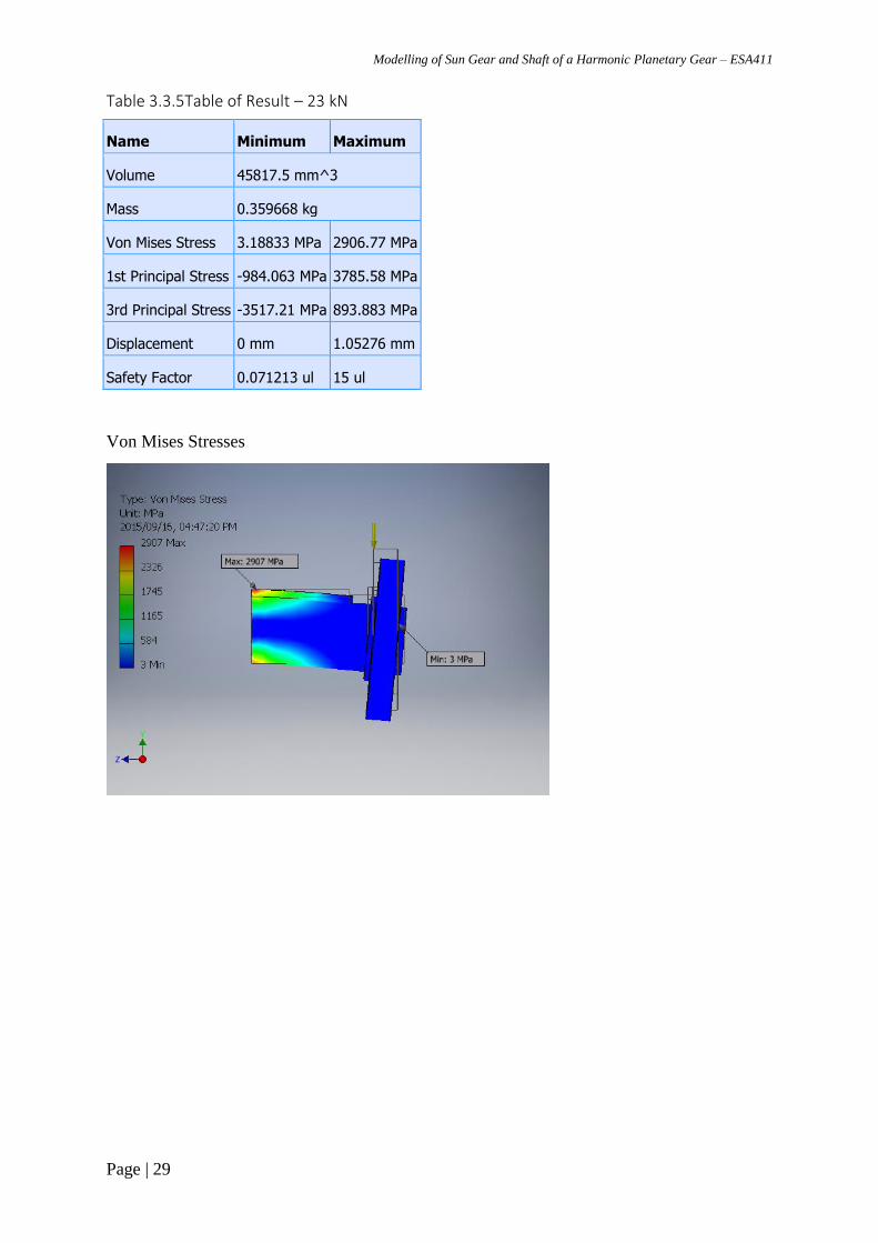
Table 3.3.5Table of Result – 23 kN
Name Minimum Maximum
Volume 45817.5 mm^3
Mass 0.359668 kg
Von Mises Stress 3.18833 MPa 2906.77 MPa
1st Principal Stress -984.063 MPa 3785.58 MPa
3rd Principal Stress -3517.21 MPa 893.883 MPa
Displacement 0 mm 1.05276 mm
Safety Factor 0.071213 ul 15 ul
Von Mises Stresses

Modelling of Sun Gear and Shaft of a Harmonic Planetary Gear – ESA411
Page | 30
1st Principal Stresses
3rd Principal Stresses

Modelling of Sun Gear and Shaft of a Harmonic Planetary Gear – ESA411
Page | 31
Table 3.3.6 Table of Result – 25 kN
Name Minimum Maximum
Volume 45817.5 mm^3
Mass 0.359668 kg
Von Mises Stress 3.31356 MPa 3633.71 MPa
1st Principal Stress -1221.26 MPa 4734.92 MPa
3rd Principal Stress -4361.68 MPa 1083.58 MPa
Displacement 0 mm 1.32112 mm
Safety Factor 0.0569665 ul 15 ul
Von Mises Stresses

Modelling of Sun Gear and Shaft of a Harmonic Planetary Gear – ESA411
Page | 32
1st Principal Stresses
3rd Principal Stresses

Modelling of Sun Gear and Shaft of a Harmonic Planetary Gear – ESA411
Page | 33
3.4 Results (tabular and graphical)
Table 3.4 Sectional Planes
F (kN) A-A B-B C-C D-D
15 84,45 -18,65 -121,7 -121,7
17 151,25 -27 -207 -207
19 238,5 -30 -298,5 -567
21 338 -30 -398 -766
23 447 -30 -507 -984
25 565,5 -30 -625,5 -1221
Graphical Representation
Figure 3.4 Stress Vs Force Graph’s

Modelling of Sun Gear and Shaft of a Harmonic Planetary Gear – ESA411
Page | 34
CHAPTER 4
Discussion of Results - Stress Analysis of the Sun Gear and Shaft
----------------------------------------------------------------------------------------------
4.1 Introduction
This chapter discusses the results of the stress analysis report generated from Inventor
simulation. The stresses that were developed in the analysis were, then tabulated and used to
derive graphs that represent the relationship between the stress and the force. The readings
are separated by sectional planes namely A-A, B-B, C-C & D-D. These graphs are clearly
explained in this chapter and it can be seen that only the graph of section A-A is on the
positive axis thus shows the where there is high concentration of stresses. Assumptions are
also stated in this chapter for the design.
4.2 Discussions
4.2.1 Interpretation of the first four graphs
The stress analysis of the gear and shaft is clearly illustrated graphically for the interpretation
and design decision. The graph indicates the force on the x-axis and the stress on the y-
axis.Theoritically the graph should be linear and increase proportionally.
The first graph on the table is section A-A ,it indicating a true relationship between the load
applied and the stress induced.The stress is increases with the increase in load and the graph
is linear. However on the graph for B-B vs load ,the stress increases with the load but it
reaches a point where it is constant.
The graph for section D-D & C-C the relationship is linear but the trend is ever decreasing
which indicates that as the load increases the stress is lesser .It is then found that as you move
closer to the load location the stress tend to decrease even when the load is increased.
From the graphical interpretation it can be deduced that the stress is concentrated more on the
fixed end between the shaft and the wall.as it is shown on figure 4.2.1 the concentration is
more on the fixed wall.

Modelling of Sun Gear and Shaft of a Harmonic Planetary Gear – ESA411
Page | 35
4.2.1 Stress Concentration critical points illustration
4.3 Assumptions
1. The material in the model complies with Hooke’s law and therefore stress is directly
proportional to strain.
2. The induced displacements are small enough to ignore the change in stiffness caused
by loading.
3. Boundary conditions do not vary during the application of loads. Loads must be
constant in magnitude, direction, and distribution. They should not change while the
model is deforming.
4. All loads are applied slowly and gradually until they reach their full magnitudes. After
reaching their full magnitudes, loads remain constant (time-invariant).

Modelling of Sun Gear and Shaft of a Harmonic Planetary Gear – ESA411
Page | 36
CHAPTER 5
Conclusions and Recommendations
----------------------------------------------------------------------------------------------
5.1 Introduction
This chapter documents the conclusion about the stress analysis performed on assemble. The
stresses from the graphs were tabulated and grouped into sections. Plane A-A graph produced
results that shows the true relationship between stress induced and force applied.
Recommendations are also stated in this chapter, recommendations such as position of the
load and method of calculating the sectional stresses need to be investigated for accuracy.
5.2 Conclusions
5.2.1 Interpretation of final graph (Location of critical zones)
The graph that possess more appropriate results is for section A-A since the relationship of
the stress and force is proportional. Below is the graph of section AA. The minimum avarage
principal stress is 84.45MPa and the maximum avarage principal stress is 565.5MPa.
Figure 5.2.1 Stress Vs Force (A-A) graphical Representation
The minimum avarage principal stress is 84.45MPa and the maximum avarage principal
stress is 565.5MPa.The relationship is directly proportional because the as the force increases
the stress also increases.As it was stated on the assumptions the graph for this material obeys
Hookes law of stresses as the relationship is propotional.The sectional stresses indicate that as
the planes shift away from the critical stress area the stress concentration decreases and that is
clear when the assemble simulate is viewd.

Modelling of Sun Gear and Shaft of a Harmonic Planetary Gear – ESA411
Page | 37
The graphical results also illustrate the material selected obeys Hooks law.The material is
alos not brittle ,that is proven by the analysis since it didn’t breck but it resisted the and
consumed the stress applied.
Recommendations
Load needs to be applied at the centre of the gear so that it can act in line with the
weight of the gear.
The gear need to be designed with the tooth for more accurate results, and remove the
holes because they affect the stress.
The method of calculating the sectional stresses need to be investigated for accuracy.

Modelling of Sun Gear and Shaft of a Harmonic Planetary Gear – ESA411
Page | 38
REFERENCES
Examples of References
1. http://www.ehow.com/facts_6961115_properties-uses-mild-steel.html
2. Analysis of Stresses and Deflection of Sun Gear by Theoretical and ANSYS
Method_PDF
3. 02/05/2015,http://www.ezlok.com/TechnicalInfo/MPCarbonSteel.html
4. (Published in 1997) Strength of Materials For Technicians ;J.G Drosky
5. (Published: 2011-01-04)Mechanics of Materials 6th Edition .James Gere
6. DA6-BeamFormulas Downloaded document
7. (1 Mar. 2010) Shigley's Mechanical Engineering Design 9th Edition by Budynas,
Richard, Nisbett, Keith
8. Marks' Standard Handbook for Mechanical Engineers
Appendix_B.pdf
9. 10/05/2015,https://www.google.co.za/search?q=planetary+gear+transmission
10. 06/05/2015,https://www.google.co.za/search?q=Gantry+Milling+Machine
11. 10/05/2015,Carbon Steel Hand Book by D. Gandy; EPRI Project Manager
12. Developments In Abrasive WaterJet Technology
13. http://www.wjta.org/wjta/New_Developments_etc.asp, Accessed August 2011
14. WaterJet Technology
15. http://www.todaysconcretetechnology.com/waterjet-cutting-will-create-new-
opportunities-for-designers.html, Accessed August 2011

Modelling of Sun Gear and Shaft of a Harmonic Planetary Gear – ESA411
Page | 39
Appendices