harmonisation of pavement markings and national pavement ... · specifications/design criteria for...
TRANSCRIPT

Research Report AP-R578-18
Harmonisation of Pavement Markings and National Pavement Marking Specification
Harmonisation of Pavement Markings and National Pavement Marking Specification
Prepared by
Georgia O'Connor, Caroline Evans and Peter Cairney
Publisher
Austroads Ltd. Level 9, 287 Elizabeth Street Sydney NSW 2000 Australia Phone: +61 2 8265 3300 [email protected] www.austroads.com.au
Project Manager
Ron Koorengevel
Abstract
Pavement markings constitute a key element of safe system infrastructure. They are a significant road asset of interest to all road users. There are variations in road agency practice with respect to longitudinal and transverse linemarking types and widths and other pavement markings; as a result, many do not comply with Australian Standard AS 1742.2:2009.
Specifications for pavement markings and materials differ between jurisdictions and the intervention levels for the replacement/remarking of pavement markings also differ. There is a strong need for harmonised performance based specifications/design criteria for pavement. The development of a harmonised performance-based specification for linemarkings has been on the agenda for the Austroads Road Authority Pavement Markings Group for several years.
This report documents a project undertaken to achieve national harmonisation through the development of national performance specification/criteria for pavement markings. The project investigated:
• longitudinal and transverse linemarking types and widths and other pavement markings used by different road agencies (States and Territories) with the aim of harmonising them as far as practical
• road agency pavement marking specifications in order to develop a national performance specification for pavement markings.
Emphasis in this project was the harmonisation of the widths and specifications of stop lines, give-way lines, turns, pedestrian cross walk lines, dividing lines for multi-lane roads, tram lines, pavement arrows, pavement letters, audio-tactile line markings and wide centreline treatments.
About Austroads
Austroads is the peak organisation of Australasian road transport and traffic agencies.
Austroads’ purpose is to support our member organisations to deliver an improved Australasian road transport network. To succeed in this task, we undertake leading-edge road and transport research which underpins our input to policy development and published guidance on the design, construction and management of the road network and its associated infrastructure.
Austroads provides a collective approach that delivers value for money, encourages shared knowledge and drives consistency for road users.
Austroads is governed by a Board consisting of senior executive representatives from each of its eleven member organisations: • Roads and Maritime Services New South Wales • Roads Corporation Victoria • Queensland Department of Transport and Main Roads • Main Roads Western Australia • Department of Planning, Transport and Infrastructure
South Australia • Department of State Growth Tasmania • Department of Infrastructure, Planning and Logistics
Northern Territory • Transport Canberra and City Services Directorate,
Australian Capital Territory • The Department of Infrastructure, Regional Development
and Cities • Australian Local Government Association • New Zealand Transport Agency.
Keywords
harmonisation, linemarkings, pavement markings, specification, standards
ISBN 978-1-925671-72-8
Austroads Project No. AAM2111
Austroads Publication No. AP-R578-18
Publication date August 2018
Pages 127
© Austroads 2018
This work is copyright. Apart from any use as permitted under the Copyright Act 1968, no part may be reproduced by any process without the prior written permission of Austroads.
Acknowledgements
The extensive contributions of members of the RAPMG are acknowledged. This project has been coordinated in consultation with Roads Australia to ensure that it meets their requirements in terms of harmonised longitudinal line widths and national specifications. RIAA, 3M and other industry representatives have also been included in the consultation.
This report has been prepared for Austroads as part of its work to promote improved Australian and New Zealand transport outcomes by providing expert technical input on road and road transport issues.
Individual road agencies will determine their response to this report following consideration of their legislative or administrative arrangements, available funding, as well as local circumstances and priorities.
Austroads believes this publication to be correct at the time of printing and does not accept responsibility for any consequences arising from the use of information herein. Readers should rely on their own skill and judgement to apply information to particular issues.

Harmonisation of Pavement Markings and National Pavement Marking Specification
Austroads 2018 | page i
Summary
Pavement markings constitute a key element of safe system infrastructure to all road users. However, specifications for pavement markings and materials differ between road agencies and the intervention levels for the replacement/remarking of pavement markings also differ; as a result, many do not comply with Australian Standard AS 1742.2:2009. There is a strong need for harmonised performance-based specifications/design criteria for pavement markings. The development of a harmonised performance-based specification for linemarkings has been on the Austroads Road Authority Pavement Markings Group (RAPMG) agenda for several years.
To achieve this outcome, the project involved an investigation of longitudinal and transverse linemarking types and widths and other pavement markings. The work was undertaken through an analysis of the current Australian Standards and a survey of the current practices implemented by the different road agencies. These were then compared to determine the preferred approach. The project also involved an investigation of road agency pavement marking specifications in order that a national performance specification for pavement markings could be developed.
This report documents the work for Years 1 (2016–17) and 2 (2017–18). The work in Year 1 involved:
• a review of current practice with respect to longitudinal linemarking
• a review of current performance specifications
• the development of an outline of the agreed harmonised good practice
• a justification for the move as determined by the RAPMG
• an assessment of the benefits and challenges of harmonised linemarking practice
• the development of the criteria required for a national performance specification for pavement markings.
The work in Year 2 resulted in:
• agreed standards for audio-tactile linemarkings (ATLM)
• agreed dimensions for wide-centreline treatments and diagonal markings
• new information on how to maintain thermoplastic ATLM
• draft specifications for pavement markings
• advice on intervention levels.
It was also agreed that there was a need to include the requirements for automated vehicles which required improved and consistent pavement marking. Reports have suggested that edge lines need to be 150 mm wide with a minimum retroreflectivity of 150 millicandela (mmcd/lux/m2; mcd). Intervention levels in Australian standards are already 150 mcd and some road agencies are already installing 150 mm wide edge lines. The majority of road agencies have agreed to adopt the standard, recognising that further work may be necessary as the requirements for autonomous vehicles become better understood, especially as the vehicle industry is not represented on RAPMG. Further integration of information obtained from vehicle manufacturers is also required.
The RAPMG also acknowledged that there may be issues with the level of contrast between the pavement markings and light aggregates used to surface the road because this can also cause issues for autonomous vehicles. This has been addressed in the draft specification. It was agreed by the majority of road agencies that all pavement markings need to be machine readable.
While all attempts have been made to seek harmonisation, it is recognised and accepted that some road agencies may have warranted reasons to deviate from specific parts of this document and hence may develop their own supplementary policy/instructions.
Harmonisation of Pavement Markings and National Pavement Marking Specification
Austroads 2018 | page ii
Contents
Summary ......................................................................................................................................................... i
1. Introduction ............................................................................................................................................ 1 1.1 Background ...................................................................................................................................... 1 1.2 Purpose of the Project ...................................................................................................................... 1 1.3 Objectives ......................................................................................................................................... 2 1.4 Relevant Groups .............................................................................................................................. 2 1.5 Outcomes of Years 1 and 2 of the Project ....................................................................................... 2
2. Overview of Current Practice to Harmonise Linemarkings ............................................................... 4 2.1 Current Standards for Selected Linemarkings ................................................................................. 4
2.1.1 Longitudinal Lines................................................................................................................ 4 2.1.2 Stop Lines ............................................................................................................................ 6 2.1.3 Give-way Lines .................................................................................................................... 6 2.1.4 Turn Lines ............................................................................................................................ 7 2.1.5 Pedestrian Cross-walk Lines ............................................................................................... 7 2.1.6 Dividing Lines on Multi-lane Roads ..................................................................................... 7 2.1.7 Continuity Lines ................................................................................................................... 7 2.1.8 Tram, Tramway and Transverse Lines................................................................................ 7 2.1.9 Audio-tactile Linemarkings .................................................................................................. 8 2.1.10 Wide-centreline Treatments ................................................................................................ 8 2.1.11 Pavement Arrows ................................................................................................................ 8 2.1.12 Pavement Letters and Numerals ....................................................................................... 14 2.1.13 Bike Paths/Shared Paths .................................................................................................. 15
2.2 Harmonised Linemarking Practice ................................................................................................. 18
3. Current Linemarking Practice in Australia ........................................................................................ 20 3.1 Methodology ................................................................................................................................... 20
3.1.1 Survey Participants............................................................................................................ 20 3.1.2 Survey Questions .............................................................................................................. 20
3.2 Preliminary Results from each Agency .......................................................................................... 22 3.2.1 Summary of Responses to Question 1–9 and 12–14 ....................................................... 22 3.2.2 Summary of Responses – ATLM Installation Methods ..................................................... 27 3.2.3 Summary of Responses – Maintenance of ATLM ............................................................. 29
4. Agreed Harmonisation of Good Practice .......................................................................................... 30 4.1 Preferred Approaches to Linemarking Practice ............................................................................. 30
4.1.1 Stop and Give-way Lines .................................................................................................. 30 4.1.2 Optional Broken Turn Line ................................................................................................ 31 4.1.3 Turn Lines .......................................................................................................................... 31 4.1.4 Pedestrian Crosswalk Guidelines ...................................................................................... 32 4.1.5 Replacement of Dividing Lines for Multi-lane Roads ........................................................ 32 4.1.6 Tram, Tramway and Transverse Lines.............................................................................. 32 4.1.7 Audio-tactile Linemarkings (ATLM) ................................................................................... 33 4.1.8 Wide-centrelines Treatments (WCLT) ............................................................................... 33 4.1.9 Pavement Arrows .............................................................................................................. 34

Harmonisation of Pavement Markings and National Pavement Marking Specification
Austroads 2018 | page iii
4.1.10 Pavement Letters and Numerals ....................................................................................... 37 4.1.11 Bike Paths/Shared Paths .................................................................................................. 37
4.2 Justification for the Move to Preferred Markings ............................................................................ 37 4.2.1 Proposed Line Types ........................................................................................................ 38 4.2.2 Stop and Give-way Lines .................................................................................................. 39 4.2.3 Turn Lines .......................................................................................................................... 39 4.2.4 Pedestrian Cross-walk Lines ............................................................................................. 39 4.2.5 Replacement of Dividing Lines for Multi-lane Roads in Urban Areas ............................... 39 4.2.6 Tram, Tramway and Transverse Lines.............................................................................. 39 4.2.7 Audio-tactile Linemarkings ................................................................................................ 40 4.2.8 Wide-centreline Treatments .............................................................................................. 41 4.2.9 Pavement Arrows .............................................................................................................. 43 4.2.10 Pavement Letters and Numerals ....................................................................................... 43 4.2.11 Bike Paths/Shared Paths .................................................................................................. 43 4.2.12 Other Line Types ............................................................................................................... 44
4.3 Agreed Approaches ........................................................................................................................ 44 4.4 ATLM Experimental Testing ........................................................................................................... 45
4.4.1 Northern Territory .............................................................................................................. 45 4.4.2 Victoria ............................................................................................................................... 46 4.4.3 New South Wales .............................................................................................................. 46 4.4.4 Western Australia .............................................................................................................. 46
5. Conclusions and Recommendations ................................................................................................. 47 5.1 Criteria of Clauses .......................................................................................................................... 47 5.2 Challenges to Achieving a National Specification .......................................................................... 47 5.3 Development of Requirements ....................................................................................................... 48 5.4 Further Work with Standards Australia .......................................................................................... 49 5.5 Where to Next? .............................................................................................................................. 49
References ................................................................................................................................................... 51
Appendix A Roads Australia Report on Technical Specifications and Procurement ................... 53
Appendix B Specifications and Drawings ......................................................................................... 55
Appendix C International Review of Audio-tactile Linemarkings.................................................... 87
Appendix D Draft National Specification for Longitudinal Pavement Marking ............................ 106
Glossary of Terms ..................................................................................................................................... 125
Acronyms ................................................................................................................................................... 127
Tables
Table 3.1: Summary of survey questions ................................................................................................ 21 Table 3.2: Responses to survey questions ............................................................................................. 22 Table 4.1: Summary of preferred approaches to linemarking practice ................................................... 30 Table 4.2: Audio-tactile linemarking preferred specifications for edge line and dividing/separation line ........................................................................................................... 41 Table 4.3: Agreed approaches for harmonisation ................................................................................... 45

Harmonisation of Pavement Markings and National Pavement Marking Specification
Austroads 2018 | page iv
Figures
Figure 2.1: Current longitudinal linemarking specifications ........................................................................ 5 Figure 2.2: Pavement markings at stop signs ............................................................................................ 6 Figure 2.3: Pavement linemarkings at give-way signs ............................................................................... 6 Figure 2.4: Use of intersection pavement arrows ....................................................................................... 9 Figure 2.5: Intersection pavement arrows – common types .................................................................... 10 Figure 2.6: Intersection pavement arrows – special types ....................................................................... 11 Figure 2.7: Lane change pavement arrows .............................................................................................. 12 Figure 2.8: Expressway exit lane arrows .................................................................................................. 13 Figure 2.9: Pavement letters and numerals ............................................................................................. 15 Figure 2.10: Bicycle and pedestrian pavement symbols and arrows for paths .......................................... 16 Figure 2.11: Treatment of shared bicycle/pedestrian paths – separation by direction of travel only ......... 17 Figure 4.1: Length of pavement arrows .................................................................................................... 35 Figure 4.2: Length of pavement arrows .................................................................................................... 36 Figure 4.3: Proposed line types ................................................................................................................ 38 Figure 4.4: Proposed tram, tramway and transverse lines ....................................................................... 40 Figure 4.5: Edge line advancement audio-tactile rib diagram .................................................................. 42 Figure 4.6: Double two-way barrier line and adjacent audio-tactile ribs .................................................. 42 Figure 4.7: Cycleway lines for bike paths/shared paths ........................................................................... 44

Harmonisation of Pavement Markings and National Pavement Marking Specification
Austroads 2018 | page 1
1. Introduction
1.1 Background
Pavement markings constitute a key element of safe system infrastructure to all road users. However, specifications for pavement markings and materials differ between road agencies and the intervention levels for the replacement/remarking of pavement markings also differ; as a result, many do not comply with Australian Standard AS 1742.2:2009 – Manual of Uniform Traffic Control Devices: Traffic Control Devices for General Use. There are also differences in terms of the information provided in the Austroads Guide to Traffic Management Part 10 (Austroads 2015–2018b).
There is a strong need for a harmonised performance-based specification/design criteria for pavement markings. The development of a harmonised performance-based specification for linemarkings has been on the Austroads Road Authority Pavement Markings Group (RAPMG) agenda for several years
The purpose of this project was to achieve national harmonisation through the development of national performance specification/criteria for pavement markings. The project involved an investigation of longitudinal and transverse linemarking types and widths and other pavement markings used by road agencies. The work was undertaken through an analysis of the current Australian Standards and a survey of the current practices implemented by the different road agencies. These were then compared to determine the preferred approach for each of the linemarking types specified. The project also involved an investigation of road agency pavement marking specifications in order that a national performance specification for pavement markings could be developed.
While the task of seeking national harmonisation was largely undertaken in-house by Austroads member agency representatives through the RAPMG, the project was also undertaken in collaboration with Roads Australia (to provide an industry perspective), Standards Australia and the Australian Road Research Board (ARRB). This facilitated linkages across program areas and related projects, particularly with respect to likely impacts on relevant Austroads guidelines, including the Guide to Traffic Management (Austroads 2015–2018b), Guide to Road Design (Austroads 2008–2017), Guide to Asset Management (Austroads 2018), Guide to Road Safety (Austroads 2009–2015) and Guide to Road Tunnels (Austroads 2015–2018a). There are also linkages with projects in the connected and automated vehicles program and the Australian driverless vehicles initiative coordinated through ARRB.
1.2 Purpose of the Project
The purpose of this project was to achieve national harmonisation of pavement markings and to develop a national performance specification for pavement markings. This involved an investigation of longitudinal and transverse linemarking types and widths and other pavement markings used by different road agencies (States, Territories and New Zealand) and an investigation of road agency pavement marking specifications, the aims being to harmonise practice as much as practicable and to develop a national performance specification for pavement markings. As already discussed, emphasis was placed on the widths and specifications of stop lines, give-way lines, turn lines, pedestrian cross walk lines, dividing lines for multi-lane roads, tram, tramway and transverse lines, pavement arrows, pavement letters, audio-tactile line markings (ATLM) and wide-centreline treatments.

Harmonisation of Pavement Markings and National Pavement Marking Specification
Austroads 2018 | page 2
1.3 Objectives
The overall objectives of the project in Year 1 (2016–17) and Year 2 (2017–18) were to:
• achieve, where practicable, national harmonisation of pavement markings through the development of standardised test methods and specifications
• assess the impacts on relevant Austroads Guides
• provide input to the development of an Australian Standard.
It was agreed that, rather than develop a national specification, it was likely that a series of clauses setting out the key criteria relating to the provision and maintenance of linemarkings would be developed because each road agency writes their specifications differently. For example, only the use of Australian Paint Approval Scheme (APAS) approved B-HR, C-HR and D-HR type beads would be specified. Types B and C, beads, which are allowed only for thermoplastic bonding, and Type D beads would not be specified. In the latter case, the cost increase is minimal and retroreflectivity is significantly higher and this may result in linemarkings having a longer life. The final section of this report provides criteria for clauses that can provide guidance towards each road agency’s specification.
1.4 Relevant Groups
The only pavement marking to be harmonised prior to this project was the width of the turn line, which is 100 mm. The RAPMG was established by the Austroads Assets Task Force. Its main task is to assess the current status of harmonising pavement markings and specifications and to improve pavement markings in Australia and New Zealand.
The project was undertaken in collaboration with Roads Australia (RA) and the Roadmarking Industry Association of Australia (RIAA), to provide an industry perspective, and also advice to Standards Australia. In 2015, RA identified road linemarking as an area that could be harmonised and that this would assist all state/territory governments and the private sector. It was acknowledged that all states/territories had different requirements for road linemarking and also that there were opportunities for New Zealand to harmonise some of its pavement markings with Australia (Roads Australia 2015a). RA’s recommendations regarding technical specifications and procurement are provided in Appendix A.
Additionally, Main Roads Western Australia (MRWA) highlighted the need to review AS 1742.2:2009 in terms of the use of special-purpose linemarkings, particularly on short, sharp curves and crests as well as for the separation of opposing vehicles on multi lane roads where a barrier line could be used.
1.5 Outcomes of Years 1 and 2 of the Project
This report documents the work for Years 1 (2016–17) and 2 (2017–18).
The work in Year 1 involved:
• a review of current practice with respect to stop and give-way lines, turn lines, pedestrian cross-walk lines, dividing lines for multi-lane roads, tram lines, pavement arrows, pavement letters, ATLM and wide-centreline treatments
• a review of current performance specifications
• the development of an outline of the agreed harmonised good practice
• a justification for the move as determined by the RAPMG
• an assessment of the benefits and challenges of harmonised linemarking practice
• the development of the criteria required for a national performance specification for longitudinal pavement markings.

Harmonisation of Pavement Markings and National Pavement Marking Specification
Austroads 2018 | page 3
The work in Year 2 resulted in:
• agreed standards for ATLM
• agreed dimensions for wide-centreline treatments and diagonal markings
• new information on how to maintain thermoplastic ATLMs
• draft specifications for pavement markings
• advice on intervention levels.
The work in Year 2 involved:
• the provision of advice towards the development of requirements for the specification including
– a review of AS 1742.2 Section 5 ‘Pavement Markings’ (some work also conducted in Year 1)
– the inclusion of the RAPMG test method for measuring retroreflectivity in the next review of AS 4049.4:2006 (Paints and Related Materials: Pavement Marking Materials: High Performance Pavement Marking Systems)
– the inclusion of B-HR surface applied glass beads in AS/NZS 2009:2006
• work with Standards Australia and the Australian Paint Approval Scheme (APAS) to review the standard/specification for thermoplastic linemarkings
• the development of draft performance specification for pavement linemarkings
• the provision of advice regarding intervention levels
• obtain agreement on the need to include the requirement for automated vehicles.

Harmonisation of Pavement Markings and National Pavement Marking Specification
Austroads 2018 | page 4
2. Overview of Current Practice to Harmonise Linemarkings
This section documents the current performance specifications for selected linemarkings, as detailed in various Australian Standards. The specifications have been obtained largely from AS 1742.2:2009 – Manual of Uniform Traffic Control Devices: Traffic Control Devices for General Use. Section 3 then provides a detailed analysis of current approaches applied by each road agency and their preferred linemarkings. This section addresses:
• longitudinal lines (widths)
• stop lines
• give-way lines
• turns lines
• pedestrian cross-walk lines
• dividing lines for multi-lane roads
• tram, tramway and transverse lines
• audio-tactile lines
• wide-centreline treatments
• pavement arrows
• pavement letters and numerals
• bus lanes
• bike paths/shared paths.
A summary of current specifications and practice in the various states is presented in Appendix B whilst a review of practice associated with the use of audio-tactile linemarkings internally is presented in Appendix C.
2.1 Current Standards for Selected Linemarkings
2.1.1 Longitudinal Lines
Longitudinal lines generally consist of a continuous or a broken line, or a combination of both. They are placed parallel to the direction of travel, as detailed in AS 1742.2:2009, Section 5. It is noted that all states use these types of linemarkings. A summary of current longitudinal linemarkings outlined in AS 1742.2:2009 is provided in Figure 2.1.

Harmonisation of Pavement Markings and National Pavement Marking Specification
Austroads 2018 | page 5
Figure 2.1: Current longitudinal linemarking specifications
Source: AS 1742.2:2009.

Harmonisation of Pavement Markings and National Pavement Marking Specification
Austroads 2018 | page 6
2.1.2 Stop Lines
Linemarking at stop signs is shown in Figure 2.2. The minimum width of a stop line specified in the standard is 300 mm. At traffic signals, pedestrian signals and roadway crossings 450 mm is the preferred width. If the 85th percentile approach speed is 80 km/h or more, then the width should be increased to 600 mm as per AS 1742.14:2014. Stop lines shall be placed parallel to the line of the intersecting road as per AS 1742.2:2009. However, as Australian Standards are not mandatory the width of linemarkings shown in Figure 2.2 differ between jurisdictions.
Figure 2.2: Pavement markings at stop signs
Note: At traffic signals, pedestrian signals and railway crossings this will be introduced to 450 mm, as per stop lines (see above).
Source: AS 1742.2:2009.
2.1.3 Give-way Lines
A give-way line shall comprise a broken line at least 300 mm wide, with line segments 600 mm long separated by 600 mm gaps. They should be placed in a similar position to that specified for a stop line as per AS 1742.2:2009. However, as Australian Standards are not mandatory the situation shown in Figure 2.3 differs between states.
Figure 2.3: Pavement linemarkings at give-way signs1
Source: AS 1742.2:2009.
1 This image does not include the length of the line. The segment length of 600 mm is the same as the spacing. This will be
addressed further in the update of AS 1742.2:2009.

Harmonisation of Pavement Markings and National Pavement Marking Specification
Austroads 2018 | page 7
2.1.4 Turn Lines
The minimum width of turns lines is 80 mm, with a preferred width of 100 mm. They comprise a 600 mm long line segment separated by 600 mm gaps as per AS 1742.14:2014. All Australian jurisdictions have adopted 100 mm.
2.1.5 Pedestrian Cross-walk Lines
Pedestrian cross-walk lines should be a 150 mm wide broken line, with 1 m long line segments and 300 mm gaps as per AS 1742.14:2014. This has been agreed by all agencies in line with the Australian Standard method adopted in January 2017.
2.1.6 Dividing Lines on Multi-lane Roads
AS 1742.2:2009 specifies that dividing lines for two-lane, two-way, multi-lane roads are to consist of a 3 m long stripe with 9 m gaps, with a minimum width of 80 mm and a preferred width of 100 mm. Dividing lines for multi-lane undivided roads consist of a 9 m long stripe with 3 m gaps, with a minimum width of 120 mm and a preferred width of 150 mm. Special-purpose lines on short, sharp curves or crests consist of a 12 m long segment of stripe and gap. This means that the stripe can be 9–11 m long, and the gap can be 3–1 m long, so long as the combined length of line and gap is equal 12 m. These lines have a minimum width of 80 mm, and a preferred width of 100 mm (AS 1742.2:2009). MRWA suggests the use of barrier lines, rather than the use of special-purpose lines. The Department of Planning, Transport and Infrastructure South Australia (DPTI) also favours the use of barrier lines.
2.1.7 Continuity Lines
A continuity line is used to indicate the edge of a portion of roadway assigned to through traffic, where that line is intended to be crossed by traffic turning at an intersection, or lane changing where entering or leaving a lane at its start or finish (AS 1742.2:2009).
2.1.8 Tram, Tramway and Transverse Lines
AS 1742.12: 2017 – Manual of Uniform Traffic Control Devices: Bus, Transit, Tram and Truck lanes – specifies that longitudinal markings shall be used to delineate lanes in accordance with AS 1742.2:2009. It is also specified that traffic lanes with tram tracks shall be a broken yellow line (6 m long with a 6 m gap). The broken yellow line shall extend to the stop line of a signalised intersection. For a full-time or part-time tram lane, a continuous yellow line shall be used2. A full-time lane refers to a lane which is designated for trams only and cars are not allowed to enter, a part-time lane is one which cars can drive within at certain times of the day, or if turning through that lane is permitted. In tram-only lanes continuous double yellow lines or a structure shall be used. Structures can be a dividing strip, pedestrian refuge, traffic island, or row of bollards. The colour of tram lane lines is specified as yellow as the tramway is normally located near the centre of the roadway and it is necessary to distinguish tram lane lines from ordinary lane lines so that other traffic is alerted to the presence of the tram. Tram lane and tram-only lane lines are normally painted 900 mm offset from the running edge of the rail or the outside (kerbside) edge of the line. This has been agreed to by all relevant road agencies. Queensland noted that their road rules do not support the use of broken tram lines and continuity lines (Section 2.1.7), and that these are a line type unique to Victoria, supported by Victorian legislation.
2 No vehicles are allowed within tram lines in SA; therefore, the use of double yellow lines is not warranted.

Harmonisation of Pavement Markings and National Pavement Marking Specification
Austroads 2018 | page 8
2.1.9 Audio-tactile Linemarkings
There are three main types of audio-tactile linemarkings: wide-centreline treatments (described in detail in Section 2.1.10, ATLM edge lines and ATLM dividing/separation/centrelines. There is currently no Australian Standard for ATLM. RAPMG is working towards addressing this in the near future based on the responses generated by this project. It is noted that many States have specifications for ATLM within their respective linemarking guidelines, and the RAPMG aims to seek harmonisation. This is further investigated in Section 4.
2.1.10 Wide-centreline Treatments
There is currently no Australian Standard for wide-centreline treatments. As noted in Section 2.1.9, RAPMG is undertaking further research in this area regarding possible harmonisation. Many agencies have specifications within their linemarking guidelines.
2.1.11 Pavement Arrows
Intersection arrows
According to AS 1742.2:2009, pavement arrows provide a positive indication of the path a vehicle must follow at an intersection or a roundabout. These markings are legally enforceable. The choice of, or need for, pavement arrows at intersections shall be determined as set out in Figure 2.4. This is also based on a number of requirements as outlined in AS 1742.2:2009.

Harmonisation of Pavement Markings and National Pavement Marking Specification
Austroads 2018 | page 9
Figure 2.4: Use of intersection pavement arrows
Notes: • Full lines indicate arrows to be marked. • Dotted lines indicate manoeuvres which are permitted by regulations, but which need not be marked. • On some intersection approaches, it may be necessary to combine two or more of the marking methods shown.
Source: AS 1742.2:2009.
There is no need to provide pavement arrows when all manoeuvres that are permitted by traffic legislation are allowed to be undertaken from a marked traffic lane. Where restrictions on movements are considered desirable for safety or other reasons, the legally-permitted manoeuvres should be marked with pavement arrows. For example, to emphasise that a turn is not permitted from a lane adjacent to an exclusive turn lane, a straight-ahead arrow should be provided. Such markings should be restricted to cases in which they have been deemed necessary after observing field performance and accident records.
Pavement arrows should be marked in each lane of an approach to a roundabout with three or more lanes to indicate the movements permitted within each lane.
Arrows that are nearest to a stop or give-way line should be located 6 m from the back of the line. In a through lane there should be at least two additional arrows upstream of the intersection spaced 15 m to 50 m apart. Arrows in a developed lane at least 36 m long (excluding the taper) should have at least two additional arrows, the first with its head at the point where the fully-developed lane first begins, whilst the second (or subsequent) arrows should be equally spaced at intervals of 15 m to 50 m head-to-toe between the first and last arrows. Arrows in a developed lane less than 36 m long (excluding taper) should have one additional arrow only. In a very short lane (less than 20 m long), there should be no additional arrows. In the case of no additional arrows, there should be one arrow nearest the stop or give-way line.

Harmonisation of Pavement Markings and National Pavement Marking Specification
Austroads 2018 | page 10
At intersections where queues of vehicles are likely to occur, pavement arrows should commence sufficiently in advance of the intersection that queued vehicles do not obscure them. Where this is not practicable, or where additional information for road users on lane designation is required, signs adjacent to, or over, the appropriate lanes should be installed to supplement the pavement arrows.
Where a turning lane is provided exclusively for U-turns, and it is essential to distinguish this from a right-turning lane before or after, the U-turn arrow may be used. If the distinction is not needed then a right-turn arrow is usually sufficient. Where two separate successive turns in the same direction may be made from a single turning lane, the sequential turn arrows should be used in advance of the first turn.
Standard designs for pavement arrows are shown in Figure 2.5 and Figure 2.6. The markings are elongated in order to increase their recognition distance.
Figure 2.5: Intersection pavement arrows – common types
Notes: • Minimum length of arrow: straight-ahead arrow and combined arrow = 6 m; turn arrow = 4 m. • The width of grid squares is constant at 100 mm. The minimum height of the grid squares is 100 mm.
Source: AS 1742.2:2009.

Harmonisation of Pavement Markings and National Pavement Marking Specification
Austroads 2018 | page 11
Figure 2.6: Intersection pavement arrows – special types
Notes: • Minimum length of arrow:
o Double turn arrow = 4 m o U-turn arrow = 5 m o Sequential turns and 45° turn arrows = 6 m.
• The width of grid squares is constant at 100 mm. The minimum height of the grid is 100 mm.
Source: AS 1742.2:2009.
Lane-change arrows
AS 1742.2:2009 specifies that lane-change arrows are to be provided at lane reductions or merges in all situations where a lane-change rather than a zip-merge is provided. Lane-change arrows should not be used in a zip-merge case. Lane-change arrows should conform to the designs shown in Figure 2.7; the urban type is to be used when the 85th percentile speed is 80 km/h or less, and the rural type when it is more than 80 km/h. These arrows should be equally spaced between the advance merge sign and the start of the lane change taper (AS 1742.2:2009).

Harmonisation of Pavement Markings and National Pavement Marking Specification
Austroads 2018 | page 12
Figure 2.7: Lane change pavement arrows
Note: When installing arrows it is recommended that the head be laid first.
Source: AS 1742.2:2009.

Harmonisation of Pavement Markings and National Pavement Marking Specification
Austroads 2018 | page 13
Expressway exit lane arrows
The use of exit lane express arrows is shown in Figure 2.8.
Figure 2.8: Expressway exit lane arrows
Source: AS 1742.2:2009.

Harmonisation of Pavement Markings and National Pavement Marking Specification
Austroads 2018 | page 14
2.1.12 Pavement Letters and Numerals
Words, numerals and symbols may be marked on pavements to convey guiding, warning or regulatory messages to drivers. These should be elongated in the direction of traffic movement to make them legible at the maximum distance. The benefit of elongating the markings diminishes if the ratio of length to width exceeds 8:1.
The length of letters and numerals should be 2.5 m where the speed limit is up to 80 km/h, and 5 m when the speed limit exceeds 80 km/h. The shape of letters and numerals is summarised in Figure 2.9.
If possible, messages should be confined to one line. The following conditions need to be satisfied if the message requires two lines:
• Where the 85th percentile speed is greater than 80 km/h, a separation of four times the character height should be used, with the message arranged to be read sequentially, i.e. the first word is nearest to the driver.
• At lower speeds, the separation line between the text should be one-half to one times the character height, with the message arranged to read from top to bottom.
Examples of words that are commonly written on the road are as follows:
• BUS LANE or BL
• TRANSIT LANE or TL
• RAIL X
• KEEP CLEAR.

Harmonisation of Pavement Markings and National Pavement Marking Specification
Austroads 2018 | page 15
Figure 2.9: Pavement letters and numerals
Note: The grid width is constant at 100 mm, but the grid height, H, may vary as follows:
𝐻𝐻 =𝐻𝐻𝐻𝐻𝐻𝐻𝐻𝐻ℎ𝑡𝑡 𝑜𝑜𝑜𝑜 𝑙𝑙𝐻𝐻𝑡𝑡𝑡𝑡𝐻𝐻𝑙𝑙 𝑜𝑜𝑙𝑙 𝑛𝑛𝑛𝑛𝑛𝑛𝐻𝐻𝑙𝑙𝑛𝑛𝑙𝑙 𝑙𝑙𝐻𝐻𝑟𝑟𝑛𝑛𝐻𝐻𝑙𝑙𝐻𝐻𝑟𝑟, 2500 𝑛𝑛𝑛𝑛 𝑜𝑜𝑙𝑙 5000 𝑛𝑛𝑛𝑛
40
Source: AS 1742.2:2009.
2.1.13 Bike Paths/Shared Paths
There are several different linemarking types used on bike paths/shared paths, including: separation line (directional separation), separation line (user separation), bicycle and pedestrian pavement symbols, pavement arrows, multiple symbol displays, and give-way and stop lines.
A shared path may be used by pedestrians and all classes of cyclists. Shared path signs are required to legally designate a path as a shared path. The signs are provided at the beginning of the path, immediately after each road crossing, elsewhere such that the spacing between signs does not exceed 500 m, and at the end of the path in conjunction with the word ‘end’.
Separation lines (directional separation) lines are used for separating opposing directions of travel on a bike path. These white unbroken 80 mm wide lines are located on curves where sight distance is poor, in high-volume locations or elsewhere where there is potential conflict, or on the approaches to another path/path intersections. A white broken 80 mm wide, with 1 m line segments and 3–7 m gaps is used in all other cases. Separation lines (user separation) are used to separate pedestrians and bicycles. They are an unbroken white line that is 80 mm wide.

Harmonisation of Pavement Markings and National Pavement Marking Specification
Austroads 2018 | page 16
Bicycle and pedestrian symbols are shown in Figure 2.10. These symbols are used for exclusive bike and separated paths. The use of bicycle and pedestrian symbols on shared paths is optional. Bicycle/pedestrian pavement symbol groups are placed at spacing of up to 200 m (see Figure 2.10). The directions of travel are separated by a separation line, or indicated by pavement arrows added to the symbol groups, or both. Typical layouts of shared paths are shown in Figure 2.11. Pavement arrows are also shown in Figure 2.10. These may be used in conjunction with pavement symbols on busy paths where there is a need to encourage users to keep to the left.
Multiple symbol displays are where two or more items are displayed as a group. In this case, they should be displayed in the following order: bicycle, pedestrian, arrow – in the direction of travel with separation of 1–1.2 m between each symbol.
Give-way and stop lines are white transverse lines 200 mm wide. Give-way lines are broken with 200 mm wide segments and 200 mm gaps. Stop lines are unbroken.
This section of AS 1742.9:2000 is currently under review and will be sent out for ballot by the end of March 2018.
Figure 2.10: Bicycle and pedestrian pavement symbols and arrows for paths
Note: A larger bicycle sign will be required for bicycle lanes on roadways.
Source: AS 1742.9:2000.

Harmonisation of Pavement Markings and National Pavement Marking Specification
Austroads 2018 | page 17
Figure 2.11: Treatment of shared bicycle/pedestrian paths – separation by direction of travel only
a) Shared Path not adjacent to road b) Shared path adjacent to road Notes:
1 Bicycle and pedestrian pavement symbols are optional. 2 Pavement arrows are only needed on busy paths where it is necessary to encourage users to keep to the left. 3 Where a broken separation line is shown, the separation line may be omitted altogether if there will be an orderly flow
of traffic without it.
Source: AS 1742.9 2000.

Harmonisation of Pavement Markings and National Pavement Marking Specification
Austroads 2018 | page 18
2.2 Harmonised Linemarking Practice
There are many benefits to be gained from the harmonisation of the line widths of pavement markings, including financial benefits, safety benefits and financing technological innovations.
In the Roads Australia Report on Technical Specifications and Procurement (2015a) it is noted that, if it is intended for contractors to be able to work in all states, then a national accreditation scheme may be necessary. It is recognised that there are financial benefits to harmonising line makings; for example, by contractors not having to invest in multiple nozzle sets to cope with the demands of different states or spend time changing them when linemarking teams operate in different jurisdictions.
Additionally, Roads Australia (2015a) notes that there are many differences in road linemarkings across the country, with individual states having separate requirements for linemarking, including the brightness of lines and requirements for worker’s safety equipment. This was noted to be problematic when crossing borders. Hence, standardising line markings in Australia would assist in driving cost savings for the public and private sectors.
The RAPMG anticipates that if all states agree on performance criteria for a national specification, then contractors will quickly decide on the materials to be used and the best way to achieve the performance required (Roads Australia 2015b). Roads Australia has also indicated a willingness to work with Austroads, road agencies, RIAA and the industry to achieve harmonisation.
The advantages to be derived from standardisation include:
• reduced duplication of specifications, where appropriate
• cost savings through harmonisation of specifications
• improved competition
• achievement of best practice
• sharing of knowledge and resources across states and industry
• harmonisation of procurement and contracting, where appropriate
• improved skill levels
• improved machine readability (as noted in Section 1.4, as the project has developed, the RAPMG has become aware of the need for all pavement markings to be machine readable).
Harmonisation of linemarkings is also likely to assist in the implementation of new vehicle control technologies. Autonomous (driverless) vehicles operate by ‘reading’ the road, and it is likely that they will need consistent road markings in order to function effectively. The European Road Assessment Programme (2014) reported that the combination of maintenance of roads and differences in national regulations for road markings across Europe is a major obstacle to the effective implementation of Advanced Driver Assistance Systems (ADAS). The technologies work in a similar manner to the human eye by reading road markings and traffic signs assisting the driver to keep in the lane, keep on the correct side of the road and warn of potential hazards ahead. However, the technologies cannot work effectivity if vehicles are unable to detect these markings (e.g. if the images are not wide or bright enough), or if they are hidden or confusing. The European Road Assessment Programme (ERAP) concluded that line markings needed to be harmonised across Europe in terms of both colour and dimension. As a result, two working groups were set up under the auspices of the ERAP to investigate how the road markings and signs industry represented by the European Union Road Federation (ERF) could cooperate with the European automotive sector (represented by European Automobile Manufacturers' Association) to investigate:
1. quality standards for road markings and traffic signs on major rural roads
2. the development of a specification for a reference survey to assess the quality of road markings and traffic signs on major rural roads (ERAP 2014).

Harmonisation of Pavement Markings and National Pavement Marking Specification
Austroads 2018 | page 19
This has similar objectives to the Austroads Connected and Automated Vehicle program’s Automated Vehicle project (CAV 6056), The Implications of Traffic Sign Recognition on Road Operations. The aims of this project are to: investigate the implications of speed sign recognition features in current model vehicles for road operations; identify issues with current speed sign deployments; recommend changes to speed sign guidelines and standards; and develop a program of information and engagement with road agencies. A working group has been formed to provide input and guidance on the key project delivery activities and decisions (VicRoads 2017, email, 2 May, [email protected]).
Other factors which require further consideration with respect to autonomous vehicles include the most appropriate edge line width, and the colour and type of paint used. The minimum retroreflectivity (dry and wet) also has an impact for autonomous vehicles. For example, autonomous vehicles require wider and brighter linemarking and a minimum reflectivity of 150 mcd (Roads Australia 2015b). The RAPMG has been considering the needs of autonomous vehicles and the outcome has been that the majority of road agencies have agreed to 150 mm wide edge lines with a minimum of 150 mcd retroreflectivity, consistent with the RA recommendations. Although the present report is based on the best information available at the time, this is a rapidly developing area. An Austroads Autonomous Vehicles Group was established in late 2017 which should be a future source of authoritative advice. RAPMG will continue to monitor developments and liaise with this group.
Another project being funded by VicRoads is currently being conducted on Melbourne’s Eastlink. The aims of this project are to: identify roads suitable for the safe operation of autonomous vehicles; develop criteria for autonomous vehicle certification for on-road use; and undertake pilot deployments to validate these certification criteria and operational requirements.
ARRB has been engaged to undertake a project for Queensland Department of Transport and Main Roads (TMR) on milled rumble strips. This is being funded by TMR’s National Asset Centre of Excellence (NACoE) program. TMR currently spends some $1.2 M each year on repairs to barriers on the Bruce Highway and there are numerous single vehicle run-off-road crashes. US research suggests that rumble strips reduce single vehicle run-off-road crashes by 16–20% which would result in a saving in the order of $200 000 p.a. in safety barrier repairs alone. TMR proposes to undertake a trial of milled rumble strips on the Bruce Highway. The project tasks will include a literature review and appropriate consultations to identify the impacts on cyclists and the design characteristics that will improve safety for all road users. Due to the close similarity between this project and the current project, close communication will be maintained between the projects to ensure that the results are complementary.

Harmonisation of Pavement Markings and National Pavement Marking Specification
Austroads 2018 | page 20
3. Current Linemarking Practice in Australia
3.1 Methodology
This section discusses the survey that was undertaken in order to obtain information regarding linemarking practice in Australia, including the linemarking treatments used, the widths of the lines, and whether or not road agencies followed the Australian Standards. The answers requested were of both qualitative and quantitative nature.
As the RAPMG had already undertaken work on linemarking treatments, these additional survey findings were entered into an existing Excel spreadsheet matrix. Additional information to support this matrix was then sought from RAPMG members. This additional information provided an alternative platform in order to identify the differences between specific road agencies and enabled further investigation of where harmonisation was necessary. The responses specific to the questions were then tabulated and distributed back to those initially involved in the survey. This was done in order to identify gaps in responses, and to assist in populating any gaps in the table.
A summary of the survey questions is provided in Table 3.1 while a summary of the responses received are provided in Table 3.2.
3.1.1 Survey Participants
The survey was sent via e-mail to all Australian road agencies and the New Zealand Transport Agency (NZTA). Responses were received from all the Australian road agencies but not NZTA. An analysis of New Zealand’s approaches to audio-tactile line markings is presented in Appendix C.2.
3.1.2 Survey Questions
The survey questions and the reasoning behind the questions are summarised in Table 3.1. Responses to the survey were received between January and April 2017 and a summary of the results is presented in Table 3.2.
The aim of the survey was to identify the:
• specifications for stop lines and give-way lines
• specifications for turn lines
• specifications for pedestrian cross-walk lines
• use of ATLM and wide-centreline treatments
• specifications for pavement arrows.

Harmonisation of Pavement Markings and National Pavement Marking Specification
Austroads 2018 | page 21
Table 3.1: Summary of survey questions
Topic Question asked Reasoning
Stop give-way lines 1. What is the minimum width your jurisdiction uses for stop lines?
The minimum width of stop and give-way lines in AS 1742.2:2009 is 300 mm. This standard then refers you to AS 1742.7:2016 Railway Crossings, AS 1742.10:2009 Pedestrian Control and Protection and AS 1742.14:2014 Traffic Signals. The preferred width of these lines is 450 mm. If the 85% speed is 80 km/h or more, then it is preferred that the width be increased to 600 mm.
2. What is the minimum width your jurisdiction uses for give-way lines?
3. Do you use the optional broken line to the right of give-way lines?
The optional broken line to the right of the stop or give-way lines is not shown in AS 1742.2:2009; if it is used then it shall not be more than 150 mm wide with line segments and gaps both of 600 mm. 4. Do you use the optional broken line to the right of stop lines?
Turn lines 5. What dimensions do you use for turn lines? The dimensions for turn lines in AS 1742.14:2014 are a broken line with 600 mm line segment and 600 mm gaps, and a minimum line width of 80 mm and a preferred line width of 100 mm. All road agencies using turn lines stated they adopted 100 mm in July 2014.
Pedestrian cross-walk lines
6. What are the dimensions used for pedestrian cross-walk lines?
Pedestrian cross-walk (pedestrian guide) line is mentioned in AS 1742.2:2009 and makes reference to AS 1742.10:2009 Pedestrian Control and Protection and AS 1742.14:2014 Traffic Signals. The dimensions given in AS 1742.14 are a broken line with 1 m line segment, 300 mm gap and a width of 150 mm.
Replacement of dividing lines for multi-lane roads in urban areas
7. Should single barrier lines (unbroken separation) or double two-way barrier lines replace dividing lines for multi-lane undivided roads and special-purpose lines for short, sharp curves or crests? What should the width of this line be?
Confirmation and agreeance.
Tram lines 8. Does your jurisdiction use tram lines? If so, what line width is used?
Agreed, see AS 1742.12:2017.
Audio-tactile linemarkings
9. Does you jurisdiction use audio-tactile linemarkings? If so, are they used on edge lines, centrelines, or both?
Harmonisation of the different line types and widths.
10. What maintenance methods do you use? To ascertain the most effective methods of maintenance.
11. What formation/installation method do you use? To ascertain the most effective methods of installation.
Wide-centreline markings
12. Does your jurisdiction use wide-centreline treatments? If so, what parameters are used?
To generate Austroads guidelines for wide-centreline treatments.
Pavement arrows 13. What specifications do you use for pavement arrows? To harmonise specifications through ascertaining who uses the current AS 1742.2:2009 and to discover if any different standards being used are a better option.
Bike paths/shared paths 14. What specifications do you use for shared paths? To harmonise specifications through ascertaining who uses the current AS 1742.9:2000, and to discover if any different standards being used are a better option. Additionally, to move towards a new version of AS 1742.9:2000.
Source: RAPMG, compiled by ARRB.
Harmonisation of Pavement Markings and National Pavement Marking Specification
Austroads 2018 | page 22
3.2 Preliminary Results from each Agency
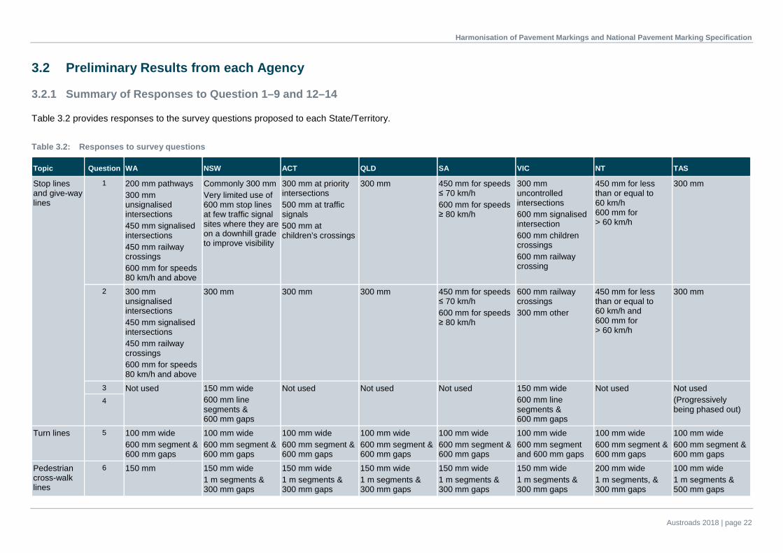
3.2.1 Summary of Responses to Question 1–9 and 12–14
Table 3.2 provides responses to the survey questions proposed to each State/Territory.
Table 3.2: Responses to survey questions
Topic Question WA NSW ACT QLD SA VIC NT TAS
Stop lines and give-way lines
1 200 mm pathways 300 mm unsignalised intersections 450 mm signalised intersections 450 mm railway crossings 600 mm for speeds 80 km/h and above
Commonly 300 mm Very limited use of 600 mm stop lines at few traffic signal sites where they are on a downhill grade to improve visibility
300 mm at priority intersections 500 mm at traffic signals 500 mm at children’s crossings
300 mm 450 mm for speeds ≤ 70 km/h 600 mm for speeds ≥ 80 km/h
300 mm uncontrolled intersections 600 mm signalised intersection 600 mm children crossings 600 mm railway crossing
450 mm for less than or equal to 60 km/h 600 mm for > 60 km/h
300 mm
2 300 mm unsignalised intersections 450 mm signalised intersections 450 mm railway crossings 600 mm for speeds 80 km/h and above
300 mm 300 mm 300 mm 450 mm for speeds ≤ 70 km/h 600 mm for speeds ≥ 80 km/h
600 mm railway crossings 300 mm other
450 mm for less than or equal to 60 km/h and 600 mm for > 60 km/h
300 mm
3 Not used 150 mm wide 600 mm line segments & 600 mm gaps
Not used Not used Not used 150 mm wide 600 mm line segments & 600 mm gaps
Not used Not used (Progressively being phased out)
4
Turn lines 5 100 mm wide 600 mm segment & 600 mm gaps
100 mm wide 600 mm segment & 600 mm gaps
100 mm wide 600 mm segment & 600 mm gaps
100 mm wide 600 mm segment & 600 mm gaps
100 mm wide 600 mm segment & 600 mm gaps
100 mm wide 600 mm segment and 600 mm gaps
100 mm wide 600 mm segment & 600 mm gaps
100 mm wide 600 mm segment & 600 mm gaps
Pedestrian cross-walk lines
6 150 mm 150 mm wide 1 m segments & 300 mm gaps
150 mm wide 1 m segments & 300 mm gaps
150 mm wide 1 m segments & 300 mm gaps
150 mm wide 1 m segments & 300 mm gaps
150 mm wide 1 m segments & 300 mm gaps
200 mm wide 1 m segments, & 300 mm gaps
100 mm wide 1 m segments & 500 mm gaps

Harmonisation of Pavement Markings and National Pavement Marking Specification
Austroads 2018 | page 23
Topic Question WA NSW ACT QLD SA VIC NT TAS
Replacement of dividing lines for multi-lane roads in urban areas
7 Agree Preference: 200 mm
Agree Preference 150 mm
Agree Preference: 150 mm
Agree Preference: 200 mm
Agree Preference: 200 mm
Agree Preference: 150 mm
Not specified Agree Preference: 150 mm
Tram, tramway and transverse lines
8 Line width: 100 mm Agreed to AS 1742.12:2017
Agreed to AS 1742.12:2017
Agreed to AS 1742.12:2017
Agreed to AS 1742.12:2017
Colour: Yellow No traffic lane in tram lanes Agreed to AS 1742.12:2017
Agreed to AS 1742.12:2017
Agreed to AS 1742.12:2017
Agreed to AS 1742.12:2017
Audio-tactile line markings
9 Width of raised rib: 100 mm dividing lines
100 mm separation lines
Not provided 80 mm centre barrier lines
100 mm dividing lines and lane lines
100 mm dividing lines, 100 mm bicycle lines
80 mm ± 2 mm centre barrier lines
Not provided
Width of raised rib: 150 mm edge lines
150 mm edge lines 150 mm abutting edge lines
150 mm edge lines 150 mm abutting edge lines
150 mm edge lines 150 mm ± 2 mm edge lines 250 mm longitudinal edge line for roads with sealed shoulder
150 mm edge lines
Length of raised rib in longitudinal direction: 60 mm ± 10 mm
60 mm ± 10 mm 60 mm ± 10 mm 50 mm ± 2 mm 50 mm 50 mm 50 mm ± 2 mm 50 mm
Height of raised ribs proud of pavement surface: 10 mm ± 2 mm
10 mm ± 2 mm 10 mm ± 2 mm 8 mm ± 2 mm 8 mm 8 mm edge lines & dividing lines, 5–6 mm bicycle lines
10 mm ± 2 mm 8 mm
Spacing of raised ribs on longitudinal direction: 250 mm ± 50 mm
250 mm ± 50 mm 250 mm ± 50 mm 250 mm ± 10 mm 200 mm 200 mm 250mm ± 10mm 200 mm
Slope angle of raised rib lead and trail faces: Approx. 45°
Approx. 45° Approx. 45°

Harmonisation of Pavement Markings and National Pavement Marking Specification
Austroads 2018 | page 24
Topic Question WA NSW ACT QLD SA VIC NT TAS
Wide-centreline treatments (WCLT) *width is measured from centre to centre
12 WCLT width: 1 m Lane width: 3.5 m Shoulder width: varies
WCLT width: 1 m Lane width: 3.5 m Shoulder width: 2 m; for an existing 11 m wide road a 1.5 m shoulder; for a sealed shoulder 1 m & an additional 0.5 m unsealed shoulder
Not used WCLT width: 1 m for posted speeds ≥ 90 km/h 0.8 m for posted speeds 70–80 km/h. 0.6 m for posted speed 60 km/h. Lane width: 3.25 m (all vehicles up to B-double); 3.50 m (type 1 road train); 3.75 m (type 2 road train) lane widths Shoulder width: ranges from 1.0–1.25–1.50–1.75–2.0 m depending on road type and lane width
WCLT Width: 1.05–1.2 m Lane Width: 3.3–3.5 m Shoulder Width: 0.5 m
Will adopt the Australian Standard when developed
Not used Not used

Harmonisation of Pavement Markings and National Pavement Marking Specification
Austroads 2018 | page 25
Topic Question WA NSW ACT QLD SA VIC NT TAS
Pavement arrows
13 Intersection pavement arrows (common types): AS 1742.2:2009
AS 1742.2:2009 (Figure B 46)
To be Advised AS 1742.2:2009 Use as per AS 1742.2:2009, detailed use case Figure B 6 and Figure B 7
AS 1742.2:2009, arrow length may be lengthened on high speed roads if desired
AS 1742.2:2009 AS 1742.2:2009
Intersection pavement arrows (special types): Australian Standard for double turn and U-turn (Figure 2.6: a, b). Oblique right turn arrow and right turn with U-turn arrow (Figure B 32).
Australian Standard (AS 1742.2:2009), instead of the 45° turn arrow a standard straight-ahead arrow offset at an angle is used for an offset turn situation (Figure B 47). Additionally, use the three way turn arrow (Figure B 32)
To be Advised AS 1742.2:2009 Use as (AS 1742.2:2009) detailed use case Figure B 8
AS 1742.2:2009 AS 1742.2:2009 AS 1742.2:2009, the U-turn arrow is only used where it is the only possible manoeuvre, where U-turns are allowed from the right-turn lane, right-turn arrows are supplemented with a ‘U-turn permitted’ sign, 45° arrow has been used at a small number of locations, sequential turns arrow has not been used anywhere
Lane change pavement arrows: AS 1742.2:2009
Australian Standard (AS 1742.2:2009) (Figure B 48)
To be Advised AS 1742.2:2009 Use as per AS 1742.2:2009, dimensions as per Figure B 9
AS 1742.2:2009 AS 1742.2:2009 Australian Standard is adopted although urban is denoted as below 60 km/h and rural is denoted as above 60 km/h. The urban type is not widely used as the majority of lane terminations in low speed areas are zip merge. Left hand versions have been used at ‘seagull’ style junctions where a left merge exists.

Harmonisation of Pavement Markings and National Pavement Marking Specification
Austroads 2018 | page 26
Topic Question WA NSW ACT QLD SA VIC NT TAS
Expressway exit lane arrows: AS 1742.2:2009, additional for straight through (Figure B 31).
Use AS 1742.2:2009 lane change or merge arrows (flip for direction options). When there is a combined exit/straight ahead lane the lane change arrow is attached with a straight ahead arrow
To be Advised AS 1742.2:2009 Use as per AS 1742.2:2009, dimensions as per Figure B 10
Australian Standard (AS 1742.2:2009)
Australian Standard (AS 1742.2:2009)
Only a small number of sites where these are used, AS 1742.2:2009 is adopted but only the trap lane and adjacent combined exit and through are marked, subsequent through lanes are not
Bike path/shared paths
14 New version of AS 1742.9:2000
New version of AS 1742.9:2000
New version of AS 1742.9:2000
New version of AS 1742.9:2000
New version of AS 1742.9:2000
New version of AS 1742.9:2000
New version of AS 1742.9:2000
New version of AS 1742.9:2000
Source: RAPMG, compiled by ARRB.

Harmonisation of Pavement Markings and National Pavement Marking Specification
Austroads 2018 | page 27
3.2.2 Summary of Responses – ATLM Installation Methods
In relation to Question 11 of the survey, responses were received from the Northern Territory, New South Wales, Australian Capital Territory, Queensland, Western Australia, South Australia and Tasmania. An international review of ATLM, and technologies regarding the maintenance and installation of ATLM (including approaches from New Zealand) is provided in Appendix C.2. This analysis was undertaken to support the development of techniques in Australia, and further investigate possible harmonisation of maintenance methods.
Northern Territory
The Northern Territory’s Guidelines for ATLM comprise:
• Site preparation: Immediately prior to application, remove all extraneous or loose material from areas where the thermoplastic material is to be applied. Prepare and prime areas as recommended by the manufacturer to ensure satisfactory adhesion of thermoplastic material.
• Application: Apply ATLM directly onto existing painted edge lines or centre double barrier lines. The height of the thermoplastic raised ribs is measured from the planed surface formed by the tops of the aggregate.
• Retroreflectivity: Immediately apply glass beads in accordance with AS/NZS 2009:2006 Type B to the surface of the molten thermoplastic material. The minimum rate to be retained on the thermoplastic material is 200 g/m2. Marking must achieve a minimum level of reflectivity of 350 mcd/lux/m2 at the time of application when tested in accordance with AS 4049.2:2005.
• Thermoplastics: Thermoplastic used for audio tactile pavement markings must comply with AS 4049.2:2005 but modified as follows
– Softening point: when determined in accordance with AS 2341.18:1992 the softening point shall be not less than 95 °C.
– Cold flow: When determined in accordance with AS 4049.2:2005, the cold flow shall be no more than 5% at 40 °C.
– Skid resistance: When tested in accordance with AS 4049.2:2005, at any time up to 3 000 000 vehicle passes, the skid resistance value of beaded un-profiled base material must be not less than 50 BPN (British Pendulum Number).
New South Wales
Two types of ATLM are used in NSW: type A and type B.
Type A is formed by mechanically screeding a conventional thermoplastic line and simultaneously applying transverse ribs of the same thermoplastic material at a regular interval. This type produces good audible and tactile effect (Figure B 49).
Type B is formed by extruding transverse ribs placed directly onto the road surface. This line has similar audible and tactile effects to Type A and avoids drainage problems. The spacing and configuration of ribs can be varied to suit any requirements, with 250 mm considered the optimum spacing (Figure B 51).
NSW also uses a different type of audio-tactile linemarking for special lane line application L2, where ceramic dots are used instead of painted lines. NSW is also investigating the milled pavement option (Ozrumble).
Australian Capital Territory
Due to the ACT being predominately urban. ATLM is not used due to noise complaints. It is noted, however, that if ATLM were to be installed, then the agency would follow the procedures used by NSW.

Harmonisation of Pavement Markings and National Pavement Marking Specification
Austroads 2018 | page 28
Queensland
ATLM shall be applied directly to existing painted edge lines or centre double barrier lines. ATLM shall not be applied at locations where edge line has not been marked (such as across narrow structures).
Where applied on existing painted lines, all extraneous or loose material shall be removed from areas where the material is to be applied immediately prior to the application of ATLM. Additionally, existing linemarkings shall be prepared and primed in accordance with the thermoplastic manufacturer’s recommendations, to ensure satisfactory adhesion of the thermoplastic material.
Where wide-centreline treatment (WCLT) has been installed, ATLM shall be installed abutting longitudinal linemarking.
During installation of a WCLT, ATLMs will be marked at a different time to the marking of the WCLT due to the application of different equipment for each marking type. In cases where a reseal of the pavement is scheduled shortly after the installation of the WCLT, the installation of the ATLM's may be deferred until after the next reseal.
Western Australia
Profile thermoplastic or cold applied plastic audio tactile ribs and waterborne paint longitudinal edge line shall be laid in accordance with MRWA Specification 604 (MRWA 2016) including the application of drop-on B-HR glass beads. Audio-tactile ribs shall be installed on the outside of the lane. WCLT is to be installed adjacent to a passing or overtaking lane.
WA is trialling audio-tactile centrelines and has agreed on the preferred treatment outlined in this report. This treatment uses continuous grey/black ribs on the centreline of the road and the line markings are installed on top of the ribs.
Where the sealed shoulder is less than 1 m wide the ribs are placed on top of the edge line. Where the sealed shoulder is 1 m or wider the ribs are placed outside the line. For WCLT the ribs are placed adjacent to the lines.
South Australia
A discontinuous thermoplastic style of ATLM is used in South Australia; surface preparation required before its installation. Other treatments which can be trialled, but require approval beforehand from the Manager Traffic Operations, are:
• rumble shoulders – where asphalt or concrete road shoulders have grooves either cut out or formed in them
• textured shoulders – where sealed shoulders use larger aggregate stone and texture to that of the pavement
• wide centred medians – where the ATLM is placed centrally.
Tasmania
Two types of ATLM are used in Tasmania.
• Type A (extruded transverse ribs directly onto road surface) – a painted line is applied over the ribs to improve retroreflectivity performance. Note that this is similar to the ‘Type B’ arrangement specified in the NSW comments.
• Type B – a thermoplastic base line followed by the placement of extruded transvers ribs onto the line (similar to the ‘Type A’ noted by NSW).

Harmonisation of Pavement Markings and National Pavement Marking Specification
Austroads 2018 | page 29
Due to road surfaces being primarily chip seals, the Type A (ribs only) line was found to have very limited lifespan. The Type B (ribs on base line) has very good performance both in terms of longevity and audible effect. While the initial application cost is significantly higher, the overall life cycle cost is reduced with some installations still operating satisfactorily in terms of audible performance after some six to eight years on lower volume roads.
3.2.3 Summary of Responses – Maintenance of ATLM
In relation to Question 10 of the survey, each of the agencies was also asked to provide information regarding the preferred method for the maintenance and removal of ATLM. Responses were received from Queensland, Victoria, Western Australia and Tasmania.
Queensland
ATLM are formed using extruded thermoplastics. These have varying durability across the state’s roads due to a number of factors, including: traffic volume, road surface temperatures, pavement condition and quality control effort at the time of installation. There are currently no guidelines for intervention levels for replacing old ATLMs, and there is no standard cost-effective procedure to remove old ATLMs available.
Victoria
ATLM requirements are specified in VicRoads’ Supplement to AS 1742.2:2009 (VicRoads 2015). VicRoads reported that the need to remove pavement markings should be avoided where possible. However, when required, high-pressure water blasting and grit blasting are the preferred methods of treatment, providing the most effective long-term solutions. High-pressure water blasting is the preferred method as this removes almost all of the marking and minimises the visibility of removed marking during sun glare, night or wet road conditions. Other methods of removal include:
• Blasting using carbonated soda also provides reasonable results; however, it is less effective than other methods of removal on some pavement marking materials such as cold applied plastic.
• Grinding, although effective, causes damage to the road surface and drivers can become confused trying to distinguish between a damaged area of pavement and a pavement marking under certain conditions.
• Strip sealing is a very effective method of removing pavement markings; however, its use should be limited to surfaces with a sprayed seal in low- to moderately-trafficked areas.
• Blacking out has a very limited life span and should only be considered as a temporary treatment based on assessing risks. However, blacking out with long-life materials may be the only option if the road surface is in a very poor condition, brittle, or has a crumbling surface.
Western Australia
MRWA Specification 604 (MRWA 2016) covers the installation and application methods for ATLM (see Section 3.2.2. This specification also covers the maintenance methods for these linemarkings.
Tasmania
Retroreflectivity intervention is typically provided with painted lines over the ATLM installation unless the audible performance has deteriorated, in which case the lines would be replaced with new ATLM. The typical method of removal is water-blasting unless prior to resealing where grinding may be permitted.

Harmonisation of Pavement Markings and National Pavement Marking Specification
Austroads 2018 | page 30
4. Agreed Harmonisation of Good Practice
4.1 Preferred Approaches to Linemarking Practice
Based on the responses to the questionnaire, a summary of the preferred approaches to linemarking practice is presented in Table 4.1.
Table 4.1: Summary of preferred approaches to linemarking practice
Topic Question number
Number of responses received
(out of 8) Preferred approach
Stop and give-way lines 1 8 Predominantly line width of 300 mm or 450 mm*
2 8 Lane width predominantly 300 mm*
3 8 Applied in NSW and VIC
4 8 Applied in NSW and VIC
Turn lines 5 8 100 mm width, 600 mm line segment, 600 mm gaps
Pedestrian cross-walk lines 6 8 Predominately line width of 150 mm
Replacement of dividing lines for multi-lane roads in urban areas
7 7 Majority of the states supported the change to a line width of 150 mm, with three states (SA, WA & QLD) preferring 200 mm
Tram, tramway and transverse lines
8 3 Agreed to adopt AS 1742.12:2017
Audio-tactile linemarkings 9 8 Line width: variable but commonly 150 mm Rib width: 50 mm or 60 mm Rib height: 8 mm or 10 mm Rib spacing: 200 mm or 250 mm Slope of raised rib: Approximately 45°
10 4 Variable results
11 6 Variable results
Wide-centreline treatments 12 8 Variable results
Pavement arrows, letters and numerals
13 7 Predominantly AS 1742.2:2009
Bike path/shared paths 14 2 Predominantly the new version of AS 1742.9:2000
* Although these are the preferred line widths, the cases in which they apply vary between each State. Source: RAPMG, compiled by ARRB.
4.1.1 Stop and Give-way Lines
A summary of the different line widths, scenarios and approaches for stop lines and give-way lines used by road agencies is presented in Table 3.2. The results for stop lines were variable as each road agency provided different scenarios with different line widths.
NSW, QLD, and TAS use a width of 300 mm for all stop lines. One exception is that NSW occasionally uses a width of 600 mm for stop lines located on a downhill grade in order to improve visibility.
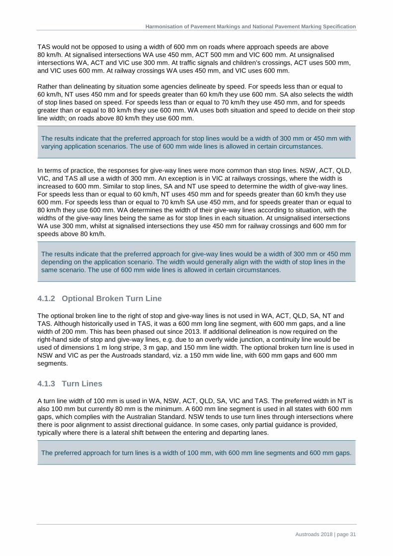
Harmonisation of Pavement Markings and National Pavement Marking Specification
Austroads 2018 | page 31
TAS would not be opposed to using a width of 600 mm on roads where approach speeds are above 80 km/h. At signalised intersections WA use 450 mm, ACT 500 mm and VIC 600 mm. At unsignalised intersections WA, ACT and VIC use 300 mm. At traffic signals and children’s crossings, ACT uses 500 mm, and VIC uses 600 mm. At railway crossings WA uses 450 mm, and VIC uses 600 mm.
Rather than delineating by situation some agencies delineate by speed. For speeds less than or equal to 60 km/h, NT uses 450 mm and for speeds greater than 60 km/h they use 600 mm. SA also selects the width of stop lines based on speed. For speeds less than or equal to 70 km/h they use 450 mm, and for speeds greater than or equal to 80 km/h they use 600 mm. WA uses both situation and speed to decide on their stop line width; on roads above 80 km/h they use 600 mm.
The results indicate that the preferred approach for stop lines would be a width of 300 mm or 450 mm with varying application scenarios. The use of 600 mm wide lines is allowed in certain circumstances.
In terms of practice, the responses for give-way lines were more common than stop lines. NSW, ACT, QLD, VIC, and TAS all use a width of 300 mm. An exception is in VIC at railways crossings, where the width is increased to 600 mm. Similar to stop lines, SA and NT use speed to determine the width of give-way lines. For speeds less than or equal to 60 km/h, NT uses 450 mm and for speeds greater than 60 km/h they use 600 mm. For speeds less than or equal to 70 km/h SA use 450 mm, and for speeds greater than or equal to 80 km/h they use 600 mm. WA determines the width of their give-way lines according to situation, with the widths of the give-way lines being the same as for stop lines in each situation. At unsignalised intersections WA use 300 mm, whilst at signalised intersections they use 450 mm for railway crossings and 600 mm for speeds above 80 km/h.
The results indicate that the preferred approach for give-way lines would be a width of 300 mm or 450 mm depending on the application scenario. The width would generally align with the width of stop lines in the same scenario. The use of 600 mm wide lines is allowed in certain circumstances.
4.1.2 Optional Broken Turn Line
The optional broken line to the right of stop and give-way lines is not used in WA, ACT, QLD, SA, NT and TAS. Although historically used in TAS, it was a 600 mm long line segment, with 600 mm gaps, and a line width of 200 mm. This has been phased out since 2013. If additional delineation is now required on the right-hand side of stop and give-way lines, e.g. due to an overly wide junction, a continuity line would be used of dimensions 1 m long stripe, 3 m gap, and 150 mm line width. The optional broken turn line is used in NSW and VIC as per the Austroads standard, viz. a 150 mm wide line, with 600 mm gaps and 600 mm segments.
4.1.3 Turn Lines
A turn line width of 100 mm is used in WA, NSW, ACT, QLD, SA, VIC and TAS. The preferred width in NT is also 100 mm but currently 80 mm is the minimum. A 600 mm line segment is used in all states with 600 mm gaps, which complies with the Australian Standard. NSW tends to use turn lines through intersections where there is poor alignment to assist directional guidance. In some cases, only partial guidance is provided, typically where there is a lateral shift between the entering and departing lanes.
The preferred approach for turn lines is a width of 100 mm, with 600 mm line segments and 600 mm gaps.
Harmonisation of Pavement Markings and National Pavement Marking Specification
Austroads 2018 | page 32
4.1.4 Pedestrian Crosswalk Guidelines
A line width of 150 mm, with 1 m line segments and 300 mm gaps, as per AS 1742.14:2014, is used by WA, NSW, ACT, QLD, SA, and VIC. A width of 200 mm is used in the NT with a 1.0 m line segment and 300 mm gaps. In TAS the current practice is 100 mm line width with 100 mm line segments and 500 mm gaps. TAS has indicated possible consideration towards changing their guidelines to a 150 mm line width with 1 m segments and 300 mm gaps as per AS 1742.14:2014. SA only adopted their current approach in 2015; previously they used 600 mm line segments with 600 mm gaps and a line width of 150 mm.
The preferred approach for pedestrian cross-walk lines is a line width of 150 mm with 1 m line segments and 300 mm gaps. Further agreement may be required.
4.1.5 Replacement of Dividing Lines for Multi-lane Roads
Opinion was sought from all agencies regarding:
• using single barrier lines (unbroken separation line) or double two-way barrier lines to replace the dividing lines for multi-lane undivided roads, and special-purpose lines for short, sharp curves or crests
• ascertaining what the width of this line should be.
In WA, the line widths on multi-lane roads are between 150 and 200 mm, but the preferable change for WA would be a width of 200 mm. The 200 mm width was agreed by QLD as it uses the same amount of paint but has 30% less width than dual solid double barrier lines. This width was also agreed by SA. A width of 200 mm has been historically adopted in TAS; however, trails of 150 mm width have been met favourably by contractors due to less width changes per site. States preferring the 150 mm width were NSW, ACT, VIC and TAS. The ACT has already adopted a width of 150 mm and 150 mcd reflectivity. NSW prefers to apply the linemarkings in one pass and 200 mm would be too wide for this in practice. VIC’s preference is 150 mm because they believe that 200 mm is too wide for this type of line. No response was received from the NT.
All states agreed to change the width of dividing lines for multi-lane undivided roads and special purposes lines for short, sharp curves or crests with single barrier lines (unbroken separation). Three of the seven states agreed to 200 mm, while the other four felt that a line width of 150 mm was more appropriate.
4.1.6 Tram, Tramway and Transverse Lines
Responses were received from WA, SA and VIC. WA specified that their preferred line width for tram lines was 100 mm. SA specifies that their tram lines be yellow in colour. They do not have joint tram/traffic lanes (i.e. vehicles do not drive in the tram lane). All states agreed to adhere to the specifications outlined in AS 1742.12: 2017 for tram lines and tram lanes.
At the Roads Australia (2015a) meeting, it was noted that, in Victoria, there was a need to consider and consolidate different line types used for the different lane types. VicRoads undertook a full review of their linemarking supplement with the intention of consolidating the number of lines used. Replacing the 6 m line segment with 6 m gaps yellow lane line pattern with a more widely used pattern (such as 9 m line segments with 3 m gaps) was discussed at the Roads Australia and RAPMG meetings. VicRoads have since found that the current tram linemarking configuration is used by Yarra Trams in Victoria to assist drivers in gauging distances from other moving vehicles and stationary objects. The 6 m by 6 m configuration has been specifically included in the revised AS 1742.12:2017 and will remain as is.

Harmonisation of Pavement Markings and National Pavement Marking Specification
Austroads 2018 | page 33
Thirty different line types are used in VIC, compared to 13 in the Australian Standard. This is because the list includes additional tram lines, bicycle lines, snow lines, no parking lines, reversible traffic lines etc. (i.e. Victoria have combined lines from AS 1742.2:2009, AS 1742.9:2000, AS 1742.12:2017, etc. in the one table to make it easier for practitioners). However, if all of the general longitudinal lines are as per the Australian Standard then Victoria will be consistent with other states (with the exception of a narrow intersection approach treatment and a specific reversible traffic lane treatment – there are only two in Victoria).
The preferred approach by all states is to adhere to AS 1742.12: 2017.
4.1.7 Audio-tactile Linemarkings (ATLM)
The results indicated that QLD, SA, VIC, NT and TAS use a length of raised rib in the longitudinal direction of 50 mm, whereas WA and NSW use 60 mm. QLD, SA, VIC and TAS also use a height of raised rib proud of the pavement of 8 mm, with an exception on bicycle lanes in VIC, where 6 mm is used. WA, NSW and NT use a height of 10 mm. WA, NSW, QLD and NT use a spacing of raised ribs in the longitudinal direction of 250 mm. All other States use a spacing of raised ribs in the longitudinal direction of 200 mm. Three states responded to the question regarding the slope angle of the raised rib on the lead and trail faces. This was consistent, with the angle being approximately 45°.
Four responses were provided regarding the installation and formation methods for ATLM. These were variable and have been summarised in Section 3.2.2. Six of the eight jurisdictions provided responses on the maintenance method for the ATLM. These responses are summarised in Section 3.2.3.
The following is a summary of the preferred dimensions for ATLM:
• Width of raised rib: variable but commonly 150 mm
• Length of raised rib in longitudinal direction: 50 mm or 60 mm
• Height of raised ribs proud of pavement surface: 8 mm or 10 mm
• Spacing of raised ribs in longitudinal direction: 200 mm or 250 mm
• Slope angle of raised rib lead and trail faces: approximately 45°.
4.1.8 Wide-centrelines Treatments (WCLT)
The responses regarding the dimensions of audio-tactile linemarkings indicated a variety of practices. A line width of 150 mm was used for edge lines by SA, NSW, ACT, QLD, VIC, NT, and TAS, and WA will adopt 150 mm in the near future. A line width of 100 mm is used for dividing line/centrelines/separation lines by WA3 and SA. NSW, VIC and QLD use a line width of 80 mm for centre barrier lines and a line width of 150 mm on abutting edge lines and centrelines. VIC use a width of 100 mm for bicycle lane lines. NT use a width of 80 mm for centre barrier lines, similar to QLD. SA use 100 mm for all other dividing lines except for multi-lane undivided roads, where a 200 mm wide line is used.
3 Between diving lines/centrelines/separation lines WA uses a width of 1 m. See Section 4.1.7 for more information on wide-centreline
treatments.

Harmonisation of Pavement Markings and National Pavement Marking Specification
Austroads 2018 | page 34
WCLT has not yet been adopted by the ACT, NT and TAS. All states that have adopted this road marking use a width of 1 m from centre of line to centre of line of two adjacent parallel lines, excluding SA which uses a width of 1.05–1.2 m. There are provisions for varying the width in order to provide further separation between on-coming vehicles when it is deemed necessary. QLD determine the width of the WCLT on the basis of speed: 1 m is used for speeds above 90 km/h, 0.8 m for a posted speed of 70–80 km/h, and 0.6 m for a posted speed of 60 km/h. A 3.5 m lane width either side of a WCLT is used in WA, NSW and ACT. In SA, 3.5 m is the preferred lane width; however, there are also currently roads with 3.3 m wide lanes. The lane width in QLD varies depending on the type of vehicle. For vehicles up to B-double, the lane width is 3.25 m, for type 1 road trains it is 3.5 m, and for type 2 road trains it is 3.75 m. VicRoads is currently adopting the Austroads Guide to Road Design Part 3 (Austroads 2008–2017) and Austroads Guide to Traffic Management Part 10 (Austroads 2015–2018) for WCLT.
Although the lane and shoulder widths vary between states, the preferred approach for WCLT is further discussed in Section 4.2. WCLT will be included in AS 1742.2:2009.
The results indicate that the preferred approach is to use a width of 1 m from the centre of a line to the centre of an adjacent parallel line. However, there are provisions to vary the width in order to provide further separation between on-coming vehicles where it is deemed necessary.
4.1.9 Pavement Arrows
The most commonly used materials used for pavement arrows are either thermoplastics or cold applied plastics. All pavement arrows in WA are installed using thermoplastic (beads and anti-skid). NSW also uses thermoplastic arrows with beads and anti-skid thermoplastics; they are mainly pre-formed, although some are screeded. In TAS thermoplastic (beads and skid) is used for pavement arrows on higher-volume roads; all other road markings are also typically thermoplastic. On lower-volume roads, TAS uses paint for their pavement arrows; typically, all other road markings are also paint. However, SA uses cold applied plastics for their pavement arrows, although there has been a trial of thermoplastic at one intersection.
Prior to 2014 NSW had their own arrow designs which differed in size and shape to the AS 1742.2:2009 arrows. Therefore, the NSW network has a combination of old and new styles and it will remain this way until the transition is complete. Arrows are generally replaced with the AS 1742.2:2009 style during resurfacing projects.
All states have adopted AS 1742.2:2009 for common intersection pavement arrows. SA and NSW have used cases shown in Figure B 7 and Figure B 46 respectively. VIC also uses AS 1742.2:2009; however, the length of the pavement arrow may be lengthened on high-speed roads if desired. This is shown in Figure 4.1 and Figure 4.2.
For special type intersection pavement arrows, the majority of states have adopted AS 1742.2:2009. This includes WA, NSW, QLD, SA, VIC, NT, and TAS. However, WA is not using the 45° arrow and the sequential arrow; they are only using AS 1742.2:2009 for double turns and U-turns. WA has also implemented an oblique right-turn arrow and right turn with U-turn arrow (Figure B 32). NSW also differ from AS 1742.2:2009 for the 45° turn arrow, using instead a standard straight-ahead arrow but offset at an angle for an offset turn situation (Figure B 47). NSW and WA use a three-way straight, left and right-turn arrow for some multi-lane intersections (Figure B 32). TAS only uses the U-turn arrow where it is the only possible manoeuvre. Where U-turns are allowed from the right-turn lane, the right-turn arrows are supplemented with a ‘U-turn permitted’ sign. TAS also does not use the sequential turn arrow. SA has mainly adopted AS 1742.2:2009; however, there are some differences which are summarised as a detailed use case in Figure B 6.
For lane change pavement arrows the majority of states have adopted AS 1742.2:2009. However, in TAS the urban speed is denoted at below 60 km/h and the rural speed is denoted as above 60 km/h. The urban type is not commonly used in TAS as the majority of lane terminations in low-speed areas are zip merge. Left-hand versions of these pavement arrows have also been adopted in TAS at ‘seagull’ style junctions where a left merge exists. Specific dimensions for lane change pavement arrows in NSW and SA are provided in Figure B 48 and Figure B 9 respectively.

Harmonisation of Pavement Markings and National Pavement Marking Specification
Austroads 2018 | page 35
Figure 4.1: Length of pavement arrows
Source: VicRoads.

Harmonisation of Pavement Markings and National Pavement Marking Specification
Austroads 2018 | page 36
Figure 4.2: Length of pavement arrows
Source: VicRoads.
For expressway exit lane pavement arrows all states except NSW have adopted AS 1742.2:2009. NSW does not use AS 1742.2:2009 for expressway exit lane pavement arrows, using instead AS 1742.2:2009 for lane change pavement arrows (flipped for direction). Where there is a combined exit/straight ahead lane, the lane change arrow is attached to a straight-ahead arrow, in the interests of reducing the number of arrow types. This is detailed in Figure B 48. They would, however, find it acceptable to adopt the AS 1742.2:2009 expressway exit lane arrows as outlined in Figure 2.8. The use of expressway exit lane arrows in SA is detailed in Figure B 10. There are only a small number of sites in TAS where this arrow type is used; only the trap lane and adjacent combined exit and through lane are marked, subsequent lanes are not.
NSW will continue to transition towards the AS 1742.2:2009 arrows; however, it would also consider alternatives for harmonisation.
The preferred approach is to move towards AS 1742.2:2009 for all arrow types in thermoplastic (beads and anti skid), or cold applied plastics.

Harmonisation of Pavement Markings and National Pavement Marking Specification
Austroads 2018 | page 37
In terms of the materials used to form pavement arrows, TAS generally use thermoplastic (beads and skid) on higher-volume roads (where other markings are typically thermoplastic), or paint on lower-volume roads (where paint markings are used). Most thermoplastic applications are stencilled and screeded; however, preform melt is also used. Pre-formed pavement tape arrows were trialled but had limited success. The use of cold applied plastics is being considered as a future option. Whilst SA use cold applied plastic, and are trialling preformed thermoplastic, NSW currently use pre-formed (and some screeded) thermoplastic (beads and anti-skid).
4.1.10 Pavement Letters and Numerals
Prior to this harmonisation project being undertaken, it was determined by RAPMG that all pavement letters and numerals had been harmonised and all adhere to AS 1742.2:2009.
The preferred approach is to use AS 1742.2:2009 for all pavement letters and numerals as defined in Figure 2.9.
4.1.11 Bike Paths/Shared Paths
Shared paths are used in various states. The width of a shoe print on a marked pedestrian way is proposed to be either 80 mm or 100 mm. The width of all other line types is proposed to be the width outlined in the new version of AS 1742.9:2000 which is currently under review and due to be sent out for ballot in March 2018. The following dimensions are those outlined in the new version of the standard.
It has been proposed that stop and give-way lines for bike path/shared paths will be 200 mm wide. Furthermore, it has been proposed that longitudinal pavement markings for bike paths/shared paths will be 80 mm wide, specifically:
• edge line – a continuous line at the edges of the path, 80 mm wide
• unbroken separation line – a continuous line down the middle of the path, 80 mm wide
• broken separation line – a 1 m line with a 3 m gap down the middle of the path, 80 mm wide.
All of these markings will include surface applied glass beads and have a skid resistance of greater than 45 British Pendulum Number (BPN) or equivalent.
The preferred approach is to use the new version of AS 1742.9:2000 to be sent out for ballot in March 2018.
4.2 Justification for the Move to Preferred Markings
A summary of the proposed line types for harmonisation proposed by the RAPMG is shown in Figure 4.3. It is noted that LL2 lane lines could all remain at 100 mm wide to distinguish them from all other lines such as edge and outline lines.

Harmonisation of Pavement Markings and National Pavement Marking Specification
Austroads 2018 | page 38
4.2.1 Proposed Line Types
Figure 4.3: Proposed line types
Notes: • DL2 – SA will continue to use 200 mm. • LL2 – SA all lanes to remain at 100 mm. • CL – width to tie into the line it follows if this line is not also 150 mm. Source: RAPMG.

Harmonisation of Pavement Markings and National Pavement Marking Specification
Austroads 2018 | page 39
4.2.2 Stop and Give-way Lines
The width of a stop and a give-way line in AS 1742.2:2009 is 300 mm. This also applies to AS 1742.7:2016 (Railway Crossings), AS 1742.10:2009 (Pedestrian Control and Protection) and AS 1742.14:2014 (Traffic Signals) – as summarised in Section 2. AS 1742.14:2014 specifies a minimum width for traffic signals of 300 mm, a preferred width of 450 mm. If the 85% speed is 80 km/h or more, then it is recommended that the width be increased to 600 mm. MRWA has adopted this, including retroreflectivity and skid resistance.
Most states are using line widths of either 300 mm, 450 mm and 600 mm or all of them. The predominate approach for both stop lines and give-way lines was 300 mm or 450 mm for speeds below 80 km/h and 600 mm for speeds above 80 km/h. As these widths comply with AS 1742.2:2009, it has been determined that they will remain the same.
According to the RAPMG, the standard width for stop lines and give-way lines shall be 300 mm, increasing to 450 mm at signalised crossings, rail crossings and children’s crossings, and 600 mm for speeds above 80 km/h, including rail crossings. Furthermore, all stop and give-way lines should be retroreflective and have a minimum skid resistance of 45 BPN or equivalent.
The results of the questionnaire indicate that NT uses the 450 mm and 600 mm specification, maintaining 450 mm for the specified 300 mm situations. SA uses their current standard for stop and give-way lines which is 450 mm and 600 mm (see Table 3.2). ACT currently uses 500 mm at traffic signals and children’s crossings/school crossings, but have agreed to move towards 600 mm.
4.2.3 Turn Lines
The current Australian Standard (AS 1742.14:2014) recommends that the preferred width for turn lines is 100 mm, with 600 mm line segments and 600 mm gaps. This concurs with the preferred approach from the matrix; therefore, the harmonised practice for turn lines should be as above.
4.2.4 Pedestrian Cross-walk Lines
It is recommended in AS 1742.14:2014 that pedestrian crosswalk lines should be 150 mm wide, with 1 m line segments and 300 mm gaps. This concurs with the preferred approach in the matrix; therefore, the harmonised practice for pedestrian crosswalk lines should be as above.
4.2.5 Replacement of Dividing Lines for Multi-lane Roads in Urban Areas
All states agreed that dividing lines for multi-lane undivided roads and special-purpose lines for short, sharp curves or crests should be replaced with single barrier lines (unbroken separation). As there is a majority preference towards a width of 150 mm, RAPMG suggest that 150 mm should be the preferred line width. However, SA has indicated that they do not want to harmonise to 150 mm and would prefer to remain at 200 mm; hence RAPMG suggest that an allowance be given for 200 mm.
4.2.6 Tram, Tramway and Transverse Lines
A visual description of the preferred tram and tramway lines as proposed for harmonisation is shown in Figure 4.4. This proposal is based on the specification of tram lines and tramway lines in Victoria. The RAPMG have indicated that AS 1742.12:2017 includes line markings for trams and all States are in agreement (however, AS 1742.12:2017 does not include the widths of the lines which will be reviewed in AS 1742.2:2009). As can be seen in Figure 4.4, RAPMG are in agreement that tram lines be added as a separate category to the other lines in the Australian Standards.

Harmonisation of Pavement Markings and National Pavement Marking Specification
Austroads 2018 | page 40
Figure 4.4: Proposed tram, tramway and transverse lines
Source: RAPMG and VicRoads Supplement.
4.2.7 Audio-tactile Linemarkings
The RAPMG acknowledges that most or all road agencies use audio-tactile linemarking (ATLM) for edge lines and centre lines including wide-centreline treatments. It is suggested that AS 1742.2:2009 should include a short section on ATLM and possibly wide-centreline treatments.
MRWA uses audio-tactile edge lines as shown in Figure B 28 and Figure B 29. Additionally, some of the other road agencies use just ribs similar to Figure B 30. It is understood that there may be different dimensions, spacing and heights for the ribs around Australia and New Zealand.
It is proposed that only APAS-approved B-HR, C-HR and D-HR (with appropriate coatings) be used for the formation of the ATLM thermoplastics, and not B, C, and D type beads as the cost increase is minimal and the retroreflectivity is significantly higher which may result in longer service life.
From the matrix it has been determined that the specifications outlined in Table 4.1 for edge lines, dividing/separation lines and wide-centreline treatments are the optimal and predominant specifications for ATLM. These specifications will be reviewed and considered for the generation of the Australian Standard for ATLM.
TRAM AND TRAMWAY LINES (Traffic Lane with Adjacent Tram Track)
(b) Full-Time or Part-TimeTram Line
(d) Continuity Line forPart-Time Tram Line
(c) Tramway
WIDTHmm
100100100
These lines are covered in AS1742.12 Bus, Transit and Truck Lanes
Yellow
100
6m 6m 6m(a) Broken Type
Traffic lane with tramtracks(ie. no lane use restrictions)
Yellow
YellowCan be 150 forFull Time
150
1m 3m 1m 3m 1m 3m 1m
Yellow
TR 3
TR 1
TR 2
TR 4
100
DIVIDING LINES
(b) Stop Line
WIDTHmm
(a) Give Way Line Standard Width
Standard Width
GW
SL 300
TRANSVERSE LINES
300
600mm stripe and gap
At Rail Crossingsand Slip Lanes atTraffic Signals
450
Where ApproachSpeeds are 80km/hand Above
600
At Traffic Signals,Rail Crossings andChildren's Crossings
450
Where ApproachSpeeds are 80km/hand Above
600
Varies

Harmonisation of Pavement Markings and National Pavement Marking Specification
Austroads 2018 | page 41
Information on the preparation of a draft specification for longitudinal pavement marking has commenced and some information is provided in Section 5.1. The specification for longitudinal pavement markings is a performance type specification, containing the requirements for the initial, medium-term and long-term performance of longitudinal pavement markings. This specification will also outline methods for the maintenance of ATLM, including the appropriate intervention levels. These maintenance methods and intervention levels will be based of international research summarised in Appendix C. A draft of the longitudinal pavement marking specification has been included in Appendix D.
4.2.8 Wide-centreline Treatments
With respect to wide-centreline treatments, the RAPMG are interested in the widths of lines used, and whether these correspond to the ATLM specifications. It is intended that these will be developed into the new Australian Standards, rather than harmonising the specification of the actual wide-centreline treatments. Wide-centreline treatments (WCLT) have been adopted and are used by many road agencies. Their general use case is on double two-way barrier (see Figure 4.6), double one-way barrier and broken separation lines that are 100 mm wide and generally 1 m apart measured from centre to centre of the lines. The ribs are installed inside the double two-way barrier, double one-way barrier and broken separation lines. They are normally applied on roads with a speed limit of 90 km/h and above to reduce head on crashes. In their use case, the lane width can vary between 3.25 m and 3.5 m, with 3.5 m the preferred width. The ribs used can be made from thermoplastic or cold applied plastics and are normally white. The preferred specifications for the ribs themselves mimic the specifications for ATLM used on edge lines (Table 4.2 and Figure 4.5).
Table 4.2: Audio-tactile linemarking preferred specifications for edge line and dividing/separation line
Specification Edge line and WCLT Dividing/separation line
Width of the raised rib 150 mm 100–150 mm
Length of raised ribs (in longitudinal direction)
60 mm ± 10 mm * 60 mm ± 10 mm *
Height of raised ribs, proud of pavement surface (excluding surface applied B-HR beads)
10 mm ± 2 mm ** 10 mm ± 2 mm **
Spacing of raised ribs (in longitudinal direction)
250 mm ± 50 mm *** 250 mm ± 50 mm ***
Slope angle of raised rib lead and trail faces
Leading edge 45° Leading edge 45°
Notes • ATLM (edge line) is a fatigue countermeasure to prevent run-off-road crashes
• Most road agencies use some form of ATLM
• ATLM ribs can be thermoplastic or cold applied plastic
• ATLM ribs are normally white
• ATLM (dividing/separation line) is a fatigue countermeasure
• Some road agencies use some form of ATLM (dividing/separation line)
• ATLM ribs can be thermoplastic or cold applied plastic
• ATLM ribs for dividing/separation lines can be white or grey (white on the line or grey between the lines)
* Minimum rib length: 50 mm. ** Minimum rib height: 8 mm ± 2 mm. *** Minimum rib spacing: 200 mm. Notes: There are three different types of ATLM for edge lines:
• ribs on top of the 150 mm edge line (when the sealed shoulder is less than 1.0 m) • ribs on adjacent to the 150 mm edge line (when the sealed shoulder is 1.0 m or more) • ribs only – no edge line.
± has been applied in order to allow for variation in the preferred markings.

Harmonisation of Pavement Markings and National Pavement Marking Specification
Austroads 2018 | page 42
Figure 4.5: Edge line advancement audio-tactile rib diagram
Source: Main Roads Western Australia.
Figure 4.6: Double two-way barrier line and adjacent audio-tactile ribs
Source: Main Roads Western Australia.

Harmonisation of Pavement Markings and National Pavement Marking Specification
Austroads 2018 | page 43
4.2.9 Pavement Arrows
The current Australian Standard (AS 1742.2:2009) is discussed in Section 2.1.10. All states have agreed to either continue to use AS 1742.2:2009 or to transition towards using AS 1742.2:2009 for common types of intersection pavement arrows. In Victoria it is intended that common types of intersection pavement arrows may be lengthened on high-speed roads if desired. NSW has slight alterations to AS 1742.2:2009 which are detailed in Figure B 46.
All States have agreed to use AS 1742.2:2009 as a basis for special type intersection pavement arrows. All states have also agreed to adopt AS 1742.2:2009 as a basis for lane change pavement arrows. All states have agreed to adopt AS 1742.2:2009 for expressway exit lane pavement arrows. This is only a basis, as there are some minor differences to the Australian Standard in some jurisdictions. These are summarised in Section 4.1.9.
4.2.10 Pavement Letters and Numerals
Prior to this harmonisation project being undertaken, it was determined by RAPMG that all pavement letters and numerals had been harmonised and all adhere to AS 1742.2:2009. Therefore, the agreed approach for pavement letters and numerals is that which is denoted by Figure 2.9.
4.2.11 Bike Paths/Shared Paths
In addition to the linemarkings which were harmonised, as part of the development of this report and specification, the RAPMG Group also discussed linemarkings on shared paths, specifically cycleway lines. The agreed cycleway lines are shown in Figure 4.7. The only issue for thermoplastic linemarkings being used on shared paths is for the width of a shoe print on a marked pedestrian way, as shoes are expensive to print. Harmonisation of the width of the shoe was therefore recommended to be either 80 mm or 100 mm.
Additionally, longitudinal pavement markings and stop and give-way lines for bike paths/shared paths will be included in AS 1742.2:2009 (Traffic Control Devices for General Use), when it is next reviewed.
It has been agreed that stop and give-way lines for bike paths/shared paths will be 200 mm wide. Furthermore, it has been agreed that longitudinal pavement markings for bike paths/shared paths will be 80 mm wide, specifically:
• edge line – a continuous line at the edges of the path 80 mm wide
• unbroken separation line – a continuous line down the middle of the path 80 mm wide
• broken separation line – a 1 m line with a 3 m gap down the middle of the path 80 mm wide.
All of these markings will include surface applied glass beads and have a skid resistance of greater than 45 BPN or equivalent.

Harmonisation of Pavement Markings and National Pavement Marking Specification
Austroads 2018 | page 44
Figure 4.7: Cycleway lines for bike paths/shared paths
Source: Main Roads Western Australia.
4.2.12 Other Line Types
Prior to the collation of this detailed report, agreement by the RAPMG was achieved regarding the harmonisation of edge lines and continuity lines. However, these have not been covered in detail within this report. All states have agreed to adopt 100 mm or 150 mm wide (minimum) edge lines, depending on the line type that the continuity line is linked to. Furthermore, it has been agreed that these lines should be replaced when retroreflectivity falls to 150 mcd. All states have also agreed that continuity lines need to match the width used for the associated edge line. This would generally be increased to 200 mm on motorways/expressways. The continuity line should be the same width as per the edge line; therefore, if a 150 mm edge line is used then a 150 mm continuity line to also to be used. Similarly, if 200 mm edge lines are used on motorways then a 200 mm continuity line is to be used.
4.3 Agreed Approaches Table 4.3 summarises the RAPMG’s agreed approaches for harmonisation.

Harmonisation of Pavement Markings and National Pavement Marking Specification
Austroads 2018 | page 45
Table 4.3: Agreed approaches for harmonisation
Type Agreement Agreed by
Stop lines 300, 450 and 600 mm Widths harmonised as per AS 1742.2:2009 but applications of these widths can vary
All States have agreed to the general widths but have varying applications
Give-way lines 300, 450 and 600 mm Widths Harmonised as per AS 1742.2:2009 but applications of these widths can vary
All states have agreed to the general widths but have varying applications
Turn lines 100 mm wide, with 600 mm line segments and 600 mm gaps
All states
Pedestrian cross-walk lines 150 mm wide, with 1 m line segments and 300 mm gaps All states
Replacement of dividing lines for multi-lane roads in urban areas
Agreed change 150 mm, with allowance for increase to 200 mm
All states
Tram, tramway and transverse lines
Approaches shown in Figure 4.4 100 mm for all tramlines, except for continuity for part-time tram line which is 150 mm Transverse lines for give-way and stop lines and the same as regular give way lines and stop lines
All states
Audio-tactile linemarking Two approaches summarised in Table 4.2 Agreed by NSW, WA, SA
Wide-centreline treatment To match the width of the ATLM approach
Pavement arrows Australian Standard AS 1742.2:2009 with additions and alterations outlined in Section 4.2.9
All states
Bike paths/shared paths Approaches shown in Figure 4.7 Width of stop and give-way lines: 200 mm Width of longitudinal lines: 80 mm
All states
Source: RAPMG, compiled by ARRB.
RAPMG has also sought harmonisation of edge lines and continuity lines; however, this is outside the scope of this report. All states have agreed to be consistent and adopt 100 mm or 150 mm wide (minimum) edge lines (depending on the width of the line the continuity line is tying into) with a minimum of 150 mcd. All states have also agreed that continuity lines will match the width of edge lines.
4.4 ATLM Experimental Testing
There are a number of experimental tests/trials currently being conducted across Australia addressing audio-tactile linemarkings. These include the testing the effects of the environment on the condition of the thermoplastics, such as cracking as a result of increased and decreased temperatures. This section provides an overview of such testing in the Northern Territory, Victoria, New South Wales and Western Australia.
4.4.1 Northern Territory
It is recognised that temperature (frost or high temperatures) has a negative impact on different grades of thermoplastics for audio-tactile linemarkings. There is currently a trial being undertaken on the application of cold applied plastic, including an assessment of the cracking of these materials due to changes in temperature. The results of this trial are expected to be made available in 2018.

Harmonisation of Pavement Markings and National Pavement Marking Specification
Austroads 2018 | page 46
4.4.2 Victoria
The VicRoads mass action Audio Tactile Centre Line (ATCL) marking program involves the installation of audio-tactile devices on high-speed undivided rural roads across Victoria. The objective of the program is to reduce the risk of fatal and serious injuries as a result of a run-off-road or head-on crash in the most efficient way. It is not feasible to address run-off-road and head-on crash risk through other infrastructure treatments on these roads.
The program is targeting up to 4400 km of the low- to medium-volume arterial road network across Victoria. Installation has commenced across north east and eastern Victoria, where a continuous black audio-tactile line is being installed on the centreline and edge line where possible. To date, over 750 km has been completed (personal communication VicRoads SSRIP team).
4.4.3 New South Wales
Thermoplastic ATLM installed on concrete pavements was found to be lifting. A trial is being undertaken using cold applied plastic (CAP), and the results indicate that this is performing well.
4.4.4 Western Australia
MRWA is undertaking a trial of CAP ATLM (approximately 6 km of edge lines only) on Forrest Highway about 40 km north of Bunbury. This was installed in early May 2017. MRWA will also undertake a trial of CAP ATLM edge lines on Neerabup Road between the Freeway and Wanneroo Road.
Currently, five trial sites of ATLM centreline markings (white and grey thermoplastic ribs) have been set up on the York-Merredin Road, about 150 km east of Perth. The work was completed in early May 2017 and various options are being evaluated. The trials indicate that grey ribs give the appearance of a ‘removed line’ at night; however, they provide good audio-tactile responses. Unlike the edge line, they do not provide additional forward delineation or wet weather benefits; the linemarking is consistent with what is on the network. It is recognised that it may be expensive to install both grey and white audio-tactile ribs (Main Roads Western Australia unpublished). Further information on this trial has been included in Appendix B.3.1. MRWA’s preferred treatment is to provide ribs on the centreline and then install the linemarking on top of the ribs.
A further trial will be undertaken on Great Eastern Highway east of Northam. The trial will assist in determining the audio-tactile centreline marking treatment for Great Eastern Highway from The Lakes to Northam.
Wide-centreline treatments (1 m wide) of audio-tactile edge lines and audio-tactile broken separation lines, double one-way and double two-way barrier lines using white thermoplastic ribs are being undertaken on two roads on an approximate 10 km long section on the Coalfields Highway south of Perth and on about 20 km of the Great Northern Highway north of Perth. A public perception survey will be undertaken on a 10 km section of the Great Eastern Highway (Batty Bog).

Harmonisation of Pavement Markings and National Pavement Marking Specification
Austroads 2018 | page 47
5. Conclusions and Recommendations
5.1 Criteria of Clauses
Rather than a single national specification, this project has resulted in a series of clauses setting out the key criteria relating to the provision and maintenance of linemarkings (Appendix D). This is due to the fact that each state writes specifications differently. The proposal is to specify only APAS-approved B-HR, C-HR and D-HR type beads and no longer specify B, C and D type beads as the cost increase is minimal and retroreflectivity is significantly higher. This may result in longer life lines. This section therefore seeks to provide clauses referring to key criteria that can be inserted into each state’s specification.
The preparation of a draft specification for longitudinal pavement marking by the RAPMG has commenced. The specification for longitudinal pavement markings is a performance type specification, containing the requirements for the initial, medium-term and long-term performance of longitudinal pavement markings. This specification does not include transverse and other pavement markings. The specification provides the minimum requirements for the supply, installation and maintenance of road longitudinal pavement markings and audio tactile pavement marking (RAPMG 2018).
This specification sets out the requirements for the supply and application of longitudinal pavement marking material including water-borne paint, thermoplastic, two-part cold applied plastic, glass beads, temporary pavement markers (flaps) and preformed pavement marking tape. It also sets out the requirements for the supply and application of longitudinal pavement markings for works such as the:
• installation of markings on new roads and for revised traffic schemes
• reinstatement of markings after road works
• maintenance of markings (e.g. marking over existing markings).
A draft of the longitudinal pavement marking specification is shown in Appendix D.
In the future, as part of the harmonisation process, there is an opportunity to develop an Australian Pavement Marking Manual.
5.2 Challenges to Achieving a National Specification
In 2014, the Roads Australia Board Workshop identified potential technical specifications that could be harmonised. A series of workshops were conducted in WA, NSW, QLD and VIC, at which over 400 attendees discussed the current status of their respective jurisdictions and identified opportunities to harmonise specifications and improve the economic effectiveness of harmonisation across all parties (Roads Australia 2015a).
These workshops therefore focussed on:
• practicality
• value for money
• alignment with best practice.
Pavement marking was identified as a priority. On the basis of this it was determined that the present project be undertaken in order to document what specifications for linemarkings were currently being used by the road agencies, how these specifications differed, and which specification should be chosen as the basis for the harmonisation of these line types.

Harmonisation of Pavement Markings and National Pavement Marking Specification
Austroads 2018 | page 48
One key barrier to the harmonisation of specifications is a difference in terminology, and a difference in the different line types used in various states. For example, some agencies have tram networks that run on public roads which require distinctive road markings, while agencies with no trams do not require them. Another example is wide-centreline treatments, which are not used by every agency.
There are also challenges to the harmonisation of linemarking width, the main one being a lack of resources. This may mean that agencies do not want to invest in the additional thermoplastic material which will be required for harmonisation. A lack of resources may also mean that agencies simply do not have the capacity to change their systems and procedures.
For many years different groups from different road agencies have been unable to obtain funding for such a project. Additionally, response rates to surveys, including the response rate for this current project, are impacted by (a lack of) resources within road agencies.
While all attempts have been made to seek harmonisation, it is recognised and accepted that some road agencies may have warranted reasons to deviate from specific parts of this document and hence may develop their own supplementary policy/instructions.
There are many issues with the current implementation of thermoplastic ATLM across Australia. Generally, road agencies are experiencing issues due to hot weather causing them to flatten and/or slump, and cold weather causing them to become brittle and therefore break away or disintegrate. There have been cases where thermoplastic ATLM installed on concrete pavements did not adhere well and are now lifting. All of these issues will be considered when the most effective implementation strategies are determined.
5.3 Development of Requirements
The requirements for the Longitudinal Pavement Marking Specification are presented in Appendix D. The specification includes audio-tactile linemarkings and wide-centreline treatments which are intended to serve as the basis for a new Australian Standard. As this is a highly consultative process, these requirements are subject to change.
The requirements for line types will be based on the agreed width and specifications outlined in Section 4.2 and Section 4.3 of this report.
The specifications for audio-tactile linemarkings may be based of the draft specifications presented in Appendix D as well as the installation, application, maintenance and removal methods to be used. These methods will be developed based on the most effective current methods used by the states, as well as the most effective methods determined from the international literature review in Appendix C.
The RAPMG are seeking to update a range of standards. These include:
• AS 1742.2:2009 Section 5 Pavement Markings to be updated by state standard MS-012 (estimated submission is March 2018). This process will take approximately two years to complete and publish.
• Inclusion of ATLM (edge line and dividing line), wide-centreline treatments, diagonal markings and agreement that road pavement markings are to be placed in the centre rather than the edge line with AS 1742.2:2009 (by March 2018).
• ATLM and wide-centreline markings – amendments to the standard are to be drafted and comments sought on the proposed changes (scheduled to commence in March 2018).
• Further investigation of how to maintain thermoplastic ATLM (ongoing).
Standards Australia and APAS have been asked by the RAPMG to review the specifications for thermoplastic to provide better information on road performance.
Recommendations have been developed by the CSIRO regarding improved on-road performance of thermoplastics. This will be provided for consideration by Standards Australia which will be further investigated in the next stages of this project.

Harmonisation of Pavement Markings and National Pavement Marking Specification
Austroads 2018 | page 49
5.4 Further Work with Standards Australia
Further work is to be undertaken on this project. This includes the development of the Australian Standards for Audio-tactile linemarkings and wide-centreline treatments. These standards will outline the shape of the ribs, the line widths and line types, and the location of these lines. Furthermore, these standards will outline the most effective application, installation, maintenance and removal methods for these audio-tactile ribs. The generation of these standards will allow for the widespread adoption of, and harmonisation of, both audio-tactile linemarkings and wide-centreline treatments.
It is acknowledged that further work will be undertaken on AS 1742.2:2009 Section 5 Pavement Markings, which will be updated by the RAPMG (ongoing) and submitted to Standards Australia MS-012 Committee for consideration.
5.5 Where to Next?
As indicated in Section 1.3 and Section 5.1, rather than a single national specification, this project has resulted in a series of clauses setting out the key criteria relating to the provision and maintenance of linemarkings. The RAPMG engaged with NZTA, Roads Australia, Australian Local Government Association (ALGA) and the RIAA to achieve these outcomes. ARRB provided assistance to the group and prepared the draft report.
While undertaking this task, the use of special-purpose linemarking on short sharp curves and crests was questioned and the group considers that a barrier line is more appropriate. The group also questioned the use of the line type on multi-lane undivided roads and recommended a single barrier line 150–250 mm wide on these types of roads. The RAPMG considers that this is a matter for Australian Standards MS-012 Committee to resolve when it next reviews AS 1742.2:2009.
The RAPMG will work with Australian Standards MS-012 Committee to incorporate the findings from the present report in AS 1742.2:2009, Section 5. RAPMG will also pursue the option of including audio tactile edge line (ATEL), audio-tactile centre (dividing) line (ATCL) and wide-centreline treatments (WCLT) in Section 5 of AS 1742.2:2009.
It is not intended that road agencies immediately begin implementing the new linemarking widths. As with any other change in standards, a transition process is required during which road agencies will begin to implement these changes in a manner which is determined by their priorities and resources. It should be noted that some road agencies have already begun to implement some of the recommendations of the report such as installing wider edge lines. It is up to each road agency to develop a program for the implementation and funding for the changed linemarking. It is most likely that this will be done under existing maintenance programs. Since the provision of pavement markings is the responsibility of local government in some jurisdictions, councils will need to be kept fully informed of the specifications adopted by the road agency.
It is anticipated that the next steps in the process of harmonising pavement markings will be:
• working with Australian Standards MS-012 Committee to review and update AS 1742.2:2009 Section 5
• working with Australian Standards MS-012 Committee to harmonise pavement marking treatments for example painted medians
• developing a national specification for transverse and other markings
• developing a national specification for coloured surfacings
• conducting further trials of cold applied plastic (CAP) to confirm the suitability of the current specifications
• RAPMG will undertake meetings with industry, Roads Australia (every six months) and RIAA as required, via direct correspondence.

Harmonisation of Pavement Markings and National Pavement Marking Specification
Austroads 2018 | page 50
As a result of this project, the requirements of Roads Australia have been met in terms of the harmonisation of longitudinal linemarkings. A draft National Specification for Longitudinal Pavement Marking is presented in Appendix D.

Harmonisation of Pavement Markings and National Pavement Marking Specification
Austroads 2018 | page 51
References
Austroads 2008–2017, Guide to road design (set), Austroads, Sydney, NSW.
Austroads 2009–2015, Guide to road safety (set), Austroads, Sydney, NSW.
Austroads 2015–2018a, Guide to road tunnels (set), Austroads, Sydney, NSW.
Austroads 2015–2018b, Guide to traffic management (set), Austroads, Sydney, NSW.
Austroads 2015–2018c, Glossary of Austroads terms, 6th edn, AP-C87-15, Austroads, Sydney, NSW.
Austroads 2018, Guide to asset management (set), Austroads, Sydney, NSW.
Roads and Pavement Markings Group (RAPMG) 2018, Draft specification for longitudinal pavement markings, Austroads, Sydney, NSW.
CSIRO 2015, Australian paint approval scheme: pavement marking materials, AP-S0041, CSIRO, Clayton, Vic, viewed 9 August 2018, <http://www.apas.gov.au/PDFs/AP-S0041.pdf>.
European Road Assessment Programme 2014, Roads that cars can read: a quality standard for road markings and traffic signs on major rural roads: proposals for consultation, EuroRAP, Brussels, Belgium.
Main Roads Western Australia 2016, Specification 604 pavement marking, 04/10121, MRWA, East Perth, WA, viewed 9 August 2018, <https://www.mainroads.wa.gov.au/Documents/Specification%20604%20%20Pavement%20Marking%20%2008%20Nov%202016.RCN-D16%5E23708517.PDF>.
Queensland Department of Transport and Main Roads 2017, Wide centre line treatment: interim advice technical note 155, TMR, Brisbane, Qld.
Roads Australia 2015a, Roads Australia report on technical specifications and procurement, RA, Melbourne, Vic.
Roads Australia 2015b, ‘Meeting minutes, April 13, 2015’, RA, Melbourne, Vic.
VicRoads 2015, Supplement to AS1742.2:2009 manual of uniform traffic control devices: part 2: traffic control devices for general use, VicRoads, Kew, Vic.
Australian and New Zealand Standards
AS 1742.2:2009, Manual of uniform traffic control devices: traffic control devices for general use.
AS 1742.7:2016, Manual of uniform traffic control devices: railway crossings.
AS 1742.9:2000, Manual of uniform traffic control devices: bicycle facilities.
AS 1742.10:2009, Manual of uniform traffic control devices: pedestrian control and protection.
AS 1742.12:2017, Manual of uniform traffic control devices: bus, transit, tram and truck lanes.
AS 1742.14:2014, Manual of uniform traffic control devices: traffic signals.
AS 2341.18:1992, Methods of testing bituminous and related roadmaking products: determination of softening point (ring and ball method).

Harmonisation of Pavement Markings and National Pavement Marking Specification
Austroads 2018 | page 52
AS 4049.2:2005 (R2016), Paints and related materials: pavement marking materials: thermoplastic pavement marking materials: for use with surface applied glass beads.
AS 4049.4:2006 (R2016), Paints and related materials: pavement marking materials: high performance pavement marking systems.
AS/NZS 2009:2006 (R2016), Glass beads for pavement marking material.

Harmonisation of Pavement Markings and National Pavement Marking Specification
Austroads 2018 | page 53
Appendix A Roads Australia Report on Technical Specifications and Procurement
This Appendix provides a summary of the key recommendations from the Roads Australia report on technical specifications and procurement (Roads Australia 2015a). These recommendations aim to assist in the harmonisation process and development of the draft specification for longitudinal pavement markings.
A.1 Key Recommendations and Actions
A.1.1 Recommendation 1 • Roads Australia (RA) and other associated organisations work with Austroads to develop and monitor a
delivery plan for asphalt and pavement specifications and harmonisation.
• Issue: Harmonisation of asphalt and pavements road technical specifications was discussed at all workshops nationally and it continues to be a discussion point among the private and public sectors. AAPA and other associated bodies are well-placed to facilitate these ongoing discussions.
• ACTIONS:
– RA organise a meeting through road agency representatives to convene technical specialists, AAPA and asphalt industry members to define practical steps to harmonise asphalt mix design and placement specifications.
– RA to convene a meeting with road agencies and relevant bodies to progress harmonisation of pavement gravel supply and placement specifications.
A.1.2 Recommendation 2 • That industry stakeholders and policy makers
– NOTE that RA’s first workshop in Sydney was a precursor to Australian Safety Barrier Approval Panel (ASBAP) implementing a number of process reforms due to concerns raised
– ESTABLISH a safety barrier working party to address road barrier installation issues nationally
– CONSIDER Sector Schemes as a potential solution to accreditation for installers.
• Issue: Road barrier safety and accreditation continues to remain an issue for both the public and private sectors. Sector Schemes has been identified as a potential solution; however, more work is required to address issues/concerns within industry.
• ACTION: RA to set up a safety barrier working party and workshop with road agency representatives, contractors, ASBAP and road barrier specialists to build a national platform for the accreditation of road safety barrier installers.
A.1.3 Recommendation 3 • That traffic control at work sites be standardised nationally and that a timeline for consultation with
industry and implementation options be identified.
• Issue: Traffic control at work sites was raised at all workshops by a number of members. It remains an ongoing issue for work sites and safety of workers. Consistency and standardisation of traffic control would address these issues.

Harmonisation of Pavement Markings and National Pavement Marking Specification
Austroads 2018 | page 54
• ACTION: RA to liaise with Austroads and road agency representatives to agree specific steps regarding traffic control at work sites, and pursue the national standardised approach already initiated within Austroads.
A.1.4 Recommendation 4 • That road linemarking be standardised across Australia.
• Issue: Road linemarking is an area that could be harmonised and would assist all state/territory governments and the private sector. Currently all states/territories have different requirements for road linemarking.
• ACTION: RA to convene a meeting with road agency representatives, Austroads and the Roadmarking Industry Association of Australia to define the practical steps towards the harmonisation of road line marking specifications.
A.1.5 Recommendation 5 • That a medium- to long-term pipeline be identified to consider harmonisation of specifications over a two
to six-year period.
• ACTION:
– RA to work with road agency representatives to agree a priority list of specifications to be reviewed for standardisation and harmonisation.
– RA to convene a meeting with all relevant parties to progress the established priority list of specifications.
A.1.6 Recommendation 6 • That RA, in consultation with agencies and associated bodies, review delivery mechanisms across
Australia and identify specific actions to pursue the harmonisation of procurement practices and standardisation of common contracting arrangements.
• Issue: Procurement and contracting remains an ongoing discussion with RA members (public and private).
• ACTION: RA to undertake the 2015 Procurement and Tendering Survey with industry, report back to individual agencies and continue to liaise with state/territory governments on feedback/improvements.
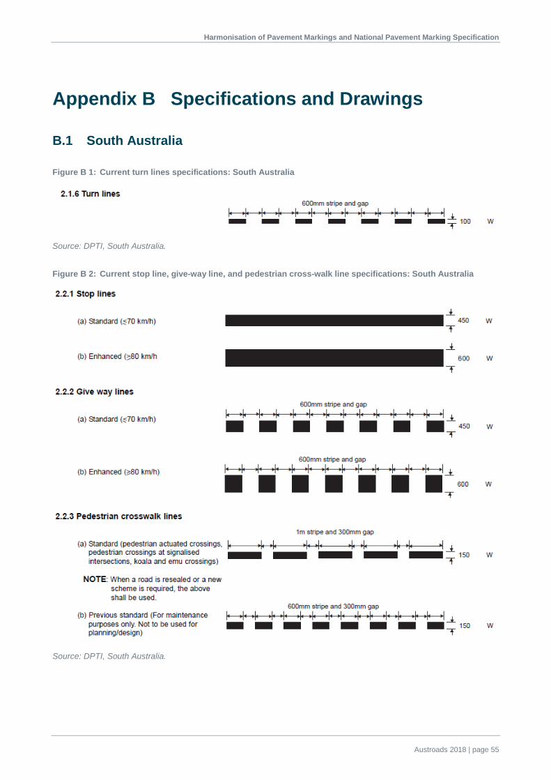
Harmonisation of Pavement Markings and National Pavement Marking Specification
Austroads 2018 | page 55
Appendix B Specifications and Drawings
B.1 South Australia
Figure B 1: Current turn lines specifications: South Australia
Source: DPTI, South Australia.
Figure B 2: Current stop line, give-way line, and pedestrian cross-walk line specifications: South Australia
Source: DPTI, South Australia.

Harmonisation of Pavement Markings and National Pavement Marking Specification
Austroads 2018 | page 56
Figure B 3: Continuations of pedestrian cross-walk specifications: South Australia
Source: DPTI, South Australia.
Figure B 4: Current pavement bar specifications: South Australia
Source: DPTI, South Australia.
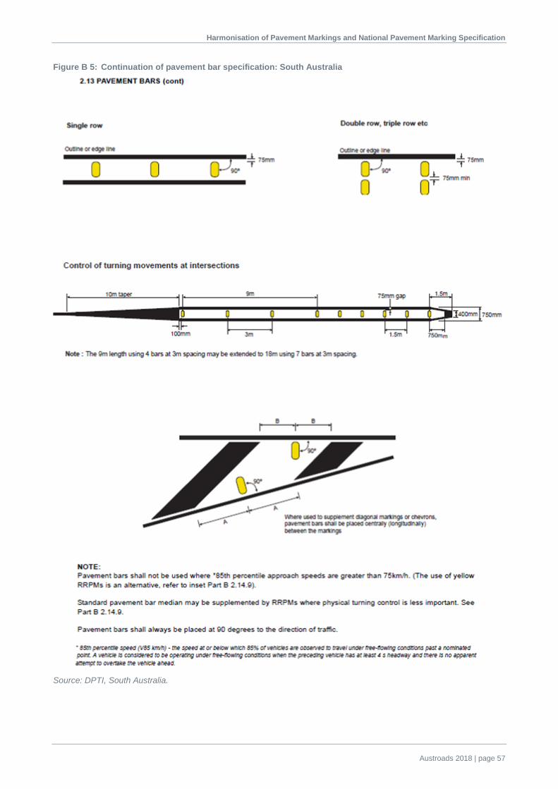
Harmonisation of Pavement Markings and National Pavement Marking Specification
Austroads 2018 | page 57
Figure B 5: Continuation of pavement bar specification: South Australia
Source: DPTI, South Australia.

Harmonisation of Pavement Markings and National Pavement Marking Specification
Austroads 2018 | page 58
Figure B 6: Use of intersection pavement arrows: South Australia
Notes:
1 Black symbols indicate arrows to be marked. 2 Grey symbols indicate manoeuvres which are permitted by regulations but which need not be marked. 3 On some intersection approaches, it may be necessary to combine two or more of the marking methods shown. 4 Arrows for all movements shall be marked on multi-lane side road approaches to signal controlled ‘T’ intersections
and on all multi-lane approaches to roundabouts.
Source: DPTI, South Australia.

Harmonisation of Pavement Markings and National Pavement Marking Specification
Austroads 2018 | page 59
Figure B 7: Arrows – common types: South Australia
Source: DPTI, South Australia.

Harmonisation of Pavement Markings and National Pavement Marking Specification
Austroads 2018 | page 60
Figure B 8: Arrows – special types: South Australia
Source: DPTI, South Australia.

Harmonisation of Pavement Markings and National Pavement Marking Specification
Austroads 2018 | page 61
Figure B 9: Arrows – lane change: South Australia
Source: DPTI, South Australia.
Figure B 10: Arrows – expressway exit: South Australia
Source: DPTI, South Australia

Harmonisation of Pavement Markings and National Pavement Marking Specification
Austroads 2018 | page 62
B.2 Queensland
Figure B 11: WCLT at channelised right-turn intersections: Queensland
Source: TMR (2017).

Harmonisation of Pavement Markings and National Pavement Marking Specification
Austroads 2018 | page 63
Figure B 12: WCLT at basic right-turn intersections and private property entrances: Queensland
Source: TMR (2017).
Figure B 13: WCLT to double barrier line transition at right-turn intersections: Queensland
Source: TMR (2017).

Harmonisation of Pavement Markings and National Pavement Marking Specification
Austroads 2018 | page 64
Figure B 14: WCLT transition at a narrow structure: Queensland
Source: TMR (2017).
Figure B 15: WCLT transition at successive narrow structures: Queensland
Source: TMR (2017).

Harmonisation of Pavement Markings and National Pavement Marking Specification
Austroads 2018 | page 65
Figure B 16: WCLT treatment at overtaking/climbing lanes: Queensland
Source: TMR (2017).
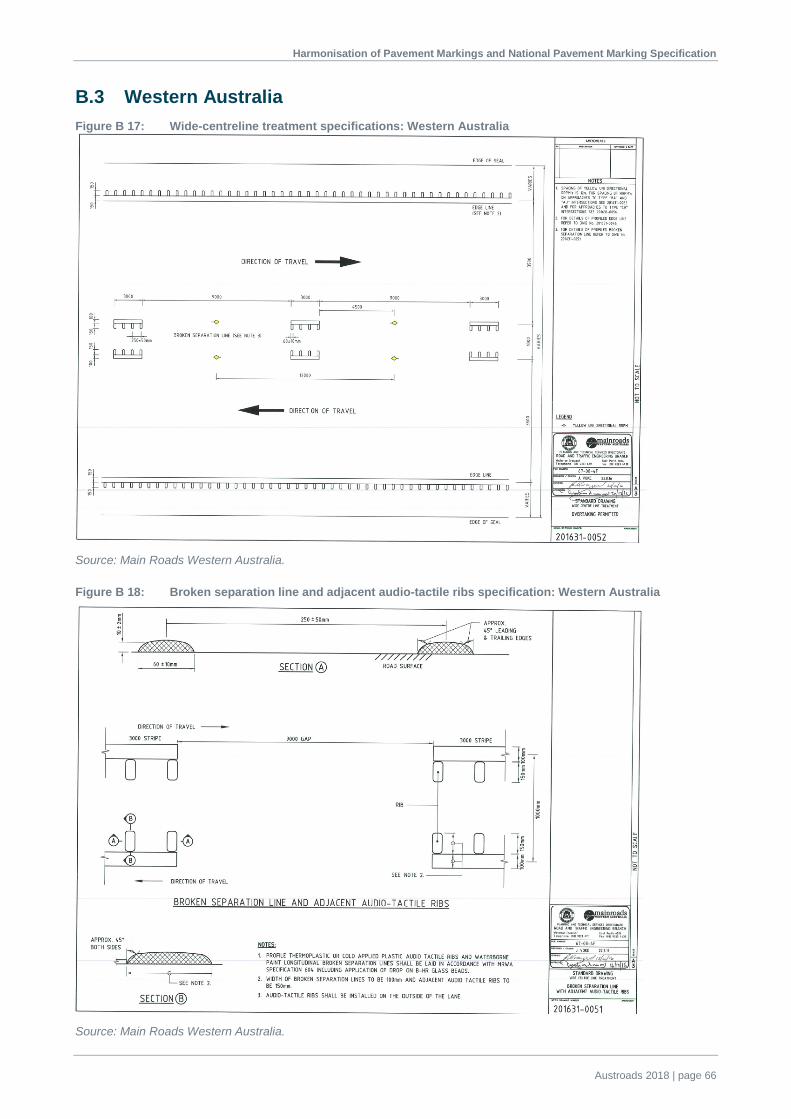
Harmonisation of Pavement Markings and National Pavement Marking Specification
Austroads 2018 | page 66
B.3 Western Australia Figure B 17: Wide-centreline treatment specifications: Western Australia
Source: Main Roads Western Australia.
Figure B 18: Broken separation line and adjacent audio-tactile ribs specification: Western Australia
Source: Main Roads Western Australia.

Harmonisation of Pavement Markings and National Pavement Marking Specification
Austroads 2018 | page 67
Figure B 19: Transition into wide-centreline treatment specification: Western Australia
Source: Main Roads Western Australia.
Figure B 20: Edge line adjacent audio-tactile rib specifications for Western Australia
Source: Main Roads Western Australia.

Harmonisation of Pavement Markings and National Pavement Marking Specification
Austroads 2018 | page 68
Figure B 21: Double two-way barrier line and adjacent audio-tactile ribs specification: Western Australia
Source: Main Roads Western Australia.
Figure B 22: Intersection treatment specifications: Western Australia
Source: Main Roads Western Australia.

Harmonisation of Pavement Markings and National Pavement Marking Specification
Austroads 2018 | page 69
Figure B 23: Intersection treatment specification: Western Australia
Source: Main Roads Western Australia.
Figure B 24: Wide-centreline treatment specification: Western Australia
Source: Main Roads Western Australia.

Harmonisation of Pavement Markings and National Pavement Marking Specification
Austroads 2018 | page 70
Figure B 25: Edge line adjacent audio-tactile rib specification: Western Australia
Source: Main Roads Western Australia.
Figure B 26: Double one-way barrier line and adjacent audio-tactile ribs specification: Western Australia
Source: Main Roads Western Australia.

Harmonisation of Pavement Markings and National Pavement Marking Specification
Austroads 2018 | page 71
Figure B 27: Wide-centreline treatment broken line separation specification: Western Australia
Source: Main Roads Western Australia.
Figure B 28: Audio-tactile ribs specification: Western Australia
Source: Main Roads Western Australia.

Harmonisation of Pavement Markings and National Pavement Marking Specification
Austroads 2018 | page 72
Figure B 29: Edge line and adjacent audio-tactile ribs specification: Western Australia
Source: Main Roads Western Australia.
Figure B 30: Audio-tactile longitudinal edge line specification: Western Australia
Source: Main Roads Western Australia.

Harmonisation of Pavement Markings and National Pavement Marking Specification
Austroads 2018 | page 73
Figure B 31: Freeway exit pavement arrows specifications: Western Australia
Source: Main Roads Western Australia.
Figure B 32: Pavement arrows specifications: Western Australia
Source: Main Roads Western Australia.

Harmonisation of Pavement Markings and National Pavement Marking Specification
Austroads 2018 | page 74
B.3.1 Audio-tactile Trial (York-Merrdein Road)
Notes of site inspection undertaken by Ron Koorengevel (MRWA) and Adrian Bonner (MRWA) on 15 May 2017.
Trial Site No. 4 – SLK 55.04 to 56.71 (Figure B 33 and Figure B 34)
This treatment consists of the following:
• Double two-way/double one-way barrier lines
– 80 mm wide line/80 mm wide gap/80 mm wide line
– 100 mm wide grey ribs between lines.
• Broken separation line
– 80 mm wide line with 3 m stripe and 9 m gap.
– 100 mm wide grey ribs adjacent to the line continuously.
• Edge line
– 120 mm wide
– 150 mm wide white ribs on line.
• Comments
– Grey ribs give the appearance of a ‘removed line’ at night.
– Grey ribs give good audio tactile response.
– Grey ribs do not provide additional forward delineation or wet weather benefits unlike the edge line.
– Linemarking is consistent with what is on the network.
Figure B 33: Start of Trial Site No. 4
Source: Main Roads Western Australia.

Harmonisation of Pavement Markings and National Pavement Marking Specification
Austroads 2018 | page 75
Figure B 34: Edge line and centreline at start of Trial Site No. 4
Source: Main Roads, Western Australia.
Trial Site No. 5 (Figure B 35 and Figure B 36)
This treatment consists of the following:
• Double two-way/double one-way barrier lines
– 100 mm wide line/100 mm wide gap/100 mm wide line
– 100 mm wide grey ribs between lines.
• Broken separation line
– 100 mm wide line with 3 m stripe and 9 m gap
– 100 mm wide grey ribs adjacent to the line continuously.
• Edge line
– 120 mm wide
– 150 mm wide white ribs on line.
• Comments
– Preferred treatment.
– Grey ribs give the appearance of a ‘removed line’ at night.
– Grey ribs give good audio tactile response.
– Grey ribs do not provide additional forward delineation or wet weather benefits unlike the edge line.
– Linemarking is consistent with what is on the network.
• Wider lines are preferred option and ledge lines will go to 150 mm wide.
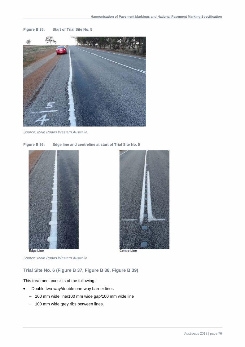
Harmonisation of Pavement Markings and National Pavement Marking Specification
Austroads 2018 | page 76
Figure B 35: Start of Trial Site No. 5
Source: Main Roads Western Australia.
Figure B 36: Edge line and centreline at start of Trial Site No. 5
Source: Main Roads Western Australia.
Trial Site No. 6 (Figure B 37, Figure B 38, Figure B 39)
This treatment consists of the following:
• Double two-way/double one-way barrier lines
– 100 mm wide line/100 mm wide gap/100 mm wide line
– 100 mm wide grey ribs between lines.

Harmonisation of Pavement Markings and National Pavement Marking Specification
Austroads 2018 | page 77
• Broken separation line
– 2 x 100 mm wide line with 3 m stripe and 9 m gap
– 100 mm wide grey ribs between lines.
• Edge Line
– 120 mm wide edge line
– 150 mm wide white ribs on line.
• Comments
– Installation of 2 x 100 mm wide broken separation lines may cause confusion to drivers.
– Grey ribs give the appearance of a ‘removed line’ at night.
– Grey ribs give good audio tactile response.
– Grey ribs do not provide additional forward delineation or wet weather benefits unlike the edge line.
– Linemarking is consistent with what is on the network.
Figure B 37: Start of Trial Site No. 6 – edge of road
Source: Main Roads Western Australia.
Figure B 38: Start of Trial Site No. 6 – centre of road
Source: Main Roads Western Australia.
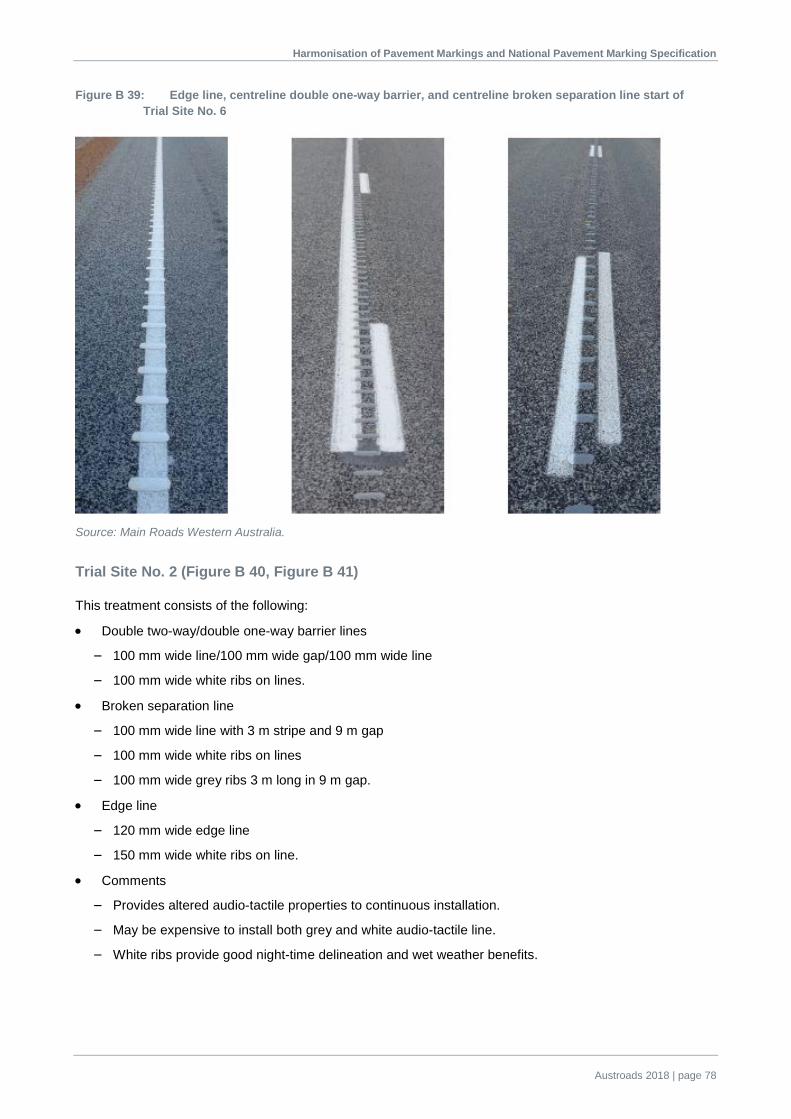
Harmonisation of Pavement Markings and National Pavement Marking Specification
Austroads 2018 | page 78
Figure B 39: Edge line, centreline double one-way barrier, and centreline broken separation line start of Trial Site No. 6
Source: Main Roads Western Australia.
Trial Site No. 2 (Figure B 40, Figure B 41)
This treatment consists of the following:
• Double two-way/double one-way barrier lines
– 100 mm wide line/100 mm wide gap/100 mm wide line
– 100 mm wide white ribs on lines.
• Broken separation line
– 100 mm wide line with 3 m stripe and 9 m gap
– 100 mm wide white ribs on lines
– 100 mm wide grey ribs 3 m long in 9 m gap.
• Edge line
– 120 mm wide edge line
– 150 mm wide white ribs on line.
• Comments
– Provides altered audio-tactile properties to continuous installation.
– May be expensive to install both grey and white audio-tactile line.
– White ribs provide good night-time delineation and wet weather benefits.

Harmonisation of Pavement Markings and National Pavement Marking Specification
Austroads 2018 | page 79
Figure B 40: Start of Trial Site No. 2
Source: Main Roads Western Australia.
Figure B 41: Edge line, centreline double two-way barrier, and centreline double one-way barrier at start of Trial Site No. 2
Source: Main Roads Western Australia.
Trial Site No. 1 (Figure B 42, Figure B 43, Figure B 44)
This treatment consists of the following:
• Double two-way/double one-way barrier lines
– 100 mm wide line/100 mm wide gap/100 mm wide line
– 100 mm wide white ribs on lines.
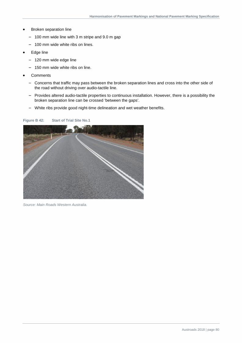
Harmonisation of Pavement Markings and National Pavement Marking Specification
Austroads 2018 | page 80
• Broken separation line
– 100 mm wide line with 3 m stripe and 9.0 m gap
– 100 mm wide white ribs on lines.
• Edge line
– 120 mm wide edge line
– 150 mm wide white ribs on line.
• Comments
– Concerns that traffic may pass between the broken separation lines and cross into the other side of the road without driving over audio-tactile line.
– Provides altered audio-tactile properties to continuous installation. However, there is a possibility the broken separation line can be crossed ‘between the gaps’.
– White ribs provide good night-time delineation and wet weather benefits.
Figure B 42: Start of Trial Site No.1
Source: Main Roads Western Australia.

Harmonisation of Pavement Markings and National Pavement Marking Specification
Austroads 2018 | page 81
Figure B 43: Edge line, centreline double two-way barrier, centreline double one-way barrier, and centreline broken separation line at start of Trail Site No.1
Source: Main Roads Western Australia.

Harmonisation of Pavement Markings and National Pavement Marking Specification
Austroads 2018 | page 82
Figure B 44: Centreline arrangements
Source: Main Roads Western Australia.
B.4 Victoria
The patterns and dimensions of longitudinal lines used in Victoria are shown in Figure B 45. Alternative line patterns in high-speed areas (80 km/h or greater) are subject to approval by VicRoads.
Figure B 45: Summary of longitudinal lines used in Victoria
Source: VicRoads Supplement to AS 1742.2:2009 – Edition 1 (2015).
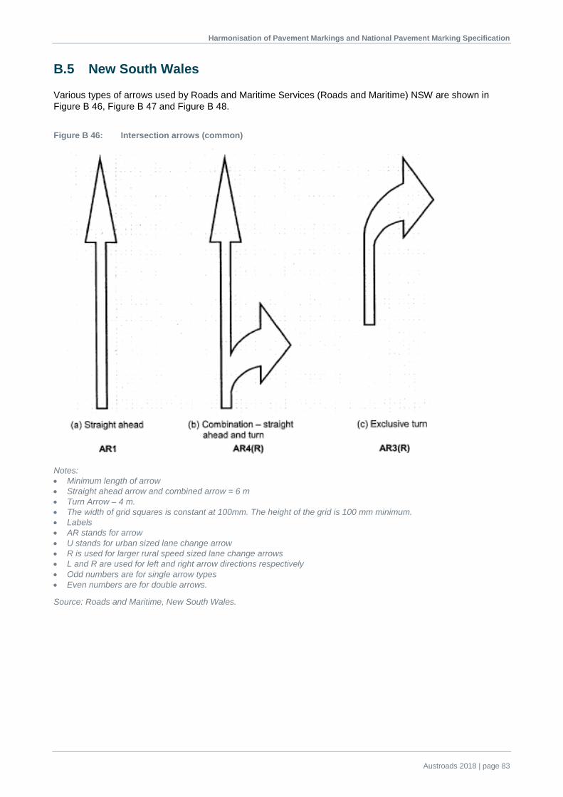
Harmonisation of Pavement Markings and National Pavement Marking Specification
Austroads 2018 | page 83
B.5 New South Wales
Various types of arrows used by Roads and Maritime Services (Roads and Maritime) NSW are shown in Figure B 46, Figure B 47 and Figure B 48.
Figure B 46: Intersection arrows (common)
Notes: • Minimum length of arrow • Straight ahead arrow and combined arrow = 6 m • Turn Arrow – 4 m. • The width of grid squares is constant at 100mm. The height of the grid is 100 mm minimum. • Labels • AR stands for arrow • U stands for urban sized lane change arrow • R is used for larger rural speed sized lane change arrows • L and R are used for left and right arrow directions respectively • Odd numbers are for single arrow types • Even numbers are for double arrows.
Source: Roads and Maritime, New South Wales.

Harmonisation of Pavement Markings and National Pavement Marking Specification
Austroads 2018 | page 84
Figure B 47: Intersection arrows (special)
Notes: • Minimum length arrow • Double turn arrow = 4 m • U-turn arrow = 5 m • Sequential turns and 45° turn arrows = 6 m. • The width of grid squares is constant at 100 mm. The height of grid squares is 100 mm minimum. • Labels • AR stands for arrow • U stands for urban sized lane change arrow • R is used for larger rural speed sized lane change arrows • L and R are used for left and right arrow directions respectively • Odd numbers are for single arrow types • Even numbers are for double arrows.
Source: Roads and Maritime, New South Wales

Harmonisation of Pavement Markings and National Pavement Marking Specification
Austroads 2018 | page 85
Figure B 48: Lane change arrows
Notes: When installing arrows, it is recommended that the head be laid first.
Source: Roads and Maritime, New South Wales.
B.5.1 Audio-tactile Linemarkings
Types of audio-tactile linemarking used by Roads and Maritime NSW are shown in Figure B 49, Figure B 50 and Figure B 51.
Figure B 49: Type A profile linemarking
Source: Roads and Maritime, New South Wales.

Harmonisation of Pavement Markings and National Pavement Marking Specification
Austroads 2018 | page 86
Figure B 50: Type B profile linemarking
Source: Roads and Maritime, New South Wales.
Figure B 51: Profile line on motorways and duel carriageways
Notes: • The ribs shall be 60 mm ± 10 mm (measured along the line with a rub spacing of 250 mm ± 50 mm. • The height of ribs shall be 10 mm ± 2 mm.
Source: Roads and Maritime, New South Wales.

Harmonisation of Pavement Markings and National Pavement Marking Specification
Austroads 2018 | page 87
Appendix C International Review of Audio-tactile Linemarkings
C.1 Introduction
C.1.1 Purpose
The purpose of Austroads Project AAM2101 is to achieve national harmonisation of pavement markings and to develop a national performance specification/criteria for pavement markings.
The project involved an investigation of longitudinal and transverse line types and widths and other pavement markings used by different road agencies (states, territories and New Zealand) with the aim of harmonising them as much as practical. The project also investigated road agency pavement marking specifications, from which a draft national performance specification/criteria for pavement markings was developed.
C.1.2 Background
The review presented in this Appendix provides relevant background information to the documentation of each agency’s practice in the following countries:
• New Zealand
• United States of America (USA)
• Canada
• Conference of European Directors of Roads (CEDR)
• Norway
• Germany
• Austria
• The Netherlands
• Hong Kong
• Sweden
• Belgium.
This literature review provides input into other milestones within the overall project. It is intended that these results support the development of each states audio-tactile linemarking and maintenance processes.
C.1.3 Terminology
It is acknowledged that a range of terms are in use for audio-tactile linemarkings (ATLM) and that they differ between countries. The terms in use in different countries are:
• audio-tactile linemarkings – Australia, Belgium
• audio-tactile profiled (ATP) road markings – New Zealand
• rumble strips (milled or raised) – USA, Canada, Norway, CEDR, Germany, Austria
• raised pavement markers – USA

Harmonisation of Pavement Markings and National Pavement Marking Specification
Austroads 2018 | page 88
• profiled road markings/enhanced road markings – Norway
• profiled linemarkings – Sweden
• structured road markings – Belgium.
C.2 New Zealand
C.2.1 Maintenance of Audio-tactile Profiled Road Markings
In New Zealand, ATP road markings are generally used longitudinally as edge lines or centrelines (Lester, Dravitzki & Burton 2017). They stipulated that the maintenance of ATP road marking should include the monitoring of visual effects during daylight and night conditions, including wet conditions where practicable. Objective measures of the visual properties of ATP road markings are desirable, but if unavailable then subjective monitoring of visual performance can be an effective alternative and is preferable to no visibility monitoring.
Techniques for refreshing ATP road marking visibility may be cleaning of the existing marking or recoating the marking with an application of paint (or other road marking material) (Lester et al. 2017).
Audio-tactile profiled (ATP) blocks (ribs) can be lost or removed over time for a number of reasons including road damage, residents’ noise complaints or surface resealing projects. The NZTA Specification P30 (NZTA 2009) states that the maximum permitted block loss is 5% within each kilometre, with no more than 10 missing blocks in sequence, except in exceptional circumstances (NZTA 2010).
The NZTA specification M24 (Transit New Zealand 2006) outlines the maintenance requirements for ATP road markings. The maintenance period for ATP road markings is a minimum of 12 months for installation of ATP road marking contracts:
• of duration of three months or less – the maintenance period commences once all ATP road markings are installed to the lead engineer’s satisfaction
• longer than three months duration – the contractor can apply at three-monthly intervals to have the maintenance period commence at any section of the ATP road markings where they have been installed to the satisfaction of the lead engineer.
Specification M24 also states that within the maintenance period, the contractor will be held responsible for ATP road marking defects, including, but are not limited to, installed road markings that exhibit signs of:
• spalling, flaking, or any other form of deterioration (other than fair wear and tear) resulting in the ATP road marking not complying with the specified dimensional requirements
• loss of surface beads or aggregate
• loss of blocks or flattening of blocks.
Specification P30 states that the contractor will not be held responsible for road marking defects where it can be shown that the defect can be directly attributed to:
• on-road-operations such as gritting or snow-ploughing
• road/pavement-behaviour such as bleeding, cracking or rutting
• pavement surface or substrate failure such that ATP markings are punched into the pavement surface
• tampering by a third party or unreasonable and unexpected traffic
• abnormal conditions.

Harmonisation of Pavement Markings and National Pavement Marking Specification
Austroads 2018 | page 89
It is important that the respective responsibilities of contractors who install and maintain ATP road markings, outlined in P30 and M24, are well understood and clearly defined in contractual agreements. The correct installation and active monitoring by network managers ensures that maintenance of ATP road markings is adequate (NZTA 2010).
Suggested management for ATP road markings includes best practice monitoring of regular measurement of visual effects, possibly using a mobile retro-reflectometer, and regular measurement of audible effects, possibly with a sound level meter mounted in the vehicle. However, as audible effects cannot measure the tactile event itself, alternative practices will need to be implemented to measure this. Alternatively, the research project has discussed a subjective rating system and this could be developed as a complement to objective measurements or as an interim measure until there is a fully developed method for objective measurements.
C.2.2 Cleaning ATP Road Markings
Contractors and network managers have shown that cleaning of ATP road markings using low-pressure water blasting can significantly renew the retro-reflectivity of the markings. In a recent investigation of ATP performance in the upper North Island of New Zealand, it was found that when ATP road markings are still within specification but visibly dirty, their retroreflectivity is reduced (Mackie 2009). Therefore, it is recommended that the maintenance contractors wash the ATP road markings at least once, preferably mid-way through the expected life of the ATP road markings. This relatively inexpensive procedure can significantly increase the effective life of the ATP road markings. Provision for cleaning should be built into maintenance contracts (NZTA 2010). However, the guidelines do not mention what occurs if there is a storm event that produces a large amount of mud. In this case the ATP Road Markings may need to be cleaned outside of the schedule.
C.2.3 Removal, Reinstatement and Reseals
The removal of ATP ribs should be avoided where possible, but is sometimes necessary, e.g. when nearby residents have issues with the noise they generate. Recent trials in New Zealand suggest that a grader blade (if the ribs are big enough) or grinding are effective options for removing these blocks. High-pressure water blasting appears to be most effective but is also very costly and can be seen to be wasteful. There are some examples where ATP road markings were covered by a reseal. In cases where the ATP ribs were relatively new, a clear audio-tactile response was still provided. In cases when the ribs were old and worn down there was little or no residual ATP effect (NZTA 2010).
Given the information that exists, the following is recommended for ATP removal or reseals (NZTA 2010):
• For reseals, if the ATP ribs are significantly worn or have been punched into the seal, then resealing and reinstating the ATP road marking should proceed as usual with no ATP removal or pre-treatment.
• If resealing is to occur over relatively new ribs (and this should be avoided as much as possible by careful network management) and a fine-grade chip is to be used for the reseal, then the ATP should be resealed over and a continuous line should be marked either immediately next to or over the existing ribs. The ATP road marking will need to be reinstated when the ribs fall below specification.
• If a coarse-grade chip is to be used over fresh ATP ribs and residual ATP response is non-existent or very faint, then reinstatement of ATP road marking can proceed as usual; otherwise the ribs must be mechanically removed prior to the reseal.
The audio effects of examples of ATP road markings with in-lane reseal or seal over were measured by Lester et al. (2017). In-lane reseal is where the road surface of the trafficked lane adjacent to the ATP road markings is resealed but the non-trafficked shoulder and the ATP road marking itself is left without being resealed. ‘Seal over’ refers to when the ATP road marking is sealed-over during resealing with the intention of its audio-tactile effects to be retained through the reseal layer. With ‘good practice’, the audio-tactile effects of the ATP road marking are unaffected by the in-lane reseal.
Harmonisation of Pavement Markings and National Pavement Marking Specification
Austroads 2018 | page 90
With resealing over ATP road markings, some of the pre-reseal audio/tactile effects can be successfully retained. However, the success is variable and may be difficult to predict, depending on both the pre-reseal condition of the raised ribs and the size of chips used during the resealing. Of the two practices, in-lane reseal appears more practicable because there is more certainty that the residual audio/tactile life will be unimpaired. If road surface reseal is intended where ATP road markings are still working effectively, it is recommended that in-lane reseal be considered as the preferred method (Lester et al. 2017).
C.2.4 Renewal and Replacement
Many factors determine the service life of an ATP road marking installation. These include: the type of ATP product and how it is installed; the age, material and condition of the road surface before the ATP installation; traffic composition and volume; and the placement of the ATP lines in relation to the road geometry, which may determine the frequency of vehicle encroachment (Edgar, Mackie & Baas 2009).
Recent research has shown that the estimated lifetime is six to eight or more years. Theoretically, the effective life of ATP road markings is comparable to the effective life of the road surface on which they are laid. However, to date, many ATP road markings have been introduced onto road surfaces that are already midway through their lives. In addition, road surfaces do sometimes fail prematurely. In these situations, ATP road markings have effective life remaining at a time when the road’s surface effective life is expired and a reseal of the road surface is scheduled (Lester et al. 2017).
Research in the upper North Island has shown that ATP road markings typically have a life of approximately three to four years (Mackie 2009), depending on the road environment. Factors which affect the life include traffic volume and weather patterns. A road seal’s life is typically eight years, which means that ATP road markings generally need to be renewed within the life of the road seal. Under-performance of ATP road markings may result from reduced retroreflectivity or from reduced audio-tactile response. Under-performance typically occurs when the rib height of the ATP road markings has worn down to 3–4 mm. In recent trials by OPUS Central Laboratories, it was concluded that simulated ATP ribs were not reliably detectable below a height of approximately 3 mm (NZTA 2010).
Where ATP road markings have reached their effective end-of-life and a reseal is not due for some time, the road markings need to be reinstated or replaced. If there are still clearly detectable ribs, then they will need to be ground down or graded to the surrounding road surface. An alternative approach is to leave undamaged existing ribs in place, and to provide new ribs with spacing that matches the existing ribs. For both solutions, careful monitoring would need to be undertaken in order to ensure sufficient adhesion and alignment of the new markings over the old ones (NZTA 2010).
C.2.5 Product Materials Used for ATP Road Markings
New Zealand has adopted the raised rib form of audio-tactile profiled (ATP) road markings. The ribs are generally formed using a thermoplastic or two-part reactive cod-hardening material (referred to in the sector as ‘cold applied’) (Lester et al. 2017). The specific product that will be used to form the road marking must always be approved by the NZTA before installation.
The requirements for technical installation, such as the road surface texture, or the cost generally determine which of the two products used (Edgar et al. 2009).
There are advantages and disadvantages to both thermoplastics and cold applied plastics. In a study undertaken in upper North Island (Mackie 2009) it was found that cold applied plastic ribs were more resistant to wear than thermoplastic ribs, but cold applied plastics were, in some situations, more likely to be punched into the seal. On the other hand, thermoplastic ribs have better retroreflectivity properties over their lifetime. However, these results are still speculative and the comparisons have lacked statistical power (NZTA 2010).
More recent studies suggest that there may be larger differences in performance level between proprietary brands of thermoplastics and cold applied plastics then there are between the two categories of material. Due to this, the NZTA suggest that, when developing ATP road markings, both categories should be considered and the one of higher quality at the time should be chosen. Consideration also needs to be taken of the whole-of-life costings including the costs of maintenance reseals and renewal (NZTA 2010).

Harmonisation of Pavement Markings and National Pavement Marking Specification
Austroads 2018 | page 91
C.3 United States of America
C.3.1 Milled Rumble Strips
Milled rumble strips are the most prevalent form of rumble strip used in the USA. This treatment is milled into the roadway surface by using a rotary milling machine. It functions by allowing the tyre of a vehicle to drop down into the milled space generating both a sound and a vibration to alert the driver.
C.3.2 General Maintenance
Milled rumble strips typically require little to no maintenance. This is because they are essentially self-cleaning. Snow, ice, rain, sand or mud that can accumulate within the milled rumble strip generally does not remain due to the vibration and wind generated by passing vehicles (Federal Highway Administration (FHWA) 2015). The Missouri, South Carolina, Pennsylvania and Washington Departments of Transportation (DOT) all reported no use of preventative maintenance treatments on their rumble strips. This is because weather appears to play no significant role in the durability of milled rumble strips (FHWA 2016a, 2016b).
C.3.3 Maintenance of Rumble Strips During Pavement Maintenance
Different agencies have different approaches to the maintenance of rumble strips during pavement maintenance. Some agencies re-install the rumble strips immediately, as part of the resurfacing project, while others choose to re-install them during area-wide rumble strip installation projects, which are scheduled at intervals (such as annually) to replace rumble strips on all recently paved projects (FHWA 2015).
Surface preparation when paving over existing rumble strips also varies across agencies (FWHA 2015):
• some agencies have found that overlaying the rumble strip works adequately
• other agencies use a method of milling out the rumble strips and either inlaying or overlaying the new pavement works more effectively.
Many agencies use the second method of milling the pavement before placing the new asphalt overlay. This option is preferable because it removes the existing rumble strip, negating the need to treat existing rumble strips when new asphalt is overlayed.
C.3.4 National Cooperative Highway Research Program Maintenance Survey Results
The following are the results on a survey of maintenance methods from the National Cooperative Highway Research Program (NCHRP) Synthesis 490. The questions were focused on the maintenance practices of rumble strips and stripes that are used by DOTs. Forty-one DOTs were surveyed. The questions that were asked were listed by category: sealant, life expectancy, winter maintenance, and maintaining the pavement marking within the rumble strip (Hawkins & Smadi 2016).
• Sealant – the agencies were asked whether they re-apply sealant over existing rumble strips over-time. Five of the 41 agencies re-apply sealant, based on a pavement condition assessment with no standard frequency or schedule for re-application.
• Life expectancy – the agencies were asked if they have a life expectancy for their rumble strips or whether the replacement of the rumble strips is based on pavement re-surfacing and rehabilitation. Rumble strip life expectancy is based on the tactile and audible effectiveness of the rumble strip throughout time. Thirty of the 41 agencies (73%) replace their rumble strips based on pavement re-surfacing projects as opposed to base on the life-expectancy of the rumble strip.

Harmonisation of Pavement Markings and National Pavement Marking Specification
Austroads 2018 | page 92
• Winter maintenance – the agencies were asked if maintenance operations that occur during the winter months varied based on the presence of rumble strips in the road. Winter maintenance methods referred to snow removal, sanding, salt and brine applications. Of the 41 agencies, 95% do not alter their winter maintenance practices based on the presence of rumble strips.
• Maintaining the pavement marking within the rumble strip area – the agencies were asked how they maintain pavement marking within rumble strips. The survey showed that 85% of agencies paint over the existing marking, while the other agencies remove the existing pavement markings prior to reapplication. Only 20% noticed differences in retroreflectivity with reapplication.
C.3.5 Mitigating Adverse Effects
There were early concerns that the installation of milled rumble strips would accelerate pavement deterioration, but these were proven to be unfounded. However, it is now common practice to locate milled rumble strips at least a few inches from any joints in the road surface. This helps to reduce any accelerated pavement deterioration that might occur. Rumble strips that are placed in a pavement that is in good condition are most effective because they will be in place longer. Recent experience in Michigan has shown that shoulder preventative maintenance treatments such as chip seal, ultra-thin asphalt, and micro-surface, can be compatible with rumble strips. A chip seal placed on top of existing rumble strips has been shown to retain the basic shape of the rumble strip, although some cross-section is lost. Micro-surface and ultra-thin asphalt overlays fill in existing lines of rumble strips; however, a new line of rumble strip can be cut into the overlay at the same location without significant delaminating caused by the underlying filled-in rumbles (FHWA 2011a, 2011b).
C.3.6 Raised Rumble Strips
Although research has suggested that milled rumble strips are the most effective type of rumble strips, raised rumble strips have been applied in states with warmer climates. Raised rumble strips consist of raised pavement markers that sit side by side to create an edge line or centreline. These raised pavement markers generally consist of a plastic insert within a thermoplastic road marking or are made from very tick epoxy tape (FHWA 2016a, 2016b).
Additionally, it has been noted that rumble strips contribute to a 36% reduction of fatalities along the edge line, and 44% reduction of fatalities along the centreline (FHWA 2016a, 2016b). Additionally, noise is a focus for further research in relation to rumble strips.
C.3.7 Issues Arising from Snow-Ploughing
Raised rumble strips in the USA can have a height anywhere in the range of 6 mm to 13 mm. The use of raised rumble strips is usually restricted to warmer climates that do not require snow removal, as the raised blocks can interfere with snow ploughing (FHWA 2011a, 2011b). Snow-plough blades passing over raised rumble strips tend to scrape them off the road surface (FHWA 2016a, 2016b).
C.3.8 Raised Pavement Markers (RPM)
The Roadway Delineation Practices Handbook (the Handbook) developed by the Federal Highway Administration (FHWA 1994) offers guidelines on how to implement the standards in the Manual for Uniform Traffic Control Devices (MUTCD). The Handbook summarises some commonly-used maintenance strategies that state DOTs use to examine RPMs routinely. It was noted in the Handbook that some of the authors found that there was not much data available about snow-ploughable raised pavement markers (SRPMs), although the maintenance methods for non-snow-ploughable RPMs provides some insight into how both types are maintained by the DOTs.

Harmonisation of Pavement Markings and National Pavement Marking Specification
Austroads 2018 | page 93
C.3.9 Use of Thermoplastics
Thermoplastic polymers are used for raised pavement markers because these materials provide more durability and maintain their reflectivity through most of their lifetime. Thermoplastics are generally more durable towards the everyday effects placed upon road markings such as: wear, exposure to weather, and road chemicals. Thermoplastic polymers also have a short ‘track-free time’ than other materials that are used. ‘Track-free time’ refers to the amount of time between the installation of the thermoplastic polymer on the pavement surface and the time when it will no longer transfer to the tyres of vehicles that are driving over it. A shorter ‘track-free time’ increases the efficiency of the road markings because it reduces the amount of time that the traffic is disrupted (US Patent & Trademark Office (USPTO) 2016).
C.3.10 Thermoplastics Cracking in Cold Climates
As pavement road markings are outdoors and exposed to weather conditions all-year round they can deteriorate. It has been seen that, at low temperatures, thermoplastics can become quite brittle and can crack. In a current study by 3M innovative properties company (USPTO 2016), it was recognised that by including core-shell particles in thermoplastic road markings, including ethylene vinyl acetate and/or ethylene acrylic acid, the cold weather crack-resistance of the road markings can be improved. The study outlined some percentages and composites that can be used in order to increase the durability of the thermoplastics in cold weather, whilst achieving an optimum weight and not comprising other properties such as retroreflectivity. For more information on this study and the different chemical compositions used, refer to the article in the reference list.
C.3.11 Use of Snow-ploughable Raised Pavement Markers (SRMP)
The following list is the result of an electronic survey on SRPMs conducted in 2005 by the Missouri Department of Transportation through the American Association of State Highway and Transportation Officials’ Research Advisory Committee (AASHTO RAC) membership. Twenty US states and two Canadian provinces responded to the survey. These results were as follows:
• Twelve agencies reported using SRPMs, with three indicating that their use was currently experimental.
• Five of the nine agencies whose use of SRPMs was non-experimental responded that they were aware of a single or occasional occurrence where an SRPM had come loose from the pavement. Determined causes of this failure included: hits from snowplough blades, pavement failures, and improper installation were the reasons cited most often.
• The DOTs of Alaska, Montana and Colorado stated they do not use SRPMs because of heavy snowplough operations.
• New York DOT stated they were using SRPMs less often, with wet-night reflective tape used as an alternative (Fontaine & Gillespie 2009).
C.3.12 Expected Lifetime Method of Maintenance
In most cases, the states used an expected lifetime to schedule the replacement of RPMs on their highways. The Handbook did note that this method may not always be cost effective because some RPMs may continue to be well-functioning and proving good visibility after the expected lifetime, but would be removed in an overall overhaul (Fontaine & Gillespie 2009).
Bahar et al. (2004) summarised the most recent methods of RPM maintenance based on expected lifetime. In Indiana, SRPMs are replaced on a cycle, with the cycle determined according to the number of lanes on the road and the average daily traffic (Table C 1).

Harmonisation of Pavement Markings and National Pavement Marking Specification
Austroads 2018 | page 94
Table C 1: SRPM lens replacement cycle for snow-ploughable raised pavement markers in Indiana
No. of lanes Average daily traffic Replacement cycle (yr.)
2 < 5 000 4
5 000 to 15 000 3
> 15 000 2
4 or more < 10 000 4
10 000 to 30 000 3
30 000 to 75 000 2
> 75 000 (inspected annually) 2
Source: Bahar et al. (2004).
C.3.13 Inspection Method of Maintenance
An alternate method to using an expected lifetime is used by some states (Table C 2). Regular inspections are conducted in order to determine which RPMs are at the end of their life. Those that need to be replaced will then have their castings and lenses replaced (Fontaine & Gillespie 2009). In most cases, inspection of RPMs to determine if they need replacing is conducted at night, either annually or towards the end of the expected lifetime of the RPM. During this inspection visibility is subjectively rated and the number of RPMs that are missing is noted (Fontaine & Gillespie 2009).
Table C 2: Criteria used by different agencies for replacing RPMs: inspection-based maintenance approach
State Criteria used
California RPMs are replaced when two successive retroreflective RPMs are missing
Florida RPMs are replaced when eight or more successive RPMs are missing
Massachusetts SRPMs are replaced if 30% or more are missing in an inspected section
Pennsylvania RPMs are visually inspected when work crews are performing other work in the area. They are then replaced as needed. Another study performed by the University of Iowa in 1998 expanded this list of maintenance practices by including several other states
Texas RPMs are replaced when 50% or more are missing in 1 mile of highway
New Jersey Through a visual inspection process, lenses are replaced only if the casting is intact
Source: Fontaine and Gillespie (2009).
An issue to be aware of when using a maintenance method of non-snow-ploughable RPMs to maintain SRPMs is that non-snow-ploughable RPMs do not have a metal casting. This means that the potential debris created form their dislodgement is not as severe as the debris created from the dislodgement of an SRPM.
C.4 Canada
C.4.1 Shoulder Rumble Strip Maintenance Guidelines
Studies have shown that, once milled rumble strips are installed, they require very little maintenance. As in the USA, the installation of shoulder rumble strips in a new or well-maintained pavement does not alter the rate of deterioration of the pavement.
The following guidelines are recommended to ensure the proper maintenance of shoulder rumble strips (Bahar, Longtin-Nobel & Wales 2001):
• When grading the gravel shoulders adjacent to partially-paved shoulders, care should be taken to prevent debris from entering the shoulder rumble strips.

Harmonisation of Pavement Markings and National Pavement Marking Specification
Austroads 2018 | page 95
• After milling, the shoulder rumble strip must be swept and the debris disposed of in an appropriate manner.
• During winter, snow ploughing and de-icing procedures should be undertaken as part of the normal road maintenance procedures. In the case that ice or snow accumulates in the grooves of the rumble strip, additional applications of de-icing procedures should be applied.
• During summer, inspection for cracking, potholing, water ponding and snow plough blade damage should be undertaken. If required, corrective measures should be taken in order to rectify damage. Corrective measures include crack sealing, pot hole patching, measures to ensure positive drainage, rehabilitation of pavement grinding, paving and re-grooving.
C.4.2 Centreline Rumble Strip Guidelines
In Alberta, Canada, centreline markings are repainted by the highway agencies after the installation of centreline rumble strips. Re-painting is undertaken in order to improve the visibility of the centreline, rather than just relying on the visibility of the milling. Re-painting is undertaken in both directions in order to ensure that the rumble strips are entirely coated with the paint and no areas have been missed. Presently, maintenance of milled rumble strips is conducted under regular highway maintenance practices, similar to shoulder rumble strips. There have not yet been any maintenance issues specific to rumble strips identified.
C.5 Norway
C.5.1 Auditory and Vibratory Devices to Prevent Involuntary Lane Departure
Norway has used profiled road markings both on centre and edge line since 1990. A research report from 1999 (The Foundation for Scientific and Industrial Research (SINTEF) report A99553, cited in Giaever 2011) showed that there was a 14% reduction (not significant) of head-on and run-off crashes after the installation of profiled road markings.
Due to the damage and wear caused to the road markings over time, Norway has increasingly used rumble strips as a supplement to the profiled road markings. Rumble strips are used both along the centre and edge line. Rumble strips are mainly used in the middle of the road to reduce head-on crashes. This treatment also decreases vehicle speed and increases the separation between opposing vehicles (Giaever 2011).
Both ordinary rumble strips and profiled rumble strips are not suitable in built-up areas because they cause noise. This problem can be minimised by the use of rumble strips with sinusoidal profiles, as they produce less noise to their surroundings while providing a sufficient alert to a driver crossing the strips (Giaever 2011).
C.5.2 Enhanced Road Markings
Enhanced road markings are a combination of ordinary road markings and milling in the road surface within the road markings. This type of road marking can be used both for centreline and edge line road markings. Enhanced road markings are used in order to give the road-user a ‘rumbling’ feedback when their vehicle crosses over the centreline or edge line. In the centreline application, this has the benefit of increasing the separation between vehicles travelling in opposite directions. Enhanced road markings also provide increased visibility of the line in adverse weather conditions, and in some cases, can help to prolong the life of the road marking (Engen, Giaever & Haukland 2011).

Harmonisation of Pavement Markings and National Pavement Marking Specification
Austroads 2018 | page 96
C.5.3 Evaluation of Reinforced Centreline Markings
Speed
Double profiled barrier lines separated by 1 m with rumble strips within the lines have been shown to reduce the average speed of the traffic by 1–3 km/h compared with traditional centreline markings. However, it has not yet been demonstrated that rumble strips for shoulders have any effect on the speed of the traffic. Studies have also shown that the use of rumble strips on the outside of a single centreline are not effective in decreasing the speed of the traffic (Engen et al. 2011).
Lateral position
Different types of road markings, rumble strips and sinusoidal rumble strips cause significant difference in the lateral position of vehicles in relation to the centreline of the road. The relative average lateral movement away from the centreline of the road by different types of central barriers with a width of 1 m is shown in Table C 3. The average lateral movement shown in Table C 3 is related to a road with only a single warning line in the middle of the road. The single level warning line is the baseline distance, and all other distances are the distances compared to this baseline (Giaever, Engen & Haukland 2010).
Table C 3: Lateral movement measurements in Norway
Line type Average lateral movement away from the baseline position (m)
Single level warning line 0 (baseline)
Doubled profiled barrier line c/c 1.0 m and rumble strips within the lines
0.40–0.45
Double level barrier line c/c 1.0 m and sinusoidal rumble strips within the lines
0.35–0.40
Single level/profiled lane line, and sinus rumble line outside (total width 1.0 m)
0.25–0.30
Source: Giaever et al. (2010).
Noise levels
Noise level measurements were carried out using only one heavy vehicle and one passenger car. Noise levels inside the vehicle were dependent on the type of vehicle and the construction of the vehicle. Levels of both exterior and interior noise were also dependant on the amount of the tyre that was located on the selection lines when doing the measurements (Giaever et al. 2010). On the basis of the results given in aforementioned measurements, the following conclusions were drawn:
• Driving on the rumble strips provided a high noise increase both inside and outside the car, for both the heavy vehicle and passenger car.
• Changes in noise level associated with changes in speed were more noticeable in the passenger car than the heavy vehicle.
• Sinusoidal rumble strips are preferable if it is desirable to avoid noise increases in the surroundings.
• Driving on sinusoidal rumble strips gave sufficient alert to attract the attention of the driver.

Harmonisation of Pavement Markings and National Pavement Marking Specification
Austroads 2018 | page 97
C.6 Germany
C.6.1 Impact of Milled Shoulder Rumble Strips on Crash Prevention
A pilot trial was undertaken for milled shoulder rumble strips on Motorway A24 (Hamburg to Berlin), between the Herzsprung exits and the Fehrbellin exits, a 35.9 km section of roadway. The aim of this pilot trial was to determine if milled rumble strips along the shoulder had an effect on reducing the number of crashes occurring in this section of roadway, especially crashes related to driver fatigue. The result of the trial showed that crash statistics declined substantially over the trial period (six years from 2000 to 2006) (Lerner et al. 2009).
C.7 Austria
C.7.1 Practices for Rumble Strip Use
Rumble strips are generally used, in combination with other safety treatments, in order to increase tunnel safety. Since 2003, rumble strips have been used at the entrance to many tunnels in Austria in order to counter the flow of traffic over the centreline road markings. Over the past few years several rumble strips have been applied to rural roads, as well as motorways. These newer installations of rumble strips have been shown to be quite cost-effective (Technical Group Road Safety 2008).
Rumble strips in Austria are generally manufactured by grooving the asphalt or concrete surface.
C.7.2 Use of Rumble Strips at Level Crossings
A research project was undertaken in order to determine a suitable design for low-cost rumble strips to be used at level crossings. Several methods were used to determine which designs would be most effective, including: measurements, observation, and a psychological experiment (Horvatits et al. 2016). It was concluded that rumble strips at level crossings, without active protection, increased awareness, improved the behaviours of drivers, reduced speeds and, to a certain extent, also helped focus the attention of drivers properly. All these benefits were seen because the rumble strips emphasised the presence of the level crossing (Horvatits et al. 2016).
Rumble strips cannot be used in built-up areas due to issues related to the noise they generate. They also cannot be used at level crossings with warning lights and barriers (active protection) because of the interference they may cause (Horvatits et al. 2016).
C.8 Conference of European Directors of Roads (CEDR)
C.8.1 Maintenance of Shoulder Rumble Strips
The CEDR report 'Best practice for cost-effective road safety infrastructure investments' (Yannis 2008) states that rumble strips are characterised by low installation costs and require little or no maintenance. There is no noticeable degradation of the pavement as a result of rumble strips. Moreover, they are effective in snow and icy conditions and may act as a guide for drivers when driving in inclement weather (La Torre 2013).
C.8.2 Practices in other CEDR Member Countries
The following is a summary of rumble strip practices used in other CEDR member countries.

Harmonisation of Pavement Markings and National Pavement Marking Specification
Austroads 2018 | page 98
Estonia
Rumble strips are not used in Estonia, except thermoplastic roadside markings. Estonia use Scandinavian practices for this type of road marking, but it is not yet in the CEDR standards (Technical Group Road Safety 2008).
Finland
Rumble strips have been used in Finland for several years. This is because it is a relatively cheap measure, but still a very effective measure at improving road safety. It has been observed that in older pavements in Finland, the presence of the rumble strips can make the pavements break sooner than their expected lifetime (Technical Group Road Safety 2008).
France
Rumble strips are currently being tested in France but there is no current standard for their use. France do, however, use a method of ‘night visible’ marking on their right-hand shoulder line in order to increase visibility of the pavement markings (Technical Group Road Safety 2008).
Iceland
In 2007, 70 km of rumble strips were installed on national roads in the south-western corner of Iceland. There were no specific issues with the rumble strips during winter maintenance. However, due to the recent implementation of rumble strips, their long-term effects on the surface of the road have not yet been studied (Technical Group Road Safety 2008).
Ireland
Rumble strips are used as a treatment along both the centreline and the edge line. When they are applied to the road surface, they are applied in the direction of travel. These treatments are used in order to alert drivers when they are drifting away from their lane. The use of rumble strips is quite common (Technical Group Road Safety 2008).
Luxemburg
Marked rumble strips are used in Luxemburg. The effects of these marked rumble strips have been positive (Technical Group Road Safety 2008).
Italy
Some experimental work has been undertaken in order to determine the effectiveness of rumble strips in tunnels (Technical Group Road Safety 2010).
Sweden
Rumble strips are used in the middle of the road to increase drivers’ alertness and observance, thus reducing the potential number of crashes. Projects have been undertaken in order to determine whether or not rumble strips have a positive effect on road safety and speed. It was seen early on in the project that the rumble strip seemed to have a positive impact on road safety. The number of people killed or severely injured on the roads has reduced by 10–15% (Technical Group Road Safety 2010).
Rumble strips should not be used In Sweden within 100 m of areas where a noise maximum of 70 dB(A) is not allowed to be exceeded. It is also not recommended to have rumble strips on roads that are narrower than 7.5 m because of the discomfort created to drivers of buses and heavy vehicles (Technical Group Road Safety 2010).

Harmonisation of Pavement Markings and National Pavement Marking Specification
Austroads 2018 | page 99
United Kingdom
Raised profile edge lines are used along the edge of carriage ways in the UK. These ribs are used in order to provide drivers with an audible vibratory warning if they stray from the carriageway onto the road marking. Raised profiled edge lines are used on motorways and all-purpose roads. These road markings consist of a continuous line with raised ribs at regular intervals. The vertical edges of these ribs stand clear of water film in wet conditions, ensuring their retroreflectivity under headlight illumination.
Raised ribs markings are essentially the same design that is used for the ATP Road Markings in New Zealand, with thermoplastics being mostly used (Edgar et al. 2009).
C.9 Scotland
The performance of thermoplastic road markings has increased significantly in recent years due to improvements in binders. Most of these developments relate to the use of various polymers and other constituents to enhance certain properties of the road marking. However, information on performance is mostly supplied by manufacturers of these polymers; therefore, it is difficult to verify the claims that are being made without independent research to support these claims.
The wearing performance of thermoplastic polymers is of particular concern to the Scottish Road Research Board (Atkins 2015). Wearing is related to the bonding performance for the thermoplastic polymers used in the road markings. The major factors which contribute to the wear of thermoplastic road markings are: road surface characteristics, traffic volume, climatic conditions, thickness, material composition and construction-related issues.
Climatic conditions during construction play a major role in bonding performance as thermoplastic road markings are temperature dependant. The following weather conditions will affect the bonding performance of thermoplastics to the road surface, and therefore should be taken into account before installation: road and air temperature; wind velocity; and moisture conditions (Atkins 2015).
C.10 Netherlands
The Netherlands use thermoplastics and cold applied plastics for their linemarkings. These plastics are product-certified after a long lasting test, approximately two years, on the pavement of a highway. The European regulations on this product-certifying test is described in EN-1824 (2012 ‘Road marking materials – road trials’, Kleis 2017, email, 9 March, [email protected]). These road markings are expected to be functioning during the full lifetime of the porous asphalt layers (Kleis 2017, email, 9 March, [email protected]).
The Netherlands use audio-tactile linemarkings. Due to the noise production caused by this type of road marking, the Netherlands are very careful about where they will use them. Therefore, they are mainly used in tunnels (Kleis 2017, email, 9 March, [email protected]).
C.10.1 Road Maintenance Strategy of Rijkswaterstaat, Bureau voor den Waterstaat, Dutch Ministry of Infrastructure and the Environment
The road maintenance strategy of Rijkswaterstaat is that road marking materials are not maintained on a regular basis. This is due to the price of the road markings being negligible in terms of the price of the asphalt. The road markings are also chosen because they are maintenance-free; therefore, the life of the markings should be greater than the lifetime of the pavement. The road markings will only be replaced when the asphalt layer needs to be replaced (Kleis 2017, email, 9 March, [email protected]).

Harmonisation of Pavement Markings and National Pavement Marking Specification
Austroads 2018 | page 100
In the case where a high number of trucks and cars are expected to cross the markings (i.e. on curves), the functionality and life of the road markings is sometimes shorter than the life of the pavement. This means that the markings will need to be replaced locally. The need for this replacement or maintenance is determined based on observations by pavement inspectors and/or local staff of the National Road Administration (NRA), or a local contractor (Kleis 2017, email, 9 March, [email protected]).
C.11 Hong Kong
C.11.1 Removal of Thermoplastic Road Markings
The grinding method for removing thermoplastic road markings has been found to be the most effective due to its simple and quick operation. There are two common types of grinding machines that are used: a grinder which moves in a centrifugal motion, and a grinder which moves in one pure scarifying motion. The former grinder is more efficient because it is faster and shatters the road markings into larger pieces, making collection easier (Highways Department 2016).
For some texture depths of asphalt there currently is no effective method for fully removing the road marking from the surface, especially when the adhesion bond is interlocking with the macrotexture. If complete removal of the road marking is required (i.e. in a case where it is not going to be renewed), the top layer of the pavement surface needs to be ground down, including the road marking, and then the pavement will need to be resurfaced (Highways Department 2016).
An alternative method to grinding is the use of a thermal patcher which can be used to soften thermoplastic road markings, allowing for it to be shovelled off. This alternative operation has the benefits of being quieter; it also has the ability to remove thick thermoplastic road markings without damaging the pavement surface.
C.11.2 Masking of Thermoplastic Road Markings
The process of masking thermoplastic road markings can avoid expensive and time-consuming resurfacing operations after the grinding of the road markings. Once thorough cleaning of the ground down thermoplastic road markings off the road surface has occurred, the remaining voids of the road marking embedded in the road surface can be covered using a masking material. The masking material to be used should be a dark colour thermoplastic, cold applied plastic or anti-skid dressing, because these materials are more durable than regular paint under normal traffic conditions. Anti-skid dressing is more durable and looks comparatively matt in colour. Its glaring effect under wet conditions is less compared to dark thermoplastic. However, it takes longer time to apply. When choosing masking materials, individual site situations and purposes of the masking should be duly considered (Highways Department 2016).
C.11.3 Re-painting of Thermoplastic Road Markings
Before renewal of existing thermoplastic road markings occurs, the existing road marking should be roughened, with any loose debris generated in this process thoroughly removed from the area. Once this has occurred, the road marking can be overlayed with new thermoplastic material. In Hong Kong, the existing road markings must be ground down or partially removed first because the final product must not exceed 6 mm in height from the road surface (Highways Department 2016).
C.11.4 Common Defects with Thermoplastic Road Markings
The common defects observed with thermoplastic road markings, and the common causes, are shown in Table C 4.

Harmonisation of Pavement Markings and National Pavement Marking Specification
Austroads 2018 | page 101
Table C 4: Defects and possible causes of defects
Defects Possible causes
Blackening of markings • Softening point of the material is too low • Material has been contaminated by tyre rubber and oil
De-bonding/flaking off • Dusty or unclean road surface • Low pavement surface temperature • Moisture in existing pavement • Defective material • Cracking of material • Insufficient binder content
Pinholes/bubbles in markings • Moisture in existing pavement surface • Material laid on uncured concrete • Overheated material
Flowing marking (i.e. no distinctive edge) • Temperature of material is too high
Cracks in marking • Thermal stresses from overheating • Low temperatures or large seasonal temperature range • Material applied too thin • Uneven road marking thickness • Insufficient binder content
Splattering • Temperature of material is too high or too low
Discolouring (greenish or yellow colour) • Material has been heated by scouring • Material reheated too many times or material has been over-heated
Discolouring (dull white colour) • Material has been heated by scouring • Material reheated too many times or material has been over-heated • Insufficient content of titanium dioxide to resist UV light
Lumps in marking • Material is either over-heated or under-heated
Source: Highways Department (2016).
C.12 Sweden
C.12.1 Materials for Approval for Use as Road Markings
The approval of products to be used for road markings in Sweden is based on the monitored and documented performance measurements of samples of these materials. The aim of these initial measurements is to determine whether the materials qualify for continued participation in road trials. In 2015, a test field was established in Sweden, which included 81 materials. In 2016 another 72 materials were tested in a similar area. These materials were measured based on performance measurements of retro-reflection, luminance coefficient, chromaticity coordinates and friction. These measurements were undertaken approximately two weeks after the application. Of the 72 materials tested in 2016, 59 were approved for continued participation. One material was disqualified because the requirements on chromaticity coordinates and retro-reflection in dry conditions were not fulfilled and 12 materials were disqualified because the requirement on friction was not fulfilled (Nygårdhs et al. 2016).
C.12.2 Maintenance
The main issue surrounding profiled linemarkings in Scandinavia is not how to replace them, but how frequently maintenance needs to be undertaken. During the winter months over 50% of the vehicles on the road have studded tyres, and snow ploughs commonly use steel blades to move snow off the roads. This has the consequence of shortening the lifetime of profiled road markings to only one to three years (Lundkvist 2017, email, 26 April, [email protected]).

Harmonisation of Pavement Markings and National Pavement Marking Specification
Austroads 2018 | page 102
When maintenance is undertaken, a paint is applied on the old profiled marking in order to increase retroreflectivity in both dry and wet conditions. This process is undertaken once these road markings are no longer meeting their performance requirements for retroreflectivity. This process ensures that the performance of the profiled road marking will be satisfactory until the next winter (Lundkvist 2017, email, 26 April, [email protected]).
In the case where a road is being resealed, new thermoplastic profiled road markings are applied to the new road surface (Lundkvist 2017, email, 26 April, [email protected]).
C.13 Belgium
C.13.1 Assessing Acoustic Properties
In Belgium, structured road markings are becoming very popular for edge line markings on high-speed roads, as they ensure night-time visibility during periods of rainfall. These markings are often also audio-tactile, generating a sound and vibration when drivers accidently drive over the edge line. However, audio-tactile linemarkings have both advantages and disadvantages. Their use has been seen as positive in Belgium because it alarms the driver and could help to avoid fatigue-related road incidents. The sound increase perceived outside the car can also provide a benefit to vehicles stopped in the emergency lane as it will warn of an oncoming vehicle. However, the noise generated by these markings has the potential to disturb people living in the surrounding areas (Goubert et al. 2014).
In order to determine whether certain locations are suitable for these road markings, a test has been developed for the assessment of the acoustic properties of the audio-tactile markings. This test is mainly based on the ‘Close Proximity’ (CPX) method, an ISO method intended for the acoustic assessment of pavements (Goubert et al. 2014).
Goubert et al. (2014) tested several types of audio-tactile road markings using different shapes, sizes, thermoplastics, cold applied plastics and structured tape, these are shown in Figure C 1.
Figure C 1: Some of the audio-tactile road markings tested with dots, ribs, and tape with diamond pattern
Source: Goubert et al. (2014).

Harmonisation of Pavement Markings and National Pavement Marking Specification
Austroads 2018 | page 103
The following is a brief overview of some of the results (Goubert et al. 2014):
• Ribbed markings were the noisiest measured, where the samples were quite pronounced and not flattened by wear.
• Worn ribs markings were among the quietest.
• Tape was the quietest marking measured, even quieter than the reference surface.
• Paint did not reflect the same texture as the road surface and exhibited the same noise level as the reference pavements.
• Dots yielded an increase in noise of 1–7 dB(A), but the shape and size of the dot did not influence the noise level.
C.14 Conclusions
C.14.1 Broad International Findings
In many regions of the world, audio-tactile linemarkings or raised rumble strips are not used due to regular snow ploughing. This means that raised rumble strips are not usual practice in many regions of the USA, Europe, and Canada. These regions opt for milled rumble strips as they are more suitable for snow ploughing.
Raised rumble strips using raised pavement markers or other available products are sometimes used in climates where snow ploughing is not a common occurrence. This can be useful where milling would create a concern with the pavement integrity or where the paved shoulder is planned to be converted to a lane in the future (FHWA 2011a, 2011b).
Another finding in this review was the language restrictions of international information in audio-tactile linemarkings. Much of the European information on rumble strips was written in the country’s language other than English (which is reasonable), especially in sections relating to Germany, Austria, and Norway. If further detail is required, then this can be obtained from the provided links in the reference list.
This literature review provides input into other milestones within AAM2111 and the overall project. It is intended that these results, where relevant, be used to support the development of current practice of audio-tactile linemarking and maintenance processes in Australia.
C.15 References
Atkins 2015, Durability of white thermoplastic road markings, phase 1: literature review and consultation, final report, Atkins, Glasgow, Scotland.
Bahar, G, Longtin-Nobel, L & Wales, J 2001, Best practices for the implementation of shoulder and centreline rumble strips, Project No 9132, Transportation Association of Canada, Ottawa, Canada.
Bahar, G, Mollett, C, Persaud, B, Lyon, C, Smiley, A, Smahel, T & McGee, H 2004, Safety evaluation of permanent raised pavement markers, National Cooperative Highway Research Program (NCHRP) report 518, Transportation Research Board, Washington, DC, USA.
Edgar, J, Mackie, H & Baas, P 2009, The usability and safety of audio tactile profiled road markings, NZ Transport Agency Research Report 365, NZTA, Wellington, NZ.
Engen, T, Giaever, T & Haukland, F 2011, Reinforced centre marking experiments with Rumleriller in upper Buskerud, (in Norwegian), SINTEF A17181, SINTEF, Trondheim, Norway.

Harmonisation of Pavement Markings and National Pavement Marking Specification
Austroads 2018 | page 104
Federal Highway Administration 2011a, Shoulder and edge line rumble strips, technical advisory T5040.39, FHWA, Washington, DC, USA, viewed 9 August 2018, <https://safety.fhwa.dot.gov/roadway_dept/pavement/rumble_strips/t504039/>.
Federal Highway Administration 2011b, Rumble strip types, webpage, FHWA, Washington, DC, USA, viewed 9 August 2018, <https://safety.fhwa.dot.gov/roadway_dept/pavement/rumble_strips/rumble_types/>.
Federal Highway Administration 2015, Rumble strip implementation guide: addressing pavement issues on two-lane roads, FHWA-SA-15-034, FHWA, Washington, DC, USA.
Federal Highway Administration 2016a, Pavement and maintenance, webpage, FHWA, Washington, DC, USA, viewed 9 August 2018, <https://safety.fhwa.dot.gov/roadway_dept/pavement/rumble_strips/pavement-and-maintenance.cfm>.
Federal Highway Administration 2016b, Rumble strips and rumble stripes: decision support guide for the installation of shoulder and center line rumble strips on non-freeways, webpage, FHWA, Washington, DC, USA, viewed 30 May 2017, <https://safety.fhwa.dot.gov/roadway_dept/pavement/rumble_strips/fhwasa16115/ch1.cfm>.
Fontaine, MD & Gillespie, JS 2009, Synthesis of benefits and costs of alternative lane marking strategies, final report VTRC 09-R24, Virginia Transportation Research Council, Charlottesville, Virginia, USA.
Giaever, T 2011, Auditory and vibratory devices to prevent involuntary lane departure, Norwegian Public Roads Administration, Oslo, Norway.
Giaever, T, Engen, T & Haukland, F 2010, Evaluation of reinforced centre markings in Hedmark/Oppland (in Norwegian), SINTEF A13039, SINTEF, Trondheim, Norway.
Goubert, L, Debroux, P, Gail, A, Zoller, M, De Clerck, K & Verleyen, L 2014, ‘Assessing the acoustic properties of audio-tactile road markings’, Inter.noise: international congress on noise control engineering, 43rd, 2014, Melbourne, Vic, Australian Acoustical Society, Toowong, Qld, 10 pp.
Hawkins, N & Smadi, O 2016, Practice of rumble strips and rumble stripes: a synthesis of highway practice, NCHRP synthesis 490, Transportation Research Board, Washington, DC, USA.
Highways Department 2016, Guidance notes on road markings, RD/GN/036A, Research and Development Division, Hong Kong.
Horvatits, J, Blust, A, Petraschek, T, Hackl, E, Moser, R & Pecharda, C 2016, Development of vibrating straps to avoid malfunctions at railroad crossroads, research project Rüttlex, VIF 2013, Traffic Infrastructure Research, Austria.
La Torre, F 2013, Forgiving roadsides design guide, CEDR report 2013/09, Conference of European Directors of Roads, Brussels, Belgium.
Lerner, M, Lohe, U, Velling, H & Hegewald, A 2009, Safety effects of milled shoulder rumble strips along motor-way A24, Federal Institute for Roadworks, Bergisch Gladbach, Germany.
Lester, T, Dravitzki, V & Burton, J 2017, Maintaining the effectiveness of audio-tactile profiled road markings for their full life cycle, NZ Transport Agency research report 615, NZTA, Wellington, NZ.
Mackie, HW 2009, Investigation of audio-tactile road marking performance in the upper North Island, NZ Transport Agency, Wellington, NZ.
NZ Transport Agency 2009, Specification for high performance road marking, NZTA P30: 2009, NZTA, Wellington, NZ.

Harmonisation of Pavement Markings and National Pavement Marking Specification
Austroads 2018 | page 105
NZ Transport Agency 2010, Guidelines for using audio tactile profiled (ATP) road markings, NZTA, Wellington, NZ.
Nygårdhs, S, Johansen, TC, Fors, C & Lundkvist, SO 2016, Nordic certification of road marking materials in Sweden 2015-2016, VTI report 912A, Swedish National Road and Transport Research Institute (VTI), Linkoping, Sweden.
Technical Group Road Safety 2008, Shoulder and median rumble strips: practices in CEDR member countries and literature collection, Conference of European Directors of Roads, Brussels, Belgium.
Technical Group Road Safety 2010, Shoulder and median rumble strips: practices in CEDR member states and relevant literature, CEDR report 2009/10.3, Conference of European Directors of Roads, Brussels, Belgium.
Transit New Zealand 2006, Specification for audio tactile profiled road markings, TNZ M/24, NZ Transport Agency, Wellington, NZ.
US Patent & Trademark Office 2016, ‘Crack-resistant thermoplastic road marking’, researchers patent application for approval, USPTO 20160244617, Chemicals and Chemistry 5328: draft specification for longitudinal pavement marking, USPTO, Alexandria, VA, USA.
Yannis, G 2008, Best practice for cost-effective road safety infrastructure investments, CEDR report 2008/03, Conference of European Directors of Roads, Brussels, Belgium.

Harmonisation of Pavement Markings and National Pavement Marking Specification
Austroads 2018 | page 106
Appendix D Draft National Specification for Longitudinal Pavement Marking
DRAFT
NATIONAL SPECIFICATION
LONGITUDINAL PAVEMENT MARKING

Error! Unknown document property name.
Austroads 2018 | page 107
Specification
Longitudinal Pavement Marking
Revision Register Date Clause
number Description of revision Authorised
by
Error! Unknown document property name.
Austroads 2018 | page 108
SPECIFICATION LONGITUDINAL PAVEMENT MARKING
1 General
1.1 Scope
1.1.1 This Specification is a performance type specification. It contains the requirements for the initial, medium-term and long-term performance of longitudinal pavement markings. This Specification does not include raised pavement markers, transverse and other pavement markings.
1.1.2 The work under this Specification provides the minimum requirements for the supply, installation and maintenance of longitudinal pavement markings and audio-tactile pavement marking.
1.1.3 This Specification sets out the requirements for the supply and application of longitudinal pavement marking material, including water-borne paint, thermoplastic, two-part cold applied plastic, glass beads, temporary pavement markers (flaps) and preformed pavement marking tape.
1.1.4 Under this Specification, the Contractor is responsible for choosing the pavement marking material from the approved list of products appropriate for the particular application for any particular section of road in order to ensure that the performance requirements are satisfied. This Specification will not specify which materials or application methods are to be used; this will be a matter for the Contractor and their material supplier(s) to decide.
1.1.5 This Specification sets out the requirements for the supply and application of longitudinal pavement markings for works such as: • installation of markings on new roads and for revised traffic schemes
• reinstatement of markings after road works
• maintenance of markings (e.g. marking over existing markings).
1.1.6 The Contractor can use any pavement marking material of their choice which meets the required performance criteria from the approved list of products, with the exception of solvent-borne paint which will require the approval from the Principal’s approved list of products for its use.
1.2 Accredited Contractors
All works carried out using this Specification must be by pavement marking Contractors having a current accreditation to the Painting Contractors Certification Program (PCCP), administered by CSIRO, under the appropriate classes from Category B ‘Pavement markings’, as follows
Class Description 20 Long-run longitudinal pavement markings on major roads 21 Short- to medium-run longitudinal pavement markings on minor roads 22 Audio-tactile markings 24 Transverse pavement markings, including intersection markings and
messages
26 High friction surfacings 27 Pavement marking: removal 1.3 Information to be Provided by Contractor
1.3.1 Prior to the commencement of work, the Contractor will be required to submit to the Principal (for reference) a list of materials that they propose to use under the Contract. A list of the limitations on their use, such as seasonal constraints and incompatibility with other materials, will also need to be submitted.
Materials data sheets
1.3.2 The Contractor will also be required to submit their intended method of application of the materials and the method/s to be employed to protect the work from premature trafficking.
Method of work
1.3.3 The Contractor must also provide evidence that they are holding current PCCP accreditation.
1.4 References
1.4.1 Australian Standard Test Methods are referred to in abbreviated form (e.g. AS 1234). For convenience, the full titles are given below:

Error! Unknown document property name.
Austroads 2018 | page 109
Australian Standards AS 1742 Manual of uniform traffic control devices. AS 1906.3 Retro-reflective materials and devices for road traffic control
purposes – raised pavement markers (retro-reflective and non-retro-reflective).
AS 2009 Glass beads for pavement marking materials. AS 2341 Methods of testing bitumen and related road-making products AS 2700 Colour standard for general purpose AS 4049.1 Paints and related materials – pavement marking materials, Part 1 –
solvent-borne paint – for use with surface applied glass beads.
AS 4049.2 Paints and related materials – road marking materials Part 2 – thermoplastic pavement marking materials – for use with surface applied beads.
AS 4049.3 Paints and related materials – pavement marking materials Part 3 – waterborne paint – for use with surface applied Beads
Other Standards Australian Paint Approval Scheme Specification, Government Paint Committee –
P-41/5 Specifications 0041/2, 0041/4, 0041/5 and AP-S0042
American Society for Testing and Materials ASTM C430 Fineness of hydraulic cement ASTM D5 Penetration of bituminous materials ASTM D36 Softening point of bitumen ASTM D92 Flash & fire points by Cleveland open cup ASTM D2171 Viscosity of asphalts by vacuum capillary viscometer ASTM D2669 Apparent viscosity of petroleum waxes compounded with additives
(hot melt)
ASTM D3407 Joint sealants, hot poured for concrete & asphalt pavements Austroads Test Methods AG:AM/T017 Assessment of retroreflectivity of longitudinal and transverse
pavement markings
2 Products and Materials
2.1 Permanent Pavement Markings
2.1.1 General 2.1.1.1 Road pavement marking shall consist of: a) the installation of longitudinal lines using white and/or yellow road marking paint Painting b) the installation of longitudinal lines using white and/or yellow thermoplastic or cold
applied plastic material. Thermo-plastic, CAP
2.1.1.2 The installation of all and other pavement markings, shall include the surface application of anti-skid media and surface applied glass beads to the pavement markings to provide improved skid resistance and night-time retroreflectivity, unless otherwise specified in the Contract. Anti-skid media will only be necessary if skid resistance on existing road surfaces is less than 45 BPN (or equivalent).
Glass beads and anti-skid media
2.1.1.3 The anti-skid media and glass beads shall be applied before the marking material skins. The quantity of aggregate will typically be in a proportion of one (1) part aggregate to two (2) parts glass beads by mass.
2.1.1.4 Where the pavement surface is ‘light’ in colour (e.g. concrete pavements or where light coloured aggregates are used) the luminance factor shall be measured in accordance with AS 4049.4 Appendix H, method 2. If a contrast of 80% is not achieved then black painted contrasting lines shall be used to augment the pavement marking to achieve the required luminance factor.
Luminance factor
2.1.1.5 The work shall also include spotting or setting out the alignment of the pavement markings to ensure they are applied to the road surface at their correct locations.
Setting Out
2.1.1.6 The work shall include all traffic management required to undertake the work in a safe manner and in accordance with the requirements of AS 1742.3 and state OH&S legislation.
Traffic management

Error! Unknown document property name.
Austroads 2018 | page 110
2.1.1.7 The Contractor shall ensure that the pavement marking materials used satisfy the performance criteria set out in this Specification.
Performance Criteria
2.1.2 Supply of Materials 2.1.2.1 All materials required to complete the works shall be supplied and delivered by the
Contractor.
2.1.2.2 All pavement marking materials including surface applied glass beads and anti-skid
media must be approved under the Australian Paint Approval Scheme, and be on the list of approved APAS products and comply with AS 4049 parts 1, 2 and 3 as appropriate.
All materials to be APAS approved
2.1.2.3 All road-marking materials shall meet the requirements of APAS AP S0042 for heavy metals.
Lead free
2.1.3 Dangerous Goods Approved Vehicles 2.1.3.1 The Contractor shall obtain any required Dangerous Goods approvals for its
equipment prior to commencing work and provide a copy to the Principal’s Representative.
Approvals
2.1.4 Storage Facilities 2.1.4.1 The Contractor shall obtain appropriate Dangerous Goods approvals, where
necessary, for the proposed storage facilities for all pavement marking materials and provide a copy to the Principal’s Representative.
Dangerous Goods Approvals
2.2 Pavement Marking Paint Technical Specification
2.2.1 General 2.2.1.1 Water-borne pavement marking paint shall be used for all longitudinal pavement
markings and shall comply with the requirements of AS 4049.3 and have approval under the Australian Paint Approval Scheme Specification 0041/5.
Water Borne Paint
2.2.1.2 Solvent based paint shall not be used for longitudinal road marking without prior approval. Where approved and specified, it shall be in accordance with AS 4049.1 and have approval under the Australian Paint Approval Scheme Specification 0041/2.
Solvent Based Paint
2.2.1.3 The supplier shall provide a certificate of compliance verifying that the paint conforms to AS 4049 parts 1 and 3, together with test results for all tests reported on NATA-endorsed test document or reputable laboratory which can demonstrate their equipment is NATA traceable. The certificate must relate only to the formulation on which tests were made and must be attached to each 1,000 Litre batch of paint supplied. The batch numbers are to be to be supplied to the Principal’s representative. The batch numbering system employed shall be unique to each batch to provide full traceability.
NATA Certification
2.2.1.4 The paint shall be suitable for application by air assisted and airless road pavement line marking machines without the addition of thinning liquids. If thinning liquids are required approval shall be sought from the Principle.
Suitability
2.2.1.5 The paint shall be suitable for application to both unpainted and previously painted road surfaces consisting of aggregate chip seals, bituminous concrete (asphalt) and concrete.
2.2.1.6 The paint shall be suitable for the application of surfaced applied anti-skid media with surface applied glass beads immediately after application to the road surface and shall be capable of retaining the anti-skid media and applied glass beads under traffic. Anti-skid media will only be necessary if skid resistance is less than 45 BPN.
2.2.1.7 Where required drying additive may be applied in accordance with the paint manufacturer’s guidelines.
Drying Additive
2.2.1.8 The Contractor shall be responsible for the legal disposal of empty paint and surface applied glass bead containers. The Contractor should note that some Local Government rubbish tips may not accept empty paint or surface applied glass bead containers and other arrangements shall be made for disposal.
Disposal of Containers
2.3 Thermoplastic Technical Specification
2.3.1 General 2.3.1.1 Thermoplastic pavement marking material shall consist of aggregate, pigment, binder,
glass beads and extenders, capable of being softened by heating and hardened by cooling. Thermoplastic can be sprayed, preformed, screeded and trowelled and must be applied uniformly.

Error! Unknown document property name.
Austroads 2018 | page 111
2.3.1.2 Thermoplastic pavement marking material shall comply with the requirements of AS 4049.2 and have approval under the Australian Paint Approval Scheme – Specification 0041/4.
2.3.1.3 The proportion of glass beads shall be not less than 30% by mass of the total mixed material and shall be minimum size Type C-HR.
2.4 Profile (ATLM) Thermoplastic Technical Specification
2.4.1 Thermoplastic used for audio-tactile line markings shall be as above and comply with AS 4049.2 but modified as follows: c) Softening Point: When determined in accordance with AS 2341.18, the softening
point shall be not less than 95°C. d) Cold Flow: When determined in accordance with AS 4049.2, Appendix I the cold
flow shall be no more than 1% at 40°C, and could consider 5% at 50°C.
Audio-tactile line markings
2.5 Two Part Cold Applied Plastic (CAP) Technical Specification
2.5.1 Pavement marking material 2.5.1.1 Cold applied plastic (Methyl methacrylate) pavement marking material shall be a
marking material conforming to APAS 0041/3. e) Skid resistance: When tested in the wheel path in accordance with AS 4049.2,
Appendix L, the wet skid resistance value on a beaded test line must not be less than 45 BPN. To be completed at two random locations.
f) Grip Test when tested in accordance with DPTI TP343 must not be less than 0.55 Grip Number. To be completed on site and submitted daily quality documentation.
g) Luminance: When tested in accordance with AS 4049.2 Appendix G, the luminance factor or road materials as delivered, shall not be less than 75%.
h) Reflectivity: When tested in the wheel path in accordance with AS 4049.2, Appendix M, the retroreflectivity of a beaded test line one hour after application must be greater than 300 mcd/lux/m2. After 36 months of application the retroreflectivity must be not less than 150 mcd/lux/m2.
i) Degree of wear: When assessed for degree of wear in the wheelpath on a test line in accordance with AS 4049.2, Appendix N, after 36 months of application, the photographic rating must be not less than 10 or the wear index using the grid method must not exceed 24.
2.5.1.2 CAP can be sprayed, rolled, screeded, trowelled, extruded and structured. 2.5.2 No-pick-up time 2.5.2.1 When measured in accordance with AS 1580.401.8 (Method104.8) the material shall
have a maximum no-pick-up time of 30 minutes.
2.6 Profiled Two-Part Cold Applied Plastic (CAP) Technical Specification
2.6.1 Cold applied plastic (CAP) conforming to Australian Paint Approval Scheme – Specification AP-S0041/3 Pavement marking paint – cold applied plastic shall be used in conjunction with glass beads approved under the Australian Paint Approval Scheme – Specification AP-S0042 Glass beads for use in pavement marking paints. Cold applied plastic materials shall also comply with the requirements of AS 4049.4.
2.6.2 CAP shall be applied in accordance with the manufacturer’s specification that may include a primer coat. It may be applied by spray, roller, extruded, screeded or trowelled depending on the subject being marked. For the purposes of this specification for longitudinal pavement marking CAP shall be sprayed.
2.6.3 Glass beads and skid resistance material shall be included to provide minimum skid resistance of 45 BPN or equivalent and initial minimum retroreflectivity of 350 MCD lux2 when measured 20 days after wear, or specified for each site.
2.6.4 Cold applied plastic material shall be prepared for use in accordance with the manufacturer’s specification. Material which has cured to the extent that adhesion to the road or of the drop-on glass beads to the plastic will be affected shall not be used.
2.6.5 Where a primer is required by the manufacturer of plastic material it shall be touch dry before the marking is laid. All plastic material shall be applied to the road surface by machine using extrusion, screeding, spraying or other techniques or by hand trowelling while the material, road surface and atmospheric temperatures are within the limits recommended by the manufacturer. All line marking shall be applied using a self-propelled ride-on machine unless otherwise specified or approved by the Superintendent.

Error! Unknown document property name.
Austroads 2018 | page 112
2.6.6 Glass beads shall be applied to all plastic markings. Glass beads shall be surface applied or sprayed on to the plastic material while it is in a fluid state immediately after it has been applied to the pavement. The method of application shall ensure retention of the beads on the surface of the plastic material and also within the body of the plastic material in the case of sprayed cold applied plastic processes. The surface beads shall be distributed to give a uniform coverage over the whole surface of the plastic material. Completed markings shall be uniform in appearance, texture, width and thickness and the surface shall be free from blisters, air bubbles, tears, lumps, streaks, overlaps, unbeaded areas, tyre marks or other defects. Edges and cut-offs shall be neat and sharp, and there shall be no visible run-off, overspray, dribbles, splash or spillage on to the surrounding area.
• sprayed line markings – 1.0 mm minimum thickness for longitudinal line markings only, sprayed with no intermixed beads and a minimum of 350 gm/m2 of B-HR or C-HR glass beads retained in and on the marking surface.
• sprayed road markings – 2.0 mm minimum thickness for all road markings, sprayed in two layers with no intermixed beads and a minimum of 350 gm/m2 per layer of B-HR or C-HR glass beads retained in and on the marking surface.
• trowelled, screeded, – 2.0 mm minimum thickness with C-HR intermixed beads and a or extruded markings minimum of 350 gm/m2 B-HR or C-HR glass beads retained on the marking surface.
The minimum thickness shall be the height above the upper road surface level including glass beads. The Contractor shall allow for any extra material required when placing on coarse chip seals.
2.7 Glass Beads Technical Specification
2.7.1 Surface applied reflective glass beads (B-HR, C-HR and D-HR) including intermix and larger sized shall be used in all pavement markings covered in this Specification. The glass beads complying with APAS and AS 2009 can be blended to meet specific performance requirements.
2.7.2 Surface applied glass beads (B-HR, C-HR and D-HR) including intermix and larger sized beads shall conform to the requirements of AS 2009 and have approval under the Australian Paint Approval Scheme Specification AP-S0042.
Glass beads
2.7.3 The supplier shall provide a certificate of compliance verifying that the glass beads conform to AS 2009 and APAS Specification AP-S0042 together with test results for all tests reported on NATA endorsed test document. The certificate must relate only to the product on which tests were made and must be attached to each one (1) tonne supplied. The batch numbers are to be to be supplied to the Principals Representative. The batch numbering system employed shall be unique to each batch to provide full traceability.
NATA certification
2.8 Anti-Skid Media
2.8.1 Anti-skid media shall be white crushed quartz, crushed glass, calcite bauxite aggregates or other approved materials to provide and improve skid resistance of 45 BPN or equivalent. They shall generally be cubic in shape and in particle sizes distribution ranges 1 mm to 2 mm.
Crushed quartz calcite bauxite
2.9 Roadmarking Tapes
2.9.1 Temporary retroreflective road marking tape shall be either APAS approval or a similar strippable type approved by the Principal’s Representative.
Temporary Tape
2.9.2 The use of permanent pavement marking tape must be approved by the Principal. These tapes shall have APAS approval.
Permanent tape
2.10 Temporary Pavement Markers
2.10.1 Temporary pavement markers shall APAS approved, or similar as approved by the Principal’s Representative. Temporary markers must comply with the requirements of AS 1906.3.
Temporary pavement markers
3 Application
3.1 Pavement Marking Application
3.1.1 General

Error! Unknown document property name.
Austroads 2018 | page 113
3.1.1.1 The Contractor shall be responsible for any costs for damage to property, equipment or the road surface caused by the work including any costs associated with the repair of vehicles damaged as a result of driving on or close to newly applied pavement markings at no cost to the Principal.
Contractors responsibility
3.1.1.2 Pavement marking materials shall not be applied during wet weather, or when the road pavement is wet or when adverse weather conditions may prevail during the work.
Adverse weather
3.1.1.3 The road surface shall be dry and air-blasted prior to application of pavement marking material.
Surface dry
3.1.1.4 Foreign material such as parts of tyres, rubbish and animal carcasses unable to be removed by air blasting shall also be removed from the road surface prior to application of pavement markings.
Clean surface
3.1.1.5 The Contractor shall take all necessary precautions to protect newly applied pavement markings until such time as the pavement markings are cured able to resist damage from traffic. Any pavement marking damaged by traffic prior to drying or setting, shall be rectified by the Contractor at no cost to the Principal.
Remedial works
3.1.1.6 Where an error occurs in the placement of any pavement marking, the error shall be corrected by the Contractor at no cost to the Principal. Painting over pavement markings shall not be permitted.
Errors
3.2 Longitudinal Permanent Pavement Marking
3.2.1 General 3.2.1.1 Longitudinal pavement marking consists of applying white or yellow paint or long life
material on roads. This includes the surface application of anti-skid media and glass beads to the wet pavement markings to provide improved skid resistance and night-time retroreflectivity in all conditions.
3.2.2 Spotting & Setting Out 3.2.2.1 Longitudinal pavement marking shall be set out in accordance with AS 1742.2 as listed
in Annexures and the Contract drawings. Setting out
3.2.2.2 Overtaking barrier markings shall be set out in accordance with AS 1742.2 or Principals instructions.
Spotting & overtaking barrier markings
3.2.2.3 Prior to resealing or placement of an asphalt overlay, the Contractor shall take such measurements, prepare drawings and establish offsets that will allow the existing pavement markings to be reinstated to the current standard following completion of the surface treatment.
3.2.3 Equipment for Longitudinal Line Marking 3.2.3.1 Longitudinal line marking machinery shall be capable of preparing the road surface,
applying the pavement marking paint or long life material to achieve the required dry film thickness and application of the surface applied anti-skid media and / or glass beads in accordance with the requirements of this Specification.
Machinery
3.2.3.2 Longitudinal line marking machinery shall be fitted with automatic pattern control, and shall be capable of applying lines up to and adjacent to traffic islands and kerbing and of marking a set of two lines forming a double one-way or double two-way barrier line concurrently.
Automatic pattern control
3.2.3.3 The longitudinal line application machine shall be capable of accurately superimposing succeeding coats of paint or long life material upon the first coat and / or on existing pavement markings and tolerances provided in 3.2.6.
3.2.3.4 The longitudinal line application machine shall consist of a rubber tyred vehicle which is manoeuvrable to the extent that straight lines can be followed and normal curves can be painted in true arcs.
3.2.3.5 Where the configuration or location of a longitudinal line cannot be painted with the longitudinal line application machine the pavement marking paint, surface applied glass beads and/or anti-skid media can be applied by hand-sprayed means.
3.2.3.6 Audio tactile pavement marking machinery shall be capable of applying a set of two lines forming an audio tactile line and adjacent edge line concurrently.
3.2.3.7 All paint marking vehicles shall have dual paint spray guns one facing forward and the other facing backwards, with the two paint streams fired consecutively to form one line and intersecting prior to contact with the pavement surface.
3.2.3.8 All pavement marking vehicles shall have been tested and calibrated to achieve the required rates of application of pavement marking materials.
Tested & calibrated

Error! Unknown document property name.
Austroads 2018 | page 114
3.2.4 Longitudinal Road Marking Pattern and Location 3.2.4.1 The longitudinal pavement marking pattern types and their locations shall be as shown
in the drawings. Longitudinal line markings shall be set out in accordance with AS 1742, the road authority requirements and the contract drawings.
Patterns, & locations
3.2.5 Position of Longitudinal Pavement Marking 3.2.5.1 New Installations
j) New installation refers to the installation of markings on new roads and for revised traffic schemes.
k) Set out the work such that the markings are placed in accordance with the Drawings and/or the Standard drawings of this Specification and within the tolerances listed in 3.2.6. Relevant jurisdiction to include Drawings in Appendix.
3.2.5.2 Reinstatement After Road Works a) Where the markings require reinstatement following pavement works carried out
by others, such as reseals, apply the reinstated markings to the set out placed by others and within the tolerances listed in 3.2.6.
Maintenance: a) Apply markings directly over the existing markings within the tolerances listed in
3.2.6. b) At locations where the existing markings are so badly worn that installation of new
markings is required, set these out to achieve the correct shape and position of the markings within the tolerances listed in 3.2.6.
3.2.6 Location and Pattern Tolerances for Longitudinal Pavement Markings The following tolerances shall be used for installation of pavement markings: a) Maximum deviation from straightness 5 mm in 2000 mm b) Maximum deviation from correct alignment or position ± 15 mm
c) Width of road marking - 0 mm +10 mm d) Longitudinal start painting position ± 100 mm
e) Length of marking segment ± 100 mm
f) Spacing between marking segments ± 100 mm
g) Double one-way and double two-way line gap 0 mm + 10 mm 3.2.7 Location and Pattern Tolerances for Audio-tactile Linemarking Description Requirement Height of raised ribs, proud of pavement surface (with
surface applied B-HR, C-HR or D-HR beads) 10 ± 2 mm
Thickness of strip in between raised rib sections (if applied)
≤ 2 mm
Spacing of raised ribs (in longitudinal direction) 250 ± 50 mm Width of the raised rib: Normal use:
Width of the raised rib: Freeway use 120-150 ± 10 mm 150 ± 10 mm
Length of raised ribs (in longitudinal direction) 60 ± 10 mm Slope angle of raised rib lead and trail faces 45° (approx.) 3.2.8 Application of General Waterborne Pavement Marking Paints 3.2.8.1 Completed pavement markings shall be uniform in appearance, texture, width and
thickness and the surface applied glass beads must be even, and free from traffic damage and other defects.
3.2.8.2 All edges of the painted line shall be clean sharp cut, free of dusting or splattering. Dusting is when the paint vaporises before it reaches the road and forms a cloud of paint and splattering is when the paint bounces off the road surface as droplets.
Paint edges
3.2.9 Application of Thermoplastic 3.2.9.1 Thermoplastic shall be applied in accordance with AS 4049.2 and the manufacturer’s
instructions. Thermoplastic
3.2.9.2 The marking produced shall be uniform in texture, width and thickness and the surface substantially free from blisters, streaks, lumps and other defects. Any occurrence of overspray and gun dribble shall be removed by the Contractor before leaving the site.
3.2.10 Application of Cold Applied Plastic (CAP) 3.2.10.1 Cold applied plastic shall be applied in accordance with the manufacturer’s
instructions. CAP

Error! Unknown document property name.
Austroads 2018 | page 115
3.2.10.2 Cold applied plastic shall be applied using a structured pattern with a coverage of 60-80% and a maximum height of 4 mm.
3.2.11 Audio-tactile linemarking (ATLM). 3.2.11.1 Thermoplastic for audio-tactile line markings shall be applied in accordance with
AS 4049.2 and the manufacturer’s instructions. ATLM
3.2.11.2 Audio-tactile line markings shall be applied to lines. For edge lines the dimensions and thickness are shown in drawings. Relevant jurisdiction to include drawings in Appendix.
3.2.11.3 Glass beads in accordance with AS 2009 Type C-HR shall be mixed into the thermoplastic material at not less than 30% by mass prior to application. Surface applied Type B-HR glass beads in accordance with AS 2009 and APAS AP-S0042 with adhesive coating shall be applied immediately to the surface of the molten thermoplastic material. As a minimum B-HR type glass beads, in accordance with AS/NZS 2009 and APAS, with adhesive, should be applied to the molten thermoplastic surface.
3.2.12 Surface Applied Glass Beads 3.2.12.1 Surface applied glass beads (B-HR, C-HR or D-HR) including intermix and larger size
shall be applied to the surface of the pavement markings.
3.2.12.2 Surface applied glass beads with a proprietary adhesive coating shall be applied to all long life pavement markings.
Glass bead coating
3.2.12.3 The surface applied glass beads shall be applied immediately after the application of the pavement marking using suitable equipment to ensure that the beads are adequately distributed, populated, placed and embedded across the surface.
Timing applied glass beads
3.2.13 Anti-Skid Media 3.2.13.1 Where required, surface applied anti-skid media shall be applied to pavement
markings to improve skid resistance to the equivalent of 45 BPN or above.
3.2.13.2 When required, surface applied anti-skid media shall be applied with the glass beads immediately after the application of the pavement marking using suitable equipment to ensure that the surface applied anti-skid media and glass beads are adequately distributed, populated, placed and embedded across the painted surface.
Timing antiskid media
3.2.14 Protection of Works 3.2.14.1 The Contractor shall protect all markings until the material has dried and hardened
sufficiently to resist marking damage and bead loss through premature traffic wear.
3.2.14.2 The Contractor shall be responsible for the protection of all roadside facilities and traffic from overspray and wet paint.
3.2.14.3 The Contractor shall, at his own cost, in an environmentally safe manner: a) Remove and replace all paint spilled or applied and subsequently damaged or
spread by the action of traffic or other road users prior to hardening. b) Remove any paint which adhered to roadside facilities due to his operations.
3.3 Temporary Pavement Markers (FLAPS)
3.3.1 General 3.3.1.1 To assist the management of traffic, temporary pavement markers shall be installed on
all areas of cold planed, asphalt or spray seal surfaced prior to the areas being temporarily opened to traffic.
Traffic management
3.3.1.2 Temporary raised pavement markers shall be regarded as incidental to the control of traffic, and shall be removed and replaced with permanent markers as soon as the final road surface is completed and ready to receive the permanent markers. Where temporary markers are used to delineate traffic lanes and directions pending installation of permanent markings, they should be offset from the final alignment sufficiently to allow permanent markings to be installed without hindrance prior to the removal of the temporary markers.
Temporary markers to be replaced

Error! Unknown document property name.
Austroads 2018 | page 116
3.3.1.3 Temporary markers shall be placed at 12 m centres and in accordance with the colours as specified below: a) single sided (uni-directional) white on broken lane lines b) single sided (uni-directional) red on left edge line c) single sided (uni-directional) yellow on right edge, barrier/centre line and outline
pavement markings d) single sided (uni-directional) and double sided (bi-directional) yellow on double
one-way barrier lines e) double sided (bi-directional) yellow on unbroken separation lines and double
two-way barrier lines.
Placement & colour
3.3.1.4 Temporary pavement markers shall be aligned such that the retroreflective surfaces of the marker are angled between 85 to 95 degrees to the direction of on-coming traffic.
Alignment
3.3.1.5 Subject to Clause 3.3.1.2 above, the lateral divergence of temporary pavement markers shall be within ± 10 mm. The longitudinal spacing of temporary pavement markers shall be within ± 150 mm.
Placement tolerance
3.3.1.6 Excess materials shall be disposed of at an authorised disposal site. 3.4 Redundant Pavement Markings
3.4.1 General 3.4.1.1 Remove or mask pavement markings which are no longer required, and leave behind
a clean and undamaged pavement with surface texture, reflectivity characteristics and colour comparable to the adjacent pavement surface.
Redundant pavement markings
3.4.1.2 Suitable temporary masking materials include black non-reflective masking tapes designed for the purpose with skid resistant properties. The tapes are removed to expose the masked marking when the marking is once again required.
3.4.1.3 When removing or masking pavement markings such as arrows, numerals, letters, or other pavement markings, the removal or masking must take the form of a rectangular area or block around such markings. When removing or masking longitudinal and transverse lines such as edge lines, centre lines, lane lines, holding lines, or other lines, the removal or masking must cover a minimum of 200% of the total area of existing lines; i.e. minimum 50% extra coverage on both sides of the existing lines.
3.4.2 Methods of Pavement Markings Removal 3.4.2.1 Remove pavement markings in a manner that will not damage the pavement structure,
surface or texture. After removal of the markings, the condition of the resulting pavement surface must be suitable for bonding of new markings.
3.4.3 Painting Over/Blacking Out 3.4.3.1 This method (blacking out with paint or similar) shall not be used to cover pavement
markings with the exception for temporary traffic management requirements, and needs to have skid resistant properties.
Painting over not permitted
3.4.4 Overspray 3.4.4.1 For aggregate seal pavement surfaces, existing road line and pavement markings no
longer required shall be concealed by a double application of a cutback bitumen and 5 mm crushed aggregate overspray. The application of bitumen and 5 mm aggregate requires a second application of the same treatment, after a light brooming. This method is not generally used for asphalt surfaces.
Overspray
3.4.4.2 For longitudinal line markings the overspray shall be sufficiently wide to cover the entire marking. For other pavement markings the overspray area shall be the minimum rectangular area required to cover the existing marking. The overspray shall be aligned parallel to the road centreline.
Width & alignment
3.4.4.3 The timing of this treatment shall be coordinated with the commissioning of the new works and application of new pavement markings to minimise the impact on road users.
Timing
3.4.4.4 The binder shall be a cutback bitumen blend comprising 90% Class 170 bitumen and 10% medium curing cutting oil sprayed at an application rate of 1.0 Litre/m².
Bitumen
3.4.4.5 The cover material shall be 5 mm crushed aggregate applied at a rate of 120 m²/m³, and should match as far as possible the colour of the surrounding pavement surface.
Cover material
3.4.5 Grinding 3.4.5.1 Pavement markings shall be removed by grinding such that the pavement marking is
removed without damage to the underlying road pavement. Grinding
3.4.5.2 Damage to the seal surface shall be repaired by the Contractor at no cost to the Principal.
Damage

Error! Unknown document property name.
Austroads 2018 | page 117
3.4.5.3 Pavement markings ground off shall not be discernible. 3.4.5.4 Ground off material shall be disposed of by the Contractor at an authorised disposal
site Disposal of material
3.4.6 Plane & Reseal 3.4.6.1 Pavement marking designated in the Contract shall be removed by planning and
resurfacing of a predetermined area. Plane and Reseal
3.4.6.2 All loose material shall be disposed of by the Contractor at an authorised disposal site. 3.4.7 Sandblasting 3.4.7.1 Pavement markings designated in the Contract shall be removed by wet sandblasting
using approved products such that the pavement marking is removed without damage to the underlying road pavement.
Sand blasting
3.4.7.2 Damage to the seal surface shall be repaired by the Contractor at no cost to the Principal.
3.4.7.3 Pavement markings sand blasted off shall not be discernible. When removing or masking pavement markings such as arrows, numerals, letters, or other pavement markings, the removal or masking must take the form of a rectangular area or block around such markings. When removing or masking longitudinal and transverse lines such as edge lines, centre lines, lane lines, holding lines, or other lines, the removal or masking must cover a minimum of 200% of the total area of existing lines; i.e. minimum 50% extra coverage on both sides of the existing lines.
3.4.7.4 Ground off material and blast sand shall be disposed of by the Contractor at an authorised disposal site.
3.4.7.5 In trafficked areas, signs warning approaching traffic of the hazard and the need to close windows, must be placed during work activities.
3.4.7.6 In pedestrian trafficked areas, signs warning pedestrians of the hazard and must be placed during work activities.
3.4.8 High-pressure Water Spraying 3.4.8.1 Pavement markings designated in the Contract shall be removed by high pressure
water spraying using approved products such that the pavement marking is removed without damage to the underlying road pavement.
High-pressure water spraying
3.4.8.2 Damage to the seal surface shall be repaired by the Contractor at no cost to the Principal.
3.4.8.3 Pavement markings removed by high pressure water spraying shall not be discernible. When removing or masking pavement markings such as arrows, numerals, letters, or other pavement markings, the removal or masking must take the form of a rectangular area or block around such markings. When removing or masking longitudinal and transverse lines such as edge lines, centre lines, lane lines, holding lines, or other lines, the removal or masking must cover a minimum of 200% of the total area of existing lines; i.e. minimum 50% extra coverage on both sides of the existing lines.
3.4.8.4 Ground off material and any water borne abrasive materials shall be disposed of by the Contractor at an authorised disposal site.
3.4.8.5 In trafficked areas, signs warning approaching traffic of the hazard and the need to close windows, must be placed during work activities.
3.4.8.6 In pedestrian trafficked areas, signs warning pedestrians of the hazard and must be placed during work activities.
3.4.9 Temporary Pavement Marking Tape and Long-life Material 3.4.9.1 Temporary pavement marking tape and long life material whether of a preformed,
extruded, spray or screeded type shall be removed in accordance with the Manufacturer instructions. Where no Manufacturer instructions exist, the pavement markings shall be removed in a manner agreed in prior consultation between the Principal’s Representative and the Contractor.
Removal
3.4.10 Repair of Damage 3.4.10.1 Repair, by methods acceptable to the Principal and at your own cost, any damage to
the pavement structure, pavement surface or pavement joint caused by the markings removal.

Error! Unknown document property name.
Austroads 2018 | page 118
3.4.11 Time Limits For Removal Of Redundant Pavement Markings 1. Remove, within 48 hours of application, any painted “blackout” or overlay that is
applied as a temporary measure. 2. Remove, within 6 months of application, any pavement marking tape that is
applied over existing markings as a temporary masking measure, unless directed otherwise by the Principal.
3. Where existing pavement markings are to be removed and replaced by other pavement markings, do not remove the pavement markings until adequate provision has been made to complete the installation of the replacement markings. Remove pavement markings in such order that the markings remaining in place at any time will not be in a pattern that will mislead or misdirect road users.
3.4.12 Disposal of Removed Marking Material 3.4.12.1 Do not leave any marking material that has been removed from the pavement on the
Site. Dispose of marking material removed in accordance with current EPA guidelines.
4 Maintenance
4.1 Maintenance of Pavement Marking
4.1.1 All materials and application processes used for the maintenance of existing pavement markings shall comply with this Specification.
4.1.2 The level of service of longitudinal lines shall not fall below the minimum performance criteria given in Clause 5.1.
4.1.3 Audio tactile pavement markings shall be replaced where: a) edge lines are distorted in shape or lose shape due to wear, such that the height
of individual ribs are less than 5 mm above the adjacent road surface, over more than 36 m continuous or 25% of any 300 m lane length
b) ribs have shattered or no longer adhere to the road surface over more than 10 m continuous or 15% of any 300 m lane length.
5 Performance Criteria
5.1 Performance Criteria Longitudinal Lines
5.1.1 Dry Retroreflectivity 5.1.1.1 The dry retroreflectivity of any pavement marking, when measured in accordance with
Austroads Test Method AG:AM/T017 (refer Annexure A) must comply with the performance criteria in Clauses 5.1.1.2 and 5.1.1.4.
5.1.1.2 Dry retroreflectivity white longitudinal pavement markings shall be as follows: (i) 350 mcd/lx/m² or greater, within the first 30 days after opening to traffic. (ii) 200 mcd/lx/m² or greater, at between 365 and 395 days after opening to traffic. (iii) 150 mcd/lx/m² before remarking is required, this is the intervention level.
5.1.1.3 Dry retroreflectivity of white audio tactile lines shall be as follows: (i) Where the audio tactile ribs are placed on top of the longitudinal line the rib will be
measured for retroreflectivity. (ii) Where audio tactile ribs are installed adjacent to the longitudinal line the
retroreflectivity of the line and ribs will be measured separately. The line shall comply with the requirements set out in Clause 5.1.1.2.
(iii) Where the audio tactile ribs are installed without longitudinal line marking the ribs shall be measured for retroreflectivity.
(iv) The minimum retroreflectivity of the audio tactile ribs shall not be less than 150 mcd/lux/m² for the life of the rib.
5.1.1.4 Dry retroreflectivity of yellow pavement markings, when applied shall be as follows: (i) 200 mcd/lx/m² or greater, within the first 30 days after opening to traffic (ii) 150 mcd/lx/m² or greater, at between 365 and 395 days after opening to traffic (iii) 100 mcd/lx/m², before remarking is required and this is the intervention level.
5.1.2 Wet Retroreflectivity 5.1.2.1 The wet retroreflectivity of any pavement marking, when measured in accordance with
Austroads Test Method AG:AM/T017 (refer) shall be a minimum of 80 mcd/lx/m2 at any time after application.
5.1.3 Colour

Error! Unknown document property name.
Austroads 2018 | page 119
5.1.3.1 When requested by the Principal, the Contractor is to prepare a sample pavement marking material panel in accordance with AS 4049.4 Appendix F.
5.1.3.2 White markings shall be whiter in appearance than the colour “Y35 Off White” as specified in AS 2700.
5.1.3.3 Yellow markings shall be equivalent to “Y12 Wattle” or “Y15 Golden Yellow” as specified in AS 2700, or any colour which falls between these colours.
5.1.3.4 When non-white colour pavement markings in the wheel path are assessed for colour change against a reference sample in accordance with AS 4049.4 Appendix G, the grey scale rating must be 3 or greater.
5.1.4 Luminance 5.1.4.1 When white pavement markings in the wheel path are tested for the luminance factor
in accordance with AS 4049.4 Appendix H, Method 2, the test marking must be lighter than Natural Colour System (NCS) swatch S 2500-N (see SS 01 91 02).
5.1.4.2 The luminance factor must exceed the following when measured in accordance with AS 4049.3-2005 Section 6.1.9. The equipment and procedure are given in AS 4049.3-2005 Appendix H: a) 80% for white markings b) In the range of 45–50% for yellow markings. Concrete or light coloured aggregate spray seal pavements may reduce the perceived visibility of markings due to the lack of contrast between the luminance of the pavement and the markings. It may be necessary to utilize black or coloured markings in conjunction with or adjacent to white or yellow markings to enhance visibility. In order to ensure safe levels of night visibility of the pavement markings under all conditions, the retroreflectivity of markings should exceed that of the pavement surface by a minimum of 100 mcd/m2/lx.
Luminance
5.1.5 Skid Resistance 5.1.5.1 The average skid resistance value (SRV) of any pavement marking, excluding audio
tactile lines, must be ≥ 45 BPN or equivalent when measured in accordance with AS 4049.4 Appendix J.
Skid Resistance longitudinal markings
5.1.5.2 The average skid resistance of the beaded base material of an audio tactile line, when tested at any of the test periods in table 2 of AS 4049.2 and in accordance with Appendix L of AS 4049.2, must have a skid resistance value of ≥ 45 BPN or equivalent.
Skid resistance audio tactile lines
5.1.6 Degree of Wear 5.1.6.1 When pavement markings are tested for the degree of wear in accordance with
AS 4049.4 Appendix L, the pavement marking tested must be “70% of area intact” or better, in accordance with AS 4049.4 Appendix M.
5.1.7 Thickness 5.1.7.1 Except where specified for tactile purposes, the thickness of (non-profile) pavement
marking material shall not exceed 5 mm. Thickness
5.1.8 Testing 5.1.8.1 As a minimum, the Contractor is to perform field testing for dry retroreflectivity within
the first 30 days after opening to traffic and at the end of the maintenance liability period. For a Period Contract of Works, the Contractor must also perform field testing for dry retroreflectivity at between 310 and 340 days after opening to traffic, and thereafter at least once every 12 months, unless specified otherwise in the Contract documents.
5.1.8.2 The Contractor shall provide all test certificates for the works to the Principal’s Representative within 28 days of testing.
Test certificates
5.1.8.3 The Principal may carry out its own field testing of the pavement marking for any or all of the performance criteria specified in this Specification. The results of this testing will be used by the Principal to decide if any pavement marking needs to be remarked.
5.1.9 Replacement of Markings 5.1.9.1 In order to provide a uniform visual guide to the road user, all longitudinal lines within a
300m segment shall be replaced where the length of defective line exceeds: a) 36 m continuous or 25% of total on any 300 m lane length on curves and barrier
lines or b) 72 m continuous or 50% of total on any 300 m lane length on straights.
5.1.9.2 All pavement markings that require replacement due to a failure in any of the specified performance criteria shall be replaced at the Contractor’s expense.

Error! Unknown document property name.
Austroads 2018 | page 120
5.1.9.3 A marking shall be deemed non-compliant if the retroreflectivity reading is less than the values specified in Clauses 5.1.1.2 (i) and (ii) and 5.1.1.4 (i) and (ii).
5.1.9.4 Where the initial retroreflectivity are below the minimum values in Clause 5.1.1.2 (i) and 5.1.1.4 (i) but above the re-mark values in Clause 5.1.1.2 (iii) and 5.1.1.4 (iii) a penalty shall be applied as detailed in Clause.
5.1.10 Where the subsequent retroreflectivity measurements are below minimum values in Clause 5.1.1.2 (ii) and 5.1.1.4 (ii), the relevant marking shall be subject to a remark at no cost to the Principal. The timing of the remarking shall be at the discretion of the Principal’s Representative.
6 Contract-specific Requirements

Error! Unknown document property name.
Austroads 2018 | page 121
Annexure A
Hold Points The following Hold Points shall apply to this Contract:
Desired action Release of hold point by superintendent
Application of pavement markings
After setting out, and immediately prior to the application of pavement markings
Annexure B
Pavement Marking Material, Crushed Quartz and Glass Bead Application Rates
Pavement marking material
Comments (use) Dry film thickness
Glass bead type
Glass bead retained rate
1 mm to 2 mm crushed quartz retained rate
* NOTE If sprayed this will be achieved with one 1 mm application followed by application of the crushed quartz and the second application shall contain the surface applied glass beads.
(NOTES: 1. Prior approval is required for the use of solvent based paints).
Annexure C
Standard Pavement Marking Drawings The following Standard Pavement Marking Drawings are available on the relevant road agency website.
Drawing no. Description

Error! Unknown document property name.
Austroads 2018 | page 122
Annexure D
Austroads Test Method AG:AM/T017
Assessment of Retroreflectivity of Longitudinal and Transverse Pavement Markings
1. Scope
This test method defines the procedure for performing field assessment of pavement marking retroreflectivity (night-time visibility) using a low angle retroreflectometer. It also defines a suitable minimum sampling requirement for all longitudinal and transverse pavement marking types.
This test method applies to all longitudinal and transverse pavement markings where a portable hand-held retroreflectometer instrument is used.
2. Referenced Documents
AS 4049.4 paints and related materials – pavement marking materials – high performance pavement marking systems
AS 4049.5 paints and related materials – pavement marking materials – performance assessment of pavement markings.
3. Definitions
a. Retroreflectivity (mcd/lx/m2)
This is defined in as 4049.4 as a property of some materials such as glass beads that reflect incident light in the direction close to that from where it came.
b. Measurement geometry
This refers to the entrance and observation angles defined by the European committee for standardisation (CEN), the U.S. federal highway administration (FHWA) and ASTM’s e-1710 standard.
c. Test site
This is the location along the road or carriageway where a series of retroreflectivity readings of the pavement marking are measured.
d. Retroreflectivity reading
This is an individual measurement of retroreflectivity.
4. Equipment
The following equipment is required:
a. Low angle retroreflectometer having an entrance angle of 88.76º, observation angle of 1.05º and a white light source. Note: (1) reflectometers shall be standardised against traceable standards. (2) Records shall be kept of all standardising checks.
b. GPS unit which is a space based satellite navigation system that provides location information.
5. Procedure
a. The reflectometer shall be operated in accordance with the manufacturer’s instructions.
b. The instrument shall periodically be standardised against traceable standards. If the instrument ever reads more than 2 unexpected consecutive readings on a marking that appears to be of an expected quality, a standardisation check is to be performed.
c. When the pavement marking on a road is to be assessed for retroreflectivity, a minimum number of test sites are to be determined according to Table D 5. Treat each completed job as a length of road.

Error! Unknown document property name.
Austroads 2018 | page 123
Table D 5: Test site requirements
Length of road Minimum number of test sites
Sections of 5 km or less 2 Sections up to 20 km 4 (or every 5 km) Sections up to 30 km 6 (or every 5 km) Sections up to 50 km 10 (or every 5 km)
Sections up to 100 km 20 (or every 5 km) Sections greater than 100 km Every 10 km
d. Test sites shall be nominally equally spaced.
e. All line types across the road shall be tested at approximately the same location across the road.
f. Additional test sites on the same length of road shall be tested to take account of differing substrates and traffic conditions.
g. Readings shall be taken to fairly characterise the road, such as a combination of straight sections and bends. If short sections less than 50 m in length show poor readings due to premature trafficking, especially on short bends, readings should be retaken slightly further along that line to get a better representation of performance of that line. A short section of measured low retroreflectivity will not have a large impact on visibility for the road user if the marking before and after the poor section can be clearly seen into the distance when travelling along that road.
h. When taking readings it is important to select instrument placement locations that are representative of the majority of the pavement surface under the line marking. (E.g. Do not test where obvious line making/pavement shoving are present).
i. At each test site, GPS coordinates shall preferably be recorded, or the pavement shoulder shall be marked with a visible identification for future reference.
5.1 Longitudinal Markings
a. For longitudinal pavement markings, a minimum of 4 retroreflectivity readings shall be taken at nominally equal intervals over a distance of approximately 5 to 15 metres at each test site for each line (or part of a line) type. The average of those is recorded for that line (or part of the line) type at each test site. In the case of barrier line markings (both double two way and double one way), each component of the line shall be treated individually, requiring a minimum of 4 readings to be taken on each line including both directions (for a minimum of 16 readings reported as 4 results). Any other separation line shall be measured in both directions. Individual readings may be recorded if desired.
5.2 Segmented Markings
a. For segmented markings with line lengths of 3 to 9 metres, a minimum of 2 retroreflectivity readings shall be taken on a minimum of 2 consecutive stripes (for a minimum total of 4 readings) at each test site. The average of those is recorded for that line type at that site. Individual readings may be recorded if desired.
b. For segmented markings with short line lengths, 1 retroreflectivity reading shall be taken on each consecutive stripe for a minimum of 4 segments. The average of those is recorded for that line type at that site. Individual readings may be recorded if desired.
5.3 Transverse and Other Markings
a. Transverse and other markings (e.g. Symbols) shall be tested in the approach direction. A minimum of 3 retroreflectivity readings shall be taken on each area. Ideally readings should be taken in both wheel path and between wheel path areas. The average of those is recorded for that marking at that site. Individual readings may be recorded if desired.

Error! Unknown document property name.
Austroads 2018 | page 124
6. Reporting
a. Unique identification of the test marking site.
b. Location of test marking site/s (including GPS coordinates if available).
c. Name of testing organisation.
d. Name of person performing the test.
e. Date on which the test was conducted.
f. Identification of the instrument used.
g. The average retroreflectivity to the nearest 1 Millicandelas/square metre/incident lux for each marking type at each test site, and in each direction at each site where applicable.
h. Reference to this method.

Error! Unknown document property name.
Austroads 2018 | page 125
Glossary of Terms
Where relevant, the definition of terms is in line with the Austroads Glossary of Terms (Austroads 2015–2018c).
Term Definition
Anti-skid media Crushed quartz, crushed glass, calcite bauxite, aggregates and other approved materials to provide and improve skid resistance
Audio-tactile linemarking (ATLM)
Thermoplastic or cold applied plastic (CAP) ribs applied to the road surface to provide motorists with a tactile and audio response; can also be called profile pavement marking
Audio-tactile paving
Raised or specifically textured strips typically installed on the edge line (or in some cases centreline), generating noise and vibrations through vehicles in order to alert drivers that they are leaving their lane, and encouraging them to return to their lane
Autonomous vehicle
A vehicle that can guide itself without human conduction
Candela (cd) (see also Luminous intensity)
The luminous intensity of a source that emits monochromatic radiation of frequency 540 x 1012 Hz; the SI unit for luminous intensity. In the context of this project it is the luminosity intensity of light-emitting diodes reported in millicandela (mcd)
Coloured surfacing
Coloured asphalts and long life materials used to highlight conflict areas such as cyclist head start facilities, cycle lanes adjacent to turn pockets, bus lanes, medians and truck aprons; not usually retroreflective
Dividing line A road marking formed by a line, or two parallel lines, whether broken or continuous, designed to indicate the parts of the road to be used by vehicles travelling in opposite directions
Give-way line A broken line (single continuous line in New Zealand, known as limit line) marked across all or part of a road, behind which vehicles should slow down and give way to opposing traffic (see Stop line)
Glass beads B-HR, C-HR and D-HR beads which provide retroreflectivity at night and wet weather benefits as specified in AS/NZS 2009 and in APAS Specification AP-S0041 (CSIRO 2015)
Harmonisation The process of minimising redundant or conflicting standards which may have evolved independently
Linemarking Lines, painted or otherwise applied, that delineate lane boundaries and guide traffic with respect to overtaking and the like
Long-life material Thermoplastic, cold applied plastic (CAP), modified plastic and cementitious marking compounds
Longitudinal linemarking
All lines that are generally parallel to the traffic flow, e.g. barrier centre, lane, edge, turn, continuity and transition lines and outline markings
Luminance Intensity per unit projected area of a light emitting or reflecting surface at a point of a surface and in a given direction
Luminance factor A measure of light reflected from a surface within 10° of normal, under diffuse illumination; the luminance factor gives an indication of the visual contrast between the marking and pavement surface during daylight hours (diffuse illumination)
Luminance intensity
Luminous flux emitted by a light source in an infinitesimal cone containing the given direction divided by the solid angle of that cone
Multi-lane road A one-way road, or a two-way road, with two or more marked lanes (except bicycle lanes) that are 1. on the side of the dividing line or median strip where the driver is driving, and 2. for the use of vehicles travelling in the same direction
Other markings All diagonal and chevron markings, school patches, messages on the pavement including symbols, words, numerals and arrows, kerb markings and markings for parking
Pavement That portion of a road designed for the support of, and to form the running surface for, vehicular traffic
Pavement arrow A positive indication of the path a vehicle must follow at an intersection or a roundabout

Error! Unknown document property name.
Austroads 2018 | page 126
Term Definition
Pavement marker A discrete retroreflective device, bonded to the pavement, which is of sufficiently small size as to be effectively a point source of light when viewed by vehicle drivers at normal night-time viewing distances; a non-retroreflective pavement marker is applicable for daytime
Pavement marking
Any markings, raised pavement markers, traffic domes and the like placed on the road to control traffic movement or parking
Pedestrian cross-walk line
An indication that a pedestrian has right-of-way to cross the road at a non-signalised intersection
Retroflection Reflection in which light is returned close to the direction from which it came, this property being maintained over wide variations of the direction of the incident light
Retroreflectivity A property of some materials, such as solid glass beads, to reflect light in directions close to the direction from which it came; it is the value of reflected light measured in millicandela/lux/m² (mcd); it is used as a measure of light reflected by pavement markings
Retro-reflective marker
A device that produces an effective point source of light at normal highway viewing distances by reflecting incident light in directions close to the direction from which it came
Retro-reflective raised pavement markers
Raised pavement markers used to augment longitudinal lines, outline markings and edge lines; when reflectorized they are referred to as retro-reflective raised pavement markers (RRPMs)
Road marking A word, figure, symbol, mark, line, raised marker or stud, or something else, on the surface of a road to direct or warn traffic, but does not include a painted island
Skid resistance The frictional relationship between a pavement surface and vehicle tyres during braking or cornering manoeuvres; normally measured on wet surfaces, it varies with the speed and the value of ‘slip’ adopted
Stop line A single continuous line (single continuous yellow line in New Zealand, known as limit line) marked across all or part of a road, behind which vehicles should stand when required to stop by traffic light signals or regulatory signs (see give-way line)
Stripe That part of a longitudinal pavement marking comprising pavement marking material
Thermoplastic road markers/marking
Roadmarking where the material, which consists of binder, pigment, aggregate, glass beads and extenders, is applied to the road in a heat-softened state, which then hardens on cooling
Tram line Delineation of a part-time or full-time tram lane
Transverse markings
All lines and markings that are marked at right-angles to the general traffic flow, such as ‘stop/give-way’ lines, pedestrian crosswalk lines and pedestrian guidelines
Turning line Painted within intersections to guide traffic along the most desirable turning path
Turning markings Pavement markings provided to control or guide turning traffic at intersections and junctions
Wide-centreline treatment (WCLT)
A treatment which splits the existing centreline to provide greater separation between oncoming vehicles; the treatment is applied to heavily-trafficked, high-speed roads in an effort to reduce the severity of head-on crashes

Error! Unknown document property name.
Austroads 2018 | page 127
Acronyms
Acronym Definition
AAPA Australian Asphalt Pavement Association
ACT Australian Capital Territory
APAS Australian Paint Approval Scheme
ARRB Australian Road Research Board
AS Australian Standard
ATCL Audio-tactile centreline
ATLM Audio-tactile linemarking
CAP Cold applied plastic
CAV Connected and automated vehicle
CSIRO Commonwealth Scientific and Industrial Research Organisation
ERF European Union Road Federation
NSW New South Wales
NT Northern Territory
NZ New Zealand
PCCP Painting Contractors Certification Program
QLD Queensland
RAPMG (Austroads) Roads and Pavement Marking Group
RIAA Roadmarking Industry Association of Australia
SA South Australia
TAS Tasmania
VIC Victoria
WA Western Australia
WCLT Wide-centreline treatment

Harmonisation of Pavement Markings and National Pavement Marking Specification
Austroads 2018 | page 128