harmonizing ac and dc - ieee power & energy...
TRANSCRIPT

76 ieee power & energy magazine may/june 20131540-7977/13/$31.00©2013IEEE
Digital Object Identifier 10.1109/MPE.2013.2245587
Date of publication: 17 April 2013
©Fotosearch
Harmonizing AC and DC
By Peng Wang, Lalit Goel, Xiong Liu, and Fook Hoong Choo
11mpe03-wang-2245587.indd 76 04/04/13 10:45 AM

may/june 2013 ieee power & energy magazine 77
I
©Fotosearch
A Hybrid AC/DC Future Grid Solution
It has been over 100 years sInce thomas edison built the first direct current (dc) electricity supply sys-tem on 4 september 1882, at Pearl street in new york city. many prominent events occurred in the electricity supply industry after that. the first one, “the war of currents,” started in 1888. thomas edison and his dc distribution system were on one side, and George Westinghouse and nikolai tesla with the alternating current (ac) system were on other side. the war “ended” in about 1891 when ac won as the dominant power supply medium. the key behind the ac win was the inven-tion of the transformer that could easily step up medium volt-age to high and extra-high voltage for long-distance power transfer from a remote ac generation station to load centers hundreds of kilometers away with lower transmission losses. transformers can also step down high voltage back to low voltage at load stations to supply the low-voltage equipment. since the end of the war, ac power systems have been devel-oped and expanded at a tremendous speed from the initial small isolated networks, with each supplying only lighting and motor loads with a few hundreds of customers, to its cur-rent scale of super interconnected networks each supplying billions of customers over large geographic areas in one or several countries. the voltage levels and capacities of trans-mission networks have increased from the first commercial-ized three-phase ac system with only 2.4 kv, 250 kW in the town of redlands, california, United states, to the first com-mercial long-distance, ultra-high-voltage, ac transmission line in china with 1,000 kv, 2,000 mW. transmission distance has been increased from several miles to over thousands of kilometers (miles). With such major achievements, it is little wonder that the ac power system became the top engineering achievement of the 20th century. Does this mean that dc is gone? the answer is an unambiguous no. What has happened in the past 50 years, such as applications of advanced control technologies in conventional power system loads, the power electronics based high-voltage dc (hvdc) transmission, and the additional renewable power sources in low-voltage distri-bution system, calls for a rethink about dc and ac in electricity supply systems.
DC Transmission in AC Power Systemsalthough significant technical successes have been achieved in hvac, it does not necessarily mean that the ac network is more efficient than the dc grid under the same voltage lev-els. Debates on dc or ac have never stopped among electrical engineers, and perhaps the jury is still out on this matter. It is well known that a (same size) transmission line can transfer
more power with less loss when using dc than ac due to ther-mal and stability limits. In the first 50 years after the war, engineers enjoyed the convenient and high efficiency of ac transmission, just raise the voltage using transformers for long-distance power transfer. the limitations and problems of ac transmission were hidden by the celebrations. the advan-tage of dc transmission was re-recognized due to the progress of advanced power electronics techniques. the hvdc Gotland link (Gotland 1), the first fully commercial static plant for hvdc transmission in the world, was in service on the swed-ish east coast in 1954. although the 100 kv Gotland 1, which used a static mercury arc valves-based inverter, can only transfer 20 mW over a 98-km-long submarine cable between västervik on the mainland and ygne on the island of Gotland, it indicates the starting of dc penetration inside ac-dominated transmission networks. since then, many hvdc projects have been constructed and are under construction in existing power systems around the world. the voltage level has also been increased from ±100 kv to ±800 kv. the advantages of hvdc over ac systems for bulk transmission include higher power ratings for a given line and better control of power flows, espe-cially in transient and emergency conditions that can often lead to blackouts. based on the data from the Dc and Flex-ible ac transmission subcommittee of the Ieee transmis-sion and Distribution committee by the Working Group on hvdc and Facts bibliography and records, there are over
table 1. Selected HVdc projects based on voltage level.
Projects
Year
Rating (MW)
Voltage (kV)
Length (km)
Country
Gotland 1 1954 20 ±100 96 Sweden
Gotland 3 1987 260 ±150 103 Sweden
Hybrid Inter Island Link
1965 600 ±250 609 New Zealand
Itaipu 1 1984 1,575 ±300 785 Brazil
Volgograd-Donbass
1962/ 1965
720 ±400 473 Russia
Nelson River 1
1973 1,854 ±463 890 Canada
Pacific Intertie
1985 2,000 ±500 1,362 United States
Pacific Intertie
1986 3,150 ±600 785 Brazil
Yunnan-Guangdong
2011 5,000 ±800 2,071 China
11mpe03-wang-2245587.indd 77 04/04/13 10:45 AM

78 ieee power & energy magazine may/june 2013
130 hvdc finished and ongoing projects. table 1 shows some milestones of typical projects at different voltage levels; these projects reiterate the strong requirements of dc transmission in high and ultrahigh voltage levels of future power systems.
If hvdc is not enough to shake the dominant position of the existing ac network, recent changes in distribution net-works would really make electrical engineers reconsider dc as a viable alternative.
Load Evolution in AC Power SystemsIf the ac system offers advantages due to the inherent charac-teristics of ac machines and the availability of transformers for easy power transfer over long distances to supply the remote ac loads, the gradual changes of load types and distributed gen-erator (DG) in ac local distribution systems provide food for thought with regards to adding dc networks.
the earliest power supply systems were first built to supply the lighting, heating, and motor driving loads. at the initial stages of a dc or ac system, ac or dc loads and generators were specially made to adapt their supply systems. since ac won the battle and became the dominant supply medium, ac power systems have been boosted at a tremendous speed to today’s scale. In ac systems, all loads are forced to adapt ac supply systems. For those inherent dc loads, electrical engineers built the ac/dc rectifiers to connect to ac networks and have not given enough thought to the efficiency of those connections and additional rectifier circuits. the advantages gained from
ac transmission systems have by and large completely over-shadowed their weaknesses.
an important change that has occurred quietly in conven-tional ac power systems, with the development of advanced control and electronics technologies to improve the efficiency of energy utilization and control flexibility, is the rapid growth of dc loads. When we go back to investigate loads in mod-ern power systems, it is found that dc loads and ac loads with ac converters (acwc) are in a dominant position in most ac power systems. Pure ac loads have been significantly reduced from time to time. When we are in our offices or at home, facilities such as computers, printers, videos recorders, and tvs surround us, and these are mostly dc loads. even the conventional ac loads driven by ac motors, such as washing machines, refrigerators, air conditioners, and industrial equip-ment, are being gradually replaced by ac motors with inverters to control the motor speed and save energy. although efficient ac fluorescent lamps in modern ac power systems have almost replaced the earliest incandescent bulbs invented by thomas edison, which work equally well on ac and dc, it is only a matter of time before they are replaced by more efficient light-emitting diodes (LeDs). both ac and dc electric arc furnaces (eaFs) in the steel industry are the largest energy users. how-ever, a dc eaF consumes less energy than a corresponding ac eaF with the same production. Industrial electrochemical processes are almost pure dc suppliers. typical loads in future power systems are shown in table 2; it can be clearly seen that a large percentage of the future load will be dc load. Do we still need to continue with ac, or should we rethink about dc grid at the distribution level?
Distributed Renewable Sources in AC Power Systemsanother prominent event, which has occurred recently in ac power systems, is the addition of DGs and microgrids (mGs) for the integration of renewable power sources such as wind turbine generators (WtGs), photovoltaic (Pv) panels, fuel cell generators, energy storage systems (esss), and electric vehicles (evs) into local distribution systems. outputs from Pv panels and fuel cell generators are dc. WtGs can be built into both ac and dc. currently, Pv systems and fuel cell gen-erators require dc/ac inverters to connect to ac distribution
systems. a complicated control circuit is also required for each dc/ac inverter to synchronize with 50 or 60 hz ac systems and to provide high-quality ac currents without harmonics. battery esss need a charging/discharging controller to con-nect to an ac grid. the penetration of evs currently is only treated as ac load. therefore, an ac/dc charging control-ler is required to charge the battery of evs. however, evs can also be used as energy storage to smooth the operation of power systems in the future. If this is the
table 2. Some typical loads of future power systems.
Loads AC DC ACwC
UPS and energy storage √
Electrochemical processes √
Electronics loads √
Electric arc furnace √ √
Future motor driver √ √ √
Heating √ √ √
Railway √ √ √
Future lighting √
Future air conditioner √
G
G
acTransmission
Network
DistributionNetwork
acLoads
ac/dcRectifiers
dcLoads
DistributionNetwork
DistributionNetwork
ac/dc/acConverter
acLoads
figure 1. Block diagram of an ac power system without DGs and HVdc.
11mpe03-wang-2245587.indd 78 04/04/13 10:45 AM

may/june 2013 ieee power & energy magazine 79
case, a discharging controller is required to connect evs to the grid (v2G). the integration of DGs has changed not only the structure of ac power systems but also power flow direction from uniform to bidirectional in subtransmission and distribution systems. Figure 1 shows a conventional power system configura-tion and power flow direction without DGs. Figure 2 shows the power system configuration and power flow directions with Pv as representative DGs. Figure 2 clearly shows a high appearance of dc penetration in ac power systems, although the last dc supply system by con edison was shut down on 14 november 2007. Figure 2 shows that dc will be everywhere in future distribu-tion systems.
Current Conversions in AC or DC Power SystemsIs it worth upgrading current ac distribution systems into more efficient distribution structures with both ac and dc? the multiple conversions and the associated efficiency losses in current ac distribution systems have to be analyzed.
Conversion Road Maps in AC Power Systems In an ac power system with DGs as shown in Figure 2, dc from Pv panels or fuel cell generators has to be converted into ac using dc/ac inverters before the connection.
If the power from ac sources is finally consumed by ac load, no further conversion is required. For dc load, the power flow road map is ac-dc, and an ac/dc rectifier is required. For acwc load, the road map is ac-dc-ac, and both ac/dc rectifier and dc/ac inverters are required.
If the power from dc sources is finally consumed by ac load, the road map of power flow is dc-ac, and a dc/ac inverter is required. For dc load, the road map is dc-ac-dc, and both an dc/ac inverter and an ac/dc rectifier are required. For acwc load, the road map is dc-ac-dc-ac, and a dc/ac inverter, an ac/dc rectifier, and an dc/ac inverter are required.
Current Road Maps in DC Power Systems Dc grids have shown a resurgence in recent times due to the development and deployment of renewable dc power sources and their inherent advantages for dc loads in commercial, industrial, and residential applications. In a dc power system, ac power from ac sources has to be converted into dc using ac/dc converters before the connection.
If power from dc sources is finally consumed by dc load, no further conversion is required. For both ac and acwc loads, the road map is dc-ac, and a dc/ac inverter is required.
If power from ac sources is finally consumed by dc load, the road map is ac-dc, and an ac/dc converter is required. For ac and acwc loads, the road map is ac-dc-ac, and both ac/dc and dc/ac converters are required.
the road maps of the power conversion process for indi-vidual ac or dc systems are shown in table 3. Generally, an ac distribution system has more conversion process than a dc distribution system. It should be noted that the power conver-sion road map does not consider the ac/ac voltage step up/down stage for ac sources and loads connected to ac system, and dc/dc bulk/boost stages for dc sources and loads connected to dc systems. table 3 suggests that there will be very little or no conversion process if ac sources and loads are connected to the ac grid and dc sources and loads are tied to dc link. In this case there will be no conversion equipment and related loss.
Hybrid AC/DC Structure for Future Power SystemsFor ac power systems with a history of over 100 years, it is very natural to build various embedded converters inside vari-ous electrical facilities to adapt to ac. electrical engineers have never doubted the rationale for the existence of these converters and seldom think about their efficiency. Global warming and limited fossil resources have forced people to pay more atten-tion to renewable energy and the efficiency of energy utiliza-tion. as electrical engineers, it is also time for us to reexamine the ac power system structure and its efficiency. table 3 clearly indicates that there are multiple conversions for an individual ac or dc grid and the advantages of ac sources for ac loads and dc sources for dc loads. can we eliminate the additional equipment or at least reduce the conversion process? Is it possible to build a hybrid ac/dc power system with both ac and dc links based on current ac infrastructure? many electrical engineers have inves-tigated adding dc mGs in local distribution systems. a favorable solution is to build a hybrid dc and ac grid at distribution levels, to couple dc sources with dc loads and ac sources with ac loads.
figure 2. Block diagram of an ac power system with DGs and HVdc.
acTransmission
Networkwith HVDC
G
G
DistributionNetwork
acLoads
dc/acInverter
ACwCLoads
PV
DistributionNetwork
ac/dcRectifiers
dcLoads
ac/dc/acConverter
table 3. The road map of power conversion for ac and dc power systems.
System DC Load AC Load ACwC Load
ac dc source dc/ac/dc dc/ac dc/ac/dc/ac
ac source ac/dc no ac/dc/ac
dc dc source no dc/ac dc/ac
ac source ac/dc ac/dc/ac ac/dc/ac
11mpe03-wang-2245587.indd 79 04/04/13 10:45 AM

80 ieee power & energy magazine may/june 2013
General Hybrid AC/DC Grid Structure I Figure 3 shows a proposed hybrid ac/dc mG connected to a utility ac grid. there are dc and ac distribution networks connected together through the four-quadrant operating three-phase ac/dc (or main) converters that may be trans-formerless or with a transformer. Dc power generators such as Pv panels and fuel cell generators are connected to dc networks through dc/dc boost converters. Dc loads such as evs and LeDs are tied to a dc grid through dc/dc buck con-verters. ac loads with speed control motors are connected to dc link through dc/ac converters. Dc energy storage such as batteries and super capacitors are connected to the dc grid through bidirectional dc/dc converters. the three-phase ac network of the hybrid grid, which can also be the existing low-voltage distribution network, is connected to the utility grid through a transformer. ac power genera-tors, such as wind turbine and small diesel, are connected to the ac network through transformers. ac energy storage such as flywheels are connected to the ac grid through ac/ac converters and transformers. ac loads such as ac motors and heaters are connected to ac networks. the voltage level of the ac grid is 200 or 400 v. there are still no standard voltage levels for the dc grid. the voltage levels currently used in some test systems are between 12 and 1,000 v, which depend on the converter and system requirements. this hybrid structure reduces the multiple conversions to a minimum.
Grid Operation and Control two operating modes of a hybrid grid are the grid-tied mode and autonomous mode. stable and reliable grid operation mainly depends on the main converters, esss, and dc and ac power conversion systems on both sides. the system can be controlled centrally by an energy management system and can also operate under decentralized control.
Grid-Tied Mode In this mode, the utility grid operates as the swing bus of the hybrid grid to balance load demand and supply. Power surplus in the hybrid grid will be sent to the utility grid, and power shortage in the hybrid grid will be supplied by the utility grid. Utility in this case is like energy storage with an infinite capac-ity for the hybrid grid. therefore the esss in the hybrid grid are not critical and can be eliminated. all renewable conver-sion systems are controlled to operate in the maximum power point tracking (mPPt) mode to harness maximum energy from renewable sources. the functions of the main con-verter are to maintain a smooth power transfer between the ac and dc buses, provide a stable dc bus voltage, and reduce harmonic injection into the utility grid. one important func-tion of the main converter is to solve the unbalance problem of the utility grid caused by the unbalanced loads connected to the ac network. When the output of the dc sources is larger than the dc loads, the main converter acts as an inverter and transfers power from the dc to the ac side. otherwise, the main
Battery
ac/dc/ac
ac Bus dc Bus
Gear
Wind Turbine Generator
PVdc/dc
Booster
dc/dcBidirectionalConverter
Fuel CellGenerator
Flywheel
ac/ac
dc Loads
ElectricVehicle (EV)
ac Microgrid dc Microgrid
DieselGenerator
dc/dc
ac/dcMain Converters
dc/dc
G
Transformer
dc/dcCharger
ac Loadsdc/ac
G
Utility Grid
ac Loads
figure 3. A hybrid ac/dc microgrid system.
11mpe03-wang-2245587.indd 80 04/04/13 10:45 AM
may/june 2013 ieee power & energy magazine 81
converter transfers power from the ac to the dc side. When the total power is greater than the total load in the hybrid grid, it will inject power into the utility grid. otherwise, the hybrid grid will receive power from the utility grid.
Autonomous Mode In this mode, esss at the dc grid or diesel generators at the ac grid operate as energy buffers for balancing power sur-plus and shortage and for maintaining the system stability under various grid operating conditions. converters of the renewable power sources may operate in the mPPt or off-mPPt mode based on ac frequency and dc voltage.
When dc voltage or ac frequency (or both) is low, the renewable sources should operate in the mPPt mode and the controllers of the esss should operate in the discharging mode or diesel generator will produce more power. the main converter is controlled to transfer power between ac and dc links based on load and resource conditions on the two sides.
When dc voltage and ac frequency are high, which indi-cates that there is energy surplus from both sides, the diesel generator will produce less power, the controllers of esss should operate in the charging mode to store energy, and the
main converter is controlled to transfer power between ac to dc sides based on resource conditions. If all esss are fully charged, the output of the diesel generator is zero and volt-age/frequency on both sides are still high, some of resource converters should operate in the off-mPPt mode.
System Control the system can be centralized or decentralized. the main objectives of system control, consisting of individual con-trols of inverters, converters, and charging/discharging con-trollers, are to maximize energy harvest from renewable sources and minimize power transfer between ac and dc sides under different system load and resource conditions.
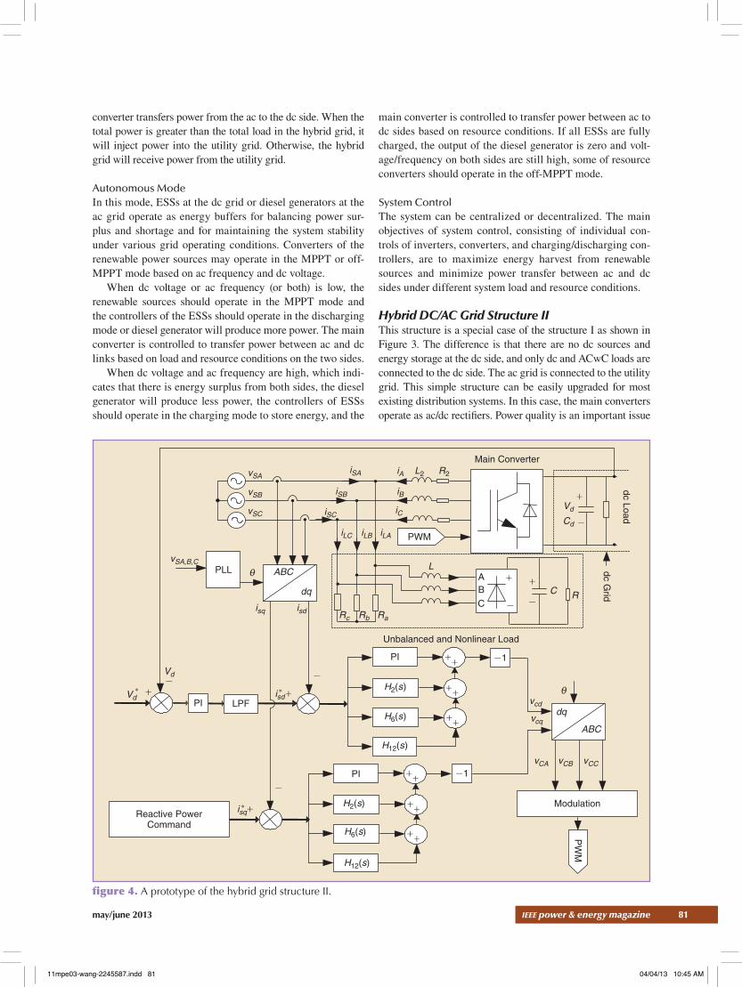
Hybrid DC/AC Grid Structure II this structure is a special case of the structure I as shown in Figure 3. the difference is that there are no dc sources and energy storage at the dc side, and only dc and acwc loads are connected to the dc side. the ac grid is connected to the utility grid. this simple structure can be easily upgraded for most existing distribution systems. In this case, the main converters operate as ac/dc rectifiers. Power quality is an important issue
Reactive PowerCommand
i
i
*
* *
Main Converter
Vd
L2iAiSAvSA
vSC
vSB iSB iB
iCiSC
iLC
isq
Vd
Vd
isd
isd+
isq+
iLB iLA
R2
Cd
L
Unbalanced and Nonlinear Load
dq
H12(s)
H12(s)
H2(s)
ABCPLLvSA,B,C
RaRbRc
H6(s)
H6(s)
H2(s)
PI
PI
PI
AC R
vCCvCBvCA
vcq
vcd
B
C
LPF
-
-
--
-
-1
-1
-
++
+
+
+
++
++
++
++
+
++
ABC
dq
Modulation
PW
M
PWM
dc Load
dc Grid
figure 4. A prototype of the hybrid grid structure II.
11mpe03-wang-2245587.indd 81 04/04/13 10:45 AM

82 ieee power & energy magazine may/june 2013
in the local distribution system with the increased penetration of nonlinear loads due to their harmonic current injection into the grid. one of the main functions of the main converter is to control the harmonic injection to the ac bus. moreover, three-phase unbalanced loads are ubiquitous in distribution systems and can cause large negative sequence currents. the polluted grid current will increase the loss and reduce the efficiency of the network. therefore the second function of the main con-verter is to compensate harmonic and reactive power as well as unbalanced loads on the ac side. a prototype of the hybrid grid structure II and its control block diagram are shown in Figure 4. the ac grid is represented by three-phase voltage sources vSA, vSA and vSA. Unbalanced three-phase ac distribution with har-monics is represented by an unbalanced and nonlinear load. the output of the main converter is the dc grid. the structure will provide a clean and balanced three-phase current.
Main Advantages of Hybrid AC/DC GridsFrom the analysis, multiple conversions have been reduced to a minimum due to both dc and ac links in the hybrid structure. the advantages of the hybrid grid can be summarized as follows:
✔ the elimination of unnecessary multiconversion pro-cesses means a reduction of total conversion loss.
✔ the elimination of embedded rectifiers for dc and acwc loads in the current ac grid means the simplification of equipment and cost reduction of electronic products.
✔ the connection of all dc loads to the dc side of the hybrid grid will make it easy to control harmonic injections into the ac side through the main converters, thus guaranteeing high-quality ac in the utility grid.
✔ the dc grid can solve negative and zero sequence current problems caused by unbalanced loads in ac distribution systems, and the neutral wire in subtransmission may be eliminated and the related transmission losses reduced.
Existing DC and Hybrid DC/AC Gridsthere are several dc and hybrid grids that have been pro-posed and tested for industrial systems, commercial facili-ties, residential buildings, and data centers around the world. the efficiency of dc and ac transmission and distribution considering multiconversions has been compared. the loss of dc transmission is lower than that of ac, and dc grids also have less of a conversion process compared with ac. When combining both ac and dc in local distribution systems, the conversion process can be further reduced to a minimum. two pioneering demonstrations of dc systems have been tested at the Lawrence berkeley national Laboratory, with 10% energy savings recorded for the entire data center, com-pared to a very efficient ac baseline case.
a hybrid dc/ac grid is under construction at the Water and energy research Laboratory (WerL) with support from schneider electric singapore and nanyang technological
ToOther Grid
ToUtility Grid
4.5-kWProg LoadNetwork
Impendance
NetworkResistor
18-kW acProg Source
ac:400 V
dc:380 V
To Panel 8
Panel 1
To Panel 8
Panel 8
ToPanel 1
To Panel1
Panel 8Panel 1
ac/dcConverter
ac/dcBidirectionalConverter
dc/dc Converterdc/dc
Converter
dc/dcConverter
dc/dcConverter
dc/dcConverter
ac/dcBidirectionalConverter
ac/dcConverter
3.3-kW ResistLoad
Electrolyzer
Fuel CellTank
Generator
EMS/SCADA
5-kWpPV System
14.5-kWProg Load
Lithium IonBatteries
192-V–150-AHLead AcidBatteries
1.45-kWSolar ArraySimulator
20-kW dcProg
Source
Modbus TCP/IP
7.5-kW WTGSimulator
3.3-kWResist Load
figure 5. A hybrid ac/dc microgrid at the WERL, NTU.
11mpe03-wang-2245587.indd 82 04/04/13 10:45 AM

may/june 2013 ieee power & energy magazine 83
University (ntU), singapore. the illustration diagram of the hybrid ac/dc grid is shown in Figure 5. the hybrid grid consists of a 400-v, three-phase ac grid with eight nodes and a 380-v dc grid with eight nodes. both ac and dc grids can be connected into radial or ring configurations. two bidirectional converters tie ac and dc grids together. an 18-kW ac source, 7.5-kW wind turbine generator simulator, 4.5-kW programmable load, and 3.3-kW resistive load are connected to the ac grid. the ac grid can also be connected to the utility grid and to the ac mG in the ntU clean energy research laboratory. a 20-kW dc program-mable source, 14.5-kW programmable load, a 3.3-kW resistive load, 1.45-kW solar simulator, and 28.8-kWh battery storage are connected to the dc grid. a 5-kW Pv system can be connected to the ac grid by a dc/ac grid tied inverter and can also be switched to the dc grid through a dc/dc booster converter. a 1.2-kW fuel cell generator with a 5-kWh hydrogen tank as energy storage is connected to the ac grid and can also be switched to the dc grid. the illustrative hybrid system is shown in Figure 5.
the aim of this hybrid grid is to provide a test bed for ✔ investigating different hybrid grid infrastructures ✔ studying the individual and coordination control tech-nologies for various inverters and converters
✔ testing suitable voltage levels for the dc grid, which can facilitate the connection of various dc sources and dc loads
✔ investigating new problems due to the connection of dc sources and loads
✔ developing new inverters and converters for reliable operation of the hybrid grid
✔ testing newly developed dc protection and metering equipment
✔ developing energy management system(s) for hybrid mGs.
Problems to Be Solved for Future Implementation although the hybrid grid can reduce the unnecessary processes of dc/ac and ac/dc conversions compared with an individual ac or dc grid, many practical problems exist for implementing it. It is not economical and also difficult to build a new dc grid to replace the existing ac distribution infrastructure. It takes time to find the right way to upgrade the current ac distribution sys-tems into hybrid ac/dc grids. the second problem is to define standard voltages for the dc grid. standard dc voltages have to be determined for easy connection of popular dc loads consid-ering the current ac voltages. besides hybrid infrastructures, home and office products also will have to be redesigned with-out the embedded ac/dc rectifiers. therefore it is a long-term process for the implementation of the hybrid ac/dc grid. the hybrid grids can be easily implemented in new buildings. For the old buildings that need to upgrade distribution systems due to the integration of Pv systems, new LeD lighting systems, and ev charging systems, there exists a good opportunity to use the hybrid grid. new metering, protection, and grounding equipment are also required for the hybrid grid.
ConclusionFor over 100 years, ac power systems have developed and expanded to today’s scale and have provided tremendous power and convenience for the rapid advancement of modern society. electrical engineers have become used to building various embedded conversion converters for various loads to adapt to ac. Problems that have come to the fore due to global warming and limited fossil fuel resources require electrical engineers to rethink about efficiency of energy utilization for conventional ac power systems and to reexamine cur-rent ac transmission and distribution structures. although it is difficult to implement this new structure in current ac-dominated local distribution systems, hybrid ac/dc grids and hybrid energy grids with dc/ac/thermal will be the future for high-efficiency energy supply systems. Dc and ac systems coexisting in harmony due to advanced power electronic techniques will provide more green and high quality energy with the highest efficiency.
For Further Readingm. e. baran and n. r. mahajan, “Dc distribution for indus-trial systems: opportunities and challenges,” IEEE Trans. Ind. Appl., vol. 39, no. 6, pp. 1596–1601, nov. 2003.
a. sannino, G. Postiglione, and m. h. J. bollen, “Fea-sibility of a dc network for commercial facilities,” IEEE Trans. Ind. Appl., vol. 39, no. 5, pp. 1409–1507, sept. 2003.
D. salomonsson and a. sannino, “Low-voltage dc distri-bution system for commercial power systems with sensitive electronic loads,” IEEE Trans. Power Delivery, vol. 22, no. 3, pp. 1620–1627, July 2007.
m. ton, b. Fortenbery, and W. tschudi. Dc power for im-proved data center efficiency. Lawrence berkeley national Laboratory, ca [online]. available: http://hightech.lbl.gov/dc-powering/
D. J. hammerstrom, “ac versus dc distribution systems: Did we get it right?,” in Proc. IEEE Power Engineering Society General Meeting, June 2007, pp. 1–5.
X. Liu, P. Wang, and P. c. Loh, “a hybrid ac/dc micro-grid and its coordination control,” IEEE Trans. Smart Grid, vol. 2, no. 2, pp. 278–286, 2011.
P. Wang, X. Liu, c. Jin, P. c. Loh, and F. choo, “a hy-brid ac/dc micro-grid architecture, operation and control,” in Proc. 2011 General Meeting IEEE Power Engineering Society, Detroit, mI.
BiographiesPeng Wang is with nanyang technological University, singapore.
Lalit Goel is with nanyang technological University, singapore.
Xiong Liu is with nanyang technological University, singapore.
Fook Hoong Choo is with nanyang technological Univer-sity, singapore.
p&e
11mpe03-wang-2245587.indd 83 04/04/13 10:45 AM