harmony® fabrication quick guides -...
TRANSCRIPT

Harmony® Fabrication Quick Guides These Quick Guides describe the 12 Harmony® fabrication steps. Follow them in the order they are presented to minimize fabrication time. The first Quick Guide describes how to vacuum cast since not all prosthetists are familiar with this technique. The next nine Quick Guides (Steps 1–9) describe how to fabricate the temporary (test socket) Harmony® system.
1. Casting for custom urethane liner 2. Casting for socket 3. Reducing positive mold 4. Marking trim lines and pulling test socket 5. Checking fit of socket 6. Assembling the prosthetic leg 7. Creating vacuum 8. Lowering trim lines and installing gaiter 9. Aligning the prosthesis
The last three Quick Guides (Steps 10–12) describe how to fabricate the definitive socket and an optional protective slip cover, and how to vent the pump outside a cosmetic cover.
10. Making definitive socket 11. Making protective slip cover 12. Cosmetic cover modification
Full size masters of a worksheet and four charts that you might want to duplicate can be found following the Quick Guides.
• Mold Reduction Worksheet • 4% Reduction Chart • 5% Reduction Chart • 6% Reduction Chart • Elastomer Rod Adjustment Chart
© 2006 Otto Bock HealthCare LP

Harmony® Fabrication Quick Guides 2
Vacuum Casting
1. Pull 2–4 layers of nylon stockinet or a casting sock over the wet plaster for an air wick. Be sure to leave extra material at the distal end. This will ensure that the vacuum line has an air wick when it is pressed up against the bottom of the limb.
2. Select a casting bag (small, medium or large) that is
small enough to seal proximally, but large enough to provide ample room for the limb. A snug casting bag should not be used since it can deform the limb and prevent the vacuum from extending proximally. The bag may extend beyond the end of the limb as shown.
3. Spray a 50%/50% mix of water and alcohol into the
inverted bag before rolling it on, if you would like to reduce friction.
4. Attach the vacuum line to the connector at the distal end of the bag. Push and hold the vacuum line against the air wick so that air can be removed from the bag.
5. Support soft tissues if needed before turning on the
casting pump. Vacuum holds the soft tissues in their
current shape. So, if needed, gently support tissues before turning on the casting pump.
6. Seal the casting bag proximally, turn on the casting pump (>51 kPa, 15” Hg) and maintain vacuum until the cast has set. Don’t worry about folds in the bag. They will not affect the quality of the cast.
Wet plaster cast
Nylon stockinet or casting sock
Extra material
Important: If the bag isn’t being pulled down tightly against the limb, look for the following causes and use the respective solution. 1. Vacuum line is sealed off against the inside of the bag.
Solution: Turn off the pump, reposition the vacuum line so that is in direct contact with the stockinet and turn the pump back on.
2. Casting bag is too snug, causing it so seal off distally on the leg. Solution: Use a larger casting bag.
3. Air wick is saturated with wet plaster. Solution: Add additional layers of air wick.
Remember to empty the water trap on the casting pump after vacuum casting. Required Materials and Tools Nylon stockinet Casting sock Casting bags 50/50% alcohol/water mix Casting pump
Casting bag
© 2006 Otto Bock HealthCare LP

Harmony® Fabrication Quick Guides 3
Step 1 – Casting for Custom Urethane Liner
1. Complete all required sections of the Order Form, including limb circumferences. Indicate on the Order Form that you are requesting a custom Harmony® liner.
Cast from this mark down
2. Apply parting agent to the limb, stopping ~20 cm (8”) above the top of the patella. Normal Skin: Wrap the limb with plastic wrap or cover with lubricant. Abnormal Skin (Non-closing Invagination or Scaring): Invaginations or deep scaring that do not close when cupped by hand are rare; only 1–2% of all patients. If you encounter one of these cases, fill the invagination/scar with plaster bandage wrap. Apply lubricant to the remainder of the limb. Avoid getting lubricant on the bandage wrap. Make a note on the Order Form to alert Otto Bock of the invagination/scar.
3. Pull a thin casting sock over the limb to a height of ~20 cm (8”) above the top of the patella.
4. Mark the bottom of the patella on the casting sock
with an indelible pencil. This mark is used by the Otto Bock technician when manufacturing the custom liner.
5. Mark a spot on the thigh 9” above the mark at the
bottom of the patella as a reference for the top of the cast. Have the patient hold their limb at 10 degrees of flexion.
6. Cast the limb with plaster bandage starting proximally
at the mark.
7. Apply 4 layers of nylon or a casting sock over the cast.
8. Apply casting bag. Extend it up to the thigh to form a
seal.
20 cm (8”)
9. If necessary, lightly support any distal, redundant soft tissue that gravity has caused to droop so that it remains in line with the rest of the lower limb until the plaster has set. The reason to support the soft tissue is to avoid producing a liner that tends to hold soft tissue off center.
Keeping tissues inline
10. Place the knee at 10 degrees of flexion and turn on the
casting pump. Maintain vacuum until the cast has set. 11. Write the patient’s name on the cast. 12. Ship the cast and completed order form to Otto Bock.
© 2006 Otto Bock HealthCare LP

Harmony® Fabrication Quick Guides 4
Step 1 – Casting for Custom Urethane Liner
If you ha e any questions about how to handle non-closing vinvaginations/scars please contact Otto Bock. Required Materials and Tools
stic wrap or lubricant Order form PlaCasting sock Indelible pencil Knee angle to Non-elastic plaster baol ndage Nylon stockinet Casting bags Casting pump Water bucket Gloves
© 2006 Otto Bock HealthCare LP

Harmony® Fabrication Quick Guides 5
Step 2 – Casting for Socket
1. Cast in the morning before the limb loses volume if possible.
2. Examine the limb for characteristics that might influence how you cast the limb. Note the locations of the patella, femoral condyles, tibial tuberosity, fibular head, distal ends of the tibia and fibula, skin anomalies, neuromas and any other points of interest. Also hold the limb and have the patient contract his/her calf muscles to determine whether and how much shape change the muscles cause.
3. Find and mark the anterior midline of the new liner with a permanent marker to aid the patient when donning the liner. The patient’s name is lightly inscribed inside the liner at its distal, posterior aspect.
4. Have the patient don the liner and remove all air
between the limb and liner.
5. Apply a parting agent such as lubricant or plastic wrap
to the liner; stopping ~5 cm (2”) from the top of the liner. The exposed portion of the liner will seal with the casting bag.
6. Roll one layer of nylon stockinet or a casting sock
over the parting agent.
7. Determine which size casting bag will be used. The
bag should seal with the top 5 cm (2”) of the liner but be loose over the remainder of the limb.
Stage 1 – Capture femoral condyles 8. Create a 7.5 cm (3”) wide plaster splint that is 4–6
layers thick as shown. Cut it to a length so that it will go from the medial to the lateral midline of the limb, but not so long as to cover the fibular head. Notch the central section of the splint so that the center section is ~4 cm (1.5”) wide. This narrow center section should reside between the bottom of the patella and tibial tuberosity.
Mark the anterior midline of the liner
A = 7.5 cm (3”) B = Extends from medial to lateral
midlines of tibia C = Distance (~4 cm (1.5”))
between bottom edge of patella and tibial tuberosity
A
B
C
Liner
9. Wet the splint and position it on the limb to capture
the femoral condyles. The narrow midsection should be positioned between the bottom edge of the patella and the tibial tuberosity. Make sure the top of the splint is aligned with the bottom edge of the patella. This is important because the splint’s top edge is used later to identify the height to which the mold is reduced.
Plastic wrap 5 cm (2”)
10. Pull on two layers of nylon stockinet or a casting sock
for an air wick as shown. Vacuum cast the splint, with the knee in 80° of flexion. Seal the bag with the
© 2006 Otto Bock HealthCare LP

Harmony® Fabrication Quick Guides 6
Step 2 – Casting for Socket
proximal liner. Draw a vacuum of at least 51 kPa (15” Hg) when casting.
11. Once the plaster sets, make sure the splint stays in
position as you remove the casting bag and two layers of stockinet/casting sock.
Stage 2 – Capture prominent bony features 12. Cut a second 4–6 layer splint as shown in the
following picture to capture the tibial crest and fibular head. Its width should extend from the medial to lateral midlines of the limb except in the area of the fibular head; in this area the splint should extend posteriorly to capture the entire head of the fibula. Do not extend the splint into the soft tissues posteriorly. The height of the splint should allow it to extend from the center of the patella to 3–6 mm (1/8 – 1/4”) proximal of the end of the tibia.
13. Wet the splint and position it on the limb to capture
the prominent anterior bony features and the fibular head. Pull on two layers of nylon stockinet or a casting sock for an air wick as shown.
15. ers
Once the plaster sets, make sure the splint stays in position as you remove the casting bag and two layof stockinet/casting sock. LIGHTLY
press here so the bottom edge of the patella is identifiable
St16. the
ork distally.
17. k
befo
18. e the soft tissue droops
down and causes a step at the distal end of the tibia, lightly support the tissues before pulling vacuum to eliminate the step.
19. If the patient’s calf muscles when tensed noticeably
change the shape of the limb, have the patient tense the calf muscles prior to and during vacuum casting.
age 3 – Capture limb volume With the knee still at 5–10° of flexion, plaster wrapentire limb (and 2 previous splints) from
14. Vacuum cast with the knee at 5–10° of flexion.
approximately 2.5 cm (1”) above the top edge of thepatella down to the distal end of the limb. Start wrapping proximally and w
Apply 4 layers of nylon stockinet or a casting socover the cast for an air wick and vacuum cast as
re.
In the occasional case wher
Eliminating tibial step
A = center of patella down to 3-6 mm (1/8-1/4”) proximal of the end of the tibia B = Extends from medial to lateral midlines C = Extension to capture fibular head
A
B C
© 2006 Otto Bock HealthCare LP

Harmony® Fabrication Quick Guides 7
Step 2 – Casting for Socket
20. Apply vacuum. Once the plaster sets, remove the casting bag and four layers of stockinet or casting sock. Slide the cast off the limb.
Required Materials and Tools Permanent marker Skin lotion Urethane liner Lubricant or plastic wrap Nylon stockinet Casting sock Casting bags Non-elastic plaster bandage Scissors Casting pump Gloves Bucket of water
© 2006 Otto Bock HealthCare LP

Harmony® Fabrication Quick Guides 8
Step 3 – Reducing Positive Mold
When reducing, always maintain the shape of the limb! 1. Pour plaster into the negative cast. Imbed whatever
type of anchoring post/adapter your facility normally uses. An embedded metal pipe is illustrated here.
2. Remove the poured plaster mold by cutting the back
of the 3-stage cast where it is only one layer thick. 3. Punch a 6 mm (¼”) deep hole into the mold with an
awl at the bottom edge of the patella. Press an indelible pencil into the hole.
4. Measure from the top of the mold down to the bottom
edge of the patella (hole you just punched) and record this distance on the top of the mold should it be needed later.
5. Punch and mark 3–5 additional anterior, 6 mm (¼”) deep holes distal to the proximal hole (A). These will serve as marks at which circumferences will be measured. The most distal mark should be well short of the sharp curvature at the end of the mold.
6. Punch and mark five 6 mm (¼”) deep holes on the
distal end of the mold; one at the center and four slightly off center; one each in the medial, lateral, anterior and posterior directions. Use a lead pencil to
mark these holes. Lead pencils will not bleed into the plaster, which is important here since you need to shave the distal end down by 6 mm (¼”) and no more.
Hole pattern in end of mold
Pipe
3-stage cast
Poured plaster
7. Using a rasp, carefully reduce the end of the mold
until the five 6 mm (¼”) deep marks just disappear. 8. Measure and record in millimeters the mold
circumferences at each of the anterior marks in the “Starting Circ (mm)” column in the following worksheet.
Mold Reduction Worksheet
Patient Name: Date:
Marks
Starting Circ (mm)
Target Circ (mm)
Starting Minus Target
Rasp
Strokes A B C D E F G
9. Calculate the 4, 5 or 6% reduced circumferences by multiplying each circumference by 0.96, 0.95 or 0.94, respectively, or by using one of the following tables. We recommend reducing by 4 % when first making Harmony® systems. As you become more experienced, you may find that you need to reduce by 5 or 6%. The reduction should include the final smoothing (screening) of the mold. A B C D
© 2006 Otto Bock HealthCare LP

Harmony® Fabrication Quick Guides 9
Step 3 – Reducing Positive Mold
4% Reduction Chart Circ -4% Circ -4% Circ -4% 205 197 305 293 405 389 210 202 310 298 410 394 215 206 315 302 415 398 220 211 320 307 420 403 225 216 325 312 425 408 230 221 330 317 430 413 235 226 335 322 435 418 240 230 340 326 440 422 245 235 345 331 445 427 250 240 350 336 450 432 255 245 355 341 455 437 260 250 360 346 460 442 265 254 365 350 465 446 270 259 370 355 470 451 275 264 375 360 475 456 280 269 380 365 480 461 285 274 385 370 485 466 290 278 390 374 490 470 295 283 395 379 495 475 300 288 400 384 500 480
5% Reduction Chart
Circ -5% Circ -5% Circ -5% 205 195 305 290 405 385 210 200 310 295 410 390 215 204 315 299 415 394 220 209 320 304 420 399 225 214 325 309 425 404 230 219 330 314 430 409 235 223 335 318 435 413 240 228 340 323 440 418 245 233 345 328 445 423 250 238 350 333 450 428 255 242 355 337 455 432 260 247 360 342 460 437 265 252 365 347 465 442 270 257 370 352 470 447 275 261 375 356 475 451 280 266 380 361 480 456 285 271 385 366 485 461 290 276 390 371 490 466 295 280 395 375 495 470 300 285 400 380 500 475
6% Reduction Chart
Circ -6% Circ -6% Circ -6% 205 193 305 287 405 381 210 197 310 291 410 385 215 202 315 296 415 390 220 207 320 301 420 395 225 212 325 306 425 400 230 216 330 310 430 404 235 221 335 315 435 409 240 226 340 320 440 414 245 230 345 324 445 418 250 235 350 329 450 423 255 240 355 334 455 428 260 244 360 338 460 432 265 249 365 343 465 437 270 254 370 348 470 442 275 259 375 353 475 447 280 263 380 357 480 451 285 268 385 362 485 456 290 273 390 367 490 461 295 277 395 371 495 465 300 282 400 376 500 470
10. Starting with approximately 4 strokes, work your way
around the mold until the reduced circumferences are attained. Do not reduce the mold above the height of the proximal mark (A). Be careful to take fewer or less aggressive strokes of the rasp distally where the molds usually are smaller in diameter. Maintain the shape of the limb as you reduce. Be sure to maintain the exact shapes of the bony prominences, such as the fibular head and distal tibia, when reducing them. Caution: It is easy to remove too much plaster from small prominences such as the fibular head.
Optional: It is instructive to record the number of millimeters by which the circumferences were reduced. You may record these in the rightmost column in the worksheet and count the number of rasp strokes it took you to create these reductions. Noting these two things allows you get a feel for how many strokes it will take to achieve various reductions in the future. 11. Distally, make sure there is a smooth transition
between the sides and end of the mold by creating a smooth radius.
12. Blend the un-reduced (proximal) portion of the mold with the reduced portion.
13. Smooth the mold with a sanding screen.
© 2006 Otto Bock HealthCare LP

Harmony® Fabrication Quick Guides 10
Step 3 – Reducing Positive Mold
14. Double check your circumferences after using the sanding screen.
Required Materials and Tools Gloves Plaster Water Anchoring post/adapter Utility knife Awl Indelible and lead pencils Tape measure Calculator Paper Half round rasp Full round rasp Sanding screen
© 2006 Otto Bock HealthCare LP

Harmony® Fabrication Quick Guides 11
Step 4 – Marking Trim Lines and Pulling Test Socket
1. All trim lines are measured from a circumferential line drawn at the height of the bottom edge of the patella. Place the top edge of a rubber band around the mold at the bottom edge of the patella. Draw a line along the top edge of the rubber band with an indelible pencil. Remove the rubber band.
Lateral hamstring
tendon
Medial hamstring tendons
Major vessels and
nerves
Rubber band
2. Mark the height of the anterior trim line; 40 mm (1.5”) above the reference line as shown below.
3. Mark the heights of the medial and lateral trim lines; 50 mm (2”) above the reference line as shown below.
4. Mark three points to identify the heights of the posterior trim liner. At the midline, measure and mark a point 6 mm (¼”) above the reference line. This should be directly posterior from the center of the patella. For hamstring relief, measure and mark two points 6 mm (¼”) below the reference line, one for each hamstring. Be sure the two hamstring points are positioned anatomically correct.
Be aware of the posterior anatomical structures as you make these points.
5. Connect the points with an indelible pencil by drawing
curved lines. The trim lines should appear as follows. Note how the medial and lateral trim lines drop down sharply so that they don’t wrap around posteriorly.
Medial/lateral Posterior Anterior
Lat Med
6. Place reduced mold upside down in a vacuum stand.
Vacuum line
Vacuum stand
Medial/lateral Posterior Anterior 40 mm (1.5”)
50 mm (2”)
6 mm (1/4”)
Lat Med Reference
line 7. Heat a square of clear plastic (Thermolyn Stiff
616T52) to 170 C° (350 F°) in an oven for approximately 15 minutes or until it droops 1/3 – 1/2 of the height of the mold.
8. Slowly pull the plastic over the mold down and apply vacuum.
© 2006 Otto Bock HealthCare LP

Harmony® Fabrication Quick Guides 12
Step 4 – Marking Trim Lines and Pulling Test Socket
Vacuum line
Vacuum stand
9. Once the plastic has cooled, transfer the trim lines to
the test socket. 10. Remove the test socket from the mold and cut the test
socket along the trim lines. 11. Clean up the sharp edges of the test socket. Required Materials and Tools Rubber band Indelible pencil Tape measure Clear plastic sheet Oven Vacuum stand Vacuum source Insulated mittens Permanent marker Cast saw Sander/buffer Thermolyn stiff (616T52)
© 2006 Otto Bock HealthCare LP

Harmony® Fabrication Quick Guides 13
Step 5 – Checking Fit of Socket
There are three checks to determine fit: 1) Total contact 2) Progressive liner drive 3) Patient comfort
These three checks are performed before anything is attached to the clear socket so that the entire liner is visible. To prepare for the three checks: 1. Have your patient doff the liner. 2. With a permanent marker, draw 12 vertically aligned
dots on the outside of the liner; 3 anteriorly, 3 medially, 3 laterally and 3 posteriorly. The top dots should be at least 4 cm (1.5”) below the posterior trim line.
3. Set the liner into the test socket and circle the 12 liner
dots on the outside of the socket.
4. Have the patient don the liner and sheath.
Check 1 – Total contact 5. Have the patient stand in the socket using a floor
stand. Visually inspect to make sure the donned liner makes total contact with the socket. Anterior
midline mark on liner
Anterior, medial and lateral sets of dots
Floor Stand
Check 2 – Progressive Liner Drive 6. Inspect the proximal flow of the 12 liner dots while
they are standing with half body weight on the floor stand. The dot (liner) drive should be progressively more in the proximal direction as shown. It is the pattern of liner (dot) drive that should be your focus, more than the absolute amount of drive. The dot movements listed are rough estimates. Focus on the liner drive pattern, not the absolute amounts of the dot movements.
© 2006 Otto Bock HealthCare LP

Harmony® Fabrication Quick Guides 14
Step 5 – Checking Fit of Socket
Floor Stand
~13-19 mm (1/2-3/4”)
~6-10 mm (1/4-3/8”)
~10-16 mm (3/8-5/8”)
If the liner drive pattern is not progressive as pictured see the “Harmony® Troubleshooting Table for the Prosthetist” for instructions on how to interpret your drive pattern and use fillers to establish a proper liner drive pattern. If you have to add a full sock to establish proper liner drive, you should make a new socket. Check 3 – Patient Comfort 7. Ask your patient if the fit is snug and comfortable. If
the patient experiences pain or discomfort, see the “Harmony® Troubleshooting Table for the Prosthetist.”
If you reduced the fibular head too much and the patient is complaining of fibular head pressure, it can be resolved by having the patient stand in the socket after heating it up in the fibular head region. • Make a dot on the sheath where they feel discomfort. • Have them stand in the socket and draw a 5 cm
diameter circle around the dot. • Remove the socket and heat it at the circle. • Have them stand in the heated socket. Required Materials and Tools Permanent marker Tape measure Floor stand
© 2006 Otto Bock HealthCare LP

Harmony® Fabrication Quick Guides 15
Step 6 – Assembling the Prosthetic Leg
In this step, you will be assembling the leg and attaching it to the test socket. Attach the leg in the order (bottom-up or top-down) in which your lab is accustomed. The top-down approach is described here. If you prefer the opposite approach, start at the foot and work up. Before you start, note the tilt of the socket as they stand on 1. Attach an adapter (6A94=3 or 5R1=6 or 4R111) to the
bottom of the socket. Keep in mind your patient’s unique alignment when attaching the adapter. In general you want to glue the adapter in a position where the pyramid adjustment screws will be in their neutral positions. Three methods are shown below. Select the one your facility prefers. A. TEC Plate Adapter Method. Set the adapter on the table so the four notches are up and the four hole pattern is oriented correctly. Place Loctite® Adhesive 454 into the center of the TEC plate adapter (6A94=3). Lightly spray the bottom of the socket with Loctite® Accelerator 712 to promote rapid curing. Set the socket on the TEC plate adapter.
B. Wooden Adapter Method. Place a temporary collar around the distal end of the socket and spray foam into the collar. Once the hard foam has cured, sand it flat to accept the wooden socket adapter (5R1=6) so it is properly aligned. Use sealing resin to bond the 5R1=6 to the sanded foam.
C. Four Prong Adapter Method. Bend the four prong adapter (4R111) to match the shape of the bottom of the socket. Bond the adapter to the botto
of the socket with acrylic putty. If flat head screw are used to strengthen the connection between the socket and adapter, be sure to use clear pressure sensitive tape(616F22) to cover the screw heads on the inside of the socket. This will prevent vacuum leaks.
m
2. Use 50 mm (2”) fiberglass casting tape to fill the ap
3.
4. 0° filtered barbed fitting (4Y350) in the
gbetween the adapter and socket if it exists. Continue by tightly wrapping the fiberglass casting tape aroundthe adapter (6A94=3 or 5R1=6) and distal end of the socket as shown in the drawing. Wrap a minimum of 75–125 mm (3–5”) up from the bottom of the socket to secure the adapter to the socket. If possible, leave aminimum of 65 mm (2.5”) of the socket exposed between the posterior trim lines and top of the fiberglass wrap for sealing purposes.
If you were unable to leave at least 65 mm (2.5”) of the socket free of fiberglass tape, tightly wrap clear pressure sensitive tape (616F22) over the fiberglass before it cures. This will extend the surface onto whichthe sealing sleeve can seal. While the clear pressure sensitive tape provides an imperfect sealing surface, it is considerably better than the fiberglass casting tape alone. Install a 9distal, posterior-medial aspect of the socket. This location reduces the risk of the barbed fitting beingbumped. If needed, grind through fiberglass/foam toexpose a 12 mm (½”) circular area of the socket in which to thread the barbed fitting.
Apply acrylic putty
Bond adapter
Adhesive
Accelerator
If possible, >2.5” (65 mm)
3-5” (75-125 mm)
Pour foam
Sand foam
Bond 5R1=6
© 2006 Otto Bock HealthCare LP

Harmony® Fabrication Quick Guides 16
Step 6 – Assembling the Prosthetic Leg
5. In the circular area, drill a hole through the socket wall
using a 6 mm bit and use the barbed fitting as a tap by threading it into the hole. Or use bit #3 and thread the hole with a ¼”–28 tap.
6. Before using epoxy, thread the barbed fitting into the hole to determine whether a washer is needed to prevent the barbed fitting from protruding into the socket.
7. Epoxy the threads and thread the barb fitting into the socket wall. Avoid getting epoxy in either end of the barbed fitting.
8. Attach the Harmony® pump to the adapter.
9. Using the following table, adjust the elastomer rod
found inside the distal shaft of the Harmony® pump to your patient’s weight. This initial adjustment should ensure that the pump displacement during walking is close to what is needed for the pump to create a vacuum of at least 51 kPa (15” Hg). Final adjustment of the elastomer rod will be made later. Using a 10
mm hex wrench, turn the screw located in the bottom of the pump as far as possible in the clockwise direction.
Ground down to socket
Medial Lateral
10 mm hex
Back the same screw out counter clockwise the number of full turns listed in the following table according to your patient’s weight and the pump being used. If you installed a red rod into an HD pump, use the P2 Pump column.
© 2006 Otto Bock HealthCare LP

Harmony® Fabrication Quick Guides 17
Step 6 – Assembling the Prosthetic Leg
Loctite® 454 adhesive Loctite® 712 accelerator Tape measure Pressure sensitive tape
Patient Weight (kg/lbs)
P2 Pump (4R144) Red Rod
HD Pump (4R150)
Yellow Rod 50/120 4.5 - 60/140 4.0 - 70/160 3.5 - 80/180 3.0 - 90/200 2.5 -
100/220 2.0 4.5 110/240 - 4.0 120/260 - 3.5 130/280 - 3.0 140/300 - 2.5 150/320 - 2.0
Sander TEC plate (6A94=3) Wooden adapter (5R1=6) 4 prong adapter (4R111) Drill bit 6 mm or #3 ¼–28 tap 5 minute epoxy Right angle barbed fitting 4 mm hex wrench 10 mm hex wrench 5 cm (2”) fiberglass casting tape
Important: Never back the screw out more than 5 full turns, as this may compromise pump function. 10. Assemble the remainder of the prosthetic leg and
adjust its length so that the pelvis is level.
Required Materials and Tools
© 2006 Otto Bock HealthCare LP
Harmony® Fabrication Quick Guides 18
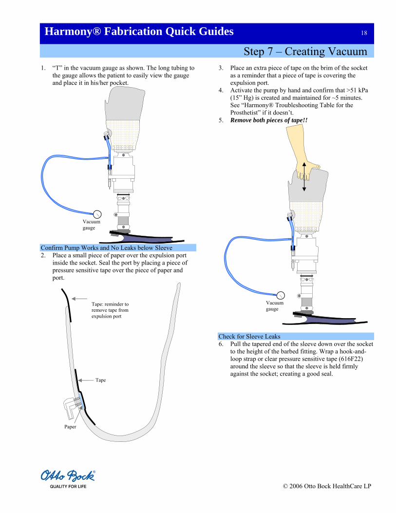
Step 7 – Creating Vacuum
1. “T” in the vacuum gauge as shown. The long tubing to the gauge allows the patient to easily view the gauge and place it in his/her pocket.
Confirm Pump Works and No Leaks below Sleeve 2. Place a small piece of paper over the expulsion port
inside the socket. Seal the port by placing a piece of pressure sensitive tape over the piece of paper and port.
3. Place an extra piece of tape on the brim of the socket as a reminder that a piece of tape is covering the expulsion port.
4. Activate the pump by hand and confirm that >51 kPa (15” Hg) is created and maintained for ~5 minutes. See “Harmony® Troubleshooting Table for the Prosthetist” if it doesn’t.
5. Remove both pieces of tape!!
Vacuum gauge
Vacuum gauge
Tape
Paper
Tape: reminder to remove tape from expulsion port
Check for Sleeve Leaks 6. Pull the tapered end of the sleeve down over the socket
to the height of the barbed fitting. Wrap a hook-and-loop strap or clear pressure sensitive tape (616F22) around the sleeve so that the sleeve is held firmly against the socket; creating a good seal.
© 2006 Otto Bock HealthCare LP

Harmony® Fabrication Quick Guides 19
Step 7 – Creating Vacuum
7. Deflect the top portion of the sleeve down over the
socket and pump. Have the patient don the liner and sheath, and slide into the socket. Lubricate the exposed portion of the liner with lubricant to improve its seal with the sleeve. If you don’t do this the system will usually leak slowly.
Apply lubricant to this exposed
surface of the liner
© 2006 Otto Bock HealthCare LP

Harmony® Fabrication Quick Guides 20
Step 7 – Creating Vacuum
8. Roll the sleeve up over the socket, liner and thigh.
9. Slide the o-ring up as high as possible on the distal shaft of the pump. Then have the patient take several steps. The o-ring should displace down the shaft ~6 mm (¼”).
Harmony® HD
Harmony® HD
Slide o-ring all the way up the shaft
before the subject walks
O-ring displacement after walking; should be
~6mm (¼”)
O-ring
10. If the o-ring displaced much less then 6 mm (¼”),
remove the pylon and turn the 10 mm (3/8”) elastomer rod screw counterclockwise. If the o-ring displaced much more than 6 mm (¼”), turn the screw clockwise.
11. Have the patient take ~40 steps. The vacuum gauge should read at least 51 kPa (15” Hg) and stay unchanged for at least 5 minutes. A reading of 78 kPa (23” Hg) is commonly seen with the Harmony® mechanical pumps. If vacuum isn’t created and maintained, see the “Harmony® Troubleshooting Table for the Prosthetist”.
Required Materials and Tools T connector Tubing Vacuum gauge Pressure sensitive tape Paper Lubricant Sleeve Hook-and-loop strap 4 mm hex wrench 10 mm hex wrench
© 2006 Otto Bock HealthCare LP

Harmony® Fabrication Quick Guides 21
Step 8 – Lowering Trim Lines and Installing Gaiter
Lowering Trim Lines 1. Completely remove the sleeve from the socket. 2. With the patient still standing, make a mark on the
socket 1/3 – 1/2 of the way up from the bottom of the patella.
3. With the patient still standing in the socket, palpate the
tops of the medial (adductor tubercle) and lateral femoral epicondyles. Mark the tops of these epicondyles on the sides of the socket.
4. Have the patient don the sealing sleeve and walk or step in place until a vacuum >51 kPa (15” Hg) is created. With the patient sitting and the knee fully extended, place your finger on top of the center tab at the posterior trim line. Have the patient flex the knee to the point where you feel your finger being lightly pinched. If pinched, estimate how much the center tab needs to be lowered to allow 90º of flexion without your finger being pinched.
5. With the patient still sitting, repeat this finger pinch test for each hamstring tendon. Have the patient plant the heel against the floor and try to flex the knee in order to make the hamstring tendons prominent. Again, estimate how much each tendon relief needs to be lowered to prevent your finger from being pinched.
Anterior mark; 1/3-1/2 way up
from the bottom of the patella
6. Have the patient lower the sealing sleeve. Mark the three points on the posterior trim line; center tab and two hamstring relief’s. Be sure to mark directly below each hamstring tendon so each tendon is centered in the relief. Do not lower the three points by more than 3–6 mm (1/8–1/4”) each time you lower the posterior trim line since material removed cannot be replaced.
Medial and lateral marks at
the tops of femoral
epicondyles
Be aware of the posterior anatomical structures as you adjust the trim lines.
Lateral hamstring
tendon
Medial hamstring tendons
Major vessels and
nerves
© 2006 Otto Bock HealthCare LP

Harmony® Fabrication Quick Guides 22
Step 8 – Lowering Trim Lines and Installing Gaiter
7. Connect the six marks by drawing curves similar to those shown. Notice how rapidly the medial and lateral trim lines drop so that they don’t wrap around posteriorly. This frees the knee during flexion and prevents chaffing.
If ≥65 mm (2.5”) is available, install the gaiter
8. Cut and/or grind the socket down to the trim lines and
smooth the cut edges. 9. Repeat lowering of the posterior trim line until the
patient can sit comfortably with the knee flexed 90°. 10. Have the patient reflect the sleeve and sheath down
over the socket. While the patient stands equally weighted on both legs, make two permanent marks on the liner, just above the medial and lateral trim lines. Teach your patient to monitor these marks each day to determine whether fillers need to be added to restore good liner drive. If these two marks drop below the trim lines, have them add a spot and/or a half sock. This will normally restore liner drive; causing the marks to be pushed up level with the top of the socket.
Installing Gaiter 11. Measure the distance between the lowest point on the
posterior trim line and top of the fiberglass casting tape. If it is ≥65 mm (2.5”), install the gaiter. If not, move on to alignment of the prosthesis.
12. To install the gaiter, pull the tapered end of the gaiter
down over the brim of the socket until it is 13 mm (½”) below the posterior trim lines as shown. The smooth, shiny coating is the outside surface.
Slide down 13 mm (½”)
Medial and lateral marks
Donned liner
13. Tape the gaiter circumferentially to the socket with clear pressure sensitive tape.
Tape
12. Apply a thin layer of lubricant around the outside of the socket as shown. This will improve the seal between the socket and the sleeve.
© 2006 Otto Bock HealthCare LP

Harmony® Fabrication Quick Guides 23
Step 8 – Lowering Trim Lines and Installing Gaiter
Apply lubricant in this region
14. Slide the sleeve onto the socket and cinch it to this
lubricated surface with the hook-and-loop strap or clear pressure sensitive tape. Reflect both the sleeve and gaiter.
Required Materials and Tools Permanent marker Casting saw Sander/buffer Gaiter Pressure sensitive tape (616F22) Tape measure Hook-and-loop strap
© 2006 Otto Bock HealthCare LP

Harmony® Fabrication Quick Guides 24
Step 9 – Aligning the Prosthesis
Bench Alignment 1. Follow the foot manufacturer’s instructions to
properly align the foot. Dynamic Alignment 2. Have the patient stand equally-weighted on both feet
with the femurs aligned and both knees fully extended. If necessary, make adjustments so that the toes and heels of both feet are aligned.
3. Have the patient don the system and step until >51 kPa (15” Hg) is attained.
4. Have the patient walk. Watch for slight knee flexion at foot strike. If none is observed, coach them to flex the knee slightly immediately after foot strike to absorb the impact force. If coaching doesn’t lead to knee flexion, move the foot posteriorly. This will force the patient to flex the knee. Once you observe “natural” knee flexion, move on to static alignment using the L.A.S.A.R.® Posture.
Static Alignment (L.A.S.A.R.® Posture) 5. Place a strip of masking tape on the lateral aspect of
the sleeve at the height of the middle of the patella. Position the Knee Pivot Gauge (743A8) against the patella and against the back of the knee. As shown, mark a spot on the masking tape socket about which the laser should migrate (1.5 cm in front of knee axis).
6. Have the patient stand equally-weighted with the
amputated limb on the force plate and the non-
amputated limb on the compensation plate so that the laser line is projected on the lateral aspect of the amputated leg. The feet should be shoulder width apart.
7. After the laser line stabilizes, confirm that it is within ~6 mm (1/4”) of the mark on the socket.
Laser Line
Mark here (this is ~1.5 cm anterior of the knee axis)
Masking Tape
Knee axis caliper
Knee axis
8. If the laser line is not within ~1/4” (6 mm) of the mark
on the socket, plantar flex the ankle to slide the laser forward or dorsiflex the ankle to move the laser backward.
© 2006 Otto Bock HealthCare LP

Harmony® Fabrication Quick Guides 25
Step 9 – Aligning the Prosthesis
9. Have the patient stand equally weighted with the amputated limb on the force plate and the non-amputated limb on the compensation plate so that the laser line is projected on the front of the amputated leg. The feet should be shoulder width apart.
L.A.S.A.R. ® Posture Permanent marker Knee Pivot Gauge (743A8) Masking tape 4 mm hex wrench
Anterior View (Right leg)
10. Confirm that the laser line passes through the lateral aspect of the patella as shown. If it does, proceed to the next step. Otherwise, re-align the prosthesis by inverting or everting the ankle.
11. Make any necessary final adjustments by using standard alignment procedures as the patient walks.
Required Materials and Tools
© 2006 Otto Bock HealthCare LP

Harmony® Fabrication Quick Guides 26
Step 10 – Making Definitive Socket
1. Place prosthesis into a vertical alignment jig.
Vacuum line
Platen
Space to prevent wrinkles
2. Place a temporary collar around the proximal end of the socket to extend it proximally ~10 cm (4”).
3. Pour plaster into the test socket ~5 cm (2”) above the medial-lateral trim lines. Imbed an anchoring post/adapter in the plaster.
Vertical alignment jig
Collar Plaster
4. Remove the positive mold from the test socket and jig and smooth it if necessary.
5. Mount the mold on a vacuum platen so that there is space between the platen and mold. This will allow the plastic to be pulled under the mold and minimize the risk of having wrinkles in the PETG inner wall of the socket.
6. Pull 3 mm (1/8”) PETG plastic over the positive mold using a vacuum table. This PETG forms the inner wall of the socket and reduces the chances of air leaking into the socket through laminations that may not have been fully impregnated with resin. This is an important step to prevent vacuum leaks.
7. Use a knife to remove the PETG that extends above
the mold. Sand the remaining plastic with 60 grit sandpaper. Clean the plastic with isopropyl alcohol. Do not use acetone or thinner because they will degrade the plastic.
8. Slide a full length of fiberglass braid over the mold. Twist it at the distal end of the mold, and reflect it back over the mold so one layer covers the entire mold and two layers cover the bottom ¼–½ of the mold.
9. Pull a PVA bag over the lay up. Pour resin into the top
of the bag and apply a vacuum at the bottom of the bag. Work the resin through the laminations by sliding a string down the PVA bag.
10. Tape the top of the PVA bag to pinch any excess resin away from the distal end of the socket.
11. Place the pyramid or four hole adapter on the TEC plate (6A94=3) to determine where to drill one common hole through the TEC plate. Drill the hole all the way through the TEC plate with a 5 mm (or #3)
© 2006 Otto Bock HealthCare LP

Harmony® Fabrication Quick Guides 27
Step 10 – Making Definitive Socket
bit. Make sure the drilled hole does not break through into the TEC plate groove.
12. From the top (notched) side of the TEC plate, oversize
the hole to half its depth with a 6.5 mm bit so that the styrene tube (4Y308) can be inserted.
13. Place the styrene tube into the TEC plate hole. As the socket is lowered to the TEC plate, trim the styrene tube so that it fits against the bottom of the socket as shown. Glue the styrene tube into the TEC plate and against the socket with 5 minute epoxy.
14. Bond the TEC plate to the socket with Loctite® 454 or Pedilen foam. To avoid creating a vacuum leak, be careful not to break the epoxy bonds between the styrene tube and socket.
15. Apply light putty or similar material to fill the gap
between the socket and TEC plate. 16. Create a circumferential groove in the light putty just
proximal to the plate. The groove should be as deep as the notches in TEC plate.
Groove in light putty
TEC plate
Pyramid adapter
17. Sand and clean the outside of the socket with 60 grit sandpaper and isopropyl alcohol.
18. Tie the first layer of carbon fiber braid into the circumferential groove in the light putty. Tie it a second time in the TEC plate groove. Reflect the braid over the socket.
19. Tie and reflect additional fiberglass or carbon layers as
needed. These are only tied in to the TEC plate groove.
First layer of carbon braid tied into the light putty and TEC plate grooves
Socket Styrene tube
Loctite® 454
20. Tie a layer of stretch nylon tubing into the TEC plate groove and reflect it over all the laminations. This provides a smoother texture to the walls of the socket.
21. Temporarily cover the bottom of the TEC plate with a foam disk to prevent resin from bonding with the bottom of the plate.
22. Pull a PVA bag over the lay up and laminate it as before. Before the resin sets, tightly wrap clear pressure sensitive tape around the distal edge of the TEC plate so that this edge is visible in the final socket.
© 2006 Otto Bock HealthCare LP

Harmony® Fabrication Quick Guides 28
Step 10 – Making Definitive Socket
To save time and additional steps, now is the time to make a protective slip cover if desired. Making a slip cover is highly recommended for all Harmony® systems to protect the sealing sleeve. Go to Step 11 – Making a Protective Slip Cover which is found on the next page for fabrication instructions.
23. Once the resin has cured, from the bottom of the TEC
plate, drill a 3 mm (1/8”) hole through the socket wall.
3 mm (1/8”) bit
24. From the bottom of the plate, tap the smaller diameter hole with a ¼”–28 tap to make threads for the filtered barbed fitting (4Y344). Use 5 minute epoxy to seal the barbed fitting threads.
25. Before you remove the plaster, mark, cut and smooth the trim lines, we highly recommend that you make a protective slip cover for all your patients as described on the next page. This cover protects the sleeve from being damaged. This is important with Harmony® because the patient will lose vacuum if the sleeve is damaged.
Required Materials and Tools Vertical alignment jig Pressure sensitive tape Plaster Anchoring post/adapter Sanding screen Vacuum table and platen 3 mm (1/8”) sheet of PETG 60 grit sandpaper Isopropyl alcohol Fiberglass braiding Carbon braiding PVA bags Resin Scissors Pyramid adapter TEC plate (6A94=3) Drill 5 mm (or #3) bit 6.5 mm bit 3 mm (1/8”) bit Styrene tube (4Y308) ¼”–28 tap Barbed fitting (4Y344) 5 minute epoxy Loctite® 454 adhesive Light putty String Stretch nylon
© 2006 Otto Bock HealthCare LP

Harmony® Fabrication Quick Guides 29
Step 11 – Making Protective Slip Cover
5. Pull 3 mm (1/8”) PETG or a PVA bag over the mold. If you use PETG, sand the plastic with 60 grit sandpaper. Clean the plastic with isopropyl alcohol.
1. Skip this step if you have already filled the socket with plaster. Otherwise, place a temporary proximal collar around the socket and pour plaster into the socket. Pour plaster ~5 cm (2”) above the medial-lateral trim lines.
6. Pull two layers of fiberglass and two layers of stretch nylon over the mold.
2. Pull a suspension sleeve over the socket. The sleeve should be pulled approximately 13 mm (½”) more distal than where the patient normally installs the sleeve.
7. Pull a separate PVA bag over these layers and laminate with resin.
8. Cut the slip cover flush with the distal end of the socket and remove the slip cover.
3. Place two 2.5–5 cm (1–2”) diameter, adhesive-backed hook-and-loop tabs on the medial and lateral aspects of the socket, just distal to the suspension sleeve. Adhere the pile half of the hook-and-loop to the socket. Leave the two halves of the hook-and-loop attached to one another.
9. Attach the hook halves of each hook-and-loop tab to the inside of the slip cover. Make sure they align with the pile halves of the hook-and-loop on the socket.
10. Trim the medial, lateral and anterior trim lines on the slip cover so that they extend above the socket trim lines by ~3–6 mm (1/8–1/4”). Trim the posterior trim line of the slip cover ~3 mm (1/8”) below the posterior trim line of the socket.
Height to which the patient
normally installs the sleeve
Hook-and-loop tabs
Sleeve
4. To provide space between the finished slip cover and sealing sleeve, pull four cotton stockinets over the socket. Tape the stockinet as shown.
3-6 mm (1/8-1/4”)
Required Materials and Tools
Four cotton stockinets
taped distally and proximally
Collar for plaster Plaster Suspension sleeve Adhesive hook-and-loop Four cotton stockinets Pressure sensitive tape 3 mm (1/8”) sheet of PETG 60 grit sandpaper Isopropyl alcohol Fiberglass braiding Stretch nylon PVA bags Resin
© 2006 Otto Bock HealthCare LP

Harmony® Fabrication Quick Guides 30
Step 12 – Cosmetic Cover Modification
5. Apply glue to the collar of the flange and seat it in the cosmetic cover.
If making a cosmetic cover, construct it as you normally do, but be sure that:
a. Tubing is run inside the cosmetic cover from the expulsion valve of the pump to the medial aspect of the ankle, where it exits the cosmetic cover. Failing to vent the pump outside the cosmetic cover will cause steel components to corrode and seize. Tubing
b. Tubing that is attached to the intake and expulsion valves of the pump should not be compressed by the cosmetic cover. This would restrict air flow and reduce vacuum.
c. Cosmetic cover does not cause a vacuum leak between the sealing sleeve and socket.
This step describes how to route the expulsion tubing through the cosmetic cover. Required Materials and Tools Drill bit 9 mm (23/64”) Glue 1. Extend the tubing from the pump’s expulsion valve to
the ankle.
2. Drill a 9 mm (23/64”) hole through the cosmetic cover just posterior to the ankle.
3. Slide the tubing through the hole as shown.
Cosmetic cover
Tubing
Inside Outside
4. Press the tubing into the flange.
Tubing
Flange
Apply glue here
© 2006 Otto Bock HealthCare LP

Mold Reduction Worksheet
Patient Name: Date:
Marks
Starting Circ (mm)
Target Circ (mm)
Starting Minus Target
Rasp
Strokes
A
B
C
D
E
F
G
Mold Reduction Worksheet
Patient Name: Date:
Marks
Starting Circ (mm)
Target Circ (mm)
Starting Minus Target
Rasp
Strokes
A
B
C
D
E
F
G
Mold Reduction Worksheet
Patient Name: Date:
Marks
Starting Circ (mm)
Target Circ (mm)
Starting Minus Target
Rasp
Strokes
A
B
C
D
E
F
G
Mold Reduction Worksheet
Patient Name: Date:
Marks
Starting Circ (mm)
Target Circ (mm)
Starting Minus Target
Rasp
Strokes
A
B
C
D
E
F
G

© 2006 Otto Bock HealthCare LP
4% Reduction Chart (mm) Circ -4% Circ -4% Circ -4% 205 197 305 293 405 389 210 202 310 298 410 394 215 206 315 302 415 398 220 211 320 307 420 403 225 216 325 312 425 408 230 221 330 317 430 413 235 226 335 322 435 418 240 230 340 326 440 422 245 235 345 331 445 427 250 240 350 336 450 432 255 245 355 341 455 437 260 250 360 346 460 442 265 254 365 350 465 446 270 259 370 355 470 451 275 264 375 360 475 456 280 269 380 365 480 461 285 274 385 370 485 466 290 278 390 374 490 470 295 283 395 379 495 475 300 288 400 384 500 480

© 2006 Otto Bock HealthCare LP
5% Reduction Chart (mm) Circ -5% Circ -5% Circ -5% 205 195 305 290 405 385 210 200 310 295 410 390 215 204 315 299 415 394 220 209 320 304 420 399 225 214 325 309 425 404 230 219 330 314 430 409 235 223 335 318 435 413 240 228 340 323 440 418 245 233 345 328 445 423 250 238 350 333 450 428 255 242 355 337 455 432 260 247 360 342 460 437 265 252 365 347 465 442 270 257 370 352 470 447 275 261 375 356 475 451 280 266 380 361 480 456 285 271 385 366 485 461 290 276 390 371 490 466 295 280 395 375 495 470 300 285 400 380 500 475

© 2006 Otto Bock HealthCare LP
6% Reduction Chart (mm) Circ -6% Circ -6% Circ -6% 205 193 305 287 405 381 210 197 310 291 410 385 215 202 315 296 415 390 220 207 320 301 420 395 225 212 325 306 425 400 230 216 330 310 430 404 235 221 335 315 435 409 240 226 340 320 440 414 245 230 345 324 445 418 250 235 350 329 450 423 255 240 355 334 455 428 260 244 360 338 460 432 265 249 365 343 465 437 270 254 370 348 470 442 275 259 375 353 475 447 280 263 380 357 480 451 285 268 385 362 485 456 290 273 390 367 490 461 295 277 395 371 495 465 300 282 400 376 500 470

© 2006 Otto Bock HealthCare LP
Elastomer Rod Adjustment Chart
Using a 10 mm hex wrench, turn the screw located in the bottom of the pump as far as possible in the clockwise direction. Back the same screw out counter clockwise the number of full turns listed in the following table according to your patient’s weight and the pump being used. If you installed a red rod into an HD pump, use the P2 Pump column.
Patient Weight (kg/lbs)
P2 Pump (4R144) Red Rod (turns)
HD Pump (4R150) Yellow Rod (turns)
50/120 4.5 -
60/140 4.0 -
70/160 3.5 -
80/180 3.0 -
90/200 2.5 -
100/220 2.0 4.5
110/240 - 4.0
120/260 - 3.5
130/280 - 3.0
140/300 - 2.5
150/320 - 2.0 Important: Never back the screw out more than 5 full turns, as this may compromise pump function.