harnessing multiple folding mechanisms in soft...
TRANSCRIPT
www.afm-journal.de
FULL P
APER
© 2014 WILEY-VCH Verlag GmbH & Co. KGaA, Weinheim 1
www.MaterialsViews.com
wileyonlinelibrary.com
determined by the deformation mecha-nisms of the ligaments, which buckle under compression at relatively low values of strain.
In elasto-plastic porous materials buckling of the beam-like ligaments results in collapse bands that progress at relatively constant stress, providing an efficient energy absorbing mecha-nism. [ 8–12 ] However, this deformation process cannot be exploited to dynami-cally tune the macroscopic response of the system, since it is irreversible. By contrast, in periodic porous elastic structures, buckling of the ligaments may trigger dramatic homogeneous and reversible pattern transformations. [ 13,14 ] Remarkably, it has been demonstrated that this parallel, cooperative buckling—a kind of “phase transition” from one to another microstructure—can be instru-mental to design materials with tunable
properties, including systems with tunable negative Pois-son’s ratio, [ 15 ] phononic [ 16–18 ] and photonic [ 19 ] switches and color displays. [ 20 ]
Most of the porous systems studied so far are dual-shaped, since mechanical instability is found to trigger only one dis-tinct new buckled pattern. Although different buckling modes have been observed in hexagonal honeycombs under biaxial compression depending on the loading conditions, [ 1,9,10,21–23 ] the multiple pattern transformations induced by buckling have never been exploited to reversibly tune the properties of the system.
Here, we show that the ability to induce the formation of multiple ordered patterns in periodic porous elastic struc-tures opens avenues for creating highly tunable systems. First, we develop a robust framework to identify periodic distributions of circular holes for which buckling and the direction of the applied loading can be exploited to form multiple folding patterns. Then, we confi rm our fi ndings through a combination of numerical simulations and experi-ments. Finally, we demonstrate numerically and experi-mentally that structures with multiple folding mechanisms open avenues for the design of highly tunable phononic crystals, whose response is effectively controlled by both the direction of loading and the magnitude of the applied deformation.
Harnessing Multiple Folding Mechanisms in Soft Periodic Structures for Tunable Control of Elastic Waves
Sicong Shan , Sung H. Kang , Pai Wang , Cangyu Qu , Samuel Shian , Elizabeth R. Chen , and Katia Bertoldi *
Mechanical instabilities in periodic porous elastic structures may lead to the formation of homogeneous patterns, opening avenues for a wide range of applications that are related to the geometry of the system. This study focuses on an elastomeric porous structure comprising a trian-gular array of circular holes, and shows that by controlling the loading direction, multiple pattern transformations can be induced by buckling. Interestingly, these different pattern transformations can be exploited to design materials with highly tunable properties. In particular, these results indicate that they can be effectively used to tune the propaga-tion of elastic waves in phononic crystals, enhancing the tunability of the dynamic response of the system. Using a combination of fi nite element simulations and experiments, a proof-of-concept of the novel material is demonstrated. Since the proposed mechanism is induced by elastic insta-bility, it is reversible, repeatable, and scale-independent, opening avenues for the design of highly tunable materials and devices over a wide range of length scales.
1. Introduction
Porous materials with well-defi ned periodicity are ubiqui-tous not only in nature, but also in synthetic structures and devices. [ 1 ] Periodic porous materials offer novel and unique properties, including light weight, [ 2 ] high energy absorp-tion, [ 3 ] and the ability to control the propagation of both electromagnetic [ 4 ] and elastic waves [ 5,6 ] and heat fl ow. [ 7 ] The properties and functionality of such materials are generally
DOI: 10.1002/adfm.201400665
S. Shan, Dr. S. H. Kang, P. Wang, S. Shian, Dr. E. R. Chen, Prof. K. Bertoldi School of Engineering and Applied SciencesHarvard University Cambridge , Massachusetts 02138 , USA E-mail: [email protected] C. Qu School of AerospaceTsinghua University Beijing 100084 , China Prof. K. Bertoldi Kavli InstituteHarvard University Cambridge , Massachusetts 02138 , USA
Adv. Funct. Mater. 2014, DOI: 10.1002/adfm.201400665
FULL
PAPER
2
www.afm-journal.dewww.MaterialsViews.com
wileyonlinelibrary.com © 2014 WILEY-VCH Verlag GmbH & Co. KGaA, Weinheim
2. Design of Soft Periodic Structures with Multiple Folding Mechanisms
2.1. Periodic Networks of Rigid Polygons
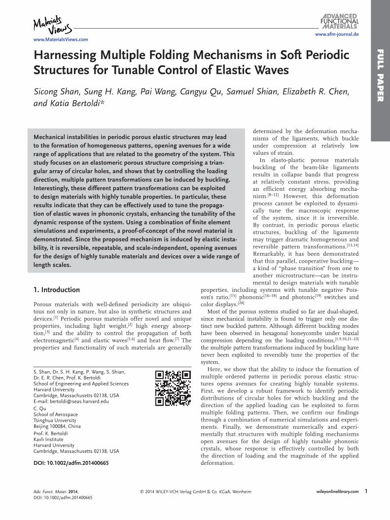
To identify periodic porous elastic structures with multiple folding mechanisms, we start by investigating the fl exibility of periodic planar networks built from rigid corner-connected polygons, which can rotate freely. While a network of connected squares has a single folding mechanism (see Supporting Infor-mation), it has been recently shown that in planar networks built from equilateral triangles the number of folding mechanisms grows with the size of unit cell. [ 24 ] Here, we focus on the simplest of such tilings made of triangles – the kagome lattice. In this rigid network, the triangles are corner-connected to form hex-agonal holes in the undeformed confi guration and the smallest unit cell consists of only two triangles (see Figure 1 -top).
If we consider a single unit cell (i.e. two corner-connected triangles) as a building block, it is easy to see that the periodic network has only one folding mechanism, in which all hexag-onal holes progressively reduce to 3-point star-like shapes (see Figure 1 a and Supporting Information). However, if we focus on a representative volume element (RVE) comprising an array of 1 × 2 unit cells (i.e. four corner-connected triangles) another folding mechanism emerges, resulting in a pattern of sheared voids where the shear direction alternates back and forth from row to row (see Figure 1 b and Supporting Information). Finally, for a RVE consisting of 8 triangles, three other mechanisms are found: one consisting of alternating rows of sheared and 3-point star-like voids (see Figure 1 c); another characterized by alter-nating rows of elongated holes oriented in horizontal and vertical direction and at ±30° with respect to the vertical direction (see Figure 1 d); and a chiral pattern comprising six highly deformed voids surrounding an undeformed one (see Figure 1 e).
Additional folding mechanisms can then be identifi ed by considering larger RVEs (see Supporting Information). How-ever, all these mechanisms share the same basic elements found in the patterns shown in Figure 1 . We also note that in all the identifi ed folding mechanisms the triangles are found either to rotate by ±α (i.e. by the same amount either in clock-wise or anti-clockwise direction, see magenta and cyan trian-gles in Figure 1 ) or not to rotate at all (i.e. α = 0, see yellow triangles in Figure 1 ), facilitating the construction of folding mechanisms for large RVEs.
Finally, given the fi nite size of the elastomeric samples con-sidered in this study, it is worth pointing out that we expect only the basic folding mechanisms shown in Figure 1 to be triggered during loading.
2.2. From Networks of Rigid Polygons to Continuum Porous Structures
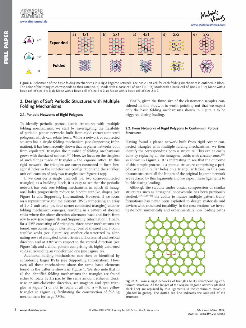
Having found a planar network built from rigid corner con-nected triangles with multiple folding mechanisms, we then identify the corresponding porous structure. This can be easily done by replacing all the hexagonal voids with circular ones, [ 25 ] as shown in Figure 2 . It is interesting to see that the outcome of this simple process is a porous structure comprising a peri-odic array of circular holes on a triangular lattice. In this con-tinuum structure all the hinges of the original kagome network are replaced by thin ligaments and we expect these ligaments to buckle during loading.
Although the stability under biaxial compression of similar structures such as hexagonal honeycombs has been previously studied, [ 1,9,10,21–23 ] the ability to induce multiple pattern trans-formations has never been exploited to design materials and devices with enhanced tunability. In the next sections we inves-tigate both numerically and experimentally how loading paths
Adv. Funct. Mater. 2014, DOI: 10.1002/adfm.201400665
Figure 1. Schematic of the basic folding mechanisms in a rigid kagome network. The basic unit cell for each folding mechanism is outlined in black. The color of the triangles corresponds to their rotation. a) Mode with a basic cell of size 1 × 1; b) Mode with a basic cell of size 2 × 1; c) Mode with a basic cell of size 4 × 1; d) Mode with a basic cell of size 2 × 2; e) Mode with a basic cell of size 2 × 2.
Figure 2. From a rigid networks of triangles to its corresponding con-tinuum structure. All the hinges of the original kagome network (dashed black line) are replaced by thin ligaments in the continuum structure (shaded in green). The dotted red line indicates the unit cell of the structure.

FULL P
APER
3
www.afm-journal.dewww.MaterialsViews.com
wileyonlinelibrary.com© 2014 WILEY-VCH Verlag GmbH & Co. KGaA, Weinheim
with different angles can be exploited to trigger the different folding mechanisms shown in Figure 1 , enabling the design of materials with highly tunable responses.
3. Mechanics of Soft Periodic Structures with Multiple Folding Mechanisms
3.1. Numerical Analysis
We continue by performing fi nite element (FE) simulations to investigate the patterns induced by buckling in a triangular array of circular holes in an elastomeric matrix. We focus on a structure characterized by an initial porosity 0Ψ = 70% and assume plane strain conditions. The nonlinear fi nite-element code ABAQUS/STANDARD is used to deform the structures as well as to investigate its stability. For all the analyses, 2D fi nite element models are constructed using triangular quad-ratic elements (element type CPE6H in ABAQUS) and the accuracy of the mesh is ascertained through a mesh refi nement study. Moreover, the response of the silicone rubber used in the experiments to cast the samples is captured using the incom-pressible Neo-Hookean hyperelastic model [ 26 ] with initial shear modulus 0μ .
Since the fi nite-sized specimens are necessarily infl uenced by boundary conditions at the edges, we focus on the response of the corresponding infi nite periodic structure and study the response of rectangular RVEs by applying periodic boundary conditions. [ 27,28 ] We investigate the response of the porous structure under biaxial loading so that the macroscopic defor-mation gradient F is given by
(1 ) (1 ) ,xx yyFF ee ee ee ee ee eexx xx yy zz zzyyε ε= + ⊗ + + ⊗ + ⊗ (1)
where εxx and ε yy denote the macroscopically applied nominal strains and eexx , eeyy and eezz are the basis vectors of Cartesian coordinates.
Without loss of generality, we focus our attention to propor-tional straining paths in principal nominal strain space. More specifi cally, we assume that the ratio of the principal nominal strains is fi xed, namely:
cos( ), sin( )ε λ θ ε λ θ= =xx yy (2)
where λ is the monotonically increasing load parameter and θ is the load path angle. In this study we consider 3 /2π θ π≤ ≤ to investigate various biaxial compression loading conditions. To facilitate the comparison between deformed confi gurations obtained for different values of θ , we also introduce the areal strain defi ned as [ 29 ]
(1 )(1 ) 1
( ( ) ( )) ( ) ( )
0
02
ε ε ε
λ θ θ λ θ θ
= − = + + −
= + +
A A
Acos sin cos sin
Area xx yy
(3)
0A and A denote the area of the RVE in the undeformed and deformed confi guration, respectively.
To understand the patterns emerging as the result of buck-ling in the structure, we start by investigating the stability of
the system. Taking the rectangular domain highlighted by red box in Figure 2 as unit cell, we consider RVEs consisting of m × n cells subjected to periodic boundary conditions. For a given value of θ we progressively load each RVE and calculate its natural frequency along the loading path, accounting for the effect of large deformation induced by loading. As an example, in Figure 3 a we show the results of the stability analysis for an RVE comprising 2 × 2 unit cells and loading path angle θ π= . In the undeformed confi guration (i.e. λ = 0) all eigenvalues
2ω are positive. However, as λ increases, the eigenvalues associated with each mode gradually decrease and eventually become negative. The critical loading parameter λcr associated with each mode can be easily extracted from the data, since it corresponds to the intersection point between each curve and the horizontal line 02ω = .
For this specifi c case, we fi nd that the lowest critical loading parameter 0.0331,1λ =cr is associated with a mode that resem-bles the folding mechanism shown in Figure 1 d for the kagome network. Here and in the following we refer to this mode as to the X-mode. The second mode is then triggered at
0.0357,2λ =cr , resulting in a pattern similar to that reported in Figure 1 b, which we denote as Z-mode. Subsequently, the third and fourth modes are found at 0.0476,3 ,4λ λ= =cr cr consisting of alternating rows of sheared and 3-point star-like voids as that shown in Figure 1 c. Finally the fi fth mode is triggered at
0.0665,5λ =cr , comprising an array of 3-point star-like voids as that reported in Figure 1 a.
Identical calculations are then repeated for RVEs of different sizes and the critical strain of the infi nite periodic structure for the given load path angle θ is then defi ned as the minimum of λcr on all possible periodic RVEs. In Figure 3 b we report the critical strains for periodic RVEs with m × n cells for θ π= . The results indicate that the critical loading parameter is the minimum for RVEs comprising an even number of unit cells in both directions and it is associated with the X-mode. Higher λcr is found for RVEs with an odd number of unit cells either in vertical or horizontal direction, for which the Z-mode is found to be critical. Therefore, when the structure is compressed with loading path angle θ π= , we expect the X-mode to be triggered during loading.
Finally, to construct the instability surface we repeat the same calculations for different loading path angles θ . We fi rst note that for all considered values of θ , the X- and Z-mode are always triggered either as fi rst or second mode. In Figure 3 c we then plot the critical load parameter associated with the X- and Z-mode as a function of θ . The critical load parameter λcr associated with the X-mode is found to decrease at fi rst, to reach a minimum at (5/ 4 1/36)θ π= − and then to pro-gressively increase. Similar behavior is found for the critical loading parameter associated to the Z-mode, but in this case the minimum occurs at (5/4 1/36)θ π= + . Interestingly, for
5 /4θ π< the critical loading parameter λcr associated to the X-mode is always lower than that corresponding to the Z-mode, so that the X-mode is expected to emerge during deformation for this range of loading path angles. By contrast, the Z-mode is expected to be triggered when 5 /4 3 /2π θ π< < , since in this case the lowest critical loading parameter is that corresponding to the Z-mode. Finally, it is worth noting that both the X- and Z-mode are characterized by the same critical loading para-meter for 5 /4θ π= , suggesting that for this specifi c loading
Adv. Funct. Mater. 2014, DOI: 10.1002/adfm.201400665

FULL
PAPER
4
www.afm-journal.dewww.MaterialsViews.com
wileyonlinelibrary.com © 2014 WILEY-VCH Verlag GmbH & Co. KGaA, Weinheim
direction a pattern corresponding to a linear combination of both modes may be triggered.
Next, guided by the stability analysis we conduct a post buck-ling analysis on a RVE consisting of 2 × 2 unit cells by applying
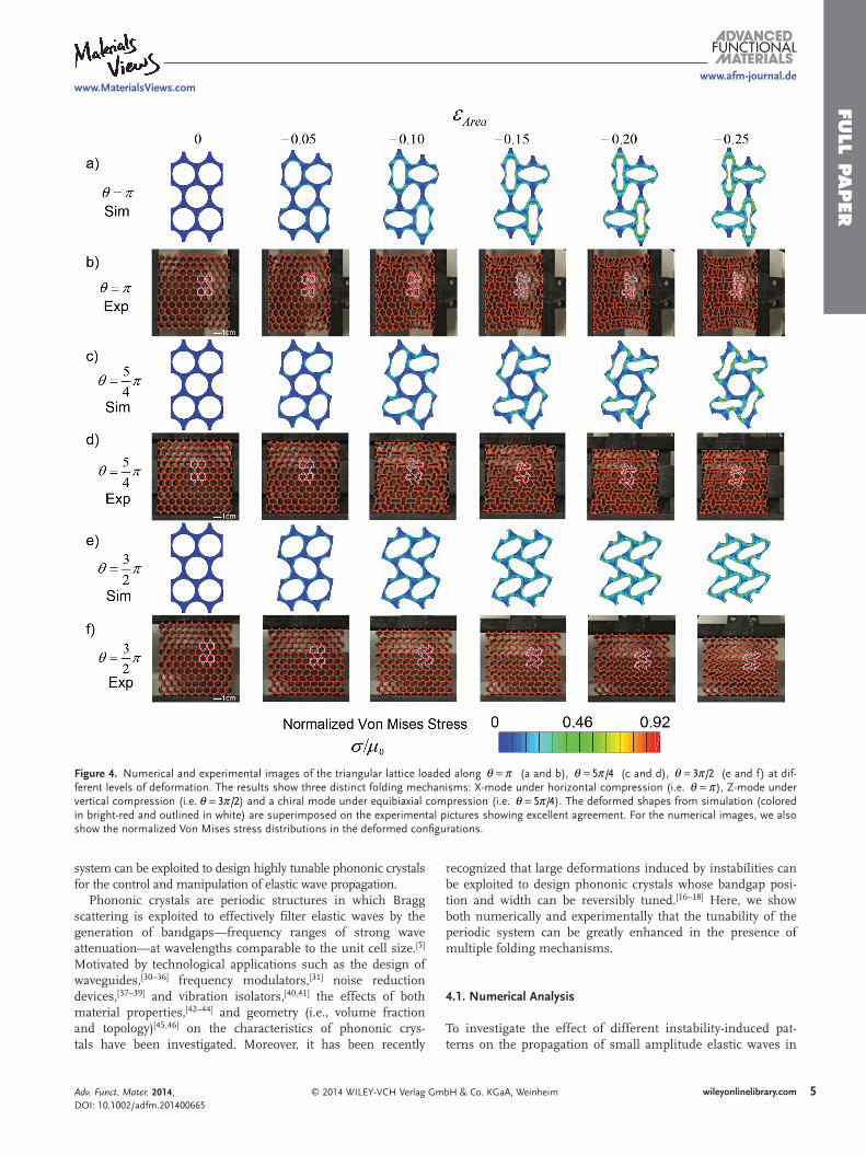
periodic boundary conditions and introducing a geometrical imperfection with the form of the fi rst two eigenmodes. In Figure 4 a, c and e we report numerical predictions of the pat-tern evolution for θ π= , 5 /4π and 3 /2π at different values of areal strain εArea . Initially, the circular holes deform gradually and homogeneously. However, a transformation to a strikingly different pattern is triggered very early along the loading path (see images at 0.05ε = −Area ) and the new patterns become fur-ther accentuated in shape with increasing strain as seen in the images at 0.10ε = −Area , 0.15− , 0.20− and 0.25− . As predicted by the stability analysis, the structure deforms into the X- and Z-mode when θ π= and 3 /2π , respectively.
However, a new chiral pattern resembling that reported in Figure 1 e for the kagome network emerges when the structure is compressed equibiaxially (i.e. 5 /4θ π= ). Interestingly, this chiral pattern does not correspond to one of the modes predicted by the stability analysis, but it can be obtained as a linear combi-nation of the X- and Z-mode (see Supporting Information).
3.2. Experiments
To verify our numerical analysis, we fabricate centimeter scale elastomeric structures comprising 10 × 12 unit cells and char-acterized by initial porosity 0Ψ = 70%, hole diameter 0D = 8 mm and out-of-plane thickness ∼50 mm. The samples for the experiments are fabricated using silicone rubber (Mold Max 60 from Smooth-On Inc, Young’s modulus E = 2.16 MPa) and a mold-casting process with molds prepared by 3D rapid proto-typing. In-plane biaxial compression tests are performed using a custom-built testing set-up with four linear stages (see Sup-porting Information).
Representative pictures taken during the tests at different levels of εArea are presented in Figure 4 b, d and f for θ π= , 5 /4π and 3 /2π , respectively. We start by noting that there is excellent agreement between numerical (Figure 4 a, c and e) and experimental (Figure 4 b, d and f) results. In particular, the effect of the boundary conditions is found to be negligible and the pattern transformations induced by instability are remark-ably uniform across the samples, so that the behavior of the fi nite size sample does not deviate from that of the infi nite peri-odic structure investigated numerically. Note that for the tests performed with θ π= and 3 /2θ π= , we do not constrain the deformation in lateral direction, since we fi nd the lateral strain to be negligible (more specifi cally, we fi nd the absolute value of lateral strain to be less than 0.05). Finally, since the speci-mens are made of an elastomeric material, the process is fully reversible and repeatable. Upon release of the applied loading condition, the deformed samples recover their original confi gu-rations, suggesting that this deformation mechanism can be exploited for the design of materials with tunable properties.
4. Harnessing Multiple Folding Mechanisms to Design Tunable Phononic Crystals
Having demonstrated that multiple folding mechanism can be easily triggered in a triangular array of circular voids by simply changing the loading path angle θ , in this section we show that the
Adv. Funct. Mater. 2014, DOI: 10.1002/adfm.201400665
Figure 3. Numerical study of the instability of a periodic structure with multiple folding mechanisms. a) Evolution of eigenvalues at different levels of compression (loading along θ π= path) and corresponding deforma-tion modes. The intersection points of each curve with the horizontal line ω = 02 corresponds to the critical loading parameter λcr for each mode. b) Critical loading parameter λcr for RVEs consisting of m × n unit cells (loading along θ π= path), where a unit cell consists of a rectangular domain with two voids. The results indicate that confi gurations with even number of unit cells along the two directions have the minimum critical strain. c) Critical loading parameter λcr associated to the X-mode (blue line) and Z-mode (green line) as a function of the loading path angle θ .
FULL P
APER
5
www.afm-journal.dewww.MaterialsViews.com
wileyonlinelibrary.com© 2014 WILEY-VCH Verlag GmbH & Co. KGaA, Weinheim
system can be exploited to design highly tunable phononic crystals for the control and manipulation of elastic wave propagation.
Phononic crystals are periodic structures in which Bragg scattering is exploited to effectively fi lter elastic waves by the generation of bandgaps—frequency ranges of strong wave attenuation—at wavelengths comparable to the unit cell size. [ 5 ] Motivated by technological applications such as the design of waveguides, [ 30–36 ] frequency modulators, [ 31 ] noise reduction devices, [ 37–39 ] and vibration isolators, [ 40,41 ] the effects of both material properties, [ 42–44 ] and geometry (i.e., volume fraction and topology) [ 45,46 ] on the characteristics of phononic crys-tals have been investigated. Moreover, it has been recently
recognized that large deformations induced by instabilities can be exploited to design phononic crystals whose bandgap posi-tion and width can be reversibly tuned. [ 16–18 ] Here, we show both numerically and experimentally that the tunability of the periodic system can be greatly enhanced in the presence of multiple folding mechanisms.
4.1. Numerical Analysis
To investigate the effect of different instability-induced pat-terns on the propagation of small amplitude elastic waves in
Adv. Funct. Mater. 2014, DOI: 10.1002/adfm.201400665
Figure 4. Numerical and experimental images of the triangular lattice loaded along θ π= (a and b), θ π= 5 /4 (c and d), θ π= 3 /2 (e and f) at dif-ferent levels of deformation. The results show three distinct folding mechanisms: X-mode under horizontal compression (i.e. θ π= ), Z-mode under vertical compression (i.e. θ π= 3 /2) and a chiral mode under equibiaxial compression (i.e. θ π= 5 /4). The deformed shapes from simulation (colored in bright-red and outlined in white) are superimposed on the experimental pictures showing excellent agreement. For the numerical images, we also show the normalized Von Mises stress distributions in the deformed confi gurations.
FULL
PAPER
6
www.afm-journal.dewww.MaterialsViews.com
wileyonlinelibrary.com © 2014 WILEY-VCH Verlag GmbH & Co. KGaA, Weinheim
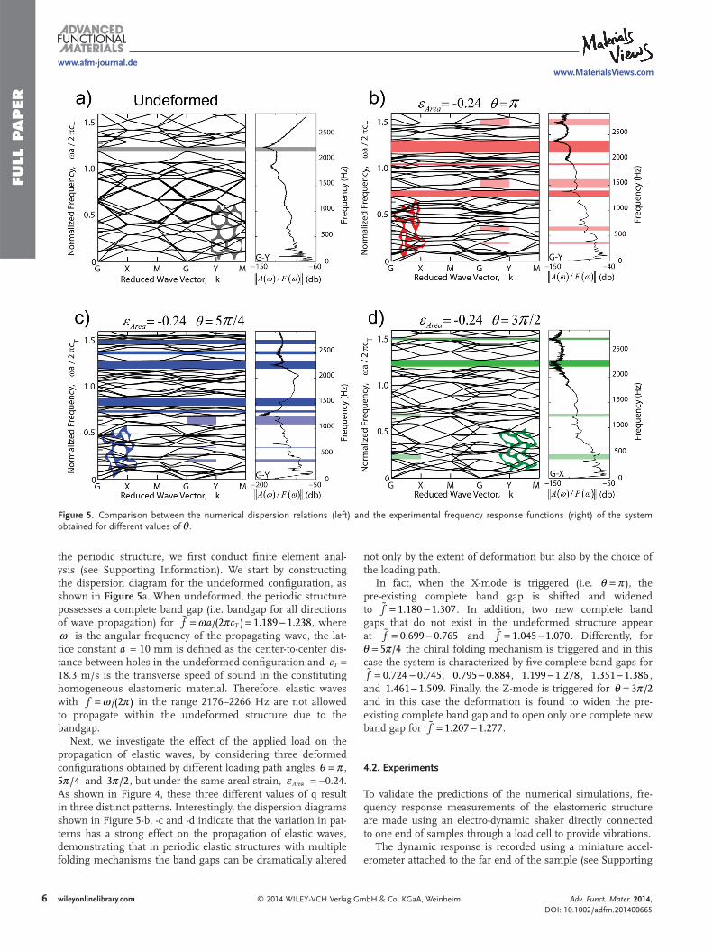
the periodic structure, we fi rst conduct fi nite element anal-ysis (see Supporting Information). We start by constructing the dispersion diagram for the undeformed confi guration, as shown in Figure 5 a. When undeformed, the periodic structure possesses a complete band gap (i.e. bandgap for all directions of wave propagation) for /(2 ) 1.189 1.238� ω π= = −f a cT , where ω is the angular frequency of the propagating wave, the lat-tice constant a = 10 mm is defi ned as the center-to-center dis-tance between holes in the undeformed confi guration and cT = 18.3 m/s is the transverse speed of sound in the constituting homogeneous elastomeric material. Therefore, elastic waves with /(2 )ω π=f in the range 2176–2266 Hz are not allowed to propagate within the undeformed structure due to the bandgap.
Next, we investigate the effect of the applied load on the propagation of elastic waves, by considering three deformed confi gurations obtained by different loading path angles θ π= , 5 /4π and 3 /2π , but under the same areal strain, εArea = −0.24. As shown in Figure 4 , these three different values of q result in three distinct patterns. Interestingly, the dispersion diagrams shown in Figure 5 -b, -c and -d indicate that the variation in pat-terns has a strong effect on the propagation of elastic waves, demonstrating that in periodic elastic structures with multiple folding mechanisms the band gaps can be dramatically altered
not only by the extent of deformation but also by the choice of the loading path.
In fact, when the X-mode is triggered (i.e. θ π= ), the pre-existing complete band gap is shifted and widened to 1.180 1.307� = −f . In addition, two new complete band gaps that do not exist in the undeformed structure appear at 0.699 0.765� = −f and 1.045 1.070� = −f . Differently, for
5 /4θ π= the chiral folding mechanism is triggered and in this case the system is characterized by fi ve complete band gaps for
0.724 0.745� = −f , 0.795 0.884− , 1.199 1.278− , 1.351 1.386− , and 1.461 1.509− . Finally, the Z-mode is triggered for 3 /2θ π= and in this case the deformation is found to widen the pre-existing complete band gap and to open only one complete new band gap for 1.207 1.277� = −f .
4.2. Experiments
To validate the predictions of the numerical simulations, fre-quency response measurements of the elastomeric structure are made using an electro-dynamic shaker directly connected to one end of samples through a load cell to provide vibrations.
The dynamic response is recorded using a miniature accel-erometer attached to the far end of the sample (see Supporting
Adv. Funct. Mater. 2014, DOI: 10.1002/adfm.201400665
Figure 5. Comparison between the numerical dispersion relations (left) and the experimental frequency response functions (right) of the system obtained for different values of θ .
FULL P
APER
7
www.afm-journal.dewww.MaterialsViews.com
wileyonlinelibrary.com© 2014 WILEY-VCH Verlag GmbH & Co. KGaA, WeinheimAdv. Funct. Mater. 2014, DOI: 10.1002/adfm.201400665
Information). Measurements are conducted at different level of deformation and the transmittance is computed as the ratio between the output acceleration signal recorded at the far end of the sample and the input force signal from the load cell (i.e.,
( )/ ( )ω ωA F ). Figure 5 shows the comparison between numerical and
experimental results. For each of the four panels in Figure 5 , the dispersion plots on the left are calculated numerically and plots on the right show the transmittance curves from experi-ments. Here, the numerical calculations consider all propa-gation directions in an infi nitely periodic structure, while the experimental results are shown for only one propagation direc-tion (G-Y direction for Figure 5 a, b and c; G-X direction for d). Nevertheless, we still observe a good match between these two sets of results. In the undeformed case, the experimental response indicates an apparent attenuation at the numerically calculated band gap frequency. After the structure is deformed into different patterns, the calculated complete band gaps can still fi nd their signatures in the experimental results, with very few exceptions due to fi nite-size boundary effects that are not investigated in this study. Furthermore, the transmittance curves from experiments also exhibit some features of direc-tional band gaps, indicated by the lighter color-shaded areas in Figure 5 .
5. Conclusion
We demonstrated both numerically and experimentally the design of highly tunable phononic crystals by harnessing multiple folding mechanisms in periodic elastomeric struc-tures comprising a triangular array of circular holes. We started with a geometrical analysis of 2D rigid periodic net-works and found that a kagome lattice can have multiple folding mechanisms.
Guided by these results, we rationally designed the corre-sponding continuum soft periodic porous structure and showed that three different patterns induced by buckling can be trig-gered during compressive loading by changing the direction of loading. Remarkably, the dynamic response of the system was found to be highly affected by the pattern induced by buckling, demonstrating that the band gaps can be tuned both by defor-mation mode and the extent of deformation.
Our fi nding opens new opportunities to design multi-functional devices with enhanced tunability because (i) the mechanism can be applied to various length-scales; (ii) the various patterns can be triggered upon application of dif-ferent stimuli and using different materials; (iii) the process is fully reversible and (iv) more importantly, the formation of different patterns can be easily controlled by changing the loading direction. By engineering geometry, length scales, and materials, we can envision smart systems that control the wave propagation autonomously depending on the loading conditions.
6. Experimental Section Please see the Supporting Information for experimental details.
Supporting Information Supporting Information is available from the Wiley Online Library or from the author.
Acknowledgements This work has been supported by NSF through grant DMR-0820484 (Harvard MRSEC) and grant CMMI-1149456 (CAREER) and by the Wyss Institute through the Seed Grant Program. K.B. acknowledges start-up funds from the Harvard School of Engineering and Applied Sciences and the support of the Kavli Institute at Harvard University. E.R.C. acknowledges NSF MSPRF grant DMS-1204686. The authors wish to thanks Prof. David Clarke for the help with the experiments and Dr. Fillippo Casadei for useful discussions.
Received: February 26, 2014 Published online:
[1] L. Gibson , M. Ashby , Cellular Solids: Structure and Properties , Cam-bridge University Press , Cambridge 1999 .
[2] T. Schaedler , A. Jacobsen , A. Torrents , A. Sorensen , J. Lian , J. Greer , L. Valdevit , W. Carter , Science 2011 , 334 , 962 – 965 .
[3] J.-H. Lee , L. Wang , M. C. Boyce , E. L. Thomas , Nano Lett. 2012 , 12 , 4392 – 4396 .
[4] D. Schurig , J. J. Mock , B. J. Justice , S. A. Cummer , J. B. Pendry , A. F. Starr , D. R. Smith , Science 2006 , 314 , 977 – 980 .
[5] M. S. Kushwaha , P. Halevi , L. Dobrzynski , B. Djafari-Rouhani , Phys. Rev. Lett. 1993 , 71 , 2022 – 2025 .
[6] M. Maldovan , E. L. Thomas , Periodic Materials and Interference lithography for Photonics, Phononics and Mechanics , Wiley-VCH , Weinheim 2009 .
[7] M. Maldovan , Phys. Rev. Lett. 2013 , 110 , 025902 . [8] T. Wierzbicki , W. Abramowicz , J. Appl. Mech. 1983 , 50 , 727 – 734 . [9] S. Papka , S. Kyriakides , Int. J. Solids Struct. 1999 , 36 , 4367 – 4396 .
[10] S. Papka , S. Kyriakides , Int. J. Solids Struct. 1999 , 36 , 4397 – 4423 . [11] E. Wu , W. Jiang , Int. J. Impact Eng. 1997 , 19 , 439 – 456 . [12] A. M. Hayes , A. Wang , B. M. Dempsey , D. L. McDowell , Mech.
Mater. 2004 , 36 , 691 – 713 . [13] T. Mullin , S. Deschanel , K. Bertoldi , M. C. Boyce , Phys. Rev. Lett.
2007 , 99 , 084301 . [14] Y. Zhang , E. A. Matsumoto , A. Peter , P. Lin , R. D. Kamien , S. Yang ,
Nano Lett. 2008 , 8 , 1192 – 1196 . [15] K. Bertoldi , P. Reis , S. Willshaw , T. Mullin , Adv. Mater. 2010 , 22 ,
361 – 366 . [16] K. Bertoldi , M. C. Boyce , Phys. Rev. B 2008 , 77 , 052105 . [17] J. Jang , C. Y. Koh , K. Bertoldi , M. C. Boyce , E. L. Thomas , Nano Lett.
2009 , 9 , 2113 – 2119 . [18] P. Wang , J. Shim , K. Bertoldi , Phys. Rev. B 2013 , 88 , 014304 . [19] D. Krishnan , H. Johnson , J. Mech. Phys. Solids 2009 , 57 , 1500 – 1513 . [20] J. Li , J. Shim , J. Deng , J. T. B. Overvelde , X. Zhu , K. Bertoldi , S. Yang ,
Soft Matter 2012 , 8 , 10322 – 10328 . [21] L. Gibson , M. Ashby , J. Zhang , T. Triantafi llou , Int. J. Solids Struct.
1989 , 31 , 635 – 663 . [22] J. Chung , A. Waas , J. Eng. Mech. 2001 , 127 , 180 – 193 . [23] N. Ohno , D. Okumura , H. Noguchi , J. Mech. Phys. Solids 2002 , 50 ,
1125 – 1153 . [24] V. Kapko , M. Treacy , M. Thorpe , S. Guest , Proc. R. Soc. A 2009 , 465 ,
3517 – 3530 . [25] J. Shim , S. Shan , A. Kosmrlj , S. H. Kang , E. R. Chen , J. C. Weaver ,
K. Bertoldi , Soft Matter 2013 , 9 , 8198 – 8202 . [26] R. W. Ogden , Nonlinear Elastic Deformations , Dover , New York 1998 .

FULL
PAPER
8
www.afm-journal.dewww.MaterialsViews.com
wileyonlinelibrary.com © 2014 WILEY-VCH Verlag GmbH & Co. KGaA, Weinheim Adv. Funct. Mater. 2014, DOI: 10.1002/adfm.201400665
[27] M. Danielsson , D. Parks , M. Boyce , J. Mech. Phys. Solids 2002 , 50 , 351 – 379 .
[28] K. Bertoldi , M. C. Boyce , S. Deschanel , S. M. Prange , T. Mullin , J. Mech. Phys. Solids 2008 , 56 , 2642 – 2668 .
[29] D. Needham , R. Nunn , Biophys. J. 1990 , 58 , 997 – 1009 . [30] A. Khelif , A. Choujaa , S. Benchabane , B. Djafari-Rouhani , V. Laude ,
Appl. Phys. Lett. 2004 , 84 , 4400 – 4402 . [31] M. Kafesaki , M. M. Sigalas , N. Garcia , Phys. Rev. Lett. 2000 , 85 ,
4044 – 4047 . [32] A. Khelif , B. Djafari-Rouhani , J. O. Vasseur , P. A. Deymier ,
P. Lambin , L. Dobrzynski , Phys. Rev. B 2002 , 65 , 174308 . [33] J.-H. Sun , T.-T. Wu , Phys. Rev. B 2005 , 71 , 174303 . [34] J.-H. Sun , T.-T. Wu , IEEE Ultrasonics Symposium 2006 , 1 , 673 . [35] J.-H. Sun , T.-T. Wu , Phys. Rev. B 2007 , 76 , 104304 . [36] J. O. Vasseur , A. Hennion , B. Rouhani , F. Duval , B. Dubus ,
Y. Pennec , J. App. Phys. 2007 , 101 , 114904 . [37] D. Elser , U. L. Andersen , A. Korn , O. Glöckl , S. Lorenz ,
C. Marquardt , G. Leuchs , Phys. Rev. Lett. 2006 , 97 , 133901 .
[38] T. Elnady , A. Elsabbagh , W. Akl , O. Mohamady , V. M. Garcia-Chocano , D. Torrent , F. Cervera , J. Snchez-Dehesa , Appl. Phys. Lett. 2009 , 94 , 134104 .
[39] F. Casadei , L. Dozio , M. Ruzzene , K. Cunefare , J. Sound. Vib. 2010 , 329 , 3632 .
[40] Y. Dian-Long , L. Yao-Zong , Q. Jing , Z. Hong-Gang , L. Zhi-Ming , Chin. Phys. Lett. 2005 , 22 , 1958 .
[41] F. Casadei , B. Beck , K. A. Cunefare , M. Ruzzene , Int. J. Solids Struct. 2012 , 23 , 1169 .
[42] D. Bria , B. Djafari-Rouhani , Phys. Rev. E 2002 , 66 , 056609 . [43] J. O. Vasseur , B. Djafari-Rouhani , L. Dobrzynski , M. S. Kushwaha ,
P. Halevi , J. Phys. Condesed Mat. 1994 , 6 , 8759 . [44] X.-Z. Zhou , Y.-S. Wang , C. Zhang , J. App. Phys. 2009 , 106 ,
014903 . [45] J.-B. Li , Y.-S. Wang , C. Zhang , J. Vib. Acoust. 2013 , 135 ,
031015 . [46] A. Movchan , N. Movchan , S. Haq , Mat. Sci. Eng. 2006 , 431 ,
175183 .

Copyright WILEY-VCH Verlag GmbH & Co. KGaA, 69469 Weinheim, Germany, 2014.
Supporting Information
for Adv. Funct. Mater., DOI: 10.1002/adfm.201400665
Harnessing Multiple Folding Mechanisms in Soft PeriodicStructures for Tunable Control of Elastic Waves
Sicong Shan, Sung H. Kang, Pai Wang, Cangyu Qu, SamuelShian, Elizabeth R. Chen, and Katia Bertoldi*
Supporting Information forHarnessing multiple folding mechanisms in soft periodic structures for tunable
control of elastic waves
Sicong Shan,1 Sung H. Kang,1 Pai Wang,1 Cangyu Qu,2 Samuel Shian,1 Elizabeth R. Chen,1 and Katia Bertoldi1, 3
1School of Engineering and Applied Sciences, Harvard University, Cambridge, Massachusetts 02138, USA2School of Aerospace, Tsinghua University, Beijing, China, 100084
3Kavli Institute, Harvard University, Cambridge, Massachusetts 02138, USA
PERIODIC NETWORKS OF RIGID POLYGONS
To identify periodic porous elastic structures with multiple folding mechanisms, we investigate the flexibility ofperiodic planar networks built from rigid corner-connected (hinged) polygons, which can rotate freely around thehinges. First, we show that a network of connected squares has a single folding mechanism. Then, as previouslydemonstrated by Guest et al. [1], we show that in planar networks built from equilateral triangles the number offolding mechanisms grows with the size of unit cell.
Network of rigid squares
We start by investigating the folding mechanisms of a network of connected squares. To demonstrate that thisstructure has a single folding mechanism, we consider unit cells of different sizes and determine their folding mech-anisms by enforcing geometric compatibility. We first focus on a unit cell consisting of two connected squares andshow that in this case no folding mechanism is supported by the network. Then, we consider a unit cell comprisingfour squares and show that in this case only one folding mechanism exists. Our simple analysis can be extended tolarger unit cells, indicating that only one single folding mechanism is possible for this network (for the sake of brevityhere we do not report results for unit cells with more than four squares).
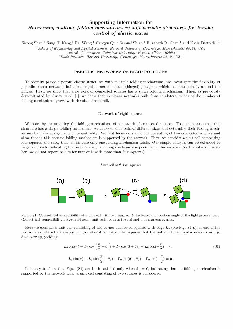
Unit cell with two squares
Figure S1: Geometrical compatibility of a unit cell with two squares. θ1 indicates the rotation angle of the light-green square.Geometrical compatibility between adjacent unit cells requires the red and blue markers overlap.
Here we consider a unit cell consisting of two corner-connected squares with edge L0 (see Fig. S1-a). If one of thetwo squares rotate by an angle θ1, geometrical compatibility requires that the red and blue circular markers in Fig.S1-c overlap, yielding
L0 cos(π) + L0 cos(π
2+ θ1
)+ L0 cos(0 + θ1) + L0 cos(−π
2) = 0, (S1)
L0 sin(π) + L0 sin(π
2+ θ1) + L0 sin(0 + θ1) + L0 sin(−π
2) = 0.
It is easy to show that Eqs. (S1) are both satisfied only when θ1 = 0, indicating that no folding mechanism issupported by the network when a unit cell consisting of two squares is considered.
2
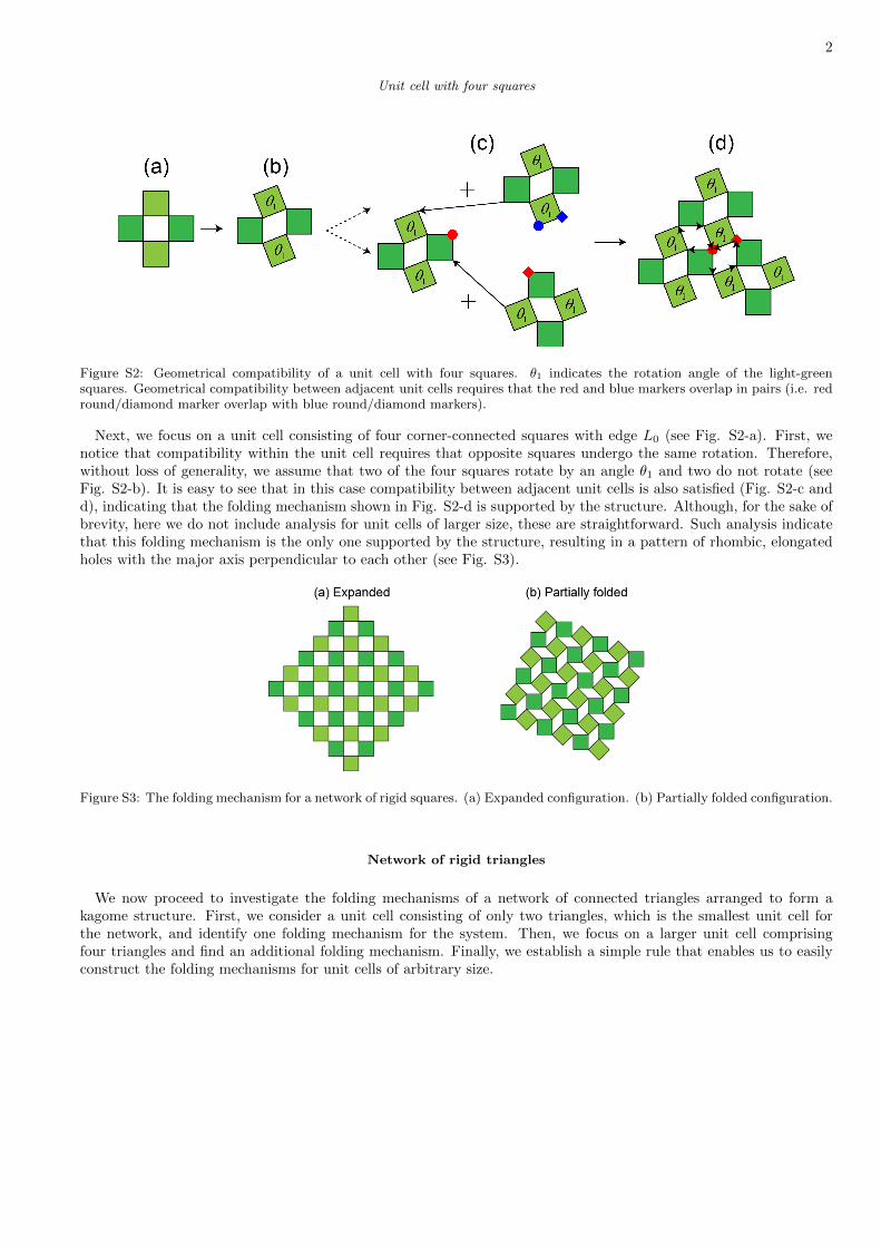
Unit cell with four squares
Figure S2: Geometrical compatibility of a unit cell with four squares. θ1 indicates the rotation angle of the light-greensquares. Geometrical compatibility between adjacent unit cells requires that the red and blue markers overlap in pairs (i.e. redround/diamond marker overlap with blue round/diamond markers).
Next, we focus on a unit cell consisting of four corner-connected squares with edge L0 (see Fig. S2-a). First, wenotice that compatibility within the unit cell requires that opposite squares undergo the same rotation. Therefore,without loss of generality, we assume that two of the four squares rotate by an angle θ1 and two do not rotate (seeFig. S2-b). It is easy to see that in this case compatibility between adjacent unit cells is also satisfied (Fig. S2-c andd), indicating that the folding mechanism shown in Fig. S2-d is supported by the structure. Although, for the sake ofbrevity, here we do not include analysis for unit cells of larger size, these are straightforward. Such analysis indicatethat this folding mechanism is the only one supported by the structure, resulting in a pattern of rhombic, elongatedholes with the major axis perpendicular to each other (see Fig. S3).
Figure S3: The folding mechanism for a network of rigid squares. (a) Expanded configuration. (b) Partially folded configuration.
Network of rigid triangles
We now proceed to investigate the folding mechanisms of a network of connected triangles arranged to form akagome structure. First, we consider a unit cell consisting of only two triangles, which is the smallest unit cell forthe network, and identify one folding mechanism for the system. Then, we focus on a larger unit cell comprisingfour triangles and find an additional folding mechanism. Finally, we establish a simple rule that enables us to easilyconstruct the folding mechanisms for unit cells of arbitrary size.

3
Unit cell with two triangles
Figure S4: Geometrical compatibility of a unit cell with two triangles. θ1 indicates the rotation angle of the light-green triangle.Geometrical compatibility between adjacent unit cells requires the red and blue markers overlap.
Here we consider a unit cell consisting of two corner-connected triangles with edge L0 (see Fig. S4-a). If one of thetwo triangles rotates by an angle θ1 (see Fig. S4-b), geometrical compatibility requires that the red and blue circularmarkers in Fig. S4-c overlap, yielding
L0 cos(2π
3) + L0 cos(
π
3+ θ1) + L0 cos(0) + L0 cos(−π
3+ θ1) + L0 cos(−2π
3) + L0 cos(−π + θ1) = 0, (S2)
L0 sin(2π
3) + L0 sin(
π
3+ θ1) + L0 sin(0) + L0 sin(−π
3+ θ1) + L0 sin(−2π
3) + L0 sin(−π + θ1) = 0.
It is easy to see that Eqs. (S2) are automatically satisfied for any choice of 0 < θ1 < 2π/3, indicating that thefolding mechanism shown in Fig. S4-d is supported by the structure. Such folding mechanism results in the formationof a pattern where all hexagonal holes progressively reduce to 3 point star-like shapes (see Fig. S5).
Figure S5: The folding mechanism of network of rigid triangles with a unit cell with two triangles. (a) Expanded configuration.(b) Partially folded configuration.
Unit cell with four triangles
Next, we focus on a unit cell comprising of four corner-connected triangles, as shown in Fig. S6-a. Without loss ofgenerality we assume that one triangle does not rotate, while the other three triangles rotate by angles θ1, θ2 and θ3(Fig. S6-b). Geometrical compatibility between adjacent unit cells requires
L0 cos(2π
3) + L0 cos(
π
3+ θ1) + L0 cos(θ2) + L0 cos(−π
3+ θ1) + L0 cos(−2π
3) + L0 cos(−π + θ3) = 0, (S3)
L0 sin(2π
3) + L0 sin(
π
3+ θ1) + L0 sin(θ2) + L0 sin(−π
3+ θ1) + L0 sin(−2π
3) + L0 sin(−π + θ3) = 0,

4
Figure S6: Geometrical compatibility of a unit cell with four triangles. θ1, θ2, and θ3 indicates the rotation of the green,light-green and yellow triangles, respectively. Geometrical constraints between adjacent unit cells require the red and bluemarkers overlap.
which can be easily simplified to
−1 + cos(θ1) + cos(θ2)− cos(θ3) = 0, (S4)
sin(θ1) + sin(θ2)− sin(θ3) = 0.
Eqs. (S4) are automatically satisfied for {θ1 = θ3,θ2 = 0,
(S5)
and {θ1 = 0,θ2 = θ3.
(S6)
The first solution (Eqs. (S5)) results in the formation of the same pattern found when investigating the unit cellconsisting of two triangles, as shown in Fig. S5. The second solution (Eqs. (S6)) is associated to the formation of apattern of sheared voids where the shear direction alternates back and forth from row to row (see Fig. S7).
Figure S7: The additional folding mechanism of network of rigid triangles with a unit cell of four triangles. (a) Expandedconfiguration. (b) Partially folded configuration.
Folding mechanisms for larger unit cells
Additional folding mechanisms for the kagome network can be identified by repeating similar calculations as reportedabove for larger unit cells. Furthermore, the construction of additional folding mechanisms is greatly facilitated by
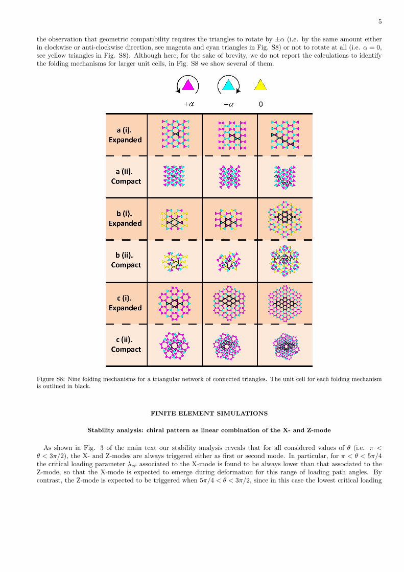
5
the observation that geometric compatibility requires the triangles to rotate by ±α (i.e. by the same amount eitherin clockwise or anti-clockwise direction, see magenta and cyan triangles in Fig. S8) or not to rotate at all (i.e. α = 0,see yellow triangles in Fig. S8). Although here, for the sake of brevity, we do not report the calculations to identifythe folding mechanisms for larger unit cells, in Fig. S8 we show several of them.
Figure S8: Nine folding mechanisms for a triangular network of connected triangles. The unit cell for each folding mechanismis outlined in black.
FINITE ELEMENT SIMULATIONS
Stability analysis: chiral pattern as linear combination of the X- and Z-mode
As shown in Fig. 3 of the main text our stability analysis reveals that for all considered values of θ (i.e. π <θ < 3π/2), the X- and Z-modes are always triggered either as first or second mode. In particular, for π < θ < 5π/4the critical loading parameter λcr associated to the X-mode is found to be always lower than that associated to theZ-mode, so that the X-mode is expected to emerge during deformation for this range of loading path angles. Bycontrast, the Z-mode is expected to be triggered when 5π/4 < θ < 3π/2, since in this case the lowest critical loading
6
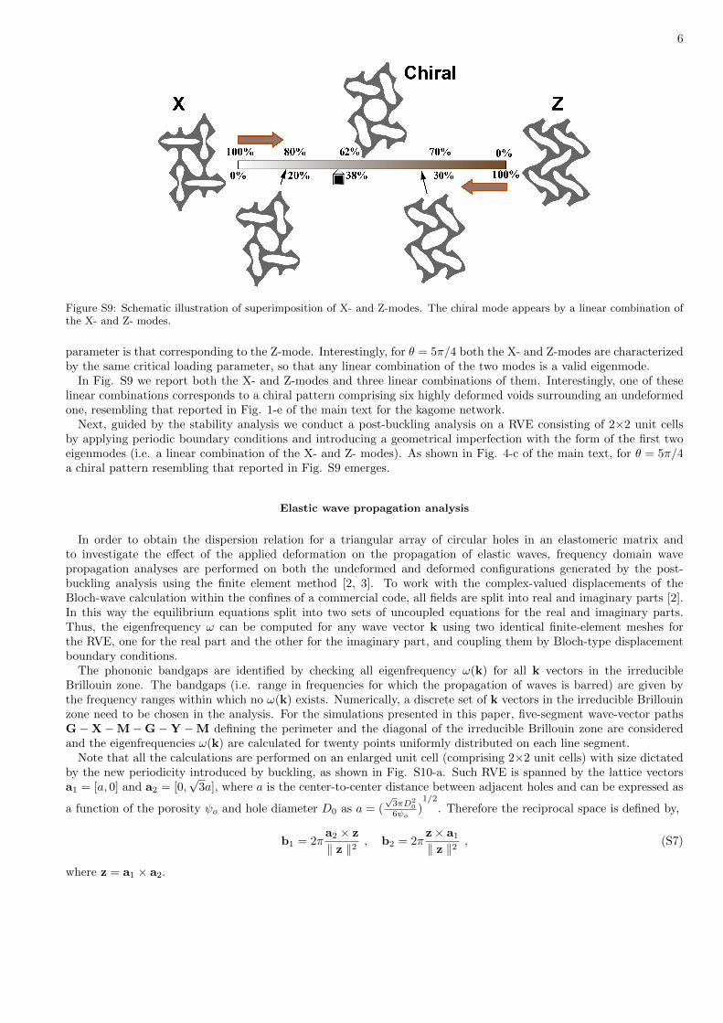
Figure S9: Schematic illustration of superimposition of X- and Z-modes. The chiral mode appears by a linear combination ofthe X- and Z- modes.
parameter is that corresponding to the Z-mode. Interestingly, for θ = 5π/4 both the X- and Z-modes are characterizedby the same critical loading parameter, so that any linear combination of the two modes is a valid eigenmode.
In Fig. S9 we report both the X- and Z-modes and three linear combinations of them. Interestingly, one of theselinear combinations corresponds to a chiral pattern comprising six highly deformed voids surrounding an undeformedone, resembling that reported in Fig. 1-e of the main text for the kagome network.
Next, guided by the stability analysis we conduct a post-buckling analysis on a RVE consisting of 2×2 unit cellsby applying periodic boundary conditions and introducing a geometrical imperfection with the form of the first twoeigenmodes (i.e. a linear combination of the X- and Z- modes). As shown in Fig. 4-c of the main text, for θ = 5π/4a chiral pattern resembling that reported in Fig. S9 emerges.
Elastic wave propagation analysis
In order to obtain the dispersion relation for a triangular array of circular holes in an elastomeric matrix andto investigate the effect of the applied deformation on the propagation of elastic waves, frequency domain wavepropagation analyses are performed on both the undeformed and deformed configurations generated by the post-buckling analysis using the finite element method [2, 3]. To work with the complex-valued displacements of theBloch-wave calculation within the confines of a commercial code, all fields are split into real and imaginary parts [2].In this way the equilibrium equations split into two sets of uncoupled equations for the real and imaginary parts.Thus, the eigenfrequency ω can be computed for any wave vector k using two identical finite-element meshes forthe RVE, one for the real part and the other for the imaginary part, and coupling them by Bloch-type displacementboundary conditions.
The phononic bandgaps are identified by checking all eigenfrequency ω(k) for all k vectors in the irreducibleBrillouin zone. The bandgaps (i.e. range in frequencies for which the propagation of waves is barred) are given bythe frequency ranges within which no ω(k) exists. Numerically, a discrete set of k vectors in the irreducible Brillouinzone need to be chosen in the analysis. For the simulations presented in this paper, five-segment wave-vector pathsG−X−M−G−Y −M defining the perimeter and the diagonal of the irreducible Brillouin zone are consideredand the eigenfrequencies ω(k) are calculated for twenty points uniformly distributed on each line segment.
Note that all the calculations are performed on an enlarged unit cell (comprising 2×2 unit cells) with size dictatedby the new periodicity introduced by buckling, as shown in Fig. S10-a. Such RVE is spanned by the lattice vectorsa1 = [a, 0] and a2 = [0,
√3a], where a is the center-to-center distance between adjacent holes and can be expressed as
a function of the porosity ψo and hole diameter D0 as a = (√3πD2
0
6ψo)1/2
. Therefore the reciprocal space is defined by,
b1 = 2πa2 × z
‖ z ‖2, b2 = 2π
z× a1‖ z ‖2
, (S7)
where z = a1 × a2.

7
Figure S10: (a) Schematic of the structure in the undeformed configuration. The considered RVE spanned by the lattice vectorsa1 and a2 is shown in grey. (b) The corresponding Brillouin zone in reciprocal space is spanned by the vectors b1 and b2.
EXPERIMENTS
Biaxial compression tests
To verify findings from numerical models that show multiple folding mechanisms depending on the loading directions,we did experiments using a custom set-up that can control the loading in two orthogonal directions independentlyproviding the capability to test the sample in arbitrary biaxial loading conditions. (see Fig. S11-a)
Biaxial compression tests were conducted on two perpendicularly placed linear quasi-static stages (model SLP-35 from Nippon Pulse America Inc.) in a displacement-controlled manner. The stages were configured to realize anoptimal spatial resolution of 1 µm. The fine movement of the stages was coordinated through a LabView program andthe ratio between the engineering strains in two directions was kept constant during the biaxial test. The specimenswere compressed through a set of customary compression fixtures, which were designed to ensure them not to collideduring the compression tests (see Fig. S11-b). The overall fixture set consisted of two pairs of parts with each pairfor the compressive movement in one of two orthogonal directions. The specimen was not clamped to the fixturesbecause the friction between the specimen and fixture surface was enough to hold the specimen. Lubricant was usedon surfaces of fixtures to reduce friction and boundary effects. The compression tests were performed at the cross-headvelocity of 5mm/min until the structure was densified. During the test, a Nikon D90 SLR camera was used to capturethe resulting patterns from the sample.
Figure S11: (a) Picture of the biaxial setup used for our compression test. (b) Sketch of the biaxial compression fixture whusedfor our compression experiments.
Wave propagation tests
To investigate the effect of different instability-induced patterns on the propagation of small amplitude elastic wavesin the periodic structure, we conducted wave propagation tests for the the udeformed sample and for three deformed
8
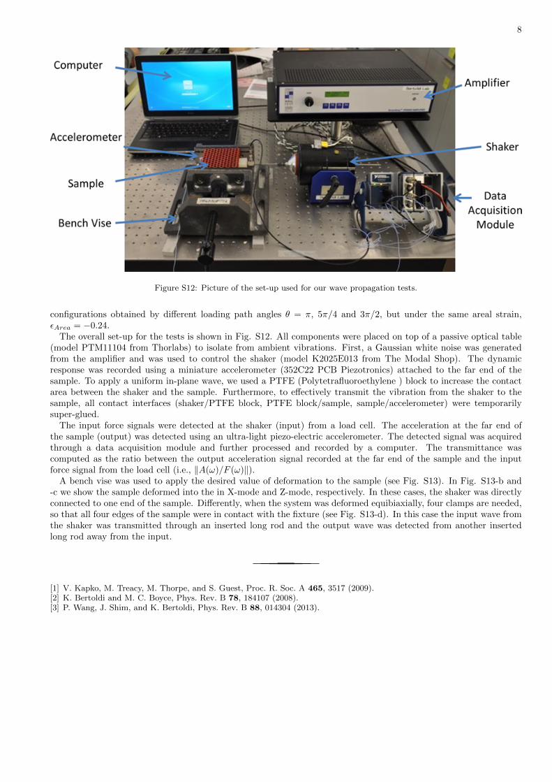
Figure S12: Picture of the set-up used for our wave propagation tests.
configurations obtained by different loading path angles θ = π, 5π/4 and 3π/2, but under the same areal strain,εArea = −0.24.
The overall set-up for the tests is shown in Fig. S12. All components were placed on top of a passive optical table(model PTM11104 from Thorlabs) to isolate from ambient vibrations. First, a Gaussian white noise was generatedfrom the amplifier and was used to control the shaker (model K2025E013 from The Modal Shop). The dynamicresponse was recorded using a miniature accelerometer (352C22 PCB Piezotronics) attached to the far end of thesample. To apply a uniform in-plane wave, we used a PTFE (Polytetrafluoroethylene ) block to increase the contactarea between the shaker and the sample. Furthermore, to effectively transmit the vibration from the shaker to thesample, all contact interfaces (shaker/PTFE block, PTFE block/sample, sample/accelerometer) were temporarilysuper-glued.
The input force signals were detected at the shaker (input) from a load cell. The acceleration at the far end ofthe sample (output) was detected using an ultra-light piezo-electric accelerometer. The detected signal was acquiredthrough a data acquisition module and further processed and recorded by a computer. The transmittance wascomputed as the ratio between the output acceleration signal recorded at the far end of the sample and the inputforce signal from the load cell (i.e., ‖A(ω)/F (ω)‖).
A bench vise was used to apply the desired value of deformation to the sample (see Fig. S13). In Fig. S13-b and-c we show the sample deformed into the in X-mode and Z-mode, respectively. In these cases, the shaker was directlyconnected to one end of the sample. Differently, when the system was deformed equibiaxially, four clamps are needed,so that all four edges of the sample were in contact with the fixture (see Fig. S13-d). In this case the input wave fromthe shaker was transmitted through an inserted long rod and the output wave was detected from another insertedlong rod away from the input.
[1] V. Kapko, M. Treacy, M. Thorpe, and S. Guest, Proc. R. Soc. A 465, 3517 (2009).[2] K. Bertoldi and M. C. Boyce, Phys. Rev. B 78, 184107 (2008).[3] P. Wang, J. Shim, and K. Bertoldi, Phys. Rev. B 88, 014304 (2013).

9
Figure S13: (a) Picture of the undeformed sample with the shaker and accelerometer connected to it. (b) Picture of the sampledeformed into the X-mode with the shaker and accelerometer connected to it. (c) Picture of the sample deformed into theZ-mode with the shaker and accelerometer connected to it. (d) Picture of the sample deformed into the chiral mode with theshaker and accelerometer connected to it.