harsh environment fiber optic connector selection - · pdf filepage 1 of 32 12/13/2011 harsh...
TRANSCRIPT

Page 1 of 32 12/13/2011
Harsh Environment Fiber Optic
Connector Selection Introduction Whether natural or manmade, cataclysmic or catastrophic, rugged and unforgiving environments call for the use of high-performance fiber optic connectors. Appropriate connector selection is essential to assure adequate optical, environmental and mechanical performance. This paper outlines and describes the attributes, environments, requirements, technologies, and potential Harsh Environment Fiber Optic (HEFO) connector selection criteria. Scope Extreme surroundings, severe conditions and misuse describe the applications requiring HEFO connectors. It is assumed that the reader has a predetermined need for using fiber optic interconnects and does not need to help in assessing the available alternatives between copper and fiber. Common connector specifications include shock, resistance to vibration, temperature, humidity, submersion, chemical resistance, crush, strength and dirt or dust. It is further assumed the reader has a cursory knowledge of fiber optic connectors and understands the principles involved in fiber optic connectivity. Available Technologies Physical contact and expanded beam are the dominant technologies used in harsh environment fiber optic connectivity. This paper briefly describes each of these two technologies but does not

Page 2 of 32 12/13/2011
discuss splicing interconnects or other alternative or exotic interconnect technologies. The paper concludes with a connector suitability trade study performed on a typical harsh environment fiber optic interconnect application. Background Robust fiber optic interconnects are needed in harsh environments. Military and aerospace systems must perform in hostile climates, inclement weather and adverse surroundings. Geophysical applications subject interconnects to demanding conditions as well. Relevant Applications/Markets Tactical, shipboard, aerospace, and geophysical applications, among others, present taxing environments for interconnects. Because fiber optic connections require alignment accuracy, these applications demand rugged, precise and proven products. Figure 1 shows several harsh environments where rugged fiber optic connectors may be utilized.
Figure 1. Typical harsh environments commonly employing rugged fiber optic interconnects

Page 3 of 32 12/13/2011
Mil/Aero Armed forces utilize fiber optics in harsh environments in myriad programs. Armies employ rugged fiber optic interconnects in tactical communications, missile systems, and radar installations. The Patriot missile system shown in Figure 2 is one highly publicized tactical weapon system using HEFO interconnects.
Figure 2. The Patriot missile system makes extensive use of fiber optics
Bandwidth, weight and electromagnetic interference considerations determine fiber optic interconnect requirements, particularly in aerospace applications. Airborne sensors require enormous bandwidth. They also need to be impervious to and not emit electromagnetic radiation. Fiber optics excel in both military and commercial airframe applications. Fiber optics in space (see Figure 3) has unique requirements, including the use of low outgassing materials, radiation exposure, and component longevity.
Figure 3. Space shuttle containing fiber optics
Page 4 of 32 12/13/2011
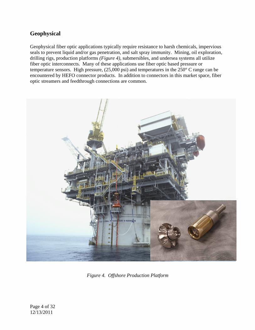
Geophysical Geophysical fiber optic applications typically require resistance to harsh chemicals, impervious seals to prevent liquid and/or gas penetration, and salt spray immunity. Mining, oil exploration, drilling rigs, production platforms (Figure 4), submersibles, and undersea systems all utilize fiber optic interconnects. Many of these applications use fiber optic based pressure or temperature sensors. High pressure, (25,000 psi) and temperatures in the 250° C range can be encountered by HEFO connector products. In addition to connectors in this market space, fiber optic streamers and feedthrough connections are common.
Figure 4. Offshore Production Platform

Page 5 of 32 12/13/2011
Oceanographic oil exploration commonly involves using streamer arrays containing fiber optic interconnects due to the inordinate quantity of captured data. Many such streamers require hybrid (electrical and fiber optic) connections containing hybrid inserts (see Figure 5).
Figure 5. Oil exploration ship with hybrid streamer interconnect Fiber optics find their way into mining operations because radio links do not work well underground. Of course, connectors in mines must be constructed with non-sparking material and be resistant to explosions. Figure 6 shows longwall shearing equipment. Figure 6. Coal mining fiber optic uses include communications, roofers and shearing equipment

Page 6 of 32 12/13/2011
Disaster Recovery/Industrial Emergency deployable communication systems (see Figure 7), nuclear power generation, broadcasting, and security applications present unique environments requiring rugged fiber optic connectors. Bandwidth, channel count, EMI, and extreme weather often determine industrial fiber optic connector requirements.
Figure 7. Deployable Telecommunications Disaster System Requirements The importance of understanding requirements cannot be understated. The ability to choose the best interconnect system and subsequent connector depends upon knowing and understanding the optical performance expectations, operating conditions, mechanical and environmental constraints, reliability requirements, and maintenance plans. System and interconnect designers must think beyond the environment in establishing and selecting components. HEFO cables and connectors are frequently subject to severe treatment and misuse. A warfighter may use cable to rappel down or climb atop a shelter. An oilfield explorer technician may pull a cable reel using the cable. Oftentimes, cables are tied to an object and placed under unintentional stress. Connectors/cables are placed in puddles, pulled dangling behind vehicles, and used haphazardly. Installation is another area fraught with potential for connector/cable damage. Accidentally, or out of necessity, fiber optic cables and connectors are astonishingly abused. Applications in contaminated environments frequently require fiber optics. Connector technology, sealing, and cleanliness all play a major role in connector selection and interconnect performance in these environments. Dust, moisture, chemical exposure, oily films, and maintenance planning must be considered for any application. Figure 8 shows a particular dusty environment common to rugged fiber optic interconnects.

Page 7 of 32 12/13/2011
Figure 8. Many HEFO applications are extraordinarily contaminated System level design dictates the type of fiber employed (typically multimode or single mode), the number of channels, and packaging density. Trade studies during system design influence cost, performance, and nearly each attribute of the interconnect system. For example, by using wavelength division multiplexing (WDM) or dense wavelength division multiplexing (DWDM) technologies, fewer actual fiber connections are required since each fiber carries multiple signals. However, while this drives down system weight, it also introduces a single point of failure should the cable be accidentally cut or destroyed.
Why Use Fiber Optic Interconnects The choice to use fiber optics is typically determined by bandwidth, cost, weight, size, data security, and signal distance. Table 1 displays a comparison between fiber connection attributes and coaxial cable. Fiber holds significant advantages over copper interconnect systems, as shown in the table.

Page 8 of 32 12/13/2011
Coaxial Cable Fiber Optic Cable (MM)
Fiber Optic Cable (SM)
Representative Distance -Bandwidth Products
100 MHz km 500 MHz km 100,000+ MHz km
Attenuation/km @ 1 GHz >45 dB 1 dB 0.2 dB
Cable Cost ($/m) $$$$$$$$$ $ $
Cable Diameter (in.) 1 1/8 1/8
Cable Weight (lbs/km) 450 15 15
Minimum Bend Radius (in.) 7 1 1
Data Security Low Good Excellent
EMI Immunity OK Excellent Excellent
Table 1. Comparison of coaxial cable and fiber attributes One significant fiber optic attribute is immunity to Electromagnetic Interference (EMI), emissions, and susceptibility, which makes them ideal for use in areas prone to high EMI environments and RF over fiber applications. Figure 9 shows the new Electromagnetic Aircraft Launch System (EMALS) planned for the next generation of shipboard fixed-wing aircraft launching platforms.
Figure 9. A portion of the fiber optic based EMALS system

Page 9 of 32 12/13/2011
Requirements Drivers
As previously noted, environment and performance determine requirements, as do system level choices. Power budgets, source and detector selection, and redundancy requirements also influence connector selection. By properly identifying and understanding requirements, expensive redesigns or changes can be avoided. Over-specifying can increase cost. Setting HEFO interconnect system requirements to clearly defined optical performance, environmental conditions, and mechanical parameters ensures optimal system level performance. Multiple connector technologies are available for HEFO applications. Physical contact, expanded beam, and MT are commonly available technologies. Exotic interconnects such as planar wave and silicon v-groove are suitable for select and specific applications. For a comparison of physical contact and expanded beam technologies, please see the AFSI Expanded Beam vs. Physical Contact white paper. Fiber and cable type is determined by system design, which in turn can determine cable assembly and connector selection and the design thereof. Is single mode or multimode fiber desired? How many channels? Does the system require glass or plastic fiber? Is ribbon cable necessary, or will circular cable suffice? If circular, is “D” mount or flanged mounting preferred? What type of strain relief is necessary? These are just a few of the initial connector selection questions to address when defining the interconnect system. Design choices also influence connector selection. Additional questions regarding in connector selection may be:
• Does the customer need a commercial or a mil qualified connector?
• Is APC required to meet return loss requirements?
• Is an electrical and optical hybrid connector desired?
• What material and plating requirements are required to meet the environments?
• Does the application require cable segregation which necessitates multiple keying configurations?
• How important is mass/weight?
• Is standardization/intermateability a requirement?
Operational and test requirements definition are just as important as the physical characteristics of the interconnect system. These factors determine terminus polishing requirements, equipment requirements, and inspection parameters. Tests and test methodology must be adequately defined to ensure performance measurements. Multiple standards bodies (SAE, EN, IPC, TIA, DOD…) have many specifications, standards and recommendations covering terminus end faces, polishing, inspection, cleanliness and test practices.

Page 10 of 32 12/13/2011
In short, clearly defined, well understood and agreed upon requirements set the stage for meeting expectations. Adequate requirements definition reduces performance risk and is a necessary step in meeting system level performance. First pass success is reasonably attainable with adequate performance and requirements definition. Materials Each application and/or environment usually has specific requirements that are best addressed by certain materials. The ability of materials and protective coatings to withstand the corrosive nature of the ocean’s salt spray is paramount in naval shipboard applications. Aerospace platform performance is determined by weight; accordingly, composite connectors are common. In addition to weight constraints, airframe engine connectors must withstand relatively high temperatures, and, titanium connectors may be required. This paper does not provide a detailed analysis of the various materials used in connector construction and manufacture, but these connector factors should be considered during the specification and selection process. For further information on connector metallic material and plating information, see the AFSI Harsh Environment Connector Material Guide. Unique Application/Market Requirements Each harsh environment fiber optic market segment typically has associated requirements. A generalized list of these common HEFO requirements by market is captured in Table 2.
Shipboard Tactical Aerospace Space Oil & Gas Corrosion Ruggedness Vibration Outgassing Single Mode APC Humidity Rain Weight Weight Hybrids Salt Fog/Spray Humidity EMI/RFI Nuclear Corrosion Shock Dust Sealing Sealing Temperature Pressure
Table 2. Common HEFO Application/Market Product Requirements
As an example, shipboard applications have multiple critical requirements including shock, humidity, and typically a corrosive environment. Shipboard connectors must endure rigid qualification testing. The AEGIS program makes extensive use of fiber optic interconnects. Aegis is the Navy's most modern surface combat system and was designed and developed as integrated state-of-the-art radar and missile systems. See Figure 10.

Page 11 of 32 12/13/2011
Figure 10. Naval systems employing HEFO connections include weapon systems such as AEGIS
Potential Specifications One must take caution in over-specifying requirements as this can adversely affect cost. Risk, cost and likelihood of failure should be evaluated to determine which requirements are specified and need test verification. Likewise, under-specifying requirements may result in a system that does not meet performance expectations. Each application and/or platform has a unique set of requirements as does each fiber optic connector. To provide a complete and comprehensive list of all the potential environments and specifications is not this paper’s purpose. Table 3 contains some of the more commonly used fiber optic connector (and cable assembly) specifications.

Page 12 of 32 12/13/2011
Table 3. Potential fiber optic connector and cable specifications • Altitude
• Cable Flex • Cable Pull Test/Cable Retention • Cable Seal Flexing • Chemical Resistance • Coupling Engagement/Disengagement Force/Torque • Crosstalk • Crush Resistance • Dust Cap Retention • External Bending Moment • Fiber Pull Out Force • Flex Life • Fluid Immersion • Freezing Water • Humidity • Ice Crush • Impact • Insert Retention Axial Strength • Insert Retention Radial Strength • Insertion Loss • Interchangeability • Intermateability • Maintenance Aging • Mating Durability • MTBF • Mud/Mud Cleaning • Non-Operating Temperature • Operating Temperature • Optical Discontinuities • Optical Power • Optical Skew
• Outgassing • Polarization (PMD, PDL, Extinction Ratio) • Pressure • Radiation • Return Loss • RF/EMI Susceptibility, Emissions, Radiated • Salt Fog/Salt Spray • Scoop Proof • Sealing; Optical Junction Sealing; Cable
Sealing • Self Extinguishing (Flame) • Shell-to-Shell Conductivity • Shock • Size • Skew • Solar Radiation • Storage Temperature • Submersion • Temperature Cycling • Temperature Humidity Cycling • Temperature Life • Tensile Loading • Termini Pull Test • Termini Spring Force • Terminus Insertion and Removal Force • Thermal Shock • Twist • Uniformity • Vibration (various) • Water Pressure • Weight and Size

Page 13 of 32 12/13/2011
Specifying Test Requirements
When specifying the connector (or cable), testing requirements should be kept in mind. Requirements such as insertion loss, temperature and vibration are typically tested and verified either formerly or informally. Budget constraints, performance risk and schedule help decide which connector parameters and attributes should be tested. Qualification by design or similarity can also be an acceptable means for verification, depending upon the requirement. It is unusual to have testing or verification requirements for outgassing, RoHS (Restriction of Hazardous Substances) compliance, or flammability for a multitude of applications, particularly when the design components are manufactured with material previously tested or known to conform to specifications. Adherence to requirements related to mission success, demanding environments, safety, and optical performance are usually tested. When comparing products, one should review in detail the testing requirements and testing performed. Many tests have extensive variations and testing specifications. Test callouts may seem similar but vary greatly in duration or severity. Temperature testing is fairly straight forward when specified. Shock and vibration requirements can require a deeper understanding of specifications to determine if an apples-to-apples comparison between two products’ test requirements is comparable. Optical measurement methods, processes, and procedures should be adequately defined to attain like and repeatable results. The use of single channel test cables or probes versus a multi-channel test connector can yield different test results. Launch conditions, referencing, and test set-up should likewise be adequately defined. The use of industry standards or recommended practices can be valuable in determining which product is needed, how the product should be tested, and the comparison of seemingly similar products.
Real vs. Perceived Requirements Although requirements definition is important, there are some common misconceptions and misleading information within our industry. Carefully crafted data sheets or demonstrations could lead one to believe a product meets requirements or is qualified when in fact it is not. Unless a product has been rigorously and actually tested, there is no basis for a product to be qualified or to have demonstrated adherence to specification. Common misleading statements such as “designed in accordance with,” or “designed to,” or “equivalent” should each be met with skepticism, if neither test data/report nor an acknowledgement by a qualifying authority is available. The Department of Defense publishes a Qualified Parts List (QPL) of products that meet military specifications. Many specifications and datasheets contain words like “typical.” Useable specifications contain maximum and minimum parameters or values. If an average value is specified in product literature, sampling size and standard deviation requirements should be defined along with measurement methods and processes. All parameters should be calculable or measurable. Typical values are only meaningful if quantified or defined. Connection insertion loss versus connector insertion loss is another common area of misunderstanding. Connections are what is measured, not connectors. A great example of marketing hype as opposed to actual connector performance involves the use of video transmission. In this demonstration, a fiber optic link carries video between a source (camera, video player, etc…) and a display (television, monitor, LCD screen…). The video on the display appears acceptable or even bright, detailed and with apparently good resolution. This is a qualitative display and does not show the inherent insertion loss in the fiber optic link that may be critical in another application. This demonstration does not show suitability for use in data transmission.

Page 14 of 32 12/13/2011
Preferred Fiber Optic Connector Design Characteristics In addition to application, environmental, and mechanical attributes, fiber optic connectors should be designed with inherent best practices or preferred connector characteristics, such as:
• Low insertion loss • Minimal back reflection • Small profile backshells • Non-rotating elements • Minimized contamination/sealing • Tiered alignment • Many mate/de-mates • “Free floating”, self-aligning termini • Termination (initial and repair) ease • Low cable & termination stresses • Maintainable/cleanable/repairable • High density
Single mode specific fiber optic connectors have additional preferred design features including:
• Ceramic ferrules • Split ceramic sleeves • Low back reflection • Tight ferrule concentricity and diameter dimensions • Pre-radius ferrule design • Removable captive alignment sleeves • Precision alignment system • APC capability
Fiber Optic Connectors and Technologies HEFO connectors can generally be organized into two major categories: physical contact and expanded beam. Each of these two differing and readily available technologies can be further divided into groups. AFSI has published a treatise and comparison of these two technologies entitled Expanded Beam and Physical Contact Fiber Optic Connectors. This paper details how each of these technologies is implemented and the various attributes of the technologies. It is available at www.fibersystems.com. Physical Contact (PC) The most common physical contact connectors are available in single termini or multi-terminus varieties, circular or rectangular form factors, housing the fiber directly in singular or multi-cavity ferrules. Physical contact connectors usually offer exceptional optical performance, exemplary environmental performance and are available in dozens of form factors. In short, physical contact fiber optic connectors, when mated, provide the alignment and mechanism for two fiber optic elements (glass or plastic fiber) to touch and pass signal. Several alignment mechanisms are featured in most fiber optic connectors. The connector shell provides the mating mechanism and coarse connector alignment either through keyways or mating threads. The shell or housing for a multi-terminus connector usually holds and locates an insert and/or an alignment sleeve holder. Finer alignment can be realized by locating pins contained in the insert. The insert typically captures the free-

Page 15 of 32 12/13/2011
floating individual termini. Precise optical alignment between two mating termini is performed by alignment sleeves held captive within an alignment sleeve retainer or onto one of the mating termini. Each terminus contains a ferrule that is usually ceramic (cubic zirconia). The optical fiber is epoxied into the ferrule and the end face polished. There is usually a spring on one or both termini to ensure adequate mating force between two termini. A cutaway section of an optical connector in Figure 11 shows the connection between two fibers located in two mating termini.
Figure 11. Physical Contact (PC)
Figure 12 below shows an M29504/14 (pin) and M29504/15 (socket) termini. The captivator contains the ceramic alignment sleeve and snaps onto the termini to create a “socket” termini. The crimp sleeve attaches the fiber (cable) to the termini. The clip retains the termini in an insert.
Figure 12. M29504/15 (top) socket termini and M29504/14 (bottom) pin termini
Captivator Ferrule
Spring Clip
Crimp Sleeve

Page 16 of 32 12/13/2011
The genderless TFOCA-II® termini shown in Figure 13 are contained in each of two mating connectors. The TFOCA-II® alignment sleeve is held captive in an insert cap (similar to an alignment sleeve retainer). This allows identical termini to be used as both a “pin” and a “socket.”
Figure 13. Genderless TFOCA-II® Termini Examples of harsh environment physical contact connectors include: ST The ST connector is a single channel fiber optic connector available in commercial and military versions. The ruggedized version is shipboard capable and is highly shock and vibration resistant. Due to its all stainless construction, this connector has superior corrosion resistance. ST connectors offer excellent insertion loss properties. However, APC versions are not readily available or standardized.
Figure 14. The Military M83522/16 Connector and Adapter M28876 The M28876 connector has very good to excellent optical and environmental performance. This shipboard connector is designed for high shock environments and has outstanding salt spray corrosion resistance (2000

Page 17 of 32 12/13/2011
hours). It utilizes M29504/14 and /15 termini. Many configurations with and without various backshells are available, as are high vibration versions.
Figure 15. Various MIL-PRF-28876 Receptacles D38999 This connector was initially an electrical based connector capable of being fitted with fiber optic termini (M29504/4 and /5). It is widely used in aerospace applications and is readily available. Optical performance is traded against termini density. Higher density versions are available, but with some loss of optical performance as a result of the tolerances and insert alignment schemes used. Tightly toleranced versions are available. The AS5590 is a tightly-toleranced D38999 based derivative connector, but it has not yet gained much market acceptance due to real or perceived intermateability issues amongst manufacturers.
Figure 16. D38999 Connector with M29504/4 & /5 Termini

Page 18 of 32 12/13/2011
TFOCA This connector features outdated biconic termini based technology in hermaphroditic packaging suitable for multimode only. Originally this technology was used in telecommunications, but it found its way onto the battlefield in tactical communications applications.
Figure 17. Biconic TFOCA Plug Connector mTACh The mTACh is a small rugged sealed 2-channel hermaphroditic tactical connector suited for HEFO operation and applications. This connector is available in a multitude of materials and finishes.
Figure 18. mTACh Connector

Page 19 of 32 12/13/2011
TFOCA-II® The TFOCA-II® is an extremely rugged, vastly fielded, land-based hermaphroditic tactical military connector available in 4 and 12-channel versions. This sealed connector excels in the warfighter environment and is capable of over 400 pounds pull strength, very high crush resistance and is available in an extraordinarily vast selection of materials and finishes. Widely known for field reliability and maintainability, this connector, invented and patented by Amphenol Fiber Systems International, is the current standard for U.S. Army tactical battlefield and communication systems’ fiber optic interconnects. The TFOCA-II® connector can be mated underwater or be sprayed with WD-40 without significant insertion loss degradation, though these practices are not recommended.
Figure 19. Several TFOCA-II® Variants TFOCA-III® The TFOCA-III® is housed in the same outer connector components as the TFOCA-II® but contains a 1.25 mm ferrule based termini allowing for a higher density interconnect. This connector is available in 6 and 24-channel versions.
Figure 20. 24-Channel TFOCA-III®

Page 20 of 32 12/13/2011
THD (Tactical High-Density) The THD connector has very good to excellent optical and environmental performance. It is a large heavy connector used in large tactical communication systems and disaster recovery applications. The THD is available with up to 108 termini and in a myriad of materials and finishes.
Figure 21. THD Receptacle ARINC 801 The ARINC 801 is a commercial aircraft standard for a fiber optic circular connector. ARINC 801 style termini can be fitted into D38999 series III, ARINC 600, ARINC 801 and EPX style connectors. The ARINC 801 termini are based on the ceramic 1.25 mm LC ferrule.
Figure 22. ARINC 801 Connectors and Termini

Page 21 of 32 12/13/2011
MIL-PRF-64266 (NGCon) The NGCon connector offers excellent optical and environmental performance. It is a harsh environment shipboard and aerospace connector that utilizes MIL-PRF-29504/18 termini and a design based on industry HEFO best practices.
Figure 23. MIL-PRF-64266 (NGCon) and MIL-PRF-29504/18 termini
SMPTE 304 The SMPTE 304 connector family is used widely in the broadcast industry, particularly for use in the HDTV market. This connector uses SMPTE 310 cable and in addition to having two, typically single mode, fiber contacts, it also contains four electrical contacts — two for power and two for signal.
Figure 24. SMPTE 304 Connectors

Page 22 of 32 12/13/2011
SMPTE 358 The SMPTE 358 4-channel hermaphroditic connector is used typically in the broadcast industry. This connector is fielded in multiple broadcast applications at golf courses, stadiums and race tracks.
Figure 25. SMPTE 358 Connectors AquaLink® A downhole connector for the gas and oil market, the AquaLink® connector is manufactured for high temperatures, high pressures, and wherever severe chemical resistance is required.
Figure 26. AquaLink® Receptacle and Plug Connectors

Page 23 of 32 12/13/2011
StapleMate The StapleMate connector is a replacement for hydraulic fittings on hydraulic hoses, and is used in mining “long-wall” shield communications. This 8-channel hybrid connector may contain any combination of M29504/14 and /15 termini and/or AWG 16 contacts. StapleMate connectors are fabricated using materials suitable for mining applications.
Figure 27. StapleMate Receptacle and Plug Connectors/Components
MT Another physical product technology gaining wider acceptance is the MT type connector. An individual MT ferrule usually contains either 12 or 24 fibers. They are lightweight and compact and offer very high terminus densities. The fiber ends are held linearly in multi-cavity ferrules (see Figure 26).
Figure 28. 24-Channel MT Ferrule
Page 24 of 32 12/13/2011
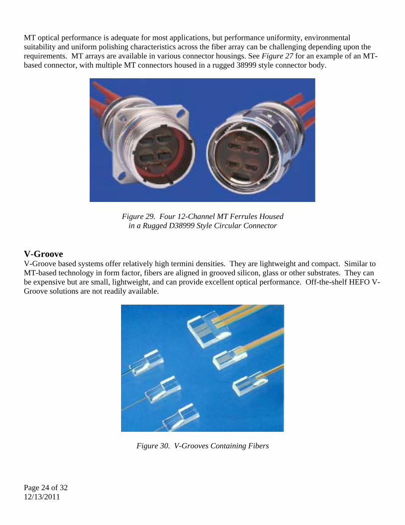
MT optical performance is adequate for most applications, but performance uniformity, environmental suitability and uniform polishing characteristics across the fiber array can be challenging depending upon the requirements. MT arrays are available in various connector housings. See Figure 27 for an example of an MT-based connector, with multiple MT connectors housed in a rugged 38999 style connector body.
Figure 29. Four 12-Channel MT Ferrules Housed in a Rugged D38999 Style Circular Connector
V-Groove V-Groove based systems offer relatively high termini densities. They are lightweight and compact. Similar to MT-based technology in form factor, fibers are aligned in grooved silicon, glass or other substrates. They can be expensive but are small, lightweight, and can provide excellent optical performance. Off-the-shelf HEFO V-Groove solutions are not readily available.
Figure 30. V-Grooves Containing Fibers

Page 25 of 32 12/13/2011
Expanded Beam Expanded beam connectors offer cleaning ease and less susceptibility to small particles of dust and dirt than physical contact connectors. Moderate optical performance and moderate tolerance to shock and vibration characterize expanded beam connector performance. Expanded beam connectors usually have a lens on or near the end of the fiber. The optical signal is dramatically expanded via this optical element or lens and is usually collimated. Expanded beam signal transmission typically traverses free space. However, this technology can be susceptible to moisture condensation, fingerprints, and hydrocarbon/oil based film on the lenses, each of which can create insertion loss issues. Beam expansion is realized via multiple means including balls lens, aspheric lens, plano-convex lens, grin lens, expanded fiber cores, and lensed fiber end face geometries. Figure 29 shows a cross-sectional depiction of a ball lens based expanded beam connector and connection. Note that the ball lenses in light blue are separated by a gap.
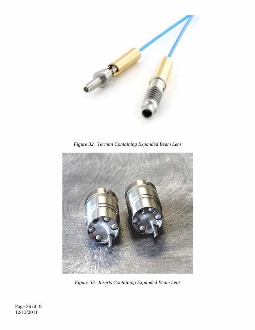
Figure 31. Expanded Beam (EB) Connector Cross-Section Expanded beam connectors can be designed with the lens as part of the fiber, the lens held within an insert, or with individual termini containing a lens. Most lenses used in HEFO applications are a glass such as BK7, LaSFN9, AL2O3, or LaSF35 but molded lenses are a viable option. See Figures 30 and 31 for lensed termini and inserts containing lenses.
Page 26 of 32 12/13/2011
Figure 32. Termini Containing Expanded Beam Lens
Figure 33. Inserts Containing Expanded Beam Lens

Page 27 of 32 12/13/2011
Beam alignment is critical to optical insertion loss performance. As shown by the rate of increasing insertion loss in Graph 1, beam offset, labeled ball-to-ball, is less critical than angular beam alignment (tilt) or lens-to-fiber (ferrule-to-ball) alignment.
Graph 1. Relative Expanded Beam Alignment Sensitivities

Page 28 of 32 12/13/2011
Examples of harsh environment expanded beam connectors include: TACBeam (MIL-PRF-83526/20 & /21) The TacBeam expanded beam connector is 4-channel and offers the MIL specified insertion loss of 2.0 dB in multimode and 2.5 dB in single mode. The connector is dust tolerant, hermaphroditic, terminates to various cables, and can be readily cleaned of debris. Currently, there are no qualified (QPL) suppliers of this product.
Figure 34. TACBeam Expanded Beam Plug Connector CTOS The CTOS expanded beam connector is stainless steel in construction, has a window to protect the lens elements, and is available in multimode and single mode versions. This rugged connector for the tactical market is widely used in multiple harsh environments and markets.
Figure 35. The Windowed CTOS Expanded Beam Connector

Page 29 of 32 12/13/2011
Example of a HEFO Connector Selection Trade Study Defined requirements enable connector selection trade studies. Typically, a table is built comparing the various attributes of multiple fiber optic connectors versus the requirements. Each requirement can be weighed according to importance. Connector selection and justification is based on such a trade study. Suppose an aerospace platform requires a single mode fiber optic connection with multiple fibers. Requirements include superior optical performance, low back reflection, and moderate weight in a very high shock and vibration environment. Various types of existing connectors are compared in Table 4 using the limited set of requirements listed below.
• Aerospace platform • Multiple single mode fibers • Superior insertion loss performance • Low back reflection • High vibration and shock • MIL temperature range • RF-over-fiber / sensor application • Low-moderate weight

Page 30 of 32 12/13/2011
Connector/Technology Importance Rating 38999 ARINC 801 MT Based Expanded Beam M28876 THD Tactical/Herm NGConn V-Groove Commercial
Technology Ferrule Based Physical Contact
Ferrule Based Physical Contact
Linear Fiber Array, Direct Fiber
ContactExpanded Beam Ferrule Based
Physical ContactFerrule Based
Physical ContactFerrule Based
Physical ContactFerrule Based
Physical Contact
Linear Fiber Array, Direct Fiber
Contact
Ferrule Based,Physical Contact
Termini M29504/4 & /5 ARINC 801 NA NA M29504/14 & /15 AFSI Airframe TFOCA-II, Airframe M29504/18 NA VariousFerrule Diameter (mm) 1.6 1.6 NA NA 2 1.25 1.25, 2.5 1.25 NA 1.25, 2.5Termini Capacity (PC/UPC) 61 Various Multiples of 8/12 Set by lens diameter 31 72 24 36 Multiples of 8/12 VariousAPC Capable No Yes Yes Yes/No Yes Yes Yes Yes Yes Yes/NoSpring Force (nominal) 1.75 1.25 NA NA 4 - 7 Lbs 1.5 3.8 Lbs 3 Lbs NA <= 1.5 lbsInsert-to-Insert Bottoming No Yes/No No Yes Yes Yes Yes Yes Yes Yes/NoTermini Density 2 4 4 5 2 3 4 2 3 5 1Design Maturity 1 5 4 2 3 5 4 5 3 2 5Insertion Force (max population) 1 2 2 4 5 3 2 3 3 4 4Sealed Termini No No No Yes Yes Yes Yes Yes No Yes/NoCable Construction Many Many Ribbon Many Many/Shipboard Many Many/Tactical Many Ribbon ManyFiber Count/Cable 1 4 4 5 3 3 4 3 4 5 1Cable Bend Radius 1 3 3 3 3 3 2 3 3 3 3Cable Diameter/Size 1 3 3 4 3 3 2 3 3 4 2Optical Performance (IL)Cost 1 4 3 4 3 3 2 3 3 2 5Availability 1 5 3 2 3 4 4 5 3 2 5Risk 1 3 3 2 3 4 4 4 4 3 2Environmental
Salt Fog 2 4 3 3 3 4 3 3 4 3 3Rain 2 3 3 3 2 4 3 4 4 3 3Dust 2 3 3 3 4 3 3 3 3 3 3Humidity 2 3 3 3 2 4 3 4 4 3 2Vibration 2 5 4 2 3 4 3 3 5 2 2Shock 2 2 3 2 2 5 3 4 5 2 1Temperature 2 2 3 2 2 3 3 3 3 2 3
Reliability (Overall)Mating Durability 2 3 4 2 5 4 4 4 4 1 2Corrosion Resistance 2 3 3 3 3 3 3 3 3 3 3
Maintenance/Logistics/Ease of UseCleaning Ease 1 3 4 3 5 3 3 4 4 3 5Installation Ease 1 3 2 3 3 3 2 3 3 3 4Repairability 1 4 4 2 2 4 3 4 4 2 4
Mechanical/DimensionalWeight 1 3 3 5 3 3 2 2 3 4 5Size 1 3 3 5 3 3 1 2 3 4 5
Totals 109 107 100 98 118 99 110 119 95 96
Comparative or Relative Fiber Optic Connection Attributes (Higher is Better)
Table 4. HEFO Connector Trade Study

Page 31 of 32 12/13/2011
Each connector or cable assembly attribute includes an importance rating factor based on the requirements. Though not specifically described or presented as part of this paper, commercial-off-the-shelf (COTS) single channel connectors were included in the trade table. In the example connector selection trade study table, the NGCon connector rates highest and is the connector of choice. Tools and Termination Requirements A final area of HEFO connector selection (or design) centers on training, trouble shooting, maintenance and support. A myriad of questions impacting connector selection in this realm may be considered, including:
• Are damaged connectors repaired or replaced? • Will the connectors be repaired or replaced in the field, depot or factory? • What levels of training are required by the installer, user and/or repair technician? • What is the maintenance plan for the assemblies? • How are the cables/connectors to be inspected and tested? • Is power required and available during installation, inspection, maintenance and/or
repair? • What tools are needed for installation/repair/replacement? • What is the recommended connector cleaning process? • How easy is it to clean the connector? • What is mean-time-to-repair? • How are faults isolated? • Are removable termini required?
A typical fiber optic termination and repair kit is shown in Figure 36.
Figure 36. Fiber Optic Termination and Repair Kit

Page 32 of 32 12/13/2011
Conclusion Harsh environment fiber optic connector selection must be based on well-defined and understood requirements. Performance, environment and physical constraints each contribute to HEFO connector selection. For optimal performance, designers should perform disciplined system and interconnect trade studies to help identify products and technologies suitable for the intended applications.
Company Overview
Amphenol Fiber Systems International (AFSI), a division of Amphenol, provides reliable and innovative fiber optic interconnect solutions that withstand the harsh environments of military (ground systems, avionics, and shipboard), energy and broadcast applications. After more than 18 years in business, AFSI maintains its position as a global leader in fiber optic interconnect components and systems such as termini, M28876, 38999 assemblies, MIL-ST, TFOCA and the TFOCA-II® connector, which AFSI developed and patented. AFSI has delivered millions of fiber optic connectors in more than 34 countries. Whenever there is a need for superior cost-effective fiber optic systems and products that will stand up to demanding operating environments, you can rely on AFSI for engineering know-how, top-quality products and expert technical support.
Amphenol Fiber Systems International 1300 Central Expressway N, #100
Allen, TX 75013 T: (214) 547-2400 F: (214) 547-9344
www.fibersystems.com [email protected]
About the Author
William (Bill) Reid is currently Vice President of Product Development, responsible for engineering and product management. He has been with AFSI for 9 years and has spent the past 11 years working in various capacities in fiber optic product development. Prior to his tenure at AFSI, Bill spent 20 years with Texas Instruments Systems Group, now a part of Raytheon, in various design and management positions. Bill holds a Bachelor’s Degree in Mechanical Engineering from Michigan State University.