hases in rass characterization of the microstructural ... · a nikon epiphot 300 light microscope....
TRANSCRIPT
B I O G R A P H YGeorgios Pantazopoulosis a chemical engineerfrom the National Tech-nical University ofAthens (NTUA) with aspecialization in materi-als science. He receivedhis PhD from the Mechanical EngineeringDepartment of NTUA in the field of manu-facturing technology of advanced materialsin 1999. In the past he served as Quality Con-trol Manager at various plants of HalcorMetal Works in Greece. He is now a seniorresearch project leader at the ELKEME R&DCentre of the Viohalco Group of Companies.His main scientific research interests are inthe field of failure analysis, materials pro-cessing, mechanical testing and tribology.
A B S T R A C TFree-machining a-b brasses are widely usedas raw materials for the fabrication of com-ponents used in a broad spectrum of tech-nological applications. Their exceptionalfree-cutting properties are attributed tovarious microstructural features of thematerial, such as Pb-particle and a-b phasedistribution characteristics. The majormicrostructural characteristics of leaded a-bbrass (CW614N-Cu58Zn39Pb3) rods havebeen studied using light and scanning elec-tron microscopy. Critical parameters such asparticle population density and specificinterphase boundary lengths are discussedwith respect to the resultant machinabilityperformance.
K E Y W O R D Sreflect light microscopy, scanning electronmicroscopy, energy-dispersive X-ray spec-troscopy, a-b brass, machinability, phasestructure, lead distribution
A C K N O W L E D G E M E N T SThe authors wish to express their thanks toMr A. Rikos and Mr A. Toulfatzis for theirvaluable contribution to the completion ofthe experimental work.
A U T H O R D E TA I L SDr Georgios Pantazopoulos, ELKEME Hellenic Research Centre for Metals,252 Pireaus Str., 17778 Athens, GreeceTel. +30 210 489 8263 Email: [email protected] Microscopy and Analysis 22(5):13-16 (EU), 2008
a-b PH A S E S I N BR A S S
I N T R O D U C T I O NLeaded brass bars are used extensively in appli-cations varying from decoration and architec-ture to electrical, electronic and mechanicalengineering. The bars are used to produceparts such as screws, nuts, bolts, fittings andhydraulic components mainly by automaticmachining operations. The chemical composi-tion of these alloys and especially the lead con-tent (Pb content: 2.5-3.5% wt) offers superiorperformance in high-speed machining, i.e. cut-ting, milling and drilling operations, since itserves as a chip-breaking constituent leadingto an excellent surface aspect with the mini-mum possible tool wear. The addition of leaddecreases the cutting forces, lowering the chipductility and producing segmented machiningchips. Furthermore, lead concentrated at thetool/workpiece interface significantly reducesthe friction coefficient and prevents stickingand seizure, thereby extending tool life [1].
Dual-phase brass microstructure comprisesalpha (a) and beta (b) phases: the alpha phaseis a fcc solid solution, and the beta is the inter-metallic non-stoichiometric CuZn compoundhaving a bcc crystal structure.
The general production processes (castingand metal forming) along with a generalmachinability evaluation of the brass rods andthe relevant standards have been presented[2, 3]. The major in-process and in-service con-ditions (and failures and their causes) of the
brass rods and their related components havebeen reviewed [4].
Machinable brass contains lead above 2%wt. However, lead contents ranging from 2.5to 3.5% render the alloy exceptionally machin-ing efficient which can be evaluated with thefollowing criteria:• Tool wear rate – expected/measured tool
life (Taylor equation [1])• Surface finish• Machined work piece dimensional
tolerances• Cutting forces• Machining chip sizeIn this study, the principal microstructural
features of leaded a-b brass (CW614N-Cu58Zn39Pb3) are highlighted and discussedin relation to behaviour during machining.
M AT E R I A L S A N D M E T H O D SMaterialsThe composition of the examined materialwas checked by optical emission spectrometryand electrolysis and is presented in Table 1,where it is compared with the standard speci-fication EN 12164:1998 [5].
Specimen Preparation Microstructural and morphological character-ization was conducted using mounted cross-sections made parallel and transverse to theextrusion direction. Grinding was performed
Characterization of the MicrostructuralAspects of Machinable a-b Phase Brass G. Pantazopoulos and A. Vazdirvanidis, ELKEME Hellenic Research Centre for Metals, Athens, Greece
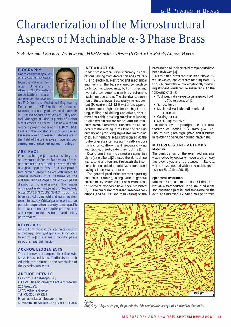
Figure 1: Brightfield reflected light micrograph of a longitudinal section of the as-cast brass billet showing a typical Widmanstätten phase structure.
MICROSCOPY AND ANALYSIS SEPTEMBER 2008 13
using successive abrasive SiC papers, followedby fine polishing using diamond and silica sus-pensions, respectively. Rinsing in alcohol anddrying in a hot air stream were used as finish-ing procedures. To reveal the phase structure,immersion etching was performed using ferricchloride solution made by dissolving 8.3 gFeCl3 in 10 ml HCl and 90 ml H2O.
Light and Electron MicroscopyMetallographic studies were performed usinga Nikon Epiphot 300 light microscope. Sampleswere examined in brightfield and darkfieldreflected light modes using 103 NA 0.3, 203NA 0.46, 503 NA 0.8 and 1003 NA 0.9 objec-tives. Images were taken with a Nikon DigitalNet DN100 camera with 1.3 megapixals reso-lution and then processed using Image-ProPlus image analysis software
Scanning electron microscope observationsof the fracture surface were conducted at20kV with an FEI (Philips) XL40 Shottky field-emission gun scanning electron microscopeequipped with secondary and backscatteredelectron detectors and an EDAX energy-dis-persive X-ray spectroscopy (EDS) system forsurface elemental analysis.
Hardness TestingThe material’s temper was confirmed byemploying hardness testing using an Instron-Wolpert NT1100 Vickers indentation deviceunder 49,05 N applied load, according to ENISO 6507 standard [6].
C H A R A C T E R I Z AT I O N O F B R A S SM I C R O S T R U C T U R E The microstructure of the as-cast brass billets isshown in Figure 1. The cast structure is charac-terized by a typical Widmanstätten morphol-ogy consisting of a-intersecting crystals in a b-phase matrix, which has resulted from solidifi-
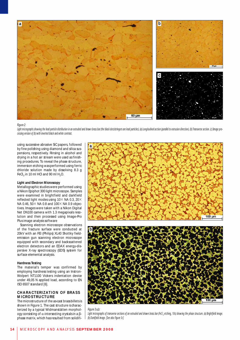
Figure 2: Light micrographs showing the lead particle distribution in an extruded and drawn brass bar (the black dots/stringers are lead particles). (a) Longitudinal section (parallel to extrusion direction). (b) Transverse section. (c) Image pro-cessing version of (b) with inverted black and white contrast.
MICROSCOPY AND ANALYSIS SEPTEMBER 200814
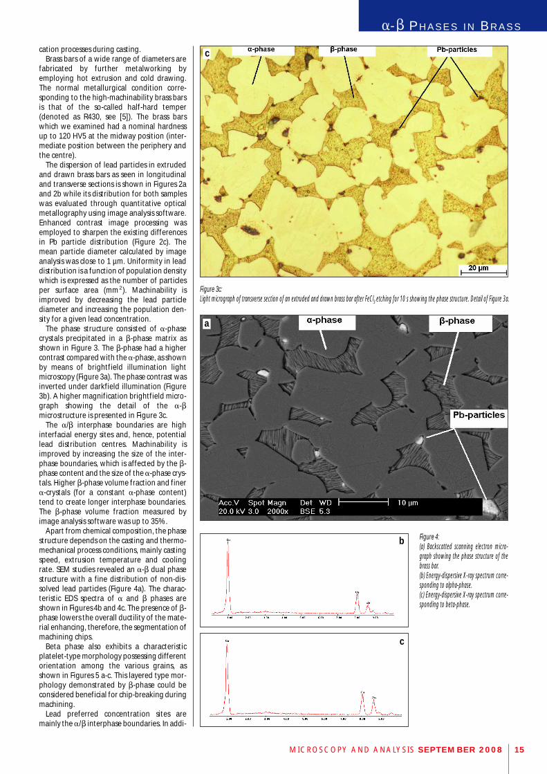
Figure 3 a,b: Light micrographs of transverse sections of an extruded and drawn brass bar (FeCl3 etching, 10s) showing the phase structure. (a) Brightfield image.(b) Darkfield image. [See also Figure 3c]
a b
c
a
b
a-b PH A S E S I N BR A S S
cation processes during casting. Brass bars of a wide range of diameters are
fabricated by further metalworking byemploying hot extrusion and cold drawing.The normal metallurgical condition corre-sponding to the high-machinability brass barsis that of the so-called half-hard temper(denoted as R430, see [5]). The brass barswhich we examined had a nominal hardnessup to 120 HV5 at the midway position (inter-mediate position between the periphery andthe centre).
The dispersion of lead particles in extrudedand drawn brass bars as seen in longitudinaland transverse sections is shown in Figures 2aand 2b while its distribution for both sampleswas evaluated through quantitative opticalmetallography using image analysis software.Enhanced contrast image processing wasemployed to sharpen the existing differencesin Pb particle distribution (Figure 2c). Themean particle diameter calculated by imageanalysis was close to 1 µm. Uniformity in leaddistribution is a function of population densitywhich is expressed as the number of particlesper surface area (mm2). Machinability isimproved by decreasing the lead particlediameter and increasing the population den-sity for a given lead concentration.
The phase structure consisted of a-phasecrystals precipitated in a b-phase matrix asshown in Figure 3. The b-phase had a highercontrast compared with the a-phase, as shownby means of brightfield illumination lightmicroscopy (Figure 3a). The phase contrast wasinverted under darkfield illumination (Figure3b). A higher magnification brightfield micro-graph showing the detail of the a-bmicrostructure is presented in Figure 3c.
The a/b interphase boundaries are highinterfacial energy sites and, hence, potentiallead distribution centres. Machinability isimproved by increasing the size of the inter-phase boundaries, which is affected by the b-phase content and the size of the a-phase crys-tals. Higher b-phase volume fraction and finera-crystals (for a constant a-phase content)tend to create longer interphase boundaries.The b-phase volume fraction measured byimage analysis software was up to 35%.
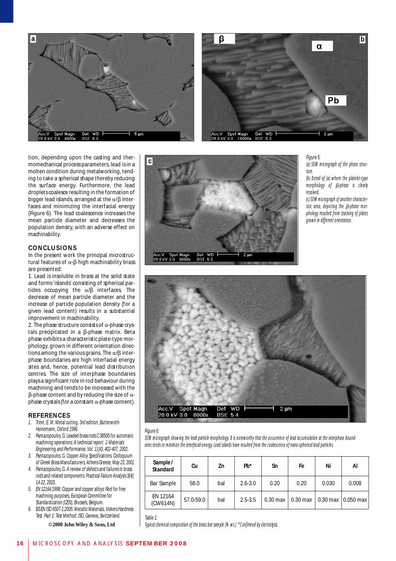
Apart from chemical composition, the phasestructure depends on the casting and thermo-mechanical process conditions, mainly castingspeed, extrusion temperature and coolingrate. SEM studies revealed an a-b dual phasestructure with a fine distribution of non-dis-solved lead particles (Figure 4a). The charac-teristic EDS spectra of a and b phases areshown in Figures 4b and 4c. The presence of b-phase lowers the overall ductility of the mate-rial enhancing, therefore, the segmentation ofmachining chips.
Beta phase also exhibits a characteristicplatelet-type morphology possessing differentorientation among the various grains, asshown in Figures 5 a-c. This layered type mor-phology demonstrated by b-phase could beconsidered beneficial for chip-breaking duringmachining.
Lead preferred concentration sites aremainly the a/b interphase boundaries. In addi-
Figure 4: (a) Backscatted scanning electron micro-graph showing the phase structure of thebrass bar. (b) Energy-dispersive X-ray spectrum corre-sponding to alpha-phase. (c) Energy-dispersive X-ray spectrum corre-sponding to beta-phase.
MICROSCOPY AND ANALYSIS SEPTEMBER 2008 15
Figure 3c: Light micrograph of transverse section of an extruded and drawn brass bar after FeCl3 etching for 10 s showing the phase structure. Detail of Figure 3a.
a
b
c
c
MICROSCOPY AND ANALYSIS SEPTEMBER 200816
Figure 6: SEM micrograph showing the lead particle morphology. It is noteworthy that the occurrence of lead accumulation at the interphase bound-aries tends to minimize the interfacial energy. Lead islands have resulted from the coalescence of nano-spherical lead particles.
Table 1: Typical chemical composition of the brass bar sample (% wt.) *Confirmed by electrolysis.
Sample /Standard Cu Zn Pb* Sn Fe Ni Al
Bar Sample 58.0 bal 2.6-3.0 0.20 0.20 0.030 0.008
EN 12164(CW614N) 57.0-59.0 bal 2.5-3.5 0.30 max 0.30 max 0.30 max 0.050 max
Figure 5: (a) SEM micrograph of the phase struc-ture.(b) Detail of (a) where the platelet-typemorphology of b-phase is clearlyresolved.(c) SEM micrograph of another character-istic area, depicting the b-phase mor-phology resulted from stacking of platesgrown in different orientation.
tion, depending upon the casting and ther-momechanical process parameters, lead is in amolten condition during metalworking, tend-ing to take a spherical shape thereby reducingthe surface energy. Furthermore, the leaddroplets coalesce resulting in the formation ofbigger lead islands, arranged at the a/b inter-faces and minimizing the interfacial energy(Figure 6). The lead coalescence increases themean particle diameter and decreases thepopulation density, with an adverse effect onmachinability.
C O N C L U S I O N SIn the present work the principal microstruc-tural features of a-b high machinability brassare presented:1. Lead is insoluble in brass at the solid stateand forms ‘islands’ consisting of spherical par-ticles occupying the a/b interfaces. Thedecrease of mean particle diameter and theincrease of particle population density (for agiven lead content) results in a substantialimprovement in machinability.2. The phase structure consists of a-phase crys-tals precipitated in a b-phase matrix. Betaphase exhibits a characteristic plate-type mor-phology, grown in different orientation direc-tions among the various grains. The a/b inter-phase boundaries are high interfacial energysites and, hence, potential lead distributioncentres. The size of interphase boundariesplays a significant role in rod behaviour duringmachining and tends to be increased with theb-phase content and by reducing the size of a-phase crystals (for a constant a-phase content).
R E F E R E N C E S1. Trent, E. M. Metal cutting, 3rd edition, Butterwoth-
Heinemann, Oxford 1996.2. Pantazopoulos, G. Leaded brass rods C 38500 for automatic
machining operations: A technical report. J. MaterialsEngineering and Performance, Vol. 11(4): 402-407, 2002.
3. Pantazopoulos, G. Copper Alloy Specifications. Colloquiumof Greek Brass Manufacturers, Athens Greece, May 23, 2001
4. Pantazopoulos, G. A review of defects and failures in brassrods and related components. Practical Failure Analysis 3(4):14-22, 2003.
5. EN 12164:1998: Copper and copper alloys: Rod for freemachining purposes, European Committee forStandardization (CEN), Brussels, Belgium.
6. BS EN ISO 6507-1:2005: Metallic Materials. Vickers HardnessTest. Part 1: Test Method. ISO, Geneva, Switzerland.
©2008 John Wiley & Sons, Ltd
a b
c