hastings district council · motsam manual of traffic signs and markings ... section 3 location:...
TRANSCRIPT

Hastings District Council Whakatu Arterial Link
Project Description
June 2014

GHD | - Whakatu Arterial Link Link Project Description | i
Table of contents 1. Introduction..................................................................................................................................... 1
1.1 Purpose and Scope of this Document ................................................................................. 1 1.2 The Whakatu Arterial Project ............................................................................................... 1
1.3 Abbreviations ....................................................................................................................... 2
1.4 Structure of this Document .................................................................................................. 3
2. Background Information ................................................................................................................. 3
2.1 HPTS.................................................................................................................................... 3 2.2 Enquiry by Design (EBD) Process ....................................................................................... 4
3. Location .......................................................................................................................................... 7
3.1 Project Location and Description of Route .......................................................................... 7
3.2 Affected properties ............................................................................................................... 8
4. Road Design .................................................................................................................................. 9 4.1 Investigations informing design ........................................................................................... 9
4.2 Pavement Design ............................................................................................................... 11
4.3 Alignment detail ................................................................................................................. 11
4.4 SH2, Pilcher Road and Napier Road Intersection ............................................................. 13
4.5 Pakowhai Road Intersection .............................................................................................. 14 4.6 Local Road Intersections ................................................................................................... 15
4.7 Farndon Road Intersection ................................................................................................ 16
4.8 Rail Level Crossing Design ................................................................................................ 17
4.9 Closure of the Ruahapia Road Level Crossing ................................................................. 17
4.10 Cycleways .......................................................................................................................... 18 4.11 Karamu Stream Bridge Design .......................................................................................... 18
4.12 Stormwater Design ............................................................................................................ 21
4.13 Street Lighting Design........................................................................................................ 22
5. Project Construction ..................................................................................................................... 23
5.1 Construction Environmental Management Plan ................................................................ 23 5.2 Project Construction Schedule .......................................................................................... 23
5.3 Construction overview........................................................................................................ 24
5.4 Construction workforce ...................................................................................................... 26
5.5 Hours of construction work ................................................................................................ 26
5.6 Property access ................................................................................................................. 26
5.7 Temporary facilities ............................................................................................................ 27 5.8 National Environmental Standards on Air Quality ............................................................. 27
5.9 Earthworks ......................................................................................................................... 27
5.10 Potential impacts from construction ................................................................................... 27
6. Operation and Maintenance ......................................................................................................... 30
6.1 Operation ........................................................................................................................... 30

ii | GHD | Whakatu Arterial Link Link Project Description 51/31468/
6.2 Maintenance ...................................................................................................................... 30
6.3 Potential impacts from operation and maintenance .......................................................... 31
7. Basis of Report ............................................................................................................................. 37
Table index Table 1: Summary of Total Land Requirements ...................................................................................... 8
Table 2 Design Traffic Assumptions – Whakatu Arterial ................................................................ 10
Table 3– Traffic Multipliers used in CIRCLY Pavement Design Software ............................................. 11
Table 4: Street Lighting Design Summary ............................................................................................. 23
Table 5 Accident Cost Summary ............................................................................................................ 32
Table 6 Do Minimum and Project 2026 Annual Daily Traffic Flows ....................................................... 32
Table 7 Waahi Tapu Sites ...................................................................................................................... 35
Figure index Figure 1: Route options identified in the HPTS ........................................................................................ 4
Figure 2 Route Alignment ......................................................................................................................... 6
Figure 3: Indicative route location ............................................................................................................ 7
Figure 4: Typical cross section ............................................................................................................... 12
Figure 5: Indicative layout of SH2 / Whakatu Arterial / Napier Rd Roundabout .................................... 13
Figure 6: Indicative layout of Pakowhai Rd / Whakatu Arterial Roundabout ......................................... 14
Figure 7 Whakatu Road Intersection ...................................................................................................... 15
Figure 8: Farndon Road Intersection Improvements - Preferred Option 4 Layout ................................. 17
Figure 9 Karamu Stream Cross Section with Bridge.............................................................................. 19
Figure 10 Cross Section of Karamu Stream Bridge ............................................................................... 20
Figure 11 Minimum Swale Cross Section .............................................................................................. 22
Figure 12 Location of Waahi Tapu Sites (1) ........................................................................................... 36
Figure 13 Location of Waahi Tapu Sites (2) ........................................................................................... 36
Appendices Appendix A - Technical Drawings
Appendix B – Lighting Subcategory Evaluation
Appendix C – HBRC Spill Management Plan

GHD | Report for Hastings District Council - Whakatu Arterial Link, 51/31468/ | 1
1. Introduction 1.1 Purpose and Scope of this Document
The Project Description Report (PDR) has been prepared to describe the proposed Whakatu Arterial Link (WAL) between SH2 North and Pakowhai Road near Hastings. It outlines the approach taken to select a preferred road alignment, the investigations conducted to inform key design decisions, and details of road design and location including key design elements such as major intersections and the crossing of the Karamu Stream.
This PDR will be used as the basis for applications under the Resource Management Act 1991 (RMA) to designate the proposed route and other related resource consents.
This document does not assess the impacts of construction or operation of the proposed road on the environment. It does however describe and quantify the project such that others may assess these impacts. To that end, separate environmental effects studies have been undertaken by others using the parameters set out in this document.
A Stormwater Management Plan (GHD 2014g) and Erosion and Sediment Control Plan (GHD 2014h) and a draft Construction Environmental Management Plan (GHD 2014i) have been developed and are included with the RMA application documentation. At such time as the WAL proceeds to the construction phase, these plans will be included in tender documentation together with copies of conditions imposed under the RMA.
1.2 The Whakatu Arterial Project
The WAL has been identified in the Hawke’s Bay Regional Land Transport Strategy 2012 - 2042 short term programme.
The WAL provides a strategic link between SH2 North and Pakowhai Road with a view to achieving the overall objectives of the WAL, which are to:
“…enhance and improve the safety and efficiency of the transport network of the district and region so as to:
• Improve accessibility for individuals and businesses and support economic growth and productivity;
• Provide convenient, efficient and safe access for freight movements to and from the Whakatu Industrial Area;
• Promote the use of the Hawkes Bay Expressway for the road transport of freight and vehicles between the Whakatu Industrial Area and the Port of Napier;
• Provide convenient, efficient and safe access between Havelock North and the Napier/Hastings Airport and Napier’s north western employment and residential areas; and
• Enhance the safety of the Whakatu residential area by reducing freight movements through it.”
2 | GHD | Whakatu Arterial Link Link Project Description 51/31468/
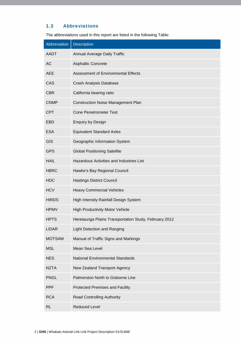
1.3 Abbreviations
The abbreviations used in this report are listed in the following Table:
Abbreviation Description
AADT Annual Average Daily Traffic
AC Asphaltic Concrete
AEE Assessment of Environmental Effects
CAS Crash Analysis Database
CBR California bearing ratio
CNMP Construction Noise Management Plan
CPT Cone Penetrometer Test
EBD Enquiry by Design
ESA Equivalent Standard Axles
GIS Geographic Information System
GPS Global Positioning Satellite
HAIL Hazardous Activities and Industries List
HBRC Hawke’s Bay Regional Council
HDC Hastings District Council
HCV Heavy Commercial Vehicles
HIRDS High Intensity Rainfall Design System
HPMV High Productivity Motor Vehicle
HPTS Heretaunga Plains Transportation Study, February 2012
LIDAR Light Detection and Ranging
MOTSAM Manual of Traffic Signs and Markings
MSL Mean Sea Level
NES National Environmental Standards
NZTA New Zealand Transport Agency
PNGL Palmerston North to Gisborne Line
PPF Protected Premises and Facility
RCA Road Controlling Authority
RL Reduced Level

GHD | Report for Hastings District Council - Whakatu Arterial Link, 51/31468/ | 3
Abbreviation Description
RLTS Regional Land Transport Strategy
RMA Resource Management Act (1991)
SH State Highway
SSTMP Site Specific Traffic Management Plan
TCD Traffic Control Devices
vpd Vehicles per day
vph Vehicles per hour
1.4 Structure of this Document
This report is presented in six sections briefly described as follows:
Section 1 Introduction: Provides an introduction to the project and description of the overall project objectives.
Section 2 Background Information: Describes where the project fits within the HPTS and RLTS and summarises previous consultation and processes undertaken to develop the recommended alignment.
Section 3 Location: Provides a high level description of the route and key factors influencing the design.
Section 4 Road Design: Describes the key design elements, standards and constraints
Section 5 Project Construction: Describes a high level overview of how the project will be constructed and how constructions effects are to be managed
Section 6 Operation and Maintenance: Provides a description of long term operational effects of the project, ongoing maintenance and monitoring requirements.
Appendices: The following appendices are attached to this report:
Appendix A Technical Drawings – provides detail designed information for the alignment, typical cross sections, intersection design and bridge design (etc)
Appendix B Lighting Subcategory Evaluation – provides lighting design sub-category evaluation
Appendix C Hawkes Bay Regional Council Spill management plan
2. Background Information 2.1 HPTS
The 2012 HPTS was formally adopted by the Council in April 2012. The aim was to:
“ensure that people and goods are moved to/from and within the study area with the least cost and for the most benefit to the region’s economy while enhancing its social and cultural fabric and environmental condition”.
The HPTS informed the Hawkes Bay Regional Land Transport Strategy for 2012 - 2042 which identified the WAL as a priority project for the short term (2012-2017) programme.

4 | GHD | Whakatu Arterial Link Link Project Description 51/31468/
For initial assessment purposes, the HPTS considered three options (referred to as Options 22, 23 and 24) for an improved link between Whakatu and Pakowhai Road. The aim of this link is to improve access for freight from the growing industrial area at Whakatu along the Expressway to the Port of Napier, as well as providing a link from the hinterlands to the Whakatu industrial area. The three options were evaluated against economic and environmental factors. Option 24 (indicated in yellow on Figure 1 below) was ultimately identified in the HPTS as the preferred option.
Figure 1: Route options identified in the HPTS
Option 24 was preferred because it provides the most direct route between the SH2/Napier Rd roundabout and Pakowhai Road than the alternatives, being more attractive for traffic from Havelock North and more closely aligned with the strategic objectives of the WAL.
2.2 Enquiry by Design (EBD) Process
To refine and develop route options based on a wider appreciation of values and impacts, an EBD process was initiated by the Hastings District Council. The EBD process was a collaborative, community driven design process to explore and test different design and development ideas and options based on a comprehensive understanding of local issues, opportunities and constraints. A working group was established for the process involving community members (including businesses, landowners and environmentalists), Council staff and consultants. The overall objective of this working group was to develop the WAL from an initial concept to a preferred route option ready for consideration by the full Council.
This process is more fully described in the Alternatives Assessment Report (EMS 2014b) which also includes a copy of the Enquiry by Design Working Group Report.
In summary, the recommendations from the EBD Working Group were:
“…that the Hastings District Council accept the refined Option 3 (as shown in Appendix J of the Working Group Report) as the preferred route option for the Whakatu Arterial Link. Option 3 is recommended because it provides:

GHD | Report for Hastings District Council - Whakatu Arterial Link, 51/31468/ | 5
• improved safety for the Whakatu community by drawing traffic off residential streets and around the Mangateretere School location;
• improved safety at the SH2 and Pakowhai Road intersections;
• better connectivity to the industrial area;
• better economics as indicated by higher BCR and FYRR values;
• good potential to incorporate cycle lanes and walkways;
• an attractive route from Havelock North to Napier and the airport; and
• clear sight lines and geometry.
Given this recommendation, the Working Group also makes the following additional recommendations and comments to the Hastings District Council and it is requested that these are considered in any decision on the development of Option 3 for designation, detailed design and construction:
• Include an extended Anderson Road and roundabout on the Arterial;
• The extension of Anderson Road with a new bridge across the Karamu Stream to link to Otene Road and a strategic link through to the NE Connecter should be considered by HDC and the Regional Transport Committee;
• The design around the Pilcher Road / SH2 intersection is a key safety issue which must be well addressed in detailed design, particularly around the Mangateretere School;
• The design of the Pakowhai Rd arterial intersection is a key design issue and requires effective and safe linkages with Farndon Rd and Ruahapia Rd;
• Through design and traffic management, discourage the use of Farndon Rd as a heavy traffic route to Napier and the Port, but not to Awatoto;
• Any final design needs to look at maintaining efficient land use as much as possible and minimising the loss of fertile land;
• Maintaining good access to the Pakowhai Country Park will be an important design consideration for intersections in the Pakowhai / Ruahapia or Chesterhope Bridge area;
• Consider opportunities for discouraging the use of alternative, less-efficient routes (rat runs) and utilisation of closed roads for cycle / walkways; and
• If there are any road closures, road names will need to be altered to help with prompt identification and access for emergency services.”
The Hastings District Council accepted the recommendations from the EBD Working Group and Option 3 has been confirmed as the preferred alignment to proceed to detailed design 7 August 2012. The final alignment confirmed through detailed design is shown in Figure 2 below. This alignment includes design refinements developed in consultation with landowners, the EBD Working Group, and the broader community. This process is fully explained in the Alternatives Assessment Report (EMS 2014b).

6 | GHD | Whakatu Arterial Link Link Project Description 51/31468/
Figure 2 Route Alignment
Proposed Road Closure
Pakowhai Road

GHD | Report for Hastings District Council - Whakatu Arterial Link, 51/31468/ | 7
3. Location 3.1 Project Location and Description of Route
The WAL is located within the Hastings District and extends between Pakowhai Road and SH2 to the North East of Hastings Township. The adjacent land use is predominantly industrial with horticultural properties located towards the eastern and western ends of the alignment. The general location of the project is indicated in Figure 3 below. A detailed route alignment is shown in Figure 2, (Section 2 of this report).
Figure 3: Indicative route location
8 | GHD | Whakatu Arterial Link Link Project Description 51/31468/
The route is approximately 3,500m long and is orientated in a general north-west/south-east direction extending from the west at Pakowhai Road near the closed-off Rangitane Road, through to the intersection of SH2 with Napier Road to the east.
The alignment crosses the Karamu Stream 400 to 450m east of Pakowhai Road and from there continues on the northern side of this stream. The WAL intersects with one local road, this being Whakatu Road. The Whakatu Road intersection will be a 4 legged roundabout.
Whakatu Road is classified as a local road in the operative and proposed Hastings District Plan.
The existing rural environment has a posted speed limit of 80 km/h. This speed limit changes to 50km/h within the Whakatu urban area. On Anderson Road, this reduction occurs outside Whakatu Cold Store Limited.
The Palmerston North-Gisborne railway line (PNGL) crosses the alignment at an approximate mid-point (approximately 1,050 metres east of Pakowhai Road).
3.2 Affected properties The properties from which land will be required for the construction of the WAL are outlined in the land requirement plan in the Notice of Requirement (HDC 2014a)
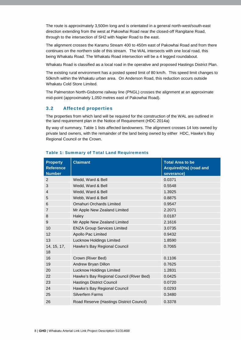
By way of summary, Table 1 lists affected landowners. The alignment crosses 14 lots owned by private land owners, with the remainder of the land being owned by either HDC, Hawke’s Bay Regional Council or the Crown.
Table 1: Summary of Total Land Requirements
Property Reference Number
Claimant Total Area to be Acquired(Ha) (road and severance)
2 Wedd, Ward & Bell 0.0371 3 Wedd, Ward & Bell 0.5548 4 Wedd, Ward & Bell 1.3925 5 Webb, Ward & Bell 0.8875 6 Omahuri Orchards Limited 0.9547 7 Mr Apple New Zealand Limited 2.2071 8 Haley 0.0187 9 Mr Apple New Zealand Limited 2.1616 10 ENZA Group Services Limited 3.0735 12 Apollo Pac Limited 0.9432 13 Lucknow Holdings Limited 1.8590 14, 15, 17, 18
Hawke’s Bay Regional Council 0.7065
16 Crown (River Bed) 0.1106 19 Andrew Bryan Dillon 0.7625 20 Lucknow Holdings Limited 1.2831 22 Hawke’s Bay Regional Council (River Bed) 0.0425 23 Hastings District Council 0.0720 24 Hawke’s Bay Regional Council 0.0293 25 Silverfern Farms 0.3480
26 Road Reserve (Hastings District Council) 0.3378

GHD | Report for Hastings District Council - Whakatu Arterial Link, 51/31468/ | 9
4. Road Design 4.1 Investigations informing design
4.1.1 Initial Geotechnical Testing
The following ground investigations were carried out:
• A total of 21 hand Augers including Scala penetrometers at various locations along the alignment; and
• Four truck mounted CPTs at the proposed bridge abutment locations, in which the data assessment also included a liquefaction assessment.
The CBR of the subgrade between depths of 250 mm to 1000 mm is typically below 4 along the majority of the proposed alignment. At certain locations the CBR trends towards a value of 1 below a depth of 1 m.
The water table is relatively high in this area.
Overall the quality and moisture content of the subgrade varies considerably along the proposed alignment.
These results show that the subgrade will require stabilisation in order to meet minimum road design requirements. It is also likely that the road pavement will require stabilisation.
Given the high water level in some locations, the road pavement will be elevated above ground to stay well clear of the water table. This will necessitate increased levels of fill and this has been reflected in detailed design drawings.
4.1.2 Pavement test pits and Laboratory Testing
Previous pavement testing had been carried out as part of investigations for improvements to the SH2 Napier Road Intersection. This data was reviewed along with the previous geotechnical investigations identified in section 4.1.1 above in order to develop an approach to pavement testing. It was determined that a total of seven test pits were required in virgin ground along the proposed route, with an additional two test pits to determine existing pavement materials on Pakowhai Road at the proposed intersection location.
Samples were collected at various locations and depths to enable laboratory testing which consisted of 14 Subgrade CBR tests compiling both natural and cement modified samples to determine the strength of the insitu material.
4.1.3 Bridge borehole investigations
A total of three boreholes were drilled to a depth of at least 20 metres at the anticipated bridge pier locations. Each location was marked and rationalised to allow access for the drilling rig.
Alluvial sand and gravels were encountered with competent material (i.e. having a Standard Penetration Test N value of 50 or more blows) being reached at depths of 11 and 12 metres. These results informed preliminary bridge design parameters, including a recommendation that piles are continual flight augered or bored cast in situ (with protective casing during excavation).
4.1.4 Test Pits for Fill Borrow areas and Laboratory Testing
HBRC have programmed widening works (for flood control purposes) for the Karamu Stream in the vicinity of the proposed WAL bridge. Through initial consultation with HBRC, it became

10 | GHD | Whakatu Arterial Link Link Project Description 51/31468/
apparent that these widening works may provide a significant quantity of fill suitable for WAL construction. This could provide a practical and environmentally sound solution in that the volume of fill being trucked in to the site could be reduced.
In order to determine the suitability of this material for use as fill, a total of six 3-4m deep test pits were dug to build on the information gathered from the bridge bore holes in an area adjacent to the Karamu Stream. Samples were collected at various locations and depths from these test pits to enable the following laboratory testing to be carried out:
• Six UCS tests to determine strength parameters;
• Three compaction curves to determine the optimal water content for maximised compaction properties.
The laboratory testing confirmed the suitability of the material for use as fill material provided it was adequately dried before placement. The relatively free draining nature of this material indicates that this will not be a problem when coupled with suitable construction methodologies.
4.1.5 Topographical Survey
A topographical survey was undertaken by “The Surveying Company” using hand held GPS. A general 20m corridor was surveyed along the proposed alignment as developed through the Enquiry by Design process with additional areas surveyed in and around proposed intersections.
Generally cross sections were spaced every 20m to 30m for green field areas and increased in frequency for areas where topography changed and areas where existing roads were being surveyed. The survey was aligned to the NZGD HB Circuit, which has a recorded mean sea level (MSL) of 0.0m.
4.1.6 Trial Pavement
A 60m x 5m trial pavement was constructed to better gauge the actual response of pavement materials in the field. Significant field testing was carried out which allowed for a 10% reduction in the thickness of the subbase materials and a 40% reduction in the basecourse layers where a heavily stabilised subbase is used.
4.1.7 Pavement Design Inputs
All design and traffic estimates followed the procedures in Austroads Guide to Pavement Technology: Part 2 Pavement Structural Design (Austroads Publication No. AGPT02/10, Austroads, 2010).
The assumptions used to estimate the design traffic are detailed in Table 1. A conservative lane distribution factor (LDF) of 1.0 was used as it is expected that most heavy vehicles will travel in the left lane only. Pavement design traffic volumes calculated from the traffic data are shown in Table 2. This design focuses on the main alignment with the highest traffic volume.
Table 2 Design Traffic Assumptions – Whakatu Arterial
Pakowhai Rd End Pilcher Rd End Estimated HCVs (2015) – assume linear growth
2787 1810
AADT (2026) 15970* 10370* Number of HCVs (2026) 2990 1920 Number of HCVs (2046) 3360 2120 LDF 1 1

GHD | Report for Hastings District Council - Whakatu Arterial Link, 51/31468/ | 11
Pakowhai Rd End Pilcher Rd End ESA per HCV 1.8** 1.8** days per year 365 365 Directional Split 50% 50% Design Life (years) 25 25 TOTAL DESIGN ESA 26 Million 17 Million
LDF = Heavy Vehicle Lane Distribution Factor
* AADT subtly different to final traffic model figures due to intersection configuration changes and pavement design not being recalculated
** Accounts for new HMPV vehicles (was 1.4 ESA per HCV before HMPV).
Table 3 details the traffic multipliers required for the different pavement material types.
Table 3– Traffic Multipliers used in CIRCLY Pavement Design Software
Material Traffic Multiplier Subgrade (vertical compressive strain) 1.17 Asphalt (tensile fatigue) 1.01 Cement Stabilised Aggregate (tensile fatigue) and foamed bitumen stabilised aggregate
2.65
4.1.8 Design subgrade CBR
Investigations with the scala penetrometer found areas of the site had low subgrade strengths of a CBR of 2%. In order to form a working platform to compact the overlying pavement layers the subgrade was stabilised with 2% cement. After stabilisation the subgrade was retested using the scala penetrometer and the result was a crust on the top of 100mm. In some cases the CBR increase to a value of 16%.
4.2 Pavement Design
The pavement design was developed by Dr Greg Arnold from Road Science with basecourse layers ranging from 210 - 220mm, stabilised (4% cement) SubBase (GAP65) of 270 - 330mm and cement stabilised (2% cement) subgrade 200 - 250mm.
MWH peer reviewed the design and in conjunction with GHD hosted meetings with Fulton Hogan to discuss the pavement design. Throughout these meetings HDC agreed to accept the risk on the pavement design based on Fulton Hogan’s field experience in the Whakatu area.
The proposed pavement design under this risk transfer process is estimated to be 210mm of basecourse with GAP 65 to 270mm in areas where the pavement is on a fill of greater than 1m or where a CBR of 8 can be achieved through subgrade improvements i.e. geogrids or geotextile. In areas where the fill is less than 1m the GAP65 will be stabilised in addition to subgrade improvements with geogrids or geotextile.
4.3 Alignment detail
On the basis of the alignment developed through the Enquiry by Design Process and through inputs from initial geotechnical testing, detailed design of the road alignment was developed.
Geometric design of the alignment has been undertaken in accordance with the following standards and guidelines:
• Austroads Guide to Road Design (suite of standards), 2010
• NZS:4404.

12 | GHD | Whakatu Arterial Link Link Project Description 51/31468/
• HDC Engineering Code of Practice (ECOP), 2011
• HDC Subdivision and Infrastructure Development in Hastings, Best Practice Design Guide, 2011.
• NZTA Traffic Control Devices (TCD) Manual and NZTA Manual of Traffic Signs and Markings (MOTSAM).
The WAL has been designed to function as a District Arterial Road based on HDC District Plan classification criteria.
As described in Section 3.1, the existing rural environment has posted speed limits of 80 km/h.
The design speed for the new arterial has been set at 80km/h as a result of the alignment determined through the EBD process. This is due to the radius of the two curves between SH2 and Anderson Road which have been designed to minimise the impact on productive land use activities which in turn has reduced the design speed of the curves.
4.3.1 Long Section
The alignment is 3.5 km long and is curvilinear in nature and roughly follows the course of the Karamu Stream. The tightest curve on the route is of radius 240 metres. The route is predominantly level with the exception of small gradients to assist water drainage and for the bridge approaches as well as the tie ins to existing road levels. The maximum gradient on the route is 1% on the southern approach to the bridge.
Appendix A provides detail designed information on the alignment, including technical drawings and plans.
4.3.2 Typical Cross Sections
The typical cross section for the WAL has been developed based on Austroad and HDC standards and is consistent with the existing road environment.
The arterial comprises of the following components:
• 1.5 m wide shoulder; and
• Two x 3.5m wide traffic lanes.
This results in a total carriageway width of 10m. Taking into account areas required for fill and stormwater treatment measures (refer to section 4.12) the total width of land required for the road is on average 36m. Figure 4 below shows the extent of the typical cross section including the roadside swales. Clear zones are maintained on both sides of the alignment. Figure 4: Typical cross section
The carriageway widens on the approach to the two terminal roundabouts (i.e. at SH2 Napier Road and Pakowhai Road) to two entry and two exit lanes from the roundabout. There is also some lane widening on the approach and exits to the Whakatu Road roundabout. Further details on these intersections are provided below.

GHD | Report for Hastings District Council - Whakatu Arterial Link, 51/31468/ | 13
4.4 SH2, Pilcher Road and Napier Road Intersection
The proposed WAL Intersection with Napier Road, SH2, and Pilcher Road is a dual lane, five leg roundabout. The majority of the WAL roundabout is located within an existing designation held by NZTA to accommodate a roundabout previously proposed for this location.
Various options were considered for the design and location of this roundabout. This process is discussed fully in the Alternatives Assessment Report (EMS 2014b).
The WAL approaches the roundabout from the west with SH2 approaching in a general north-south direction consistent with the existing SH2 alignment. The roundabout has a 30 metre radius central island, providing for an 18 m semi-trailer design vehicle.
The Napier Road approach requires a slight deviation from the existing alignment to provide separation to the SH2 southern approach. This results in an approach radius of 160 metres for the Napier Road arm from Havelock.
Land is required from properties located to the east of the intersection to accommodate the alterations to Napier Rd, the realignment of Pilcher Road and the roundabout itself. With the exception of the land required for the Whakatu Arterial road reserve, land requirements on the western side of this intersection are minimal.
The general layout of the intersection is shown in Figure 5.
Figure 5: Indicative layout of SH2 / Whakatu Arterial / Napier Rd Roundabout
Pilcher Road SH2
Whakatu Arterial
SH2
14 | GHD | Whakatu Arterial Link Link Project Description 51/31468/
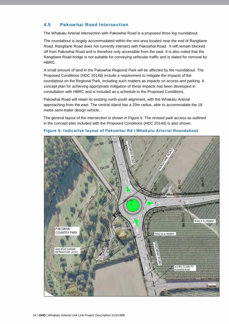
4.5 Pakowhai Road Intersection
The Whakatu Arterial intersection with Pakowhai Road is a proposed three leg roundabout.
The roundabout is largely accommodated within the rest area located near the end of Rangitane Road. Rangitane Road does not currently intersect with Pakowhai Road. It will remain blocked off from Pakowhai Road and is therefore only accessible from the east. It is also noted that the Rangitane Road bridge is not suitable for conveying vehicular traffic and is slated for removal by HBRC.
A small amount of land in the Pakowhai Regional Park will be affected by the roundabout. The Proposed Conditions (HDC 2014d) include a requirement to mitigate the impacts of the roundabout on the Regional Park, including such matters as impacts on access and parking. A concept plan for achieving appropriate mitigation of these impacts has been developed in consultation with HBRC and is included as a schedule to the Proposed Conditions.
Pakowhai Road will retain its existing north-south alignment, with the Whakatu Arterial approaching from the east. The central island has a 20m radius, able to accommodate the 18 metre semi-trailer design vehicle.
The general layout of the intersection is shown in Figure 6. The revised park access as outlined in the concept plan included with the Proposed Conditions (HDC 2014d) is also shown.
Figure 6: Indicative layout of Pakowhai Rd / Whakatu Arterial Roundabout

GHD | Report for Hastings District Council - Whakatu Arterial Link, 51/31468/ | 15
4.6 Local Road Intersections
4.6.1 Whakatu Road
There will be one local road intersection on the arterial and this will be with Whakatu Road taking the form of a roundabout intersection with a 13m radius central island.
Whakatu Road currently provides the only crossing of the Karamu Stream from the south via Ruahapia Road. This bridge crossing will be maintained, however Ruahapia Road will be closed off east of the railway crossing near Otene Road and at the Ruahapia Road / Pakowhai Road intersection. Refer to discussion on road closures in Section 4.9 below.
The bridge and south-western end of Whakatu Road is therefore intended to only be used for property access including the Apollo Pac industrial development east of the bridge.
Whakatu Road will be slightly re-aligned on the approaches to the roundabout to ensure sufficient entry deflection and approach angles.
The layout of the intersection is shown in Figure 7.
Figure 7 Whakatu Road Intersection
Whakatu Arterial
Whakatu Road

16 | GHD | Whakatu Arterial Link Link Project Description 51/31468/
4.7 Farndon Road Intersection
Works proposed at this intersection are not part of the WAL project, either as defined by the HPTS or as part of the notice of requirement or consents applications being lodged, and are not required for the efficient operation of the WAL. However, proposed improvements are outlined here because the EBD process included a specific recommendation that the safety of this intersection be improved as part of the new intersection of the WAL with Pakowhai Road. In response to this recommendation, a design is proposed in this document and it is understood that these improvement works will be undertaken by HDC as part of a safety upgrade.
Four options for the Farndon Road / Pakowhai Road intersection have been assessed, being:
1. Intersection becomes a three arm roundabout (40m internal diameter);
2. Right turn out of Farndon Road is prohibited, a channelised southbound merge is added. Left and Right turn into Farndon Rd remains unchanged;
3. Right turn out of Farndon Rd is prohibited, existing left turn out of Farndon is relocated to current right-turn lane and a solid median introduced to channelize movements on Pakowhai Rd; or
4. Combination of 2 and 3 above.
The roundabout option was not considered favourably as it would interrupt (slow down) through traffic along Pakowhai Road and could not meet site distance criteria due to the close proximity of the bridge and vertical grade issues.
Options 2, 3 and 4 all allow for uninterrupted flow from the new arterial road to the expressway, whilst providing for improved safety for access to and from Farndon Road.
Option 4 has ultimately been assessed as the option that best meets project objectives and the expectations of the EBD working group. This option utilises the existing left turn slip facility from Pakowhai Road onto Farndon Road.
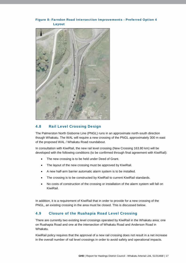
A design has been developed to fit within the existing road boundaries, preventing land requirement. This has required the inclusion of a retaining wall and guardrail that may require visual mitigation. Refer Figure 8 below:
GHD | Report for Hastings District Council - Whakatu Arterial Link, 51/31468/ | 17
Figure 8: Farndon Road Intersection Improvements - Preferred Option 4 Layout
4.8 Rail Level Crossing Design
The Palmerston North Gisborne Line (PNGL) runs in an approximate north-south direction though Whakatu. The WAL will require a new crossing of the PNGL approximately 300 m east of the proposed WAL / Whakatu Road roundabout.
In consultation with KiwiRail, the new rail level crossing (New Crossing 163.80 km) will be developed with the following conditions (to be confirmed through final agreement with KiwiRail):
• The new crossing is to be held under Deed of Grant.
• The layout of the new crossing must be approved by KiwiRail.
• A new half-arm barrier automatic alarm system is to be installed.
• The crossing is to be constructed by KiwiRail to current KiwiRail standards.
• No costs of construction of the crossing or installation of the alarm system will fall on KiwiRail.
In addition, it is a requirement of KiwiRail that in order to provide for a new crossing of the PNGL, an existing crossing in the area must be closed. This is discussed below.
4.9 Closure of the Ruahapia Road Level Crossing
There are currently two existing level crossings operated by KiwiRail in the Whakatu area; one on Ruahapia Road and one at the intersection of Whakatu Road and Anderson Road in Whakatu.
KiwiRail policy requires that the approval of a new rail crossing does not result in a net increase in the overall number of rail level crossings in order to avoid safety and operational impacts.

18 | GHD | Whakatu Arterial Link Link Project Description 51/31468/
In order to achieve this result, either the Ruahapia Road level crossing or the Whakatu Road level crossing must be closed.
The closure of the Ruahapia Road level crossing has been considered as the preferred option for the following reasons:
• Discourages the use of Ruahapia Road, reducing traffic and improving safety for the community.
• Removes the conflict at the existing level crossing that currently has a substandard road alignment from the southeast.
• The Whakatu Road / Anderson Road rail crossing is required for internal traffic movements within Whakatu; its closure would significantly impede connections from Whakatu to the WAL.
• Some local traffic, i.e. Ruahapia Road residents that would traditionally use the Otene/Ruahapia/Whakatu Roads to access Whakatu and beyond, would need to divert and increase the travelled distance to reach their destination. However, the majority of traffic will travel shorter distances with the WAL in place.
In addition to closing the Ruahapia Road rail crossing, Ruahapia Road will also be closed at the intersection with Pakowhai Road. This is a historically unsafe intersection, and will no longer be required. Through traffic will use the WAL and access to existing properties on Ruahapia Road north of the rail crossing will be provided via the existing Whakatu Road Bridge.
HDC will need to initiate a formal road closure process under the provisions of the Local Government Act or Public Works Act in order to give effect to these closures.
The consultation and options analysis process undertaken in considering the closure of the Ruahapia Road rail crossing is outlined in more detail in the Alternatives Assessment Report (EMS 2014b)
4.10 Cycleways
The WAL will cross the existing Hastings-Clive cycleway in Whakatu. Access across the WAL is proposed via an underpass constructed on the line of the existing limesand path. The underpass will be constructed to maximise sight lines and lighting.
Pedestrian and cycle movements are catered for in the footpath and cycle way on the WAL bridge. The WAL road shoulders provide space for cyclists along the remainder of the route however it is anticipated that these road users will use Ruahapia Road and Whakatu Road rather than the WAL.
It is understood that HDC has plans to promote the use of Ruahapia Road for cycle use and will provide more off road connections to the adjacent network.
4.11 Karamu Stream Bridge Design The WAL crosses the Karamu Stream once near the northern end of the project area. The design of this crossing is a key element, given inherent engineering, environmental and cultural considerations.
4.11.1 Karamu Stream Management Approach
Bridge works have been designed with guidance from the Cultural Impact Assessment (Ipurangi Developments 2014) and with input from HBRC.
GHD | Report for Hastings District Council - Whakatu Arterial Link, 51/31468/ | 19
The Cultural Impacts Assessment includes the following recommendation regarding bridge design:
Recommendation 5: The proposed bridge is designed and constructed in a way that does not obstruct the flow/ mauri of the Karamu stream.
The HBRC have various works proposed to maintain adequate flow and reduce the risk of flooding of the Karamu Stream. The stream has issues with weed collecting on any obstructions within the waterway which increase the risk of flooding. Works currently proposed by HBRC for improvements in this area include:
• Removal of the Rangitane Road footbridge and floodgates;
• A long term plan to work with HDC to remove the main trunk sewer mains that cross the stream at Otene Road; and
• Construction of a widened flood channel from the Whakatu Road bridge to the Rangitane pedestrian bridge.
Comments from HBRC in relation to the WAL bridge include:
• Piers must be of a suitable design profile that prevents debris, particularly weeds, from catching on the upstream side during flooding events;
• HBRC will consider abutments intruding slightly beyond the channel profile; and
• The Q100 flows are estimated at 135 cubic metres per second.
These considerations have informed a bridge design that avoids disturbance of the wet stream bed.
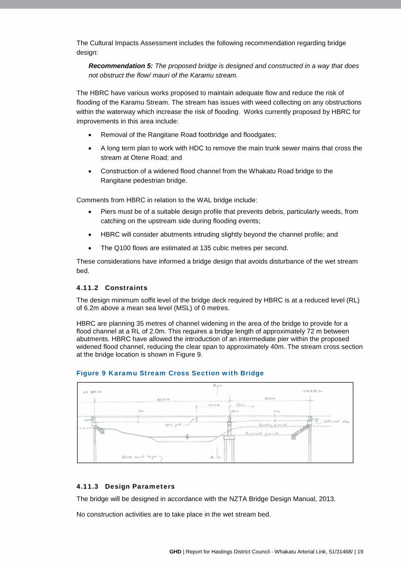
4.11.2 Constraints
The design minimum soffit level of the bridge deck required by HBRC is at a reduced level (RL) of 6.2m above a mean sea level (MSL) of 0 metres. HBRC are planning 35 metres of channel widening in the area of the bridge to provide for a flood channel at a RL of 2.0m. This requires a bridge length of approximately 72 m between abutments. HBRC have allowed the introduction of an intermediate pier within the proposed widened flood channel, reducing the clear span to approximately 40m. The stream cross section at the bridge location is shown in Figure 9. Figure 9 Karamu Stream Cross Section with Bridge
4.11.3 Design Parameters
The bridge will be designed in accordance with the NZTA Bridge Design Manual, 2013. No construction activities are to take place in the wet stream bed.
20 | GHD | Whakatu Arterial Link Link Project Description 51/31468/
4.11.4 Design Loadings
The bridge will be designed for full HN-HO-72, with full HPMV capabilities. Seismic loading will be allowed for in the design.
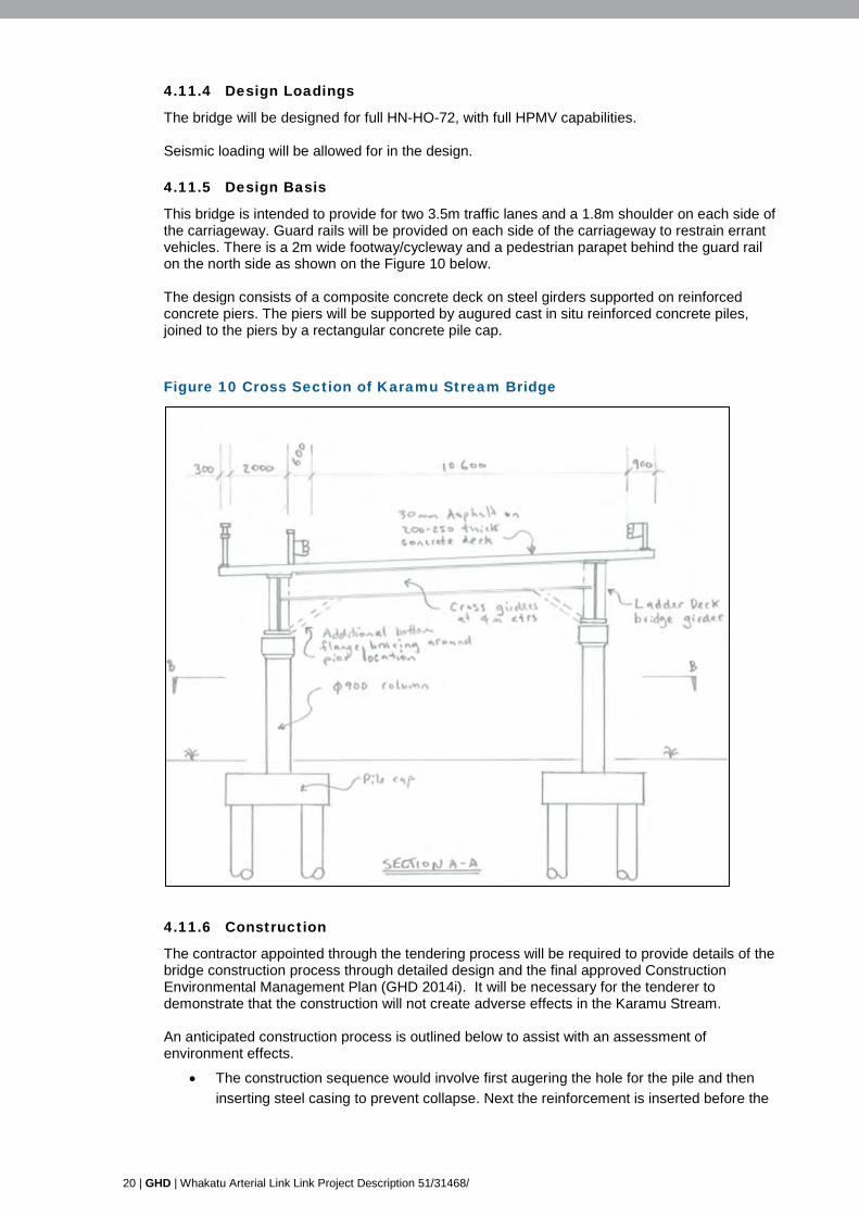
4.11.5 Design Basis
This bridge is intended to provide for two 3.5m traffic lanes and a 1.8m shoulder on each side of the carriageway. Guard rails will be provided on each side of the carriageway to restrain errant vehicles. There is a 2m wide footway/cycleway and a pedestrian parapet behind the guard rail on the north side as shown on the Figure 10 below. The design consists of a composite concrete deck on steel girders supported on reinforced concrete piers. The piers will be supported by augured cast in situ reinforced concrete piles, joined to the piers by a rectangular concrete pile cap. Figure 10 Cross Section of Karamu Stream Bridge
4.11.6 Construction
The contractor appointed through the tendering process will be required to provide details of the bridge construction process through detailed design and the final approved Construction Environmental Management Plan (GHD 2014i). It will be necessary for the tenderer to demonstrate that the construction will not create adverse effects in the Karamu Stream. An anticipated construction process is outlined below to assist with an assessment of environment effects.
• The construction sequence would involve first augering the hole for the pile and then inserting steel casing to prevent collapse. Next the reinforcement is inserted before the

GHD | Report for Hastings District Council - Whakatu Arterial Link, 51/31468/ | 21
concrete is poured. Whilst the concrete is being poured the steel casing is extracted. All piles are located outside of the wet stream bed.
• After the piles are completed the concrete pile caps are then cast in situ forming a platform on which to construct the concrete piers. These will be cast in situ using temporary shuttering and temporary supports where necessary. Once the concrete has gained sufficient strength the shuttering and supports will be removed.
• The steel girders for the bridge will be craned into place from cranes at suitable locations (within dry land, i.e. no interference with the running water). Whilst fabrication of the girders will be off site some assembly of components prior to lifting into place may be required on site. After the girders are in place the concrete sections forming the deck will be craned in. Depending on the final design a top slab may be cast in situ on top of the concrete panels.
• Finally water proofing followed by road pavement materials and surfacing together with parapets and guard railing will be installed.
4.11.7 Design Basis
The basis of the design is to allow construction of the bridge without interfering with the stream channel. The use of precast concrete or steel girders has been identified as a solution that avoids the need for temporary works in the stream bed and less risk of pollution incidents.
4.12 Stormwater Design
4.12.1 Stormwater Configuration
A Stormwater Management Plan (GHD 2014g) has been developed and is provided with the RMA application documentation. It outlines the proposed approach to stormwater management during the operational phase of the WAL, including specifying minimum design and operation requirements. A supporting Erosion and Sediment Control Plan (GHD 2014h) is also provided to manage the effects of surface water runoff during soil disturbance activities associated with construction.
The management plans present a low impact design that utilise swale drains on both sides of the road to collect and convey stormwater runoff. The swales discharge into the existing roadside drains at the tie-ins with the existing road network and into the Karamu Stream where the WAL is in close proximity to the stream.
The swales are designed to allow for infiltration to reduce peak discharge flows and to provide stormwater treatment.
The proposed swale cross section was derived using the following parameters:
• Maximum side slopes of 1:4 (H:V), which is within the 1:3 maximum as recommended by NZS 4404:2010;
• 0.6 m minimum base width to create a large surface area to increase the extent of infiltration and filtration;
• Minimum depth of 0.2 m. Depths less than this are generally not recommended as a minor obstruction has the potential to completely block the swale.
These considerations resulted in a minimum cross sectional profile as illustrated below (the sketch is not to scale). The swale will be deeper and therefore wider where required to:
• Provide sufficient flow capacity; or
• Due to the longitudinal grade in relation to the surrounding ground levels.

22 | GHD | Whakatu Arterial Link Link Project Description 51/31468/
Figure 11 Minimum Swale Cross Section
4.12.2 Hydrology and Hydraulic Analysis
The extent of stormwater runoff for each swale was estimated using the rational method as outlined in The New Zealand Building Code Clause E1/VM1 for a 10-year design storm return period. The area’s rainfall intensity was determined using NIWA’s High Intensity Rainfall Design System (HIRDS). A 10 minute time of concentration was estimated for the proposed swales.
The following runoff coefficients were used in the calculations:
• 0.3 for grass covered areas;
• 0.9 for the sealed carriageway.
The swales were then sized to convey this flow using Mannings equation. A longitudinal grade of 0.2 % was assumed for all swales. This is the minimum grade recommend and due to the flat topography it is likely that most of the swales will be at this minimum grade.
4.12.3 Culverts / Pipes
The culverts will be sized so that they do not cause flooding of the upstream swales. It is proposed that culverts crossing the roads will generally have NZTA approved traversable wing walls (complete with grate) on either end.
Where the topography allows, the inlet to the discharge pipes under the Karamu Stream stopbank will be via a sump type configuration using scruffy domes and appropriately sized manholes. The top of the manholes will be at the invert of swale. Where the topography is such that this design is not achievable, a similar inlet structure to the road culverts will be used. Both of these systems have grates which are selected to prevent gross pollutants entering the Karamu Stream.
The outlets into the Karamu stream will be designed to minimise the impact to the stream bed and to reduce the risk of scouring. This will most likely consist of a normal concrete headwall with a riprap type system if high flow velocities are likely. To maintain flood protection, WaStop valves (or similar type check valves) will be required where the pipes pass under the stopbank.
There will be 7 outlets into the Karamu Stream.
4.13 Street Lighting Design
An initial street lighting design has been undertaken covering all intersections along the proposed alignment as well as the mid-block section between the Whakatu Road intersection, and the rail level crossing.
The required lighting level has been evaluated with a copy of the lighting design sub-category evaluation provided in Appendix B. The rating value of 110 is covered by both the V2 and V3

GHD | Report for Hastings District Council - Whakatu Arterial Link, 51/31468/ | 23
categories. V2 was agreed given that the expected increases in traffic in the future, as well as other demands on drivers including the rail level crossing that will eventually lift the required design level.
The initial design incorporates the Kaos light fitting. HDC are progressively replacing old fittings with the Kaos fittings. The Kaos fittings are acknowledged as a high calibre fitting with very limited light spill and glare technology and efficient light projection. The bulbs are still high pressure sodium; however there is new LED technology that is progressively becoming more mainstream, which could be considered. Potential benefits include lower power consumption and lower replacement frequency.
All new cabling for the street lights will be underground. Intersection lighting will generally be on individual circuits each requiring a transformer box that will draw electrical feed from the nearest source. The transformers will likely be stand alone, and mounted at ground level close by in a safe location.
All lighting has been designed to be mounted on the outside of the intersection on single new 12m high light columns, i.e. there are currently no lighting columns proposed for the internal roundabout islands. This makes access straight forward reducing future maintenance costs.
Table 4 provides a summary of the design.
Table 4: Street Lighting Design Summary
Location Lighting Design Summary
Pakowhai Road Roundabout 17 new lights and 800m new cabling
Whakatu Road Roundabout 13 new lights and 650m new cabling
Napier Road SH2 Roundabout 30 new lights and 2200m new cabling
5. Project Construction 5.1 Construction Environmental Management Plan
All construction works are required to be carried out in accordance with a certified Construction Environmental Management Plan (CEMP) (refer Proposed Conditions HDC 2014d).
A draft CEMP (GHD 2014i) has been developed and is included with the RMA application documents. The CEMP is required to be updated by the contractor appointed through the tendering process in accordance with the proposed construction methodology. The updated CEMP must be certified by HDC and HBRC prior to construction commencing. The CEMP includes objectives and specific performance criteria that are required to be met through the construction phase such that environmental requirements are met.
5.2 Project Construction Schedule
This section is intended to provide high level information on the anticipated construction of the project to provide sufficient detail to assess the potential environmental effects and identify any necessary measures to avoid, remedy or mitigate those effects.
The majority of the WAL will be constructed off line (i.e. not alongside or on top of an existing road) through the industrial and horticultural land described in Section 3.

24 | GHD | Whakatu Arterial Link Link Project Description 51/31468/
The critical elements in terms of managing effects on road users will therefore be the intersections with existing roads, where the staging of construction will need to be carefully considered in order to maintain traffic flow and minimise adverse effects on existing road users.
The other major considerations are maintaining property access, particularly to the industrial properties located around Whakatu Road, and minimising impacts on activities such as orcharding and pack house activities that are more sensitive to potential construction impacts during certain times of the year.
Construction of the project is expected to take around 18 months (or two construction seasons) with works carried out concurrently at various locations to optimise the construction process while seeking to minimise disruption to existing road users, land owners and the local community. The construction period is a guide at this stage. As the majority of the project will be carried out off line there is flexibility around the scheduling of work with opportunity to condense or extend this construction period.
It is envisaged that the construction of the main alignment can be undertaken concurrently with the key aspects described below and not be opened to traffic until the intersections are completed.
The key aspects of the construction are considered to be:
• SH2 / Napier Road roundabout;
• Karamu Stream bridge;
• Pakowhai Road roundabout;
• Whakatu Road Roundabout;
• Railway crossing;
• Property access particularly at Whakatu Road (Apollo Pac).
The contractor appointed through the tendering process will be required to finalise the CEMP which will include an outline construction programme identifying and sequencing all the key parts of the Contract Works. This baseline programme shall clearly indicate which parts of the works are to be under construction at any time and the total planned duration of each part. The total planned duration shall include all reinstatement works, including sealing, where this is required. This programme will be required to be updated on a regular basis during construction to gauge progress against the baseline programme.
The specific comprehensive construction methodology will be identified by the contractor in the final CEMP. The contractor will specify how the contract works will be delivered on time and to the standard and requirements specified in the Contract Documents. The methodology must clearly state how the work is to be carried out with minimum disruption to the users of the businesses in the project area and the public and indicate how they will ensure that the site is maintained in a safe and useable condition during the period of the work and any close down periods. This methodology will also demonstrate how the contractor will meet the environmental standards that may be identified in the environmental assessment and consenting process.
5.3 Construction overview
Enabling works
Early works will include the relocation or protection of services such as electricity and telecommunication services and privately owned assets such as affected infrastructure in the orchard blocks (refer Productive Land Use Impact Assessment, AgFirst, 2014). Throughout

GHD | Report for Hastings District Council - Whakatu Arterial Link, 51/31468/ | 25
property negotiations the early planting of shelterbelts could also be agreed and could form part of the enabling works.
Construction of site access roads particularly for construction of the bridge from the west and east will also be completed, together with the construction of the sedimentation ponds in accordance with the Erosion and Sediment Control Plan (GHD 2014h). The construction access roads will be located over the general alignment to minimise the effects on private land owners during construction, and the areas set aside for sedimentation ponds are included within the land proposed for designation to provide certainty for the construction process and landowners.
Main Alignment
As described above the construction scheduling of the main alignment will be relatively flexible due to it generally being undertaken off line. It is however envisaged that these works will be carried out concurrently with the major intersections.
A consideration for the construction of the main alignment is maintaining property access, particularly to the Apollo Pac Ltd industrial site whose existing access is located on the alignment of the arterial road. Construction methods in relation to property access are discussed further in Section 5.5.
Another key consideration is the impact on orchard blocks and processing facilities during critical harvest periods (refer Productive Land Use Impact Assessment, AgFirst, 2014).Construction activities will be programmed to avoid impacts on these properties during critical times, with the specific approach confirmed in the final CEMP and informed by landowner consultation.
The bridge construction will be scheduled during the initial phases of the construction period and is expected to take between 9 to 12 months. Works on the bridge could begin following the construction of the temporary access roads.
As discussed in Section 4.1.3, the WAL will source fill by undertaking planned flood channel widening on behalf of HBRC in the vicinity of the bridge. The fill resulting from these works is likely to be used for the construction of embankment fill on the project. No construction is proposed in the stream bed. The contractor will need to provide adequate protection on and around the bridge works to ensure no materials fall into the stream and pollute the water.
There is opportunity to locate a site compound in the area north of Whakatu Road for use during construction of the project.
Water quality effects during construction will be managed in accordance with the Erosion and Sediment Control Plan (GHD 2014h)).
Traffic Management
A Traffic Management Plan (GHD 2014j) has been prepared and included with the RMA application documents.
As the majority of construction work will take place offline (i.e. not connected with existing public roads) traffic impacts will be kept to a minimum. The three major intersections of the WAL are the most complex in terms of traffic management, and construction should not be programmed such that vehicle delays occur concurrently.
By careful staging of the works local access to affected properties can be maintained and detours kept to a minimum.
After award of the contract the contractor will be required to prepare SSTMPs for each stage and section of the works. These will form part of the Traffic Management Plan and will cover in

26 | GHD | Whakatu Arterial Link Link Project Description 51/31468/
detail items such as the level of traffic signs, lane widths, measures for pedestrians across the works and detour routes. The contractor will not be able to put any traffic management measures in place without the prior approval of either Hastings District Council or NZ Transport Agency as the RCA appropriate for the section of road affected.
5.4 Construction workforce
The construction workforce will be appointed by the contractor. The contractor appointed for the WAL will be required to nominate the following key personnel:
• Contractor’s Representative
• Contract Manager
• Senior field supervisor(s)
• Quality Manager
• Environmental Manager
• Health & Safety Manager
• STMS Staff.
5.5 Hours of construction work
Construction will typically be undertaken between the hours of 7:00am and 6:00pm. At the three main intersections major works will be undertaken outside of peak periods to minimise traffic delay whenever possible. Hours of operation will be specified in the CEMP and SSTMPs for acceptance by the HDC.
KiwiRail has indicated that the construction of the new railway crossing will be undertaken by KiwiRail, which will ensure that any impacts on the rail network can be managed directly and avoided.
5.6 Property access
During construction, access will be affected to some properties. The impacts are expected to be caused by one of the following:
• Worksites blocking direct access or delaying access to properties;
• Access being within a road closure; or
• Property access being on a nominated detour route.
SSTMPs will contain details identifying the proposed mitigation measures for all relevant impacts on the properties for acceptance by HDC. Consultation with the owners and occupiers of all affected properties will be undertaken prior to the SSTMPs being submitted to HDC.
One of the most challenging access issues exists at the Apollo Pac site which is located off Whakatu Road in the vicinity of the new Arterial alignment. Access to this busy industrial site will be directly affected by the new road. To ensure no business disruption, the section of WAL through this site will only be constructed once an alternative access is established.
Another key issue is to avoid impacts during key harvest periods (AgFirst 2014).
The SSTMPs will provide specific provisions for access to affected properties. Consultation will also be undertaken through the development of these plans to ensure the residents/business have appropriate access to meet their needs, for example with respect to heavy vehicle provisions. It is expected that all access issues can be effectively managed through the development and implementation of SSTMPs.

GHD | Report for Hastings District Council - Whakatu Arterial Link, 51/31468/ | 27
5.7 Temporary facilities
5.7.1 Site Offices and Compound
An area to the north-west of Whakatu Road has been identified as a suitable location for the contractor’s compound and site office. It is a decision of the successful contractor on where to site their site offices and site compound and this will be confirmed in the final CEMP. The contractor may negotiate the use of private land with the land owner during the tender process.
Services such as electricity and water to the site compound will be required and arranged by the contractor.
5.7.2 Construction laydown and stock pile areas
In addition to the main site compound and offices the Contractor may need to allow for laydown areas for construction plant and materials at the various works that may be ongoing at any one time. The number and locations of these will not be confirmed until a Contractor has been appointed.
5.7.3 Staff amenities
Staff amenities are to be provided at each work site on the project. Potable water for domestic use by the construction workforce will be transported to the construction sites. Port-a-loos will be used whereby sewage will be transported off-site and disposed of in a lawful manner by a contractor
5.8 National Environmental Standards on Air Quality
The National Environmental Standards (NES) relating to air quality during construction are expected to be met by the contractor. The construction activities are not expected to lead to adverse air pollution that exceeds the levels stipulated in the standards.
Dust suppression is to be addressed through a Dust Control Management Plan that will be prepared in conjunction with the CEMP. In particular, the effects of dust on fruit production during critical harvest and packaging periods must be mitigated.
5.9 Earthworks
Construction of the WAL will result in the removal of approximately 26,200m3 of topsoil and approximately 28,880m3 of cut to waste. All excavated material is to be disposed of offsite in accordance with any relevant District Plan requirements and any subsequent earthworks’ consents granted to the contractor.
In order to construct the WAL there will be an overall importation of soil for embankment construction. It is estimated that 50,000m3 of fill will be able to be sourced through the completion of available HBRC’s flood alleviation works in the Karamu Stream. The remainder of the structural fill is likely to be sourced locally within a reasonable area.
5.10 Potential impacts from construction
The main impacts from construction activities are expected to be:
• Dust
• Vibration
• Noise
• Heavy Commercial Vehicles (HCVs)

28 | GHD | Whakatu Arterial Link Link Project Description 51/31468/
• Erosion and deposition of sediment
• Water Quality
• Pollution/Accidental Spillages.
These measures are discussed below.
5.10.1 Dust/Air Quality
For the construction phase potential sources of airborne dust include:
• wind-blown dust from exposed surfaces;
• wind-blown dust from stockpiles of dusty materials; and
• dust caused by vehicle movements on sealed or unsealed roads
In relation to potential for odour impact potential sources are from:
• Introduced contaminated materials; and
• Insitu soils with high organic content that have potential to decompose on contact with air.
As part of the CEMP, the successful contractor is required to provide a Dust Control Management Plan (DCMP) for certification prior to construction commencing. The DCMP shall include, but need not be limited to, the following:
a) Description of the construction works and potential sources of dust;
b) Periods of time when emissions of dust might arise from construction activities;
c) Identification of any sensitive land uses that may potentially be adversely affected by emissions of dust from construction activities;
d) Measures for minimising and managing dust emissions;
e) Methods for monitoring dust during construction, including visual inspections of dust sources and dust generating activities, visual inspections of management measures, checking weather forecasts and observing weather conditions;
f) Methods for undertaking and reporting on the results of daily inspections of construction activities that might give rise to dust; and
g) Methods for receiving and responding to complaints about dust emissions.
The following measures are proposed to be incorporated in the DCMP to ensure that any short-term actual or potential adverse effects on from dust generation can be avoided, remedied or mitigated:
• Initial vegetation removal should be limited to that necessary for construction purposes and carried out in discrete sections to avoid large sections of exposed earth;
• Vehicles running over exposed areas, including those that are in the process of becoming formed embankments have the potential to remobilise dust. In addition to dampening down with water, construction site speed limits should be implemented. The draft NZTA erosion and sediment control document (NZTA 2010) contains information about dust control (NZTA 2010, section 8.3.6);
• The number of stockpile areas should be minimised and provided with covers and / or shielded to prevent wind mobilising dust from the pile. Stockpiles may require water spraying and the loading and accesses should be hard paved and swept / damped

GHD | Report for Hastings District Council - Whakatu Arterial Link, 51/31468/ | 29
down on a regular basis. Stockpile areas should be reinstated following the conclusion of construction in accordance with the landscape philosophy statement; and
• Areas affected by construction should be re-vegetated as soon as each construction section is completed in accordance with the landscape philosophy statement. The draft NZTA erosion and sediment control document (NZTA 2010) contains information about soil stabilisation thorough topsoiling and grass seeding (Section 8.3.1), hydroseeding (8.3.2), mulching (8.3.3) and turfing (8.3.4).
It is considered that adoption of these measures will ensure that any actual or potential short-term effects on amenity from dust generation will be minor, and that no significant long-term effects on amenity from dust generation will arise.
5.10.2 Vibration
The construction will be in close proximity to industrial sites, some of which involve sensitive processing equipment. ENZA in particular have highlighted concerns about vibration on their pack houses and operations therein. This has been investigated in the Noise Assessment (Hegley 2014).
A Construction Noise and Vibration Management Plan shall be prepared in conjunction with the CEMP (refer Proposed Conditions HDC 2014d) to manage these effects.
5.10.3 Noise
The requirements for construction noise are specified in NZS6803:1999: Acoustics-Construction Noise which sets maximum noise levels. The Noise Assessment (Hegley 2014) outlines the potential effects of construction (and traffic) noise associated with the WAL.
Plant commonly used for construction including motor scrapers, excavators, graders, rollers and pavers have been used to predict noise levels at each of the PPFs used for the Operational Noise assessment.
Typically, successful mitigation options include:
• Use smaller, quieter plant;
• Limit the use of some noisier equipment to the most exposed properties; and
• Use of screening.
The assessment of noise from typical construction activities has shown that some mitigation to the noisier plant may be necessary when working close to the most exposed properties.
There are practicable options for achieving the reductions required in order to meet the requirements of NZS6803:1999. However, due to the large number of variables that affect construction noise, the only practicable method of managing these effects is by the preparation of a Construction Noise and Vibration Management Plan by the successful contractor that is to be submitted for approval by HDC.
5.10.4 Impact of Construction HCVs on Roading Network
During periods of earthworks, particularly construction of the road embankment, there will be significant numbers of HCVs using the roading network. The frequency and duration of these movements will be dependent on the contractor’s programming of the works. It is expected that 50,000 cubic metres of soil excavated as part of the flood defence works may be available thus reducing the distance travelled and numbers of construction HCVs travelling along the roading network.
30 | GHD | Whakatu Arterial Link Link Project Description 51/31468/
The routes and frequency of HCV movements particularly during earthworks will need to be addressed by the contractor in the CEMP.
5.10.5 Sediment and Erosion Control
The removal of ground cover, earthworks and associated activities during construction may lead to the generation of sediment laden runoff which may affect water quality and affect adjacent agricultural areas. Appropriate mitigation measures are required to ensure that the effects of any sediment discharges are only minor.
A Sediment and Erosion Control Plan (GHD 2014h) has been prepared and is included with the RMA application documentation.
The Contractor will be required to comply with the requirements of the Sediment and Erosion Control Plan.
It is expected that the contractor will effectively programme the works so as to minimise the amount of un-stabilised ground exposed at any one time. The erosion and sedimentation measures are to be appropriately maintained throughout the construction works until the ground has been stabilised to ensure they function effectively.
5.10.6 Pollution and Accidental Spillages
The contractor is expected to provide measures to prevent accidental spillages during construction activities, particularly from oil and diesel storage tanks, entering watercourses. The approach taken will be included in the Contractor’s final CEMP however it is noted that HBRC have developed a generic spill management plan. This is included as Appendix C. The final CEMP will incorporate the relevant provisions of this plan to ensure that appropriate management approaches are in place to address any spillages.
6. Operation and Maintenance 6.1 Operation
This section provides a summary of the maintenance issues and further operational features of the arterial road that have not been covered in the preceding sections of this report.
6.2 Maintenance
The long term maintenance requirements of the completed works are:
• Traffic services - cleaning and repairs to road signs and lights, renewal of road markings;
• Railway crossing – inspection and testing of signalling and barrier equipment;
• Road pavement - resealing of road surface (between years 7 and 10) and rehabilitation of road pavement (between years 14 and 20) in future years;
• Guard Rails - cleaning, inspection and repairs to guard rails including terminal ends;
• Bridge Structures - General and Principal Inspections, repainting and graffiti removal;
• Drainage - catchpit, swale, culvert and drainage channel clearing; and
• Landscape - mowing of berms, trimming and replacing plantings.
The maintenance requirements will be dependent on the final construction design and will be detailed in the Asset Owner’s Manual to be produced on completion of the project.
GHD | Report for Hastings District Council - Whakatu Arterial Link, 51/31468/ | 31
The responsibility of the new arterial road will lie with Hastings District Council as the Road Controlling Authority for the local road network whilst SH2 and the Pilcher Road roundabout (excepting the local road approaches) will be State Highway with NZTA as the RCA. The exact maintenance boundaries are to be determined.
With the exception of the level crossing barriers, associated signalling and track work which are the responsibility of KiwiRail, the above items will be the responsibility of the RCAs.
6.3 Potential impacts from operation and maintenance
Following construction, the ongoing operation and use of the Whakatu Arterial has the potential to cause environmental, social and economic impacts. The following potential impacts have been considered:
• Traffic and economics
• Productive land use
• Noise
• Vibration
• Landscape, natural character and amenity
• Natural hazards
• Stormwater and surface water runoff
• Ecology and water quality
• Cultural heritage and archaeology
• Social-cultural effects.
Brief outlines of these issues and their potential effects and the steps taken to avoid, remedy or mitigate them are outlined below. This information is intended to support and inform a full assessment of environmental effects as reported in the AEE technical assessment reports provided in Part C of the RMA application documentation.
6.3.1 Traffic and Economics
Crash Rates
The WAL is designed to current safety standards and is expected to result in a reduction in crash levels on the wider network as traffic diverts on to the new road. The existing five year crash records from the CAS database together with the crash rates and crash prediction models in Appendix A6 of the NZTA’s Economic Evaluation Manual (EEM) have been used to determine the potential changes in crash rates over the study area as a result of the new arterial road.
Output from a refined HPTS traffic model has been used to analyse annual daily traffic (ADT) flow data and highlight key links and intersections that experience the most significant change in traffic volumes in the 2009, 2026 and 2046 road networks. In order to focus on the major accident costs and savings, those links that experience an approximate 10% change in volumes have been captured in the assessment. A minimum ADT threshold of 500 vpd was also applied to the selection criteria to put a sensible limit on the number of links and intersections analysed.
Overall, 22 intersections and 34 mid-block sections were analysed totalling approximately 60 km of road. The level railway crossings at Elwood Road, Ruahapia Road and Whakatu Road were also included.
The results of the analysis are summarised in the table below:

32 | GHD | Whakatu Arterial Link Link Project Description 51/31468/
Table 5 Accident Cost Summary
Accident Cost
Do Minimum Project
2009 2026 2046 2009 2026 2046
Mid-Block $7.11M $8.96M $10.26M $6.35.M $8.34M $9.72M
Intersections $2.66M $2.92M $3.15M $1.77M $2.01M $2.17M
Total $9.77M $11.88M $13.41M $8.12M $10.35M $11.89M
Mid-block crash savings mainly accrue from a significant amount of traffic transferring from local roads onto the safer arterial. The introduction of safer intersection controls (i.e. provision of roundabouts) for traffic travelling to and from the Whakatu industrial area also results in positive safety benefits.
Following the opening of the WAL crash records will need to be periodically reviewed to ensure the crash benefits are being realised. Should the post opening review of crash records indicate that the crash benefits are not being achieved, or if there are any safety issues with the new road, these can then be identified and consideration given to appropriate remedial measures.
Traffic Flows
From the HPTS traffic model the predicted changes in traffic flows from the existing network, (Do Minimum), to the proposed network with the new arterial road in 2026 have been determined and are shown in Table 6 below.
Table 6 Do Minimum and Project 2026 Annual Daily Traffic Flows
Road and location Do Min Project Change
Whakatu Arterial (southern end) - 9,750 +9,750
Whakatu Arterial (northern end) - 16,750 +16,750
Ruahapia Road (southern end) 3,000 500 -2,500
Ruahapia Road (northern end) 10,500 - -10,500
Elwood Road (southern end) 6,750 3,000 -3,750
Elwood Road (northern end) 5,500 4,000 -1,500
Otene Road 2,250 1,000 -1,250
Anderson Road 10,500 5,250 -5,250
Railway Road (through Whakatu) 3,000 2,000 -1,000
Pakowhai Road (north of Farndon Road) 9,000 10,750 +1,750
Pakowhai Road (south of Whakatu Arterial) 13,000 15,750 +2,750
Karamu Road (south of Whakatu Arterial) 18,750 17,500 -1,250
SH2 (north of Whakatu Arterial) 16,500 12,750 -3,750
SH2 (north of Clive) 16,250 15,500 -750
Napier Road (south of SH2) 4,000 6,000 +2,000
St Georges Road 5,500 3,750 -1,750
Note: Values rounded to nearest 250 vehicles.

GHD | Report for Hastings District Council - Whakatu Arterial Link, 51/31468/ | 33
The network effects are similar to that reported in the HPTS Project Feasibility Report. Flows in local areas are redistributed from the adjacent Elwood Road, Otene Road and Ruahapia Road routes.
A reduction in traffic flows through the Whakatu settlement on Anderson and Railway Roads together with a reduction of traffic using the SH2 coastal route are expected however more traffic will use Pakowhai Road to reach the Expressway. There will also be an increase in traffic along Napier Road from Havelock North however this is balanced by a reduction in traffic using the St Georges Road route to Havelock North.
Periodic traffic counts and surveys can be undertaken to determine the actual impact on the roading network.
Railway Level Crossing
An economic evaluation was undertaken of the effects of the level crossing on the operation of the arterial road in accordance with the NZTA’s Economic Evaluation Manual. The level of rail traffic fluctuates however the calculations are based on a mean service of 9 trains a day with one passing in each peak hour as a worst case scenario.
The increase in journey times and increase in vehicle operating times for the percentage of vehicles held or delayed at the crossing was calculated. Using the EEM crash models the additional crash costs inherent with this type of level crossing were also determined. The net present value of these costs amounts to $1.4M over a 30 year period.
However the removal of the Ruahapia Road crossing which has substandard horizontal and vertical alignment on both approaches will result in a reduction in crashes. This saving is taken into account in the economic evaluation.
6.3.2 Productive Land Use
A key driver through the EBD process was to reduce impacts on productive land, and route selection has taken this into consideration. However, the project will result in the loss of some land from productive use. It is noted that the remaining agricultural land alongside the new road is expected to remain in agricultural use, except for a small area where severance effects have made this unfeasible (refer Productive Land Use Impact Assessment, AgFirst 2014). The total area of land lost due to the road corridor and severance is approximately 20 ha.
There is potential reverse sensitivity effects associated with crop spraying and road users. The proposed conditions (HDC 2014d) include a requirement to provide shelterbelt planting or similar measures to address these effects, if requested by landowners.
The alignment runs through existing shelterbelts that will need to be partly removed for the road corridor. Any replacement or additional planting will need to be outside of the clear zone of the arterial road.
6.3.3 Noise
Key properties that will be impacted by noise are:
• The Haley property, where the WAL is within 15m of the residence;
• The Omahuri Orchards Property, where the WAL is within 60m of the residence;
• Pt Lot 1 DP 14513 Ward property, where the WAL passes within 30m of the residence; and
• The Dillion property, where the WAL is elevated and within 140m of the residence.
The cost estimate for the project has made some allowance for noise mitigation measures.
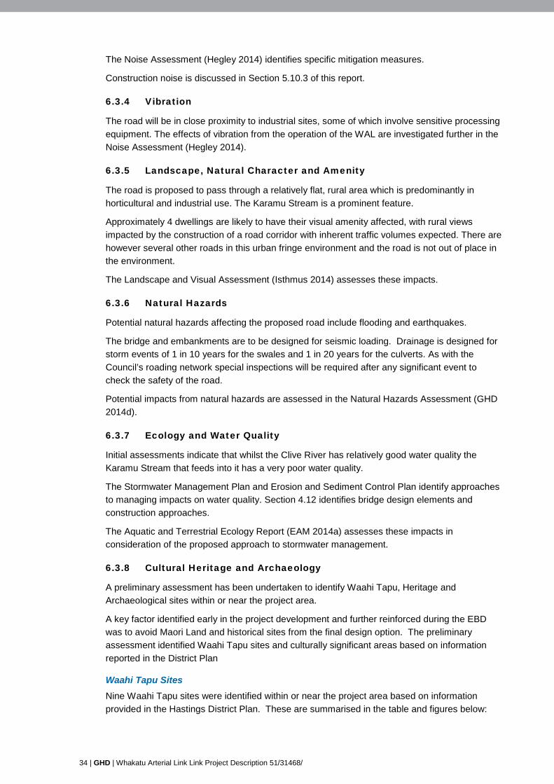
34 | GHD | Whakatu Arterial Link Link Project Description 51/31468/
The Noise Assessment (Hegley 2014) identifies specific mitigation measures.
Construction noise is discussed in Section 5.10.3 of this report.
6.3.4 Vibration
The road will be in close proximity to industrial sites, some of which involve sensitive processing equipment. The effects of vibration from the operation of the WAL are investigated further in the Noise Assessment (Hegley 2014).
6.3.5 Landscape, Natural Character and Amenity
The road is proposed to pass through a relatively flat, rural area which is predominantly in horticultural and industrial use. The Karamu Stream is a prominent feature.
Approximately 4 dwellings are likely to have their visual amenity affected, with rural views impacted by the construction of a road corridor with inherent traffic volumes expected. There are however several other roads in this urban fringe environment and the road is not out of place in the environment.
The Landscape and Visual Assessment (Isthmus 2014) assesses these impacts.
6.3.6 Natural Hazards
Potential natural hazards affecting the proposed road include flooding and earthquakes.
The bridge and embankments are to be designed for seismic loading. Drainage is designed for storm events of 1 in 10 years for the swales and 1 in 20 years for the culverts. As with the Council’s roading network special inspections will be required after any significant event to check the safety of the road.
Potential impacts from natural hazards are assessed in the Natural Hazards Assessment (GHD 2014d).
6.3.7 Ecology and Water Quality
Initial assessments indicate that whilst the Clive River has relatively good water quality the Karamu Stream that feeds into it has a very poor water quality.
The Stormwater Management Plan and Erosion and Sediment Control Plan identify approaches to managing impacts on water quality. Section 4.12 identifies bridge design elements and construction approaches.
The Aquatic and Terrestrial Ecology Report (EAM 2014a) assesses these impacts in consideration of the proposed approach to stormwater management.
6.3.8 Cultural Heritage and Archaeology
A preliminary assessment has been undertaken to identify Waahi Tapu, Heritage and Archaeological sites within or near the project area.
A key factor identified early in the project development and further reinforced during the EBD was to avoid Maori Land and historical sites from the final design option. The preliminary assessment identified Waahi Tapu sites and culturally significant areas based on information reported in the District Plan
Waahi Tapu Sites Nine Waahi Tapu sites were identified within or near the project area based on information provided in the Hastings District Plan. These are summarised in the table and figures below:

GHD | Report for Hastings District Council - Whakatu Arterial Link, 51/31468/ | 35
Table 7 Waahi Tapu Sites
Ref. No. Plot Description Type Location
W12 34 Pt Pakowhai Maori Reserve 4 Blk XIII Heretaunga SD
Urupa Pakowhai/Whakatu
W13 33, 34 Pakowhai 5CI, 5B2, 5A1 Blk Heretaunga SD Lot 1 DP 17171 Blk XII Heretaunga SD Sec 1 SO9684 BLK XII Heretaunga SD Res 28 Pakowhai 5A2 5A3 Blk XII Heretaunga SD Park Pakowhai Maori Reserve 1; Part Pakowhai Maori Reserve2; Sec 2, Sec2 and Sec 3 SO 10742; Part Pakowhai Maori Reserve 3; Pt Lot 1 DP 5302: Pakowhai 5A2 Sec 1 SO 9684 Pakowhai 5B3 Pakowhai Maori Reserve 5C
Battlefield - Urupa
Pakowhai/Whakatu
W14 41 Pt Mangateretere West Blk X Blk XII Heretaunga SD Lots 1 3 DP 13557 Lot 3 15 Esplanade Res Blk XII Heretaunga Lot 2 DP 12384 Lot 2 DP 13557 3 Blk XII Heretaunga SD
Battlefield - Urupa
Pakowhai/Whakatu
W32 41 Lot 2 DP 22494 Blk XVI Old Pa Sites, Urupa, Pa Site
Ruahapia
W33 41 Karamu AYIB, AYIA, AY2 Blk XVI Heretaunga SD Tauranga
Waka Ruahapia
W34 41 Pt Karamu AY2 Blk XVI Heretaunga SD Battlefields – Taonoke Ruahapia
W36 48 Karamu C2C2B5 Blk XVI Heretaunga SD
Tauranga Waka – Mahinga Kai
Waipatu
W37 48 Karamu C2C2B5 Blk XVI Heretaunga SD
Urupa - Pareranui Waipatu
W38 48 Lot 1 DP 22675 Urupa Waipatu
W39 48 Pt Lot 2 DP 11378 Pt Sec 21 Blk XVI Karamu Pa Site Waipatu

36 | GHD | Whakatu Arterial Link Link Project Description 51/31468/
Figure 12 Location of Waahi Tapu Sites (1)
Note: W38 etc relates to Table 7 Waahi Tapu sites
Figure 13 Location of Waahi Tapu Sites (2)
Note: W12 etc relates to Table 7 Waahi Tapu sites. R55 relates to a Council Reserve
None of the identified sites are located within the road corridor.
The Cultural Impact Assessment (Ipurangi Developments 2014) provides further analysis.

GHD | Report for Hastings District Council - Whakatu Arterial Link, 51/31468/ | 37
Archaeological Sites The alignment of the WAL will avoid all known archaeological sites in the area. A preliminary assessment identified two sites in the vicinity of Ruahapia Road and SH2 and three sites to the west in the vicinity of Rangitane, Pakowhai and Farndon Roads. These sites are all outside of the proposed designation.
The Archaeological Assessment (Clough 2014) provides further analysis.
Heritage Trees No Historical trees were identified on the project route. A preliminary assessment identified listed heritage trees on Otene Road however these are well outside the project area.
6.3.9 Social-cultural effects
The Enquiry by Design Process involving the community was used to determine the preferred alignment of the road to ensure that social and cultural effects are taken into account in the earliest stages of design. The route is away from residential areas however passes close to some residents near the State Highway 2 intersection.
During construction there will be an increase in truck movements however these are not expected to be through the Whakatu residential area. There may be some increase in heavy traffic along the State Highway roading network and Pakowhai Road during construction but this is not expected to result in any significant worsening of existing traffic conditions for residents during the construction period.
The Social Impact Assessment (GHD 2014e) considers these impacts in more detail.
7. Basis of Report This report has been prepared by GHD for Hastings District Council and may only be used and relied on by Hastings District Council for the purpose agreed between GHD and the Hastings District Council as set out in Section 1 of this report.
GHD otherwise disclaims responsibility to any person other than Hastings District Council (and GHD’s wider team of sub-consultants undertaken assessments on the basis of this report) arising in connection with this report. GHD also excludes implied warranties and conditions, to the extent legally permissible.
The services undertaken by GHD in connection with preparing this report were limited to those specifically detailed in the report and are subject to the scope limitations set out in the report.
The opinions, conclusions and any recommendations in this report are based on conditions encountered and information reviewed at the date of preparation of the report. GHD has no responsibility or obligation to update this report to account for events or changes occurring subsequent to the date that the report was issued.
The opinions, conclusions and any recommendations in this report are based on assumptions made by GHD described in this report. GHD disclaims liability arising from any of the assumptions being incorrect.

GHD | Report for Hastings District Council - Whakatu Arterial Link, 51/31468/
Appendices

GHD | Report for Hastings District Council - Whakatu Arterial Link, 51/31468/ | 39
Appendix A - Technical Drawings

WHAKATU ARTERIAL PROJECTHASTINGS DISTRICT COUNCIL
51-31468
LOCALITY DIAGRAM
N
HASTINGS
WHAKATUARTERIAL
HAVELOCKNORTH
NAPIER

PRELIMINARY
51-31468-G002 C
N. MACKIE N. DEVERY
NOT TO SCALE
G001
G002
C005
C101C102C103
C104C105
C201C202C203
C204C205
C211C212C213
C214
C215
C216C217
C221C222
C231C232C233
C234C235
C241C242C243
C244C245
DRAWING TITLE
DRAWING REGISTER AND TRANSMITTAL NOTICE
No.
ISSUEDAY
MONTHYEAR
COVER SHEET
DRAWING REGISTER & TRANSMITTAL NOTICE
OVERALL SHEET LAYOUT PLAN
SITE SURVEY PLAN - SHEET 1SITE SURVEY PLAN - SHEET 2SITE SURVEY PLAN - SHEET 3
SITE SURVEY PLAN - SHEET 4SITE SURVEY PLAN - SHEET 5
LAYOUT PLAN AND LONGITUDINAL SECTION - SHEET 1LAYOUT PLAN AND LONGITUDINAL SECTION - SHEET 2LAYOUT PLAN AND LONGITUDINAL SECTION - SHEET 3
LAYOUT PLAN AND LONGITUDINAL SECTION - SHEET 4LAYOUT PLAN AND LONGITUDINAL SECTION - SHEET 5
PAKOWHAI ROAD INTERSECTION LAYOUTWHAKATU ROAD INTERSECTIONS LAYOUTANDERSON ROAD A INTERSECTION LAYOUT
STATE HIGHWAY 2 / NAPIER ROAD & PILCHER ROAD INT. LAYOUT
LONGITUDINAL SECTION ROADS 02, 03, 04
LONGITUDINAL SECTION ROAD 06 & 07LONGITUDINAL SECTION ROAD 10 & 11
ROAD 01 - TYPICAL CROSS SECTIONS AND PAVEMENT DESIGNROAD 01 - TYPICAL CROSS SECTIONS AND PAVEMENT DESIGN
CONTOUR PLAN - SHEET 1CONTOUR PLAN - SHEET 2CONTOUR PLAN - SHEET 3
CONTOUR PLAN - SHEET 4CONTOUR PLAN - SHEET 5
ROADMARKING PLAN - SHEET 1ROADMARKING PLAN - SHEET 2ROADMARKING PLAN - SHEET 3
ROADMARKING PLAN - SHEET 4ROADMARKING PLAN - SHEET 5
230913
A
A
A
AA
AAA
AA
AAA
AAA
A
A
AA
A
AAA
AA
AAA
AA
FORMAT/COPIES
HASTINGS DISTRICT COUNCIL
DISTRIBUTIONPRELIMINARY DESIGN
P=PDF, H=HARDCOPY
DRAWING TITLE
DRAWING REGISTER AND TRANSMITTAL NOTICE
No.
ISSUEDAY
MONTHYEAR
290913
1
C251
C252C253C254
C255C256C257C258
C259C260C261
CROSS SECTIONS - ROAD 01- CH 50 TO CH 400
CROSS SECTIONS - ROAD 01- CH 450 TO CH 700CROSS SECTIONS - ROAD 01- CH 725 TO CH 1085CROSS SECTIONS - ROAD 01- CH 1165 TO CH 1500
CROSS SECTIONS - ROAD 01- CH 1550 TO CH 1900CROSS SECTIONS - ROAD 01- CH 1950 TO CH 2300CROSS SECTIONS - ROAD 01- CH 2350 TO CH 2700CROSS SECTIONS - ROAD 01- CH 2750 TO CH 2700
CROSS SECTIONS - ROAD 10- CH 50 TO CH 350CROSS SECTIONS - ROAD 11- CH 50 TO CH 400CROSS SECTIONS - ROAD 11- CH 450 TO CH 780
This Drawing must not beused for Construction unlesssigned as Approved
Date
CheckDrafting
DateDrawnRevisionNo A1Original Size
Title
Project
Client
Check
DesignerDrawn
Scale
DesignConditions of Use.This document may only be used byGHD's client (and any other person whoGHD has agreed can use this document)for the purpose for which it was preparedand must not be used by any otherperson or for any other purpose.
DO NOT SCALE
Note: * indicates signatures on original issue of drawing or last revision of drawing
Plot Date: Cad File No:10 June 2014 - 10:02 AM G:\51\31468 Whakatu\CADD\Drawings\51-31468-G001_G002.dwgPlotted by: Nigel Devery
(Project Director)Approved
JobManager
ProjectDirector
134 Queen Street EastHastings 4156, New ZealandT 64 6 870 9105 F 64 6 873 5281W www.ghd.com
GHD Limited
A
AAA
AAA
A--
-
-
---
---
---
-
241013
241013
-
---
---
---
-
041113
181113
041213
-
---
---
---
-
-
---
---
---
-
041113
-
-
-
--
---
--
---
---
-
-
--
--
---
--
---
--
-
-
-
--
---
--
---
---
-
-
--
--
---
--
---
--
121213
-
---
---
---
-
181113
041213
121213
-
-
-
--
---
--
---
---
-
-
--
--
---
--
---
--
-
-
-
--
---
--
---
---
-
-
--
--
---
--
---
--
B
B
-
B-
---
B-
---
BBB
-
-
--
--
B--
--
---
--
140114
-
---
---
---
-
090614
C
C
B
CB
BBB
CB
BBB
CCC
B
B
BB
BB
CBB
BB
BBB
BB
090614
B
BBB
BBB
BBB
B
1

PAKOWHAI ROAD
WHAKATU ROADRAILWAY LINE
ANDERSON ROAD
STATE
HIGHWAY 2
NAPI
ER R
OAD
PILCHER ROAD
STAT
EHI
GHW
AY 2
RUAHAPIA ROAD
HASTINGS
NAPI
ERHA
VELO
CK N
ORTH
GROOME PLACE
||||
||
| | | | ||
||
||
|
|
| | | | ||||
|| |
| || |
| || |
| |
| || |
||
|
|
|
||
||
||
||
||
||
||
||
||
||
||
||
||
||
||
||
|
|
||
||
||
||||
|||
||
||||
|
S
S
S
S
S
S
S
S
S
||
||
SHEET Cxx1 IN SERIES
SHEET Cxx3 IN SERIES
SHEET Cxx5IN SERIES
SHEET Cxx2 IN SERIES
SHEET Cxx4 IN SERIES
This Drawing must not beused for Construction unlesssigned as Approved
Date
CheckDrafting
DateDrawnRevisionNo A1Original Size
Title
Project
Client
Check
DesignerDrawn
Scale
DesignConditions of Use.This document may only be used byGHD's client (and any other person whoGHD has agreed can use this document)for the purpose for which it was preparedand must not be used by any otherperson or for any other purpose.
DO NOT SCALE
Note: * indicates signatures on original issue of drawing or last revision of drawing
Plot Date: Cad File No:9 June 2014 - 4:32 p.m. G:\51\31468 Whakatu\CADD\Drawings\51-31468-C005.dwgPlotted by: Nicki Mackie
(Project Director)Approved
JobManager
ProjectDirector
PRELIMINARY
51-31468-C005 B
A. PORTEOUS N. DEVERY
1:5000
N
0
SCALE 1:5000 AT ORIGINAL SIZE
10050 200 250m150
MANGATERETEREGOLF COURSE
PAKOWHAICOUNTRY PARK
NIMON & SONS
KARAMU STREAM
FUEL STOP
134 Queen Street EastHastings 4156, New ZealandT 64 6 870 9105 F 64 6 873 5281W www.ghd.com
GHD Limited

E(OH)
E(OH) E(OH)
E(OH)
E(OH)E(OH)
E(OH
)
E(O H)E(OH)
E(OH)E(OH)
E(OH)
E(OH)E(OH)
||
||
||
||
||
||
||
||
||
||
||
||
||
||
||
||
||
||
||
||
||
||
||
||
||
||
||
||
||||
||
2.00
2.00
2.00
2.00
2.00
2.00
2.00
4.00
4.00
4.00
4.00
4.00
4.00
4.00
4.00
4.00
4.00
6.00
6.00
6.00
6.00
6.00
6.00
6.00
6.00
6.00
6.00
6.00
6.00
6.00
6.00
6.00
6.00
6.00
6.00
6.00
6.00
6.00
6.00
6.00
6.00
6.00
6.00
8.00
8.00
8.00
2.50
2.50
2.50
2.50
2.50
2.50
2.503.00
3.00
3.00
3.00
3.00
3.00
3.00
3.00
3.00
3.50
3.50
3.50
3.50
3.50
3.50
3.50
3.50
4.50
4.50
4.50
4.50
4.50
4.50
4.50
4.50
4.50
4.50
4.50
5.00
5.00
5.00
5.00
5.00
5.00
5.00
5.00
5.00
5.00
5.00
5.00
5.00
5.00
5.00
5.00
5.00
5.00
5.00
5.50
5.50
5.50
5.50
5.50
5.50
5.50
5.50
5.50
5.50
5.50
5.50
5.50
5.50
5.50
5.50
5.50
5.50
5.505.50
6.50
6.50
6.50
6.50
6.50
6.50
6.50 6.5
0
6.50
7.00
7.00
7.00
7.00
7.00
7.00
7.50
7.50
7.50
8.50
8.50
9.00
9.00
9.50
9. 50
LOT 2DP400033
LOT 4DP400033
Pt LOT 3DP12384
LOT 3DP22545
Pt LOT 1DP22545
KARAMU STREAM
RANG
ITANE
ROAD
PAKOWHAI ROAD
PAKOWHAI ROAD
RUAHAPIA ROAD
JOINS 51-31468-C102PAKOWHAICOUNTRY PARK
This Drawing must not beused for Construction unlesssigned as Approved
Date
CheckDrafting
DateDrawnRevisionNo A1Original Size
Title
Project
Client
Check
DesignerDrawn
Scale
DesignConditions of Use.This document may only be used byGHD's client (and any other person whoGHD has agreed can use this document)for the purpose for which it was preparedand must not be used by any otherperson or for any other purpose.
DO NOT SCALE
Note: * indicates signatures on original issue of drawing or last revision of drawing
Plot Date: Cad File No:9 June 2014 - 4:36 p.m. G:\51\31468 Whakatu\CADD\Drawings\51-31468-C101_C105.dwgPlotted by: Nicki Mackie
(Project Director)Approved
JobManager
ProjectDirector
PRELIMINARY
51-31468-C101 C
N. MACKIE N. DEVERY
1:1000
SCALE 1:1000 AT ORIGINAL SIZE
20100 40 50m30
134 Queen Street EastHastings 4156, New ZealandT 64 6 870 9105 F 64 6 873 5281W www.ghd.com
GHD Limited
LEGEND - EXISTING
FENCE
RAILWAY LINES
LEGAL BOUNDARY LINEROAD CENTRELINE
TOP OF BANK
SHARED PATHVEGETATION
BUILDING
OVERHEAD POWER LINESU/G SEWER LINES
E(OH) E(OH) E(OH)
S S S
LEGEND - PROPOSEDKERB AND CHANNEL
TOP OF BATTERBOTTOM OF BATTER
EDGE OF SEAL
ROAD SIDE BARRIER
RETAINING WALL
EARTHWORKS INTERFACE

E(OH
)
E(OH
)
E(OH
)
E(OH
)
E(OH
)
E(OH
)
E(OH
)
E(OH
)
E(OH
)
E(OH
)
E(OH
)
E(OH)
E(OH
)
E(OH
)
S
S
S
S
S
S
S
S
S
S
S
S
S
S
S
S
S
S
S
S
S
S
S
S
S
S
S
S
S
SS
SS
S
SS
SS
S
S
S
S
S
S
S
S
S
S
S
S
S
S
S
S
S
S
S
S
S
E(OH
)
E(OH)
E(OH)
E(OH)
E(OH)
E(OH
)
E(OH)
E(OH)
E(OH)
E(OH)
E(OH)
E(OH
)
E(OH
)
E(OH
)
E(OH
)
E(OH
)
E(OH
)
E(OH
)
E(OH
)
E(OH
)
E(OH)
E(OH)
E(OH)
E(OH
)E(
OH)
E(OH
)
E(OH
)
||
|
| ||
||
||
||
||
||
||
||
||
||
||
||
||
||
||
||
||
||
||
||
||
||
|| |
||
||
||
||
|
||
||
||
||
||
||
|
||
||
||
||
||
|
||
||
||
||
||
||
||
||
||
||
||
||
||
||
||
||
||
||
||
||
||
||
||
||
||
||
||
||
||
||
||
||
||
||
||
||
||
||
||
||
||
|
||
||
||
||
||
|
||
||
5.50
5.50
5.50
5.00
5.00
5.50
5.50
5.50
5.00
5.00
2.00
2.00
2.00
2.00
2.00
4.00
4.00
4.00
6.00
6.00
6.00
6.00
6.00
6.00
6.00
6.00
6.00
6.00
6.00
6.00
6.00
6.00
6.00
6.00
6.00
6.00
6.00
6.00
6.00
6.00
6.00
6.00
6.00
6.00
2.50
2.50
2.50
2.50
2.50
3.00
3.00
3.00
3.00
3.00
3.50
3.50
3.50
4.50
4.50
4.50
4.50
5.00
5.00
5.00
5.00
5.00
5.00
5.00
5.00
5.00
5.00
5.00
5.50
5.50
5.50
5.505.50
5.50
5.50
5.50
5.50
5 .50
5.50
5.50
5.50
6.50
6.50
6.50
6.50
6.50
6.50
6.50
6.50
6.50
6.50
6.50
6.50
7.00
7.00
7.00
7.00
LOT 1DP334153
LOT 7DP422444
LOT 2DP334153
WHA
KATU
ROA
D
RAILW
AY LI
NE
KARAMU STREAM
JOINS 51-31468-C101
JOIN
S 51
-314
68-C
103
LOT 2DP400033
LOT 4DP400033
Pt LOT 3DP12384
Pt LOT 2DP5370
RUAHAPIA ROAD
NIMON & SONS
EXISTINGSHARED PATH
EXISTINGSHARED PATH
SEMI - T RAILER
SEMI - T RAILER
SEMI - T RAILER
SEMI - T RAILER
FUEL STOP
This Drawing must not beused for Construction unlesssigned as Approved
Date
CheckDrafting
DateDrawnRevisionNo A1Original Size
Title
Project
Client
Check
DesignerDrawn
Scale
DesignConditions of Use.This document may only be used byGHD's client (and any other person whoGHD has agreed can use this document)for the purpose for which it was preparedand must not be used by any otherperson or for any other purpose.
DO NOT SCALE
Note: * indicates signatures on original issue of drawing or last revision of drawing
Plot Date: Cad File No:9 June 2014 - 4:36 p.m. G:\51\31468 Whakatu\CADD\Drawings\51-31468-C101_C105.dwgPlotted by: Nicki Mackie
(Project Director)Approved
JobManager
ProjectDirector
PRELIMINARY
51-31468-C102 B
N. MACKIE N. DEVERY
1:1000
SCALE 1:1000 AT ORIGINAL SIZE
20100 40 50m30
134 Queen Street EastHastings 4156, New ZealandT 64 6 870 9105 F 64 6 873 5281W www.ghd.com
GHD Limited
LEGEND - EXISTING
FENCE
RAILWAY LINES
LEGAL BOUNDARY LINEROAD CENTRELINE
TOP OF BANK
SHARED PATHVEGETATION
BUILDING
OVERHEAD POWER LINESU/G SEWER LINES
E(OH) E(OH) E(OH)
S S S
LEGEND - PROPOSEDKERB AND CHANNEL
TOP OF BATTERBOTTOM OF BATTER
EDGE OF SEAL
ROAD SIDE BARRIER
RETAINING WALL
EARTHWORKS INTERFACE
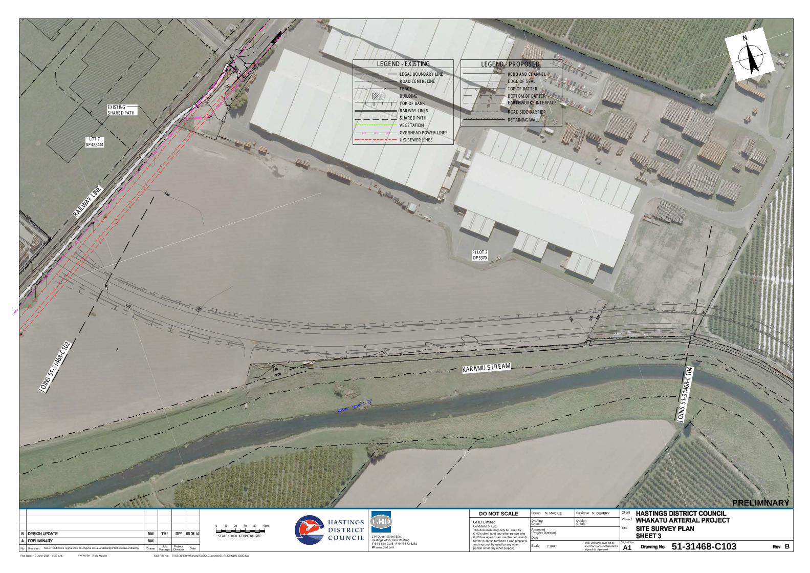
||
| | ||
||
||
||
||| |
| || |
| | | | | | | | | | | | | | | | | | | | | | | | | | | | | | | | | | | | | | | | | | | | | | | | | | | | | | | | | | | || |
| |
|
|
|
| | | | | | | | | | | | | | | | | | | | | | | || |
| || |
||
||
||
||
||
|
||
||
||
|
||
||
||
||
||
||
||
||
||
||
|||||||||||||||||||||||||||||
||
|
|||||||||||||||||||||||||||||||||||||||||||||||||||||||||||||||||| ||
E(OH)
E(OH)
E(OH)
E(OH)
E(OH)
E(OH)
E(OH)
E(OH)
E(OH)
E(OH)
E(OH)
E(OH)
E(OH)
E(OH)
S
S
S
S
S
S
S
S
S
S
S
S
S
S
S
S
S
S
S
S
S
S
S
S
S
S
S
S
S
S
S
S
S
S
S
S
S
S
S
S
S
S
S
S
E(OH)
E(OH)
E(OH)
E(OH)
E(OH)
E(OH)
|
|
|
|
|
|
|
|
|
|
|
|
|
|
|
|
|
|
|
|
|
|
|
|
|
|
|
|
|
|
|
|
|
|
|
|
|
|
|
|
7.006.50
5.50
5.505.50
5.50
5.50
5.50
5.00
5.00
6.00
7.006.50
5.50
5.505.50
5.50
5.50
5.50
5.00
5.00
6.00
6.00
6.00
6.00
5.50
5.50
Pt LOT 2DP5370
RAILWAY LIN
E
KARAMU STREAM
JOIN
S 51-3
1468
-C10
2
JOIN
S 51
-314
68-C
104
LOT 7DP422444
EXISTINGSHARED PATH
This Drawing must not beused for Construction unlesssigned as Approved
Date
CheckDrafting
DateDrawnRevisionNo A1Original Size
Title
Project
Client
Check
DesignerDrawn
Scale
DesignConditions of Use.This document may only be used byGHD's client (and any other person whoGHD has agreed can use this document)for the purpose for which it was preparedand must not be used by any otherperson or for any other purpose.
DO NOT SCALE
Note: * indicates signatures on original issue of drawing or last revision of drawing
Plot Date: Cad File No:9 June 2014 - 4:36 p.m. G:\51\31468 Whakatu\CADD\Drawings\51-31468-C101_C105.dwgPlotted by: Nicki Mackie
(Project Director)Approved
JobManager
ProjectDirector
PRELIMINARY
51-31468-C103 B
N. MACKIE N. DEVERY
1:1000
SCALE 1:1000 AT ORIGINAL SIZE
20100 40 50m30
134 Queen Street EastHastings 4156, New ZealandT 64 6 870 9105 F 64 6 873 5281W www.ghd.com
GHD Limited
LEGEND - EXISTING
FENCE
RAILWAY LINES
LEGAL BOUNDARY LINEROAD CENTRELINE
TOP OF BANK
SHARED PATHVEGETATION
BUILDING
OVERHEAD POWER LINESU/G SEWER LINES
E(OH) E(OH) E(OH)
S S S
LEGEND - PROPOSEDKERB AND CHANNEL
TOP OF BATTERBOTTOM OF BATTER
EDGE OF SEAL
ROAD SIDE BARRIER
RETAINING WALL
EARTHWORKS INTERFACE

||
||
||
||
||
||
||
||
||
||
||
||
||
||
||
||
||
||
||
||
||
||
||
|| |
|
||
||
||
||
||
||
||
||
||
||
||
|
|
|
|
|
|
||
||
||
||
||
||
||
||
||
||
||
| || | | | | | | | | | | | | | | | | | |
| || |
| || |
||
|
||
||
||
||
||
||
||
||
||
||
||
||
||
||
||
||
||
||
||
||
||
||
||
||
||
||
||
||
||
||
||
||
||
||
||
||
||
||
||
||
||
||
||
||||||||||||||||||||||
||
||
||
||
||
||
||
||
||
||
||
||
|
|
|
|
|
|
||
||
||
||
||
||
||
||
||
||
||
||
||
||
||
||
||
||
||
||
||
||
||
||
||
||
||
||
||
||
||
||
||
||
||
|
7.00
6.50
6.505.50
5.50
5.50
5.50
5.50
5.00
5.00 5.00
5.00
6.00
6.00
6.00
7.00
6.50
6.505.50
5.50
5.50
5.50
5.50
5.00
5.00 5.00
5.00
6.00
6.00
6.00
LOT 2DP334708
LOT 2DP334708
LOT 1DP407877
KARA
MU ST
REAM
KARAMU STREAM
JOINS 51-31468-C103
JOINS 51-31468-C105
This Drawing must not beused for Construction unlesssigned as Approved
Date
CheckDrafting
DateDrawnRevisionNo A1Original Size
Title
Project
Client
Check
DesignerDrawn
Scale
DesignConditions of Use.This document may only be used byGHD's client (and any other person whoGHD has agreed can use this document)for the purpose for which it was preparedand must not be used by any otherperson or for any other purpose.
DO NOT SCALE
Note: * indicates signatures on original issue of drawing or last revision of drawing
Plot Date: Cad File No:9 June 2014 - 4:36 p.m. G:\51\31468 Whakatu\CADD\Drawings\51-31468-C101_C105.dwgPlotted by: Nicki Mackie
(Project Director)Approved
JobManager
ProjectDirector
PRELIMINARY
51-31468-C104 B
N. MACKIE N. DEVERY
1:1000
SCALE 1:1000 AT ORIGINAL SIZE
20100 40 50m30
134 Queen Street EastHastings 4156, New ZealandT 64 6 870 9105 F 64 6 873 5281W www.ghd.com
GHD Limited
LEGEND - EXISTING
FENCE
RAILWAY LINES
LEGAL BOUNDARY LINEROAD CENTRELINE
TOP OF BANK
SHARED PATHVEGETATION
BUILDING
OVERHEAD POWER LINESU/G SEWER LINES
E(OH) E(OH) E(OH)
S S S
LEGEND - PROPOSEDKERB AND CHANNEL
TOP OF BATTERBOTTOM OF BATTER
EDGE OF SEAL
ROAD SIDE BARRIER
RETAINING WALL
EARTHWORKS INTERFACE

||
||
||
||
||
||
||
||
||
||
||
||
||
||
||
||
||
||
||
||
||
|||
|
||
||
||
||
||
||
||
|
|
||
||
||
||
||
||
||
||
||
||
||
||
||
||
||
||
||
||
||
||
||
|| |
|
||
||
||
||
||
||
||
||
||
||
||
||
||
||
||
||
||
||
||
||
||
||
||
E(OH
)
E(OH
)
E(OH
)
E(OH
)
E(OH
)E(
OH)
E(O H
)E(
O H)
E(OH
)E(
OH)
E(OH
)
E(OH
)
E(OH
)
E(OH
)
E(OH
)
E(OH
)
E(OH
)
E(OH
)
E(OH
)
E(OH
)
E(OH
)
E(OH)
E(OH) E(OH) E(OH)
E(OH
)
E(OH
)
E(OH
)
E(OH
)
E(OH
)E(
OH)
E(O H
)E(
O H)
E(OH
)E(
OH)
E(OH
)
E(OH
)
E(OH
)
E(OH
)
E(OH
)
E(OH
)
E(OH
)
E(OH
)
E(OH
)
E(OH
)
E(OH
)
E(OH)
E(OH) E(OH) E(OH)
7.00
7.00
6.50
6.50
6.50
6.50
6.50
6.50
5.50
5.50
5.50
5.50
5.50
5.50
5.50
5. 00
5.00
4.50
4.50
4.50
4.50
4.50
6.00
6.00
6.00
6.00
6.00
6.00
6.00
7.00
7.00
6.50
6.50
6.50
6.50
6.50
6.50
5.50
5.50
5.50
5.50
5.50
5.50
5.50
5. 00
5.00
4.50
4.50
4.50
4.50
4.50
6.00
6.00
6.00
6.00
6.00
6.00
6.00
Pt LOT 1DP14513
Pt LOT 2DP13109
LOT 1DP334708
LOT 3DP14513
Pt LOT 1DP432
STAT
E HI
GHW
AY 2
NAPIER ROAD
LOT 2DP334708
JOINS
51-31
468-C
104
STATE HIGHWAY 2
This Drawing must not beused for Construction unlesssigned as Approved
Date
CheckDrafting
DateDrawnRevisionNo A1Original Size
Title
Project
Client
Check
DesignerDrawn
Scale
DesignConditions of Use.This document may only be used byGHD's client (and any other person whoGHD has agreed can use this document)for the purpose for which it was preparedand must not be used by any otherperson or for any other purpose.
DO NOT SCALE
Note: * indicates signatures on original issue of drawing or last revision of drawing
Plot Date: Cad File No:9 June 2014 - 4:36 p.m. G:\51\31468 Whakatu\CADD\Drawings\51-31468-C101_C105.dwgPlotted by: Nicki Mackie
(Project Director)Approved
JobManager
ProjectDirector
PRELIMINARY
51-31468-C105 B
N. MACKIE N. DEVERY
1:1000
SCALE 1:1000 AT ORIGINAL SIZE
20100 40 50m30
134 Queen Street EastHastings 4156, New ZealandT 64 6 870 9105 F 64 6 873 5281W www.ghd.com
GHD Limited
LEGEND - EXISTING
FENCE
RAILWAY LINES
LEGAL BOUNDARY LINEROAD CENTRELINE
TOP OF BANK
SHARED PATHVEGETATION
BUILDING
OVERHEAD POWER LINESU/G SEWER LINES
E(OH) E(OH) E(OH)
S S S
LEGEND - PROPOSEDKERB AND CHANNEL
TOP OF BATTERBOTTOM OF BATTER
EDGE OF SEAL
ROAD SIDE BARRIERRETAINING WALL
EARTHWORKS INTERFACE

E(OH)E(OH)
E(OH
)
E(O H)E(OH)
E(OH)
||
||
||
||
||
||
||
||
||
||
||
||
||
||
||
||
||
||
||
||
||
||
||
||
||
||
||
PAKOWHAI ROAD
KARAMU STREAM
RANG
ITANE
ROAD
JOINS 51-31468-C202
ROAD ALIGNMENT 01
ROAD ALIGNMENT 02
40m INTERNAL DIAMETERROUNDABOUT
PROPOSED BRIDGE
26m INTERNAL DIAMETER
ROUNDABOUT
0
TC 102.996
R -900
CT 337.426
CH 50
CH 100
CH 15 0
CH 200
CH 250
CH 300
CH 350
CH 400
CH 450
CH 500
94
172
298
CH 50
CH 100
CH 150
CH 200
CH 250
CH 300
CH 20
CH 40
CH 60
CH 80
CH 100
CH 120
CH 140
CH 160
CH 180
CH 200
CH 220
59 540
LHS and RHS -3%
VERTICAL ALIGNMENT L=150m L=150mL=9.47m L=89.63m L=85.62m L=172.71m
G=-2.4% G=-0.8% G=1.35% G=-0.94%
K=69.77 K=65.5
R=-900mHORIZONTAL ALIGNMENT L=234.43mL=103m L=328.06m
06.0
5
256.2
5
38.69
6.93
61.2
75.6
7
506.
845
1.31
5.53
756.
645
1.11
5.54
100
6.44
50.8
35.6
210
36.
421
0.90
5.52
125
6.24
51.1
55.1
0
150
6.07
91.0
15.0
7
175
6.00
21.0
05.0
0
200
6.01
41.0
74.9
520
3.31
6.02
21.0
74.9
5
225
6.11
51.1
74.9
5
250
6.30
71.3
84.9
2
275
6.58
71.6
54.9
4
300
6.92
41.8
85.0
5
325
7.26
21.8
85.3
8
337.4
37.
429
2.10
5.33
350
7.59
92.2
95.3
1
375
7.92
72.7
35.2
0
400
8.17
52.9
65.2
1
425
8.32
75.1
73.1
5
438.9
48.3
76.6
21.7
5
450
8.38
46.7
31.6
5
475
8.34
52.9
65.3
9
500
8.21
12.6
55.5
6
525
7.99
12.3
75.6
2
540
7.85
2.22
5.63
SUPER ELEVATION
CHAINAGE
DESIGN SURFACE LEVEL
LEVEL DIFFERENCECUT - / FILL +
EXISTING SURFACE LEVEL
DATUM RL. -7.00
LONGITUDINAL SECTION - ROAD01HORZ 1:1000 VERT 1:200
IP C
H 43
8.93
7RL
8.8
CRES
T CH
452
.36
RL 8
.38
IP C
H 20
3.31
4RL
5.61
9
SAG
CH 1
84.1
3RL
6
IP C
H 38
.685
RL 6
.936
BRIDGE CONSTRUCTION
This Drawing must not beused for Construction unlesssigned as Approved
Date
CheckDrafting
DateDrawnRevisionNo A1Original Size
Title
Project
Client
Check
DesignerDrawn
Scale
DesignConditions of Use.This document may only be used byGHD's client (and any other person whoGHD has agreed can use this document)for the purpose for which it was preparedand must not be used by any otherperson or for any other purpose.
DO NOT SCALE
Note: * indicates signatures on original issue of drawing or last revision of drawing
Plot Date: Cad File No:9 June 2014 - 4:45 p.m. G:\51\31468 Whakatu\CADD\Drawings\51-31468-C201_C205.dwgPlotted by: Nicki Mackie
(Project Director)Approved
JobManager
ProjectDirector
PRELIMINARY
51-31468-C201 C
N. MACKIE N. DEVERY
H: 1:1000, V: 1:200
GHD Limited
LAYOUT PLANSCALE 1:1000
AT ORIGINAL SIZE 0
AT ORIGINAL SIZE0
00
VERTICAL 1:200
HORIZONTAL 1:1000
2 10m864
50m10 30 4020
LEGEND - PROPOSEDKERB AND CHANNEL
CENTRE LINE
TOP OF BATTERBOTTOM OF BATTER
EDGE LINE
EDGE OF SEAL
ROAD SIDE BARRIER
RETAINING WALL
EARTHWORKS INTERFACE
NO PASSINGDRAINAGE SWALES
DRAINAGE CULVERT/PIPE
LEGEND - EXISTING
FENCE
RAILWAY LINES
LEGAL BOUNDARY LINEROAD CENTRELINE
TOP OF BANK
SHARED PATHVEGETATION
BUILDING
OVERHEAD POWER LINESU/G SEWER LINES
E(OH) E(OH) E(OH)
S S S
134 Queen Street EastHastings 4156, New ZealandT 64 6 870 9105 F 64 6 873 5281W www.ghd.com
GHD Limited
DESIGN ROAD CENTRELINE
EXISTING SURFACE LEVEL
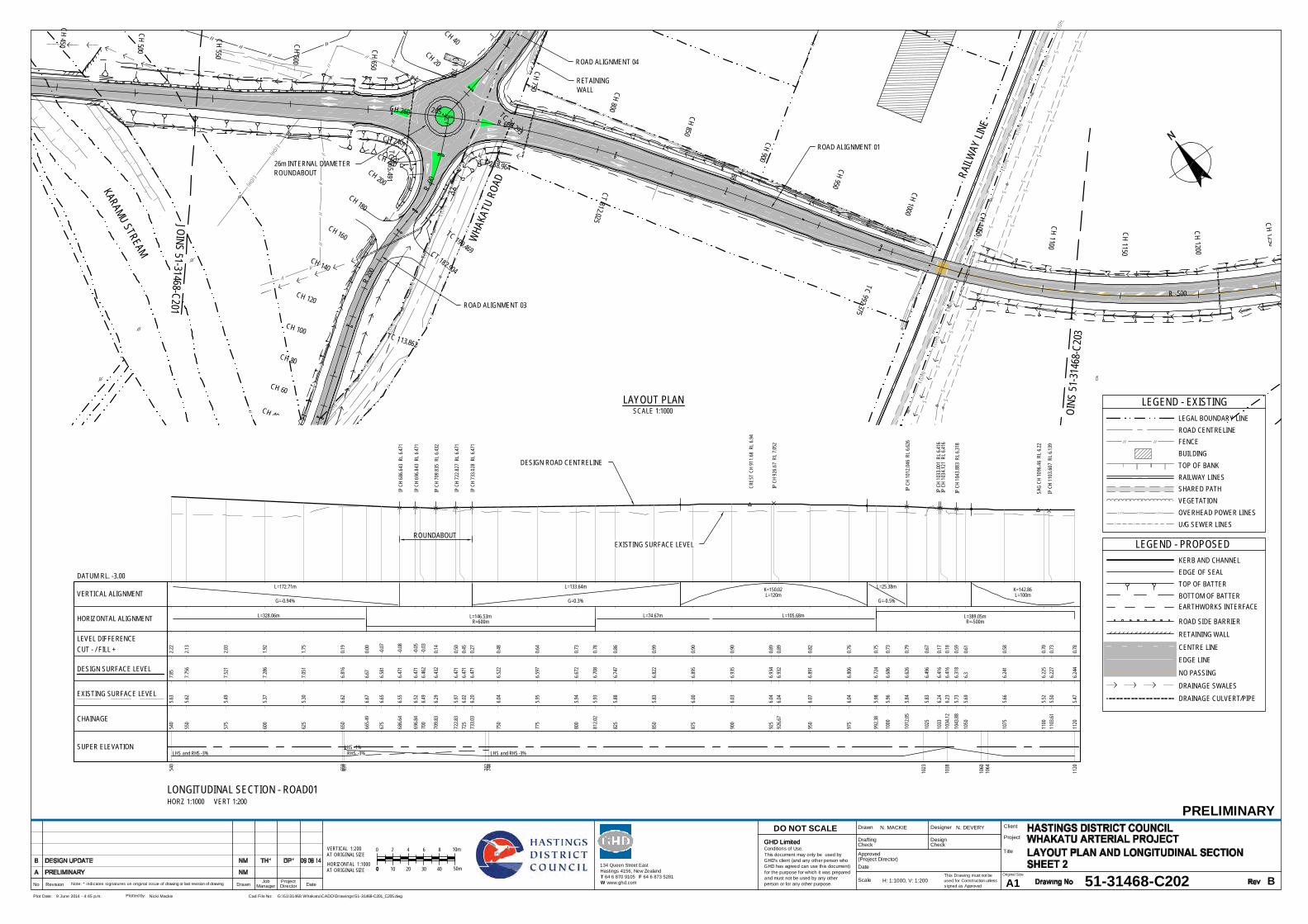
E(OH
)
E(OH
)
E(OH
)
E(OH
)
E(OH
)
E(OH
)
E(OH
)
E(OH
)
E(OH
)
S
S
S
S
S
S
S
S
S
S
S
S
S
S
S
S
S
S
S
S
S
S
S
S
S
S
S
S
S
S
S
S
S
E(OH)
E(OH)
E(OH)
E(OH
)
E(OH
)
E(OH
)
E(OH
)
E(OH
)
E(OH
)
E(OH
)
E(OH)
E(OH)
E(OH)
||
|
| ||
||
||
||
||
||
||
||
||
||
||
||
||
||
||
||
| ||
||
|
||
||
||
||
||
||
||
||
||
||
||
||
||
||
||
||
||
||
||
||
||
||
||
||
||
||
||
||
||
||
||
||
||
||
||
||
||
||
||
||
||
|
||
||
||
||
||
|
||
||
WHA
KATU
ROA
D
KARAMU STREAM
JOIN
S 51
-314
68- C
203
JOINS 51-31468-C201
ROAD ALIGNMENT 01
ROAD ALIGNMENT 04
ROAD ALIGNMENT 03
RETAININGWALL
26m INTERNAL DIAMETERROUNDABOUT
TC 665.491
R 600
CT 812.025
887
TC 992.375
R -500
CH 450
CH 500
CH 550
CH 600
CH 650
CH 700 CH 750 CH 800
CH 850
CH 900
CH 950
CH 1000 CH 1050
CH 1100
CH 1150
CH 1200
CH 1250
0TC 24.293
CH 20
CH 40
TC 113.862
R 20
0
CT 182.904
TC 199.469
R -90
CT 238.964
265
CH 40
CH 60
CH 80
CH 100
CH 120
CH 140
CH 160
CH 180
CH 200
CH 220
CH 240
CH 260
RAILW
AY LI
NE
540
650
651
742
744
1023
1038
1060
1064
1120
LHS and RHS -3%LHS -1%
RHS -3% LHS and RHS -3%
IP C
H 68
6.64
3 R
L 6.4
71
IP C
H 69
6.84
3 R
L 6.4
71
IP C
H 70
9.83
5 R
L 6.4
32
IP C
H 72
2.82
7 R
L 6.4
71
IP C
H 73
3.02
8 R
L 6.4
71
IP C
H 92
6.67
RL
7.052
IP C
H 10
12.0
46 R
L 6.62
6
IP C
H 10
33.0
01 R
L 6.41
6IP
CH
1034
.121
RL 6
.416
IP C
H 10
43.8
83 R
L 6.31
8
IP C
H 11
03.6
07 R
L 6.13
9
CRES
T CH
911
.68
RL
6.94
SAG
CH 1
096.
46 R
L 6.2
2
VERTICAL ALIGNMENT L=120m L=100mL=172.71m L=133.64m L=25.38m
G=-0.94% G=0.3% G=-0.5%
K=150.02 K=142.86
R=600m R=-500mHORIZONTAL ALIGNMENT L=146.53m L=389.05mL=328.06m L=74.67m L=105.68m
540
7.85
2.22
5.63
550
7.75
62.1
35.6
2
575
7.52
12.0
35.4
9
600
7.28
61.9
25.3
7
625
7.05
11.7
55.3
0
650
6.81
60.1
96.6
2
665.4
96.6
70.0
06.6
7
675
6.58
1-0
.076.6
5
686.6
46.
471
-0.08
6.55
696.8
46.
471
-0.05
6.52
700
6.46
2-0
.036.4
9
709.8
36.
432
0.14
6.29
722.8
36.
471
0.50
5.97
725
6.47
10.4
56.0
273
3.03
6.47
10.2
76.2
0
750
6.52
20.4
86.0
4
775
6.59
70.6
45.9
5
800
6.67
20.7
35.9
4
812.0
26.
708
0.78
5.93
825
6.74
70.8
65.8
8
850
6.82
20.9
95.8
3
875
6.89
50.9
06.0
0
900
6.93
50.9
06.0
3
925
6.93
40.8
96.0
492
6.67
6.93
20.8
96.0
4
950
6.89
10.8
26.0
7
975
6.80
60.7
66.0
4
992.3
86.
724
0.75
5.98
1000
6.68
60.7
35.9
6
1012
.056.
626
0.79
5.84
1025
6.49
60.6
75.8
3
1033
6.41
60.1
76.2
410
34.12
6.41
60.1
86.2
3
1043
.886.
318
0.59
5.73
1050
6.30.6
15.6
9
1075
6.24
10.5
85.6
6
1100
6.22
50.7
05.5
211
03.61
6.22
70.7
35.5
0
1120
6.24
40.7
85.4
7
SUPER ELEVATION
CHAINAGE
DESIGN SURFACE LEVEL
LEVEL DIFFERENCECUT - / FILL +
EXISTING SURFACE LEVEL
DATUM RL. -3.00
LONGITUDINAL SECTION - ROAD01HORZ 1:1000 VERT 1:200
This Drawing must not beused for Construction unlesssigned as Approved
Date
CheckDrafting
DateDrawnRevisionNo A1Original Size
Title
Project
Client
Check
DesignerDrawn
Scale
DesignConditions of Use.This document may only be used byGHD's client (and any other person whoGHD has agreed can use this document)for the purpose for which it was preparedand must not be used by any otherperson or for any other purpose.
DO NOT SCALE
Note: * indicates signatures on original issue of drawing or last revision of drawing
Plot Date: Cad File No:9 June 2014 - 4:45 p.m. G:\51\31468 Whakatu\CADD\Drawings\51-31468-C201_C205.dwgPlotted by: Nicki Mackie
(Project Director)Approved
JobManager
ProjectDirector
PRELIMINARY
51-31468-C202 B
N. MACKIE N. DEVERY
H: 1:1000, V: 1:200
GHD Limited
LAYOUT PLANSCALE 1:1000
AT ORIGINAL SIZE 0
AT ORIGINAL SIZE0
00
VERTICAL 1:200
HORIZONTAL 1:1000
2 10m864
50m10 30 4020
LEGEND - PROPOSEDKERB AND CHANNEL
CENTRE LINE
TOP OF BATTERBOTTOM OF BATTER
EDGE LINE
EDGE OF SEAL
ROAD SIDE BARRIER
RETAINING WALL
EARTHWORKS INTERFACE
NO PASSING
DRAINAGE SWALESDRAINAGE CULVERT/PIPE
LEGEND - EXISTING
FENCE
RAILWAY LINES
LEGAL BOUNDARY LINEROAD CENTRELINE
TOP OF BANK
SHARED PATHVEGETATION
BUILDING
OVERHEAD POWER LINESU/G SEWER LINES
E(OH) E(OH) E(OH)
S S S
134 Queen Street EastHastings 4156, New ZealandT 64 6 870 9105 F 64 6 873 5281W www.ghd.com
GHD Limited
DESIGN ROAD CENTRELINE
EXISTING SURFACE LEVELROUNDABOUT

| ||
| ||
||
||
||
||| |
| || |
| | | | | | | | | | | | | | | | | | | | | | | | | | | | | | | | | | | | | | | | | | | | | | | | | | | | | | | | | | | || |
| |
|
|
|
|| | | | | | | | | | | | | | | | | | | | | | |
| || |
| ||
||
||
||
||
||
||
||
||
|
||
||
||
||
||
||
||
||
||
||
|||||||||||||||||||||||||||||
||
|
|||||||||||||||||||||||||||||||||||||||||||||||||||||||||||||||||| | |
E(OH)
E(OH)
E(OH)
E(OH)
E(OH)
E(OH)
E(OH)
S
S
S
S
S
S
S
S
S
S
S
S
S
S
S
S
S
S
S
S
S
S
S
S
S
S
S
|
|
|
|
|
|
|
|
|
|
|
|
|
|
|
|
|
|
|
|
|
|
|
|
|
|
|
|
|
|
|
|
|
|
|
|
|
|
|
|
KARAMU STREAM
JOIN
S 51
-3146
8-C20
2
JOIN
S 51
-314
68-C
204
ROAD ALIGNMENT 01
R -500
CT 1381.423
TS 1645.373
SC 1700.373
CH 1000
CH 1050
CH 1100
CH 1150 CH 1200 CH 1250
CH 1300
CH 1350
CH 1400
CH 1450
CH 1500
CH 1550
CH 1600
CH 1650
CH 1700
CH 1750
CH 1800
RAILWAY LIN
E11
20
1617
1701
1740
LHS and RHS -3%
LHS 6%
RHS -6%
IP C
H 12
90.3
6 R
L 6.8
86
IP C
H 15
88.4
3 R
L 5.9
92
CRES
T CH
129
8.94
RL
6.78
SAG
CH 1
575.
92 R
L 6.0
9
VERTICAL ALIGNMENT L=100m L=120m L=100m L=100mL=76.75m L=188.07m L=80.56m
G=0.4% G=-0.3% G=0.5%
K=142.86 K=171.46 K=125.02 K=100
R=-500m R=240mHORIZONTAL ALIGNMENT L=389.05m L=347.17mL=263.95m
1120
6.24
40.7
85.4
711
256.
253
0.79
5.47
1150
6.32
50.8
75.4
6
1175
6.42
50.9
75.4
6
1200
6.52
51.0
15.5
2
1225
6.62
50.8
95.7
3
1250
6.71
40.9
85.7
3
1275
6.76
71.0
15.7
5
1290
.366.
781
1.02
5.76
1300
6.78
31.0
35.7
6
1325
6.76
40.9
85.7
8
1350
6.70
70.8
85.8
3
1375
6.63
20.7
55.8
8
1381
.426.
613
0.69
5.93
1400
6.55
70.6
55.9
1
1425
6.48
20.6
05.8
8
1450
6.40
70.4
95.9
2
1475
6.33
30.3
45.9
9
1500
6.25
80.2
85.9
7
1525
6.18
30.3
15.8
7
1550
6.11
30.3
45.7
8
1575
6.08
60.4
85.6
0
1588
.436.
092
0.56
5.53
1600
6.10
90.5
95.5
2
1625
6.18
20.7
85.4
0
1645
.376.
277
0.99
5.29
1650
6.31.0
35.2
7
1675
6.42
51.2
05.2
2
1700
6.55
1.37
5.18
1725
6.67
31.4
15.2
7
1740
6.72
81.5
35.2
0
SUPER ELEVATION
CHAINAGE
DESIGN SURFACE LEVEL
LEVEL DIFFERENCECUT - / FILL +
EXISTING SURFACE LEVEL
DATUM RL. -3.00
LONGITUDINAL SECTION - ROAD01HORZ 1:1000 VERT 1:200
This Drawing must not beused for Construction unlesssigned as Approved
Date
CheckDrafting
DateDrawnRevisionNo A1Original Size
Title
Project
Client
Check
DesignerDrawn
Scale
DesignConditions of Use.This document may only be used byGHD's client (and any other person whoGHD has agreed can use this document)for the purpose for which it was preparedand must not be used by any otherperson or for any other purpose.
DO NOT SCALE
Note: * indicates signatures on original issue of drawing or last revision of drawing
Plot Date: Cad File No:9 June 2014 - 4:45 p.m. G:\51\31468 Whakatu\CADD\Drawings\51-31468-C201_C205.dwgPlotted by: Nicki Mackie
(Project Director)Approved
JobManager
ProjectDirector
PRELIMINARY
51-31468-C203 B
N. MACKIE N. DEVERY
H: 1:1000, V: 1:200
GHD Limited
LAYOUT PLANSCALE 1:1000
AT ORIGINAL SIZE 0
AT ORIGINAL SIZE0
00
VERTICAL 1:200
HORIZONTAL 1:1000
2 10m864
50m10 30 4020
LEGEND - PROPOSEDKERB AND CHANNEL
CENTRE LINE
TOP OF BATTERBOTTOM OF BATTER
EDGE LINE
EDGE OF SEAL
ROAD SIDE BARRIERRETAINING WALL
EARTHWORKS INTERFACE
NO PASSING
DRAINAGE SWALES
DRAINAGE CULVERT/PIPE
LEGEND - EXISTING
FENCE
RAILWAY LINES
LEGAL BOUNDARY LINEROAD CENTRELINE
TOP OF BANK
SHARED PATHVEGETATION
BUILDING
OVERHEAD POWER LINESU/G SEWER LINES
E(OH) E(OH) E(OH)
S S S
134 Queen Street EastHastings 4156, New ZealandT 64 6 870 9105 F 64 6 873 5281W www.ghd.com
GHD Limited
DESIGN ROAD CENTRELINE
EXISTING SURFACE LEVEL
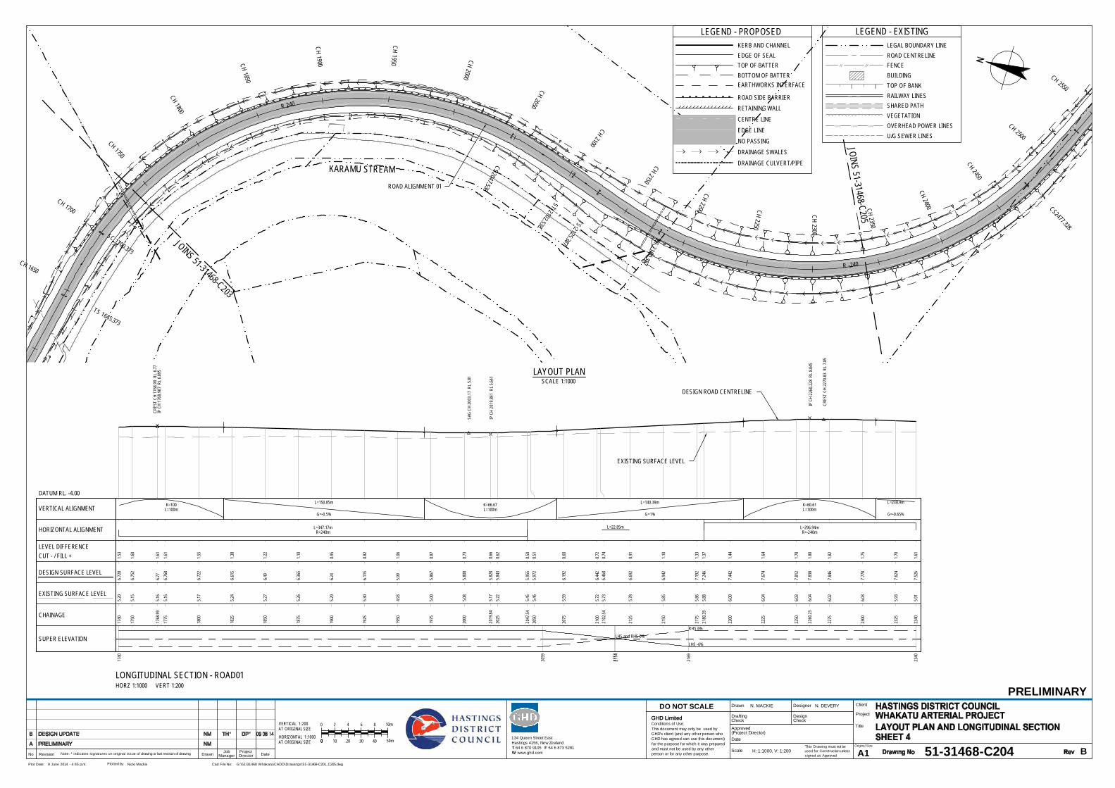
|| |
|
||
||
||
||
||
||
||
||
||
||
||
|
|
|
|
|
|
||
||
||
||
||
||
||
||
||
||
||
| || |
| || | | | | | | | | | | | | | |
| || |
| || |
||
||
|
||
||
||
||
||
||
||
||
||
||
||
||
||
||
||
||
||
||
||
||
||
||
||
||
||
||
||
||
||
||
||
||
||
||
||
||
||
||
||
||
||
||
|||||||||||||||||||||
||
||
||
|
||
||
||
||
||
||
||
||
||
|
|
|
|
|
|
||
||
||
||
||
||
||
||
||
||
||
||
||
KARAMU STREAM
JOINS 51-31468-C203
JOINS 51-31468- C205
ROAD ALIGNMENT 01
TS 1645.373
SC 1700.373
R 240
CS2047.538
ST 2102.538
TS 2125.387 SC 2180.387
R -240
CS2477.328
CH 1650
CH 1700
CH 1750
CH 1800
CH 1850
CH 1900
CH 1950 CH 2000
CH 2050
CH 2100
CH 2150
CH 2200 CH 2250
CH 230 0
CH 2350
CH 2400
CH 2450CH 2500
CH 2550
1740
2059
2113
2114
2169
2340
LHS and RHS 0%
LHS -6%
RHS 6%
IP C
H 17
68.9
87 R
L 6.89
5
IP C
H 20
19.8
41 R
L 5.64
1
IP C
H 22
60.2
28 R
L 8.04
5
CRES
T CH
176
8.99
RL
6.77
CRES
T CH
227
0.83
RL
7.85
SAG
CH 2
003.
17 R
L 5.8
1
VERTICAL ALIGNMENT L=100m L=100m L=100mL=150.85m L=140.39m L=238.9m
G=-0.5% G=1% G=-0.65%
K=100 K=66.67 K=60.61
R=240m R=-240mHORIZONTAL ALIGNMENT L=347.17m L=296.94mL=22.85m
1740
6.72
81.5
35.2
0
1750
6.75
21.6
05.1
5
1768
.996.7
71.6
15.1
6
1775
6.76
81.6
15.1
6
1800
6.72
21.5
55.1
7
1825
6.61
51.3
85.2
4
1850
6.49
1.22
5.27
1875
6.36
51.1
05.2
6
1900
6.24
0.95
5.29
1925
6.11
50.8
25.3
0
1950
5.99
1.06
4.93
1975
5.86
70.8
75.0
0
2000
5.80
80.7
35.0
8
2019
.845.
828
0.66
5.17
2025
5.84
30.6
25.2
2
2047
.545.
955
0.50
5.45
2050
5.97
20.5
15.4
6
2075
6.19
20.6
05.5
9
2100
6.44
20.7
25.7
221
02.54
6.46
80.7
45.7
3
2125
6.69
20.9
15.7
8
2150
6.94
21.1
05.8
5
2175
7.19
21.3
35.8
621
80.39
7.24
61.3
75.8
8
2200
7.44
21.4
46.0
0
2225
7.67
41.6
46.0
4
2250
7.81
21.7
86.0
3
2260
.237.
838
1.80
6.04
2275
7.84
61.8
26.0
2
2300
7.77
81.7
56.0
3
2325
7.62
41.7
05.9
3
2340
7.52
61.6
15.9
1
SUPER ELEVATION
CHAINAGE
DESIGN SURFACE LEVEL
LEVEL DIFFERENCECUT - / FILL +
EXISTING SURFACE LEVEL
DATUM RL. -4.00
LONGITUDINAL SECTION - ROAD01HORZ 1:1000 VERT 1:200
This Drawing must not beused for Construction unlesssigned as Approved
Date
CheckDrafting
DateDrawnRevisionNo A1Original Size
Title
Project
Client
Check
DesignerDrawn
Scale
DesignConditions of Use.This document may only be used byGHD's client (and any other person whoGHD has agreed can use this document)for the purpose for which it was preparedand must not be used by any otherperson or for any other purpose.
DO NOT SCALE
Note: * indicates signatures on original issue of drawing or last revision of drawing
Plot Date: Cad File No:9 June 2014 - 4:45 p.m. G:\51\31468 Whakatu\CADD\Drawings\51-31468-C201_C205.dwgPlotted by: Nicki Mackie
(Project Director)Approved
JobManager
ProjectDirector
PRELIMINARY
51-31468-C204 B
N. MACKIE N. DEVERY
H: 1:1000, V: 1:200
GHD Limited
LAYOUT PLANSCALE 1:1000
AT ORIGINAL SIZE 0
AT ORIGINAL SIZE0
00
VERTICAL 1:200
HORIZONTAL 1:1000
2 10m864
50m10 30 4020
LEGEND - PROPOSEDKERB AND CHANNEL
CENTRE LINE
TOP OF BATTERBOTTOM OF BATTER
EDGE LINE
EDGE OF SEAL
ROAD SIDE BARRIERRETAINING WALL
EARTHWORKS INTERFACE
NO PASSING
DRAINAGE SWALES
DRAINAGE CULVERT/PIPE
LEGEND - EXISTING
FENCE
RAILWAY LINES
LEGAL BOUNDARY LINEROAD CENTRELINE
TOP OF BANK
SHARED PATHVEGETATION
BUILDING
OVERHEAD POWER LINESU/G SEWER LINES
E(OH) E(OH) E(OH)
S S S
134 Queen Street EastHastings 4156, New ZealandT 64 6 870 9105 F 64 6 873 5281W www.ghd.com
GHD Limited
DESIGN ROAD CENTRELINE
EXISTING SURFACE LEVEL

|
|||
|
||
| |
E(OH
)E(
O H)
E(O H
)E(
OH)
E(OH
)
E(OH
)
E(OH
)
E(OH
)
E(OH
)
E(OH
)
E(OH
)
E(OH
)
E(OH
)
E(OH
)
E(OH)
E(OH
)E(
O H)
E(O H
)E(
OH)
E(OH
)
E(OH
)
E(OH
)
E(OH
)
E(OH
)
E(OH
)
E(OH
)
E(OH
)
E(OH
)
E(OH
)
E(OH)
STAT
EHI
GHW
AY 2
NAPIER ROAD
JOINS 5
1-314
68-C2
04 STATE
HIGHWAY 2
ROAD ALIGNMENT 01
ROADALIGNMENT 07
ROADALIGNMENT 10
ROAD ALIGNMENT 11
ROAD ALIGNMENT 11
60m INTERNAL DIAMETERROUNDABOUT
R -240
CS2477.328
S T 2 53 2.3 28
29 41
CH 2250
CH 2300
CH 2350
CH 2400 CH 2450
CH 2500
C H 2 55 0
C H 2 60 0
C H 2 65 0
C H 2 70 0
C H 2 75 0
C H 2 80 0
C H 2 85 0
C H 2 90 00
TC 54.506
R -22
0
CH 50
CH 100
TC 279.132
R -18
0
CT 387.0
81
421
CH 300
CH 350
CH 400
503
TC 608.462
CH 400
CH 450
CH 500
CH 550
CH 600
2340
2477
2505
2559
2812
2900
LHS -6%
RHS 6%
LHS -3% LHS and RHS -3%
IP C
H 26
09.1
25 R
L 5.77
7
IP C
H 27
72.7
35 R
L 6.10
4
IP C
H 28
46.5
38 R
L 7.4
IP C
H 28
55.7
45 R
L 7.4
IP C
H 28
85.7
21 R
L 7.31
SAG
CH 2
640.
89 R
L 5.8
7
VERTICAL ALIGNMENT L=120m L=120mL=238.9m L=43.61m L=13.8m
G=-0.65% G=0.2% G=1.76%
K=141.18 K=77.13
R=-240mHORIZONTAL ALIGNMENT L=296.94m L=408.66m
2340
7.52
61.6
15.9
1
2350
7.46
11.6
15.8
5
2375
7.29
91.6
75.6
3
2400
7.13
61.4
45.6
9
2425
6.97
41.4
35.5
5
2450
6.81
11.6
25.1
9
2475
6.64
91.4
05.2
524
77.33
6.63
41.3
85.2
5
2500
6.48
61.2
15.2
8
2525
6.32
40.9
55.3
7
2532
.336.
276
0.89
5.39
2550
6.16
10.7
35.4
3
2575
6.02
20.5
55.4
7
2600
5.92
80.4
55.4
8
2609
.135.
904
0.42
5.48
2625
5.87
80.3
45.5
4
2650
5.87
20.3
15.5
7
2675
5.90
90.3
75.5
4
2700
5.95
90.4
15.5
4
2725
6.01
80.4
95.5
3
2750
6.14
90.7
45.4
1
2772
.746.
338
0.93
5.40
2775
6.36
0.96
5.40
2800
6.65
21.1
95.4
6
2825
7.02
61.3
85.6
4
2846
.547.4
1.36
6.04
2850
7.41.2
66.1
428
55.74
7.41.2
16.1
9
2875
7.34
20.3
56.9
9
2885
.727.3
10.8
16.5
0
2900
7.35
31.9
35.4
3
SUPER ELEVATION
CHAINAGE
DESIGN SURFACE LEVEL
LEVEL DIFFERENCECUT - / FILL +
EXISTING SURFACE LEVEL
DATUM RL. -3.00
LONGITUDINAL SECTION - ROAD01HORZ 1:1000 VERT 1:200
This Drawing must not beused for Construction unlesssigned as Approved
Date
CheckDrafting
DateDrawnRevisionNo A1Original Size
Title
Project
Client
Check
DesignerDrawn
Scale
DesignConditions of Use.This document may only be used byGHD's client (and any other person whoGHD has agreed can use this document)for the purpose for which it was preparedand must not be used by any otherperson or for any other purpose.
DO NOT SCALE
Note: * indicates signatures on original issue of drawing or last revision of drawing
Plot Date: Cad File No:9 June 2014 - 4:45 p.m. G:\51\31468 Whakatu\CADD\Drawings\51-31468-C201_C205.dwgPlotted by: Nicki Mackie
(Project Director)Approved
JobManager
ProjectDirector
PRELIMINARY
51-31468-C205 B
N. MACKIE N. DEVERY
H: 1:1000, V: 1:200
GHD Limited
LAYOUT PLANSCALE 1:1000
AT ORIGINAL SIZE 0
AT ORIGINAL SIZE0
00
VERTICAL 1:200
HORIZONTAL 1:1000
2 10m864
50m10 30 4020
LEGEND - PROPOSEDKERB AND CHANNEL
CENTRE LINE
TOP OF BATTERBOTTOM OF BATTER
EDGE LINE
EDGE OF SEAL
ROAD SIDE BARRIER
RETAINING WALL
EARTHWORKS INTERFACE
NO PASSING
DRAINAGE SWALESDRAINAGE CULVERT/PIPE
LEGEND - EXISTING
FENCE
RAILWAY LINES
LEGAL BOUNDARY LINEROAD CENTRELINE
TOP OF BANK
SHARED PATHVEGETATION
BUILDING
OVERHEAD POWER LINESU/G SEWER LINES
E(OH) E(OH) E(OH)
S S S
134 Queen Street EastHastings 4156, New ZealandT 64 6 870 9105 F 64 6 873 5281W www.ghd.com
GHD Limited
DESIGN ROAD CENTRELINE
EXISTING SURFACE LEVEL
ROUNDABOUT

E(OH
)
E(O H)E(OH)
E(OH)E(OH)
E(OH)
E(OH)E(OH)
||
||
||
||
||
||
||
||
||
||
||
||
||
||
||
||
||
||
||
||
|
RANG
ITANE
ROAD
PAKOWHAI ROAD
ROAD 01 ALIGNMENT
ROAD 02 ALIGNMENT
RUAHAPIA ROADPAKOW
HAI ROAD
PAKOWHAICOUNTRY PARK
ACCESS CLOSED TORUAHAPIA ROAD
0
TC 102. 996
R -900
CT 337.426
CH 50
CH 100
CH 150
CH 200
CH 250
CH 300
CH 350
CH 400
CH 450
0
94
172
298
TS 311.506
SC 366.506
R -35
0
CT 471.657
472
CH 50
CH 100
CH 150
CH 200
CH 250
CH 300
CH 350
CH 400
CH 450
This Drawing must not beused for Construction unlesssigned as Approved
Date
CheckDrafting
DateDrawnRevisionNo A1Original Size
Title
Project
Client
Check
DesignerDrawn
Scale
DesignConditions of Use.This document may only be used byGHD's client (and any other person whoGHD has agreed can use this document)for the purpose for which it was preparedand must not be used by any otherperson or for any other purpose.
DO NOT SCALE
Note: * indicates signatures on original issue of drawing or last revision of drawing
Plot Date: Cad File No:9 June 2014 - 4:29 p.m. G:\51\31468 Whakatu\CADD\Drawings\51-31468-C211_C214.dwgPlotted by: Nicki Mackie
(Project Director)Approved
JobManager
ProjectDirector
PRELIMINARY
51-31468-C211 C
N. MACKIE N. DEVERY
1:1000
134 Queen Street EastHastings 4156, New ZealandT 64 6 870 9105 F 64 6 873 5281W www.ghd.com
GHD Limited
SCALE 1:1000 AT ORIGINAL SIZE
20100 40 50m30
LEGEND - EXISTING
FENCE
RAILWAY LINES
LEGAL BOUNDARY LINEROAD CENTRELINE
TOP OF BANK
SHARED PATHVEGETATION
BUILDING
OVERHEAD POWER LINESU/G SEWER LINES
E(OH) E(OH) E(OH)
S S S
LEGEND - PROPOSEDKERB AND CHANNEL
CENTRE LINE
TOP OF BATTERBOTTOM OF BATTER
EDGE LINE
EDGE OF SEAL
ROAD SIDE BARRIER
RETAINING WALL
EARTHWORKS INTERFACE
NO PASSING
DRAINAGE SWALESDRAINAGE CULVERT/PIPE

E(OH
)
E(OH
)
E(OH
)
E(OH
)
E(OH
)
E(OH
)
E(OH
)
S
S
S
S
S
S
S
S
S
S
S
S
S
SS
SS
S
SS
SS
S
S
S
S
S
S
S
S
S
S
S
S
S
S
E(OH
)
E(OH)
E(OH)
E(OH)
E(OH
)
E(OH)
E(OH)
E(OH)
E(OH)
E(OH)
E(OH
)
E(OH
)
E(OH
)
E(OH
)
E(OH
)
E(OH
)
E(OH
)
E(OH
)
E(OH
)
E(OH)
E(OH)
E(OH)
||
||
|
| ||
||
||
|
|
||
||
||
||
||
||
||
||
||
||
||
||
||
||
||
||
||
||
||
|| |
||
||
||
||
|
||
||
||
||
||
||
|
||
||
||
||
||
|
||
||
||
||
||
||
||
||
||
||
||
||
||
||
||
||
||
||
||
||
||
||
||
||
||
||
||
||
||
||
||
||
||
||
||
||
||
||
||
||
||
|
||
||
||
||
||
|
||
||
RAILW
AY LI
NE
KARAMU STREAM
WHA
KATU
ROA
D
ROAD ALIGNMENT 01
ROAD ALIGNMENT 03
ROAD ALIGNMENT 04
ROAD ALIGNMENT 01
RUAHAPIA ROAD
SEMI - T RAILER
SEMI - T RAILER
SEMI - T RAILER
SEMI - T RAILER
CT 337.426
R 600
CT 812.025
887
TC 992.375
CH 300
CH 350
CH 400
CH 450
CH 500
CH 550
CH 600
CH 800 CH 850 CH 900 CH 950 CH 1000
CH 1050
R -30
0
CT 146.751
168
0
TC 1.064
R -12
0
CT 51.955
TC 113.862
R 20
0
CT 182.904
TC 199.469
R -90
CH 160
CH 140CH 120
CH 100CH 80
CH 60CH 40CH 20
CH 260
CH 240CH 220CH 200
CH 180CH 160
CH 140
CH 120
CH 100
CH 80
CH 60CH 40
CH 20
CT 238.964
CH 750
CH 700
CH 650
WHA
KATU
ROA
D
This Drawing must not beused for Construction unlesssigned as Approved
Date
CheckDrafting
DateDrawnRevisionNo A1Original Size
Title
Project
Client
Check
DesignerDrawn
Scale
DesignConditions of Use.This document may only be used byGHD's client (and any other person whoGHD has agreed can use this document)for the purpose for which it was preparedand must not be used by any otherperson or for any other purpose.
DO NOT SCALE
Note: * indicates signatures on original issue of drawing or last revision of drawing
Plot Date: Cad File No:9 June 2014 - 4:29 p.m. G:\51\31468 Whakatu\CADD\Drawings\51-31468-C211_C214.dwgPlotted by: Nicki Mackie
(Project Director)Approved
JobManager
ProjectDirector
PRELIMINARY
51-31468-C212 C
N. MACKIE N. DEVERY
1:1000
134 Queen Street EastHastings 4156, New ZealandT 64 6 870 9105 F 64 6 873 5281W www.ghd.com
GHD Limited
SCALE 1:1000 AT ORIGINAL SIZE
20100 40 50m30
LEGEND - EXISTING
FENCE
RAILWAY LINES
LEGAL BOUNDARY LINEROAD CENTRELINE
TOP OF BANK
SHARED PATHVEGETATION
BUILDING
OVERHEAD POWER LINESU/G SEWER LINES
E(OH) E(OH) E(OH)
S S S
LEGEND - PROPOSEDKERB AND CHANNEL
CENTRE LINE
TOP OF BATTERBOTTOM OF BATTER
EDGE LINE
EDGE OF SEAL
ROAD SIDE BARRIER
RETAINING WALL
EARTHWORKS INTERFACE
NO PASSING
DRAINAGE SWALESDRAINAGE CULVERT/PIPE

||
||
||
||
||
||
|||
|
||
||
||
||
||
||
||
||
||
||
||
||
||
||
||
||
||
||
||
||
||
||
||
||
||
||
||
|
|
||
||
||
||
||
||
||
||
||
||
||
||
||
||
||
||
||
||
||
||
||
||
||
||
||
||
| |
E(OH
)
E(OH
)
E(OH
)
E(OH
)
E(OH
)
E(OH
)
E(OH
)
E(OH
)
E(OH
)
E(OH
)
E(OH
)
E(OH)
E(OH
)
E(OH
)
S
S
S
S
S
S
S
S
S
S
S
S
S
S
S
S
S
S
S
S
S
S
S
S
S
S
S
S
S
SS
S
S
S
S
S
S
S
S
S
S
S
S
S
S
S
S
S
S
S
E(OH
)
E(OH
)
E(OH
)
E(OH
)
E(OH
)
E(OH
)
E(OH
)
E(OH
)
E(OH
)
E(OH
)
E(OH
)
||
||
||
||
||
||
||
||
|| |
||
||
||
||
|
||
||
||
||
||
||
|
||
||
||
||
||
|
||
||
||
||
||
||
||
||
||
||
||
||
||
||
||
||
||
||
||
||
||
||
||
||
||
||
||
||
||
||
||
||
||
||
||
||
||
||
||
||
||
|
||
||
||
||
||
|
RAILW
AY LI
NE
WHA
KATU
ROA
D
ROAD ALIGNMENT 04
ROAD ALIGNMENT 01
SEMI - T RAILER
SEMI - T RAILER
SEMI - T RAILER
SEMI - T RAILER
R 600
CT 812.025
887
TC 992.375
R -500
CT 1381.423
CH 800 CH 850 CH 900 CH 950 CH 1000
CH 1050
CH 1100
CH 1150
C H 1200
CH 12 50
CH 1300
CH 1350
CH 1400
CH 1450
CH 1500
CH 1550R
-300
CT 146.751
168
TC 199.469
CH 160
CH 140CH 120
CH 100CH 80
CT 238.964
CH 750
This Drawing must not beused for Construction unlesssigned as Approved
Date
CheckDrafting
DateDrawnRevisionNo A1Original Size
Title
Project
Client
Check
DesignerDrawn
Scale
DesignConditions of Use.This document may only be used byGHD's client (and any other person whoGHD has agreed can use this document)for the purpose for which it was preparedand must not be used by any otherperson or for any other purpose.
DO NOT SCALE
Note: * indicates signatures on original issue of drawing or last revision of drawing
Plot Date: Cad File No:9 June 2014 - 4:29 p.m. G:\51\31468 Whakatu\CADD\Drawings\51-31468-C211_C214.dwgPlotted by: Nicki Mackie
(Project Director)Approved
JobManager
ProjectDirector
PRELIMINARY
51-31468-C213 C
N. MACKIE N. DEVERY
1:1000
134 Queen Street EastHastings 4156, New ZealandT 64 6 870 9105 F 64 6 873 5281W www.ghd.com
GHD Limited
SCALE 1:1000 AT ORIGINAL SIZE
20100 40 50m30
LEGEND - EXISTING
FENCE
RAILWAY LINES
LEGAL BOUNDARY LINEROAD CENTRELINE
TOP OF BANK
SHARED PATHVEGETATION
BUILDING
OVERHEAD POWER LINESU/G SEWER LINES
E(OH) E(OH) E(OH)
S S S
LEGEND - PROPOSEDKERB AND CHANNEL
CENTRE LINE
TOP OF BATTERBOTTOM OF BATTER
EDGE LINE
EDGE OF SEAL
ROAD SIDE BARRIER
RETAINING WALL
EARTHWORKS INTERFACE
NO PASSINGDRAINAGE SWALES
DRAINAGE CULVERT/PIPE

||
||
||
||
||
||
||
||
||
||
|
|
||
||
||
||
||
||
||
||
||
||
||
||
||
||
||
||
||
||
||
||
||
||
||
||
||
|
|
||
||
||
||
||
||
||
||
||
|||
|
||
||
||
||
| |
||
||
||
||
||
||
||
| |
||
||
||
||
||
||
||
||
||
||
||
||
|
|
||
||
||
||
||
||
||
||
||
||
||
||
||
||
||
|||
||
||
||
||
||
||
||
||
||
|
||
||
||
||
||
|
|
||
||
||
||
||
E(OH
)
E(OH
)
E(OH
)
E(OH
)
E(OH
)
E(OH
)
E(OH
)
E(OH)
E(OH
)
E(OH
)
E(OH
)
E(OH
)
E(OH
)
E(OH
)
E(OH
)
E(OH)
STAT
E HI
GHWA
Y 2
NAPIER ROAD
STATE HIGHWAY 2
ROAD ALIGNMENT 01
ROAD ALIGNMENT 11
ROAD ALIGNMENT 11
ROAD ALIGNMENT 10
ROAD ALIGNMENT 07
PILCHER ROAD
R 240
CS2047.538
ST 2102.538
TS 2125.387
SC 2180.387
R -240
CS2477.328
ST 25 32.3 28
29 41
CH 1800
CH 1850
CH 1900
CH 1950
CH 2000
CH 2050
CH 2100
CH 2150
CH 2200
CH 2250
CH 2300
CH 2350 CH 2400
CH 2450
CH 2500
CH 25 50
CH 26 00
CH 26 50
CH 27 00
CH 27 50
CH 28 00
CH 28 50
CH 29 00
0
TC 54.506
R -22
0
CT 168.689
TC 221.347
R 280
CT 474.748
528CH 100
CH 150
CH 200
CH 250
CH 300
CH 350
CH 400
CH 450
CH 500
0
TC 77.273
R 72
0
CT 223.013
TC 279.132
R -18
0
421
CH 50
CH 100
CH 150
CH 200
CH 250
CH 300
CH 350
CH 400
0
TC 78.570
R -550
CT 255.000
503
TC 608.462
R 620
CT 740.332
823
CH 50
CH 100
CH 150
CH 200
CH 250
CH 300
CH 350
CH 400
CH 450
CH 500
CH 550
CH 600
CH 650
CH 700
CH 750
CH 800
This Drawing must not beused for Construction unlesssigned as Approved
Date
CheckDrafting
DateDrawnRevisionNo A1Original Size
Title
Project
Client
Check
DesignerDrawn
Scale
DesignConditions of Use.This document may only be used byGHD's client (and any other person whoGHD has agreed can use this document)for the purpose for which it was preparedand must not be used by any otherperson or for any other purpose.
DO NOT SCALE
Note: * indicates signatures on original issue of drawing or last revision of drawing
Plot Date: Cad File No:9 June 2014 - 4:29 p.m. G:\51\31468 Whakatu\CADD\Drawings\51-31468-C211_C214.dwgPlotted by: Nicki Mackie
(Project Director)Approved
JobManager
ProjectDirector
PRELIMINARY
51-31468-C214 B
N. MACKIE N. DEVERY
1:2000
134 Queen Street EastHastings 4156, New ZealandT 64 6 870 9105 F 64 6 873 5281W www.ghd.com
GHD Limited0
SCALE 1:2000 AT ORIGINAL SIZE
4020 80 100m60
LEGEND - EXISTING
FENCE
RAILWAY LINES
LEGAL BOUNDARY LINEROAD CENTRELINE
TOP OF BANK
SHARED PATHVEGETATION
BUILDING
OVERHEAD POWER LINESU/G SEWER LINES
E(OH) E(OH) E(OH)
S S S
LEGEND - PROPOSEDKERB AND CHANNEL
CENTRE LINE
TOP OF BATTERBOTTOM OF BATTER
EDGE LINE
EDGE OF SEAL
ROAD SIDE BARRIER
RETAINING WALL
EARTHWORKS INTERFACE
NO PASSINGDRAINAGE SWALES
DRAINAGE CULVERT/PIPEHASTINGS
HAVELOCK NORTH
NAPIER

HORZ 1:1000 VERT 1:200LONGITUDINAL SECTION - ROAD02 - PAKOWHAI ROAD
IP C
H 67
.56
RL 6
.44
IP C
H 13
3.78
RL
7.81
IP C
H 14
3.42
RL
7.81
IP C
H 16
5.12
RL
7.74
IP C
H 19
3.16
RL
7.83
IP C
H 20
2.8
RL 7
.83
IP C
H 27
4.73
RL
5.91
IP C
H 35
3.77
RL
6.35
SAG
CH 3
00.8
7 RL
6.09
VERTICAL ALIGNMENT L=80m L=80mL=27.64m L=26.22m L=31.94m L=39.04m L=56.23m
G=0.5% G=2.06% G=-2.67% G=0.56% G=1.01%
K=51.14 K=24.75
HORIZONTAL ALIGNMENT L=94.25m L=78.02m L=125.68m L=13.56m
0.00
6.10
3-0
.006.1
1
20.00
6.20
30.0
76.1
3
40.00
6.31
90.1
76.1
5
60.00
6.50
60.3
76.1
3
67.56
6.59
80.4
76.1
3
80.00
6.77
20.6
66.1
2
100.0
07.
116
1.02
6.10
120.0
07.
524
1.45
6.08
133.7
87.
808
1.75
6.06
140.0
07.
808
1.75
6.06
143.4
27.
808
1.75
6.06
160.0
07.
758
1.71
6.05
165.1
27.
743
1.69
6.05
180.0
07.
788
1.74
6.04
193.1
67.
827
1.78
6.05
200.0
07.
827
1.78
6.05
202.8
07.
827
1.78
6.05
220.0
07.
368
1.32
6.05
240.0
06.
839
0.78
6.05
260.0
06.
428
0.38
6.05
274.7
36.
228
0.18
6.04
280.0
06.
178
0.14
6.04
300.0
06.
090
0.02
6.07
311.5
16.
113
0.00
6.11
320.0
06.
159
0.01
6.14
340.0
06.
271
0.06
6.22
353.7
76.
348
0.09
6.25
360.0
06.
411
0.10
6.31
366.5
16.
477
0.08
6.39
380.0
06.
613
0.05
6.57
400.0
06.
816
-0.03
6.85
CHAINAGE
DESIGN SURFACE LEVEL
LEVEL DIFFERENCECUT - / FILL +
EXISTING SURFACE LEVEL
DATUM RL. 2.00
LONGITUDINAL SECTION - ROAD03 - WHAKATU ROAD SOUTH HORZ 1:1000 VERT 1:200
IP C
H 78
.72
RL 6
.31
IP C
H 18
4.87
RL
5.25
IP C
H 23
3.85
RL
5.96
SAG
CH 1
78.4
7 RL
5.46
VERTICAL ALIGNMENT L=70m L=70mL=43.99m L=36.15m L=13.99m L=17.33m
G=-0.3% G=-1% G=1.45% G=2.5%
K=100.07 K=28.62
R=-120.00m R=200.00m R=-90.00mHORIZONTAL ALIGNMENT L=50.89m L=69.04m L=39.49mL=1.06m L=61.91m L=16.57m
0.00
6.54
8-0
.006.5
51.0
66.
545
-0.00
6.55
20.00
6.48
8-0
.046.5
3
40.00
6.42
80.0
66.3
7
51.96
6.38
80.5
45.8
5
60.00
6.35
40.7
35.6
2
78.72
6.25
00.5
65.6
980
.006.
242
0.55
5.69
100.0
06.
089
0.56
5.53
113.8
65.
960
0.58
5.38
120.0
05.
899
0.59
5.31
140.0
05.
699
0.78
4.92
160.0
05.
517
0.89
4.63
180.0
05.
458
0.85
4.61
182.9
05.
461
0.80
4.67
184.8
75.
464
0.76
4.71
199.4
75.
534
0.70
4.84
220.0
05.
759
1.10
4.65
233.8
55.
959
-0.12
6.08
238.9
66.
087
-0.93
7.02
240.0
06.
113
-0.91
7.03
CHAINAGE
DESIGN SURFACE LEVEL
LEVEL DIFFERENCECUT - / FILL +
EXISTING SURFACE LEVEL
DATUM RL. 1.00
LONGITUDINAL SECTION - ROAD04 - WHAKATU ROAD NORTHHORZ 1:1000 VERT 1:200
IP C
H 23
RL
6.18
IP C
H 13
0.36
RL
5.52
VERTICAL ALIGNMENTL=10m L=107.36m L=10m
G=-2.5% G=-0.62% G=-1.2%
R=-300.00mHORIZONTAL ALIGNMENT L=122.46mL=24.29m
0.00
6.50
20.00
6.25
70.2
85.9
823
.006.
182
0.18
6.01
24.29
6.17
40.2
35.9
4
40.00
6.07
70.3
65.7
2
60.00
5.95
40.3
45.6
1
80.00
5.83
00.2
65.5
7
100.0
05.
707
0.19
5.52
120.0
05.
584
0.12
5.46
130.3
65.
520
0.09
5.43
140.0
05.
404
0.00
5.40
CHAINAGE
DESIGN SURFACE LEVEL
LEVEL DIFFERENCECUT - / FILL +
EXISTING SURFACE LEVEL
DATUM RL. 2.00
This Drawing must not beused for Construction unlesssigned as Approved
Date
CheckDrafting
DateDrawnRevisionNo A1Original Size
Title
Project
Client
Check
DesignerDrawn
Scale
DesignConditions of Use.This document may only be used byGHD's client (and any other person whoGHD has agreed can use this document)for the purpose for which it was preparedand must not be used by any otherperson or for any other purpose.
DO NOT SCALE
Note: * indicates signatures on original issue of drawing or last revision of drawing
Plot Date: Cad File No:9 June 2014 - 4:39 p.m. G:\51\31468 Whakatu\CADD\Drawings\51-31468-C215_C217.dwgPlotted by: Nicki Mackie
(Project Director)Approved
JobManager
ProjectDirector
PRELIMINARY
51-31468-C215 B
N. MACKIE N. DEVERY
H: 1:1000, V: 1:200
134 Queen Street EastHastings 4156, New ZealandT 64 6 870 9105 F 64 6 873 5281W www.ghd.com
GHD Limited
AT ORIGINAL SIZE 0
AT ORIGINAL SIZE0
00
VERTICAL 1:200
HORIZONTAL 1:1000
2 10m864
50m10 30 4020
ROAD 01 WHAKATUARTERIAL
ROAD 01 WHAKATUARTERIAL
ROUNDABOUT
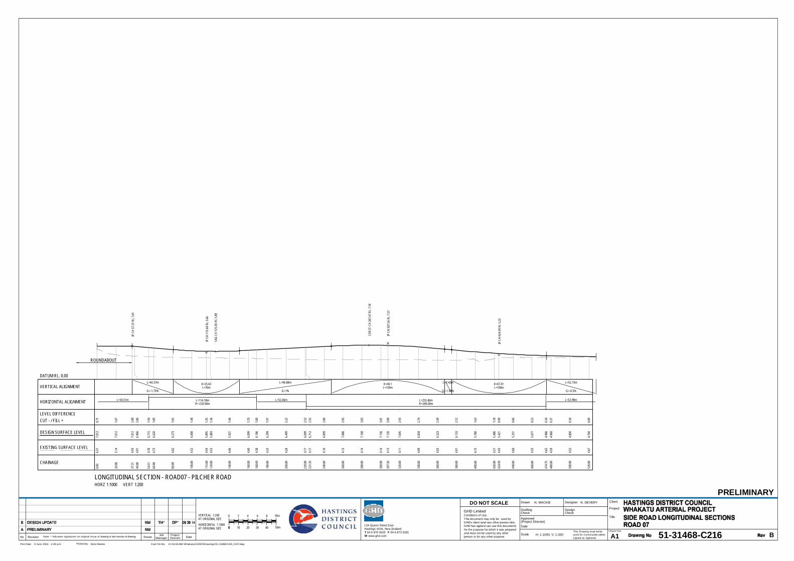
LONGITUDINAL SECTION - ROAD07 - PILCHER ROAD HORZ 1:1000 VERT 1:200
IP C
H 37
.31
RL 7
.01
IP C
H 11
5.68
RL
5.66
IP C
H 30
7.56
RL
7.57
IP C
H 42
4.99
RL
5.23
CRES
T CH
287
.67
RL 7
.18
SAG
CH 1
25.0
5 RL
5.88
VERTICAL ALIGNMENT L=70m L=120m L=100mL=43.37m L=96.88m L=7.43m L=52.73m
G=-1.73% G=1% G=-1.99% G=-0.5%
K=25.63 K=40.1 K=67.01
R=-220.00m R=280.00mHORIZONTAL ALIGNMENT L=114.18m L=253.40mL=54.51m L=52.66m L=52.98m
0.00
7.01
20.7
16.3
1
20.00
7.01
21.8
75.1
4
37.31
7.01
22.0
84.9
340
.006.
966
2.06
4.91
54.51
6.71
51.9
44.7
860
.006.
620
1.89
4.73
80.00
6.27
31.6
54.6
2
100.0
06.
000
1.48
4.52
115.6
85.
895
1.35
4.54
120.0
05.
883
1.36
4.53
140.0
05.
921
1.46
4.46
160.0
06.
099
1.70
4.40
168.6
96.
186
1.80
4.38
180.0
06.
299
1.97
4.33
200.0
06.
499
2.22
4.28
220.0
06.
699
2.53
4.17
221.3
56.
712
2.55
4.17
240.0
06.
899
2.80
4.10
260.0
07.
080
2.95
4.13
280.0
07.
168
3.03
4.14
300.0
07.
156
3.01
4.14
307.5
67.
126
3.00
4.13
320.0
07.
045
2.93
4.11
340.0
06.
834
2.74
4.09
360.0
06.
523
2.49
4.03
380.0
06.
133
2.12
4.01
400.0
05.
780
1.63
4.15
420.0
05.
486
1.18
4.31
424.9
95.
421
0.99
4.43
440.0
05.
251
0.66
4.60
460.0
05.
077
0.53
4.55
474.7
54.
986
0.34
4.65
480.0
04.
960
0.37
4.59
500.0
04.
860
0.34
4.52
520.0
04.
760
0.09
4.67
CHAINAGE
DESIGN SURFACE LEVEL
LEVEL DIFFERENCECUT - / FILL +
EXISTING SURFACE LEVEL
DATUM RL. 0.00
This Drawing must not beused for Construction unlesssigned as Approved
Date
CheckDrafting
DateDrawnRevisionNo A1Original Size
Title
Project
Client
Check
DesignerDrawn
Scale
DesignConditions of Use.This document may only be used byGHD's client (and any other person whoGHD has agreed can use this document)for the purpose for which it was preparedand must not be used by any otherperson or for any other purpose.
DO NOT SCALE
Note: * indicates signatures on original issue of drawing or last revision of drawing
Plot Date: Cad File No:9 June 2014 - 4:39 p.m. G:\51\31468 Whakatu\CADD\Drawings\51-31468-C215_C217.dwgPlotted by: Nicki Mackie
(Project Director)Approved
JobManager
ProjectDirector
PRELIMINARY
51-31468-C216 B
N. MACKIE N. DEVERY
H: 1:1000, V: 1:200
134 Queen Street EastHastings 4156, New ZealandT 64 6 870 9105 F 64 6 873 5281W www.ghd.com
GHD Limited
AT ORIGINAL SIZE 0
AT ORIGINAL SIZE0
00
VERTICAL 1:200
HORIZONTAL 1:1000
2 10m864
50m10 30 4020
ROUNDABOUT

LONGITUDINAL SECTION - ROAD10HORZ 1:1000 VERT 1:200
IP C
H 17
0 RL
7.94
IP C
H 32
6.98
RL
6.53
IP C
H 38
3.94
RL
7.16
CRES
T CH
165
.9 R
L 7.
74
SAG
CH 3
22.8
1 RL
6.73
VERTICAL ALIGNMENT L=100m L=80mL=120.2m L=66.98m L=16.96m
G=0.76% G=-0.9% G=1.11%
K=60.11 K=39.81
R=720.00m R=-180.00mHORIZONTAL ALIGNMENT L=145.74m L=107.95mL=77.27m L=56.12m L=34.30m
0.00
6.64
6
20.00
6.79
9
40.00
6.95
20.1
56.8
0
60.00
7.10
50.2
96.8
2
77.27
7.23
70.5
36.7
180
.007.
257
0.43
6.83
100.0
07.
410
0.69
6.73
120.0
07.
563
0.99
6.57
140.0
07.
682
1.27
6.41
160.0
07.
735
1.43
6.30
170.0
07.
737
1.73
6.01
180.0
07.
722
1.67
6.05
200.0
07.
641
1.90
5.75
220.0
07.
495
1.77
5.72
223.0
17.
468
1.79
5.67
240.0
07.
315
1.69
5.62
260.0
07.
135
1.40
5.74
279.1
36.
962
1.40
5.56
300.0
06.
796
1.31
5.49
320.0
06.
732
1.31
5.43
326.9
86.
733
1.33
5.41
340.0
06.
768
1.44
5.33
360.0
06.
904
1.39
5.51
380.0
07.
120
1.64
5.48
383.9
47.
164
1.62
5.55
387.0
87.
164
1.57
5.59
400.0
07.
164
1.65
5.51
420.0
07.
164
0.87
6.30
421.3
87.
164
0.86
6.31
CHAINAGE
DESIGN SURFACE LEVEL
LEVEL DIFFERENCECUT - / FILL +
EXISTING SURFACE LEVEL
DATUM RL. 2.00
LONGITUDINAL SECTION - ROAD11 - STATE HIGHWAY 2 NORTH HORZ 1:1000 VERT 1:200
IP C
H 89
.41
RL 4
.7
IP C
H 19
4.84
RL
5.02
IP C
H 32
2.24
RL
6.16
IP C
H 46
3.39
RL
6.8
IP C
H 47
3.03
RL
6.8
IP C
H 53
4.62
RL
7.03
IP C
H 54
3.84
RL
7.03
VERTICAL ALIGNMENT L=80mL=89.41m L=65.43m L=87.4m L=141.15m L=59.64m
G=0.4% G=0.3% G=0.9% G=0.45% G=0.5%
K=133.33
R=-550.00mHORIZONTAL ALIGNMENT L=176.43mL=78.57m L=248.43m L=105.03m
-0.00
4.34
2-0
.094.4
3
20.00
4.42
20.0
24.4
0
40.00
4.50
20.0
14.4
9
60.00
4.58
20.0
44.5
4
78.57
4.65
60.1
94.4
780
.004.
662
0.09
4.57
89.41
4.70
00.1
74.5
3
100.0
04.
731
0.14
4.60
120.0
04.
791
0.23
4.56
140.0
04.
851
0.21
4.64
160.0
04.
912
0.36
4.55
180.0
04.
995
0.25
4.75
194.8
45.
076
0.40
4.67
200.0
05.
108
0.38
4.73
220.0
05.
251
0.40
4.85
240.0
05.
422
0.48
4.94
255.0
05.
557
0.66
4.90
260.0
05.
602
0.67
4.93
280.0
05.
782
0.79
4.99
300.0
05.
962
0.87
5.09
320.0
06.
142
0.90
5.25
322.2
46.
163
0.90
5.27
340.0
06.
243
0.84
5.41
360.0
06.
332
0.77
5.56
380.0
06.
422
0.69
5.73
400.0
06.
512
0.40
6.11
420.0
06.
602
0.40
6.20
440.0
06.
692
0.42
6.28
460.0
06.
782
0.37
6.41
463.3
96.
798
0.47
6.33
473.0
36.
798
0.50
6.29
480.0
06.
824
0.48
6.34
500.0
06.
900
0.64
6.26
520.0
06.
976
0.15
6.83
534.6
27.
032
-0.08
7.11
540.0
07.
032
0.07
6.96
543.8
47.
032
0.09
6.94
560.0
07.
112
-0.04
7.15
580.0
07.
212
0.00
7.21
600.0
07.
312
0.17
7.14
CHAINAGE
DESIGN SURFACE LEVEL
LEVEL DIFFERENCECUT - / FILL +
EXISTING SURFACE LEVEL
DATUM RL. 1.00
LONGITUDINAL SECTION - ROAD11 - STATE HIGHWAY 2 NORTH HORZ 1:1000 VERT 1:200
IP C
H 66
3.48
RL
7.63
CRES
T CH
635
.91
RL 7
.41
VERTICAL ALIGNMENT L=120mL=59.64m L=74.2m
G=0.5% G=-1.35%
K=64.86
R=620.00mHORIZONTAL ALIGNMENT L=131.87mL=105.03m L=82.67m
600.0
07.
312
0.17
7.14
608.4
67.
353
0.17
7.19
620.0
07.
391
0.25
7.14
640.0
07.
410
0.37
7.04
660.0
07.
366
0.41
6.96
663.4
87.
352
0.41
6.95
680.0
07.
261
0.41
6.85
700.0
07.
094
0.29
6.80
720.0
06.
866
0.17
6.70
740.0
06.
597
0.06
6.54
760.0
06.
327
-0.01
6.33
780.0
06.
057
-0.02
6.07
800.0
05.
827
0.06
5.76
CHAINAGE
DESIGN SURFACE LEVEL
LEVEL DIFFERENCECUT - / FILL +
EXISTING SURFACE LEVEL
DATUM RL. 2.00
This Drawing must not beused for Construction unlesssigned as Approved
Date
CheckDrafting
DateDrawnRevisionNo A1Original Size
Title
Project
Client
Check
DesignerDrawn
Scale
DesignConditions of Use.This document may only be used byGHD's client (and any other person whoGHD has agreed can use this document)for the purpose for which it was preparedand must not be used by any otherperson or for any other purpose.
DO NOT SCALE
Note: * indicates signatures on original issue of drawing or last revision of drawing
Plot Date: Cad File No:9 June 2014 - 4:39 p.m. G:\51\31468 Whakatu\CADD\Drawings\51-31468-C215_C217.dwgPlotted by: Nicki Mackie
(Project Director)Approved
JobManager
ProjectDirector
PRELIMINARY
51-31468-C217 B
N. MACKIE N. DEVERY
H: 1:1000, V: 1:200
134 Queen Street EastHastings 4156, New ZealandT 64 6 870 9105 F 64 6 873 5281W www.ghd.com
GHD Limited
AT ORIGINAL SIZE 0
AT ORIGINAL SIZE0
00
VERTICAL 1:200
HORIZONTAL 1:1000
2 10m864
50m10 30 4020
ROUNDABOUT
ROUNDABOUT

3.5mTRAFFIC LANE
3.5mTRAFFIC LANE
2.0mSEALED
SHOULDER
1.2mVERGE
VARIES3.5mTRAFFIC LANE
3.5mTRAFFIC LANE
2.0mSHOULDER
1.2m3.3mVERGE
VARIES0.6m
SWALE
ROAD 01
6.5mCLEAR ZONE
3%3%10%6
1
0%
SECTIONA- 50SCALE 1 :
3% 3%
SEAL:
SUBGRADE
SUBBASE
BASECOURSE
SEAL:
10%EXISTING GROUNDSURFACE
EXCAVATE AND REMOVE TOPSOIL ANDUNSUITABLE MATERIAL. BACKFILLWITH SUBGRADE MATERIAL
KERB AND CHANNELBATTER 1:4 BATTER 1:4
BATTER 1:4
ROAD 01
3.5mTRAFFIC LANE
1.5mSEALED
SHOULDER
VARIES0.6m3.5m
TRAFFIC LANE
SWALE
5.0mVERGE
1.5mSEALED
SHOULDER
VARIES0.6m
SWALE
5.0mVERGE
6.5mCLEAR ZONE
61
0%
BATTER 1:4 BATTER 1:4
3% 3%
SUBBASE
BASECOURSEEXCAVATE AND REMOVE TOPSOIL ANDUNSUITABLE MATERIAL. BACKFILLWITH SUBGRADE MATERIAL
BATTER 1:4
EXISTING GROUNDSURFACE
61
SECTIONB- 50SCALE 1 :
ROAD 01
3.5m + CURVE WIDENINGTRAFFIC LANE
1.5mSEALED
SHOULDER
VARIES 0.6m3.5m + CURVE WIDENINGTRAFFIC LANE
SWALE
5.0mVERGE
2.0mSEALED
SHOULDER
3.1m0.6m
SWALE
1.5mVERGE
6.5mCLEAR ZONE1.0m
BUND
0%
31
6% MAX SUPER6% MAX SUPER
SUBGRADE
SUBBASE
BASECOURSE
SEAL:
EXCAVATE AND REMOVE TOPSOIL ANDUNSUITABLE MATERIAL. BACKFILLWITH SUBGRADE MATERIAL
61
0%
BATTER 1:4 BATTER 1:4
SECTIONC- 50SCALE 1 :
EXISTING GROUNDSURFACE
W-BEAM BARRIER
200m
m
This Drawing must not beused for Construction unlesssigned as Approved
Date
CheckDrafting
DateDrawnRevisionNo A1Original Size
Title
Project
Client
Check
DesignerDrawn
Scale
DesignConditions of Use.This document may only be used byGHD's client (and any other person whoGHD has agreed can use this document)for the purpose for which it was preparedand must not be used by any otherperson or for any other purpose.
DO NOT SCALE
Note: * indicates signatures on original issue of drawing or last revision of drawing
Plot Date: Cad File No:9 June 2014 - 4:40 p.m. G:\51\31468 Whakatu\CADD\Drawings\51-31468-C221_C222.dwgPlotted by: Nicki Mackie
(Project Director)Approved
JobManager
ProjectDirector
PRELIMINARY
51-31468-C221 B
N. MACKIE N. DEVERY
1:50
134 Queen Street EastHastings 4156, New ZealandT 64 6 870 9105 F 64 6 873 5281W www.ghd.com
GHD Limited0
SCALE 1:50 AT ORIGINAL SIZE
0.5 2.0 2.5m1.51.0
NOTE1. REFER TO DRAWING 51-31468-C222
DETAILS D AND E FOR ROAD SIDEBARRIER AND RETAINING WALLDETAILS.

ROAD 01
4.5mTRAFFIC LANE
1.5mSEALED
SHOULDER
VARIESVERGE
VARIES
3%
VARIES1
SECTIOND- 50SCALE 1 :
RETAINING WALL
RETAINING WALLEXISTING GROUNDSURFACE
EXCAVATE AND REMOVE TOPSOIL ANDUNSUITABLE MATERIAL. BACKFILLWITH SUBGRADE MATERIAL
3.5mTRAFFIC LANE
2.0mSHOULDER
0.6m
SWALE
1.5mVERGE
VARIES
31
0%
BATTER 1:4
EXISTING GROUNDSURFACE
10%3%
SUBGRADE
SUBBASEBASECOURSE
SEAL
SECTIONE- 50SCALE 1 :
BARRIER AND UNKERBED SHOULDER
EXCAVATE AND REMOVE TOPSOIL ANDUNSUITABLE MATERIAL. BACKFILLWITH SUBGRADE MATERIAL
ROAD 01
KERB ANDCHANNEL
3.5mTRAFFIC LANE
3.5mTRAFFIC LANE
2.0mSHOULDER
1.7mVERGE
VARIES
10%3
1
3%
SUBGRADE
SUBBASEBASECOURSE
SEAL
SECTIONF- 50SCALE 1 :
BARRIER WITH KERB
EXISTING GROUNDSURFACE
EXCAVATE AND REMOVE TOPSOIL ANDUNSUITABLE MATERIAL. BACKFILLWITH SUBGRADE MATERIAL
ROAD 01
This Drawing must not beused for Construction unlesssigned as Approved
Date
CheckDrafting
DateDrawnRevisionNo A1Original Size
Title
Project
Client
Check
DesignerDrawn
Scale
DesignConditions of Use.This document may only be used byGHD's client (and any other person whoGHD has agreed can use this document)for the purpose for which it was preparedand must not be used by any otherperson or for any other purpose.
DO NOT SCALE
Note: * indicates signatures on original issue of drawing or last revision of drawing
Plot Date: Cad File No:9 June 2014 - 4:40 p.m. G:\51\31468 Whakatu\CADD\Drawings\51-31468-C221_C222.dwgPlotted by: Nicki Mackie
(Project Director)Approved
JobManager
ProjectDirector
PRELIMINARY
51-31468-C222 B
N. MACKIE N. DEVERY
1:50
134 Queen Street EastHastings 4156, New ZealandT 64 6 870 9105 F 64 6 873 5281W www.ghd.com
GHD Limited0
SCALE 1:50 AT ORIGINAL SIZE
0.5 2.0 2.5m1.51.0

6.00
6.00
6.00
6.00 6.006.00 6.006.00
6.00
6.00
6.00
6.25
6.25
6.25
6.256.25
6.25
6.25
6.25
6.25
6.25
6.50
6.50
6.50
6.506.50
6.50
6.50
6.50
6.50
6.50
6.50
6.75
6.75
6.75
6.75
6.756.75
6.75
6.75
6.75
7.00
7.00
7.00
7.00
7.00
7.00
7.00
7.00
7.25
7.25
7.25
7.25
7.25
7.25
7.25
7.25
7.25
7.25
7.50
7.50
7.50
7.50
7.50
7.50
7.50
7.50
7.50
7.50
7.50
7.75 7.7
5
7.75
7.75
7.75
7.75
8.00
8.00
8.00
8.25 8.25
8.258.25
WHA
KATU
ROA
DKARAMU STREAM
RANG
ITANE
ROAD
PAKOWHAI ROAD
PAKOWHAI ROAD
RUAHAPIA ROAD
JOINS 51-31468-C232
E(OH)
E(OH) E(OH)
E(OH)
E(OH)E(OH)
E(OH
)
E(O H)E(OH)
E(OH)E(OH)
E(OH)
E(OH)E(OH)
||
||
||
||
||
||
||
||
||
||
||
||
||
||
||||
||
0
TC 102. 996
R -900
CT 337.426
CH 50
CH 100
CH 150
CH 200
CH 250
CH 300
CH 350
CH 400
CH 450
CH 500
CH 550
CH 600
0
94
172
298
TS 311.506
SC 366.506
R -35
0
CH 50
CH 100
CH 150
CH 200
CH 250
CH 300
CH 350
CH 400
CH 450
CH 20
CH 260
CH 240
CH 220CH 200
CH 180
CH 160
CH 140
CH 120
CH 100
CH 80
CH 60
CH 40
CH 20
CH 650
This Drawing must not beused for Construction unlesssigned as Approved
Date
CheckDrafting
DateDrawnRevisionNo A1Original Size
Title
Project
Client
Check
DesignerDrawn
Scale
DesignConditions of Use.This document may only be used byGHD's client (and any other person whoGHD has agreed can use this document)for the purpose for which it was preparedand must not be used by any otherperson or for any other purpose.
DO NOT SCALE
Note: * indicates signatures on original issue of drawing or last revision of drawing
Plot Date: Cad File No:9 June 2014 - 4:48 p.m. G:\51\31468 Whakatu\CADD\Drawings\51-31468-C231_C235.dwgPlotted by: Nicki Mackie
(Project Director)Approved
JobManager
ProjectDirector
PRELIMINARY
51-31468-C231 C
N. MACKIE N. DEVERY
1:1000
SCALE 1:1000 AT ORIGINAL SIZE
20100 40 50m30
134 Queen Street EastHastings 4156, New ZealandT 64 6 870 9105 F 64 6 873 5281W www.ghd.com
GHD Limited
LEGEND - EXISTING
FENCE
RAILWAY LINES
LEGAL BOUNDARY LINEROAD CENTRELINE
TOP OF BANK
SHARED PATHVEGETATION
BUILDING
OVERHEAD POWER LINESU/G SEWER LINES
E(OH) E(OH) E(OH)
S S S
LEGEND - PROPOSEDKERB AND CHANNEL
TOP OF BATTERBOTTOM OF BATTER
EDGE OF SEAL
ROAD SIDE BARRIER
RETAINING WALL
EARTHWORKS INTERFACE

5.50
5.505.5
0
5.50
5.50
5.75
5.75
5.75
5.75
5.75
5.75
6. 00
6.00
6.00
6.00
6.25
6.25
6.256.25
6.25
6.25
6.25
6.25
6.25
6.256.25
6.256.256.25 6.25
6.25
6.50
6.50
6.50
6.50 6.506.50
6.50
6.50
6.50
6.50
6.50
6.50
6.50
6.50
6.50
6.506.50 6.50
6.50
6.75
6.75
6.756.75
6.75
6.75
6.75
6.75
6.756.75
6.75
6.75
6.75
6.75
6.757.00
7.007.25
7.257.50
7.507.75
7.758.00
8.008.25
8.25
WHA
KATU
ROA
D
RAILW
AY LI
NE
KARAMU STREAM
JOIN
S 51
-314
68- C
233
JOINS 51-31468-C231
WHA
KATU
ROA
D
SEMI - T RAILER
SEMI - T RAILER
SEMI - T RAILER
SEMI - T RAILER
E(OH
)
E(OH
)
E(OH
)
E(OH
)
E(OH
)
E(OH
)
E(OH
)
E(OH
)
E(OH
)
E(OH
)
E(OH
)
E(OH)
E(OH
)
E(OH
)
S
S
S
S
S
S
S
S
S
S
S
S
S
S
S
S
S
S
S
S
S
S
S
S
S
SS
SS
S
SS
SS
S
S
S
S
S
S
S
S
S
S
S
S
S
S
S
S
S
S
S
S
S
E(OH
)
E(OH)
E(OH)
E(OH)
E(OH)
E(OH
)
E(OH)
E(OH)
E(OH)
E(OH)
E(OH)
E(OH
)
E(OH
)
E(OH
)
E(OH
)
E(OH
)
E(OH
)
E(OH
)
E(OH
)
E(OH
)
E(OH)
E(OH)
E(OH)
E(OH
)E(
OH)
E(OH
)
E(OH
)
|
||
|
|
||
||
||
||
||
||
||
||
||
||
||
||
||
||
||
||
||
||
||
||
||
||
||
||
||
||
||
||
||
||
|
||
||
||
||
||
||
||
||
|
||
||
||
||
||
||
R 600
CT 812.025
887
TC 992.375
R -500
CH 450
CH 500
CH 550
CH 600
CH 800 CH 850 CH 900 CH 950 CH 1000
CH 1050
CH 1100
CH 1150
C H 1200
CH 12 50
R -30
0
CT 146.751
168
0
TC 1.064
R -12
0
CT 51.955
TC 113.862
R 20
0
CT 182.904
TC 199.469
R -90
CH 160
CH 140CH 120
CH 100CH 80
CH 60CH 40
CH 20
CH 260
CH 240CH 220CH 200
CH 180CH 160
CH 140
CH 120
CH 100
CH 80
CH 60CH 40
CH 20
CT 238.964
CH 750
CH 700
CH 650
This Drawing must not beused for Construction unlesssigned as Approved
Date
CheckDrafting
DateDrawnRevisionNo A1Original Size
Title
Project
Client
Check
DesignerDrawn
Scale
DesignConditions of Use.This document may only be used byGHD's client (and any other person whoGHD has agreed can use this document)for the purpose for which it was preparedand must not be used by any otherperson or for any other purpose.
DO NOT SCALE
Note: * indicates signatures on original issue of drawing or last revision of drawing
Plot Date: Cad File No:9 June 2014 - 4:48 p.m. G:\51\31468 Whakatu\CADD\Drawings\51-31468-C231_C235.dwgPlotted by: Nicki Mackie
(Project Director)Approved
JobManager
ProjectDirector
PRELIMINARY
51-31468-C232 B
N. MACKIE N. DEVERY
1:1000
SCALE 1:1000 AT ORIGINAL SIZE
20100 40 50m30
134 Queen Street EastHastings 4156, New ZealandT 64 6 870 9105 F 64 6 873 5281W www.ghd.com
GHD Limited
LEGEND - EXISTING
FENCE
RAILWAY LINES
LEGAL BOUNDARY LINEROAD CENTRELINE
TOP OF BANK
SHARED PATHVEGETATION
BUILDING
OVERHEAD POWER LINESU/G SEWER LINES
E(OH) E(OH) E(OH)
S S S
LEGEND - PROPOSEDKERB AND CHANNEL
TOP OF BATTERBOTTOM OF BATTER
EDGE OF SEAL
ROAD SIDE BARRIER
RETAINING WALL
EARTHWORKS INTERFACE
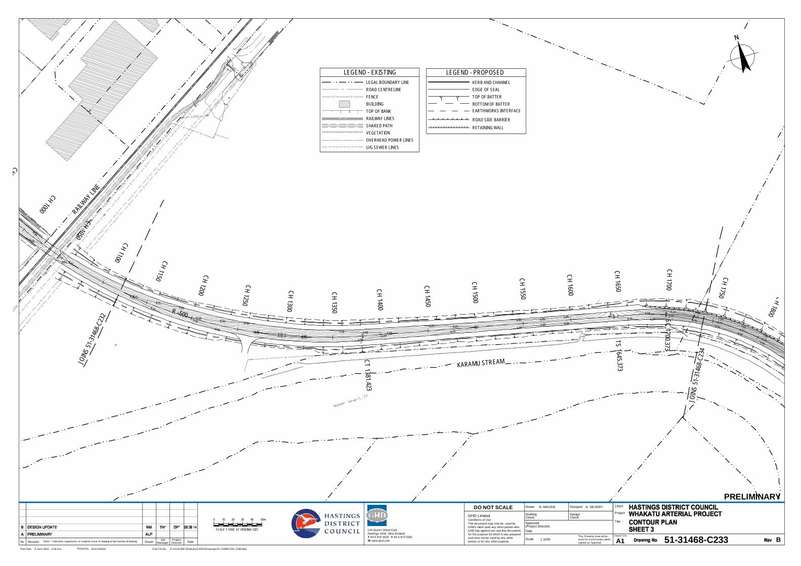
6.00 6.00 6.00
6.006.00 6.00
6.25 6.25
6.25
6.256.256.25
6.25
6.25 6.25 6.256.25
6.256.256.25
6.50
6.50
6.506.50
6.506.50
6.50
6.50
6.50
6.50
6.506.50
6.50
6.506.50
6.506.506.50
6.75
6.75
6.75
6.756.75
6.75 6.75 6.756.756.756.75 7.00
7.00
7.00
7.00
RAILWAY LIN
E
KARAMU STREAMJOIN
S 51
-3146
8-C23
2
JOIN
S 51
-314
68-C
234
||
| | ||
||
||
||
||| |
| || |
| | | | | | | | | | | | | | | | | | | | | | | | | | | | | | | | | | | | | | | | | | | | | | | | | | | | | | | | | | | || |
| |
|
|
|
| | | | | | | | | | | | | | | | | | | | | | | || |
| || |
||
||
||
||
||
|
||
||
||
|
||
||
||
||
||
||
||
||
||
||
|||||||||||||||||||||||||||||
||
|
|||||||||||||||||||||||||||||||||||||||||||||||||||||||||||||||||| ||
E(OH)
E(OH)
E(OH)
E(OH)
E(OH)
E(OH)
E(OH)
E(OH)
E(OH)
E(OH)
E(OH)
E(OH)
E(OH)
E(OH)
S
S
S
S
S
S
S
S
S
S
S
S
S
S
S
S
S
S
S
S
S
S
S
S
S
S
S
S
S
S
S
S
S
S
S
S
S
S
S
S
E(OH)
E(OH)
E(OH)
E(OH)
E(OH)
E(OH)
|
|
|
|
|
|
|
|
|
|
|
|
|
|
|
|
|
|
|
|
|
|
|
|
|
|
|
R -500
CT 1 38 1.42 3
TS 1 64 5.373
SC 1700.373
CH 950
CH 1000
CH 1050
CH 1100 CH 1150 CH 1200
CH 1250
CH 1300
CH 135 0
CH 140 0
CH 145 0
CH 150 0
CH 155 0
CH 160 0
CH 165 0
CH 1700
CH 1750 CH 1800
This Drawing must not beused for Construction unlesssigned as Approved
Date
CheckDrafting
DateDrawnRevisionNo A1Original Size
Title
Project
Client
Check
DesignerDrawn
Scale
DesignConditions of Use.This document may only be used byGHD's client (and any other person whoGHD has agreed can use this document)for the purpose for which it was preparedand must not be used by any otherperson or for any other purpose.
DO NOT SCALE
Note: * indicates signatures on original issue of drawing or last revision of drawing
Plot Date: Cad File No:9 June 2014 - 4:48 p.m. G:\51\31468 Whakatu\CADD\Drawings\51-31468-C231_C235.dwgPlotted by: Nicki Mackie
(Project Director)Approved
JobManager
ProjectDirector
PRELIMINARY
51-31468-C233 B
N. MACKIE N. DEVERY
1:1000
SCALE 1:1000 AT ORIGINAL SIZE
20100 40 50m30
134 Queen Street EastHastings 4156, New ZealandT 64 6 870 9105 F 64 6 873 5281W www.ghd.com
GHD Limited
LEGEND - EXISTING
FENCE
RAILWAY LINES
LEGAL BOUNDARY LINEROAD CENTRELINE
TOP OF BANK
SHARED PATHVEGETATION
BUILDING
OVERHEAD POWER LINESU/G SEWER LINES
E(OH) E(OH) E(OH)
S S S
LEGEND - PROPOSEDKERB AND CHANNEL
TOP OF BATTERBOTTOM OF BATTER
EDGE OF SEAL
ROAD SIDE BARRIER
RETAINING WALL
EARTHWORKS INTERFACE
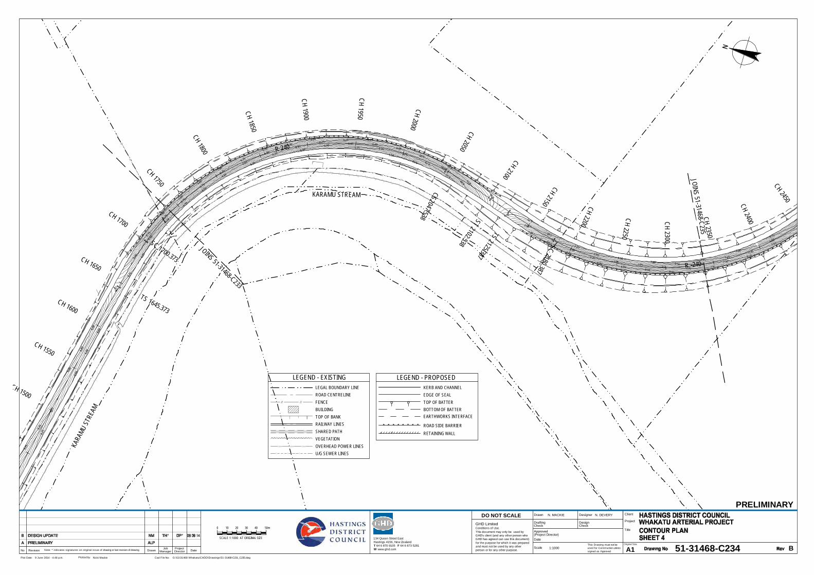
5.50
5.50
5.75
5.75
5.75
5.755.75
6.00
6.00
6.00
6.00
6.00
6.00
6.00
6.00
6.00
6.006.006.00
6.006.00
6.25
6.25
6.25
6.25
6.25
6.25
6.25
6.25
6.25
6.256.25 6.25 6.25
6.25
6.25
6.50
6.50
6.50
6.50
6.50
6.50
6.50
6.50
6.50
6.50
6.50
6.75
6.75
6.75
6.75
6.75
6.75
6.75
6.756.75
6.75
6.75
7.00
7.00
7.00
7.00
7.00
7.00
7.00
7.00
7.00
7.25
7.25
7.25
7.257.25
7.25
7.25
7.50
7.507.507.507.50
7.507.50
7.50
7.50
7.757.757.757.75
7.757.75
7.75
8.008.00
8.00 8.00
KARA
MU ST
REAM
KARAMU STREAM
JOINS 51-31468-C233
JOINS 51-31468- C235
||
||
||
||
||
||
||
||
||
||
||
||
||
||
||
||
||
||
||
||
||
||
||
|| |
|
||
||
||
||
||
||
||
||
||
||
||
|
|
|
|
|
|
||
||
||
||
||
||
||
||
||
||
||
| || | | | | | | | | | | | | | | | | | |
| || |
| || |
||
|
||
||
||
||
||
||
||
||
||
||
||
||
||
||
||
||
||
||
||
||
||
||
||
||
||
||
||
||
||
||
||
||
||
||
||
||
||
||
||
||
||
||
||
||||||||||||||||||||||
||
||
||
||
||
||
||
||
||
||
||
||
|
|
|
|
|
|
||
||
||
||
||
||
||
||
||
||
||
||
||
||
||
||
||
||
||
||
||
||
||
||
||
||
||
||
||
||
||
||
||
||
||
|
TS 1645.373
SC 1700.373
R 240
CS2047.538 ST 2102.538
TS 2125.387
SC 2180.387 R -240
CH 1500
CH 1550
CH 1600
CH 1650
CH 1700
CH 1750
CH 1800
CH 1850
CH 1 900
CH 1950
CH 2000 CH 2050
CH 2100
CH 2150 CH 2200
CH 2250
CH 2 300
CH 2350
CH 2400
CH 2450
This Drawing must not beused for Construction unlesssigned as Approved
Date
CheckDrafting
DateDrawnRevisionNo A1Original Size
Title
Project
Client
Check
DesignerDrawn
Scale
DesignConditions of Use.This document may only be used byGHD's client (and any other person whoGHD has agreed can use this document)for the purpose for which it was preparedand must not be used by any otherperson or for any other purpose.
DO NOT SCALE
Note: * indicates signatures on original issue of drawing or last revision of drawing
Plot Date: Cad File No:9 June 2014 - 4:48 p.m. G:\51\31468 Whakatu\CADD\Drawings\51-31468-C231_C235.dwgPlotted by: Nicki Mackie
(Project Director)Approved
JobManager
ProjectDirector
PRELIMINARY
51-31468-C234 B
N. MACKIE N. DEVERY
1:1000
SCALE 1:1000 AT ORIGINAL SIZE
20100 40 50m30
134 Queen Street EastHastings 4156, New ZealandT 64 6 870 9105 F 64 6 873 5281W www.ghd.com
GHD Limited
LEGEND - EXISTING
FENCE
RAILWAY LINES
LEGAL BOUNDARY LINEROAD CENTRELINE
TOP OF BANK
SHARED PATHVEGETATION
BUILDING
OVERHEAD POWER LINESU/G SEWER LINES
E(OH) E(OH) E(OH)
S S S
LEGEND - PROPOSEDKERB AND CHANNEL
TOP OF BATTERBOTTOM OF BATTER
EDGE OF SEAL
ROAD SIDE BARRIERRETAINING WALL
EARTHWORKS INTERFACE

5.50
5.50
5.755.75
5.755.75
5.755.75
5.75
5.75
6.00
6.00
6.00
6.00
6.006.00
6.006.00
6.00
6.00
6.00
6.00
6.25
6.25
6.25
6.25
6.25
6.25
6.25
6.25
6.25
6.25
6.25
6.50
6.50
6.50
6.50
6.50
6.50
6.50
6.50
6.50
6.50
6.50
6.506.50
6.50
6.50
6.506.50
6.75 6.75
6.75
6.75
6.75
6.75
6.75
6.75
6.75
6.75
6.75
6.75
6.75
6.75
6.75
6.75
6.75
6.756.75
6.75
6. 75
7.007.00
7.00
7.00
7.00
7.00 7.0
0
7.00
7.00
7.007.00
7.00
7.00
7.00
7.00
7.00
7.00
7.00
7.00
7.00
7.00
7.00
7. 00
7 .00
7.25
7.25
7.25
7.25
7.25
7.25
7.25
7.25
7.25
7.25
7.25
7.25
7.25
7.25
7.25
7.25
7.25
7.25
7.25
7.25
7.50
7.50
7.50
7.50
7.50
7.50
7.50
7.50
7.50
7.50
7.50
7.50
7.50
7.50
7.50
7.75
7.75
7.75
7.75
7.75
7.75
7.75
7.75
7.75
7.75
8.00
8.00
8.00
8.00
STAT
E HI
GHW
AY 2
NAPIER ROAD
STATE HIGHWAY 2
JOINS 5
1-314
68-C2
34
||
||
||
||
||
|||
|
||
||
||
||
||
||
||
|
|
||
||
||
||
||
||
||
||
||
||
||
||
||
||
||
||
||
||
||
||
||
||
||
||
||
||
||
E(OH
)
E(OH
)
E(OH
)
E(OH
)
E(OH
)E(
OH)
E(O H
)E(
O H)
E(OH
)E(
OH)
E(OH
)
E(OH
)
E(OH
)
E(OH
)
E(OH
)
E(OH
)
E(OH
)
E(OH
)
E(OH
)
E(OH
)
E(OH
)
E(OH)
E(OH) E(OH) E(OH)
E(OH
)
E(OH
)
E(OH
)
E(OH
)
E(OH
)E(
OH)
E(O H
)E(
O H)
E(OH
)E(
OH)
E(OH
)
E(OH
)
E(OH
)
E(OH
)
E(OH
)
E(OH
)
E(OH
)
E(OH
)
E(OH
)
E(OH
)
E(OH
)
E(OH)
E(OH) E(OH) E(OH)
ST 2102.538
TS 2125.387
SC 2180.387
R -240
CS2477.328
ST 2 53 2 .32 8
2 94 1
CH 2150
CH 2200
CH 2250
CH 2300
CH 2350 CH 2400
CH 2450
CH 2500
CH 2 55 0
CH 2 60 0
CH 2 65 0
CH 2 70 0
CH 2 75 0
CH 2 80 0
CH 2 85 0
CH 2 90 0
0
TC 54.506
R -22
0
CT 168.689
CH 100
CH 150
CH 200
CH 250
R 72
0
CT 223.013
TC 279.132
R -18
0
421
CH 150
CH 200
CH 250
CH 300
CH 350
CH 400
CT 255.000
503
TC 608.462
R 620
CT 740.332
CH 250
CH 300
CH 350
CH 400
CH 450
CH 500
CH 550
CH 600
CH 650
CH 700
CH 750
This Drawing must not beused for Construction unlesssigned as Approved
Date
CheckDrafting
DateDrawnRevisionNo A1Original Size
Title
Project
Client
Check
DesignerDrawn
Scale
DesignConditions of Use.This document may only be used byGHD's client (and any other person whoGHD has agreed can use this document)for the purpose for which it was preparedand must not be used by any otherperson or for any other purpose.
DO NOT SCALE
Note: * indicates signatures on original issue of drawing or last revision of drawing
Plot Date: Cad File No:9 June 2014 - 4:48 p.m. G:\51\31468 Whakatu\CADD\Drawings\51-31468-C231_C235.dwgPlotted by: Nicki Mackie
(Project Director)Approved
JobManager
ProjectDirector
PRELIMINARY
51-31468-C235 B
N. MACKIE N. DEVERY
1:1000
SCALE 1:1000 AT ORIGINAL SIZE
20100 40 50m30
134 Queen Street EastHastings 4156, New ZealandT 64 6 870 9105 F 64 6 873 5281W www.ghd.com
GHD Limited
LEGEND - EXISTING
FENCE
RAILWAY LINES
LEGAL BOUNDARY LINEROAD CENTRELINE
TOP OF BANK
SHARED PATHVEGETATION
BUILDING
OVERHEAD POWER LINESU/G SEWER LINES
E(OH) E(OH) E(OH)
S S S
LEGEND - PROPOSEDKERB AND CHANNEL
TOP OF BATTERBOTTOM OF BATTER
EDGE OF SEAL
ROAD SIDE BARRIER
RETAINING WALL
EARTHWORKS INTERFACE

E(OH)
E(OH) E(OH)
E(OH)
E(OH)E(OH)
E(OH
)
E(O H)E(OH)
E(OH)E(OH)
E(OH)
E(OH)E(OH)
||
||
||
||
||
||
||
||
||
||
||
||
||
||
||
||
||
||
||
||
||
||
||
||
||
||
||
||
||||
||
KARAMU STREAM
RANG
ITANE
ROAD
PAKOWHAI ROAD
PAKOWHAI ROAD
RUAHAPIA ROAD
JOINS 51-31468-C242
0
TC 102. 996
R -900
CT 337.426
CH 50
CH 100
CH 150
CH 200
CH 250
CH 300
CH 350
CH 400
CH 450
CH 500
CH 550
CH 600
0
94
172
298
TS 311.506
SC 366.506
R -35
0
CH 50
CH 100
CH 150
CH 200
CH 250
CH 300
CH 350
CH 400
CH 450
CH 20
CH 260
CH 240
CH 220CH 200
CH 180
CH 160
CH 140
CH 120
CH 100
CH 80
CH 60
CH 40
CH 20
CH 650
This Drawing must not beused for Construction unlesssigned as Approved
Date
CheckDrafting
DateDrawnRevisionNo A1Original Size
Title
Project
Client
Check
DesignerDrawn
Scale
DesignConditions of Use.This document may only be used byGHD's client (and any other person whoGHD has agreed can use this document)for the purpose for which it was preparedand must not be used by any otherperson or for any other purpose.
DO NOT SCALE
Note: * indicates signatures on original issue of drawing or last revision of drawing
Plot Date: Cad File No:9 June 2014 - 4:51 p.m. G:\51\31468 Whakatu\CADD\Drawings\51-31468-C241_C245.dwgPlotted by: Nicki Mackie
(Project Director)Approved
JobManager
ProjectDirector
PRELIMINARY
51-31468-C241 B
N. MACKIE N. DEVERY
1:1000
SCALE 1:1000 AT ORIGINAL SIZE
20100 40 50m30
134 Queen Street EastHastings 4156, New ZealandT 64 6 870 9105 F 64 6 873 5281W www.ghd.com
GHD Limited
LEGEND - EXISTING
FENCE
RAILWAY LINES
LEGAL BOUNDARY LINEROAD CENTRELINE
TOP OF BANK
SHARED PATHVEGETATION
BUILDING
OVERHEAD POWER LINESU/G SEWER LINES
E(OH) E(OH) E(OH)
S S S
LEGEND - PROPOSEDKERB AND CHANNEL
CENTRE LINE
TOP OF BATTERBOTTOM OF BATTER
EDGE LINE
EDGE OF SEAL
ROAD SIDE BARRIER
RETAINING WALL
EARTHWORKS INTERFACE
NO PASSING
DRAINAGE SWALES
DRAINAGE CULVERT/PIPE
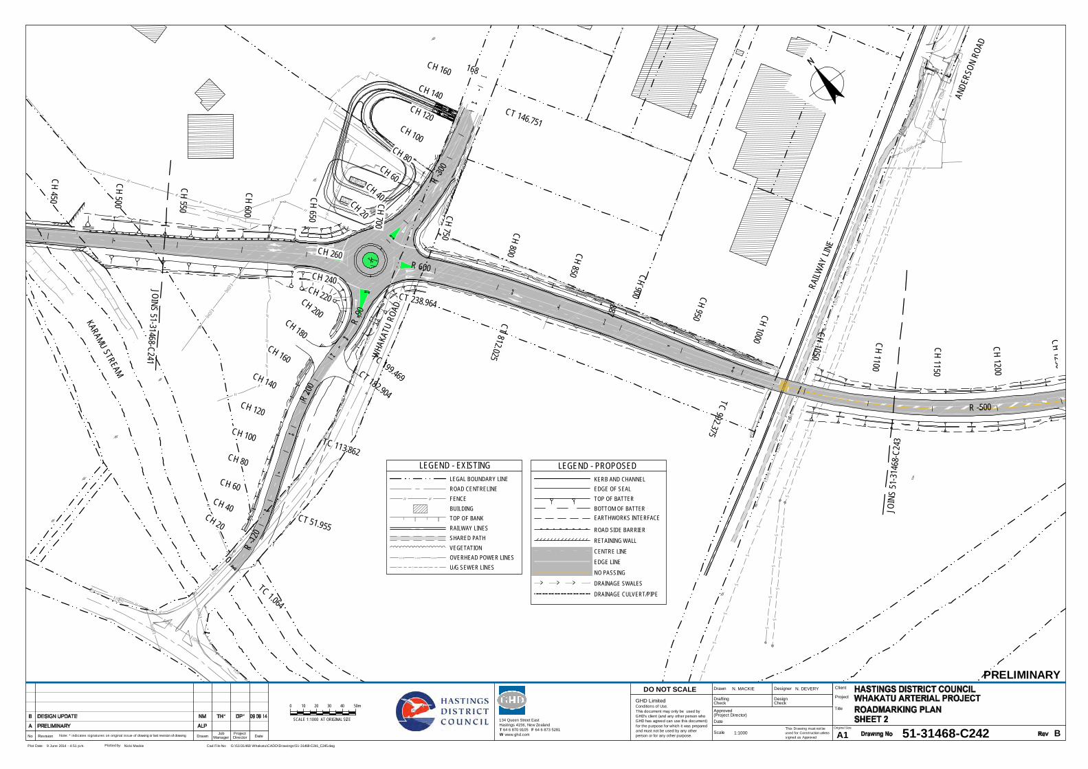
E(OH
)
E(OH
)
E(OH
)
E(OH
)
E(OH
)
E(OH
)
E(OH
)
E(OH
)
E(OH
)
E(OH
)
E(OH
)
E(OH)
E(OH
)
E(OH
)
S
S
S
S
S
S
S
S
S
S
S
S
S
S
S
S
S
S
S
S
S
S
S
S
S
S
S
S
S
SS
SS
S
SS
SS
S
S
S
S
S
S
S
S
S
S
S
S
S
S
S
S
S
S
S
S
S
E(OH
)
E(OH)
E(OH)
E(OH)
E(OH)
E(OH
)
E(OH)
E(OH)
E(OH)
E(OH)
E(OH)
E(OH
)
E(OH
)
E(OH
)
E(OH
)
E(OH
)
E(OH
)
E(OH
)
E(OH
)
E(OH
)
E(OH)
E(OH)
E(OH)
E(OH
)E(
OH)
E(OH
)
E(OH
)
||
|
| ||
||
||
||
||
||
||
||
||
||
||
||
||
||
||
||
||
||
||
||
||
||
|| |
||
||
||
||
|
||
||
||
||
||
||
|
||
||
||
||
||
|
||
||
||
||
||
||
||
||
||
||
||
||
||
||
||
||
||
||
||
||
||
||
||
||
||
||
||
||
||
||
||
||
||
||
||
||
||
||
||
||
||
|
||
||
||
||
||
|
||
||
WHA
KATU
ROA
D
RAILW
AY LI
NE
ANDE
RSON
ROA
D
KARAMU STREAM
JOIN
S 51
-314
68- C
243
JOINS 51-31468-C241
SEMI - T RAILER
SEMI - T RAILER
SEMI - T RAILER
SEMI - T RAILER
R 600
CT 812.025
887
TC 992.375
R -500
CH 450
CH 500
CH 550
CH 600
CH 800 CH 850 CH 900 CH 950 CH 1000
CH 1050
CH 1100
CH 1150
C H 1200
CH 12 50
R -30
0
CT 146.751
168
0
TC 1.064
R -12
0
CT 51.955
TC 113.862
R 20
0
CT 182.904
TC 199.469
R -90
CH 160
CH 140CH 120
CH 100CH 80
CH 60CH 40
CH 20
CH 260
CH 240CH 220CH 200
CH 180CH 160
CH 140
CH 120
CH 100
CH 80
CH 60CH 40
CH 20
CT 238.964
CH 750
CH 700
CH 650
This Drawing must not beused for Construction unlesssigned as Approved
Date
CheckDrafting
DateDrawnRevisionNo A1Original Size
Title
Project
Client
Check
DesignerDrawn
Scale
DesignConditions of Use.This document may only be used byGHD's client (and any other person whoGHD has agreed can use this document)for the purpose for which it was preparedand must not be used by any otherperson or for any other purpose.
DO NOT SCALE
Note: * indicates signatures on original issue of drawing or last revision of drawing
Plot Date: Cad File No:9 June 2014 - 4:51 p.m. G:\51\31468 Whakatu\CADD\Drawings\51-31468-C241_C245.dwgPlotted by: Nicki Mackie
(Project Director)Approved
JobManager
ProjectDirector
PRELIMINARY
51-31468-C242 B
N. MACKIE N. DEVERY
1:1000
SCALE 1:1000 AT ORIGINAL SIZE
20100 40 50m30
134 Queen Street EastHastings 4156, New ZealandT 64 6 870 9105 F 64 6 873 5281W www.ghd.com
GHD Limited
LEGEND - EXISTING
FENCE
RAILWAY LINES
LEGAL BOUNDARY LINEROAD CENTRELINE
TOP OF BANK
SHARED PATHVEGETATION
BUILDING
OVERHEAD POWER LINESU/G SEWER LINES
E(OH) E(OH) E(OH)
S S S
LEGEND - PROPOSEDKERB AND CHANNEL
CENTRE LINE
TOP OF BATTERBOTTOM OF BATTER
EDGE LINE
EDGE OF SEAL
ROAD SIDE BARRIER
RETAINING WALL
EARTHWORKS INTERFACE
NO PASSING
DRAINAGE SWALES
DRAINAGE CULVERT/PIPE

||
| | ||
||
||
||
||| |
| || |
| | | | | | | | | | | | | | | | | | | | | | | | | | | | | | | | | | | | | | | | | | | | | | | | | | | | | | | | | | | || |
| |
|
|
|
| | | | | | | | | | | | | | | | | | | | | | | || |
| || |
||
||
||
||
||
|
||
||
||
|
||
||
||
||
||
||
||
||
||
||
|||||||||||||||||||||||||||||
||
|
|||||||||||||||||||||||||||||||||||||||||||||||||||||||||||||||||| ||
E(OH)
E(OH)
E(OH)
E(OH)
E(OH)
E(OH)
E(OH)
E(OH)
E(OH)
E(OH)
E(OH)
E(OH)
E(OH)
E(OH)
S
S
S
S
S
S
S
S
S
S
S
S
S
S
S
S
S
S
S
S
S
S
S
S
S
S
S
S
S
S
S
S
S
S
S
S
S
S
S
S
S
S
S
S
E(OH)
E(OH)
E(OH)
E(OH)
E(OH)
E(OH)
|
|
|
|
|
|
|
|
|
|
|
|
|
|
|
|
|
|
|
|
|
|
|
|
|
|
|
|
|
|
|
|
|
|
|
|
|
|
|
|
RAILWAY LIN
E
ANDERSON ROAD
KARAMU STREAMJOIN
S 51
-3146
8-C24
2
JOIN
S 51
-314
68-C
244
R -500
CT 1 38 1.42 3
TS 1 64 5.373
SC 1700.373
CH 950
CH 1000
CH 1050
CH 1100 CH 1150 CH 1200
CH 1250
CH 1300
CH 135 0
CH 140 0
CH 145 0
CH 150 0
CH 155 0
CH 160 0
CH 165 0
CH 1700
CH 1750 CH 1800
This Drawing must not beused for Construction unlesssigned as Approved
Date
CheckDrafting
DateDrawnRevisionNo A1Original Size
Title
Project
Client
Check
DesignerDrawn
Scale
DesignConditions of Use.This document may only be used byGHD's client (and any other person whoGHD has agreed can use this document)for the purpose for which it was preparedand must not be used by any otherperson or for any other purpose.
DO NOT SCALE
Note: * indicates signatures on original issue of drawing or last revision of drawing
Plot Date: Cad File No:9 June 2014 - 4:51 p.m. G:\51\31468 Whakatu\CADD\Drawings\51-31468-C241_C245.dwgPlotted by: Nicki Mackie
(Project Director)Approved
JobManager
ProjectDirector
PRELIMINARY
51-31468-C243 B
N. MACKIE N. DEVERY
1:1000
SCALE 1:1000 AT ORIGINAL SIZE
20100 40 50m30
134 Queen Street EastHastings 4156, New ZealandT 64 6 870 9105 F 64 6 873 5281W www.ghd.com
GHD Limited
LEGEND - EXISTING
FENCE
RAILWAY LINES
LEGAL BOUNDARY LINEROAD CENTRELINE
TOP OF BANK
SHARED PATHVEGETATION
BUILDING
OVERHEAD POWER LINESU/G SEWER LINES
E(OH) E(OH) E(OH)
S S S
LEGEND - PROPOSEDKERB AND CHANNEL
CENTRE LINE
TOP OF BATTERBOTTOM OF BATTER
EDGE LINE
EDGE OF SEAL
ROAD SIDE BARRIER
RETAINING WALL
EARTHWORKS INTERFACE
NO PASSING
DRAINAGE SWALES
DRAINAGE CULVERT/PIPE
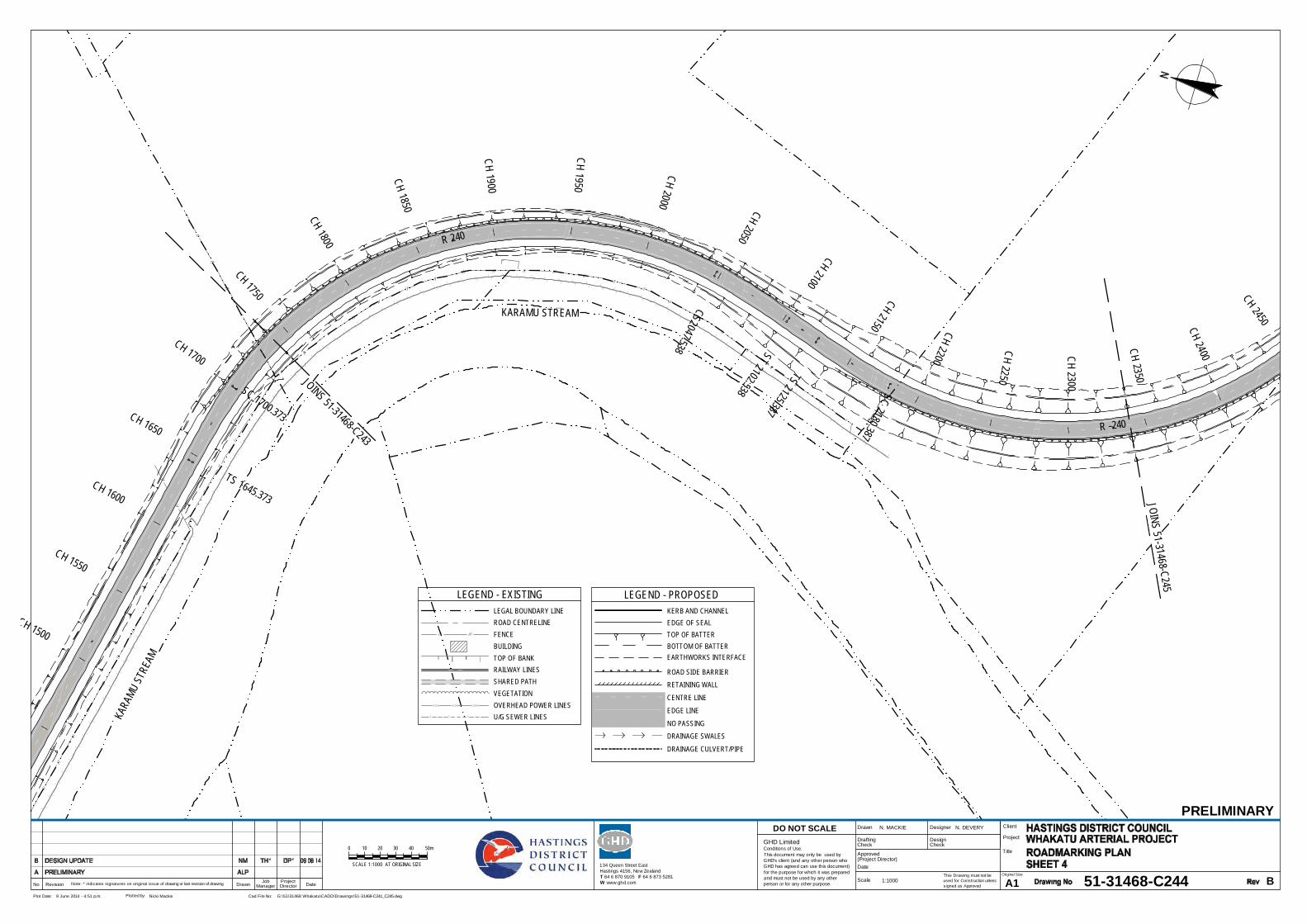
||
||
||
||
||
||
||
||
||
||
||
||
||
||
||
||
||
||
||
||
||
||
||
|| |
|
||
||
||
||
||
||
||
||
||
||
||
|
|
|
|
|
|
||
||
||
||
||
||
||
||
||
||
||
| || | | | | | | | | | | | | | | | | | |
| || |
| || |
||
|
||
||
||
||
||
||
||
||
||
||
||
||
||
||
||
||
||
||
||
||
||
||
||
||
||
||
||
||
||
||
||
||
||
||
||
||
||
||
||
||
||
||
||
||||||||||||||||||||||
||
||
||
||
||
||
||
||
||
||
||
||
|
|
|
|
|
|
||
||
||
||
||
||
||
||
||
||
||
||
||
||
||
||
||
||
||
||
||
||
||
||
||
||
||
||
||
||
||
||
||
||
||
|
KARA
MU ST
REAM
KARAMU STREAM
JOINS 51-31468-C243
JOINS 51-31468- C245
TS 1645.373
SC 1700.373
R 240
CS2047.538 ST 2102.538
TS 2125.387
SC 2180.387 R -240
CH 1500
CH 1550
CH 1600
CH 1650
CH 1700
CH 1750
CH 1800
CH 1850
CH 1 900
CH 1950
CH 2000 CH 2050
CH 2100
CH 2150 CH 2200
CH 2250
CH 2 300
CH 2350
CH 2400
CH 2450
This Drawing must not beused for Construction unlesssigned as Approved
Date
CheckDrafting
DateDrawnRevisionNo A1Original Size
Title
Project
Client
Check
DesignerDrawn
Scale
DesignConditions of Use.This document may only be used byGHD's client (and any other person whoGHD has agreed can use this document)for the purpose for which it was preparedand must not be used by any otherperson or for any other purpose.
DO NOT SCALE
Note: * indicates signatures on original issue of drawing or last revision of drawing
Plot Date: Cad File No:9 June 2014 - 4:51 p.m. G:\51\31468 Whakatu\CADD\Drawings\51-31468-C241_C245.dwgPlotted by: Nicki Mackie
(Project Director)Approved
JobManager
ProjectDirector
PRELIMINARY
51-31468-C244 B
N. MACKIE N. DEVERY
1:1000
SCALE 1:1000 AT ORIGINAL SIZE
20100 40 50m30
134 Queen Street EastHastings 4156, New ZealandT 64 6 870 9105 F 64 6 873 5281W www.ghd.com
GHD Limited
LEGEND - EXISTING
FENCE
RAILWAY LINES
LEGAL BOUNDARY LINEROAD CENTRELINE
TOP OF BANK
SHARED PATHVEGETATION
BUILDING
OVERHEAD POWER LINESU/G SEWER LINES
E(OH) E(OH) E(OH)
S S S
LEGEND - PROPOSEDKERB AND CHANNEL
CENTRE LINE
TOP OF BATTERBOTTOM OF BATTER
EDGE LINE
EDGE OF SEAL
ROAD SIDE BARRIERRETAINING WALL
EARTHWORKS INTERFACE
NO PASSINGDRAINAGE SWALES
DRAINAGE CULVERT/PIPE
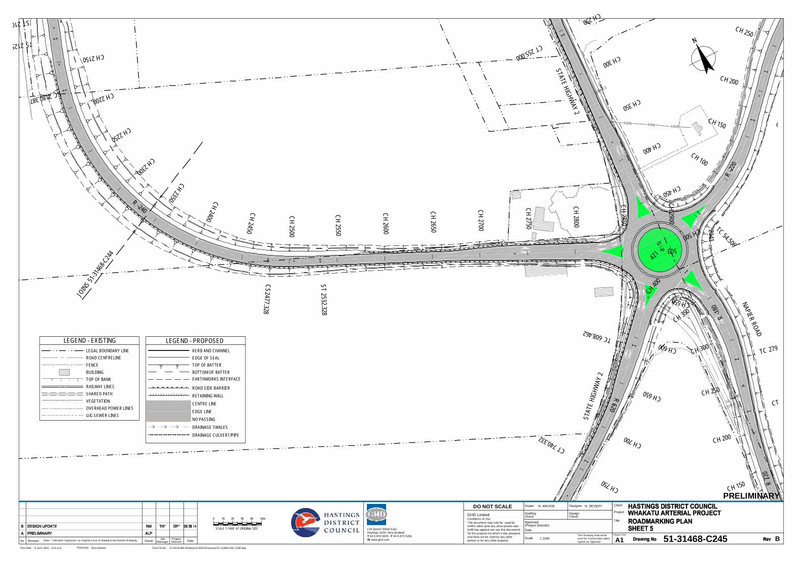
||
||
||
||
||
||
||
||
||
||
||
||
||
||
||
||
||
||
||
||
||
|||
|
||
||
||
||
||
||
||
|
|
||
||
||
||
||
||
||
||
||
||
||
||
||
||
||
||
||
||
||
||
||
|| |
|
||
||
||
||
||
||
||
||
||
||
||
||
||
||
||
||
||
||
||
||
||
||
||
E(OH
)
E(OH
)
E(OH
)
E(OH
)
E(OH
)E(
OH)
E(O H
)E(
O H)
E(OH
)E(
OH)
E(OH
)
E(OH
)
E(OH
)
E(OH
)
E(OH
)
E(OH
)
E(OH
)
E(OH
)
E(OH
)
E(OH
)
E(OH
)
E(OH)
E(OH) E(OH) E(OH)
E(OH
)
E(OH
)
E(OH
)
E(OH
)
E(OH
)E(
OH)
E(O H
)E(
O H)
E(OH
)E(
OH)
E(OH
)
E(OH
)
E(OH
)
E(OH
)
E(OH
)
E(OH
)
E(OH
)
E(OH
)
E(OH
)
E(OH
)
E(OH
)
E(OH)
E(OH) E(OH) E(OH)
STAT
E HI
GHW
AY 2
NAPIER ROAD
STATE HIGHWAY 2
JOINS 5
1-314
68-C2
44
ST 2102.538
TS 2125.387
SC 2180.387
R -240
CS2477.328
ST 2 53 2 .32 8
2 94 1
CH 2150
CH 2200
CH 2250
CH 2300
CH 2350 CH 2400
CH 2450
CH 2500
CH 2 55 0
CH 2 60 0
CH 2 65 0
CH 2 70 0
CH 2 75 0
CH 2 80 0
CH 2 85 0
CH 2 90 0
0
TC 54.506
R -22
0
CT 168.689
CH 100
CH 150
CH 200
CH 250
R 72
0
CT 223.013
TC 279.132
R -18
0
421
CH 150
CH 200
CH 250
CH 300
CH 350
CH 400
CT 255.000
503
TC 608.462
R 620
CT 740.332
CH 250
CH 300
CH 350
CH 400
CH 450
CH 500
CH 550
CH 600
CH 650
CH 700
CH 750
This Drawing must not beused for Construction unlesssigned as Approved
Date
CheckDrafting
DateDrawnRevisionNo A1Original Size
Title
Project
Client
Check
DesignerDrawn
Scale
DesignConditions of Use.This document may only be used byGHD's client (and any other person whoGHD has agreed can use this document)for the purpose for which it was preparedand must not be used by any otherperson or for any other purpose.
DO NOT SCALE
Note: * indicates signatures on original issue of drawing or last revision of drawing
Plot Date: Cad File No:9 June 2014 - 4:51 p.m. G:\51\31468 Whakatu\CADD\Drawings\51-31468-C241_C245.dwgPlotted by: Nicki Mackie
(Project Director)Approved
JobManager
ProjectDirector
PRELIMINARY
51-31468-C245 B
N. MACKIE N. DEVERY
1:1000
SCALE 1:1000 AT ORIGINAL SIZE
20100 40 50m30
134 Queen Street EastHastings 4156, New ZealandT 64 6 870 9105 F 64 6 873 5281W www.ghd.com
GHD Limited
LEGEND - EXISTING
FENCE
RAILWAY LINES
LEGAL BOUNDARY LINEROAD CENTRELINE
TOP OF BANK
SHARED PATHVEGETATION
BUILDING
OVERHEAD POWER LINESU/G SEWER LINES
E(OH) E(OH) E(OH)
S S S
LEGEND - PROPOSEDKERB AND CHANNEL
CENTRE LINE
TOP OF BATTERBOTTOM OF BATTER
EDGE LINE
EDGE OF SEAL
ROAD SIDE BARRIERRETAINING WALL
EARTHWORKS INTERFACE
NO PASSING
DRAINAGE SWALES
DRAINAGE CULVERT/PIPE
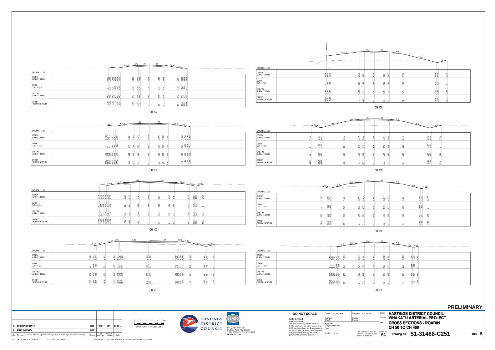
CH 50
1 in 4.2 1 in -4.2 1 in -6.3 -9.5% -2.4% -1.2% -9.5% 1 in -6.31 in -4.2 1 in 4.2
-19.7
75.5
4-0
5.53
8-1
8.68
5.53
-0.25
5.27
8-1
8.06
5.53
-0.25
5.27
8
-14.9
85.5
10.5
16.
017
-11.6
15.4
91.0
76.
555
-10.4
95.4
81.1
76.
651
-10.1
35.4
81.1
16.
585
-10.1
35.4
81.1
16.
585
-0.45
5.53
1.29
6.81
80.5
85.5
31.3
6.83
5
9.28
5.58
1.15
6.72
99.2
85.5
81.1
56.
729
9.63
5.58
1.21
6.79
510
.755.5
91.1
16.
699
14.1
5.60.5
66.
163
18.97
5.6-0
.64.
997
19.6
5.6-0
.64.
997
22.03
5.57
05.
575
OFFSET FROM CENTRELINE
EXISTINGSURFACE LEVEL
DEPTHCUT - / FILL +
DESIGNSURFACE LEVEL
DATUM R.L. 3.00
CH 100
1 in -4 1 in -6-3% -3% 1 in -6 1 in -4 1 in 4
-16.9
65.1
7-0
5.17
4-1
6.39
5.17
0.14
5.31
6-1
5.39
5.17
0.14
5.31
6-1
4.59
5.19
-0.08
5.11
6-1
3.99
5.21
-0.1
5.11
6-1
2.96
5.24
0.13
5.37
3
-7.96
5.40.8
6.20
7
-6.46
5.45
0.86.
252
-3.5
5.55
0.79
6.34
05.6
20.8
36.
445
3.55.6
60.6
86.3
4
75.7
10.5
36.
235
8.55.7
0.49
6.19
13.5
5.65
-0.29
5.35
7
15.34
5.59
-0.69
4.89
715
.945.5
7-0
.674.
897
18.45
5.52
-05.
524
OFFSET FROM CENTRELINE
EXISTINGSURFACE LEVEL
DEPTHCUT - / FILL +
DESIGNSURFACE LEVEL
DATUM R.L. 3.00
CH 150
0% 1 in -6-3% -3% 1 in -6 1 in -4
-14.5
25.1
2-0
5.12
2-1
4.13
5.12
0.15.
217
-13.1
35.1
20.1
5.21
7-1
2.33
5.11
-0.1
5.01
7-1
1.73
5.11
-0.1
5.01
7-1
1.62
5.11
-0.06
5.04
7
-6.62
5.09
0.79
5.88
1
-5.12
5.09
0.84
5.92
6
-3.5
5.08
0.89
5.97
4
05.0
71.0
16.
079
3.55.0
60.9
25.
974
4.95.0
50.8
85.
932
6.45.0
50.8
45.
887
11.4
5.03
0.02
5.05
412
.435.0
3-0
.234.
795
13.03
5.02
-0.23
4.79
513
.945.0
2-0
5.02
2
OFFSET FROM CENTRELINE
EXISTINGSURFACE LEVEL
DEPTHCUT - / FILL +
DESIGNSURFACE LEVEL
DATUM R.L. 3.00
CH 200
1 in -6 -3% -3% -3% 1 in -6 1 in -4
-13.8
24.9
3-0
4.93
5-1
3.08
4.93
0.19
5.11
9-1
2.08
4.93
0.19
5.11
9-1
1.28
4.93
-0.01
4.91
9-1
0.68
4.93
-0.01
4.91
9-1
0.27
4.93
0.09
5.02
2
-5.27
4.94
0.92
5.85
6
-3.77
4.94
0.96
5.90
1-3
.54.9
40.9
75.
909
04.9
51.0
76.
014
3.54.9
50.9
55.
909
54.9
60.9
15.
864
104.9
40.0
95.0
3
11.35
4.93
-0.24
4.69
411
.954.9
3-0
.244.
694
12.88
4.93
04.
928
OFFSET FROM CENTRELINE
EXISTINGSURFACE LEVEL
DEPTHCUT - / FILL +
DESIGNSURFACE LEVEL
DATUM R.L. 3.00
CH 250
1 in -41 in -6
-3% -3% 1 in -61 in -4 1 in 4
-14.8
64.9
10
4.90
7-1
4.41
4.91
0.11
5.02
-13.4
14.9
10.1
15.0
2-1
2.61
4.91
-0.09
4.82
-12.0
14.9
1-0
.094.8
2
-10
4.91
0.41
5.32
3
-54.9
21.2
46.
157
-3.5
4.92
1.28
6.20
2
04.9
21.3
86.
307
3.54.9
31.2
76.
202
54.9
31.2
36.
157
104.9
40.3
95.
323
12.9
4.94
-0.34
4.59
713
.54.9
4-0
.344.
597
14.88
4.94
04.
942
OFFSET FROM CENTRELINE
EXISTINGSURFACE LEVEL
DEPTHCUT - / FILL +
DESIGNSURFACE LEVEL
DATUM R.L. 3.00
CH 300
1 in 4 1 in -41 in -6
-3% -3% 1 in -61 in -4
1 in 4
-17.7
45.2
9-0
5.28
7
-15.4
85.3
5-0
.634.
722
-14.8
85.3
4-0
.624.
722
-10
5.11
0.83
5.94
1
-55.1
41.6
36.
774
-3.5
5.05
1.77
6.81
9
05.0
51.8
86.
924
3.55.0
71.7
56.
819
55.0
71.7
6.77
4
105.0
90.8
55.
941
15.58
5.1-0
.564.
546
16.18
5.1-0
.564.
546
18.43
5.11
05.
109
OFFSET FROM CENTRELINE
EXISTINGSURFACE LEVEL
DEPTHCUT - / FILL +
DESIGNSURFACE LEVEL
DATUM R.L. 3.00
CH 350
1 in 41 in -4
1 in -6-3% -3% 1 in -6
1 in -41 in 4
-21.5
15.4
05.
396
-18.4
95.3
9-0
.744.
643
-17.8
95.3
7-0
.734.
643
-10
5.42
1.26.
616
-55.3
42.1
17.
449
-3.5
5.38
2.12
7.49
4
05.3
12.2
97.
599
3.55.3
72.1
37.
494
55.3
72.0
87.
449
105.3
71.2
56.
616
18.48
5.37
-0.87
4.49
619
.085.3
7-0
.874.
496
22.6
5.38
-05.
376
OFFSET FROM CENTRELINE
EXISTINGSURFACE LEVEL
DEPTHCUT - / FILL +
DESIGNSURFACE LEVEL
DATUM R.L. 3.00
RETA
ININ
G W
ALL
CH 400
1 in -7.9-3% -3% 1 in -6
1 in -41 in 4
-16.3
24.9
60
4.95
6-1
6.34.9
61.6
66.
611
-15.8
24.9
71.6
86.
649
-55.2
22.8
18.
025
-3.5
5.22
2.85
8.07
05.2
12.9
68.
175
3.55.2
12.8
68.0
7
55.2
12.8
28.
025
105.2
1.99
7.19
2
20.98
5.22
-0.78
4.44
621
.585.2
3-0
.784.
446
24.77
5.24
-05.
244
OFFSET FROM CENTRELINE
EXISTINGSURFACE LEVEL
DEPTHCUT - / FILL +
DESIGNSURFACE LEVEL
DATUM R.L. 2.00
This Drawing must not beused for Construction unlesssigned as Approved
Date
CheckDrafting
DateDrawnRevisionNo A1Original Size
Title
Project
Client
Check
DesignerDrawn
Scale
DesignConditions of Use.This document may only be used byGHD's client (and any other person whoGHD has agreed can use this document)for the purpose for which it was preparedand must not be used by any otherperson or for any other purpose.
DO NOT SCALE
Note: * indicates signatures on original issue of drawing or last revision of drawing
Plot Date: Cad File No:9 June 2014 - 4:54 p.m. G:\51\31468 Whakatu\CADD\Drawings\51-31468-C251_C258.dwgPlotted by: Nicki Mackie
(Project Director)Approved
JobManager
ProjectDirector
PRELIMINARY
51-31468-C251 B
N. MACKIE N. DEVERY
1:200
0 2 8 10m64
SCALE 1:200 AT ORIGINAL SIZE 134 Queen Street EastHastings 4156, New ZealandT 64 6 870 9105 F 64 6 873 5281W www.ghd.com
GHD Limited

ROAD
BAR
RIER
CH 500
1 in 41 in -3
-10% -3% -3% 1 in -61 in -4
-18.4
95.7
6-0
5.76
2
-15.9
45.6
9-0
.565.
124
-15.3
45.6
4-0
.525.
124
-75.5
52.3
57.
903
-5.6
5.54
2.58.
043
-5.3
5.56
2.49
8.05
2
-3.5
5.58
2.53
8.10
6
05.5
62.6
58.
211
3.55.5
82.5
38.
106
4.78
5.57
2.58.
068
6.28
5.55
2.47
8.02
3
11.28
5.51.6
87.
189
19.15
5.43
-0.21
5.22
219
.755.4
2-0
.25.
222
20.53
5.42
-05.
417
OFFSET FROM CENTRELINE
EXISTINGSURFACE LEVEL
DEPTHCUT - / FILL +
DESIGNSURFACE LEVEL
DATUM R.L. 3.00
ROAD
BAR
RIER
CH 550
1 in 41 in -3
-10% -3% -3% 1 in -61 in -4
1 in 4
-16.6
5.8-0
5.80
3
-14.2
85.7
7-0
.545.
222
-13.6
85.7
6-0
.545.
222
-75.6
91.7
67.
448
-5.6
5.67
1.91
7.58
8-5
.35.6
71.9
37.
597
-3.5
5.66
27.
651
05.6
22.1
37.
756
3.55.5
92.0
67.
651
5.95
5.56
2.01
7.57
7
7.75
5.55
1.98
7.52
3
12.75
5.51.1
96.6
9
19.52
5.45
-0.45
4.99
820
.125.4
4-0
.454.
998
21.89
5.44
05.4
4
OFFSET FROM CENTRELINE
EXISTINGSURFACE LEVEL
DEPTHCUT - / FILL +
DESIGNSURFACE LEVEL
DATUM R.L. 3.00
ROAD
BAR
RIER
CH 600
1 in 41 in -3
-10% -3% -3% 1 in -61 in -4
-15.7
55.6
40
5.63
9
-14.4
85.6
2-0
.295.
322
-13.8
85.6
1-0
.285.
322
-9.1
5.52
1.39
6.91
5
-7.7
5.51.5
57.
055
-7.4
5.51.5
77.
064
-5.6
5.47
1.65
7.11
8
-3.5
5.43
1.75
7.18
1
05.3
71.9
27.
286
3.55.3
1.89
7.18
1
75.2
31.8
57.
076
8.85.1
91.8
37.
022
13.8
5.03
1.16
6.18
9
19.16
4.86
-0.01
4.84
819
.764.8
6-0
.014.
848
20.56
4.86
0.18
5.04
821
.564.8
70.1
75.
048
22.23
4.88
04.8
8
OFFSET FROM CENTRELINE
EXISTINGSURFACE LEVEL
DEPTHCUT - / FILL +
DESIGNSURFACE LEVEL
DATUM R.L. 3.00
CH 650
1 in 4 1 in -4 1 in -6 1 in -10 -4% -3% -3% 1 in -10 1 in -61 in -4 1 in 3.5
0.6%
-18.5
96.3
90
6.39
1
-15.4
26.4
3-0
.835.
598
-14.8
26.4
4-0
.845.
598
-13.3
96.4
5-0
.55.
955
-10.0
96.5
0.01
6.50
5-8
.996.5
10.1
6.60
5-8
.86.5
10.0
46.
552
-8.64
6.51
0.03
6.54
-8.64
6.51
0.03
6.54
-76.5
30.0
76.
606
-3.5
6.58
0.13
6.71
1
06.6
20.1
96.
816
3.56.6
60.0
56.
711
76.6
9-0
.096.
606
8.86.7
1-0
.166.
552
9.09
6.71
-0.16
6.55
69.0
96.7
1-0
.166.
556
9.44
6.72
-0.1
6.62
110
.546.7
3-0
.216.
521
13.84
6.77
-0.8
5.97
18.94
6.84
-2.14
4.69
819
.546.8
4-2
.154.
697
27.02
6.84
-0.01
6.82
728
.096.8
3-0
6.83
4
OFFSET FROM CENTRELINE
EXISTINGSURFACE LEVEL
DEPTHCUT - / FILL +
DESIGNSURFACE LEVEL
DATUM R.L. 3.00
This Drawing must not beused for Construction unlesssigned as Approved
Date
CheckDrafting
DateDrawnRevisionNo A1Original Size
Title
Project
Client
Check
DesignerDrawn
Scale
DesignConditions of Use.This document may only be used byGHD's client (and any other person whoGHD has agreed can use this document)for the purpose for which it was preparedand must not be used by any otherperson or for any other purpose.
DO NOT SCALE
Note: * indicates signatures on original issue of drawing or last revision of drawing
Plot Date: Cad File No:9 June 2014 - 4:54 p.m. G:\51\31468 Whakatu\CADD\Drawings\51-31468-C251_C258.dwgPlotted by: Nicki Mackie
(Project Director)Approved
JobManager
ProjectDirector
0 2 8 10m64
SCALE 1:200 AT ORIGINAL SIZE 134 Queen Street EastHastings 4156, New ZealandT 64 6 870 9105 F 64 6 873 5281W www.ghd.com
GHD Limited
PRELIMINARY
51-31468-C252 B
N. MACKIE N. DEVERY
1:200

CH 850
1 in -4 1 in -6 -3% -3% 1 in -6
-17.0
45.7
10
5.70
9-1
6.83
5.71
0.05
5.76
3-1
5.83
5.73
0.03
5.76
3-1
5.03
5.74
-0.18
5.56
3-1
4.43
5.75
-0.19
5.56
3
-12.6
85.7
80.2
25.
999
-9.38
5.84
0.71
6.54
9-8
.285.8
50.8
6.64
9-7
.935.8
50.7
36.
584
-7.93
5.85
0.73
6.58
4-6
.185.8
50.7
96.
637
-3.5
5.80.9
26.
717
05.8
30.9
96.
822
3.55.8
70.8
56.
717
75.9
0.71
6.61
2
8.75
5.92
0.64
6.56
8.75
5.92
0.64
6.56
9.15.9
30.7
6.62
510
.25.9
40.5
96.
525
13.5
5.96
0.01
5.97
513
.555.9
60
5.96
2
OFFSET FROM CENTRELINE
EXISTINGSURFACE LEVEL
DEPTHCUT - / FILL +
DESIGNSURFACE LEVEL
DATUM R.L. 4.00
CH 900
1 in -4 1 in -6 -10% -3% -3% -10% 1 in -6
-14.2
35.7
10
5.70
8-1
4.05
5.76
-0.1
5.66
4-1
3.45
5.9-0
.245.
664
-11.5
25.9
20.2
36.
147
-8.22
5.95
0.75
6.69
7-7
.125.9
60.8
46.
797
-6.77
5.96
0.77
6.73
2-6
.775.9
60.7
76.
732
-5.02
5.97
0.81
6.78
5
-3.5
5.99
0.84
6.83
06.0
30.9
6.93
5
3.56.0
90.7
46.8
3
76.1
40.5
86.
725
8.75
6.17
0.56.
673
8.75
6.17
0.56.
673
9.16.1
70.5
66.
738
10.2
6.19
0.45
6.63
8
12.69
6.22
-06.
222
OFFSET FROM CENTRELINE
EXISTINGSURFACE LEVEL
DEPTHCUT - / FILL +
DESIGNSURFACE LEVEL
DATUM R.L. 4.00
CH 950
0% 1 in -4 1 in -6 -10% -3% -3% -3% -10% 1 in -6
-14.3
75.9
3-0
5.93
3-1
4.25
5.86
0.11
5.96
4-1
3.25
5.66
0.35.
964
-12.4
55.8
5-0
.095.
764
-11.8
55.9
1-0
.155.
764
-10.3
55.9
30.2
16.
138
-7.05
5.98
0.71
6.68
8-5
.955.9
90.8
6.78
8-5
.66
0.73
6.72
3-5
.66
0.73
6.72
3-3
.856.0
20.7
66.
775
-3.5
6.02
0.76
6.78
6
06.0
70.8
26.
891
3.56.1
20.6
76.
786
76.1
70.5
16.
681
8.75
6.19
0.44
6.62
88.7
56.1
90.4
46.
628
9.16.1
90.5
6.69
310
.26.2
10.3
86.
593
12.33
6.24
-06.
239
OFFSET FROM CENTRELINE
EXISTINGSURFACE LEVEL
DEPTHCUT - / FILL +
DESIGNSURFACE LEVEL
DATUM R.L. 4.00
CH 1010
1 in -6 -3% -3% -10% 1 in -6
-13.0
75.9
3-0
5.92
6-1
2.44
5.64
0.44
6.08
3-1
1.44
5.72
0.37
6.08
3-1
0.64
5.82
0.06
5.88
3-1
0.04
5.84
0.05
5.88
3-1
05.8
40.0
65.
893
-6.7
5.83
0.61
6.44
3-5
.65.8
40.7
16.
543
-5.25
5.84
0.64
6.47
8-5
.255.8
40.6
46.
478
-3.5
5.85
0.69
6.53
1
05.8
60.7
86.
636
3.55.8
80.6
66.
531
5.25
5.88
0.66.
478
5.25
5.88
0.66.
478
5.65.8
80.6
66.
543
6.75.8
90.5
56.
443
9.94
5.90
5.90
3
OFFSET FROM CENTRELINE
EXISTINGSURFACE LEVEL
DEPTHCUT - / FILL +
DESIGNSURFACE LEVEL
DATUM R.L. 4.00
CH 1045
-3% -1.2% -0.4% -3%
-5.25
5.68
0.54
6.22
-3.5
5.69
0.59
6.27
2
05.7
10.6
6.31
5
3.55.7
50.5
56.
301
5.25
5.77
0.48
6.24
8
OFFSET FROM CENTRELINE
EXISTINGSURFACE LEVEL
DEPTHCUT - / FILL +
DESIGNSURFACE LEVEL
DATUM R.L. 4.00
1 in 4 1 in -4 1 in -6-3% -3% 1 in -6
1 in -4 1 in 4
-15.2
85.5
30
5.53
4
-12.6
15.5
5-0
.694.
867
-12.0
15.5
6-0
.694.
867
-10.5
65.5
7-0
.345.
229
-5.56
5.60.4
76.
063
-4.06
5.60.5
16.
108
-0.56
5.61
0.66.
213
05.6
10.6
16.2
3
3.55.6
20.5
6.12
5
55.6
30.4
56.0
8
105.6
5-0
.45.
246
13.11
5.66
-1.19
4.46
913
.715.6
6-1
.194.
469
18.48
5.66
05.
662
OFFSET FROM CENTRELINE
EXISTINGSURFACE LEVEL
DEPTHCUT - / FILL +
DESIGNSURFACE LEVEL
DATUM R.L. 3.00
This Drawing must not beused for Construction unlesssigned as Approved
Date
CheckDrafting
DateDrawnRevisionNo A1Original Size
Title
Project
Client
Check
DesignerDrawn
Scale
DesignConditions of Use.This document may only be used byGHD's client (and any other person whoGHD has agreed can use this document)for the purpose for which it was preparedand must not be used by any otherperson or for any other purpose.
DO NOT SCALE
Note: * indicates signatures on original issue of drawing or last revision of drawing
Plot Date: Cad File No:9 June 2014 - 4:54 p.m. G:\51\31468 Whakatu\CADD\Drawings\51-31468-C251_C258.dwgPlotted by: Nicki Mackie
(Project Director)Approved
JobManager
ProjectDirector
0 2 8 10m64
SCALE 1:200 AT ORIGINAL SIZE
GHD Limited
PRELIMINARY
51-31468-C253 B
N. MACKIE N. DEVERY
1:200
134 Queen Street EastHastings 4156, New ZealandT 64 6 870 9105 F 64 6 873 5281W www.ghd.com

CH 1500
1 in 4 1 in -6-3% -3% 1 in -6 1 in 4
-14.2
15.9
20
5.91
7
-11.1
25.9
4-0
.795.
145
-10.5
25.9
4-0
.85.
145
-10
5.94
-0.67
5.27
4
-55.9
60.1
46.
108
-3.5
5.97
0.19
6.15
3
05.9
70.2
86.
258
3.55.9
80.1
76.
153
55.9
80.1
36.
108
105.9
8-0
.715.
274
10.58
5.98
-0.85
5.13
11.18
5.98
-0.85
5.13
14.88
6.06
-06.
056
OFFSET FROM CENTRELINE
EXISTINGSURFACE LEVEL
DEPTHCUT - / FILL +
DESIGNSURFACE LEVEL
DATUM R.L. 3.00
CH 1165
1 in 4 1 in -4 1 in -6-3% -3% 1 in -6
1 in -4 1 in 4
-15.6
85.3
90
5.39
4
-14.2
5.4-0
.385.
023
-13.6
5.4-0
.385.
023
-12.3
75.4
1-0
.085.3
3
-7.37
5.43
0.74
6.16
4
-5.87
5.43
0.78
6.20
9
-2.37
5.44
0.87
6.31
4
05.4
50.9
46.
385
3.55.4
60.8
26.2
8
55.4
60.7
86.
235
105.4
7-0
.075.
401
13.04
5.49
-0.84
4.64
113
.645.4
9-0
.854.
641
17.1
5.51
05.
507
OFFSET FROM CENTRELINE
EXISTINGSURFACE LEVEL
DEPTHCUT - / FILL +
DESIGNSURFACE LEVEL
DATUM R.L. 3.00
CH 1200
1 in 4 1 in -4 1 in -6-3% -3% 1 in -6
1 in -4 1 in 4
-16.7
15.4
7-0
5.47
1
-15.1
95.4
7-0
.385.0
9-1
4.59
5.47
-0.38
5.09
-13.1
65.4
8-0
.035.
447
-8.16
5.49
0.79
6.28
-6.66
5.49
0.83
6.32
5
-3.16
5.51
0.92
6.43
05.5
21.0
16.
525
3.55.5
30.8
96.4
2
55.5
30.8
46.
375
105.5
5-0
.015.
541
13.21
5.57
-0.83
4.73
813
.815.5
7-0
.844.
738
17.24
5.6-0
5.59
5
OFFSET FROM CENTRELINE
EXISTINGSURFACE LEVEL
DEPTHCUT - / FILL +
DESIGNSURFACE LEVEL
DATUM R.L. 3.00
CH 1250
1 in 4 1 in -41 in -6
-3% -3% 1 in -6 1 in -4 1 in 4
-19
5.62
05.
621
-16.5
65.6
3-0
.625.0
1-1
5.96
5.63
-0.62
5.01
-13.5
5.64
-0.01
5.62
5
-8.5
5.67
0.79
6.45
9
-75.6
80.8
36.
504
-3.5
5.70.9
6.60
9
05.7
30.9
86.
714
3.55.7
50.8
56.
609
55.7
60.8
6.56
4
105.7
9-0
.065.7
3
11.56
5.8-0
.465.
341
12.16
5.8-0
.465.
341
145.8
05.
802
OFFSET FROM CENTRELINE
EXISTINGSURFACE LEVEL
DEPTHCUT - / FILL +
DESIGNSURFACE LEVEL
DATUM R.L. 3.00
CH 1300
1 in 4 1 in -41 in -6
-3% -3% 1 in -6 1 in -4 1 in 4
-19.1
55.7
3-0
5.73
3
-16.4
55.7
4-0
.685.
059
-15.8
55.7
4-0
.685.
059
-13.2
85.7
4-0
.045.
702
-8.28
5.75
0.78
6.53
5
-6.78
5.75
0.83
6.58
-3.28
5.76
0.92
6.68
5
05.7
61.0
36.
783
3.55.7
80.9
6.67
8
55.7
80.8
56.
633
105.7
90.0
15.8
11.43
5.79
-0.35
5.44
312
.035.8
-0.35
5.44
3
13.45
5.8-0
5.79
9
OFFSET FROM CENTRELINE
EXISTINGSURFACE LEVEL
DEPTHCUT - / FILL +
DESIGNSURFACE LEVEL
DATUM R.L. 3.00
CH 1350
1 in 4 1 in -41 in -6
-3% -3% 1 in -61 in -4 1 in 4
-17.8
45.7
70
5.76
6
-15.2
5.78
-0.67
5.10
7-1
4.65.7
8-0
.675.
107
-12.4
25.7
9-0
.135.
651
-7.42
5.80.6
86.
485
-5.92
5.81
0.72
6.53
-2.42
5.82
0.81
6.63
5
05.8
30.8
86.
707
3.55.8
40.7
66.
602
55.8
40.7
16.
557
105.8
4-0
.115.
724
12.75
5.86
-0.82
5.03
713
.355.8
7-0
.835.
037
16.88
5.92
05.9
2
OFFSET FROM CENTRELINE
EXISTINGSURFACE LEVEL
DEPTHCUT - / FILL +
DESIGNSURFACE LEVEL
DATUM R.L. 3.00
CH 1400
1 in 4 1 in -4 1 in -6-3% -3% 1 in -6 1 in -4 1 in 4
-16.4
35.8
50
5.85
-13.6
55.8
5-0
.695.
156
-13.0
55.8
5-0
.695.
156
-11.5
75.8
5-0
.325.
527
-6.57
5.87
0.49
6.36
-5.07
5.88
0.53
6.40
5
-1.57
5.90.6
16.5
1
05.9
10.6
56.
557
3.55.9
30.5
26.
452
55.9
40.4
66.
407
105.9
7-0
.395.
574
11.9
5.98
-0.88
5.09
912
.55.9
8-0
.885.
099
16.07
5.99
-05.
993
OFFSET FROM CENTRELINE
EXISTINGSURFACE LEVEL
DEPTHCUT - / FILL +
DESIGNSURFACE LEVEL
DATUM R.L. 3.00
CH 1450
1 in 4 1 in -6-3% -3% 1 in -6 1 in 4
-14.8
95.9
05.
903
-12.1
5.91
-0.71
5.20
6-1
1.55.9
1-0
.715.
206
-10.7
25.9
1-0
.515.
403
-5.72
5.91
0.32
6.23
6
-4.22
5.91
0.37
6.28
1
-0.72
5.92
0.47
6.38
60
5.92
0.49
6.40
7
3.55.9
30.3
76.
302
55.9
30.3
26.
257
106.0
1-0
.585.
424
10.9
6.03
-0.83
5.19
911
.56.0
5-0
.855.
199
14.96
6.07
06.
065
OFFSET FROM CENTRELINE
EXISTINGSURFACE LEVEL
DEPTHCUT - / FILL +
DESIGNSURFACE LEVEL
DATUM R.L. 3.00
This Drawing must not beused for Construction unlesssigned as Approved
Date
CheckDrafting
DateDrawnRevisionNo A1Original Size
Title
Project
Client
Check
DesignerDrawn
Scale
DesignConditions of Use.This document may only be used byGHD's client (and any other person whoGHD has agreed can use this document)for the purpose for which it was preparedand must not be used by any otherperson or for any other purpose.
DO NOT SCALE
Note: * indicates signatures on original issue of drawing or last revision of drawing
Plot Date: Cad File No:9 June 2014 - 4:54 p.m. G:\51\31468 Whakatu\CADD\Drawings\51-31468-C251_C258.dwgPlotted by: Nicki Mackie
(Project Director)Approved
JobManager
ProjectDirector
0 2 8 10m64
SCALE 1:200 AT ORIGINAL SIZE 134 Queen Street EastHastings 4156, New ZealandT 64 6 870 9105 F 64 6 873 5281W www.ghd.com
GHD Limited
PRELIMINARY
51-31468-C254 B
N. MACKIE N. DEVERY
1:200

CH 1550
1 in 4 1 in -6-3% -3% 1 in -6 1 in 4
-13.8
15.7
60
5.76
2
-10.9
45.7
5-0
.715.
045
-10.3
45.7
5-0
.715.
045
-10
5.76
-0.63
5.13
-55.7
70.2
5.96
3
-3.5
5.77
0.24
6.00
8
05.7
80.3
46.
113
3.55.7
80.2
36.
008
55.7
80.1
85.
963
105.7
9-0
.665.1
310
.25.8
-0.72
5.08
10.8
5.82
-0.74
5.08
14.2
5.93
05.
931
OFFSET FROM CENTRELINE
EXISTINGSURFACE LEVEL
DEPTHCUT - / FILL +
DESIGNSURFACE LEVEL
DATUM R.L. 3.00
CH 1600
1 in 4 1 in -6-3% -3% 1 in -6 1 in 4
-13.4
5.46
05.
463
-11.3
25.4
6-0
.524.
945
-10.7
25.4
6-0
.524.
945
-10
5.46
-0.34
5.12
6
-55.4
80.4
85.
959
-3.5
5.49
0.51
6.00
4
05.5
20.5
96.
109
3.55.5
40.4
76.
004
55.5
50.4
15.
959
105.5
8-0
.455.
126
10.38
5.58
-0.55
5.03
10.98
5.59
-0.56
5.03
13.27
5.60
5.60
2
OFFSET FROM CENTRELINE
EXISTINGSURFACE LEVEL
DEPTHCUT - / FILL +
DESIGNSURFACE LEVEL
DATUM R.L. 3.00
CH 1650
1 in 4 1 in -41 in -6 0.5% -3% 1 in -6 1 in -4 1 in 4
-15.1
85.3
30
5.32
8
-13.2
55.3
2-0
.474.
845
-12.6
55.3
1-0
.474.
845
-10.0
65.2
80.2
25.
492
-5.06
5.27
1.06
6.32
6
-3.56
5.27
1.05
6.31
8
05.2
71.0
36.3
3.56
5.26
0.93
6.19
3
5.06
5.26
0.89
6.14
8
10.06
5.21
0.15.
315
11.57
5.2-0
.264.
938
12.17
5.19
-0.25
4.93
8
13.6
5.30
5.29
5
OFFSET FROM CENTRELINE
EXISTINGSURFACE LEVEL
DEPTHCUT - / FILL +
DESIGNSURFACE LEVEL
DATUM R.L. 3.00 RO
AD B
ARRI
ER
CH 1700
1 in 41 in -3
-10% 6% -6%1 in -6 1 in -4 1 in 4
-15.7
95.1
20
5.12
3
-14.2
75.0
9-0
.354.
741
-13.6
75.0
8-0
.344.
741
-7.7
5.17
1.56
6.73
2
-6.3
5.18
1.69
6.87
2-5
.75.1
81.7
16.8
9
-4.2
5.18
1.62
6.8
05.1
81.3
76.5
5
4.25.2
1.16.3
5.75.2
11
6.21
1
10.7
5.23
0.15
5.37
7
12.84
5.23
-0.39
4.84
113
.445.2
2-0
.384.
841
14.95
5.22
05.
219
OFFSET FROM CENTRELINE
EXISTINGSURFACE LEVEL
DEPTHCUT - / FILL +
DESIGNSURFACE LEVEL
DATUM R.L. 3.00
ROAD
BAR
RIER
CH 1750
1 in 41 in -3
-10% 6% -6%1 in -6
1 in -4 1 in 4
-17.5
5.28
05.
278
-15.0
95.2
9-0
.614.
674
-14.4
95.2
9-0
.614.
674
-7.7
5.23
1.71
6.93
6
-6.3
5.21
1.86
7.07
6-5
.75.2
11.8
97.
094
-4.2
5.19
1.81
7.00
4
05.1
51.6
6.75
2
4.25.1
11.3
96.5
5.75.1
11.3
6.41
10.7
5.10.4
85.
577
14.55
5.09
-0.47
4.61
415
.155.0
9-0
.474.
614
17.02
5.08
-05.
082
OFFSET FROM CENTRELINE
EXISTINGSURFACE LEVEL
DEPTHCUT - / FILL +
DESIGNSURFACE LEVEL
DATUM R.L. 3.00
ROAD
BAR
RIER
CH 1800
1 in 41 in -3
-10% 6% -6%1 in -6
1 in -4 1 in 4
-16.9
45.2
9-0
5.28
5
-14.7
85.2
7-0
.534.
745
-14.1
85.2
7-0
.524.
745
-7.7
5.22
1.68
6.90
6
-6.3
5.22
1.83
7.04
6-5
.75.2
11.8
57.
064
-4.2
5.21.7
76.
974
05.1
71.5
56.
722
4.25.1
51.3
26.4
7
5.75.1
41.2
46.3
8
10.7
5.08
0.47
5.54
7
14.21
5.03
-0.37
4.66
814
.815.0
3-0
.364.
668
16.21
5.02
-05.
017
OFFSET FROM CENTRELINE
EXISTINGSURFACE LEVEL
DEPTHCUT - / FILL +
DESIGNSURFACE LEVEL
DATUM R.L. 3.00
ROAD
BAR
RIER
CH 1850
1 in 41 in -3
-10% 6% -6%1 in -6 1 in -4 1 in 4
-15.5
35.2
90
5.29
-13.7
75.2
9-0
.444.
851
-13.1
75.2
9-0
.444.
851
-7.7
5.29
1.38
6.67
4
-6.3
5.29
1.52
6.81
4-5
.75.2
91.5
46.
832
-4.2
5.28
1.46
6.74
2
05.2
71.2
26.4
9
4.25.2
41
6.23
8
5.75.2
30.9
26.
148
10.7
5.16
0.15
5.31
5
13.1
5.13
-0.41
4.71
513
.75.1
2-0
.414.
715
15.24
5.10
5.10
1
OFFSET FROM CENTRELINE
EXISTINGSURFACE LEVEL
DEPTHCUT - / FILL +
DESIGNSURFACE LEVEL
DATUM R.L. 3.00
ROAD
BAR
RIER
CH 1900
1 in 4 1 in -31 in -10 6% -6% 1 in -6 1 in -4 1 in 4
-13.9
85.2
8-0
5.27
5
-12.7
5.27
-0.32
4.95
6-1
2.15.2
7-0
.324.
956
-7.7
5.27
1.15
6.42
4
-6.3
5.27
1.36.
564
-5.7
5.27
1.31
6.58
2
-4.2
5.28
1.22
6.49
2
05.2
90.9
56.2
4
4.25.3
10.6
85.
988
5.75.3
10.5
85.
898
10.7
5.33
-0.27
5.06
5
11.99
5.34
-0.6
4.74
212
.595.3
4-0
.64.
742
15.03
5.35
05.3
5
OFFSET FROM CENTRELINE
EXISTINGSURFACE LEVEL
DEPTHCUT - / FILL +
DESIGNSURFACE LEVEL
DATUM R.L. 3.00
This Drawing must not beused for Construction unlesssigned as Approved
Date
CheckDrafting
DateDrawnRevisionNo A1Original Size
Title
Project
Client
Check
DesignerDrawn
Scale
DesignConditions of Use.This document may only be used byGHD's client (and any other person whoGHD has agreed can use this document)for the purpose for which it was preparedand must not be used by any otherperson or for any other purpose.
DO NOT SCALE
Note: * indicates signatures on original issue of drawing or last revision of drawing
Plot Date: Cad File No:9 June 2014 - 4:55 p.m. G:\51\31468 Whakatu\CADD\Drawings\51-31468-C251_C258.dwgPlotted by: Nicki Mackie
(Project Director)Approved
JobManager
ProjectDirector
0 2 8 10m64
SCALE 1:200 AT ORIGINAL SIZE 134 Queen Street EastHastings 4156, New ZealandT 64 6 870 9105 F 64 6 873 5281W www.ghd.com
GHD Limited
PRELIMINARY
51-31468-C255 B
N. MACKIE N. DEVERY
1:200
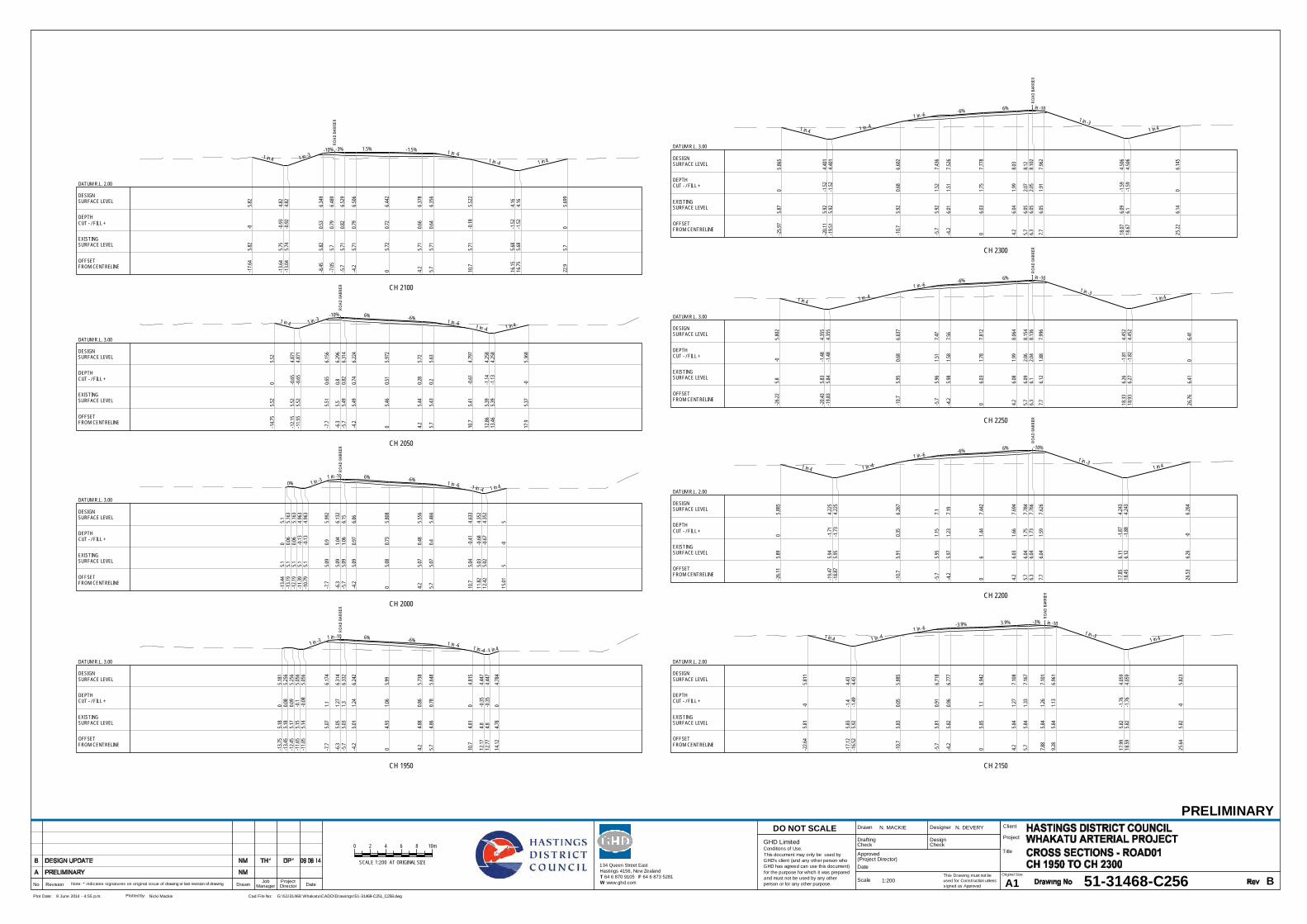
ROAD
BAR
RIER
CH 1950
1 in -31 in -10 6% -6% 1 in -6 1 in -4 1 in 4
-13.7
55.1
80
5.18
1-1
3.45
5.18
0.08
5.25
6-1
2.45
5.17
0.09
5.25
6-1
1.65
5.15
-0.1
5.05
6-1
1.05
5.14
-0.08
5.05
6
-7.7
5.07
1.16.
174
-6.3
5.05
1.27
6.31
4-5
.75.0
31.3
6.33
2
-4.2
5.01
1.24
6.24
2
04.9
31.0
65.9
9
4.24.8
80.8
65.
738
5.74.8
60.7
85.
648
10.7
4.81
04.
815
12.17
4.8-0
.354.
447
12.77
4.8-0
.354.
447
14.12
4.78
04.
784
OFFSET FROM CENTRELINE
EXISTINGSURFACE LEVEL
DEPTHCUT - / FILL +
DESIGNSURFACE LEVEL
DATUM R.L. 3.00
ROAD
BAR
RIER
CH 2000
0% 1 in -31 in -10 6% -6%
1 in -6 1 in -4 1 in 4
-13.4
45.1
05.1
-13.1
95.1
0.06
5.16
3-1
2.19
5.10.0
65.
163
-11.3
95.1
-0.13
4.96
3-1
0.79
5.1-0
.134.
963
-7.7
5.09
0.95.
992
-6.3
5.09
1.04
6.13
2-5
.75.0
91.0
66.1
5
-4.2
5.09
0.97
6.06
05.0
80.7
35.
808
4.25.0
70.4
85.
556
5.75.0
70.4
5.46
6
10.7
5.04
-0.41
4.63
311
.825.0
3-0
.684.
352
12.42
5.02
-0.67
4.35
2
15.01
5-0
5
OFFSET FROM CENTRELINE
EXISTINGSURFACE LEVEL
DEPTHCUT - / FILL +
DESIGNSURFACE LEVEL
DATUM R.L. 3.00
ROAD
BAR
RIER
CH 2050
1 in 4 1 in -3-10% 6% -6% 1 in -6 1 in -4 1 in 4
-14.7
55.5
20
5.52
-12.1
55.5
2-0
.654.
871
-11.5
55.5
2-0
.654.
871
-7.7
5.51
0.65
6.15
6
-6.3
5.50.8
6.29
6-5
.75.4
90.8
26.
314
-4.2
5.49
0.74
6.22
4
05.4
60.5
15.
972
4.25.4
40.2
85.7
2
5.75.4
30.2
5.63
10.7
5.41
-0.61
4.79
7
12.86
5.39
-1.14
4.25
813
.465.3
9-1
.134.
258
17.9
5.37
-05.
368
OFFSET FROM CENTRELINE
EXISTINGSURFACE LEVEL
DEPTHCUT - / FILL +
DESIGNSURFACE LEVEL
DATUM R.L. 3.00 RO
AD B
ARRI
ER
CH 2100
1 in 4 1 in -3-10% -3% 1.5% -1.5% 1 in -6
1 in -4 1 in 4
-17.6
45.8
2-0
5.82
-13.6
45.7
5-0
.934.8
2-1
3.04
5.74
-0.92
4.82
-8.45
5.82
0.53
6.34
9
-7.05
5.70.7
96.
489
-5.7
5.71
0.82
6.52
9
-4.2
5.71
0.79
6.50
6
05.7
20.7
26.
442
4.25.7
10.6
66.
378
5.75.7
10.6
46.
356
10.7
5.71
-0.18
5.52
2
16.15
5.68
-1.52
4.16
16.75
5.68
-1.52
4.16
22.9
5.70
5.69
9
OFFSET FROM CENTRELINE
EXISTINGSURFACE LEVEL
DEPTHCUT - / FILL +
DESIGNSURFACE LEVEL
DATUM R.L. 2.00
ROAD
BAR
RIER
CH 2150
1 in 4 1 in -41 in -6
-3.9% 3.9% -3% 1 in -10
1 in -31 in 4
-22.6
45.8
1-0
5.81
1
-17.1
25.8
3-1
.44.4
3-1
6.52
5.92
-1.49
4.43
-10.7
5.83
0.05
5.88
5
-5.7
5.81
0.91
6.71
8
-4.2
5.82
0.96
6.77
7
05.8
51.1
6.94
2
4.25.8
41.2
77.
108
5.75.8
41.3
37.
167
7.88
5.84
1.26
7.10
1
9.28
5.84
1.13
6.96
1
17.99
5.82
-1.76
4.05
918
.595.8
2-1
.764.
059
25.64
5.82
-05.
823
OFFSET FROM CENTRELINE
EXISTINGSURFACE LEVEL
DEPTHCUT - / FILL +
DESIGNSURFACE LEVEL
DATUM R.L. 2.00
ROAD
BAR
RIER
CH 2200
1 in 4 1 in -4
1 in -6-6% 6% -10%
1 in -31 in 4
-26.1
15.8
90
5.88
5
-19.4
75.9
4-1
.714.
225
-18.8
75.9
5-1
.734.
225
-10.7
5.91
0.35
6.26
7
-5.7
5.95
1.15
7.1
-4.2
5.97
1.23
7.19
06
1.44
7.44
2
4.26.0
31.6
67.
694
5.76.0
41.7
57.
784
6.36.0
41.7
37.
766
7.76.0
41.5
97.
626
17.85
6.11
-1.87
4.24
318
.456.1
2-1
.884.
243
26.53
6.26
-06.
264
OFFSET FROM CENTRELINE
EXISTINGSURFACE LEVEL
DEPTHCUT - / FILL +
DESIGNSURFACE LEVEL
DATUM R.L. 2.00
ROAD
BAR
RIER
CH 2250
1 in 4 1 in -4
1 in -6-6% 6% 1 in -10
1 in -31 in 4
-26.2
25.8
-05.
802
-20.4
35.8
3-1
.484.
355
-19.8
35.8
4-1
.484.
355
-10.7
5.95
0.68
6.63
7
-5.7
5.96
1.51
7.47
-4.2
5.98
1.58
7.56
06.0
31.7
87.
812
4.26.0
81.9
98.
064
5.76.0
92.0
68.
154
6.36.1
2.04
8.13
6
7.76.1
21.8
87.
996
18.33
6.26
-1.81
4.45
218
.936.2
7-1
.824.
452
26.76
6.41
06.4
1
OFFSET FROM CENTRELINE
EXISTINGSURFACE LEVEL
DEPTHCUT - / FILL +
DESIGNSURFACE LEVEL
DATUM R.L. 3.00
ROAD
BAR
RIER
CH 2300
1 in 4 1 in -4
1 in -6-6% 6% 1 in -10
1 in -31 in 4
-25.9
75.8
70
5.86
5
-20.1
15.9
2-1
.524.
401
-19.5
15.9
2-1
.524.
401
-10.7
5.92
0.68
6.60
2
-5.7
5.92
1.52
7.43
6
-4.2
6.01
1.51
7.52
6
06.0
31.7
57.
778
4.26.0
41.9
98.0
3
5.76.0
52.0
78.1
26.3
6.05
2.05
8.10
2
7.76.0
51.9
17.
962
18.07
6.09
-1.59
4.50
618
.676.1
-1.59
4.50
6
25.22
6.14
06.
145
OFFSET FROM CENTRELINE
EXISTINGSURFACE LEVEL
DEPTHCUT - / FILL +
DESIGNSURFACE LEVEL
DATUM R.L. 3.00
This Drawing must not beused for Construction unlesssigned as Approved
Date
CheckDrafting
DateDrawnRevisionNo A1Original Size
Title
Project
Client
Check
DesignerDrawn
Scale
DesignConditions of Use.This document may only be used byGHD's client (and any other person whoGHD has agreed can use this document)for the purpose for which it was preparedand must not be used by any otherperson or for any other purpose.
DO NOT SCALE
Note: * indicates signatures on original issue of drawing or last revision of drawing
Plot Date: Cad File No:9 June 2014 - 4:55 p.m. G:\51\31468 Whakatu\CADD\Drawings\51-31468-C251_C258.dwgPlotted by: Nicki Mackie
(Project Director)Approved
JobManager
ProjectDirector
0 2 8 10m64
SCALE 1:200 AT ORIGINAL SIZE 134 Queen Street EastHastings 4156, New ZealandT 64 6 870 9105 F 64 6 873 5281W www.ghd.com
GHD Limited
PRELIMINARY
51-31468-C256 B
N. MACKIE N. DEVERY
1:200

ROAD
BAR
RIER
CH 2350
1 in 4 1 in -41 in -6
-6% 6% -10%
1 in -31 in 4
-24.4
85.9
-05.
903
-18.6
65.7
8-1
.334.
447
-18.0
65.8
3-1
.384.
447
-10.7
5.78
0.51
6.28
6
-5.7
5.81
1.31
7.11
9
-4.2
5.82
1.39
7.20
9
05.8
51.6
17.
461
4.25.8
81.8
37.
713
5.75.8
91.9
17.
803
6.35.8
91.8
97.
785
7.75.9
1.74
7.64
5
16.96
5.94
-1.38
4.56
17.56
5.94
-1.38
4.56
23.1
5.95
-05.
947
OFFSET FROM CENTRELINE
EXISTINGSURFACE LEVEL
DEPTHCUT - / FILL +
DESIGNSURFACE LEVEL
DATUM R.L. 3.00
ROAD
BAR
RIER
CH 2400
1 in 4 1 in -41 in -6
-6% 6% 1 in -101 in -3
1 in 4
-22.2
15.7
50
5.75
2
-17.1
75.6
8-1
.184.
493
-16.5
75.6
8-1
.194.
493
-10.7
5.69
0.27
5.96
1
-5.7
5.71.1
6.79
4
-4.2
5.71.1
96.
884
05.6
91.4
47.
136
4.25.6
91.7
7.38
8
5.75.6
81.7
97.
478
6.35.6
81.7
87.4
6
7.75.6
81.6
47.3
2
15.82
5.71
-1.1
4.61
316
.425.7
2-1
.114.
613
215.7
60
5.75
7
OFFSET FROM CENTRELINE
EXISTINGSURFACE LEVEL
DEPTHCUT - / FILL +
DESIGNSURFACE LEVEL
DATUM R.L. 3.00
ROAD
BAR
RIER
CH 2450
1 in 4 1 in -41 in -6
-6% 6% 1 in -101 in -3
1 in 4
-18.5
5.24
05.
243
-15.6
95.2
4-0
.74.
539
-15.0
95.2
4-0
.74.
539
-10.7
5.23
0.41
5.63
6
-5.7
5.22
1.25
6.46
9
-4.2
5.21
1.35
6.55
9
05.1
91.6
26.
811
4.25.1
81.8
97.
063
5.75.2
1.95
7.15
36.3
5.22
1.92
7.13
5
7.75.2
61.7
36.
995
14.69
5.29
-0.62
4.66
615
.295.2
9-0
.624.
666
17.68
5.26
05.
264
OFFSET FROM CENTRELINE
EXISTINGSURFACE LEVEL
DEPTHCUT - / FILL +
DESIGNSURFACE LEVEL
DATUM R.L. 3.00
ROAD
BAR
RIER
CH 2500
1 in 4 1 in -41 in -6
-3.5% 3.5% -10%1 in -3
1 in 4
-17.4
75.3
3-0
5.32
6
-14.5
15.3
1-0
.734.
587
-13.9
15.3
1-0
.724.
587
-10.4
15.2
90.1
75.
462
-5.41
5.26
1.03
6.29
5
-3.91
5.25
1.09
6.34
8
05.2
81.2
16.
486
3.91
5.35
1.27
6.62
4
5.41
5.36
1.32
6.67
76.0
15.3
61.3
6.65
9
7.41
5.36
1.16
6.51
9
12.81
5.35
-0.64
4.71
913
.415.3
5-0
.644.
719
15.95
5.35
05.
352
OFFSET FROM CENTRELINE
EXISTINGSURFACE LEVEL
DEPTHCUT - / FILL +
DESIGNSURFACE LEVEL
DATUM R.L. 3.00
ROAD
BAR
RIER
CH 2550
1 in 4 1 in -41 in -6
-3% -1.9% 1 in -10 1 in -3 1 in 4
-15.1
85.2
40
5.24
-12.7
75.2
7-0
.634.
636
-12.1
75.2
7-0
.644.
636
-10
5.33
-0.15
5.17
8
-55.4
0.61
6.01
1
-3.5
5.44
0.62
6.05
6
05.4
30.7
36.
161
3.55.4
30.6
66.
094
55.4
30.6
36.
065
5.65.4
30.6
26.
047
75.4
30.4
85.
907
10.41
5.43
-0.66
4.76
911
.015.4
3-0
.664.
769
13.66
5.43
-05.
431
OFFSET FROM CENTRELINE
EXISTINGSURFACE LEVEL
DEPTHCUT - / FILL +
DESIGNSURFACE LEVEL
DATUM R.L. 3.00
ROAD
BAR
RIER
ROAD
BAR
RIER
CH 2600
1 in 4 1 in -3 -10% -3% -3% 1 in -10 1 in -3 1 in 4
-12.9
85.3
80
5.38
1
-10.3
15.4
-0.68
4.71
5-9
.715.4
-0.69
4.71
5
-75.4
50.1
75.6
2
-5.6
5.48
0.28
5.76
-55.4
80.3
5.77
8
-3.5
5.49
0.34
5.82
3
05.4
80.4
55.
928
3.55.4
60.3
65.
823
55.4
60.3
25.
778
5.65.4
60.3
5.76
75.4
70.1
55.6
2
9.35.4
7-0
.624.
854
9.95.4
7-0
.624.
854
12.39
5.48
05.
478
OFFSET FROM CENTRELINE
EXISTINGSURFACE LEVEL
DEPTHCUT - / FILL +
DESIGNSURFACE LEVEL
DATUM R.L. 3.00
ROAD
BAR
RIER
ROAD
BAR
RIER
CH 2650
1 in 4 1 in -3 -10% -3% -3% 1 in -101 in -3 1 in 4
-12.2
95.4
30
5.42
6
-9.85
5.48
-0.67
4.81
5-9
.255.5
-0.68
4.81
5
-75.5
30.0
35.
564
-5.6
5.55
0.16
5.70
4-5
5.55
0.17
5.72
2
-3.5
5.56
0.21
5.76
7
05.5
70.3
15.
872
3.55.5
70.2
5.76
7
55.5
60.1
65.
722
5.65.5
60.1
45.
704
75.5
6-0
5.56
4
8.93
5.56
-0.64
4.92
29.5
35.5
6-0
.644.
922
12.08
5.56
05.5
6
OFFSET FROM CENTRELINE
EXISTINGSURFACE LEVEL
DEPTHCUT - / FILL +
DESIGNSURFACE LEVEL
DATUM R.L. 3.00
ROAD
BAR
RIER
ROAD
BAR
RIER
CH 2700
1 in 4 1 in -3 -10% -3% -3% -3% -10% 1 in -3 1 in 4
-13.8
55.4
5-0
5.44
8
-11.7
25.4
7-0
.564.
915
-11.1
25.4
8-0
.564.
915
-9.1
5.49
0.09
5.58
8
-7.7
5.50.2
35.
728
-7.1
5.51
0.24
5.74
6
-5.6
5.51
0.28
5.79
1
-3.5
5.53
0.33
5.85
4
05.5
40.4
15.
959
3.55.5
50.3
15.
854
4.17
5.54
0.29
5.83
3
5.67
5.54
0.25
5.78
86.2
75.5
40.2
35.7
7
7.67
5.53
0.15.6
3
9.45.5
3-0
.475.
054
105.5
2-0
.475.
054
11.85
5.52
05.
515
OFFSET FROM CENTRELINE
EXISTINGSURFACE LEVEL
DEPTHCUT - / FILL +
DESIGNSURFACE LEVEL
DATUM R.L. 3.00
This Drawing must not beused for Construction unlesssigned as Approved
Date
CheckDrafting
DateDrawnRevisionNo A1Original Size
Title
Project
Client
Check
DesignerDrawn
Scale
DesignConditions of Use.This document may only be used byGHD's client (and any other person whoGHD has agreed can use this document)for the purpose for which it was preparedand must not be used by any otherperson or for any other purpose.
DO NOT SCALE
Note: * indicates signatures on original issue of drawing or last revision of drawing
Plot Date: Cad File No:9 June 2014 - 4:55 p.m. G:\51\31468 Whakatu\CADD\Drawings\51-31468-C251_C258.dwgPlotted by: Nicki Mackie
(Project Director)Approved
JobManager
ProjectDirector
0 2 8 10m64
SCALE 1:200 AT ORIGINAL SIZE 134 Queen Street EastHastings 4156, New ZealandT 64 6 870 9105 F 64 6 873 5281W www.ghd.com
GHD Limited
PRELIMINARY
51-31468-C257 B
N. MACKIE N. DEVERY
1:200

ROAD
BAR
RIER
ROAD
BAR
RIER
CH 2800
1 in -31 in -10 -3% -3% -10% 1 in -3
-13.2
65.4
50
5.45
1-1
2.35
5.44
0.31
5.75
6
-10.7
5.43
0.87
6.30
6
-9.1
5.42
1.03
6.45
6-9
.15.4
21.0
36.
456
-8.75
5.42
0.97
6.39
1-8
.755.4
20.9
76.
391
-8.5
5.42
0.98
6.39
7-7
5.43
1.01
6.44
2
-3.5
5.45
1.16.
547
05.4
61.1
96.
652
3.55.4
51.0
96.
547
6.87
5.45
16.
446
8.37
5.44
0.96
6.40
18.9
75.4
40.9
46.
383
10.37
5.44
0.81
6.24
3
13.33
5.43
-0.18
5.25
513
.935.4
3-0
.185.
255
14.73
5.43
0.03
5.45
515
.735.4
30.0
35.
455
15.85
5.43
05.
426
OFFSET FROM CENTRELINE
EXISTINGSURFACE LEVEL
DEPTHCUT - / FILL +
DESIGNSURFACE LEVEL
DATUM R.L. 4.00 RO
AD B
ARRI
ER
CH 2840
1 in -4.5 1 in -6.6 -9% -2.1% -5.8% -4.5% -2.2% -8.9% 1 in -3.3 1 in -3.4
-18.6
35.8
3-0
5.82
9
-16.0
95.7
90.6
16.
399
-16.0
95.7
90.6
16.
399
-12.5
55.7
1.24
6.93
5-1
1.38
5.72
1.31
7.03
1-1
1.01
5.73
1.23
6.96
4-1
1.01
5.73
1.23
6.96
5
-2.46
5.78
1.37
7.14
3
05.7
61.5
27.
285
5.03
5.73
1.33
7.05
8
15.36
5.65
1.18
6.83
115
.365.6
51.1
86.
831
15.75
5.65
1.25
6.89
715
.755.6
51.2
56.
897
17.51
5.64
1.11
6.75
119
.55.6
20.5
36.
155
22.25
5.62
-0.28
5.33
722
.925.6
2-0
.285.
337
23.92
5.62
0.01
5.63
2
OFFSET FROM CENTRELINE
EXISTINGSURFACE LEVEL
DEPTHCUT - / FILL +
DESIGNSURFACE LEVEL
DATUM R.L. 4.00
This Drawing must not beused for Construction unlesssigned as Approved
Date
CheckDrafting
DateDrawnRevisionNo A1Original Size
Title
Project
Client
Check
DesignerDrawn
Scale
DesignConditions of Use.This document may only be used byGHD's client (and any other person whoGHD has agreed can use this document)for the purpose for which it was preparedand must not be used by any otherperson or for any other purpose.
DO NOT SCALE
Note: * indicates signatures on original issue of drawing or last revision of drawing
Plot Date: Cad File No:9 June 2014 - 4:55 p.m. G:\51\31468 Whakatu\CADD\Drawings\51-31468-C251_C258.dwgPlotted by: Nicki Mackie
(Project Director)Approved
JobManager
ProjectDirector
0 2 8 10m64
SCALE 1:200 AT ORIGINAL SIZE 134 Queen Street EastHastings 4156, New ZealandT 64 6 870 9105 F 64 6 873 5281W www.ghd.com
GHD Limited
PRELIMINARY
51-31468-C258 B
N. MACKIE N. DEVERY
1:200

CH 50
1 in -6 -1.2% -3% -10% 1 in -6 1 in -4 1 in 4
-6.71
6.68
-06.
682
-6.71
6.68
-06.
682
-56.7
0.27
6.96
7
-3.5
6.78
0.26.
985
06.8
90.1
47.
028
3.56.6
20.3
6.92
3
56.5
50.3
36.
878
56.5
50.3
36.
878
5.35
6.55
0.39
6.94
36.4
56.2
0.65
6.84
3
9.75
6.16
0.13
6.29
3
11.83
6.06
-0.29
5.77
212
.436.0
4-0
.275.
772
13.86
6.13
-06.
129
OFFSET FROM CENTRELINE
EXISTINGSURFACE LEVEL
DEPTHCUT - / FILL +
DESIGNSURFACE LEVEL
DATUM R.L. 4.00
CH 100
1 in -41 in -6 3% -3% 1 in -6
1 in -4 1 in 4
-14.3
76.2
50
6.25
4-1
3.43
6.24
-0.22
6.02
-12.8
36.2
6-0
.246.0
2
-10
6.18
0.54
6.72
7
-56.6
20.9
47.5
6
-3.5
6.65
0.86
7.51
5
06.7
30.6
97.4
1
3.56.4
80.8
27.
305
56.3
90.8
77.2
65
6.39
0.87
7.26
5.35
6.35
0.98
7.32
56.4
56.1
61.0
77.
225
9.75
6.07
0.61
6.67
5
13.76
6.16
-0.48
5.67
314
.366.2
1-0
.545.
673
16.3
6.16
-06.1
6
OFFSET FROM CENTRELINE
EXISTINGSURFACE LEVEL
DEPTHCUT - / FILL +
DESIGNSURFACE LEVEL
DATUM R.L. 4.00
CH 150
0% 1 in -41 in -6 3% -3% 1 in -6
1 in -41 in 4
-16.9
36.1
06.
101
-16.8
66.1
0.02
6.11
8-1
5.86
6.09
0.03
6.11
8-1
5.06
6.09
-0.17
5.91
8-1
4.46
6.01
-0.1
5.91
8
-10
6.34
0.69
7.03
4
-56.5
81.2
87.
867
-3.5
6.58
1.24
7.82
2
06.4
11.3
17.
717
3.55.9
21.6
97.
612
55.8
91.6
87.
567
55.8
91.6
87.
567
5.35
5.89
1.74
7.63
26.4
55.8
81.6
57.
532
9.75
5.94
1.04
6.98
2
15.38
6.02
-0.44
5.57
515
.985.9
7-0
.395.
575
17.24
5.89
05.8
9
OFFSET FROM CENTRELINE
EXISTINGSURFACE LEVEL
DEPTHCUT - / FILL +
DESIGNSURFACE LEVEL
DATUM R.L. 4.00
CH 200
1 in 4 1 in -41 in -6 3% -3% 1 in -6
1 in -4
-16.6
76.1
9-0
6.19
-15.1
76.2
6-0
.455.
816
-14.5
76.2
6-0
.455.
816
-10
6.46
0.56.
958
-56.1
21.6
77.
791
-3.5
5.96
1.78
7.74
6
05.7
51.9
7.64
1
3.55.7
11.8
37.
536
55.7
11.7
87.
491
55.7
11.7
87.
491
5.35
5.72
1.84
7.55
66.4
55.7
31.7
27.
456
9.75
5.76
1.15
6.90
6
15.47
5.78
-0.31
5.47
816
.075.7
6-0
.285.
478
17.03
5.72
05.
718
OFFSET FROM CENTRELINE
EXISTINGSURFACE LEVEL
DEPTHCUT - / FILL +
DESIGNSURFACE LEVEL
DATUM R.L. 4.00
CH 300
0% 1 in -6-3% 3% -10% 1 in -6
1 in -41 in 4
-16.3
35.6
30
5.62
9-1
5.57
5.62
0.25.
818
-14.5
75.6
10.2
15.
818
-13.7
75.6
0.02
5.61
8-1
3.17
5.59
0.03
5.61
8-1
2.72
5.59
0.14
5.73
1
-7.72
5.54
1.03
6.56
4
-6.22
5.52
1.08
6.60
9
-3.5
5.51
1.18
6.69
1
05.4
91.3
16.
796
3.55.5
51.3
56.
901
5.92
5.48
1.49
6.97
4
7.42
5.55
1.47
7.01
97.4
25.5
51.4
77.
019
7.77
5.57
1.52
7.08
48.8
75.5
81.4
16.
984
12.17
5.41.0
46.
434
17.67
5.43
-0.37
5.05
818
.275.4
4-0
.385.
058
19.88
5.46
-05.
461
OFFSET FROM CENTRELINE
EXISTINGSURFACE LEVEL
DEPTHCUT - / FILL +
DESIGNSURFACE LEVEL
DATUM R.L. 3.00
CH 350
1 in -4 1 in -6 -10% -3.2% 3% -10% 1 in -61 in -4
1.4%
-17.1
55.7
8-0
5.78
1-1
7.02
5.76
-0.01
5.74
9-1
6.22
5.65
-0.1
5.54
9-1
5.62
5.62
-0.07
5.54
9-1
45.6
20.3
35.
955
-10.7
5.61
0.96.
505
-9.6
5.58
1.03
6.60
5-9
.255.5
70.9
76.5
4-9
.255.5
70.9
76.5
4
-0.14
5.44
1.39
6.83
05.4
41.3
96.
823
3.55.4
1.53
6.92
8
75.3
81.6
57.
033
8.55.3
81.7
7.07
88.5
5.38
1.77.
078
8.85
5.38
1.76
7.14
39.9
55.3
61.6
87.
043
13.25
5.28
1.21
6.49
3
19.51
5.07
-0.14
4.92
9
22.53
4.97
04.
972
OFFSET FROM CENTRELINE
EXISTINGSURFACE LEVEL
DEPTHCUT - / FILL +
DESIGNSURFACE LEVEL
DATUM R.L. 3.00
This Drawing must not beused for Construction unlesssigned as Approved
Date
CheckDrafting
DateDrawnRevisionNo A1Original Size
Title
Project
Client
Check
DesignerDrawn
Scale
DesignConditions of Use.This document may only be used byGHD's client (and any other person whoGHD has agreed can use this document)for the purpose for which it was preparedand must not be used by any otherperson or for any other purpose.
DO NOT SCALE
Note: * indicates signatures on original issue of drawing or last revision of drawing
Plot Date: Cad File No:9 June 2014 - 5:18 PM N:\NZ\Christchurch\Projects\51\31468 Whakatu\CADD\Drawings\51-31468-C259.dwgPlotted by: Nigel Devery
(Project Director)Approved
JobManager
ProjectDirector
PRELIMINARY
51-31468-C259 B
N. MACKIE N. DEVERY
1:200
0 2 8 10m64
SCALE 1:200 AT ORIGINAL SIZE 134 Queen Street EastHastings 4156, New ZealandT 64 6 870 9105 F 64 6 873 5281W www.ghd.com
GHD Limited

ROAD
BAR
RIER
CH 100
1 in -6 -3% 3% 1 in -101 in -3
-10.0
43.9
80
3.97
9-1
03.9
80.0
13.
989
-6.7
4.08
0.46
4.53
9-5
.64.2
40.4
4.63
9-5
.254.2
90.2
84.
574
-5.25
4.29
0.28
4.57
4-3
.54.3
70.2
64.
626
04.6
0.14
4.73
1
3.54.7
90.0
54.
836
5.25
4.81
0.08
4.88
95.2
54.8
10.0
84.
889
5.64.8
50.1
4.95
45.6
4.86
0.14.
954
7.24.6
40.1
64.
804
8.85
4.18
0.07
4.25
49.7
3.97
03.
969
OFFSET FROM CENTRELINE
EXISTINGSURFACE LEVEL
DEPTHCUT - / FILL +
DESIGNSURFACE LEVEL
DATUM R.L. 2.00
ROAD
BAR
RIER
CH 150
1 in -6 -3% 3% 1 in 101 in -3
-9.17
4.28
-04.
278
-6.7
4.16
0.53
4.68
9-5
.64.2
50.5
44.
789
-5.25
4.33
0.39
4.72
4-5
.254.3
30.3
94.
724
-3.5
4.53
0.25
4.77
6
04.6
20.2
64.
881
3.54.8
20.1
64.
986
5.25
4.97
0.07
5.03
95.2
54.9
70.0
75.
039
5.64.9
60.1
45.
104
5.64.9
60.1
45.
104
7.14.8
30.4
35.
254
8.42
4.81
-04.
813
OFFSET FROM CENTRELINE
EXISTINGSURFACE LEVEL
DEPTHCUT - / FILL +
DESIGNSURFACE LEVEL
DATUM R.L. 2.00
ROAD
BAR
RIER
CH 200
1 in -6 -3% 3% 1 in 101 in -3
-9.13
4.51
-04.5
1
-6.7
4.46
0.45
4.91
5-5
.64.5
50.4
75.
015
-5.25
4.56
0.39
4.95
-5.25
4.56
0.39
4.95
-3.5
4.70.3
5.00
3
04.7
30.3
85.
108
3.54.8
50.3
65.
213
5.25
4.97
0.35.
265
5.25
4.97
0.35.
265
5.65.0
20.3
15.3
35.6
5.02
0.31
5.33
7.15.0
40.4
45.4
88.6
94.9
50
4.95
OFFSET FROM CENTRELINE
EXISTINGSURFACE LEVEL
DEPTHCUT - / FILL +
DESIGNSURFACE LEVEL
DATUM R.L. 2.00
ROAD
BAR
RIER
CH 250
1 in -6 -10% -3% 2% 1 in -10 1 in -3
-10.4
44.6
60
4.66
-10
4.65
0.12
4.77
-6.7
4.75
0.57
5.32
-5.6
4.78
0.64
5.42
-5.25
4.78
0.58
5.35
5-5
.254.7
80.5
85.
355
-3.5
4.76
0.64
5.40
7
04.8
40.6
75.
512
3.54.9
70.6
15.
582
5.25
4.81
0.85.
617
5.25
4.81
0.85.
617
5.64.8
0.88
5.68
25.6
4.80.8
85.
682
7.24.8
50.6
85.
532
8.85
4.79
0.24.
982
10.1
4.56
-04.
565
OFFSET FROM CENTRELINE
EXISTINGSURFACE LEVEL
DEPTHCUT - / FILL +
DESIGNSURFACE LEVEL
DATUM R.L. 2.00
ROAD
BAR
RIER
CH 300
1 in -41 in -6 -3.2% -3% -3% -10% 1 in -3
-13.1
44.4
2-0
4.42
3
-10
4.70.5
15.
208
-6.7
4.96
0.85.
758
-5.6
4.99
0.87
5.85
8-5
.255
0.79
5.79
3-5
.255
0.79
5.79
3-3
.55.0
50.8
5.84
9
05.0
90.8
75.
962
3.54.9
80.8
75.
857
4.04
4.97
0.87
5.84
1
5.79
4.91
0.88
5.78
95.7
94.9
10.8
85.
789
6.14
4.90.9
55.
854
6.14
4.90.9
55.
854
7.74
4.85
0.85
5.70
49.3
94.8
10.3
55.
154
10.53
4.77
04.
775
OFFSET FROM CENTRELINE
EXISTINGSURFACE LEVEL
DEPTHCUT - / FILL +
DESIGNSURFACE LEVEL
DATUM R.L. 3.00
ROAD
BAR
RIER
CH 350
1 in -4 1 in -6 -3.2% -3.2% -3% -10% 1 in -3
-13.6
74.7
8-0
4.78
5
-10.7
64.8
80.6
45.
512
-7.46
5.19
0.88
6.06
2-6
.365.3
70.8
6.16
2-6
.015.4
10.6
86.
097
-6.01
5.41
0.68
6.09
7-4
.265.4
90.6
66.
153
-3.5
5.49
0.69
6.17
7
05.4
90.8
6.28
8
3.55.3
80.8
6.18
3
5.38
5.31
0.81
6.12
6
7.13
5.25
0.82
6.07
37.1
35.2
50.8
26.
073
7.48
5.24
0.96.
138
7.49
5.24
0.96.
138
9.09
5.20.7
95.
988
10.74
5.17
0.27
5.43
811
.735.1
1-0
5.10
8
OFFSET FROM CENTRELINE
EXISTINGSURFACE LEVEL
DEPTHCUT - / FILL +
DESIGNSURFACE LEVEL
DATUM R.L. 3.00
ROAD
BAR
RIER
CH 400
1 in -4 1 in -6 -2.7% -3% -10% 1 in -3
-15.6
45.1
60
5.15
6
-13.5
5.20.4
95.
691
-10.2
5.43
0.81
6.24
1-9
.15.5
30.8
16.
341
-8.75
5.57
0.71
6.27
6-8
.755.5
70.7
16.
276
-75.3
80.9
46.
323
-3.5
5.92
0.49
6.41
8
06.1
10.4
6.51
2
3.55.9
80.4
26.
407
6.73
5.81
0.56.
311
8.48
5.72
0.54
6.25
88.4
85.7
20.5
46.
258
8.83
5.70.6
36.
323
8.83
5.70.6
36.
323
10.43
5.59
0.58
6.17
312
.085.4
80.1
45.
623
12.43
5.51
05.
508
OFFSET FROM CENTRELINE
EXISTINGSURFACE LEVEL
DEPTHCUT - / FILL +
DESIGNSURFACE LEVEL
DATUM R.L. 3.00
This Drawing must not beused for Construction unlesssigned as Approved
Date
CheckDrafting
DateDrawnRevisionNo A1Original Size
Title
Project
Client
Check
DesignerDrawn
Scale
DesignConditions of Use.This document may only be used byGHD's client (and any other person whoGHD has agreed can use this document)for the purpose for which it was preparedand must not be used by any otherperson or for any other purpose.
DO NOT SCALE
Note: * indicates signatures on original issue of drawing or last revision of drawing
Plot Date: Cad File No:9 June 2014 - 5:20 PM N:\NZ\Christchurch\Projects\51\31468 Whakatu\CADD\Drawings\51-31468-C260_C261.dwgPlotted by: Nigel Devery
(Project Director)Approved
JobManager
ProjectDirector
PRELIMINARY
51-31468-C260 B
N. MACKIE N. DEVERY
1:200
0 2 8 10m64
SCALE 1:200 AT ORIGINAL SIZE 134 Queen Street EastHastings 4156, New ZealandT 64 6 870 9105 F 64 6 873 5281W www.ghd.com
GHD Limited

ROAD
BAR
RIER
CH 650
1 in 4 1 in -41 in -6 3% -3% -10% 1 in -3 1 in 3
-16.6
66.4
50
6.45
-15.2
16.4
2-0
.346.
087
-14.6
16.3
3-0
.246.
087
-11.8
86.5
70.2
6.76
9
-6.88
6.98
0.62
7.60
2
-5.38
7.01
0.54
7.55
7
-3.5
7.16
0.34
7.50
1
06.9
90.4
17.
396
3.56.8
10.4
87.
291
5.91
6.65
0.57
7.21
8
7.41
6.55
0.62
7.17
37.4
56.5
50.6
27.
167
7.45
6.55
0.62
7.16
77.8
6.53
0.77.
232
7.86.5
30.7
7.23
29.4
16.4
30.6
57.
082
11.22
6.51
-0.03
6.48
212
.676.5
3-0
.536
13.27
6.53
-0.53
6
14.87
6.53
06.
531
OFFSET FROM CENTRELINE
EXISTINGSURFACE LEVEL
DEPTHCUT - / FILL +
DESIGNSURFACE LEVEL
DATUM R.L. 4.00
ROAD
BAR
RIER
CH 700
1 in -6 3% 3% -3% -3% 10% 1 in -3
-12.2
96.4
60
6.45
7-1
1.66
6.46
-0.16
6.29
8-1
1.06
6.61
-0.31
6.29
8-1
0.54
6.54
-0.12
6.42
7
-5.54
6.81
0.45
7.26
-4.04
6.87
0.34
7.21
5-3
.56.8
60.3
47.
199
06.8
0.29
7.09
4
3.56.6
90.3
6.98
93.7
26.6
80.3
6.98
35.2
26.6
20.3
16.
938
5.25
6.62
0.27
6.89
5.25
6.62
0.27
6.89
5.66.6
0.36
6.95
55.6
6.60.3
66.
955
7.16.5
20.5
97.
105
8.84
6.52
06.
525
OFFSET FROM CENTRELINE
EXISTINGSURFACE LEVEL
DEPTHCUT - / FILL +
DESIGNSURFACE LEVEL
DATUM R.L. 4.00
This Drawing must not beused for Construction unlesssigned as Approved
Date
CheckDrafting
DateDrawnRevisionNo A1Original Size
Title
Project
Client
Check
DesignerDrawn
Scale
DesignConditions of Use.This document may only be used byGHD's client (and any other person whoGHD has agreed can use this document)for the purpose for which it was preparedand must not be used by any otherperson or for any other purpose.
DO NOT SCALE
Note: * indicates signatures on original issue of drawing or last revision of drawing
Plot Date: Cad File No:9 June 2014 - 5:20 PM N:\NZ\Christchurch\Projects\51\31468 Whakatu\CADD\Drawings\51-31468-C260_C261.dwgPlotted by: Nigel Devery
(Project Director)Approved
JobManager
ProjectDirector
PRELIMINARY
51-31468-C261 B
N. MACKIE N. DEVERY
1:200
0 2 8 10m64
SCALE 1:200 AT ORIGINAL SIZE 134 Queen Street EastHastings 4156, New ZealandT 64 6 870 9105 F 64 6 873 5281W www.ghd.com
GHD Limited

40 | GHD | Whakatu Arterial Link Link Project Description 51/31468/
Appendix B – Lighting Subcategory Evaluation

Options Weighting Score
Very High >20,000 60High 12,000 to 25,000 50Moderate 6,500 to 15,000 40Low 3,000 to 7,500 20Very Low <3,500 0Motorway/Freeway 30Major Arterial 25Arterial 15Collector 10Local 0Mixed with very high proportion of non-motorised 30Mixed A mix of motorised and non motorised traffic 10Vehicles only Very few cyclists or pedestrians present 0Very High Major central city road 20High Busy town centre or suburban road 10Moderate Urban cycle route or Rural where pedestrians/cyclists are present (eg school) 5Low Residential road 0Very High 90 or 100 km/h 20High 70 or 80 km/h 15Moderate 60 km/h 5Low 50 km/h or less 0Many Main central city road 10Some Urban with some on-road parked vehicles or Rural with few on-road parked vehicles 5Few - None Urban road with few/no cars parked on road 0High Busy commercial area, supermarket, shops etc 10Moderate Some small businesses along road 5Low Traffic generated from residential properties/farms in neighbourhood 0Very High Central city shopping area creating high vertical illuminance 20High Arterial road with small shopping centre 15Moderate Urban residential industrial area with minimal private lighting 5Low Rural /semi rural area, dark surrounds 0
110
10
Traffic Composition (A mix of motorised and non motorised traffic increases need for improved visibility)
Vehicle Volume
Road Designation(Lighting should support the road network hierarchy and encourage traffic to use the main routes which are designed to carry higher volumes of traffic)
Traffic Generation from Abutting Properties(High levels of traffic to and from abutting properties increases the number of potential conflicts)
15
5
10
SUBCATEGORY SELECTION TOOL
See "INSTRUCTIONS and NOTES" tab
EXPO
SUR
ER
ISK
TOTAL SCORE
Parameter
10
Speed Limit
Ambient Luminance(Higher ambient luminance can reduce contrast and therefore higher levels of lighting are required to compensate)
5
Parked Vehicles (Increased number of parked vehicles on the road generates more pedestrian movements including road crossings)
Pedestrian and Cycle Volumes
6 June 2014Whakatu Arterial Link, Hastings
40
15
0
10
20
30
40
50
60
70
80
90
100
110
120
130
140
150
160
170
180
190
200
V1(>
150)
V2(1
05 to
160
)
V3(7
5 to
120
)
V4(3
0 to
80)
P (<
25)
RESULT

GHD | Report for Hastings District Council - Whakatu Arterial Link, 51/31468/ | 41
Appendix C – HBRC Spill Management Plan

Hawke’s Bay Regional Council
Safeguarding Your Environment Kaitiaki Tuku Iho Page 1
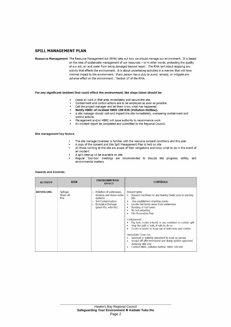
Hawke’s Bay Regional Council
Safeguarding Your Environment Kaitiaki Tuku Iho Page 2

Hawke’s Bay Regional Council
Safeguarding Your Environment Kaitiaki Tuku Iho Page 3

Hawke’s Bay Regional Council
Safeguarding Your Environment Kaitiaki Tuku Iho Page 4

GHD
134 Queen Street East Hastings 4156 T: 64 6 870 9105
© GHD 2014
This document is and shall remain the property of GHD. The document may only be used for the purpose for which it was commissioned and in accordance with the Terms of Engagement for the commission. Unauthorised use of this document in any form whatsoever is prohibited. N:\NZ\Palmerston North\Projects\51\31468\WP\GHD AEE Inputs\Updates May 2014\B1 - Project Description Final 28-05-14.docx
Document Status
Rev No.
Author Reviewer Approved for Issue Name Signature Name Signature Date
0 T Dakers/M Thorne
Tony Harrison Tony Harrison 30/09/13
1 M Thorne Tony Harrison Tony Harrison 23/10/13
2 M Thorne Tony Harrison Tony Harrison 6/12/13
3 M Thorne Tony Harrison Tony Harrison 28/05/14

www.ghd.com